Embed Size (px)
Citation preview

DiaphragmAccumulators
2
Index Page1. Description 3
Introduction 3
Construction 3
2. Applications 43. Technical Data 6
Operation 6
Technical Specifications 6
Temperature Effect 6
Formulas for Sizing Accumulators 7
Sizing Example 7
4. Installation Requirements 85. Model Code 96. Welded Type (non-repairable) Specifications 107. Threaded Type (repairable) Specifications 11
HYDACDiaphragmAccumulators

3
1. DESCRIPTION
INTRODUCTION
HYDAC diaphragm accumulatorsutilize the compressibility of a gas(nitrogen) in storing hydraulic energy.The gas is required because fluidsare practically incompressible andthus, can not store energy bythemselves. The diaphragm isutilized to separate the gas and thefluid sides of the accumulator
The diaphragm accumulatorfunctions by drawing in fluid fromthe hydraulic circuit when thepressure increases and thus,compresses the gas. It returns thisenergy to the circuit as the pressuredecreases by the expansion of thegas.
A poppet is incorporated into thediaphragm to prevent its extrusionthrough the fluid port.
HYDAC manufactures two types ofdiaphragm accumulators:
• welded (non-repairable)
• threaded (repairable)
These have been successfullyapplied to both industrial andmobile applications in energystorage, maintaining pressure,leakage compensation, and vehiclehydraulic systems (e.g. brake andsuspension).
CONSTRUCTION
Welded Type
It consists of:
• an electronic beam welded shellwith gas charging valve oralternately, completely sealed.Fluid ports are available invarious thread configurations.
• a flexible diaphragm to separatethe gas and fluid sides.
• a poppet.
Threaded Type
It consists of:
• a forged upper section with thegas valve.
• a forged lower section with thefluid port.
• a locking ring to fasten the upperand lower sections together.
• a replaceable, flexible diaphragmto separate the gas and fluid sides.
• a poppet
Diaphragm Materials
Not all fluids are compatible withevery elastomer at all temperatures.Therefore, HYDAC offers thefollowing choice of elastomers:
• NBR (Standard Nitrile)
• LT-NBR (Low Temperature Nitrile)
• ECO (Epichlorohydrin)
• IIR (Butyl)
• FPM (Fluorelastomer)
• others available upon request.
Corrosion Protection
HYDAC offers internal and/orexternal protective coatings. If this isinsufficient, stainless steel is alsoavailable.
Mounting Position
Diaphragm accumulators by designmay be mounted in any position. Insystems where contamination is aproblem, we recommend a verticalmount with fluid port orienteddownward.
System Mounting
HYDAC diaphragm accumulatorsare designed to be screwed directlyonto the system. We alsorecommend the use of our mountingcomponents, refer to MountingComponents brochure # A 3.502, tominimize risk of failure due to systemvibrations.
gas valve
accumulatorshell
locking ring
diaphragm
poppet
fluid port
gas valve
accumulatorshell
diaphragm
poppet
fluid port

4
2. APPLICATIONSHYDAC diaphragm accumulatorshave been applied successfully inthe following industries:
• Agriculture
• Forestry
• Machine Tools
• Mining
• Mobile Equipment
• Off Road Equipment
Some examples are shown hereand on the next page.
HYDAC welcomes the opportunityto work with you on yourapplication.
A diaphragm accumulator is used tosupport peak demand and foremergency supply in the event of apump failure
Diaphragm accumulators canenhance motion control anddampen vibration.
With hydraulic suspensions,diaphragm accumulators are usedto absorb shock.

5
These pictures show a heavy dutyshock application.
This picture shows two energystorage applications on fatiguetesting equipment.
6
3. TECHNICAL DATA
OPERATION
Describing the operation ofdiaphragm accumulators:
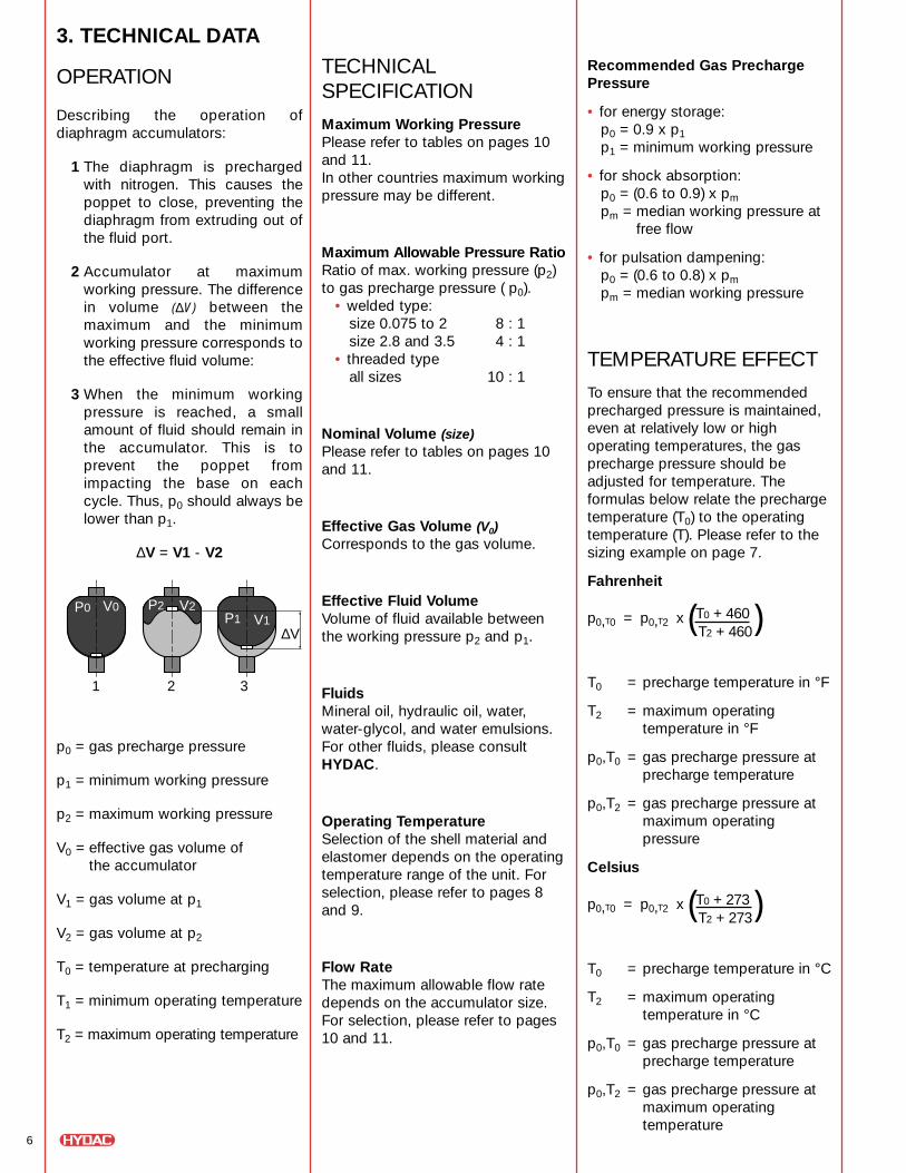
1 The diaphragm is prechargedwith nitrogen. This causes thepoppet to close, preventing thediaphragm from extruding out ofthe fluid port.
2 Accumulator at maximumworking pressure. The differencein volume (∆V) between themaximum and the minimumworking pressure corresponds tothe effective fluid volume:
3 When the minimum workingpressure is reached, a smallamount of fluid should remain inthe accumulator. This is toprevent the poppet fromimpacting the base on eachcycle. Thus, p0 should always belower than p1.
∆V = V1 - V2
p0 = gas precharge pressure
p1 = minimum working pressure
p2 = maximum working pressure
V0 = effective gas volume of the accumulator
V1 = gas volume at p1
V2 = gas volume at p2
T0 = temperature at precharging
T1 = minimum operating temperature
T2 = maximum operating temperature
P0 V0P1 V1
P2 V2
1 32
∆V
Recommended Gas PrechargePressure
• for energy storage:p0 = 0.9 x p1p1 = minimum working pressure
• for shock absorption:p0 = (0.6 to 0.9) x pmpm = median working pressure at
free flow
• for pulsation dampening:p0 = (0.6 to 0.8) x pmpm = median working pressure
TEMPERATURE EFFECT
To ensure that the recommendedprecharged pressure is maintained,even at relatively low or highoperating temperatures, the gasprecharge pressure should beadjusted for temperature. Theformulas below relate the prechargetemperature (T0) to the operatingtemperature (T). Please refer to thesizing example on page 7.
Fahrenheit
p0,T0 = p0,T2 x (T0 + 460 )T2 + 460
T0 = precharge temperature in °F
T2 = maximum operatingtemperature in °F
p0,T0 = gas precharge pressure atprecharge temperature
p0,T2 = gas precharge pressure atmaximum operatingpressure
Celsius
p0,T0 = p0,T2 x (T0 + 273 )T2 + 273
T0 = precharge temperature in °C
T2 = maximum operatingtemperature in °C
p0,T0 = gas precharge pressure atprecharge temperature
p0,T2 = gas precharge pressure atmaximum operatingtemperature
TECHNICALSPECIFICATION
Maximum Working PressurePlease refer to tables on pages 10and 11.In other countries maximum workingpressure may be different.
Maximum Allowable Pressure RatioRatio of max. working pressure (p2)to gas precharge pressure ( p0).
• welded type:size 0.075 to 2 8 : 1size 2.8 and 3.5 4 : 1
• threaded typeall sizes 10 : 1
Nominal Volume (size)Please refer to tables on pages 10and 11.
Effective Gas Volume (V0)Corresponds to the gas volume.
Effective Fluid VolumeVolume of fluid available betweenthe working pressure p2 and p1.
FluidsMineral oil, hydraulic oil, water,water-glycol, and water emulsions.For other fluids, please consultHYDAC.
Operating TemperatureSelection of the shell material andelastomer depends on the operatingtemperature range of the unit. Forselection, please refer to pages 8and 9.
Flow RateThe maximum allowable flow ratedepends on the accumulator size.For selection, please refer to pages10 and 11.

7
FORMULAS FOR SIZINGACCUMULATORSThe compression and expansionprocesses taking place inhydropneumatic accumulator aregoverned by the general gas laws.
The following applies for ideal gases:
p0 x V0n = p1 x V1
n = p2 x V2n,
where the time related change ofstate is represented by the polytropicexponent “n”. For slow expansionand compression processes whichoccur almost isothermically, thepolytropic exponent can be set atn=1. For rapid processes, thediabetic change of state can becalculated using n = k = 1.4 (fornitrogen as a diatomic gas)(1.
For pressures above 3000 psi the realgas behavior deviates considerablyfrom the ideal one, which reduces theeffective fluid volume ∆V. In suchcases a correction is made whichtakes into account a change in theadiabatic exponent (k).
By using the following formulas, therequired gas volume V0 can becalculated for various calculations.
Pressures of up to 150 psi mustalways be used as absolutepressures in the formulas.
Calculation Formulas
polytropic:
isothermal:
(n=1)
adiabatic:
(n = k = 1.4)
Correction factors to take intoaccount the real gas behavior(2
V0,real = Ci x V0,ideal or
∆Vreal = ∆ VidealCi
for adiabatic change of condition:
V0,real = Ca x V0,ideal or
∆Vreal = ∆ VidealCa
1 An estimate of the accumulator size and a selection ofprecharge pressure can be calculated similar to thesample shown. For more accurate sizing and designassistance, please contact HYDAC.
2 The correction factors can be taken from the graphs inthe next column, depending on the pressure ratio p2/p1and the maximum working pressure p2, which is givenas a parameter, for an isothermal or adiabatic
change of condition.
SIZING EXAMPLEA brake cylinder has to be rapidlyoperated by means of anaccumulator. The system mustoperate between 3000 psi and 1500psi. The required fluid volume tooperate properly is 15 in3. Themaximum operating temperature is140°F while the minimum is 50°F.
Given:
max. working pressurep2 = 3000 psi
min. working pressurep1 = 1500 psi
effective fluid volume∆V = 15 in3
max. operating temperatureT2 = 140°F
min. operating temperatureT1 = 50°F
Required:
1 necessary accumulator size,taking into account the real gasbehavior
2 gas precharge pressure p0 at 68°F(T0)
Solution:
Since it is a rapid process, thechange of condition of the gas canbe assumed to be adiabatic.
1 Determination of gas prechargepressure
p0,T2 = 0.9 x p1
= 0.9 x 1500 = 1350 psi.
In order to maintain the minimumworking pressure (p1), one mustcalculate the precharge pressure at T1. p0,T1 = p0,T2 x
= 1350 x
= 1148 psi ≈ 1150 psi
Determination of the required gas volume:
V0, ideal =
1150 =
= 46.5 in3
Taking into account the real gas
behavior:V0,real = Ca x V0, ideal
= 53.9 in3
Selected:Diaphragm accumulatorSBO 200-1 (60 in3)
b) Determination of the gas
precharge pressure
p0 at 68°F:
p0,T0 = p0,T2 x
= 1350 x
= 1188 psi
Selected: Gas precharge pressurep0,T0 ≈ 1200 psi
max
working
pressure p2 = 400 bar (5800 psi)300 bar (4350 psi)200 bar (2900 psi)
max
working
pressure p2 = 400 bar (5800 psi)
300 bar (4350 psi)200 bar (2900 psi)
1
1.7
1.0
1.6
1.5
1.4
1.3
1.2
1.1
2 3 4 5
Correction factor for isothermal change of condition
pressure ratio p2/p1
corr
ectio
n fa
ctor
Ci
Correction factor for adiabatic change of condition
pressure ratio p2/p1
corr
ectio
n fa
ctor
Ca
1
1.7
1.0
1.6
1.5
1.4
1.3
1.2
1.1
2 3 4 5
V0 =∆V
P0
P1
P0
P2
1/n 1/n( () )V0 =
∆V
P0
P1
P0
P2( ) ( )V0 =
∆V
P0
P1
P0
P2
0.714 0.714( () )
T1 + 460
T2 + 460
50 + 460140 + 460
( )( )
∆V
P0, (T1)
P1
P0, (T1)
P2
0.714 0.714( () )15
11501500
11503000
0.714 0.714( () )
T0 + 460T2 + 460( )68 + 460
140 + 460( )
p0 = 2 - Ca ≈ 1.16p1

8
4. INSTALLATIONREQUIREMENTSGeneral SuggestionsWARNING!Hydraulic accumulators arepressurized vessels and onlyqualified technicians should performrecommended repairs. Always drainthe fluid completely from theaccumulator before performing anywork, such as recommended repairs(see Maintenance Instructions) orconnecting pressure gauges. Neverweld, braze, or perform any type of mechanical work on theaccumulator shell.
Precharge new or repairedaccumulators with dry nitrogen to theproper gas precharge pressure (P0).
For more complete details, pleaserefer to HYDAC’s Operating andInstallation Instructions.
Country of InstallationPressure vessel codes varydepending upon the country ofinstallation. In the United States and Canada pressure vessels aregoverned by ASME pressure vesselcode. HYDAC manufactures accordingto these standards.
For installation in countries outsideof the United States, please consult HYDAC for the appropriatecertifications*. The country ofinstallation codes shown below arerequired for ordering: please refer topage 9.
Argentina SAustralia FAustria DBrazil KCanada S/S1Chile SChina A9Finland LFrance BGermany AGreat Britain (UK) KItaly MJapan PMexico ERussia A6Sweden RUSA S
Elastomer Compatibility TableIn order to maximize system performance it is important to match yoursystem fluid and its temperature range with the appropriate elastomercompound. The table below illustrates the most common ones. For specialrequirements, please consult HYDAC.
Operating SomeCompound Temperature Typical
Range Fluids
NBR (BUNA N) 5°F to 180°F mineral oils32°F to 180°F water and water-glycols
LT-NBR (low temp. NBR) -40°F to 180°F mineral oils
ECO (HYDRIN) -20°F to 250°F mineral oils
IIR (BUTYL) -20°F to 200°F phosphate estersbrake fluids
FPM (VITON) 5°F to 300°F chlorinatedhydrocarbons
Notes:1 The operating temperature range does vary with fluid types, please consult
HYDAC for more specific fluid data.
2 The above typical fluids are some examples of the most common fluids, pleaseconsult HYDAC for specific data.
3 For other applications not listed, please consult HYDAC.
!!CAUTION
Gas Charging
Pressurized Vessel –Use Dry Nitrogen Gas Only!
* The European Community (EC) has the Pressure EquipmentDirective (PED) that is being phased in. Contact HYDAC for details.

9
SBO 200 1 E 4 / 112 S – 210 CK 010
Series (see table)
Size (see table)
Configuration/Gas Port
E1 = welded construction, rechargeable, HYDAC gas valve version 1 (M28 x 1.5)E2 = welded construction, factory precharged and sealed, non rechargeable(1
E4 = welded construction, rechargeable, HYDAC gas valve version 4 (8VI-ISO 4570)A6 = threaded construction, rechargeable, HYDAC gas valve version 1 (M28 x 1.5)
Material Code
Depending on application112 = standard for oil service (mineral oil)
Fluid Port1 = carbon steel3 = stainless steel (316)4 = chemically plated carbon steel (water service)(2
6 = low temperature carbon steel (< -20°F)
Shell0 = synthetic coated carbon steel (water service)1 = carbon steel2 = chemically plated carbon steel (water service)(2
4 = stainless steel (316)6 = low temperature carbon steel (< -20°F)
Diaphragm Compound2 = NBR (Buna N)3 = ECO (Hydrin)4 = IIR (Butyl)5 = LT-BNR (low temperature Buna)6 = FPM (Viton)7 = others
Country of Installation
S = USAOthers on request (refer to page 8)
Maximum Working Pressure in bar
(see table, for E2 design this may vary depending upon the gas precharge pressure)
Connection Thread
A = BSP (ISO 228)B = Metric (DIN 13)C = SAE (ANSI B 1.1)D = NPT (ANSI B 1.2)K = Hexagonal(3
CK= Standard SAE connection
Gas Precharge Pressure (p0) in bar(4
Not All Combinations Available
Notes:1) Up to size 12) Only wetted surfaces3) For units with internal threads only4) Only required for E2-model
5. Model Code: Diaphragm Accumulators

10
6. WELDED TYPE (non-repairable)
1) Stainless steel version for chemical, water, and oil service2) Diameter at electron beam weld may be up to +0.150” larger3) May be supplied with adapter
Series Max. Size Effective MAWP Wt. A øD(2 Thread F K (hex) Qp2:p0 (liters) Gas Vol in3 psi/bar lbs/kg in/mm in/mm SAE NPTF(3 in/mm gpm
SBO 250 8 : 1 0.075 5 3600 1.5 2.68 2.52 9/16-189 UNF 3/8” 1.18 10250 0.7 68 64 30
SBO 210 8 : 1 0.16 10 2600/180(1 1.8 3.15 2.91 9/16-189 UNF 3/8” 1.18 103000/210 0.8 80 74 30
SBO 210 8 : 1 0.32 20 2400/160(1 2.9 3.66 3.66 3/4-16 UNF 1/2” 1.18 253000/210 1.3 93 93 30
SBO 210 8 : 1 0.5 30 3000 3.7 4.35 4.13 3/4-16 UNF 1/2” 1.18 25210 1.7 124 105 30
SBO 330 8 : 1 0.6 36 4700 7.3 5.04 4.53 3/4-16 UNF 1/2” 1.61 25330 3.3 128 115 41
SBO 210 8 : 1 0.75 45 2000/140(1 6.2 4.88 4.76 3/4-16 UNF 1/2” 1.61 253000/210 2.8 124 121 41
SBO 330 8 : 1 0.75 45 4700 8.9 4.78 4.96 3/4-16 UNF 1/2” 1.61 25330 4.0 122 126 41
SBO 200 8 : 1 1 60 3000 7.9 5.39 5.35 3/4-16 UNF 1/2” 1.61 25210 3.6 137 136 41
SBO 140 8 : 1 1.4 85 2000 8.6 5.91 5.71 3/4-16 UNF 1/2” 1.61 25140 3.9 150 145 41
SBO 210 8 : 1 1.4 85 3000 11.9 6.14 5.91 3/4-16 UNF 1/2” 1.61 25210 5.4 156 150 41
SBO 330 8 : 1 1.4 85 4700 16.6 6.33 6.1 3/4-16 UNF 1/2” 1.61 25330 7.5 160 155 41
SBO 100 8 : 1 2 120 1500/100(1 8.8 6.57 6.30 1 1/16-12 UNF 3/4” 1.81 401500/100 4.0 167 160 46
SBO 210 8 : 1 2 120 3000 14.6 6.81 6.57 1 1/16-12 UNF 3/4” 1.81 40210 6.6 173 167 46
SBO 330 8 : 1 2 120 4700 17.7 7.12 6.77 1 1/16-12 UNF 3/4” 1.81 40330 8.0 180 172 46
SBO 210 4 : 1 2.8 170 3000 18.0 8.94 6.57 1 1/16-12 UNF 3/4” 1.81 40210 8.2 227 167 46
SBO 250 4 : 1 3.5 230 3000 24.6 11.14 6.69 1 1/16-12 UNF 3/4” 1.81 40210 11.2 283 170 46
SBO 330 4 : 1 3.5 230 4700 30.6 10.78 6.77 1 1/16-12 UNF 3/4” 1.81 40330 13.8 274 172 46

Max. Size Effective MAWP Wt. A B øD Thread F K (hex) øL M NQ
Series p2:p0 (liters) Gas Vol psi lbs in in in SAE in in in ingpm
in3 bar kg mm mm mm mm mm mm mm
SBO 500 10 : 1 0.1 6 7200 4.2 4.33 1.18 3.74 3/4-16 1.26 2.68 0.87 1.38 25500 1.9 110 30 95 68 68 22 35
SBO 500 10 : 1 0.25 15 5000/350(1 8.6 5.04 0.79 4.53 3/4-16 1.42 3.62 0.71 2.17 257200/500 3.9 128 20 115 36 92 18 55
SBO 750 10 : 1 0.25 15 8700/600(1 19.8 5.35 0.43 6.02 3/4-16 1.42 4.49 0.59 2.48 2510000/750 9.0 136 11 153 36 114 15 63
SBO 450 10 : 1 0.6 36 3600/250(1 12.6 6.69 0.75 5.51 3/4-16 1.61 4.53 1.77 2.24 254700/330 5.7 170 19 140 41 115 45 57
SBO 210 10 : 1 1.3 80 3000 18.7 7.48 0.31 6.69 3/4-16 1.26 5.71 2.24 2.17 25210 8.5 190 8 170 32 145 57 55
SBO 400 10 : 1 1.3 80 5800 24.7 7.75 1.10 7.91 3/4-16 1.97 6.30 1.97 2.56 25400 11.2 197 28 201 50 160 50 65
SBO 250 10 : 1 2 120 2600/180(1 25.1 8.93 0.67 7.91 1 1/16-12 1.61 6.61 2.44 2.52 403600/250 11.4 227 17 201 41 168 62 64
11
7. THREADED TYPE (repairable)
1) Stainless steel version for chemical, water, and oil service

©C
opyr
ight
200
0 H
YD
AC
TE
CH
NO
LO
GY
CO
RP
OR
AT
ION
- B
roch
ure
- D
iaph
ragm
Acc
umul
ator
s#0
2071
831
/ 06
.00
HYDAC CORPORATION2280 City Line Road • Bethlehem, PA 18017Phone (610) 264-9503 • Fax (610) 264-7529www.hydacusa.com • [email protected]
Bladder AccumulatorsThe bladder style accumulator is a great general purpose accumulator. It has a widerange of sizes for energy storage requirements and is well suited for shockapplications.
Nominal volume 1 qt. to 15 gal.
Max. working pressure 3000, 5000 and up to 15000 psi
Flow rate up to 480 gpm
Other Products from HYDAC’s Accumulator Line
Piston AccumulatorsA wide range of piston accumulators is available. Piston position monitoring isavailable using proximity switches, extending piston rod or ultrasonictechniques. Auxiliary gas bottles are frequently used with piston accumulatorsto provide the required gas volume.
Nominal volume 1 qt. to 100 gal.
Max. working pressure 3000, 5000, and up to 15000 psi
Flow Rate up to 2000 gpm
Mounting ComponentsHYDAC mounting components are used to mount all types of hydro-pneumatic accumulators safely and simply, regardless of the mountingposition. Our wide range includes suitable mounting components for everytype of hydro pneumatic accumulator. Mounting components are usedprimarily for the following: to fix the accumulator into position, to carry theweight of the accumulator, and to counteract the forces exerted by thehydraulic lines. HYDAC also offers base brackets for larger accumulators forproper support and isolation from system vibrations. The brackets incorporatea rubber support ring for this reason. All mounting components can be easilybolted to your system.
Charging & GaugingTo maintain system performance, HYDAC recommends a regular check of thegas precharge pressure. A loss in the gas precharge pressure will cause adrop in the system efficiency and could cause damage to the bladder,diaphragm or piston accumulator. By means of a charging and gauging unit,hydro-pneumatics accumulators are precharged with dry nitrogen or theirexisting gas precharge pressure is checked. For these purposes, a chargingand gauging unit is connected to a commercially available nitrogen bottle viaa flexible hose. The charging and gauging units incorporate a gauge, checkvalve in the charging connection, manual bleed valve and T-handle.
Request catalog # 02071832
Request catalog # 02068597
Request catalog # 02071834
Request catalog # 02071833