Embed Size (px)
Citation preview
DIAGONALLY REINFORCED
CONCRETE COUPLING BEAMS: EFFECTS OF AXIAL RESTRAINT
By
Ashwin Poudel
Rémy D. Lequesne
Andrés Lepage
Structural Engineering and Engineering Materials SL Report 18-3
September 2018
THE UNIVERSITY OF KANSAS CENTER FOR RESEARCH, INC. 2385 Irving Hill Road, Lawrence, Kansas 66045-7563

DIAGONALLY REINFORCED CONCRETE COUPLING BEAMS: EFFECTS OF AXIAL RESTRAINT
By
Ashwin Poudel
Rémy D. Lequesne
Andrés Lepage
Structural Engineering and Engineering Materials SL Report 18-3
THE UNIVERSITY OF KANSAS CENTER FOR RESEARCH, INC. LAWRENCE, KANSAS
September 2018

i
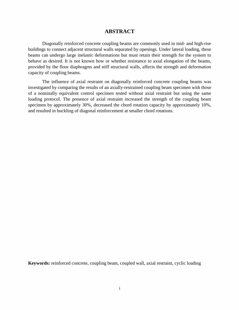
ABSTRACT
Diagonally reinforced concrete coupling beams are commonly used in mid- and high-rise buildings to connect adjacent structural walls separated by openings. Under lateral loading, these beams can undergo large inelastic deformations but must retain their strength for the system to behave as desired. It is not known how or whether resistance to axial elongation of the beams, provided by the floor diaphragms and stiff structural walls, affects the strength and deformation capacity of coupling beams.
The influence of axial restraint on diagonally reinforced concrete coupling beams was investigated by comparing the results of an axially-restrained coupling beam specimen with those of a nominally equivalent control specimen tested without axial restraint but using the same loading protocol. The presence of axial restraint increased the strength of the coupling beam specimen by approximately 30%, decreased the chord rotation capacity by approximately 10%, and resulted in buckling of diagonal reinforcement at smaller chord rotations.
Keywords: reinforced concrete, coupling beam, coupled wall, axial restraint, cyclic loading
ii
ACKNOWLEDGMENTS
This report was prepared as an M.S. project by Ashwin Poudel under the direction of Prof. Rémy Lequesne.
Ashwin would like to acknowledge his fellow graduate students, Shahedreen Ameen and Alexander Weber-Kamin, for providing help and technical support when he needed it. He is grateful for the help and support provided by laboratory technicians David Woody and Kent Dye during specimen construction, casting, and testing. Finally, Ashwin would like to thank the student research assistants who spent numerous hours in the laboratory helping to construct and test the specimen.
iii
TABLE OF CONTENTS CHAPTER 1: INTRODUCTION ........................................................................................................................ 1
1.1 Background ................................................................................................................................... 1 1.2 Brief summary of methodology .................................................................................................... 2
CHAPTER 2: LITERATURE REVIEW ................................................................................................................ 4 2.1 Review of previous research ......................................................................................................... 5 2.2 Summary ..................................................................................................................................... 12 2.3 Design of diagonally reinforced coupling beams ........................................................................ 13
2.3.1 ACI Building Code provisions .............................................................................................. 13 CHAPTER 3: EXPERIMENTAL PROGRAM .................................................................................................... 16
3.1 Specimen design and construction ............................................................................................. 16 3.1.1 Materials ............................................................................................................................. 17 3.1.2 Construction ........................................................................................................................ 18
3.2 Test setup .................................................................................................................................... 18 3.3 Instrumentation .......................................................................................................................... 20 3.4 Loading protocol ......................................................................................................................... 22
CHAPTER 4: RESULTS AND OBSERVATIONS ............................................................................................... 23 4.1 Shear versus chord rotation ........................................................................................................ 23
4.1.1 Chord rotation ..................................................................................................................... 23 4.1.2 Specimen response and observations ................................................................................ 24
4.2 Chord rotation capacity and axial restraint ................................................................................ 26 4.3 Progression of damage ............................................................................................................... 28 4.4 Beam elongation and axial force ................................................................................................ 30
4.4.1 Beam elongation ................................................................................................................. 30 4.4.2 Axial force ........................................................................................................................... 31
4.5 Beam strength ............................................................................................................................. 34 4.6 Summary of results ..................................................................................................................... 35
CHAPTER 5: SUMMARY AND CONCLUSIONS ............................................................................................. 36 5.1 Summary ..................................................................................................................................... 36 5.2 Conclusions ................................................................................................................................. 36 5.3 Future work ................................................................................................................................. 37
REFERENCES ................................................................................................................................................ 38
1
CHAPTER 1: INTRODUCTION
1.1 BACKGROUND
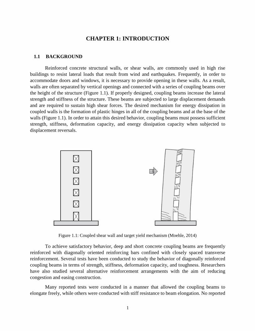
Reinforced concrete structural walls, or shear walls, are commonly used in high rise buildings to resist lateral loads that result from wind and earthquakes. Frequently, in order to accommodate doors and windows, it is necessary to provide opening in these walls. As a result, walls are often separated by vertical openings and connected with a series of coupling beams over the height of the structure (Figure 1.1). If properly designed, coupling beams increase the lateral strength and stiffness of the structure. These beams are subjected to large displacement demands and are required to sustain high shear forces. The desired mechanism for energy dissipation in coupled walls is the formation of plastic hinges in all of the coupling beams and at the base of the walls (Figure 1.1). In order to attain this desired behavior, coupling beams must possess sufficient strength, stiffness, deformation capacity, and energy dissipation capacity when subjected to displacement reversals.
Figure 1.1: Coupled shear wall and target yield mechanism (Moehle, 2014)
To achieve satisfactory behavior, deep and short concrete coupling beams are frequently reinforced with diagonally oriented reinforcing bars confined with closely spaced transverse reinforcement. Several tests have been conducted to study the behavior of diagonally reinforced coupling beams in terms of strength, stiffness, deformation capacity, and toughness. Researchers have also studied several alternative reinforcement arrangements with the aim of reducing congestion and easing construction.
Many reported tests were conducted in a manner that allowed the coupling beams to elongate freely, while others were conducted with stiff resistance to beam elongation. No reported
2
studies have directly examined the effect of axial restraint, and the resulting axial forces, on beam behavior. It is likely that stiff walls and diaphragms resist the elongation of coupling beams that occurs as damage accumulates under displacement reversals. This restraining effect might influence deformation capacity, as well as increase flexural capacity and shear demand. Axial forces might also make the diagonal reinforcement more susceptible to buckling. The main objective of this study is to quantify the effect of axial restraint on coupling beam behavior in terms of strength and deformation capacity.
1.2 BRIEF SUMMARY OF METHODOLOGY
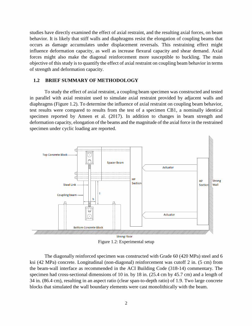
To study the effect of axial restraint, a coupling beam specimen was constructed and tested in parallel with axial restraint used to simulate axial restraint provided by adjacent walls and diaphragms (Figure 1.2). To determine the influence of axial restraint on coupling beam behavior, test results were compared to results from the test of a specimen CB1, a nominally identical specimen reported by Ameen et al. (2017). In addition to changes in beam strength and deformation capacity, elongation of the beams and the magnitude of the axial force in the restrained specimen under cyclic loading are reported.
Figure 1.2: Experimental setup
The diagonally reinforced specimen was constructed with Grade 60 (420 MPa) steel and 6 ksi (42 MPa) concrete. Longitudinal (non-diagonal) reinforcement was cutoff 2 in. (5 cm) from the beam-wall interface as recommended in the ACI Building Code (318-14) commentary. The specimen had cross-sectional dimensions of 10 in. by 18 in. (25.4 cm by 45.7 cm) and a length of 34 in. (86.4 cm), resulting in an aspect ratio (clear span-to-depth ratio) of 1.9. Two large concrete blocks that simulated the wall boundary elements were cast monolithically with the beam.
3
The specimen was tested with one concrete block bolted to the laboratory strong floor and other block linked to a pair of hydraulic actuators. The actuator was connected to the strong wall and the top concrete block through a series of HP and HSS steel fixtures. The vertical HP section nearest the specimen transmitted compression through two HSS sections and tension through six high-strength threaded rods. The specimen was subjected to reversed cyclic displacements with the ratio between the displacements applied by the two actuators maintained such that an inflection point occurred near mid-span of the beam throughout the test. Out-of-plane displacement was prevented by braces attached to the HP section (not shown in Figure 1.2). Axial restraint was provided with two steel links attached to the top and bottom block and both sides of the specimen as shown in Figure 1.2.
4
CHAPTER 2: LITERATURE REVIEW
This literature review was adapted from Ameen (2019).
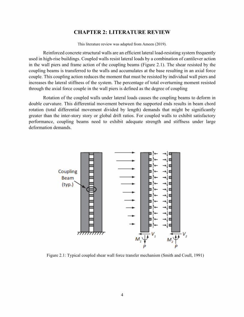
Reinforced concrete structural walls are an efficient lateral load-resisting system frequently used in high-rise buildings. Coupled walls resist lateral loads by a combination of cantilever action in the wall piers and frame action of the coupling beams (Figure 2.1). The shear resisted by the coupling beams is transferred to the walls and accumulates at the base resulting in an axial force couple. This coupling action reduces the moment that must be resisted by individual wall piers and increases the lateral stiffness of the system. The percentage of total overturning moment resisted through the axial force couple in the wall piers is defined as the degree of coupling
Rotation of the coupled walls under lateral loads causes the coupling beams to deform in double curvature. This differential movement between the supported ends results in beam chord rotation (total differential movement divided by length) demands that might be significantly greater than the inter-story story or global drift ratios. For coupled walls to exhibit satisfactory performance, coupling beams need to exhibit adequate strength and stiffness under large deformation demands.
Figure 2.1: Typical coupled shear wall force transfer mechanism (Smith and Coull, 1991)
5
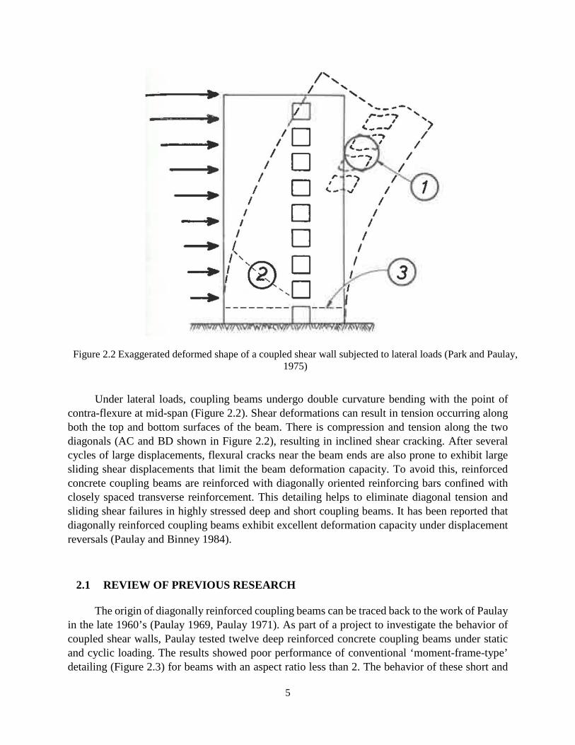
Figure 2.2 Exaggerated deformed shape of a coupled shear wall subjected to lateral loads (Park and Paulay, 1975)
Under lateral loads, coupling beams undergo double curvature bending with the point of contra-flexure at mid-span (Figure 2.2). Shear deformations can result in tension occurring along both the top and bottom surfaces of the beam. There is compression and tension along the two diagonals (AC and BD shown in Figure 2.2), resulting in inclined shear cracking. After several cycles of large displacements, flexural cracks near the beam ends are also prone to exhibit large sliding shear displacements that limit the beam deformation capacity. To avoid this, reinforced concrete coupling beams are reinforced with diagonally oriented reinforcing bars confined with closely spaced transverse reinforcement. This detailing helps to eliminate diagonal tension and sliding shear failures in highly stressed deep and short coupling beams. It has been reported that diagonally reinforced coupling beams exhibit excellent deformation capacity under displacement reversals (Paulay and Binney 1984).
2.1 REVIEW OF PREVIOUS RESEARCH
The origin of diagonally reinforced coupling beams can be traced back to the work of Paulay in the late 1960’s (Paulay 1969, Paulay 1971). As part of a project to investigate the behavior of coupled shear walls, Paulay tested twelve deep reinforced concrete coupling beams under static and cyclic loading. The results showed poor performance of conventional ‘moment-frame-type’ detailing (Figure 2.3) for beams with an aspect ratio less than 2. The behavior of these short and

6
relatively deep beams was dominated by shear, and as a result they exhibited diagonal tension or sliding shear failures at relatively low deformation demands. The deformation capacities of these beams were inadequate to satisfy the demands in coupled wall structures under large earthquakes. Furthermore, instead of the longitudinal reinforcement strain profile expected based on imposed moments (tension in half the span and compression in the other), tensile strains were observed over the entire beam span for both top and bottom steel. This indicated that traditional reinforced concrete flexural design principles could not be applied to deep and short coupling beams subjected to large shear stresses. These specimens were free to elongate during testing.
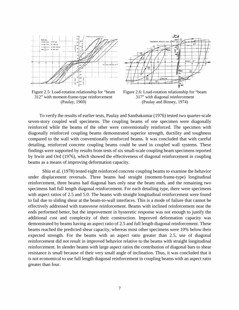
Based on these findings, Paulay and Binney proposed an alternative detailing approach to improve coupling beam performance. Three short and deep coupling beams with aspect ratios less than 2 were tested. The specimens had the main reinforcement placed in the form of two intersecting diagonals (Figure 2.4). Providing diagonal reinforcement in coupling beams significantly improved their deformation capacity and toughness, as seen in the plots of shear force versus chord rotation for beam 312 (Figure 2.5) and beam 317 (Figure 2.6).
Figure 2.3 : Conventionally reinforced coupling beam
Figure 2.4: Diagonally reinforced coupling beam
7
Figure 2.5: Load-rotation relationship for “beam
312” with moment-frame-type reinforcement (Paulay, 1969)
Figure 2.6: Load-rotation relationship for “beam 317” with diagonal reinforcement
(Paulay and Binney, 1974)
To verify the results of earlier tests, Paulay and Santhakumar (1976) tested two quarter-scale seven-story coupled wall specimens. The coupling beams of one specimen were diagonally reinforced while the beams of the other were conventionally reinforced. The specimen with diagonally reinforced coupling beams demonstrated superior strength, ductility and toughness compared to the wall with conventionally reinforced beams. It was concluded that with careful detailing, reinforced concrete coupling beams could be used in coupled wall systems. These findings were supported by results from tests of six small-scale coupling beam specimens reported by Irwin and Ord (1976), which showed the effectiveness of diagonal reinforcement in coupling beams as a means of improving deformation capacity.
Shiu et al. (1978) tested eight reinforced concrete coupling beams to examine the behavior under displacement reversals. Three beams had straight (moment-frame-type) longitudinal reinforcement, three beams had diagonal bars only near the beam ends, and the remaining two specimens had full length diagonal reinforcement. For each detailing type, there were specimens with aspect ratios of 2.5 and 5.0. The beams with straight longitudinal reinforcement were found to fail due to sliding shear at the beam-to-wall interfaces. This is a mode of failure that cannot be effectively addressed with transverse reinforcement. Beams with inclined reinforcement near the ends performed better, but the improvement in hysteretic response was not enough to justify the additional cost and complexity of their construction. Improved deformation capacity was demonstrated by beams having an aspect ratio of 2.5 and full length diagonal reinforcement. These beams reached the predicted shear capacity, whereas most other specimens were 10% below their expected strength. For the beams with an aspect ratio greater than 2.5, use of diagonal reinforcement did not result in improved behavior relative to the beams with straight longitudinal reinforcement. In slender beams with large aspect ratios the contribution of diagonal bars to shear resistance is small because of their very small angle of inclination. Thus, it was concluded that it is not economical to use full length diagonal reinforcement in coupling beams with an aspect ratio greater than four.
8
Diagonally reinforced coupling beams require a large amount of confinement to avoid diagonal bar buckling. In addition, the diagonal reinforcement must intersect the wall boundary, which is typically a well-confined boundary element. The resulting reinforcement congestion causes diagonally reinforced beams to be difficult and time consuming to construct in practice. So, even though it was demonstrated by various tests that the use of diagonal reinforcement results in excellent behavior of coupling beams, researchers have continued to experiment with alternative detailing arrangements.
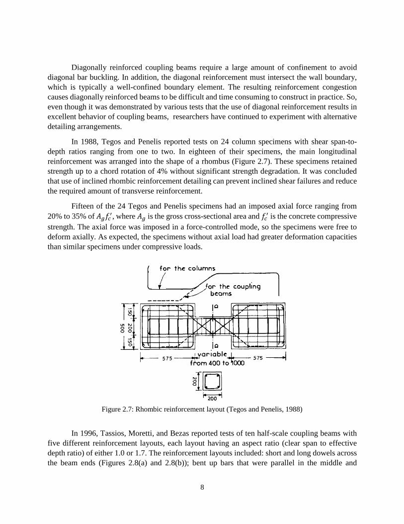
In 1988, Tegos and Penelis reported tests on 24 column specimens with shear span-to-depth ratios ranging from one to two. In eighteen of their specimens, the main longitudinal reinforcement was arranged into the shape of a rhombus (Figure 2.7). These specimens retained strength up to a chord rotation of 4% without significant strength degradation. It was concluded that use of inclined rhombic reinforcement detailing can prevent inclined shear failures and reduce the required amount of transverse reinforcement.
Fifteen of the 24 Tegos and Penelis specimens had an imposed axial force ranging from 20% to 35% of 𝐴𝐴𝑔𝑔𝑓𝑓𝑐𝑐′, where 𝐴𝐴𝑔𝑔 is the gross cross-sectional area and 𝑓𝑓𝑐𝑐′ is the concrete compressive strength. The axial force was imposed in a force-controlled mode, so the specimens were free to deform axially. As expected, the specimens without axial load had greater deformation capacities than similar specimens under compressive loads.
Figure 2.7: Rhombic reinforcement layout (Tegos and Penelis, 1988)
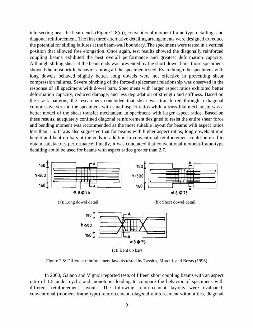
In 1996, Tassios, Moretti, and Bezas reported tests of ten half-scale coupling beams with five different reinforcement layouts, each layout having an aspect ratio (clear span to effective depth ratio) of either 1.0 or 1.7. The reinforcement layouts included: short and long dowels across the beam ends (Figures 2.8(a) and 2.8(b)); bent up bars that were parallel in the middle and
9
intersecting near the beam ends (Figure 2.8(c)); conventional moment-frame-type detailing; and diagonal reinforcement. The first three alternative detailing arrangements were designed to reduce the potential for sliding failures at the beam-wall boundary. The specimens were tested in a vertical position that allowed free elongation. Once again, test results showed the diagonally reinforced coupling beams exhibited the best overall performance and greatest deformation capacity. Although sliding shear at the beam ends was prevented by the short dowel bars, those specimens showed the most brittle behavior among all the specimen tested. Even though the specimens with long dowels behaved slightly better, long dowels were not effective in preventing shear compression failures. Severe pinching of the force-displacement relationship was observed in the response of all specimens with dowel bars. Specimens with larger aspect ratios exhibited better deformation capacity, reduced damage, and less degradation of strength and stiffness. Based on the crack patterns, the researchers concluded that shear was transferred through a diagonal compressive strut in the specimens with small aspect ratios while a truss-like mechanism was a better model of the shear transfer mechanism in specimens with larger aspect ratios. Based on these results, adequately confined diagonal reinforcement designed to resist the entire shear force and bending moment was recommended as the most suitable layout for beams with aspect ratios less than 1.5. It was also suggested that for beams with higher aspect ratios, long dowels at mid height and bent-up bars at the ends in addition to conventional reinforcement could be used to obtain satisfactory performance. Finally, it was concluded that conventional moment-frame-type detailing could be used for beams with aspect ratios greater than 2.7.
(a): Long dowel detail (b): Short dowel detail
(c): Bent up bars
Figure 2.8: Different reinforcement layouts tested by Tassios, Moretti, and Bezas (1996)
In 2000, Galano and Vignoli reported tests of fifteen short coupling beams with an aspect ratio of 1.5 under cyclic and monotonic loading to compare the behavior of specimens with different reinforcement layouts. The following reinforcement layouts were evaluated: conventional (moment-frame-type) reinforcement, diagonal reinforcement without ties, diagonal
10
reinforcement with ties, and bars inclined to form a rhombic configuration. The behavior of these specimens was compared in terms of failure mechanism, peak strength, stiffness degradation, and deformation capacity. Results indicated that the rhombic layout resulted in the highest rotational ductility values, improved strength retention and similar toughness with respect to the specimens with well confined diagonal reinforcement. However, the rhombic layout resulted in 17% less strength than specimens with a diagonal layout and the same geometrical percentage of steel area.
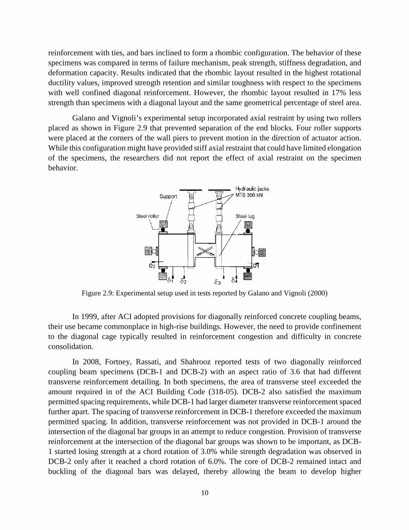
Galano and Vignoli’s experimental setup incorporated axial restraint by using two rollers placed as shown in Figure 2.9 that prevented separation of the end blocks. Four roller supports were placed at the corners of the wall piers to prevent motion in the direction of actuator action. While this configuration might have provided stiff axial restraint that could have limited elongation of the specimens, the researchers did not report the effect of axial restraint on the specimen behavior.
Figure 2.9: Experimental setup used in tests reported by Galano and Vignoli (2000)
In 1999, after ACI adopted provisions for diagonally reinforced concrete coupling beams, their use became commonplace in high-rise buildings. However, the need to provide confinement to the diagonal cage typically resulted in reinforcement congestion and difficulty in concrete consolidation.
In 2008, Fortney, Rassati, and Shahrooz reported tests of two diagonally reinforced coupling beam specimens (DCB-1 and DCB-2) with an aspect ratio of 3.6 that had different transverse reinforcement detailing. In both specimens, the area of transverse steel exceeded the amount required in of the ACI Building Code (318-05). DCB-2 also satisfied the maximum permitted spacing requirements, while DCB-1 had larger diameter transverse reinforcement spaced further apart. The spacing of transverse reinforcement in DCB-1 therefore exceeded the maximum permitted spacing. In addition, transverse reinforcement was not provided in DCB-1 around the intersection of the diagonal bar groups in an attempt to reduce congestion. Provision of transverse reinforcement at the intersection of the diagonal bar groups was shown to be important, as DCB-1 started losing strength at a chord rotation of 3.0% while strength degradation was observed in DCB-2 only after it reached a chord rotation of 6.0%. The core of DCB-2 remained intact and buckling of the diagonal bars was delayed, thereby allowing the beam to develop higher

11
deformation capacity and shear strength. The final recommendation was to increase the minimum transverse reinforcement ratio required by ACI 318-05.
To reduce reinforcement congestion, an alternative confinement reinforcement detail was permitted in ACI 318-08. In this detailing arrangement, hoops are used to confine the entire coupling beam cross section (full section confinement, Figure 2.10) instead of using hoops around the inclined diagonal reinforcement (diagonal confinement, Figure 2.11). Naish, Klemencic, and Wallace (2009) tested eight half-scale specimens to compare the behavior of specimens with full-section confinement to that of specimens with diagonal confinement detailing. Five specimens had an aspect ratio of 2.4, representing beams in typical residential buildings, and three specimens had an aspect ratio of 3.3, representing beams in typical office buildings. Two specimens with each aspect ratio were constructed with the diagonal confinement layout while the other specimens were constructed with full section confinement reinforcement. Test results indicated that the use of full section confinement reinforcement results in behavior that is similar to that of specimens with diagonal confinement reinforcement.
Among the eight specimens, four were constructed with reinforced concrete (RC) and post-tensioned (PT) slabs to determine the effect of the slabs on load deformation response. The presence of the RC slab increased beam shear strength by 17%. This higher strength was primarily attributed to the increase in nominal flexural strength of the slender beam caused by the presence of the slab. Beams with and without the RC slabs all elongated approximately 1 in. (2.54 cm) over the course of the test, showing that the slab did not provide significant restraint to elongation in these tests. The specimen with a PT slab exhibited higher shear strength due to the axial force applied to the specimen by the tensioned strands. The axial force also led to more pronounced strength degradation at chord rotations of 8 and 10%. Elongations of these specimens were 30 to 40% less than for the RC slab specimens. It was concluded that presence of a slab only had a modest influence on strength, stiffness, deformation capacity, and observed damage.
Figure 2.10: Confinement detailing for diagonal bar groups
Figure 2.11:Confinement detailing for full section confinement
12
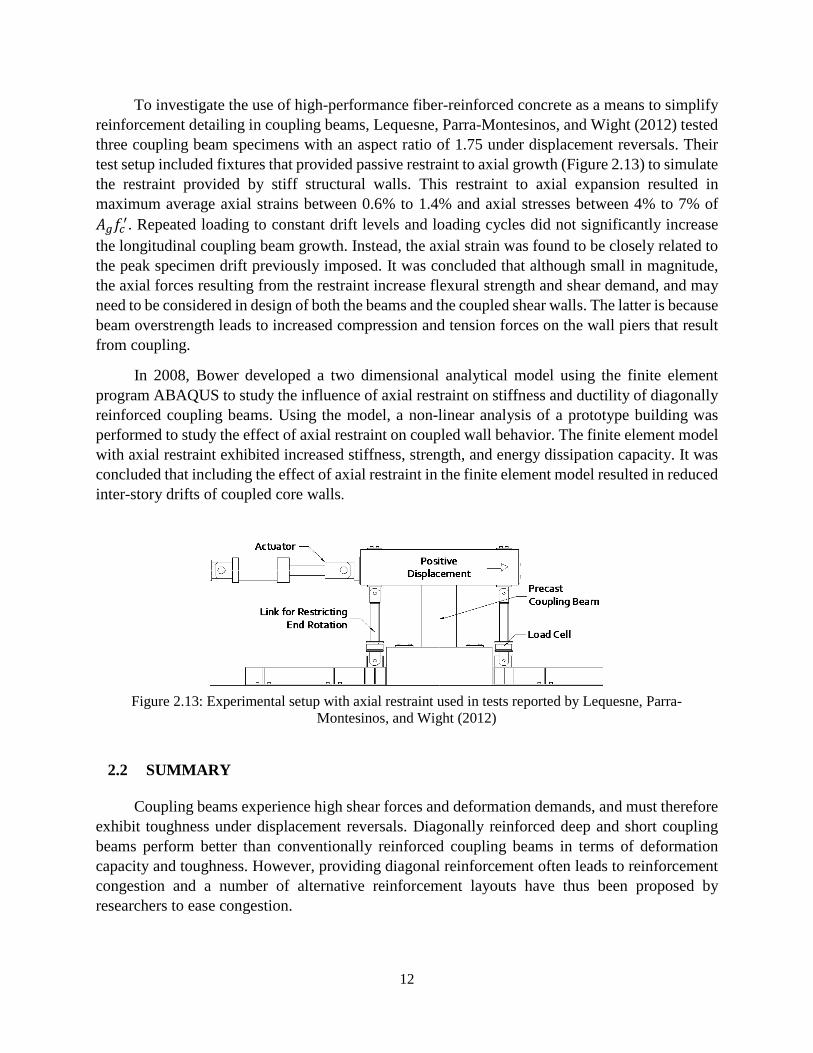
To investigate the use of high-performance fiber-reinforced concrete as a means to simplify reinforcement detailing in coupling beams, Lequesne, Parra-Montesinos, and Wight (2012) tested three coupling beam specimens with an aspect ratio of 1.75 under displacement reversals. Their test setup included fixtures that provided passive restraint to axial growth (Figure 2.13) to simulate the restraint provided by stiff structural walls. This restraint to axial expansion resulted in maximum average axial strains between 0.6% to 1.4% and axial stresses between 4% to 7% of 𝐴𝐴𝑔𝑔𝑓𝑓𝑐𝑐′. Repeated loading to constant drift levels and loading cycles did not significantly increase the longitudinal coupling beam growth. Instead, the axial strain was found to be closely related to the peak specimen drift previously imposed. It was concluded that although small in magnitude, the axial forces resulting from the restraint increase flexural strength and shear demand, and may need to be considered in design of both the beams and the coupled shear walls. The latter is because beam overstrength leads to increased compression and tension forces on the wall piers that result from coupling.
In 2008, Bower developed a two dimensional analytical model using the finite element program ABAQUS to study the influence of axial restraint on stiffness and ductility of diagonally reinforced coupling beams. Using the model, a non-linear analysis of a prototype building was performed to study the effect of axial restraint on coupled wall behavior. The finite element model with axial restraint exhibited increased stiffness, strength, and energy dissipation capacity. It was concluded that including the effect of axial restraint in the finite element model resulted in reduced inter-story drifts of coupled core walls.
Figure 2.13: Experimental setup with axial restraint used in tests reported by Lequesne, Parra-
Montesinos, and Wight (2012)
2.2 SUMMARY
Coupling beams experience high shear forces and deformation demands, and must therefore exhibit toughness under displacement reversals. Diagonally reinforced deep and short coupling beams perform better than conventionally reinforced coupling beams in terms of deformation capacity and toughness. However, providing diagonal reinforcement often leads to reinforcement congestion and a number of alternative reinforcement layouts have thus been proposed by researchers to ease congestion.
13
While tests of coupling beams have been conducted with and without axial restraint, no tests were found that directly evaluated the effects of axial restraint provided by stiff structural walls and diaphragms on the deformation capacity and strength of diagonally reinforced coupling beams. Based on the tests conducted by Lequesne, Parra-Montesinos, and Wight, axial forces that occur in response to axial restraint might affect flexural strength and shear demand. If correct, these effects may need to be considered when designing both the beams and coupled shear walls. An analytical study by Bower indicated that the presence of axial restraint results in increased stiffness and energy dissipation capacity of coupling beams.
ACI 318-14 is silent on the effects of axial restraint in the design of coupling beams and wall piers in coupled core walls. Assuming negligible axial restraint from floor slabs and wall piers might result in the underestimation of beam flexural strength and therefore also both beam shear demands and wall axial force demands. Moreover, the axial restraint might result in the early buckling of diagonal bars, thereby adversely influencing the deformation capacity and mode of failure of coupling beams.
There is a need to study the effect of axial restraint in more detail and quantify the influence of axial restraint on coupling beam behavior.
2.3 DESIGN OF DIAGONALLY REINFORCED COUPLING BEAMS
Coupled walls provide excellent earthquake-resistant performance in high-rise structures because of their ability to provide large lateral stiffness and deformation capacity (Saatcioglu, Derecho, and Corley 1987). The favorable plastic mechanism in coupled walls includes yielding of all the coupling beams followed by yielding at the base of the individual walls. As a result, coupled wall systems possess substantial toughness.
The behavior of coupled walls is often described in terms of the degree of coupling, which is defined as the percentage of total overturning moment resisted through the axial force couple in the wall piers. Coupling beams must possess adequate strength, stiffness and ductility to achieve the required degree of coupling. To improve the performance of coupling beams in regions of moderate to high seismic hazard, diagonal reinforcement is typically provided. These diagonally reinforced coupling beams have been shown to exhibit excellent toughness and deformation capacity (Paulay 1971).
2.3.1 ACI BUILDING CODE PROVISIONS
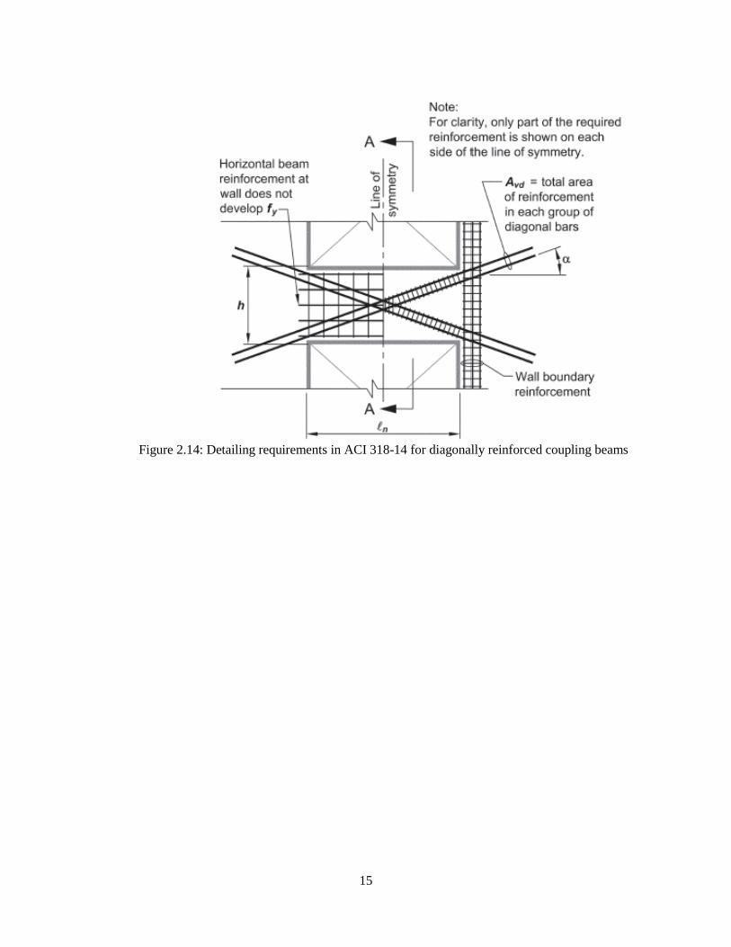
A diagonally reinforced coupling beam consists of two intersecting groups of diagonal bars placed symmetrically about the mid-span of the beam. Diagonal reinforcement is effective only if the bars are placed with a large angle of inclination relative to the horizontal. Thus, for beams with aspect ratios (clear span to height) greater than 4, only special moment frame detailing is permitted (ACI 318-14). Diagonal reinforcement is required for coupling beams with aspect ratios less than
14
2 and nominal shear stresses greater than or equal to 4�𝑓𝑓𝑐𝑐′ [psi] (0.33�𝑓𝑓𝑐𝑐′MPa). For coupling beams with aspect ratios of 2 to 4, the ACI Building Code permits either a diagonal or moment frame-type reinforcement layout.
When diagonal reinforcement is used, the diagonal bar group must be placed in two or more layers and arranged symmetrically about midspan. The diagonal bar groups must be designed to resist the entire shear and moment demands. The nominal shear strength of a diagonally reinforced coupling beam is calculated using Eq. 2-1.
𝑉𝑉𝑛𝑛 = 2𝐴𝐴𝑣𝑣𝑣𝑣 𝑓𝑓𝑦𝑦𝑠𝑠𝑠𝑠𝑠𝑠(𝛼𝛼) ≤ 10 �𝑓𝑓𝑐𝑐′𝑏𝑏ℎ
Eq. 2-1
Where: 𝐴𝐴𝑣𝑣𝑣𝑣 is the total reinforcement area of each diagonal bar group, 𝑓𝑓𝑦𝑦 is the yield stress of the diagonal reinforcement (limited to 60 ksi, [420 MPa]), 𝑓𝑓𝑐𝑐′ is the compressive strength of concrete, 𝑏𝑏 and ℎ are the width and overall depth of the beam, respectively, and 𝛼𝛼 is the inclination of the diagonal group (Figure 2.14). The ACI Building Code limits the maximum nominal strength to 10 �𝑓𝑓𝑐𝑐′ [psi] (0.83 �𝑓𝑓𝑐𝑐′ [MPa]), although it has been argued that nominal shear strengths greater than 6 �𝑓𝑓𝑐𝑐′ [psi] (0.5 �𝑓𝑓𝑐𝑐′ [MPa]) are difficult to achieve due to reinforcement congestion (Harries et al. 2005).
ACI 318-14 requires transverse confinement reinforcement in coupling beams to delay diagonal bar buckling and maintain the integrity of the concrete core after concrete spalling. Two transverse reinforcement layouts are permitted: a) closely spaced hoops enclosing each diagonal bar group independently (diagonal confinement), or b) closely spaced hoops that enclose the beam cross-section (full section confinement). In both cases, the area and spacing of hoops must satisfy the requirements for confinement of special moment frame columns.
Each diagonal bar is required to be embedded into the wall at least 25 percent more than the calculated development length. However, the (horizontal) longitudinal beam reinforcement does not need to be developed and the commentary of ACI 318-14 recommends that it be terminated close to the beam wall interface (Figure 2.14). Recent tests reported by Lim et al. (2016) have shown that this provision often leads to a concentration of damage at the beam ends. Conversely, embedding the horizontal beam reinforcement into the wall a length sufficient to develop 1.25 times the yield stress of the bar at the face of the wall was shown by Lim et al. to improve the energy dissipation capacity by distributing the damage over the span of the coupling beam.
15
Figure 2.14: Detailing requirements in ACI 318-14 for diagonally reinforced coupling beams
16
CHAPTER 3: EXPERIMENTAL PROGRAM
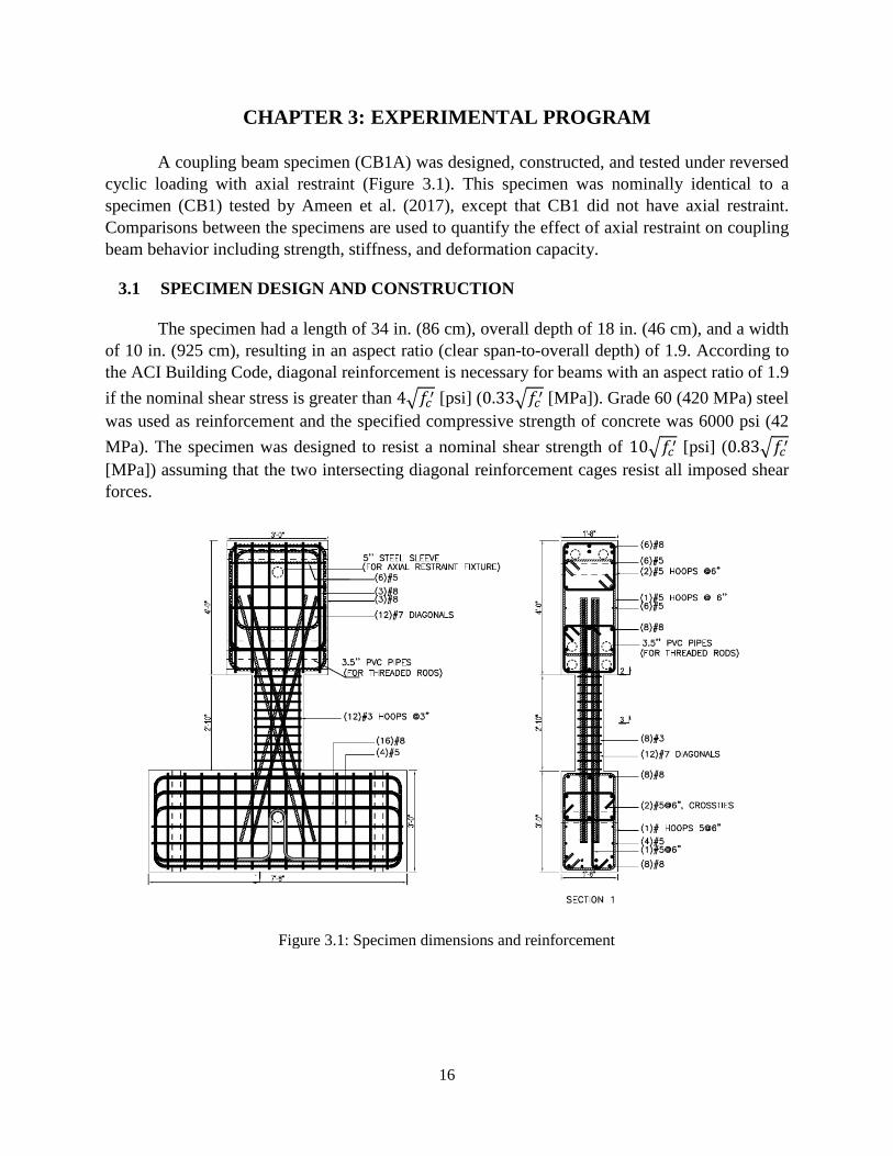
A coupling beam specimen (CB1A) was designed, constructed, and tested under reversed cyclic loading with axial restraint (Figure 3.1). This specimen was nominally identical to a specimen (CB1) tested by Ameen et al. (2017), except that CB1 did not have axial restraint. Comparisons between the specimens are used to quantify the effect of axial restraint on coupling beam behavior including strength, stiffness, and deformation capacity.
3.1 SPECIMEN DESIGN AND CONSTRUCTION
The specimen had a length of 34 in. (86 cm), overall depth of 18 in. (46 cm), and a width of 10 in. (925 cm), resulting in an aspect ratio (clear span-to-overall depth) of 1.9. According to the ACI Building Code, diagonal reinforcement is necessary for beams with an aspect ratio of 1.9 if the nominal shear stress is greater than 4�𝑓𝑓𝑐𝑐′ [psi] (0.33�𝑓𝑓𝑐𝑐′ [MPa]). Grade 60 (420 MPa) steel was used as reinforcement and the specified compressive strength of concrete was 6000 psi (42 MPa). The specimen was designed to resist a nominal shear strength of 10�𝑓𝑓𝑐𝑐′ [psi] (0.83�𝑓𝑓𝑐𝑐′ [MPa]) assuming that the two intersecting diagonal reinforcement cages resist all imposed shear forces.
Figure 3.1: Specimen dimensions and reinforcement
17
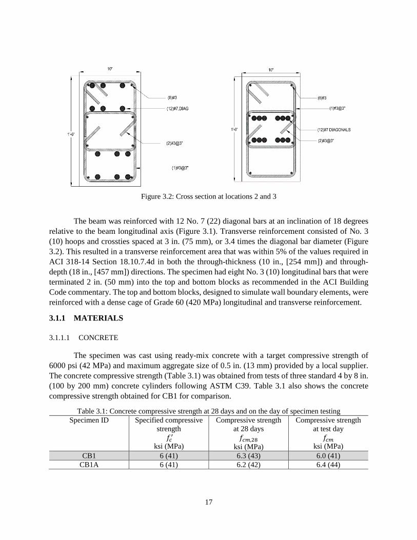
Figure 3.2: Cross section at locations 2 and 3
The beam was reinforced with 12 No. 7 (22) diagonal bars at an inclination of 18 degrees relative to the beam longitudinal axis (Figure 3.1). Transverse reinforcement consisted of No. 3 (10) hoops and crossties spaced at 3 in. (75 mm), or 3.4 times the diagonal bar diameter (Figure 3.2). This resulted in a transverse reinforcement area that was within 5% of the values required in ACI 318-14 Section 18.10.7.4d in both the through-thickness (10 in., [254 mm]) and through-depth (18 in., [457 mm]) directions. The specimen had eight No. 3 (10) longitudinal bars that were terminated 2 in. (50 mm) into the top and bottom blocks as recommended in the ACI Building Code commentary. The top and bottom blocks, designed to simulate wall boundary elements, were reinforced with a dense cage of Grade 60 (420 MPa) longitudinal and transverse reinforcement.
3.1.1 MATERIALS
3.1.1.1 CONCRETE
The specimen was cast using ready-mix concrete with a target compressive strength of 6000 psi (42 MPa) and maximum aggregate size of 0.5 in. (13 mm) provided by a local supplier. The concrete compressive strength (Table 3.1) was obtained from tests of three standard 4 by 8 in. (100 by 200 mm) concrete cylinders following ASTM C39. Table 3.1 also shows the concrete compressive strength obtained for CB1 for comparison.
Table 3.1: Concrete compressive strength at 28 days and on the day of specimen testing Specimen ID Specified compressive
strength 𝑓𝑓𝑐𝑐′
ksi (MPa)
Compressive strength at 28 days 𝑓𝑓𝑐𝑐𝑐𝑐,28
ksi (MPa)
Compressive strength at test day
𝑓𝑓𝑐𝑐𝑐𝑐 ksi (MPa)
CB1 6 (41) 6.3 (43) 6.0 (41) CB1A 6 (41) 6.2 (42) 6.4 (44)
18
3.1.1.2 REINFORCING STEEL
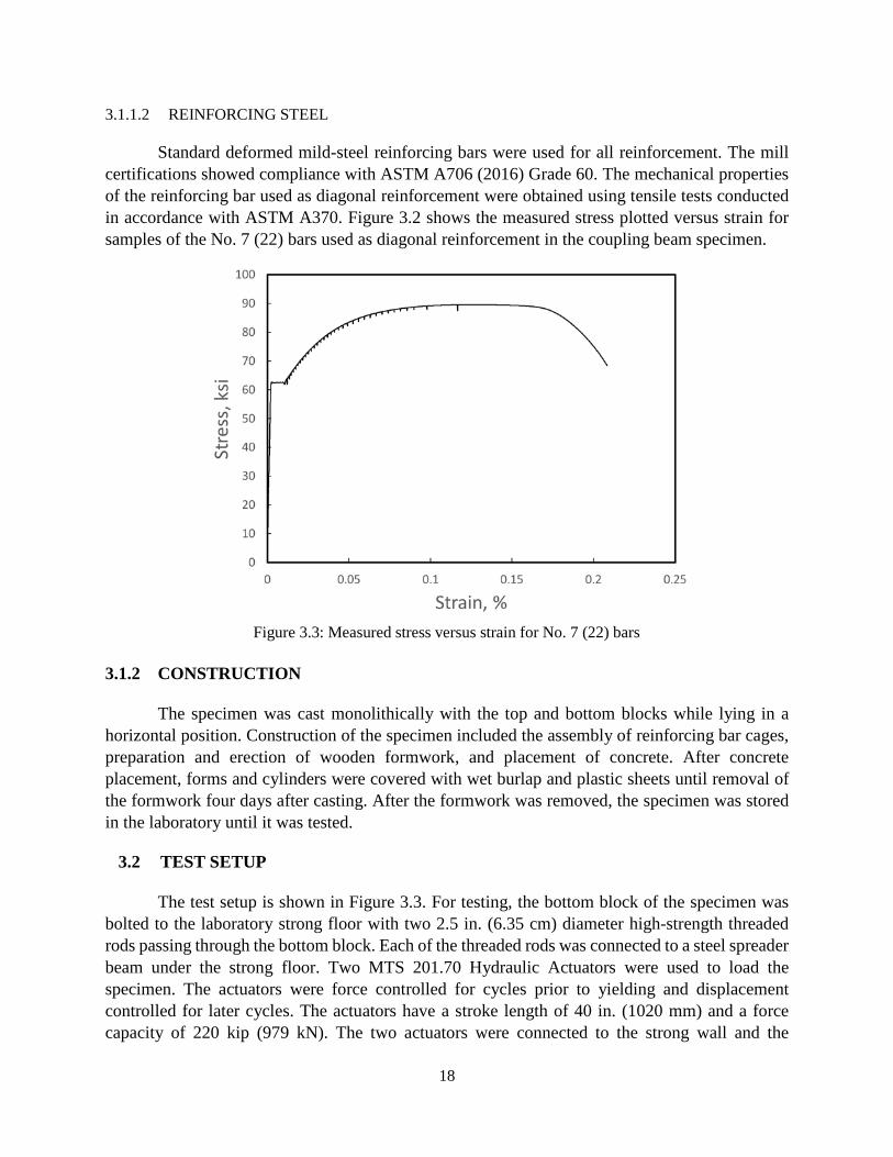
Standard deformed mild-steel reinforcing bars were used for all reinforcement. The mill certifications showed compliance with ASTM A706 (2016) Grade 60. The mechanical properties of the reinforcing bar used as diagonal reinforcement were obtained using tensile tests conducted in accordance with ASTM A370. Figure 3.2 shows the measured stress plotted versus strain for samples of the No. 7 (22) bars used as diagonal reinforcement in the coupling beam specimen.
Figure 3.3: Measured stress versus strain for No. 7 (22) bars
3.1.2 CONSTRUCTION
The specimen was cast monolithically with the top and bottom blocks while lying in a horizontal position. Construction of the specimen included the assembly of reinforcing bar cages, preparation and erection of wooden formwork, and placement of concrete. After concrete placement, forms and cylinders were covered with wet burlap and plastic sheets until removal of the formwork four days after casting. After the formwork was removed, the specimen was stored in the laboratory until it was tested.
3.2 TEST SETUP
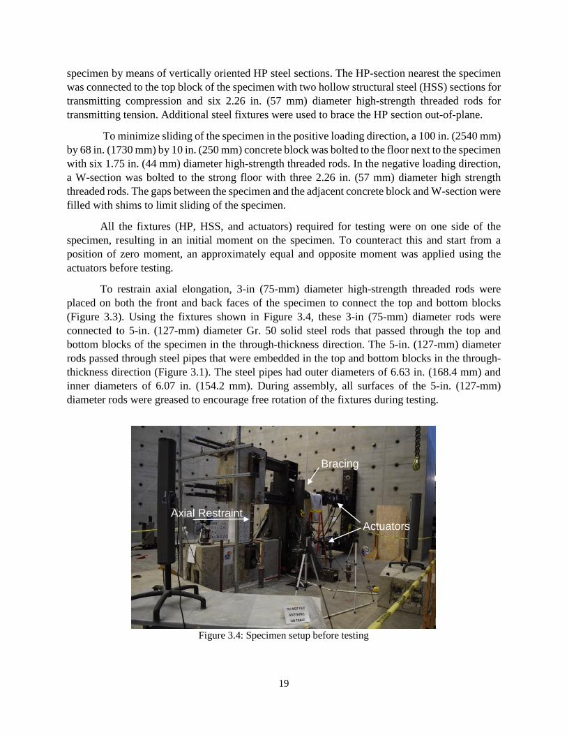
The test setup is shown in Figure 3.3. For testing, the bottom block of the specimen was bolted to the laboratory strong floor with two 2.5 in. (6.35 cm) diameter high-strength threaded rods passing through the bottom block. Each of the threaded rods was connected to a steel spreader beam under the strong floor. Two MTS 201.70 Hydraulic Actuators were used to load the specimen. The actuators were force controlled for cycles prior to yielding and displacement controlled for later cycles. The actuators have a stroke length of 40 in. (1020 mm) and a force capacity of 220 kip (979 kN). The two actuators were connected to the strong wall and the
ksi
19
specimen by means of vertically oriented HP steel sections. The HP-section nearest the specimen was connected to the top block of the specimen with two hollow structural steel (HSS) sections for transmitting compression and six 2.26 in. (57 mm) diameter high-strength threaded rods for transmitting tension. Additional steel fixtures were used to brace the HP section out-of-plane.
To minimize sliding of the specimen in the positive loading direction, a 100 in. (2540 mm) by 68 in. (1730 mm) by 10 in. (250 mm) concrete block was bolted to the floor next to the specimen with six 1.75 in. (44 mm) diameter high-strength threaded rods. In the negative loading direction, a W-section was bolted to the strong floor with three 2.26 in. (57 mm) diameter high strength threaded rods. The gaps between the specimen and the adjacent concrete block and W-section were filled with shims to limit sliding of the specimen.
All the fixtures (HP, HSS, and actuators) required for testing were on one side of the specimen, resulting in an initial moment on the specimen. To counteract this and start from a position of zero moment, an approximately equal and opposite moment was applied using the actuators before testing.
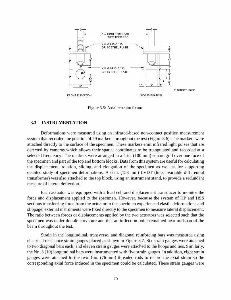
To restrain axial elongation, 3-in (75-mm) diameter high-strength threaded rods were placed on both the front and back faces of the specimen to connect the top and bottom blocks (Figure 3.3). Using the fixtures shown in Figure 3.4, these 3-in (75-mm) diameter rods were connected to 5-in. (127-mm) diameter Gr. 50 solid steel rods that passed through the top and bottom blocks of the specimen in the through-thickness direction. The 5-in. (127-mm) diameter rods passed through steel pipes that were embedded in the top and bottom blocks in the through-thickness direction (Figure 3.1). The steel pipes had outer diameters of 6.63 in. (168.4 mm) and inner diameters of 6.07 in. (154.2 mm). During assembly, all surfaces of the 5-in. (127-mm) diameter rods were greased to encourage free rotation of the fixtures during testing.
Figure 3.4: Specimen setup before testing
Actuators
Bracing
Axial Restraint
20
Figure 3.5: Axial restraint fixture
3.3 INSTRUMENTATION
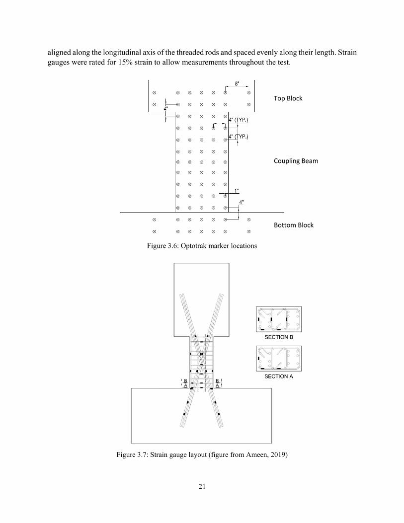
Deformations were measured using an infrared-based non-contact position measurement system that recorded the position of 59 markers throughout the test (Figure 3.6). The markers were attached directly to the surface of the specimen. These markers emit infrared light pulses that are detected by cameras which allows their spatial coordinates to be triangulated and recorded at a selected frequency. The markers were arranged in a 4 in. (100 mm) square grid over one face of the specimen and part of the top and bottom blocks. Data from this system are useful for calculating the displacement, rotation, sliding, and elongation of the specimen as well as for supporting detailed study of specimen deformations. A 6 in. (153 mm) LVDT (linear variable differential transformer) was also attached to the top block, using an instrument stand, to provide a redundant measure of lateral deflection.
Each actuator was equipped with a load cell and displacement transducer to monitor the force and displacement applied to the specimen. However, because the system of HP and HSS sections transferring force from the actuator to the specimen experienced elastic deformations and slippage, external instruments were fixed directly to the specimen to measure lateral displacement. The ratio between forces or displacements applied by the two actuators was selected such that the specimen was under double curvature and that an inflection point remained near midspan of the beam throughout the test.
Strain in the longitudinal, transverse, and diagonal reinforcing bars was measured using electrical resistance strain gauges placed as shown in Figure 3.7. Six strain gauges were attached to two diagonal bars each, and eleven strain gauges were attached to the hoops and ties. Similarly, the No. 3 (10) longitudinal bars were instrumented with five strain gauges. In addition, eight strain gauges were attached to the two 3-in. (76-mm) threaded rods to record the axial strain so the corresponding axial force induced in the specimen could be calculated. These strain gauges were
21
aligned along the longitudinal axis of the threaded rods and spaced evenly along their length. Strain gauges were rated for 15% strain to allow measurements throughout the test.
Figure 3.6: Optotrak marker locations
Figure 3.7: Strain gauge layout (figure from Ameen, 2019)
Top Block
Coupling Beam
Bottom Block
22
3.4 LOADING PROTOCOL
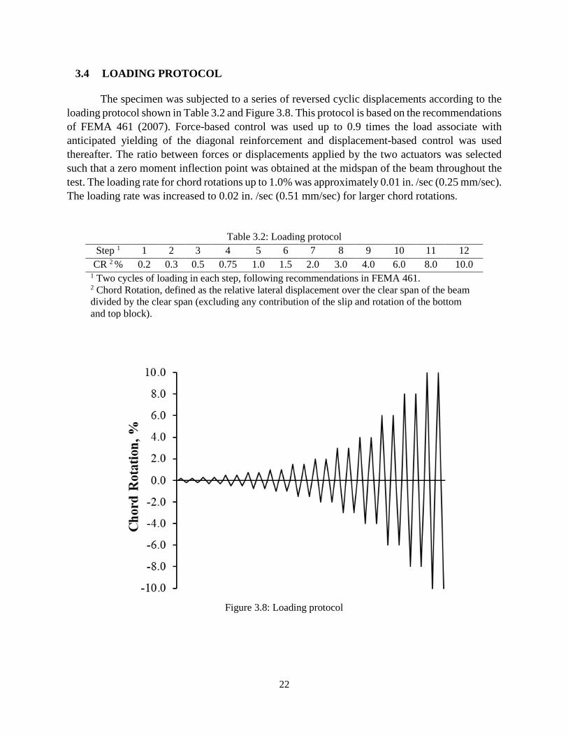
The specimen was subjected to a series of reversed cyclic displacements according to the loading protocol shown in Table 3.2 and Figure 3.8. This protocol is based on the recommendations of FEMA 461 (2007). Force-based control was used up to 0.9 times the load associate with anticipated yielding of the diagonal reinforcement and displacement-based control was used thereafter. The ratio between forces or displacements applied by the two actuators was selected such that a zero moment inflection point was obtained at the midspan of the beam throughout the test. The loading rate for chord rotations up to 1.0% was approximately 0.01 in. /sec (0.25 mm/sec). The loading rate was increased to 0.02 in. /sec (0.51 mm/sec) for larger chord rotations.
Table 3.2: Loading protocol Step 1 1 2 3 4 5 6 7 8 9 10 11 12
CR 2 % 0.2 0.3 0.5 0.75 1.0 1.5 2.0 3.0 4.0 6.0 8.0 10.0 1 Two cycles of loading in each step, following recommendations in FEMA 461. 2 Chord Rotation, defined as the relative lateral displacement over the clear span of the beam divided by the clear span (excluding any contribution of the slip and rotation of the bottom and top block).
Figure 3.8: Loading protocol
23
CHAPTER 4: RESULTS AND OBSERVATIONS
4.1 SHEAR VERSUS CHORD ROTATION
4.1.1 CHORD ROTATION
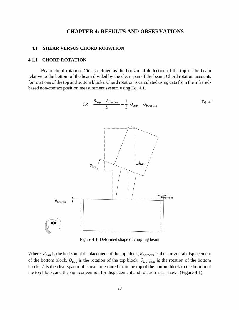
Beam chord rotation, CR, is defined as the horizontal deflection of the top of the beam relative to the bottom of the beam divided by the clear span of the beam. Chord rotation accounts for rotations of the top and bottom blocks. Chord rotation is calculated using data from the infrared-based non-contact position measurement system using Eq. 4.1.
𝐶𝐶𝐶𝐶 =𝛿𝛿𝑡𝑡𝑡𝑡𝑡𝑡 − 𝛿𝛿𝑏𝑏𝑡𝑡𝑡𝑡𝑡𝑡𝑡𝑡𝑐𝑐
𝐿𝐿−
12
(𝛳𝛳𝑡𝑡𝑡𝑡𝑡𝑡 + 𝛳𝛳𝑏𝑏𝑡𝑡𝑡𝑡𝑡𝑡𝑡𝑡𝑐𝑐) Eq. 4.1
Figure 4.1: Deformed shape of coupling beam
Where: 𝛿𝛿𝑡𝑡𝑡𝑡𝑡𝑡 is the horizontal displacement of the top block, 𝛿𝛿𝑏𝑏𝑡𝑡𝑡𝑡𝑡𝑡𝑡𝑡𝑐𝑐 is the horizontal displacement of the bottom block, 𝛳𝛳𝑡𝑡𝑡𝑡𝑡𝑡 is the rotation of the top block, 𝛳𝛳𝑏𝑏𝑡𝑡𝑡𝑡𝑡𝑡𝑡𝑡𝑐𝑐 is the rotation of the bottom block, 𝐿𝐿 is the clear span of the beam measured from the top of the bottom block to the bottom of the top block, and the sign convention for displacement and rotation is as shown (Figure 4.1).
𝜃𝜃𝑡𝑡𝑡𝑡𝑡𝑡
𝜃𝜃𝑏𝑏𝑡𝑡𝑡𝑡𝑡𝑡𝑡𝑡𝑐𝑐
𝛿𝛿𝑡𝑡𝑡𝑡𝑡𝑡
𝛿𝛿𝑏𝑏𝑡𝑡𝑡𝑡𝑡𝑡𝑡𝑡𝑐𝑐
24
4.1.2 SPECIMEN RESPONSE AND OBSERVATIONS
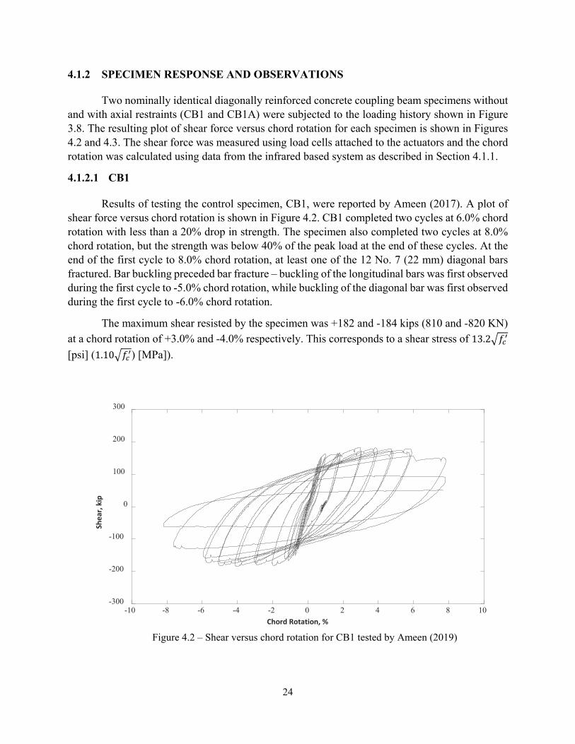
Two nominally identical diagonally reinforced concrete coupling beam specimens without and with axial restraints (CB1 and CB1A) were subjected to the loading history shown in Figure 3.8. The resulting plot of shear force versus chord rotation for each specimen is shown in Figures 4.2 and 4.3. The shear force was measured using load cells attached to the actuators and the chord rotation was calculated using data from the infrared based system as described in Section 4.1.1.
4.1.2.1 CB1
Results of testing the control specimen, CB1, were reported by Ameen (2017). A plot of shear force versus chord rotation is shown in Figure 4.2. CB1 completed two cycles at 6.0% chord rotation with less than a 20% drop in strength. The specimen also completed two cycles at 8.0% chord rotation, but the strength was below 40% of the peak load at the end of these cycles. At the end of the first cycle to 8.0% chord rotation, at least one of the 12 No. 7 (22 mm) diagonal bars fractured. Bar buckling preceded bar fracture – buckling of the longitudinal bars was first observed during the first cycle to -5.0% chord rotation, while buckling of the diagonal bar was first observed during the first cycle to -6.0% chord rotation.
The maximum shear resisted by the specimen was +182 and -184 kips (810 and -820 KN) at a chord rotation of +3.0% and -4.0% respectively. This corresponds to a shear stress of 13.2�𝑓𝑓𝑐𝑐′ [psi] (1.10�𝑓𝑓𝑐𝑐′) [MPa]).
Figure 4.2 – Shear versus chord rotation for CB1 tested by Ameen (2019)
-10 -8 -6 -4 -2 0 2 4 6 8 10Chord Rotation, %
-300
-200
-100
0
100
200
300
Shea
r, ki
p
25
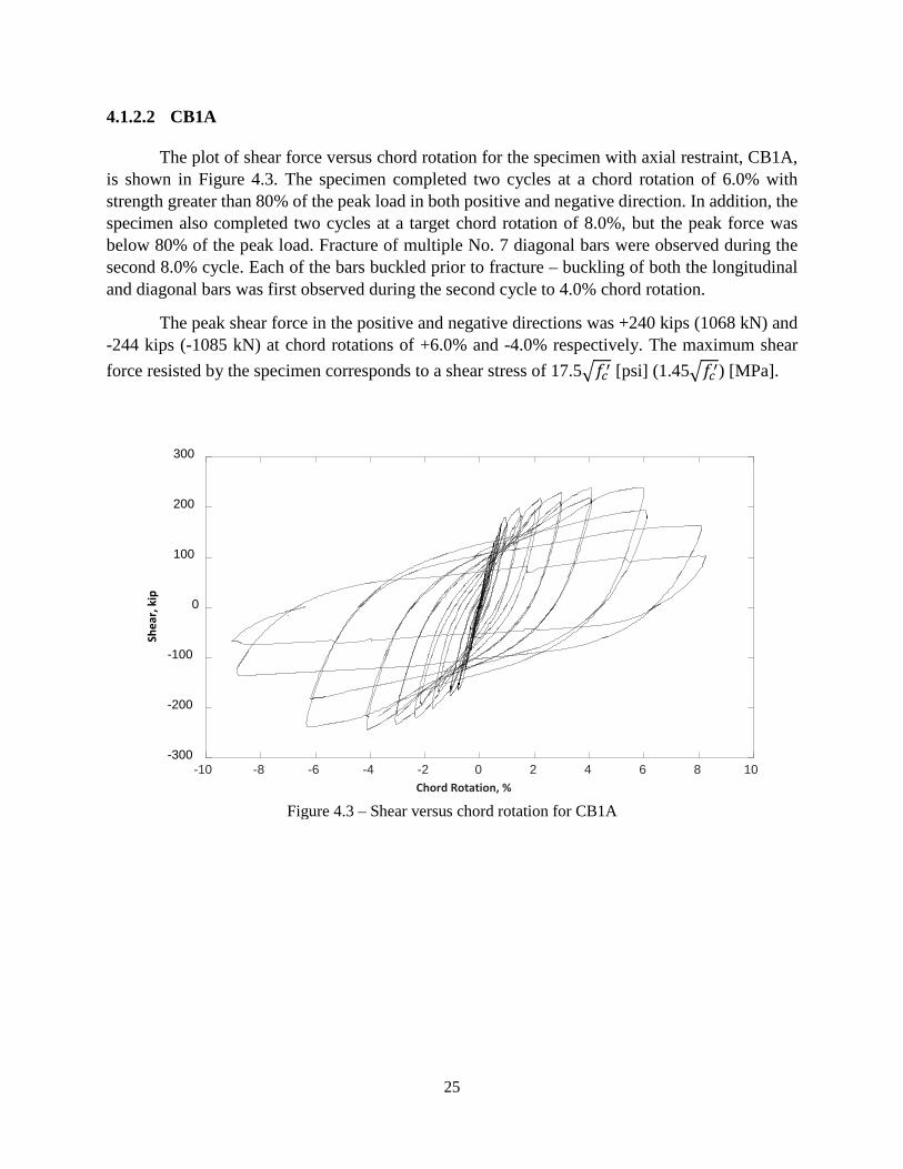
4.1.2.2 CB1A
The plot of shear force versus chord rotation for the specimen with axial restraint, CB1A, is shown in Figure 4.3. The specimen completed two cycles at a chord rotation of 6.0% with strength greater than 80% of the peak load in both positive and negative direction. In addition, the specimen also completed two cycles at a target chord rotation of 8.0%, but the peak force was below 80% of the peak load. Fracture of multiple No. 7 diagonal bars were observed during the second 8.0% cycle. Each of the bars buckled prior to fracture – buckling of both the longitudinal and diagonal bars was first observed during the second cycle to 4.0% chord rotation.
The peak shear force in the positive and negative directions was +240 kips (1068 kN) and -244 kips (-1085 kN) at chord rotations of +6.0% and -4.0% respectively. The maximum shear force resisted by the specimen corresponds to a shear stress of 17.5�𝑓𝑓𝑐𝑐′ [psi] (1.45�𝑓𝑓𝑐𝑐′) [MPa].
Figure 4.3 – Shear versus chord rotation for CB1A
-10 -8 -6 -4 -2 0 2 4 6 8 10Chord Rotation, %
-300
-200
-100
0
100
200
300
Shea
r, ki
p
26
4.2 CHORD ROTATION CAPACITY AND AXIAL RESTRAINT
Deformation capacity was quantified using two common definitions of chord rotation capacity. The calculated values were then compared to determine whether axial restraint correlated with a change in deformation capacity.
Specimen chord rotation capacity was first defined as the average of the maximum chord rotation imposed in each loading direction without more than 20% reduction in strength. Per this definition, CB1 had a chord rotation capacity of 7.1% (8.0% and 6.3% in the positive and negative directions), and CB1A had a chord rotation capacity of 6.2% (6.0% in the positive direction and 6.3% in the negative direction). Thus, axial restraint was correlated with an approximately 13% reduction in chord rotation capacity when this definition was used.
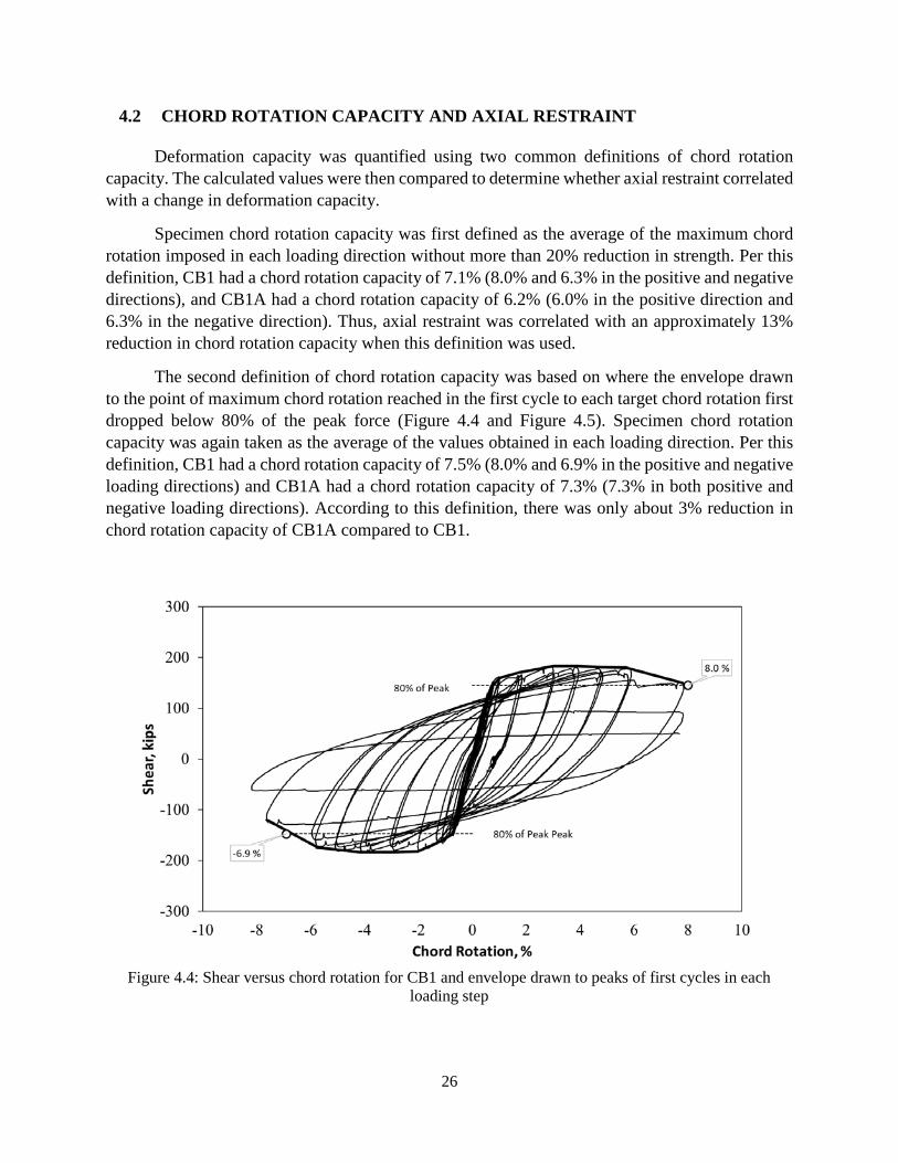
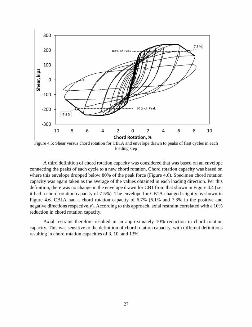
The second definition of chord rotation capacity was based on where the envelope drawn to the point of maximum chord rotation reached in the first cycle to each target chord rotation first dropped below 80% of the peak force (Figure 4.4 and Figure 4.5). Specimen chord rotation capacity was again taken as the average of the values obtained in each loading direction. Per this definition, CB1 had a chord rotation capacity of 7.5% (8.0% and 6.9% in the positive and negative loading directions) and CB1A had a chord rotation capacity of 7.3% (7.3% in both positive and negative loading directions). According to this definition, there was only about 3% reduction in chord rotation capacity of CB1A compared to CB1.
Figure 4.4: Shear versus chord rotation for CB1 and envelope drawn to peaks of first cycles in each
loading step
27
Figure 4.5: Shear versus chord rotation for CB1A and envelope drawn to peaks of first cycles in each
loading step
A third definition of chord rotation capacity was considered that was based on an envelope connecting the peaks of each cycle to a new chord rotation. Chord rotation capacity was based on where this envelope dropped below 80% of the peak force (Figure 4.6). Specimen chord rotation capacity was again taken as the average of the values obtained in each loading direction. Per this definition, there was no change in the envelope drawn for CB1 from that shown in Figure 4.4 (i.e. it had a chord rotation capacity of 7.5%). The envelope for CB1A changed slightly as shown in Figure 4.6. CB1A had a chord rotation capacity of 6.7% (6.1% and 7.3% in the positive and negative directions respectively). According to this approach, axial restraint correlated with a 10% reduction in chord rotation capacity.
Axial restraint therefore resulted in an approximately 10% reduction in chord rotation capacity. This was sensitive to the definition of chord rotation capacity, with different definitions resulting in chord rotation capacities of 3, 10, and 13%.

28
Figure 4.6: Shear versus chord rotation for CB1A and envelope drawn to peaks of each cycle to a new
chord rotation
4.3 PROGRESSION OF DAMAGE
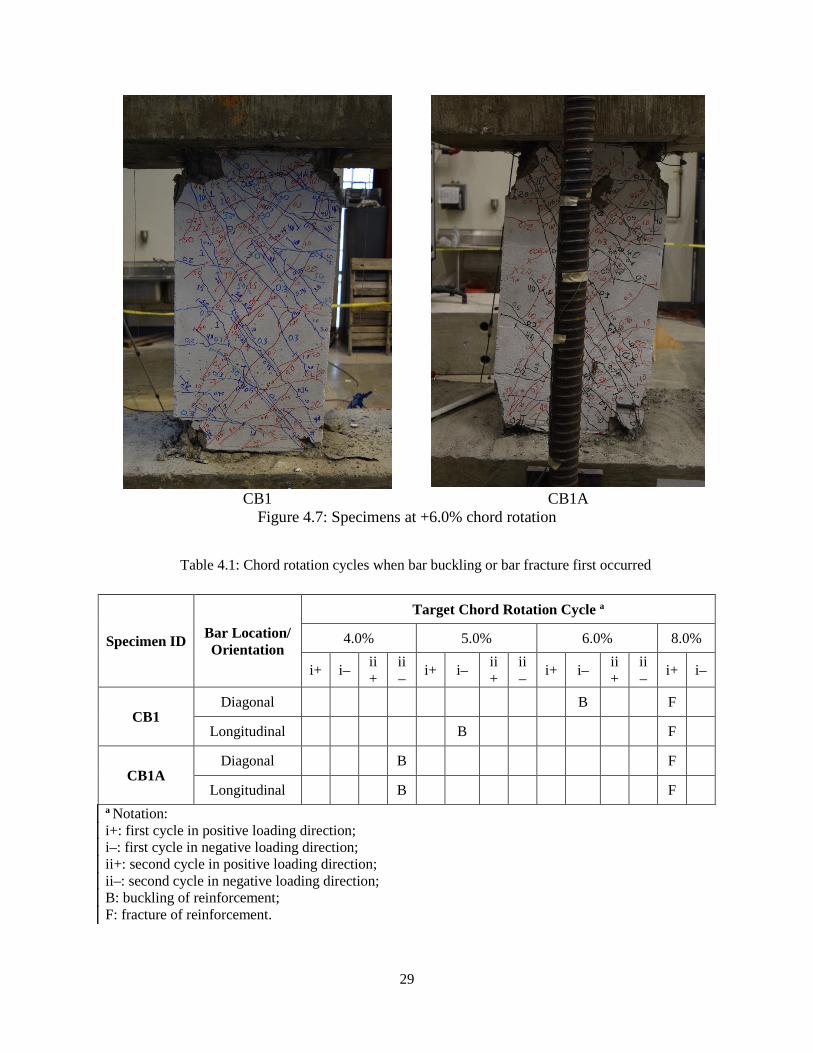
Figure 4.7 shows the condition of the two specimens at a chord rotation of 6.0%. The deformations in both specimens concentrated near the beam-to-wall interface where the diagonal bars buckled and ultimately fractured. This behavior is related to the termination of the longitudinal reinforcement at the intersection of the beam and wall interface (Figure 3.1).
In both specimens, horizontal flexural cracks associated with double curvature bending were observed on the 10-in (25.4-cm) faces of the beams. These horizontal cracks continued onto the 18 in. (45.7-cm) side and formed inclined cracks. In both specimens, the first cracks were observed at a chord rotation of 0.2%. In both specimens, new cracks were not observed after a chord rotation of 4.0%, but existing cracks continued to widen.
As the chord rotation demand increased, the cover concrete started to spall off, followed by buckling and eventual fracture of the diagonal reinforcement. In CB1A, concrete crushing and spalling was first observed at a chord rotation of +2.0% while in CB1 crushing was not observed until a chord rotation of +3.0% was reached. Table 4.1 identifies the target chord rotation cycles where bar buckling or bar fracture was first observed for each specimen for both diagonal and longitudinal bars. Buckling of diagonal reinforcement was first observed in CB1 during the first cycle to a chord rotation of -6.0% and in CB1A during the second cycle to a chord rotation of -4.0%. In both specimens fracture of diagonal reinforcement was first observed during the second cycle to +8.0% chord rotation.
29
CB1 CB1A
Figure 4.7: Specimens at +6.0% chord rotation
Table 4.1: Chord rotation cycles when bar buckling or bar fracture first occurred
Specimen ID Bar Location/ Orientation
Target Chord Rotation Cycle a
4.0% 5.0% 6.0% 8.0%
i+ i– ii+
ii– i+ i– ii
+ ii– i+ i– ii
+ ii– i+ i–
CB1 Diagonal B F
Longitudinal B F
CB1A Diagonal B F
Longitudinal B F a Notation: i+: first cycle in positive loading direction; i–: first cycle in negative loading direction; ii+: second cycle in positive loading direction; ii–: second cycle in negative loading direction; B: buckling of reinforcement; F: fracture of reinforcement.
30
The presence of axial restraint did not have a significant impact on the failure mechanism of the beam. Both beams failed by bar buckling followed by fracture of the diagonal reinforcing bars. However, CB1A, which had axial restraints, exhibited crushing of concrete and reinforcement buckling at smaller chord rotations.
4.4 BEAM ELONGATION AND AXIAL FORCE
4.4.1 BEAM ELONGATION
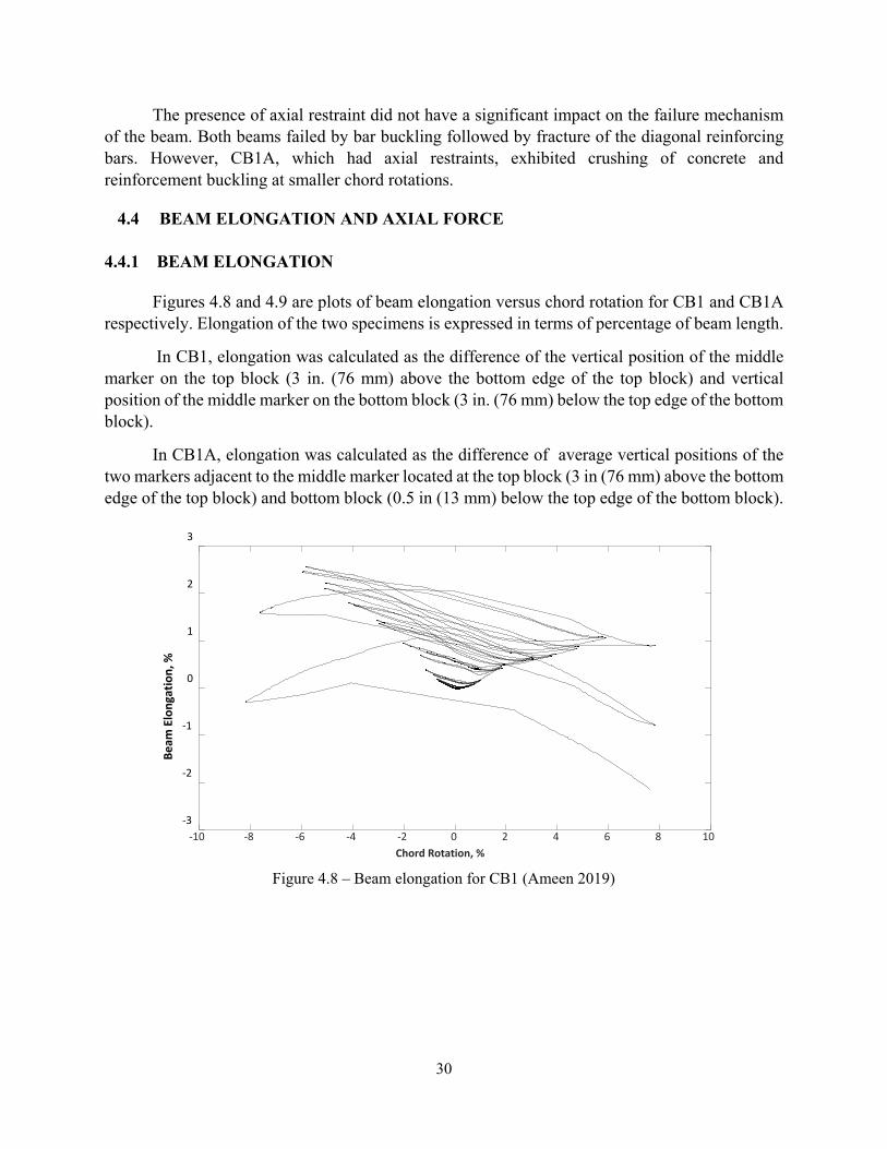
Figures 4.8 and 4.9 are plots of beam elongation versus chord rotation for CB1 and CB1A respectively. Elongation of the two specimens is expressed in terms of percentage of beam length.
In CB1, elongation was calculated as the difference of the vertical position of the middle marker on the top block (3 in. (76 mm) above the bottom edge of the top block) and vertical position of the middle marker on the bottom block (3 in. (76 mm) below the top edge of the bottom block).
In CB1A, elongation was calculated as the difference of average vertical positions of the two markers adjacent to the middle marker located at the top block (3 in (76 mm) above the bottom edge of the top block) and bottom block (0.5 in (13 mm) below the top edge of the bottom block).
Figure 4.8 – Beam elongation for CB1 (Ameen 2019)
-10 -8 -6 -4 -2 0 2 4 6 8 10Chord Rotation, %
-3
-2
-1
0
1
2
3
Beam
Elo
ngat
ion,
%

31
Figure 4.9 – Beam elongation for CB1A
Figure 4.8 shows that CB1 elongated up to 2.5%, with the maximum elongation occurring at a chord rotation of -6.0%. While loading to 8% chord rotation, the beam started to shorten as damage became severe. Figure 4.9 shows the elongation of specimen CB1A, which had a maximum of approximately 1.0%. The presence of the axial restraint therefore caused CB1A to exhibit much less elongation than CB1 at large chord rotations.
4.4.2 Axial Force
4.4.2.1 MEASURED VALUES
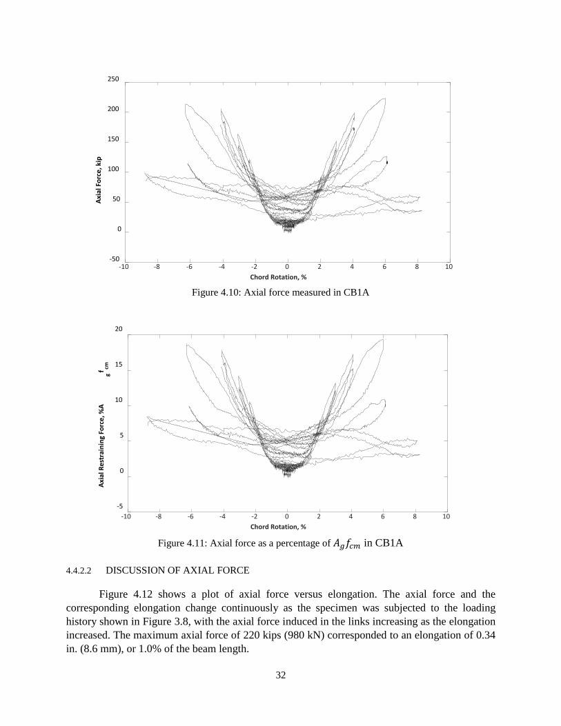
The resistance to elongation induced an axial compression force in CB1A. The axial force was estimated, assuming zero force at the start of the test, based on data from the strain gauges on the axial restraint system described in Chapter 3. The measured strain was converted to force in each rod assuming a modulus of 29,000 ksi (200 GPa) for the steel and a rod area equal to the nominal area provided by the manufacturer. Total force in the beam was then taken as the sum of forces in the two rods, which were approximately equal throughout the test. The axial force in the beam is plotted in Figure 4.10 versus chord rotation. The maximum restraining force was approximately 220 kips (980 kN), which occurred at a chord rotation of + 6.0%. Figure 4.10 also shows that axial force was relatively small (less than 60 kips [267 kN]) at chord rotations up to approximately 1.5%, and large for chord rotations between approximately 4.0% and 6.0%.
Figure 4.11 shows the axial restraining force expressed as a percentage of 𝐴𝐴𝑔𝑔𝑓𝑓𝑐𝑐𝑐𝑐, where 𝐴𝐴𝑔𝑔 is the gross cross-sectional area of the coupling beam and 𝑓𝑓𝑐𝑐𝑐𝑐 is the concrete compressive strength at test day. The figure shows that the maximum restraining force developed was nearly 19% of 𝐴𝐴𝑔𝑔𝑓𝑓𝑐𝑐𝑐𝑐, a magnitude large enough that increases in member strength and decreases in deformation capacity would reasonably be expected.
-10 -8 -6 -4 -2 0 2 4 6 8 10Chord Rotation, %
-3
-2
-1
0
1
2
3
Beam
Elo
ngat
ion,
%
32
Figure 4.10: Axial force measured in CB1A
Figure 4.11: Axial force as a percentage of 𝐴𝐴𝑔𝑔𝑓𝑓𝑐𝑐𝑐𝑐 in CB1A
4.4.2.2 DISCUSSION OF AXIAL FORCE
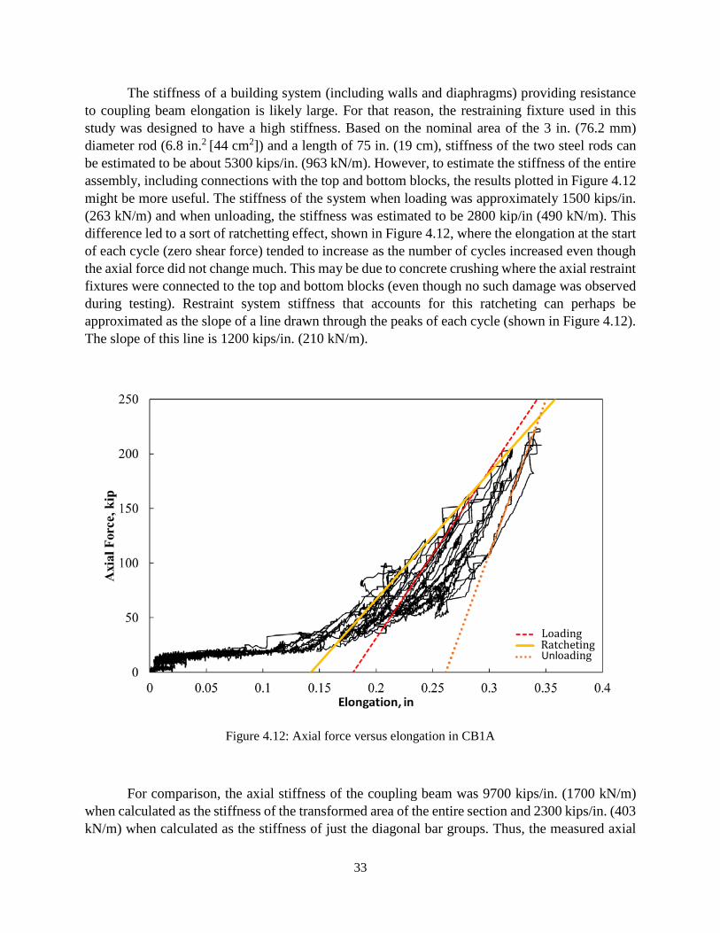
Figure 4.12 shows a plot of axial force versus elongation. The axial force and the corresponding elongation change continuously as the specimen was subjected to the loading history shown in Figure 3.8, with the axial force induced in the links increasing as the elongation increased. The maximum axial force of 220 kips (980 kN) corresponded to an elongation of 0.34 in. (8.6 mm), or 1.0% of the beam length.
-10 -8 -6 -4 -2 0 2 4 6 8 10Chord Rotation, %
-50
0
50
100
150
200
250
Axia
l For
ce, k
ip
-10 -8 -6 -4 -2 0 2 4 6 8 10Chord Rotation, %
-5
0
5
10
15
20
Axia
l Res
trai
ning
For
ce, %
Ag
f cm
33
The stiffness of a building system (including walls and diaphragms) providing resistance to coupling beam elongation is likely large. For that reason, the restraining fixture used in this study was designed to have a high stiffness. Based on the nominal area of the 3 in. (76.2 mm) diameter rod (6.8 in.2 [44 cm2]) and a length of 75 in. (19 cm), stiffness of the two steel rods can be estimated to be about 5300 kips/in. (963 kN/m). However, to estimate the stiffness of the entire assembly, including connections with the top and bottom blocks, the results plotted in Figure 4.12 might be more useful. The stiffness of the system when loading was approximately 1500 kips/in. (263 kN/m) and when unloading, the stiffness was estimated to be 2800 kip/in (490 kN/m). This difference led to a sort of ratchetting effect, shown in Figure 4.12, where the elongation at the start of each cycle (zero shear force) tended to increase as the number of cycles increased even though the axial force did not change much. This may be due to concrete crushing where the axial restraint fixtures were connected to the top and bottom blocks (even though no such damage was observed during testing). Restraint system stiffness that accounts for this ratcheting can perhaps be approximated as the slope of a line drawn through the peaks of each cycle (shown in Figure 4.12). The slope of this line is 1200 kips/in. (210 kN/m).
Figure 4.12: Axial force versus elongation in CB1A
For comparison, the axial stiffness of the coupling beam was 9700 kips/in. (1700 kN/m) when calculated as the stiffness of the transformed area of the entire section and 2300 kips/in. (403 kN/m) when calculated as the stiffness of just the diagonal bar groups. Thus, the measured axial
Loading
Unloading
Ratcheting
34
stiffness of the two diagonal bar groups is about 1/4 of the stiffness of the gross section of the coupling beam.
The maximum recorded axial force was 220 kips (980 kN). This is equal to 110% of the longitudinal component of 𝐴𝐴𝑠𝑠𝑓𝑓𝑦𝑦 for one diagonal bar group based on an area of 3.6 in.2 (23 cm2)
and a yield stress of 60 ksi (414 MPa). A similar relationship is present in data obtained from tests of fiber-reinforced coupling beams with reduced amounts of diagonal bars (Lequesne, 2011). In those tests, axial forces of approximately 70 kips (311 kN) developed at large chord rotations. This was equivalent to 71 kip (315 kN), the product of tension steel area (1.19 in.2 [7.7 cm2]) and specified yield stress (60 ksi [414 MPa]). However, it is difficult to conclude with certainty whether the strength of a group of diagonal bars provides a safe estimate of beam axial forces based on the very limited data.
4.5 BEAM STRENGTH
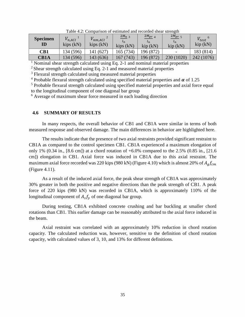
Table 4.2 shows the shear strength of the coupling beams calculated with Eq. 2-1 using nominal and measured properties, shear force corresponding to nominal moment strength and probable moment strength at the beam ends, and the average of recorded peak strengths in the positive and negative loading directions. Nominal shear strength, 𝑉𝑉𝑛𝑛,𝐴𝐴𝐴𝐴𝐴𝐴, was calculated using specified material properties (𝑓𝑓𝑦𝑦 = 60 ksi, [414 MPa]) and 𝑉𝑉𝑛𝑛𝑐𝑐,𝐴𝐴𝐴𝐴𝐴𝐴 was calculated using properties obtained from tensile testing of reinforcing bars (𝑓𝑓𝑦𝑦 = 64 ksi, [441 MPa]). Nominal moment strength, 𝑀𝑀𝑛𝑛, was calculated using measured material properties and probable moment strength, 𝑀𝑀𝑡𝑡𝑝𝑝 , was calculated using specified properties with an overstrength factor of 1.25. The following assumptions were made in flexural strength calculations: 1) contribution of horizontal bars, cutoff near the wall face, to beam flexural strength was neglected; 2) the longitudinal component of the diagonal bar group area (3.4 in.2 [22 cm2]) was used to calculate the moment strength; 3) beams were assumed to be doubly reinforced; and 4) axial force was neglected (except for column 5 where flexural strength was calculated assuming an axial force equal to the longitudinal component of one diagonal bar group acting along the centroid of the beam).
The recorded peak shear force was greater than the shear strength calculated using either the nominal or measured material properties by about 35% and 75% in CB1 and CB1A, respectively. The recorded shear strength was greater than the shear strength calculated using nominal moment strength by 10% and 45% in CB1 and CB1A respectively, showing again (Lequesne, 2011) that use of nominal moment provides a more accurate estimate of beam strength than Eq. 2-1. Beam strength calculated based on the probable moment strength overestimated the recorded strength for CB1 by 7% and underestimated the strength for CB1A by 23%. The most accurate calculation of strength for CB1A was based on the probable moment strength calculated using specified material properties and assuming an axial force equal to the longitudinal component of one diagonal bar group. The measured strength exceed this calculated value by only 5%.
35
Table 4.2: Comparison of estimated and recorded shear strength
Specimen ID
𝑉𝑉𝑛𝑛,𝐴𝐴𝐴𝐴𝐴𝐴 1 kips (kN)
𝑉𝑉𝑛𝑛𝑐𝑐,𝐴𝐴𝐴𝐴𝐴𝐴 2 kips (kN)
2𝑀𝑀𝑛𝑛𝑙𝑙𝑛𝑛
3 kips (kN)
2𝑀𝑀𝑝𝑝𝑝𝑝
𝑙𝑙𝑛𝑛 4
kip (kN)
2𝑀𝑀𝑝𝑝𝑝𝑝
𝑙𝑙𝑛𝑛 5
kip (kN) 𝑉𝑉𝑡𝑡𝑡𝑡𝑠𝑠𝑡𝑡 6
kip (kN) CB1 134 (596) 141 (627) 165 (734) 196 (872) - 183 (814)
CB1A 134 (596) 143 (636) 167 (743) 196 (872) 230 (1020) 242 (1076) 1 Nominal shear strength calculated using Eq. 2-1 and nominal material properties 2 Shear strength calculated using Eq. 2-1 and measured material properties
3 Flexural strength calculated using measured material properties 4 Probable flexural strength calculated using specified material properties and 𝜶𝜶 of 1.25 5 Probable flexural strength calculated using specified material properties and axial force equal to the longitudinal component of one diagonal bar group 6 Average of maximum shear force measured in each loading direction
4.6 SUMMARY OF RESULTS
In many respects, the overall behavior of CB1 and CB1A were similar in terms of both measured response and observed damage. The main differences in behavior are highlighted here.
The results indicate that the presence of two axial restraints provided significant restraint to CB1A as compared to the control specimen CB1. CB1A experienced a maximum elongation of only 1% (0.34 in., [8.6 cm]) at a chord rotation of +6.0% compared to the 2.5% (0.85 in., [21.6 cm]) elongation in CB1. Axial force was induced in CB1A due to this axial restraint. The maximum axial force recorded was 220 kips (980 kN) (Figure 4.10) which is almost 20% of 𝐴𝐴𝑔𝑔𝑓𝑓𝑐𝑐𝑐𝑐 (Figure 4.11).
As a result of the induced axial force, the peak shear strength of CB1A was approximately 30% greater in both the positive and negative directions than the peak strength of CB1. A peak force of 220 kips (980 kN) was recorded in CB1A, which is approximately 110% of the longitudinal component of 𝐴𝐴𝑠𝑠𝑓𝑓𝑦𝑦 of one diagonal bar group.
During testing, CB1A exhibited concrete crushing and bar buckling at smaller chord rotations than CB1. This earlier damage can be reasonably attributed to the axial force induced in the beam.
Axial restraint was correlated with an approximately 10% reduction in chord rotation capacity. The calculated reduction was, however, sensitive to the definition of chord rotation capacity, with calculated values of 3, 10, and 13% for different definitions.
36
CHAPTER 5: SUMMARY AND CONCLUSIONS
5.1 SUMMARY
Reinforced concrete structural walls are commonly used to resist lateral loads in mid- and high-rise buildings. These walls are often pierced with openings to accommodate doors and windows. This results in two or more walls being connected by a series of coupling beams along their height. The main purpose of these beams is to restore strength and stiffness of the wall system lost due to the openings.
Under displacement reversals, coupling beams have a tendency to elongate due to concrete cracking and reinforcing bar yielding. Diaphragms and adjacent walls that have very high in-plane stiffness restrict this elongation. Axial forces are therefore induced in the beam that might influence beam strength and deformation capacity.
No studies were found that directly evaluate experimentally the effects of axial restraint provided by structural walls and diaphragms on the deformation capacity and strength of diagonally reinforced concrete coupling beams. The magnitude of axial force and the mechanism causing the development of these axial forces have received little attention. Axial forces on coupling beams are therefore often ignored in analysis and design of coupling beams and coupled walls. The main objective of this study was to evaluate the influence of axial restraint on the strength and deformation capacity of diagonally reinforced concrete coupling beams.
For this project, an axially restrained diagonally reinforced concrete coupling beam was designed, constructed, and tested under fully reversed cyclic loading. The results were compared in terms of strength, deformation capacity, elongation, and induced axial force to those of a control specimen, CB1, that was tested without restraints.
5.2 CONCLUSIONS
The fixtures attached to CB1A provided substantial restraint to the beam. CB1A elongated only 1.0% (0.34 in. [8.6 mm]) compared to the 2.5% (0.85 in. [21.6 mm]) elongation of CB1. The induced axial force peaked at 220 kips (980 kN) (19% of 𝐴𝐴𝑔𝑔𝑓𝑓𝑐𝑐′) at 6.0% chord rotation.
CB1A experienced a peak shear force that was approximately 30% larger than CB1, showing that axial restraint resulted in a large increase in member strength. The strength of CB1A was 80% greater than the nominal shear strength calculated using nominal material properties and provisions of Chapter 18 in ACI 318-14 (without a strength-reduction factor). This overstrength should be accounted for in design of systems that may be sensitive to it. Use of a probable flexural strength calculation to estimate beam strength was more accurate, with beam strength exceeding the calculated value by only 5% when axial force was accounted for.
Axial restraint was correlated with an approximately 10% reduction in chord rotation capacity. The calculated reduction was, however, sensitive to the definition of chord rotation capacity. Based on the definition that the chord rotation capacity is the average of the maximum
37
chord rotation imposed in each loading direction without more than 20% reduction in load carrying capacity, the chord rotation capacity of CB1A was 13% lower than the control specimen, CB1. A second definition of chord rotation capacity, based on where the envelope to the first cycle peaks drop below 80% of the peak strength, indicated the chord rotation capacity of CB1A was approximately 3% lower than CB1. A third definition of deformation capacity, based on where the envelope to peaks of each cycle reaching a new chord rotation dropped below 80% of the peak strength, resulted in a chord rotation capacity that was approximately 10% lower than CB1.
The presence of axial restraint had a small impact on the failure mechanism of the coupling beam. Both beams failed after damage to concrete near the beam ends and buckling and fracture of diagonal bars. Concrete damage and bar buckling were observed to occur earlier in the loading history in CB1A than in CB1. For a given chord rotation demand, an axially restrained beam is likely to exhibit more damage.
5.3 FUTURE WORK
Results obtained from this study show that axially restraining a coupling beam can result in large overstrength and a small decrease in deformation capacity. However, the findings are based on results from tests of only two specimens. Further study to quantify the effects of variables such as beam aspect ratio, reinforcement grade, and reinforcement layout may be appropriate.
The axial restraining fixture was designed to be very stiff, but it may not have been representative of the actual restraint provided by adjacent walls and floor diaphragms. Furthermore, coupling beam axial forces due to shifting of wall shear force from the tension wall to the compression wall were not simulated in this study. Results from tests and simulations of large-scale coupled walls with floor diaphragms might be used to estimate the stiffness of the axial restraint actually present in structures and the magnitude of coupling beam axial forces.

38
REFERENCES
ACI 318-05. (2005). “Building Code Requirements for Structural Concrete (ACI 318-05) and
Commentary”. ACI Committee 318, American Concrete Institute, Farmington Hills, Michigan. ACI 318-08. (2008). “Building Code Requirements for Structural Concrete (ACI 318-08) and
Commentary”. ACI Committee 318, American Concrete Institute, Farmington Hills, Michigan. ACI 318-14. (2014). “Building Code Requirements for Structural Concrete (ACI 318-14) and
Commentary”. ACI Committee 318, American Concrete Institute, Farmington Hills, Michigan. Ameen, S. (2019). “Diagonally Reinforced Concrete Coupling Beams with High-Strength Steel
Bars”, Doctoral dissertation, University of Kansas, Lawrence, KS, 343 pp. Ameen S., Lequesne R. D., Lepage A., Weber-Kamin A., and Huq S. (2017). “Behavior Of Diagonally-
Reinforced Concrete Coupling Beams With High-Strength Steel Bars”, 16th World Conference on Earthquake Engineering, Santiago, Chile, 2017.
ASTM A370 (2014). “Standard Test Methods and Definitions for Mechanical Testing of Steel Products,” ASTM International, West Conshocken, PA, 2014.
ASTM A706 (2016). “Standard specifications for Deformed and Plain Low-Alloy Steel Bars for Concrete Reinforcement,” ASTM International, West Conshocken, PA, 2016.
ASTM C39 (2018). “Standard Test Methods for Compressive Strength of Cylindrical Concrete Specimens,” ASTM International, West Conshocken, PA, 2018.
Bower, O. J. (2008). “Analytical Investigation into the Effect of Axial Restraint on the Stiffness and Ductility of Diagonally Reinforced Concrete Coupling Beams”, Doctoral dissertation, University of Cincinnati.
Federal Emergency Management Agency (FEMA) (2007). “FEMA 461: Interim Protocols for Determining Seismic Performance Characteristics of Structural and Nonstructural Components through Laboratory Testing”, Applied Technology Council.
Fortney, P. J., Rassati, G. A., and Shahrooz, B. M. (2008). “Investigation on Effect of Transverse Reinforcement on Performance of Diagonally Reinforced Coupling Beams”, ACI Structural Journal, 105 (6), 781-788.
Galano, L. and Vignoli, A. (2000). “Seismic Behavior of Short Coupling Beams with Different Reinforcement Layouts”, ACI Structural Journal, 97 (6), 876-885.
Harries, K. A., Fortney, P. J., Shahrooz, B.M., and Brienen, P. J. (2005). “Practical Design of Diagonally Reinforced Concrete Coupling Beams – Critical Review of ACI 318 Requirements”, ACI Structural Journal, 102 (6), 876-882.
Irwin, A. W. and Ord, A. E. C. (1976). “Cyclic Load Tests on Shear Wall Coupling Beams”, Proceedings of the Institution of Civil Engineers, Part 1 – Design and Construction, 61 (2), 331-342.
Lequesne, R. D. (2011). “Behavior and Design of High-Performance Fiber-Reinforced Concrete Coupling Beams and Coupled-Wall Systems”, Doctoral Dissertation, University of Michigan.
Lequesne, R. D., Parra-Montesinos, G. J., and Wight, J. K. (2012). “Seismic Behavior and Detailing of High-Performance Fiber-Reinforced Concrete Coupling Beams and Coupled Wall Systems”, Journal of Structural Engineering, 139 (8), 1362-1370.
Lim, E., Hwang, S.-J., Cheng, C.-H., and Lin, P.-Y. (2016). “Cyclic Tests of Reinforced Concrete Coupling Beam with Intermediate Span-Depth Ratio”, ACI Structural Journal, 113 (3), 515-524.
39
Moehle, J. P. (2014). “Seismic Design of Reinforced Concrete Buildings”, McGraw-Hill Education, New York, NY, pp. 760.
Naish, D., Fry, J. A., Klemencic, R., and Wallace, J. (2009). “Reinforced Concrete Link Beams: Alternative Details for Improved Constructability”, Report to Charles Pankow Foundation. UCLA-SGEL, 103 pp.
Park, R. and Paulay, T. (1975). Reinforced Concrete Structures. John Wiley & Sons. Paulay, T. (1969). “The Coupling of Shear Walls”, Doctoral Dissertation, University of Canterbury,
Christchurch, New Zealand. Paulay, T. (1971). “Coupling Beams of Reinforced Concrete Shear Walls,” Journal of the Structural
Division, ASCE, 97 (ST3), 843-861. Paulay, T. and Binney, J. R. (1974). “Diagonally Reinforced Coupling Beams of Shear Walls”, Shear in
Reinforced Concrete, SP-42, American Concrete Institute, Detroit, MI, 2, 579-598. Paulay, T. and Santhakumar, A. R. (1976). “Ductile Behavior of Coupled Shear Walls”, Journal of the
Structural Division, ASCE, 102 (ST1), 93-108. Saatcioglu, M., Derecho, A.T., and Corley, W.G. (1987). “Parametric Study of Earthquake-Resistant
Coupled Walls”, Journal of Structural Engineering, 113 (1), 141-157. Shiu, K. N., Barney, G. B., Fiorato, A. E., and Corley, W. G. (1978). “Reversing Load Tests of Reinforced
Concrete Coupling Beams”, In Proceedings of the Central American Conference on Earthquake Engineering, pp. 239-249.
Smith, B.S. and Coull, A. (1991). “Tall Building Structures – Analysis and Design”, New York: John Wiley & Sons.
Tassios, T. P., Moretti, M., and Bezas, A. (1996). “On the Behavior and Ductility of Reinforced Concrete Coupling Beams of Shear Walls”, ACI Structural Journal, 93 (6), 1-10.
Tegos, I. A. and Penelis, G. G. (1988). “Seismic Resistance of Short Columns and Coupling Beams reinforced with Inclined Bars”, ACI Structural Journal, 85 (1), 82-88.