Embed Size (px)
Citation preview
Part Number 020005256 10/15
DI, DIL, & CT SERIESBeverage Dispensers
Installation, Operation and Maintenance ManualThis manual is updated as new information and models are released. Visit our website for the latest manual.
Safety NoticesAs you work on Manitowoc equipment, be sure to pay close attention to the safety notices in this manual. Disregarding the notices may lead to serious injury and/or damage to the equipment.
Throughout this manual, you will see the following types of safety notices:
nWarningText in a Warning box alerts you to a potential personal injury situation. Be sure to read the Warning statement before proceeding, and work carefully.
,CautionText in a Caution box alerts you to a situation in which you could damage the equipment. Be sure to read the Caution statement before proceeding, and work carefully.
Procedural NoticesAs you work on Manitowoc equipment, be sure to read the procedural notices in this manual. These notices supply helpful information which may assist you as you work.
Throughout this manual, you will see the following types of procedural notices:
�Imortant�Text in an Important box provides you with information that may help you perform a procedure more efficiently. Disregarding this information will not cause damage or injury, but it may slow you down as you work.
NOTE: Text set off as a Note provides you with simple, but useful, extra information about the procedure you are performing.
Read These Before Proceeding:
,CautionProper installation, care and maintenance are essential for maximum performance and trouble-free operation of your Manitowoc equipment. Read and understand this manual. It contains valuable care and maintenance information. If you encounter problems not covered by this manual, do not proceed, contact Manitowoc Foodservice Group. We will be happy to provide assistance.
�Imortant�Routine adjustments and maintenance procedures outlined in this manual are not covered by the warranty.
nWarningPERSONAL �NJURY POTENT�AL
Do not operate equipment that has been misused, abused, neglected, damaged, or altered/modified from that of original manufactured specifications.
NOTE: SAVE THESE INSTRUCTIONS.
Table of Contents
Part Number 020005256 10/15 3
Section 1General Information
Read This Manual ............................................................................................................... 5Unit Inspection ................................................................................................................... 5Model Numbers .................................................................................................................. 5Serial Number Location ..................................................................................................... 6Warranty Information ........................................................................................................ 6
Section 2Installation
General System Overview ................................................................................................. 7Unit Dimensions .....................................................................................................................................9Electrical ................................................................................................................................................. 10
Pre-installation Checklist ................................................................................................12Step by Step Installation..................................................................................................13
Carb/NON-Carb Settings .................................................................................................................. 13Counter top Footprints ..................................................................................................................... 14Placing the Unit .................................................................................................................................... 16Carbonator Purge Tube Routing .................................................................................................... 19Plumbing Diagrams ............................................................................................................................ 20Starting System & Dispenser ........................................................................................................... 29
Section 3Operation
Component Identification ...............................................................................................31Sequence of Operation ....................................................................................................31
Post-Mix Drop-Ins ................................................................................................................................ 31Pre-Mix Drop-Ins .................................................................................................................................. 32Stands ...................................................................................................................................................... 32Cold Plate Beverage Cooling ........................................................................................................... 32Unit Inspection ..................................................................................................................................... 32Beverage Valves ................................................................................................................................... 32CO2 Supply ............................................................................................................................................. 33Carbonated Water ............................................................................................................................... 33Syrup Delivery System ....................................................................................................................... 33Water Supply ......................................................................................................................................... 33Back Room Package ........................................................................................................................... 34Figal System .......................................................................................................................................... 34Figal Tanks .............................................................................................................................................. 35Racking.................................................................................................................................................... 35B-I-B .......................................................................................................................................................... 35Pumps ...................................................................................................................................................... 35Auto Bag Selectors .............................................................................................................................. 35
4 PPart Number 020005256 10/15
Table of Contents (continued)
Section 4Maintenance
Cleaning ............................................................................................................................37Disassemble for Cleaning ................................................................................................................. 37Daily Cleaning....................................................................................................................................... 37Monthly Cleaning ................................................................................................................................ 38Cleaning Checklist .............................................................................................................................. 38Preventive Maintenance ................................................................................................................... 38
Sanitizing ..........................................................................................................................39Beverage System Cleaning .............................................................................................................. 39Bag-In-Box System Sanitation ........................................................................................................ 39Figal Beverage System ....................................................................................................................... 40Figal Beverage System ....................................................................................................................... 41
Shipping, Storage and Relocation ..................................................................................41
Section 5Before Calling for Service
Checklist ............................................................................................................................43Drink Troubleshooting ...................................................................................................................... 43
Pump Troubleshooting ....................................................................................................44
Part Number 020005256 10/15 5
Read This ManualManitowoc Beverage Systems developed this manual as a reference guide for the owner/operator and installer of this equipment. Please read this manual before installation or operation of the machine. A qualified service technician must perform installation and start-up of this equipment, consult Section 5 within this manual for service assistance.
If you cannot correct the service problem, call your MBS Service Agent or Distributor. Always have your model and serial number available when you call.
Your Service Agent
Service Agent Telephone Number
Your Local MBE Distributor
Distributor Telephone Number
Model Number
Serial Number
Installation Date
Unit Inspection
Unit InspectionThoroughly inspect the unit upon delivery. Immediately report any damage that occurred during transportation
to the delivery carrier. Request a written inspection report from a claims inspector to document any necessary claim.
n WarningPERSONAL INJURY POTENTIAL
Do not operate equipment that has been misused, abused, neglected, damaged, or altered/modified from that of original manufactured specifications.
Model NumbersThis manual covers the following models:
Beverage Dispensers
CT-6, CT-8, DI-1522, DI-2323, DIL-2323
Section 1General Information
General Information Section 1
6 Part Number 020005256 5/15
Serial Number LocationThis number is required when requesting information from your local distributor. The serial number is listed on the SERIAL NUMBER DECAL affixed to the dispenser.
Warranty InformationConsult your local MBS Distributor for terms and conditions of your warranty. Your warranty specifically excludes all beverage valve brixing, general adjustments, cleaning, accessories and related servicing.
Your warranty card must be returned to MBS to activate the warranty on this equipment. If a warranty card is not returned, the warranty period can begin when the equipment leaves the MBS factory.
No equipment may be returned to MBS without a written Return Materials Authorization (RMA). Equipment returned without an RMA will be refused at MBS’s dock and returned to the sender at the sender’s expense.
Please contact your local MBS distributor for return procedures.
Part Number 020005256 10/15 7
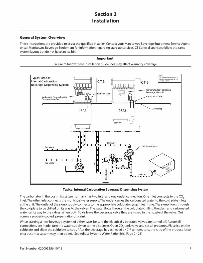
General System OverviewThese instructions are provided to assist the qualified installer. Contact your Manitowoc Beverage Equipment Service Agent or call Manitowoc Beverage Equipment for information regarding start-up services. CT Series dispensers follow the same system layout but do not have an ice bin.
�mmprtant�Failure to follow these installation guidelines may affect warranty coverage.
Tymical �nternal Carbpnatipn Beverage Dismensing System
1800 75
SYRUP
CO2
CO
2 C
ylin
der
CO
2
SYRUP
60
Tap Water
Tap Water
Typical Drop-In Internal Carbonation Beverage Dispensing System
Bag-In-Box
Syrup
Carton
BIB Syrup Pump
NOTE: This is a simplified schematic to show the basic operation of the beverage system.
Countertop
CT-8
1522 2323
CT-6
Carbonator TankCarbonate, Non-carbonate Beverage Manifold
Carbonate, Non-carbonate Beverage Manifold
Carbonator Tank
The carbonator in the post-mix system normally has two inlet and one outlet connection. One inlet connects to the CO2 inlet. The other inlet connects the municipal water supply. The outlet carries the carbonated water to the cold plate inlets at the unit. The outlet of the syrup supply connects to the appropriate coldplate syrup inlet fitting. The syrup flows through the coldplate to be chilled on its way to the valves. The water flows through the coldplate chilling the plain and carbonated water on its way to the valves. When both fluids leave the beverage valve they are mixed in the nozzle of the valve. Out comes a properly cooled, proper ratio soft drink.
When starting a new beverage system of either type, be sure the electrically operated valves are turned off. Assure all connections are made, turn the water supply on to the dispenser. Open CO2 tank valve and set all pressures. Place ice on the coldplate and allow the coldplate to cool. After the beverage has achieved a 40°F temperature, the ratio of the product (brix) on a post-mix system may then be set. (See Adjust Syrup to Water Ratio (Brix) Page 2 - 21)
Sectipn 2�nstallatipn
8 Part Number 020005256 10/15
Installation Section 2
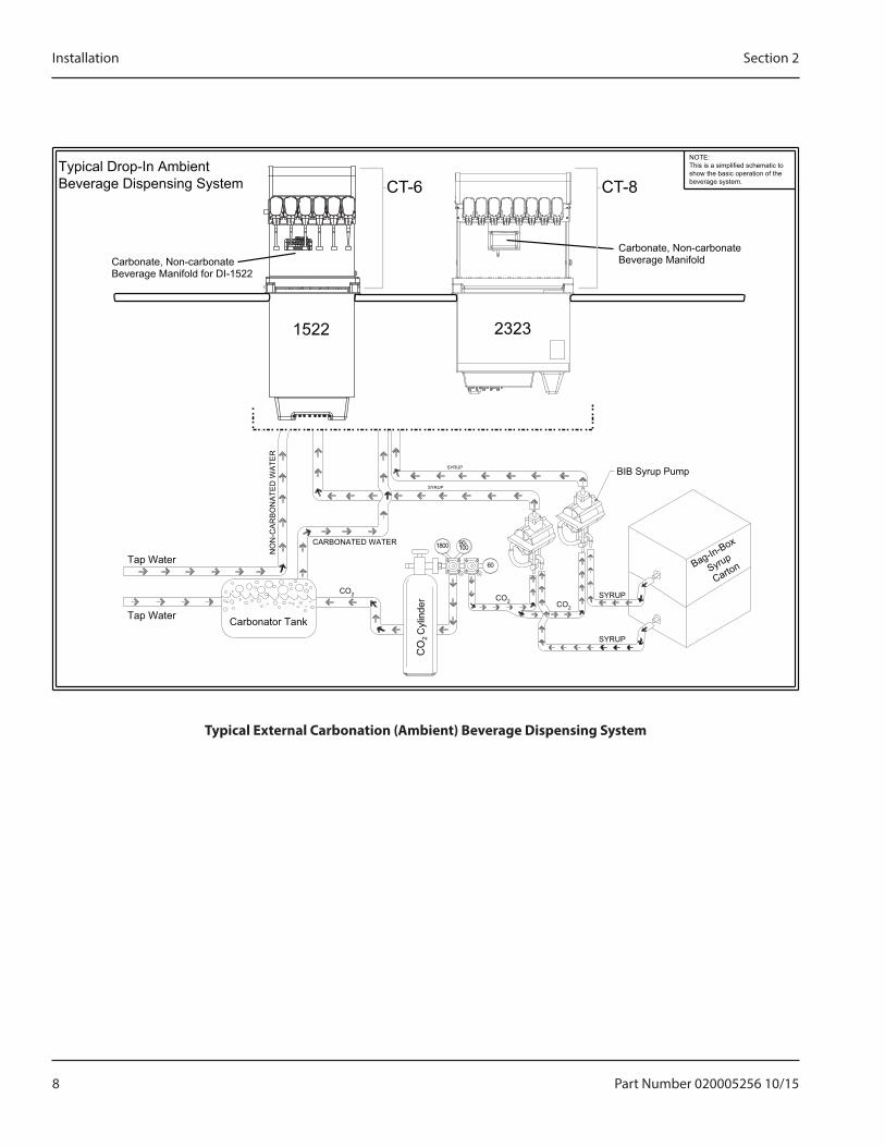
Tymical External Carbpnatipn (Ambient) Beverage Dismensing System
Typical Drop-In Ambient Beverage Dispensing System
90-1800
60
100
CO2 CO2 CO2
SYRUP
CARBONATED WATER
NO
N-C
AR
BO
NA
TED
WA
TER
SYRUP
SYRUP
SYRUP
Carbonator TankTap Water
Tap Water
Carbonate, Non-carbonateBeverage Manifold for DI-1522
23231522
NOTE: This is a simplified schematic to show the basic operation of the beverage system.
Carbonate, Non-carbonate Beverage Manifold
BIB Syrup Pump
CO
2 C
ylin
der
Bag-In-Box
Syrup
Carton
CT-6 CT-8
Part Number 020005256 10/15 9
Section 2 Installation
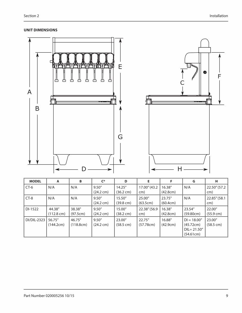
UN�T D�MENS�ONS
B
A
E
G
D H
CF
MODEL A B C* D E F G H
CT-6 N/A N/A 9.50”(24.2 cm)
14.25”(36.2 cm)
17.00” (43.2 cm)
16.38" (42.8cm)
N/A 22.50” (57.2 cm)
CT-8 N/A N/A 9.50”(24.2 cm)
15.50”(39.8 cm)
25.00” (63.5cm)
23.75" (60.4cm)
N/A 22.85” (58.1 cm)
DI-1522 44.38” (112.8 cm)
38.38" (97.5cm)
9.50”(24.2 cm)
15.00”(38.2 cm)
22.38” (56.9 cm)
16.38" (42.8cm)
23.54” (59.80cm)
22.00”(55.9 cm)
DI/DIL-2323 56.75” (144.2cm)
46.75" (118.8cm)
9.50”(24.2 cm)
23.00”(58.5 cm)
22.75” (57.78cm)
16.88" (42.9cm)
DI = 18.00” (45.72cm)DIL= 21.50”(54.61cm)
23.00”(58.5 cm)
10 Part Number 020005256 10/15
Installation Section 2
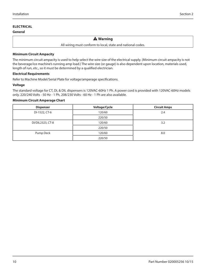
ELECTR�CALGeneral
n WarningAll wiring must conform to local, state and national codes.
Minimum Circuit Ammacity
The minimum circuit ampacity is used to help select the wire size of the electrical supply. (Minimum circuit ampacity is not the beverage/ice machine’s running amp load.) The wire size (or gauge) is also dependent upon location, materials used, length of run, etc., so it must be determined by a qualified electrician.
Electrical Requirements
Refer to Machine Model/Serial Plate for voltage/amperage specifications.
Vpltage
The standard voltage for CT, DI, & DIL dispensers is 120VAC-60Hz 1 Ph. A power cord is provided with 120VAC-60Hz models only. 220/240 Volts - 50 Hz - 1 Ph, 208/230 Volts - 60 Hz - 1 Ph are also available.
Minimum Circuit Ammerage Chart
Dismenser Vpltage/Cycle Circuit Amms
DI-1522, CT-6 120/60 2.4
220/50
DI/DIL2323, CT-8 120/60 3.2
220/50
Pump Deck 120/60 8.0
220/50

Part Number 020005256 10/15 11
Section 2 Installation
Grpunding �nstructipns
This appliance must be grounded. In the event of malfunction or breakdown, grounding provides a path of least resistance for electric current to reduce the risk of electric shock.
n WarningRisk of electrical shock. Connect to a properly grounded outlet only.
This appliance is equipped with a cord having an equipment-grounding conductor and a grounding plug. The plug must be plugged into an appropriate outlet that is properly installed and grounded in accordance with all local codes and ordinances.
n WarningImproper connection of the equipment-grounding conductor can result in a risk of electric shock. The conductor with insulation having an outer surface that is green with or without yellow stripes is the equipment grounding conductor. If repair or replacement of the cord or plug is necessary, do not connect the equipment-grounding conductor to a live terminal. Check with a qualified electrician or serviceman if the grounding instructions are not completely understood, or if in doubt as to whether the appliance is properly grounded. Do not modify the plug provided with the appliance — if it will not fit the outlet, have a proper outlet installed by a qualified electrician.
nWarningWhen using electric appliances, basic precautions should always be followed, including the following:
a. Read all the instructions before using the appliance.
b. To reduce the risk of injury, close supervision is necessary when an appliance is used near children.
c. Do not contact moving parts.d. Only use attachments recommended or sold by
the manufacturer.e. Do not use outdoors.f. For a cord-connected appliance, the following
shall be included:• Do not unplug by pulling on cord. To unplug,
grasp the plug, not the cord.• Unplug from outlet when not in use and
before servicing or cleaning.• Do not operate any appliance with a
damaged cord or plug, or after the appliance malfunctions or is dropped or damaged in any manner. Contact the nearest authorized service facility for examination, repair, or electrical or mechanical adjustment.
g. For a permanently connected appliance — Turn the power switch to the off position when the appliance is not in use and before servicing or cleaning.
h. For an appliance with a replaceable lamp — Always unplug before replacing the lamp. Replace the bulb with the same type.
i. For a grounded appliance — Connect to a properly grounded outlet only. See Grounding Instructions.
12 Part Number 020005256 10/15
Installation Section 2
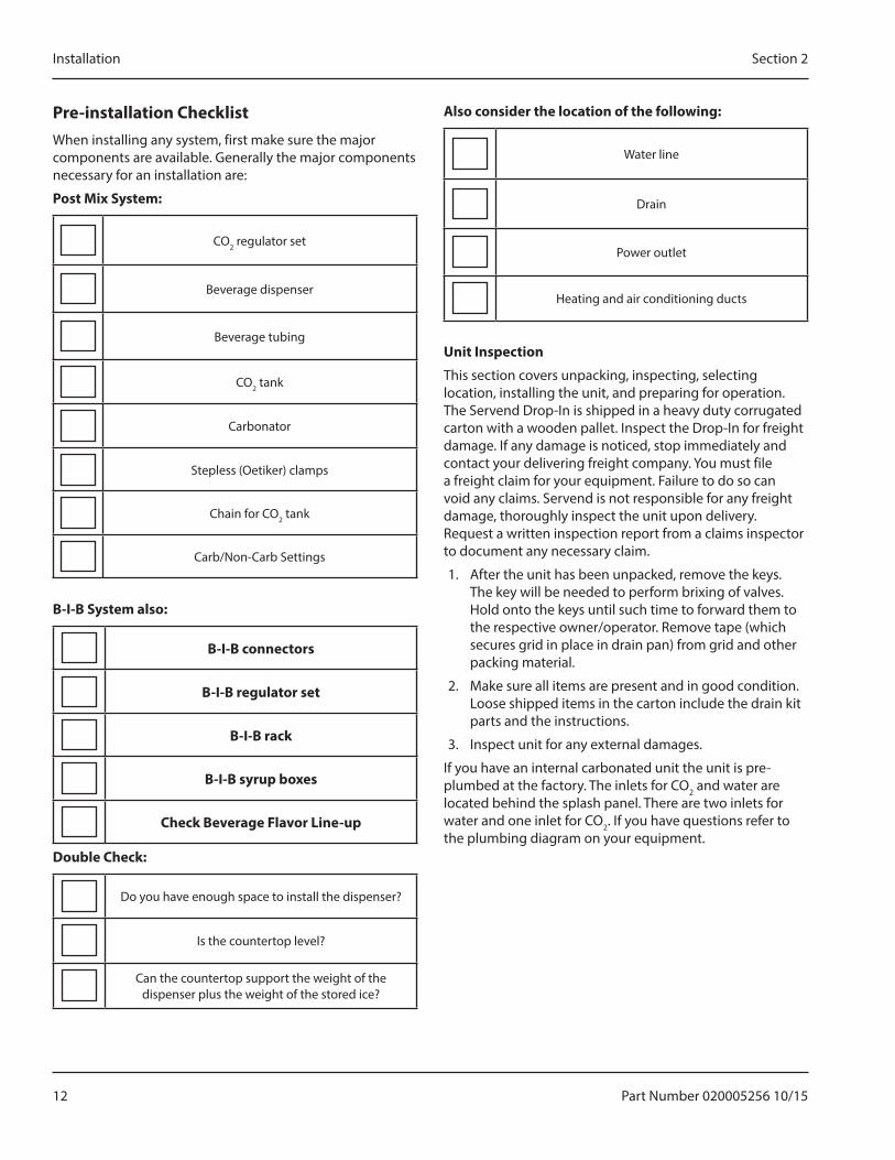
Pre-installatipn ChecklistWhen installing any system, first make sure the major components are available. Generally the major components necessary for an installation are:
Ppst Mix System:
CO2 regulator set
Beverage dispenser
Beverage tubing
CO2 tank
Carbonator
Stepless (Oetiker) clamps
Chain for CO2 tank
Carb/Non-Carb Settings
B-�-B System alsp:
B-�-B cpnnectprs
B-�-B regulatpr set
B-�-B rack
B-�-B syrum bpxes
Check Beverage Flavpr Line-um
Dpuble Check:
Do you have enough space to install the dispenser?
Is the countertop level?
Can the countertop support the weight of the dispenser plus the weight of the stored ice?
Alsp cpnsider the lpcatipn pf the fpllpwing:
Water line
Drain
Power outlet
Heating and air conditioning ducts
Unit �nsmectipn
This section covers unpacking, inspecting, selecting location, installing the unit, and preparing for operation. The Servend Drop-In is shipped in a heavy duty corrugated carton with a wooden pallet. Inspect the Drop-In for freight damage. If any damage is noticed, stop immediately and contact your delivering freight company. You must file a freight claim for your equipment. Failure to do so can void any claims. Servend is not responsible for any freight damage, thoroughly inspect the unit upon delivery. Request a written inspection report from a claims inspector to document any necessary claim.
1. After the unit has been unpacked, remove the keys. The key will be needed to perform brixing of valves. Hold onto the keys until such time to forward them to the respective owner/operator. Remove tape (which secures grid in place in drain pan) from grid and other packing material.
2. Make sure all items are present and in good condition. Loose shipped items in the carton include the drain kit parts and the instructions.
3. Inspect unit for any external damages.
If you have an internal carbonated unit the unit is pre-plumbed at the factory. The inlets for CO2 and water are located behind the splash panel. There are two inlets for water and one inlet for CO2. If you have questions refer to the plumbing diagram on your equipment.
Part Number 020005256 10/15 13
Section 2 Installation
�ncpming Water Summly Requirements
Manitowoc Beverage Equipment recommends that a water shutoff valve and water filter be installed in the incoming water supply line.
The incoming water source to the equipment shall be installed with adequate backflow protection to comply with applicable National, State, and local codes.
Water pressure should be a minimum of 45 psi or you will starve the pump of water and damage it. The maximum water pressure should be 55 psi or you will affect the quality of the carbonation.
The carbonator pump should be located within 6 feet of a 1/2 inch water source. A minimum 3/8 inch ID water line must be used. Before connection the water source should be flushed of approximately 5 gallons of water to purge the system of any sediments, especially in areas of new construction.
Lpcatipn
Avoid placing the dispenser near heat sources such as radiators, ovens, refrigeration equipment and direct sunlight. Optimum Ambient Conditions are between 50°F and 95°F (10°C and 35°C).
Stem by Stem �nstallatipnTo properly install the Servend Drop-In, Use these guidelines:
• Meet all local code requirements.
�mmprtant�The unit must be sealed to the counter to comply with NSF requirements.
• Have a receptacle with the proper voltage at the installation site for connection to the Drop-In.
• Completely unpack the Drop-In, removing all padding and shipping retainers.
• Route the beverage tubing from the syrup racks to the location of the Drop-In.
• Make all beverage connections, if necessary, at the syrup racks.
• Double check countertop cut out dimensions before cutting countertop.
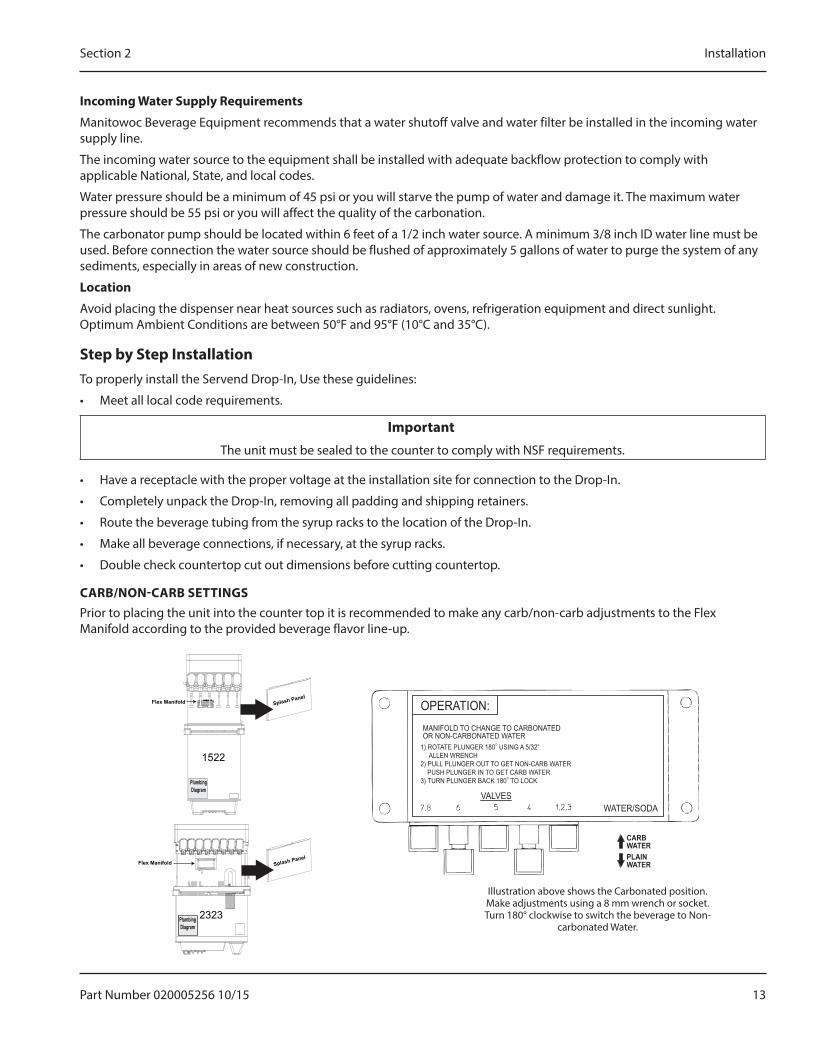
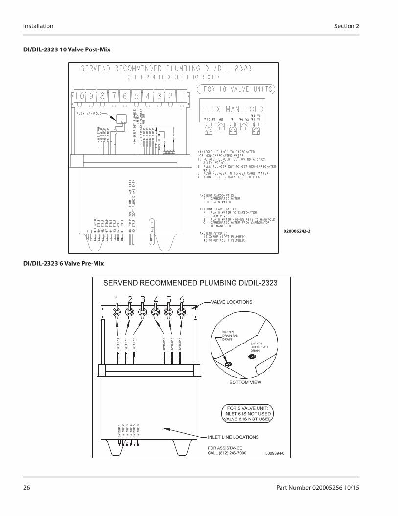
CARB/NON-CARB SETT�NGSPrior to placing the unit into the counter top it is recommended to make any carb/non-carb adjustments to the Flex Manifold according to the provided beverage flavor line-up.
OPERATION:MANIFOLD TO CHANGE TO CARBONATEDOR NON-CARBONATED WATER
VALVES
CARB WATER
WATER/SODA
PLAINWATER
1) ROTATE PLUNGER 180O USING A 5/32” ALLEN WRENCH2) PULL PLUNGER OUT TO GET NON-CARB WATER. PUSH PLUNGER IN TO GET CARB WATER3) TURN PLUNGER BACK 180O TO LOCK
Illustration above shows the Carbonated position. Make adjustments using a 8 mm wrench or socket. Turn 180° clockwise to switch the beverage to Non-
carbonated Water.
Flex Manifold
1522
Plumbing Diagram
Plumbing Diagram
Flex Manifold
2323
14 Part Number 020005256 10/15
Installation Section 2
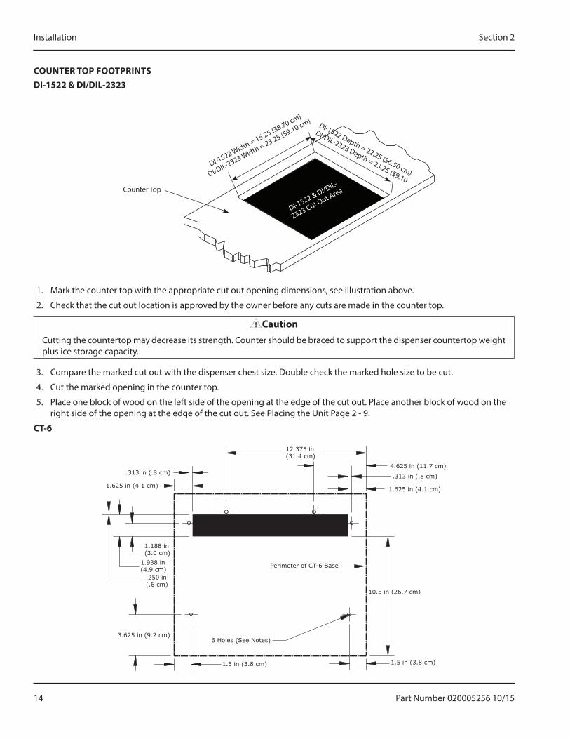
COUNTER TOP FOOTPR�NTSD�-1522 & D�/D�L-2323
Counter Top
DI-1522 Width = 15.25 (38.70 cm)
DI/DIL-2323 Width = 23.25 (59.10 cm)
DI-1522 & DI/DIL-
2323 Cut Out Area
DI-1522 Depth = 22.25 (56.50 cm)
DI/DIL-2323 Depth = 23.25 (59.10
1. Mark the counter top with the appropriate cut out opening dimensions, see illustration above.
2. Check that the cut out location is approved by the owner before any cuts are made in the counter top.
,CautipnCutting the countertop may decrease its strength. Counter should be braced to support the dispenser countertop weight plus ice storage capacity.
3. Compare the marked cut out with the dispenser chest size. Double check the marked hole size to be cut.
4. Cut the marked opening in the counter top.
5. Place one block of wood on the left side of the opening at the edge of the cut out. Place another block of wood on the right side of the opening at the edge of the cut out. See Placing the Unit Page 2 - 9.
CT-6
12.375 in (31.4 cm)
4.625 in (11.7 cm)
.313 in (.8 cm)
1.625 in (4.1 cm)
.313 in (.8 cm)
10.5 in (26.7 cm)
1.5 in (3.8 cm)1.5 in (3.8 cm)
3.625 in (9.2 cm)
1.625 in (4.1 cm)
1.188 in (3.0 cm)
1.938 in (4.9 cm)
.250 in (.6 cm)
Perimeter of CT-6 Base
6 Holes (See Notes)
Part Number 020005256 10/15 15
Section 2 Installation
1. The CT-6 tower has (6) .250 inch diameter mounting holes in the base.
2. Diameter of the 6 holes to be drilled in the countertop depends on fasteners being used to secure tower.
3. The correct counter top hole size if screws are used is .125 inches.
4. The correct counter top hole size if bolts and nuts are used is .250 inches.
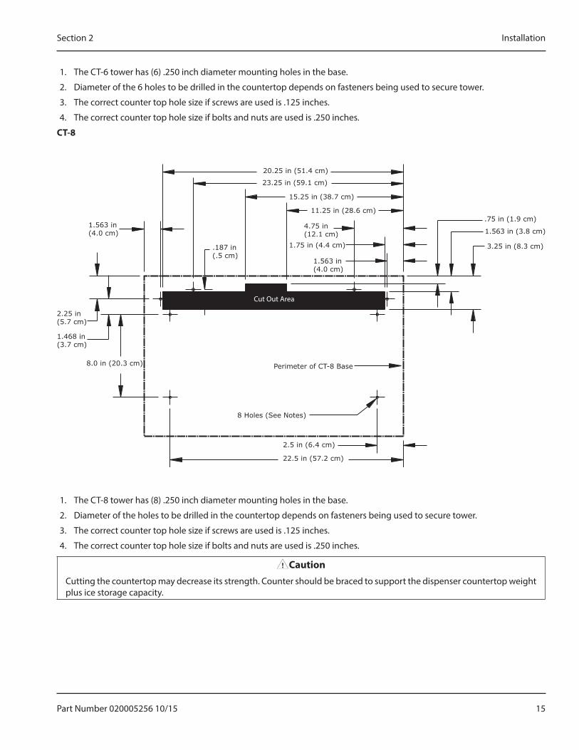
CT-8
23.25 in (59.1 cm)
15.25 in (38.7 cm)
11.25 in (28.6 cm)
4.75 in (12.1 cm)
.75 in (1.9 cm)
3.25 in (8.3 cm)1.75 in (4.4 cm)
1.563 in (4.0 cm)
1.563 in (3.8 cm)1.563 in (4.0 cm)
1.468 in (3.7 cm)
8.0 in (20.3 cm)
2.25 in (5.7 cm)
2.5 in (6.4 cm)
22.5 in (57.2 cm)
.187 in (.5 cm)
20.25 in (51.4 cm)
Perimeter of CT-8 Base
8 Holes (See Notes)
Cut Out Area
1. The CT-8 tower has (8) .250 inch diameter mounting holes in the base.
2. Diameter of the holes to be drilled in the countertop depends on fasteners being used to secure tower.
3. The correct counter top hole size if screws are used is .125 inches.
4. The correct counter top hole size if bolts and nuts are used is .250 inches.
,CautipnCutting the countertop may decrease its strength. Counter should be braced to support the dispenser countertop weight plus ice storage capacity.
16 Part Number 020005256 10/15
Installation Section 2
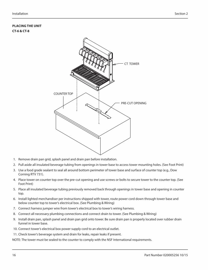
PLAC�NG THE UN�TCT-6 & CT-8
CT TOWER
PRE-CUT OPENING
COUNTER TOP
1. Remove drain pan grid, splash panel and drain pan before installation.
2. Pull aside all insulated beverage tubing from openings in tower base to access tower mounting holes. (See Foot Print)
3. Use a food grade sealant to seal all around bottom perimeter of tower base and surface of counter top (e.g., Dow Corning RTV 731).
4. Place tower on counter top over the pre-cut opening and use screws or bolts to secure tower to the counter top. (See Foot Print)
5. Place all insulated beverage tubing previously removed back through openings in tower base and opening in counter top.
6. Install lighted merchandiser per instructions shipped with tower, route power cord down through tower base and below counter top to tower’s electrical box. (See Plumbing & Wiring)
7. Connect harness jumper wire from tower’s electrical box to tower’s wiring harness.
8. Connect all necessary plumbing connections and connect drain to tower. (See Plumbing & Wiring)
9. Install drain pan, splash panel and drain pan grid onto tower. Be sure drain pan is properly located over rubber drain funnel in tower base.
10. Connect tower’s electrical box power supply cord to an electrical outlet.
11. Check tower’s beverage system and drain for leaks, repair leaks if present.
NOTE: The tower must be sealed to the counter to comply with the NSF International requirements.
Part Number 020005256 10/15 17
Section 2 Installation
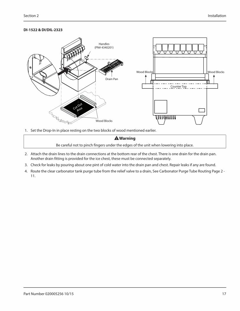
D�-1522 & D�/D�L-2323
Wood Blocks Wood Blocks
Counter Top
Handles (PN# 4340201)
Drain Pan
Wood Blocks
Cut Out
Area
1. Set the Drop-In in place resting on the two blocks of wood mentioned earlier.
nWarningBe careful not to pinch fingers under the edges of the unit when lowering into place.
2. Attach the drain lines to the drain connections at the bottom rear of the chest. There is one drain for the drain pan. Another drain fitting is provided for the ice chest, these must be connected separately.
3. Check for leaks by pouring about one pint of cold water into the drain pan and chest. Repair leaks if any are found.
4. Route the clear carbonator tank purge tube from the relief valve to a drain, See Carbonator Purge Tube Routing Page 2 - 11.
18 Part Number 020005256 10/15
Installation Section 2
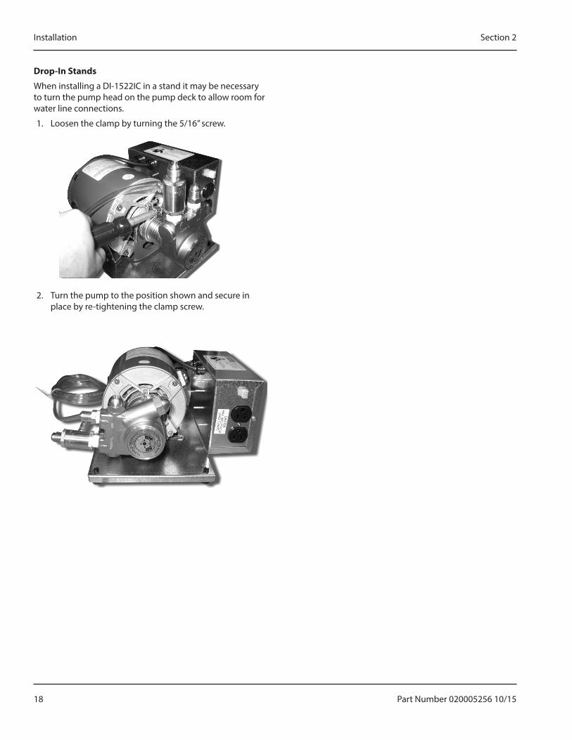
Drpm-�n Stands
When installing a DI-1522IC in a stand it may be necessary to turn the pump head on the pump deck to allow room for water line connections.
1. Loosen the clamp by turning the 5/16” screw.
2. Turn the pump to the position shown and secure in place by re-tightening the clamp screw.
Part Number 020005256 10/15 19
Section 2 Installation
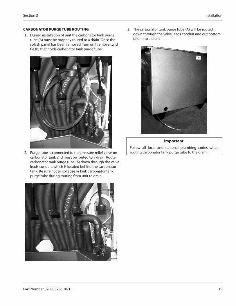
CARBONATOR PURGE TUBE ROUT�NG1. During installation of unit the carbonator tank purge
tube (A) must be properly routed to a drain. Once the splash panel has been removed from unit remove twist tie (B) that holds carbonator tank purge tube
2. Purge tube is connected to the pressure relief valve on carbonator tank and must be routed to a drain. Route carbonator tank purge tube (A) down through the valve leads conduit, which is located behind the carbonator tank. Be sure not to collapse or kink carbonator tank purge tube during routing from unit to drain.
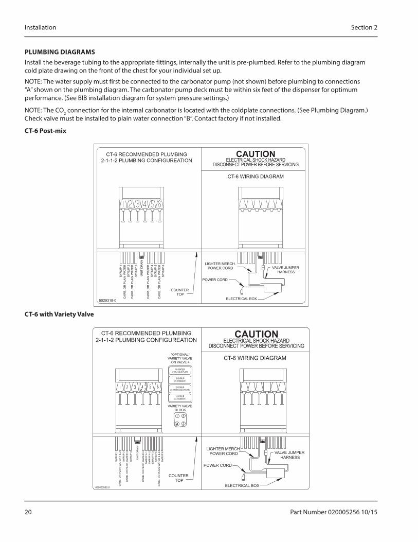
3. The carbonator tank purge tube (A) will be routed down through the valve leads conduit and out bottom of unit to a drain.
�mmprtant�Follow all local and national plumbing codes when routing carbonator tank purge tube to the drain.
20 Part Number 020005256 10/15
Installation Section 2
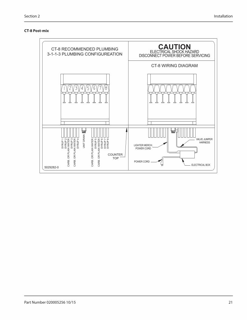
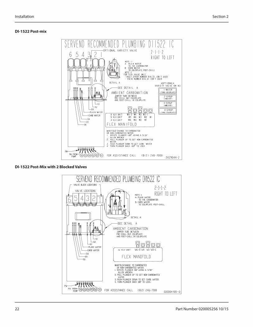
PLUMB�NG D�AGRAMSInstall the beverage tubing to the appropriate fittings, internally the unit is pre-plumbed. Refer to the plumbing diagram cold plate drawing on the front of the chest for your individual set up.
NOTE: The water supply must first be connected to the carbonator pump (not shown) before plumbing to connections “A” shown on the plumbing diagram. The carbonator pump deck must be within six feet of the dispenser for optimum performance. (See BIB installation diagram for system pressure settings.)
NOTE: The CO2 connection for the internal carbonator is located with the coldplate connections. (See Plumbing Diagram.) Check valve must be installed to plain water connection “B”. Contact factory if not installed.
CT-6 Ppst-mix
CT-6 RECOMMENDED PLUMBING2-1-1-2 PLUMBING CONFIGUREATION
CT-6 WIRING DIAGRAM
COUNTER TOP
5029318-0
SY
RU
P 1
SY
RU
P 2
SY
RU
P 3
SY
RU
P 4
SY
RU
P 5
SY
RU
P 6
UN
IT D
RA
IN
CA
RB
. OR
PLA
IN W
ATE
R
CA
RB
. OR
PLA
IN W
ATE
R
CA
RB
. OR
PLA
IN W
ATE
R
CA
RB
. OR
PLA
IN W
ATE
R LIGHTER MERCH.POWER CORD
POWER CORD
ELECTRICAL BOX
VALVE JUMPER HARNESS
CAUTIONELECTRICAL SHOCK HAZARD
DISCONNECT POWER BEFORE SERVICING
CT-6 with Variety Valve
CT-6 RECOMMENDED PLUMBING2-1-1-2 PLUMBING CONFIGUREATION
CT-6 WIRING DIAGRAM
COUNTER TOP
VARIETY VALVE BLOCK
W-WATER(THRU COLD PLATE)
3-SYRUP(#4-3 AMBIENT)
2-SYRUP(#4-2 THRU COLD PLATE)
1-SYRUP(#4-2 AMBIENT)
*OPTIONAL*VARIETY VALVE
ON VALVE 4
020003552-0
SY
RU
P 1
SY
RU
P 2
SY
RU
P 3
SY
RU
P 4-
1S
YR
UP
4-2
SY
RU
P 4-
3S
YR
UP
5
SY
RU
P 6
UN
IT D
RA
IN
CA
RB
. OR
PLA
IN W
ATE
R 1
& 2
CA
RB
. OR
PLA
IN W
ATE
R 3
CA
RB
. OR
PLA
IN W
ATE
R 4
CA
RB
. OR
PLA
IN W
ATE
R 5
& 6
LIGHTER MERCH.POWER CORD
POWER CORD
ELECTRICAL BOX
VALVE JUMPER HARNESS
CAUTIONELECTRICAL SHOCK HAZARD
DISCONNECT POWER BEFORE SERVICING
Part Number 020005256 10/15 21
Section 2 Installation
CT-8 Ppst-mix
CT-8 RECOMMENDED PLUMBING3-1-1-3 PLUMBING CONFIGUREATION
CT-8 WIRING DIAGRAM
COUNTER TOP
5029282-0
SY
RU
P 1
SY
RU
P 2
SY
RU
P 3
SY
RU
P 4
SY
RU
P 5
SY
RU
P 6
SY
RU
P 7
SY
RU
P 8
UN
IT D
RA
IN
CA
RB
. OR
PLA
IN W
ATE
R
CA
RB
. OR
PLA
IN W
ATE
R
CA
RB
. OR
PLA
IN W
ATE
R
CA
RB
. OR
PLA
IN W
ATE
R
LIGHTER MERCH.POWER CORD
POWER CORDELECTRICAL BOX
VALVE JUMPER HARNESS
CAUTIONELECTRICAL SHOCK HAZARD
DISCONNECT POWER BEFORE SERVICING
22 Part Number 020005256 10/15
Installation Section 2
D�-1522 Ppst-mix
D�-1522 Ppst-Mix with 2 Blpcked Valves
Part Number 020005256 10/15 23
Section 2 Installation
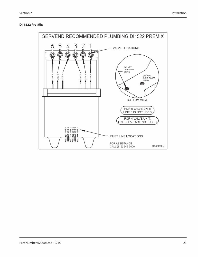
D�-1522 Pre-Mix
SERVEND RECOMMENDED PLUMBING DI1522 PREMIX
VALVE LOCATIONS
BOTTOM VIEW
INLET LINE LOCATIONS
FOR 5 VALVE UNIT:LINE 6 IS NOT USED
3/4” NPTDRAIN PANDRAIN
3/4” NPTCOLD PLATEDRAIN
FOR ASSISTANCECALL (812) 246-7000 5009449-0
LIN
E 6
LIN
E 5
LIN
E 4
LIN
E 6
LIN
E 5
LIN
E 4
LIN
E 3
LIN
E 2
LIN
E 1
LIN
E 3
LIN
E 2
LIN
E 1
FOR 4 VALVE UNIT:LINES 1 & 6 ARE NOT USED
24 Part Number 020005256 10/15
Installation Section 2
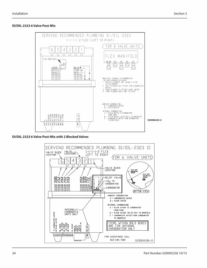
D�/D�L-2323 6 Valve Ppst-Mix
020006242-2
D�/D�L-2323 6 Valve Ppst-Mix with 2 Blpcked Valves
Part Number 020005256 10/15 25
Section 2 Installation
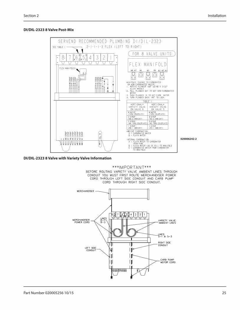
D�/D�L-2323 8 Valve Ppst-Mix
020006242-2
D�/D�L-2323 8 Valve with Variety Valve �nfprmatipn
26 Part Number 020005256 10/15
Installation Section 2
D�/D�L-2323 10 Valve Ppst-Mix
020006242-2
D�/D�L-2323 6 Valve Pre-Mix
SERVEND RECOMMENDED PLUMBING DI/DIL-2323
VALVE LOCATIONS
BOTTOM VIEW
INLET LINE LOCATIONS
FOR 5 VALVE UNIT:INLET 6 IS NOT USEDVALVE 6 IS NOT USED
3/4” NPTDRAIN PANDRAIN
3/4” NPTCOLD PLATEDRAIN
FOR ASSISTANCECALL (812) 246-7000 5009394-0
SY
RU
P 1
SY
RU
P 2
SY
RU
P 3
SY
RU
P 1
SY
RU
P 2
SY
RU
P 3
SY
RU
P 4
SY
RU
P 5
SY
RU
P 6
SY
RU
P 4
SY
RU
P 5
SY
RU
P 6
Part Number 020005256 10/15 27
Section 2 Installation
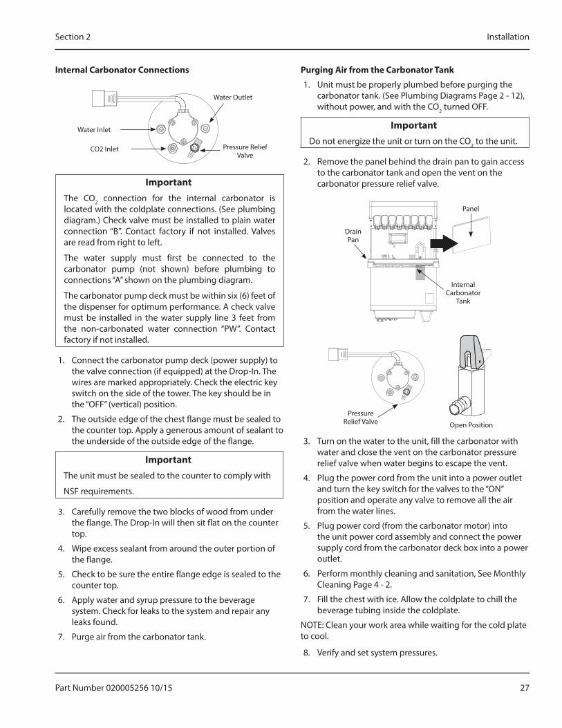
�nternal Carbpnatpr Cpnnectipns
Water Outlet
Water Inlet
CO2 Inlet Pressure Relief Valve
�mmprtant�The CO2 connection for the internal carbonator is located with the coldplate connections. (See plumbing diagram.) Check valve must be installed to plain water connection “B”. Contact factory if not installed. Valves are read from right to left.
The water supply must first be connected to the carbonator pump (not shown) before plumbing to connections “A” shown on the plumbing diagram.
The carbonator pump deck must be within six (6) feet of the dispenser for optimum performance. A check valve must be installed in the water supply line 3 feet from the non-carbonated water connection “PW”. Contact factory if not installed.
1. Connect the carbonator pump deck (power supply) to the valve connection (if equipped) at the Drop-In. The wires are marked appropriately. Check the electric key switch on the side of the tower. The key should be in the “OFF” (vertical) position.
2. The outside edge of the chest flange must be sealed to the counter top. Apply a generous amount of sealant to the underside of the outside edge of the flange.
�mmprtant�The unit must be sealed to the counter to comply with
NSF requirements.
3. Carefully remove the two blocks of wood from under the flange. The Drop-In will then sit flat on the counter top.
4. Wipe excess sealant from around the outer portion of the flange.
5. Check to be sure the entire flange edge is sealed to the counter top.
6. Apply water and syrup pressure to the beverage system. Check for leaks to the system and repair any leaks found.
7. Purge air from the carbonator tank.
Purging Air frpm the Carbpnatpr Tank
1. Unit must be properly plumbed before purging the carbonator tank. (See Plumbing Diagrams Page 2 - 12), without power, and with the CO2 turned OFF.
�mmprtant�Do not energize the unit or turn on the CO2 to the unit.
2. Remove the panel behind the drain pan to gain access to the carbonator tank and open the vent on the carbonator pressure relief valve.
Panel
Drain Pan
Internal Carbonator
Tank
Pressure Relief Valve Open Position
3. Turn on the water to the unit, fill the carbonator with water and close the vent on the carbonator pressure relief valve when water begins to escape the vent.
4. Plug the power cord from the unit into a power outlet and turn the key switch for the valves to the “ON” position and operate any valve to remove all the air from the water lines.
5. Plug power cord (from the carbonator motor) into the unit power cord assembly and connect the power supply cord from the carbonator deck box into a power outlet.
6. Perform monthly cleaning and sanitation, See Monthly Cleaning Page 4 - 2.
7. Fill the chest with ice. Allow the coldplate to chill the beverage tubing inside the coldplate.
NOTE: Clean your work area while waiting for the cold plate to cool.
8. Verify and set system pressures.
28 Part Number 020005256 10/15
Installation Section 2
Pressure Settings
1. Incoming tap water should be at a minimum static pressure of 40 psi (2.758 bars) and a maximum of 55 psi (3.792 bars) with carbonator pump operating (measured at inlet to pump).
2. BIB pressure gauge set for 60 psi (4.137 bars) or according to your line run.
3. Carbonator Pressure Gauge (Use Preset Regulator):
• Cold Carbonation set for 75 psi (5.171 bars). NOTE: If incoming dynamic water pressure is under 40 psi (2.758 bars), a water booster is recommended. If incoming static water pressure is over 55 psi (3.792 bars), a water regulating valve is required.
Pre-mix Pressures
Normal pre-mix pressure regulators should be set at 60 PSI. Diet pre-mix pressure regulators should be set at 40 PSI. If you are experiencing high foaming, decreasing the pressures may correct the problem. Spitting and popping usually requires slightly increasing the pressures. Pre-mix beverage valve pressures vary by type and manufacturer. Please consult the manufacturer of the valves you are using for specific instructions regarding operation of the valve.
Bag-in-Bpx (B�B) Start-um
All lines should be properly flushed and sanitized before starting the unit. See Bag-In-Box System Sanitation page 39.
1. Connect each BIB connector to the appropriate BIB.
2. Gradually adjust the secondary regulator to 70 psi. Never run a BIB pump without the BIB installed as the pump could be damaged. Set final secondary regulator pressure 70 -75 psi depending on the line size and the distance of the run.
3. Push each valve operator one at a time. Operate each valve long enough to obtain both syrup and water through the valve.
4. See Back Room Package page 34 for more details on all BIB components.
�nstall Labels
Install flavor labels on the dispensing valve covers.
Clean Um
1. Wipe down the Drop-In and make final inspection of the area.
2. Clean up all work areas. Dispose of all packing material, excess tubing and trash properly.
Part Number 020005256 10/15 29
Section 2 Installation
START�NG SYSTEM & D�SPENSERUpon completion of the beverage dispenser and / or system installation, all tubing, dispenser, and system components must be cleaned and sanitized prior to use.
NOTE: At installation equipment, dispensers, and tubing get moved through many environments, dirt, dust, chases, insulation, drywall, etc. It is an important procedure and best practice to address cleaning to deliver the best quality drink to your customer.
Clean and sanitize the water and syrup circuits according to instructions provided in this manual. Clean and sanitize the dispenser components according to instructions provided in this manual. Consult and use local health codes if a discrepancy occurs between this manual and your local health codes.
nWarningCarbon Dioxide (CO2) displaces oxygen. Exposure to a high concentration of CO2 gas causes tremors, which are followed rapidly by loss of consciousness and suffocation. If a CO2 gas leak is suspected, particularly in a small area, immediately ventilate the area before repairing the leak. CO2 lines and pumps should not be installed in an enclosed space. An enclosed space can be a cooler or small room or closet. This may include convenience stores with glass door self serve coolers. If you suspect CO2 may build up in an area, venting of the B-I-B pumps and / or CO2 monitors should be utilized.
Test Draw Temmerature
Draw temperature test is only to be done after the coldplate has completely chilled.
1. Operate one valve for about 15 seconds.
2. Take a temperature reading of the beverage on the next 15 second draw. If the sample drawn is 40°F or lower, go to the next step. If the beverage is higher than 40°F, wait 10 minutes longer for the beverage to attain the proper temperatures. Then repeat this step.
3. When the beverage achieves the proper temperature the valves syrup to water ratio (brix) can be set.
4. Install flavor labels on the dispensing valve covers then proceed to brix the valves.
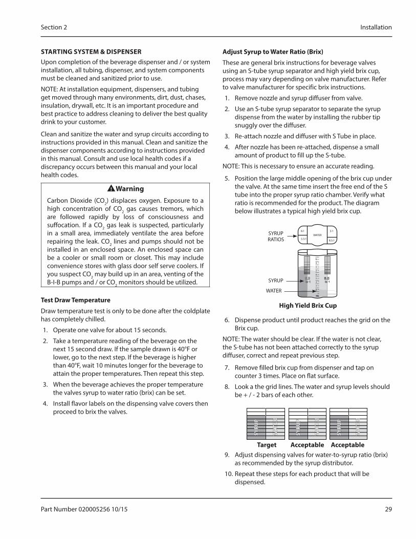
Adjust Syrum tp Water Ratip (Brix)
These are general brix instructions for beverage valves using an S-tube syrup separator and high yield brix cup, process may vary depending on valve manufacturer. Refer to valve manufacturer for specific brix instructions.
1. Remove nozzle and syrup diffuser from valve.
2. Use an S-tube syrup separator to separate the syrup dispense from the water by installing the rubber tip snuggly over the diffuser.
3. Re-attach nozzle and diffuser with S Tube in place.
4. After nozzle has been re-attached, dispense a small amount of product to fill up the S-tube.
NOTE: This is necessary to ensure an accurate reading.
5. Position the large middle opening of the brix cup under the valve. At the same time insert the free end of the S tube into the proper syrup ratio chamber. Verify what ratio is recommended for the product. The diagram below illustrates a typical high yield brix cup.
6:1
5.5:1 8.5:1
5:1WATER
5.5 to 1
8.5 to 1
9
10
8
7
6
5
4
3
2
OZ.
SYRUP RATIOS
SYRUP
WATER
High Yield Brix Cum
6. Dispense product until product reaches the grid on the Brix cup.
NOTE: The water should be clear. If the water is not clear, the S-tube has not been attached correctly to the syrup diffuser, correct and repeat previous step.
7. Remove filled brix cup from dispenser and tap on counter 3 times. Place on flat surface.
8. Look a the grid lines. The water and syrup levels should be + / - 2 bars of each other.
SYRU
P
WAT
ER
SYRU
P
WAT
ER
SYRU
P
WAT
ER
Target Accemtable Accemtable9. Adjust dispensing valves for water-to-syrup ratio (brix)
as recommended by the syrup distributor.
10. Repeat these steps for each product that will be dispensed.
30 Part Number 020005256 10/15
Installation Section 2
THIS PAGE INTENTIONALLY LEFT BLANK
Part Number 020005256 10/15 31
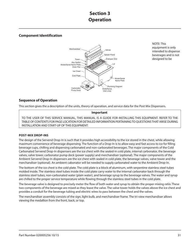
Component Identification
Valves
Splash Panel
Drainpan Grid
Lid
Model/Serial Name Plate
Plumbing DiagramSoda/Syrup Inlet Lines
Carbonator Pump Deck
Cold Plate
Ice Chest
Drain Pan
Key Switch
Tower
Merchandiser
Model/Serial Name Plate
Sequence of OperationThis section gives the a description of the units, theory of operation, and service data for the Post Mix Dispensers.
Important�TO THE USER OF THIS SERVICE MANUAL, THIS MANUAL IS A GUIDE FOR INSTALLING THIS EQUIPMENT. REFER TO THE TABLE OF CONTENTS FOR PAGE LOCATION FOR DETAILED INFORMATION PERTAINING TO QUESTIONS THAT ARISE DURING INSTALLATION AND START-UP OF THIS EQUIPMENT.
POST-MIX DROP-INSThe design of the Servend Drop-In is such that it provides high accessibility to the ice stored in the chest, while allowing maximum convenience of beverage dispensing. The function of a Drop-In is to allow easy and fast access to ice for filling beverage cups, chilling and dispensing carbonated and non-carbonated beverages. The major components of the Cold Carbonated Servend Drop-In dispensers are the ice chest with the sealed-in cold plate, internal carbonator, the beverage valves, valve tower, carbonator pump deck (power supply) and merchandiser (optional). The major components of the Ambient Servend Drop-In dispensers are the ice chest with sealed in cold plate, the beverage valves, valve tower and the merchandiser (optional). An ambient cabonator will be needed to supply carbonated water to the Ambient Drop-In.
The bottom of the ice chest is the cold plate. The cold plate is a block of aluminum, with serpentine stainless steel tubes molded inside. The stainless steel tubes inside the cold plate carry water to the internal carbonator back through the stainless steel tubes, non-carbonated water (plain water), and beverage syrup to the beverage valves. The water and syrup are chilled to the proper service temperature while flowing through the stainless steel tubes in the cold plate.
The beverage valve is designed to precisely meter the flow of both water and syrup to obtain the proper mixing ratio. These two components of the beverage are mixed as they leave the valve. The valve tower holds the valves above the ice chest and provides a conduit for the beverage tubing and electric wires to pass between the chest and the valves.
The merchandiser assembly consists of the sign, light bulb, and merchandiser frame. The tri-view merchandiser allows viewing the medallion from the front, back, or top.
Section 3Operation
NOTE: This equipment is only intended to dispense beverages and is not designed to be
32 Part Number 020005256 10/15
Operation Section 3
PRE-MIX DROP-INSPre-mix fountain dispensing consists of a container of beverage ready for dispensing, beverage delivery system, carbon dioxide (CO2) propellant, beverage cooling system, and dispenser. We shall discuss each component of this type of system within the context of this manual.
The major advantage of a pre-mix system over most other types is its flexibility. This flexibility is the ability to go anywhere. Many pre-mix systems will operate without electric power or separate water supply. Most drop-ins are manufactured for post-mix. Unless otherwise stated, operation and installation instructions are for post-mix.
STANDS
Stands are designed to accommodate drop-in ice bins and to provide an enclosure for carbonators. See instructions provided with those items for proper installation and connections.
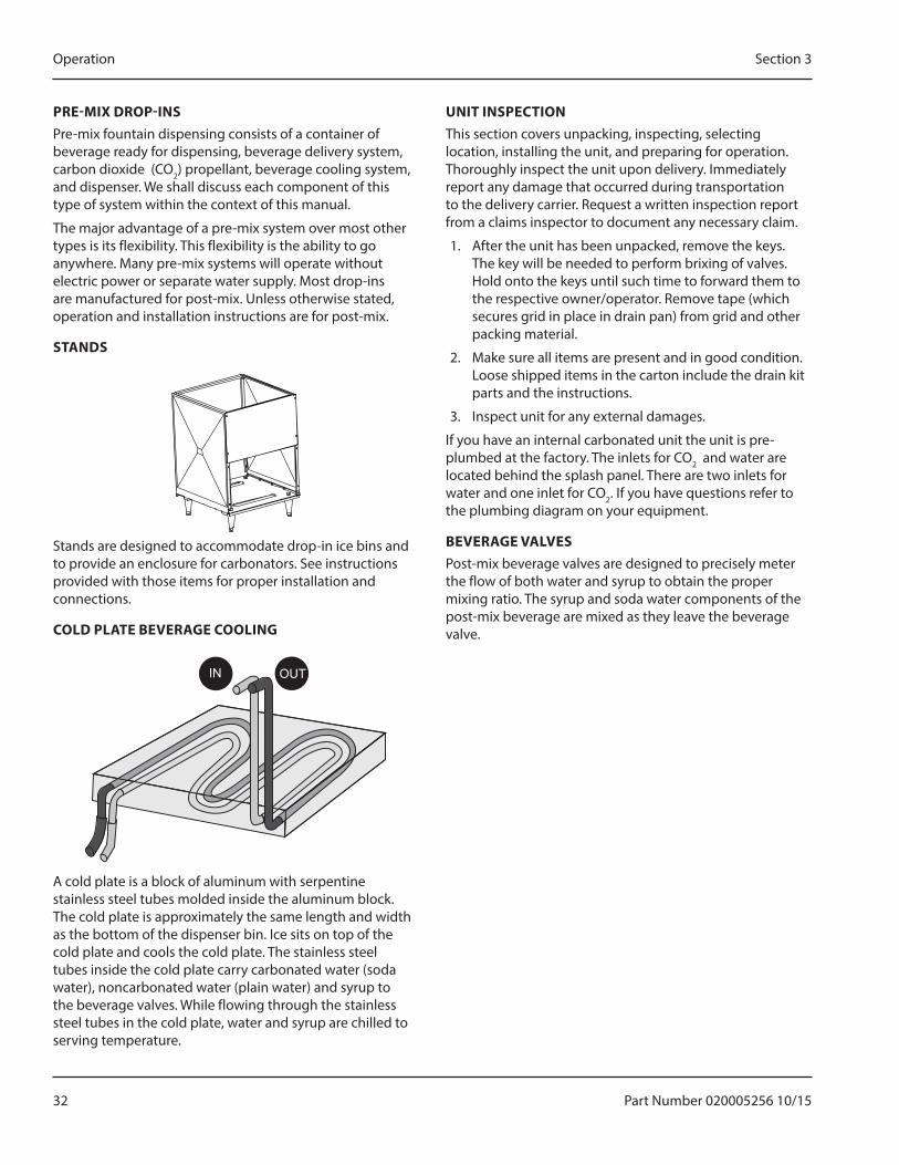
COLD PLATE BEVERAGE COOLING
IN OUT
A cold plate is a block of aluminum with serpentine stainless steel tubes molded inside the aluminum block. The cold plate is approximately the same length and width as the bottom of the dispenser bin. Ice sits on top of the cold plate and cools the cold plate. The stainless steel tubes inside the cold plate carry carbonated water (soda water), noncarbonated water (plain water) and syrup to the beverage valves. While flowing through the stainless steel tubes in the cold plate, water and syrup are chilled to serving temperature.
UNIT INSPECTIONThis section covers unpacking, inspecting, selecting location, installing the unit, and preparing for operation. Thoroughly inspect the unit upon delivery. Immediately report any damage that occurred during transportation to the delivery carrier. Request a written inspection report from a claims inspector to document any necessary claim.
1. After the unit has been unpacked, remove the keys. The key will be needed to perform brixing of valves. Hold onto the keys until such time to forward them to the respective owner/operator. Remove tape (which secures grid in place in drain pan) from grid and other packing material.
2. Make sure all items are present and in good condition. Loose shipped items in the carton include the drain kit parts and the instructions.
3. Inspect unit for any external damages.
If you have an internal carbonated unit the unit is pre-plumbed at the factory. The inlets for CO2 and water are located behind the splash panel. There are two inlets for water and one inlet for CO2. If you have questions refer to the plumbing diagram on your equipment.
BEVERAGE VALVESPost-mix beverage valves are designed to precisely meter the flow of both water and syrup to obtain the proper mixing ratio. The syrup and soda water components of the post-mix beverage are mixed as they leave the beverage valve.
Part Number 020005256 10/15 33
Section 3 Operation
CO2 SUPPLYNOTE: CO2 inlet for the internal carbonator is located with the cold plate inlet lines.
(See plumbing diagram for exact plumbing location)
• CO2 pressure to the BIB pump is 60 to 75 psi.
• DI-1522, 2323 & DIL-2323 CO2 pressure to the internal carbonator is 75 psi.
• For ambient carbonated systems the CO2 pressure to the carbonator should be set at 100 PSI
• “Optional” A low CO2 alarm is available on all internally Carbonated DI series units. A RED low CO2 light mounted to the tower will illuminate when the CO2 supply for the cabonator tank starts running low.
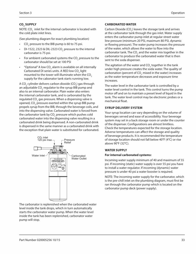
A CO2 cylinder delivers carbon dioxide (CO2) gas through an adjustable CO2 regulator to the syrup BIB pump and also to an internal carbonator. Plain water also enters the internal carbonator tank, and is carbonated by the regulated CO2 gas pressure. When a dispensing valve is opened, CO2 pressure exerted within the syrup BIB pump propels syrup from the BIB, through the beverage coils, and into the dispensing valve. Carbonated water is forced from the carbonator tank by CO2 pressure which pushes cold carbonated water into the dispensing valve resulting in a carbonated drink being dispensed. A non-carbonated drink is dispensed in the same manner as a carbonated drink with the exception that plain water is substituted for carbonated.
Carbonated Water Outlet
PressureRelief
CO2 inlet 120 psi max
Water Inlet
The carbonator is replenished when the carbonated water level inside the tank drops, which in turn automatically starts the carbonator water pump. When the water level inside the tank has been replenished, carbonator water pump will stop.
CARBONATED WATERCarbon Dioxide (CO2) leaves the storage tank and arrives at the carbonator tank through the gas inlet. Water supply enters the carbonator pump inlet at regular street water line pressure (minimum 20 PSI, maximum 80 PSI, dynamic or flowing pressure). The water pump increases the pressure of the water, which allows the water to flow into the carbonator tank. The CO2 and the water mix together in the carbonator to produce the carbonated water that is then sent to the soda dispenser.
The agitation of the water and CO2 together in the tank under high pressure creates the soda water. The quality of carbonation (percent of CO2 mixed in the water) increases as the water temperature decreases and exposure time increases.
The water level in the carbonator tank is controlled by a water level control in the tank. This control turns the pump motor off and on to maintain a preset level of liquid in the tank. The water level control may be electronic probes or a mechanical float.
SYRUP DELIVERY SYSTEMYour syrup location can vary depending on the volume of beverages served and ease of accessibility. Your beverage system may set in a back storage room or under the counter of the dispenser. Configurations are almost limitless. Check the temperatures expected for the storage location. Adverse temperatures can affect the storage and quality of beverage products. It is recommended the temperature of storage location should not fall below 40°F (4°C) or rise above 90°F (32°C).
WATER SUPPLYFor internal carbonated systems:
Incoming water supply minimum of 40 and maximum of 55 psi. If incoming (static) water supply is over 55 psi you have to install a water regulator. If incoming (dynamic) water pressure is under 40 psi a water booster is required.
NOTE: The incoming water supply for the carbonator, which is the pre-chill inlet on the plumbing diagram, must first be ran through the carbonator pump which is located on the carbonator pump deck (power supply).

34 Part Number 020005256 10/15
Operation Section 3
BACK ROOM PACKAGE
Booster System (If Required)
Water Regulator 40–55 PSI
Filter
To CO2 Manifold (BIB Pumps) from CO2 Supply
60 PSI
To Syrup Inlet Barbs on Unit
To BIB Pumps from BIB
To Non-carbonated Water Inlet Barb
Water to Carbonator
Pump
To BIB Pump
BIB
From Water Supply
1. Incoming tap water - should be at a minimum dynamic pressure of 40 psi and maximum static pressure of 55 psi.
2. Carbonator Water pump motor - Powers the water pump. The water pump motor is part of the carbonator pump deck.
3. Carbonator Water pump - Pumps tap water into the carbonator tank. The water pump is part of the carbonator. The incoming water for the carbonator must be first run through the pump before connecting to the proper cold plate inlet.
4. Internal/External Carbonator tank - Combines CO2 gas and tap water to form carbonated water. The “carbonator” is the carbonator tank, water pump and water pump motor.
5. CO2 cylinder - Holds highly pressurized carbon dioxide (CO2). The CO2 cylinder is a steel or aluminum cylinder tank. CO2 gas flows through the primary pressure regulator.
6. BIB pressure gauge - Set for a minimum of 60 psi. Indicates CO2 pressure going to B-I-B pumps.
7. Primary pressure regulator - Lowers the CO2 gas pressure, to 100 psi, so the CO2 gas will be at the proper pressure to enter the carbonator regulator.
8. Lowered outgoing pressure - Set for 75 psi. Gauge indicates lowered outgoing pressure from the CO2 cylinder after being routed through the primary pressure regulator at 100 psi.
9. Secondary pressure regulator - Lowers the CO2 gas pressure before the CO2 gas flows to the syrup pump. CO2 pressure activates the syrup pump.
10. Syrup pump - Draws syrup out of the bag-in-box syrup package. Syrup flows through the syrup lines to the dispenser for chilling, then dispensing. There is a syrup pump for each bag-in-box syrup system.
11. Bag-In-Box syrup cartons - Box which contains a plastic bag, filled with syrup.
FIGAL SYSTEMFigal refers to the stainless steel tanks of pre-mix beverage or post-mix syrup. The term “Figal” is an abbreviated word. Originally Figal was short for “five gallons”. Today, the term usually refers to any stainless steel tank system used in soft drink beverage supply. The CO2 to push the beverage from the Figal tank is sourced from a small CO2 tank.
3/8 Syrup Lines to Dispenser
Soda Water
Carbonated Water to Dispenser
Incoming Water
Pump Carbonator
CO2
100 psi
Part Number 020005256 10/15 35
Section 3 Operation
FIGAL TANKSThe stainless steel Figal beverage tanks are easy to store and connect. There are several items to remember when using the Figal tanks:
• Use a gas connector for the inlet fitting of the tank.
• Use a syrup connector for the outlet fitting of the tank.
• If more than one Figal tank is connected in series, when changing tanks, remove the tank closest to the original gas inlet while adding the new tank to the connector closest to the syrup outlet.
Most Figal tanks have a self-closing valve on the tank as well as the gas and syrup connectors. This allows the operator of the system to change tanks without having to shut down the entire system. With this type of connector, push down on the connector while pulling up on the snap ring around the opening of the connector. Then simply pull the connector off the tank.
RACKINGRegardless if you are working on a B-I-B or Figal system, a place will be designated for placement of the product. A rack (or shelf ) system affords systematic placement and complete usage of the beverage paid for. The B-I-B rack allows the boxes to lay properly for syrup dispersal. Please check with your B-I-B syrup supplier. Some boxes must be slightly tilted down, while others may be in virtually any position. The Figal tank rack keeps the newer and full tanks organized at one end of the beverage line with the partial tanks at the other.
B-I-BThe Bag-In-Box system refers to a plastic disposable bag. The B-I-B normally contains 5 gallons of syrup, however some locations offer 2-1/2 gallon B-I-B units. This plastic bag is then held inside a cardboard or other container. B-I-B systems are for post-mix applications only.
PUMPSThe syrup in a B-I-B system is delivered to the beverage system through gas operated pumps. These pumps extract the syrup out of the bags, forcing the syrup throughout the system.
AUTO BAG SELECTORSThese are used on higher volume B-I-B systems where two or more bags of the same product are connected to one pump and one system. An auto bag selector is essentially a valve that automatically changes from one bag (or series of bags) to another bag (or series of bags) of syrup as the bags empty, allowing a constant flow of product.
36 Part Number 020005256 10/15
Operation Section 3
THIS PAGE INTENTIONALLY LEFT BLANK
Part Number 020005256 10/15 37
Cleaning
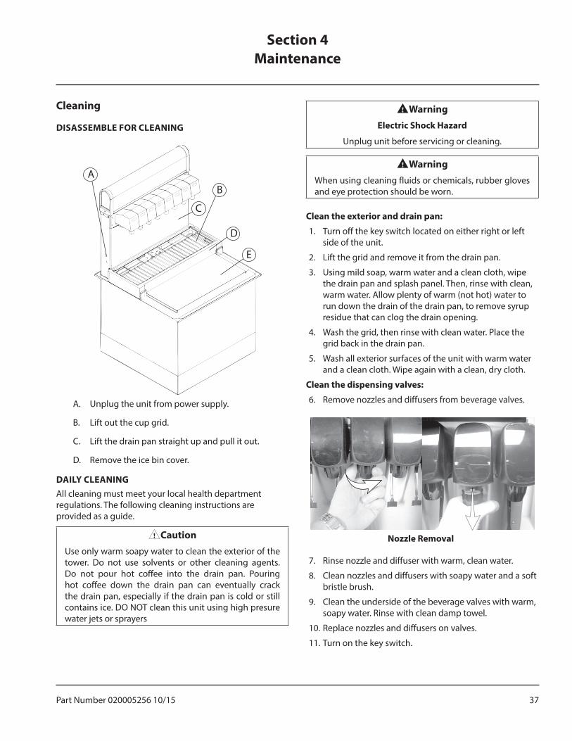
DISASSEMBLE FOR CLEANING
A
C
B
D
E
A. Unplug the unit from power supply.
B. Lift out the cup grid.
C. Lift the drain pan straight up and pull it out.
D. Remove the ice bin cover.
DAILY CLEANINGAll cleaning must meet your local health department regulations. The following cleaning instructions are provided as a guide.
,CautionUse only warm soapy water to clean the exterior of the tower. Do not use solvents or other cleaning agents. Do not pour hot coffee into the drain pan. Pouring hot coffee down the drain pan can eventually crack the drain pan, especially if the drain pan is cold or still contains ice. DO NOT clean this unit using high presure water jets or sprayers
nWarningElectric Shock Hazard
Unplug unit before servicing or cleaning.
nWarningWhen using cleaning fluids or chemicals, rubber gloves and eye protection should be worn.
Clean the exterior and drain pan:
1. Turn off the key switch located on either right or left side of the unit.
2. Lift the grid and remove it from the drain pan.
3. Using mild soap, warm water and a clean cloth, wipe the drain pan and splash panel. Then, rinse with clean, warm water. Allow plenty of warm (not hot) water to run down the drain of the drain pan, to remove syrup residue that can clog the drain opening.
4. Wash the grid, then rinse with clean water. Place the grid back in the drain pan.
5. Wash all exterior surfaces of the unit with warm water and a clean cloth. Wipe again with a clean, dry cloth.
Clean the dispensing valves:
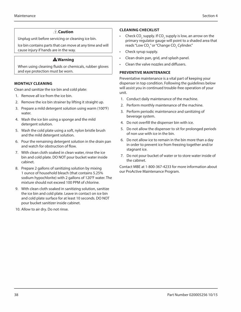
6. Remove nozzles and diffusers from beverage valves.
Nozzle Removal
7. Rinse nozzle and diffuser with warm, clean water.
8. Clean nozzles and diffusers with soapy water and a soft bristle brush.
9. Clean the underside of the beverage valves with warm, soapy water. Rinse with clean damp towel.
10. Replace nozzles and diffusers on valves.
11. Turn on the key switch.
Section 4Maintenance
38 Part Number 020005256 10/15
Maintenance Section 4
,CautionUnplug unit before servicing or cleaning ice bin.
Ice bin contains parts that can move at any time and will cause injury if hands are in the way.
nWarningWhen using cleaning fluids or chemicals, rubber gloves and eye protection must be worn.
MONTHLY CLEANINGClean and sanitize the ice bin and cold plate:
1. Remove all ice from the ice bin.
2. Remove the ice bin strainer by lifting it straight up.
3. Prepare a mild detergent solution using warm (100°F) water.
4. Wash the ice bin using a sponge and the mild detergent solution.
5. Wash the cold plate using a soft, nylon bristle brush and the mild detergent solution.
6. Pour the remaining detergent solution in the drain pan and watch for obstruction of flow.
7. With clean cloth soaked in clean water, rinse the ice bin and cold plate. DO NOT pour bucket water inside cabinet.
8. Prepare 2 gallons of sanitizing solution by mixing 1 ounce of household bleach (that contains 5.25% sodium hypochlorite) with 2 gallons of 120°F water. The mixture should not exceed 100 PPM of chlorine.
9. With clean cloth soaked in sanitizing solution, sanitize the ice bin and cold plate. Leave in contact on ice bin and cold plate surface for at least 10 seconds. DO NOT pour bucket sanitizer inside cabinet.
10. Allow to air dry. Do not rinse.
CLEANING CHECKLIST• Check CO2 supply. If CO2 supply is low, an arrow on the
primary regulator gauge will point to a shaded area that reads “Low CO2” or “Change CO2 Cylinder.”
• Check syrup supply.
• Clean drain pan, grid, and splash panel.
• Clean the valve nozzles and diffusers.
PREVENTIVE MAINTENANCEPreventative maintenance is a vital part of keeping your dispenser in top condition. Following the guidelines below will assist you in continued trouble-free operation of your unit.
1. Conduct daily maintenance of the machine.
2. Perform monthly maintenance of the machine.
3. Perform periodic maintenance and sanitizing of beverage system.
4. Do not overfill the dispenser bin with ice.
5. Do not allow the dispenser to sit for prolonged periods of non use with ice in the bin.
6. Do not allow ice to remain in the bin more than a day in order to prevent ice from freezing together and/or stagnant ice.
7. Do not pour bucket of water or to store water inside of the cabinet.
Contact MBE at 1-800-367-4233 for more information about our ProActive Maintenance Program.
Part Number 020005256 10/15 39
Section 4 Maintenance
Sanitizing
BEVERAGE SYSTEM CLEANING
nWarningFlush sanitizing solution from syrup system.
Residual sanitizing solution left in system could create a health hazard.
nWarningWhen using cleaning fluids or chemicals, rubber gloves and eye protection must be worn.
Sanitize the beverage system at initial start-up as well as regularly scheduled cleaning. The drain pan must be in place under soda valves, to carry away detergent and sanitizing agents that will be flushed through valves.
BAG-IN-BOX SYSTEM SANITATIONThe procedure below is for the sanitation of one syrup circuit at a time. Repeat to sanitize additional circuits.
You will need the following items to clean and sanitize the Bag-in-Box (BIB) beverage system:
• Three (3) clean buckets• Plastic brush or soft cloth• Mild detergent• Unscented bleach (5% Na CL O) or• Commercial sanitizer• Bag-In-Box bag connector
1. Prepare the following in the buckets:
• Bucket 1 — warm to hot tap water for rinsing.• Bucket 2 — mild detergent and warm to hot
water.• Bucket 3 — mix a solution of unscented bleach
(5% Na CL O) or commercial sanitizer and warm to hot water. Mixture should supply 100 PPM available chlorine (1/4 oz. bleach to 1 gallon water).
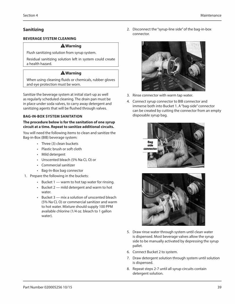
2. Disconnect the “syrup-line side” of the bag-in-box connector.
3. Rinse connector with warm tap water.
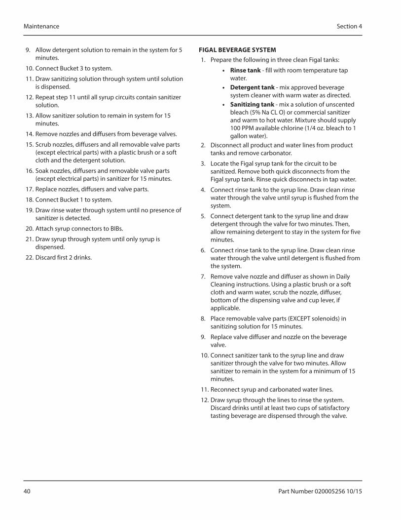
4. Connect syrup connector to BIB connector and immerse both into Bucket 1. A “bag-side” connector can be created by cutting the connector from an empty disposable syrup bag.
Bagside
connector
5. Draw rinse water through system until clean water is dispensed. Most beverage valves allow the syrup side to be manually activated by depressing the syrup pallet.
6. Connect Bucket 2 to system.
7. Draw detergent solution through system until solution is dispensed.
8. Repeat steps 2-7 until all syrup circuits contain detergent solution.
40 Part Number 020005256 10/15
Maintenance Section 4
9. Allow detergent solution to remain in the system for 5 minutes.
10. Connect Bucket 3 to system.
11. Draw sanitizing solution through system until solution is dispensed.
12. Repeat step 11 until all syrup circuits contain sanitizer solution.
13. Allow sanitizer solution to remain in system for 15 minutes.
14. Remove nozzles and diffusers from beverage valves.
15. Scrub nozzles, diffusers and all removable valve parts (except electrical parts) with a plastic brush or a soft cloth and the detergent solution.
16. Soak nozzles, diffusers and removable valve parts (except electrical parts) in sanitizer for 15 minutes.
17. Replace nozzles, diffusers and valve parts.
18. Connect Bucket 1 to system.
19. Draw rinse water through system until no presence of sanitizer is detected.
20. Attach syrup connectors to BIBs.
21. Draw syrup through system until only syrup is dispensed.
22. Discard first 2 drinks.
FIGAL BEVERAGE SYSTEM1. Prepare the following in three clean Figal tanks:
• Rinse tank - fill with room temperature tap water.
• Detergent tank - mix approved beverage system cleaner with warm water as directed.
• Sanitizing tank - mix a solution of unscented bleach (5% Na CL O) or commercial sanitizer and warm to hot water. Mixture should supply 100 PPM available chlorine (1/4 oz. bleach to 1 gallon water).
2. Disconnect all product and water lines from product tanks and remove carbonator.
3. Locate the Figal syrup tank for the circuit to be sanitized. Remove both quick disconnects from the Figal syrup tank. Rinse quick disconnects in tap water.
4. Connect rinse tank to the syrup line. Draw clean rinse water through the valve until syrup is flushed from the system.
5. Connect detergent tank to the syrup line and draw detergent through the valve for two minutes. Then, allow remaining detergent to stay in the system for five minutes.
6. Connect rinse tank to the syrup line. Draw clean rinse water through the valve until detergent is flushed from the system.
7. Remove valve nozzle and diffuser as shown in Daily Cleaning instructions. Using a plastic brush or a soft cloth and warm water, scrub the nozzle, diffuser, bottom of the dispensing valve and cup lever, if applicable.
8. Place removable valve parts (EXCEPT solenoids) in sanitizing solution for 15 minutes.
9. Replace valve diffuser and nozzle on the beverage valve.
10. Connect sanitizer tank to the syrup line and draw sanitizer through the valve for two minutes. Allow sanitizer to remain in the system for a minimum of 15 minutes.
11. Reconnect syrup and carbonated water lines.
12. Draw syrup through the lines to rinse the system. Discard drinks until at least two cups of satisfactory tasting beverage are dispensed through the valve.
Part Number 020005256 10/15 41
Section 4 Maintenance
FIGAL BEVERAGE SYSTEM1. Prepare the following in three clean Figal tanks:
• Rinse tank - fill with room temperature tap water.
• Detergent tank - mix approved beverage system cleaner with warm water as directed.
• Sanitizing tank - mix a solution of unscented bleach (5% Na CL O) or commercial sanitizer and warm to hot water. Mixture should supply 100 PPM available chlorine (1/4 oz. bleach to 1 gallon water).
2. Disconnect all product and water lines from product tanks and remove carbonator.
3. Locate the Figal syrup tank for the circuit to be sanitized. Remove both quick disconnects from the Figal syrup tank. Rinse quick disconnects in tap water.
4. Connect rinse tank to the syrup line. Draw clean rinse water through the valve until syrup is flushed from the system.
5. Connect detergent tank to the syrup line and draw detergent through the valve for two minutes. Then, allow remaining detergent to stay in the system for five minutes.
6. Connect rinse tank to the syrup line. Draw clean rinse water through the valve until detergent is flushed from the system.
7. Remove valve nozzle and diffuser as shown in Daily Cleaning instructions on Pages 25 and 26. Using a plastic brush or a soft cloth and warm water, scrub the nozzle, diffuser, bottom of the dispensing valve and cup lever, if applicable.
8. Place removable valve parts (EXCEPT solenoids) in sanitizing solution for 15 minutes.
9. Replace valve diffuser and nozzle on the beverage valve.
10. Connect sanitizer tank to the syrup line and draw sanitizer through the valve for two minutes. Allow sanitizer to remain in the system for a minimum of 15 minutes.
11. Reconnect syrup and carbonated water lines.
12. Draw syrup through the lines to rinse the system. Discard drinks until at least two cups of satisfactory tasting beverage are dispensed through the valve.
Shipping, Storage and Relocation
,CautionBefore shipping, storing, or relocating this unit, syrup systems must be sanitized. After sanitizing, all liquids (sanitizing solution and water) must be purged from the unit. A freezing environment causes residual sanitizing solution or water remaining inside the unit to freeze, resulting in damage to internal components.
42 Part Number 020005256 10/15
Maintenance Section 4
THIS PAGE INTENTIONALLY LEFT BLANK
Part Number 020005256 10/15 43
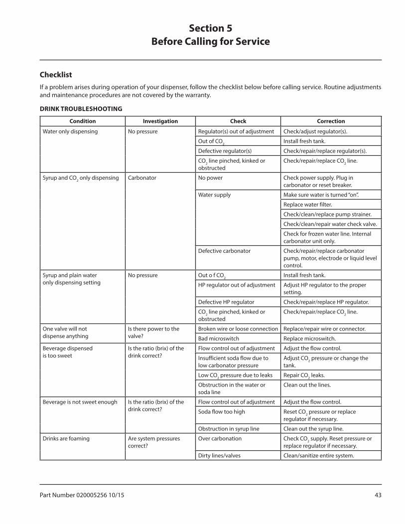
ChecklistIf a problem arises during operation of your dispenser, follow the checklist below before calling service. Routine adjustments and maintenance procedures are not covered by the warranty.
DRINK TROUBLESHOOTING
Condition Investigation Check Correction
Water only dispensing No pressure Regulator(s) out of adjustment Check/adjust regulator(s).
Out of CO2 Install fresh tank.
Defective regulator(s) Check/repair/replace regulator(s).
CO2 line pinched, kinked or obstructed
Check/repair/replace CO2 line.
Syrup and CO2 only dispensing Carbonator No power Check power supply. Plug in carbonator or reset breaker.
Water supply Make sure water is turned “on”.
Replace water filter.
Check/clean/replace pump strainer.
Check/clean/repair water check valve.
Check for frozen water line. Internal carbonator unit only.
Defective carbonator Check/repair/replace carbonator pump, motor, electrode or liquid level control.
Syrup and plain wateronly dispensing setting
No pressure Out o f CO2 Install fresh tank.
HP regulator out of adjustment Adjust HP regulator to the proper setting.
Defective HP regulator Check/repair/replace HP regulator.
CO2 line pinched, kinked or obstructed
Check/repair/replace CO2 line.
One valve will notdispense anything
Is there power to thevalve?
Broken wire or loose connection Replace/repair wire or connector.
Bad microswitch Replace microswitch.
Beverage dispensedis too sweet
Is the ratio (brix) of thedrink correct?
Flow control out of adjustment Adjust the flow control.
Insufficient soda flow due to low carbonator pressure
Adjust CO2 pressure or change the tank.
Low CO2 pressure due to leaks Repair CO2 leaks.
Obstruction in the water or soda line
Clean out the lines.
Beverage is not sweet enough Is the ratio (brix) of the drink correct?
Flow control out of adjustment Adjust the flow control.
Soda flow too high Reset CO2 pressure or replace regulator if necessary.
Obstruction in syrup line Clean out the syrup line.
Drinks are foaming Are system pressures correct?
Over carbonation Check CO2 supply. Reset pressure or replace regulator if necessary.
Dirty lines/valves Clean/sanitize entire system.
Section 5Before Calling for Service
44 Part Number 020005256 10/15
Before Calling for Service Section 5
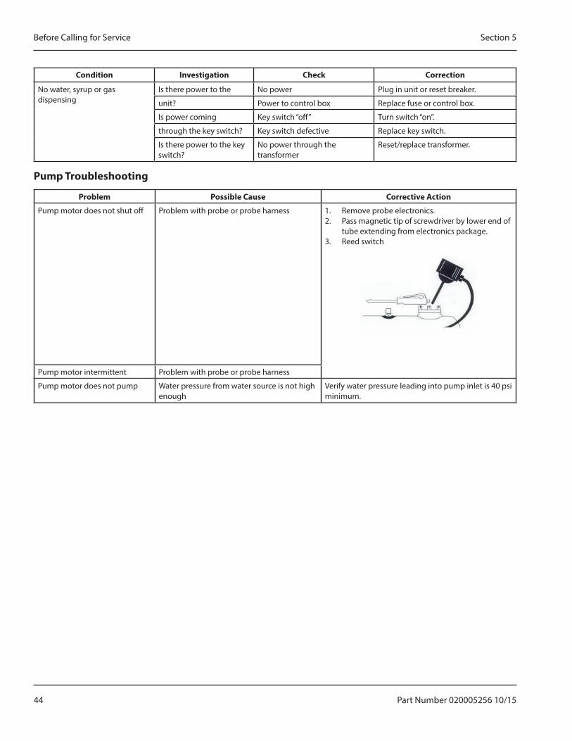
Condition Investigation Check Correction
No water, syrup or gas dispensing
Is there power to the No power Plug in unit or reset breaker.
unit? Power to control box Replace fuse or control box.
Is power coming Key switch “off” Turn switch “on”.
through the key switch? Key switch defective Replace key switch.
Is there power to the key switch?
No power through the transformer
Reset/replace transformer.
Pump Troubleshooting
Problem Possible Cause Corrective Action
Pump motor does not shut off Problem with probe or probe harness 1. Remove probe electronics.2. Pass magnetic tip of screwdriver by lower end of
tube extending from electronics package.3. Reed switch
Pump motor intermittent Problem with probe or probe harness
Pump motor does not pump Water pressure from water source is not high enough
Verify water pressure leading into pump inlet is 40 psi minimum.
Part Number 020005256 10/15 45
Section 5 Before Calling for Service
THIS PAGE INTENTIONALLY LEFT BLANK
46 Part Number 020005256 10/15
Before Calling for Service Section 5
THIS PAGE INTENTIONALLY LEFT BLANK

SERVEND 2100 FUTURE, SELLERSBURG, IN 47172
800-367-4233 WWW.MANITOWOCBEVERAGE.COM/US
To learn how Manitowoc Foodservice and its leading brands can equip you, visit our global web site at www.manitowocfoodservice.com, then discover the regional or local resources available to you.
©2014 Manitowoc Foodservice except where explicitly stated otherwise. All rights reserved. Continuing product improvement may necessitate change of specifications without notice.
Part Number 020005256 10/15
Every new piece of Manitowoc Foodservice equipment comes with KitchenCare™ and you choose the level of service that meets your operational needs from one restaurant to multiple locations.
StarCare – Warranty & lifetime service, certified OEM parts, global parts inventory, performance auditedExtraCare — CareCode, 24/7 Support, online/mobile product informationLifeCare – Install & equipment orientation, planned maintenance, KitchenConnect™, MenuConnectTalk with KitchenCare™ • 1-844-724-CARE • www.mtwkitchencare.com
®