Embed Size (px)
Citation preview
Notes for Guidance Direct Fired Air Heaters Application and Installation Preface The attached notes for guidance are extracted from B.S. 6230: 1982 'Specification for installation of gas fired forced air heaters for commercial and industrial space heating of rated input exceeding 60 kW (2nd family gases)' and are those which apply to Direct Fired Heaters only, as the specification also deals with Indirect Fired Heaters.
In addition your attention is drawn to the following: -
a) Building Regulations 1985 Approved Document J
In addition to B.S. 6230 the following standards also apply with regard to the building and appliance.
B.S. 5345: Code of practice for the selection, installation and maintenance of electrical apparatus for the use in potentially explosive atmospheres (other than mining applications or explosive processing and manufacture)
B.S. 5720: Code of practice for mechanical ventilation and air conditioning in buildings.
B.S. 5925: Code of practice for design of buildings; ventilation principles and designing for natural ventilation.
E.H.22: Health and Safety Executive Guidance Note 1979 Ventilation of Buildings: (fresh air requirements).
British Gas PLC Publications
IM/16: 1988 Guidance notes for the installation of gas pipework, boosters and compressors in customers premises (excluding domestic installation of 25mm and below)
IM/21: 1984 The Gas Safety (Installation and Use) Regulations 1984
1. General Application
Direct fired heaters are suitable for many applications; however there are some limitations due to the presence of combustion products in the heated air and these are as follows:
a) The total installation, that is the combination of the heater or heaters and the ventilation facilities in the room or rooms supplied with heated air shall be designed and operated such that the concentration of Carbon Dioxide at positions
where the air is normally inhaled by persons present shall not exceed 0.28% (2800 parts per million by volume, vpm).
Note: This is approximately equivalent to one volume of products to 38 volumes of outside air supplied to the spaces being heated, calculated on the basis of the same temperature. The concentration of Carbon Dioxide is also approximately equivalent to a maximum nett heat input by direct firing of 84 kJ/m3 of outside air that enters the room per hour. (see appendix 1). Where air extraction is not wholly achieved by positive means, for example where it is by either relief grilles or partly by fans, knowledge of the air change rate of the room concerned is required in order to assess the maximum heat input that avoids excessive Carbon Dioxide concentrations.
b) In rooms where products of combustion are present from sources other than from the direct fired heater system, for example releases from unflued small appliances, the maximum values of combustion product concentrations shall include these local ambient levels. This may limit or preclude the use of direct fired heaters in some locations. (see appendix 1).
c) Direct fired heaters shall not be installed in hazardous areas, although they may be permitted to supply heated air to such areas.
d) Direct fired air heaters may be permitted to be used in applications where the normal concentrations of flammable vapours are below threshold limit values (cf BS 5925 clauses 3.11 and 3.12) e.g. most workshops, laboratories and garages.
e) Direct fired air heaters shall not be used in applications where flammable vapours can be pre- sent in excess of their threshold limit values, as defined in BS 5925, e.g. some vehicle repair shops and process rooms, unless all air supplied to the heater is fresh air.
f) Heaters intended for intermittent use e.g. door curtain heaters, shall not be installed to operate continuously where combustion product concentrations higher than those specified in BS 6230 would be produced and sustained in inhalation levels. A system that ensures that the heater operates intermittently e.g. door position interlocks shall be fitted to such installations.
2. Installation 2.1 Siting
In addition to the usual conditions applying to the siting of air heaters the following conditions must be observed.
a) Heaters supplying air to hazardous areas where flammable vapours may be present in concentrations exceeding 25% of their lower explosive limit but where
the space to be heated does not constitute a hazardous area, shall not be sited within the space, unless: (i) All incoming air to the heater is fresh air. (ii) The base of the heater is at least 1.8m above floor level.
b) Heaters supplying air to hazardous areas, or to areas where flammable vapours may be pre- sent in concentrations exceeding 25% of their lower explosive limit, shall be installed in a separate room or compartment that is attached to or within the zoned hazardous area, such rooms or compartments being constructed as specified in BS 476 Part 8. Note: For such applications it is recommended that whenever reasonably practicable the heater should be sited out- side the space to be heated either in the open air or in a separate room or compartment.
2.2 Plant Rooms or Compartments
a) Where natural ventilation is used, openings communicating directly with the outside air should be provided. The openings fitted with grilles of negligible resistance should be sited so that they cannot be easily blocked or flooded. They shall have a total minimum free area as follows: Low level (inlet) 320cm2 + 2.7cm2 /kW in excess of 60 kW total rated input. High level (output) 160cm2 + 1.35cm2 /kW total rated input.
The free area of the grilles shall not be less than the size of the recommended minimum ventilation opening. Grilles shall be designed to minimise high velocity air streams in the plant room. For exposed i.e. free standing plant rooms, ventilation openings shall be provided on at least two sides and preferably on all four sides.
b) Where mechanical ventilation is used it shall be by mechanical input and either natural or mechanical extraction. Systems of ventilation employing mechanical extraction and natural input shall not be used. The minimum flow rates of air supplied shall not be less than O.6m3/s per megawatt of rated heat input. Where fresh air and heated extract fans are fitted for building ventilation, interlocks shall be provided so direct fired air heater(s) will not operate unless sufficient fans are in operation to provide adequate ventilation to keep the Carbon Dioxide concentration below the specified maximum of 0.28% (2800 v pm).
c) In direct fired air heater installations where there is dependence on natural ventilation and this ventilation has means of adjustment, or closing, such that there is likelihood that incorrect use could result in higher concentrations of Carbon Dioxide than specified, interlocks shall be provided to prevent operation of air heater(s) except when the ventilation means is correctly set.

3. Gas Supplies and Pipework
All gas supplies and pipework must conform to 1 M/16 : 1988 and the Gas Safety Regulations both in design and installation.
Before connection of the direct fired air heater(s) to an existing gas meter the appropriate Gas Board shall be consulted to ensure that the service meter supply capacity is adequate for the proposed new appliance(s).
4. Electrical
All wiring external to the heater shall be in accordance with the IEE Wiring Regulations (15th Edition), the appropriate British Standards, and any local Regulations which apply.
5. Selection of Appliance
Appendix 1 gives the method of determining the feasibility of applying direct fired air heaters. Two cases are given for the same building viz:
Case 1. With 10 air changes. Case 2. With 1.5 air changes.
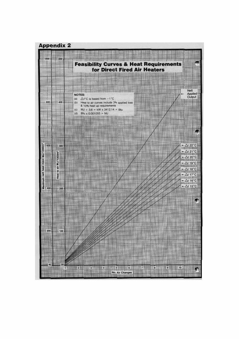
As can be seen in Case 1 all heating requirements can be met solely with a direct fired appliance. However in Case 2, the requirements cannot be met solely with a direct fired appliance. These two cases demonstrate the use of the 84 kJ/m3 maximum nett heat input of a direct fired appliance to ensure the 0.28% Carbon Dioxide level. This appendix however also shows the method adopted to apply the option of increased air change rate to permit the use of direct fired heaters. Appendix 2 presents the method used in Case 1 in graphical form which can be used as a feasibility and selection chart, the temperature differences are from -1°C, and all heat requirements are based on 1000m3 and number of air changes. In order to use this graph to determine the feasibility the client would be required to answer 4 basic questions viz :-
1. What is the building volume. 2. What are the number of air changes. 3. What air temperature is required. 4. What are the building fabric losses.
Using Case 1 from Appendix 1 the answers would be: 1. 1800m3 2. 10 3. 20°C
4. 264 MJ/h From graph at 10 air changes.
1. Max nett direct fired input =840MJ/h/10003 ∴ 18003 = 840 x 1.8 = 1512MJ/h
2. Heat to air at 21°C =287MJ/h/10003 ∴ 18003 = 287 x 1.8 =517MJ/h
3. Maximum permissible fabric loss is 1512- 517 =995MJ/h
4. The quoted fabric loss is 264MJ/h to which must be added 3% and then 10%, which then becomes 299MJ/h.
5. As the graph shows a maximum permissible fabric loss of 995MJ/h and the actual loss is 299MJ/h then a direct unit is feasible. 6. The use of direct firing can be finally confirmed thus:
From graph heat to air = 517MJ/h Specified fabric loss =299MJ/h Total =816MJ/h Max nett direct fired input from graph = 1512MJ/h
7. Finally gross input is calculated by
nett output/0.9 viz 816/0.9 = 906.6MJ/h
Note: The slope of the nett input line is equal to 0.28% (2800 v pm) Carbon Dioxide.
6. Appliance checks to be carried out prior to commissioning
The following is a typical list of appliance checks to be carried out prior to commissioning the burner: a) check that the manual gas valves are in closed position and that suitable warning
notices are attached; b) check that all electrical supplies are isolated and that suitable warning notices are
attached: c) check and adjust fan belt tensions; d) check that filter assemblies are inserted and correctly located (where fitted); e) check electrical earth continuity between the appliance, gas pipework and the mains supply; f) check that electrical components are of correct voltage range, particularly low
voltage ancillary controls; g) check that the direction of rotation of the fan(s) is correct and that the fan(s) is
moving freely;
h) check fan motor currents and adjust starter overload settings; i) check and adjust setting of air discharge grilles; j) check operation and interlocking of extract and fresh air supply fans (where
appropriate); k) check and adjust air flow failure switch(es); I) check for correct connection and operation of all external components, e.g. thermostats, time switches, damper interlocks etc.; m)check the soundness of the connections and pipework on the appliance, using leak
detection fluid, e.g. soap solution n) ensure that the gas installation pipework to the appliance has been tested for
soundness.
7. Typical live run checks
The following is a typical list of live run checks to be carried out in the commissioning procedure. a) After a faultless dry run, make gas available to the start gas burner on the
appliance to check the correct operation of the ignition system; this will require the isolation of the main burner gas supply.
b) Simulate pilot or start gas flame failure and check that the flame safeguard system proceeds to lockout, e.g. by turning off the pilot gas supply.
c) After checking that the start gas flame is correctly sited and adequate to light the main flame, then allow gas to flow to the burner after also having ensured that there is adequate combustion air avaialble.
d) If the main flame fails to ignite, repeat the complete lighting procedure whilst ensuring that adequate time is allowed to purge the combustion chamber.
e) The burner is then sequenced between high and low fire and all controls and interlocks checked for correct operation.
f) The gas rate to the appliance is checked, e.g. by using the customer's primary meter. g) The level of combustion products in the environment is then tested.
Appendix 1 Limitations of application of direct-fired air heaters in buildings
1.1 General. This appendix describes two very brief case studies that show how the figure of 84 KJ per cubic metre of outside air is used when calculating the amount of direct-fired heating that can be permitted when related to the air change rates. For these studies it is assumed that a building:
a) has dimensions of 15m x 30m x 4m and thus an internal volume of 1800m³;
b) has a structural heat loss of 264 MJ/h; c) is to be designed for a temperature of 20°C based on a minimum outside temperature of -1°C.
The following simplified equation is used to calculate the heat requirement, H, (in MJ/h) of the incoming air:
H = AVST x 10-3 where
A is the number of air changes per hour; V is the room volume (in m3); S is the heat capacity, volume basis, of air (taken as 1.207 kJ/m³.K)); T is the temperature difference (in K).
1.2 Case 1. The building requires 10 fresh air changes per hour. The heat required to raise the temperature of the fresh air is:
H = 10 x 1800 x 1.207 x (20 - ( -1 )) x 1 0-3 = 456 MJ/h
The total heat requirement of the building is: 264 + 456 = 720 MJ/h (1) Next the actual nett total heat input of the appliance is calculated.
Actual nett input accordingly is:
720 x (103/100) x (110/100) = 816MJ/h (2)
But the maximum nett heat output allowed by direct-firing is 84 kJ per cubic metre of fresh air change per hour, which for this building's air change rate is:
84 x 10 x 1800 x 10-3 = 1512 MJ/h (3) By comparing (2) and (3) it can be seen that the building can be heated solely by a direct-fired
system. The gross heat input of the heater can now be calculated from an assumed ratio of nett to gross calorific value of 90 : 100. Gross heat input to appliance therefore is:
816 x 100/90 = 907MJ/h
1.3 Case 2 1.3.1 Consider the same building as in Case 1 but with only 1.5 air changes per hour. The heat required to raise the temperature of the fresh air is:
H =1.5 x 1800 x 1.207 x (20- (-1)) x 10-3
= 68 MJ/h The total heat requirement of the building is:
264 + 68 = 332 MJ/h (4) But the maximum nett heat output allowed by direct-firing is 84 kJ per cubic metre of fresh air change per hour, which for this building's air change rate is:
84 x 1.5 x 1800 x 10-3 = 226 MJ/h (5) By comparing (4) and (5) it can be seen that the building cannot be heated solely by direct-fired heating.
The maximum gross heat input to the direct-fired heater has to be calculated from the previously assumed ratio of net and gross calorific values. The gross heat input to the appliance is therefore:
226 x (100/90) = 251 MJ/h (6)
The quantity of heat available will need to be supplemented to allow for fast heat-up and to make up the deficit of 106 MJ/h (from (4)-(5) above). This total shortfall can be made up by indirect-fired heaters, of 75% assumed efficiency, sized as follows:
(332 x (10/100) + 106) x (100/75) = 186 MJ/h (7)
This gives a total connected heating appliance load of: 251 + 186 = 437 MJ/h (8)
1.3.2 An alternative available to the designer is to increase the air change rate to such an extent that all the heating requirements are satisfied by direct-fired heaters. The following equation then applies:
(L + QST x 10-3) x (110/100) x (103/100) = NQ x 10-3
Rearranging: Q= 1130L/((N - 1.13ST)
where L is the structural heat loss (in MJ/h) Q (=AV) is the air change volume (in m3/h) N is the maximum heat output allowed = 84 kJ/m3
The factor (110/100) provides for a fast heat-up allowance of 10%
The factor (103/100) provides for a case loss allowance of 3%
The air change volume in this case is therefore:
Q = (1130 x 264)/84 - [1.13 x 1.207 x [20- (-1)]]
= 5389m3/h
The air change rate per hour is therefore:
5389/1800 ~ 3.0 The heat required to raise the temperature of the fresh air from -1°C to 20°C at 3.0 air changes per hour is:
3.0 x 1800 x (1.207/1000) x 21 = 137 MJ/h
Total building heat requirement is therefore:
264 + 137 = 401 MJ/h Thus the gross heat input to the direct-fired heater would be:
401 x (100/90) = 446 MJ/h
1.3.3 The use of a direct-fired heater giving an enhanced air change rate results in a connected load approximately 2% greater than that required for a combination of direct and indirect-fired air heaters. However, the method of increasing air change rate should be used with caution, since for some installations it may increase unduly the fuel consumption and connected gas load.


![k|wfg ;]gfkltsf] sdf08 dfu{ lgb]{zg – @)&@ · k|wfg ;]gfkltsf] sdf08 dfu{ lgb]{zg – @)&@ COAS’s Command Guidance - 2015 cjlu{s[t efux¿ dfq](https://img.dokumen.tips/doc/110x75/5ecbe2f1b562956e4161f489/kwfg-gfkltsf-sdf08-dfu-lgbzg-a-kwfg-gfkltsf-sdf08-dfu-lgbzg.jpg)