Embed Size (px)
Citation preview

DeZURIK PEF 100% PORT ECCENTRIC PLUG VALVES
TECHNICAL SPECIFICATIONS
BULLETIN 12.60-1B
FEBRUARY 2012

Item Description Material A1 Body Cast Iron, ASTM A126, Class B
A2 Body Bearing 316L Stainless Steel. Sintered Stainless Steel
Metal, (Ductile Iron, ASTM A536, Grade 65-45-12)
Plug CR Chloroprene
NBR Acrylonitrile-Butadiene
A4 Grit Excluder PTFE
A5 O-Ring Non-asbestos filler in Styrene-Butadiene Rubber binder (NBR)
A6 Bonnet Cast Iron, ASTM A126, Class B
A7 Bonnet Bearing 316L Stainless Steel, Sintered Stainless Steel
Carbon Steel, Class 8.8, Zinc Plated
Bonnet Screws Stainless Steel, Grade A2, (18-8)
Stainless Steel, Grade A4, (316)
Packing NBR Acrylonitrile-Butadiene, V-Type
A10 Key Steel, ASTM A108
A11 Gland Cast Iron, ASTM A126, Class B
Carbon Steel, Class 8.8, Zinc Plated
A12 Gland Stud Stainless Steel, Grade A2, (18-8)
Stainless Steel, Grade A4, (316)
Carbon Steel, Zinc Plated
A13 Nut Stainless Steel, A2, (18-8)
Stainless Steel, A4, (316)
A14 Caution Tag Stainless Steel
A15 Pipe Plug (optional) Galvanized Carbon Steel
A16 O-Ring Non-asbestos filler in Styrene-Butadiene Rubber binder (NBR)
A17 Journal Cover Cast Iron, ASTM A126, Class B
Carbon Steel, Class 8.8, Zinc Plated
Screw Stainless Steel, Grade A2, (18-8)
Stainless Steel, Grade A4, (316)
A21 Friction Cone Ryton
A23 Pipe Plug (optional)
Materials of Construction
©2012 DeZURIK
* Patent Pending
Flanged Construction3" (80mm) and Larger
A3
A8
A9
DeZURIK PEF 100% Port Eccentric Plug Valves are designed and/or tested to meet the following standards: AWWA C517-05 Resilient-Seated Cast-Iron Eccentric Plug Valve.
ANSI flange drilling conforms to ANSI B16.1, Class 125 and ANSI B16.5, Class 150. Mechanical-joint end connections conform to ANSI/AWWA C111/A21.11. MSS-SP91 guidelines for manual operation of valves. Metric 10 bar flange drilling conforms to the NP 10 requirements of International Standard ISO 2084, to the 10 bar requirements of British Standard 4504, and to the NP 10 requirements of German Standard DIN 2532. Metric 16 bar flange drilling conforms to the NP 16 reguirements of International Standard ISO 2084, to the 16 bar requirements of British Standard 4504, and to the NP 16 requirements of German Standard DIN 2533.
British Table D flange drilling and Table E flange drilling conform to British Standard BS 10. Japanese 10 bar flange drilling conforms to Japanese Industrial Standard JIS B 0203.
2
A18
Applicable Standards
A12
A11
A21
A9
A13A15
A18
A17
A16
A1
A23
A2
A4
A3
A4
A5
A7
A14A6
A8
A9
A11
A12
A13
A10
Galvanized Carbon Steel
316 Stainless Steel

Valve Selection
* Cast Iron conforms to ANSI B16.1 Class 125 Hydrostatic Test.
3" 880 80mm 760
4" 1160 100mm 1000
5 & 6" 1960 125 & 150mm 1700
8" 3100 200mm 2680
10" 4540 250mm 3930
12" 6300 300mm 5450
14" 7560 350mm 6530
16" 9840 400mm 8500
18" 12500 450mm 10800
20" 15400 500mm 13300
24" 41400 600mm 35800
30" 65500 750mm 56600
36" 95100 900mm 82200
Cv/Kv Values
Valve Size
Cv* Kv*
* Cv = Flow in GPM of water at 1 psi pressure drop. * Kv = Flow in m3/hr. of water at 100 kPa pressure drop.
3" 57 60 80mm 26 27 4" 72 82 100mm 33 37
5" 120 N/A 125mm 54
6" 120 138 150mm 54 63
8" 185 207 200mm 84 94
10" 264 296 250mm 120 134
12" 375 395 300mm 170 179
14" 555 595 350mm 252 270
16" 698 784 400mm 317 356
18" 1015 1091 450mm 460 495
20" 1340 1389 500mm 608 630
24" 3160 2984 600mm 1433 1354
30" 5305 5145 750mm 2406 2334
36" 8225 8110 900mm 3731 3679
Basic Valve Weights
Valve Size
Flangedlbs/kg
M.J.lbs/kg
Note: Basic Valve – is a fully assembled bare shaft valve
Cast Iron 175 psi 150 psi (ASTM A126-Grade B) 1210 kPa 1035 kPa
C.W.P. Non-Shock Working Pressure Ratings
Pressure Ratings
Valve Size
Material 3–12"(80–
300mm)
14–36" (350–
900mm)
citsiretcarahC wolF
0
01
02
03
04
05
06
07
08
09
001
0010908070605040302010
nepO tnecreP evlaV
Per
cen
t o
f M
axim
um
Flo
w
)"02 - "3( )"63 - "42(
Flow Characteristic100%
90%
80%
70%
60%
50%
40%
30%
20%
10%
0%
Per
cen
tag
e o
f M
axim
um
Flo
w
0% 10% 20% 30% 40% 50% 60% 70% 80% 90% 100%Valve Percent Open
3
Temperature Rating180°F continuous max temp rating.

Installation InstructionsClean Liquids and Clean GasesThe proper installation of a DeZURIK PEF 100% Eccentric Plug Valve in clean liquids and gases applications is with the higher pressure against the end opposite the seat.
4
Liquids with Suspended Solids and Dirty GasesThe proper installation of a DeZURIK PEF 100% Eccentric Plug Valve in suspended solids applications such as raw sewage is critical to prevent solids from packing into the valve body, restricting the plug movement. This can be accomplished by installing the valve with the flow against the face of the plug in the closed position and the valve on its side with the plug rotating to the top of the pipeline in the open position. For pump isolation service, install the discharge valve with the seat downstream from the pump and the plug rotating to the top of the pipeline in the open position.

Valve Sizing Flow Charts
Valve Fully Open Valve Fully Open - Metric
Pressure Drop (psi) Pressure Drop (kPa)
Flo
w T
hro
ug
h V
alve
(G
PM
)
Flo
w (
m3 /
hr)
5

Valve StyleGive valve style code as follows: PEF = 100% Port Eccentric Plug
Valve SizeGive valve size code as follows:
3 = 3" (80mm) 14 = 14" (350mm)
4 = 4" (100mm) 16 = 16" (400mm)
5 = 5" (125mm) 18 = 18" (450mm)
6 = 6" (150mm) 20 = 20" (500mm)
8 = 8" (200mm) 24 = 24" (600mm)
10 = 10" (250mm) 30 = 30" (750mm)
12 = 12" (300mm) 36 = 36" (900mm)
Body MaterialGive body material code as follows:
CI = Cast Iron
Options
DST = Dry Seat Test
PD = 1/4" Pipe Tap Downstream (See note)
PU = 1/4" Pipe Tap Upstream (See note)
PDU = 1/4" Pipe Tap Downstream and Upstream
GR = Grease Fittings in Body & Bonnet
(Flanged Valves only) not available with ENK extension
– – = Optional coating
Note: If both PD and PU are required, a six digit modifier must be used.
End ConnectionGive end connection code as follows:
F1 = Flanged, ANSI Class 125/150
F110 = Flanged, ANSI Class 150, DIN 10 or B54504/10
F116 = Flanged, ANSI Class 150, DIN 16 or B54504/16
F1D = Flanged, ANSI Class 150, BS Table D
F1E = Flanged, ANSI Class 150, BS Table E
F1J1 = Flanged, ANSI Class 150, JIS Drilling
MJ = Mechanical Joint (Not Available on 5")
Plug Facing Give plug facing code as follows:Standard facings:CR = Chloroprene (RS 16/17) -20 to 180ºF (-29 to 83ºC)
CIIR = Chloro-Isobutene Isoprene (RS55/56)
-20 to 250ºF (-29 to 121ºC)
NBR = Acrylonitrile-Butadiene (RS24/25) -20 to 180ºF (-29 to 83ºC)
PackingGive packing code as follows:
NBR = Acrylonitrile-Butadiene V-Type Multiple V-Ring -20 to 180ºF (-29 to 83ºC)
OrderingTo order, simply complete the valve order code from information shown. An ordering example is shown for your reference.
Ordering Example: PEF,8,F1,CI,NBR,CR*GS-6A-HD8
Note: The limiting factor in valve selection is the lowest temperature limit of the packing or seat.
6
Order Code Size ACC*CHA-3 3" (80mm)
ACC*CHA-4 4" (100mm)
ACC*CHA-5 5" (125mm)
ACC*CHA-6 6" (150mm)
ACC*CHA-8 8" (200mm)
Order Code Size ACC*LVA-3 3" (80mm)
ACC*LVA-4 4" (100mm)
ACC*LVA-5 5" (125mm)
ACC*LVA-6 6" (150mm)
ACC*LVA-8 8" (200mm)
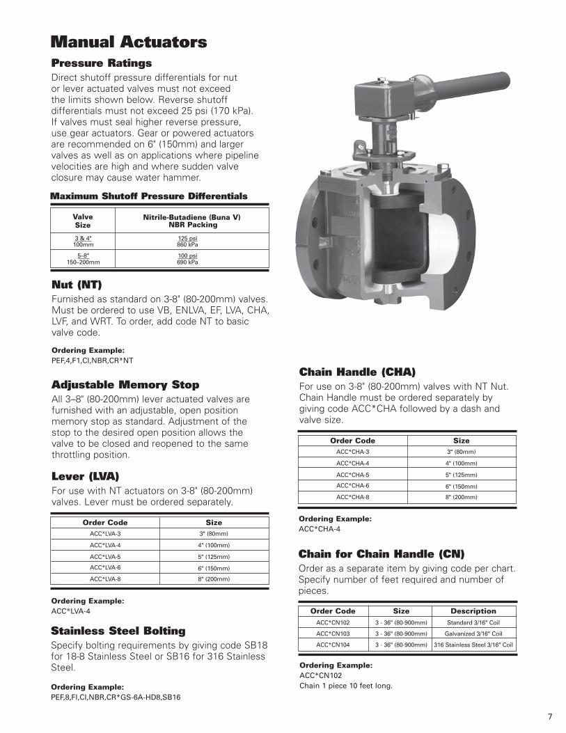
Manual Actuators
Nut (NT)Furnished as standard on 3-8" (80-200mm) valves. Must be ordered to use VB, ENLVA, EF, LVA, CHA, LVF, and WRT. To order, add code NT to basic valve code.
Ordering Example: PEF,4,F1,CI,NBR,CR*NT
Adjustable Memory StopAll 3–8" (80-200mm) lever actuated valves are furnished with an adjustable, open position memory stop as standard. Adjustment of the stop to the desired open position allows the valve to be closed and reopened to the same throttling position.
Lever (LVA) For use with NT actuators on 3-8" (80-200mm) valves. Lever must be ordered separately.
Chain Handle (CHA)For use on 3-8" (80-200mm) valves with NT Nut. Chain Handle must be ordered separately by giving code ACC*CHA followed by a dash and valve size.
Chain for Chain Handle (CN)Order as a separate item by giving code per chart. Specify number of feet required and number of pieces.
Stainless Steel BoltingSpecify bolting requirements by giving code SB18 for 18-8 Stainless Steel or SB16 for 316 Stainless Steel. Ordering Example:
ACC*CN102Chain 1 piece 10 feet long.Ordering Example:
PEF,8,FI,CI,NBR,CR*GS-6A-HD8,SB16
Ordering Example: ACC*LVA-4
Pressure RatingsDirect shutoff pressure differentials for nut or lever actuated valves must not exceed the limits shown below. Reverse shutoff differentials must not exceed 25 psi (170 kPa). If valves must seal higher reverse pressure, use gear actuators. Gear or powered actuators are recommended on 6" (150mm) and larger valves as well as on applications where pipeline velocities are high and where sudden valve closure may cause water hammer.
Maximum Shutoff Pressure Differentials
3 & 4" 125 psi
100mm 860 kPa
5–8" 100 psi
150–200mm 690 kPa
Valve Size
Nitrile-Butadiene (Buna V) NBR Packing
Order Code Size Description ACC*CN102 3 - 36" (80-900mm) Standard 3/16" Coil
ACC*CN103 3 - 36" (80-900mm) Galvanized 3/16" Coil
ACC*CN104 3 - 36" (80-900mm) 316 Stainless Steel 3/16" Coil
7
Ordering Example: ACC*CHA-4

Manual ActuatorsThe G-Series and MG manual actuators construction are totally enclosed and sealed, protecting moving parts from damage or corrosion. Continual lubrication is not required for operational ease. Heavy duty, corrosion-resistant actuator bearings provide lasting, easy valve operation and overall reliability. Rugged actuator castings, gears and shafts also add to reliability by assuring permanent alignment of moving parts for smooth operation.
To order, add the appropriate actuator code from the sizing tables to the valve order code. For buried service valves, substitute “GS” with “GB” and “MG” with “MGB”. If 2" (50mm) nut is required, see page 11.
Valve Size
Handwheel Order Code
Chainwheel Order Code
Max. Shutoff Pressure
Differential psi/kPa
50340
75520
1501030
100690
1501030
MG-MJ50-HD24 MG-MJ50-CW24
MG-MJ50-HD30* MG-MJ50-CW30*
MG-ML60-HD24 MG-ML60-CW24
MG-ML60-HD24 MG-ML60-CW24
MG-ML60-HD30 MG-ML60-CW30
20"500mm
30"750mm
36"900mm
Direct Pressure, Resilient Plug, Metal Seat
Valve Size
Handwheel Order Code
Chainwheel Order Code
Max. Shutoff Pressure
Differential psi/kPa
17512101751210
1751210
1751210
75520
125860
1751210
75520
125860
1751210
50340
100690
1501030
50340
75250
1501030
25170
50340
125860
1501030
25170
75250
1501050
75250
1501050
GS-6A-HD8 GS-6A-CW8
GS-6A-HD8 GS-6A-CW8
GS-6A-HD8 GS-6A-CW8
GS-6A-HD8 GS-6A-CW8
GS-6A-HD8 GS-6A-CW8
GS-6A-HD12 GS-6A-CW12
GS-12A-HD12 GS-12A-CW12
GS-6A-HD12 GS-6A-CW12
GS-12A-HD12 GS-12A-CW12
GS-12A-HD16 GS-12A-CW20
GS-12A-HD12 GS-12A-CW12
GS-12A-HD16 GS-12A-CW20
GS-12A-HD20 GS-12A-CW20
GS-12A-HD16 GS-12A-CW20
GS-12A-HD20 GS-12A-CW20
GS-12A-HD24* GS-12A-CW24
GS-12A-HD20 GS-12A-CW20
GS-12A-HD24* GS-12A-CW24
GS-12A-HD30 GS-12A-CW30
MG-MJ50-HD20 MG-MJ50-CW20
GS-12A-HD24* GS-12A-CW24
GS-12A-HD30* GS-12A-CW30*
MG-MJ50-HD24 MG-MJ50-CW24
MG-MJ50-HD12 MG-MJ50-CW12
MG-MJ50-CW24 MG-MJ50-CW24
4"100mm
5 & 6"125 & 150mm
8"200mm
10"250mm
12"300mm
14"350mm
16"400mm
18"450mm
8
3"80mm
24"600mm
Direct Pressure, Weatherproof Nut Actuator
Valve Size Order Code Max. Shutoff Pressure
Differential psi/kPa
1751210
1751210
1751210
1751210
1751210
1751210
1501030
1501030
125860
1501035
75515
1501035
1501035
75520
1501035
1501035
GS-6A-N
GS-6A-N
GS-6A-N
GS-6A-N
GS-6A-N
GS-6A-N
GS-12A-N
GS-12A-N
GS-12A-N
MG-MJ50-N
GS-12A-N
MG-MJ50-N
MG-MJ50-N
MG-MJ50-N
MG-ML60-N
MG-ML60-N
5 & 6"125 & 150mm
8"200mm
10"250mm
12"300mm
14"350mm
16"400mm
18"450mm
4"100mm
20"500mm
3"80mm
24"600mm
30"750mm
36"900mm
Ordering Example: PEF,6,F1,CI,NBR,CR*GB-6A-N PEF,14,F1,CI,NBR,CR*GS-12A-N
*Mounting positions 90 & 270 not available

Reverse Pressure, Resilient Plug, Metal Seat
Valve Size
Handwheel Order Code
Chainwheel Order Code
Max. Shutoff Pressure
Differential psi/kPa
1751210
1751210
1751210
125860
1751210
75520
1501030
1751210
25170
75520
1501030
1751210
25170
75520
100690
1501030
25170
50340
125860
1501030
25170
50340
75520
1501030
50340
1501050
50340
100690
1501050
50340
75520
1501030
100690
1501030
GS-6A-HD8 GS-6A-CW8
GS-6A-HD8 GS-6A-CW8
GS-6A-HD8 GS-6A-CW8
GS-6A-HD8 GS-6A-CW8
GS-6A-HD12 GS-6A-CW12
GS-6A-HD12 GS-6A-CW12
GS-12A-HD12 GS-12A-CW12
GS-12A-HD16 GS-12A-CW20
GS-6A-HD12 GS-6A-CW12
GS-12A-HD12 GS-12A-CW12
GS-12A-HD16 GS-12A-CW20
GS-12A-HD20 GS-12A-CW20
GS-12A-HD12 GS-12A-CW12
GS-12A-HD16 GS-12A-CW20
GS-12A-HD20 GS-12A-CW20
GS-12A-HD24* GS-12A-CW24*
GS-12A-HD16 GS-12A-CW20
GS-12A-HD20 GS-12A-CW20
GS-12A-HD24 GS-12A-CW24*
MG-MJ50-HD12 MG-MJ50-CW12
GS-12A-HD20 GS-12A-CW20
GS-12A-HD24 GS-12A-CW24
GS-12A-HD30 GS-12A-CW30*
MG-MJ50-HD24 MG-MJ50-CW24
GS-12A-HD30* GS-12A-CW30*
MG-MJ50-HD24 MG-MJ50-CW24
MG-MJ50-HD12 MG-MJ50-CW12
MG-MJ50-HD24 MG-MJ50-CW24
MG-MJ50-HD30* MG-MJ50-CW30*
MG-MJ50-HD24 MG-MJ50-CW24
MG-MJ50-HD30* MG-MJ50-CW30*
MG-ML60-HD24 MG-ML60-CW24
MG-ML60-HD24 MG-ML60-CW24
MG-ML60-HD30 MG-ML60-CW30
5 & 6"125 & 150mm
8"200mm
10"250mm
12"300mm
14"350mm
16"400mm
18"450mm
4"100mm
20"500mm
9
3"80mm
24"600mm
30"750mm
36"900mm
Reverse Pressure, Weatherproof Nut Actuator
Valve Size Order Code Max. Shutoff Pressure
Differential psi/kPa
1751210
1751210
1751210
1751210
1751210
1751210
1501030
125860
75520
1501035
50340
1501035
1501035
75520
1501035
1501035
GS-6A-N
GS-6A-N
GS-6A-N
GS-6A-N
GS-6A-N
GS-6A-N
GS-12A-N
GS-12A-N
GS-12A-N
MG-MJ50-N
GS-12A-N
MG-MJ50-N
MG-MJ50-N
MG-MJ50-N
MG-ML60-N
MG-ML60-N
5 & 6"125 & 150mm
8"200mm
10"250mm
12"300mm
14"350mm
16"400mm
18"450mm
4"100mm
20"500mm
3"80mm
24"600mm
30"750mm
36"900mm
Ordering Example: PEF,24,F1,CI,NBR,CR*MG-MJ50-N PEF,36,F1,CI,NBR,CR*MGB-MJ60-N
*Mounting positions 90 & 270 not available

FSDIR and FSDIU Floor Stand for Gear Actuated ValvesFor use on 3–36" (80–900mm) handwheel actuated valves. Includes floor stand, couplings, extension rod, and handwheel mounted on floor stand, with dial position indicator. Order floor stand by adding FSDIR or FSDIU to the valve actuator code.
Ordering Example: PEF,6,F1,NBR,CR*,GS-6A-HD12,FSDIR
Accessories-Manual ActuatorsEFA Extension for Nut Actuated Valves For use on 3–8" (80–200mm) valves. Includes extension pipe, bearing plate and couplings. Valves for use with EFA extensions must be ordered with NT actuators. Order Extension Assembly as a separate item. Specify length from centerline of valve to bottom of bearing plate. When ordering for use with FS101 Floor Stand, give dimension from centerline of valve to base of floor stand.
Ordering Example: ACC*EF-4Centerline of valve to bottom of bearing plate 110" (2795mm).
EF
FS101 Floor Stand for Nut Actuated Valves For use on 3–8" (80–200mm) nut actuated valves. Includes floor stand only. For extension pipe and fittings, order EFA Extension Assembly. Lever actuated valves for use with EFA Extension and FS101 Floor Stand must be ordered NT actuators. Order floor stands as a separate item.
Ordering Example: ACC*FS101
FS101
FB Floor Box for Nut Actuated ValvesIncludes floor box and cover only. Can be used with valves having operating nut mounted on the valve or extended with top of nut 2" (50mm) from top of floor box. All valves for use with floor boxes are Tee Wrench actuated (order separately). Order extended operating nuts (ENLVA) separately. Floor box requires NT actuators (order seperately). Order floor boxes separately. Specify ACC*FB and depth of floor box in 1" (25mm) increments from 6–18" (150–455mm). Standard depth is 6" (150mm).
Ordering Example: ACC*FB6
ENLV
FB
Ordering Example: ACC*ENLVA-8Centerline of valve to top of valve nut 126" (3200mm).
ENLVA Extended Nut for Nut Actuated Valves For use on 3–8" (80–200mm) nut actuated valves. Includes operating nut, couplings and pipe. Valves for use with ENLVA Extended Nut must be ordered with NT actuators. All valves for use with ENLVA are Tee Wrench activated (order seperately). Order as a separate item by giving ACC*ENLVA followed by a dash and valve size. Give required length from centerline of valve to top of nut. Note dimensions in table.
Minimum Dimension C/L of Valve to Top of Nut
3" 16.19" 80mm 411mm
4" 16.69" 100mm 424mm
5–6" 19.12" 125–150mm 486mm
8" 22.38" 2000mm 570mm
Valve Size
10
FSDIR FSDIU
Centerline of valve to base of floor stand 90" (2400mm).

ENK Neck Extension for G-Series ActuatorsValves for buried or submerged service can be furnished with handwheel or cylinder actuators extended above the ground. Furnish service information for recommendations.
ENK
ENGS Extended 2" (50mm) Nut for Gear Actuated ValvesThe ENGS is for use on 3–36" (80–900mm) PEF Eccentric Plug Valves with G-Series and MG Handwheel Manual Actuator. Includes couplings, extension rod and 2" (50mm) square nut. If used with valve box, top of nut must be 6" (150mm) below grade. If used with floor box, top of nut must be 2" (50mm) below floor surface. Handwheels are not furnished on actuators ordered with ENGS. Order by adding ENGS to the valve actuator code. Specify required length from centerline of valve to top of nut as second line information.
Ordering Example: PEF,6,F1,CI,NBR,CR*GB-6A-N,ENGS Centerline of valve to top of nut 72" (1830mm).
WRT Tee WrenchFor use on 3–8" (80–200mm) nut or gear actuated valves with 2" (50mm) nut. Valves for Tee Wrench operation must be ordered with NT actuator. Contact factory to order Tee Wrenches.
ENGS
2" (50mm) Nut on Gear ActuatorsThe nut replaces the handwheel normally supplied. A 2" (50mm) nut is required for use with valve box (VB) or floor box (FB). To order replace the handwheel code with “N”.
Ordering Example: PEF,6,F1,CI,NBR,CR*GB-6A-N
11
VB Valve Box for Nut Actuated Valves Valve boxes for use on 3–8" (80–200mm) valves require a nut (NT) or extended nut (ENLV) type actuator. Valve boxes for use on 3–36" (80–900mm) valves with a gear actuator (GB) require a 2" (50mm) Nut (N) or extended 2" (50mm) Nut (ENGS) actuator. Extended nut must be 6" (150mm) from the top of the valve box. Contact factory to order. VB
Accessories – Manual Actuators

Cylinder ActuatorsG-Series cylinder actuators feature a rack and pinion design for larger size rotary valves where constant torque capability throughout the stroke is required. It is engineered for high flow, high cycle applications. The G-Series line of actuators provides long service life and features a rugged, heavy cast gear sector. The cast iron actuator housing is sealed to prevent the entry of dirt, moisture and corrosive contaminants. The G-Series actuator also features adjustable position stops, rugged cylinder construction and corrosion-resistant bearings.
Double-ActingTo order double-acting cylinder actuators for PEF Eccentric Plug Valves, add the order code from the proper table to the valve order code. Actuators for 3–36" (80–900mm) valves can be mounted at 90 degree increments clockwise from standard. Specify mounting positions other than standard as second line information. When using hydraulic supply media, specify type. Please note, valves for gas service must be furnished with gear or cylinder actuator.
12
Direct Pressure, Resilient Plug, Metal Seat 50 psi (340kPa) Air Supply
* PC4 Cylinder not recommended with positioner
Valve Size
Actuator Code
Maximum Shutoff 50 psi
340 kPa
3"80mm
GS-6A-PC4* 1751210
GS-6A-PC6 1751210
4"100mm
GS-6A-PC4* 1751210
GS-6A-PC6 1751210
5 & 6"125 & 150mm
GS-6A-PC6 125860
GS-6A-PC8 1751210
8"200mm
GS-6A-PC6 50340
GS-6A-PC8 1501030
GS-12A-PC6 1751210
10"250mm
GS-6A-PC8 1501030
GS-12A-PC6 100690
GS-12A-PC8 1751210
12"300mm
GS-6A-PC8 25170
GS-12A-PC8 100690
GS-12A-PC10 1751210
14"350mm
GS-12A-PC8 50340
GS-12A-PC10 125860
O/A 1501030
16"400mm
GS-12A-PC10 50340
O/A 1501030
18"450mm
GS-12A-PC10 25170
O/A 1501030
20"500mm O/A 150
1030
24"600mm O/A 150
1030
30"750mm O/A 150
1030
36"900mm O/A 150
1030

Valve Size
Actuator Code
Maximum Shutoff 80 psi
550 kPa
3"80mm
GS-6A-PC4* 175 1210
GS-6A-PC6 175 1210
4"100mm
GS-6A-PC4* 175 1210
GS-6A-PC6 175 1210
5 & 6"125 & 150mm
GS-6A-PC4* 75 250
GS-6A-PC6 175 1210
8"200mm
GS-6A-PC6 125 860
GS-6A-PC8 175 1210
10"250mm
GS-6A-PC6 50 340
GS-6A-PC8 125 860
GS-12A-PC6 150 1030
GS-12A-PC8 175 210
12"300mm
GS-6A-PC6 25 170
GS-6A-PC8 75 520
GS-12A-PC6 100 690
GS-12A-PC8 175 1210
14"350mm
GS-12A-PC8 125 860
GS-12A-PC10 150 1030
16"400mm
GS-12A-PC8 50 340
GS-12A-PC10 125 860
O/A 150 1030
18"450mm
GS-12A-PC8 25 170
GS-12A-PC10 50 340
O/A 150 1030
20"500mm
GS-12A-PC10 25 170
O/A 150 1030
24"600mm O/A 150
1030
30"750mm O/A 150
1030
36"900mm O/A 150
1030
Cylinder Actuators Direct Pressure, Resilient Plug, Metal Seat 80 psi (550 kPa) Air Supply
Reverse Pressure, Resilient Plug, Metal Seat 50 psi (340 kPa) Air Supply
* PC4 Cylinder not recommended with positioner
GS-6A-PC4*
GS-6A-PC6*
GS-6A-PC4*
GS-6A-PC6
GS-6A-PC6
GS-6A-PC8
GS-6A-PC6
GS-6A-PC8
GS-12A-PC6
GS-12A-PC8
GS-6A-PC8
GS-12A-PC6
GS-12A-PC8
GS-12A-PC10
GS-12A-PC8
GS-12A-PC10
GS-12A-PC8
GS-12A-PC10
O/A
GS-12A-PC10
O/A
O/A
O/A
O/A
O/A
O/A
Valve Size
Actuator Code
Maximum Shutoff 50 psi
340 kPa
175 1210
175 1210
100 690
175 1210
100 690
175 1210
25 170
100 690
125 860
175 1210
25 170
50 340
125 860
175 1210
75 520
150 1030
25 170
75 520
150 1030
25 170
150 1030
150 1030
150 1030
150 1030
150 1030
150 1030
5 & 6"125 & 150mm
8"200mm
10"250mm
12"300mm
14"350mm
16"400mm
18"450mm
4"100mm
20"500mm
24"600mm
30"750mm
3"80mm
36"900mm
* PC4 Cylinder not recommended with positioner
13

Valve Size
Actuator Code
Maximum Shutoff 80 psi
550 kPa
3"80mm
GS-6A-PC4* 175 1210
GS-6A-PC6 175 1210
4"100mm
GS-6A-PC4* 175 1210
GS-6A-PC6 175 1210
5 & 6"125 & 150mm
GS-6A-PC4* 25 170
GS-6A-PC6 175 1210
8"200mm
GS-6A-PC6 75 520
GS-6A-PC8 175 1210
10"250mm
GS-6A-PC6 25 170
GS-6A-PC8 75 520
GS-12A-PC6 125 860
GS-12A-PC8 175 1210
12"300mm
GS-6A-PC8 25 170
GS-12A-PC6 50 340
GS-12A-PC8 150 1030
GS-12A-PC10 175 1210
14"350mm
GS-12A-PC8 75 520
GS-12A-PC10 150 1030
16"400mm
GS-12A-PC8 25 170
GS-12A-PC10 100 690
O/A 150 1030
18"450mm
GS-12A-PC10 25 170
O/A 150 1030
20"500mm
GS-12A-PC10 25 170
O/A 150 1030
24"600mm O/A 150
1030
30"750mm O/A 150
1030
36"900mm O/A 150
1030
GS-6A-SC6-A
GS-6A-SC6-A
GS-6A-SC8-A
GS-12A-SC10-A
GS-12A-SC10-A
GS-12A-SC10-A
1751210
25170
100690
1751210
125860
75520
Cylinder Actuators
* PC4 Cylinder not recommended with positioner
Spring-Return To order spring-return cylinder actuators, add the order code from the proper chart to the basic valve order code. Specify actuator action as second line information. Actuators can be mounted at 90 degree increments clockwise from standard. Specify mounting positions other than standard as second line information.
Resilient Plug, Metal Seat, Direct Pressure or Reverse Pressure Less Than 25 psi (170 kPa)
Spring-To-Open (Air-To-Close)
Note: Contact Application Engineering for actuator sizing when reverse pressures are greater than 25 psi (170 kPa). Furnish service conditions.
Ordering Example: PEF,6,F1,CI,NBR,CR*GS-6A-SC8-A
Spring-To-Close (Air-To-Open)
GS-6A-SC8
GS-6A-SC8
GS-12A-SC10
Valve Size
Order Code
Maximum Shutoff Pressure Differential
Air Supply50 psi
340 kPa125860
25170
50340
5 & 6"125 & 150mm
8"200mm
3 & 4"80 & 100mm
10"250mm
12"300mm
Valve Size
Order Code
Maximum Shutoff Pressure Differential
Air Supply50 psi
340 kPa
5 & 6"125 & 150mm
8"200mm
3 & 4"80 & 100mm
14
Reverse Pressure, Resilient Plug, Metal Seat 80 psi (550 kPa) Air Supply
15
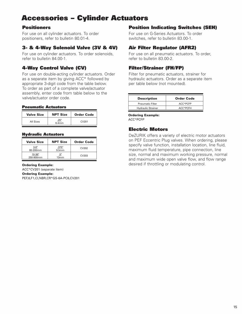
Accessories – Cylinder Actuators PositionersFor use on all cylinder actuators. To order positioners, refer to bulletin 80.01-4.
3- & 4-Way Solenoid Valve (3V & 4V)For use on cylinder actuators. To order solenoids, refer to bulletin 84.00-1.
4-Way Control Valve (CV)For use on double-acting cylinder actuators. Order as a separate item by giving ACC* followed by appropriate 3-digit code from the table below. To order as part of a complete valve/actuator assembly, enter code from table below to the valve/actuator order code.
Position Indicating Switches (SEH)For use on G-Series Actuators. To order switches, refer to bulletin 83.00-1.
Air Filter Regulator (AFR2)For use on all pneumatic actuators. To order, refer to bulletin 83.00-2.
Filter/Strainer (FH/FP)Filter for pneumatic actuators, strainer for hydraulic actuators. Order as a separate item per table below (not mounted).
Pneumatic Filter ACC*PCFP
Hydraulic Strainer ACC*PCFH
Description Order Code
Ordering Example: ACC*CV201 (separate item)Ordering Example: PEF,6,F1,CI,NBR,CR*GS-6A-PC6,CV201
Valve Size NPT Size Order Code
3-8" .375" 80-200mm 9.5mm
10-36" .5" 250-900mm 13mm
CV202
CV203
Hydraulic Actuators
All Sizes
.25" CV201 6.4mm
Valve Size NPT Size Order Code
Pneumatic Actuators
Electric MotorsDeZURIK offers a variety of electric motor actuators on PEF Eccentric Plug valves. When ordering, please specify valve function, installation location, line fluid, maximum fluid temperature, pipe connection, line size, normal and maximum working pressure, normal and maximum wide open valve flow, and flow range desired if throttling or modulating control.
Ordering Example: ACC*PCFP

Nut Actuated Valves (NT)3-8" (80-200mm)
3" 0.83 2.50 8.00 11.50 3.56 6.00 80mm 21 63 203 292 90 152
4" 1.02 2.50 9.00 14.25 7.50 100mm 26 63 229 362 191
5 & 6" 1.04 2.50 10.50 15.75 125 & 150mm 26 63 267 400
8" 1.23 2.50 11.50 17.38 7.65 11.75 200mm 31 63 292 441 194 298
10" 1.30 2.50 13.00 19.38 9.19 14.25 250mm 33 63 330 492 233 362
12" 1.36 2.50 14.00 20.75 11.53 17.00 300mm 35 63 355 527 293 432
14" 1.50 3.50 17.00 24.50 12.06 18.75 350mm 38 89 431 622 306 476
16" 1.55 3.50 17.75 27.25 14.13 21.25 400mm 39 89 450 692 359 540
18" 1.68 3.50 21.50 29.25 15.57 22.75 450mm 43 89 546 743 395 578
20" 1.76 3.50 23.50 31.00 16.81 25.00 500mm 45 89 596 787 427 635
24" 2.06 3.50 42.00 42.00 19.31 29.50 600mm 52 89 1067 1067 490 749
30" 2.53 4.00 51.00 51.00 21.75 36.00 750mm 64 102 1295 1524 552 914
36" 2.78 4.00 60.00 60.00 26.38 42.75 900mm 71 102 1524 1524 670 1086
5" (125mm)
8.50216
9.50241
6" (150mm)
Mechanical Joint
Mechanical Joint
A BValveSize Flanged
FlangedC D
(Flanged)CI
3" 9.38 80mm 203
4" 9.88 100mm 219
5 & 6" 12.31 125 & 150mm 313
8" 15.56 200mm 395
ValveSize K
InchMillimeter
InchMillimeter
D (Diameter of Bolt Circle)
Dimensions
Basic ValveCI=Cast Iron
A
Seat End of Valve
K
C
B
C
K
BB
C
K
A
Note: All dimensions are subject to change without notice. Request certified drawings for use in preparing piping layout.
4.43113
5.79147
16

17
180∞
SEAT END
OF VALVE
SEAT END
OF VALVE
180∞
270∞
90∞
STANDARD POSITION
ACTUATOR MOUNTING POSITIONS
OF VALVESEAT END
90∞
270∞
180∞
STANDARD POSITION
ACTUATOR MOUNTING POSITIONSACTUATOR MOUNTING POSITIONS
STANDARD POSITION
K
L
S
"R" DIA
237
9.33
178
7.00
95
3.75
K
"R" DIA
L
11.81
300
"R" DIA
97
3.81
K
L
S
SHU
T
OPEN
SEAT END
OF VALVE
GS-12AGS-6A
GS-6A-HD_ & GS-12A-HD_HANDWHEEL 3-20" (80-500mm) HANDWHEEL 16-30" (400-750mm)
MG-MJ50-HD_HANDWHEEL 30-36" (750-900mm)MG-ML60-HD_
Dimensions
SEAT ENDOF VALVE
SEAT END
OF VALVE
OF VALVE
SEAT END
SHUT
SHUT
OPE
N
OPE
N
SHUT
SHUT
OPE
N

STANDARD POSITIONACTUATOR MOUNTING POSITIONSSTANDARD POSITION
ACTUATOR MOUNTING POSITIONS
270∞
180∞
90∞
SEAT END
OF VALVE
180∞
270∞
STANDARD POSITION
ACTUATOR MOUNTING POSITIONS
OF VALVE
SEAT END
90∞
90∞
270∞
180∞
SEAT ENDOF VALVE
178
7.00
95
3.7597
3.81
"R" DIA
K
L
S
"R" DIA
237
9.33
K
L
S
"R" DIA
K
L
S
GS-12AGS-6A
GS-6A-CW_ & GS-12A-CW_CHAINWHEEL 3-20" (80-500mm) CHAINWHEEL 16-30" (400-750mm)
MG-MJ50-CW_CHAINWHEEL 30-36" (750-900mm)MG-ML60-CW_
Dimensions
SEAT END
OF VALVE
OF VALVE
SEAT END
OF VALVESEAT END
18

STANDARD POSITION
ACTUATOR MOUNTING POSITIONS
180∞
ACTUATOR MOUNTING POSITIONSSTANDARD POSITION
270∞SEAT ENDOF VALVE
90∞
ACTUATOR MOUNTING POSITIONS
STANDARD POSITION
270∞
180∞
SEAT END
90∞
OF VALVE 270∞
180∞
SEAT END
OF VALVE
90∞
S
SQUARE51
2.00
2.00
51SQUARE
S
S
2.00SQUARE
51
OPEN
SHU
T
OPE
N
SHUT
OPE
N
SHUT
GS-6A-N_ & GS-12A-N_NUT 3-20" (80-500mm) NUT 16-30" (400-750mm)
MG-MJ50-N_NUT 30-36" (750-900mm)MG-ML60-N_
Dimensions
SEAT ENDOF VALVE
OF VALVE
SEAT END SEAT END
OF VALVE
19
CWActuator
CodeK L R SValve
Size HD HD CW HD CW HD CW
20
5 & 6"125 & 150mm
8"200mm
10"250mm
12"300mm
14"350mm
4"100mm
3"80mm
16"400mm
GS-6A-HD8 (N)
GS-6A-CW8
GS-6A-HD8 (N)
GS-6A-CW8
GS-6A-HD8 (N)
GS-6A-CW8
GS-6A-HD8 (N)
GS-6A-CW8
GS-6A-HD12
GS-6A-CW12
GS-6A-HD8 (N)
GS-6A-CW8
GS-6A-HD12
GS-6A-CW12
GS-12A-HD12 (N)
GS-12A-CW12
GS-12A-HD16
GS-12A-CW20
GS-6A-HD12 (N)
GS-6A-CW12
GS-12A-HD12 (N)
GS-12A-CW12
GS-12A-HD16
GS-12A-HD20
GS-12A-CW20
GS-12A-HD12 (N)
GS-12A-CW12
GS-12A-HD16
GS-12A-HD20
GS-12A-CW20
GS-12A-HD24
GS-12A-CW24
GS-12A-HD16 (N)
GS-12A-HD20
GS-12A-CW20
GS-12A-HD24
GS-12A-CW24
MG-MJ50-HD12(N)
MG-MJ50-CW12
8.00 203
8.00 203
8.62 219
8.62 219
9.75 248
9.75 248
12.09 307
12.09 307
12.09 307
12.09 307
13.50 343
13.50 343
13.50 343
13.50 343
14.88 378
14.88 378
14.88 378
14.88 378
15.56 395
15.56 395
16.94 430
16.94 430
16.94 430
16.94 430
16.94 430
18.25 464
18.25 464
18.25 464
18.25 464
18.25 464
18.25 464
18.25 464
19.69 500
19.69 500
19.69 500
19.69 500
19.69 500
19.56 497
19.56 497
10.69 272
10.69 272
11.31 287
11.31 287
12.44 316
12.44 316
14.78 375
14.78 375
14.78 375
14.78 375
16.19 411
16.19 411
16.19 411
16.19 411
17.62 500
17.62 500
17.62 500
17.62 500
18.25 464
18.25 464
19.69 500
19.69 500
19.69 500
19.69 500
19.69 500
21.00 533
21.00 533
21.00 533
21.00 533
21.00 533
21.00 533
21.00 533
22.44 570
22.44 570
22.44 570
22.44 570
22.44 570
23.08 586
23.08 586
8.00 203
8.00 203
8.00 203
8.00 203
8.00 203
8.00 203
8.00 203
8.00 203
12.00 305
12.00 305
8.00 203
8.00 203
12.00 305
12.00 305
12.00 305
12.00 305
12.00 305
12.00 305
12.00 305
12.00 305
20.00 508
20.00 508
12.00 305
12.00 305
20.00 508
20.00 508
24.00 610
24.00 610
20.00 508
20.00 508
24.00 610
24.00 610
12.00 305
12.00 305
2" Nut (N)11.81 300
—
11.81 300
—
11.81 300
—
11.81 300
—
11.81 300
—
11.81 300
—
11.81 300
—
15.12 384
—
15.48 393
—
11.81 300
—
15.12 384
—
15.48 393
15.48 393
—
18.12 460
—
18.50 470
18.50 470
—
22.19 564
—
18.50 470
18.50 470
—
22.19 564
—
16.69 424
—
—
11.75 298
—
11.75 298
—
11.75 298
—
11.75 298
—
11.75 298
—
11.75 298
—
11.75 298
—
14.38 365
—
14.38 365
—
11.75 298
—
14.38 365
—
—
14.38 365
—
17.38 441
—
—
17.38 441
—
17.38 441
—
—
17.38 441
—
17.38 441
—
16.31 414
15.25 387
—
15.25 387
—
15.25 387
—
15.25 387
—
—
—
15.25 387
—
—
—
16.69 424
—
16.69 424
—
15.25 387
—
16.69 424
—
—
—
—
19.69 500
—
—
—
—
—
—
19.69 500
—
—
—
—
19.81 563
—
16.00 406
—
— 20.00 508
16.00 406
—
16.00 406
—
16.00 406
—
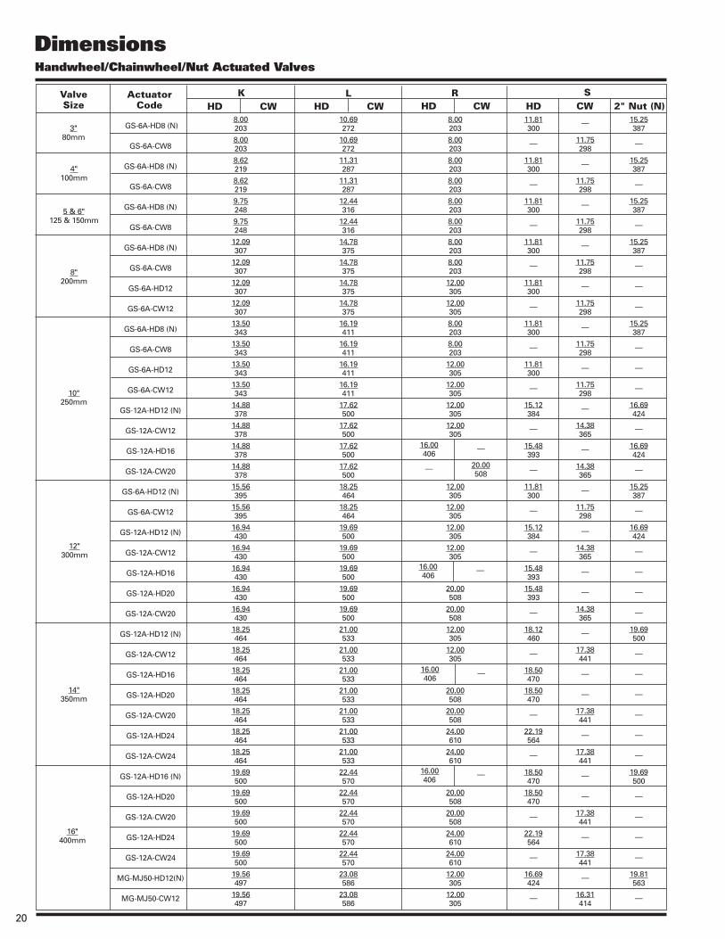
Dimensions Handwheel/Chainwheel/Nut Actuated Valves

Dimensions
21
Handwheel/Chainwheel/Nut Actuated Valves (continued)
CWActuator
CodeK L R SValve
Size HD HD CW HD CW HD CW
24"600mm
30"750mm
36"900mm
20"500mm
18"450mm
GS-12A-HD20 (N)
GS-12A-CW20
GS-12A-HD24
GS-12A-CW24
GS-12A-HD30
GS-12A-CW30
MG-MJ50-HD20 (N)
MG-MJ50-CW20
MG-MJ50-HD24
MG-MJ50-CW24
GS-12A-HD24 (N)
GS-12A-CW24
GS-12A-HD30
GS-12A-CW30
MG-MJ50-HD24 (N)
MG-MJ50-CW24
MG-MJ50-HD12 (N)
MG-MJ50-CW12
MG-MJ50-HD24
MG-MJ50-CW24
MG-MJ50-HD30
MG-MJ50-CW30
MG-MJ50-HD24 (N)
MG-MJ50-CW24
MG-MJ50-HD30
MG-MJ50-CW30
MG-ML60-HD24 (N)
MG-ML60-CW24
MG-ML60-HD24 (N)
MG-ML60-CW24
MG-ML60-HD30
MG-ML60-CW30
20.94 532
20.94 532
20.94 532
20.94 532
20.94 532
20.94 532
20.81 529
20.81 529
20.81 529
20.81 529
22.75 578
22.75 578
22.75 578
22.75 578
22.62 575
22.62 575
25.28 642
25.28 642
25.28 642
25.28 642
25.28 642
25.28 642
27.75 705
27.75 705
27.75 705
27.75 705
28.14 715
28.14 715
32.64 829
32.64 829
32.64 829
32.64 829
23.69 602
23.69 602
23.69 602
23.69 602
23.69 602
23.69 602
24.08 586
24.08 586
24.08 586
24.08 586
25.50 648
25.50 648
25.50 648
25.50 648
26.14 664
26.14 664
28.83 732
28.83 732
28.83 732
28.83 732
28.83 732
28.83 732
31.27 794
31.27 794
31.27 794
31.27 794
35.62 905
35.62 905
40.12 1019
40.12 1019
40.12 1019
40.12 1019
20.00 508
20.00 508
24.00 610
24.00 610
30.00 762
30.00 762
20.00 508
20.00 508
24.00 610
24.00 610
24.00 610
24.00 610
30.00 762
30.00 762
24.00 610
24.00 610
12.00 305
12.00 305
24.00 610
24.00 610
30.00 762
30.00 762
24.00 610
24.00 610
30.00 762
30.00 762
24.00 610
24.00 610
24.00 610
24.00 610
30.00 762
30.00 762
2" Nut (N)18.50 470
—
22.19 564
—
23.69 602
—
17.06 433
—
20.62 524
—
22.19 564
—
23.69 602
—
20.62 524
—
16.88 424
—
20.94 524
—
22.46 562
—
20.94 524
—
22.46 562
—
30.25 768
—
30.25 768
—
—
—
—
17.38 441
—
17.38 441
—
17.38 441
—
16.31 414
—
16.31 414
—
17.38 441
—
17.38 441
—
21.38 543
—
27.45 697
—
27.45 697
—
27.45 697
—
33.08 840
—
33.08 840
—
33.08 840
—
33.08 840
—
—
19.69 500
—
—
—
—
—
19.81 503
—
—
—
19.69 500
—
—
—
19.81 503
—
19.81 503
—
—
—
—
—
19.81 503
—
—
—
23.25 591
—
23.25 591
—
—
—
InchMillimeter
Note: All dimensions are subject to change without notice. Request certified drawings for use in preparing piping layout.

Dimensions Cylinder Actuated Valves
Actuator Code
K L M N R (NPT) PValveSize
12"300mm
14"350mm
16"400mm
8"200mm
3"80mm
GS-6A-PC4
GS-6A-PC6
GS-6A-PC4
GS-6A-PC6
GS-6A-PC4
GS-6A-PC6
GS-6A-PC8
GS-6A-PC6
GS-6A-PC8
GS-12A-PC6
GS-12A-PC8
GS-6A-PC6
GS-6A-PC8
GS-12A-PC6
GS-12A-PC8
GS-6A-PC6
GS-6A-PC8
GS-12A-PC6
GS-12A-PC8
GS-12A-PC10
GS-12A-PC6
GS-12A-PC8
GS-12A-PC10
GS-12A-PC6
GS-12A-PC8
GS-12A-PC10
GS-12A-PC8
GS-12A-PC10
GS-12A-PC10
4"100mm
5 & 6"125 & 150mm
10"250mm
18"450mm
20"500mm
8.00 203
8.00 203
8.62 219
8.62 219
9.75 248
9.75 248
9.75 248
12.09 307
12.09 307
12.78 325
12.78 325
13.50 343
13.50 343
14.19 360
14.19 360
15.56 395
15.56 395
16.25 413
16.25 413
16.25 413
17.56 446
17.56 446
17.56 446
19.00 483
19.00 483
19.00 483
20.25 514
20.25 514
22.06 560
10.88 276
10.88 276
11.50 292
11.50 292
12.62 321
12.62 321
12.62 321
14.97 380
14.97 380
16.41 417
16.41 417
16.38 416
16.38 416
17.81 452
17.81 452
18.44 468
18.44 468
19.88 505
19.88 505
19.88 505
21.19 538
21.19 538
21.19 538
22.62 575
22.62 575
22.62 575
23.88 607
23.88 607
25.69 653
18.88 480
19.12 486
18.88 480
19.12 486
18.88 480
19.12 486
19.38 492
19.12 486
19.38 492
30.56 776
30.88 784
19.12 486
19.38 492
30.56 776
30.88 784
19.12 486
19.38 492
30.56 776
30.88 784
31.00 787
30.56 776
30.88 784
31.00 787
30.56 776
30.88 784
31.00 787
30.88 784
31.00 787
31.00 787
2.19 56
3.19 81
2.19 56
3.19 81
2.19 56
3.19 81
4.56 116
3.19 81
4.56 116
3.25 83
4.25 108
3.19 81
4.56 116
3.25 83
4.25 108
3.19 81
4.56 116
3.25 83
4.25 108
5.25 133
3.25 83
4.25 108
5.25 133
3.25 83
4.25 108
5.25 133
4.25 108
5.25 133
5.25 133
1 4
1 2
1 4
1 2
1 4
1 2
1 2
1 2
1 2
1 2
1 2
1 2
1 2
1 2
1 2
1 2
1 2
1 2
1 2
3 4
1 2
1 2
3 4
1 2
1 2
3 4
1 2
3 4
3 4
11.35 288
11.35 288
11.35 288
11.35 288
11.35 288
11.35 288
11.35 288
11.35 288
11.35 288
17.50 445
17.50 445
11.35 288
11.35 288
17.50 445
17.50 445
11.35 288
11.35 288
17.50 445
17.50 445
17.50 445
17.50 445
17.50 445
17.50 445
17.50 445
17.50 445
17.50 445
17.50 445
17.50 445
17.50 445
InchMillimeter
Note: All dimensions are subject to change without notice. Request certified drawings for use in preparing piping layout.
22

23
Dimensions Cylinder (Spring Return) Actuated Valves
Actuator Code K L M N R (NPT) PValveSize
12"300mm
8"200mm
3"80mm
GS-6A-SC6
GS-6A-SC8
GS-6A-SC6
GS-6A-SC8
GS-6A-SC6
GS-6A-SC8
GS-6A-SC6
GS-6A-SC8
GS-12A-SC10
GS-12A-SC10
GS-12A-SC10
4"100mm
5 & 6"125 & 150mm
10"250mm
8.00 203
8.00 203
8.62 219
8.62 219
9.75 248
9.75 248
12.09 307
12.09 307
12.78 325
14.19 360
16.25 413
10.88 276
10.88 276
11.50 292
11.50 292
12.62 321
12.62 321
14.97 380
14.97 380
16.41 417
17.81 452
19.88 505
30.00 762
32.19 818
30.00 762
32.19 818
30.00 762
32.19 818
30.00 762
32.19 818
46.00 1168
46.00 1168
46.00 1168
3.19 81
4.56 116
3.19 81
4.56 116
3.19 81
4.56 116
3.19 81
4.56 116
5.25 133
5.25 133
5.25 133
1 2
1 2
1 2
1 2
1 2
1 2
1 2
1 2
3 4
3 4
3 4
11.35 298
11.35 298
11.35 298
11.35 298
11.35 298
11.35 298
11.35 298
11.35 298
17.50 445
17.50 445
17.50 445
InchMillimeter
Note: All dimensions are subject to change without notice. Request certified drawings for use in preparing piping layout.

Cylinder Actuated Valves
Dimensions
SHUT
OPEN
OPTIONAL MOUNTING POSITIONS.
FROM TOP OF VALVE. DOTTED LINES SHOW
ACTUATOR MOUNTING POSITIONS AS VIEWED
POSITION
SHOWN ON
90º
180º
270º
THIS DRAWING
STANDARD
OF VALVESEAT END
SEAT ENDOF VALVE
Seat End of Valve
GS-6A GS-12A 3.66 6.88 93 172
L
K
MP “R” NPT
Cylinder Actuated Valves (Spring Return)
GS-6A GS-12A 3.66 6.88 93 172
SHUT
OPEN
OF VALVESEAT END
SPRING TO OPEN POSITION.
DRAWING SHOWS ACTUATOR IN SPRING TO CLOSE
POSITION. DASHED LINES SHOW ACTUATOR IN
N
MP
“R” NPT
DeZURIK, Inc. reserves the right to incorporate our latest design and material changes without notice or obligation. Design features, materials of construction and dimensional data, as described in this bulletin, are provided for your information only
and should not be relied upon unless confirmed in writing by DeZURIK, Inc. Certified drawings are available upon request.
Printed in the U.S.A.
250 Riverside Ave. N. Sartell, Minnesota 56377 • Phone: 320-259-2000 • Fax: 320-259-2227
For information about our worldwide locations, approvals, certifications and local representative:Web Site: www.dezurik.com E-Mail: [email protected]
Sales and Service