Embed Size (px)
Citation preview
DEVICE FOR MEASURING THE E M I T T A N C E OF SOLIDS
AT ROOM TEMPERATURE
G. P. K a l u g i n , S. R. O s m o l o v s k i i , and V. A. C h i s t y a k o v UDC 681,2 : 536.3
Measurement of the emittance of solids at room temperature is of great scientific and practical importance, for instance, in space and vacuum technology, where it is necessary for calculating the thermal balance of objects under radiative heat exchange conditions, etc.
The devices available for this purpose [1, 2], while characterized by small measurement errors, have disad- vantages, such as low efficiency and the necessity for heating the specimens, which leads to errors in determining the surface temperature of heat insulation materials.
In practice, quick measurements of large batches of specimens are often performed at room temperature. The many devices available for this purpose, while characterized by low accuracy, secure the necessary speed, for in- stance, the domestically manufactured FM-63 instrument and the device described in [3].
In the FM-63 instrument, the radiation from the specimen is collected by means of a mirror system on the sur- face of a radiation receiver (bolometer), whose temperature is maintained by means of regulators at a level exceed- ing the specimen's temperature by 2-3 deg. A mirror chopper is used for chopping the radiation from the specimen. Two specimens with known emittance values are used for calibrating the receiving-recording system. The high cost of the instrument, its cumbersomeness, and the need for qualified operating personnel constitute its disadvantages.
The device described in [3] consists of a vacuum chamber with a window that transmits infrared radiation. In- side the chamber and adjacent to the window, there is a radiation receiver (thermoelement), whick is cooled as a result of heat transfer to a plate which is placed next to it. By means of a thermoelectric cooler, the plate tempera-
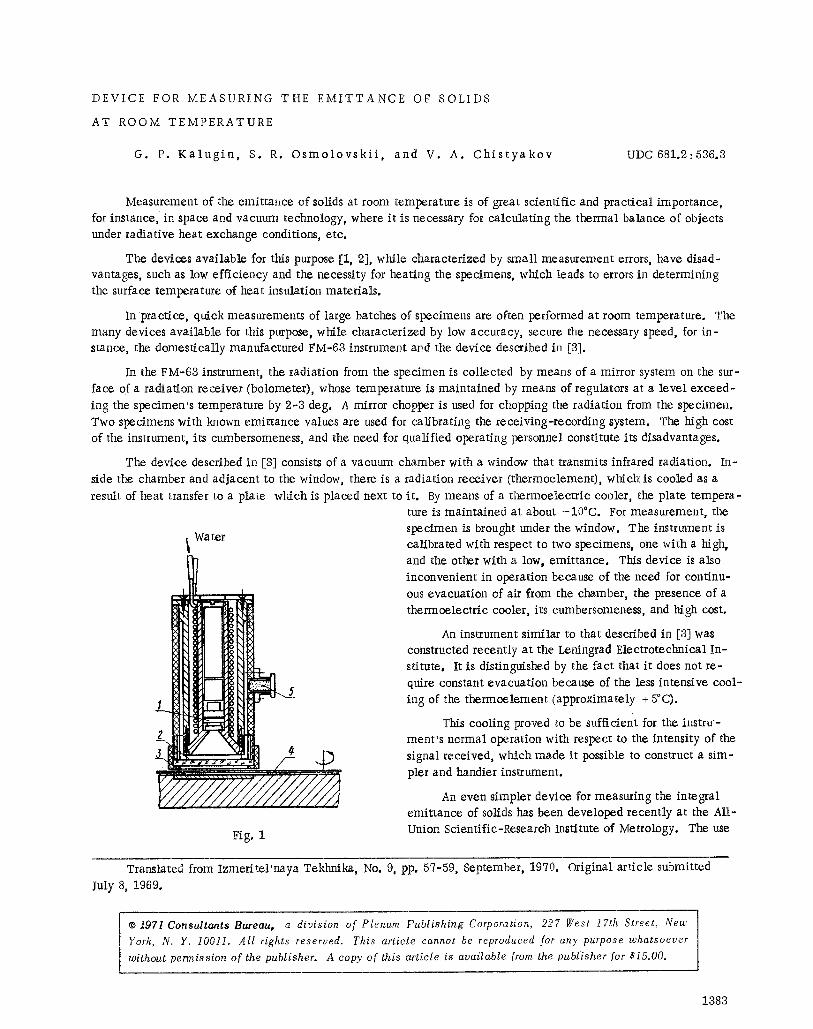
i Water
5
Fig. 1
to.re is maintained at about -10~ For measurement, the specimen is brought under the window. The instrm-nent is calibrated with respect to two specimens, one with a high, and the other with a low, emittance. This device is also inconvenient in operation because of the need for continu- ous evacuation of air from the chamber, the presence of a thermoelectric cooler, its cumbersomeness, and high cost.
An instrument similar to that described in [3] was constructed recently at the Leningrad Electrotechnical In- stitute. It is distinguished by the fact that it does not re- quire constant evacuation because of the less intensive cool- ing of the thermoelement (approximately + 5~
This cooling proved to be sufficient for the instru - ment's normal operation with respect to the intensity of the signal received, which made it possible to construct a sim- pler and handier instrument.
An even simpler device for measuring the integral emittance of solids has been developed recently at the All- Union Scientific-Research Institute of Metrology. The use
Translated ffom!zmeritel 'naya Tekhnika, No. 9, pp. 57-59, September, 1970. Original article submitted
July 8, 1969.
�9 197l Consultants Bureau, a division of Plenum Publishing Corporation, 227 [Vest 17th Street, New
York~ N. Y. 10011. All rights reserved. This article cannot be reproduced for any purpose whatsoever
[ without permission of the publisher. A copy of this article is available from the publisher [or $15.00.
1383
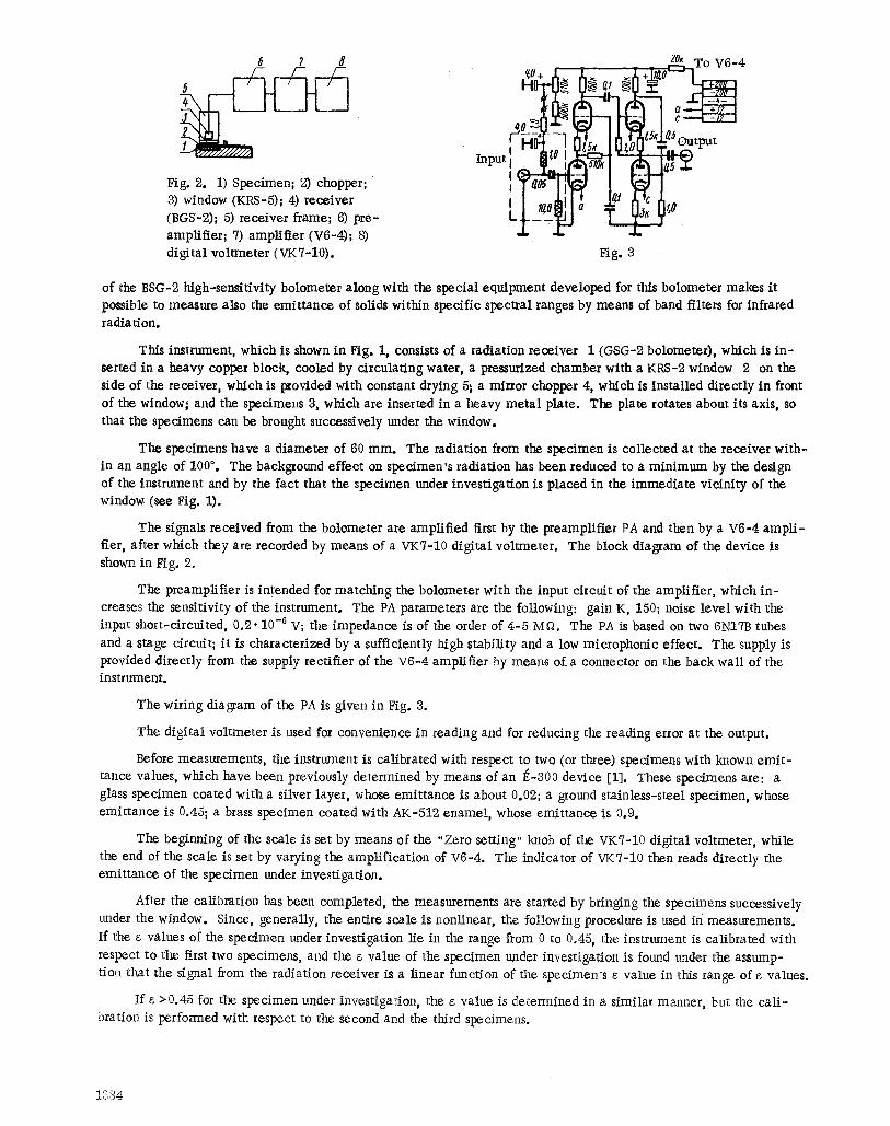
6 7 8
Fig. 2. 1) Specimen; 2) chopper; 3) window (KRS-5); 4) receiver (BGS-2); 5) receiver frame; 6) pre- amplifier; 7) amplifier (V6-4); 8) digital voltmeter (VKT-10).
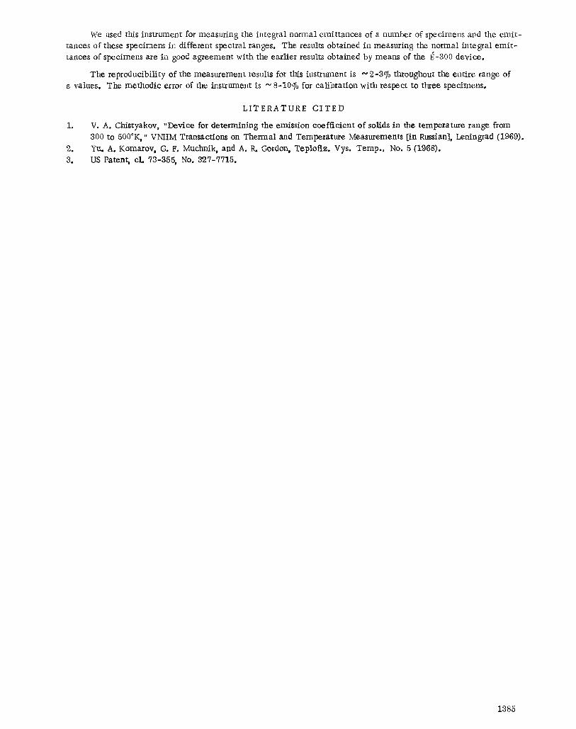
Input l I i 'LI a llW I
Fig. 3
20~ To V6-4
~ 5~:~ 5 Output
of the BSG-2 high-sensitivity bolometer along with the special equipment developed for this bolometer makes it possible to measure also the emittance of solids within specific spectral ranges by means of band filters for infrared radiation.
This instrument, which is shown in Fig. 1, consists of a radiation receiver I (GSG-2 bolometer), which is in- serted in a heavy copper block, cooled by circulating water, a pressurized chamber with a KRS-2 window 2 on the side of the receiver, which is provided with constant drying 5~ a mirror chopper 4, which is installed directly in front of the window~ and the specimens 3, which are inserted in a heavy metal plate. The plate rotates about its axis, so that the specimens can be brought successively under the window.
The specimens have a diameter of 60 ram. The radiation from the specimen is collected at the receiver with- in an angle of 100 ~ The baekground effect on specimen's radiation has been reduced to a minimum by the design of the instrument and by the fact that the specimen under investigation is placed in the immediate vicinity of the window (see Fig. I).
The signals received from the bolometer are amplified first by the preamplifier PA and then by a V6-4 ampli- fier, after which they are recorded by means of a VKT-10 digital voltmeter. The block diagram of the device is shown in Fig. 2.
The preamplifier is intended for matching the bolometer with the input circuit of the amplifier, which in- creases the sensitivity of the instrument. The PA parameters are the following: gain K, 150; noise level with the input short-circuited, 0.2.10 -6 V; the impedance is of the order of 4-5 Mf~. The PA is based on two 6NITB tubes
and a stage circuit; it is characterized by a sufficiently high stability and a low microphonic effect. The supply is provided directly from the supply rectifier of the V6-4 amplifier by means of a connector on the back wall of the instrument.
The wiring diagram of the PA is given in Fig. 3.
The digital voltmeter is used for convenience in reading and for reducing the reading error at the output.
Before measurements, the instrument is calibrated with respect to two (or three) specimens with known emit - tance values, which have been previously determined by means of an ~-300 device [1]. These specimens are: a glass specimen coated with a silver layer, whose emittance is about 0.02; a ground stainless-steel specimen, whose emittance is 0.45; a brass specimen coated with AK-512 enamel, whose emittance is 0.9.
The beginning of the scale is set by means of the "Zero setting" knob of the VK7-10 digital voltmeter, while the end of the scale is set by varying the amplification of V6-4. The indicator of VK7-10 then reads directly the emittance of the specimen under investigation.
After the calibration has been completed, the measurements are started by bringing the specimens successively under the window. Since, generally, the entire scale is nonlinear, the following procedure is used in measurements. If the s values of the specimen under investigation lie in the range from 0 to 0.45, the instrument is calibrated with respect to the first two specimens, and the s value of the specimen under investigation is found under the assump- tion that the signal from the radiation receiver is a linear function of the speeimen's s value in this range of s values.
If s >0.45 for the specimen under investigation, the s value is determined in a similar manner, but the cal i- bration is performed with respect to the second and the third specimens.
ff384
We used this instrument for measuring the integral normal emittances of a number of specimens and the emit- tanoes of these specimens in different spectral ranges, The results obtained in measuring the normal integral emit- tanees of specimens are in good agreement with the earlier results obtained by means of the ~-300 device.
The reproducibility of the measurement results for this instrument is ~ 2-3% throughout the entire range of s values. The methodic error of the instrument is ~ 8-10% for calibration with respect to three specimens.
io
2. 8.
LITERATURE C I T E D
V. A. Chistyakov, "Device for determining the emission coefficient of solids in the temperature range from 300 to 500~ VNIIM Transactions on Thermal and Temperature Measurements [in Russian], Leningrad (1969). Yu. A. Komarov, G. F. Muchnik, and A. tL Gordon, Teplofiz. Vys. Temp., No. 5 (1968). US Patent, el. 73-355, No. 327-7715.
1885