Embed Size (px)
Citation preview

Caving 2018 – Y Potvin and J Jakubec (eds) © 2018 Australian Centre for Geomechanics, Perth, ISBN 978-0-9924810-9-4
Caving 2018, Vancouver, Canada
Development planning for the Oyu Tolgoi panel cave mine
K Crook Rio Tinto, Australia
F Prince Rio Tinto, Australia
Abstract
Oyu Tolgoi is a large panel cave mine currently under construction in the Gobi Desert of Mongolia. Due to the overall length of the Hugo North orebody at Oyu Tolgoi stretching almost 2 km, the Lift 1 production area has been split into three production panels. These panels in turn have been sub-blocked into smaller, more manageable segments for development.
Panel 0 (P0) was broken into P0A and P0B, southern and northern halves respectively, for the sequencing of development activities. The overall sequence philosophy for the panel is to fully develop these sub-panels and hand them over for production activities. The isolation of activities is seen as a risk reduction because it reduces the interactions between the undercutting and development activities.
This paper will discuss the strategies followed for development of such a large-scale underground production panel, including the development sequence, undercut initiation, and the challenges of executing a project in a remote area of the world.
Keywords: large-scale, development, production panel, remote location
1 Introduction
Oyu Tolgoi is a large copper porphyry deposit located in the Omnigovi province of Mongolia, situated approximately 500 km south of the capital, Ulaanbaatar, and 80 km north of the border with China (Figure 1). There is an open pit and concentrator that have been in operation since 2012. The underground project initiated with a development shaft in 2006, and with early development works running until 2013, resulting in approximately 16 km of development; one shaft fully equipped and the second at 80% depth. In 2016, the underground project was started after a brief hiatus.
Figure 1 Oyu Tolgoi location in Mongolia, relative to Ulaanbaatar and China
https://papers.acg.uwa.edu.au/p/1815_30_Crook/
Development planning for the Oyu Tolgoi panel cave mine K Crook and F Prince
Caving 2018, Vancouver, Canada
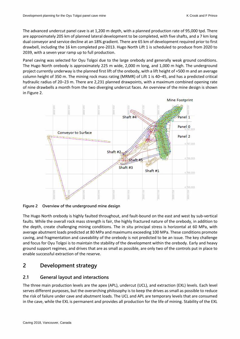
The advanced undercut panel cave is at 1,200 m depth, with a planned production rate of 95,000 tpd. There are approximately 205 km of planned lateral development to be completed, with five shafts, and a 7 km long dual conveyor and service decline at an 18% gradient. There are 65 km of development required prior to first drawbell, including the 16 km completed pre-2013. Hugo North Lift 1 is scheduled to produce from 2020 to 2039, with a seven year ramp up to full production.
Panel caving was selected for Oyu Tolgoi due to the large orebody and generally weak ground conditions. The Hugo North orebody is approximately 225 m wide, 2,000 m long, and 1,000 m high. The underground project currently underway is the planned first lift of the orebody, with a lift height of +500 m and an average column height of 350 m. The mining rock mass rating (MRMR) of Lift 1 is 40–45, and has a predicted critical hydraulic radius of 20–23 m. There are 2,231 planned drawpoints, with a maximum combined opening rate of nine drawbells a month from the two diverging undercut faces. An overview of the mine design is shown in Figure 2.
Figure 2 Overview of the underground mine design
The Hugo North orebody is highly faulted throughout, and fault-bound on the east and west by sub-vertical faults. While the overall rock mass strength is fair, the highly fractured nature of the orebody, in addition to the depth, create challenging mining conditions. The in situ principal stress is horizontal at 60 MPa, with average abutment loads predicted at 80 MPa and maximums exceeding 100 MPa. These conditions promote caving, and fragmentation and caveability of the orebody is not predicted to be an issue. The key challenge and focus for Oyu Tolgoi is to maintain the stability of the development within the orebody. Early and heavy ground support regimes, and drives that are as small as possible, are only two of the controls put in place to enable successful extraction of the reserve.
2 Development strategy
2.1 General layout and interactions
The three main production levels are the apex (APL), undercut (UCL), and extraction (EXL) levels. Each level serves different purposes, but the overarching philosophy is to keep the drives as small as possible to reduce the risk of failure under cave and abutment loads. The UCL and APL are temporary levels that are consumed in the cave, while the EXL is permanent and provides all production for the life of mining. Stability of the EXL
Mine planning
Caving 2018, Vancouver, Canada
is paramount, and everything that can be done to protect the level from the cave stresses will be undertaken, to provide more value and operability for the mine.
The rim drives on all levels lie on the east and west of the footprint and are generally 5 m wide × 5.5 m high to accommodate the larger delivery and support equipment. The size also supports truck loading as near as possible to the footprint development. The temporary drives that crosscut the orebody have been deemed ‘internal rim drives’. The internal rim drive sizing is 4.6 m wide × 5.1 m high to accommodate medium and small equipment, and two biduct vent bags to feed the drill and extraction drive development. The internal rim drives are temporary and will be consumed in the cave as it progresses.
All permanent cut-outs are positioned on the rim drives to keep them accessible but away from the highest cave stresses. This is especially true for fixed infrastructure and material laydowns that are required for a significant period of time as the drawbells are constructed.
2.1.1 Apex level
The purpose of the APL is to:
Maximise the chance of undercut breakage across the top of the major apex pillar. Apex tunnels are developed along the peak of the major apex, creating a void and ensuring breakage at the apex of the pillar. The toes of longhole rings drilled from the UCL break into, or adjacent to, the apex drives.
Provide a platform for inspecting the breakage at the toes of the undercut blasts, by line-of-sight and by using 3D laser scanning, to ensure any remnant pillars are identified early and a plan is implemented to remove them.
Provide an additional platform for drilling and removing pillars.
Improve management and control of swell tonnage removal. 3D laser scanning can occur at the apex level; the requirement to muck the brow open on the undercut to inspect for void and breakage is minimised, reducing exposure of personnel to safety hazards around open brows along with improving control of swell tonnage removal.
The APL development is mostly temporary and gets consumed into the cave as the undercut progresses.
Standard APL drives are 4 m wide × 4.2 m high excavated, matching the UCL drill drives, on 28 m spacing. The APL sits 17 m, floor-to-floor, above the UCL.
2.1.2 Undercut level
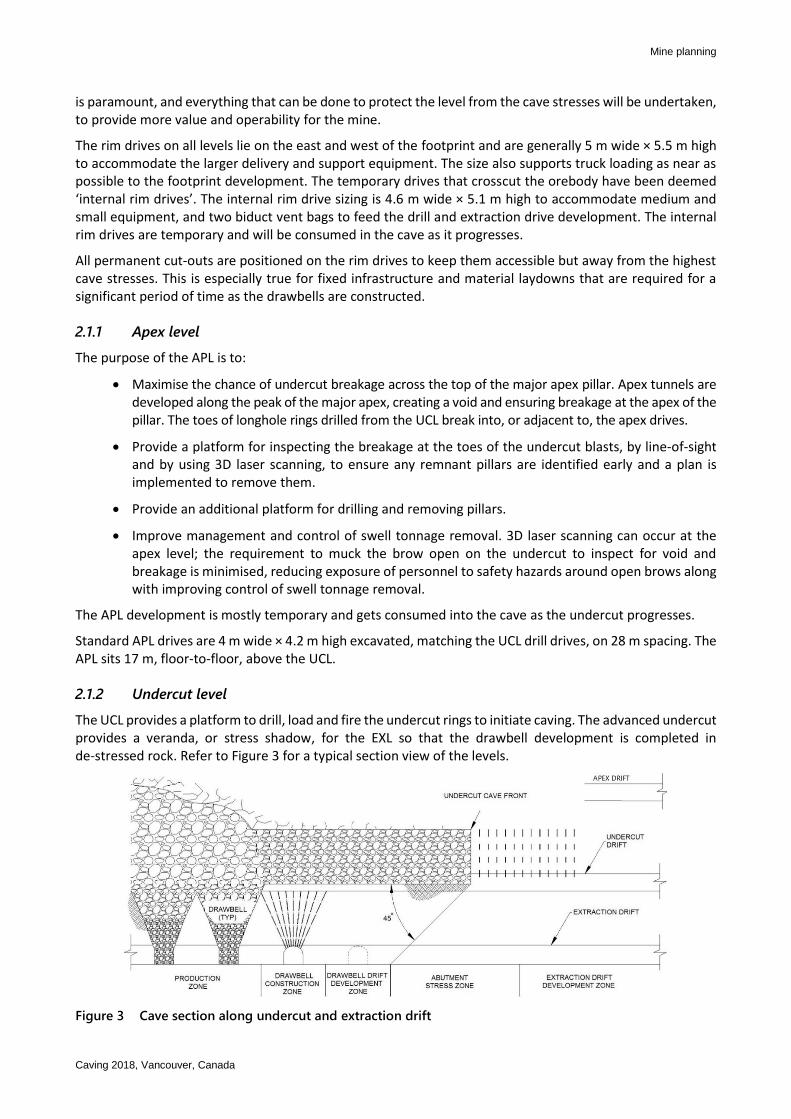
The UCL provides a platform to drill, load and fire the undercut rings to initiate caving. The advanced undercut provides a veranda, or stress shadow, for the EXL so that the drawbell development is completed in de-stressed rock. Refer to Figure 3 for a typical section view of the levels.
Figure 3 Cave section along undercut and extraction drift
Development planning for the Oyu Tolgoi panel cave mine K Crook and F Prince
Caving 2018, Vancouver, Canada
The firing of rings on the UCL is constant and moves at a rate of 7.5–10 m/month for the life of the mine. The minimum undercut advance rate of 7.5 m/month is required to dissipate the abutment loads and to minimise stress concentrations and damage to the UCL or EXL. The maximum undercut speed is dictated by the rate of drawbell opening on the EXL, so that the veranda from the undercut face to the point of blasting bells below is in the order of 30–40 m, equating to a time from undercut passing to drawbell firing of approximately four months. Larger veranda distances/durations create higher stresses wrapping around the undercut front, increasing risk of undercut drive damage, and increase the risk of re-compaction of the undercut blasted material, increasing risk of transmitting stress and resulting in extraction level drive damage.
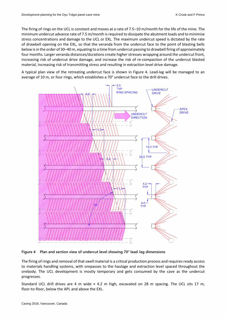
A typical plan view of the retreating undercut face is shown in Figure 4. Lead-lag will be managed to an average of 10 m, or four rings, which establishes a 70° undercut face to the drill drives.
Figure 4 Plan and section view of undercut level showing 70° lead-lag dimensions
The firing of rings and removal of that swell material is a critical production process and requires ready access to materials handling systems, with orepasses to the haulage and extraction level spaced throughout the orebody. The UCL development is mostly temporary and gets consumed by the cave as the undercut progresses.
Standard UCL drill drives are 4 m wide × 4.2 m high, excavated on 28 m spacing. The UCL sits 17 m, floor-to-floor, below the APL and above the EXL.
Mine planning
Caving 2018, Vancouver, Canada
An undercut face is typically 10 drives wide and additional apex and undercut level specifications are included in Table 1. Daily average performance indicators set for one caving face, for different undercut retreat rates, are illustrated in Table 2. Note that upside capacity will be in place to meet higher short-term demands to achieve the average rates.
Table 1 Apex and undercut level specifications
Sequence Advanced
Drive spacing (m) 28
Level spacing (m) 17
Drive size excavated (m) 4 wide × 4.2 high
Profile Big ‘W’ style
Undercut area (m2) 567,000
Drillhole ring spacing (m) 2.5
Drill metres per ring (m) 147
Ring dump angle 75o
Blasthole diameter (mm) 102
Lead/lag (m) 10
Tonnes per ring (60% swell) 767
Table 2 Daily average performance indicators for one caving face at two different undercut retreat rates
Activity @ 7.5 m/month/drive @ 10 m/month/drive
Rings/mo/drive 3 4
Rings blasted/day 1 1.3
Tonnes mucked/day 800 1,050
Longhole m drilled/day 150 200
Bells/mo equivalent (approx.) 4.7 6.3
2.1.3 Extraction level
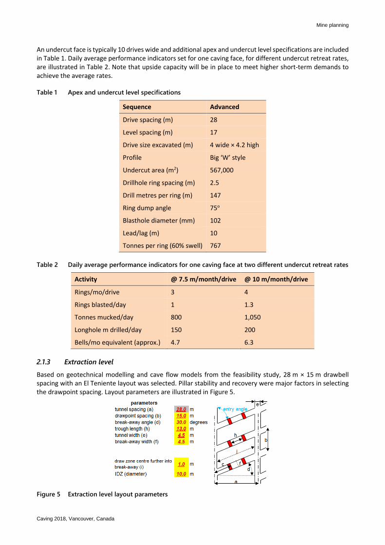
Based on geotechnical modelling and cave flow models from the feasibility study, 28 m × 15 m drawbell spacing with an El Teniente layout was selected. Pillar stability and recovery were major factors in selecting the drawpoint spacing. Layout parameters are illustrated in Figure 5.
Figure 5 Extraction level layout parameters
Development planning for the Oyu Tolgoi panel cave mine K Crook and F Prince
Caving 2018, Vancouver, Canada
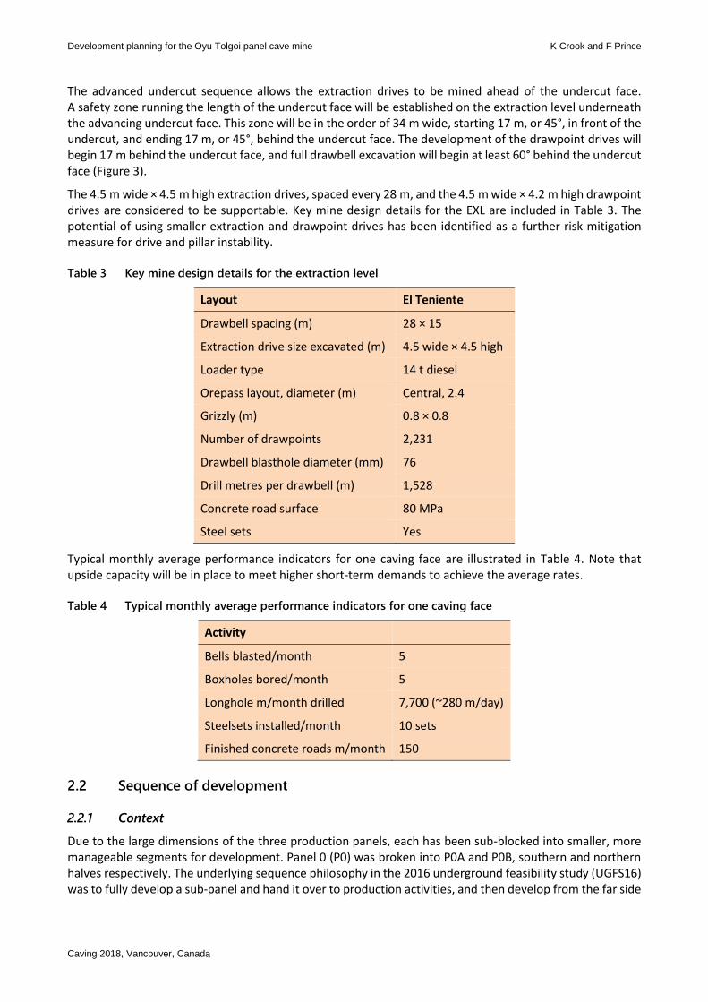
The advanced undercut sequence allows the extraction drives to be mined ahead of the undercut face. A safety zone running the length of the undercut face will be established on the extraction level underneath the advancing undercut face. This zone will be in the order of 34 m wide, starting 17 m, or 45°, in front of the undercut, and ending 17 m, or 45°, behind the undercut face. The development of the drawpoint drives will begin 17 m behind the undercut face, and full drawbell excavation will begin at least 60° behind the undercut face (Figure 3).
The 4.5 m wide × 4.5 m high extraction drives, spaced every 28 m, and the 4.5 m wide × 4.2 m high drawpoint drives are considered to be supportable. Key mine design details for the EXL are included in Table 3. The potential of using smaller extraction and drawpoint drives has been identified as a further risk mitigation measure for drive and pillar instability.
Table 3 Key mine design details for the extraction level
Layout El Teniente
Drawbell spacing (m) 28 × 15
Extraction drive size excavated (m) 4.5 wide × 4.5 high
Loader type 14 t diesel
Orepass layout, diameter (m) Central, 2.4
Grizzly (m) 0.8 × 0.8
Number of drawpoints 2,231
Drawbell blasthole diameter (mm) 76
Drill metres per drawbell (m) 1,528
Concrete road surface 80 MPa
Steel sets Yes
Typical monthly average performance indicators for one caving face are illustrated in Table 4. Note that upside capacity will be in place to meet higher short-term demands to achieve the average rates.
Table 4 Typical monthly average performance indicators for one caving face
Activity
Bells blasted/month 5
Boxholes bored/month 5
Longhole m/month drilled 7,700 (~280 m/day)
Steelsets installed/month 10 sets
Finished concrete roads m/month 150
2.2 Sequence of development
2.2.1 Context
Due to the large dimensions of the three production panels, each has been sub-blocked into smaller, more manageable segments for development. Panel 0 (P0) was broken into P0A and P0B, southern and northern halves respectively. The underlying sequence philosophy in the 2016 underground feasibility study (UGFS16) was to fully develop a sub-panel and hand it over to production activities, and then develop from the far side
Mine planning
Caving 2018, Vancouver, Canada
of the second panel and break into the production panel. The isolation of activities is seen as a risk reduction as it reduces the interactions between the production and development activities.
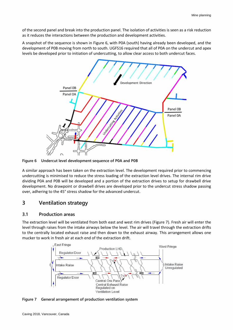
A snapshot of the sequence is shown in Figure 6, with P0A (south) having already been developed, and the development of P0B moving from north to south. UGFS16 required that all of P0A on the undercut and apex levels be developed prior to initiation of undercutting, to allow clear access to both undercut faces.
Figure 6 Undercut level development sequence of P0A and P0B
A similar approach has been taken on the extraction level. The development required prior to commencing undercutting is minimised to reduce the stress loading of the extraction level drives. The internal rim drive dividing P0A and P0B will be developed and a portion of the extraction drives to setup for drawbell drive development. No drawpoint or drawbell drives are developed prior to the undercut stress shadow passing over, adhering to the 45° stress shadow for the advanced undercut.
3 Ventilation strategy
3.1 Production areas
The extraction level will be ventilated from both east and west rim drives (Figure 7). Fresh air will enter the level through raises from the intake airways below the level. The air will travel through the extraction drifts to the centrally located exhaust raise and then down to the exhaust airway. This arrangement allows one mucker to work in fresh air at each end of the extraction drift.
Figure 7 General arrangement of production ventilation system
Development planning for the Oyu Tolgoi panel cave mine K Crook and F Prince
Caving 2018, Vancouver, Canada
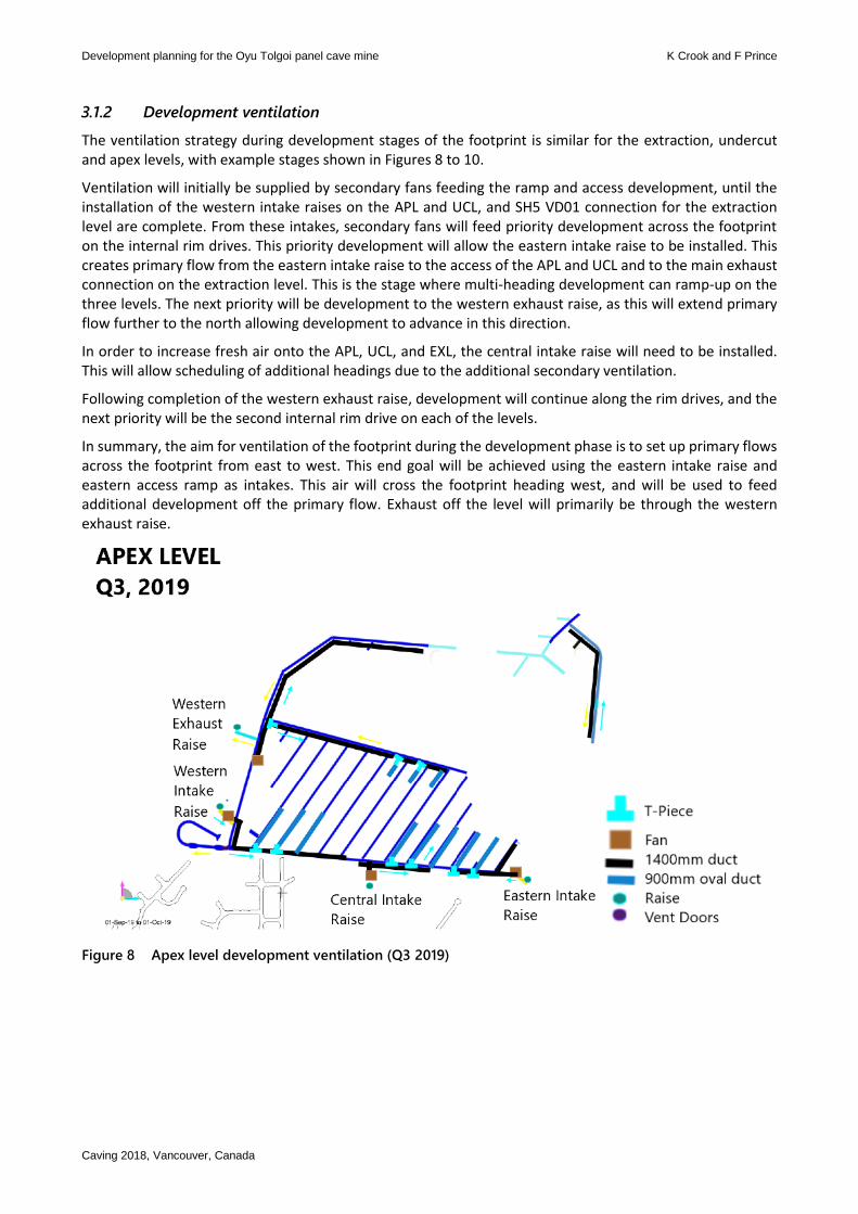
3.1.2 Development ventilation
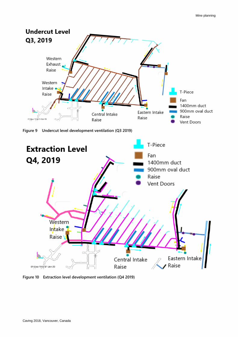
The ventilation strategy during development stages of the footprint is similar for the extraction, undercut and apex levels, with example stages shown in Figures 8 to 10.
Ventilation will initially be supplied by secondary fans feeding the ramp and access development, until the installation of the western intake raises on the APL and UCL, and SH5 VD01 connection for the extraction level are complete. From these intakes, secondary fans will feed priority development across the footprint on the internal rim drives. This priority development will allow the eastern intake raise to be installed. This creates primary flow from the eastern intake raise to the access of the APL and UCL and to the main exhaust connection on the extraction level. This is the stage where multi-heading development can ramp-up on the three levels. The next priority will be development to the western exhaust raise, as this will extend primary flow further to the north allowing development to advance in this direction.
In order to increase fresh air onto the APL, UCL, and EXL, the central intake raise will need to be installed. This will allow scheduling of additional headings due to the additional secondary ventilation.
Following completion of the western exhaust raise, development will continue along the rim drives, and the next priority will be the second internal rim drive on each of the levels.
In summary, the aim for ventilation of the footprint during the development phase is to set up primary flows across the footprint from east to west. This end goal will be achieved using the eastern intake raise and eastern access ramp as intakes. This air will cross the footprint heading west, and will be used to feed additional development off the primary flow. Exhaust off the level will primarily be through the western exhaust raise.
Figure 8 Apex level development ventilation (Q3 2019)
Mine planning
Caving 2018, Vancouver, Canada
Figure 9 Undercut level development ventilation (Q3 2019)
Figure 10 Extraction level development ventilation (Q4 2019)
Development planning for the Oyu Tolgoi panel cave mine K Crook and F Prince
Caving 2018, Vancouver, Canada
4 Waste/ore handling
4.1 Development
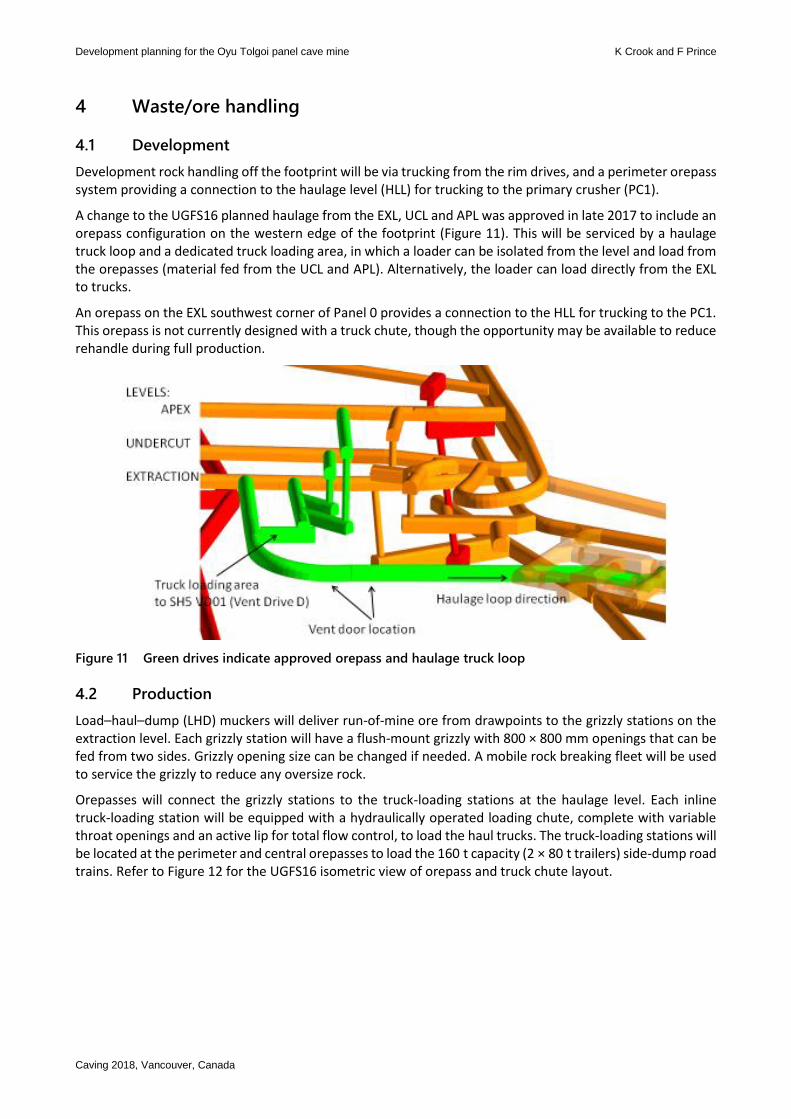
Development rock handling off the footprint will be via trucking from the rim drives, and a perimeter orepass system providing a connection to the haulage level (HLL) for trucking to the primary crusher (PC1).
A change to the UGFS16 planned haulage from the EXL, UCL and APL was approved in late 2017 to include an orepass configuration on the western edge of the footprint (Figure 11). This will be serviced by a haulage truck loop and a dedicated truck loading area, in which a loader can be isolated from the level and load from the orepasses (material fed from the UCL and APL). Alternatively, the loader can load directly from the EXL to trucks.
An orepass on the EXL southwest corner of Panel 0 provides a connection to the HLL for trucking to the PC1. This orepass is not currently designed with a truck chute, though the opportunity may be available to reduce rehandle during full production.
Figure 11 Green drives indicate approved orepass and haulage truck loop
4.2 Production
Load–haul–dump (LHD) muckers will deliver run-of-mine ore from drawpoints to the grizzly stations on the extraction level. Each grizzly station will have a flush-mount grizzly with 800 × 800 mm openings that can be fed from two sides. Grizzly opening size can be changed if needed. A mobile rock breaking fleet will be used to service the grizzly to reduce any oversize rock.
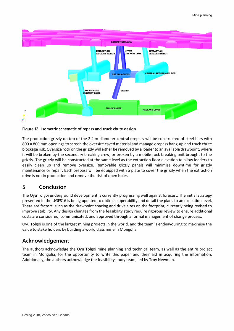
Orepasses will connect the grizzly stations to the truck-loading stations at the haulage level. Each inline truck-loading station will be equipped with a hydraulically operated loading chute, complete with variable throat openings and an active lip for total flow control, to load the haul trucks. The truck-loading stations will be located at the perimeter and central orepasses to load the 160 t capacity (2 × 80 t trailers) side-dump road trains. Refer to Figure 12 for the UGFS16 isometric view of orepass and truck chute layout.
Mine planning
Caving 2018, Vancouver, Canada
Figure 12 Isometric schematic of repass and truck chute design
The production grizzly on top of the 2.4 m diameter central orepass will be constructed of steel bars with 800 × 800 mm openings to screen the oversize caved material and manage orepass hang-up and truck chute blockage risk. Oversize rock on the grizzly will either be removed by a loader to an available drawpoint, where it will be broken by the secondary breaking crew, or broken by a mobile rock breaking unit brought to the grizzly. The grizzly will be constructed at the same level as the extraction floor elevation to allow loaders to easily clean up and remove oversize. Removable grizzly panels will minimise downtime for grizzly maintenance or repair. Each orepass will be equipped with a plate to cover the grizzly when the extraction drive is not in production and remove the risk of open holes.
5 Conclusion
The Oyu Tolgoi underground development is currently progressing well against forecast. The initial strategy presented in the UGFS16 is being updated to optimise operability and detail the plans to an execution level. There are factors, such as the drawpoint spacing and drive sizes on the footprint, currently being revised to improve stability. Any design changes from the feasibility study require rigorous review to ensure additional costs are considered, communicated, and approved through a formal management of change process.
Oyu Tolgoi is one of the largest mining projects in the world, and the team is endeavouring to maximise the value to stake holders by building a world class mine in Mongolia.
Acknowledgement
The authors acknowledge the Oyu Tolgoi mine planning and technical team, as well as the entire project team in Mongolia, for the opportunity to write this paper and their aid in acquiring the information. Additionally, the authors acknowledge the feasibility study team, led by Troy Newman.

Development planning for the Oyu Tolgoi panel cave mine K Crook and F Prince
Caving 2018, Vancouver, Canada


