Embed Size (px)
Citation preview

DEVELOPMENT OF SOIL STIFFNESS EVALUATION EQUIPMENT “ALFA-SYSTEM” USING ACCELERATION RESPONSE OF VIBRATORY ROLLER
Hiroshi Furuya1 and Tetsuo Fujiyama 2
1 Technical Research Institute, Obayashi Corporation, Tokyo, Japan
2 Technical Research Institute, Maeda Corporation, Tokyo, Japan
* Corresponding author ([email protected])
ABSTRACT: Recent years, new construction systems as AMG (automatic Machine Guidance) and AMC (Automatic
Machine Control) have been developed with the Global Positioning System (GPS) and made fit for practical use. Added to
this, an indirect measuring theory to control the compaction extent and elasticity, which uses the acceleration data of
compaction drum, has been researched and developed since 1998 in Japan, and has recently come to be applied to the real
construction sites. From such a background, the authors developed new equipment which is named “Alfa-system” for
quality control of soil compaction. The advantage of the system is as follows. Fill compaction levels can be real-timely
judged. Acceleration data of wheel vibration are consecutively measured, and these data are transmitted to the control room
for data processing. Then, the data are compared with the standard control values that are established beforehand by the test
executions. Examined data can be used for countermeasures, such as eliminating the under-compacted or inferior parts. And
this system provides more benefit, once using system in construction, both supervisor in the sight office and driver of the
compaction rollers can see 2-dimentional pictures of the compacted levels on the computer screens. And the data from Alfa-
system can be used for QC/QA. Moreover, in the future, the system can be improved to feed back to the quality control
immediately. This will improve the effectiveness and efficiency of compaction control.
Keywords: Construction Machinery, Construction Method, Compaction, QC/QA, Real-time Measurement, Intelligent
Compaction
1. INTRODUCTION
The reliability design method has long been adopted in
civil engineering work, for structures in particular. Placing
orders for structures specifying the performance has been a
common practice. Earth structures involve high design and
construction uncertainty attributable mainly to soils that are
used as material. Such structures have been designed using
a simplified model and their construction has been
controlled by specifying the method and through quality
control based on the testing of soil samples. For
construction control during embankment work, field
density measurement using radioactive gauges or by sand
replacement tests, or soil stiffness measurement through
plate loading tests is generally employed at present to
control the compaction of the fill in the field.
Measurements are, however, taken only discretely, so
effectively evaluating quality throughout the construction
surface is difficult. Studies have been made on a method of
determining the level of soil compaction by measuring the
acceleration of vibrating wheel of a vibratory roller during
construction using the tendency of acceleration response of
a vibratory roller to vary according to the level of soil
compaction. The method enables real-time evaluation of
compaction quality along the surface during construction,
so it will be much more effective than conventional
compaction control methods.
The method is also expected to provide sufficient
data for reliability design. North European countries have
been leading studies on the method1). Studies were started
in Japan around 19802). Various Roller Measured Value
(RMV) have been invented by different roller
manufacturers since the Compaction Meter Value (CMV)
S9-7
337
was developed (Thurner, 19801)). Those systems with
various formulae are listed in Table 1. There are
dimensionless RMVs values such as CMV and
Compaction Control Value 2) (CCV Sakai, 2005) while
other RMVs that measure stiffness in units of MN/m such
as ks (Andergg et al., 2004), or with the dimension of a
modulus in units of MN/m2 (Scherocman et al.3), 2006)
such as Alfa-System (advanced vibrating roller frequent
analyze system) of this paper, and Evib4) (Kloubert, 2006).
Applicable geological conditions have not yet been
identified and the accuracy of construction control has yet
to be fully verified. The method has therefore not been put
to practical use. The authors have been conducting a series
of researches for practical application of the method with
such a respect as the effects of conditions of geology and
vibratory roller5)-9). This paper outlines soil compaction
control equipment that the authors developed based on the
researches to effectively control the compaction of fill
materials. This document also makes a report on the results
of evaluation of the applicability of the equipment.
Table 1: Intelligent compaction systems with various
formulae
None
Yes(2&3D)
Yes
Yes(2&3D)
None
None
CAD
Compatibility
MN/m2YesEvibBomag
MN/m2YesAlfaObayashi-
Maeda
MN/mYesksAmmann
NoneYesCCVSakai
NoneYesCMVDynapac
NoneYesCMVCaterpillar
Measurement and Analyzing methodUnitAccel
erometer
IC system
Vendors
None
Yes(2&3D)
Yes
Yes(2&3D)
None
None
CAD
Compatibility
MN/m2YesEvibBomag
MN/m2YesAlfaObayashi-
Maeda
MN/mYesksAmmann
NoneYesCCVSakai
NoneYesCMVDynapac
NoneYesCMVCaterpillar
Measurement and Analyzing methodUnitAccel
erometer
IC system
Vendors
A
mmdfks tr cos
4 22
AA
CCMVGeodynamik 2
bmVga
WVPMDPg
sin
A
AlueBouncingVa 5.0
AA
CCMVGeodynamik 2
1005.0
35.225.15.0
AA
AAAAACCV
gmmFSS
SSFt i i
ii
)('
'
21
00
3
1
3
1
2
21
2
2
2
02
)(1
164.11024.032.01
)2(134
)1(2
gmmF
mfFt
BE
LF
ER
Bwhere s
VIB
2116
,
B
L
L
F
EZ t
VIBa ln8864.1
21 2
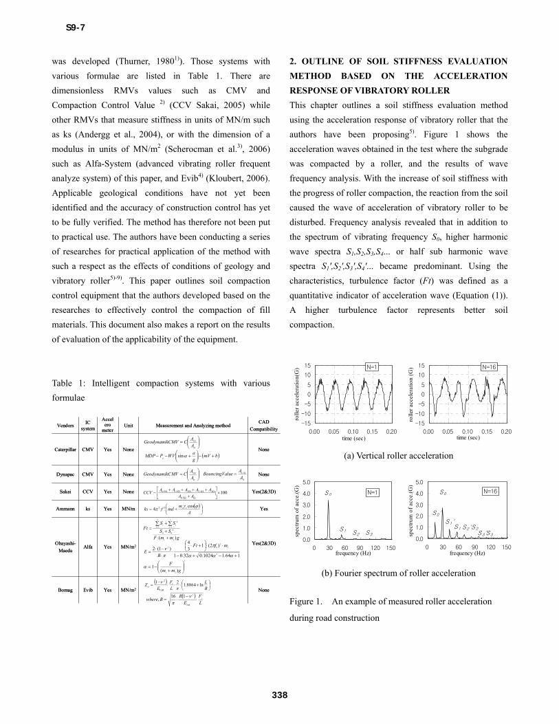
2. OUTLINE OF SOIL STIFFNESS EVALUATION
METHOD BASED ON THE ACCELERATION
RESPONSE OF VIBRATORY ROLLER
This chapter outlines a soil stiffness evaluation method
using the acceleration response of vibratory roller that the
authors have been proposing5). Figure 1 shows the
acceleration waves obtained in the test where the subgrade
was compacted by a roller, and the results of wave
frequency analysis. With the increase of soil stiffness with
the progress of roller compaction, the reaction from the soil
caused the wave of acceleration of vibratory roller to be
disturbed. Frequency analysis revealed that in addition to
the spectrum of vibrating frequency S0, higher harmonic
wave spectra S1,S2,S3,S4... or half sub harmonic wave
spectra S1',S2',S3',S4'... became predominant. Using the
characteristics, turbulence factor (Ft) was defined as a
quantitative indicator of acceleration wave (Equation (1)).
A higher turbulence factor represents better soil
compaction.
-15
-10
-5
0
5
10
15
0.00 0.05 0.10 0.15 0.20time (sec)
rolle
r ac
cele
ratio
n(G
) N=1
-15
-10
-5
0
5
10
15
0.00 0.05 0.10 0.15 0.20time (sec)
rolle
r ac
cele
ratio
n (G
) N=16
(a) Vertical roller acceleration
0.0
1.0
2.0
3.0
4.0
5.0
0 30 60 90 120 150frequency (Hz)
spec
trum
of
acce
.(G
)
N=1S0
S1 S2 S30.0
1.0
2.0
3.0
4.0
5.0
0 30 60 90 120 150frequency (Hz)
spec
trum
of
acce
.(G
)
S0'
S3'S2S2'S1
S1'
S0 N=16
S3
(b) Fourier spectrum of roller acceleration
Figure 1. An example of measured roller acceleration
during road construction
S9-7
338
・ ・ ・ Eq (1)
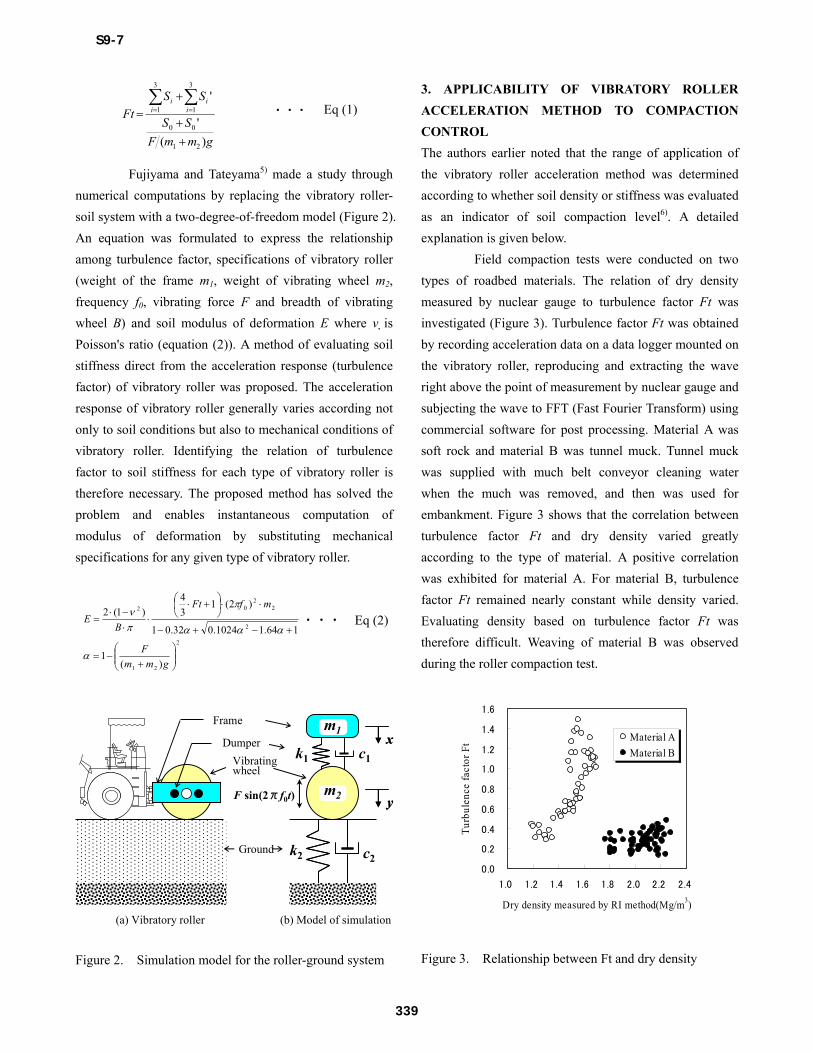
Fujiyama and Tateyama5) made a study through
numerical computations by replacing the vibratory roller-
soil system with a two-degree-of-freedom model (Figure 2).
An equation was formulated to express the relationship
among turbulence factor, specifications of vibratory roller
(weight of the frame m1, weight of vibrating wheel m2,
frequency f0, vibrating force F and breadth of vibrating
wheel B) and soil modulus of deformation E where ν is
Poisson's ratio (equation (2)). A method of evaluating soil
stiffness direct from the acceleration response (turbulence
factor) of vibratory roller was proposed. The acceleration
response of vibratory roller generally varies according not
only to soil conditions but also to mechanical conditions of
vibratory roller. Identifying the relation of turbulence
factor to soil stiffness for each type of vibratory roller is
therefore necessary. The proposed method has solved the
problem and enables instantaneous computation of
modulus of deformation by substituting mechanical
specifications for any given type of vibratory roller.
・・・ Eq (2)
Frame
Vibrating wheel
Ground
xx
yy
k2
m1
m2
k1 c1
c2
F sin(2πf0t)
(a) Vibratory roller (b) Model of simulation
Dumper
Figure 2. Simulation model for the roller-ground system
3. APPLICABILITY OF VIBRATORY ROLLER
ACCELERATION METHOD TO COMPACTION
CONTROL
The authors earlier noted that the range of application of
the vibratory roller acceleration method was determined
according to whether soil density or stiffness was evaluated
as an indicator of soil compaction level6). A detailed
explanation is given below.
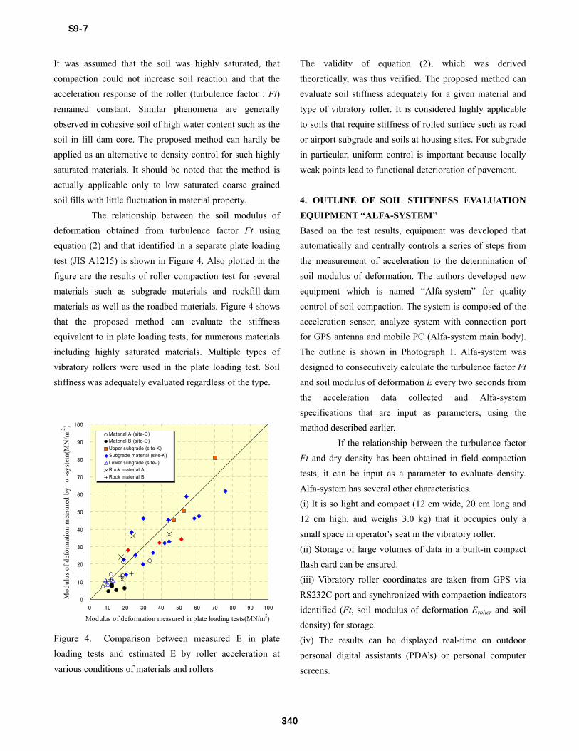
Field compaction tests were conducted on two
types of roadbed materials. The relation of dry density
measured by nuclear gauge to turbulence factor Ft was
investigated (Figure 3). Turbulence factor Ft was obtained
by recording acceleration data on a data logger mounted on
the vibratory roller, reproducing and extracting the wave
right above the point of measurement by nuclear gauge and
subjecting the wave to FFT (Fast Fourier Transform) using
commercial software for post processing. Material A was
soft rock and material B was tunnel muck. Tunnel muck
was supplied with much belt conveyor cleaning water
when the much was removed, and then was used for
embankment. Figure 3 shows that the correlation between
turbulence factor Ft and dry density varied greatly
according to the type of material. A positive correlation
was exhibited for material A. For material B, turbulence
factor Ft remained nearly constant while density varied.
Evaluating density based on turbulence factor Ft was
therefore difficult. Weaving of material B was observed
during the roller compaction test.
0.0
0.2
0.4
0.6
0.8
1.0
1.2
1.4
1.6
1.0 1.2 1.4 1.6 1.8 2.0 2.2 2.4
Dry density measured by RI method(Mg/m3)
Tur
bule
nce
fact
or F
t Material A
Material B
Figure 3. Relationship between Ft and dry density
gmmF
SS
SS
Ft i iii
)(
'
'
21
00
3
1
3
1
2
21
2
22
02
)(1
164.11024.032.01
)2(13
4
)1(2
gmm
F
mfFt
BE
S9-7
339
It was assumed that the soil was highly saturated, that
compaction could not increase soil reaction and that the
acceleration response of the roller (turbulence factor : Ft)
remained constant. Similar phenomena are generally
observed in cohesive soil of high water content such as the
soil in fill dam core. The proposed method can hardly be
applied as an alternative to density control for such highly
saturated materials. It should be noted that the method is
actually applicable only to low saturated coarse grained
soil fills with little fluctuation in material property.
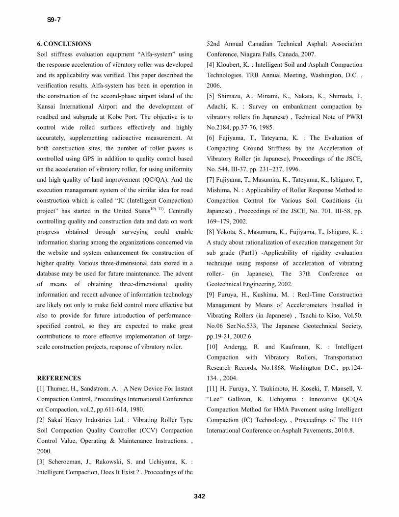
The relationship between the soil modulus of
deformation obtained from turbulence factor Ft using
equation (2) and that identified in a separate plate loading
test (JIS A1215) is shown in Figure 4. Also plotted in the
figure are the results of roller compaction test for several
materials such as subgrade materials and rockfill-dam
materials as well as the roadbed materials. Figure 4 shows
that the proposed method can evaluate the stiffness
equivalent to in plate loading tests, for numerous materials
including highly saturated materials. Multiple types of
vibratory rollers were used in the plate loading test. Soil
stiffness was adequately evaluated regardless of the type.
0
10
20
30
40
50
60
70
80
90
100
0 10 20 30 40 50 60 70 80 90 100
Modulus of deformation measured in plate loading tests(MN/m2)
Mod
ulus
of
defo
rmat
ion
mea
sure
d by
α-s
yste
m(M
N/m
2 )
Material A (site-O)Material B (site-O)
Upper subgrade (site-K)Subgrade material (site-K)
Lower subgrade (site-I)Rock material A
Rock material B
Figure 4. Comparison between measured E in plate
loading tests and estimated E by roller acceleration at
various conditions of materials and rollers
The validity of equation (2), which was derived
theoretically, was thus verified. The proposed method can
evaluate soil stiffness adequately for a given material and
type of vibratory roller. It is considered highly applicable
to soils that require stiffness of rolled surface such as road
or airport subgrade and soils at housing sites. For subgrade
in particular, uniform control is important because locally
weak points lead to functional deterioration of pavement.
4. OUTLINE OF SOIL STIFFNESS EVALUATION
EQUIPMENT “ALFA-SYSTEM”
Based on the test results, equipment was developed that
automatically and centrally controls a series of steps from
the measurement of acceleration to the determination of
soil modulus of deformation. The authors developed new
equipment which is named “Alfa-system” for quality
control of soil compaction. The system is composed of the
acceleration sensor, analyze system with connection port
for GPS antenna and mobile PC (Alfa-system main body).
The outline is shown in Photograph 1. Alfa-system was
designed to consecutively calculate the turbulence factor Ft
and soil modulus of deformation E every two seconds from
the acceleration data collected and Alfa-system
specifications that are input as parameters, using the
method described earlier.
If the relationship between the turbulence factor
Ft and dry density has been obtained in field compaction
tests, it can be input as a parameter to evaluate density.
Alfa-system has several other characteristics.
(i) It is so light and compact (12 cm wide, 20 cm long and
12 cm high, and weighs 3.0 kg) that it occupies only a
small space in operator's seat in the vibratory roller.
(ii) Storage of large volumes of data in a built-in compact
flash card can be ensured.
(iii) Vibratory roller coordinates are taken from GPS via
RS232C port and synchronized with compaction indicators
identified (Ft, soil modulus of deformation Eroller and soil
density) for storage.
(iv) The results can be displayed real-time on outdoor
personal digital assistants (PDA’s) or personal computer
screens.
S9-7
340

12cm
20cm
8cm
12cm
20cm
8cm
Acceleration sensor
α-System
GPS antenna
Vibration Roller
Mobile PC
Photograph 1. An outline of the system
Photograph 2. Field supervisors checking with PDA
Field supervisors can instantaneously access soil
quality distribution in plan on PDA screen (Photograph 2
and Figure 5) and take remedial measures promptly for
weak points. Installing a personal computer in the vibratory
roller enables the operator to carry out compaction while
confirming the level of soil compaction.
Low stiffness area
High stiffness area
E(MN/m2)
Figure 5. An example of real-time monitor
5. SYSTEM VERIFICATION THROUGH FIELD
TESTS
To verify the applicability of the developed system, a field
roller compaction test was conducted. The test yard is
outlined in Figure 6. Decomposed granite soils with a
maximum grain size of 9.5 mm were used in the test. To
verify the accuracy of detecting the points of low stiffness
by the system, a high-water-content zone was built in the
yard where water was added artificially. Initial density and
water content measured by radioactive gauges are also
provided in Figure 6. The soil modulus of deformation
measured in plate loading tests and using handy falling
weight deflectometers was compared with that output by
the control equipment. The result (distribution of soil
stiffness after 16 passes of roller) is shown in Figure 7. The
figure shows that soil modulus of deformation E output by
the control equipment was in good agreement with that
measured in plate loading tests and by falling weight
deflectometers and that E adequately represented low
stiffness in low water content zone in particular. The
control system can also be operated remotely from places a
dozen meters away via wireless LAN (local area network).
Field applicability as a practical field control system was
thus verified.
Measuring points of plate loading testMeasuring points of RI,HFWD
ρd=1.56(t/m3)wn=15.7(%)
Standard area Standard area
ρd=1.56(t/m3)wn=13.9(%)
ρd=1.58(t/m3)wn=17.0(%)
Base Concrete surface
Sand
Unit : mm
Wet area
Figure 6. Outline of the field compaction test
0
10
20
30
40
50
0 5 10 15 20 25 30Distance (m)
Mo
du
lus
of d
efo
rma
tion
E (
MN
/m2)
α-systemPlate loading testHFWD
Standard area Wet area Standard area
N=16
Figure 7.Measured and estimated distribution of modulus
of deformation E
S9-7
341
6. CONCLUSIONS
Soil stiffness evaluation equipment “Alfa-system” using
the response acceleration of vibratory roller was developed
and its applicability was verified. This paper described the
verification results. Alfa-system has been in operation in
the construction of the second-phase airport island of the
Kansai International Airport and the development of
roadbed and subgrade at Kobe Port. The objective is to
control wide rolled surfaces effectively and highly
accurately, supplementing radioactive measurement. At
both construction sites, the number of roller passes is
controlled using GPS in addition to quality control based
on the acceleration of vibratory roller, for using uniformity
and high quality of land improvement (QC/QA). And the
execution management system of the similar idea for road
construction which is called “IC (Intelligent Compaction)
project” has started in the United States10) 11). Centrally
controlling quality and construction data and data on work
progress obtained through surveying could enable
information sharing among the organizations concerned via
the website and system enhancement for construction of
higher quality. Various three-dimensional data stored in a
database may be used for future maintenance. The advent
of means of obtaining three-dimensional quality
information and recent advance of information technology
are likely not only to make field control more effective but
also to provide for future introduction of performance-
specified control, so they are expected to make great
contributions to more effective implementation of large-
scale construction projects, response of vibratory roller.
REFERENCES
[1] Thurner, H., Sandstrom. A. : A New Device For Instant
Compaction Control, Proceedings International Conference
on Compaction, vol.2, pp.611-614, 1980.
[2] Sakai Heavy Industries Ltd. : Vibrating Roller Type
Soil Compaction Quality Controller (CCV) Compaction
Control Value, Operating & Maintenance Instructions. ,
2000.
[3] Scherocman, J., Rakowski, S. and Uchiyama, K. :
Intelligent Compaction, Does It Exist ? , Proceedings of the
52nd Annual Canadian Technical Asphalt Association
Conference, Niagara Falls, Canada, 2007.
[4] Kloubert, K. : Intelligent Soil and Asphalt Compaction
Technologies. TRB Annual Meeting, Washington, D.C. ,
2006.
[5] Shimazu, A., Minami, K., Nakata, K., Shimada, I.,
Adachi, K. : Survey on embankment compaction by
vibratory rollers (in Japanese) , Technical Note of PWRI
No.2184, pp.37-76, 1985.
[6] Fujiyama, T., Tateyama, K. : The Evaluation of
Compacting Ground Stiffness by the Acceleration of
Vibratory Roller (in Japanese), Proceedings of the JSCE,
No. 544, III-37, pp. 231–237, 1996.
[7] Fujiyama, T., Masumira, K., Tateyama, K., Ishiguro, T.,
Mishima, N. : Applicability of Roller Response Method to
Compaction Control for Various Soil Conditions (in
Japanese) , Proceedings of the JSCE, No. 701, III-58, pp.
169–179, 2002.
[8] Yokota, S., Masumura, K., Fujiyama, T., Ishiguro, K. :
A study about rationalization of execution management for
sub grade (Part1) -Applicability of rigidity evaluation
technique using response of acceleration of vibrating
roller.- (in Japanese), The 37th Conference on
Geotechnical Engineering, 2002.
[9] Furuya, H., Kushima, M. : Real-Time Construction
Management by Means of Accelerometers Installed in
Vibrating Rollers (in Japanese) , Tsuchi-to Kiso, Vol.50.
No.06 Ser.No.533, The Japanese Geotechnical Society,
pp.19-21, 2002.6.
[10] Andergg, R. and Kaufmann, K. : Intelligent
Compaction with Vibratory Rollers, Transportation
Research Records, No.1868, Washington D.C., pp.124-
134. , 2004.
[11] H. Furuya, Y. Tsukimoto, H. Koseki, T. Mansell, V.
“Lee” Gallivan, K. Uchiyama : Innovative QC/QA
Compaction Method for HMA Pavement using Intelligent
Compaction (IC) Technology, , Proceedings of The 11th
International Conference on Asphalt Pavements, 2010.8.
S9-7
342