Embed Size (px)
Citation preview
The Pacific Journal of Science and Technology –69– http://www.akamaiuniversity.us/PJST.htm Volume 12. Number 2. November 2011 (Fall)
Development of Metallographic Specimen Polishing Machine.
T.J. Erinle1; O.O. Awopetu2; and O.K. Ukoba1
1Engineering Materials Development Institute, Akure, Nigeria.
2Federal University of Technology, Akure, Nigeria.
E-mail: [email protected]
ABSTRACT One of the most useful pieces of equipment for the grinding and polishing metallic materials in order to determine their physical structure using microscopy is metallographic specimen polishing machine. The objectives of the project are to design and construct a machine that will polish metal for physical metallographic determination and also to design and construct a machine using locally available materials to produce a flat, smooth and mirror-like surface of any metallic materials in order to determine their physical structure using microscopy. The machine consists of motor, pulleys, belt, rotating shaft, wooden disk plate, bush bearing, pillow bearings, metal clip, and metal casing. All of these components are assembled to form the polishing machine. The testing and evaluation of the machine involves test running of the machine at each speed rate without placing any metallic specimen on and also running after that metallic specimen was introduced for grinding and polishing. The machine has the ability to grind and polish any kind of metals, is simple to operate, and requires minimum maintenance. The metallographic specimen polishing machine can be used in the material laboratory for the grinding and polishing of any metallic materials. In all, the machine cost N52,170 ($350) to produce.
(Keywords: polishing machine, metallographic, grinding, manufacture, local components)
INTRODUCTION In the sciences and technology, Leonardo da Vinci was a pioneer, creating machines for the production of optical devices. Indeed, between 1513 and 1517, he imagined machines to grind and polish telescope mirrors, which, at the time, were made of bronze. Unfortunately, it seems
that, during his life, Leonardo da Vinci didn't actually build his invention, as he often did with other inventions. In the early 17th century, progress in the theory of optics and mastery in the production of quality glass led to the development, especially in Italy, of craftsmen specialized in the making of lenses for medical glasses, microscopes, field glasses, refractors, etc. At the time, specific tools were invented to facilitate the work of opticians, in particular machines whose principles were developed by Descartes, Huygens, Hooke, Helvelius, Cherubin d'Orleans, and others. Huygens’ lens polishing machine (1683) and Cherubin d'Orleans (1670) machines were notable examples of this era. During that period until the end of the 19th century, the refractor had been dominant since Galileo had made it famous. Leonardo da Vinci's idea of using a mirror to build an astronomical instrument remained ignored until Jacques Grégory (1663), later followed by Isaac Newton, revived it with the reflecting telescopes that still bear their names, even today. The first telescope mirrors were small bronze disks that were hand shaped. But once they reached wider dimensions it soon became indispensable to use machines to shape and polish them. In this historical evolution the first amateurs were the most famous astronomers. As early as 1788, William Herschel (1738-1822) built a polishing machine that allowed him to complete a 50' mirror, in 1789. Unfortunately there is no description left of this machine that William Herschel kept secret until his death. He only says that its fabrication was necessary to replace the number of workers necessary to complete his larger mirrors, a number that would, at times, amount to a dozen men. Yet, a small polishing machine of his making can be seen at his museum in Bath, England.
The Pacific Journal of Science and Technology –70– http://www.akamaiuniversity.us/PJST.htm Volume 12. Number 2. November 2011 (Fall)
In William Herschel's footsteps, Lord Rosse (1800-1867), a rich landowner and an amateur astronomer, launched in 1843 the making of a 183cm bronze mirror for his telescope, called the Parsonstown Leviathan, that can still be seen in Ireland. For this, he used a polishing machine which he described as early as 1841, for the benefit of the Royal Society. Later on, still another amateur, a rich merchant, William Lassell (1799-1880), used a polishing machine for the creation of large-sized mirrors (notably a 122cm mirror that was set up in Malta in 1855). But throughout this saga, we also encounter professionals among whom Henry Draper (1837-1882) who was one of the first to carve mirrors in application of Leon Foucault studies. For this purpose, around 1850, he invented a machine inspired by the one designed by Lord Rosse in 1840, which for a long time was the benchmark. This type of machine is still known today under his name. More recently, George Willis Ritchey, in his turn, improved and used the same type of machine, in the United States first (particularly for the making of the 2.5 meter mirror destined for the Mount Wilson Hooker telescope) then in France at the optics laboratory of the Dina foundation at the Paris observatory. After his stay in France, he left behind him two machines and a project for another with an 8 meter capacity, which was never built. George Willis Ritchey's polishing machine (1890) in his workshop in the United States. Two meters polishing machine designed by G.W. Ritchey for the Dina laboratory at the Paris observatory (from 1924). Eight meters machine projected by G.W. Ritchey. As for Bernhard Schmidt (1879-1935), he used another type of machine. Its movements were activated with the foot, due to his limited financial means. This fact didn't prevent him from producing high quality mirrors though. In the 20th century, with the building of large telescopes at professional observatories, polishing machines became more and more gigantic as well as more and more sophisticated. From that point of view, computer science allowed major advances with the development of revolutionary techniques perfected by specialized firms (Zeiss, REOSC). For instance, robots of the same type used in the automobile industry are entirely driven by computers to complete mirror polishing and figuring. This way the movements
and the pressures are controlled, as are the deformations of the stand for the polishing of the mirror and of the lap (these are known as the of stressed-mirror or stressed-lap techniques). Besides, the use of such robots allows improvements of the machine's program following the results obtained. Early in the history of 'modern' amateur astronomy we can find references to the use of machines. Indeed, as early as August 1922, Paul Vincart describes one of them in an issue of the "Ciel et Terre" magazine, of the Belgian Astronomical Society (Société Belge d'Astronomie). Later on, in the 1930's, in the United States, Albert Ingalls mentions different types of machines in his foundational book (Amateur Telescope Making). In France, one can read descriptions of such machines in an issue of the "Astronomie" magazine of the SAF (Société Française d'Astronomie) dealing with the 108th session of the commission in charge of instruments, in February 1958. For a long time, amateur mirror makers have been exploring the positive points of machines. One can give the names of Pierre Bourge, Félix Bacchi, or, more recently, Dany Cardoen. Yet, in our country, these techniques have never been as popular as on the other side of the Atlantic. This phenomenon may be explained by the fact that the bible of French amateur mirror makers, "La construction du télescope d'amateur", written by Jean Texereau, never said a word about these tools. Thanks to the recent development of Internet exchanges, one can read many testimonials by amateurs benefitting from the community of amateur makers. Draper machine and a Hindle machine by Jean Texereau, published in L'Astronomie' magazine, in 1958. Eventually, these machines were also used as allies by independent professional mirror makers. In France, the late Roger Mosser used one of them decades ago. The same applies today to his followers, Franck Grière (Mirro-Sphère) and Jean-Marc Lecleire (Astrotélescope). In the USA, one such example is Carl Zambuto, a professional who generously shares his knowledge and his techniques throughout the amateur community. We must also mention another American, Mike Lockwood, and an Italian, Romano Zen.
The Pacific Journal of Science and Technology –71– http://www.akamaiuniversity.us/PJST.htm Volume 12. Number 2. November 2011 (Fall)
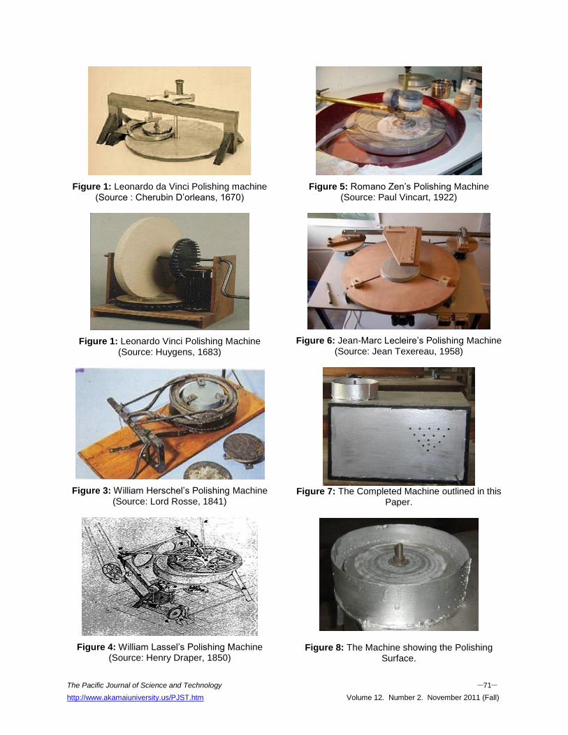
Figure 1: Leonardo da Vinci Polishing machine (Source : Cherubin D’orleans, 1670)
Figure 1: Leonardo Vinci Polishing Machine (Source: Huygens, 1683)
Figure 3: William Herschel’s Polishing Machine (Source: Lord Rosse, 1841)
Figure 4: William Lassel’s Polishing Machine (Source: Henry Draper, 1850)
Figure 5: Romano Zen’s Polishing Machine (Source: Paul Vincart, 1922)
Figure 6: Jean-Marc Lecleire’s Polishing Machine (Source: Jean Texereau, 1958)
Figure 7: The Completed Machine outlined in this
Paper.
Figure 8: The Machine showing the Polishing Surface.
The Pacific Journal of Science and Technology –72– http://www.akamaiuniversity.us/PJST.htm Volume 12. Number 2. November 2011 (Fall)
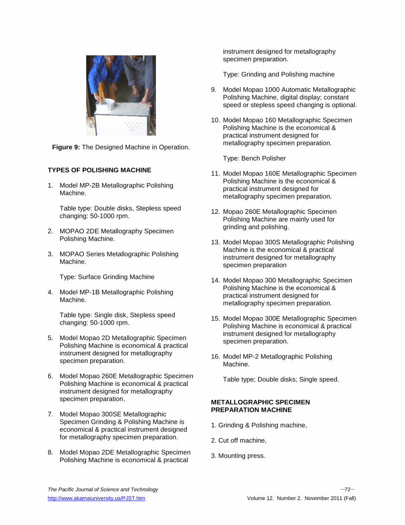
Figure 9: The Designed Machine in Operation.
TYPES OF POLISHING MACHINE 1. Model MP-2B Metallographic Polishing
Machine. Table type: Double disks, Stepless speed changing: 50-1000 rpm.
2. MOPAO 2DE Metallography Specimen Polishing Machine.
3. MOPAO Series Metallographic Polishing Machine. Type: Surface Grinding Machine
4. Model MP-1B Metallographic Polishing Machine. Table type: Single disk, Stepless speed changing: 50-1000 rpm.
5. Model Mopao 2D Metallographic Specimen Polishing Machine is economical & practical instrument designed for metallography specimen preparation.
6. Model Mopao 260E Metallographic Specimen Polishing Machine is economical & practical instrument designed for metallography specimen preparation.
7. Model Mopao 300SE Metallographic Specimen Grinding & Polishing Machine is economical & practical instrument designed for metallography specimen preparation.
8. Model Mopao 2DE Metallographic Specimen Polishing Machine is economical & practical
instrument designed for metallography specimen preparation. Type: Grinding and Polishing machine
9. Model Mopao 1000 Automatic Metallographic Polishing Machine, digital display; constant speed or stepless speed changing is optional.
10. Model Mopao 160 Metallographic Specimen Polishing Machine is the economical & practical instrument designed for metallography specimen preparation. Type: Bench Polisher
11. Model Mopao 160E Metallographic Specimen Polishing Machine is the economical & practical instrument designed for metallography specimen preparation.
12. Mopao 260E Metallographic Specimen Polishing Machine are mainly used for grinding and polishing.
13. Model Mopao 300S Metallographic Polishing Machine is the economical & practical instrument designed for metallography specimen preparation
14. Model Mopao 300 Metallographic Specimen Polishing Machine is the economical & practical instrument designed for metallography specimen preparation.
15. Model Mopao 300E Metallographic Specimen Polishing Machine is economical & practical instrument designed for metallography specimen preparation.
16. Model MP-2 Metallographic Polishing Machine. Table type; Double disks; Single speed.
METALLOGRAPHIC SPECIMEN PREPARATION MACHINE 1. Grinding & Polishing machine, 2. Cut off machine, 3. Mounting press.
The Pacific Journal of Science and Technology –73– http://www.akamaiuniversity.us/PJST.htm Volume 12. Number 2. November 2011 (Fall)
METHODOLOGY Material Selection
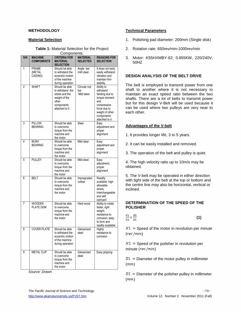
Table 1: Material Selection for the Project Components.
S/N MACHINE COMPONENTS
CRITERIA FOR MATERIAL SELECTION
MATERIAL SELECTED
REASONS FOR SELECTION
1 FRAME (METAL CASING)
Should be able to withstand the eccentric motion of the machine during operation
Angle bar mild steel
It does not twist, easily withstand vibration and maintain firm stability
2 SHAFT Should be able to withstand the stress and the weight of the other components attached to it
Circular rod bar Mild steel
Ability to withstand twisting due to torque moment and compressive force due to weight of other components attached to it.
3 PILLOW BEARING
Should be able to overcome torque from the machine and the motor
Steel Easy adjustment and proper alignment
4 BUSH BEARING
Should be able to overcome torque from the machine and the motor
Mild steel Easy adjustment and proper alignment
5 PULLEY Should be able to overcome torque from the machine and the motor
Mild steel Easy adjustment. proper alignment
6 BELT Should be able to overcome torque from the machine and the motor
Impregnated rubber
Readily available, high allowable stress, interchangeable and self lubricant
7 WOODEN PLATE DISK
Should be able to overcome torque from the machine and the motor
Hard wood Ability to rotate faster, light weight, resistance to corrosion, easy to form and readily available
8 COVER PLATE Should be able to withstand the eccentric motion of the machine during operation
Galvanized steel
Highly resistance to corrosion
9 METAL CLIP Should be able to overcome torque from the machine and the motor
Galvanized steel
Easy gripping
Source: Drawn
Technical Parameters 1. Polishing pad diameter: 200mm (Single disk)
2. Rotation rate: 650rev/min-1000rev/min
3. Motor: K55HXMBY-62; 0.855KW, 220/240V,
50HZ DESIGN ANALYSIS OF THE BELT DRIVE The belt is employed to transmit power from one shaft to another where it is not necessary to maintain an exact speed ratio between the two shafts. There are a lot of belts to transmit power but for this design V-Belt will be used because it can be used where two pulleys are very near to each other. Advantages of the V-belt 1. It provides longer life, 3 to 5 years. 2. It can be easily installed and removed. 3. The operation of the belt and pulley is quiet. 4. The high velocity ratio up to 10m/s may be obtained. 5. The V-belt may be operated in either direction with tight side of the belt at the top or bottom and the centre line may also be horizontal, vertical or inclined. DETERMINATION OF THE SPEED OF THE POLISHER
= (1)
Speed of the motor in revolution per minute
( )
Speed of the polisher in revolution per
minute ( )
Diameter of the motor pulley in millimeter
( )
Diameter of the polisher pulley in millimeter
( )
The Pacific Journal of Science and Technology –74– http://www.akamaiuniversity.us/PJST.htm Volume 12. Number 2. November 2011 (Fall)
Data:
?
= 100mm
= 50mm
=
=
=
= 1000 rev/min
The maximum speed of the polisher, N2 is
1000
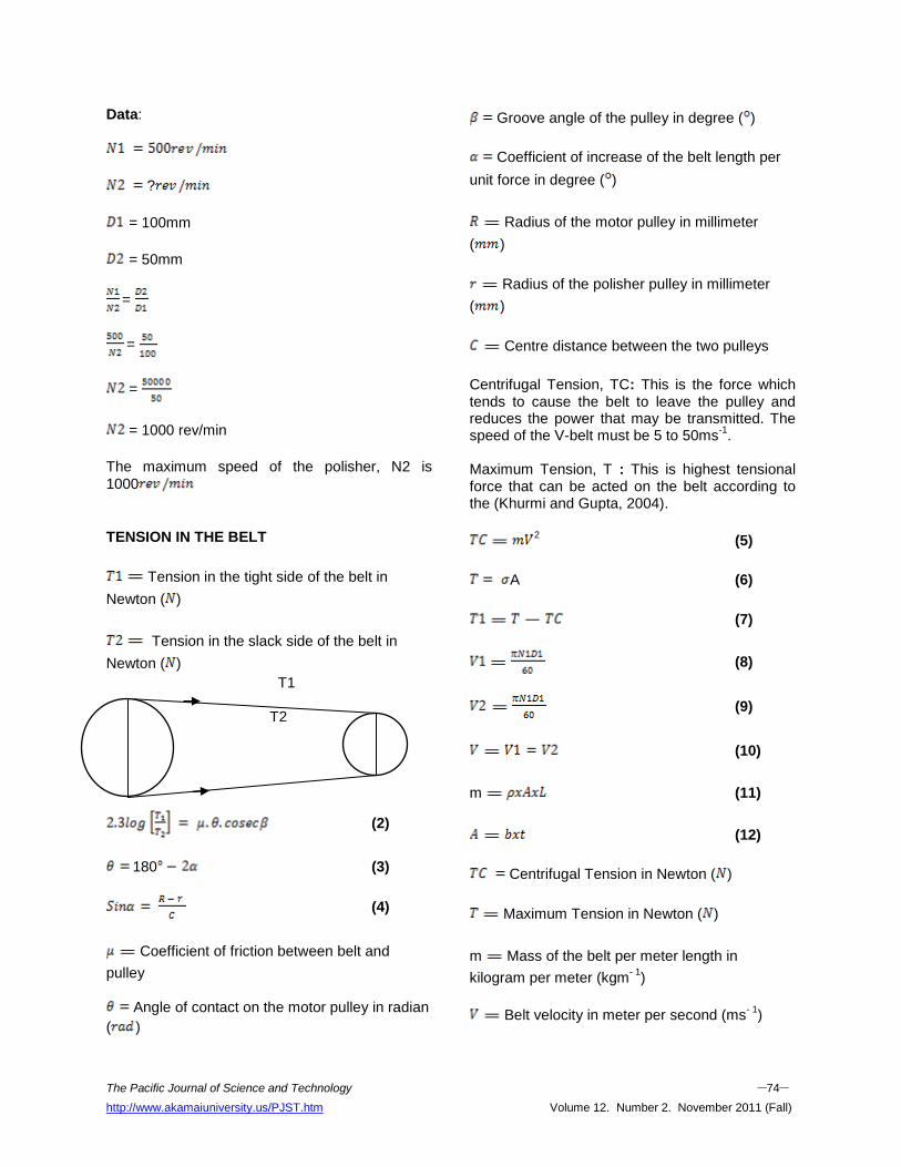
TENSION IN THE BELT
Tension in the tight side of the belt in
Newton ( )
Tension in the slack side of the belt in
Newton ( )
T1 T2
(2)
180 (3)
(4)
Coefficient of friction between belt and
pulley
Angle of contact on the motor pulley in radian
( )
Groove angle of the pulley in degree ( )
Coefficient of increase of the belt length per
unit force in degree ( )
Radius of the motor pulley in millimeter
( )
Radius of the polisher pulley in millimeter
( )
Centre distance between the two pulleys
Centrifugal Tension, TC: This is the force which tends to cause the belt to leave the pulley and reduces the power that may be transmitted. The speed of the V-belt must be 5 to 50ms
-1.
Maximum Tension, T : This is highest tensional force that can be acted on the belt according to the (Khurmi and Gupta, 2004).
2 (5)
A (6)
(7)
(8)
(9)
(10)
m (11)
(12)
Centrifugal Tension in Newton ( )
Maximum Tension in Newton ( )
m Mass of the belt per meter length in
kilogram per meter (kgm- 1
)
Belt velocity in meter per second (ms
- 1)
The Pacific Journal of Science and Technology –75– http://www.akamaiuniversity.us/PJST.htm Volume 12. Number 2. November 2011 (Fall)
( ) Belt density in kilogram per meter cube
(kgm- 3
)
Cross sectional area in square millimeter
(mm 2)
Belt width in millimeter (mm)
Belt thickness in millimeter (mm)
Allowable stress in Newton per square
millimeter (Nmm- 2
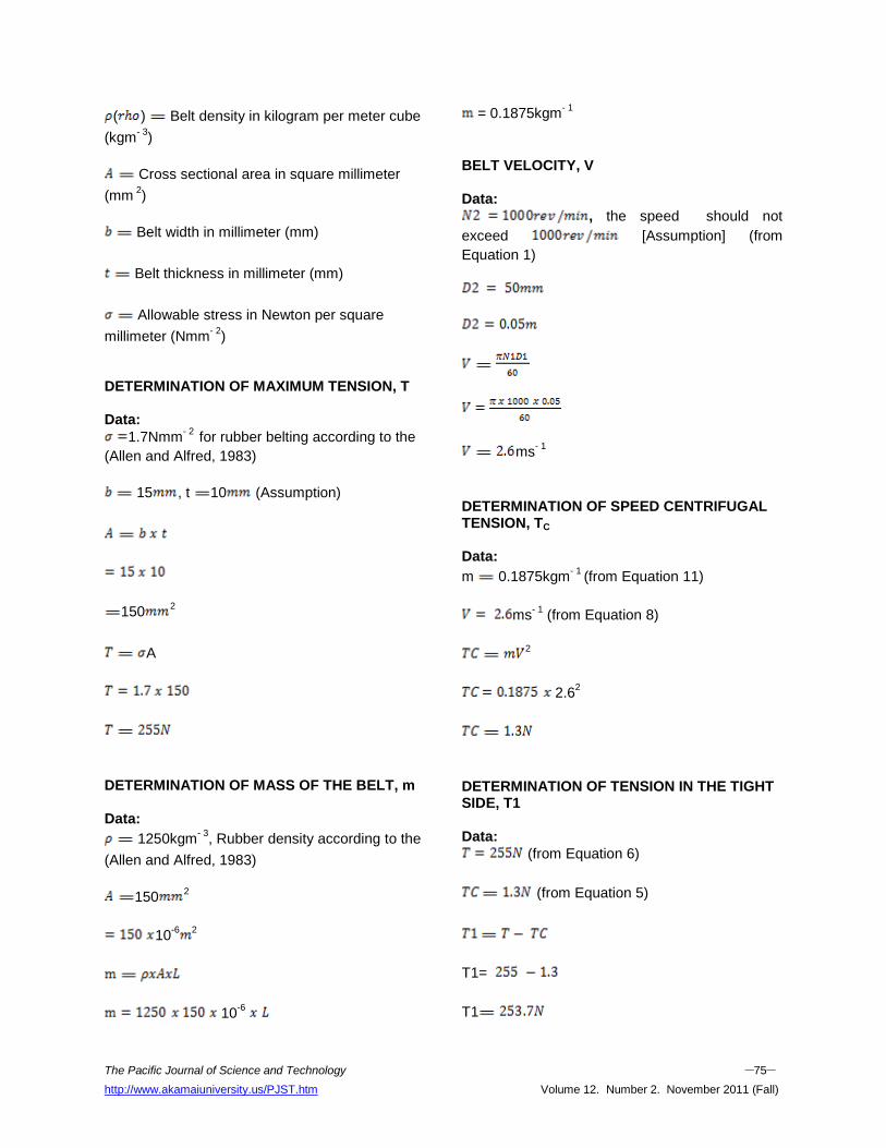
) DETERMINATION OF MAXIMUM TENSION, T Data:
1.7Nmm- 2
for rubber belting according to the
(Allen and Alfred, 1983)
15 , t 10 (Assumption)
1502
A
DETERMINATION OF MASS OF THE BELT, m Data:
1250kgm- 3
, Rubber density according to the
(Allen and Alfred, 1983)
1502
10-6 2
10-6
= 0.1875kgm- 1
BELT VELOCITY, V Data:
, the speed should not
exceed [Assumption] (from
Equation 1)
ms
- 1
DETERMINATION OF SPEED CENTRIFUGAL TENSION, TC
Data:
m 0.1875kgm- 1
(from Equation 11)
ms- 1
(from Equation 8)
2
2.62
DETERMINATION OF TENSION IN THE TIGHT SIDE, T1 Data:
(from Equation 6)
(from Equation 5)
T1=
T1
The Pacific Journal of Science and Technology –76– http://www.akamaiuniversity.us/PJST.htm Volume 12. Number 2. November 2011 (Fall)
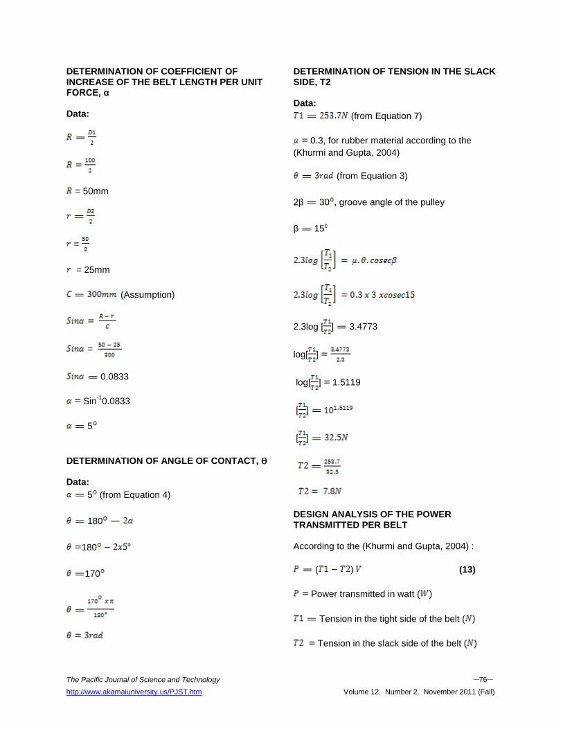
DETERMINATION OF COEFFICIENT OF INCREASE OF THE BELT LENGTH PER UNIT FORCE, α Data:
= 50mm
=
= 25mm
(Assumption)
=
0.0833
Sin-1
0.0833
5
DETERMINATION OF ANGLE OF CONTACT, ϴ Data:
5 (from Equation 4)
180
180
170
DETERMINATION OF TENSION IN THE SLACK SIDE, T2 Data:
(from Equation 7)
0.3, for rubber material according to the
(Khurmi and Gupta, 2004)
(from Equation 3)
2β 30 , groove angle of the pulley
β 15
2.3log [ ] 3.4773
log[ ]
log[ ] 1.5119
[ ]
[ ]
DESIGN ANALYSIS OF THE POWER TRANSMITTED PER BELT According to the (Khurmi and Gupta, 2004) :
( ) (13)
Power transmitted in watt ( )
Tension in the tight side of the belt ( )
Tension in the slack side of the belt ( )
The Pacific Journal of Science and Technology –77– http://www.akamaiuniversity.us/PJST.htm Volume 12. Number 2. November 2011 (Fall)
Belt velocity (ms- 1
)
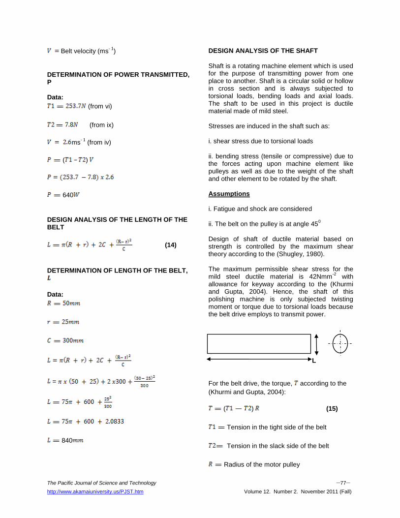
DETERMINATION OF POWER TRANSMITTED, P Data:
(from vi)
(from ix)
ms- 1
(from iv)
( )
640
DESIGN ANALYSIS OF THE LENGTH OF THE BELT
(14)
DETERMINATION OF LENGTH OF THE BELT,
Data:
=
840
DESIGN ANALYSIS OF THE SHAFT Shaft is a rotating machine element which is used for the purpose of transmitting power from one place to another. Shaft is a circular solid or hollow in cross section and is always subjected to torsional loads, bending loads and axial loads. The shaft to be used in this project is ductile material made of mild steel. Stresses are induced in the shaft such as: i. shear stress due to torsional loads ii. bending stress (tensile or compressive) due to the forces acting upon machine element like pulleys as well as due to the weight of the shaft and other element to be rotated by the shaft. Assumptions i. Fatigue and shock are considered ii. The belt on the pulley is at angle 45
0
Design of shaft of ductile material based on strength is controlled by the maximum shear theory according to the (Shugley, 1980). The maximum permissible shear stress for the mild steel ductile material is 42Nmm
-2 with
allowance for keyway according to the (Khurmi and Gupta, 2004). Hence, the shaft of this polishing machine is only subjected twisting moment or torque due to torsional loads because the belt drive employs to transmit power.
L
For the belt drive, the torque, according to the
(Khurmi and Gupta, 2004):
( ) (15)
Tension in the tight side of the belt
Tension in the slack side of the belt
Radius of the motor pulley
The Pacific Journal of Science and Technology –78– http://www.akamaiuniversity.us/PJST.htm Volume 12. Number 2. November 2011 (Fall)
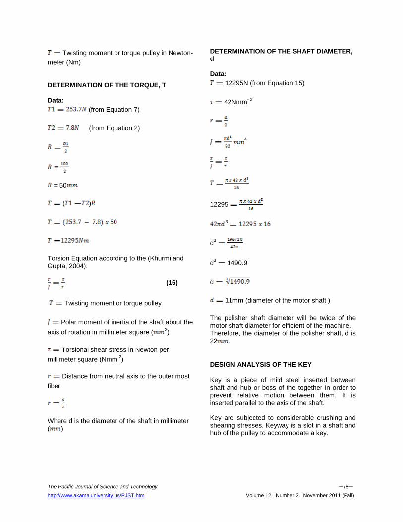
Twisting moment or torque pulley in Newton-
meter (Nm) DETERMINATION OF THE TORQUE, T Data:
(from Equation 7)
(from Equation 2)
= 50
( )
Torsion Equation according to the (Khurmi and Gupta, 2004):
(16)
Twisting moment or torque pulley
Polar moment of inertia of the shaft about the
axis of rotation in millimeter square (2)
Torsional shear stress in Newton per
millimeter square (Nmm-2
)
Distance from neutral axis to the outer most
fiber
Where d is the diameter of the shaft in millimeter
( )
DETERMINATION OF THE SHAFT DIAMETER, d Data:
12295N (from Equation 15)
42Nmm- 2
4
12295
3
d3
d3 1490.9
d
11mm (diameter of the motor shaft )
The polisher shaft diameter will be twice of the motor shaft diameter for efficient of the machine. Therefore, the diameter of the polisher shaft, d is
22 .
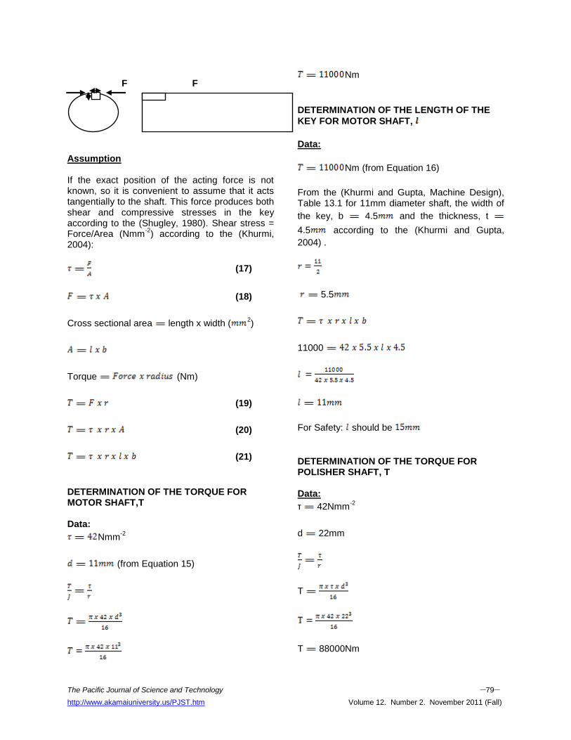
DESIGN ANALYSIS OF THE KEY Key is a piece of mild steel inserted between shaft and hub or boss of the together in order to prevent relative motion between them. It is inserted parallel to the axis of the shaft. Key are subjected to considerable crushing and shearing stresses. Keyway is a slot in a shaft and hub of the pulley to accommodate a key.
The Pacific Journal of Science and Technology –79– http://www.akamaiuniversity.us/PJST.htm Volume 12. Number 2. November 2011 (Fall)
F F Assumption If the exact position of the acting force is not known, so it is convenient to assume that it acts tangentially to the shaft. This force produces both shear and compressive stresses in the key according to the (Shugley, 1980). Shear stress = Force/Area (Nmm
-2) according to the (Khurmi,
2004):
(17)
(18)
Cross sectional area length x width (2)
Torque (Nm)
(19)
(20)
(21)
DETERMINATION OF THE TORQUE FOR MOTOR SHAFT,T Data:
Nmm-2
(from Equation 15)
Nm
DETERMINATION OF THE LENGTH OF THE
KEY FOR MOTOR SHAFT,
Data:
Nm (from Equation 16)
From the (Khurmi and Gupta, Machine Design), Table 13.1 for 11mm diameter shaft, the width of
the key, b 4.5 and the thickness, t
4.5 according to the (Khurmi and Gupta,
2004) .
5.5
11000
For Safety: should be
DETERMINATION OF THE TORQUE FOR POLISHER SHAFT, T Data:
τ 42Nmm-2
d 22mm
T
T 88000Nm
The Pacific Journal of Science and Technology –80– http://www.akamaiuniversity.us/PJST.htm Volume 12. Number 2. November 2011 (Fall)
DETERMINATION OF THE LENGTH OF THE
KEY FOR POLISHER SHAFT,
Data:
T 88000Nm (from Equation 16)
From the (Khurmi and Gupta, Machine Design), Table 1 for 22mm diameter shaft, the width of the
key, b 8mm and the thickness, t 7mm
according to the (Khurmi and Gupta, 2004) .
11mm
T
88000
24mm
For Safety: should be 30mm
CONCLUSION The locally made metallographic specimen polishing machine gave the good results when compared with the imported one. It gave accurate results when used to grind and polish metallic materials during testing and evaluation. In conclusion, the machine has been designed, constructed and tested. The satisfactory performance of the metallographic specimen polishing machine proved that aim and objective of the project was achieved. During the test, it was discovered that all the level of speeds has important role to play in giving good, smooth including fine grinding and polishing. The machine efficiency increases at each level of speeds. The high speed has high number of strokes and the low speed has low number of strokes. The machine has the ability to grind and polish any kind of metals, simple to operate and requires minimum maintenance.
REFERENCES 1. Allen, S.H. Jr. and R.H. Alfred. 1983. Theory and
Problems of Machine Design. McGraw-Hill Publishing Co.: New York, NY.
2. American Society for Metal (ASM). 1992. Handbook on Metallography and Microstructures Vol.9.
3. Khurmi, R.S. 2004. Strength of Materials. S. Chand and Company Ltd.: Ram Nagar, New Delhi, India. 110-055.
4. Khurmi, R.S. and Gupta, J.K. 2004. Machine Design, Eurasia Publishing House (PVT) Ltd.: Ram Nagar, New Delhi, India. 110-055.
5. Leonard, E.S. 2003. Metallographic Polishing by Mechanical Methods. (4th Edition).
6. Raymond, A.H. 1993. Applied Physical Metallurgy. (6th Edition). New York, NY.
7. Shugley, J.E. 1980. Design of Machine Element. (5th Edition). McGraw-Hill Publishing Co.: New York, NY.
8. Smith, C.S. 1990. History of Metallography. Metal Park, Ohio. 5-14.
9. Portail d'Astronomie des Astronomes Amateurs Francophones. 2010. “A history of Polishing Machines”. www.astrosurf.com. retrieved on 28/10/10.
ABOUT THE AUTHORS T.J. Erinle, is a Mechanical Engineer in the Technical Department, Engineering Materials Development Institute, Akure, Nigeria. He holds a HND degree in Mechanical Engineering and currently doing his PDG in Mechanical Engineering. His research interests are in the areas of industrial engineering. O.O. Awopetu, is a Engineer at the Federal University of Technology Akure, Nigeria with research interests are in the areas of production and industrial engineering. O.K. Ukoba, is a Design and Simulation Engineer in the Manufacturing Department, Engineering Materials Development Institute, Akure, Nigeria. He holds a B.Eng. degree in Mechanical Engineering and currently doing his M.Eng. in Mechanical Engineering. His research interests are in the areas of design/simulation,

The Pacific Journal of Science and Technology –81– http://www.akamaiuniversity.us/PJST.htm Volume 12. Number 2. November 2011 (Fall)
materials (testing and synthesis), corrosion, and ergonomics. SUGGESTED CITATION Erinle, T.J., O.O. Awopetu, and O.K. Ukoba. 2011. “Development of Metallographic Specimen Polishing Machine”. Pacific Journal of Science and Technology. 12(2):69-81.
Pacific Journal of Science and Technology