Embed Size (px)
Citation preview
DEVELOPMENT OF KERNEL FOR RISC
ARCHITECTURE SYSTEM
NG CHUN HONG
MASTER OF COMPUTER SCIENCE
FACULTY OF ENGINEERING AND SCIENCE
UNIVERSITI TUNKU ABDUL RAHMAN
MAY 2014
DEVELOPMENT OF KERNEL FOR RISC
ARCHITECTURE SYSTEM
By
NG CHUN HONG
A project submitted to the Department of Internet Engineering and Computer
Science,
Faculty of Engineering and Science,
Universiti Tunku Abdul Rahman,
in partial fulfillment of the requirements for the degree of
Master of Computer Science
March 2014
TABLE OF CONTENTS
ABSTRACT iii
PERMISSION SHEET iv
APPROVAL SHEET v
DECLARATION vi
LIST OF TABLES vii
LIST OF FIGURES viii
LIST OF ABBREVIATIONS ix
1.0 Introduction 1
1.1 Introduction 1
1.2 Problem Statement 1
1.3 Project Scope 2
1.4 Project Objective 3
2.0 Literature Review 4
2.1 Computer Architecture and Operating System 4
2.2 Application Binary Interface 6
2.3 Object File Format 7
2.4 Executable and Linkable Format (ELF) 8
2.5 Assembly for Arm 9
2.6 Operating Mode 12
2.7 List of register in ARM architecture 12
2.8 Endianess 15
2.9 Kernel Functionality 15
2.9.1 Type of kernel 15
2.9.1.1 Micro Kernel 16
2.9.1.2 Monolithic kernel 16
2.10 Memory Map 16
2.11 Memory Management Unit in ARM 17
3.0 TOOLS AND METHODLOGY 21
3.1 Development methodology 21
3.2 Targeted ARM platform 23
3.3 Toolchain 23
3.4 Emulator 24
3.5 Linker/ Linker Script 26
3.6 GNU Compiler Collection (GCC) 27
3.7 GNU Project Debugger (GDB) 28
3.8 Bootloader 28
3.9 Automating Build Process 29
3.10 Source Code Management 30
4.0 DESIGN AND SPECIFICATION 31
4.1 System Environment 31
4.2 System Flowchart 32
4.3 Memory Layout 33
4.4 Product Backlog 33
4.4.1 Functional Requirement Specification 35
5.0 IMPLEMENTATION 43
5.1 Development environment (User Story 3) 43
5.1.1 Setting up toolchain 43
5.2 Linking option and script (User Story 5) 44
5.3 System Startup Script (User Story 6) 45
5.4 Automated Build Process (User Story 7) 46
5.5 Interrupt Service Routine (User Story 9) 47
5.6 System Operating Mode (User Story 10) 49
5.7 Memory Management Unit (User Story 11) 49
5.8 Supervisor Call (User Story 12) 50
5.9 Device Driver (User Story 13) 51
5.10 Porting Guide 52
6.0 Testing and Result 54
6.1 Development Environment Test Result 54
6.2 Linker Script Test Result 55
6.3 Interrupt Service Routine Test Result 56
6.3.1 Comparison On Interrupt Handling 57
6.4 Operating Mode Test Result 57
6.5 Memory Management Unit Test Result 59
6.5.1 Memory Manaagement Unit Usage In Other Kernel 60
6.6 Supervisor Call Test Result 60
6.6.1 System Call For Device Input Output 61
6.7 Device Driver Testing 61
6.7.1 Device Management in Linux Kernel 62
6.8 Project Time line 63
7.0 CONCLUSION AND FUTURE WORK 64

REFERENCE 65
APPENDIXES 67
ABSTRACT
Development of Kernel for RISC Architecture System
With the blooming on smart phone and tablet devices, the study on RISC
become important. As many has predicted that post pc era is coming near,
RISC architecture based processor is expected to be widely used. However
there is lack of a simple model and system to understand how does the
hardware and software work together. Therefore in this project, the aim is to
be able to come out with a working kernel that enabled further experiment of
different kernel architecture or other development (for example driver
development or filesystem design).
Another problem with operating system study is that the is lack of material in
understanding the design of a kernel. Most of the material discussed about
certain specific function and the design decision such as which memory model
to used is often not disclose. Thus part of the project is to review the available
design methodology and provide a simpler explanation in various aspect.
FACULTY OF ENGINEERING AND SCIENCE
UNIVERSITI TUNKU ABDUL RAHMAN
Date: 21 MAY 2014
PERMISSION SHEET
It is hereby certified that Ng Chun Hong (ID No:09UEM05353) has
completed this final year project entitled “DEVELOPMENT OF KERNEL
FOR RISC ARCHITECTURE SYSTEM” under the supervision of Mr. Mok
Kai Ming (Supervisor) from the Department of Computer and Communication
Technology, Faculty of Information and Communication Technology, and
___________________________________ (Co-Supervisor)* from the
Department of ___________________________________, Faculty of
Engineering and Science.
I hereby give permission to the University to upload softcopy of my final year
project in PDF format into UTAR Institutional Repository, which may be
made accessible to UTAR community and public.
Yours truly,
___________________
NG CHUN HONG

APPROVAL SHEET
This dissertation/thesis entitled “DEVELOPMENT OF KERNEL FOR RISC
ARCHITECTURE SYSTEM” was prepared by Ng Chun Hong and submitted
as partial fulfilment of the requirements for the degree of Master of
Computer Science at Universiti Tunku Abdul Rahman.
Approved by:
_______________________________
(Mr. Mok Kai Ming)
Date:…………………..
Professor/Supervisor
Department of Computer and Communication Technology
Faculty of Information and Communication Technology
Universiti Tunku Abdul Rahman
DECLARATION
I Ng Chun Hong hereby declare that the dissertation is based on my
original work except for quotations and citations which havebeen duly
acknowledged. I also declare that it has not been previously or concurrently
submitted for any other degree at UTAR or other institutions.
___________________
NG CHUN HONG
Date 21 MAY 2014
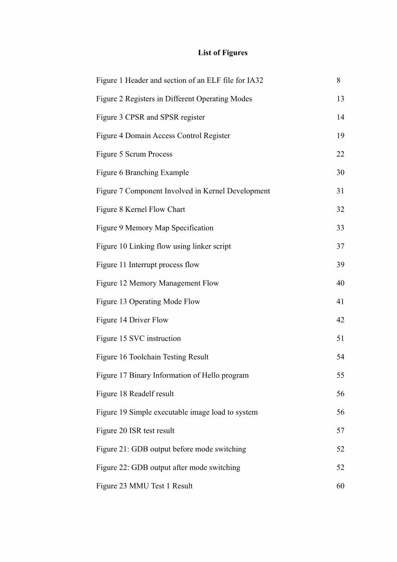
List of Figures
Figure 1 Header and section of an ELF file for IA32 8
Figure 2 Registers in Different Operating Modes 13
Figure 3 CPSR and SPSR register 14
Figure 4 Domain Access Control Register 19
Figure 5 Scrum Process 22
Figure 6 Branching Example 30
Figure 7 Component Involved in Kernel Development 31
Figure 8 Kernel Flow Chart 32
Figure 9 Memory Map Specification 33
Figure 10 Linking flow using linker script 37
Figure 11 Interrupt process flow 39
Figure 12 Memory Management Flow 40
Figure 13 Operating Mode Flow 41
Figure 14 Driver Flow 42
Figure 15 SVC instruction 51
Figure 16 Toolchain Testing Result 54
Figure 17 Binary Information of Hello program 55
Figure 18 Readelf result 56
Figure 19 Simple executable image load to system 56
Figure 20 ISR test result 57
Figure 21: GDB output before mode switching 52
Figure 22: GDB output after mode switching 52
Figure 23 MMU Test 1 Result 60
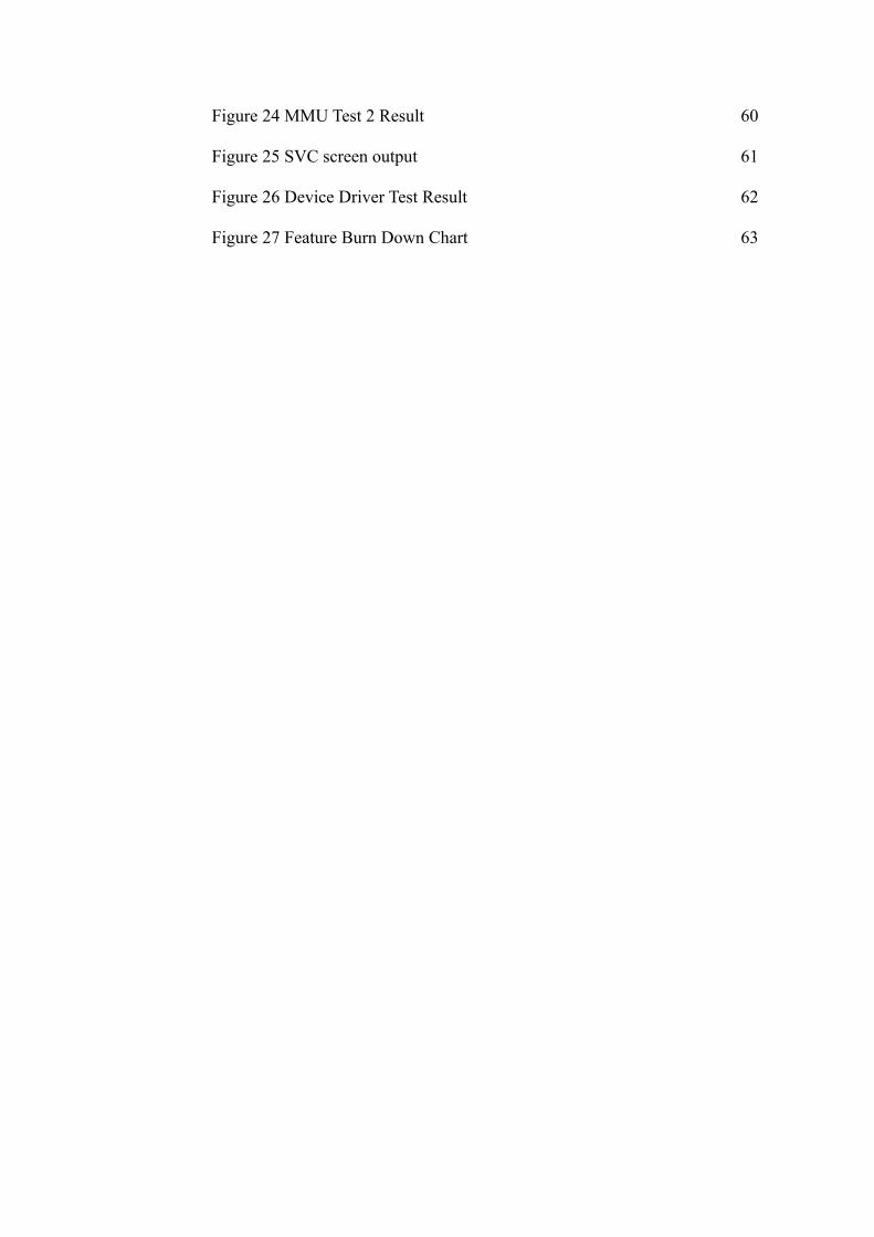
Figure 24 MMU Test 2 Result 60
Figure 25 SVC screen output 61
Figure 26 Device Driver Test Result 62
Figure 27 Feature Burn Down Chart 63
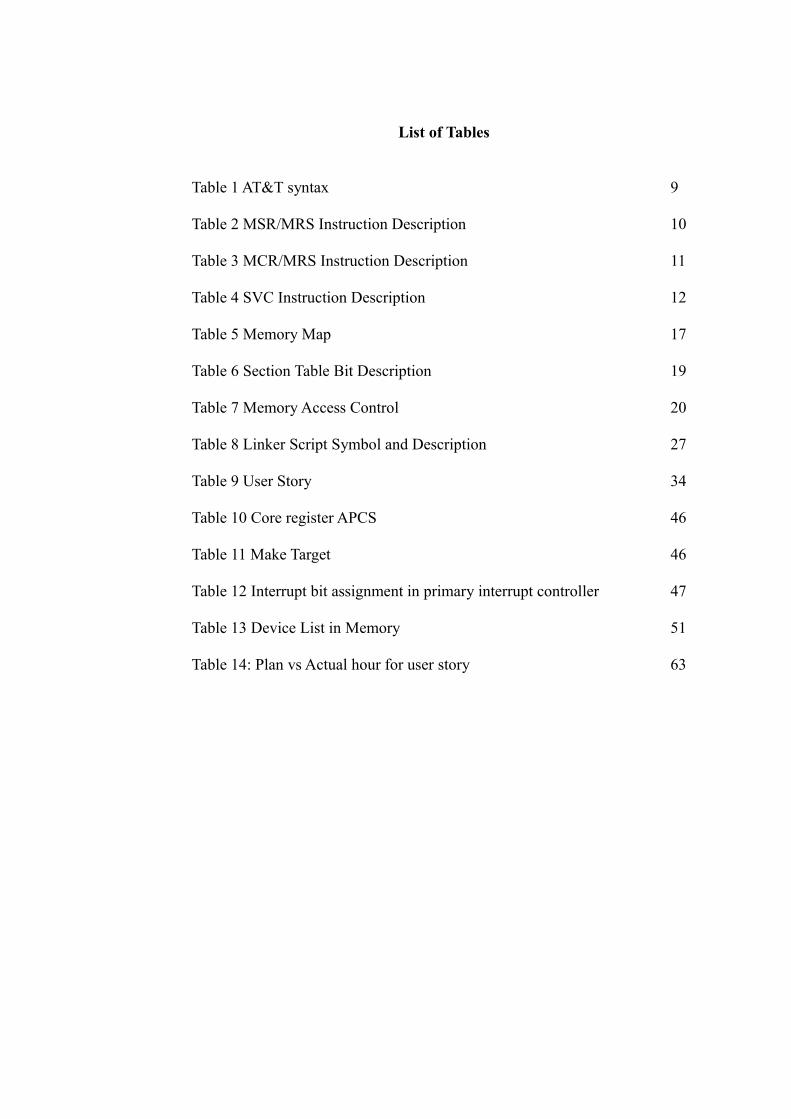
List of Tables
Table 1 AT&T syntax 9
Table 2 MSR/MRS Instruction Description 10
Table 3 MCR/MRS Instruction Description 11
Table 4 SVC Instruction Description 12
Table 5 Memory Map 17
Table 6 Section Table Bit Description 19
Table 7 Memory Access Control 20
Table 8 Linker Script Symbol and Description 27
Table 9 User Story 34
Table 10 Core register APCS 46
Table 11 Make Target 46
Table 12 Interrupt bit assignment in primary interrupt controller 47
Table 13 Device List in Memory 51
Table 14: Plan vs Actual hour for user story 63
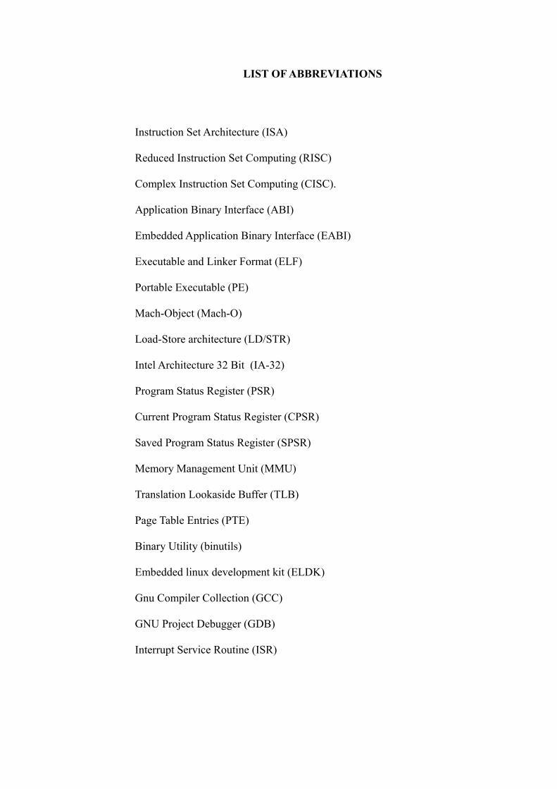
LIST OF ABBREVIATIONS
Instruction Set Architecture (ISA)
Reduced Instruction Set Computing (RISC)
Complex Instruction Set Computing (CISC).
Application Binary Interface (ABI)
Embedded Application Binary Interface (EABI)
Executable and Linker Format (ELF)
Portable Executable (PE)
Mach-Object (Mach-O)
Load-Store architecture (LD/STR)
Intel Architecture 32 Bit (IA-32)
Program Status Register (PSR)
Current Program Status Register (CPSR)
Saved Program Status Register (SPSR)
Memory Management Unit (MMU)
Translation Lookaside Buffer (TLB)
Page Table Entries (PTE)
Binary Utility (binutils)
Embedded linux development kit (ELDK)
Gnu Compiler Collection (GCC)
GNU Project Debugger (GDB)
Interrupt Service Routine (ISR)
CHAPTER 1
1.0 INTRODUCTION
1.1 Introduction
RISC architecture has and will continue to become prominence in the post pc
era especially in the area of pervasive computing and wearable computing.
They are more favorable in those areas because of the cost and power
consumption. As hardware continue to grow in both processing speed and
memory capacities, single application system has becoming more irrelevant
that ever. For example smart watches are installed with operating system and
able to run different user applications. Therefore the study on operating system
is important to create hardware and software that can work together more
effectively. Due to the complexity of matured operating system such as
Android and Linux, it is difficult to introduce and experiment with kernel
concept to beginner. Therefore in this project, the aim is to develop a
methodology to create a simple kernel targeted for ARM processor. The
outcome of the project will also be used in other project to verify the design of
a RISC architecture system.
1.2 Problem Statement
In general, the design of a processor involves verification at several levels of
abstraction. Specifically for front-end processor design, verification is
typically conducted at Register Transfer Level (RTL) and full-chip level. RTL
1
verification involves cycle-accurate functional verification, that is, observation
of the required signal events occurring at the correct clock cycle. The work is
typically hardware in nature since observation is done at signal level and
verifying the logic functionality of smaller modules. On the other hand, we
have full-chip level functional verification which involves verifying the full-
chip at transaction level. It also indirectly verify the integration of modules
which forms the full-chip or processor. We can use single standalone
programme as in embedded application programme but this type of
programme is not as extendable and complete as in a kernel function which
test the processor at full-chip level more thoroughly. With the availability of a
kernel, the processor design cycle can be reduced since both hardware and
software can be developed in parallel. After completed the full-chip
verification, the kernel can further be extended into a more complete software
with customizable features that supports the processor. Available kernel in
open source is overly complicated for extension and reuse to be adapted into
different embedded processor during the design process. Another problem
with open source kernel programmes is the lack of documentation and hence,
lack of reusability.
1.3 Project Scope
The project scope consist of the development of a generic and portable kernel
that can be adapted to verify the functionality of a RISC processor. Along with
the kernel, the methodology and tools to develop the kernel components is
also presented as part of the project outcome.
2
1.4 Project Objective
The objectives of the project are:
• Comparison between the differences of RISC and CISC architeture,
which include the instruction set and basic components of a kernel
(interrupt handling, operating mode, and memory protection).
• Develop kernel requirement – Identified and define the integration for
the needed components that provide I/O management and memory
management.
• Design and development of a kernel components using Agile
methodology, demonstrate Scrum processes such as incremental
product development with sprint cycle.
• Test case development to verify the functionality of the kernel in
emulator. Which cover the Interrupt Service Routine, Supervisor Call,
different operating mode and memory protection.
3
CHAPTER 2
2.0 LITERATURE REVIEW
2.1 Computer Architecture and Operating System
The Instruction Set Architecture (ISA) is an abstract interface between the
hardware and the software of a computing system. There are two types of
instruction architecture sets which are the Reduced Instruction Set Computing
(RISC) and the Complex Instruction Set Computing (CISC). In recent years,
the RISC family of processors are widely being used (including Microsoft
Windows 8) and therefore the study on its architecture and system is becoming
important.
The number of instructions in the RISC processor is smaller, but the
instructions complete faster. Due to this characteristic, despite bigger program
size in the RISC architecture, the performance is not sacrificed. Some of the
reasons why RISC is more favourable are lower power consumption, lower
cost of development, and the advancement of other technologies such as
higher memory density. For example, a modern compiler is capable of
handling additional code in RISC automatically so that the programmer does
not have to manually write them.
In recent years, both CISC and RISC apply different techniques to overcome
their shortcomings. For example, improved power saving during system idle in
the recent Intel processor. On the other hand, the ARM processor added 16bit
4
thumb instruction that helps in memory requirement. Thumb instructions are a
compact version of the ARM 32 bit instruction, resulting in smaller memory
size but with its memory tradeoffs. Such approach is identical to complex
instructions.
The operating system is a complex system which is difficult to fully
understand from all aspects. Zhou et. al. [1] in their paper used Fiasco Kernel
to explain about the technologies behind a micro kernel. They discussed about
various kernel mechanisms in the microkernel such as address spaces,
communication and system call. Their purpose is to introduce a new
architecture and to further enhance the understanding of an operating system.
With the same purpose, Wang [2] explained the structure of an operating
system by analyzing the components of the system. Four operating system
approaches were discussed in that paper, which were monolithic, modular,
extensible nuclues and layered. He also mentioned about new features in the
CPU such as virtualization which can affect the operating system design.
Therefore it might be worthwhile to further investigate these features.
N.Alee et. al.[3] performed a benchmark on different kernels on the ARM
architecture. While this paper is not directly relevent to this project, the tools
and metrics that they used to benchmark the perfomance may be used to test
the performance of the kernel.
5
A.Messer and T.Wilkinson [4] used another approach to tackle the complexity
of an operating system. In their work, they utilised the component oriented
design to decouple the operating system modules. Such approach is identical
to the microkernel design, however their approach allowed the operating
system to be more extensible.
One of the most famous microkernels is Minix. In [5], the architecture and the
design goal of Minix 3 is discussed. They pointed out several advantages of
such architecture in comparison with others, such as being reliable and
lightweight. Such behavior is highly favourable for low power and low cost
devices.
2.2 Application Binary Interface
Application Binary Interface (ABI) is a set of specifications for binary
interface so that different binary files can work together. ABI is platform
dependent, where, ABI for ARM and ABI for x86 is different. Embedded
Application Binary Interface (EABI) is the standard convention for an ARM
system.
ABI specifies various details such as code generating, alignment, register
usage and data size [10]. For a linker to generate a binary executable, it must
be aware of ABI. For example, when accessing the memory, the linker will use
instructions that directly modify the memory content in x86, but on the other
6
hand, uses load-store method in ARM.
Files compiled by different compilers can work together as long as they
comply to a single ABI. Therefore ABI is important for the linker so that it is
possible to link compiled libraries into the binary executable file.
2.3 Object File Format
Object file contains symbols and attributes that the linker will use to generate
an executable file. The object file is generated from the source file by the
compiler and it contains different sections such as code section (.text), data
section (.data), and others that makes up a program. There are 3 types of object
files which are executable, relocatable, and shared object file. An executable
object file contains programs that can be run. A relocatable object file contains
code and data that needs to be combined with other relocatables to generate
executable, while a shared object file is for dynamic linking purpose.
Different operating system use different object file formats. The popular ones
are the Executable and Linker Format (ELF), Portable Executable (PE), and
Mach-Object (Mach-O). The choice of object file is based on the hardware and
architecture support, for example, ELF is not tied to any architecture and
therefore it can be used in multiple types of hardware.
7
As discussed in the earlier section, ELF itself is defined in System V ABI. We
can imagine ABI as the rule that specifies how to organize files and store
necessary information, while ELF is the actual content of these information.
2.4 Executable and Linkable Format (ELF)
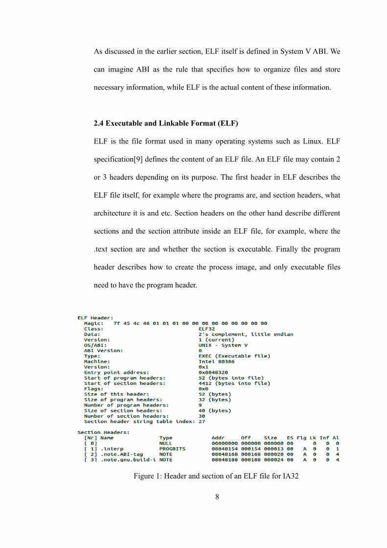
ELF is the file format used in many operating systems such as Linux. ELF
specification[9] defines the content of an ELF file. An ELF file may contain 2
or 3 headers depending on its purpose. The first header in ELF describes the
ELF file itself, for example where the programs are, and section headers, what
architecture it is and etc. Section headers on the other hand describe different
sections and the section attribute inside an ELF file, for example, where the
.text section are and whether the section is executable. Finally the program
header describes how to create the process image, and only executable files
need to have the program header.
Figure 1: Header and section of an ELF file for IA32
8
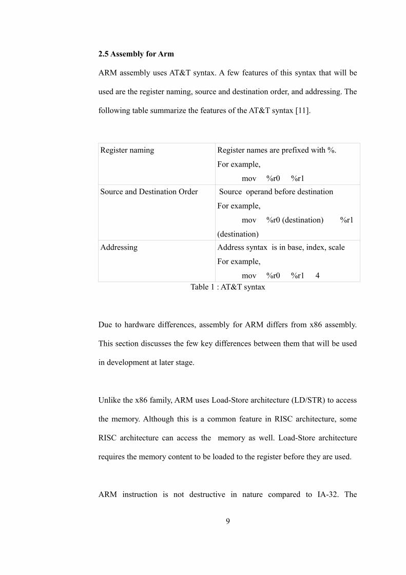
2.5 Assembly for Arm
ARM assembly uses AT&T syntax. A few features of this syntax that will be
used are the register naming, source and destination order, and addressing. The
following table summarize the features of the AT&T syntax [11].
Register naming Register names are prefixed with %.
For example,
mov %r0 %r1
Source and Destination Order Source operand before destination
For example,
mov %r0 (destination) %r1
(destination)
Addressing Address syntax is in base, index, scale
For example,
mov %r0 %r1 4Table 1 : AT&T syntax
Due to hardware differences, assembly for ARM differs from x86 assembly.
This section discusses the few key differences between them that will be used
in development at later stage.
Unlike the x86 family, ARM uses Load-Store architecture (LD/STR) to access
the memory. Although this is a common feature in RISC architecture, some
RISC architecture can access the memory as well. Load-Store architecture
requires the memory content to be loaded to the register before they are used.
ARM instruction is not destructive in nature compared to IA-32. The
9
following example illustrates the differences between the instructions for Add
operation.
To add 2 register,
In ARM:
add r0, r1, r2
add r1 and r2 and store the result in r0.
In IA-32:
mov cx, ax
add cx, bx
When adding bx to cx, the initial value for cx is destroyed.
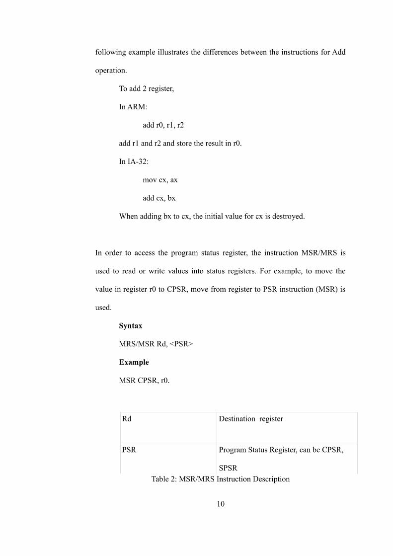
In order to access the program status register, the instruction MSR/MRS is
used to read or write values into status registers. For example, to move the
value in register r0 to CPSR, move from register to PSR instruction (MSR) is
used.
Syntax
MRS/MSR Rd, <PSR>
Example
MSR CPSR, r0.
Rd Destination register
PSR Program Status Register, can be CPSR,
SPSRTable 2: MSR/MRS Instruction Description
10
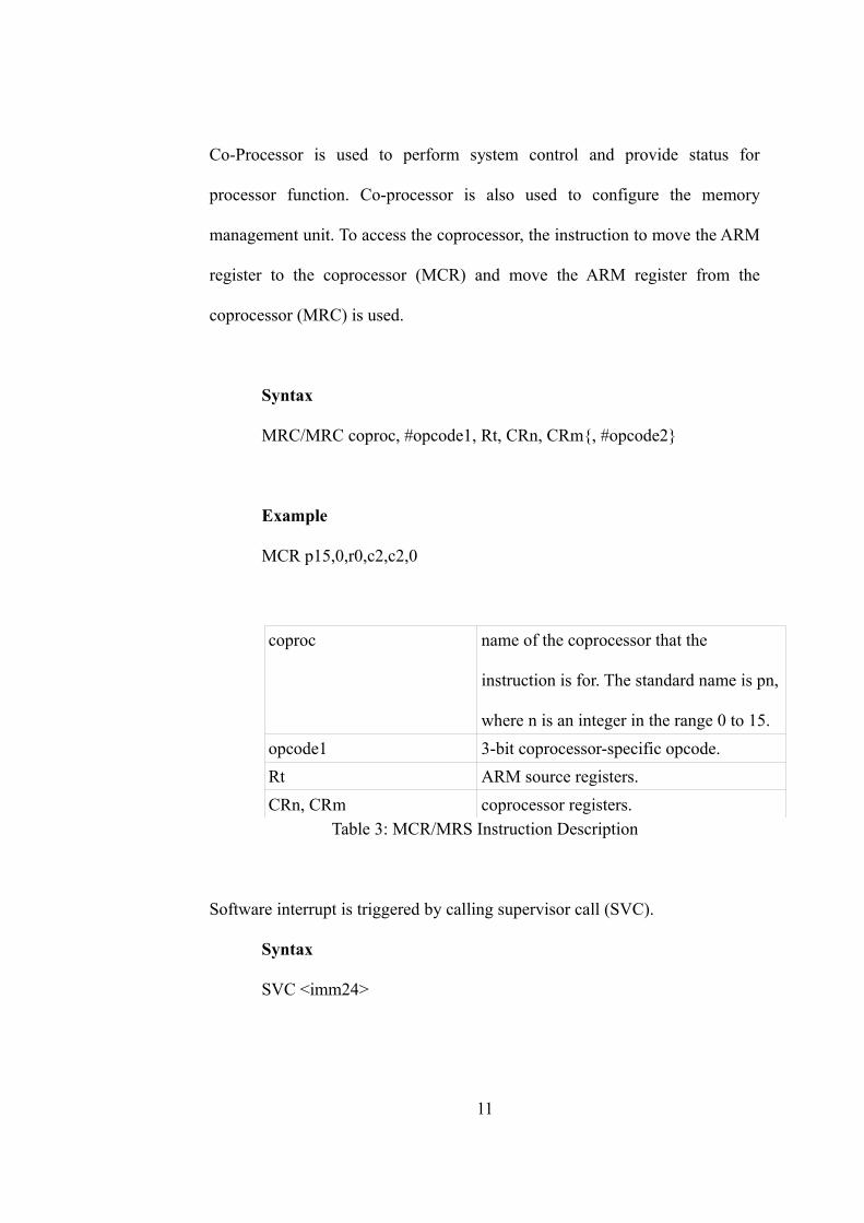
Co-Processor is used to perform system control and provide status for
processor function. Co-processor is also used to configure the memory
management unit. To access the coprocessor, the instruction to move the ARM
register to the coprocessor (MCR) and move the ARM register from the
coprocessor (MRC) is used.
Syntax
MRC/MRC coproc, #opcode1, Rt, CRn, CRm{, #opcode2}
Example
MCR p15,0,r0,c2,c2,0
coproc name of the coprocessor that the
instruction is for. The standard name is pn,
where n is an integer in the range 0 to 15.
opcode1 3-bit coprocessor-specific opcode.
Rt ARM source registers.
CRn, CRm coprocessor registers.Table 3: MCR/MRS Instruction Description
Software interrupt is triggered by calling supervisor call (SVC).
Syntax
SVC <imm24>
11
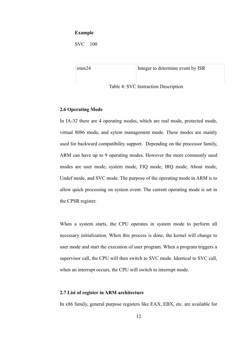
Example
SVC 100
imm24 Integer to determine event by ISR
Table 4: SVC Instraction Description
2.6 Operating Mode
In IA-32 there are 4 operating modes, which are real mode, protected mode,
virtual 8086 mode, and sytem management mode. These modes are mainly
used for backward compatibility support. Depending on the processor family,
ARM can have up to 9 operating modes. However the more commonly used
modes are user mode, system mode, FIQ mode, IRQ mode, About mode,
Undef mode, and SVC mode. The purpose of the operating mode in ARM is to
allow quick processing on system event. The current operating mode is set in
the CPSR register.
When a system starts, the CPU operates in system mode to perform all
necessary initialization. When this process is done, the kernel will change to
user mode and start the execution of user program. When a program triggers a
supervisor call, the CPU will then switch to SVC mode. Identical to SVC call,
when an interrupt occurs, the CPU will switch to interrupt mode.
2.7 List of register in ARM architecture
In x86 family, general purpose registers like EAX, EBX, etc. are available for
12
general usage such as calculation. ARM on the other hand has r0-r9 for the
same purpose with a large number of general registers to provide flexibility for
the programer to do coding.
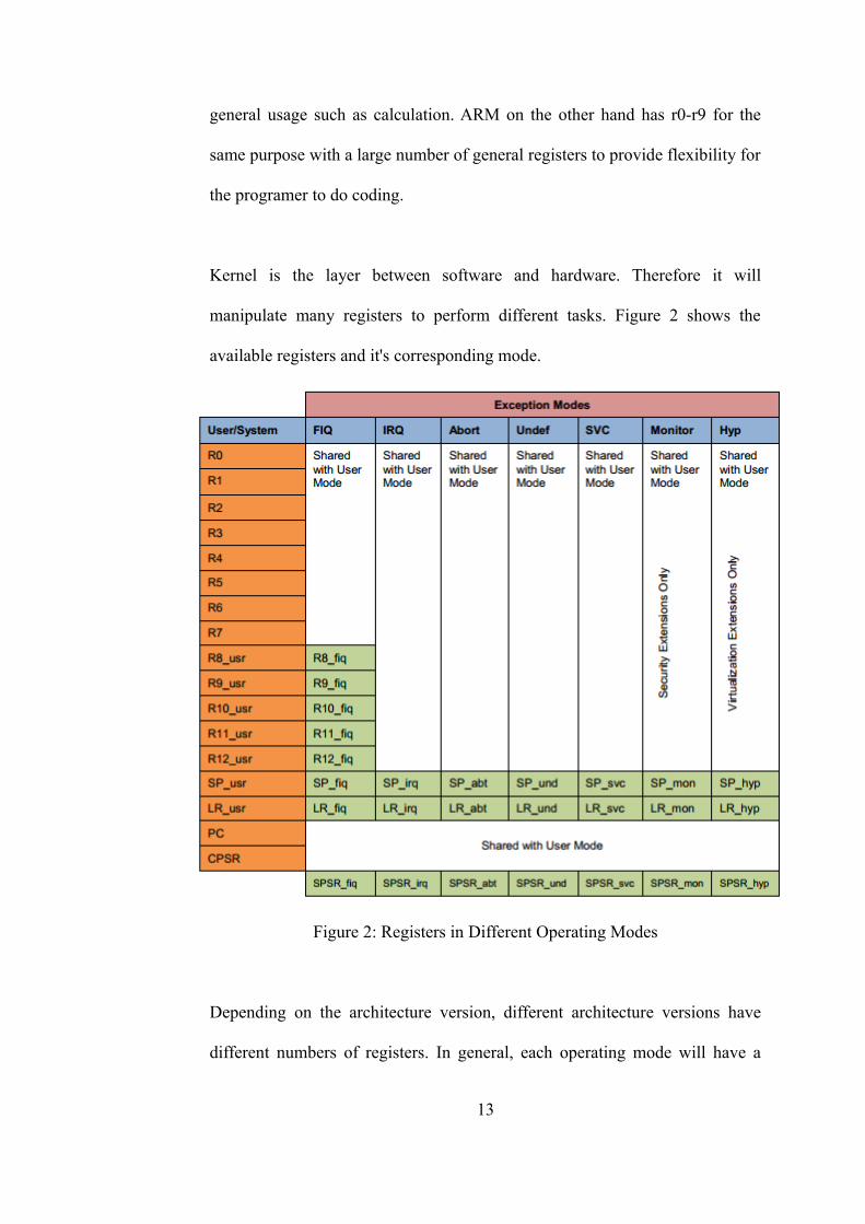
Kernel is the layer between software and hardware. Therefore it will
manipulate many registers to perform different tasks. Figure 2 shows the
available registers and it's corresponding mode.
Figure 2: Registers in Different Operating Modes
Depending on the architecture version, different architecture versions have
different numbers of registers. In general, each operating mode will have a
13

total of 16 registers. Out of these 16 registers, 13 of them can be used for
general purpose. R13 is commonly used as a stack pointer (as specified in
ARM ABI), R14 is the link register that holds the return address for a function
call, R15 is the program counter and R16 is the CPSR.
One of the most frequently used register is PSR. Different operating modes
can access different PSR registers. CPSR holds the state of a program whereby
multiple conditional flags are updated during instruction execution. Figure 3
describes the registers in CPSR and its corresponding function.
Figure 3: CPSR and SPSR register
Identical to CPSR, SPSR is responsible for storing the value in CPSR when
the CPU changes mode. The Kernel is responsible for restoring the value from
14
SPSR to CPSR when the system switches back from priviledge mode to non-
priviledge mode. SPSR is only available in privilege mode.
2.8 Endianess
ARM supports both endianess (little and big), where the E bit in CPSR is used
to support endianess. In general, ARM uses little endian in its asssembly
instructions. In most situations, the programmer does not have to care about
endianess apart from choosing the right tools and file format.
2.9 Kernel Functionality
The kernel is the core of the operating system that provides services to all
other programs. Depending on the operating system design, at minimal the
kernel has to provide I/O control and memory management. The main
functionalities in a modern kernel are I/O control, memory management,
process management and file management [14].
2.9.1 Type of kernel
There are 4 categories of kernel which are micorkernel, monolithic kernel,
hybrid kernel and exokernels. Two of the most widely used kernels are the
microkernel and monolithic kernel. The memory range that the kernel runs in
is called the kernel space, likewise the user program runs in user space. By
separating the memory space, the kernel can ensure that the user space
programs will not accidently break crucial kernel functions.
15
2.9.1.1 Micro kernel
Microkernel is a minimal kernel that only runs minimum services such as
memory and process management that allows an operating system to function.
Other functionalities such as I/O are implemented in the user space.
Microkernel has several advantages over other kernel design. It is highly
recoverable since only a few services are run in the kernel space, thus user
space programs can be restarted when there are problems. Another advantage
is that it is portable, whereby if the kernel needs to be ported to other
platforms, only a few services need to change.
2.9.1.2 Monolithic kernel
Monolithic kernel runs all the operating system services in the kernel space. It
manages all I/O, memory, process and etc. The advantage of monolithic kernel
is that it is faster, since every service is running in the same space. The main
disadvantage of a monolithic kernel is that it is not possible to recover if any
kernel service crashes. However operating systems such as Linux are very
stable and hardly crash due to reliable code and extensive testing.
2.10 Memory Map
Memory map provides the memory layout for memory, controller and
peripherals. In terms of differences between ia32 and ARM, ia32 consists of
IO instructions that enables it to read from IO directly, while ARM uses
memory map IO where all connected peripherals are mapped into a 4GB space
16
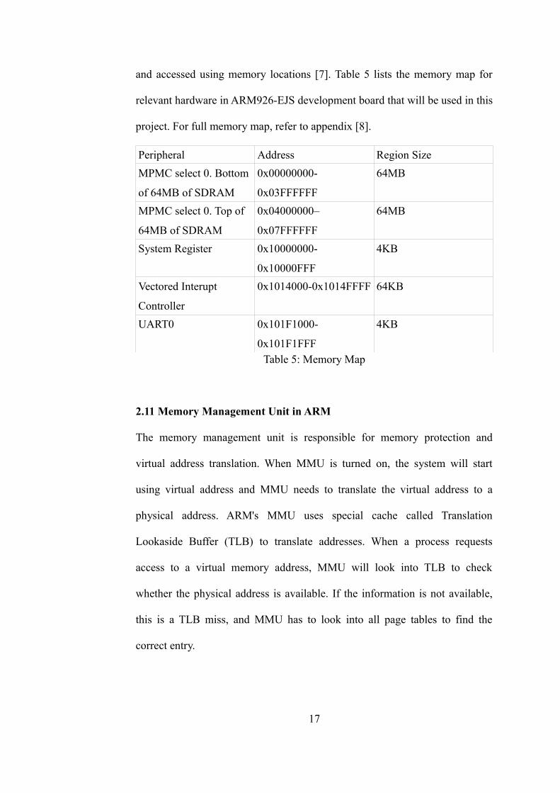
and accessed using memory locations [7]. Table 5 lists the memory map for
relevant hardware in ARM926-EJS development board that will be used in this
project. For full memory map, refer to appendix [8].
Peripheral Address Region Size
MPMC select 0. Bottom
of 64MB of SDRAM
0x00000000-
0x03FFFFFF
64MB
MPMC select 0. Top of
64MB of SDRAM
0x04000000–
0x07FFFFFF
64MB
System Register 0x10000000-
0x10000FFF
4KB
Vectored Interupt
Controller
0x1014000-0x1014FFFF 64KB
UART0 0x101F1000-
0x101F1FFF
4KB
Table 5: Memory Map
2.11 Memory Management Unit in ARM
The memory management unit is responsible for memory protection and
virtual address translation. When MMU is turned on, the system will start
using virtual address and MMU needs to translate the virtual address to a
physical address. ARM's MMU uses special cache called Translation
Lookaside Buffer (TLB) to translate addresses. When a process requests
access to a virtual memory address, MMU will look into TLB to check
whether the physical address is available. If the information is not available,
this is a TLB miss, and MMU has to look into all page tables to find the
correct entry.
17
There are different mapping schemes and the operating system may use a few
of them together. For example many to one mapping is a scheme where the
operating system maps multiple virtual address ranges to the same physical
memory adress. Flat address mapping on the other hand is the one to one
mapping where the virtual address is mapped directly to the physical address.
For the development board that is used in this project, a hardware MMU is
used to provide these functions. It is controlled by system control co-
processosr 15 (CP15). The MMU supports section (1MB), large page (64KB),
small page (4KB), and tiny page(1KB) mapping. Depending on the chosen
type, the size of Page Table Entries (PTE) will be very different in size. For
example if section is used, 4GB memory space is split into 4096 entries each
with 1MB block. If fine page is chosen then more entries is needed to
represent the entire 4GB space because memory is split into 1KB block.
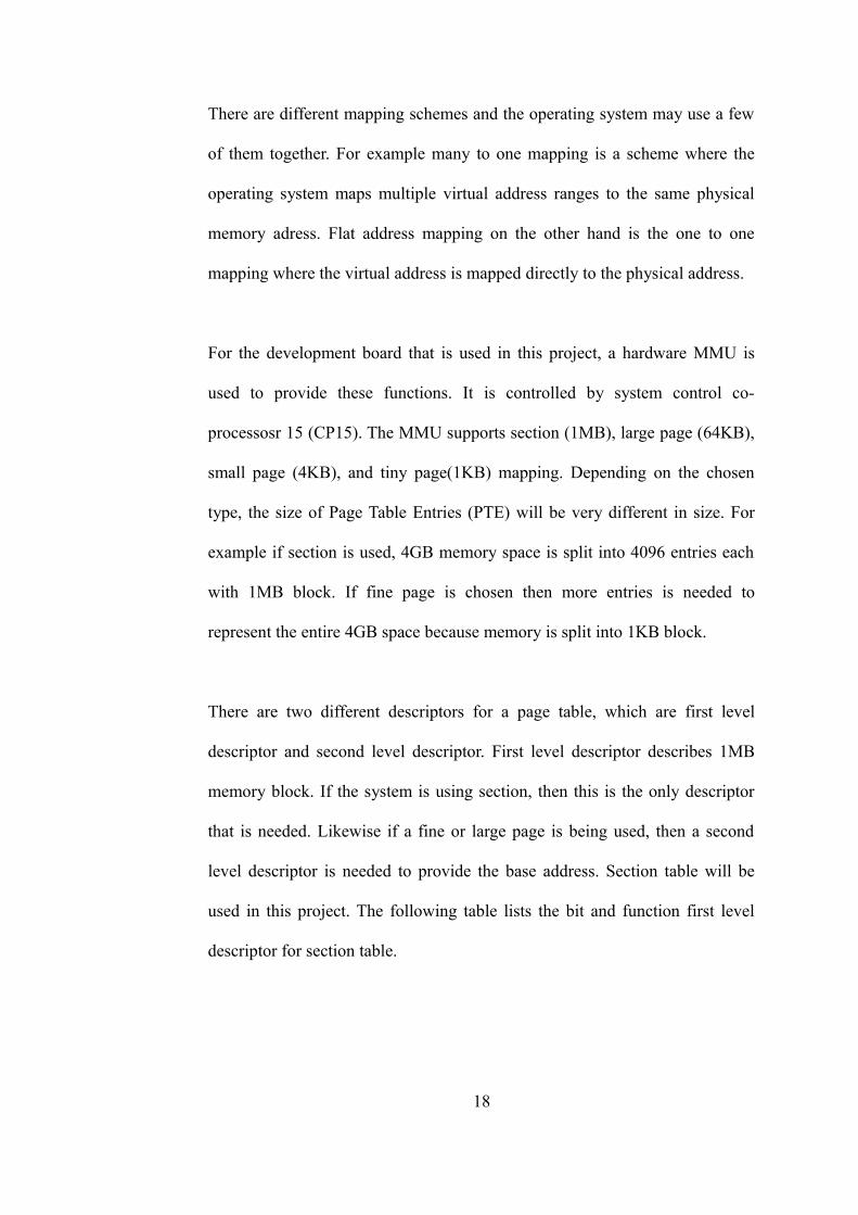
There are two different descriptors for a page table, which are first level
descriptor and second level descriptor. First level descriptor describes 1MB
memory block. If the system is using section, then this is the only descriptor
that is needed. Likewise if a fine or large page is being used, then a second
level descriptor is needed to provide the base address. Section table will be
used in this project. The following table lists the bit and function first level
descriptor for section table.
18
Bits Description
31:20 Corresponding bit in physical address
19:12 Should Be Zero
11:10 Access permission
9 Should Be Zero
8:5 Domain control bits
4 Must be 1
3:2 Cache control
1:0 Page Size, 0b10 indicate a section descriptorTable 6: Section Table Bit Description
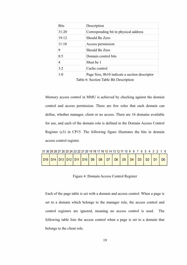
Memory access control in MMU is achieved by checking against the domain
control and access permission. There are few roles that each domain can
define, whether manager, client or no access. There are 16 domains available
for use, and each of the domain role is defined in the Domain Access Control
Register (c3) in CP15. The following figure illustrates the bits in domain
access control register.
Figure 4 :Domain Access Control Register
Each of the page table is set with a domain and access control. When a page is
set to a domain which belongs to the manager role, the access control and
control registers are ignored, meaning no access control is used. The
following table lists the access control when a page is set to a domain that
belongs to the client role.
19
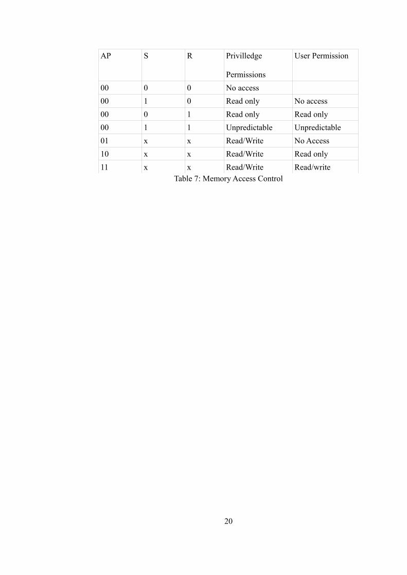
AP S R Privilledge
Permissions
User Permission
00 0 0 No access
00 1 0 Read only No access
00 0 1 Read only Read only
00 1 1 Unpredictable Unpredictable
01 x x Read/Write No Access
10 x x Read/Write Read only
11 x x Read/Write Read/writeTable 7: Memory Access Control
20
CHAPTER 3
3.0 TOOLS AND METHODOLOGY
3.1 Development methodology
This project is developed using the Scrum Agile software development
framework. Scrum is an iterative incremental development process that
embraces change. In Scrum, there are 3 major roles, which are the product
owner, scrum master, and team member. The product owner is the receiving
end of the project. In this project, the product owner is co-owned by the
project supervisor and the researcher. The product owner is responsible to
produce a list of expected outcomes and use cases (description of the system
behavior). The scrum master is the facilitator or project manager who acts as a
bridge between the product owner and team member. The scrum master's
responsibility is to remove impediments in the project and provide feedback
from both ends (the producer and receiver) of the project. The team member is
the development team involved in the actual development tasks such as
design, implementation, and testing. The following figure describes the scrum
process flow.
21
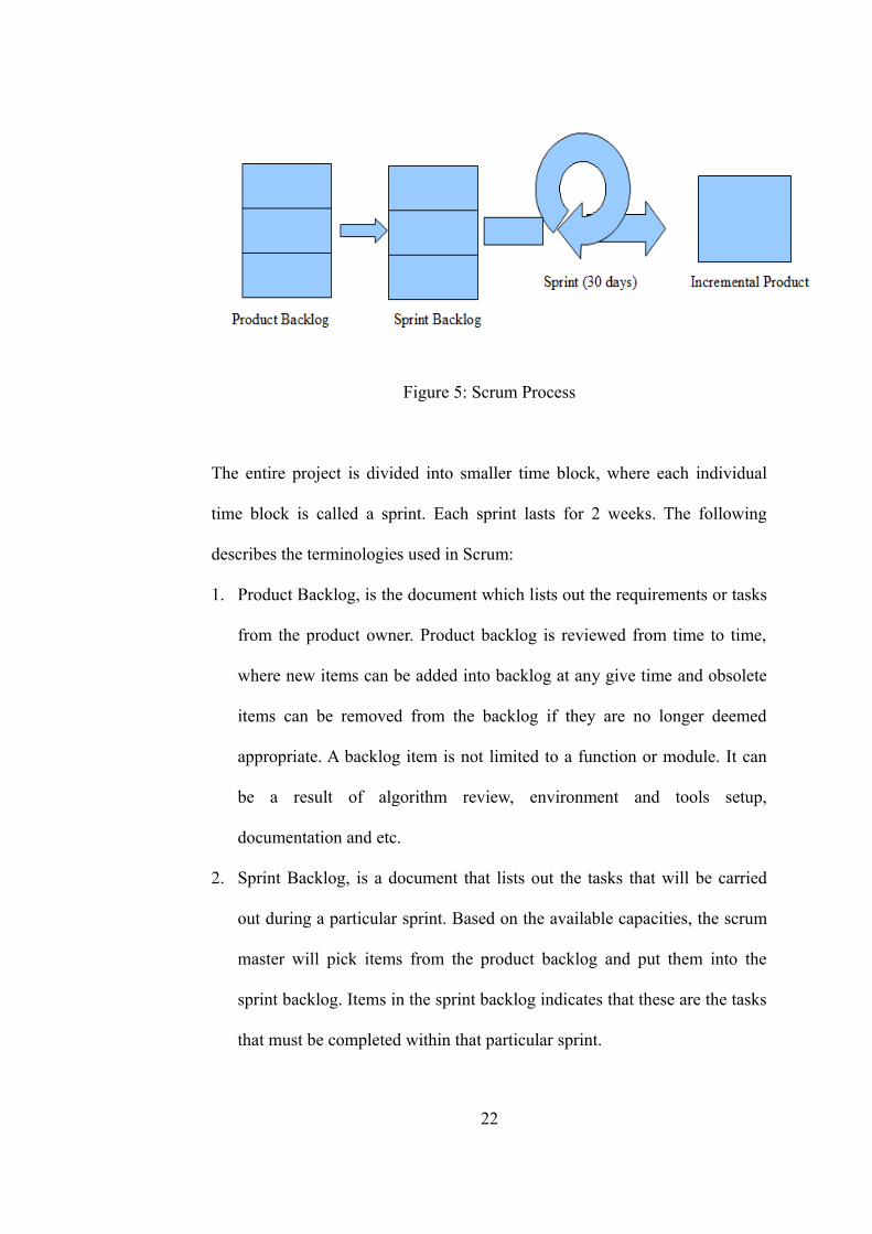
Figure 5: Scrum Process
The entire project is divided into smaller time block, where each individual
time block is called a sprint. Each sprint lasts for 2 weeks. The following
describes the terminologies used in Scrum:
1. Product Backlog, is the document which lists out the requirements or tasks
from the product owner. Product backlog is reviewed from time to time,
where new items can be added into backlog at any give time and obsolete
items can be removed from the backlog if they are no longer deemed
appropriate. A backlog item is not limited to a function or module. It can
be a result of algorithm review, environment and tools setup,
documentation and etc.
2. Sprint Backlog, is a document that lists out the tasks that will be carried
out during a particular sprint. Based on the available capacities, the scrum
master will pick items from the product backlog and put them into the
sprint backlog. Items in the sprint backlog indicates that these are the tasks
that must be completed within that particular sprint.
22
3. Sprint, is a short development cycle in which the team member has to
complete a task. A typical sprint involves both development task and
verification task (verify the outcome from the previous sprint). A sprint can
be abandoned if there is a change request, or extended if the sprint task
requires longer time than planned.
4. Incremental Product, is the outcome of the sprint. In Scrum methodology,
each sprint has to result in a product. This product is an incremental result
from the previous sprint and is also an indicator of the development progress.
3.2 Targeted ARM platform
The ARM9 processor is used for development in this project. The ARM9
family is using ARMv5 Architecture. The reason for selecting ARM9 is
because there are more resources available for it. However it will be discussed
in a later chapter on how to port over to other families using the information
available in this project.
3.3 Toolchain
Toolchain is the collection of tools that will turn code into binary executables.
The basic components of the toolchain are Binary Utility (binutils), compiler,
debugger and the C library. Toolchain can be used in native environment,
meaning compiled code is run on the same platform. It can also be used in
cross platform, for example compiling in x86 and running in ARM.
Toolchain is built together with the C library, therefore it is important to
23
determine which version of the library is needed, and select the proper
toolchain. There are a few C libraries available, which are glibc, eglibc, and
uClibC. The differences between these libraries are the C functionality and
size of the system. For example, if full C functionality is needed then the
toolchain has to be built with glibc. On the other hand, if a smaller system is
desirable, then developer can choose a toolchain that uses uClibC.
Embedded Linux Development Kit (ELDK) is the cross development tools
that is used in this project. ELDK is built with a fully functional C library
(glibc) and supports multiple different architectures. In this project, ELDK that
supports ARMv5 is used. ELDK that supports older ARM family can be used
as well, since the ARM toolchain is backward compatibile. However by doing
so the toolchain will not utilise the new ARM feature that is available in newer
architecture families.
3.4 Emulator
There are a few available options to test the generated kernel binary The most
straighforward is to boot the code directly from a development board.
However, this option is inconvenient as the system needs to be rebooted often
in order to test the code. Also another disadvantage is that the debugging is
more difficult as it will require hooking to physical hardware such as jtag to do
debugging.
Another way to test the code is to use the virtualization tool in the
24
develpoment board. Virtualization allows the user to run their kernel within
another operating system. Newer hardware that supports virtualization allows
the virtual environment to run in near native speed. The only problem with this
method is that quite often when developing in low power embedded
development boards, running one system in another system might lack
sufficient resources such as storage and memory.
Finally, another option to test the code is to use an emulator. Emulator is a
program that emulates the targeted platform. For example an ARM emulator is
a program that runs in x86 environment that mimics the behavior of the an
actual ARM system. The advantage of this method is that the development and
debugging is easy, however, some of the hardware features might not be fully
supported.
There are many available emulators, such as bochs and qemu. In this project,
the QEMU emulator is used since it supports the targeted ARM platform that
was chosen. QEMU emulator is available in 2 different modes, which are the
user space mode and kernel mode. When a program is compiled with the ARM
toolchain, the user space mode can be used to execute it. However when
developing a kernel, the kernel mode has to be used, which acts as the actual
hardware.
When QEMU is run to mimic the hardware, it will start the execution at
address 0x10000. Therefore, any startup code has to be available in this
25
location. It is the kernel's responsibility to then copy and move necessary code
to different addresses based on the system design. The user can terminate
QEMU (ctrl a + x) at any time and it will not affect the host system. This is the
benefit of using an emulator.
As mentioned earlier, another benefit of using QEMU is for debugging. When
starting the emulator the option can be passed in to connect the debug
information to a tcp port and wait for a debugger to connect to it before it runs.
Emulator will pass all the hardware information such as register value to the
debugger.
3.5 Linker/ Linker Script
The Linker is a tool that is responsible for combining multiple binary files into
a single executable. Before a linker can generate an executable file, it needs
information to organize the binary. This can be done by passing in options
when invoking the linker. This approach is inconvenient as the same step has
to be repeated many times. Thus, a linker script can be written to tell the
linker how it should map input file to output file.
Each executable program should consist of code, the initialised and
uninitialised data. At bare minimum, the linker script must have a SECTIONS
command. This command tells the linker how the memory layout of the output
file should be. It gives information such as which address the code should
load into and where to put the code (.text), initialise data (.data) and
26
uninitialise data (.bss).
An example of linker script:
SECTIONS
{
. = 0x10000;
}
The linker script can be very complex to include many other aspects on how to
link a file. For example, specifying which memory region the linker should
allocate from, or how to specify a program header in ELF. If the user did not
specify any of these, then the linker will use the default rule to generate the
output binary.
Table 8 summarizes the symbols that are used in this project.
Symbol Description
Location counter (.) The current location counter
Wildcard (*) Match any of the characterTable 8: linker script symbol and description
3.6 GNU Compiler Collection (GCC)
One of the main component of any toolchain is GCC. It can compile code
from supported languages and generate executable binary files. Although GCC
is used for C language most of the time, it supports multiple languages and has
been ported to many architectures. There are many kinds of usage of GCC, for
27
example, if the developer is interested to see the assembly file that is generated
by GCC, they can configure the GCC to do so.
Some useful options in this project:
-g add debugging information for gdb
3.7 GNU Project Debugger (GDB)
When developing any software, debugging is as important as compiling as the
programmer needs to figure out what went wrong with the program. GDB is
part of the ELDK toolchain that allows the programmer to debug their system.
Like all other debuggers, GDB allows the user to set break points, step in code
and etc. GDB also allows the user to inspect the content of memory and
registers.
The following are some usage of GDB relevant to this project
info registers – Displays the value of CPSR
print -
x – Examine content of memory location
s – step through code
3.8 Bootloader
Bootloader is one component of a system that is used only during system
startup and is yet extremely important. When a system starts up, the operating
system is stored in some storage and it is the responsibility of a bootloader to
28
load them into the memory .
For PC, the BIOS is responsible for loading the operating system into the
memory for execution. ARM on the other hand, starts up the bootloader from
the ROM (build by the vendor). The bootloader is in charge of setting up the
memory and intializing hardware. Once the initialization is completed, the
bootloader will pass the control to the kernel. If the kernel supports device
tree, the bootloader will pass a device tree binary to the kernel so that the
kernel can initialize the driver when a system starts. A device tree is a data
structure for describing the hardware in a system.
ARM is a popular architecture that is supported by many bootloaders. An
example of an open source bootloader is the Das U-Boot by DENX. U-Boot
provides a list of command line tools that allows the user to manage boot task.
For example, the user can choose to boot from netwok, or load file from the
filesystem.
3.9 Automating Build Process
Due to the complexity of kernel development, a lot of trial and error
experiments are required. Therefore, to speed up the process, it is necessary to
automate some build processes. Make is one of the commonly used build tool
in development including famous operating systems such as Linux and Minix.
Make uses a configuration file to automate the build process. This
29
configuration file is usually called Makefile, and contains a list of required
steps that the user defines. For example a user that creates multiple steps that
are interdependent. When Make tries to execute one of them, it will first go
though the steps which are needed and runs them before executing the targeted
step.
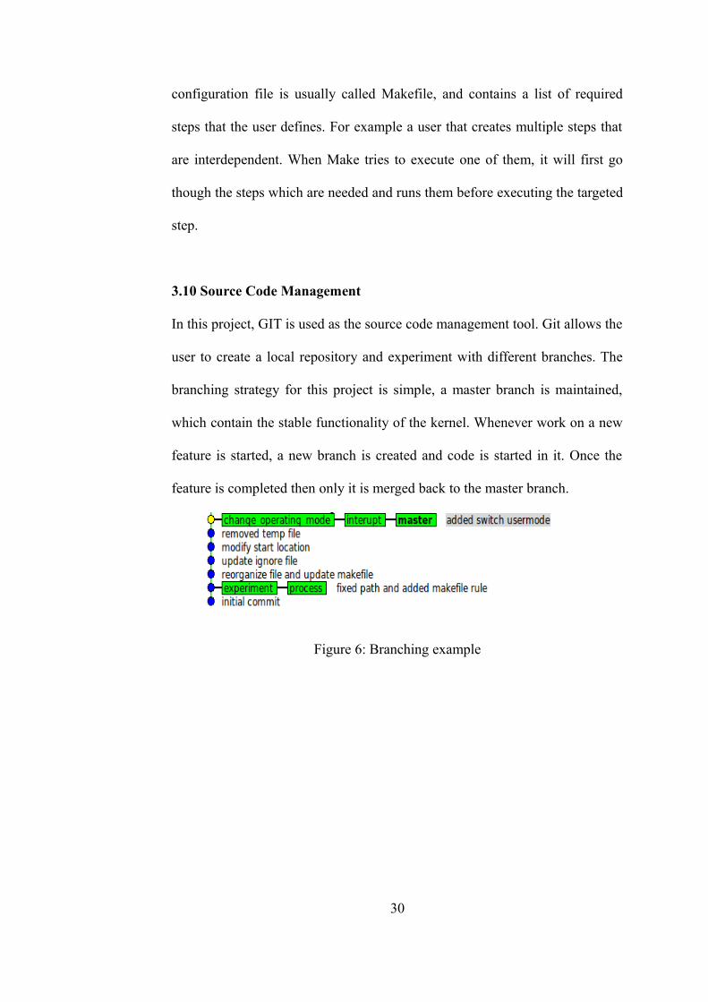
3.10 Source Code Management
In this project, GIT is used as the source code management tool. Git allows the
user to create a local repository and experiment with different branches. The
branching strategy for this project is simple, a master branch is maintained,
which contain the stable functionality of the kernel. Whenever work on a new
feature is started, a new branch is created and code is started in it. Once the
feature is completed then only it is merged back to the master branch.
Figure 6: Branching example
30
CHAPTER 4
4.0 DESIGN AND SPECIFICATION
4.1 System Environment
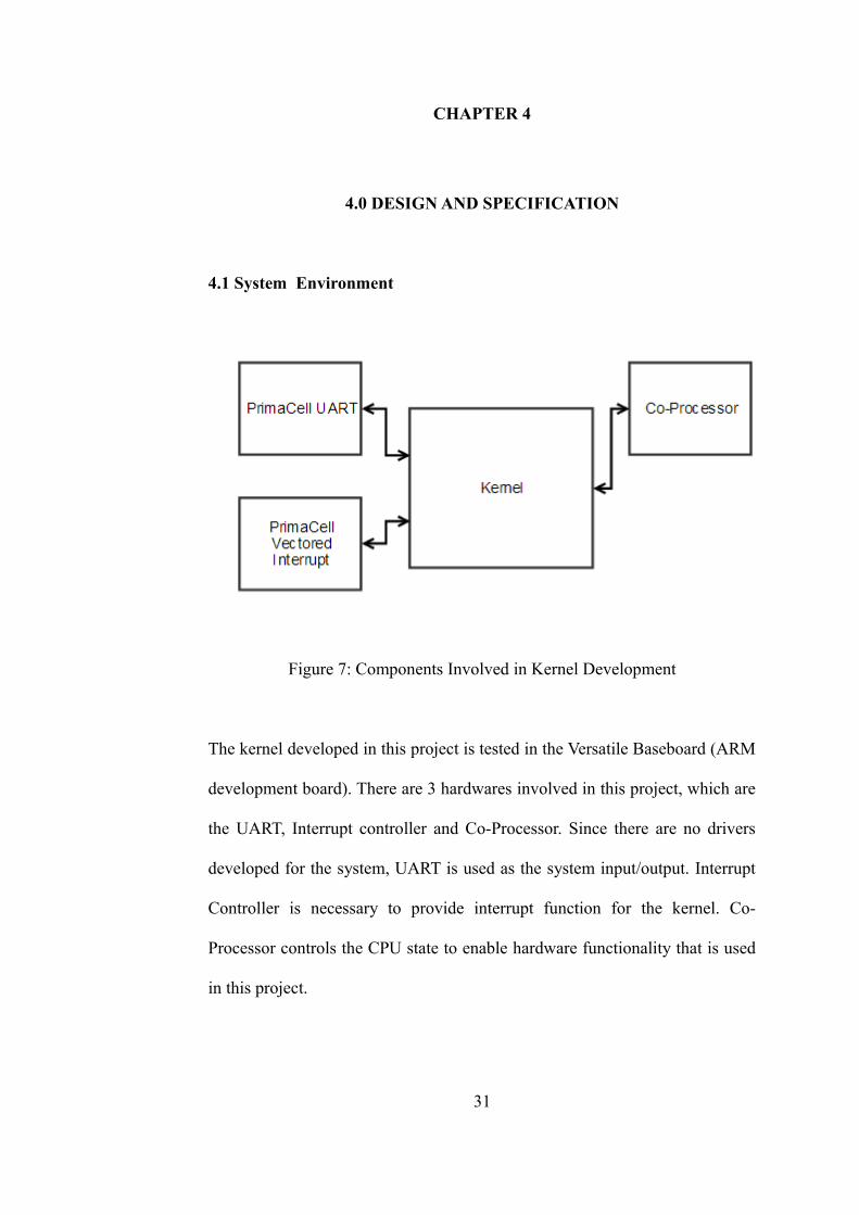
Figure 7: Components Involved in Kernel Development
The kernel developed in this project is tested in the Versatile Baseboard (ARM
development board). There are 3 hardwares involved in this project, which are
the UART, Interrupt controller and Co-Processor. Since there are no drivers
developed for the system, UART is used as the system input/output. Interrupt
Controller is necessary to provide interrupt function for the kernel. Co-
Processor controls the CPU state to enable hardware functionality that is used
in this project.
31
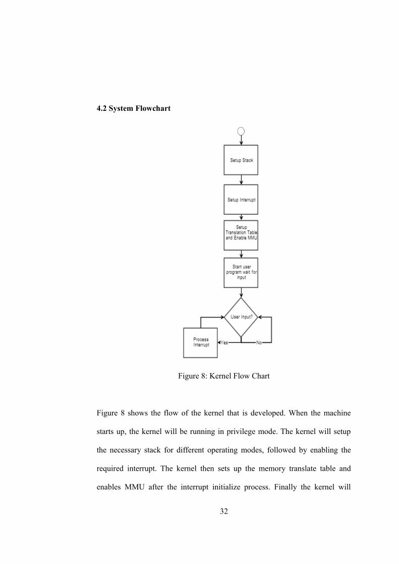
4.2 System Flowchart
Figure 8: Kernel Flow Chart
Figure 8 shows the flow of the kernel that is developed. When the machine
starts up, the kernel will be running in privilege mode. The kernel will setup
the necessary stack for different operating modes, followed by enabling the
required interrupt. The kernel then sets up the memory translate table and
enables MMU after the interrupt initialize process. Finally the kernel will
32
switch into user mode and wait for user input.
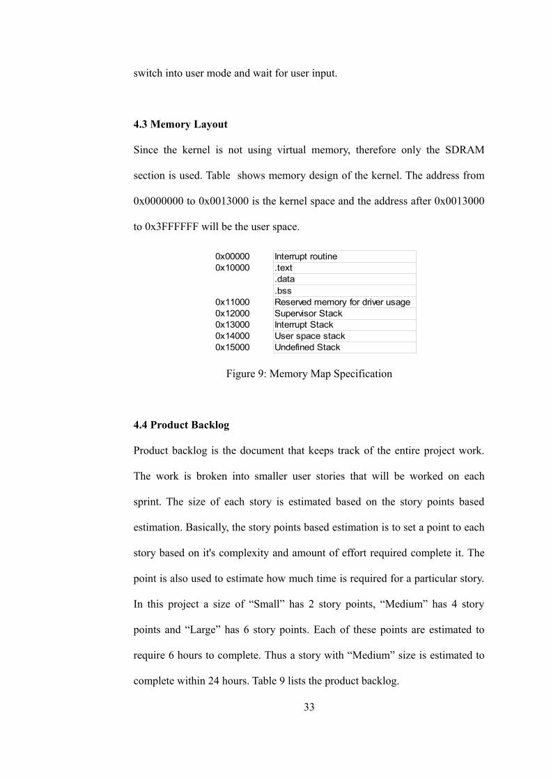
4.3 Memory Layout
Since the kernel is not using virtual memory, therefore only the SDRAM
section is used. Table shows memory design of the kernel. The address from
0x0000000 to 0x0013000 is the kernel space and the address after 0x0013000
to 0x3FFFFFF will be the user space.
Figure 9: Memory Map Specification
4.4 Product Backlog
Product backlog is the document that keeps track of the entire project work.
The work is broken into smaller user stories that will be worked on each
sprint. The size of each story is estimated based on the story points based
estimation. Basically, the story points based estimation is to set a point to each
story based on it's complexity and amount of effort required complete it. The
point is also used to estimate how much time is required for a particular story.
In this project a size of “Small” has 2 story points, “Medium” has 4 story
points and “Large” has 6 story points. Each of these points are estimated to
require 6 hours to complete. Thus a story with “Medium” size is estimated to
complete within 24 hours. Table 9 lists the product backlog.
33
0x00000 Interrupt routine 0x10000 .text
.data
.bss0x11000 Reserved memory for driver usage 0x12000 Supervisor Stack0x13000 Interrupt Stack0x14000 User space stack0x15000 Undefined Stack
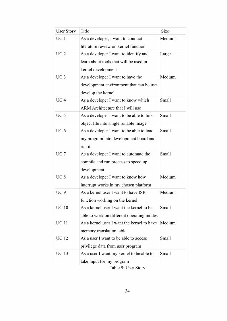
User Story Title Size
UC 1 As a developer, I want to conduct
literature review on kernel function
Medium
UC 2 As a developer I want to identify and
learn about tools that will be used in
kernel development
Large
UC 3 As a developer I want to have the
development environment that can be use
develop the kernel
Medium
UC 4 As a developer I want to know which
ARM Architecture that I will use
Small
UC 5 As a developer I want to be able to link
object file into single runable image
Small
UC 6 As a developer I want to be able to load
my program into development board and
run it
Small
UC 7 As a developer I want to automate the
compile and run process to speed up
development
Small
UC 8 As a developer I want to know how
interrupt works in my chosen platform
Medium
UC 9 As a kernel user I want to have ISR
function working on the kernel
Medium
UC 10 As a kernel user I want the kernel to be
able to work on different operating modes
Small
UC 11 As a kernel user I want the kernel to have
memory translation table
Medium
UC 12 As a user I want to be able to access
privilege data from user program
Small
UC 13 As a user I want my kernel to be able to
take input for my program
Small
Table 9: User Story
34
4.4.1 Functional Requirement Specification
User Story 1: As a developer, I want to conduct literature review on kernel
function
Brief Description
The study on different types of kernel, how kernel works in different
environment and kernel functionality
Acceptance Criteria
1. Understand and document the differences between kernel
2. Define and create the specification for kernel development
User Story 2: As a developer I want to identify and learn about tools that will
be used in kernel development
Brief Description
Research on the available tools to develop the kernel and learn how to use
them
Acceptance Criteria
1. Identify the toolchain that will be used this project
2. Identify the emulator/simulator that will be use in this project
3. Identify the suitable development environment
User Story 3: As a developer I want to have a suitable development
environment that can be used develop the kernel
Brief Description
Setting up a development environment that can be used to develop ARM code
35
Acceptance Criteria
1. Able to compile and link a program for ARM
2. Able to debug a program and register state
User Story 4: As a developer I want to know which ARM Architecture that I
will use
Brief Description
Identify the architecture that will be used in this project
Acceptance Criteria
1. Understand and document ARM processor family
2. The targeted development board is chosen
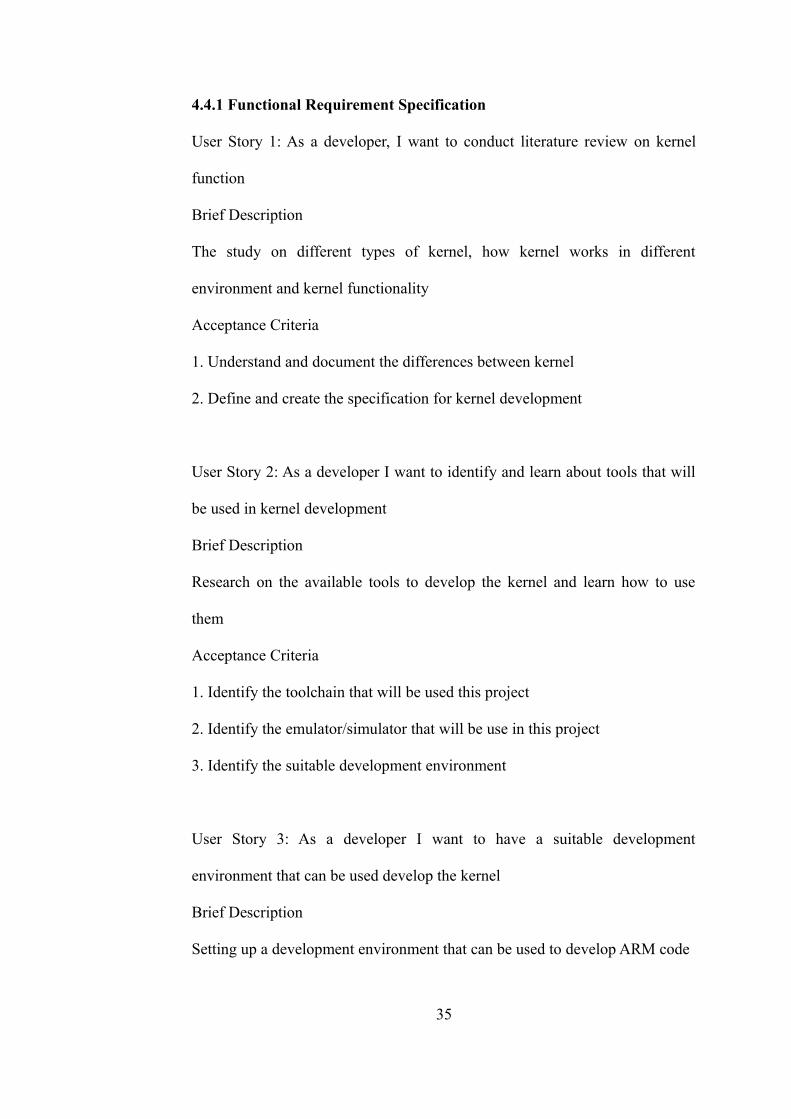
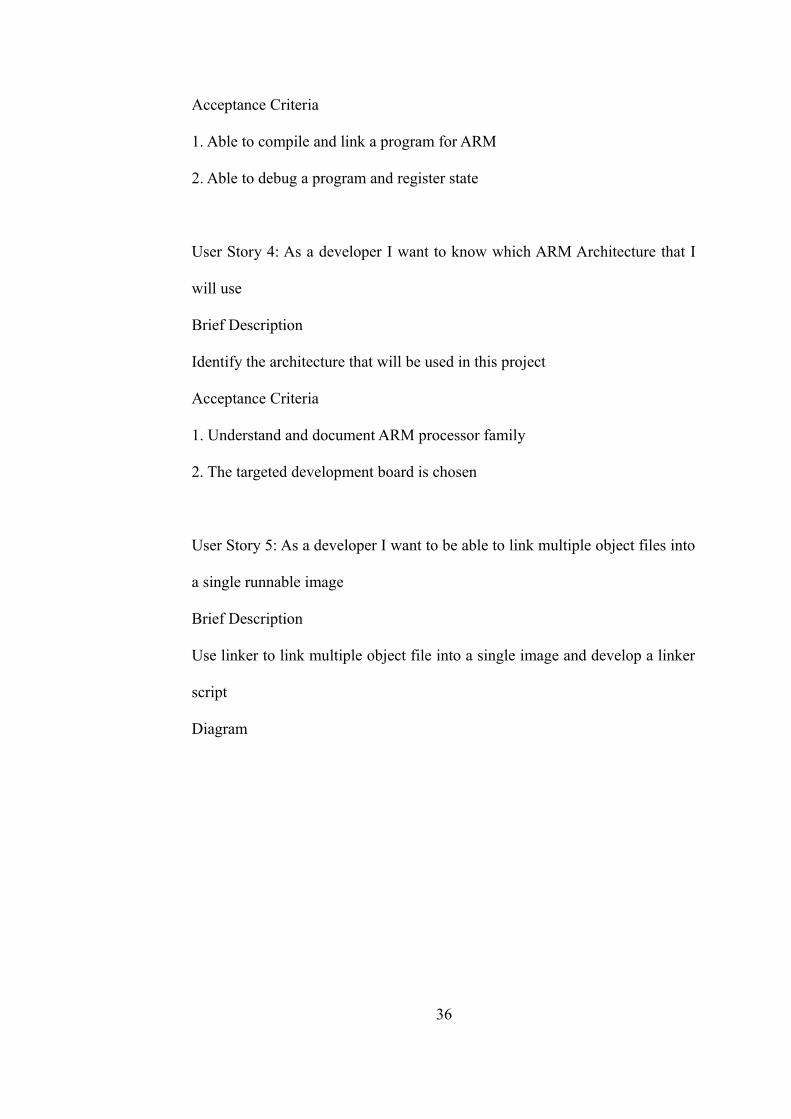
User Story 5: As a developer I want to be able to link multiple object files into
a single runnable image
Brief Description
Use linker to link multiple object file into a single image and develop a linker
script
Diagram
36
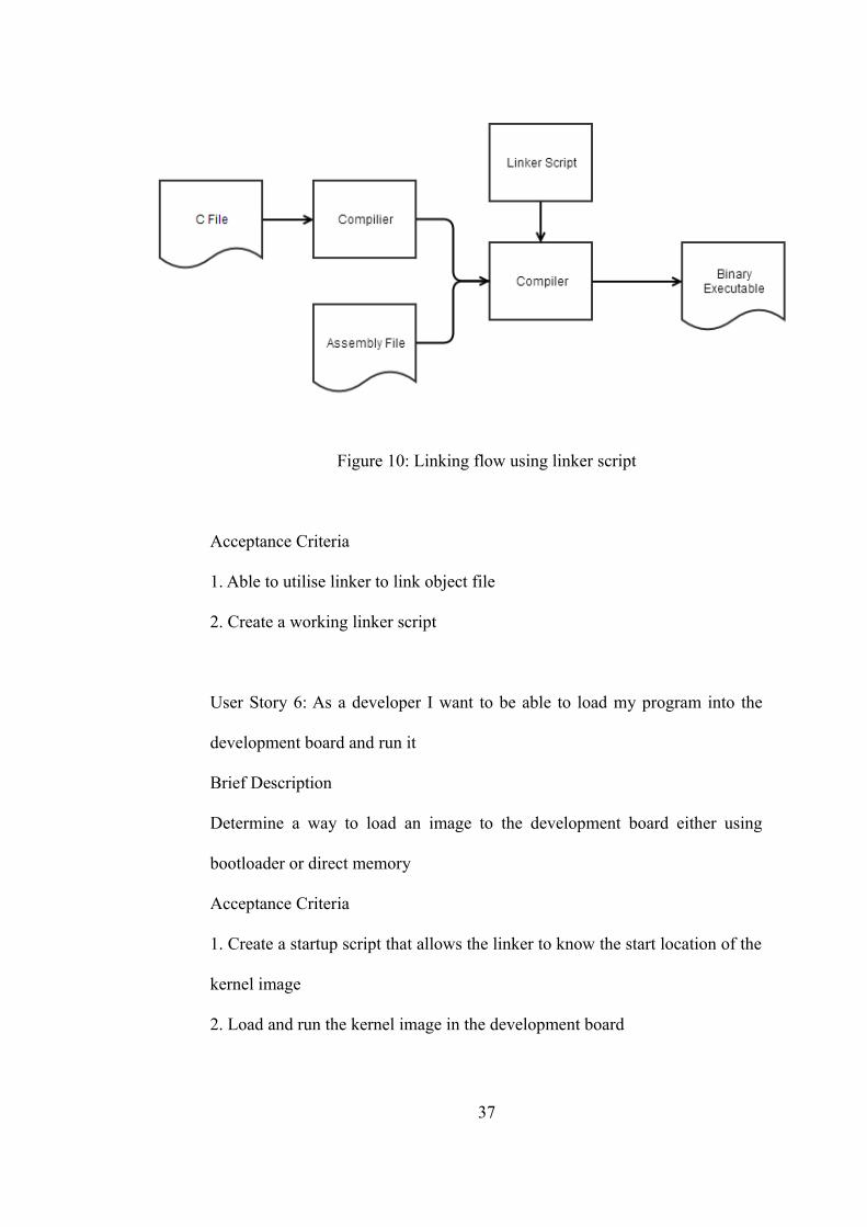
Figure 10: Linking flow using linker script
Acceptance Criteria
1. Able to utilise linker to link object file
2. Create a working linker script
User Story 6: As a developer I want to be able to load my program into the
development board and run it
Brief Description
Determine a way to load an image to the development board either using
bootloader or direct memory
Acceptance Criteria
1. Create a startup script that allows the linker to know the start location of the
kernel image
2. Load and run the kernel image in the development board
37
User Story 7: As a developer I want to automate the compile and run process
to speed up development
Brief Description
Utilise makefile to simplify compile and run process
Acceptance Criteria
1. Develop a working makefile that is able to compile, link, run and clean up
project file
Story Size
User Story 8: As a developer I want to know how interrupt works on my
chosen platform
Brief Description
Study the interrupt controller on the targeted platform
Acceptance Criteria
1. How the interrupt controller works in the targeted platform is identified &
documented
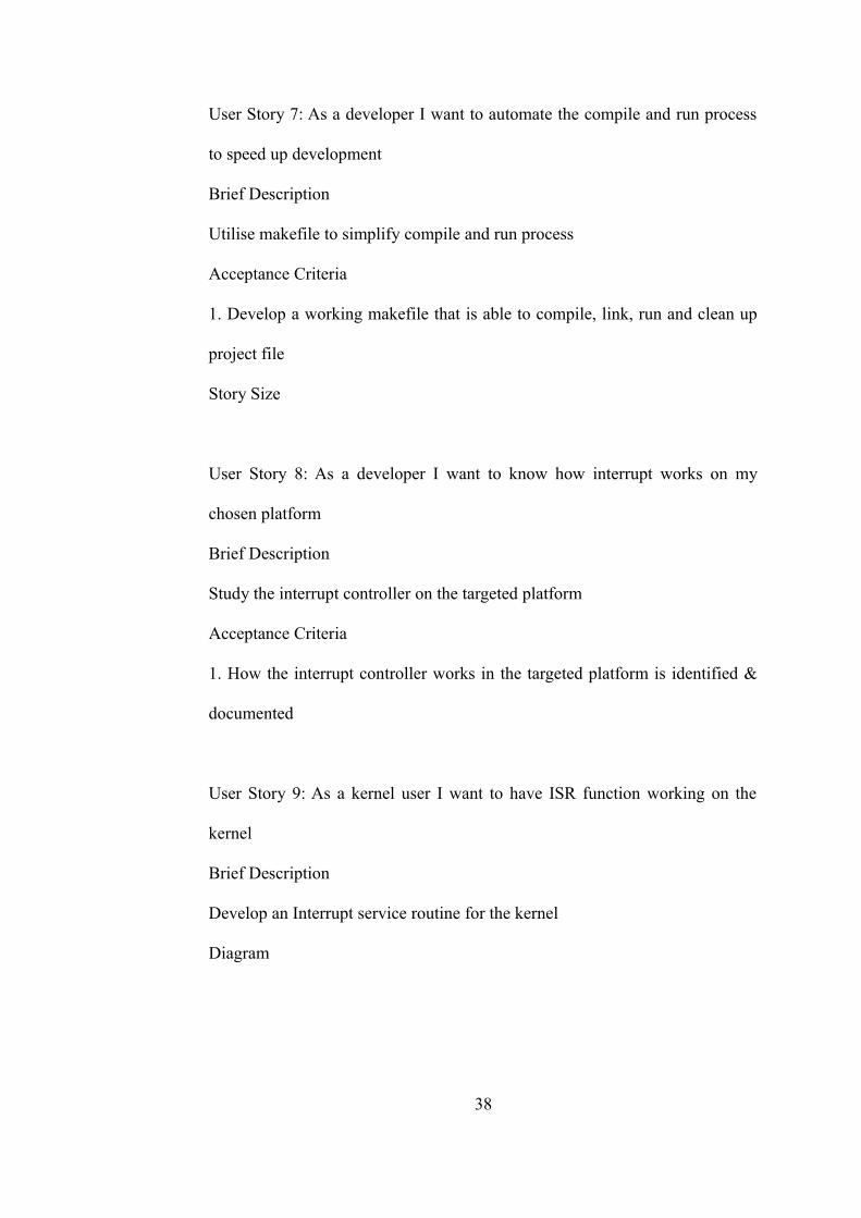
User Story 9: As a kernel user I want to have ISR function working on the
kernel
Brief Description
Develop an Interrupt service routine for the kernel
Diagram
38
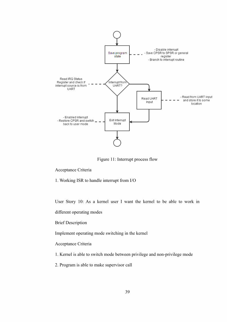
Figure 11: Interrupt process flow
Acceptance Criteria
1. Working ISR to handle interrupt from I/O
User Story 10: As a kernel user I want the kernel to be able to work in
different operating modes
Brief Description
Implement operating mode switching in the kernel
Acceptance Criteria
1. Kernel is able to switch mode between privilege and non-privilege mode
2. Program is able to make supervisor call
39
User Story 11: As a kernel user I want the kernel to have memory translation
table
Brief Description
Implement memory translation table and enable basic memory management
Diagram
Figure 12: Memory Management Flow
Acceptance Criteria
1. Memory translation table is setup
2. Memory management unit is turned on
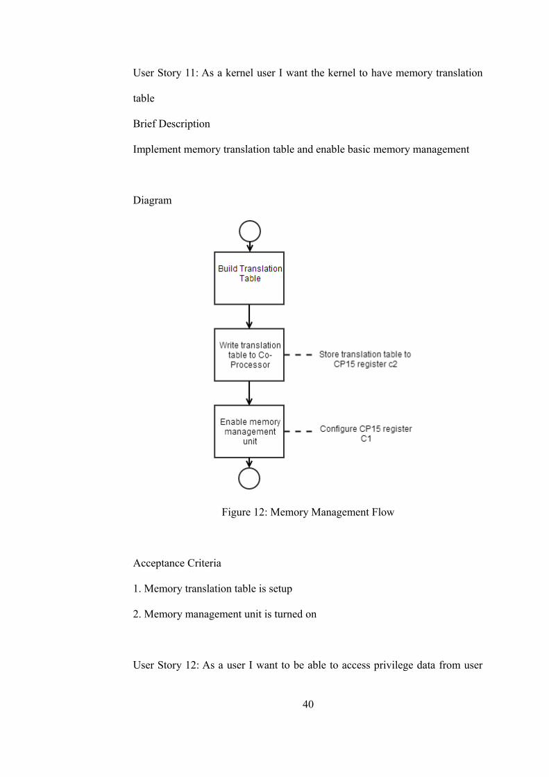
User Story 12: As a user I want to be able to access privilege data from user
40
program
Brief Descriptiom
Program in user mode is able to access privilege function such as I/O
Diagram
Figure 13: Operating Mode Flow
Acceptence Criteria
1. Kernel exposes hardware capability via function call
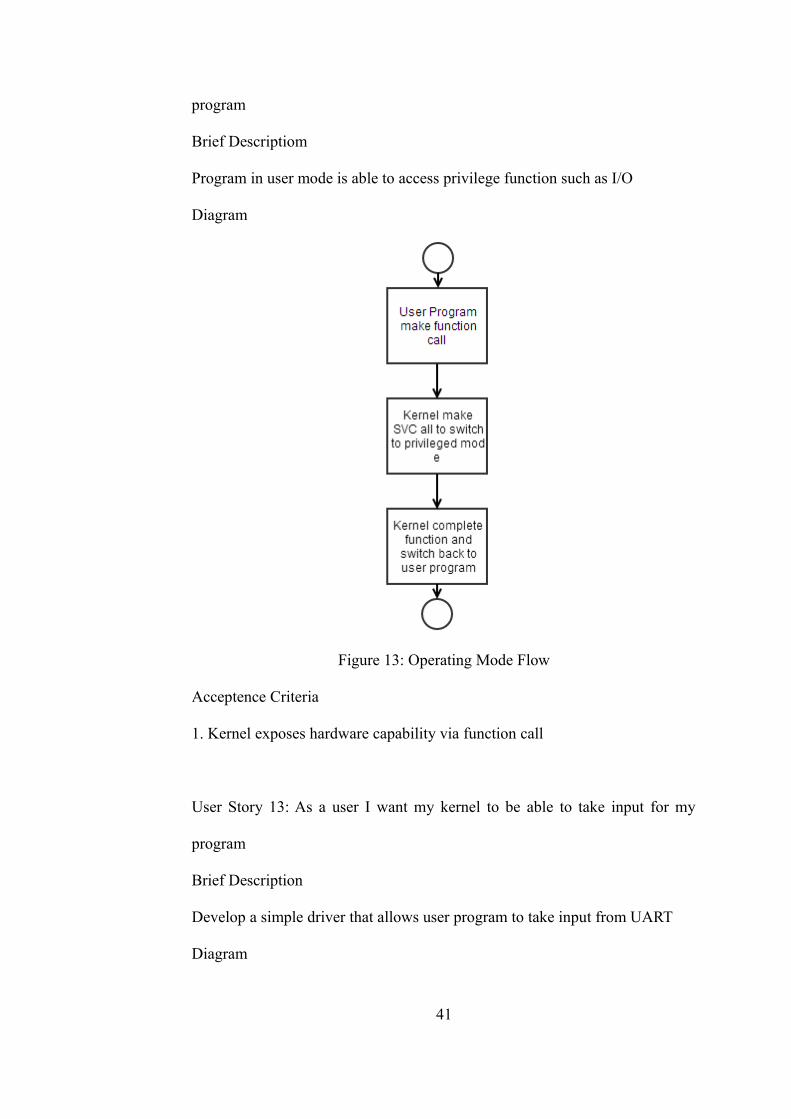
User Story 13: As a user I want my kernel to be able to take input for my
program
Brief Description
Develop a simple driver that allows user program to take input from UART
Diagram
41
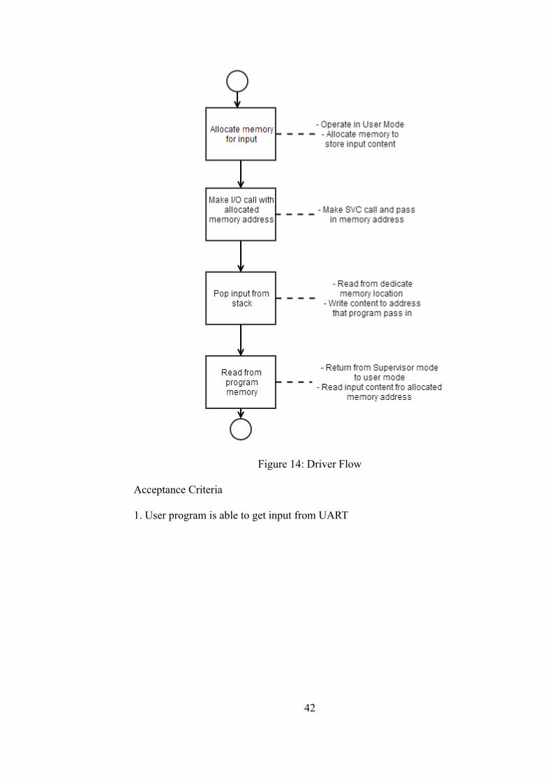
Figure 14: Driver Flow
Acceptance Criteria
1. User program is able to get input from UART
42
CHAPTER 5
5.0 IMPLEMENTATION
Unlike other software development methods, in Scrum, each sprint has it's
own working deliverable. The deliverable is not neccessay a working piece of
code, for example a document is the deliverable of a research story. In this
project, UC 1 ,UC 2, UC 4 and UC 8 are the research stories and it's
deliverables are part of this report, thus there are no testing involved.
5.1 Development environment (User Story 3)
The kernel is developed in Ubuntu environment, Ubuntu is an open source
Debian based Linux distribution that is free to use. The reason why Ubuntu is
chosen is mainly because it is supported by the chosen toolchain (ELDK).
Apart from that, it has a package management system that allows the user to
conveniently get packages or software libraries that work together. It also has
more applications and commands that are helpful in development.
5.1.1 Setting up toolchain
ELDK supports many different architectures, therefore it is important to
download the proper tool. The targeted architecture should be ARMv5TE
since the ARM9 processor is used. The following steps summarize the
installation process:
1. Download iso image for ARMv5TE architecture from
43
ftp://ftp.denx.de/pub/eldk/5.5/iso/ and mount it to operating system.
2. Verify the downloaded image has correct checksum
3. Run installation script and setup environment script when installation is
completed.
5.2 Linking option and script (User Story 5)
Accordingly to the system requirement, the kernel will be put to the address
0x10000 and the entry function is to initialize the kernel. Thus, the linker is set
to start the program at address 0x10000 and entry function reset_handler.
reset_handler is the function that is invoked during startup to setup interrupt
and etc.
In order for the kernel to work, it is necessary to link all functions into a
single binary. The following command is used to link all the function binary to
kernel image.
arm-linux-gnueabi-ld -e main -Ttext 0x10000 -o kernelImage
out/*.o
It is impractical to enter all the function, so, to simplify the process, a linker
script is created to pass in the same information to the linker. The following
code provides the same information as the command line option that is
specified during linking.
ENTRY(RESET_HANDLER)
SECTIONS
{
. = 0x10000;
.text : {
out/startup.o
44
*(.text)
}
.data : { *(.data) }
.bss : { *(.bss) }
. = ALIGN(8);
stack_top = 0x12000;
...
}
5.3 System Startup Script (User Story 6)
Although the goal of the project is to use C language in coding, there are some
functions that are easier to implement using assembly. In this project, the
startup script is coded in assembly language. It is responsible for initializing
the system, for example, setting up stack and enabling interrupt.
The kernel memory map requirement specifies the address for program stack
in different modes. These stack will be setup during the execution of the start
up script, the system will need to switch to different mode and set the register
SP to its designated location.
One of the main reasons to set up stack in all the operating modes that will be
used is to allow function call. When a function call is made, the assembler has
to generate necessary code to prepare the register and stack. The code that is
appended to the beginning of the function is the function prologue and code
that is appended to the end of the function is the function epilogue. ARM
Procedure Call Standard [12] is a document that describes the procedure call
as specified in EABI. EABI also specifies the function prologue and epilogue
that will be added to the function. Table 10 shows the registers convention that
is used in APCS.
45
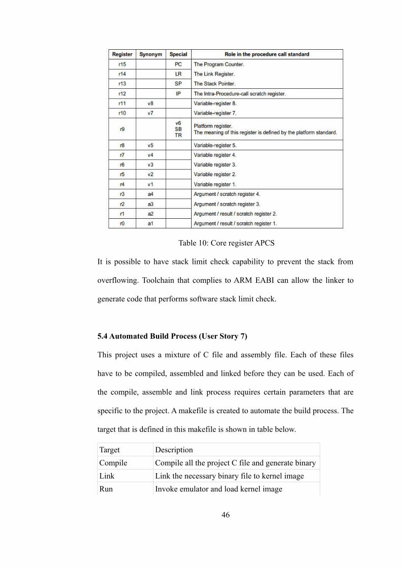
Table 10: Core register APCS
It is possible to have stack limit check capability to prevent the stack from
overflowing. Toolchain that complies to ARM EABI can allow the linker to
generate code that performs software stack limit check.
5.4 Automated Build Process (User Story 7)
This project uses a mixture of C file and assembly file. Each of these files
have to be compiled, assembled and linked before they can be used. Each of
the compile, assemble and link process requires certain parameters that are
specific to the project. A makefile is created to automate the build process. The
target that is defined in this makefile is shown in table below.
Target Description
Compile Compile all the project C file and generate binary
Link Link the necessary binary file to kernel image
Run Invoke emulator and load kernel image
46
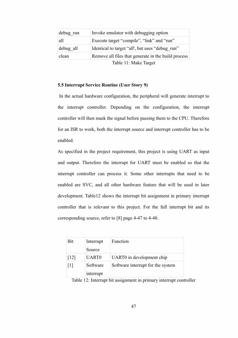
debug_run Invoke emulator with debugging option
all Execute target “compile”, “link” and “run”
debug_all Identical to target “all', but uses “debug_run”
clean Remove all files that generate in the build processTable 11: Make Target
5.5 Interrupt Service Routine (User Story 9)
In the actual hardware configuration, the peripheral will generate interrupt to
the interrupt controller. Depending on the configuration, the interrupt
controller will then mask the signal before passing them to the CPU. Therefore
for an ISR to work, both the interrupt source and interrupt controller has to be
enabled.
As specified in the project requirement, this project is using UART as input
and output. Therefore the interrupt for UART must be enabled so that the
interrupt controller can process it. Some other interrupts that need to be
enabled are SVC, and all other hardware feature that will be used in later
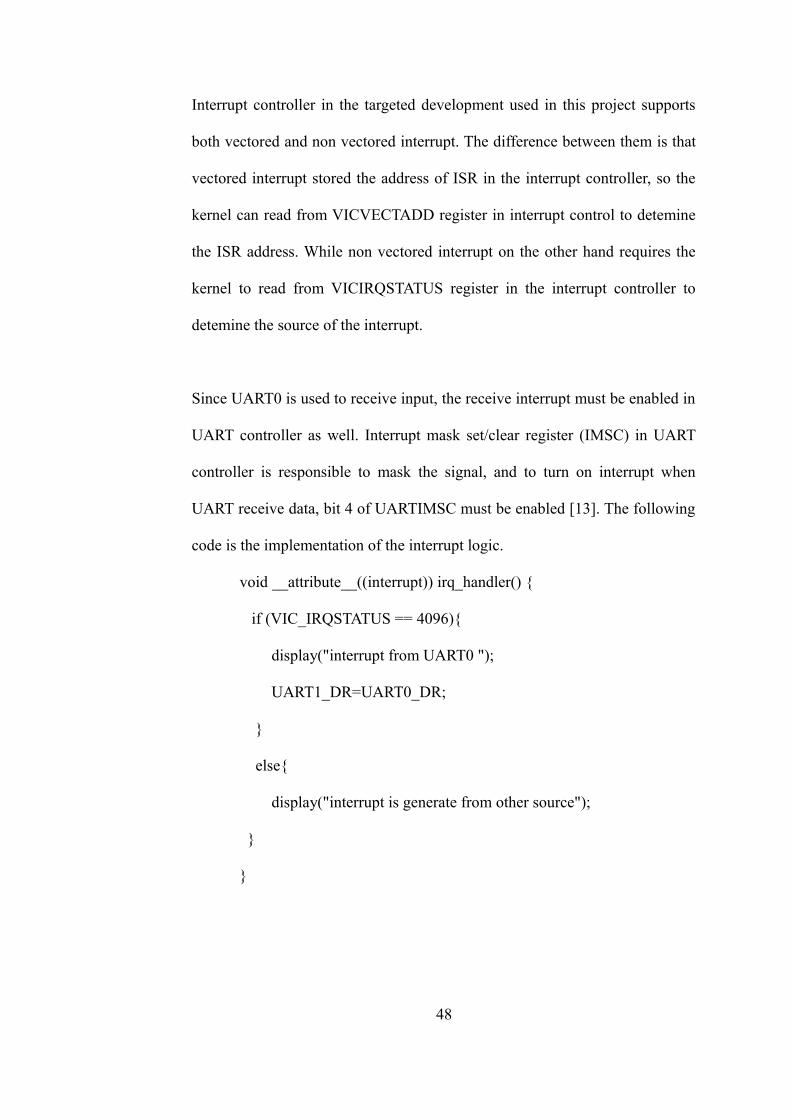
development. Table12 shows the interrupt bit assignment in primary interrupt
controller that is relevant to this project. For the full interrupt bit and its
corresponding source, refer to [8] page 4-47 to 4-48.
Bit Interrupt
Source
Function
[12] UART0 UART0 in development chip
[1] Software
interrupt
Software interrupt for the system
Table 12: Interrupt bit assignment in primary interrupt controller
47
Interrupt controller in the targeted development used in this project supports
both vectored and non vectored interrupt. The difference between them is that
vectored interrupt stored the address of ISR in the interrupt controller, so the
kernel can read from VICVECTADD register in interrupt control to detemine
the ISR address. While non vectored interrupt on the other hand requires the
kernel to read from VICIRQSTATUS register in the interrupt controller to
detemine the source of the interrupt.
Since UART0 is used to receive input, the receive interrupt must be enabled in
UART controller as well. Interrupt mask set/clear register (IMSC) in UART
controller is responsible to mask the signal, and to turn on interrupt when
UART receive data, bit 4 of UARTIMSC must be enabled [13]. The following
code is the implementation of the interrupt logic.
void __attribute__((interrupt)) irq_handler() {
if (VIC_IRQSTATUS == 4096){
display("interrupt from UART0 ");
UART1_DR=UART0_DR;
}
else{
display("interrupt is generate from other source");
}
}
48
5.6 System Operating Mode (User Story 10)
ARM processor stores its current operating mode into bit 0-4 in CPSR. When
writing these bits with new value, the processor mode is changed. The kernel
needs to keep track of the value in CPSR and restore them when the mode is
swithcing. However much of this work is handled by the compiler so unless
code is written in assembly, the developer is not required to write code to store
and restore CPSR value.
5.7 Memory Management Unit (User Story 11)
There are a few steps required to enable the MMU. First, the page descriptor
has to be created and copied into the memory. Then, C1, C2 and C3 in CP15
must be configured to enable the MMU.The page table will be stored in the
top 64 MB of SDRAM. Therefore the table will be copied into address from
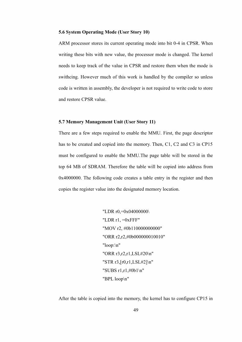
0x4000000. The following code creates a table entry in the register and then
copies the register value into the designated memory location.
"LDR r0,=0x04000000\
"LDR r1, =0xFFF"
"MOV r2, #0b110000000000"
"ORR r2,r2,#0b000000010010"
"loop:\n"
"ORR r3,r2,r1,LSL#20\n"
"STR r3,[r0,r1,LSL#2]\n"
"SUBS r1,r1,#0b1\n"
"BPL loop\n"
After the table is copied into the memory, the kernel has to configure CP15 in
49
order to turn on the MMU. The memory location of the translation tables are
set in translation table base register C2. The default value of all domain is 00
(no access), so the domains that will be used have to be configured. Two
domains are defined in this project, which are the manager in domain 0 and
client in domain 1. C1 in CP15 is the control register that the user can set to
configure the MMU. Bit 0 of C1 is the bit to enable/disable MMU. The
following code illustrates the steps described in this section.
LDR r0,=0x04000000
MCR p15,0,r0,c2,c0,0
MOV r0, #0xB
MCR p15, 0, r0, c3, c0, 0
MRC p15, 0, r0, c1, c0, 0
ORR r0, r0, #0x1
MCR p15, 0, r0, c1, c0, 0
5.8 Supervisor Call (User Story 12)
Part of the kernel function is to protect the kernel space and hardware from
direct access in user space program. In order for user space to access some of
the privilledge operation, kernel has to expose a list of system library that user
program can use. For example a printf c library is actually using few of the
system libraries to perform the printing function.
When a system call is made, the system will triggered a SVC interrupt, the
kernel will then branch into supervisor call routine and perform the necessary
operation. Unlike interrupt call where interrupt controller will put the source
into IRQSTATUS register, to identify which supervisor call is made, the kernel
has to read from the instruction itself. LR register stores the location where the
50
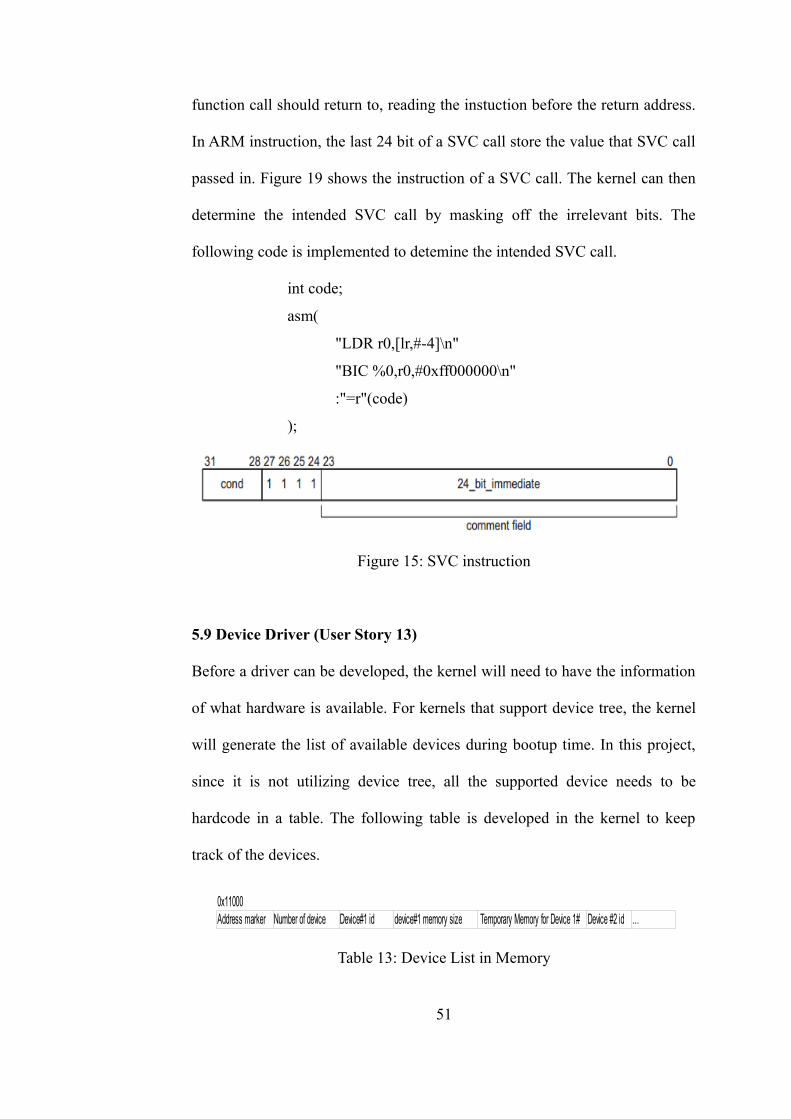
function call should return to, reading the instuction before the return address.
In ARM instruction, the last 24 bit of a SVC call store the value that SVC call
passed in. Figure 19 shows the instruction of a SVC call. The kernel can then
determine the intended SVC call by masking off the irrelevant bits. The
following code is implemented to detemine the intended SVC call.
int code;
asm(
"LDR r0,[lr,#-4]\n"
"BIC %0,r0,#0xff000000\n"
:"=r"(code)
);
Figure 15: SVC instruction
5.9 Device Driver (User Story 13)
Before a driver can be developed, the kernel will need to have the information
of what hardware is available. For kernels that support device tree, the kernel
will generate the list of available devices during bootup time. In this project,
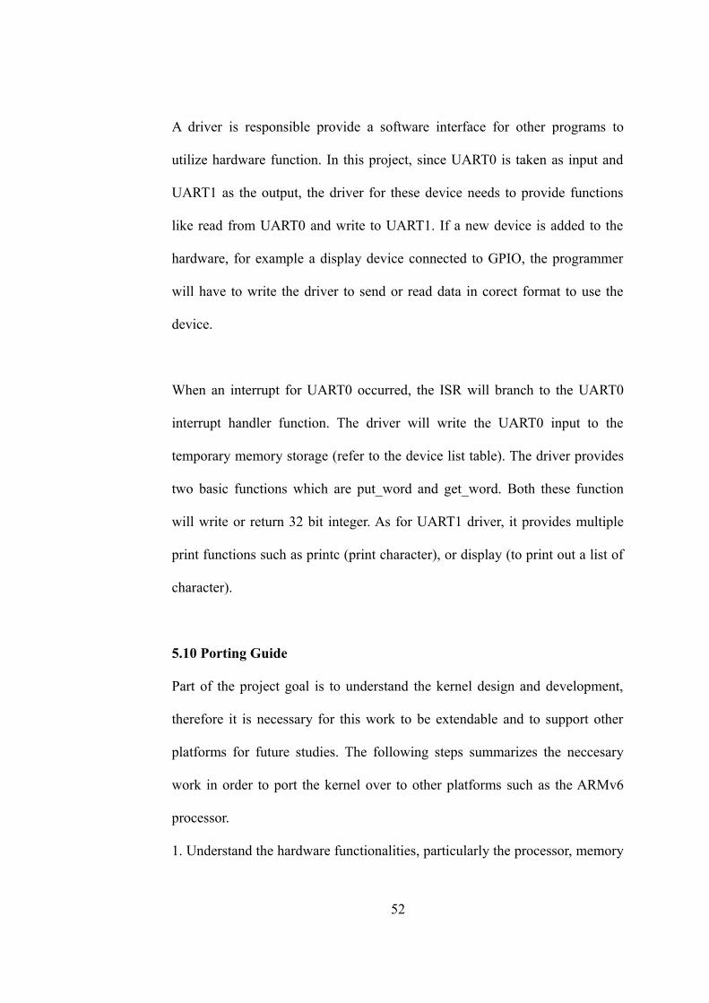
since it is not utilizing device tree, all the supported device needs to be
hardcode in a table. The following table is developed in the kernel to keep
track of the devices.
Table 13: Device List in Memory
51
0x11000Address marker Number of device Device#1 id device#1 memory size Temporary Memory for Device 1# Device #2 id …
A driver is responsible provide a software interface for other programs to
utilize hardware function. In this project, since UART0 is taken as input and
UART1 as the output, the driver for these device needs to provide functions
like read from UART0 and write to UART1. If a new device is added to the
hardware, for example a display device connected to GPIO, the programmer
will have to write the driver to send or read data in corect format to use the
device.
When an interrupt for UART0 occurred, the ISR will branch to the UART0
interrupt handler function. The driver will write the UART0 input to the
temporary memory storage (refer to the device list table). The driver provides
two basic functions which are put_word and get_word. Both these function
will write or return 32 bit integer. As for UART1 driver, it provides multiple
print functions such as printc (print character), or display (to print out a list of
character).
5.10 Porting Guide
Part of the project goal is to understand the kernel design and development,
therefore it is necessary for this work to be extendable and to support other
platforms for future studies. The following steps summarizes the neccesary
work in order to port the kernel over to other platforms such as the ARMv6
processor.
1. Understand the hardware functionalities, particularly the processor, memory
52
and interrupt feature.
2. Understand operating modes in the targeted platform
3. Comparison between the supported instruction set between the targeted
system and ARMv5
4. Setup a test environment with at least 1 input and 1 output
5. Pick the correct toolchain based on functionality, memory and performance
requirements
6. Replace incompatible assembly and C code
53
CHAPTER 6
6.0 Testing and Result
The traceability matrix is used in this project to keep track of use cases and
test cases.
6.1 Development environment test result
objdump is a binary utiliy in the toolchain that can display information about a
binary file. It provides various information of a binary file. Among the
available options, disassemble is an option that can help to debug a binary file
that was linked.
A simply C program to display the string “hello world!” is used to test the tool
chain. The program is compiled with debug information turned on.
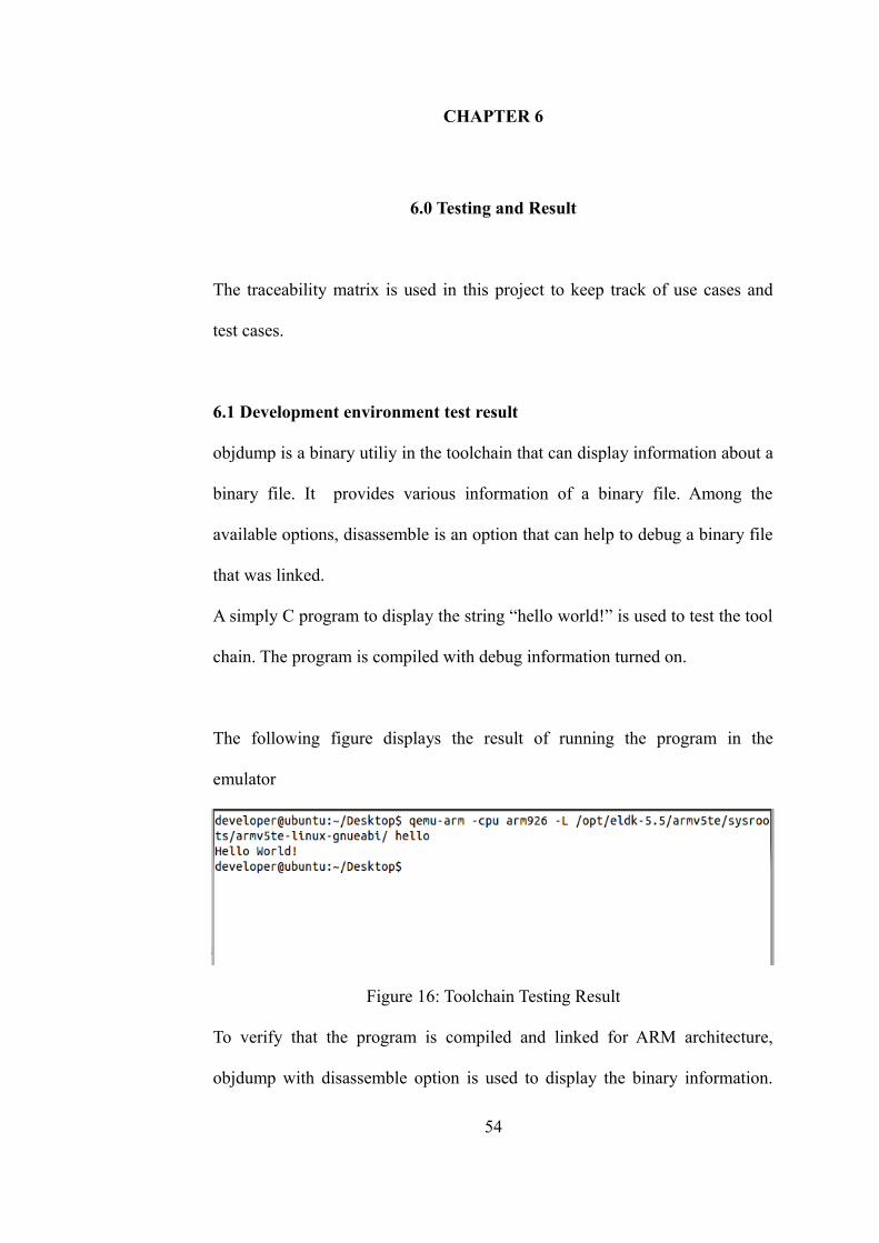
The following figure displays the result of running the program in the
emulator
Figure 16: Toolchain Testing Result
To verify that the program is compiled and linked for ARM architecture,
objdump with disassemble option is used to display the binary information.
54
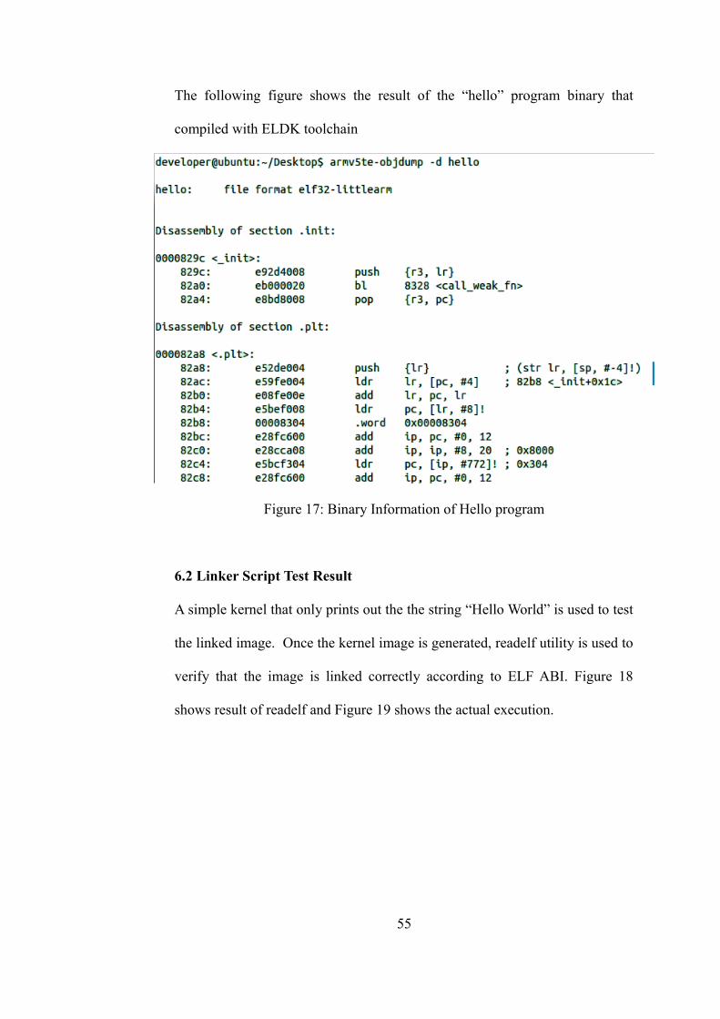
The following figure shows the result of the “hello” program binary that
compiled with ELDK toolchain
Figure 17: Binary Information of Hello program
6.2 Linker Script Test Result
A simple kernel that only prints out the the string “Hello World” is used to test
the linked image. Once the kernel image is generated, readelf utility is used to
verify that the image is linked correctly according to ELF ABI. Figure 18
shows result of readelf and Figure 19 shows the actual execution.
55
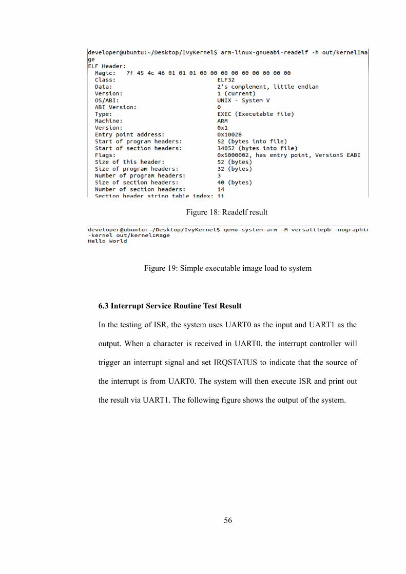
Figure 18: Readelf result
Figure 19: Simple executable image load to system
6.3 Interrupt Service Routine Test Result
In the testing of ISR, the system uses UART0 as the input and UART1 as the
output. When a character is received in UART0, the interrupt controller will
trigger an interrupt signal and set IRQSTATUS to indicate that the source of
the interrupt is from UART0. The system will then execute ISR and print out
the result via UART1. The following figure shows the output of the system.
56
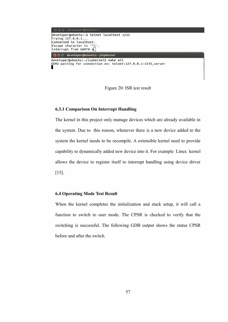
Figure 20: ISR test result
6.3.1 Comparison On Interrupt Handling
The kernel in this project only manage devices which are already available in
the system. Due to this reason, whenever there is a new device added to the
system the kernel needs to be recompile. A extensible kernel need to provide
capability to dynamically added new device into it. For example Linux kernel
allows the device to register itself to interrupt handling using device driver
[15].
6.4 Operating Mode Test Result
When the kernel completes the initialization and stack setup, it will call a
function to switch to user mode. The CPSR is checked to verify that the
switching is successful. The following GDB output shows the status CPSR
before and after the switch.
57
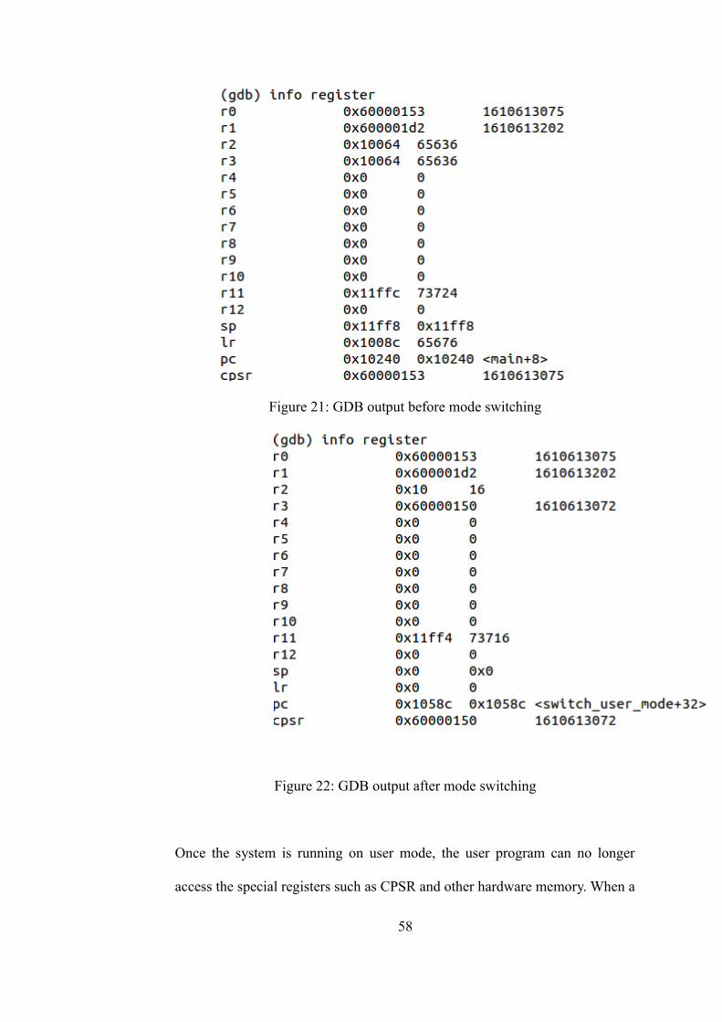
Figure 21: GDB output before mode switching
Figure 22: GDB output after mode switching
Once the system is running on user mode, the user program can no longer
access the special registers such as CPSR and other hardware memory. When a
58
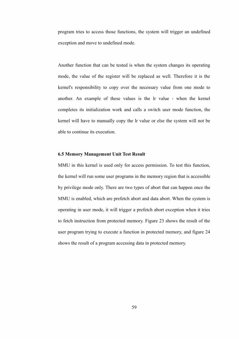
program tries to access those functions, the system will trigger an undefined
exception and move to undefined mode.
Another function that can be tested is when the system changes its operating
mode, the value of the register will be replaced as well. Therefore it is the
kernel's responsibility to copy over the necessary value from one mode to
another. An example of these values is the lr value - when the kernel
completes its initialization work and calls a switch user mode function, the
kernel will have to manually copy the lr value or else the system will not be
able to continue its execution.
6.5 Memory Management Unit Test Result
MMU in this kernel is used only for access permission. To test this function,
the kernel will run some user programs in the memory region that is accessible
by privilege mode only. There are two types of abort that can happen once the
MMU is enabled, which are prefetch abort and data abort. When the system is
operating in user mode, it will trigger a prefetch abort exception when it tries
to fetch instruction from protected memory. Figure 23 shows the result of the
user program trying to execute a function in protected memory, and figure 24
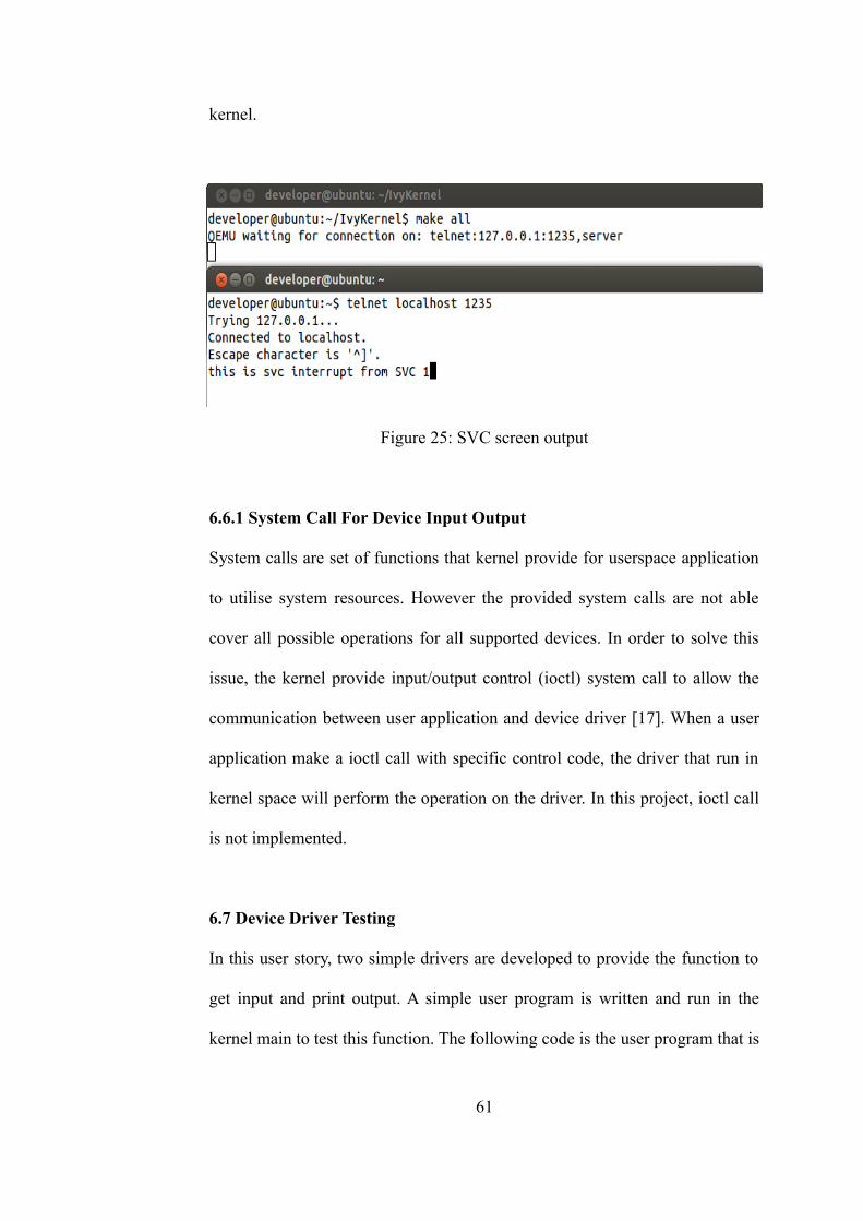
shows the result of a program accessing data in protected memory.
59
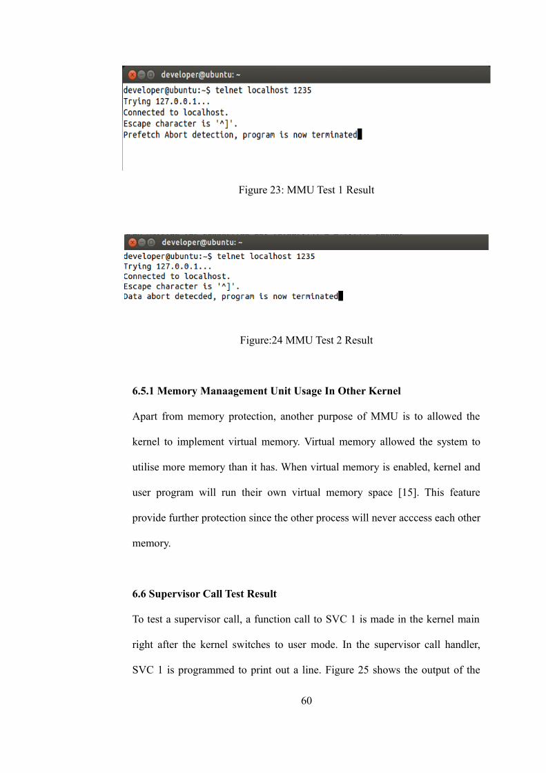
Figure 23: MMU Test 1 Result
Figure:24 MMU Test 2 Result
6.5.1 Memory Manaagement Unit Usage In Other Kernel
Apart from memory protection, another purpose of MMU is to allowed the
kernel to implement virtual memory. Virtual memory allowed the system to
utilise more memory than it has. When virtual memory is enabled, kernel and
user program will run their own virtual memory space [15]. This feature
provide further protection since the other process will never acccess each other
memory.
6.6 Supervisor Call Test Result
To test a supervisor call, a function call to SVC 1 is made in the kernel main
right after the kernel switches to user mode. In the supervisor call handler,
SVC 1 is programmed to print out a line. Figure 25 shows the output of the
60
kernel.
Figure 25: SVC screen output
6.6.1 System Call For Device Input Output
System calls are set of functions that kernel provide for userspace application
to utilise system resources. However the provided system calls are not able
cover all possible operations for all supported devices. In order to solve this
issue, the kernel provide input/output control (ioctl) system call to allow the
communication between user application and device driver [17]. When a user
application make a ioctl call with specific control code, the driver that run in
kernel space will perform the operation on the driver. In this project, ioctl call
is not implemented.
6.7 Device Driver Testing
In this user story, two simple drivers are developed to provide the function to
get input and print output. A simple user program is written and run in the
kernel main to test this function. The following code is the user program that is
61
used to test the driver function.
void user_program1() {
display("enter your character: ");
int user_input = 0;
while (user_input == 0)
user_input = get_word();
display("You entered: ");
printc(user_input);
}
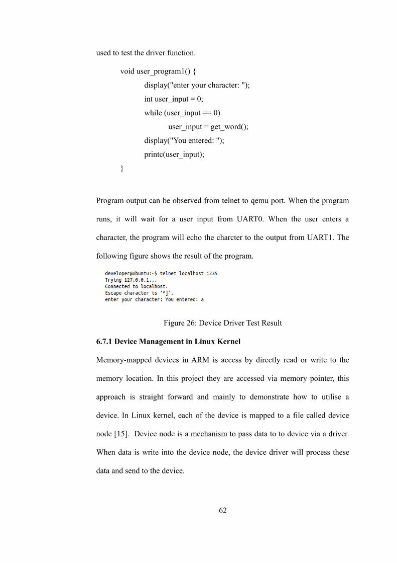
Program output can be observed from telnet to qemu port. When the program
runs, it will wait for a user input from UART0. When the user enters a
character, the program will echo the charcter to the output from UART1. The
following figure shows the result of the program.
Figure 26: Device Driver Test Result
6.7.1 Device Management in Linux Kernel
Memory-mapped devices in ARM is access by directly read or write to the
memory location. In this project they are accessed via memory pointer, this
approach is straight forward and mainly to demonstrate how to utilise a
device. In Linux kernel, each of the device is mapped to a file called device
node [15]. Device node is a mechanism to pass data to to device via a driver.
When data is write into the device node, the device driver will process these
data and send to the device.
62
6.8 Project Time line
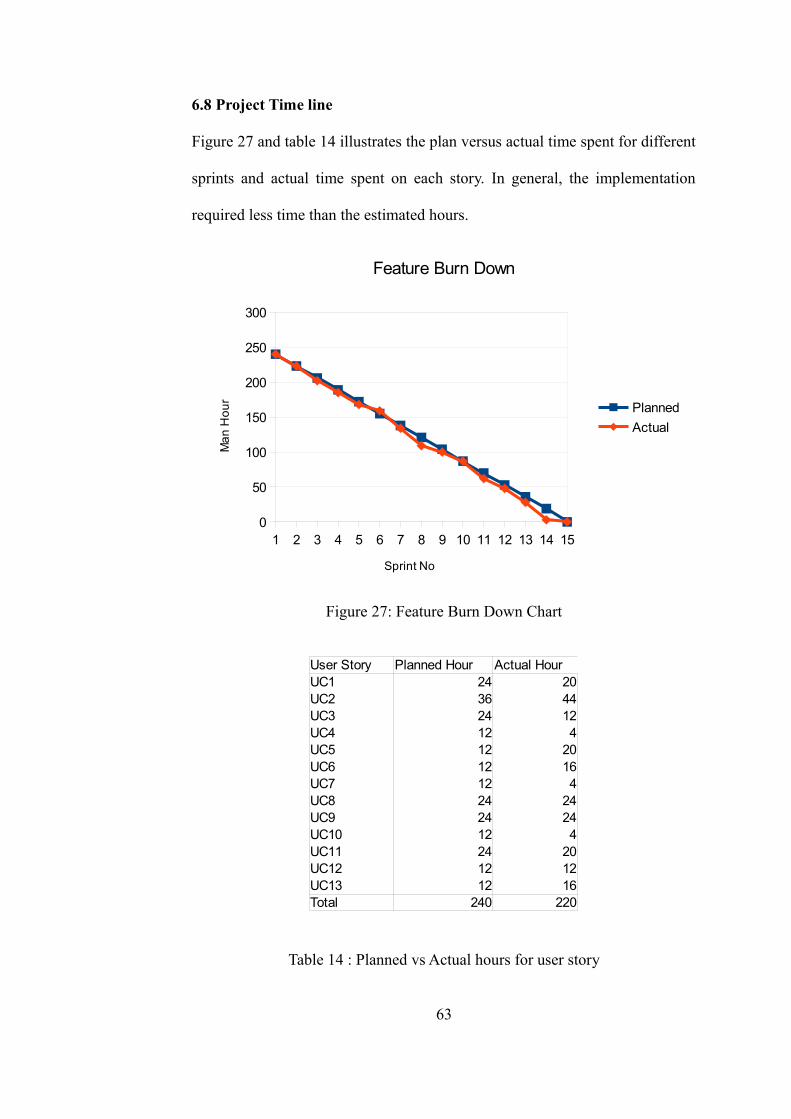
Figure 27 and table 14 illustrates the plan versus actual time spent for different
sprints and actual time spent on each story. In general, the implementation
required less time than the estimated hours.
Figure 27: Feature Burn Down Chart
Table 14 : Planned vs Actual hours for user story
63
1 2 3 4 5 6 7 8 9 10 11 12 13 14 150
50
100
150
200
250
300
Feature Burn Down
Planned
Actual
Sprint No
Ma
n H
ou
r
User Story Planned Hour Actual HourUC1 24 20UC2 36 44UC3 24 12UC4 12 4UC5 12 20UC6 12 16UC7 12 4UC8 24 24UC9 24 24UC10 12 4UC11 24 20UC12 12 12UC13 12 16Total 240 220
CHAPTER 7
7.0 CONCLUSION AND FUTURE WORK
The goal of this project is to understand and develop a kernel for RISC
architecture. In this project, the various aspect of kernel and kernel
development is discussed. Along with this documentation, a simple kernel was
developed to demonstrate the intergration between software and hardware.
Although this kernel lacks certain features, it is sufficiently simple to
understand and easy to experiment with.
Currently, the developed kernel lacks the complete virtual memory
implementation, process management and file system - these areas can be
futher developed as new projects. The kernel can also be futher developed into
a monolithic or micro kernel to further understand their differences.
64
Reference
[1] Zhou Qingguo, Ding Ying, McGuire, N., Li Canyu, Cheng Guanghui, and
Hu Bin, “A Case Study of Microkernel for Education”, IT in Medicine &
Education, 2009. ITIME '09. IEEE International Symposium Volume 1, pp.
133-136, 2000.
[2] Wang Chengjun, “The Analyses of Operating System Structure”,
Knowledge Acquisition and Modeling. Second International Symposium,
Volume 2, pp.354-357, 2009.
[3] Naufal Alee, Mostafijur Rahman, R. B. Ahmad, “Performance
Comparison of Single Board Computer : A Case Study of Kernel on ARM
Architecture”, Computer Science & Education (ICCSE), 2011 6th
International Conference, pp. 521-524, 2011.
[4] Messer, A., Wilkinson, T., “Components for Operating System Design”,
Object-Orientation in Operating Systems, 1996., Proceedings of the Fifth
International Workshop, pp. 128-132, 1996.
[5] Jorrit N. Herder, Herbert Bos, Ben Gras, Philip Homburg, Andrew S.
Tanenbaum, “MINIX 3: a highly reliable, self-repairing operating system”,
SIGOPS Oper. Syst. Rev., Vol. 40, No. 3. (2006), pp. 80-89.
[6] ARM instruction set architecture, ARM Limited, San Jose, C.A., 2005
[7] Migrating from IA32 to ARM, ARM Limited, San Jose, C.A., 2005
[8] Versatile Application Baseboard forARM926EJ-S User Guide, ARM
Limited, San Jose, C.A., 2005
65
[9] Tool Interface Standard (TLS) Executable and Linkable Format (ELF)
Specification v1.2, TIS Committee, 2005
[10 ] Application Binary Interface for the ARM architecture, ARM Limited,
San Jose, C.A., 2010
[11] Dandamudi, S.P, “Guide To Assembly Language Programming In Linux”,
Ottawa, Canada, 2005.
[12] ARM Procedure Call Standard, ARM Limited, San Jose, C.A., 2012
[13] Primcacell UART techinical reference manual, ARM Limited, San Jose,
C.A., 2005
[14] The Linux Information Project. “Kernel Definition,” www.linfo,org
[Online]. Available: http://http://www.linfo.org/kernel.html [Accessed: Apr.
30, 2014 ].
[15] C. Hallinan, Embedded Linix Primer. NJ, Prentice Hall, 2006.
[16] B.W. Kernighan and D. M. Ritchie, The C Programming Langugage,
Second Edition. NJ, Prentice Hall, 1988.
[17] Microsoft MSDN. “Device Input and Output Control (IOCTL),”
[Online]. Available: http://msdn.microsoft.com/en-
us/library/windows/desktop/aa363219(v=vs.85).aspx [Accessed : May 20,
2014].
66


![Linux Kernel Development: Getting Started Activities ...€¦ · Linux Kernel Development: ... Linux development is fast-paced and [as they say in Oregon] “things are different](https://img.dokumen.tips/doc/110x75/5ed12f2d50612c658265f08a/linux-kernel-development-getting-started-activities-linux-kernel-development.jpg)