Embed Size (px)
Citation preview
DEVELOPMENT OF GLOBAL VACUUM PRESSURE IMPREGNATION
INSULATION SYSTEM FOR TURBINE GENERATORS
Akinobu Nakayama, Kohji Haga, Seiichi InoueFuji Electric Corporate Research and Development, Ltd.
1-1 Tanabeshinden Kawasaki-ku, Kawasaki-city 210-8530, Japan
Key Words: VPI insulation system, stator winding,turbine generator, post impregnation insulation system
ABSTRACT Global vacuum pressure impregnation insulation systemexhibits various merits in insulation performance andreliability for operation including maintenance. Therefore,the system is suitable for ordinary turbine generators,especially, the generators for geothermal power plant. We have developed a global vacuum pressure impregnationinsulation system (F-resin/G insulation system) for largesize turbine generators and had put into practical use in1993. In the process of evaluation of insulation system, weevaluated impregnating ability, electrical, and mechanicalcharacteristics. From evaluation, we were able to achieve the improvementof heat cycle, heat resistance and V-t characteristics againstusual insulation system, because of the utilization of internalelectrical field relaxation layer, thermal stress relaxationlayer, insulation tapes with excellent impregnation abilityand epoxy resin with high heat resistance.As the insulation characteristics are affected not onlyutilized materials and their composition but alsomanufacturing process, it is reasonable to suppose that wecan obtain the improvement of insulation performances andstabilization of quality by using the taping simulationtechnique. 1. INTRODUCTION Fuji Electric has developed a global vacuum pressureimpregnation insulation system (F-resin/G insulationsystem) for large size turbine generators together withintroduction of required manufacturing equipment since1990, and had put into practical use in 1993. After that,numerous generators have been manufactured utilizing thisinsulation system and have been operated successfully. In the global vacuum impregnation insulation system, statorwinding inserted into stator is immersed in epoxy resin, andis impregnated under vacuum and pressure. Through thisVPI process not only the coil insulation is formed but alsothe resin penetrates into stator slot clearance, wedges andcoils. Additionally, all stator parts are coated by the resin.Furthermore, the stator coil insulation is impregnated by theresin continuously and rigidly from slot portion to coil endconductor connecting portion. Therefore, there are a lot of merits such as high reliability ofwinding, no looseness of stator core, corrosion proof,prevention of coil vibration as well as excellent heat
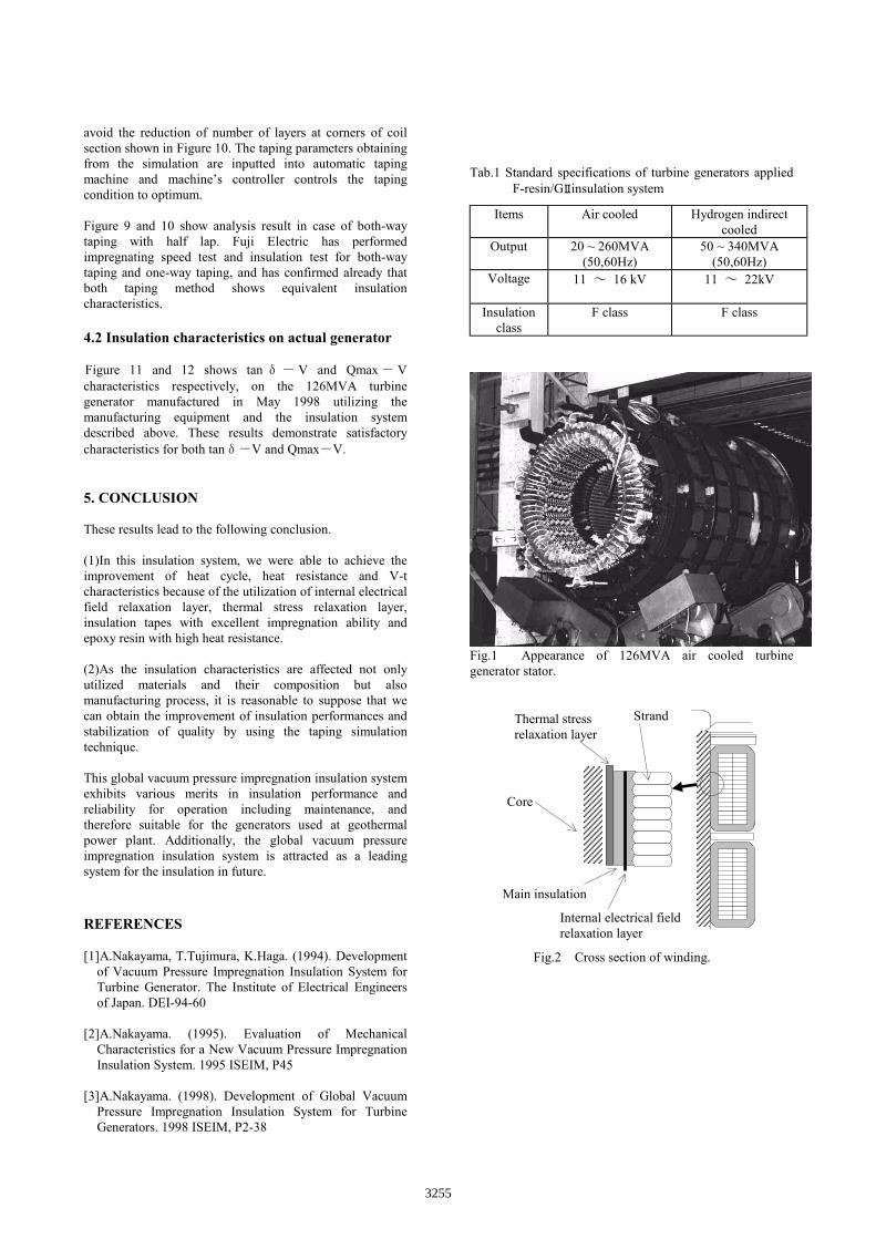
conductivity from the conductor to the core owing to fillingup of stator slot clearance by the resin. Furthermore,replacement of wedges are not required because no wedgelooseness is induced. These features are suitable for ordinaryturbine generators, especially, the generators for geothermalpower plant, surrounded by atmosphere containinghydrogen sulfide Though this insulation system is mainly applied to aircooled turbine generators with output range of from 20 to260MVA, it is also possible to manufacture hydrogencooled turbine generators with output range of from 50 to340MVA, utilizing the merits of global vacuum pressureimpregnation insulation system. Table 1 shows standardspecifications of turbine generators applied the F-resin/GⅡinsulation system and Figure 1 shows appearance of126MVA air cooled turbine generator stator.
2. FEATURES OF F-RESIN/G INSULATUIONSYSTEM
Global vacuum pressure impregnation insulation systemretains many merits such as improvement of insulationperformances, stabilization of quality, shortening ofmanufacturing period and mitigation of maintenance load.In particular, since an thermal stress relaxation layer isprovided in the F-resin/G insulation system, a stable heat-cycle resistance characteristic is realized and enables toserve for the DSS (daily start and stop) operation modewhich corresponds to current power demand.
The main features of the F-resin/G insulation system arelisted below, and Figure 2 shows cross section of winding.
・ Utilization of epoxy impregnation resin with longenduring life and high heat resistance.
・ Utilization of main insulation tapes with excellentimpregnation ability.
・Utilization of internal electrical field relaxation layer・Utilization of thermal stress relaxation layer
Ⅱ
Ⅱ
Ⅱ
Ⅱ
Ⅱ
3253
3. EVALUATION TEST RESULTS ON MODELCOILS
3.1 Impregnating ability characteristics
The most important factor in the global vacuum pressureimpregnation insulation technique is that the resin should bepenetrated sufficiently into the insulation layers at the timeof impregnation.
In order to achieve this requirement, a test for impregnatingvelocity by measuring electrostatic capacity is performed toselect the main insulation tapes. The main insulation tape iscomprised of mica paper, glass cloth, binder and accelerator.The factors to affect the impregnation are kind and quantityof the accelerator, kind and quantity of the binder, tension oftaping work, air permeability of the tape and viscosity of theresin.
Fuji Electric has selected several main insulation tapesappropriate to this insulation system through the varioustests for impregnating ability. The impregnating abilitycharacteristic of these tapes is shown in Fig. 3. Thecharacteristics shown in Fig. 3 are that of model coils, andthe impregnation process completed within about 140minutes, and it is obvious that all tapes have thecharacteristics appropriate for the high voltage insulation.
3.2 Heat cycle characteristics Figure 4 and 5 shows tanδ-V characteristics and partialdischarge characteristics respectively during heat cycle testup to 400 cycles. The test coils on 16.5kV class arecomposed of guard electrodes and are provided with both aninternal electrical field relaxation layer as well as a thermalstress relaxation layer.
As shown in Figure 4, the tanδ-V characteristic after 400heat cycles is getting worse a little, affected by cracks andvoids inside the insulation layers due to the heat cycles,however, it still preserves enough margin for an allowablelimit.
Furthermore, it is known in Figure 5, that the partialdischarge increases a certain degree in relation to heat cycles,however, it is deemed as stable since an increasing rate ofpartial discharge is rather small.
In generally, cracks and microscopic voids will be generatedin the insulation wall by repeated expansion and contractionconsequent upon the heat cycles, therefore the insulationcharacteristics after heat cycles become worse. However,thermal stress relaxation layer provides an ability to obstructthe invasion of cracks resulted from heat cycle into maininsulation wall, while internal electrical field relaxationlayer relaxes electric field strength nearby conductors. It issupposed that heat cycle characteristics was improved bythese effects.
3.3 Heat resistance characteristics
Through the utilization of a resin hardener with high heatresistance for this insulation system, the heat resistancecharacteristics of insulation wall have been remarkablyimproved.
Figure 6 shows dielectric strength of test coils on 16.5kVclass that have heated to 160oC and 180oC during 3000 hours.It is clearly understood that the test coils have superiordielectric strength at initial condition, and it is kept almost atthe same level even after the heating of 3000 hours.
3.4 V----t characteristics
The dielectric strength is decreased by voltage applicationduring long term. Figure 7 shows V-t characteristics of testcoils on 16.5kV class with/without the internal electricalfield relaxation and thermal stress relaxation layer. Thoughthe dielectric strength at earlier phase are almost identicalregardless of existence of relaxation layers, the test coils ofrelaxation layers model demonstrate longer life with the timethan others against the identical electric field.
3.5 Mechanical Characteristics
Figure 8 shows repeated bending fatigue test results for boththe F-resin/GⅡinsulation system (mica paper+glass tape)and the conventional insulation system (flake mica+fleecebased tape).
The F-resin/G insulation system demonstrates highertoughness compared with the conventional one.The big fatigue characteristic differences between bothinsulation systems are resulted from difference of usedmaterials. One of major factors is composition of mica. Incase of flake mica, since wide cracks are formed byexfoliation of mica flake due to bending stress, break downvoltage may be decreased. On the contrary, in case of micapaper, since impregnation resin is penetrated without voidsdue to fine mica particles, exfoliation of mica particles dueto bending stress may be small. Furthermore, glass base(glass cloth) is utilized for F-resin/G insulation, whilefleece base (unwoven polyester fabric) is utilized forconventional insulation. Improvement of fatigue strengthmay be attributable to higher mechanical strength ofinsulation with glass base.
4. MANUFACTURING METHOD ANDINSULATION CHARACTERISTICS FORACTUAL GENERATOR
4.1 Simulation technology of taping
Insulation characteristics of stator coils are affected not onlythe applied materials but also the manufacturing method.For an example, taping method of main insulation tapescauses a change of BVD characteristics. Therefore, it isessential to secure the stable insulation characteristics withthe help of the optimum taping conditions.
Figure 9 and 10 shows an analyzed example by computerprogram originally developed by Fuji Electric, whichenables verification of taping conditions. Figure 9 showslayer state of insulation wall over longitudinal cross sectionof a coil. Figure 10 shows isolayers distribution over coilinsulation surface.
The essential point to manufacture high reliable coils is to
Ⅱ
Ⅱ
3254
avoid the reduction of number of layers at corners of coilsection shown in Figure 10. The taping parameters obtainingfrom the simulation are inputted into automatic tapingmachine and machine’s controller controls the tapingcondition to optimum.
Figure 9 and 10 show analysis result in case of both-waytaping with half lap. Fuji Electric has performedimpregnating speed test and insulation test for both-waytaping and one-way taping, and has confirmed already thatboth taping method shows equivalent insulationcharacteristics.
4.2 Insulation characteristics on actual generator
Figure 11 and 12 shows tan δ- V and Qmax - Vcharacteristics respectively, on the 126MVA turbinegenerator manufactured in May 1998 utilizing themanufacturing equipment and the insulation systemdescribed above. These results demonstrate satisfactorycharacteristics for both tanδ-V and Qmax-V.
5. CONCLUSION
These results lead to the following conclusion.
(1)In this insulation system, we were able to achieve theimprovement of heat cycle, heat resistance and V-tcharacteristics because of the utilization of internal electricalfield relaxation layer, thermal stress relaxation layer,insulation tapes with excellent impregnation ability andepoxy resin with high heat resistance.
(2)As the insulation characteristics are affected not onlyutilized materials and their composition but alsomanufacturing process, it is reasonable to suppose that wecan obtain the improvement of insulation performances andstabilization of quality by using the taping simulationtechnique.
This global vacuum pressure impregnation insulation systemexhibits various merits in insulation performance andreliability for operation including maintenance, andtherefore suitable for the generators used at geothermalpower plant. Additionally, the global vacuum pressureimpregnation insulation system is attracted as a leadingsystem for the insulation in future.
REFERENCES
[1]A.Nakayama, T.Tujimura, K.Haga. (1994). Developmentof Vacuum Pressure Impregnation Insulation System forTurbine Generator. The Institute of Electrical Engineersof Japan. DEI-94-60
[2]A.Nakayama. (1995). Evaluation of MechanicalCharacteristics for a New Vacuum Pressure ImpregnationInsulation System. 1995 ISEIM, P45
[3]A.Nakayama. (1998). Development of Global VacuumPressure Impregnation Insulation System for TurbineGenerators. 1998 ISEIM, P2-38
Tab.1 Standard specifications of turbine generators appliedF-resin/G insulation system
Items Air cooled Hydrogen indirectcooled
Output 20 ~ 260MVA(50,60Hz)
50 ~ 340MVA(50,60Hz)
Voltage 11 ~ 16 kV 11 ~ 22kV
Insulationclass
F class F class
Fig.1 Appearance of 126MVA air cooled turbinegenerator stator.
Internal electrical fieldrelaxation layer
Thermal stressrelaxation layer
Strand
Core
Main insulation
Fig.2 Cross section of winding.
Ⅱ
3255
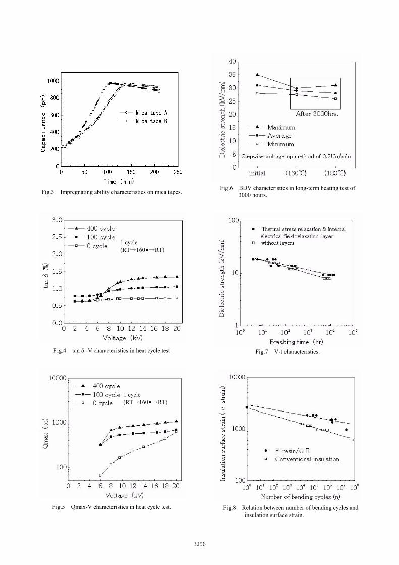
Fig.3 Impregnating ability characteristics on mica tapes.
Fig.4 tanδ-V characteristics in heat cycle test
.
Fig.5 Qmax-V characteristics in heat cycle test.
Fig.6 BDV characteristics in long-term heating test of 3000 hours.
Fig.7 V-t characteristics.
Fig.8 Relation between number of bending cycles and insulation surface strain.
1 cycle(RT→160•→RT)
1 cycle(RT→160•→RT)
3256
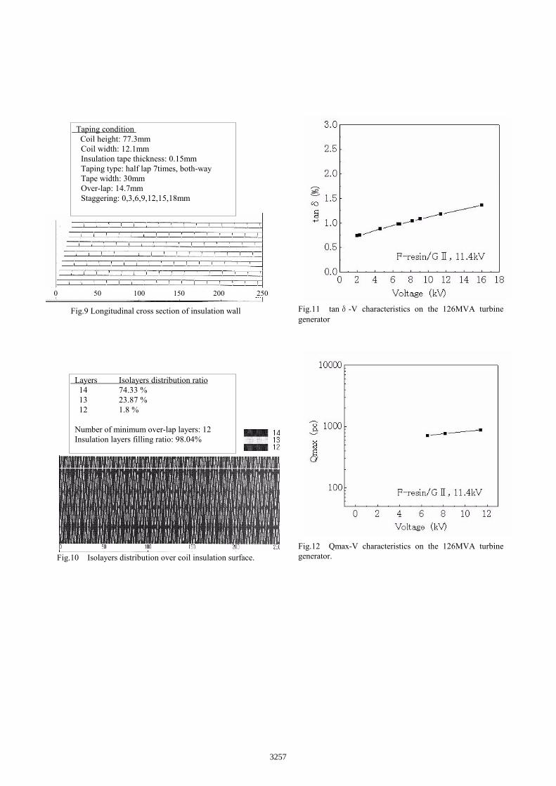
Fig.9 Longitudinal cross section of insulation wall
Fig.10 Isolayers distribution over coil insulation surface.
Fig.11 tanδ-V characteristics on the 126MVA turbinegenerator
Fig.12 Qmax-V characteristics on the 126MVA turbinegenerator.
0 50 100 150 200 250
Taping condition Coil height: 77.3mm
Coil width: 12.1mmInsulation tape thickness: 0.15mmTaping type: half lap 7times, both-wayTape width: 30mmOver-lap: 14.7mmStaggering: 0,3,6,9,12,15,18mm
Layers Isolayers distribution ratio 14 74.33 % 13 23.87 % 12 1.8 %
Number of minimum over-lap layers: 12 Insulation layers filling ratio: 98.04%
3257