Embed Size (px)
Citation preview
DEVELOPMENT OF CONCRETE LINK SLABS TO ELIMINATE BRIDGE EXPANSION JOINTS OVER PIERS
Clifford Lam, Head, Bridge Research, Ministry of Transportation of Ontario David Lai, Head, Bridge Rehabilitation, Ministry of Transportation of Ontario Jim Au, Senior Design Engineer, Ministry of Transportation of Ontario Leong Lim, Structural Engineer, SWR, Ministry of Transportation Ontario Wade Young, Head, Structural Section, SWR, Ministry of Transportation of Ontario Bala Tharmabala, Manager, Bridge Office, Ministry of Transportation of Ontario
Paper prepared for presentation at the Bridges - Links to a Sustainable Future (B) Session of the 2008 Annual Conference of the Transportation Association of Canada Toronto, Ontario
- 1 -
ABSTRACT
One of the primary factors affecting the durability of bridge structures is the use of expansion joints at bridge support locations. The inability of current joint systems to provide reliable and effective long-term leakproof performance generally leads to early leakage of chloride-contaminated water through those joints, thereby causing premature corrosion at girder ends and supporting substructures below. This problem is particularly evident in older-type multi-span bridges in which the girders are simply supported at the piers and are separated by expansion joints or paved-over joints. To address this problem, the Ministry of Transportation of Ontario has tried to eliminate the expansion joints during deck rehabilitation by using a number of approaches. This paper describes some of the systems that have been implemented in recent projects: (i) converting the simply-supported spans into a semi-continuous deck system by encasing the girder ends in a monolithic transverse concrete diaphragm, (ii) linking the simple spans by a thin concrete slab (flexible link slab) that spans between haunched beam sections on either side of link slab while keeping the girders discontinuous; and (iii) using a similar link slab concept except that the link slab is debonded from the girders for a longer length at each girder end. The paper discusses the relative merits of these systems from both technical and economic standpoints and provides examples of recent field applications of each system. The practical lessons that were learned and the field performance of each system to date are also presented. Key Words: Bridge expansion joints, durability, water leakage, deck rehabilitation, flexible link slab, debonded link slab
- 2 -
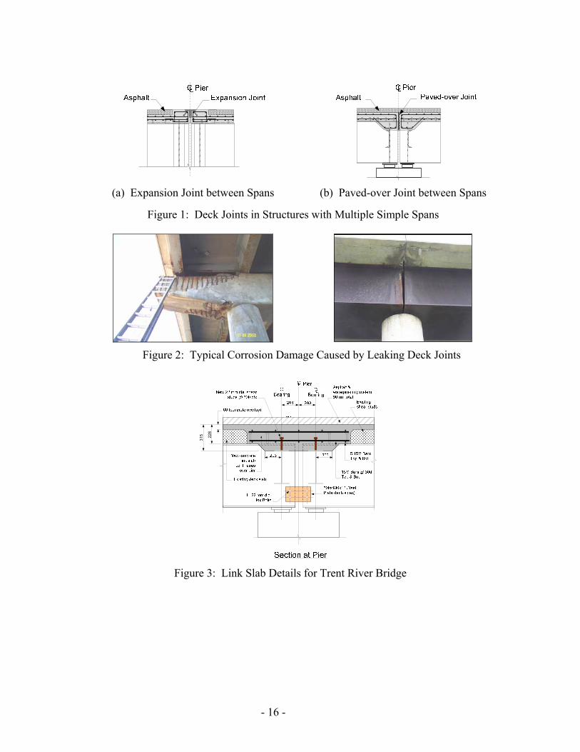
INTRODUCTION It was common practice before the 1970’s to design multiple-span bridges as single-span structures, which were simply-supported on piers and then connected by expansion joints or paved-over joints at the pier locations (Figure 1). While this system provided a simple and effective structural solution, it brought along a range of maintenance issues that have compromised the durability of many of these structures. Historically, bridge expansion joints have never performed up to design expectations. Their recurring inability to provide reliable and effective long-term leakproof performance has led to early leakage of chloride-contaminated water through those joints, thereby causing premature corrosion at girder ends and supporting substructures below. Typically, the damage is exemplified by cracking, spalling and disintegration of the concrete deck slab in the area adjacent to the joints as well as spalling and delamination of the concrete around the bearing seat and pier cap below (Figure 2). To address this problem, the Ministry of Transportation of Ontario (MTO) has tried to eliminate the expansion joints in older bridges by using a number of approaches that included converting the simply-supported spans into a semi-continuous deck system by encasing the girder ends in a monolithic transverse concrete diaphragm or providing continuity of the concrete deck slab over the piers by means of a link slab segment while keeping the supporting girders discontinuous. This paper discusses some recent deck rehabilitation projects, structural solutions that were adopted, their performance and subsequent improvements that were made based on field experience and finally a comparison of the costs of the different systems.
PROVIDING DECK CONTINUITY OVER PIERS Haunched Deck Slab System One of the first ministry bridges that was rehabilitated with a link slab detail as a means of eliminating existing deck joints over piers is the Trent Canal Bridge, which carries Hwy 12 over the Trent Canal north of Beaverton. The bridge was originally designed with four single spans, which were simply supported on concrete piers. Deck movements were accommodated by expansion joints at all pier locations, with a 25 mm gap between spans. The original deck superstructure consisted of a 178 mm thick concrete slab that was made composite with six supporting steel girders spaced about 2.0 m apart. Rehabilitation Details: The deck was rehabilitated in 1995, when the expansion joints at the piers were eliminated and the deck slab was made continuous at those locations, while the girders remained discontinuous. A 1.2 m wide section of the deck at the pier locations was replaced with a link slab with an overall haunch depth of 315 mm and topped with a 60 mm thick concrete overlay (Figure 3). The link slab was reinforced longitudinally with top and bottom layers of 15M steel bars at 300 mm spacing and transversely by two layers of five 15M steel bars at both top and bottom of the slab. The haunched section of the link slab was made composite with the existing transverse diaphragm members by a single row of 22 mm diameter shear connectors spaced at 300 mm on each diaphragm. The webs of the existing girders were
- 3 -
connected by two 12 mm thick splice plates that were bolted to the girder web with four 22 mm diameter hex bolts. Field Observations: The rehabilitated bridge has been in service for over thirteen years and based on the biennial visual inspections of the bridge, the link slab detail has performed well. There has not been any evidence of cracking or water leakage at the soffit of the link slab and the condition of the asphalt over the link slab has been generally good. This system was implemented as a trial project and has not been used as a routine method for eliminating deck joints. Flexible Link Slab System In 1987, the City of Toronto started to use a “flexible link” design [1] to eliminate deck joints in bridges on the Gardiner Expressway. The “flexible link” is a continuous thin concrete slab (150 to 180 mm thick) that spans between haunched beam sections (315 to 375 mm deep) cast on top of the transverse diaphragms at the ends of adjoining girders while the girders are kept discontinuous. Following good performance reviews of this link slab detail during the initial years of service, the ministry decided to adopt a similar design in some deck replacement projects in 1996. The first ministry bridge in which the flexible link slab system was implemented is the Kent County Road No. 10/Hwy 401 Underpass. This bridge carries the regional road Kent County Road No.10 over Highway 401 outside of Chatham in Southwest region. It was rehabilitated in 1996 and in addition to the first implementation of the flexible link slab detail in a provincial bridge, it also featured the first application of the “steel-free deck” system, an innovative concept that was also developed by MTO. Kent County Road No. 10/ Hwy 401 Underpass: This bridge was initially designed as a simply-supported structure with four single spans that were supported on three pier bents. The original deck system consisted of a 178 mm thick concrete slab that was made composite with six longitudinal steel I-girders spaced 2.134 m apart. The deck joints at the pier bents were typically caulked and paved over with a continuous asphalt paving. Rehabilitation Details: The deck was replaced by a new 225 mm thick concrete deck, which was made composite with the existing steel girders. The gap between the simply-supported spans was bridged by a flexible link slab detail, similar to the design used by City of Toronto [1], while the girders remained discontinuous. The link slab was 150 mm thick and 460 mm wide and spanned between two haunched beams, 380 mm deep by 660 mm wide, which were designed to provide the rigidity such that any rotation and cracking were confined to the link slab element. The relatively thin and short link slab provided the continuity over the pier supports and was designed to accommodate the end-rotations of the simply-supported girders. The overall width of slab that needed to be cut out and replaced by the new link slab was about 1.78 m.
- 4 -

A portion of the top flange of adjoining steel girders was coped to provide rotational freedom at the girder ends. A 20 mm thick steel continuity plate was welded to the top of adjacent girders primarily to maintain a uniform gap between the top flanges during construction and also to minimise the possibility of cracks forming in the link slab concrete during the initial curing due to traffic on the adjoining lane. To further protect the link slab from possible salt ingress, rubber membrane reinforcement was laid over the link slab to reinforce the waterproofing system. The link slab was reinforced longitudinally with 15M bars @ 75 mm spacing (top and bottom) and transversely with 15M bars @ 150 mm (top and bottom). In addition, shear reinforcement was provided in the link slab and consisted of 6 mm diameter stainless steel ties spaced 75 mm apart. These reinforcing details were designed for a maximum rotation of 0.17 deg (0.003 rad) at the girder ends and to satisfy the OHBDC [2] serviceability requirement of a maximum crack width of 0.25 mm. Due to the continuity of the deck slab over the entire bridge length of 66.4 m, new elastomeric bearing pads were installed at both abutments to accommodate the full design thermal movement while the existing interior support bearings allowed full translation capability for the bottom flanges. To allow full unrestricted rotation of the link slab due to live load on the structure, it was decided to install a bond breaker underneath the barrier wall over the full length of the link slab. In addition, full discontinuity of the barrier wall was ensured at the pier centreline by installing a 13mm rigid bond breaker over the full depth of the barrier (Figure 5). Construction Notes: One of the main observations that were made during construction of the link slab was the heavy congested nature of the reinforcement details, which made rebar placement and concreting an onerous task. It was felt that the design and detailing needed to be reviewed to achieve better constructability of this type of deck rehabilitation. Field Observations: Visual inspections of this structure in 1997 and 1998 revealed that the link slab was performing well structurally. There was no evidence of cracking or water leakage at the soffit of the link slab itself and the condition of the asphalt over the link slab was good. However, there were signs of water leakage at the fascia of the deck in the area just below the bond breaker that was placed underneath the barrier wall. This detail would need to be improved to prevent water from seeping through the bottom of the barrier wall. MTO’s Flexible Link Slab Design Guidelines Based on the experience obtained from the deck rehabilitation of the Kent County Road No. 10/ Hwy 401 Underpass and to facilitate the use of the flexible link slab system in future ministry projects, MTO conducted an in-depth assessment of the flexible link slab design. This led to the development of new design guidelines and standards for its application and the release of a ministry report entitled “Development of Flexible Link Slab for Elimination of Existing Expansion Joints on Steel Girder Bridges” in 2001 [3]. The main highlights of the guidelines are:
- 5 -
• Provision of standard link slab details:
− Link slab dimensions to be 180 mm thick and 460 mm wide with an overall deck replacement width of 2.0 m.
− Haunched beam section to be 350 mm thick on either side of link slab to confine cracking within link slab.
• Provision of standard reinforcement details:
− Longitudinal 15M bars @ 100 mm top & bottom if unfactored rotation due to live load is less 0.0032 radian or unfactored rotation due to superimposed dead load and live load is less than 0.0040 radian.
− Longitudinal 20M bars @ 125 mm top & bottom if unfactored rotation due to live load is less 0.0037 radian or unfactored rotation due to superimposed dead load and live load is less than 0.0046 radian.
− Transverse 15M bars @ 200 top & bottom − 4 – 15M stainless steel bars @ 100 top & bottom in link slab under barrier wall.
• Provision of following barrier details at pier centreline:
− Upper part of barrier wall to be fully discontinuous including rebars to provide flexibility for the link slab to rotate.
− Lower 250 mm thick section of barrier to be fully continuous including rebars to prevent water leakage at base of barrier wall.
• Limitations on the use of the link slab system:
− Unfactored rotation at girder ends due to live load to be less than 0.0035 radian. − Unfactored rotation at girder ends due to superimposed dead load and live load to be less
than 0.0046 radian. − Bridge skew to be less than 20o. − Girder depth to be less than 1.2 m.
• Recommendations for bridges exceeding above limitations:
− Full continuity to be provided for girders over piers by encasing girder ends in concrete diaphragm.
− Deck replacement width to be at least 4.5 m wide. − New deck slab to be reinforced longitudinally with 15M bars @ 150 mm for top layer.
Applications of Flexible Link Slab System per MTO Guidelines The recommendations from the MTO design guidelines were first implemented in the deck slab rehabilitation of Hwy 427 SBL Overpass @ Dixon Road in Central Region in 1997. Details of the project are described in the following. Note that a total of about six additional structures have since been rehabilitated using this system in Ontario. Hwy 427 SBL Overpass @ Dixon Road: This bridge was designed initially as a simply-supported structure with four single spans that were supported on three pier bents. The original
- 6 -
deck system consisted of a 180 mm thick concrete slab that was made composite with twelve longitudinal steel I-girders spaced approximately 2.1 m apart. Rehabilitation Details: The existing deck was rehabilitated in 1997 as follows: (a) the deck was widened by approximately 6.0 m with the addition of a new 225 mm thick slab, and (b) the existing deck joints at the pier supports were replaced with a continuous 2.0 m wide link slab element that bridged the gap between adjacent girders, which remained discontinuous at the piers. The link slab system (Figure 6) was generally similar to the design used in the first trial application at the Kent County Road No. 10/Hwy 401 Underpass. The main differences were due to the implementation of the recommendations of the new design guidelines, which included revised reinforcement in the link slab and new barrier wall details over the link slab (Figure 7). Note that the shear ties were still used in this structure but they were dropped in later projects. Field Observations: Visual inspections of this structure in 1998 revealed that the link slab was performing well structurally. There was no evidence of cracking or water leakage at the soffit of the link slab itself and the condition of the asphalt over the link slab was good. In addition, there were no signs of water leakage at the fascia of the deck in the area above the bridge pier supports. This confirmed that the revised barrier wall detail used in this bridge (Figure 7) had resolved the water leakage problem that was observed at the Kent County Road No. 10/Hwy 401 Underpass. However, a subsequent inspection in 2000 revealed the presence of medium to wide cracks under the fascia and based on the efflorescence that was observed around the cracks, water leakage was still occurring. Limitations of Flexible Link Slab System As discussed earlier, limitations were placed on the use of the flexible link slab system under certain geometrical and flexural conditions of the structure. These restrictions were introduced primarily to ensure that serviceability limit state design conditions were met when using the standard details proposed in the guidelines. The limitations were related to (a) end rotations of the girders under live load, (b) bridge skew and (c) girder depth. For those cases where the standard flexible link detail cannot be used, a different rehabilitative procedure will be needed and two alternative systems can be used instead: (1) Convert the simply-supported spans into a semi-continuous deck system for live load by
encasing the girder ends in a monolithic transverse concrete diaphragm that is fully connected to the girders by shear studs in order to transfer the negative moments caused by live load and other superimposed dead loads.
(2) Use a similar link slab concept as described above except that the concrete link slab is
debonded from the girders for a longer length at each girder end. This provides the link slab with the flexibility required to accommodate the end-rotations of the girders thereby eliminating the need for the haunched beam sections designed to confine any cracking to the link slab. To differentiate from the flexible link slab system discussed above, this new system will be referred to as the debonded link slab system.
- 7 -
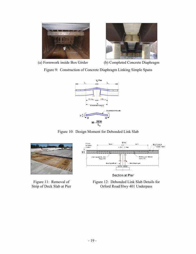
The ministry has used both approaches in recent deck rehabilitation projects in which existing deck joints were eliminated. Details of some typical recent projects are described in the following to illustrate the structural concept of these alternative solutions. Semi-Continuous Deck System This system is recommended for bridges with a skew of more than 200 or with longitudinal girders that exceed 1.2 m in depth [3]. It was implemented in the deck rehabilitation of a two-span steel box girder bridge in Southwest region in 2004 as described in the following. Uttoxeter Road/Hwy 402 Underpass: This bridge was designed initially as a two simple-spans structure, spanning over Highway 402, about 25 km east of Sarnia. The deck superstructure consisted of two steel box girders, approximately 1.325 m deep, with a 180 mm thick composite concrete deck slab cast on top. It has two equal and simply-supported spans of 38.4 m length each in its original configuration and was supported on conventional abutments at the ends and a pier bent system at the centre. Rehabilitation Details: The bridge was rehabilitated in 2004, in which all the expansion joints were eliminated as follows: (a) semi-integral abutment connections were provided at both ends of the structure and (b) the structure was made semi-continuous for live load. The box girder had a depth of approximately 1.30 m, which exceeded the 1.2 m depth limitation of the flexible link slab design. Instead, the simply-supported spans were converted into a semi-continuous deck system by encasing the girder ends in a monolithic transverse concrete diaphragm that was fully connected to the girders by shear studs in order to transfer the negative moments caused by live load and other superimposed dead loads. The main rehabilitation details were: (i) the steel boxes were strengthened with additional stiffeners in the bottom flange and transverse diaphragm at the pier location and additional steel plates were bolted to the top flanges, (ii) a seven metre-section of the original concrete deck was removed over the pier and replaced with a new slab, which was cast monolithically with a new 1.1 m deep by 1.1 m wide reinforced concrete diaphragm to provide continuity at the pier location, (iii) a 19 mm wide control joint was formed in the parapet walls at the pier centreline location with discontinuity in the reinforcements to minimise negative bending in the parapet walls due to rotation of the box girders, and (iv) the whole deck surface was repaved with a 90-mm thick asphalt and waterproofing layer. Figure 8 shows the main structural details used to convert the initial simply-supported box girder system into a semi-continuous system for live load. It can be seen that the modifications are extensive with major retrofitting of the steel box girders required to resist the negative moment at the pier support. As a result, the costs of this rehabilitative scheme became expensive. Figure 9 shows the construction work inside the box girder and the completed concrete diaphragm between the box girders. Field Observations: Visual inspections of this structure in 2004 revealed that the rehabilitated bridge was performing well structurally. There was no evidence of cracking in the new concrete diaphragm or the new deck slab section and no visible reflective cracks were found on the
- 8 -
asphalt pavement within the rehabilitated area. However, some hairline cracks were observed on the new parapet wall sections over the pier location. It was noted that the crack patterns were generally vertical and were symmetrical on both walls. Some of the cracks were observed to extend into the sidewalk. These crack patterns indicate that tensile stresses were induced in the parapet walls due to the negative (hogging) moment that developed over the pier after the simply supported spans were made semi-continuous. This suggests that the longitudinal rebars in the barrier wall could have mistakenly been left continuous through the control joint. A behavioural load test was carried out on the rehabilitated bridge in 2004 to verify its structural behaviour under traffic load. Two test trucks loaded with concrete blocks to their maximum gross vehicle weight of about 440 kN each were positioned at pre-determined locations on the deck and the bridge response was monitored at critical sections using strain gauges and displacement transducers. The test results confirmed that the structure behaved as a continuous bridge for live load with the maximum positive moment inside the span reduced as a result of the development of a negative moment at the central pier due to span continuity. Debonded Link Slab System The second option that can be used to eliminate deck joints in bridges that exceed the limitations of the flexible link slab design is the debonded link slab system. This system is essentially similar to the flexible link slab concept except that the concrete link slab is debonded from the girders for a longer length at each girder end, thereby providing the flexural flexibility necessary to accommodate the end-rotations of the simply-supported girders. While this eliminates the need for the haunched beam sections and coping of the top flange of the girder, thereby greatly simplifying construction details, it nonetheless requires replacement of a larger area of the deck slab on either side of the pier. This approach was developed by Zia, Caner and El-Safty [4] at North Carolina State University in the early 1990’s. Their research study showed that: (a) the debonded link slab introduced negligible continuity to the structure due to its relatively low stiffness and was subjected to bending under live load rather than axial elongation, (b) the load-deflection characteristic of each span was similar to that of a simply supported span, (c) tensile cracks were observed at the top of the link slab under service load conditions due to a negative bending moment, and (d) additional tensile stresses may be imposed on the link slabs due to shrinkage, creep, and temperature loading if the bridge is restrained horizontally. Based on analytical studies and results from an experimental program, Caner and Zia [5] proposed a simplified method for the design of jointless bridge decks with debonded link slabs that involves the following steps: (1) Design each span independently as a simply-supported span ignoring any contribution from
the link slab. (2) Ensure that deck slab is not bonded to the top flanges of girders over a length equivalent to
5% of span length at each end of the adjoining girders. This results in a debonded link slab with much-reduced stiffness.
- 9 -

(3) Determine end rotations of the girders under serviceability limit state (SLS) loads assuming
beams are simply-supported and impose end rotations to ends of link slab. (4) Determine bending moment in link slab due to imposed end rotations, assuming cracked
section properties for the link slab (Figure 10). (5) Design reinforcement for link slab to meet crack control criteria of the Canadian Highway
Bridge Design Code (CSA S6-06) [6]. Field Applications of Debonded Link Slab System The above design methodology was used in the design of five debonded link slabs that are being implemented in deck rehabilitation projects in Southwest region: (a) Orford Road/Hwy 401 Underpass, (b) Mull Road/Hwy 401 Underpass, (c) Mandaumin Road/Hwy 402 Underpass, (d) Camlachie Road/Hwy 402 Underpass and (e) Oil Heritage Road/Hwy 402 Underpass. Although the design methodology for the link slab was basically similar for all five bridges, there were some minor differences in terms of method of construction, type of concrete, and construction details. These are summarised in Table 1 and are discussed in some detail in the following. (1) Orford Road/Hwy 401 Underpass: This bridge originally consisted of four simple spans and carries traffic on Orford Road over Highway 401, about 40 km east of Chatham-Kent in Ontario. The deck superstructure consisted of nine steel I-girders with a 180 mm thick composite concrete slab cast on top. The four simply-supported spans were 12.19m, 21.03 m, 21.03 m and 12.19 m in length and were supported on conventional abutments at the ends and two interior pier bents. Rehabilitation Details: The bridge was rehabilitated in 2006, when all the expansion joints were eliminated by (a) providing semi-integral abutment connections at both ends of the structure and (b) incorporating a debonded link slab detail at all pier locations that made the deck slab continuous over the piers, while the girders remained discontinuous. Construction of the link slab consisted of: (i) removal of a 3.4 m wide strip of existing deck symmetrical about the pier centreline including all existing shear studs within the deck removal limits (Figure 11), (ii) replacement with a new 180 mm thick link slab (Figure 12), which was cast on top of the exposed girders but debonded from the top flanges, (iii) addition of a new 60 mm concrete overlay over the entire deck, and (iv) repaving the whole deck with a 90-mm thick asphalt and waterproofing layer. The link slab was reinforced with 20M bars @ 100 top and bottom longitudinally and 15M bars @ 150 top and bottom transversely. Continuity of the longitudinal reinforcement in the link slab was provided by straight laps with existing rebars. As cracking of the link slab is expected to occur as a result of the rotational movements at the girder ends, the link slab was further protected by a layer of membrane reinforcement placed over the entire link slab (Figure 13). Additional measures were also taken to control cracking by incorporating (a) saw-cut details along the pier centreline in both the link slab and the asphalt
- 10 -
layer (Figure 13) and (b) a 35mm wide expansion joint detail in the parapet walls at the pier centreline where the reinforcement is also made discontinuous. Field Observations: Based on visual inspections carried out in 2006, the structure was performing well. There was no evidence of leakage in the immediate area of the link slab or cracking in the asphalt wearing surface. However, some minor transverse hairline cracks were observed at the top of the sidewalk above the link slab panel as well as vertical hairline cracks on the fascia of the link slab panel above the pier centreline. It is recommended that a control joint be provided in sidewalks immediately above the link slab, at the pier centreline. (2) Mull Road/Hwy 401 Underpass: This structure also consisted of four simply-supported spans and carries traffic on Mull Road over Highway 401, about 20 km east of Chatham-Kent in Ontario. The deck superstructure consisted of five steel I-girders with a 180 mm thick composite concrete slab cast on top. The four simply-supported spans were 12.19m, 18.59 m, 18.59 m and 12.19 m in length and were supported on conventional abutments at the ends and two pier bents. Rehabilitation Details: The bridge was rehabilitated in 2006, when all the expansion joints were eliminated by (a) providing semi-integral abutment connections at both ends of the structure and (b) replacing the entire deck using full depth and full width prefabricated deck panels that were cast at a nearby yard and transported to the site for installation on top of the existing girders. The precast full-depth deck panels were typically 2.3 m wide and extended over the full 11.277 m width of the bridge. The panels were connected together by 300 mm wide cast-in-place transverse closure pours. The deck slab was made continuous over the piers by incorporating a prefabricated link slab segment at those locations, while the girders remained discontinuous. The link slab panels were approximately 2.4 m to 3.0 m wide and were debonded from the top flange of the I-girders. The structural details of the link slab panel were schematically similar to those for the Orford Road Underpass (Figure 12) except that (a) the link slab was reinforced with 20M bars @ 100 top and bottom longitudinally and 15M bars @ 225 top and bottom transversely, and (b) continuity of the longitudinal reinforcement was provided by mechanical couplers inside the closure strips (Figure 14(a)). Composite action was provided by shear studs located in preformed shear pockets in the deck panels. The entire deck was repaved with a 90-mm thick asphalt and waterproofing layer. The link slab was further protected by a layer of membrane reinforcement placed over the entire slab. A 50mm wide expansion joint detail was provided in the parapet wall at the pier centreline, where the reinforcement was made discontinuous (Figure 14(b)). Field Observations: Based on visual inspections carried out in 2007, the structure was performing well. There was no trace of water leakage in the immediate area of the link slab and no cracks were observed in the asphalt wearing surface. However, some minor transverse hairline cracks were seen at the top of the sidewalk above the link slab panel as well as vertical hairline cracks on the fascia of the link slab panel at the pier centreline. (3) Camlachie Road Underpass over Hwy 402: This bridge was originally a two simple-spans structure, carrying Camlachie Road traffic over Highway 402, about 20 km east of Sarnia in
- 11 -
Ontario. The deck superstructure consisted of two steel box girders with a 190 mm thick composite concrete slab cast on top. The two simply-supported spans were both 38.405 m in length and were supported on conventional abutments at the ends and a circular reinforced concrete column in the middle. Rehabilitation Details: The bridge was rehabilitated in 2007, when all the expansion joints were eliminated by (a) providing semi-integral abutment connections at both ends of the structure and (b) incorporating a debonded link slab detail at the central pier location that made the deck slab continuous over the pier, while the girders remained discontinuous. Construction of the link slab consisted of: (i) removal of a 6.0 m wide strip of existing deck symmetrical about the pier centreline including all existing shear studs in the middle 4.0 m wide strip, (ii) replacement with a new cast-in-place link slab of matching thickness to existing deck slab, which was cast on top of the exposed girders but debonded from the top flanges over the middle 4.0 m wide segment, and (iii) repaving the whole deck with a 90-mm thick asphalt and waterproofing layer. Figure 15 shows some photographs of the link slab construction. The structural details of the link slab panel were basically similar to those described earlier for Orford Road/Hwy 401 Underpass (Figure 12) except that (a) the link slab was reinforced with 15M bars @ 100 top and bottom longitudinally and 20M bars @ 200 top and bottom transversely, and (b) to further limit the extent and severity of any cracking in the link slab, fibre-reinforced concrete was used instead of normal concrete. Based on laboratory tests carried out on the fibre-reinforced concrete used in this project, a peak tensile strength of 5.7 MPa was obtained, with a residual tensile strength of approximately 2.0 MPa under deflections equivalent to
6001 of test span [7]. This enhanced tensile strength is expected to improve the crack-control
performance of the link slab. Continuity of the longitudinal reinforcement in the link slab was provided by straight laps with the existing rebars. The link slab was further protected from chloride contamination by a layer of membrane reinforcement placed over the entire link slab. Additional measures were also taken to control cracking by incorporating (a) saw-cut details along the pier centreline in both the link slab and the asphalt layer and (b) a 20 mm wide gap detail in the parapet walls and curb at the column centreline where the reinforcement is also made discontinuous. To validate the design methodology of the debonded link slab, electrical resistance strain gauges were installed on some of the longitudinal reinforcement bars in the link slab. A behavioural load test of the structure is planned in 2009 to evaluate the performance of the link slab by monitoring the strains in the reinforcing bars under known traffic loads. This is expected to provide useful information on the real structural behaviour of the system. Comparative Costs of Deck Joint Elimination Methodologies Table 2 shows the comparative costs of the two rehabilitative systems that have been used for eliminating deck joints in multi simple-span structures in Southwest region. The following observations can be made:
- 12 -
(1) The semi-continuous deck system (Uttoxeter Road/Hwy 402 Underpass) was significantly more expensive than the debonded link slab system. This was due to the fact that it involved extensive retrofitting of the existing steel girders as well as more complex rehabilitation requirements.
(2) The debonded link slab system was cheaper by a factor of 4 to 8 based on the unit price for
replacing one metre of joint. As shown in Table 2, the cost of the debonded link slab ranged between $1,900/m to $4,500/m. Note that the higher end of the cost range is related to box girder bridges, which have usually longer span lengths, hence longer debondment length for the link slab and larger deck removal. In addition, the link slab retrofit construction duration was decreased and constructability was significantly simplified.
(3) The cost of the flexible link slab system has been reported to be up to $2,600 per metre in
reference [3]. This makes it about ⅓ cheaper than the debonded link slab particularly when larger deck removal is required such as in the case of the box girder bridges. However, it can also be ⅓ more expensive than the debonded link slab when shorter spans are involved e.g. in the Orford Road/Hwy 401 project. It should be noted that in terms of constructability, the flexible link slab is not as simple as the debonded link slab due to the haunched concrete beam details and additional steelwork that is needed. In addition, the flexible link slab can only be used under certain conditions of bridge skew, girder depth and end-rotations although these restrictions could be relaxed if use of fibre-reinforced concrete is accounted for in the design of the link slab.
Conclusions and Recommendations Based on the experience obtained from the recent rehabilitation of bridge decks involving deck joint elimination, the following conclusions can be made: (1) All three rehabilitative systems for eliminating deck joints in slab-on-steel girder bridges
have been shown to be feasible and all rehabilitated structures have performed well to date. (2) The level of complexity in design and construction details is seen to vary from one system
to another with the semi-continuous deck system being the most complex and the debonded link slab, the simplest.
(3) The debonded link slab system has an added advantage in that it can be used as part of a
prefabricated bridge system. (4) The semi-continuous deck system provided the most expensive solution with a replacement
cost of $15,300 per metre of deck joint. This is about 8 times as expensive as the lowest replacement cost obtained for the debonded link slab application at Orford Road/Hwy 401 ($1,900 per metre).
(5) The cost of the flexible link system can be either ⅓ higher or ⅓lower than the debonded
link slab system depending on the debondment length required for the deck slab. The
- 13 -
flexible link system is economically more beneficial for bridges with longer spans where larger deck removal is needed for the debonded link slab.
(6) The use of fibre-reinforced concrete is recommended for both flexible link slab and
debonded link slab systems to improve the crack-control performance of the link slab. (7) The amount of deck removal and replacement required for the debonded link slab system
can be optimised by a more refined analysis of the design approach. This would make the system a more cost-effective solution in future applications. A detailed analytical assessment of the design philosophy is therefore recommended. Similarly, a further assessment of the flexible link slab design approach can be undertaken to include the enhanced tensile properties of fibre-reinforced concrete. This can result in possible relaxations of the current limitations on the use of the flexible link slab system.
REFERENCES 1. TORK, A., “Rehabilitation of the Steel Girder Deck of an Elevated Expressway”,
Developments in Short and Medium Span Bridge Engineering, Canadian Society of Civil Engineering, 1990.
2. ONTARIO HIGHWAY BRIDGE DESIGN CODE, 2nd Edition, Ministry of Transportation
of Ontario, Downsview, Ontario, Canada, 1983. 3. DEVELOPMENT OF FLEXIBLE LINK SLAB FOR ELIMINATION OF EXISTING
EXPANSION JOINTS ON STEEL GIRDER BRIDGES, Report BO-01-01, Bridge Office, Ministry of Transportation of Ontario, April 1, 2001.
4. ZIA, P., CANER, A., and EL-SAFTY, A.K., “Jointless Bridge Decks”, Research Report
No. FHWA/NC/95-006, Center for Transportation Engineering Studies, North Carolina State University, Raleigh, NC, September 1995.
5. CANER, A. and ZIA, P., “Behaviour and Design of Link slab for Jointless Bridge Decks’,
PCI Journal, May-June 1998, pp 68-80 6. CANADIAN HIGHWAY BRIDGE DESIGN CODE, CAN/CSA-S6-06, CSA International,
Toronto, Ontario, Canada, 2006 7. SHEIKH, S.A. and TAM, S., “Fiber-Reinforced Concrete Beam Tests”, Report submitted to
the Ministry of Transportation of Ontario, Department of Civil Engineering, University of Toronto, January 23, 2007
- 14 -

Table 1: Details for Bridges Rehabilitated with Debonded Link Slab System
Bridge Name Year Spans
Lengths (m)
Girder Type
Bridge Deck
Width (m)
Deck Width
Removal (m)
Link Slab Concrete
Orford Road/Hwy401 2006 12.19-21.03 21.03-12.19 Steel I 19.61 3.4 Normal
Mull Road/Hwy 401 2006 12.19-18.59 18.59-12.19 Steel I 11.28 2.4-3.0* Normal
Mandaumin Road/Hwy 402 2006 41.76-41.76 Steel
Box 18.29 5.3 Fibre-Reinforced
Camlachie Road/Hwy 402 2007 38.40-38.40 Steel
Box 9.75 6.0 Fibre-Reinforced
Oil Heritage Road/Hwy 402 2008 41.76-41.76 Steel
Box 18.29 5.5 Fibre-Reinforced
* Prefabricated full-width deck panels
Table 2: Comparative Costs of Deck Joint Elimination Systems
Bridge Name Year Rehabilitation System
Bridge Deck Width (m)
Deck Width Removal (m)
Costs ($/m)
Uttoxeter Road/Hwy402 2004 Semi-Continuous
Deck System 9.754 6.0 15,300
Orford Road/Hwy 401 2006 Debonded Link
Slab 19.61 3.4 1,900
Mandaumin Road/Hwy 402 2006 Debonded Link
Slab 18.29 5.3 4,000
Camlachie Road/Hwy 402 2007 Debonded Link
Slab 9.754 6.0 4,000
Oil Heritage Road/Hwy 402 2008 Debonded Link
Slab 18.29 5.5 4,500
- 15 -
(a) Expansion Joint between Spans (b) Paved-over Joint between Spans
Figure 1: Deck Joints in Structures with Multiple Simple Spans
Figure 2: Typical Corrosion Damage Caused by Leaking Deck Joints
315 22
8
Figure 3: Link Slab Details for Trent River Bridge
- 16 -
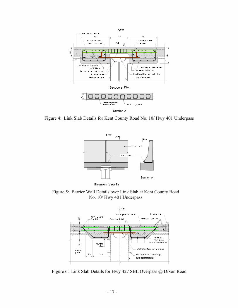
Figure 4: Link Slab Details for Kent County Road No. 10/ Hwy 401 Underpass
Figure 5: Barrier Wall Details over Link Slab at Kent County Road
No. 10/ Hwy 401 Underpass
150
180
Figure 6: Link Slab Details for Hwy 427 SBL Overpass @ Dixon Road
- 17 -

Figure 7: Barrier Wall Details over Link Slab at Hwy 427 SBL/Dixon Road Overpass
Figure 8: Semi-Continuous Girder Details for Uttoxeter Road/Hwy 402 Underpass
- 18 -
(a) Formwork inside Box Girder (b) Completed Concrete Diaphragm
Figure 9: Construction of Concrete Diaphragm Linking Simple Spans
dL2EIM θ=
Figure 10: Design Moment for Debonded Link Slab
Figure 11: Removal of Strip of Deck Slab at Pier
Figure 12: Debonded Link Slab Details for Orford Road/Hwy 401 Underpass
- 19 -

Figure 13: Membrane Reinforcement & Crack Control Details
(a) Reinforcement Continuity
Provided by Mechanical Couplers (b) Prefabricated Link Slab Panel showing
Expansion Joint in Parapet Wall
Precast Link Slab Panel
Figure 14: Prefabricated Link Slab Details for Mull Road/ Hwy 401 Underpass
(a) Formwork at Soffit of Link Slab (b) Concrete Pour for Link Slab
Figure 15: Construction of Debonded Link Slab at Camlachie Road/Hwy 402 Underpass
- 20 -

![Concrete One-way Slabs - Timber design...Concrete One-way Slabs By using the [Concrete Member] design module linked to the [Analysis] design module, one-way slabs can be designed](https://img.dokumen.tips/doc/110x75/6128234cdce56b427c583dcd/concrete-one-way-slabs-timber-design-concrete-one-way-slabs-by-using-the-concrete.jpg)