Embed Size (px)
Citation preview
General rights Copyright and moral rights for the publications made accessible in the public portal are retained by the authors and/or other copyright owners and it is a condition of accessing publications that users recognise and abide by the legal requirements associated with these rights.
• Users may download and print one copy of any publication from the public portal for the purpose of private study or research. • You may not further distribute the material or use it for any profit-making activity or commercial gain • You may freely distribute the URL identifying the publication in the public portal
If you believe that this document breaches copyright please contact us providing details, and we will remove access to the work immediately and investigate your claim.
Downloaded from orbit.dtu.dk on: Aug 31, 2018
Development of a Three-Dimensional Viscous-Inviscid coupling Method for WindTurbine Computations
Ramos García, Néstor; Sørensen, Jens Nørkær; Shen, Wen Zhong
Published in:Proceedings of the 2013 International Conference on aerodynamics of Offshore Wind Energy Systems andwakes (ICOWES2013)
Publication date:2013
Link back to DTU Orbit
Citation (APA):Ramos García, N., Sørensen, J. N., & Shen, W. Z. (2013). Development of a Three-Dimensional Viscous-Inviscid coupling Method for Wind Turbine Computations. In W. Z. Shen (Ed.), Proceedings of the 2013International Conference on aerodynamics of Offshore Wind Energy Systems and wakes (ICOWES2013) (pp.69-81). Technical University of Denmark (DTU).
ICOWES2013 Conference 17-19 June 2013, Lyngby
DEVELOPMENT OF A THREE-DIMENSIONALVISCOUS-INVISCID COUPLING METHOD FOR WIND
TURBINE COMPUTATIONS
Nestor Ramos Garcıa , Jens Nørkær Sørensen and Wen Zhong ShenDepartment of Wind Energy, Fluid Mechanics Section, Building 403,
Technical University of Denmark, DK-2800 Lyngby Denmark,
E-mail: [email protected]
June 7, 2013
Abstract
MIRAS, a computational model for predicting the aerodynamic behavior of wind tur-bine blades and wakes subject to unsteady motions and viscous effects has been developed.The model is based on a three-dimensional panel method usinga surface distribution ofquadrilateral singularities with a Neumann no penetrationcondition. Viscous effects insidethe boundary layer are taken into account through the coupling with the quasi-3D integralboundary layer solverQ3UIC. A free-wake model is employed to simulate the vorticityreleased by the blades in the wake. In this paper simulationsare presented in an effort tovalidate the code for three different rotor geometries, theMEXICO experiment rotor, theDELFT rotor and the NREL 5MW rotor.
1 Introduction
GPU and parallel computing, endless terabytes of memory, high speed connections, and otheraspects of computer resources have become more powerful and accessible in recent years. How-ever it is still behind our limits to use Navier-Stokes simulations for the design of wind turbinesdue to the large amount of computations involved in an optimization procedure. The free-wakevortex methods, extensively studied during the last four decades [1] [7] [2] [3], are now a ma-ture tool with the potential to become the new generation of fast-tools for analysis and designof wind turbines. This type of code permits a direct interaction between the design procedureand the blade geometry (CAD) with a low computational cost. Unlike Navier-Stokes codes thatneed to solve the entire flow domain, panel methods can simulate the flow arounda complexgeometry by distributing singularity elements on the body surface. Panel methods become evenmore attractive by the possibility of solving the integral boundary layer equations and take intoaccount the viscous effects using the transpiration velocity concept [4].
Wind turbine wake is a key element in the performance of rotor blade aerodynamics, havinga strong influence in the rotor plane. From an engineering point of view, the free-wake vortex

ICOWES2013 Conference 17-19 June 2013, Lyngby
approach is suitable to accurately model the inviscid phenomena that drivesthe general char-acteristics of the flow in the rotor wake, including the blade root and tip vortices, which arethe most dominant structures in the wake. The basic free-wake vortex filament method consistof infinitely thin vortex filaments. To avoid numerical singularities, previous researchers haveapplied a viscous core model, modeling in this way a more physical distribution ofthe velocitiesinduced by each one of the vortex filaments that forms the wake, desingularizing in this way theBiot-Savart law near the center of the filament, [8]. The diffusive time scales can be representedby changes in the vortex core radius as a function of the vortex age, using a turbulence eddy vis-cosity parameter [15]. Other improvements in the viscous core model include the introductionof changes in vortex strength due to filament stretching or squeezing, Ananthan and Leishman[9].
It is known that the viscous effects are important in the area surroundingthe body surface,the boundary layer, playing a key role in the blade aerodynamics, especially at high angles ofattack just before and after separation takes place. During the last decades simplified approachesto resolve the boundary layer equations have been developed by many researchers. In the two-dimensional case, panel methods have evolved to include viscous effectsby solving the boundarylayer in an integral manner, [10], [11] and [12] amongst others. Recently the Quasi-3D UnsteadyInteractive CodeQ3UIC was developed by Ramos-Garcıa et al. [5] [6] to take into account therotational effects arising from Coriolis and centrifugal forces. In the three-dimensional case,various researchers have previously implemented a viscous-inviscid coupling using the striptheory approach. Cebeci et al[20] combined a three-dimensional panel method with an inversefinite-difference boundary layer solver. Pesonen et al [21] and Lemmerman et al [22] coupled athree-dimensional panel method with an integral boundary layer solver. To the knowledge of theauthors the present method has not yet been applied for the study of windturbine aerodynamicsand its wake dynamics.
In the present work a zonal viscous-inviscid coupling method is developed in which theinviscid part is composed by a three-dimensional panel method with a free-wake model, theviscous effects confined inside the boundary layer are computed with the integral boundary layersolverQ3UIC. This viscous-inviscid interactive code will be referred asMIRAS, Methodfor viscous-inviscid Interactive Rotor Aerodynamic Simulations. In what follows MIRAS isused to simulate the DELFT and MEXICO wind turbine model rotors and the NREL5MWvirtual rotor, simulated aerodynamic forces and wake velocities have beencompared againstexperiments and Navier-Stokes simulations.
2 Governing equations
A wind turbine rotor is usually composed by two or three blades, their rotation generates a spiralvortex wake convected downstream. The rotor wake is formed by strong vortex structures andhas a large impact in the aerodynamics of the rotor itself. To simulate the flow around a windturbine rotor, we use a viscous-inviscid coupling method where the inviscid flow around thewind turbine rotor is solved using a panel method to simulate the blades, in which the viscouseffects are taken into account by theQ3UIC code. The wake is modeled by vortex filaments
ICOWES2013 Conference 17-19 June 2013, Lyngby
released at the blades trailing edges in form of straight lines and convected downstream usingthe Biot-Savart law.
In the following paragraphs the theory behind this approach will be introduced briefly. Formore detailed information about the model, the the reader is referred to Ramos-Garcia et al [5][6].
For a potential flow around a solid body with surfaceS, the velocity at a pointP in the flowdomain can be expressed as a superposition of the undisturbed translatingvelocity,U
∞, and the
disturbance velocity created by the solid body,Up, resulting in
U I = U∞
+ Up (1)
If the flow is considered to be incompressible, inviscid and irrotational,Up can be expressed as
Up = −∇φ (2)
whereφ is a potential function that satisfies the Laplace equation
∇2φ = 0 (3)
As the solid body surfaceS is impermeable, the normal component of the velocity must be zeroat the wall which gives a Neumann condition of no penetration across the body
∂φ
∂n= ∇φ · n = U
∞· n (4)
In practice, the problem is considered in two regions, the solid body and thedownstreamwake. The body is simulated by a distribution of quadrilateral surface dipoles,µ, and quadrilat-eral sources,σ. An extra source distribution,σwT , equal to the transpiration velocity computedwith Q3UIC, is introduced to account for viscous effects confined inside the boundary layer.The first row of wake elements is simulated using quadrilateral panel dipoleswhile further down-stream the panels are converted into wake elements formed by straight line vortex filaments,Γ.
∇Φ =−1
4π
∫
b
(σ + σwT )∇
(
1
r
)
+1
4π
∫
b
µ∇
[
∂
∂n
(
1
r
)]
+1
4π
∫
w
Γ∇
[
∂
∂n
(
1
r
)]
+∇Φ∞
(5)The vortex wake is released at the bodies trailing edges using the unsteadyKutta-Joukowsky
condition of zero trailing edge loading. To satisfy this condition, at each time step a quadrilateralpanel with a doublet distribution is created as the first wake panel for each one of the span-wisestations. The strength of these panels,Γfst, is equal to the difference between the correspondingupper and lower trailing edge quadrilateral doublets
Γfst = µu− µ
l(6)
Following Katz and Plotkin [7] the first wake panel is convected downstream from the trail-ing edge with a30% of the local undisturbed velocity. Downstream of the first row of wakepanels the quadrilateral doublets are transformed into vortex filaments and clustered into vortex

ICOWES2013 Conference 17-19 June 2013, Lyngby
elements. The strength of the vortex filaments remains constant in time with their motionrepre-sented by Lagrangian fluid markers placed at its end points which are convencted downstreamwith the total velocityu
u = u∞
+ ubody + uwake (7)
whereu∞
is the freestream velocity,ubody is the influence of the solid body anduwake isthe induction created by the other wake elements.
The velocity induced by the wake vortex filaments is computed by applying the Biot-Savartlaw. In order to desingularize its behavior asr tends to zero the Biot-Savart formula is modifiedfollowing Leishman et al. [13]. Where a viscous core is applied to all the released vortexfilaments during the time updating procedure. Therefore, an approximation toviscous diffusion,vortex core growth and vortex straining is included modifying the Biot-Savart law as follows
uwake = KΓ
4π
dl× r
|r|3(8)
where K is the kernel parameter, which uses the Scully profile account for the vortex filamentviscous core [14]. To include the core growth rate, Squire model is applied by introducing theturbulent eddy viscosity parameter [15]. Following Bhagwat and Leishmana straining model hasbeen implemented to take into account the change in vortex filament radius due toits variationsin length, stretching or squeezing [16].
Once the wake updating procedure is finalized, the new solution for the solidbody singu-larities is calculated. Knowing the doublets,µ, the local inviscid perturbation velocities arecalculated using a nodal interpolation of the doublets strength. Finally, the unsteady Bernoulliequation is used to compute the surface pressure on each one of the rotorblades,
∂φ
∂t+
1
2|v|2 +
1
ρp = +
1
ρpref
(9)
Viscous-inviscid coupling
The viscous boundary layer is solved by using the in-houseQ3UIC code. Q3UIC is anaerodynamic tool developed to solve the quasi three-dimensional integralboundary layer equa-tions, [5] [6]. The model is based on a viscous-inviscid interaction technique using strong cou-pling between the viscous and inviscid parts. InQ3UIC, the inviscid part is solved using atwo-dimensional potential flow panel method and the viscous effects are taken into account bysolving the integral form of the boundary layerr− andθ− momentum equations with extensionfor three-dimensional rotational effects created by Coriolis and centrifugal forces.
The r andθ integral momentum boundary layer equations can be written in terms of theboundary layer edge velocity,ue, and the integral boundary layer parametersθ1, θ2, δ
∗
1, δ∗
2, δ, δ3, H,Cf
andβw as:

ICOWES2013 Conference 17-19 June 2013, Lyngby
∂θ1∂s
= −1
u2e
d
dt(ueδ
∗
1)−∂θ1ue
∂ue∂s
(2 +H) +Cf
2+ swpr
2ROl
uecδ∗2 (10)
∂θ2∂s
= −2θ2ue
∂ue∂s
+ tanβwCf
2−
1
ue
∂ue∂r
(2δ3 + δ)
+l
c
(
θ1 + δ∗1 − δ − δ3 + swpr2RO
ue(δ − δ∗1)
)
(11)
In the laminar flow region, the solution of the integral form of ther− momentum Equa-tion 10 is obtained using Twaites’ method while in turbulent flow region, the solution of theintegral form of ther− andθ−momentum Equations 10 and 11 is carried out using a set ofthree dimensional turbulent closure relations for the streamwise and spanwise boundary layervariables.
The coupling between the viscous and inviscid parts inMIRAS is done locally for eachof the spanwise stations through the transpiration function using the angle ofattack calculatedupstream the blades leading edge to set the viscous computations.Q3UIC is used to computethe boundary layer parameters and obtain the chordwise distribution of the transpiration veloc-ity at the center line of the discrete spanwise sections.Q3UIC computations are performedfor the given sectional airfoil geometry at the calculated angle of attack using the followingnon-dimensional parameters: Reynolds number,Re =
√
(Ωr)2 + (Qw)2 c/ν, ratio betweenrotational speed and relative velocity,RO = Ωr/Urel and ratio between chord length and radialposition,l = c/r.
The transpiration velocity is computed using the following expression,
wT =1
ρ
∂
∂s(ρueδ
∗
1) (12)
wT is introduced in the three dimensional panel method as a source distribution, which actsblowing outwards the limiting streamlines, mimicking the effect of a viscous boundary layeraround the blade contour.
3 Results
In this section results obtained with theMIRAS code for the DELFT model rotor, the MEXICOrotor and the virtual NREL 5MW rotor will be presented.
DELFT model rotor
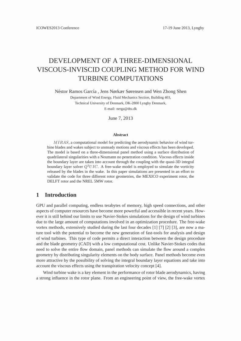
In this sectionMIRAS simulations of flows past the DELFT model rotor, Figure 1, are com-pared against hot-film measurements performed by Sant [17] in the open jet wind tunnel of DelftUniversity of Technology. The two bladed DELFT rotor has a radius of0.6m. The blade has aconstant chord of0.08 m and varying twist angle, constructed using NACA 0012 airfoil alongthe full blade span. The incoming wind speed in the presented simulations is5.5 ms−1 while
ICOWES2013 Conference 17-19 June 2013, Lyngby
the blades are rotating at a constant angular velocity of73.3 s−1. A surface mesh consisting of20 spanwise cells and50 chordwise cells has been used for theMIRAS simulations.
00.5
11.5
−0.50
0.5
−0.8
−0.6
−0.4
−0.2
0
0.2
0.4
0.6
0.8
xy
z
(a)
00.5
11.5
−0.50
0.5
−0.8
−0.6
−0.4
−0.2
0
0.2
0.4
0.6
0.8
xy
z(b)
Figure 1: The wake behind the DELFT rotor atTSR = 7.96 (a) full free wake (b) tip vortexfilaments.
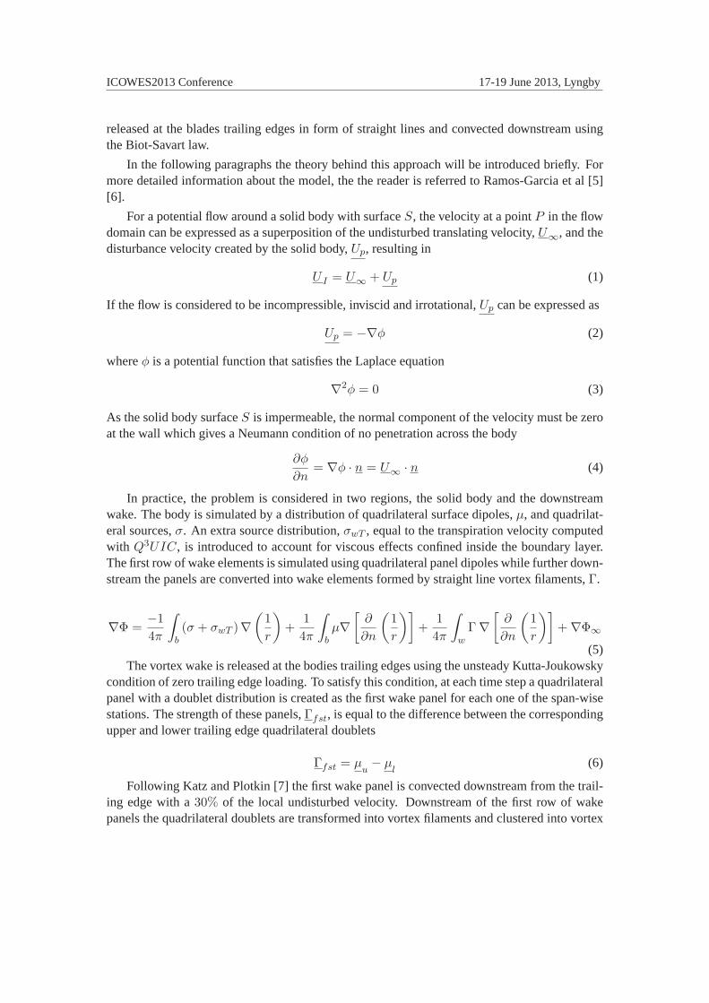
In Figure 2, the viscous and inviscid axial velocity predictions computed withMIRASare compared against measurements at distances of3.5 cm and9 cm downstream of the rotorplane at a radial location of0.6R along the azimuthal direction from0 to 360 degrees. Smalldifferences arise between the viscous and inviscid simulations, and the viscous solution is closerto experimental data at the3.5 cm locations and vice versa at9 cm. Simulations capture prettywell the axial velocity step created by the passage of the blade at the azimuthal positions of180and360 degrees.
0 50 100 150 200 250 300 350
−4
−3
−2
−1
0
1
Azimuth Angle [o]
Axi
al In
duce
d V
eloc
ity [m
/s]
EXPMIRAS Inv.MIRAS Vis.
(a)
0 50 100 150 200 250 300 350
−4
−3
−2
−1
0
1
Azimuth Angle [o]
Axi
al In
duce
d V
eloc
ity [m
/s]
EXPMIRAS Inv.MIRAS Vis.
(b)
Figure 2: Axial induced velocity along the azimuthal direction at (a)3.5 cm and (b)9 cmdownstream of the rotor and a radial location of0.6R.
In Figure 3,MIRAS predictions are compared against the measurements performed at a

ICOWES2013 Conference 17-19 June 2013, Lyngby
radial location of0.9R and two downstream positions. Calculated induced velocities are in goodagreement with measurements at the3.5 cm location, implying therefore that the correct rotorloading was predicted. Larger differences can be appreciated at9cm, where inviscid simulationsare closer to experiments. The more concentrated tip vortices computed in simulations andperhaps a deficient prediction of the wake filaments development near the tipregion could giverise to such increasing mismatches between viscous, inviscid simulations and experiments withthe downstream location. The use of a finer angular and spanwise discretization or even anadaptative mesh approach could improve the vortex roll-up characteristics.
0 50 100 150 200 250 300 350
−4
−3
−2
−1
0
1
Azimuth Angle [o]
Axi
al In
duce
d V
eloc
ity [m
/s]
EXPMIRAS Inv.MIRAS Vis.
(a)
0 50 100 150 200 250 300 350
−4
−3
−2
−1
0
1
Azimuth Angle [o]
Axi
al In
duce
d V
eloc
ity [m
/s]
EXPMIRAS Inv.MIRAS Vis.
(b)
Figure 3: Axial induced velocity along the azimuthal direction at (a)3.5 cm and (b)9 cmdownstream of the rotor and a radial location of0.9R.
The calculated wake vortex filaments for the viscous simulations presented above are shownin Figure 4. The influence of the wake passage crossing through the hot-film sampling vicinityis clearly seen at the0.9R locations around 180 and 360 degrees, although its influence diminishwith the decreasing radial location due to the weaker vortices shed in that region.
Figure 4: Calculated wake filaments for the DELFT rotor including hot-film location.

ICOWES2013 Conference 17-19 June 2013, Lyngby
MEXICO model rotor
A further validation of the viscous and inviscid versions of theMIRAS code is carried out forflows past the MEXICO rotor, Figure 5. In what follows the blade normal and tangential forcesare compared against measurements and wake velocities are validated against PIV experimentaldata.
The MEXICO experiment was executed on a three-bladed wind turbine model with a diam-eter of4.5m under controlled conditions in the Large Scale Low Speed Facility of the German-Dutch Wind tunnel Organization DNW with a9.5 X 9.5 m2 open test section. The test casesconsidered here are the rotor rotating with a constant angular speed of424.5rpm at wind speedsof 10, 15 and24 ms−1. The blades are subjected in all the three cases to a negative collectivepitch of δ0 = −2.3. Instantaneous velocities were extracted in a plane at 9 o’clock when look-ing downstream at the rotor when the first blade pointed upwards. For more detailed informationabout the MEXICO experiment campaign the reader is referred to Schepers and Snel [18].
A surface mesh consisting of20 spanwise cells and50 chordwise cells was used forMIRASsimulations. Laminar to turbulent transition was forced at a5% of the chord from the leadingedge on both the upper and lower sides of the airfoil sections.
(a)
0 1 2 3 4 5
−20
2
−2
−1
0
1
2
xy
z
(b)
Figure 5: MEXICO rotor atTSR = 6.67 (a) full free wake (b) Tip vortex filaments.
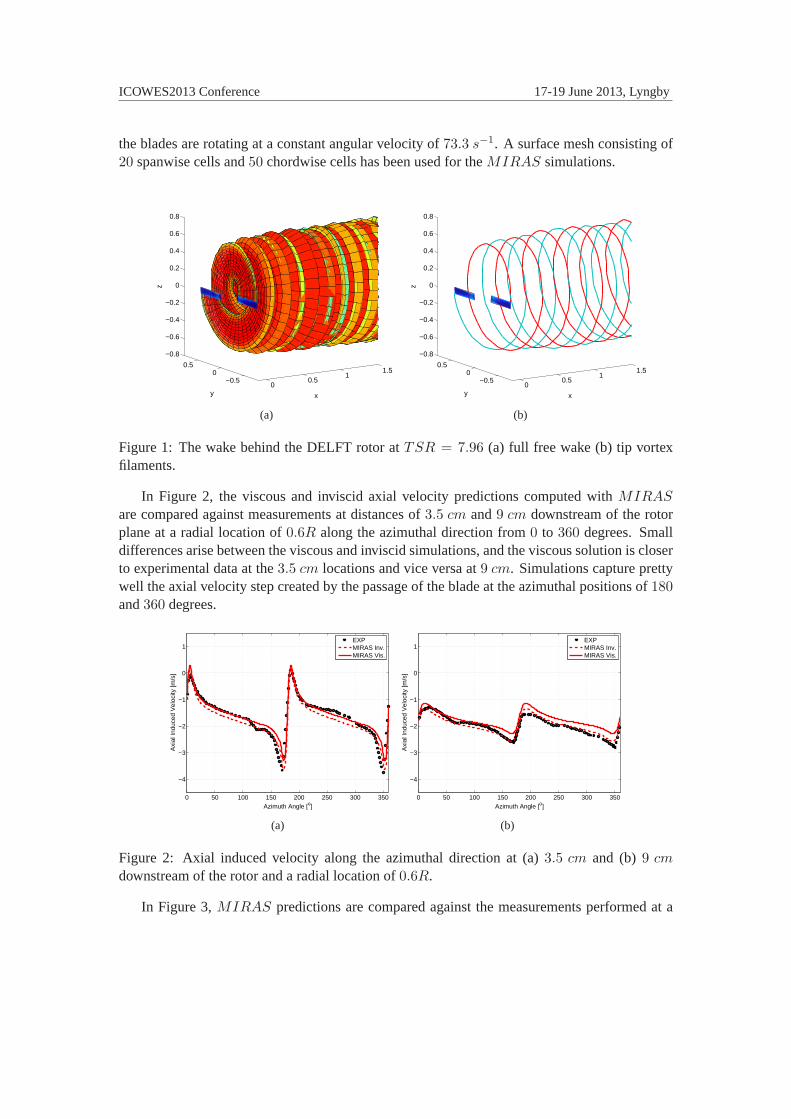
In Figure 6, the predictions of the normal an tangential blade forces are compared againstexperimental values for the wind speeds cases of10, 15 and24 ms−1. As the wind speed in-creases the inviscid computations predict higher values of both normal andtangential forceswhile the viscous simulations are in much better agreement with experiments, except in the rootregion where rotational effects arising from Coriolis and centrifugal forces seem to be underpre-dicted. At24ms−1 differences between the viscous and inviscid predictions are enormous,thisis related to the existence of regions with trailing edge separation.
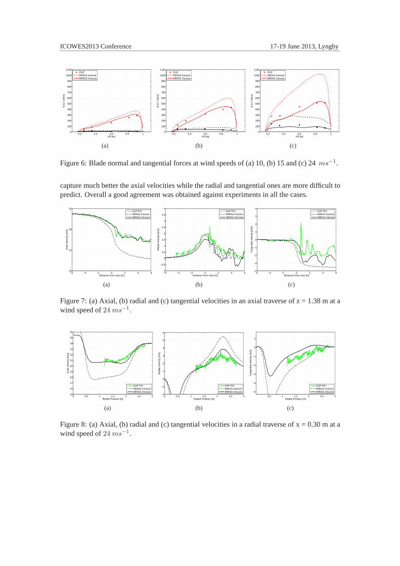
In Figures 7 and 8MIRAS viscous and inviscid predicted velocities are compared againstPIV measurements in axial and radial traverses for a wind speed of24ms−1. Viscous simulations
ICOWES2013 Conference 17-19 June 2013, Lyngby
0.2 0.4 0.6 0.8 10
100
200
300
400
500
600
700
800
900
1000
1100
r/R [m]
N &
T (
N/m
)
EXPMIRAS InviscidMIRAS Viscous
(a)
0.2 0.4 0.6 0.8 10
100
200
300
400
500
600
700
800
900
1000
1100
r/R [m]
N &
T (
N/m
)
EXPMIRAS InviscidMIRAS Viscous
(b)
0.2 0.4 0.6 0.8 10
100
200
300
400
500
600
700
800
900
1000
1100
r/R [m]
N &
T (
N/m
)
EXPMIRAS InviscidMIRAS Viscous
(c)
Figure 6: Blade normal and tangential forces at wind speeds of (a) 10,(b) 15 and (c) 24ms−1.
capture much better the axial velocities while the radial and tangential ones are more difficult topredict. Overall a good agreement was obtained against experiments in allthe cases.
−6 −4 −2 0 2 4 610
15
20
25
Distance from rotor [m]
Axi
al v
eloc
ity [m
/s]
EXP PIVMIRAS InviscidMIRAS Viscous
(a)
−6 −4 −2 0 2 4 6−1
−0.5
0
0.5
1
1.5
2
2.5
3
3.5
4
Distance from rotor [m]
Rad
ial v
eloc
ity [m
/s]
EXP PIVMIRAS InviscidMIRAS Viscous
(b)
−6 −4 −2 0 2 4 6−4
−3
−2
−1
0
1
2
3
4
Distance from rotor [m]
Tan
gent
ial v
eloc
ity [m
/s]
EXP PIVMIRAS InviscidMIRAS Viscous
(c)
Figure 7: (a) Axial, (b) radial and (c) tangential velocities in an axial traverse of z = 1.38 m at awind speed of24ms−1.
0 0.5 1 1.5 2 2.5 315
16
17
18
19
20
21
22
23
24
25
26
Radial Position [m]
Axi
al v
eloc
ity [m
/s]
EXP PIVMIRAS InviscidMIRAS Viscous
(a)
0 0.5 1 1.5 2 2.5 3−2
−1
0
1
2
3
4
5
6
Radial Position [m]
Rad
ial v
eloc
ity [m
/s]
EXP PIVMIRAS InviscidMIRAS Viscous
(b)
0.5 1 1.5 2 2.5 3
−5
−4
−3
−2
−1
0
1
Radial Position [m]
Tan
gent
ial v
eloc
ity [m
/s]
EXP PIVMIRAS InviscidMIRAS Viscous
(c)
Figure 8: (a) Axial, (b) radial and (c) tangential velocities in a radial traverse of x = 0.30 m at awind speed of24ms−1.

ICOWES2013 Conference 17-19 June 2013, Lyngby
NREL 5 MW virtual rotor
In this sectionMIRAS simulations are compared against Navier-Stokes computations forthe NREL 5 MW virtual wind turbine. The CFD computations were carried out using theEllipSys3D code in fully turbulent mode with thek − ω SST turbulence model [19]. Themesh used by EllipSys3D is a cylindrical mesh of4.2 · 106 mesh points which covers a domainwith a radius of245 m and inlet and outlet located at287 m in front and behind the rotor. Asurface mesh consisting of20 spanwise cells and50 chordwise cells has been used in this caseand14 wake revolutions were simulated with an angular discretization of10.
The wake calculated inMIRAS simulations, Figure 9, shows an important wake expansionand it can be appreciated how the interaction between the vortex sheets breaks the smooth shapeof the wake as it moves downstream. This effect is clearly observed whenfollowing the vortexfilaments released from the blades tip, Figure 9(b). After two wake revolutions the blade to bladefilament interaction grows and generates a vortex pairing phenomena whichmakes the filamentstangle with each other as they move further downstream.
(a)
050
100−50
050
−60
−40
−20
0
20
40
60
xy
z
(b)
Figure 9: (a) Full free wake (b) Tip vortex filaments of flows pass the NREL 5MW rotor at aTSR = 6.65.
Predicted normal and tangential forces are compared for the cases at wind speeds of6ms−1
and10ms−1, Figures 10 and 11. In terms of normal forcesMIRAS viscous predictions are inexcellent agreement with CFD data, while the inviscid ones are overpredicted as expected. Fromthe figures, it is seen that viscous simulations underpredict the tangential force near the bladetip region at the higher wind speed case,10 ms−1, although a better agreement is obtained at6ms−1.

ICOWES2013 Conference 17-19 June 2013, Lyngby
0 10 20 30 40 50 60 700
500
1000
1500
2000
2500
3000
3500
4000
4500
5000
r [m]
Nor
mal
forc
e [N
/ m
]
CFDMIRAS InviscidMIRAS Viscous
(a)
0 10 20 30 40 50 60 700
100
200
300
400
500
600
700
800
900
1000
r [m]
Tan
gent
ial f
orce
[N /
m]
CFDMIRAS InviscidMIRAS Viscous
(b)
Figure 10: (a) Normal and (b) tangential forces on the NREL 5MW blades. Viscous and inviscidMIRAS and Navier-StokesEllipSys3D simulations for6ms−1.
0 10 20 30 40 50 60 700
1000
2000
3000
4000
5000
6000
7000
8000
9000
10000
r [m]
Nor
mal
forc
e [N
/ m
]
CFDRPM InviscidRPM Viscous
(a)
0 10 20 30 40 50 60 700
500
1000
1500
r [m]
Tan
gent
ial f
orce
[N /
m]
CFDMIRAS InviscidMIRAS Viscous
(b)
Figure 11: (a) Normal and (b) tangential forces on the NREL 5MW blades. Viscous and inviscidMIRAS and Navier-StokesEllipSys3D simulations for10ms−1.
4 Conclusion
The MIRAS code, an unsteady three-dimensional panel method coupled with the integralboundary layer solverQ3UIC has been presented and validated against experiments and CFDsimulations for three different wind turbine rotors.
Near wake axial velocities computed withMIRAS have been compared with hot-film mea-surements for the DELFT model wind turbine obtaining a good agreement.
Computed axial, radial and tangential velocities have been validated againstMEXICO PIVmeasurements, as well as normal and tangential blade forces.
To conclude the study,MIRAS simulations of the virtual NREL 5 MW wind turbine havebeen compared against Navier-Stokes simulations in terms of blade forces,obtaining an excel-

ICOWES2013 Conference 17-19 June 2013, Lyngby
lent agreement for the normal forces and a fairly good comparison for the tangential ones.
5 Acknowledgements
We gratefully acknowledge the support from the Danish Council for Strategic Research forthe project ’Center for Computational Wind Turbine Aerodynamics and Atmospheric Turbu-lence’ (2104-09-067216/DSF), the Energy Technology Developmentand Demonstration Pro-gram (EUDP-2011-64011-0094) and the Danish Energy Agency (EUDP-2012-64012-0146).
References
[1] J.L. Hess 1971 Numerical solution of inviscid subsonic flowsVon Karman Institute for FluidDynamics, Lecture Series,34
[2] J. Katz 1985 Calculation of the Aerodynamic Forces on Automotive LiftingSurfacesTrans-actions of the ASME,107: 438–443
[3] L. Morino, Z. Kaprielian and S.R. Sipcic 1985 Free Wake Analysis of Helicopter RotorsVertica,9: 127–140
[4] M.J. Lighthill 1958 On displacement thicknessJournal of Fluid Mechanics, vol. 4, pp. 383-392
[5] N. Ramos-Garcıa 2011 Unsteady viscous-inviscid interaction technique for wind turbine air-foils PhD. Thesis, Technical University of Denmark, Department of Mechanical Engineering,ISBN 978-87-90416-53-9
[6] N. Ramos-Garcıa, W.Z. Shen and J.N. Sørensen 2013 A Strong Viscous-Inviscid InteractionModel for Rotating AirfoilsSubmitted to Wind energy
[7] J. Katz and A. Plotkin 1977 Low speed aerodynamicsMcGraw-Hill, second edition
[8] J.G. Leishman 2000 Principles of Helicopter AerodynamicsCambridge University Press
[9] S. Ananthan and J.G. Leishman 2004 Role of Filament Strain in the Free-Vortex Modelingof Rotor WakesJournal of the American Helicopter Society
[10] T. Cebeci, M. F. Platzer, H. M. Jang and H. H. Chen 1993 An inviscid-viscous interactionapproach to the calculation of dynamic stall initiation on airfoilsJournal of Turbomachinery,115: 714-723
[11] J. N. Sørensen 1988 Prediction of Separated FLow Past Airfoil using Viscous-InviscidInteraction TechniqueLa Recherche Aerosptatiale 1-11

REFERENCESICOWES2013 Conference 17-19 June 2013, Lyngby
[12] M. Drela and M. B. Giles 1987 Viscous-inviscid analysis of transonicand low Reynoldsnumber airfoilAIAA journal25: 1347–1355
[13] J.G. Leishman, M.J. Bhagwat and A. Bagai 2002 Free-Vortex Filament Methods for theAnalysis of Helicopter Rotor WakesJournal of Aircraft5: 759–775
[14] M.P. Scully 1975 Computation of Helicopter Rotor Wake Geometry and Its Influence onRotor Harmonic AirloadsPh.D. Thesis, Massachusetts Institute of Technology. Dept. of Aero-nautics and Astronautics
[15] H.B. Squire 1965 The growth of a vortex in turbulent flowAeronautical Quarterly16:302–306
[16] M.J. Bhagwat and J.G. Leishman 2001 Accuracy of Straight-Line Segmentation Appliedto Curvilinear Vortex FilamentsJournal of the American Helicopter Society46:2:166-169
[17] T. Sant 2007 Improving BEM-base Aerodynamic Models in Wind Turbine Design CodesPhD Thesis, ISBN: 978-99932-0-483-1, Delft University Wind EnergyResearch Institute
[18] J.G. Scheepers and H. Snel 2007 Model Experiments in Controlled Conditions Final Re-port The Energy Research Center of the Netherlands The Energy Research Center of theNetherlands
[19] W.Z. Shen, W.J. Zhu, J.N. Sørensen, N.N. Sørensen and P.E. Rethore 2012 Study of tiploss corrections using CFD rotor computationsThe Science of Making Torque from Wind,Oldenburg
[20] T. Cebeci, D. Sedlock, K.C. Chang and R.W.Clark 1988 Analysis of Wings with FlowSeparationJournal of Aircraft,26:3:214-220
[21] U.J. Pesonen, R.K. Agarwal and S. Laine 2000 Fast and RobustViscous/Inviscid Interac-tion Code for Wing Flowfield CalculationsJournal of Aircraft,37:4:730-733
[22] L.A. Lemmerman and V.R. Sonnad 1979 Three-Dimensional Viscous-Inviscid CouplingUsing Surface TranspirationJournal of Aircrfact,16:6:353-358