Embed Size (px)
Citation preview
Contract No. CONCRETE BASE
AUS-SPEC-1\NSW-C248 Jun 98 (Copyright) KEMPSEY SHIRE COUNCIL
DEVELOPMENT CONSTRUCTION SPECIFICATION
C248
PLAIN OR REINFORCED
CONCRETE BASE
Contract No. CONCRETE BASE
AUS-SPEC-1\NSW-C248 Jun 98 (Copyright) KEMPSEY SHIRE COUNCIL
Amendment Record for this Specification Part
This Specification is Council’s edition of the AUS-SPEC generic specification part and includes Council’s primary amendments.
Details are provided below outlining the clauses amended from the Council edition of this AUS-SPEC Specification Part. The clause numbering and context of each clause are preserved. New clauses are added towards the rear of the specification part as special requirements clauses. Project specific additional script is shown in the specification as italic font.
The amendment code indicated below is ‘A’ for additional script ‘M’ for modification to script and ‘O’ for omission of script. An additional code ‘P’ is included when the amendment is project specific.
Amendment Sequence No.
Key Topic addressed in amendment
Clause No.
Amendment Code
Author Initials
Amendment Date
EXAMPLE 1
Provision for acceptance of nonconformance with deduction in Payment
XYZ.00 AP KP 2/6/97
1 Measurement and Payment
Pay Items
C248.59 O JRM 17/10/00
Contract No. CONCRETE BASE
AUS-SPEC-1\NSW-C248 Jun 98 (Copyright) C248-1
KEMPSEY SHIRE COUNCIL
SPECIFICATION C248 PLAIN OR REINFORCED CONCRETE BASE
GENERAL
C248.01 SCOPE
1. The work to be executed under this Specification consists of the construction, by mechanical or hand placement of plain or reinforced concrete base, including trial sections, slab anchors and terminal slabs to the dimensions and levels shown on the Drawings and in accordance with the provisions of the Contract.
2. The work also includes the construction of reinforced concrete approach slabs at bridge abutments and traffic signal approach slabs where specified on the Drawings.
Approach Slabs
C248.02 THICKNESS AND LEVELS OF BASE
1. The base thickness and levels shall be shown on the Drawings.
C248.03 REFERENCE DOCUMENTS
1. Documents referenced in this specification are listed in full below whilst being cited in the text in the abbreviated form or code indicated.
Documents Standards Test Methods
(a) Council Specifications C224 - Open Drains including Kerb and Gutter C231 - Subsoil and Foundation Drains C247 - Mass Concrete Subbase
(b) Australian Standards AS 1012.1 - Sampling fresh concrete. AS 1012.3 - Determination of properties related to the consistence of
concrete. AS 1012.4 - Determination of air content of freshly mixed concrete. AS 1012.8 - Making and curing concrete compression, indirect tensile
and flexure test specimens in the laboratory or in the field. AS 1012.9 - Determination of the compressive strength of concrete
specimens. AS 1012.12 - Determination of mass per unit volume of hardened
concrete. AS 1012.13 - Determination of the drying shrinkage of concrete for
samples prepared in the field or in the laboratory. AS 1012.14 - Securing and testing cores from hardened concrete for
compressive strength or indirect tensile strength. AS 1141.11 - Particle size distribution by dry sieving. AS 1141.14 - Particle shape by proportional calliper. AS 1141.18 - Crushed particles of coarse aggregates. AS 1141.22 - Wet/dry strength variation. AS 1141.24 - Soundness (by use of sodium sulphate solution). AS 1160 - Bitumen emulsions for construction and maintenance of
pavements. AS 1302 - Steel reinforcing bars for concrete. AS 1303 - Steel reinforcing wire for concrete.
CONCRETE BASE Contract No.
C248-2 AUS-SPEC-1\NSW-C248 Jun 98 (Copyright)
KEMPSEY SHIRE COUNCIL
AS 1304 - Welded wire reinforcing fabric for concrete. AS 1379 - The specification and manufacture of concrete. AS 1478 - Chemical admixtures in concrete. AS 1554.3 - Welding of reinforcing steel. AS 2758.1 - Concrete aggregates. AS 3582.1 - Supplementary Ccmentitious materials - flyash. AS 3799 - Liquid membrane - forming curing compounds for concrete. AS 3972 - Portland and blended cement.
(c) RTA Test Methods T 1160 - Low Temperature Recovery of Preformed Polychloroprene
Elastomeric Joint Seals for Bridge Structures. T 1161 - High Temperature Recovery of Polychloroprene Elastomeric
Joint Seals for Bridge Structures. T 1163 - Resistance of Vulcanised Rubber to the Absorption of Oil. T1192 - Adhesion of Sealant. T1193 - Accelerated Ageing of Cured Sealant.
(d) ASTM Standards D792 - Test Method for Specific Gravity (Relative Density) and
Density of Plastics by Displacement. C793 - Test Method for Effects of Accelerated Weathering on
Elastomeric Joint Sealants. C794 - Test Method for Adhesion-in-Peel of Elastomeric Joint
Sealants. D2240 - Test Method for Rubber Property Durometer Hardness. D2628 - Specification for Preformed Polychloroprene Elastomeric
Joint Seals for Concrete. D2835 - Specification for Lubricant for Installation of Preformed
Compression Seal in Concrete Pavements.
(e) US Military Specifications MIL-S-8802 - Sealing Compound, Temperature Resistant, Integral Fuel
Tanks and Fuel Cell Cavities, High Adhesion.
MATERIALS FOR CONCRETE
C248.04 CEMENT
1. Cement shall be Type GP Portland cement complying with AS 3972 and shall be from a source included in the New South Wales Government Cement Quality Assurance Scheme.
NSW QA Scheme
2. When submitting details of the nominated mix in accordance with Clause C248.19 the Contractor shall nominate the brand and source of the cement. On approval of a nominated mix by the Superintendent, the Contractor shall use only the nominated cement in the work.
Nominated Brand and Source
3. Documentary evidence of the quality and source of the cement shall be furnished by the Contractor to the Superintendent upon request at any stage of the work.
Proof of Quality
4. If the Contractor proposes to use cement which has been stored for a period in excess of three months from the time of manufacture, a re-test shall be required to ensure the cement still complies with AS 3972, before the cement is used in the work.
Storage Time
5. The cost of re-testing the cement shall be borne by the Contractor and results of the testing forwarded to the Superintendent.
Contractor’s Cost
Contract No. CONCRETE BASE
AUS-SPEC-1\NSW-C248 Jun 98 (Copyright) C248-3
KEMPSEY SHIRE COUNCIL
6. Cement shall be transported in watertight containers and shall be protected from moisture until used. Caked or lumpy cement shall not be used.
Transport and Storage
C248.05 FLYASH
1. Flyash shall be from a source included in the New South Wales Government Cement Quality Assurance Scheme. The use and quality of flyash shall comply with AS 3582.1.
NSW QA Scheme
2. When submitting details of the nominated mix in accordance with Clause C248.19, the Contractor shall nominate the powerhouse source of the flyash. The Contractor shall use only flyash from the nominated powerhouse.
Source
3. Documentary evidence of the quality and source of the flyash shall be furnished by the Contractor to the Superintendent.
Documentary Evidence
C248.06 WATER
1. Water used in the production of concrete shall be potable, free from materials harmful to concrete or reinforcement, and be neither salty nor brackish.
Quality
C248.07 ADMIXTURES
1. Chemical admixtures and their use shall comply with AS 1478. Admixtures shall not contain calcium chloride, calcium formate, or triethanolamine or any other accelerator. Admixtures or combinations of admixtures other than specified below, shall not be used. An air-entraining agent shall be included in the mix and the air content of the concrete shall comply with Clause C248.13.
Quality and Use
2. Fresh concrete with an air content not complying with Clause C248.13 shall be rejected.
Excess Air Content
3. During the warm season, (October to March inclusive), a lignin or lignin-based (`ligpol') set-retarding admixture (Type Re or Type WR Re) approved by the Superintendent shall be used to control slump within the limits stated in Clause C248.12. The dosage shall be varied to account for air temperature and haul time in accordance with the manufacturer's recommendations. A copy of the NATA endorsed Certificate of Compliance with AS 1478 for Type Re or Type WR Re shall be submitted to the Superintendent, together with the proposed `dosage chart' in accordance with Clause C248.19.
Retarder for Warm Season
4. During the cool season, (April to September inclusive), only a lignin or lignin based set-retarding admixture containing not more than 6 per cent reducing sugars (Type WR Re complying with AS 1478) may be used in the mix. If the Contractor proposes to vary the admixture between the warm and cool seasons such variation shall constitute a proposed change to an approved mix for the purposes of Clause C248.21.
Retarder for Cool Season
CONCRETE BASE Contract No.
C248-4 AUS-SPEC-1\NSW-C248 Jun 98 (Copyright)
KEMPSEY SHIRE COUNCIL
5. When submitting details of the nominated mix in accordance with Clause C248.19, the Contractor shall nominate the proprietary source, type and name for each admixture to be used. Documentary evidence of the quality shall be furnished by the Contractor to the Superintendent upon request at any stage of the work.
Source and Type
C248.08 AGGREGATES
(a) General
1. At least 40 per cent by mass of the total aggregates in the concrete mix shall be quartz sand. Quartz sand is aggregate having a nominal size of less than 5 mm and shall contain at least 70 per cent quartz, by mass. Where present, chert fragments will be regarded as `quartz' for the purpose of this specification, but the ratio of chert to quartz shall not exceed unity.
Quartz Sand Content
2. When submitting details of the nominated mix in accordance with Clause C248.19, the Contractor shall nominate the sources of aggregate to be used in the concrete and shall submit details of the geological type of each aggregate.
Source and Type
(b) Fine Aggregate
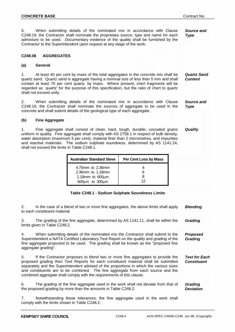
1. Fine aggregate shall consist of clean, hard, tough, durable, uncoated grains uniform in quality. Fine aggregate shall comply with AS 2758.1 in respect of bulk density, water absorption (maximum 5 per cent), material finer than 2 micrometres, and impurities and reactive materials. The sodium sulphate soundness, determined by AS 1141.24, shall not exceed the limits in Table C248.1.
Quality
Australian Standard Sieve Per Cent Loss by Mass
4.75mm to 2.36mm 2.36mm to 1.18mm 1.18mm to 600µm 600µm to 300µm
4 6 8 12
Table C248.1 - Sodium Sulphate Soundness Limits
2. In the case of a blend of two or more fine aggregates, the above limits shall apply to each constituent material.
Blending
3. The grading of the fine aggregate, determined by AS 1141.11, shall be within the limits given in Table C248.2.
Grading
4. When submitting details of the nominated mix the Contractor shall submit to the Superintendent a NATA Certified Laboratory Test Report on the quality and grading of the fine aggregate proposed to be used. The grading shall be known as the "proposed fine aggregate grading".
Proposed Grading
5. If the Contractor proposes to blend two or more fine aggregates to provide the proposed grading then Test Reports for each constituent material shall be submitted separately and the Superintendent advised of the proportions in which the various sizes and constituents are to be combined. The fine aggregate from each source and the combined aggregate shall comply with the requirements of this clause.
Test for Each Constituent
6. The grading of the fine aggregate used in the work shall not deviate from that of the proposed grading by more than the amounts in Table C248.2.
Grading Deviation
7. Notwithstanding these tolerances, the fine aggregate used in the work shall comply with the limits shown in Table C248.2.
Contract No. CONCRETE BASE
AUS-SPEC-1\NSW-C248 Jun 98 (Copyright) C248-5
KEMPSEY SHIRE COUNCIL
Australian Standard Sieve
Proportion Passing (% of Mass of
Sample)
Deviation from Proposed Grading
(% of Mass of Sample)
9.50mm 4.75mm 2.36mm 1.18mm 600µm 300µm 150µm 75µm
100 90 - 100 65 - 95 40 - 80 24 - 52 8 - 25 1 - 8 0 - 3
± 3 ± 10 ± 10 ± 10 ± 5 ± 2
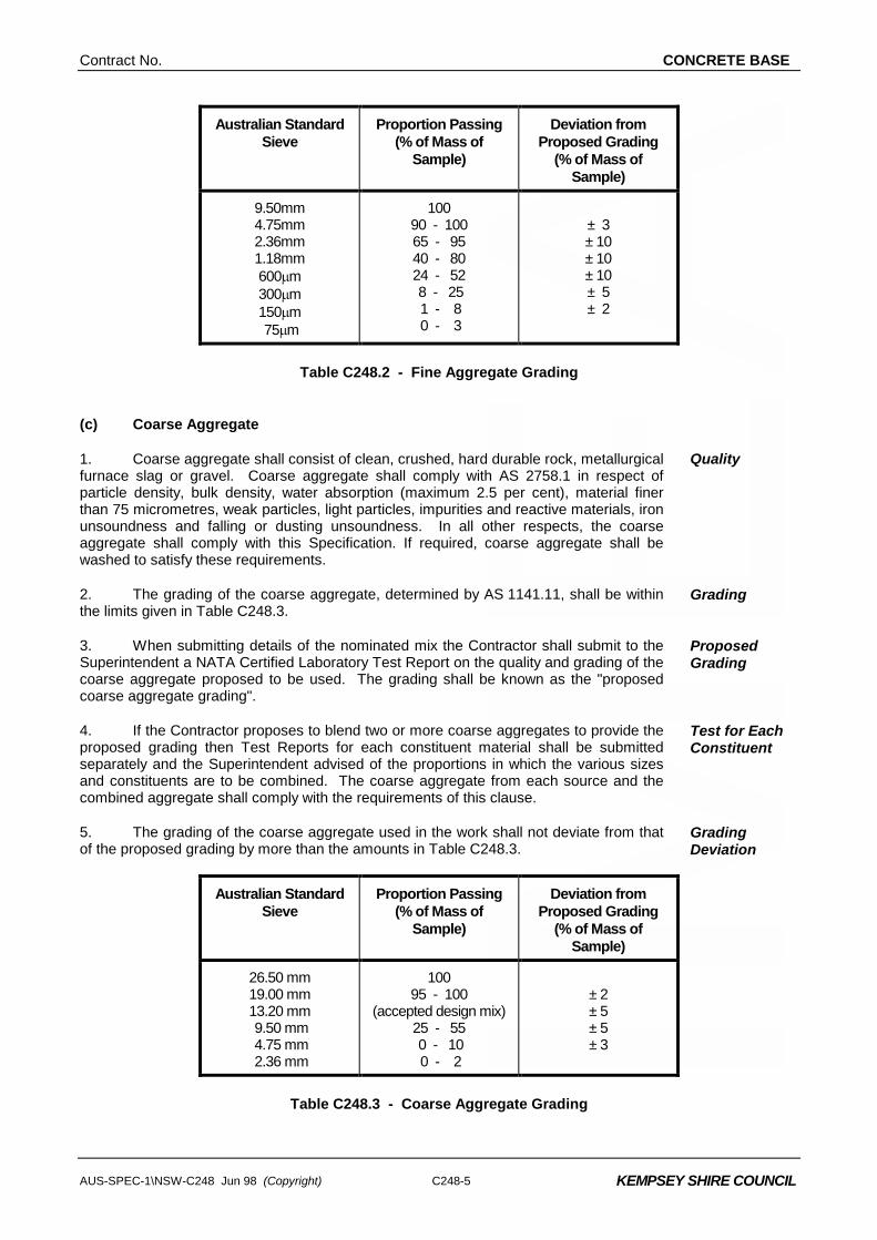
Table C248.2 - Fine Aggregate Grading
(c) Coarse Aggregate
1. Coarse aggregate shall consist of clean, crushed, hard durable rock, metallurgical furnace slag or gravel. Coarse aggregate shall comply with AS 2758.1 in respect of particle density, bulk density, water absorption (maximum 2.5 per cent), material finer than 75 micrometres, weak particles, light particles, impurities and reactive materials, iron unsoundness and falling or dusting unsoundness. In all other respects, the coarse aggregate shall comply with this Specification. If required, coarse aggregate shall be washed to satisfy these requirements.
Quality
2. The grading of the coarse aggregate, determined by AS 1141.11, shall be within the limits given in Table C248.3.
Grading
3. When submitting details of the nominated mix the Contractor shall submit to the Superintendent a NATA Certified Laboratory Test Report on the quality and grading of the coarse aggregate proposed to be used. The grading shall be known as the "proposed coarse aggregate grading".
Proposed Grading
4. If the Contractor proposes to blend two or more coarse aggregates to provide the proposed grading then Test Reports for each constituent material shall be submitted separately and the Superintendent advised of the proportions in which the various sizes and constituents are to be combined. The coarse aggregate from each source and the combined aggregate shall comply with the requirements of this clause.
Test for Each Constituent
5. The grading of the coarse aggregate used in the work shall not deviate from that of the proposed grading by more than the amounts in Table C248.3.
Grading Deviation
Australian Standard Sieve
Proportion Passing (% of Mass of
Sample)
Deviation from Proposed Grading
(% of Mass of Sample)
26.50 mm 19.00 mm 13.20 mm 9.50 mm 4.75 mm 2.36 mm
100 95 - 100
(accepted design mix) 25 - 55 0 - 10 0 - 2
± 2 ± 5 ± 5 ± 3
Table C248.3 - Coarse Aggregate Grading
CONCRETE BASE Contract No.
C248-6 AUS-SPEC-1\NSW-C248 Jun 98 (Copyright)
KEMPSEY SHIRE COUNCIL
6. Notwithstanding these tolerances, the coarse aggregate used in the work shall comply with the limits shown in Table C248.3.
7. The coarse aggregate shall also conform to the following requirements:-
(i) Wet Strength - AS 1141.22.
Shall not be less than 80 kN for any fraction and/or constituent.
Additional Tests
(ii) 10 per cent Fines Wet/Dry Variation - AS 1141.22.
Shall not exceed 35 per cent for any fraction and/or constituent.
(iii) Soundness - AS 1141.24
The loss in mass when tested with sodium sulphate shall not exceed 9 per cent for any constituent.
(iv) Particle Shape - AS 1141.14
The proportion of misshapen particles (2:1 ratio) shall not exceed 35 per cent.
(v) Fractured Faces - AS 1141.18.
At least 80 per cent by mass of the particles shall have two or more fractured faces.
(d) Storage
1. Storage and handling facilities shall be such as to prevent the aggregates becoming intermixed or mixed with foreign materials, and to prevent segregation occurring.
Facilities
2. The area surrounding the storage facilities and mixing plant shall be so constructed that delivery vehicles, loaders and trucks shall not be capable of introducing foreign matter to the aggregates at any time. If foreign matter is introduced or the area reaches a condition where, in the opinion of the Superintendent, foreign matter may be introduced to the aggregates, production of concrete and delivery of materials shall cease until the condition is corrected to the satisfaction of the Superintendent.
Introduction of Foreign Matter
QUALITY REQUIREMENTS OF CONCRETE
C248.09 CEMENT AND FLYASH CONTENT
1. The minimum Portland cement content shall be 270 kilograms per yielded cubic metre of concrete. The maximum flyash content shall be 50 kilograms per yielded cubic metre of concrete.
Cement and Flyash
C248.10 COMPRESSIVE STRENGTH
1. The compressive strength of concrete shall be determined in accordance with AS 1012.9. The minimum compressive strength at twenty-eight days shall be 36.0 MPa.
Compressive Strength
Contract No. CONCRETE BASE
AUS-SPEC-1\NSW-C248 Jun 98 (Copyright) C248-7
KEMPSEY SHIRE COUNCIL
C248.11 SHRINKAGE
1. The drying shrinkage of the nominated mix, determined by AS 1012.13, shall not exceed 450 microstrain after three weeks air drying. The drying shrinkage at the nominated slump plus 10 mm shall be taken as the average of the reading or readings within 5 per cent of the median of the three readings obtained in accordance with AS 1012.13.
Shrinkage Limit
C248.12 CONSISTENCY
1. The Contractor's nominated slump, determined in accordance with AS 1012.3, Method 1, shall be neither less than 30 mm nor more than 40 mm for mechanically placed concrete and shall be neither less than 55 mm nor more than 65 mm for hand placed concrete.
Slump Tolerance
C248.13 AIR CONTENT
1. The air content of the concrete, determined in accordance with AS 1012.4, Method 2, shall be neither less than 4 per cent nor more than 7 per cent, when discharged from the transport vehicle ready for placement.
Tolerances
STEEL REINFORCEMENT
C248.14 MATERIAL
1. Steel reinforcement shall comply with the requirements of the appropriate following Australian Standards:-
(a) AS 1302 Steel Reinforcing Bars for Concrete.
(b) AS 1303 Steel Reinforcing Wire for Concrete.
(c) AS 1304 Welded Wire Reinforcing Fabric for Concrete.
Standards
2. The type and size of bars shall be as shown on the Drawings. Type and Size
3. Steel reinforcement shall be free from loose or thick rust, grease, tar, paint, oil, mud, millscale, mortar or any other coating, but shall not be brought to a smooth polished condition.
Quality
4. The Contractor shall supply evidence satisfactory to the Superintendent that steel reinforcement complies with AS 1302, AS 1303 or AS 1304, as appropriate. Test certificates shall show the results of mechanical tests and chemical analysis.
Documentary Evidence
5. Where the material cannot be identified with a test certificate, samples shall be taken and testing arranged by the Contractor. The samples shall be selected randomly and consist of three specimens each at least 1.2 m in length. The cost of all samples and tests shall be borne by the Contractor.
Sampling
Contractor’s Cost
6. Plastic bar chairs or plastic tipped wire chairs shall be capable of withstanding a load of 200kg mass on the chair for one hour at 23 ± 5oC without malfunction. The Contractor shall demonstrate that the proposed chairs conform with these requirements.
Wire Chairs
CONCRETE BASE Contract No.
C248-8 AUS-SPEC-1\NSW-C248 Jun 98 (Copyright)
KEMPSEY SHIRE COUNCIL
C248.15 BENDING
1. Reinforcement shall be formed to the dimensions and shapes shown on the Drawings. Reinforcement shall not be bent or straightened in a manner that will damage the material. Bars with kinks or bends not shown on the Drawings shall not be used. Heating of reinforcement for purposes of bending will only be permitted if uniform heat is applied. Temperature shall not exceed 450oC and the heating shall extend beyond the portion to be bent. Heated bars shall not be cooled by quenching.
Bending
C248.16 SPLICING
1. All reinforcement shall be furnished in the lengths indicated on the Drawings. Except where shown on the Drawings, splicing of bars shall only be permitted with the approval of the Superintendent as to the location and method of splicing.
The length of lapped splices not shown on the Drawings shall be as follows for unhooked bars:- Plain bars, Grade 250 - 40 bar diameters Deformed bars, Grade 400 - 35 bar diameters Hard-drawn wire - 50 bar diameters
Plan Lengths
2. Splices in reinforcing fabric shall be measured as the overlap between the outermost wire in each sheet of fabric transverse to the direction of splice. This overlap shall not be less than the pitch of the transverse wires plus 25 mm.
Splice Dimensions
3. In welded splices, bars shall only be welded by an approved electrical method. Grade 400 deformed bars shall not be welded.
Welded Splice
4. Welding shall comply with AS 1554.3. The welded splice shall meet requirements of tensile and bend tests specified for the parent metal.
Welding Standard
C248.17 STORAGE
1. Reinforcement, unless promptly incorporated into the concrete, shall be stored under a waterproof cover and supported clear of the ground, and shall be protected from damage and from deterioration due to exposure.
Protection of Reinforcement
C248.18 PLACING
1. Reinforcing bars and wire reinforcing fabric shall be accurately placed to the dimensions and details shown on the Drawings. They shall be securely held by blocking from the forms, by supporting on concrete or plastic chairs or metal hangers, as approved by the Superintendent, and by wiring together where required using annealed iron wire not less than 1.25 mm diameter. These supports shall be in a regular grid not exceeding 1 m and steel shall not be supported on metal supports which extend to any surface of the concrete, on wooden supports, nor on pieces of aggregate.
Position
2. Tack welding instead of wire ties may be used on reinforcing steel. Cold-worked reinforcing bars shall not be tack welded.
Tack Welding
3. The minimum cover of any bar to the nearest concrete surface shall be 50 mm unless otherwise shown on the Drawings.
Bar Cover
4. Tie bars shall be placed in the pavement such that after placement they remain in their specified location. Tie bars shall not be placed through the finished upper surface of the pavement. Tie bars shall be placed either ahead of paving or by a bar vibrator into the edge of the joint or by an automatic tie bar inserter on the mechanical paver. Irrespective
Tie Bars
Contract No. CONCRETE BASE
AUS-SPEC-1\NSW-C248 Jun 98 (Copyright) C248-9
KEMPSEY SHIRE COUNCIL
of the method of placement, tie bars extending from any side face of base concrete or gutter shall be anchored in a manner which will develop 85 per cent of the yield strength of the bar in tension.
5. Placing and fastening of all reinforcement in the work shall be approved by the Superintendent before concrete is placed and adequate time shall be allowed for inspections and any corrective work which the Superintendent may require. Notice for inspection shall not be less than four working hours before the intended time of commencement of concrete placement or such time as determined by the Superintendent.
Inspection
DESIGN AND CONTROL OF CONCRETE MIXES
C248.19 GENERAL
1. The Contractor shall submit, for approval by the Superintendent, details of the concrete mix (or mixes) and the materials, including source, to be used for each of mechanically placed and hand placed base, including nominated slump and moisture condition of the aggregates (oven dry, saturated surface dry, or other specified moisture content) on which the mix is based. Each such mix shall be known as a 'nominated mix'.
Nominated Mix
2. Also, the Contractor shall provide a Certificate from a laboratory with appropriate NATA registration stating that each nominated mix and its constituents meet the requirements of this Specification. All relevant test results shall accompany the Certificate. All phases of any particular test must be performed at one laboratory. The certificate shall confirm that the required testing has been carried out in the twelve month period before the date of submission to the Superintendent.
Certified Test Results
3. In the tests supporting the above certification, the compressive strength gain curve shall be submitted showing the compressive strengths at ages 3, 7, 10 and 28 days determined in accordance with AS1012.9. Each of the results shall be based on three specimens of concrete produced from a batch of the nominated mix. The compressive strength shall be the average of individual results within 2.0 MPa of the median. The compressive strength for 28 days shall not be less than 36.0 MPa.
Compressive Strength
4. These details shall be submitted at least 21 days before using the nominated mix in the work.
Submission of Details
C248.20 VARIATIONS TO APPROVED MIXES
1. The Contractor shall not make any changes to the approved mix, its method of production or source of supply of constituents without the prior written approval of the Superintendent.
Approval for Mix Variation
2. Where changes to an approved mix are proposed, the Contractor shall provide details of the nominated mix and materials, in accordance with Clause C248.19. If the variations to the quantities of the constituents in the approved mix are less than 10 kg for Portland cement and flyash and 5 per cent by mass for each other constituent, except admixtures, per yielded cubic metre of concrete the Superintendent may approve the changes without new trials being carried out.
Contractor's Responsibility
3. Notwithstanding these tolerances the minimum Portland cement content shall be 270 kilograms per yielded cubic metre of concrete and the maximum flyash content shall be 50 kilograms per yielded cubic metre of concrete.
Content per Cubic Metre
CONCRETE BASE Contract No.
C248-10 AUS-SPEC-1\NSW-C248 Jun 98 (Copyright)
KEMPSEY SHIRE COUNCIL
CONFORMANCE OF CONCRETE STRENGTH, COMPACTION AND THICKNESS
C248.21 CONCRETE CYLINDERS
(a) Test Specimens
1. Test specimens for determining the compressive strength of concrete shall be standard cylinders complying with AS 1012.8. The Contractor shall supply a sufficient number of moulds to meet the requirements for the frequency of testing specified in this Clause and shall also arrange for a laboratory with appropriate NATA registration to conduct the sampling of fresh concrete and the making, curing, delivery and testing of specimens. Copies of test results shall be forwarded to the Superintendent.
Contractor's Responsibility
2. Samples of concrete for testing shall be taken in accordance with AS1012.1. The selection of the batches to be sampled shall be taken randomly. The specimens shall be moulded from each sample so that they are as identical as practicable.
Sampling
3. The method of making and curing specimens shall be in accordance with AS1012.8 with compaction by internal vibration.
Curing
4. The Contractor shall mark the specimens for identification purposes. Marking
5. The cost of all work and material required in the making, curing, delivery and testing of specimens shall be borne by the Contractor.
Contractor’s Cost
(b) Frequency of Moulding of Test Specimens
1. Test specimens shall be moulded as follows:-
Moulding of Cylinders
(i) For the determination of the compressive strength at twenty-eight days. For each lot of up to 50 cubic metres of concrete placed at the one time: One pair of specimens
(ii) For the determination of the compressive strength at seven days. For each lot of up to 50 cubic metres of concrete placed at the one time: One pair of specimens (iii) For the determination of compressive strength for any early testing as deemed
necessary by the Contractor. For each lot of up to 50 cubic metres of concrete placed at the one time: One pair of specimens
2. A lot is defined as a continuous pour of up to 50 cubic metres of concrete placed. Lot Size
(c) Inspection, Capping and Crushing of Specimens
1. Specimens required by this Specification shall be tested at the NATA registered laboratory nominated by the Contractor. The cost of such testing shall be borne by the Contractor.
Contractor’s Cost
2. Specimens shall be inspected, capped and crushed in accordance with AS1012.9.
Standards
3. Before crushing, the mass per unit volume of the seven day specimens shall also Mass Unit
Contract No. CONCRETE BASE
AUS-SPEC-1\NSW-C248 Jun 98 (Copyright) C248-11
KEMPSEY SHIRE COUNCIL
be determined in accordance with AS1012.12 Method 2, so that the relative compaction of cores taken from the same lot of concrete base can be determined.
Volume
C248.22 COMPRESSIVE STRENGTH OF CONCRETE
(a) General
1. The compressive strength of the concrete represented by a pair of specimens moulded from one sample shall be the average compressive strength of the two specimens unless the two results differ by more than 3.0 MPa, in which case the higher result shall be taken to represent the compressive strength of the lot of concrete.
Determination of Strength
(b) Adjustment of Test Compressive Strength for Age of Specimen
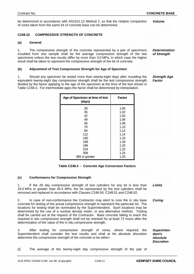
1. Should any specimen be tested more than twenty-eight days after moulding the equivalent twenty-eight day compressive strength shall be the test compressive strength divided by the factor applying to the age of the specimen at the time of the test shown in Table C248.4. For intermediate ages the factor shall be determined by interpolation.
Strength Age Factor
Age of Specimen at time of test (days)
Factor
28 35 42 49 56 70 84 112 140 168 196 224 308
365 or greater
1.00 1.02 1.04 1.06 1.08 1.10 1.12 1.14 1.16 1.18 1.20 1.22 1.24 1.25
Table C248.4 - Concrete Age Conversion Factors
(c) Conformance for Compressive Strength
1. If the 28 day compressive strength of test cylinders for any lot is less than 33.0 MPa or greater than 45.0 MPa, the lot represented by the test cylinders shall be removed and replaced in accordance with Clauses C248.50, C248.51 and C248.52.
Limits
2. In case of non-conformance the Contractor may elect to core the in situ base concrete for testing of the actual compressive strength to represent the particular lot. The locations for testing shall be nominated by the Superintendent. Such locations may be determined by the use of a nuclear density meter, or any alternative method. Testing shall be carried out at the request of the Contractor. Base concrete failing to reach the required in situ compressive strength shall not be retested for at least 72 hours after the determination of the value of the in situ compressive strength.
Coring
3. After testing for compressive strength of cores, where required, the Superintendent shall consider the test results and shall at his absolute discretion determine the compressive strength of the concrete to be either:-
Superinten-dent's Absolute Discretion
(i) The average of the twenty-eight day compressive strength of the pair of
CONCRETE BASE Contract No.
C248-12 AUS-SPEC-1\NSW-C248 Jun 98 (Copyright)
KEMPSEY SHIRE COUNCIL
specimens moulded at the time of placing; or
(ii) The equivalent twenty-eight day compressive strength of the core.
4. A lot is defined as a continuous pour of up to 50 cubic metres of base represented by a pair of test specimens cast from a sample of the concrete used in its construction.
Lot Size
C248.23 CONFORMANCE FOR THICKNESS
1. Thickness measurements of the concrete base shall be determined by survey, measurements at the edges or by coring. Audit checks using a suitable probe may be carried out whilst the concrete is being placed. The readings shall be rounded off to the nearest 5mm.
Thickness Measurement
2. Base which is below the specified thickness shall be removed and replaced in accordance with Clauses C248.50, C248.51 and C248.52.
Remove and Replace
3. Base which is thicker than the design thickness will be acceptable provided the finish satisfies the requirements of Clause C248.31.
C248.24 RELATIVE COMPACTION OF CONCRETE
(a) Test Specimens
1. Test specimens for determining the relative compaction of the concrete placed in the work shall be cores cut from the work. Cores shall be cut from the full depth of the concrete base to the requirements of AS 1012.14, with the following exceptions:-
(i) The requirement that the concrete shall be at least 28 days old before the core is removed shall not apply. However concrete must be not less than three days old in the warm season and six days old in the cool season, before removal.
(ii) The nominal diameter of the cores shall not be less than 75 mm.
Cores
2. The location of coring shall be chosen to exclude joints, steel reinforcement or tie bars from the core. The locations are not intended to be random, but are intended to ensure that the whole of the concrete base conforms to the minimum requirements of the Specification. Cores shall be marked for identification.
Location of Cores
3. Cores shall be placed immediately either in a tank of lime saturated water or in an individual plastic bag and sealed to prevent water loss. Cores stored in plastic bags shall be kept in the shade.
Storage
4. Cores shall not be subjected to temperatures in excess of either ambient temperature or 23oC whichever is the higher and they shall not be subjected to temperature less than 10oC, until delivered to the testing laboratory.
Temperature Control
(b) Frequency of Coring
1. The Contractor shall take a minimum of one core specimen from each lot of concrete base represented by standard cylinders moulded in accordance with Clause C248.21.
Minimum
2. In the case of hand-placed base concrete, two cores shall be taken to represent a section of work. A section of work shall be confined between construction joints. Hand-worked or placed base that is cast with machine-placed concrete and not separated from the machine-placed concrete shall be deemed to be part of the machine-placed concrete, and be cored and tested as part of the machine-placed concrete base.
Hand Placed Concrete
Contract No. CONCRETE BASE
AUS-SPEC-1\NSW-C248 Jun 98 (Copyright) C248-13
KEMPSEY SHIRE COUNCIL
(c) Repair of Core Holes
1. The Contractor shall clean and restore all core holes taken in the base with non-shrink cementitious concrete having a compressive strength of not less than that in the base and a maximum nominal aggregate size of 10 mm.
Contractor's Responsibility
2. The surface of the restored hole shall be similar to the surrounding surface in texture and colour.
Surface Condition
3. The cost of restoring core holes shall be borne by the Contractor. Contractor’s Costs
(d) Testing of Cores for Compaction
1. The core specimens shall be wet conditioned in accordance with AS 1012.14 for not less than 24 hours immediately prior to testing for compaction. Testing to determine mass per unit volume shall be carried out on specimens at age seven days.
Curing
2. The relative compaction of a core specimen shall be the ratio, expressed as a percentage, of the mass per unit volume of the core specimen to the average mass per unit volume of the standard cylinders used to determine the seven day compressive strength from the same lot of concrete base. The mass per unit volume of both standard cylinders and cores shall be determined in accordance with AS 1012.12 Method 2. All costs associated with obtaining, curing and testing of cores shall be borne by the Contractor.
Relative Compaction
Contractor’s Cost
(e) Conformance for Compaction
1. If the relative compaction is less than 97.0 per cent, the lot represented by the core shall be removed and replaced in accordance with Clauses C248.50, C248.51 and C248.52.
Rejection Percentage
2. Core specimens for compressive strength testing shall be wet-conditioned, prepared and tested in accordance with AS 1012.14. Cores obtained for compaction shall not be re-used for compressive strength testing.
Core Preparation
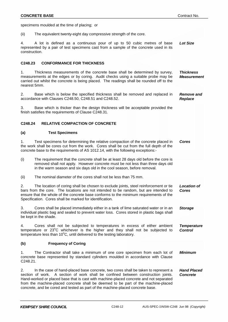
3. The test strength shall be adjusted for age at test in accordance with Clause C248.22 and for length/diameter ratio in accordance with Table C248.5 by multiplying by the correction factor in Table C248.5.
Adjustment for Age
4. If the 28 day compressive strength of the core is less than 33.0 MPa, the lot represented by the compaction core shall be removed and replaced in accordance with Clauses C248.50, C248.51 and C248.52.
Core Compressive Strength
Length/Diameter Ratio Correction Factor
2.00 1.00
1.75 0.98
1.50 0.96
1.25 0.93
1.00 0.89
Table C248.5 - Correction Factors
CONCRETE BASE Contract No.
C248-14 AUS-SPEC-1\NSW-C248 Jun 98 (Copyright)
KEMPSEY SHIRE COUNCIL
PRODUCTION, TRANSPORT AND CONSISTENCY OF CONCRETE
C248.25 PRODUCTION AND HANDLING OF CONCRETE
1. At least four weeks before commencing work under this Specification, the Contractor shall submit, for the information of the Superintendent, details of the proposed methods of handling, storing and batching materials for concrete, details of proposed mixers and methods of agitation, mixing and transport.
Contractor's Responsibility
2. The methods of handling, storing and batching materials for concrete shall be in accordance with AS 1379, with the following additional requirements:-
Handling and Batching Methods
(a) Certificates of Calibration issued by a recognised authority shall be made available for inspection by the Superintendent, as evidence of the accuracy of the scales.
(b) Cementitious material shall be weighed in an individual hopper, with the Portland cement weighed first.
(c) The moisture content of the aggregates shall be determined at least daily immediately prior to batching. Corresponding corrections shall be made to the quantities of aggregates and water.
3. Details of proposed mixers and agitation methods shall be in accordance with the plant and equipment sections of AS 1379, with the additional requirement that in Appendix A of AS 1379 the maximum permissible difference in slump shall be 10 mm.
Mixer
Requirements
C248.26 MIXING AND TRANSPORT
1. Mixing and transport methods shall be in accordance with the production and delivery sections of AS 1379, with the following additional requirements:-
Methods
(a) The mixer shall be charged in accordance with the manufacturer's instructions.
(b) For the purpose of conducting mixer uniformity tests in accordance with Appendix A of AS 1379 on a split drum mixer producing centrally mixed concrete, the whole of the batch shall be discharged into the tray of a moving vehicle. The concrete shall then be sampled from the tray of the vehicle at points approximately 15 per cent and 85 per cent along the length of the tray.
(c) For truck-mixed concrete, addition of water in accordance with the batch production section of AS 1379 shall be permitted only within ten minutes of completion of batching and within 200 m of the batching facilities. The delivery docket must clearly indicate the amount of water added, but in no circumstance shall the water : cement ratio be exceeded. Mixing of the concrete shall be completed at that location.
(d) Admixtures shall be separately prediluted with mixing water and shall be incorporated by a method which ensures that no adverse interaction occurs.
(e) After addition of the cement to the aggregate, concrete shall be incorporated into the work within:-
- One and a half hours, where transported by truck mixer or agitator;
- One hour, where transported by non-agitating trucks.
Means of verification, satisfactory to the Superintendent, of the times of
Contract No. CONCRETE BASE
AUS-SPEC-1\NSW-C248 Jun 98 (Copyright) C248-15
KEMPSEY SHIRE COUNCIL
addition of cement to the aggregate shall be provided. The times within which the concrete shall be incorporated into the work may be reduced if the Superintendent considers the prevailing weather, mix type, or materials being used warrant such a change.
(f) The size of the batch in an agitator vehicle shall not exceed the manufacturer's rated capacity nor shall it exceed 80 per cent of the gross volume of the drum of the mixer.
C248.27 MIXING TIME
1. Minimum mixing time will be as determined for the approved mix and verified when trial concrete base is constructed.
2. Where by reason of delay, it is necessary to hold a batch in the mixer, mixing may be continued for a maximum of ten minutes except for split drum mixers where the maximum shall be five minutes.
Batch in Mixer
3. For longer periods, the batch may be held in the mixer and turned over at regular intervals, subject to the time limits specified for incorporation of the concrete into the work not being exceeded.
Long Delays
C248.28 CONSISTENCY
1. At all times between mixing and discharge, the slump shall be within 10mm of the Contractor's nominated slump for the nominated mix for mechanically placed concrete and within 15mm thereof for hand placed concrete.
Tolerances
2. The consistency of the concrete shall be checked by use of a slump cone in accordance with AS1012.3 Method 1. The test shall be made on concrete samples obtained in accordance with AS1012.1.
Test Method
3. The consistency of the concrete shall be checked within 30 minutes of adding cement to the aggregate. If the actual haul time exceeds 45 minutes, the consistency shall also be checked immediately prior to discharge. Concrete which is non-conforming in relation to consistency shall not be incorporated into the work. Check tests shall be done on each truck load of concrete. The cost of consistency testing shall be borne by the Contractor.
Timing of Testing
Contractor’s Cost
4. Check tests shall be done on each truckload of concrete. Check Tests
PLACING AND FINISHING CONCRETE BASE
C248.29 GENERAL
1. At least four weeks before commencing work under this Specification, the Contractor shall submit as part of the Quality Plan, for the information of the Superintendent, full details of the equipment and methods proposed for placing and finishing the concrete base together with a paving plan showing proposed paving widths, sequence and estimated daily outputs.
Contractor's Responsibility
2. The Contractor shall give the Superintendent seven days written notice of the intention to commence construction of the base on any section of work (including the placement of the trial concrete base in accordance with Clause C248.39.
Written Notice
3. The subbase surface shall be clean and free of loose or foreign matter and prepared in accordance with the Specification for MASS CONCRETE SUBBASE – C247.
Subbase Condition
CONCRETE BASE Contract No.
C248-16 AUS-SPEC-1\NSW-C248 Jun 98 (Copyright)
KEMPSEY SHIRE COUNCIL
4. Concrete shall not be placed either during rain or when the air temperature in the shade is below 5°C or above 38°C.
Air Temperature
5. The temperature of the concrete at the point of discharge from transport vehicles shall be neither less than 10°C nor more than 32°C.
Concrete Temperature
6. Where required, slab anchors shall be constructed prior to construction of the base.
Slab Anchors
C248.30 RATE OF EVAPORATION
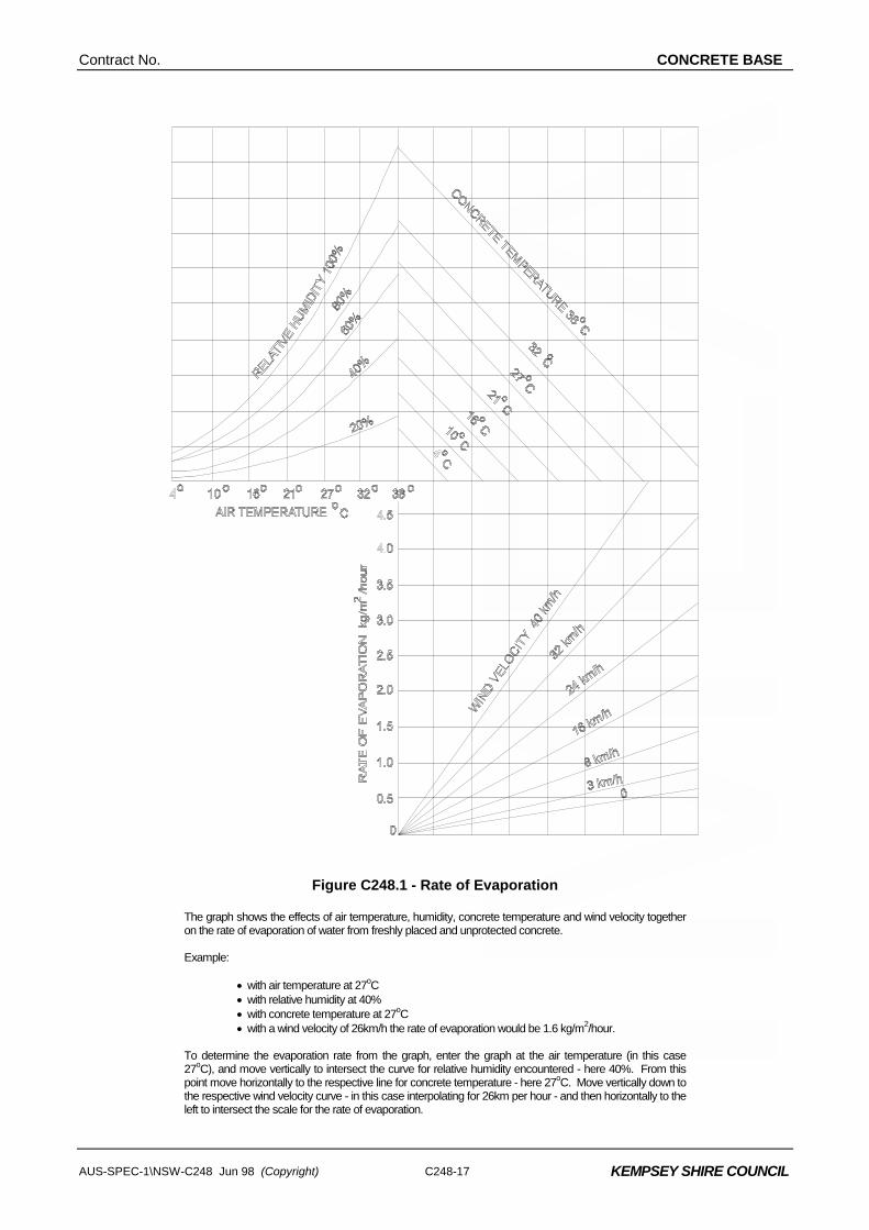
1. When the value of Rate of Evaporation, determined from the graph in Figure C248.1, exceeds 0.50 kilograms per square metre per hour the Contractor shall take precautionary measures satisfactory to the Superintendent for the prevention of excessive moisture loss. If, in the opinion of the Superintendent, such precautionary measures prove to be unsatisfactory, the Contractor shall cease work while the evaporation rate is in excess of 0.50 kilograms per square metre per hour.
Evaporation Limit
2. Should the Contractor elect to use an evaporation retarder to prevent excessive moisture loss, application shall be by fine spray after all finishing operations, except minor manual bull-floating, are complete.
Use of Retarder
3. The Contractor shall be responsible for measuring and recording concrete temperature and wind velocity at the point of concrete placement, and for continuously measuring and recording air temperature and relative humidity at the site throughout the course of the work. The Contractor shall provide and maintain all equipment and shall provide suitable personnel necessary for all such measuring and recording.
Contractor'sResponsibility
4. The cost of providing and maintaining such equipment, providing suitable personnel and taking precautionary measures for the prevention of excessive moisture loss shall be borne by the Contractor.
Contractor’s Costs
Contract No. CONCRETE BASE
AUS-SPEC-1\NSW-C248 Jun 98 (Copyright) C248-17
KEMPSEY SHIRE COUNCIL
Figure C248.1 - Rate of Evaporation The graph shows the effects of air temperature, humidity, concrete temperature and wind velocity together
on the rate of evaporation of water from freshly placed and unprotected concrete. Example: • with air temperature at 27oC • with relative humidity at 40% • with concrete temperature at 27oC • with a wind velocity of 26km/h the rate of evaporation would be 1.6 kg/m2/hour. To determine the evaporation rate from the graph, enter the graph at the air temperature (in this case
27oC), and move vertically to intersect the curve for relative humidity encountered - here 40%. From this point move horizontally to the respective line for concrete temperature - here 27oC. Move vertically down to the respective wind velocity curve - in this case interpolating for 26km per hour - and then horizontally to the left to intersect the scale for the rate of evaporation.
CONCRETE BASE Contract No.
C248-18 AUS-SPEC-1\NSW-C248 Jun 98 (Copyright)
KEMPSEY SHIRE COUNCIL
C248.31 MECHANICAL PAVING
1. The mechanical paver shall be a self-propelled machine with a gross operating mass of not less than 4 tonnes per lineal metre of paved width. It shall be capable of paving at a speed of one metre per minute or less as required to enable the continuous operation of the paver and obtain the required degree of compaction. It shall include the following features:-
Paving Machine
(a) An automatic control system with a sensing device to control line and level to the specified tolerances.
(b) Means of spreading the mix uniformly and regulating the flow of mix to the vibrators without segregation of the components.
(c) Internal vibrators capable of compacting the full depth of the concrete.
(d) Adjustable extrusion screed and/or conforming plate to form the slab profile and produce the required finish on all surfaces.
(e) Capability of paving in the slab widths or combination of slab widths and slab depths shown on the Drawings.
2. The mechanical paver shall spread, compact, screed and finish the freshly placed concrete in such a manner that a minimum of finishing by hand will be required. A dense and homogeneous concrete with a surface exhibiting low permeability, shall be provided. It shall be textured in accordance with Clause C248.34.
Concrete Finish
3. The supporting surface for the tracks of the paver, curing machine and any other equipment in the paving and curing train shall be in a smooth and firm condition.
Supporting Surface
4. Once spreading commences, the concrete paving operation shall be continuous. The mechanical paver shall be operated so that its forward progress shall not be stopped due to lack of concrete. If disruptions occur for any reason, the Superintendent may direct that a construction joint be formed before the recommencement of paving operations. The cost of forming such construction joint shall be borne by the Contractor.
Continuity of Paving Operation Contractor’s Cost
5. Where an interruption to paving occurs, which is likely to result in a non-monolithic concrete mass, the Contractor shall form a transverse construction joint in accordance with Clause C248.41.
Interruption to Paving
6. Should subsequent testing at the location of an interruption indicate the presence of non-monolithic concrete, such concrete shall be removed and replaced in accordance with Clauses C248.50, C248.51 and C248.52.
Non-monolithic Concrete
C248.32 HAND PLACING
1. Hand placement shall only be used in areas where mechanical placement is impracticable or where it has been approved by the Superintendent prior to commencement of work.
Restriction
2. Forms shall be so designed and constructed that they can be removed without damaging the concrete and shall be true to line and grade and braced in a substantial and unyielding manner. Forms shall be mortar tight and debonded to ensure non-adhesion of concrete to the forms.
Formwork
Contract No. CONCRETE BASE
AUS-SPEC-1\NSW-C248 Jun 98 (Copyright) C248-19
KEMPSEY SHIRE COUNCIL
3. Concrete shall be delivered in agitator vehicles and shall be deposited uniformly in the forms without segregation. The concrete shall be compacted by poker vibrators and by at least two passes of a hand-guided vibratory screed traversing the full width of the slab on each pass. Any buildup of concrete between the forms and vibratory screed shall be prevented.
Placing in Forms
4. If disruptions occur for any reason, the Superintendent may direct that a construction joint be formed before the recommencement of paving operations. The cost of forming such construction joint shall be borne by the Contractor.
Disruption, Contractor’s Cost
5. A dense and homogeneous concrete with a surface exhibiting low permeability, shall be provided. It shall be textured in accordance with Clause C248.34.
Concrete Finish
6. Where an interruption to placing occurs, which is likely to result in a non-monolithic concrete mass, the Contractor shall form a transverse construction joint in accordance with Clause C248.41.
Transverse Construction Joint
7. Should subsequent testing at the location of an interruption indicate the presence of non-monolithic concrete, such concrete shall be removed and replaced in accordance with Clauses C248.50, C248.51 and C248.52.
Non-Monolithic Concrete
C248.33 ALIGNMENT AND SURFACE TOLERANCES
(a) Horizontal Alignment Tolerance
1. The outer edges of the base shall be square to the subbase and shall not deviate from the plan position at any point by more than 10 mm.
Outer Edge
2. Where an edge of a slab is to form a longitudinal joint line the allowable horizontal alignment tolerances shall comply with Clause C248.46.
Longitudinal Joint Line
(b) Tolerances and Rideability
1. The tolerance on thickness of the base shall be zero below the specified thickness and in accordance with Clause C248.23 for excess thickness.
Top of Base Level
2. The top surface of the base shall also not deviate from a 3 m straightedge, laid in any direction, by more than 5 mm. Notwithstanding this requirement, the surface shall not pond water.
Surface Level
C248.34 TEXTURING OF SURFACE
1. Texturing of the concrete surface may be effected by use of a fine broom or hessian-drag. The Contractor shall submit to the Superintendent details of the proposed texturing method and equipment.
C248.35 CURING
1. The base shall be cured by the use of one of the following:
(a) Chlorinated rubber curing compound complying with AS 3799 Class C Type 1D or resin-based curing compound complying with AS 3799 Class B, Type 1D or Type 2, if an asphalt wearing surface is used, or
(b) White pigmented wax emulsion curing compound complying with AS 3799 Class A Type 2, if no asphalt wearing surface is used, or
(c) Bitumen emulsion Grade CRS/170 complying with AS 1160 for either
Compounds
CONCRETE BASE Contract No.
C248-20 AUS-SPEC-1\NSW-C248 Jun 98 (Copyright)
KEMPSEY SHIRE COUNCIL
asphalt wearing or no asphalt wearing surface.
2. The Contractor shall submit, for the information of the Superintendent, a current Certificate of Compliance from an Australian laboratory, approved by the Superintendent, showing an Efficiency Index of not less than 90 per cent when tested in accordance with Appendix B of AS 3799.
Efficiency Index
3. The curing compound shall be applied using a fine spray immediately following texturing at the rate stated on the Certificate of Compliance or at a minimum of 0.2 litres per square metre, whichever rate is the greater. Bitumen emulsion shall be applied at a minimum rate of 0.5 litres per square metre. When applied with an hand lance the rates shall be increased by 25 per cent.
4. The average application rate shall be checked by the Contractor and certified to the Superintendent by calculating the amount of curing compound applied to a measured area representative of a lot and nominated by the Superintendent.
Application Rate
5. The curing membrane shall be maintained intact for seven days after placing the concrete. Any damage to the curing membrane shall be made good by handspraying of the affected areas.
Curing Period
6. The cost of making good such damaged curing membrane shall be borne by the Contractor.
Contractor’s Cost
7. Equipment and materials for curing operations shall be kept on site at all times during concrete pours.
Equipment on Site
C248.36 PROTECTION OF WORK
1. The Contractor shall ensure that the temperature of the concrete does not fall below 5°C during the first twenty-four hours after placing. The Contractor shall provide, for the information of the Superintendent, details of procedures and equipment proposed to be used for the protection of sections recently placed in the event of low air temperatures. If the Contractor fails to maintain the temperature of the concrete at or above 5°C and if, in the opinion of the Superintendent, the concrete exhibits any deficiencies, due to failure to comply with this Specification, the concrete shall be rejected.
Temperature Control
2. The Contractor shall protect the work from rain damage and shall provide, for the information of the Superintendent, detailed proposals for procedures and equipment to be used for such protection.
Rain Protection
3. Neither traffic nor construction equipment, other than that associated with testing, sawcutting, groove cleaning or joint sealing, shall be allowed on the finished base until the joints have been permanently sealed and at least 10 days have elapsed since placing concrete, and the concrete has reached a compressive strength of at least 20MPa.
Traffic Restrictions
C248.37 ODD-SHAPED AND MISMATCHED SLABS
1. A slab is a portion of concrete base bounded by joints or free edges. A slab shall be considered to be odd-shaped if the ratio of the longer dimension to the shorter dimension exceeds 1.6 or if the joint pattern produces an angle of less than 80 degrees between two adjacent sides. Slab dimensions shall be taken as the average dimension measured normal and parallel to the longitudinal joints. Slabs containing blockouts for drainage structures shall be considered as odd-shaped.
Definition
2. Where any joint meets a slab and is not continued across that slab, that slab shall be considered a mismatched slab.
Contract No. CONCRETE BASE
AUS-SPEC-1\NSW-C248 Jun 98 (Copyright) C248-21
KEMPSEY SHIRE COUNCIL
3. Unless otherwise shown on the Drawings, odd-shaped and mismatched slabs shall be reinforced with F82 reinforcing fabric placed with 50 mm to 60 mm cover to the surface of the base. Fabric shall be clear of all transverse and longitudinal joints by 50 mm to 100 mm.
Reinforcing Fabric
C248.38 TERMINAL SLABS
1. Terminal slabs shall be constructed adjoining bridge approach slabs and at changes from a rigid pavement to a flexible pavement. Terminal slabs shall be constructed to the dimensions and details shown on the Drawings.
Position
C248.39 TRIAL CONCRETE BASE
1. Before the commencement of paving, the Contractor shall construct a trial section of concrete base on the carriageway to demonstrate to the Superintendent the Contractor's capability of constructing base in accordance with the Specification. This section shall be constructed so that it may be incorporated in the finished work.
Location
2. The trial base shall be constructed using the same materials, concrete mix, equipment and methods the Contractor intends to use for the remaining base work. The Contractor shall demonstrate the methods proposed to be used for texturing, the application of curing compound, the construction and sawing of joints and the placement of tie bars and dowels.
Purpose
3. The trial shall also be used to demonstrate that the Contractor's allowances for concrete strength, compaction and slab thickness are adequate to achieve the minimum requirements specified.
Quality Parameters
4. A trial length of between 20m and 100m for mechanical paving equipment or between 10m and 30m for hand placement is required. The maximum width proposed to be laid, shall be constructed in one continuous operation.
Dimensions
5. Unless advised by the Superintendent of any deficiencies in the trial concrete base, due to failure to comply with this Specification, the Contractor may proceed with placing concrete base from a time ten working days after the completion of the trial concrete base or such earlier time as the Superintendent may allow. In the event of deficiencies in the trial concrete base, the Superintendent may order the Contractor to construct a further length of trial concrete base which shall be treated as the first. If, after three trials, the base still is deficient in some way, the Superintendent may require the Contractor to justify to the satisfaction of the Superintendent why the work should be allowed to continue using that method and/or equipment and/or materials and/or personnel.
Deficiencies in Trial Section
6. The Superintendent shall have the right to call for a new trial section at any stage of work under the contract when changes by the Contractor in the equipment, materials, mix, plant or rate of paving are deemed by the Superintendent to warrant such procedure or when concrete as placed does not comply with this Specification.
New Trial Section
7. Trial concrete base, which does not comply with the Specification, shall be rejected by the Superintendent and shall be removed by the Contractor in accordance with Clauses C248.50, C248.51 and C248.52.
Payment
JOINTS
C248.40 GENERAL
1. Joints shall be provided at locations indicated on the Drawings or as approved by the Superintendent.
Location
CONCRETE BASE Contract No.
C248-22 AUS-SPEC-1\NSW-C248 Jun 98 (Copyright)
KEMPSEY SHIRE COUNCIL
C248.41 TRANSVERSE CONSTRUCTION JOINTS
1. Transverse construction joints shall:
- be provided only at discontinuities in the placement of concrete determined by the Contractor's paving operations.
Location
- not be placed closer than 1.5 m to a transverse contraction joint. Where necessary, the Superintendent shall authorise a change in the spacing and/or skew of transverse contraction joints to ensure that sufficient clearance is obtained.
- be constructed normal to the control line and to the dimensions and details shown on the Drawings. The tie bars shall comply with Clauses C248.14 and C248.18.
- be smooth across the joint before texturing.
- not deviate from a 3 m straightedge placed along the joint by more than 10 mm.
2. Prior to placing adjacent concrete the surface of the concrete shall be roughened to expose coarse aggregate. The roughened surface and the projecting reinforcement shall be washed clean and all excess water and loose material removed.
Placing Adjoining Concrete
C248.42 TRANSVERSE CONTRACTION JOINTS
(a) General
1. Transverse contraction joints shall be continuous across the full width of the base and shall be sawn unless otherwise approved by the Superintendent.
Details
2. Where the concrete base is to be overlaid with asphalt wearing course, the Superintendent may approve the joint to be formed with a suitable plastic joint inducing system.
3. Transverse contraction joints shall be constructed normal to the control line and to the dimensions and details shown on the Drawings. Where necessary, the joint may be skewed to a maximum 1 in 12 to accommodate construction joints and slab anchors.
Skewed Joints
(b) Sawcutting
1. The Contractor shall ensure that sawcutting be conducted between 6 and 24 hours after initial paving so as not to cause excessive ravelling of aggregate adjacent to the cut and so as to prevent cracking of the base concrete other than at the bottom of the 3 mm sawcut. The Contractor shall use the type of blade and equipment and the method of control best suited to the hardness of the concrete being sawn and shall have sufficient standby equipment available on site to maintain continuity of sawing.
Timing and Equipment
2. The line of the transverse contraction joint shall be without any discontinuities. No edge shall deviate from a 3 m straight edge by more than 10 mm.
Tolerances
3. The surface of the transverse contraction joint shall not exhibit more than 5 mm of vertical or horizontal edge ravelling. The length of edge ravelling shall not be more than 300 mm in any 1 m length of joint on each edge. Saw debris shall be washed from the joint and pavement immediately after sawing.

Contract No. CONCRETE BASE
AUS-SPEC-1\NSW-C248 Jun 98 (Copyright) C248-23
KEMPSEY SHIRE COUNCIL
4. Sawcuts, which do not conform to the requirements of this Clause, shall be rejected by the Superintendent. Rejected sawcuts may be repaired by a method approved by the Superintendent.
Rejected Sawcuts
(c) Cleaning
1. Immediately after any sawing, the sawcut shall be cleaned of all debris. The cleaning method used shall not damage the sawcut nor leave any substance deleterious to the concrete or to the adhesion of the joint sealants to be used. The method shall incorporate a pressurised liquid or liquid/air jet. Cleaning liquid shall not be gravity fed from tanks.
Debris Removed
(d) Temporary Sealing
1. Immediately after cleaning following the second sawcut, if the transverse contraction joint is produced by a two-cut operation, the joint shall be temporarily sealed by a continuous closed-cell polyethylene backer rod of diameter shown on the Drawings or as required by the Superintendent.
Material
2. The top of the sealant shall be neither higher than nor more than 10 mm below the concrete surface. The backer rod shall pass over any longitudinal joint seal already in place.
Tolerance
3. The temporary sealant shall be maintained by the Contractor until the joint is sealed permanently. Damaged or disturbed temporary sealants shall be removed, the transverse contraction joint recleaned to the satisfaction of the Superintendent and a new temporary sealant inserted.
Maintenance
(e) Permanent Sealing
(i) General
1. Within ten days of initial sawing and immediately on removal of the temporary sealant, the permanent sealant shall be placed in the joint.
Timing
2. The permanent sealant shall be either a neoprene compression seal or an in situ cast silicone sealant. The Contractor shall submit for the approval of the Superintendent, a full technical description of the proposed sealant, including its operating parameters and the method of installation recommended by its manufacturer.
Sealant Quality
(ii) Neoprene Compression Sealants
1. Neoprene compression sealants shall comply with all the requirements of ASTM 2628. Test methods used to determine compliance with these requirements shall include Test Methods T1160, T1161 and T1163.
Standards
2. At least four weeks before installation of the sealant, the Contractor shall submit to the Superintendent a Certificate of Compliance from a NATA registered laboratory showing that the sealant meets all the requirements of ASTM 2628.
Certification of Compliance
3. At the time of installation, the sides of the neoprene sealant shall be coated with a clear or concrete-coloured lubricant compound approved by the Superintendent and complying with ASTM D-2835. The sealant shall be inserted into the joint by means of suitable equipment which shall not damage the sealant during its insertion. The maximum increase in length of the sealant after installation shall be 5 per cent of original length. Any sealant exceeding 5 per cent extension shall be rejected. The sealant shall be located in the transverse contraction joint in the design orientation without twist or buckle.
Installation
CONCRETE BASE Contract No.
C248-24 AUS-SPEC-1\NSW-C248 Jun 98 (Copyright)
KEMPSEY SHIRE COUNCIL
4. The sealant shall be continuous between formed longitudinal joints. Where such a discontinuity occurs, the sealant shall be angle butt jointed by a method approved by the Superintendent. The top of the sealant shall be neither less than 5 mm nor more than 7 mm below the surface of the base and shall overlay any longitudinal sealants.
Tolerances
(iii) Silicone Sealants
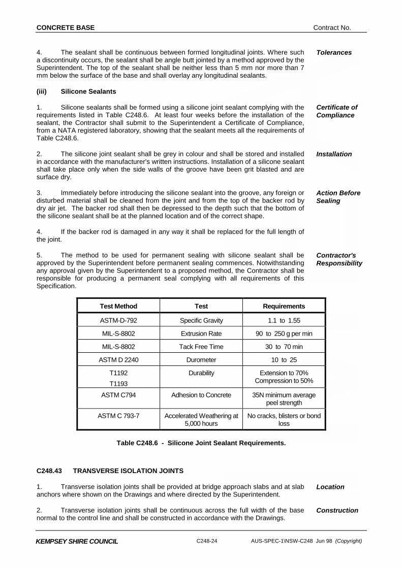
1. Silicone sealants shall be formed using a silicone joint sealant complying with the requirements listed in Table C248.6. At least four weeks before the installation of the sealant, the Contractor shall submit to the Superintendent a Certificate of Compliance, from a NATA registered laboratory, showing that the sealant meets all the requirements of Table C248.6.
Certificate of Compliance
2. The silicone joint sealant shall be grey in colour and shall be stored and installed in accordance with the manufacturer's written instructions. Installation of a silicone sealant shall take place only when the side walls of the groove have been grit blasted and are surface dry.
Installation
3. Immediately before introducing the silicone sealant into the groove, any foreign or disturbed material shall be cleaned from the joint and from the top of the backer rod by dry air jet. The backer rod shall then be depressed to the depth such that the bottom of the silicone sealant shall be at the planned location and of the correct shape.
Action Before Sealing
4. If the backer rod is damaged in any way it shall be replaced for the full length of the joint.
5. The method to be used for permanent sealing with silicone sealant shall be approved by the Superintendent before permanent sealing commences. Notwithstanding any approval given by the Superintendent to a proposed method, the Contractor shall be responsible for producing a permanent seal complying with all requirements of this Specification.
Contractor's Responsibility
Test Method Test Requirements
ASTM-D-792 Specific Gravity 1.1 to 1.55
MIL-S-8802 Extrusion Rate 90 to 250 g per min
MIL-S-8802 Tack Free Time 30 to 70 min
ASTM D 2240 Durometer 10 to 25
T1192 T1193
Durability Extension to 70% Compression to 50%
ASTM C794 Adhesion to Concrete 35N minimum average peel strength
ASTM C 793-7 Accelerated Weathering at 5,000 hours
No cracks, blisters or bond loss
Table C248.6 - Silicone Joint Sealant Requirements.
C248.43 TRANSVERSE ISOLATION JOINTS
1. Transverse isolation joints shall be provided at bridge approach slabs and at slab anchors where shown on the Drawings and where directed by the Superintendent.
Location
2. Transverse isolation joints shall be continuous across the full width of the base normal to the control line and shall be constructed in accordance with the Drawings.
Construction
Contract No. CONCRETE BASE
AUS-SPEC-1\NSW-C248 Jun 98 (Copyright) C248-25
KEMPSEY SHIRE COUNCIL
3. Transverse isolation joints shall not be placed closer than 2.0 m to other transverse joints. Where necessary, the Superintendent shall authorise a change in the spacing and/or skew of adjacent transverse contraction joints to ensure that sufficient clearance is obtained.
Spacing
4. Joint filler shall consist of preformed jointing material of bituminous fibreboard and the joint sealant shall comply with the silicone sealant requirements of Clause C248.42. They shall be installed in accordance with the Drawings and in a manner conforming to the manufacturers recommendations except that reference to backer rods shall not apply.
Standards
5. The line of the isolation joint shall not deviate from a 3m straightedge more than 10mm.
Tolerance
C248.44 LONGITUDINAL TIED JOINTS
(a) General
1. Longitudinal tied joints shall be provided at the locations shown on the Drawings or where directed by the Superintendent. The joints shall be parallel to the control line and/or to the dimensions and details shown on the Drawings.
Location
2. Longitudinal tied joints shall be formed or induced either by sawing or by machine insertion of a crack inducer ribbon.
Formation
3. The ties shall be 12mm diameter deformed steel bars Grade 400Y, 1m long and shall be inserted in accordance with Clause C248.18. Tie bars shall be located and spaced as shown on the Drawings. All parts of any tie bar shall lie within 50mm of its designed position. Tie bars shall be omitted within 500mm of a transverse joint. The epoxy to be used when installing tie bars in existing concrete shall be hydrophilic epoxy resin. The setting system used shall develop an anchorage strength at least 85 per cent of the yield strength of the bar.
Ties
4. The line of longitudinal tied joints shall not deviate from the designed position at any point by more than 10mm. The line shall also not deviate from a 3m straightedge by more than 10mm having made due allowance for any planned curvature.
Tolerances
5. Where the longitudinal tied joint is formed or slipformed, the joint face shall be corrugated in accordance with the details shown on the Drawings.
Corrugated Joint Face
6. Where the multi-lane width is greater than 18m, a longitudinal isolation joint shall be constructed at each location shown on the Drawings and in accordance with Clause C248.46.
Isolation Joint
(b) Sawn-Induced Joints
1. Sawn longitudinal tied joints shall be provided to the dimensions shown on the Drawings. Sawcutting shall comply with Clause C248.42(b).
Location
2. Within twenty-four hours of sawing, the longitudinal tied joint shall be thoroughly cleaned of all debris and a neoprene backing rod, shall be inserted in accordance with the details shown on the Drawings.
Sealant Quality
3. The sealant shall be coated with a lubricant-adhesive compound approved by the Superintendent. The compound shall have a colour compatible with the pavement colour. The sealant shall be inserted into the groove by means of suitable equipment which shall not damage the sealant during insertion. The maximum increase in length of the sealant after installation shall be 10 per cent of the original length, otherwise the sealant shall be rejected.
Sealant Insertion
CONCRETE BASE Contract No.
C248-26 AUS-SPEC-1\NSW-C248 Jun 98 (Copyright)
KEMPSEY SHIRE COUNCIL
4. Joints in the sealant shall be kept to a minimum and shall be cemented together by an adhesive recommended by the Manufacturer. The top of the sealant shall be neither less than 5 mm nor more than 7 mm below the surface of the base, except where the sealant is depressed to lie under the transverse joint sealant.
Sealant Joints
(c) Ribbon-Induced Joints
1. Ribbon-induced longitudinal tied joints shall be provided to the dimensions and details shown on the Drawings. The inducer ribbon shall be machine-inserted so that the top of the ribbon does not protrude above the surface of the base, nor shall it lie below the surface of the base by more than 3 mm.
Location and Insertion
2. The inducer ribbon shall be a minimum of 0.5 mm thick. When placed, it shall be within 5o of the vertical plane. Inducer ribbon which curls on placement and when cut in the base is found to be curved in transverse section by more than 3 mm from straight shall be rejected.
Finish
3. At transverse construction joints, the inducer ribbon shall be carried through the joint sufficiently to allow a connection by strong stapling, or other method approved by the Superintendent, to the inducer ribbon to be used on the other side of the joint. When a join is necessary in the inducer ribbon during paving, the inducer ribbon on the new spool shall be similarly joined to the tail of the inducer ribbon on the old spool.
Join in Ribbon
(d) Treatment of Sawn Longitudinal Tied Joints Prior to Asphalt Overlay
1. Where asphalt surfacing over sawn longitudinal tied joints is specified, the sealant shall be depressed to a depth below the concrete surface of not less than 10 mm and, following thorough cleaning, the joint shall be sealed flush with the concrete surface with a bituminous rubber compound, approved by the Superintendent, compatible with the narrow groove.
Bituminous Rubber Compound
C248.45 LONGITUDINAL JOINT WITH KERB AND/OR GUTTER
1. Where kerbs and/or gutters are to be constructed within the shoulder of a concrete base, they shall be formed directly onto the concrete subbase and they may be cast either integrally with the concrete base or separately.
Form
2. Where constructed separately, they shall be tied to the concrete base by 12mm diameter deformed steel tie bars Grade 250S or 400Y, 1000mm long at 1m centres.
Tie Bars
3. The longitudinal joint shall be constructed parallel to the control line (parallel to the centre line for ramps) and to the dimensions shown on the Drawings. The tie bars shall be inserted in accordance with the Drawings and Clause C248.18.
Location
4. The face of the longitudinal joint need not be scabbled and the joint need not be sealed.
Face of Joint
5. The line of the longitudinal joint shall be constructed to the tolerances specified for longitudinal tied joints in accordance with Clause C248.44.
Tolerances
6. The construction of kerb and/or gutter shall be in accordance with the Specification for OPEN DRAINS INCLUDING KERB AND GUTTER – C224 regardless of method of construction except that the strength of the concrete used in the kerb and/or gutter shall be 36 MPa.
Specification
Contract No. CONCRETE BASE
AUS-SPEC-1\NSW-C248 Jun 98 (Copyright) C248-27
KEMPSEY SHIRE COUNCIL
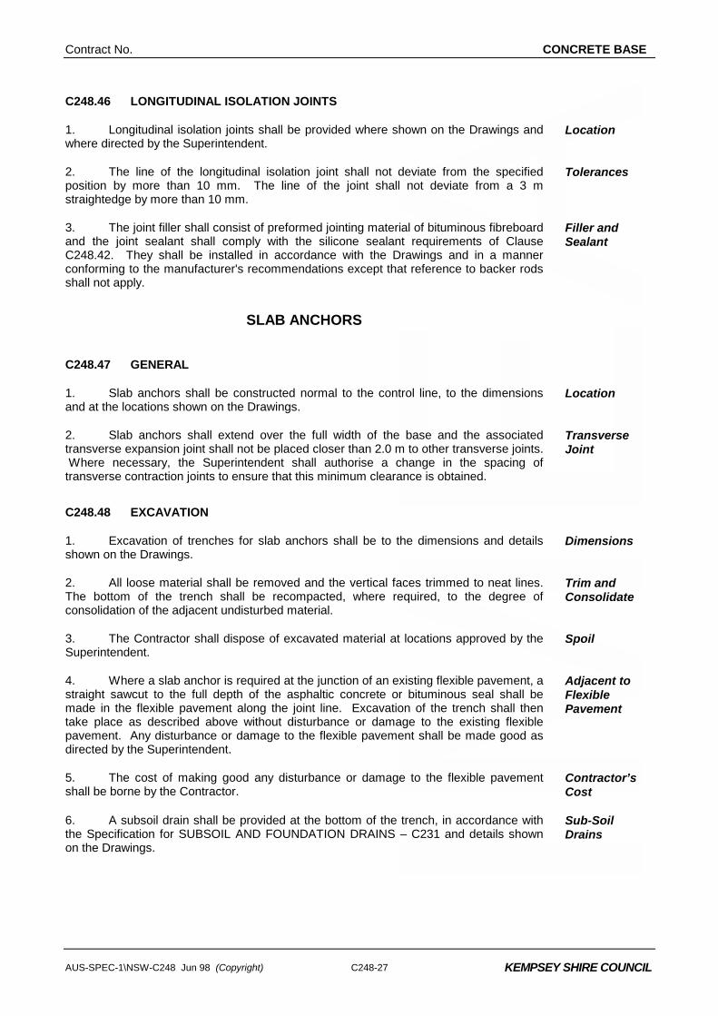
C248.46 LONGITUDINAL ISOLATION JOINTS
1. Longitudinal isolation joints shall be provided where shown on the Drawings and where directed by the Superintendent.
Location
2. The line of the longitudinal isolation joint shall not deviate from the specified position by more than 10 mm. The line of the joint shall not deviate from a 3 m straightedge by more than 10 mm.
Tolerances
3. The joint filler shall consist of preformed jointing material of bituminous fibreboard and the joint sealant shall comply with the silicone sealant requirements of Clause C248.42. They shall be installed in accordance with the Drawings and in a manner conforming to the manufacturer's recommendations except that reference to backer rods shall not apply.
Filler and Sealant
SLAB ANCHORS
C248.47 GENERAL
1. Slab anchors shall be constructed normal to the control line, to the dimensions and at the locations shown on the Drawings.
Location
2. Slab anchors shall extend over the full width of the base and the associated transverse expansion joint shall not be placed closer than 2.0 m to other transverse joints. Where necessary, the Superintendent shall authorise a change in the spacing of transverse contraction joints to ensure that this minimum clearance is obtained.
Transverse Joint
C248.48 EXCAVATION
1. Excavation of trenches for slab anchors shall be to the dimensions and details shown on the Drawings.
Dimensions
2. All loose material shall be removed and the vertical faces trimmed to neat lines. The bottom of the trench shall be recompacted, where required, to the degree of consolidation of the adjacent undisturbed material.
Trim and Consolidate
3. The Contractor shall dispose of excavated material at locations approved by the Superintendent.
Spoil
4. Where a slab anchor is required at the junction of an existing flexible pavement, a straight sawcut to the full depth of the asphaltic concrete or bituminous seal shall be made in the flexible pavement along the joint line. Excavation of the trench shall then take place as described above without disturbance or damage to the existing flexible pavement. Any disturbance or damage to the flexible pavement shall be made good as directed by the Superintendent.
Adjacent to Flexible Pavement
5. The cost of making good any disturbance or damage to the flexible pavement shall be borne by the Contractor.
Contractor’s Cost
6. A subsoil drain shall be provided at the bottom of the trench, in accordance with the Specification for SUBSOIL AND FOUNDATION DRAINS – C231 and details shown on the Drawings.
Sub-Soil Drains
CONCRETE BASE Contract No.
C248-28 AUS-SPEC-1\NSW-C248 Jun 98 (Copyright)
KEMPSEY SHIRE COUNCIL
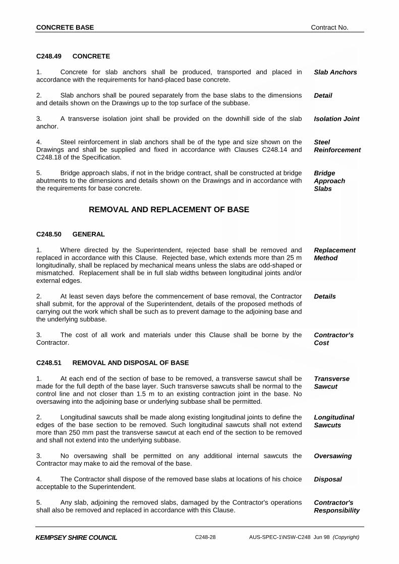
C248.49 CONCRETE
1. Concrete for slab anchors shall be produced, transported and placed in accordance with the requirements for hand-placed base concrete.
Slab Anchors
2. Slab anchors shall be poured separately from the base slabs to the dimensions and details shown on the Drawings up to the top surface of the subbase.
Detail
3. A transverse isolation joint shall be provided on the downhill side of the slab anchor.
Isolation Joint
4. Steel reinforcement in slab anchors shall be of the type and size shown on the Drawings and shall be supplied and fixed in accordance with Clauses C248.14 and C248.18 of the Specification.
Steel Reinforcement
5. Bridge approach slabs, if not in the bridge contract, shall be constructed at bridge abutments to the dimensions and details shown on the Drawings and in accordance with the requirements for base concrete.
Bridge Approach Slabs
REMOVAL AND REPLACEMENT OF BASE
C248.50 GENERAL
1. Where directed by the Superintendent, rejected base shall be removed and replaced in accordance with this Clause. Rejected base, which extends more than 25 m longitudinally, shall be replaced by mechanical means unless the slabs are odd-shaped or mismatched. Replacement shall be in full slab widths between longitudinal joints and/or external edges.
Replacement Method
2. At least seven days before the commencement of base removal, the Contractor shall submit, for the approval of the Superintendent, details of the proposed methods of carrying out the work which shall be such as to prevent damage to the adjoining base and the underlying subbase.
Details
3. The cost of all work and materials under this Clause shall be borne by the Contractor.
Contractor’s Cost
C248.51 REMOVAL AND DISPOSAL OF BASE
1. At each end of the section of base to be removed, a transverse sawcut shall be made for the full depth of the base layer. Such transverse sawcuts shall be normal to the control line and not closer than 1.5 m to an existing contraction joint in the base. No oversawing into the adjoining base or underlying subbase shall be permitted.
Transverse Sawcut
2. Longitudinal sawcuts shall be made along existing longitudinal joints to define the edges of the base section to be removed. Such longitudinal sawcuts shall not extend more than 250 mm past the transverse sawcut at each end of the section to be removed and shall not extend into the underlying subbase.
Longitudinal Sawcuts
3. No oversawing shall be permitted on any additional internal sawcuts the Contractor may make to aid the removal of the base.
Oversawing
4. The Contractor shall dispose of the removed base slabs at locations of his choice acceptable to the Superintendent.
Disposal
5. Any slab, adjoining the removed slabs, damaged by the Contractor's operations shall also be removed and replaced in accordance with this Clause.
Contractor's Responsibility

Contract No. CONCRETE BASE
AUS-SPEC-1\NSW-C248 Jun 98 (Copyright) C248-29
KEMPSEY SHIRE COUNCIL
C248.52 REPLACEMENT OF BASE
1. Before construction of the replacement base, the subbase shall be prepared and debonded in accordance with the Specification for MASS CONCRETE SUBBASE.
Subbase Preparation
2. All work involved in the replacement of base shall comply with the Specification, including the following additional requirements:-
Additional Requirements
(a) The joint faces on the adjoining slab at the transverse sawcuts shall be
deeply scabbled below the top 25 mm which shall be left smooth. Tie bars shall be provided to form a transverse construction joint in accordance with Clause C248.41.
(b) Transverse contraction joints shall be continuous across the full width of the base containing the replaced section. The length of the joint across the full width of the base shall be sealed with the same sealant as in adjacent work and in accordance with Clause C248.42.
(c) The lower two-thirds of the depth of the longitudinal joint faces shall be deeply scabbled and any concrete considered to be unsound by the Superintendent shall be removed. A crack inducer ribbon shall be attached to the surface of any formed longitudinal joint in the replacement base and tie bars provided to form a longitudinal tied joint in accordance with Clause C248.44.
(d) Tie bars placed into hardened concrete shall be set by the use of a hydrophilic epoxy resin. The setting system used shall develop an anchorage strength at least 85 per cent of the yield strength of the bar.
(e) Neither traffic nor construction equipment other than that associated with testing, sawcutting, groove cleaning or joint sealing shall be allowed on the section of base containing the replacement base until the joints have been permanently sealed and at least ten days have elapsed since placing replacement base concrete or the concrete has reached a compressive strength of at least 20MPa.
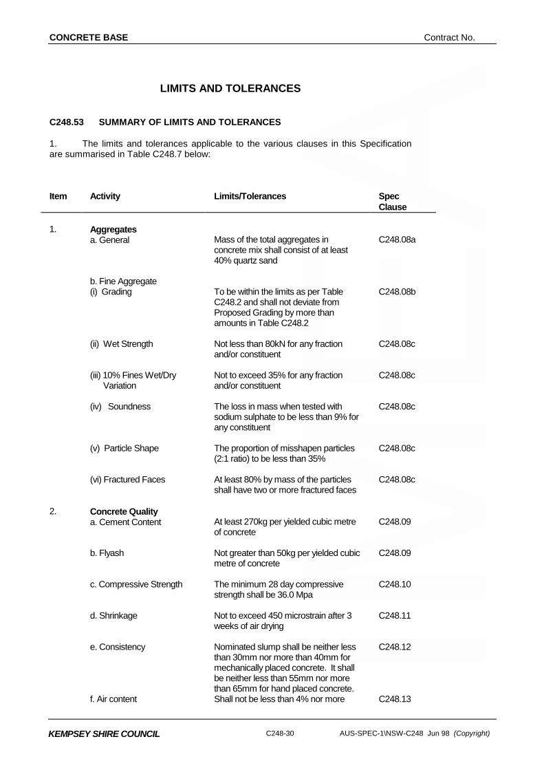
CONCRETE BASE Contract No.
C248-30 AUS-SPEC-1\NSW-C248 Jun 98 (Copyright)
KEMPSEY SHIRE COUNCIL
LIMITS AND TOLERANCES
C248.53 SUMMARY OF LIMITS AND TOLERANCES
1. The limits and tolerances applicable to the various clauses in this Specification are summarised in Table C248.7 below:
Item Activity Limits/Tolerances Spec
Clause 1. Aggregates
a. General Mass of the total aggregates in concrete mix shall consist of at least 40% quartz sand
C248.08a
b. Fine Aggregate
(i) Grading To be within the limits as per Table C248.2 and shall not deviate from Proposed Grading by more than amounts in Table C248.2
C248.08b
(ii) Wet Strength Not less than 80kN for any fraction
and/or constituent C248.08c
(iii) 10% Fines Wet/Dry
Variation Not to exceed 35% for any fraction and/or constituent
C248.08c
(iv) Soundness The loss in mass when tested with
sodium sulphate to be less than 9% for any constituent
C248.08c
(v) Particle Shape The proportion of misshapen particles
(2:1 ratio) to be less than 35% C248.08c
(vi) Fractured Faces At least 80% by mass of the particles
shall have two or more fractured faces C248.08c
2. Concrete Quality
a. Cement Content At least 270kg per yielded cubic metre of concrete
C248.09
b. Flyash Not greater than 50kg per yielded cubic
metre of concrete C248.09
c. Compressive Strength The minimum 28 day compressive
strength shall be 36.0 Mpa C248.10
d. Shrinkage Not to exceed 450 microstrain after 3
weeks of air drying C248.11
e. Consistency Nominated slump shall be neither less
than 30mm nor more than 40mm for mechanically placed concrete. It shall be neither less than 55mm nor more than 65mm for hand placed concrete.
C248.12
f. Air content Shall not be less than 4% nor more C248.13
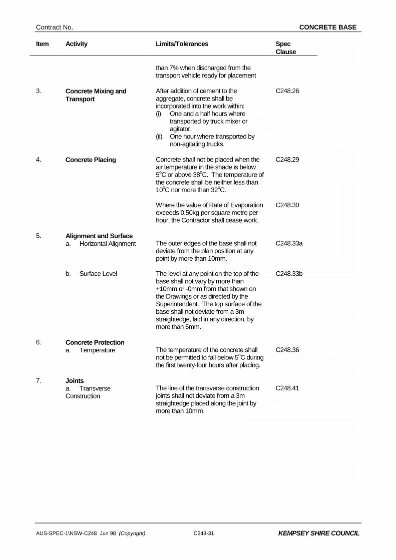
Contract No. CONCRETE BASE
AUS-SPEC-1\NSW-C248 Jun 98 (Copyright) C248-31
KEMPSEY SHIRE COUNCIL
Item Activity Limits/Tolerances Spec Clause
than 7% when discharged from the transport vehicle ready for placement
3. Concrete Mixing and
Transport After addition of cement to the aggregate, concrete shall be incorporated into the work within: (i) One and a half hours where
transported by truck mixer or agitator.
(ii) One hour where transported by non-agitating trucks.
C248.26
4. Concrete Placing Concrete shall not be placed when the
air temperature in the shade is below 5oC or above 38oC. The temperature of the concrete shall be neither less than 10oC nor more than 32oC.
C248.29
Where the value of Rate of Evaporation
exceeds 0.50kg per square metre per hour, the Contractor shall cease work.
C248.30
5. Alignment and Surface
a. Horizontal Alignment The outer edges of the base shall not deviate from the plan position at any point by more than 10mm.
C248.33a
b. Surface Level The level at any point on the top of the
base shall not vary by more than +10mm or -0mm from that shown on the Drawings or as directed by the Superintendent. The top surface of the base shall not deviate from a 3m straightedge, laid in any direction, by more than 5mm.
C248.33b
6. Concrete Protection
a. Temperature The temperature of the concrete shall not be permitted to fall below 5oC during the first twenty-four hours after placing.
C248.36
7. Joints
a. Transverse Construction
The line of the transverse construction joints shall not deviate from a 3m straightedge placed along the joint by more than 10mm.
C248.41
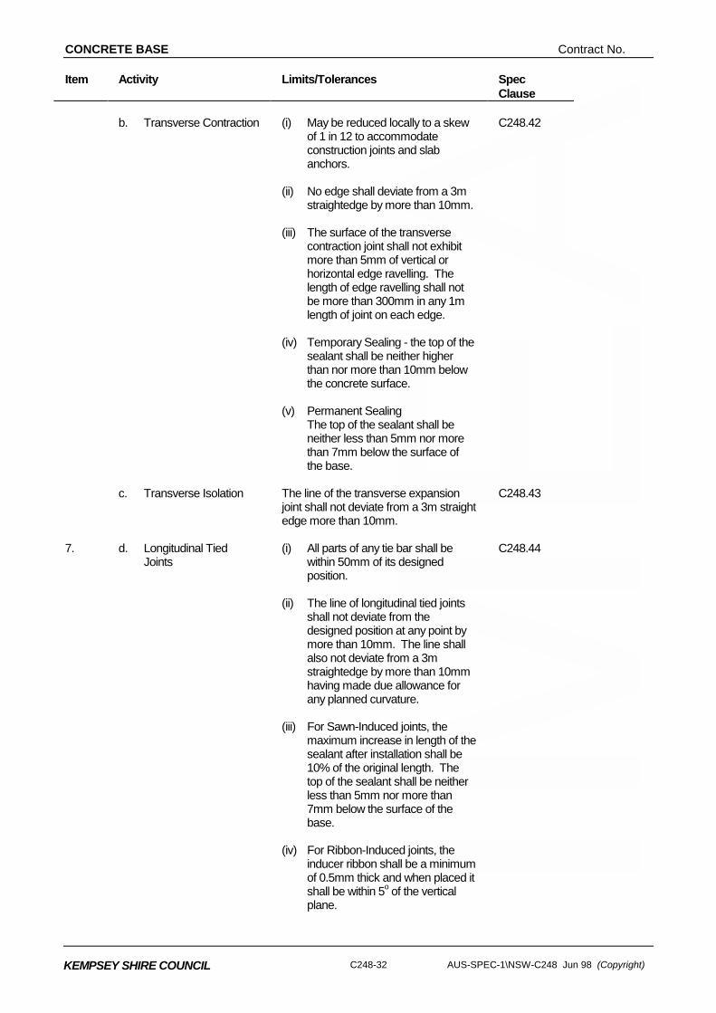
CONCRETE BASE Contract No.
C248-32 AUS-SPEC-1\NSW-C248 Jun 98 (Copyright)
KEMPSEY SHIRE COUNCIL
Item Activity Limits/Tolerances Spec Clause
b. Transverse Contraction (i) May be reduced locally to a skew
of 1 in 12 to accommodate construction joints and slab anchors.
(ii) No edge shall deviate from a 3m
straightedge by more than 10mm. (iii) The surface of the transverse
contraction joint shall not exhibit more than 5mm of vertical or horizontal edge ravelling. The length of edge ravelling shall not be more than 300mm in any 1m length of joint on each edge.
(iv) Temporary Sealing - the top of the
sealant shall be neither higher than nor more than 10mm below the concrete surface.
(v) Permanent Sealing The top of the sealant shall be
neither less than 5mm nor more than 7mm below the surface of the base.
C248.42
c. Transverse Isolation The line of the transverse expansion
joint shall not deviate from a 3m straight edge more than 10mm.
C248.43
7. d. Longitudinal Tied
Joints (i) All parts of any tie bar shall be
within 50mm of its designed position.
(ii) The line of longitudinal tied joints
shall not deviate from the designed position at any point by more than 10mm. The line shall also not deviate from a 3m straightedge by more than 10mm having made due allowance for any planned curvature.
(iii) For Sawn-Induced joints, the
maximum increase in length of the sealant after installation shall be 10% of the original length. The top of the sealant shall be neither less than 5mm nor more than 7mm below the surface of the base.
(iv) For Ribbon-Induced joints, the
inducer ribbon shall be a minimum of 0.5mm thick and when placed it shall be within 5o of the vertical plane.
C248.44
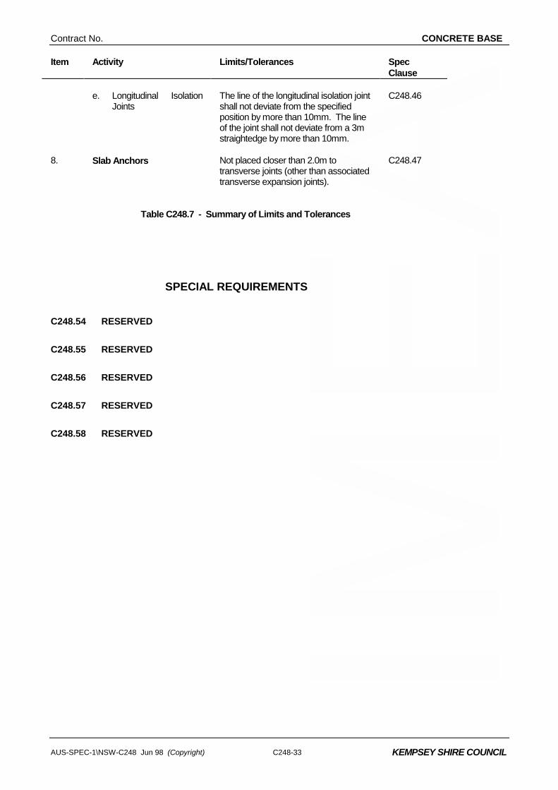
Contract No. CONCRETE BASE
AUS-SPEC-1\NSW-C248 Jun 98 (Copyright) C248-33
KEMPSEY SHIRE COUNCIL
Item Activity Limits/Tolerances Spec Clause
e. Longitudinal Isolation
Joints The line of the longitudinal isolation joint shall not deviate from the specified position by more than 10mm. The line of the joint shall not deviate from a 3m straightedge by more than 10mm.
C248.46
8. Slab Anchors Not placed closer than 2.0m to
transverse joints (other than associated transverse expansion joints).
C248.47
Table C248.7 - Summary of Limits and Tolerances
SPECIAL REQUIREMENTS
C248.54 RESERVED
C248.55 RESERVED
C248.56 RESERVED
C248.57 RESERVED
C248.58 RESERVED
CONCRETE BASE Contract No.
C248-34 AUS-SPEC-1\NSW-C248 Jun 98 (Copyright)
KEMPSEY SHIRE COUNCIL
MEASUREMENT AND PAYMENT
C248.59 RESERVED
Contract No. CONCRETE BASE
AUS-SPEC-1\NSW-C248 Jun 98 (Copyright)
KEMPSEY SHIRE COUNCIL
SPECIFICATION C248 PLAIN CONCRETE BASE
CLAUSE CONTENTS PAGE
GENERAL ............................................................................................................................ 1
C248.01 SCOPE ............................................................................................................................................. 1
C248.02 THICKNESS AND LEVELS OF BASE ............................................................................................. 1
C248.03 REFERENCE DOCUMENTS ........................................................................................................... 1
MATERIALS FOR CONCRETE............................................................................................ 2
C248.04 CEMENT .......................................................................................................................................... 2
C248.05 FLYASH............................................................................................................................................ 3
C248.06 WATER ............................................................................................................................................ 3
C248.07 ADMIXTURES .................................................................................................................................. 3
C248.08 AGGREGATES ................................................................................................................................ 4
QUALITY REQUIREMENTS OF CONCRETE ..................................................................... 6
C248.09 CEMENT AND FLYASH CONTENT ................................................................................................ 6
C248.10 COMPRESSIVE STRENGTH .......................................................................................................... 6
C248.11 SHRINKAGE..................................................................................................................................... 7
C248.12 CONSISTENCY................................................................................................................................ 7
C248.13 AIR CONTENT ................................................................................................................................. 7
STEEL REINFORCEMENT .................................................................................................. 7
C248.14 MATERIAL........................................................................................................................................ 7
C248.15 BENDING ......................................................................................................................................... 8
C248.16 SPLICING......................................................................................................................................... 8
C248.17 STORAGE ........................................................................................................................................ 8
C248.18 PLACING.......................................................................................................................................... 8
DESIGN AND CONTROL OF CONCRETE MIXES.............................................................. 9
CONCRETE BASE Contract No.
AUS-SPEC-1\NSW-C248 Jun 98 (Copyright))
KEMPSEY SHIRE COUNCIL
C248.19 GENERAL......................................................................................................................................... 9
C248.20 VARIATIONS TO APPROVED MIXES............................................................................................. 9
CONFORMANCE OF CONCRETE STRENGTH, COMPACTION AND THICKNESS ....... 10
C248.21 CONCRETE CYLINDERS.............................................................................................................. 10
C248.22 COMPRESSIVE STRENGTH OF CONCRETE ............................................................................. 11
C248.23 CONFORMANCE FOR THICKNESS............................................................................................. 12
C248.24 RELATIVE COMPACTION OF CONCRETE ................................................................................. 12
PRODUCTION, TRANSPORT AND CONSISTENCY OF CONCRETE ............................. 14
C248.25 PRODUCTION AND HANDLING OF CONCRETE........................................................................ 14
C248.26 MIXING AND TRANSPORT........................................................................................................... 14
C248.27 MIXING TIME ................................................................................................................................. 15
C248.28 CONSISTENCY.............................................................................................................................. 15
PLACING AND FINISHING CONCRETE BASE ................................................................ 15
C248.29 GENERAL....................................................................................................................................... 15
C248.30 RATE OF EVAPORATION............................................................................................................. 16
C248.31 MECHANICAL PAVING.................................................................................................................. 18
C248.32 HAND PLACING............................................................................................................................. 18
C248.33 ALIGNMENT AND SURFACE TOLERANCES .............................................................................. 19
C248.34 TEXTURING OF SURFACE .......................................................................................................... 19
C248.35 CURING ......................................................................................................................................... 19
C248.36 PROTECTION OF WORK ............................................................................................................. 20
C248.37 ODD-SHAPED AND MISMATCHED SLABS ................................................................................. 20
C248.38 TERMINAL SLABS......................................................................................................................... 21
C248.39 TRIAL CONCRETE BASE.............................................................................................................. 21
JOINTS............................................................................................................................... 21
C248.40 GENERAL....................................................................................................................................... 21
C248.41 TRANSVERSE CONSTRUCTION JOINTS ................................................................................... 22
Contract No. CONCRETE BASE
AUS-SPEC-1\NSW-C248 Jun 98 (Copyright)
KEMPSEY SHIRE COUNCIL
C248.42 TRANSVERSE CONTRACTION JOINTS...................................................................................... 22
C248.43 TRANSVERSE ISOLATION JOINTS ............................................................................................. 24
C248.44 LONGITUDINAL TIED JOINTS...................................................................................................... 25
C248.45 LONGITUDINAL JOINT WITH KERB AND/OR GUTTER ............................................................. 26
C248.46 LONGITUDINAL ISOLATION JOINTS........................................................................................... 27
SLAB ANCHORS ............................................................................................................... 27
C248.47 GENERAL....................................................................................................................................... 27
C248.48 EXCAVATION ................................................................................................................................ 27
C248.49 CONCRETE ................................................................................................................................... 28
REMOVAL AND REPLACEMENT OF BASE..................................................................... 28
C248.50 GENERAL....................................................................................................................................... 28
C248.51 REMOVAL AND DISPOSAL OF BASE.......................................................................................... 28
C248.52 REPLACEMENT OF BASE ............................................................................................................ 29
LIMITS AND TOLERANCES.............................................................................................. 30
C248.53 SUMMARY OF LIMITS AND TOLERANCES................................................................................. 30
SPECIAL REQUIREMENTS............................................................................................... 33
C248.54 RESERVED.................................................................................................................................... 33
C248.55 RESERVED.................................................................................................................................... 33
C248.56 RESERVED.................................................................................................................................... 33
C248.57 RESERVED.................................................................................................................................... 33
C248.58 RESERVED.................................................................................................................................... 33
MEASUREMENT AND PAYMENT..................................................................................... 34
C248.59 RESERVED.................................................................................................................................... 34