Embed Size (px)
Citation preview
Developing a Hardware Evaluation Methodfor SHA-3 Candidates
Luca Henzen, Pietro Gendotti, Patrice Guillet, Enrico Pargaetzi,Martin Zoller, and Frank K. Gurkaynak
CHES 2010

Overview
1. Introduction
2. Hardware evaluation methodology
3. Implementation
4. Results
5. Conclusions
2 / 20

SHA-3 competition
NIST started public competition to select new standard SHA-3
Motivations• Digital fingerprint out of an arbitrary-length file• Security weaknesses found in MD5 and SHA-1• Security concern with SHA-2
First Round
Final Round
SHA-3 Winner
2008 2009NIST SHA-3 Schedule 2010
Second Round
2011 2012
Final Conference
Second Conference
First Conference
51
14
5
1
3 / 20

SHA-3 performance evaluation
Security• Cryptographic strength is essential
Efficiency• Software: Several implementations in different general-purpose
architectures and performance extensively investigated (eBASH)• Hardware: Hardware performance comparison impractical due
to different implementation technologies and lack of constrains
Flexibility• Utilized in both high-performance and resource constrained
environments• Good performance in terms of speed, area and power
4 / 20

SHA-3 involvement
Development of BLAKE
VLSI Implementation• VLSI characterization of several second round candidates within
student projects• Designs manufactured in three different ASICs• 12 out of 14 candidate algorithms implemented (all apart from
ECHO and SIMD)
Development of a methodology to evaluate ASIC implementationof all SHA-3 second round candidates
• Optimize all algorithms for multiple clearly defined specifications• Apply methodology and evaluate several architectural variations• Openness of results
5 / 20

Evaluation methodology
Lack of concrete hardware specifications• Hardware specifications determined by the application• Trade-offs between silicon area, energy consumption and
throughput
Which parameters are more important?• Very wide range of application with different requirements• Focus on one parameter (throughput)• Aggregate performance metrics (throughput per mm2)
6 / 20
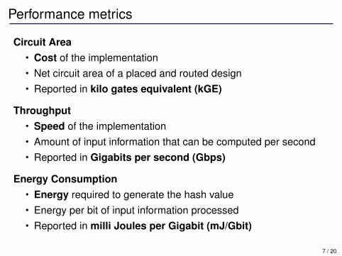
Performance metrics
Circuit Area• Cost of the implementation• Net circuit area of a placed and routed design• Reported in kilo gates equivalent (kGE)
Throughput• Speed of the implementation• Amount of input information that can be computed per second• Reported in Gigabits per second (Gbps)
Energy Consumption• Energy required to generate the hash value• Energy per bit of input information processed• Reported in milli Joules per Gigabit (mJ/Gbit)
7 / 20

Selection of algorithm parameters
NIST SHA-3 Minimum Requirements• Message digest size of 224, 256, 384, 512-bits• Maximum message length of 264 − 1 bits
Our Requirements:Message digest size
• Slightly different architectures for different output length• 256-bits version for smaller hardware and faster implementation
Message block size• Largest message block size available• Message already padded• Very long message for throughput calculation
8 / 20

Definition of algorithm specifications (I)
NIST Specifications• Computationally efficient• Limited memory requirements• Flexible• Simple
Separate Specifications• High-Throughput and Moderate-Throughput targets• Fairer comparison between remaining performance metrics• Possible to highlight flexibility
9 / 20

Definition of algorithm specifications (II)
90 nm CMOS process technology by UMC
High-Throughput: 20 Gbps• Beyond expected performance• Rank algorithms on maximum throughput capability and circuit
area occupation
Moderate-Throughput: 0.2 Gbps• Easily achievable• Rank algorithms focusing on energy consumption and circuit
area occupation
10 / 20

ASIC realizations
Several practical factors haveaffected results
• Maximum available siliconarea
• Total number of I/O pins• Test infrastructure limited
capabilities• Test structures overhead
(scan chains)• Shared common interface• Clock frequency domains• Scheduling constrains
11 / 20
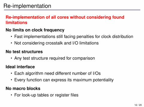
Re-implementation
Re-implementation of all cores without considering foundlimitations
No limits on clock frequency• Fast implementations still facing penalties for clock distribution• Not considering crosstalk and I/O limitations
No test structures• Any test structure required for comparison
Ideal interface• Each algorithm need different number of I/Os• Every function can express its maximum potentiality
No macro blocks• For look-up tables or register files
12 / 20

Design flow
Front-End Design• Same design procedure for all candidate algorithms• Worst case condition characterization of standard cell libraries
Worst Case Typical Case Best Case
Supply Voltage 1.08 V 1.2 V 1.32 VTemperature 125 °C 27 °C -40 °CCritical Path 3.49 ns 2.24 ns 1.59 nsThroughput 13.75 Gbps 21.42 Gbps 30.19 GbpsRelative Performance 64.2 % 100 % 140.9 %
Back-End Design• Square floorplan• Set 85% of core area utilization• Statistical power analysis to determine energy consumption
13 / 20

Algorithm optimization
Several architectural transformations• Parallelization, pipelining, loop-unrolling
Different computational method to perform a specifictransformation
• Substitution boxes as look-up tables or as a mathematicalfunction
Identify the best design not a trivial task• Large set of circuit with different trade-offs between speed and
size• Selected the most appropriate architecture with minimal resource
Open source codes and run scripts for EDA tools
14 / 20

Results
Figures of Merit• Circuit Area• Energy Consumption• Maximum Clock Frequency• Maximum Achievable Throughput• Target Throughput Clock Frequency• Maximum/Target Clock Frequency Ratio
Representation of the performance for high and moderate speedenvironments
• Comparison to overview efficiency and flexibility• Refrain from concluding remarks
15 / 20

High-Throughput scenario 20 Gbps
• Only two algorithms able to reach throughput target• Both area and energy sacrificed to achieve high-throughput• Local congestion for 8-bit LUT-based S-boxes (ECHO, Grøstl,
Fugue, SHAvite)
16 / 20

Moderate-Throughput scenario 0.2 Gbps
• All circuits match target throughput easily• Area and energy dissipation main figure of merit• No special precaution for low-power design
17 / 20

Sources of error
Conflict of interest• A co-author is involved with one candidate
Designer experience• Different designers may be more successful than others
Accuracy of numbers• Accuracy of synthesis and analysis tools: ±5%
Bias trough specification• Design corners favor some algorithms• New studies with different specifications
Simplification due to assumptions• Design flow assumptions necessary to develop the methodology
18 / 20

Conclusions
Presented a methodology to compare SHA-3 candidatealgorithms
• Set limits for one performance metric (throughput)• Re-implemented all algorithms to meet two distinct throughput
requirements to compare flexibility
Difficult to present an authoritative and fair evaluation of allsecond round candidates
A similar approach utilized for final round evaluation• Set clear constrains• Target more than one performance metrics• Evaluation process well documented and material available• Addition of low-power corner
19 / 20

Thank you
http://www.iis.ee.ethz.ch/∼sha3
20 / 20

Measured Results
Algorithm Area Throughput Energy Technology[kGE] [Gbps] [mJ/Gbit] [nm]
BLAKE-32 33.55 7.314 15.291 UMC 90BMW-256 95.00 3.527 31.407 UMC 180CubeHash16/32-256 39.69 8.000 20.700 UMC 90Fugue-256 26.00 2.806 122.506 UMC 180Grøstl-256 65.00 4.064 73.075 UMC 180Hamsi-256 32.25 7.467 23.624 UMC 90Hamsi-512 68.66 7.467 46.605 UMC 90JH-256 44.00 2.371 72.885 UMC 180Keccak-256† 27.85 39.822 5.726 UMC 90Keccak-512† 26.94 19.911 11.933 UMC 90Luffa-256 29.70 22.400 9.482 UMC 90Shabal-256 35.99 4.923 30.713 UMC 90SHAvite-3256 48.00 2.452 93.764 UMC 180Skein-256-256 27.00 1.917 44.329 UMC 180
† First round specification.
20 / 20
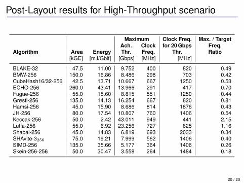
Post-Layout results for High-Throughput scenario
Maximum Clock Freq. Max. / TargetAch. Clock for 20 Gbps Freq.
Algorithm Area Energy Thr. Freq. Thr. Ratio[kGE] [mJ/Gbit] [Gbps] [MHz] [MHz]
BLAKE-32 47.5 11.00 9.752 400 820 0.49BMW-256 150.0 16.86 8.486 298 703 0.42CubeHash16/32-256 42.5 13.71 10.667 667 1250 0.53ECHO-256 260.0 43.41 13.966 291 417 0.70Fugue-256 55.0 15.60 8.815 551 1250 0.44Grøstl-256 135.0 14.13 16.254 667 820 0.81Hamsi-256 45.0 15.90 8.686 814 1876 0.43JH-256 80.0 17.54 10.807 760 1406 0.54Keccak-256 50.0 2.42 43.011 949 441 2.15Luffa-256 55.0 6.92 23.256 727 625 1.16Shabal-256 45.0 14.83 6.819 693 2033 0.34SHAvite-3256 75.0 19.21 7.999 562 1406 0.40SIMD-256 135.0 35.66 5.177 364 1406 0.26Skein-256-256 50.0 30.47 3.558 264 1484 0.18
20 / 20
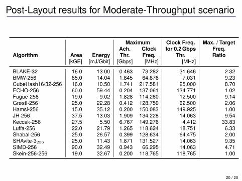
Post-Layout results for Moderate-Throughput scenario
Maximum Clock Freq. Max. / TargetAch. Clock for 0.2 Gbps Freq.
Algorithm Area Energy Thr. Freq. Thr. Ratio[kGE] [mJ/Gbit] [Gbps] [MHz] [MHz]
BLAKE-32 16.0 13.00 0.463 73.282 31.646 2.32BMW-256 85.0 14.04 1.845 64.876 7.031 9.23CubeHash16/32-256 16.0 10.50 1.741 217.581 25.000 8.70ECHO-256 60.0 59.44 0.204 137.061 134.771 1.02Fugue-256 19.0 9.02 1.828 114.260 12.500 9.14Grøstl-256 25.0 22.28 0.412 128.750 62.500 2.06Hamsi-256 15.0 35.12 0.200 150.083 149.925 1.00JH-256 37.5 13.03 1.909 134.228 14.063 9.54Keccak-256 27.5 5.50 6.767 149.276 4.412 33.83Luffa-256 22.0 21.79 1.265 118.624 18.751 6.33Shabal-256 25.0 26.57 0.399 128.634 64.475 2.00SHAvite-3256 25.0 11.43 1.871 131.527 14.063 9.35SIMD-256 90.0 32.49 0.943 66.295 14.063 4.71Skein-256-256 19.0 32.67 0.200 118.765 118.765 1.00
20 / 20

Design specifications of the architectures (I)
Alg. Block Arch. Lat. Implementation details[bits] [cycles]
BLAKE 512 HS 21 Four parallel G function modules, anticipation of the first message-constantaddition.
MS 81 One G function module.
BMW 512 HS-MS 18 (+18) f0 and f2 computed in one cycle, while f1 iteratively decomposed in asingle expand block.
CubeHash 256 HS 16 (+160) Single round per cycle, initial state stored.
MS 32 (+320) Half round, initial state stored.
ECHO 1536 HS 32 8 AES rounds per clock cycle.
MS 1034 Single 32-bit AES core, one parallel BigMixColumn unit.
Fugue 32 HS 2 (+37) S-box as LUT.
MS 2 (+37) S-box as composite field logic.
Grøstl 512 HS 21 (+21) Interleaved P and Q permutation with one pipeline stage, SubBytes as LUT.
MS 160 (+160) Single-column round (64-bit datapath), SubBytes as composite field.
Hamsi 32 HS 3 (+6) Message expansion in three 256×256 LUTs, single round per cycle, sub-stitution layer as logic.
MS 24 (+48) Same as HS, datapath reduced to 128 bits.
20 / 20

Design specifications of the architectures (II)
Alg. Block Arch. Lat. Implementation details[bits] [cycles]
JH 512 HS-MS 36 S-boxes S0 and S1 stored in LUTs, constants stored.
Keccak 1088 HS-MS 24 Single round per cycle.
Luffa 256 HS 8 Three parallel Step function modules, SubCrumb function as logic.
MS 24 One Step function modules, SubCrumb function as logic.
Shabal 512 HS 52 (+156) One keyed permutation round per cycle. In total, 30 adders and 16 subtrac-tors.
MS 165 One adder and one subtractor only.
SHAvite-3 512 HS 36 One AES round for message expansion and one AES round for the F3
round, SubBytes as LUT.
MS 36 Same as HS, SubBytes in composite field.
SIMD 512 HS-MS 36 (+36)†Four parallel Feistel modules, message expansion based on NNT8 andeight multipliers for tweadle mult.
Skein 256 HS 19 (+19) Four unrolled Threefish rounds.
MS 152 (+152) Half Threefish round.
† Further 36 cycles of initialization required for message expansion.
20 / 20