Embed Size (px)
Citation preview

TECHNICAL NOTE
1
DETERMINATION OF THE LONG TERM PROPERTIES FOR MIRAFI
® PET-SERIES
REINFORCEMENT GEOTEXTILES BY GRI-GT7 AND NCMA GUIDELINES
Prepared by: TenCate
TM Geosynthetics North America
365 South Holland Drive Pendergrass, GA 30567 Tel 706 693 2226 Fax 706 693 4400 www.tencate.com Revised: October 4, 2011

TECHNICAL NOTE
2
Mirafi® PET-Series geotextiles are the leading polyester geotextiles used for soil reinforcement applications. Starting in the late 1980s, extensive research and testing have been performed on PET geotextiles to determine the long term, in-situ properties.
This technical note describes each of the relevant properties in detail and the appropriate testing conducted on PET geotextiles. Additional documentation, along with the actual test reports, is available from TenCate Geosynthetics North America.
Product Description PET-Series geotextiles are high strength, high tenacity, woven polyester geotextiles manufactured in a full range of tensile strengths.
Mirafi® PET-Series geotextiles are used in a wide variety of soil reinforcement applications including reinforced embankment foundations, segmental retaining walls, steep reinforced slopes, and reinforcement in a variety of landfill applications including void bridging and veneer stability. Applications where long term design strength is necessary for the stability of the structure are ideal applications where PET-Series geotextiles can be used.
Standard roll dimensions for Mirafi® PET-Series geotextiles are as follows:
Product Standard Roll
Dimensions Width x Length m (ft)
Product Standard Roll Dimensions
Width x Length m (ft)
PET70/70 15 x 300 (4.5 x 91.5) PET400/50 16.4 x 656 (5 x 200)
PET100 15 x 300 (4.5 x 91.5) PET600/100 16.4 x 492 ( 5 x 150)
PET150 15 x 300 (4.5 x 91.5) PET800/100 16.4 x 328 ( 5 x100)
PET200 15 x 300 (4.5 x 91.5) PET1000/100 16.4 x 328 ( 5 x100)
PET300 15 x 300 (4.5 x 91.5)

TECHNICAL NOTE
3
Polymer type and grade Mirafi® PET-Series geotextiles contain no post-consumer recycled material. PET-Series geotextiles are produced from high molecular weight (Mn), low carboxyl end group (CEG), high tenacity polyester (PET) yarns. The reinforcement direction yarns have the following physical properties:
Minimum Average Molecular Weight > 25,000
Carboxyl End Groups < 30

TECHNICAL NOTE
4
Ultimate Strength, TULT (Minimum Average Roll Value) Determining the Ultimate Strength, TULT , is conducted per ASTM D4595, “Standard Test Method for Tensile Properties of Geotextiles by the Wide-Width Strip Method.” The frequency of testing exceeds the requirements in ASTM D4354, “Practice for Sampling of Geosynthetics for Testing”. The machine direction ultimate tensile strength values for PET-Series geotextiles are as follows:
Product MARV for TULT kN/m (lbs/ft)
Product MARV for TULT kN/m (lbs/ft)
PET70/70 70 (4,800) PET400/50 400 (27,412)
PET100 105.1 (7,200) PET600/100 600 (41,119)
PET150 140.1 (9,600) PET800/100 800 (54,826)
PET200 201.4 (13,800) PET1000/100 1000 (68,532)
PET300 300.4 (20,580)
Quality Control System PET-Series geotextile quality control testing is conducted in accordance with documented and controlled American Society for Testing and Materials (ASTM) or Geosynthetic Research Institute (GRI) test methods at TenCate’s A2LA and GRI-LAP approved laboratory. In the case of product properties where a method of inspection is not well established, methods are selected that have been published in national or international standards by reputable technical organizations or in relevant scientific texts or journals. The use of these selected methods are verified and approved by the Quality Assurance Manager.
The testing of PET-Series geotextiles is carried out under controlled conditions including the following:
Overall management of process control is governed by documented procedures.
Documented test methods and work instructions govern the comprehensive inspection and testing of each production lot.
Testing equipment is selected based upon needs and the ability to satisfy specified requirements with the equipment being suitably maintained.
Training of personnel is adequate and documented.
Appropriate Quality Records are maintained. Each sample to be tested is accompanied with a label indicating the unique manufacturing roll number. Test results are recorded on Quality Control Test Reports by number and then entered into a computer database by roll number. Once the sample has been delivered to the Quality Control lab, the sample is tested. The standard operating procedure for each test is documented with copies of the appropriate test procedure on file in the Quality Control laboratory.

TECHNICAL NOTE
5
The preparation for each sample is conducted in accordance with Standard Operating Procedures and ASTM requirements.
Figure 2: Wide Width Test on PET Geotextile.
The testing frequencies for PET-Series geotextiles comply with ASTM requirements and are as follows:
Physical Property Minimum Frequency
ASTM D5261 Mass per Unit Area 1 per lot
ASTM D5199 Thickness 1 per lot
ASTM D4595 Wide Width Tensile Strength 1 per lot
Creep Reduction Factor, RFCR All polymers used in the manufacture of geosynthetics are subject to sustained load deformation or creep [4]. Creep behavior is a function of stress level, time, temperature (environment), and molecular structure [4]. The reduction factor for creep, RFCR, is used to limit the magnitude of creep at specified strain levels over a specific time period.
There are three methods for measuring geosynthetic creep: Conventional Creep Testing, Time-temperature Superposition (TTS), and Stepped Isothermal Method (SIM)

TECHNICAL NOTE
6
[6]. Creep Reduction Factors for PET-Series geotextiles were determined by conventional creep testing performed by SGI.
Testing Services and SIM testing performed by TRI/Environmental.
The validation of the creep factors currently used for PET-Series geotextiles is based on over 300,000+ hours of conventional creep testing. As a result loads of at least 60% (RFCR = 1.67) of the ultimate tensile strength (per ASTM D4595) are reasonable for use in determining the creep reduction factor for PET-Series geotextiles. Durability Reduction Factor, RFD Geosynthetics, like all other construction materials, slowly degrade over time. The rate of degradation depends on the molecular make-up of the geosynthetic polymer and the nature of the environment to which the geosynthetic is exposed. Since most geosynthetics are buried in non-aggressive soil environments, geosynthetic degradation normally occurs at a very slow, almost un-measurable, rate. Still, it is possible for significant rates of degradation to take place if unstable polymers are used or extreme conditions are encountered as described in subsequent sections. The partial reduction factor for durability, RFD, is derived from testing. Figure 4 compiles the reduction factors associated with durability testing reported [7]. These reduction factors are compared with the more conservative FHWA/Industry guidelines [8, 10]. Mirafi® geosynthetics were included in several of the referenced tests.

TECHNICAL NOTE
7
Durability Reduction Factor, RFD
Figure 4. Durability Reduction Factors, RFD, for High Strength Geosynthetics @ 75 Years
“Default” partial reduction factors for durability, RFD, are recommended where polymer stability can be demonstrated and where the anticipated soil environment is non-aggressive. FHWA has given some conservative guidance on the selection of the RFD in the absence of product-specific testing [6][8]. Yet, specific product testing and field experience has demonstrated that the RFD value shown in the table below are commonly applicable to polyester geotextiles and coated geogrids as long as minimum molecular weight and maximum number Carboxyl End Groups are maintained.
Recommended RFD for Mirafi® PET-Series Geotextiles in Typical Soils:
Geosynthetic Type Minimum PET Yarn Criteria RFD
Woven Polyester (PET) Geotextiles Mn > 25,000; CEG < 30 1.1
The FHWA publication NHI-09-083 “Design and Construction of Mechanically Stabilized Earth Walls and Reinforced Soil Slopes,” recommends electrochemical properties for backfills when using geosynthetic reinforcement in a pH range of 3 < pH < 9. Based on

TECHNICAL NOTE
8
research outlined in “The Effect of pH, Resin Properties, and Manufacturing Process on Laboratory Degradation of Polyester Geosynthetics” by V. Elias, A. Salman, and D. Goulias [9], a RFD = 1.10 is reasonable for all PET-Series geotextiles in the recommended pH range. Soils exhibiting pH ranges beyond the 3 to 9 limits may be used in the construction of geosynthetically reinforced earth structures. However, adjustments to the reduction factor may be required. The geotextile product evaluated in this study is a high tenacity, woven polyester fabric manufactured from Type 250 yarn. This yarn type is equal to that used in manufacture of Mirafi® PET-Series geotextiles. Installation Damage Reduction Factor, RFID Placement of some types of fill on a geosynthetic in the field can result in installation damage to the material. This is typically reflected by a reduction of the tensile strength properties of the geosynthetic. Installation damage is determined by subjecting the geosynthetic to a backfill and compaction cycle, exhuming the material, and determining the strength retained [1]. Extensive research has been conducted on PET-Series geotextiles to determine the potential effects of construction damage. The most comprehensive testing has been conducted by TRI/Environmental. The method was developed by Watts and Brady of the Transport Research Laboratory (TRL) in the United Kingdom and documented as TRL’s “Procedure for Installation Damage Test for BBA Assessments” (CERC.SOIL.TM028, Jan. 1997). TRI used this procedure as modified to generally conform to ASTM D5818 requirements. [12] The strength reduction factors to account for installation damage to the reinforcement, RFID, for Mirafi® PET-Series geotextiles are shown in the following table:
Soil Type PET70/70 PET100 PET150 PET200 PET300
Type 3 (Sand, Silt, Clay) 1.15 1.15 1.15 1.15 1.10
Type 2 (Sandy Gravel) 1.25 1.25 1.25 1.25 1.20
Type 1 (Gravel) 1.50 1.50 1.50 1.50 1.40
Soil Type PET400/50 PET600/100 PET800/100 PET1000/100
Type 3 (Sand, Silt, Clay) 1.10 1.10 1.10 1.10
Type 2 (Sandy Gravel) 1.20 1.20 1.20 1.20
Type 1 (Gravel) 1.40 1.40 1.40 1.40
Interaction Coefficients for Pullout and Sliding Reinforcement applications using geosynthetics require an estimate of two interaction coefficients [1]. The Coefficient of Shear Stress Interaction (Ci) is required to calculate the reinforcement pullout capacity of the geosynthetic [1]. The Coefficient of Direct Sliding (Cds) is required to calculate the resistance to internal sliding generated along the surface of the geosynthetic [1].

TECHNICAL NOTE
9
The Coefficient of Shear Stress Interaction, Ci, and Coefficient of Direct Sliding, Cds, for PET-Series geotextiles were determined from independent testing [5] [11] and are as follows:
Soil Type U.S.C.S. Ci Cds
Silty clay, sandy clay, clayey silt (ML, CL) 0.7 – 0.8 0.7
Silty sands, fine to medium sands (SM, SP, SW) 0.8 – 0.9 0.8
Dense well-graded sand, sand and gravel (SW, GP, GW) 0.9 – 1.0 0.9
Extensive research has been conducted on the interaction properties of PET-Series geotextiles. A research paper entitled “Soil Interaction Characteristics of Geotextiles and Geogrids” by Koutsourais, Sandri, and Swan [11] and actual testing by SGI Testing Services [13] on PET-Series geotextiles in these fill types provide detailed evidence verifying the values listed above. UV Resistance Sunlight is an important cause of degradation to all organic materials, including polymers from which geosynthetics are produced [4]. Of the three types of energy produced from the sun, ultraviolet (UV) is the most harmful to geosynthetics. For laboratory simulation of sunlight, artificial light sources (lamps) are generally compared to worst-case conditions [4]. The recommended ASTM test for geosynthetics is D4355 which exposes samples to simulated UV conditions [4]. The minimum UV Resistance of PET-Series geotextiles is 50% strength retained after 250 hours of exposure. This determination has been made by ASTM D4355 testing conducted by TRI/Environmental and verified in our quality control laboratories.
DETERMINATION OF Long Term Design Strength (LTDS, Tallow) Mirafi® PET-Series geotextiles are used in a variety of long-term reinforcement applications. The determinations of the correct tensile strength and soil interaction properties are critical in the design phase of a project.
There are currently three accepted methods for determining the long-term reinforcement strength of a geosynthetic material. These methods are:
GRI-GT7: “Determination of the Long-Term Design Strengths of Geotextiles”
NCMA “Design Manual for Segmental Retaining Walls”, 2nd
Edition AASHTO Standard Specifications for Highway Bridges, 1997 Interim The three methodologies above differ in the nomenclature used to determine the allowable strength of the reinforcement. The nomenclature for this long term allowable strength is as follows:
GRI-GG4 uses “Tallow” NCMA uses “LTDS” AASHTO uses “Tal”

TECHNICAL NOTE
10
For this technical note, the Long-Term Design Strength calculation follows both the GRI and NCMA [1, 2] methodologies. In general, however, the reduction factor concept is applicable to all three methods and the long-term reinforcement strength. However, individual reduction factors may vary depending on the requirements of each specific method. The design engineer should review and verify the required limit equilibrium strength calculation method and appropriate reduction factors before design of the reinforced soil structure.
The Long-Term Design Strength (LTDS, Tallow) of a geosynthetic is the strength at limit equilibrium conditions in the soil [1, 2]. The limit equilibrium strength is developed by reducing the Ultimate Tensile Strength by Reduction Factors for potential material degradation.
The Long Term Design Strength or Allowable Tensile Strength is determined as follows:
Tallow
= LTDS = TULT
÷ (RFID
x RFCR
x RFD) Where:
TULT is the minimum average roll value (MARV) wide width Ultimate Tensile
Strength determined by ASTM D6637; RFID is the Reduction Factor for Installation Damage; RFCR is the Reduction Factor for Material Creep; RFD is the Reduction Factor for Durability; which combines both the chemical and biological degradation reduction factors of the GRI-GT7 method
Other reduction factors may be considered depending on the methodology or project requirements. Appendix A presents a complete breakdown of the development of the Long Term Design Strength per NCMA and the GRI-GT7 limit equilibrium calculation guidelines [1, 2] Global Factor of Safety An additional Factor of Safety is often added to reduce the LTDS of the geosynthetic. This “global” or “overall” factor of safety is to account for uncertainties in the geometry of the structure, fill properties, reinforcement properties, and externally applied loads [1, 2]. This factor of safety is can range from 1.25 to 2.0 and is independent of the geosynthetic reinforcement used in the design.

TECHNICAL NOTE
11
References
“Design Manual for Segmental Retaining Walls”, NCMA, 2nd
Edition (1997). GRI-GT7 – Standard Practice “Determination of the Long-Term Design Strength of Geotextiles”, (1989, rev. 1992) “1997 Interim Revisions to the Standard Specifications for Highway Bridges”, AASHTO, 16the Edition (1996).
Koerner, Robert M., Designing with Geosynthetics, 4th
edition (1998). “Mirafi® Miragrid Reinforced Soil Submittal Binder”, TC Mirafi® (1998). Sandri, D., Thornton, J., and Sack, R. (1999) “Measuring Geosynthetic Creep: Three Method,” Geotechnical Fabrics Report, August, pp. 26-29. “Technical Note: Durability of High Strength Geosynthetics”, TC Mirafi® (1999). “Degradation Reduction Factors for Geosynthetics”, FHWA Geotechnology Technical Note (1997). Elias, V., Salman, V. and Goulias, D. “The Effect of pH, Resin Properties, and Manufacturing Process on Laboratory Degradation of Polyester Geosynthetics”, Geosynthetics International, Volume 5, No.5. p. 459-490. IFAI (1997) “Industry Response to FHWA Technical Note”, Geotechnical Fabrics Report, August, pp. 27. Koutsourais, M., Sandri, D., and Swan, R. “Soil Interaction Characteristics of Geotextiles and Geogrids”, Conference Proceedings from the Sixth International Conference of Geosynthetics, Volume 2, p.739-744. TRI/Environmental, Inc. “A Final Report: Installation Damage Testing of TenCate Nicolon Geotextiles”, dates vary. SGI Testing Services, LLC “Final Report Geosynthetic Pullout Testing – Select Mirafi®
HS400PP Geotextile within Silty Sand, GAB Material and AASHTO No. 57 Stone”, 14 February, 2007

TECHNICAL NOTE
12
APPENDIX A
Long-Term Design Strengths for Mirafi® PET-Series Geotextiles
(In Accordance with GRI - GT7 and NCMA "Design Manual for Segmental Retaining Walls", 2nd Edition)
PET70/70 PET100 PET150 PET200 PET300
US SI US SI US SI US SI US SI
lbs/ft kN/m lbs/ft kN/m lbs/ft kN/m lbs/ft kN/m lbs/ft kN/m
Ultimate Tensile Strength, Tult1 4800 70.0 7200 105.1 10283 150.0 13800 201.4 20580 300.3
Creep Reduction Factor, RFCR
10% Strain Limit 1.67 1.67 1.67 1.67 1.67
Creep Limited Strength
10% Strain Limit 2880 42.0 4320 63.0 6170 90.0 8280 120.8 12348 180.2
Installation Damage Reduction
Factor, RFID
Type 3 Backfill (Sand, Silt, Clay) 1.15 1.15 1.15 1.15 1.10
Type 2 Backfill (Sandy Gravel) 1.25 1.25 1.25 1.25 1.20
Type 1 Backfill (Gravel) 1.50 1.50 1.50 1.50 1.40
Durability Reduction Factor, RFD
1.10 1.10 1.10 1.10 1.10
LTDS (10% Strain Limit)
Type 3 Backfill (Sand, Silt, Clay) 2280 33.2 3420 49.9 4877 71.2 6545 95.5 10205 148.9
Type 2 Backfill (Sandy Gravel) 2095 30.6 3142 45.8 4487 65.5 6022 87.9 9355 136.5
Type 1 Backfill (Gravel) 1745 25.5 2618 38.2 3739 54.6 5018 73.2 8018 117.0
1Ultimate Tensile Strength (MARV) in Machine Direction as measured per ASTM D4595 guidelines
TECHNICAL NOTE
13
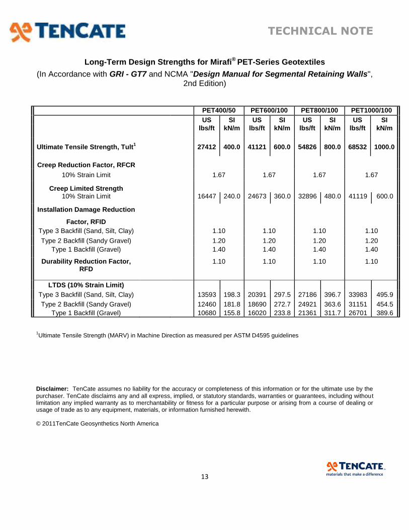
Long-Term Design Strengths for Mirafi® PET-Series Geotextiles
(In Accordance with GRI - GT7 and NCMA "Design Manual for Segmental Retaining Walls", 2nd Edition)
PET400/50 PET600/100 PET800/100 PET1000/100
US SI US SI US SI US SI
lbs/ft kN/m lbs/ft kN/m lbs/ft kN/m lbs/ft kN/m
Ultimate Tensile Strength, Tult1 27412 400.0 41121 600.0 54826 800.0 68532 1000.0
Creep Reduction Factor, RFCR
10% Strain Limit 1.67 1.67 1.67 1.67
Creep Limited Strength
10% Strain Limit 16447 240.0 24673 360.0 32896 480.0 41119 600.0
Installation Damage Reduction
Factor, RFID
Type 3 Backfill (Sand, Silt, Clay) 1.10 1.10 1.10 1.10
Type 2 Backfill (Sandy Gravel) 1.20 1.20 1.20 1.20
Type 1 Backfill (Gravel) 1.40 1.40 1.40 1.40
Durability Reduction Factor, RFD
1.10 1.10 1.10 1.10
LTDS (10% Strain Limit)
Type 3 Backfill (Sand, Silt, Clay) 13593 198.3 20391 297.5 27186 396.7 33983 495.9
Type 2 Backfill (Sandy Gravel) 12460 181.8 18690 272.7 24921 363.6 31151 454.5
Type 1 Backfill (Gravel) 10680 155.8 16020 233.8 21361 311.7 26701 389.6
1Ultimate Tensile Strength (MARV) in Machine Direction as measured per ASTM D4595 guidelines
Disclaimer: TenCate assumes no liability for the accuracy or completeness of this information or for the ultimate use by the
purchaser. TenCate disclaims any and all express, implied, or statutory standards, warranties or guarantees, including without limitation any implied warranty as to merchantability or fitness for a particular purpose or arising from a course of dealing or usage of trade as to any equipment, materials, or information furnished herewith. © 2011TenCate Geosynthetics North America