Embed Size (px)
Citation preview
DETERMINATION OF EARTHQUAKE DESIGN CRITERIA FOR FIXED
OFFSHORE PLATFORM (FOUR-LEGGED) DUE TO ACEH EARTHQUAKE IN
MALAYSIA
LIM JIA JUN
Thesis submitted in fulfilment of the requirements
for the award of the degree of
B.Eng (Hons.) Civil Engineering
Faculty of Civil Engineering and Earth Resources
UNIVERSITI MALAYSIA PAHANG
JUNE 2015
vi
ABSTRACT
The level of concern among civil engineers in Malaysia about the aspect to design the
structural for earthquake design criteria is low. But there are some countries occur
earthquake very often such as Aceh, Indonesia. Actually the tremors happened in
Malaysia region due to Aceh earthquake and it also affected fixed offshore structure in
Malaysia which the offshore structure in Malaysia are not designed to resist seismic
loading. The objective of this study is to determine the earthquake design criteria for
fixed offshore platform due to Aceh earthquake in Malaysia. The location of the fixed
offshore platform is at the Terengganu. All the environmental factors data are given
such as ranges of wave height and ground motion acceleration. The environmental
loadings such as wave and wind load have been designed by referring API (American
Petroleum Institute) design criteria. There are three types of analysis will be carry out:
Free vibration analysis, Response spectrum analysis and Time history analysis. For the
Free vibration analysis, there would have 12 mode shape of the structure. For the
Response spectrum analysis, the analysis will be performed by using response spectra
curves of EuroCode8. Time history analysis has been performed by referring to time
history earthquake Aceh 2004. The computer software SAP2000 is selected to analyse
this structure and the design code for the steel frame is EuroCode3. However, there is an
assumption have been made when doing the 3D model of the structure. The fixed
offshore platform structure is fixed to the ground instead of pilled and the soil
interaction was neglected.
vii
ABSTRAK
Tahap kebimbangan di kalangan jurutera awam di Malaysia mengenai aspek untuk
mereka bentuk struktur untuk kriteria reka bentuk gempa bumi adalah rendah. Tetapi
terdapat beberapa negara berlaku gempa bumi selalunya seperti Aceh, Indonesia.
Sebenarnya gegaran yang berlaku di rantau Malaysia berikutan gempa bumi Aceh dan
ia juga terjejas struktur luar pesisir tetap di Malaysia yang struktur luar pesisir di
Malaysia tidak direka untuk menahan beban seismik. Objektif kajian ini adalah untuk
menentukan kriteria reka bentuk gempa bumi untuk platform luar pesisir tetap akibat
gempa bumi Aceh di Malaysia. Lokasi platform luar pesisir yang ditetapkan adalah di
Terengganu. Semua faktor-faktor alam sekitar data diberikan seperti julat ketinggian
ombak dan pecutan gerakan tanah. The beban alam sekitar seperti ombak dan angin
beban telah direka dengan merujuk API (American Petroleum Institute) kriteria reka
bentuk. Terdapat tiga jenis analisis akan menjalankan: analisis getaran Percuma, analisis
spektrum Respons dan analisis sejarah Time. Untuk analisis getaran Percuma, tidak
akan mempunyai bentuk 12 mod struktur. Bagi analisis spektrum Response, analisis
akan dilakukan dengan menggunakan lengkung sambutan spektrum EuroCode8. Masa
analisis sejarah telah dijalankan dengan merujuk kepada gempa bumi sejarah masa
Aceh 2004. perisian komputer SAP2000 dipilih untuk menganalisis struktur ini dan kod
reka bentuk untuk kerangka keluli adalah EuroCode3. Walau bagaimanapun, terdapat
satu andaian telah dibuat ketika melakukan model 3D struktur. Struktur platform luar
pesisir tetap adalah tetap ke tanah bukan pilled dan interaksi tanah telah diabaikan.
viii
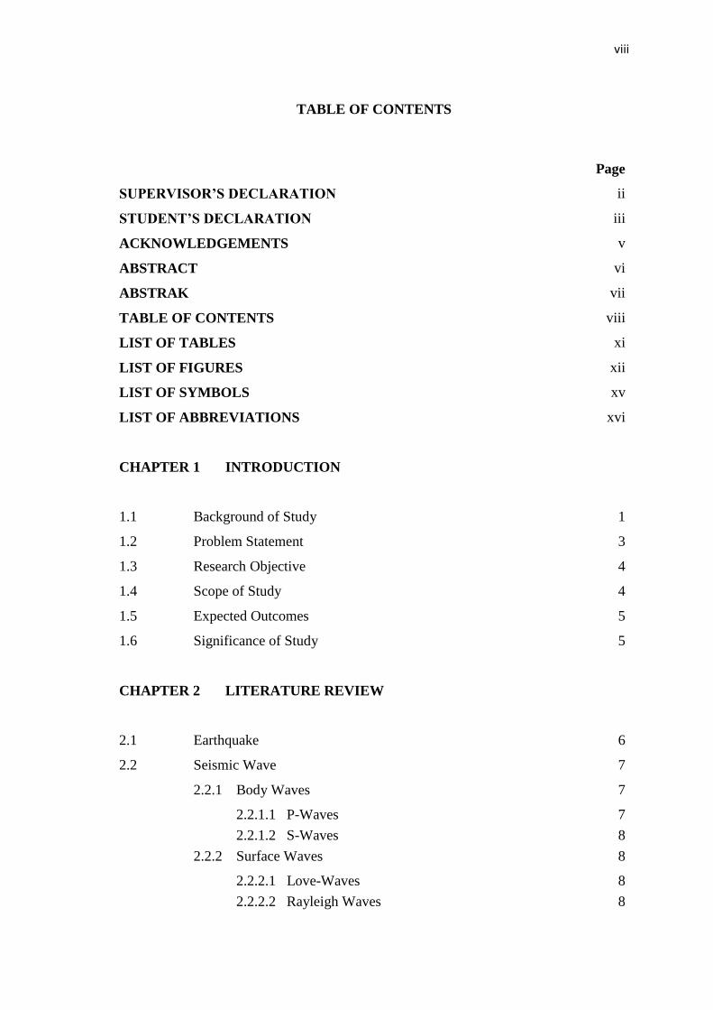
TABLE OF CONTENTS
Page
SUPERVISOR’S DECLARATION ii
STUDENT’S DECLARATION iii
ACKNOWLEDGEMENTS v
ABSTRACT vi
ABSTRAK vii
TABLE OF CONTENTS viii
LIST OF TABLES xi
LIST OF FIGURES xii
LIST OF SYMBOLS xv
LIST OF ABBREVIATIONS xvi
CHAPTER 1 INTRODUCTION
1.1 Background of Study 1
1.2 Problem Statement 3
1.3 Research Objective 4
1.4 Scope of Study 4
1.5 Expected Outcomes 5
1.6 Significance of Study 5
CHAPTER 2 LITERATURE REVIEW
2.1 Earthquake 6
2.2 Seismic Wave 7
2.2.1 Body Waves 7
2.2.1.1 P-Waves 7
2.2.1.2 S-Waves 8
2.2.2 Surface Waves 8
2.2.2.1 Love-Waves 8
2.2.2.2 Rayleigh Waves 8
ix
2.3 Causes of Earthquake 9
2.3.1 Plate Tectonics 9
2.3.2 Fault 11
2.4 Earthquake in Aceh , Indonesia 13
2.5 Measurement of Earthquake 16
2.5.1 Magnitude of an Earthquake 16
2.5.1.1 Local Magnitude Scale, ML 16
2.5.1.2 Surface Wave Magnitude Scale, Ms 17
2.5.1.3 Moment Magnitude Scale, Mw 18
2.5.2 Intensity of Ground Motion 19
2.6 Seismic Design Code 21
2.7
API Recommended Practice For Planning, Designing and
Constructing Fixed Offshore Platform By American Petroleum
Institute RP2A-WSD (2000)
22
2.8 Structures In The Offshore Environment 23
2.8.1 Fixed Offshore Platform (Jacket) 23
2.8.2 Environmental loads 24
CHAPTER 3 RESEARCH METHODOLOGY
3.1 Planning of the Study 25
3.2 Gathering the Information Data 27
3.2.1 Platform Description 27
3.2.2 Material Properties 28
3.2.3 Loading 29
3.2.3.1 Dead and Live loads 29
3.2.3.2 Environmental Loads 29
3.2.4 Earthquake Load 30
3.3 Analyses 30
3.4 Modeling 31
3.4.1 Checklist of Offshore Structure Modeling 32
3.4.2 Checklist of Computer Analysis by SAP 2000 32
3.4.3 Steps in Sap 2000 Computer Software 32
CHAPTER 4 RESULTS AND DISCUSSIONS
4.1 Introduction 53
4.1.1 Design Basis 53
x
4.1.2 Code of Practice 53
4.2 Analysis of Fixed Offshore Platform 54
4.2.1 Free vibration analysis 54
4.2.2 Dead load + Live load 57
4.2.3 Environmental load (Wind load + Wave load + Current
load) 63
4.2.4 Dead load + Live load + Environmental load + Earthquake
load 69
4.2.5 Response spectrum analysis 75
4.3 Summary of Analysis 80
4.3.1 Shear Force and Shear Stress 80
4.3.2 Bending Moment and Bending Stress 81
4.3.3 Joint Displacement 83
CHAPTER 5 CONCLUSIONS AND RECOMMENDATIONS
5.1 Conclusions 87
5.2 Recommendations 87
REFERENCES 92
APPENDICES
A Table of stiffness 94
B Table of mass 95
xi
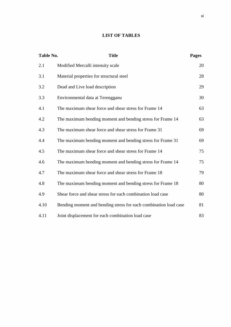
LIST OF TABLES
Table No. Title Pages
2.1 Modified Mercalli intensity scale 20
3.1 Material properties for structural steel 28
3.2 Dead and Live load description 29
3.3 Environmental data at Terengganu 30
4.1 The maximum shear force and shear stress for Frame 14 63
4.2 The maximum bending moment and bending stress for Frame 14 63
4.3 The maximum shear force and shear stress for Frame 31 69
4.4 The maximum bending moment and bending stress for Frame 31 69
4.5 The maximum shear force and shear stress for Frame 14 75
4.6 The maximum bending moment and bending stress for Frame 14 75
4.7 The maximum shear force and shear stress for Frame 18 79
4.8 The maximum bending moment and bending stress for Frame 18 80
4.9 Shear force and shear stress for each combination load case 80
4.10 Bending moment and bending stress for each combination load case 81
4.11 Joint displacement for each combination load case 83
xii
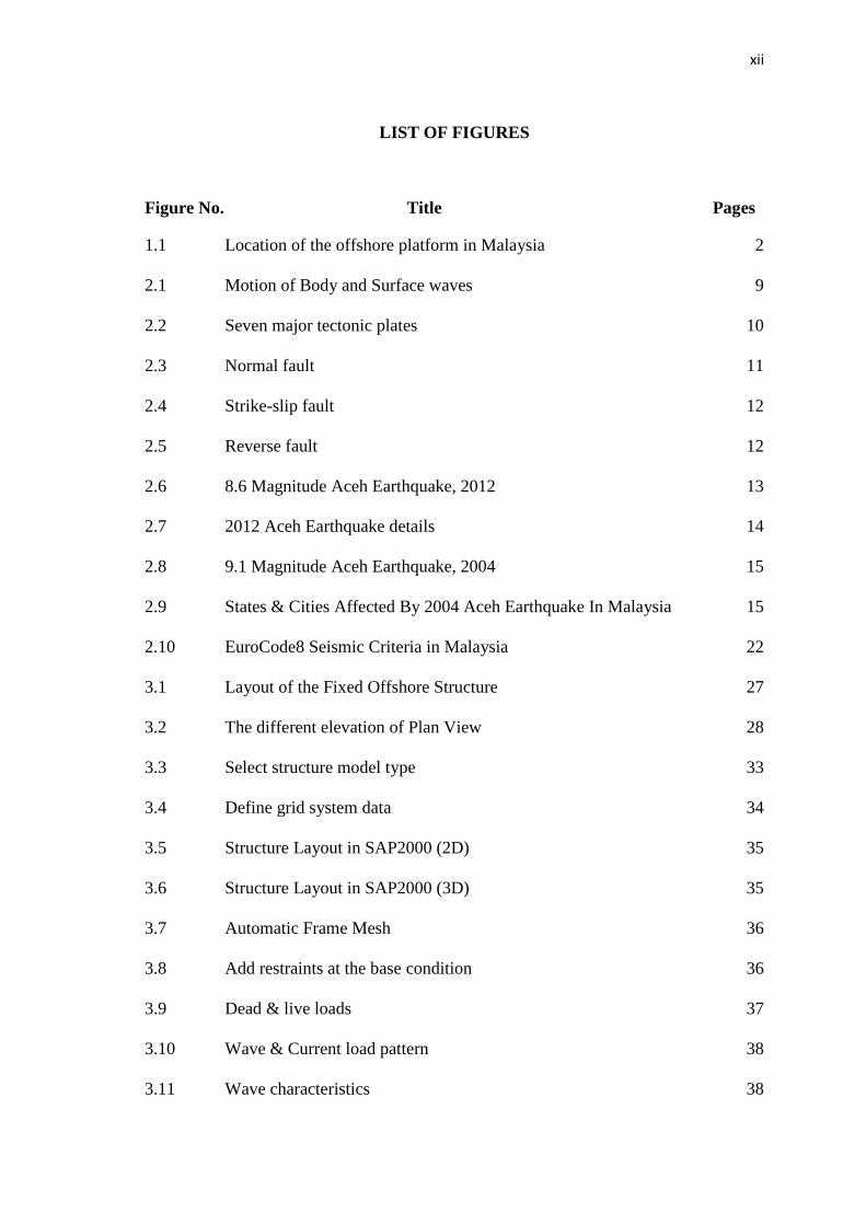
LIST OF FIGURES
Figure No. Title Pages
1.1 Location of the offshore platform in Malaysia 2
2.1 Motion of Body and Surface waves 9
2.2 Seven major tectonic plates 10
2.3 Normal fault 11
2.4 Strike-slip fault 12
2.5 Reverse fault 12
2.6 8.6 Magnitude Aceh Earthquake, 2012 13
2.7 2012 Aceh Earthquake details 14
2.8 9.1 Magnitude Aceh Earthquake, 2004 15
2.9 States & Cities Affected By 2004 Aceh Earthquake In Malaysia 15
2.10 EuroCode8 Seismic Criteria in Malaysia 22
3.1 Layout of the Fixed Offshore Structure 27
3.2 The different elevation of Plan View 28
3.3 Select structure model type 33
3.4 Define grid system data 34
3.5 Structure Layout in SAP2000 (2D) 35
3.6 Structure Layout in SAP2000 (3D) 35
3.7 Automatic Frame Mesh 36
3.8 Add restraints at the base condition 36
3.9 Dead & live loads 37
3.10 Wave & Current load pattern 38
3.11 Wave characteristics 38
xiii
3.12 Wave Plot 39
3.13 Frame Span Wave & Current Loads 40
3.14 Wind load pattern 40
3.15 Wind load properties 41
3.16 Frame open structure wind load 42
3.17 Raw earthquake data in notepad 42
3.18 Concrete after compression test 43
3.19 Water absorption graph result 44
3.20 Linear modal history 45
3.21 Time history load cases 45
3.22 Response spectrum function 46
3.23 Response spectrum EC8 2004 function definition 47
3.24 Response spectrum load case data 48
3.25 Modal load case 49
3.26 Dead + Live load cases 50
3.27 Environmental load cases 50
3.28 Dead + Live + Environmental + Earthquake load cases 51
3.29 Response spectrum load cases 52
4.1 Mode shapes 1-3 55
4.2 Mode shape 4-6 55
4.3 Mode shape 7-9 56
4.4 Mode shape 10-12 56
4.5 Modal periods and frequencies 57
4.6 Critical member Frame 14 in P-M interaction ratios 58
4.7 Frame 14 shear force model display 59
xiv
4.8 Frame 14 bending moment model display 59
4.9 Shear force and bending moment diagram for Frame 14 60
4.10 Critical member Frame 31 in P-M interaction ratios 64
4.11 Frame 31 shear force model display 65
4.12 Frame 31 bending moment model display 65
4.13 Shear force and bending moment diagram for Frame 31 66
4.14 Critical member Frame 14 in P-M interaction ratios 70
4.15 Frame 14 shear force model display 71
4.16 Frame 14 bending moment model display 71
4.17 Shear force and bending moment diagram for Frame 14 72
4.18 Critical member Frame 18 in P-M interaction ratios 76
4.19 Shear force and bending moment diagram for Frame 18 76
4.20 Shear stress versus each combination load case 81
4.21 Bending stress versus each combination load case 82
4.22 Joint displacement U1 versus each combination load case 83
4.23 Joint displacement U2 versus each combination load case 84
4.24 Joint displacement U3 versus each combination load case 84
5.1 Sabah Earthquake Magnitude 6 88
5.2 USGS shake map for Sabah 89
5.3 Wall cracked due to Ranau earthquake 90
5.4 Column failed due to Ranau Earthquake 90
5.5 Basement car park column failed due to Ranau Earthquake 91

xv
LIST OF SYMBOLS
mm Millimeter
N/mm2 Newton per millimeter square
kg Kilogram
N Newton
kN Kilo newton
kN/m2 Kilo newton per meter square
sec second
kNm Kilo newton meter
xvi
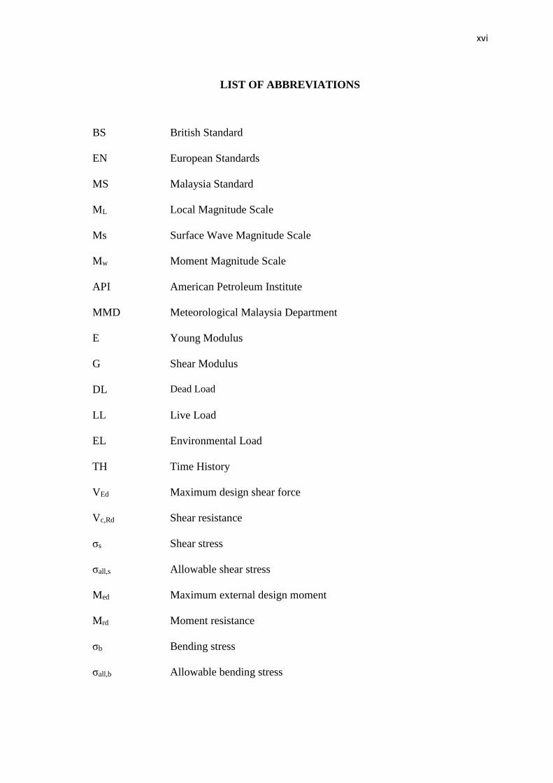
LIST OF ABBREVIATIONS
BS British Standard
EN European Standards
MS Malaysia Standard
ML Local Magnitude Scale
Ms Surface Wave Magnitude Scale
Mw Moment Magnitude Scale
API American Petroleum Institute
MMD Meteorological Malaysia Department
E Young Modulus
G Shear Modulus
DL Dead Load
LL Live Load
EL Environmental Load
TH Time History
VEd Maximum design shear force
Vc,Rd Shear resistance
σs Shear stress
σall,s Allowable shear stress
Med Maximum external design moment
Mrd Moment resistance
σb Bending stress
σall,b Allowable bending stress
CHAPTER 1
INTRODUCTION
1.1 BACKGROUND OF STUDY
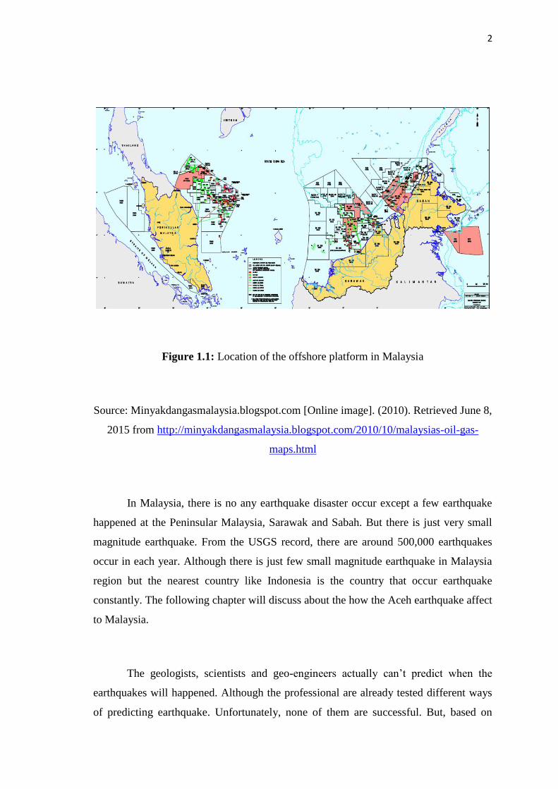
In Malaysia, there are several areas that have existing offshore platform structure
operate 24 hours all the day. Mostly the existing offshore platform structures are at
Terengganu, Sabah and Sarawak. A fixed offshore platform is a large marine structure
with facilities to process, extract oil and natural gas, and temporary to store some
product such as petroleum until it can bring to shore and run the business. At the
Terengganu, Sabah and Sarawak, most of the existing offshore platform structures are
owned by PETRONAS. There is the figure that regarding the location of the offshore
platform in Malaysia.
2
Figure 1.1: Location of the offshore platform in Malaysia
Source: Minyakdangasmalaysia.blogspot.com [Online image]. (2010). Retrieved June 8,
2015 from http://minyakdangasmalaysia.blogspot.com/2010/10/malaysias-oil-gas-
maps.html
In Malaysia, there is no any earthquake disaster occur except a few earthquake
happened at the Peninsular Malaysia, Sarawak and Sabah. But there is just very small
magnitude earthquake. From the USGS record, there are around 500,000 earthquakes
occur in each year. Although there is just few small magnitude earthquake in Malaysia
region but the nearest country like Indonesia is the country that occur earthquake
constantly. The following chapter will discuss about the how the Aceh earthquake affect
to Malaysia.
The geologists, scientists and geo-engineers actually can’t predict when the
earthquakes will happened. Although the professional are already tested different ways
of predicting earthquake. Unfortunately, none of them are successful. But, based on
3
some particular or certain fault, they can analyze where will be another earthquake
happen in the future, but there is no other way to know when the earthquake will happen
in future. By using the modern seismic code (EuroCode8) to minimize the damage
caused by earthquake in future.
The seismic waves is created by earthquake when the Earth’s crust sudden
release of energy. The earthquakes are measured by using seismometers. If the
Magnitude is less than or equal to 3, that will consider almost imperceptible or weak. If
the Magnitude is 3 to 7, that will causing massive damage to the larger areas, it is
depending on their depth. The largest earthquakes happened in historic times is the
magnitude 9 over, there is no limit for a significant values of magnitude.
1.2 PROBLEM STATEMENT
In this research project, the problem statement is to determine necessary of the
seismic hazard consideration for offshore platform (four-legged) in Malaysia region due
to Aceh earthquake.
The hazard consideration is needed to take into account because the earthquake
from the Aceh was affected the offshore platform structure in Malaysia. Especially the
area that's near the country, Indonesia, for example Penang. But the most of the offshore
structures get affected at Terengganu, Sabah and Sarawak. Although the building
structures inside Malaysia region is safe but it can’t ensure that the offshore structure is
safe from the large magnitude scale of earthquake, such as Aceh earthquake. As
mentioned before, even the specialist scientist also can’t predict when the earthquake
will occur and earthquake can be happened in anytime and in any place. So, the
necessarily to increase the safety factor and design offshore structure with seismic code
need to be consider in order to encounter the seismic load.
4
1.3 RESEARCH OBJECTIVE
The aims of this research are:
i. To estimate the earthquake ground motion due to Aceh earthquake for
assessment of offshore platform (four-legged) in Malaysia.
ii. To determine the vulnerability of existing offshore platform (four-legged) in
Malaysia when subjected to earthquake load from Aceh
iii. To determine the earthquake design criteria for offshore platform (four-
legged) located in Malaysia.
1.4 SCOPE OF STUDY
In the proposed study, the effect of the typical offshore platform due to the Aceh
earthquake will be investigated. In this research, the study of the architectural drawing
of a typical four-legged fixed offshore platform will be done. The case study will be
related to the Aceh earthquake that affected the offshore platform in Malaysia region.
The modeling of offshore platform structure and analysis software used is SAP 2000.
This research recommended to test the typical offshore platform by using three analyses.
There are:
i. Free vibration analysis
ii. Response spectrum earthquake analysis
iii. Time history earthquake analysis
5
1.5 EXPECTED OUTCOME/S
The expected outcome of the analysis results will show the responses of the
fixed offshore platform structure due to Aceh earthquake and all the outcome of the
analysis will be done by using analysis software, SAP2000.
1.6 SIGNIFICANCE OF STUDY
The outcomes and findings of this research is to study and analyse the behaviour
and stability of 4-legged fixed offshore structures in the Malaysia region due to Aceh
earthquake. It may be useful for seismic behaviour assessment of typical fixed offshore
platform (four-legged) and contribute to understanding the effect of accounting
parameters of seismic performance of existing offshore structure. The analysis results
obtained from the earthquake analysis may be used to develop some earthquake design
criteria to increase the safety of factor of fixed offshore structure located in Malaysia
region to prevent the damage caused from Aceh earthquake.
CHAPTER 2
LITERATURE REVIEW
2.1 EARTHQUAKE
An earthquake is created when the Earth’s crust is perform sudden motion.
According to geologists, before existence of human, the earth has suffered earthquakes
for millions years. When came to the nineteenth century, the geologists started to make
the measurement for recording the earthquake data. They collected all the seismological
data from many earthquakes and analyzed to map and tried to understand the
phenomena of earthquakes. The geologists used these data were to resolve the earth’s
internal structure and they success to a remarkable degree, which will help towards the
development of seismology and to explain the causes of earthquakes. The study of
collecting seismological data will also helped in the design of building structure to resist
earthquakes. (Datta, 2010)
There is always be the first concerned of safety of the building structure when
the earthquake is happening and the seismic load is created to affect the structural
design of building. But, the economic loss and serviceability are also of concern.
(Ucl.ac.uk, 2015) To understand what the seismic loading is, there is a thing that need to
know. The seismic loading is totally different from the gravity loading, it will cause
7
the different behavior under these two difference loadings. Seismic loading is required
more specific detailed analysis to ensure the elastic range is beyond the seismic
performance. When the building structure experiences earthquake, it will caused
structural damage. And it can be expected because all building codes are only allow the
inelastic energy. Which the normal buildings only can resist inelastic energy and the
loading caused by dead load and live load will dissipate in structural systems. (Tze Khai,
2008)
2.2 SEISMIC WAVE
During an earthquake occur, it will released large strain energy and the seismic
waves will travel in all directions through the Earth’s layers. These seismic waves will
refracting and reflecting at each interface. (Ucl.ac.uk, 2015)
2.2.1 Body Waves
Body wave, one of the type of the wave in seismic wave. In the Body wave,
there are P-waves and S-waves. Below are the characteristics of the P-waves and S-
waves:
2.2.1.1 P-Waves
It is also called Pressure waves or Primary waves. It is longitudinal waves, it is
involve in compression and expansion. P-waves is the fastest waves travelling in solids
and it is also the first wave appear on a seismogram. It can traveling in both form of
material, fluids and solids.
8
2.2.1.2 S-Waves
It is also called Shear waves or Secondary waves. The type of wave is transverse
waves because it moved in perpendicularly to the direction of propagation. In the
seismogram, S-waves is appear later after P-waves. And it can only traveling in solids
because there is no shear resistances in fluids. This type of waves have the good impact
on ground surface movement.
2.2.2 Surface Waves
Surface waves, another type of wave in Seismic waves. In the Surface waves,
there are also two categories of waves, there are Love-waves and Rayleigh waves. The
description is shown at below:
2.2.2.1 Love-Waves
Love waves are similar to S waves. When the waves are travelling close to the
ground surface, they are transverse shear waves.
2.2.2.2 Rayleigh Waves
The Rayleigh wave, the particle motion of these waves is like vertical plane that
having the direction of propagation and retrogrades elliptically. This type of wave is
moving like the propagation of ocean waves because the biggest displacements of the
particle at the surface. Rayleigh waves have the properties that dispersion, its
wavelength keep changing and the velocity is not constant. So this type of wave is not
stable in acceleration movement. (Ucl.ac.uk, n.d.)
9
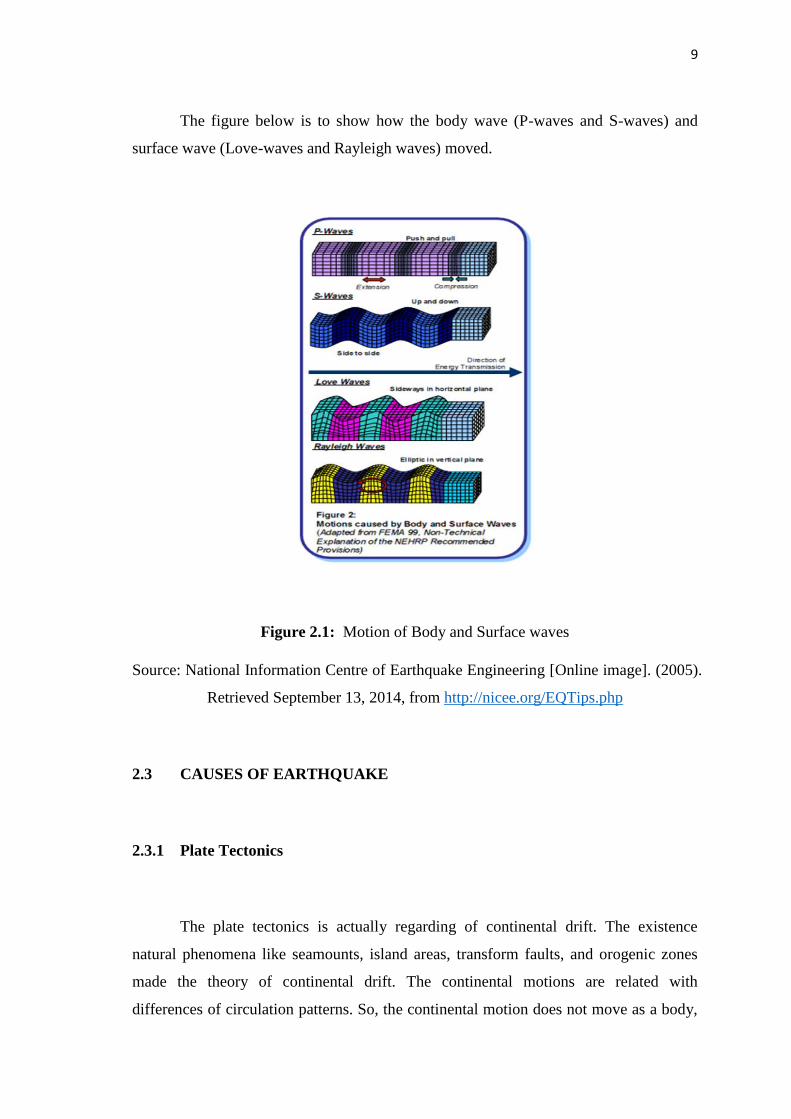
The figure below is to show how the body wave (P-waves and S-waves) and
surface wave (Love-waves and Rayleigh waves) moved.
Figure 2.1: Motion of Body and Surface waves
Source: National Information Centre of Earthquake Engineering [Online image]. (2005).
Retrieved September 13, 2014, from http://nicee.org/EQTips.php
2.3 CAUSES OF EARTHQUAKE
2.3.1 Plate Tectonics
The plate tectonics is actually regarding of continental drift. The existence
natural phenomena like seamounts, island areas, transform faults, and orogenic zones
made the theory of continental drift. The continental motions are related with
differences of circulation patterns. So, the continental motion does not move as a body,

10
it is moving or occurs through the sliding of the lithosphere in pieces, it called tectonic
plates. There are seven major tectonic plates, as shown in Figure 3.
Figure 2.2: Seven major tectonic plates
Source: National Information Centre of Earthquake Engineering [Online image]. (2005).
Retrieved September 23, 2014 from http:// nicee.org/EQTips.php
The tectonic plates are moving relative to each other, it can be move in both of
direction and magnitude, both at the plate boundaries, inside the plates and leads to an
accumulation of strain. The plates accumulates the strain energy will overcome any
resistance and causes slip between the two sides of the fault. Because of the sudden slip,
it release large amounts of energy and causing elastic rebound, which constitutes or is
the earthquake. (Tze Khai, 2008)
11
2.3.2 Fault
The plate boundaries at the location of earthquake occur are called fault. This
type of earthquakes are in terms of interpolate earthquakes. When the earthquakes occur
within the plate away from the faults, this type of earthquake are called intraplate
earthquakes. Which sudden release of energy because of rock beds are slips together.
These slips creating the new faults are called earthquake faults. There are the typical
terms to describe different types of faults:
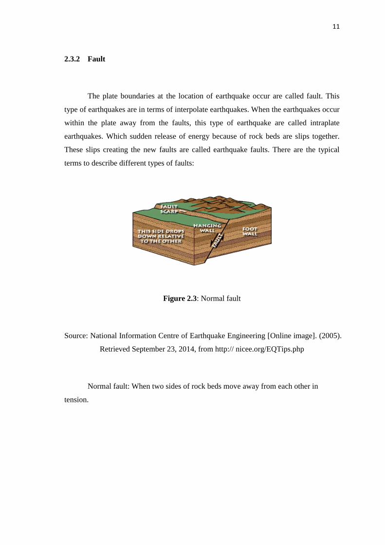
Figure 2.3: Normal fault
Source: National Information Centre of Earthquake Engineering [Online image]. (2005).
Retrieved September 23, 2014, from http:// nicee.org/EQTips.php
Normal fault: When two sides of rock beds move away from each other in
tension.
12
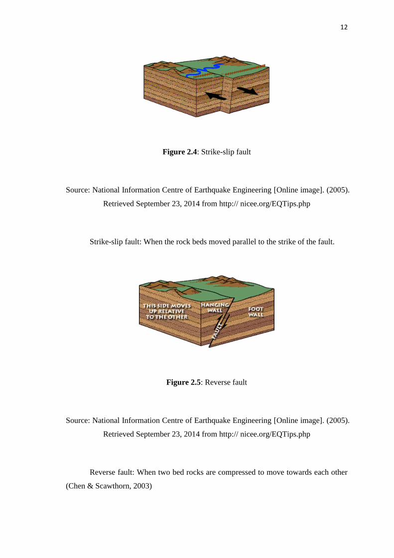
Figure 2.4: Strike-slip fault
Source: National Information Centre of Earthquake Engineering [Online image]. (2005).
Retrieved September 23, 2014 from http:// nicee.org/EQTips.php
Strike-slip fault: When the rock beds moved parallel to the strike of the fault.
Figure 2.5: Reverse fault
Source: National Information Centre of Earthquake Engineering [Online image]. (2005).
Retrieved September 23, 2014 from http:// nicee.org/EQTips.php
Reverse fault: When two bed rocks are compressed to move towards each other
(Chen & Scawthorn, 2003)