Embed Size (px)
Citation preview
980358-001 Rev. A
©2001 Zebra Technologies Corporation
244328242844
DesktopThermal PrintersService Manual

ii 980358-001 Rev. A
FOREWARD
This manual provides spares replacement and service information for the LP 2443, LP 2824,TLP 2824, LP 2844, and TLP2844 series printers, manufactured by Zebra TechnologiesCorporation, Camarillo, California.
TECHNICAL SUPPORT
If for any reason you require product technical support, please contact the Distributor where you firstpurchased your equipment. If they cannot help you or at their direction, contact Zebra RepairAdministration.
RETURN MATERIALS AUTHORIZATION
Before returning any equipment to Zebra for in warranty or out of warranty repair, contact RepairAdministration for a Return Materials Authorization (RMA) number. Repack the equipment in theoriginal packing material and mark the RMA number clearly on the outside. Ship the equipment,freight prepaid, to the address listed below:
Zebra RMA, USA1001 Flynn Road
Camarillo, CA. 93012Phone: +1 (805) 579-1800
Label Printers: Card Printers:Zebra International, Europe Zebra International, Europe
Zebra House, The Valley Centre Zone Indutrielle, Rue d'AmsterdamGordon Road, High Wycombe 44370 Varades, France
Buckinghamshire HP13 6EQ, United Kingdom Phone: +33 (0) 240 097 070Phone: +44 (0) 1494 472872 FAX: +33 (0) 240 834 745
FAX: +44 (0) 1494 450103
COPYRIGHT NOTICE
This document contains information proprietary to Zebra Technologies Corporation. This documentand the information contained within is copyrighted by Zebra Technologies Corporation and maynot be duplicated in full or in part by any person without written approval from Zebra. While everyeffort has been made to keep the information contained within current and accurate as of the date ofpublication, no guarantee is given or implied that the document is error-free or that it is accuratewith regard to any specification. Zebra reserves the right to make changes, for the purpose ofproduct improvement, at any time.
980358-001 Rev. A iii
TRADEMARKS
LP 2824, TLP 2824, LP 2844, TLP 2844 and 2443 are service marks of Zebra TechnologiesCorporation. Windows and MS-DOS are registered trademarks of Microsoft Corp. All other marksare trademarks or registered trademarks of their respective holders.
OPERATOR CAUTIONS AND WARNINGS
These pages describe general safety and maintenance procedures that an operator must follow.They are referenced throughout the service manual. The manual may include other warnings andcautions not displayed here.
Warning - Shock Hazard
The printer should never be operated in a location where it can get wet.Personal injury could result.
Warning - Static Discharge
The discharge of electrostatic energy that accumulates on the surface ofthe human body or other surfaces can damage or destroy the print head orelectronic components used in this device. TAKE ANTI-STATICPRECAUTIONS before handling the print head or the electroniccomponents under the print head assembly.
Caution - Printer Setup & Handling
1)When installing or modifying the printer setup or configuration,ALWAYS TURN POWER OFF Before:
A) Connecting any cables.B) Performing any cleaning or maintenance operations.C) Moving the printer.
2) Damage to the printer interface connector, accessories or enclosuremay result from placing the printer on it’s front bezel or backside duringunpacking or handling.
iv 980358-001 Rev. A
Media Cautions & Tips
1) Always use high quality approved labels and tags. Approved suppliescan be ordered from your dealer.
2) If poor quality, adhesive backed labels are used, that DO NOT lay flat onthe backing liner, the exposed edges may stick to the label guides androllers inside the printer, causing the label to peel off from the liner andjam the printer.
3) DO NOT use non-approved transfer ribbon. Permanent damage to theprint head may result if a non-approved ribbon is used. Non-approvedribbons maybe wound incorrectly for the printer or contain chemicals thatmay damage the print head.
4) IMPORTANT - If a transfer ribbon is installed incorrectly by theoperator, damage to the print head may result.
5) DO NOT use a ribbon when printing with direct thermal media.
Media Reload Tip
If you should run out of labels or ribbon while printing, DO NOT turn thepower switch OFF (0) while reloading or data loss may occur. The printerwill automatically resume printing when a new label or ribbon roll isloaded.
Print Quality Tip
Print density (darkness) is affected by the heat energy (density setting)applied and by the print speed. Changing both Print Speed and Densitymay be required to achieve the desired results.
980358-001 Rev. A v

vi 980358-001 Rev. A
CONTENTS
INTRODUCTION 1
Models . . . . . . . . . . . . . . . . . . . . . . . . . . . . . . . . . . . . . . . . . . . 2Conventions . . . . . . . . . . . . . . . . . . . . . . . . . . . . . . . . . . . . . . . . 3Unpacking the Printer . . . . . . . . . . . . . . . . . . . . . . . . . . . . . . . . . . . 3Preparing a Static-Safe Work Area . . . . . . . . . . . . . . . . . . . . . . . . . . . . . 3Environmental and Shock Protection. . . . . . . . . . . . . . . . . . . . . . . . . . . . 4
CLEANING AND MAINTENANCE 5
General Cleaning. . . . . . . . . . . . . . . . . . . . . . . . . . . . . . . . . . . . . . 5Cleaning the Media Path . . . . . . . . . . . . . . . . . . . . . . . . . . . . . . . . . . 6Before Loading Media . . . . . . . . . . . . . . . . . . . . . . . . . . . . . . . . . . . 6Cleaning the Print Head . . . . . . . . . . . . . . . . . . . . . . . . . . . . . . . . . . 7Lubrication . . . . . . . . . . . . . . . . . . . . . . . . . . . . . . . . . . . . . . . . . 7
TROUBLESHOOTING GUIDE 9
Print Head Wear . . . . . . . . . . . . . . . . . . . . . . . . . . . . . . . . . . . . . 12
REQUIRED TOOLS 13
2844 and 2443 PARTS 15
Latch, LP 2844 Replacement . . . . . . . . . . . . . . . . . . . . . . . . . . . . . . . 17Top Cover Replacement - LP 2844. . . . . . . . . . . . . . . . . . . . . . . . . . . . 18Print Head, LP 2844 Replacement . . . . . . . . . . . . . . . . . . . . . . . . . . . . 20Packing Materials Replacement - 2844 . . . . . . . . . . . . . . . . . . . . . . . . . . 22Feet Replacement - 2844 . . . . . . . . . . . . . . . . . . . . . . . . . . . . . . . . . 23Front Bezel Replacement - 2844 . . . . . . . . . . . . . . . . . . . . . . . . . . . . . 24Front/Cutter Bezel Replacement - 2844 . . . . . . . . . . . . . . . . . . . . . . . . . . 25Platen Replacement - 2844 . . . . . . . . . . . . . . . . . . . . . . . . . . . . . . . . 26Bottom Case (Base Housing) Replacement - 2844 . . . . . . . . . . . . . . . . . . . . 27Motor Replacement - 2844 . . . . . . . . . . . . . . . . . . . . . . . . . . . . . . . . 28Black Line and Bottom Gap Sensors Replacement - 2844 . . . . . . . . . . . . . . . . 29Head-Up Sensor Replacement - 2844. . . . . . . . . . . . . . . . . . . . . . . . . . . 30Main Print Circuit Board Assembly Replacement - 2844 . . . . . . . . . . . . . . . . . 31Dispenser Bezel Replacement - 2844 . . . . . . . . . . . . . . . . . . . . . . . . . . . 32Latch Replacement - TLP 2844 . . . . . . . . . . . . . . . . . . . . . . . . . . . . . . 33Cover Support Replacement - TLP 2844 . . . . . . . . . . . . . . . . . . . . . . . . . 34Hinge Replacement - TLP 2844. . . . . . . . . . . . . . . . . . . . . . . . . . . . . . 35Upper Case (Top Cover) Replacement - TLP 2844. . . . . . . . . . . . . . . . . . . . 36Ribbon Carriage Replacement - TLP 2844 . . . . . . . . . . . . . . . . . . . . . . . . 37Feed Button/LED and Top Gap Sensor Replacement - TLP 2844 . . . . . . . . . . . . 38Ribbon Motion Sensor Replacement - TLP 2844 . . . . . . . . . . . . . . . . . . . . . 40Real Time Clock Option - 2844 . . . . . . . . . . . . . . . . . . . . . . . . . . . . . . 41Print Head Replacement - TLP 2844 . . . . . . . . . . . . . . . . . . . . . . . . . . . 42
980358-001 Rev. A vii
2824 PARTS 45
Feet Replacement - 2824 . . . . . . . . . . . . . . . . . . . . . . . . . . . . . . . . . 47Front Bezel Replacement - 2824 . . . . . . . . . . . . . . . . . . . . . . . . . . . . . 48Front/Cutter Bezel Replacement - 2824 . . . . . . . . . . . . . . . . . . . . . . . . . . 49Platen Replacement - 2824 . . . . . . . . . . . . . . . . . . . . . . . . . . . . . . . . 50Bottom Case (Lower Cover) Replacement - 2824. . . . . . . . . . . . . . . . . . . . . 51Motor Replacement - 2824 . . . . . . . . . . . . . . . . . . . . . . . . . . . . . . . . 52Black Line and Bottom Gap Sensors Replacement - 2824 . . . . . . . . . . . . . . . . 53Main Printed Circuit Board Assembly (PCBA) Replacement - 2824 . . . . . . . . . . . . 54Dispenser Bezel Replacement - 2824 . . . . . . . . . . . . . . . . . . . . . . . . . . . 55Latch Replacement - LP 2824. . . . . . . . . . . . . . . . . . . . . . . . . . . . . . . 56Upper Case (Top Cover) Replacement - LP 2824. . . . . . . . . . . . . . . . . . . . . 57Feed/Gap Sensor Cable Assembly Replacement - LP 2824 . . . . . . . . . . . . . . . . 58Feed/LED PCBA Replacement - LP 2824. . . . . . . . . . . . . . . . . . . . . . . . . 59Real Time Clock Option - 2824 . . . . . . . . . . . . . . . . . . . . . . . . . . . . . . 60Print Head, LP 2824 Replacement . . . . . . . . . . . . . . . . . . . . . . . . . . . . 61
CABLE ROUTING 63
TLP 2844 Cable Routing . . . . . . . . . . . . . . . . . . . . . . . . . . . . . . . . . 64LP 2844 and LP 2443 Cable Routing . . . . . . . . . . . . . . . . . . . . . . . . . . . 65LP 2824 Cable Routing . . . . . . . . . . . . . . . . . . . . . . . . . . . . . . . . . . 66
viii 980358-001 Rev. A

INTRODUCTION
If you are a field engineer or technician, this manual helps you with routine maintenance,troubleshooting and procedures for replacing parts for repair.
Follow the parts replacement procedures as closely as possible. If you are unsure of any procedure,please contact your service representative or call the products technical support group at ZebraTechnologies Corporation, (805) 579-1800.
Zebra Technologies stocks all replacement parts for the printer. Be sure your facility stocks sufficientparts for the printer so that scheduled maintenance can take place in a timely manner.
980358-001 Rev. A 1
Models
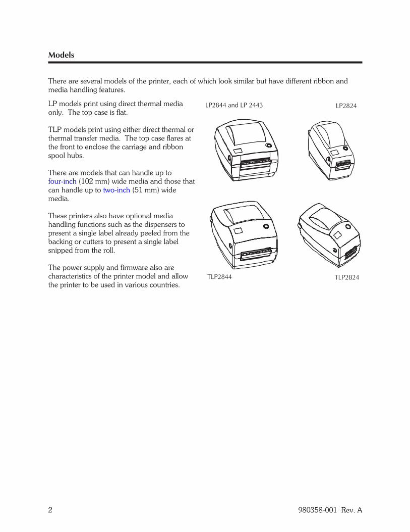
There are several models of the printer, each of which look similar but have different ribbon andmedia handling features.
LP models print using direct thermal mediaonly. The top case is flat.
TLP models print using either direct thermal orthermal transfer media. The top case flares atthe front to enclose the carriage and ribbonspool hubs.
There are models that can handle up tofour-inch (102 mm) wide media and those thatcan handle up to two-inch (51 mm) widemedia.
These printers also have optional mediahandling functions such as the dispensers topresent a single label already peeled from thebacking or cutters to present a single labelsnipped from the roll.
The power supply and firmware also arecharacteristics of the printer model and allowthe printer to be used in various countries.
2 980358-001 Rev. A
Conventions
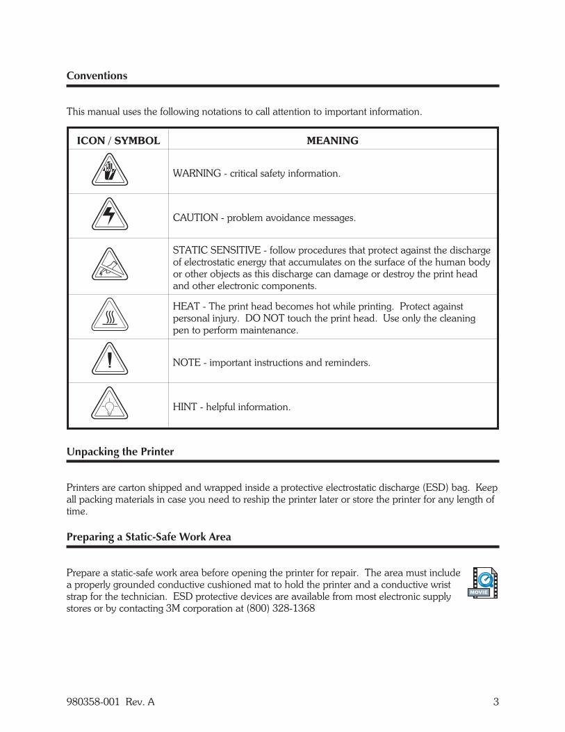
This manual uses the following notations to call attention to important information.
ICON / SYMBOL MEANING
WARNING - critical safety information.
CAUTION - problem avoidance messages.
STATIC SENSITIVE - follow procedures that protect against the dischargeof electrostatic energy that accumulates on the surface of the human bodyor other objects as this discharge can damage or destroy the print headand other electronic components.
HEAT - The print head becomes hot while printing. Protect againstpersonal injury. DO NOT touch the print head. Use only the cleaningpen to perform maintenance.
NOTE - important instructions and reminders.
HINT - helpful information.
Unpacking the Printer
Printers are carton shipped and wrapped inside a protective electrostatic discharge (ESD) bag. Keepall packing materials in case you need to reship the printer later or store the printer for any length oftime.
Preparing a Static-Safe Work Area
Prepare a static-safe work area before opening the printer for repair. The area must includea properly grounded conductive cushioned mat to hold the printer and a conductive wriststrap for the technician. ESD protective devices are available from most electronic supplystores or by contacting 3M corporation at (800) 328-1368
980358-001 Rev. A 3
MOVIE

Environmental and Shock Protection
Extreme temperature and humidity fluctuations or mishandling can damage the printer and powersupply.
Allow 30 minutes or more before opening the printer's plastic bag. This time allows the printer tostabilize temperature especially after storage in a cool, dry location and then placement in a warmer,more humid location. Warm, humid air condenses on the cool components of the printer and thiscondensation may damage the components.
Move the printer carefully. Mechanical damage can certainly result from falls or rough handling.
4 980358-001 Rev. A

CLEANING AND MAINTENANCE
The printers are manufactured and tested under a strict quality management program. ZebraTechnologies uses only high quality components and materials in its printers. Although onlyminimal routine maintenance is required, following these simple maintenance guidelines will ensurelonger life with quality printing performance.
General Cleaning
Keep the outside your printer clean by periodically wiping it with a soft cloth dampened with water.Do not use abrasive cleaners as they will damage the surfaces.
Shock Hazard - See page iv. Always turn off the printer before cleaning.
980358-001 Rev. A 5
Cleaning the Media Path
Keep the inside of your printer clean as needed, by using a brush, vacuum or air blower along themedia path (except the print head).
If a label jams inside the printer, remove the label and any adhesive residue immediately. Adhesivemay spread throughout the printer's media path if not completely removed. Many adhesive arepermanent and have short "set" times.
If the platen, dispenser bar, or serrated tear bar require cleaning, use 70% isopropyl alcoholabsorbed into a clean, lint-free cloth to wipe these surfaces. To turn the platen, use your finger toadvance the platen gear. However, if the platen is designed for linerless media, do not use alcohol.
If the cutter requires cleaning, turn the printer off. Use tweezers to remove the media. Never usesolutions or solvents to clean the blade. If necessary, turn the printer on and use the C programmingcommand to cycle the cutter several times to perform a self cleaning operation. See the EPL2programmer's manual.
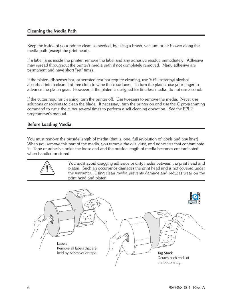
Before Loading Media
You must remove the outside length of media (that is, one, full revolution of labels and any liner).When you remove this part of the media, you remove the oils, dust, and adhesives that contaminateit. Tape or adhesive holds the loose end and the outside length of media becomes contaminatedwhen handled or stored.
You must avoid dragging adhesive or dirty media between the print head andplaten. Such an occurrence damages the print head and is not covered underthe warranty. Using clean media prevents damage and reduces wear on theprint head and platen.
6 980358-001 Rev. A
MOVIE
Cleaning the Print Head
When handled during installation, and over time, the print head may become contaminatedresulting in poor print quality. After installing a new print head or after using a roll of mediaor ribbon, rub the cleaning pen across the dark area of the print head. Allow the print headto dry for one minute before loading labels.
Avoid touching the print head whenever possible. To remove dirt or dust,always gently clean the print head with a cleaning pen or a cotton swabmoistened with 70% isopropyl alcohol.
Lubrication
None of the serviceable parts require additional lubrication.
980358-001 Rev. A 7
MOVIE

8 980358-001 Rev. A
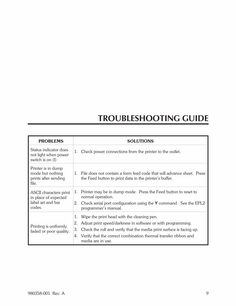
TROUBLESHOOTING GUIDE
PROBLEMS SOLUTIONS
Status indicator doesnot light when powerswitch is on (I)
1. Check power connections from the printer to the outlet.
Printer is in dumpmode but nothingprints after sendingfile.
1. File does not contain a form feed code that will advance sheet. Pressthe Feed button to print data in the printer’s buffer.
ASCII characters printin place of expectedlabel art and barcodes.
1. Printer may be in dump mode. Press the Feed button to reset tonormal operation.
2. Check serial port configuration using the Y command. See the EPL2programmer’s manual.
Printing is uniformlyfaded or poor quality.
1. Wipe the print head with the cleaning pen.2. Adjust print speed/darkness in software or with programming.3. Check the roll and verify that the media print surface is facing up.4. Verify that the correct combination thermal transfer ribbon and
media are in use.
980358-001 Rev. A 9
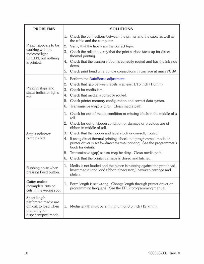
PROBLEMS SOLUTIONS
Printer appears to beworking with theindicator lightGREEN, but nothingis printed.
1. Check the connections between the printer and the cable as well asthe cable and the computer.
2. Verify that the labels are the correct type.3. Check the roll and verify that the print surface faces up for direct
thermal printing.4. Check that the transfer ribbon is correctly routed and has the ink side
down.5. Check print head wire bundle connections in carriage at main PCBA.
Printing stops andstatus indicator lightsred
1. Perform the AutoSense adjustment.2. Check that gap between labels is at least 1/16 inch (1.6mm)3. Check for media jam.4. Check that media is correctly routed.5. Check printer memory configuration and correct data syntax.6. Transmissive (gap) is dirty. Clean media path.
Status indicatorremains red.
1. Check for out-of-media condition or missing labels in the middle of aroll.
2. Check for out-of-ribbon condition or damage or previous use ofribbon in middle of roll.
3. Check that the ribbon and label stock or correctly routed4. If using direct thermal printing, check that programmed mode or
printer driver is set for direct thermal printing. See the programmer’sbook for details.
5. Transmissive (gap) sensor may be dirty. Clean media path.6. Check that the printer carriage is closed and latched.
Rubbing noise whenpressing Feed button.
1. Media is not loaded and the platen is rubbing against the print head.Insert media (and load ribbon if necessary) between carriage andplaten.
Cutter makesincomplete cuts orcuts in the wrong spot.
1. Form length is set wrong. Change length through printer driver orprogramming language. See the EPL2 programming manual.
Short length,perforated media aredifficult to load whenpreparing fordispenser/peel mode.
1. Media length must be a minimum of 0.5 inch (12.7mm).
10 980358-001 Rev. A
980358-001 Rev. A 11
PROBLEMS SOLUTIONS
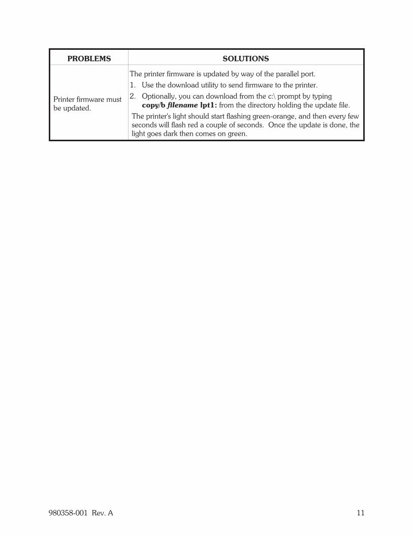
Printer firmware mustbe updated.
The printer firmware is updated by way of the parallel port.1. Use the download utility to send firmware to the printer.2. Optionally, you can download from the c:\ prompt by typing
copy/b filename lpt1: from the directory holding the update file.The printer's light should start flashing green-orange, and then every fewseconds will flash red a couple of seconds. Once the update is done, thelight goes dark then comes on green.
Print Head Wear
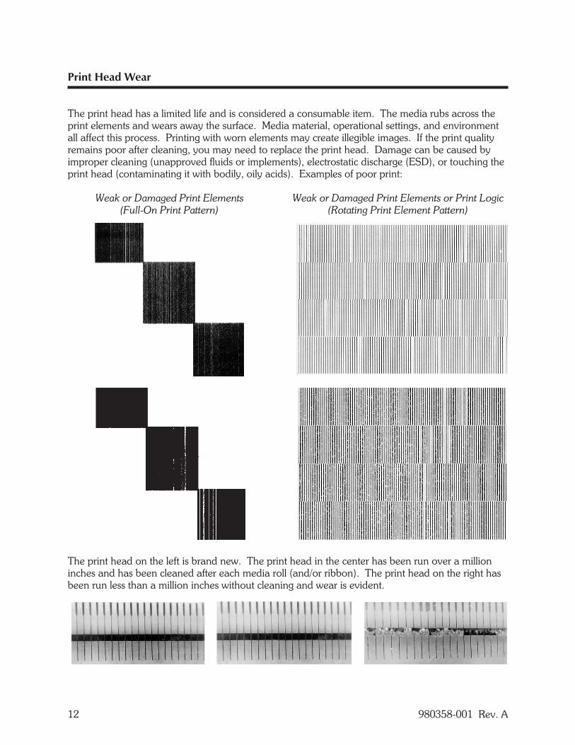
The print head has a limited life and is considered a consumable item. The media rubs across theprint elements and wears away the surface. Media material, operational settings, and environmentall affect this process. Printing with worn elements may create illegible images. If the print qualityremains poor after cleaning, you may need to replace the print head. Damage can be caused byimproper cleaning (unapproved fluids or implements), electrostatic discharge (ESD), or touching theprint head (contaminating it with bodily, oily acids). Examples of poor print:
Weak or Damaged Print Elements Weak or Damaged Print Elements or Print Logic(Full-On Print Pattern) (Rotating Print Element Pattern)
The print head on the left is brand new. The print head in the center has been run over a millioninches and has been cleaned after each media roll (and/or ribbon). The print head on the right hasbeen run less than a million inches without cleaning and wear is evident.
12 980358-001 Rev. A

REQUIRED TOOLS
Make use of the following tools while performing replacement procedures:
• Phillips driver #0• Phillips driver #1• Phillips driver #2• Slot-head screwdriver• tweezers• needle-nose pliers• pliers for integrated chips
980358-001 Rev. A 13

14 980358-001 Rev. A
2844 and 2443 PARTS
The 2844 printers have a four-inch print width. Both the LP and TLP models can print on directthermal media. The TLP model can also print using ribbons and thermal transfer media. Thissection includes procedures that are specific to the 2844 printers.
The 2443 printer is similar in most respects to the LP2844 printer. Both are direct-thermal printers.
980358-001 Rev. A 15
16 980358-001 Rev. A
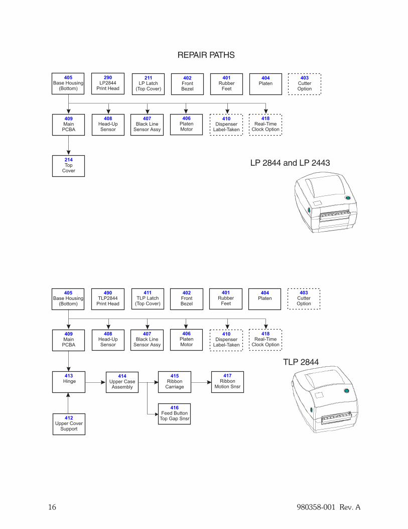
211
LP Latch(Top Cover)
404
Platen401
RubberFeet
408
Head-UpSensor
403
CutterOption
410
DispenserLabel-Taken
407
Black LineSensor Assy
406
PlatenMotor
418
Real-TimeClock Option
402
FrontBezel
405
Base Housing(Bottom)
409
MainPCBA
TLP 2844
REPAIR PATHS
290
LP2844Print Head
LP 2844 and LP 2443
411
TLP Latch(Top Cover)
404
Platen401
RubberFeet
408
Head-UpSensor
403
CutterOption
416
Feed ButtonTop Gap Snsr
410
DispenserLabel-Taken
407
Black LineSensor Assy
406
PlatenMotor
418
Real-TimeClock Option
412
Upper CoverSupport
402
FrontBezel
405
Base Housing(Bottom)
409
MainPCBA
413
Hinge414
Upper CaseAssembly
415
RibbonCarriage
490
TLP2844Print Head
417
RibbonMotion Snsr
214
TopCover
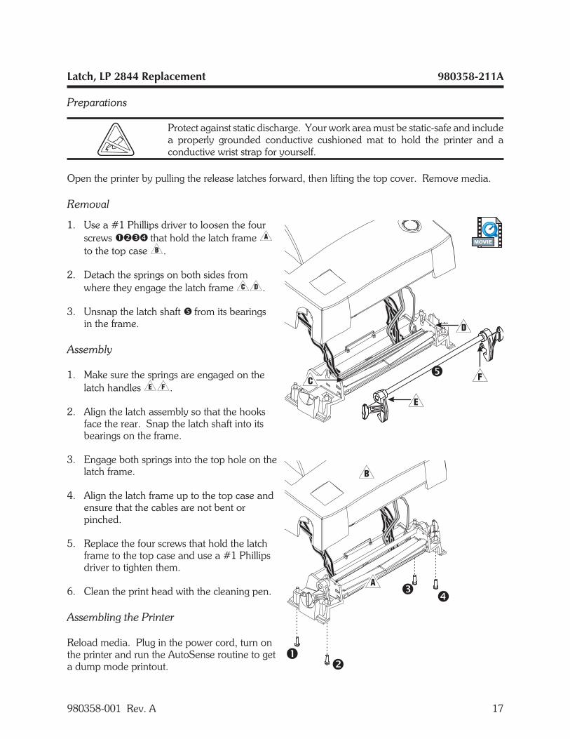
Latch, LP 2844 Replacement 980358-211A
Preparations
Protect against static discharge. Your work area must be static-safe and includea properly grounded conductive cushioned mat to hold the printer and aconductive wrist strap for yourself.
Open the printer by pulling the release latches forward, then lifting the top cover. Remove media.
Removal
1. Use a #1 Phillips driver to loosen the fourscrews ���� that hold the latch frame�to the top case�.
2. Detach the springs on both sides fromwhere they engage the latch frame��.
3. Unsnap the latch shaft � from its bearingsin the frame.
Assembly
1. Make sure the springs are engaged on thelatch handles��.
2. Align the latch assembly so that the hooksface the rear. Snap the latch shaft into itsbearings on the frame.
3. Engage both springs into the top hole on thelatch frame.
4. Align the latch frame up to the top case andensure that the cables are not bent orpinched.
5. Replace the four screws that hold the latchframe to the top case and use a #1 Phillipsdriver to tighten them.
6. Clean the print head with the cleaning pen.
Assembling the Printer
Reload media. Plug in the power cord, turn onthe printer and run the AutoSense routine to geta dump mode printout.
980358-001 Rev. A 17
MOVIE
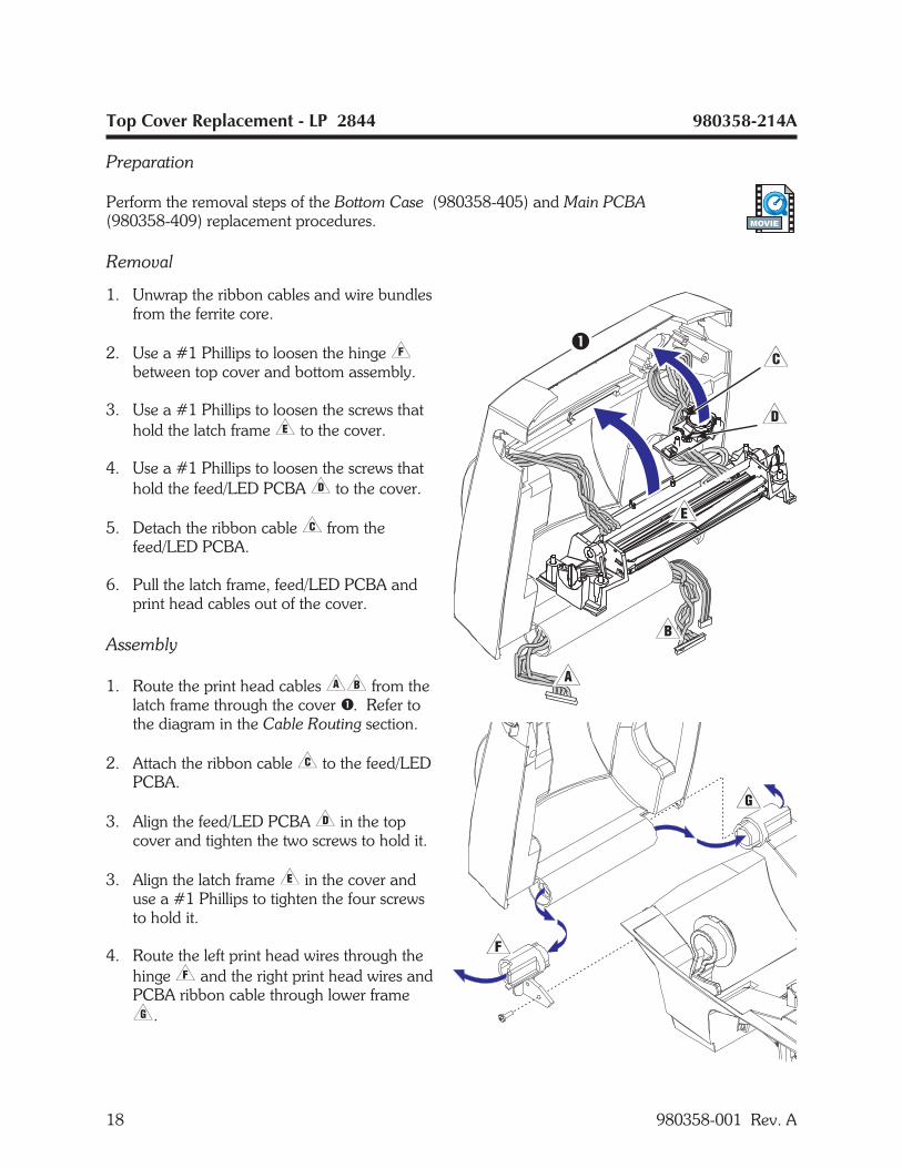
Top Cover Replacement - LP 2844 980358-214A
Preparation
Perform the removal steps of the Bottom Case (980358-405) and Main PCBA(980358-409) replacement procedures.
Removal
1. Unwrap the ribbon cables and wire bundlesfrom the ferrite core.
2. Use a #1 Phillips to loosen the hinge�between top cover and bottom assembly.
3. Use a #1 Phillips to loosen the screws thathold the latch frame� to the cover.
4. Use a #1 Phillips to loosen the screws thathold the feed/LED PCBA� to the cover.
5. Detach the ribbon cable� from thefeed/LED PCBA.
6. Pull the latch frame, feed/LED PCBA andprint head cables out of the cover.
Assembly
1. Route the print head cables�� from thelatch frame through the cover �. Refer tothe diagram in the Cable Routing section.
2. Attach the ribbon cable� to the feed/LEDPCBA.
3. Align the feed/LED PCBA� in the topcover and tighten the two screws to hold it.
3. Align the latch frame� in the cover anduse a #1 Phillips to tighten the four screwsto hold it.
4. Route the left print head wires through thehinge� and the right print head wires andPCBA ribbon cable through lower frame�.
18 980358-001 Rev. A
MOVIE

Top Cover Replacement - LP 2844 (continued) 980358-214A
5. Align the hinge in place and use a #1 Phillips to tighten the single screw that holds it.
Assembling the Printer
Perform the assembly steps of the Main PCBA (980358-409) and Bottom Case (980358-405)replacement procedures.
980358-001 Rev. A 19
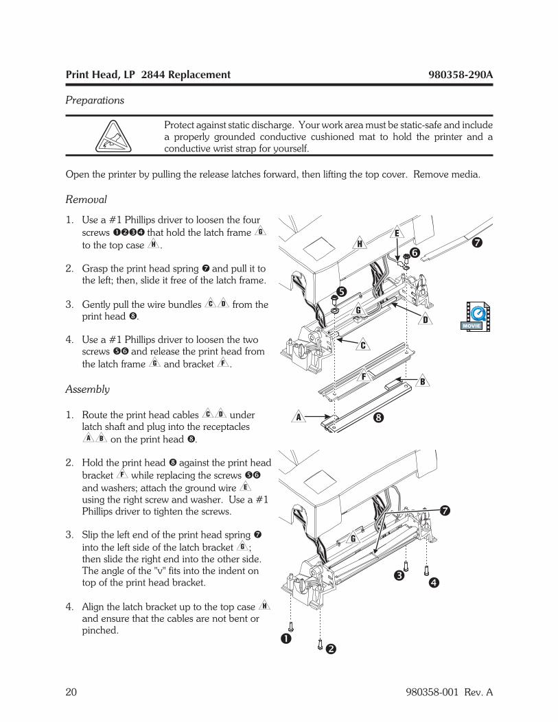
Print Head, LP 2844 Replacement 980358-290A
Preparations
Protect against static discharge. Your work area must be static-safe and includea properly grounded conductive cushioned mat to hold the printer and aconductive wrist strap for yourself.
Open the printer by pulling the release latches forward, then lifting the top cover. Remove media.
Removal
1. Use a #1 Phillips driver to loosen the fourscrews ���� that hold the latch frame�to the top case�.
2. Grasp the print head spring � and pull it tothe left; then, slide it free of the latch frame.
3. Gently pull the wire bundles�� from theprint head �.
4. Use a #1 Phillips driver to loosen the twoscrews �� and release the print head fromthe latch frame� and bracket�.
Assembly
1. Route the print head cables�� underlatch shaft and plug into the receptacles�� on the print head �.
2. Hold the print head � against the print headbracket� while replacing the screws ��and washers; attach the ground wire�using the right screw and washer. Use a #1Phillips driver to tighten the screws.
3. Slip the left end of the print head spring �into the left side of the latch bracket�;then slide the right end into the other side.The angle of the "v" fits into the indent ontop of the print head bracket.
4. Align the latch bracket up to the top case�and ensure that the cables are not bent orpinched.
20 980358-001 Rev. A
MOVIE

Print Head, LP 2844 Replacement 980358-290A
5. Replace the four screws that hold the latch bracket to the top case and use a #1 Phillips driver totighten them.
6. Clean the print head with the cleaning pen.
Assembling the Printer
Reload media. Plug in the power cord, turn on the printer and run the AutoSense routine to get adump mode printout.
980358-001 Rev. A 21
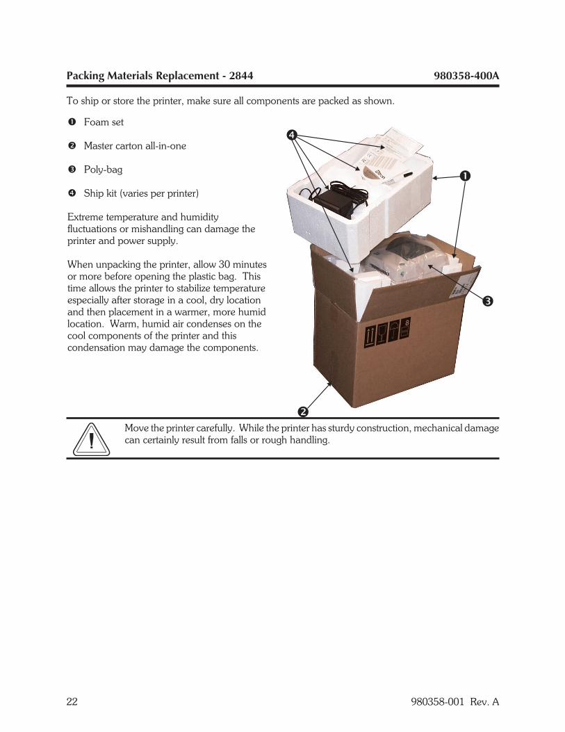
Packing Materials Replacement - 2844 980358-400A
To ship or store the printer, make sure all components are packed as shown.
Move the printer carefully. While the printer has sturdy construction, mechanical damagecan certainly result from falls or rough handling.
22 980358-001 Rev. A
� Foam set
� Master carton all-in-one
� Poly-bag
� Ship kit (varies per printer)
Extreme temperature and humidityfluctuations or mishandling can damage theprinter and power supply.
When unpacking the printer, allow 30 minutesor more before opening the plastic bag. Thistime allows the printer to stabilize temperatureespecially after storage in a cool, dry locationand then placement in a warmer, more humidlocation. Warm, humid air condenses on thecool components of the printer and thiscondensation may damage the components.
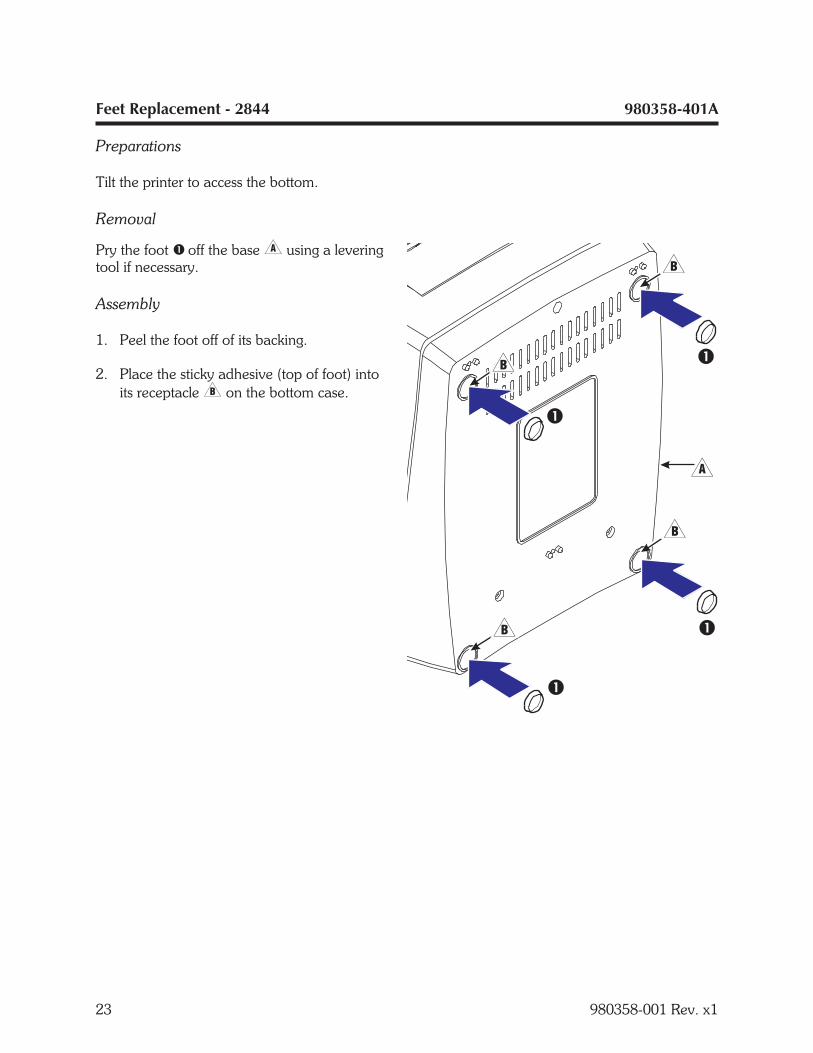
Feet Replacement - 2844 980358-401A
Preparations
Tilt the printer to access the bottom.
Removal
Pry the foot � off the base� using a leveringtool if necessary.
Assembly
1. Peel the foot off of its backing.
2. Place the sticky adhesive (top of foot) intoits receptacle� on the bottom case.
23 980358-001 Rev. x1
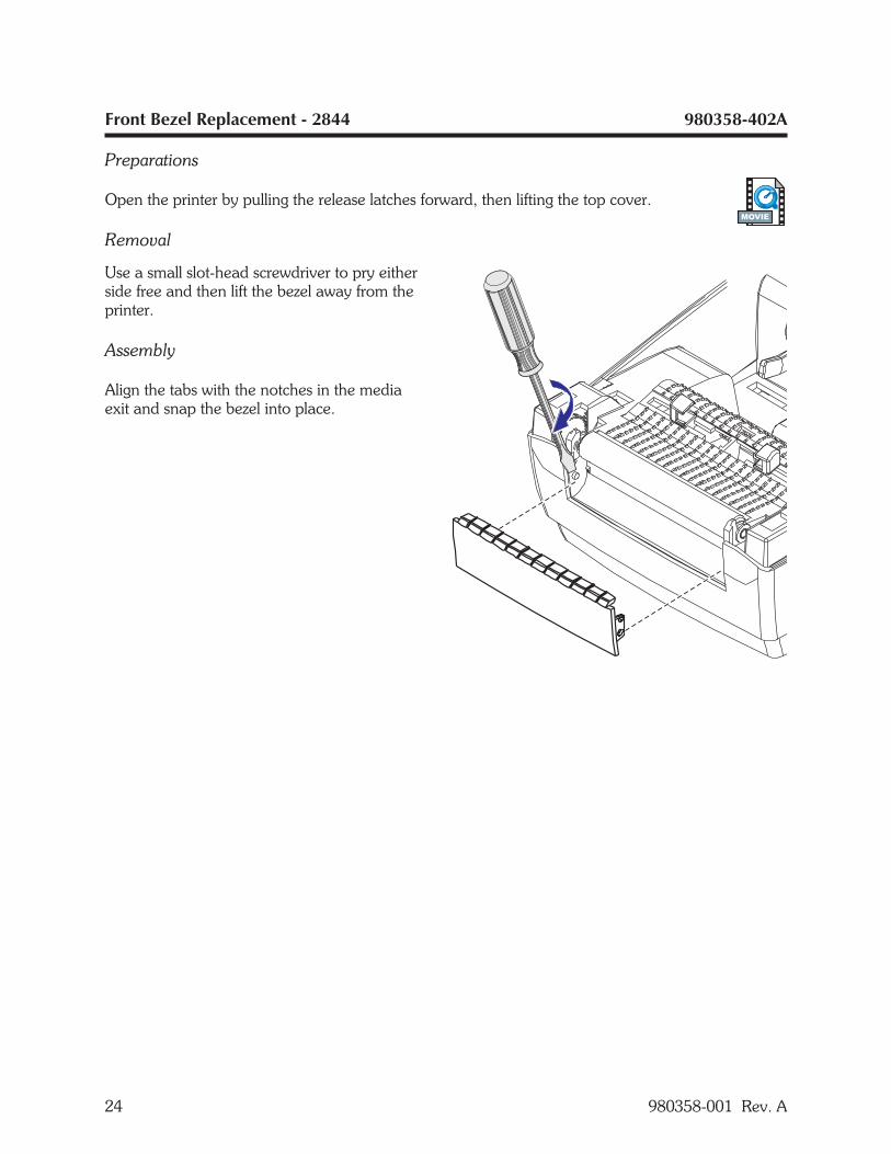
Front Bezel Replacement - 2844 980358-402A
Preparations
Open the printer by pulling the release latches forward, then lifting the top cover.
Removal
Use a small slot-head screwdriver to pry eitherside free and then lift the bezel away from theprinter.
Assembly
Align the tabs with the notches in the mediaexit and snap the bezel into place.
24 980358-001 Rev. A
MOVIE
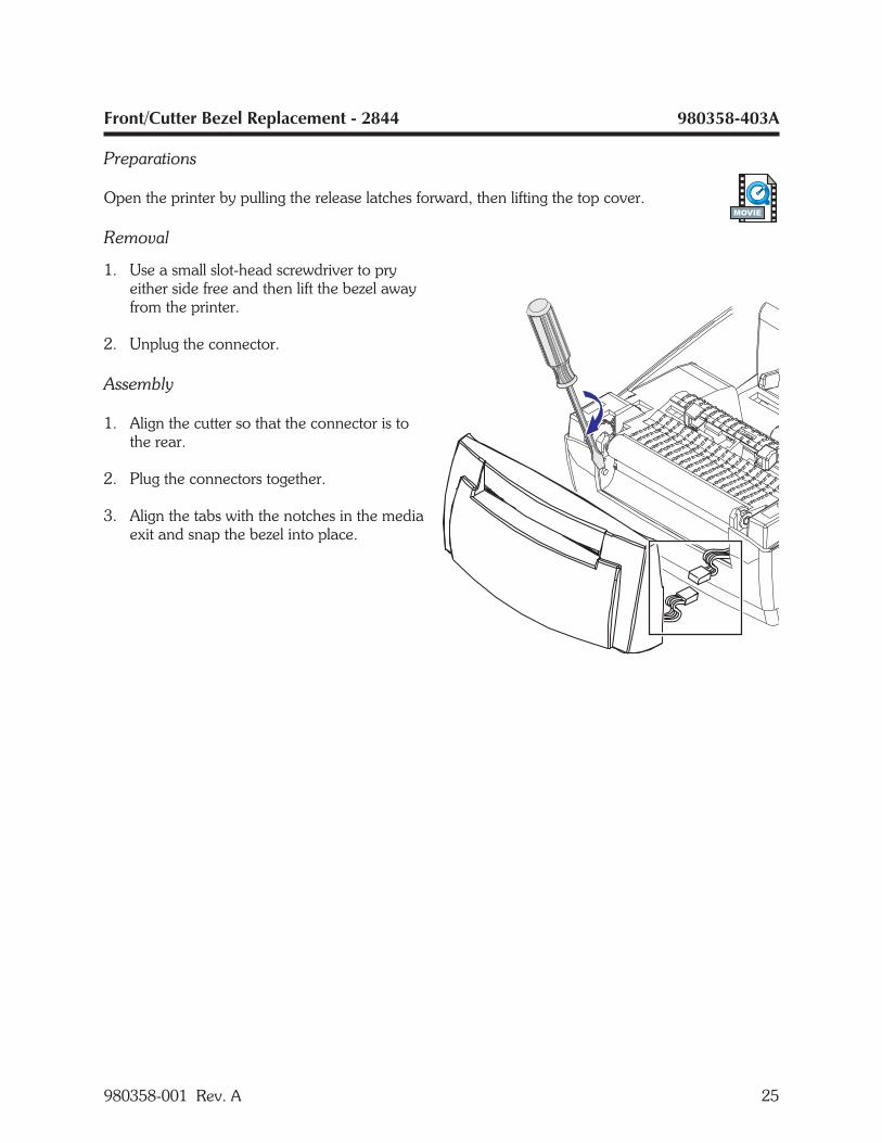
Front/Cutter Bezel Replacement - 2844 980358-403A
Preparations
Open the printer by pulling the release latches forward, then lifting the top cover.
Removal
1. Use a small slot-head screwdriver to pryeither side free and then lift the bezel awayfrom the printer.
2. Unplug the connector.
Assembly
1. Align the cutter so that the connector is tothe rear.
2. Plug the connectors together.
3. Align the tabs with the notches in the mediaexit and snap the bezel into place.
980358-001 Rev. A 25
MOVIE
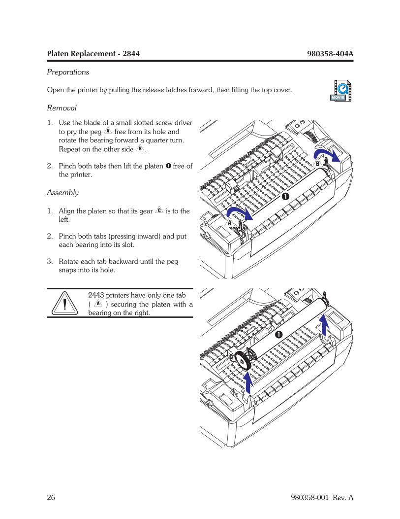
Platen Replacement - 2844 980358-404A
Preparations
Open the printer by pulling the release latches forward, then lifting the top cover.
Removal
1. Use the blade of a small slotted screw driverto pry the peg� free from its hole androtate the bearing forward a quarter turn.Repeat on the other side�.
2. Pinch both tabs then lift the platen � free ofthe printer.
Assembly
1. Align the platen so that its gear� is to theleft.
2. Pinch both tabs (pressing inward) and puteach bearing into its slot.
3. Rotate each tab backward until the pegsnaps into its hole.
2443 printers have only one tab( � ) securing the platen with abearing on the right.
26 980358-001 Rev. A
MOVIE
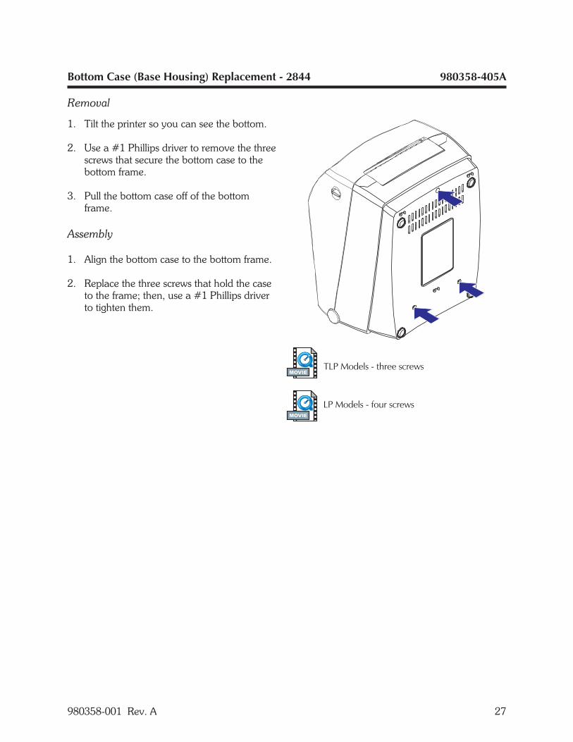
Bottom Case (Base Housing) Replacement - 2844 980358-405A
Removal
1. Tilt the printer so you can see the bottom.
2. Use a #1 Phillips driver to remove the threescrews that secure the bottom case to thebottom frame.
3. Pull the bottom case off of the bottomframe.
Assembly
1. Align the bottom case to the bottom frame.
2. Replace the three screws that hold the caseto the frame; then, use a #1 Phillips driverto tighten them.
980358-001 Rev. A 27
MOVIE
MOVIE
Motor Replacement - 2844 980358-406A
Preparations
Protect against static discharge. Your work area must be static-safe and includea properly grounded conductive cushioned mat to hold the printer and aconductive wrist strap for yourself.
Perform the removal steps of the Bottom Case Replacement procedure (980358-405).
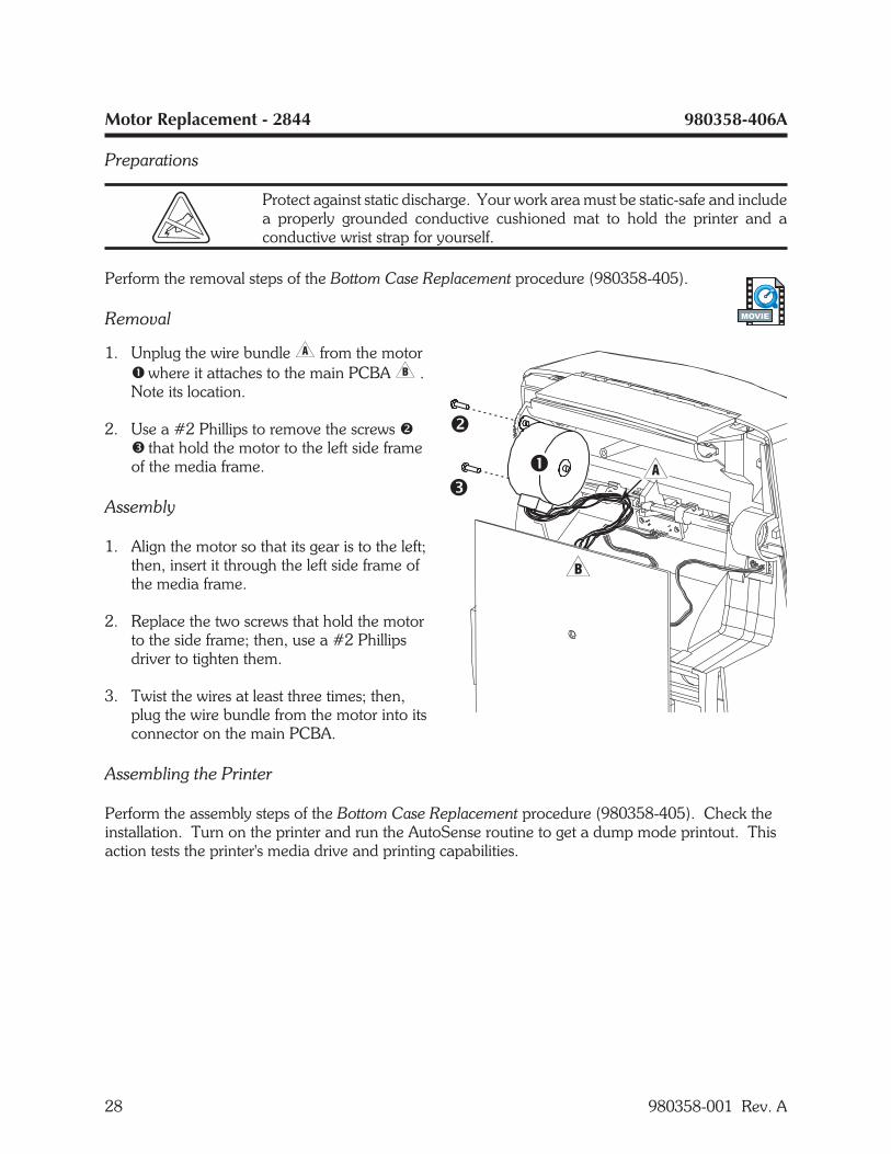
Removal
1. Unplug the wire bundle� from the motor� where it attaches to the main PCBA� .Note its location.
2. Use a #2 Phillips to remove the screws �� that hold the motor to the left side frameof the media frame.
Assembly
1. Align the motor so that its gear is to the left;then, insert it through the left side frame ofthe media frame.
2. Replace the two screws that hold the motorto the side frame; then, use a #2 Phillipsdriver to tighten them.
3. Twist the wires at least three times; then,plug the wire bundle from the motor into itsconnector on the main PCBA.
Assembling the Printer
Perform the assembly steps of the Bottom Case Replacement procedure (980358-405). Check theinstallation. Turn on the printer and run the AutoSense routine to get a dump mode printout. Thisaction tests the printer's media drive and printing capabilities.
28 980358-001 Rev. A
MOVIE
Black Line and Bottom Gap Sensors Replacement - 2844 980358-407A
Preparations
Protect against static discharge. Your work area must be static-safe and includea properly grounded conductive cushioned mat to hold the printer and aconductive wrist strap for yourself.
Perform the removal steps of the Bottom Case Replacement procedure (980358-405).
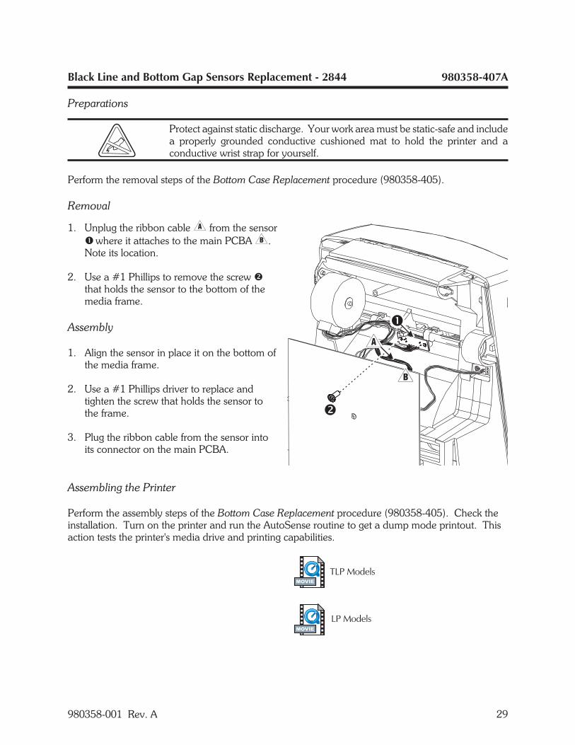
Removal
1. Unplug the ribbon cable� from the sensor� where it attaches to the main PCBA�.Note its location.
2. Use a #1 Phillips to remove the screw �that holds the sensor to the bottom of themedia frame.
Assembly
1. Align the sensor in place it on the bottom ofthe media frame.
2. Use a #1 Phillips driver to replace andtighten the screw that holds the sensor tothe frame.
3. Plug the ribbon cable from the sensor intoits connector on the main PCBA.
Assembling the Printer
Perform the assembly steps of the Bottom Case Replacement procedure (980358-405). Check theinstallation. Turn on the printer and run the AutoSense routine to get a dump mode printout. Thisaction tests the printer's media drive and printing capabilities.
980358-001 Rev. A 29
MOVIE
MOVIE
Head-Up Sensor Replacement - 2844 980358-408A
Preparations
Protect against static discharge. Your work area must be static-safe and includea properly grounded conductive cushioned mat to hold the printer and aconductive wrist strap for yourself.
Perform the removal steps of the Bottom Case Replacement procedure (980358-405).
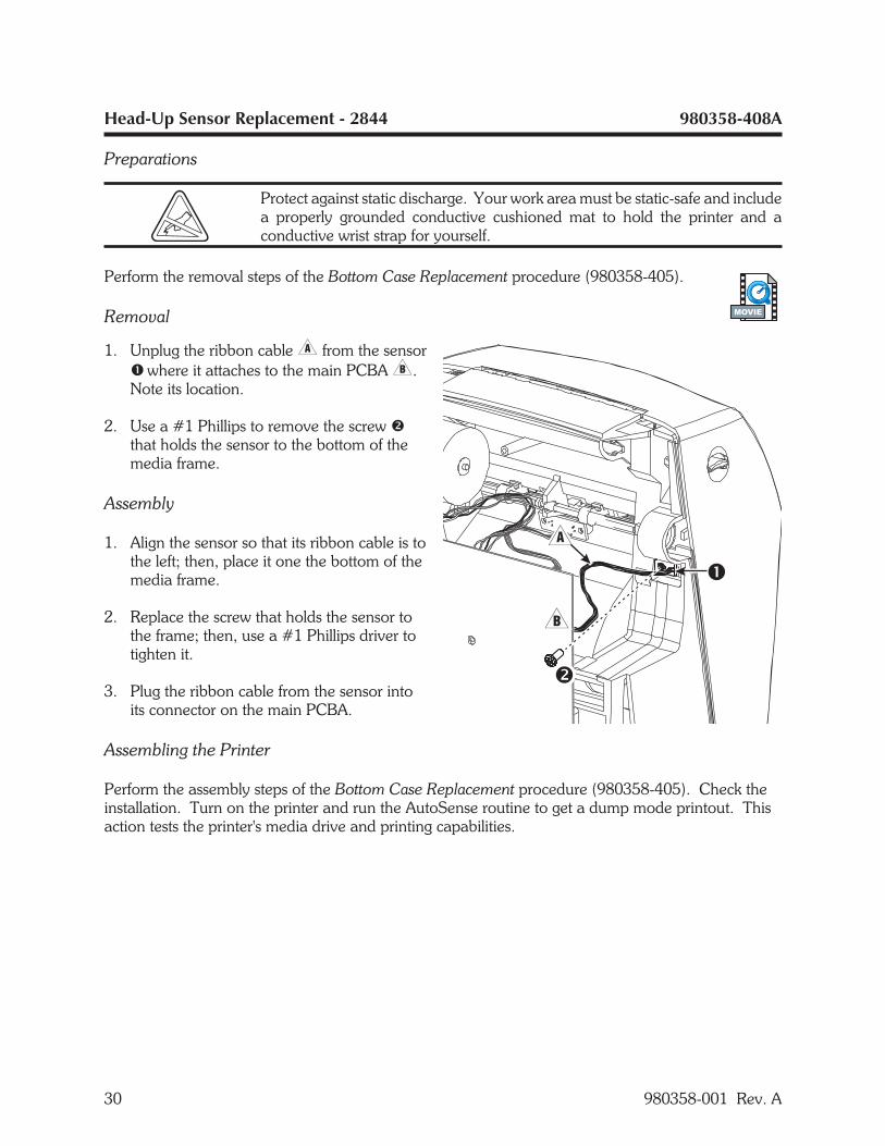
Removal
1. Unplug the ribbon cable� from the sensor� where it attaches to the main PCBA�.Note its location.
2. Use a #1 Phillips to remove the screw �that holds the sensor to the bottom of themedia frame.
Assembly
1. Align the sensor so that its ribbon cable is tothe left; then, place it one the bottom of themedia frame.
2. Replace the screw that holds the sensor tothe frame; then, use a #1 Phillips driver totighten it.
3. Plug the ribbon cable from the sensor intoits connector on the main PCBA.
Assembling the Printer
Perform the assembly steps of the Bottom Case Replacement procedure (980358-405). Check theinstallation. Turn on the printer and run the AutoSense routine to get a dump mode printout. Thisaction tests the printer's media drive and printing capabilities.
30 980358-001 Rev. A
MOVIE
980358-001 Rev. A 31
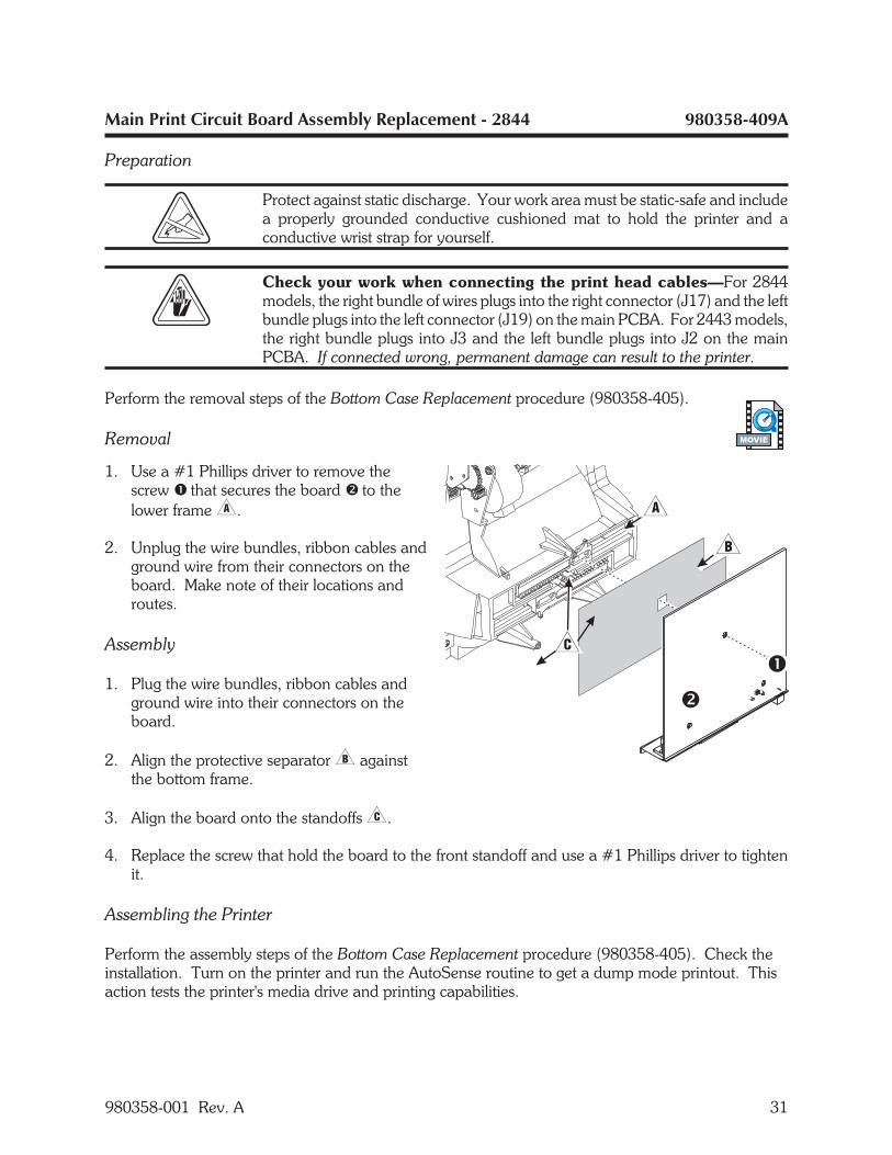
Main Print Circuit Board Assembly Replacement - 2844 980358-409A
Preparation
Protect against static discharge. Your work area must be static-safe and includea properly grounded conductive cushioned mat to hold the printer and aconductive wrist strap for yourself.
Check your work when connecting the print head cables—For 2844models, the right bundle of wires plugs into the right connector (J17) and the leftbundle plugs into the left connector (J19) on the main PCBA. For 2443 models,the right bundle plugs into J3 and the left bundle plugs into J2 on the mainPCBA. If connected wrong, permanent damage can result to the printer.
Perform the removal steps of the Bottom Case Replacement procedure (980358-405).
Removal
1. Use a #1 Phillips driver to remove thescrew � that secures the board � to thelower frame�.
2. Unplug the wire bundles, ribbon cables andground wire from their connectors on theboard. Make note of their locations androutes.
Assembly
1. Plug the wire bundles, ribbon cables andground wire into their connectors on theboard.
2. Align the protective separator� againstthe bottom frame.
3. Align the board onto the standoffs�.
4. Replace the screw that hold the board to the front standoff and use a #1 Phillips driver to tightenit.
Assembling the Printer
Perform the assembly steps of the Bottom Case Replacement procedure (980358-405). Check theinstallation. Turn on the printer and run the AutoSense routine to get a dump mode printout. Thisaction tests the printer's media drive and printing capabilities.
MOVIE
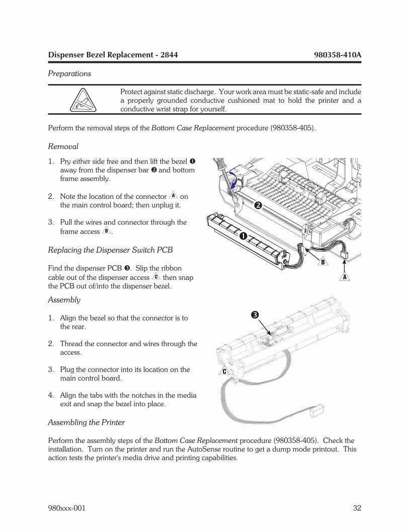
Dispenser Bezel Replacement - 2844 980358-410A
Preparations
Protect against static discharge. Your work area must be static-safe and includea properly grounded conductive cushioned mat to hold the printer and aconductive wrist strap for yourself.
Perform the removal steps of the Bottom Case Replacement procedure (980358-405).
Removal
1. Pry either side free and then lift the bezel �away from the dispenser bar � and bottomframe assembly.
2. Note the location of the connector� onthe main control board; then unplug it.
3. Pull the wires and connector through theframe access�.
Replacing the Dispenser Switch PCB
Find the dispenser PCB �. Slip the ribboncable out of the dispenser access� then snapthe PCB out of/into the dispenser bezel.
Assembly
1. Align the bezel so that the connector is tothe rear.
2. Thread the connector and wires through theaccess.
3. Plug the connector into its location on themain control board.
4. Align the tabs with the notches in the mediaexit and snap the bezel into place.
Assembling the Printer
Perform the assembly steps of the Bottom Case Replacement procedure (980358-405). Check theinstallation. Turn on the printer and run the AutoSense routine to get a dump mode printout. Thisaction tests the printer's media drive and printing capabilities.
980xxx-001 32
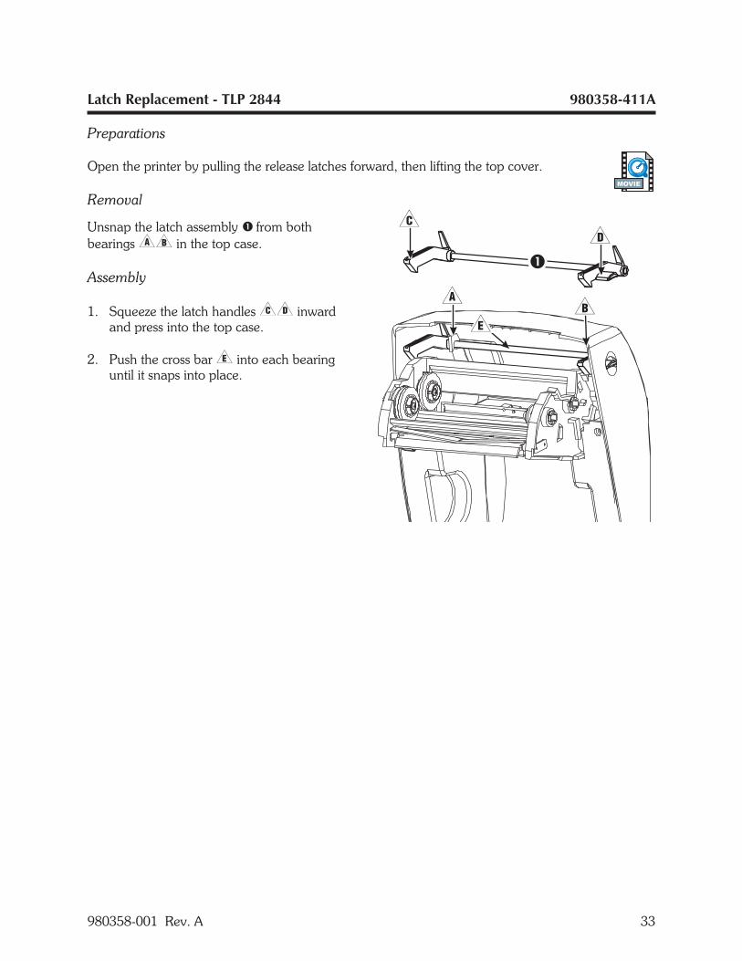
Latch Replacement - TLP 2844 980358-411A
Preparations
Open the printer by pulling the release latches forward, then lifting the top cover.
Removal
Unsnap the latch assembly � from bothbearings�� in the top case.
Assembly
1. Squeeze the latch handles�� inwardand press into the top case.
2. Push the cross bar� into each bearinguntil it snaps into place.
980358-001 Rev. A 33
MOVIE
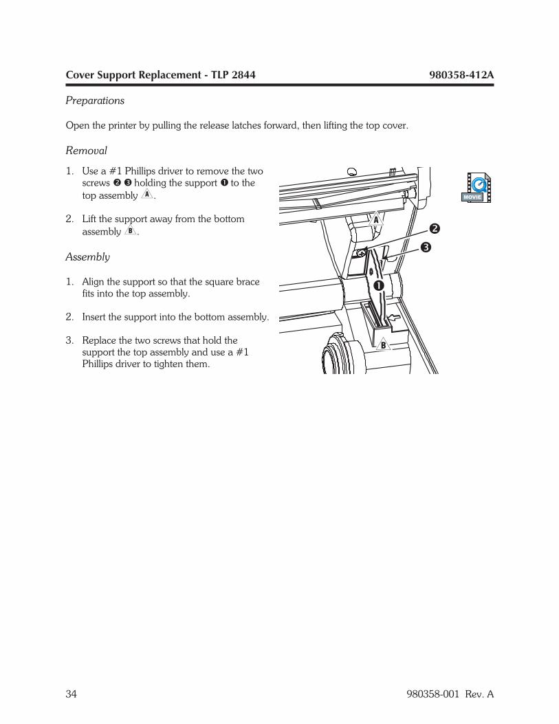
Cover Support Replacement - TLP 2844 980358-412A
Preparations
Open the printer by pulling the release latches forward, then lifting the top cover.
Removal
1. Use a #1 Phillips driver to remove the twoscrews � � holding the support � to thetop assembly�.
2. Lift the support away from the bottomassembly�.
Assembly
1. Align the support so that the square bracefits into the top assembly.
2. Insert the support into the bottom assembly.
3. Replace the two screws that hold thesupport the top assembly and use a #1Phillips driver to tighten them.
34 980358-001 Rev. A
MOVIE
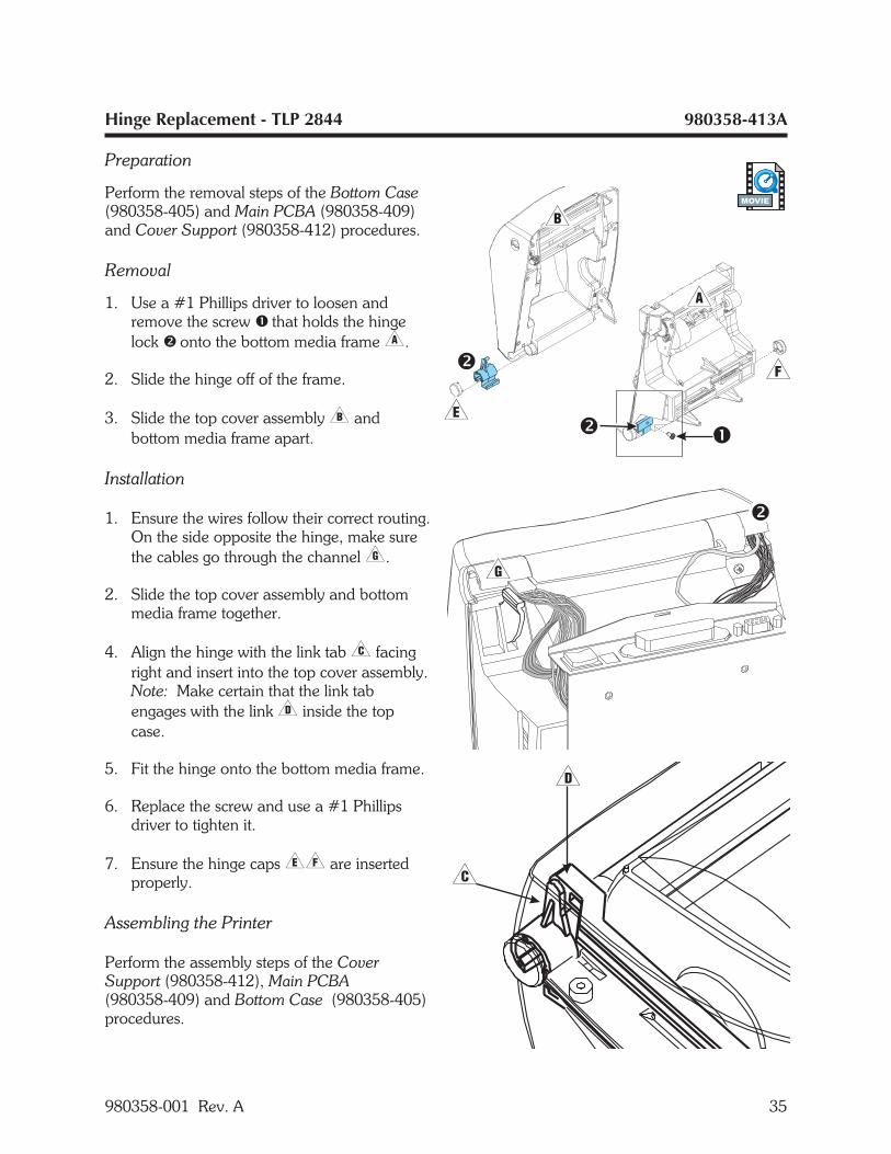
Hinge Replacement - TLP 2844 980358-413A
Preparation
Perform the removal steps of the Bottom Case(980358-405) and Main PCBA (980358-409)and Cover Support (980358-412) procedures.
Removal
1. Use a #1 Phillips driver to loosen andremove the screw � that holds the hingelock � onto the bottom media frame�.
2. Slide the hinge off of the frame.
3. Slide the top cover assembly� andbottom media frame apart.
Installation
1. Ensure the wires follow their correct routing.On the side opposite the hinge, make surethe cables go through the channel�.
2. Slide the top cover assembly and bottommedia frame together.
4. Align the hinge with the link tab� facingright and insert into the top cover assembly.Note: Make certain that the link tabengages with the link� inside the topcase.
5. Fit the hinge onto the bottom media frame.
6. Replace the screw and use a #1 Phillipsdriver to tighten it.
7. Ensure the hinge caps�� are insertedproperly.
Assembling the Printer
Perform the assembly steps of the CoverSupport (980358-412), Main PCBA(980358-409) and Bottom Case (980358-405)procedures.
980358-001 Rev. A 35
MOVIE
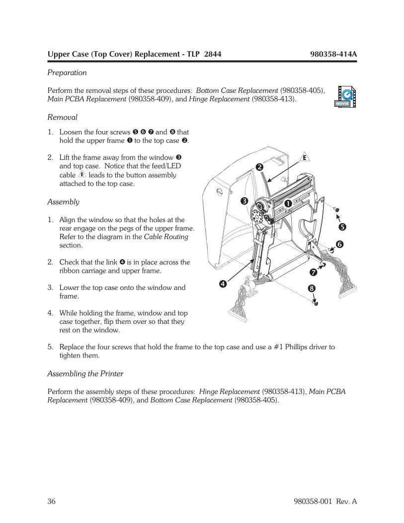
Upper Case (Top Cover) Replacement - TLP 2844 980358-414A
Preparation
Perform the removal steps of these procedures: Bottom Case Replacement (980358-405),Main PCBA Replacement (980358-409), and Hinge Replacement (980358-413).
Removal
1. Loosen the four screws � � � and � thathold the upper frame � to the top case �.
2. Lift the frame away from the window �and top case. Notice that the feed/LEDcable� leads to the button assemblyattached to the top case.
Assembly
1. Align the window so that the holes at therear engage on the pegs of the upper frame.Refer to the diagram in the Cable Routingsection.
2. Check that the link � is in place across theribbon carriage and upper frame.
3. Lower the top case onto the window andframe.
4. While holding the frame, window and topcase together, flip them over so that theyrest on the window.
5. Replace the four screws that hold the frame to the top case and use a #1 Phillips driver totighten them.
Assembling the Printer
Perform the assembly steps of these procedures: Hinge Replacement (980358-413), Main PCBAReplacement (980358-409), and Bottom Case Replacement (980358-405).
36 980358-001 Rev. A
MOVIE
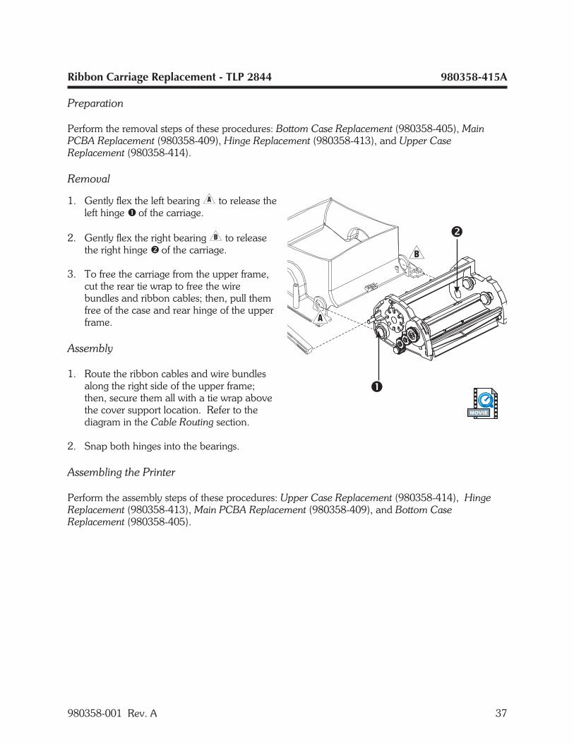
Ribbon Carriage Replacement - TLP 2844 980358-415A
Preparation
Perform the removal steps of these procedures: Bottom Case Replacement (980358-405), MainPCBA Replacement (980358-409), Hinge Replacement (980358-413), and Upper CaseReplacement (980358-414).
Removal
1. Gently flex the left bearing� to release theleft hinge � of the carriage.
2. Gently flex the right bearing� to releasethe right hinge � of the carriage.
3. To free the carriage from the upper frame,cut the rear tie wrap to free the wirebundles and ribbon cables; then, pull themfree of the case and rear hinge of the upperframe.
Assembly
1. Route the ribbon cables and wire bundlesalong the right side of the upper frame;then, secure them all with a tie wrap abovethe cover support location. Refer to thediagram in the Cable Routing section.
2. Snap both hinges into the bearings.
Assembling the Printer
Perform the assembly steps of these procedures: Upper Case Replacement (980358-414), HingeReplacement (980358-413), Main PCBA Replacement (980358-409), and Bottom CaseReplacement (980358-405).
980358-001 Rev. A 37
MOVIE
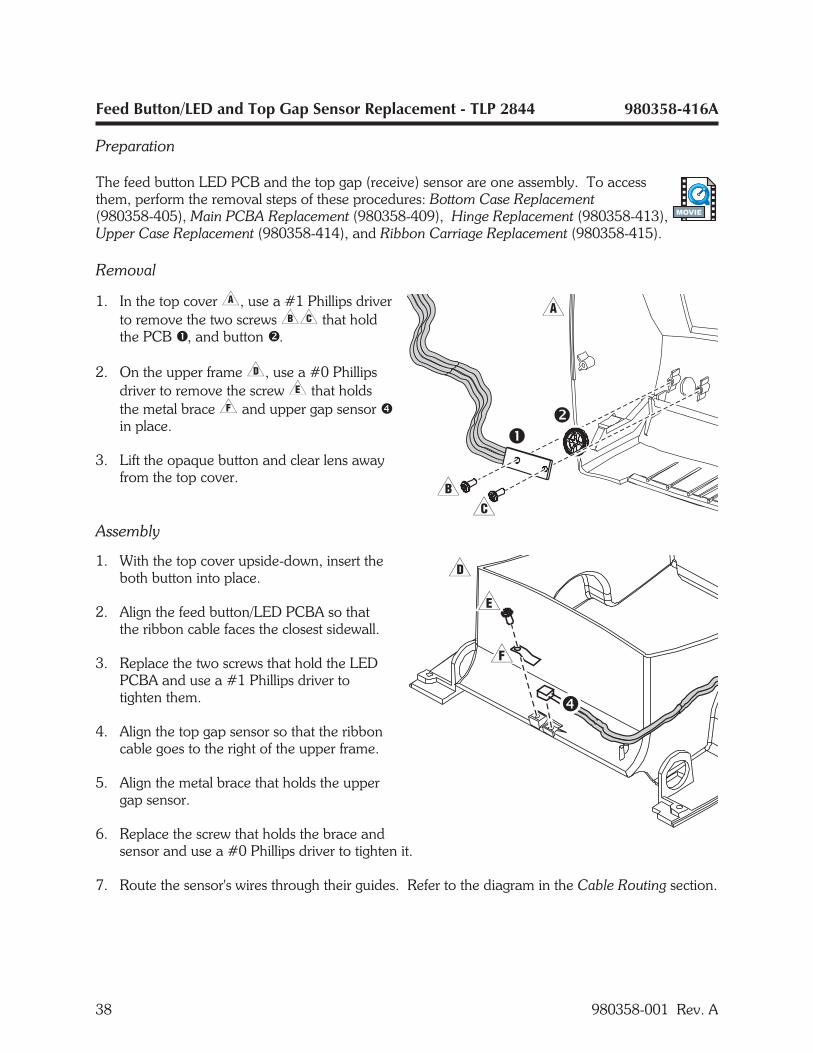
Feed Button/LED and Top Gap Sensor Replacement - TLP 2844 980358-416A
Preparation
The feed button LED PCB and the top gap (receive) sensor are one assembly. To accessthem, perform the removal steps of these procedures: Bottom Case Replacement(980358-405), Main PCBA Replacement (980358-409), Hinge Replacement (980358-413),Upper Case Replacement (980358-414), and Ribbon Carriage Replacement (980358-415).
Removal
1. In the top cover�, use a #1 Phillips driverto remove the two screws�� that holdthe PCB �, and button �.
2. On the upper frame�, use a #0 Phillipsdriver to remove the screw� that holdsthe metal brace� and upper gap sensor �in place.
3. Lift the opaque button and clear lens awayfrom the top cover.
Assembly
1. With the top cover upside-down, insert theboth button into place.
2. Align the feed button/LED PCBA so thatthe ribbon cable faces the closest sidewall.
3. Replace the two screws that hold the LEDPCBA and use a #1 Phillips driver totighten them.
4. Align the top gap sensor so that the ribboncable goes to the right of the upper frame.
5. Align the metal brace that holds the uppergap sensor.
6. Replace the screw that holds the brace andsensor and use a #0 Phillips driver to tighten it.
7. Route the sensor's wires through their guides. Refer to the diagram in the Cable Routing section.
38 980358-001 Rev. A
MOVIE

Feed Button/LED and Top Gap Sensor Replacement (Continued) 980358-416A
Assembling the Printer
Perform the assembly steps of these procedures: Ribbon Carriage Replacement (980358-415),Upper Case Replacement (980358-414), Hinge Replacement (980358-413), Main PCBAReplacement (980358-409), and Bottom Case Replacement (980358-405).
980358-001 Rev. A 39
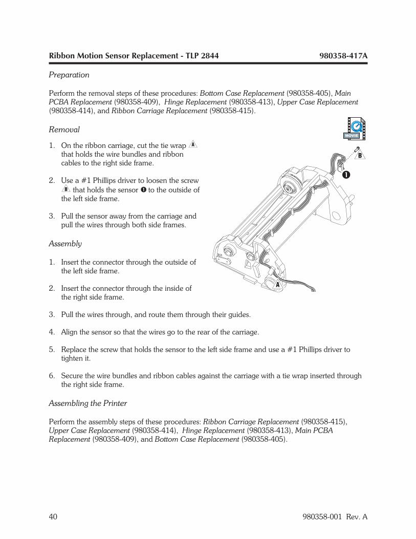
Ribbon Motion Sensor Replacement - TLP 2844 980358-417A
Preparation
Perform the removal steps of these procedures: Bottom Case Replacement (980358-405), MainPCBA Replacement (980358-409), Hinge Replacement (980358-413), Upper Case Replacement(980358-414), and Ribbon Carriage Replacement (980358-415).
Removal
1. On the ribbon carriage, cut the tie wrap�that holds the wire bundles and ribboncables to the right side frame.
2. Use a #1 Phillips driver to loosen the screw� that holds the sensor � to the outside ofthe left side frame.
3. Pull the sensor away from the carriage andpull the wires through both side frames.
Assembly
1. Insert the connector through the outside ofthe left side frame.
2. Insert the connector through the inside ofthe right side frame.
3. Pull the wires through, and route them through their guides.
4. Align the sensor so that the wires go to the rear of the carriage.
5. Replace the screw that holds the sensor to the left side frame and use a #1 Phillips driver totighten it.
6. Secure the wire bundles and ribbon cables against the carriage with a tie wrap inserted throughthe right side frame.
Assembling the Printer
Perform the assembly steps of these procedures: Ribbon Carriage Replacement (980358-415),Upper Case Replacement (980358-414), Hinge Replacement (980358-413), Main PCBAReplacement (980358-409), and Bottom Case Replacement (980358-405).
40 980358-001 Rev. A
MOVIE
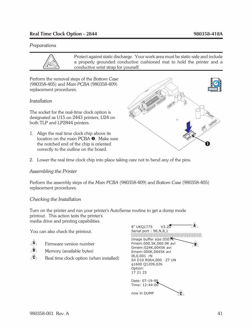
Real Time Clock Option - 2844 980358-418A
Preparations
Protect against static discharge. Your work area must be static-safe and includea properly grounded conductive cushioned mat to hold the printer and aconductive wrist strap for yourself.
Perform the removal steps of the Bottom Case(980358-405) and Main PCBA (980358-409)replacement procedures.
Installation
The socket for the real-time clock option isdesignated as U15 on 2443 printers, U24 onboth TLP and LP2844 printers.
1. Align the real time clock chip above itslocation on the main PCBA �. Make surethe notched end of the chip is orientedcorrectly to the outline on the board.
2. Lower the real time clock chip into place taking care not to bend any of the pins.
Assembling the Printer
Perform the assembly steps of the Main PCBA (980358-409) and Bottom Case (980358-405)replacement procedures.
Checking the Installation
Turn on the printer and run your printer's AutoSense routine to get a dump modeprintout. This action tests the printer'smedia drive and printing capabilities.
980358-001 Rev. A 41
8” UKQ1775 V3.20
Serial port : 96,N,8,1
Image buffer size:0507K
Fmem:000.5K,060.9K avl
Gmem:024K,0045K avl
E
I8,0,001 rN
S4 D10 R064,000 ZT UN
q1600 Q1209,026
Option:
17 21 25
Date: 07-19-99
Time: 12:44:00
now in DUMP
mem:000K,0045K avl
You can also check the printout.
� Firmware version number
� Memory (available bytes)
� Real time clock option (when installed)
MOVIE
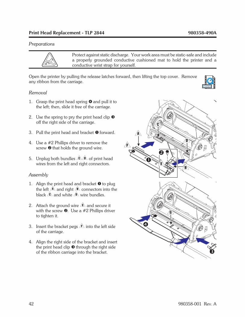
Print Head Replacement - TLP 2844 980358-490A
Preparations
Protect against static discharge. Your work area must be static-safe and includea properly grounded conductive cushioned mat to hold the printer and aconductive wrist strap for yourself.
Open the printer by pulling the release latches forward, then lifting the top cover. Removeany ribbon from the carriage.
Removal
1. Grasp the print head spring � and pull it tothe left; then, slide it free of the carriage.
2. Use the spring to pry the print head clip �off the right side of the carriage.
3. Pull the print head and bracket � forward.
4. Use a #2 Phillips driver to remove thescrew � that holds the ground wire.
5. Unplug both bundles�� of print headwires from the left and right connectors.
Assembly
1. Align the print head and bracket � to plugthe left� and right� connectors into theblack� and white� wire bundles.
2. Attach the ground wire� and secure itwith the screw �. Use a #2 Phillips driverto tighten it.
3. Insert the bracket pegs� into the left sideof the carriage.
4. Align the right side of the bracket and insertthe print head clip � through the right sideof the ribbon carriage into the bracket.
42 980358-001 Rev. A
MOVIE
TLP2844 Print Head Replacement (continued) 980358-490A
5. Slip the left end of the print head spring � into the left side of the ribbon carriage; then slide theright end into the other side. The angle of the "v" fits into the indent on top of the print headbracket�.
6. Clean the print head with the cleaning pen.
Assembling the Printer
Reload media and ribbon. Plug in the power cord, turn on the printer and run the AutoSenseroutine to get a dump mode printout.
980358-001 Rev. A 43

44 980358-001 Rev. A

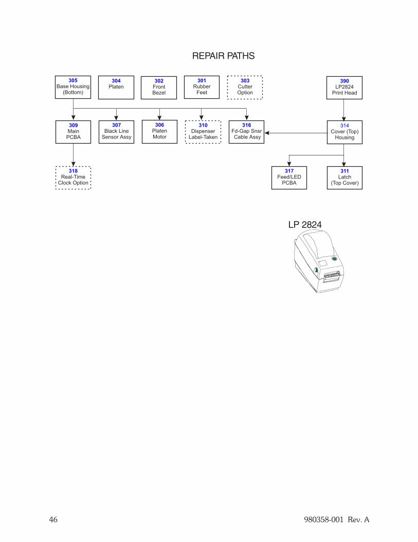
2824 PARTS
The 2824 printers have a two-inch print width. Both the LP and TLP models can print on directthermal media. The TLP model can also print using ribbons and thermal transfer media. Thissection includes procedures that are specific to the 2824 printers.
980358-001 Rev. A 45
46 980358-001 Rev. A
311
Latch(Top Cover)
304
Platen301
RubberFeet
303
CutterOption
316
Fd-Gap SnsrCable Assy
310
DispenserLabel-Taken
307
Black LineSensor Assy
306
PlatenMotor
318
Real-TimeClock Option
302
FrontBezel
305
Base Housing(Bottom)
309
MainPCBA
317
Feed/LEDPCBA
LP 2824
REPAIR PATHS
390
LP2824Print Head
314Cover (Top)
Housing
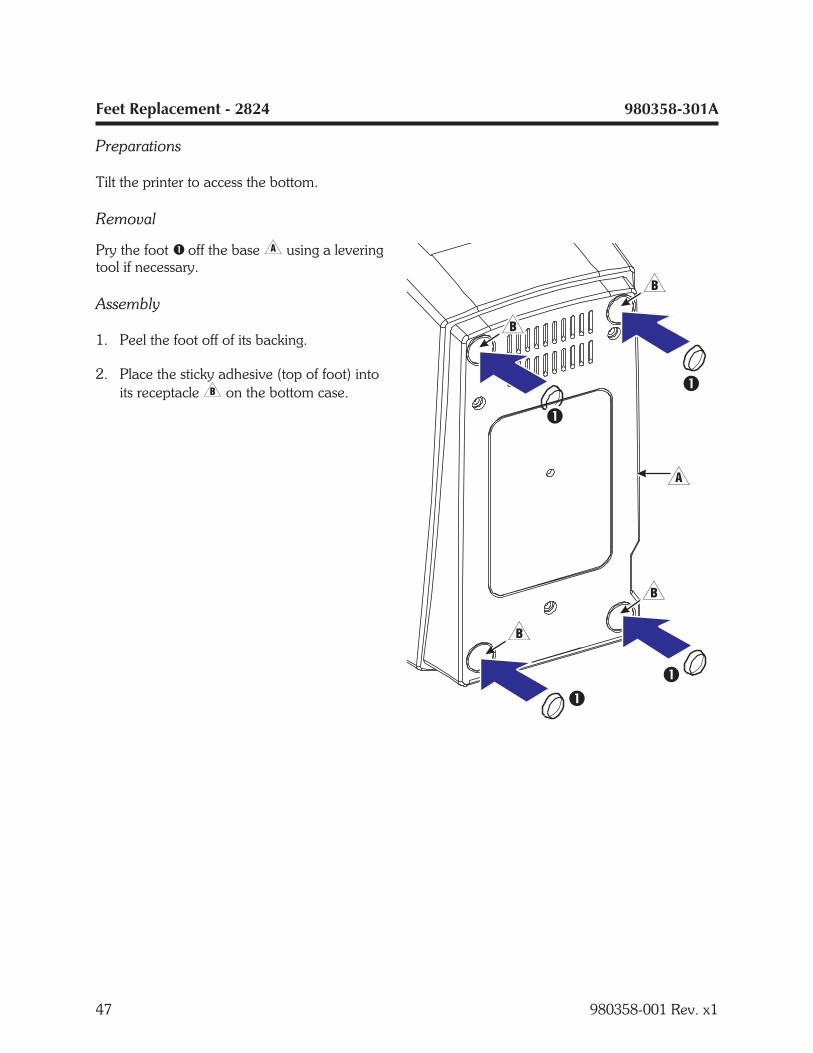
Feet Replacement - 2824 980358-301A
Preparations
Tilt the printer to access the bottom.
Removal
Pry the foot � off the base� using a leveringtool if necessary.
Assembly
1. Peel the foot off of its backing.
2. Place the sticky adhesive (top of foot) intoits receptacle� on the bottom case.
47 980358-001 Rev. x1
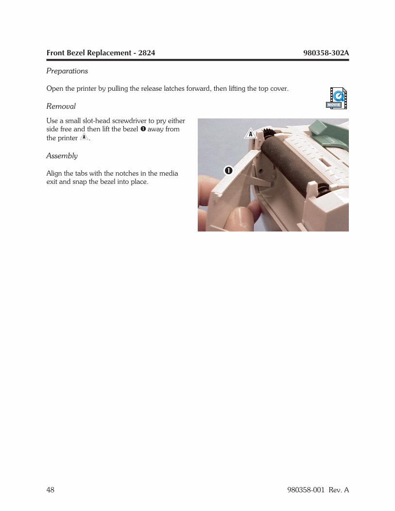
Front Bezel Replacement - 2824 980358-302A
Preparations
Open the printer by pulling the release latches forward, then lifting the top cover.
Removal
Use a small slot-head screwdriver to pry eitherside free and then lift the bezel � away fromthe printer�.
Assembly
Align the tabs with the notches in the mediaexit and snap the bezel into place.
48 980358-001 Rev. A
MOVIE
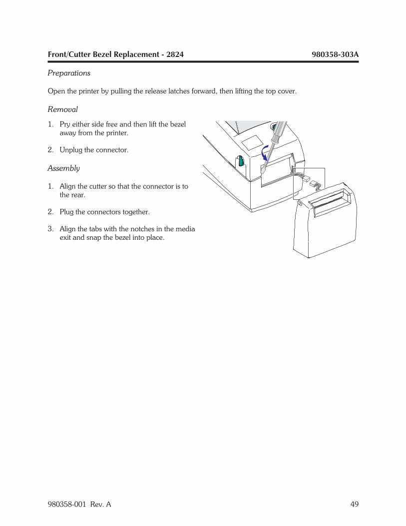
Front/Cutter Bezel Replacement - 2824 980358-303A
Preparations
Open the printer by pulling the release latches forward, then lifting the top cover.
Removal
1. Pry either side free and then lift the bezelaway from the printer.
2. Unplug the connector.
Assembly
1. Align the cutter so that the connector is tothe rear.
2. Plug the connectors together.
3. Align the tabs with the notches in the mediaexit and snap the bezel into place.
980358-001 Rev. A 49
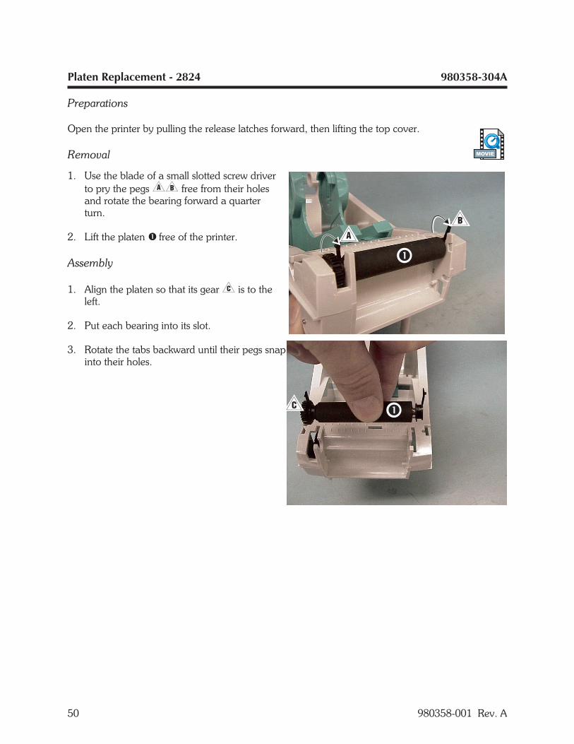
Platen Replacement - 2824 980358-304A
Preparations
Open the printer by pulling the release latches forward, then lifting the top cover.
Removal
1. Use the blade of a small slotted screw driverto pry the pegs�� free from their holesand rotate the bearing forward a quarterturn.
2. Lift the platen � free of the printer.
Assembly
1. Align the platen so that its gear� is to theleft.
2. Put each bearing into its slot.
3. Rotate the tabs backward until their pegs snapinto their holes.
50 980358-001 Rev. A
MOVIE
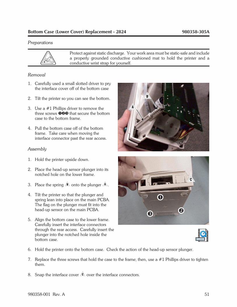
Bottom Case (Lower Cover) Replacement - 2824 980358-305A
Preparations
Protect against static discharge. Your work area must be static-safe and includea properly grounded conductive cushioned mat to hold the printer and aconductive wrist strap for yourself.
Removal
1. Carefully used a small slotted driver to prythe interface cover off of the bottom case
2. Tilt the printer so you can see the bottom.
3. Use a #1 Phillips driver to remove thethree screws ��� that secure the bottomcase to the bottom frame.
4. Pull the bottom case off of the bottomframe. Take care when moving theinterface connector past the rear access.
Assembly
1. Hold the printer upside down.
2. Place the head-up sensor plunger into itsnotched hole on the lower frame.
3. Place the spring� onto the plunger�.
4. Tilt the printer so that the plunger andspring lean into place on the main PCBA.The flag on the plunger must fit into thehead-up sensor on the main PCBA.
5. Align the bottom case to the lower frame.Carefully insert the interface connectorsthrough the rear access. Carefully insert theplunger into the notched hole inside thebottom case.
6. Hold the printer onto the bottom case. Check the action of the head-up sensor plunger.
7. Replace the three screws that hold the case to the frame; then, use a #1 Phillips driver to tightenthem.
8. Snap the interface cover� over the interface connectors.
980358-001 Rev. A 51
MOVIE
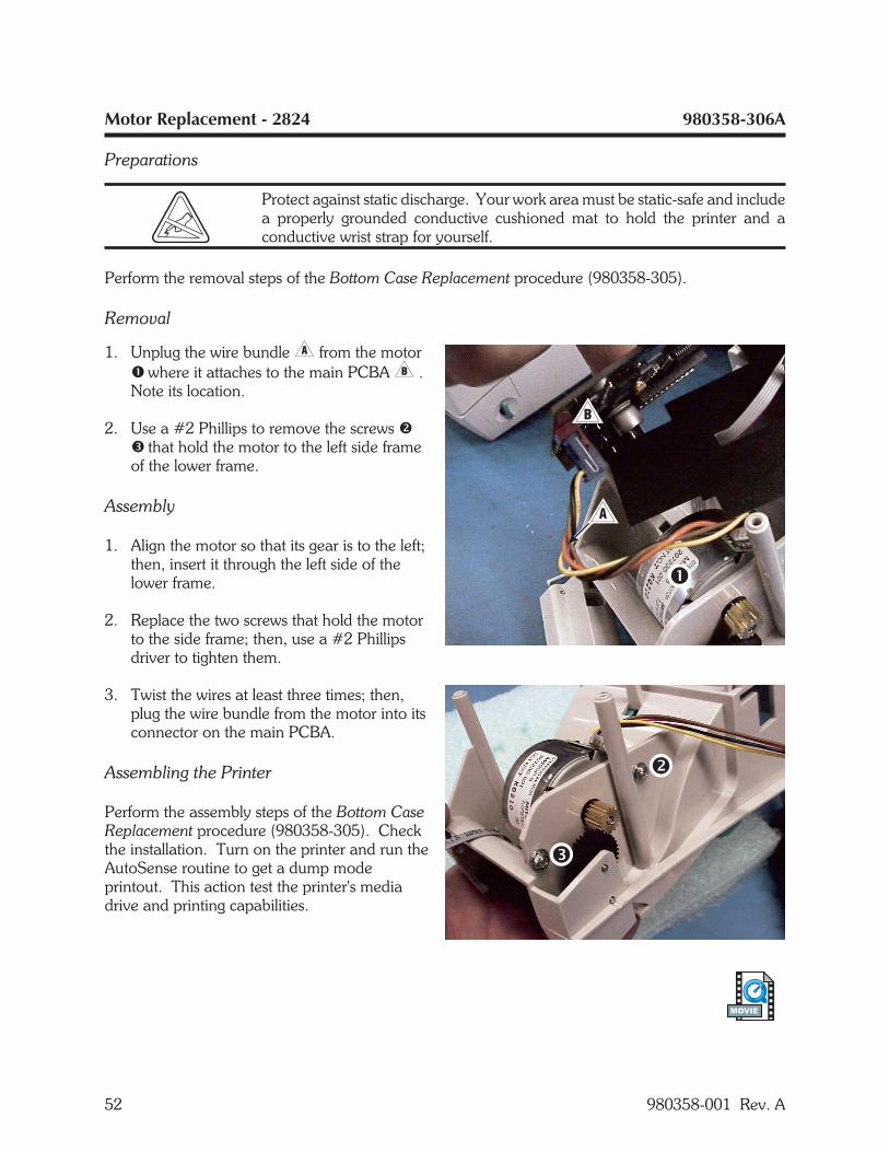
Motor Replacement - 2824 980358-306A
Preparations
Protect against static discharge. Your work area must be static-safe and includea properly grounded conductive cushioned mat to hold the printer and aconductive wrist strap for yourself.
Perform the removal steps of the Bottom Case Replacement procedure (980358-305).
Removal
1. Unplug the wire bundle� from the motor� where it attaches to the main PCBA� .Note its location.
2. Use a #2 Phillips to remove the screws �� that hold the motor to the left side frameof the lower frame.
Assembly
1. Align the motor so that its gear is to the left;then, insert it through the left side of thelower frame.
2. Replace the two screws that hold the motorto the side frame; then, use a #2 Phillipsdriver to tighten them.
3. Twist the wires at least three times; then,plug the wire bundle from the motor into itsconnector on the main PCBA.
Assembling the Printer
Perform the assembly steps of the Bottom CaseReplacement procedure (980358-305). Checkthe installation. Turn on the printer and run theAutoSense routine to get a dump modeprintout. This action test the printer's mediadrive and printing capabilities.
52 980358-001 Rev. A
MOVIE
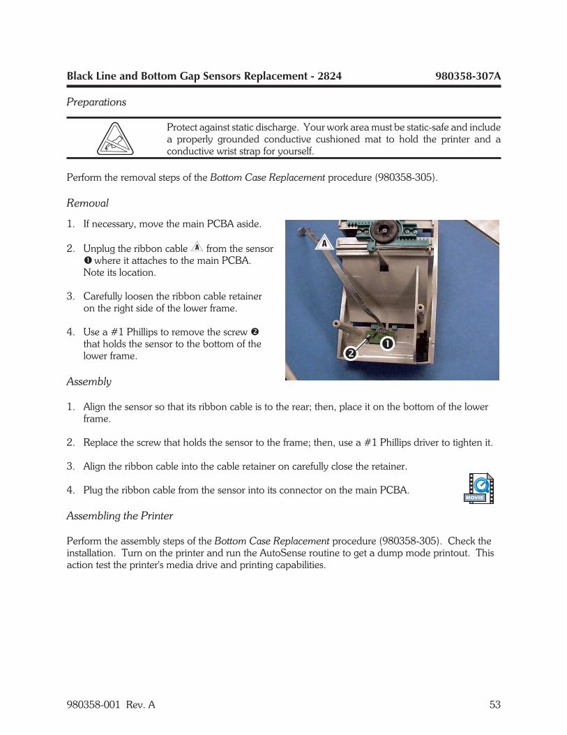
Black Line and Bottom Gap Sensors Replacement - 2824 980358-307A
Preparations
Protect against static discharge. Your work area must be static-safe and includea properly grounded conductive cushioned mat to hold the printer and aconductive wrist strap for yourself.
Perform the removal steps of the Bottom Case Replacement procedure (980358-305).
Removal
1. If necessary, move the main PCBA aside.
2. Unplug the ribbon cable� from the sensor� where it attaches to the main PCBA.Note its location.
3. Carefully loosen the ribbon cable retaineron the right side of the lower frame.
4. Use a #1 Phillips to remove the screw �that holds the sensor to the bottom of thelower frame.
Assembly
1. Align the sensor so that its ribbon cable is to the rear; then, place it on the bottom of the lowerframe.
2. Replace the screw that holds the sensor to the frame; then, use a #1 Phillips driver to tighten it.
3. Align the ribbon cable into the cable retainer on carefully close the retainer.
4. Plug the ribbon cable from the sensor into its connector on the main PCBA.
Assembling the Printer
Perform the assembly steps of the Bottom Case Replacement procedure (980358-305). Check theinstallation. Turn on the printer and run the AutoSense routine to get a dump mode printout. Thisaction test the printer's media drive and printing capabilities.
980358-001 Rev. A 53
MOVIE
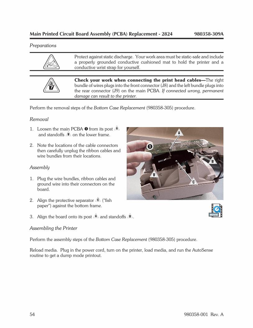
Main Printed Circuit Board Assembly (PCBA) Replacement - 2824 980358-309A
Preparations
Protect against static discharge. Your work area must be static-safe and includea properly grounded conductive cushioned mat to hold the printer and aconductive wrist strap for yourself.
Check your work when connecting the print head cables—The rightbundle of wires plugs into the front connector (J8) and the left bundle plugs intothe rear connector (J9) on the main PCBA. If connected wrong, permanentdamage can result to the printer.
Perform the removal steps of the Bottom Case Replacement (980358-305) procedure.
Removal
1. Loosen the main PCBA � from its post�and standoffs� on the lower frame.
2. Note the locations of the cable connectorsthen carefully unplug the ribbon cables andwire bundles from their locations.
Assembly
1. Plug the wire bundles, ribbon cables andground wire into their connectors on theboard.
2. Align the protective separator� ("fishpaper") against the bottom frame.
3. Align the board onto its post� and standoffs�.
Assembling the Printer
Perform the assembly steps of the Bottom Case Replacement (980358-305) procedure.
Reload media. Plug in the power cord, turn on the printer, load media, and run the AutoSenseroutine to get a dump mode printout.
54 980358-001 Rev. A
MOVIE

Dispenser Bezel Replacement - 2824 980358-310A
Preparations
Protect against static discharge. Your work area must be static-safe and includea properly grounded conductive cushioned mat to hold the printer and aconductive wrist strap for yourself.
Perform the removal steps of the Bottom Case Replacement procedure (980358-305).
Removal
1. Pry either side free and then lift the bezel �away from the dispenser bar � and bottomframe assembly.
2. Note the location of the connector� onthe main control board; then unplug it.
3. Pull the wires and connector through theframe access�.
Assembly
1. Align the bezel so that the connector is tothe rear.
2. Thread the connector and wires through theaccess in the bottom case� and theprotective separator ("fish paper")�.
3. Plug the connector into its location on themain control board.
4. Align the tabs with the notches in the mediaexit and snap the bezel into place.
Assembling the Printer
Perform the assembly steps of the Bottom CaseReplacement procedure (980358-305). Checkthe installation. Turn on the printer and run theAutoSense routine to get a dump modeprintout. This action test the printer's mediadrive and printing capabilities.
980358-001 Rev. A 55
MOVIE
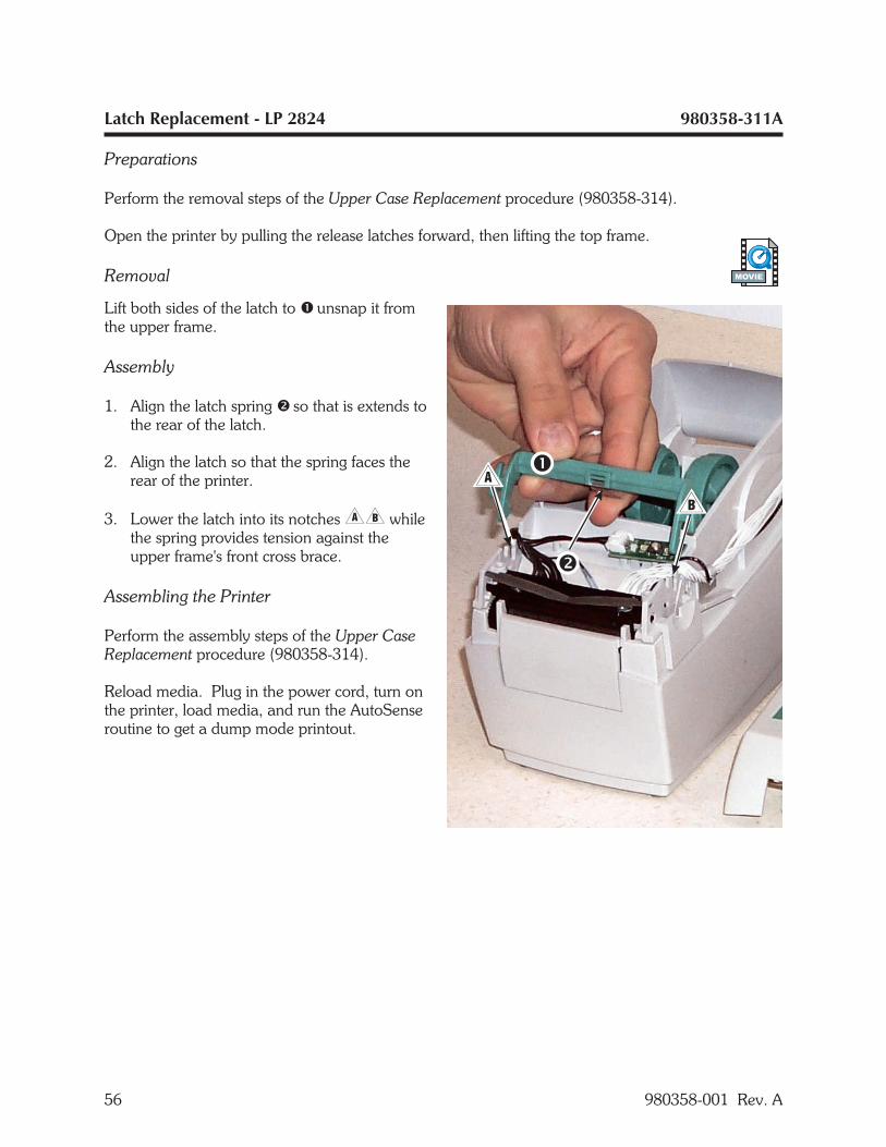
Latch Replacement - LP 2824 980358-311A
Preparations
Perform the removal steps of the Upper Case Replacement procedure (980358-314).
Open the printer by pulling the release latches forward, then lifting the top frame.
Removal
Lift both sides of the latch to � unsnap it fromthe upper frame.
Assembly
1. Align the latch spring � so that is extends tothe rear of the latch.
2. Align the latch so that the spring faces therear of the printer.
3. Lower the latch into its notches�� whilethe spring provides tension against theupper frame's front cross brace.
Assembling the Printer
Perform the assembly steps of the Upper CaseReplacement procedure (980358-314).
Reload media. Plug in the power cord, turn onthe printer, load media, and run the AutoSenseroutine to get a dump mode printout.
56 980358-001 Rev. A
MOVIE
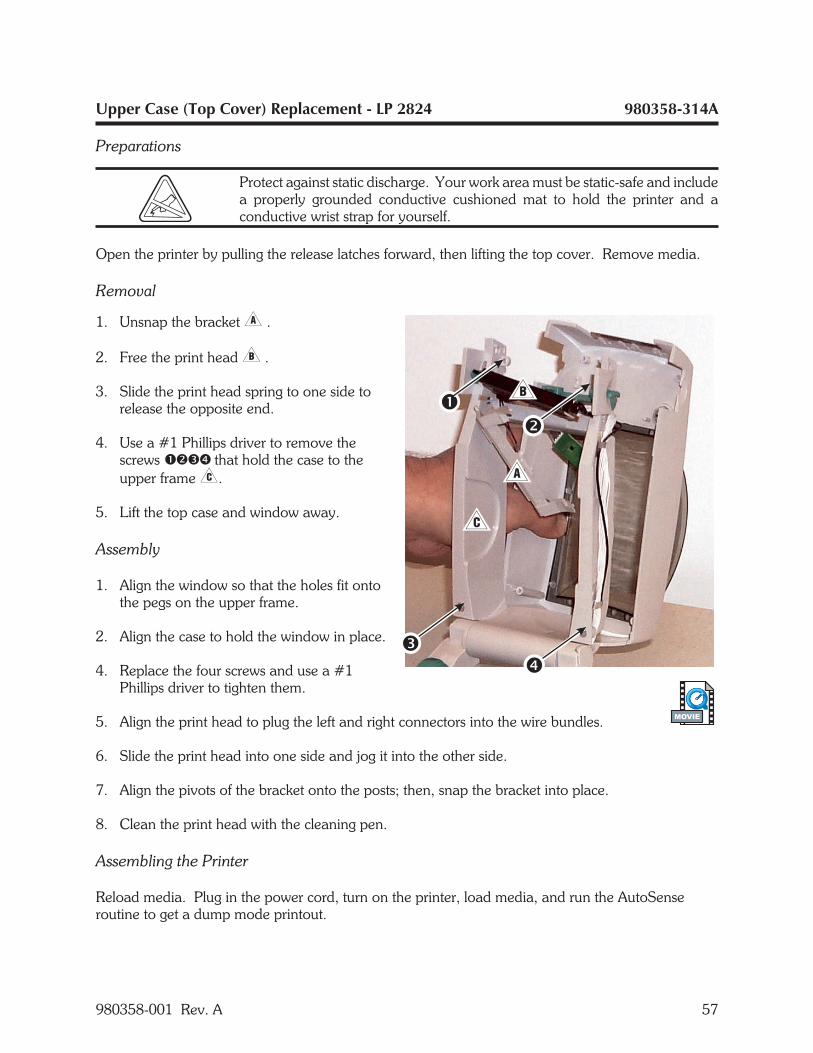
Upper Case (Top Cover) Replacement - LP 2824 980358-314A
Preparations
Protect against static discharge. Your work area must be static-safe and includea properly grounded conductive cushioned mat to hold the printer and aconductive wrist strap for yourself.
Open the printer by pulling the release latches forward, then lifting the top cover. Remove media.
Removal
1. Unsnap the bracket� .
2. Free the print head� .
3. Slide the print head spring to one side torelease the opposite end.
4. Use a #1 Phillips driver to remove thescrews ���� that hold the case to theupper frame�.
5. Lift the top case and window away.
Assembly
1. Align the window so that the holes fit ontothe pegs on the upper frame.
2. Align the case to hold the window in place.
4. Replace the four screws and use a #1Phillips driver to tighten them.
5. Align the print head to plug the left and right connectors into the wire bundles.
6. Slide the print head into one side and jog it into the other side.
7. Align the pivots of the bracket onto the posts; then, snap the bracket into place.
8. Clean the print head with the cleaning pen.
Assembling the Printer
Reload media. Plug in the power cord, turn on the printer, load media, and run the AutoSenseroutine to get a dump mode printout.
980358-001 Rev. A 57
MOVIE
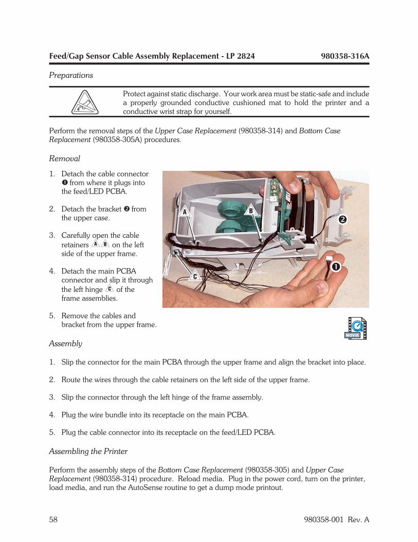
Feed/Gap Sensor Cable Assembly Replacement - LP 2824 980358-316A
Preparations
Protect against static discharge. Your work area must be static-safe and includea properly grounded conductive cushioned mat to hold the printer and aconductive wrist strap for yourself.
Perform the removal steps of the Upper Case Replacement (980358-314) and Bottom CaseReplacement (980358-305A) procedures.
Removal
1. Detach the cable connector� from where it plugs intothe feed/LED PCBA.
2. Detach the bracket � fromthe upper case.
3. Carefully open the cableretainers�� on the leftside of the upper frame.
4. Detach the main PCBAconnector and slip it throughthe left hinge� of theframe assemblies.
5. Remove the cables andbracket from the upper frame.
Assembly
1. Slip the connector for the main PCBA through the upper frame and align the bracket into place.
2. Route the wires through the cable retainers on the left side of the upper frame.
3. Slip the connector through the left hinge of the frame assembly.
4. Plug the wire bundle into its receptacle on the main PCBA.
5. Plug the cable connector into its receptacle on the feed/LED PCBA.
Assembling the Printer
Perform the assembly steps of the Bottom Case Replacement (980358-305) and Upper CaseReplacement (980358-314) procedure. Reload media. Plug in the power cord, turn on the printer,load media, and run the AutoSense routine to get a dump mode printout.
58 980358-001 Rev. A
MOVIE
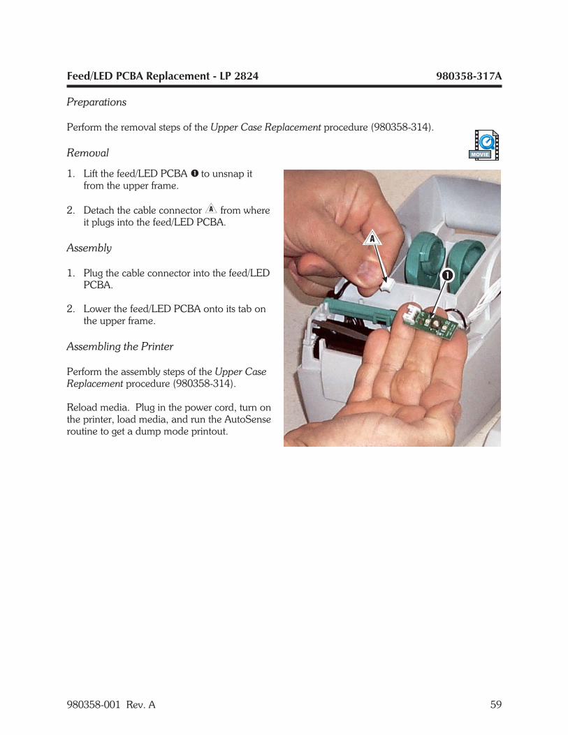
Feed/LED PCBA Replacement - LP 2824 980358-317A
Preparations
Perform the removal steps of the Upper Case Replacement procedure (980358-314).
Removal
1. Lift the feed/LED PCBA � to unsnap itfrom the upper frame.
2. Detach the cable connector� from whereit plugs into the feed/LED PCBA.
Assembly
1. Plug the cable connector into the feed/LEDPCBA.
2. Lower the feed/LED PCBA onto its tab onthe upper frame.
Assembling the Printer
Perform the assembly steps of the Upper CaseReplacement procedure (980358-314).
Reload media. Plug in the power cord, turn onthe printer, load media, and run the AutoSenseroutine to get a dump mode printout.
980358-001 Rev. A 59
MOVIE
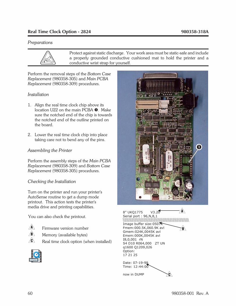
Real Time Clock Option - 2824 980358-318A
Preparations
Protect against static discharge. Your work area must be static-safe and includea properly grounded conductive cushioned mat to hold the printer and aconductive wrist strap for yourself.
Perform the removal steps of the Bottom CaseReplacement (980358-305) and Main PCBAReplacement (980358-309) procedures.
Installation
1. Align the real time clock chip above itslocation U22 on the main PCBA �. Makesure the notched end of the chip is towardsthe notched end of the outline printed onthe board.
2. Lower the real time clock chip into placetaking care not to bend any of the pins.
Assembling the Printer
Perform the assembly steps of the Main PCBAReplacement (980358-309) and Bottom CaseReplacement (980358-305) procedures.
Checking the Installation
Turn on the printer and run your printer'sAutoSense routine to get a dump modeprintout. This action tests the printer'smedia drive and printing capabilities.
60 980358-001 Rev. A
8” UKQ1775 V3.20
Serial port : 96,N,8,1
Image buffer size:0507K
Fmem:000.5K,060.9K avl
Gmem:024K,0045K avl
E
I8,0,001 rN
S4 D10 R064,000 ZT UN
q1600 Q1209,026
Option:
17 21 25
Date: 07-19-99
Time: 12:44:00
now in DUMP
mem:000K,0045K avl
You can also check the printout.
� Firmware version number
� Memory (available bytes)
� Real time clock option (when installed)
MOVIE
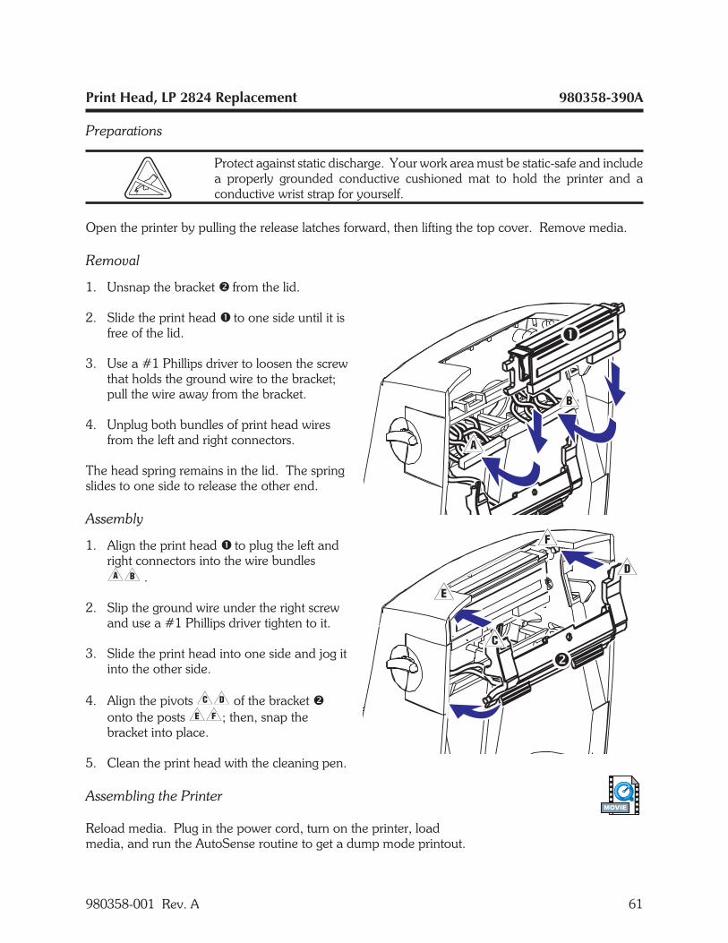
Print Head, LP 2824 Replacement 980358-390A
Preparations
Protect against static discharge. Your work area must be static-safe and includea properly grounded conductive cushioned mat to hold the printer and aconductive wrist strap for yourself.
Open the printer by pulling the release latches forward, then lifting the top cover. Remove media.
Removal
1. Unsnap the bracket � from the lid.
2. Slide the print head � to one side until it isfree of the lid.
3. Use a #1 Phillips driver to loosen the screwthat holds the ground wire to the bracket;pull the wire away from the bracket.
4. Unplug both bundles of print head wiresfrom the left and right connectors.
The head spring remains in the lid. The springslides to one side to release the other end.
Assembly
1. Align the print head � to plug the left andright connectors into the wire bundles�� .
2. Slip the ground wire under the right screwand use a #1 Phillips driver tighten to it.
3. Slide the print head into one side and jog itinto the other side.
4. Align the pivots�� of the bracket �onto the posts��; then, snap thebracket into place.
5. Clean the print head with the cleaning pen.
Assembling the Printer
Reload media. Plug in the power cord, turn on the printer, loadmedia, and run the AutoSense routine to get a dump mode printout.
980358-001 Rev. A 61
MOVIE

62 980358-001 Rev. A

CABLE ROUTING
The following simplified charts show routing for the printer's electronic components.
980358-001 Rev. A 63
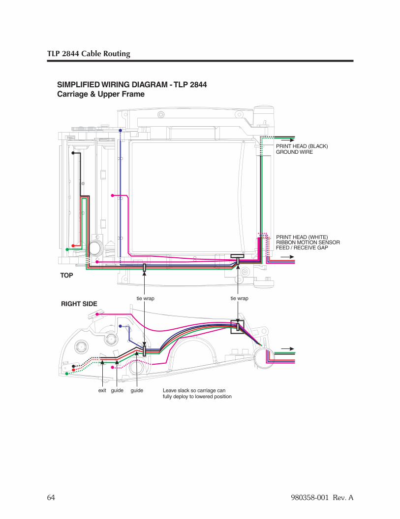
TLP 2844 Cable Routing
64 980358-001 Rev. A
tie wrap tie wrap
PRINT HEAD (WHITE)
GROUND WIRE
RIBBON MOTION SENSOR
PRINT HEAD (BLACK)
RIGHT SIDE
TOP
SIMPLIFIED WIRING DIAGRAM - TLP 2844Carriage & Upper Frame
FEED / RECEIVE GAP
exit guide guide Leave slack so carriage canfully deploy to lowered position
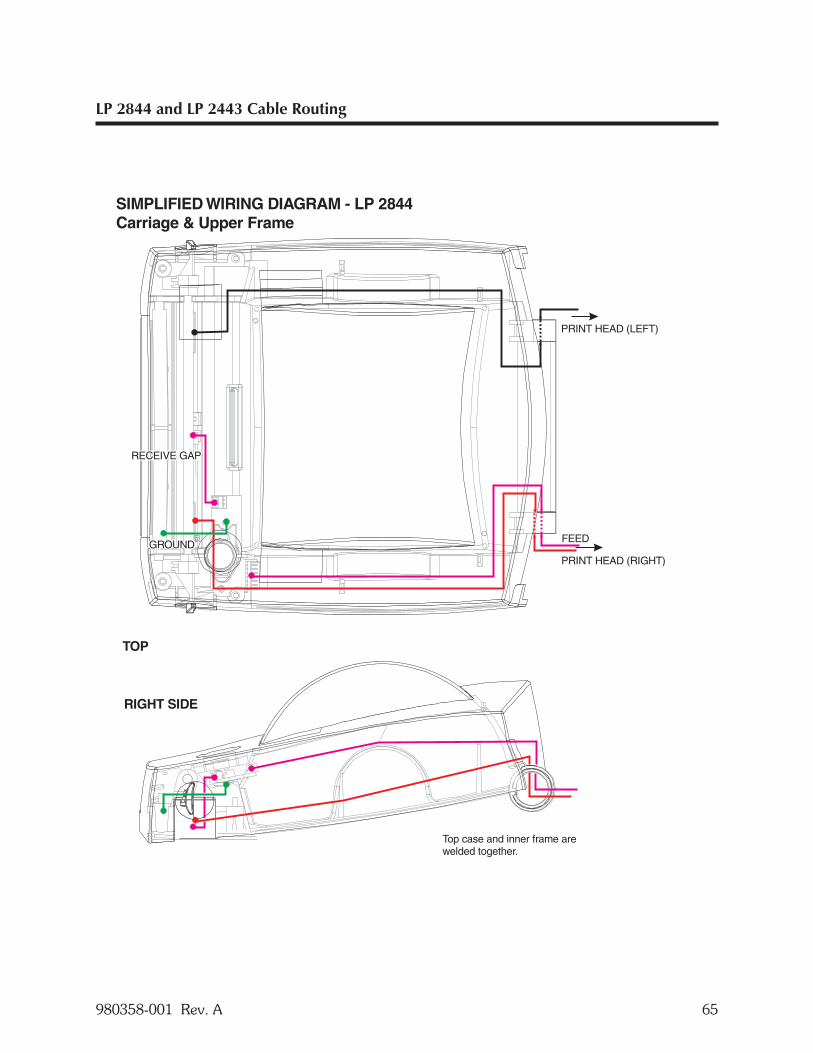
LP 2844 and LP 2443 Cable Routing
980358-001 Rev. A 65
PRINT HEAD (RIGHT)
PRINT HEAD (LEFT)
RIGHT SIDE
TOP
SIMPLIFIED WIRING DIAGRAM - LP 2844Carriage & Upper Frame
FEED
Top case and inner frame arewelded together.
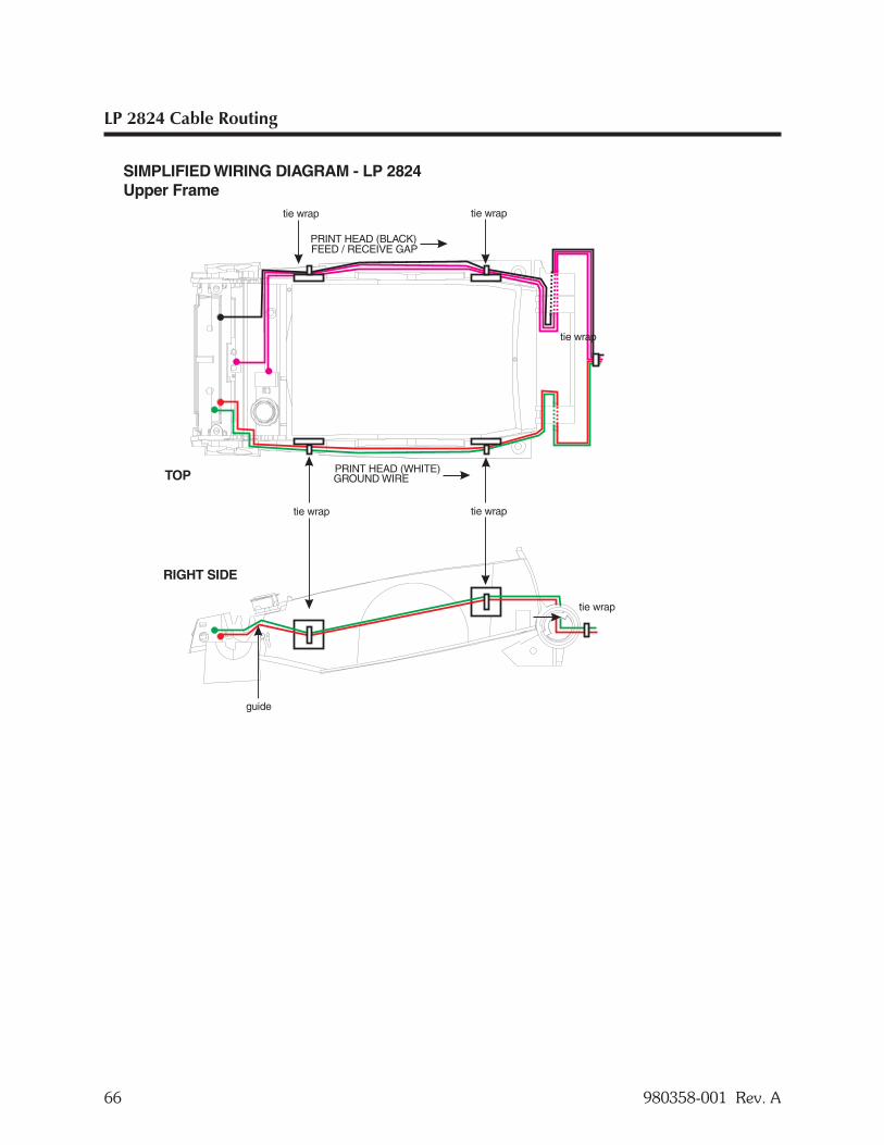
LP 2824 Cable Routing
66 980358-001 Rev. A
SIMPLIFIED WIRING DIAGRAM - LP 2824Upper Frame
RIGHT SIDE
TOP
tie wrap tie wrap
tie wrap tie wrap
tie wrap
guide
PRINT HEAD (WHITE)GROUND WIRE
PRINT HEAD (BLACK)FEED / RECEIVE GAP
tie wrap

980358-001 Rev. A 67

980358- 001 A