Embed Size (px)
Citation preview
1© 2015 The MathWorks, Inc.
Designing MIMO-OFDM
Wireless Communication Systems
Dr. Amod AnandkumarSenior Application Engineer
Signal Processing and Communications

2
Outline
Designing MIMO-OFDM baseband algorithms
Modelling RF frontend for system-level design
Working with SDR and live radio signals

3
Outline
Designing MIMO-OFDM baseband algorithms
Modelling RF frontend for system-level design
Working with SDR and live radio signals
4
Why look at MIMO-OFDM systems?
and many more…

5
Need to design/model
• Advanced baseband algorithms
• Channels with multipath and fading
• Non-linearity and impairments of RF front-end
• Antenna arrays
• Various types of antennas
Challenges in designing MIMO-OFDM systems

6
Demo – Transmitting digital video in a multi-
actor scenario
7
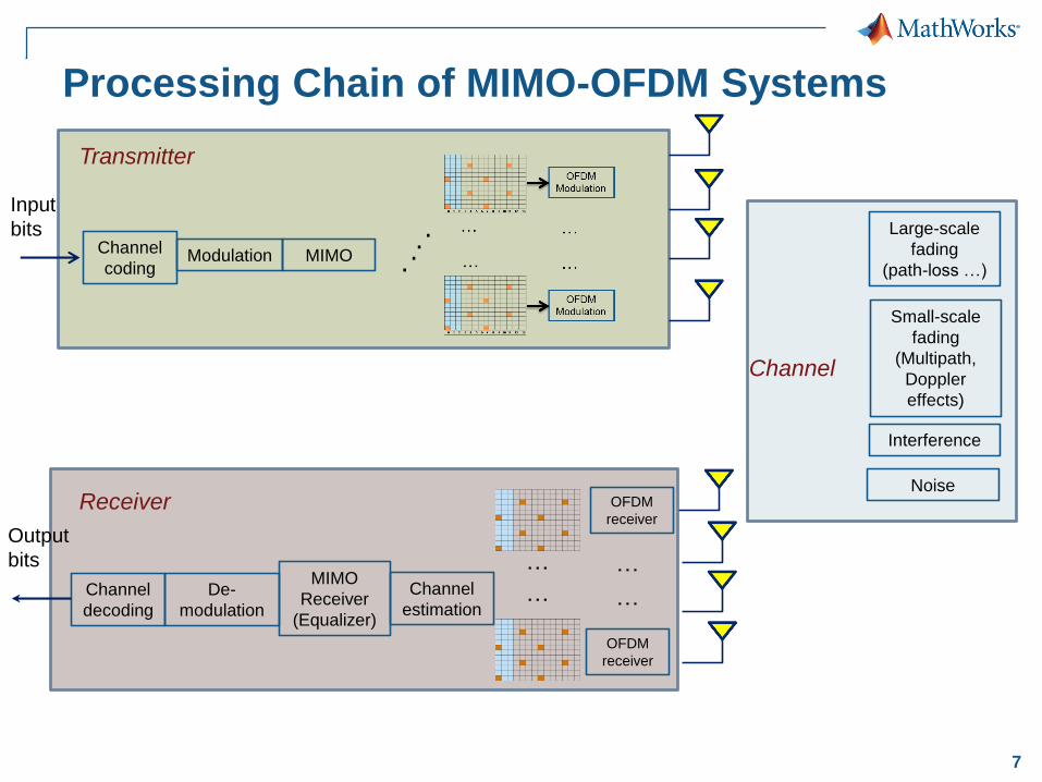
Processing Chain of MIMO-OFDM Systems
Input
bits
ModulationChannel
codingMIMO ..
..
Transmitter
Channel
Large-scale
fading
(path-loss …)
Small-scale
fading
(Multipath,
Doppler
effects)
Interference
NoiseReceiver
Channel
decoding
De-
modulation
MIMO
Receiver
(Equalizer)
Channel
estimation
OFDM
receiver
OFDM
receiver
…
…
…
…
Output
bits
8
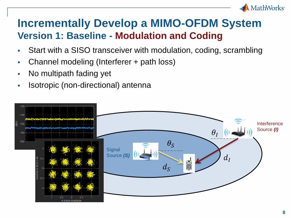
Incrementally Develop a MIMO-OFDM SystemVersion 1: Baseline - Modulation and Coding
Start with a SISO transceiver with modulation, coding, scrambling
Channel modeling (Interferer + path loss)
No multipath fading yet
Isotropic (non-directional) antenna
Signal
Source (S)
Interference
Source (I)
𝜃𝑆
𝜃𝐼
𝑑𝑆
𝑑𝐼
9
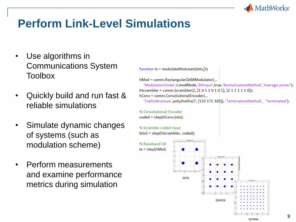
Perform Link-Level Simulations
• Use algorithms in
Communications System
Toolbox
• Quickly build and run fast &
reliable simulations
• Simulate dynamic changes
of systems (such as
modulation scheme)
• Perform measurements
and examine performance
metrics during simulation

10
Version 2: Model OFDM link with Pilot Symbols
• OFDM modulator and
demodulator from
Communications System
Toolbox
• Gold or PN Sequence
generators to generate
pilots (reference signals)
• System objects make
exploring with system
parameters easier
• Explore a wide range of
center frequencies and
bandwidths
11
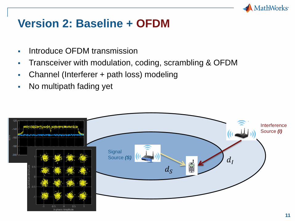
Version 2: Baseline + OFDM
Introduce OFDM transmission
Transceiver with modulation, coding, scrambling & OFDM
Channel (Interferer + path loss) modeling
No multipath fading yet
Signal
Source (S)
Interference
Source (I)
𝑑𝑆
𝑑𝐼
12
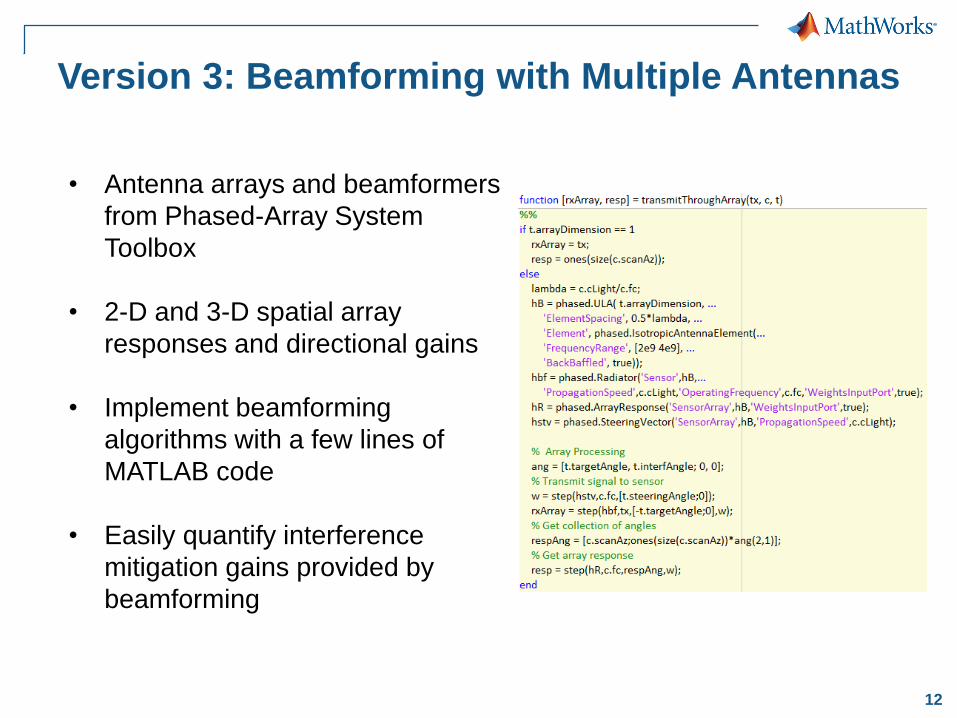
Version 3: Beamforming with Multiple Antennas
• Antenna arrays and beamformers
from Phased-Array System
Toolbox
• 2-D and 3-D spatial array
responses and directional gains
• Implement beamforming
algorithms with a few lines of
MATLAB code
• Easily quantify interference
mitigation gains provided by
beamforming
13
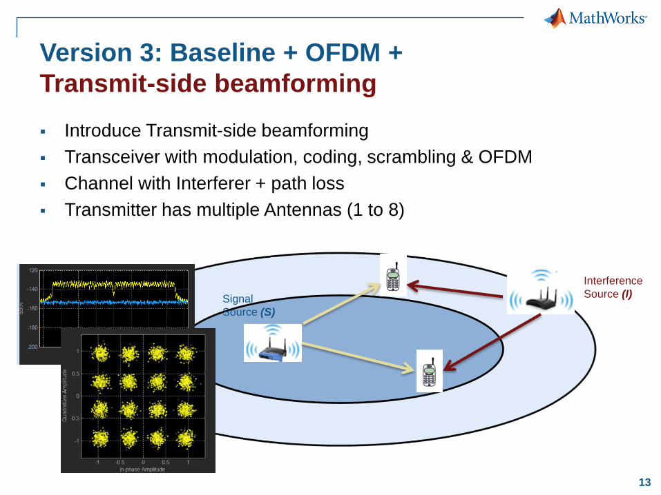
Version 3: Baseline + OFDM +
Transmit-side beamforming
Introduce Transmit-side beamforming
Transceiver with modulation, coding, scrambling & OFDM
Channel with Interferer + path loss
Transmitter has multiple Antennas (1 to 8)
Signal
Source (S)
Interference
Source (I)
14
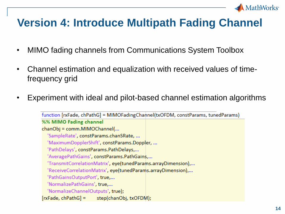
Version 4: Introduce Multipath Fading Channel
• MIMO fading channels from Communications System Toolbox
• Channel estimation and equalization with received values of time-
frequency grid
• Experiment with ideal and pilot-based channel estimation algorithms

15
Final Version: Baseline + OFDM +
Transmit-side beamforming + Multipath fading
Transmit-side beamforming with Multipath fading
Transceiver with modulation, coding, scrambling & OFDM
Channel with Interferer + path loss + multipath propagation
Transmitter has multiple Antennas (1 to 8)
Signal
Source (S)
Interference
Source (I)
16
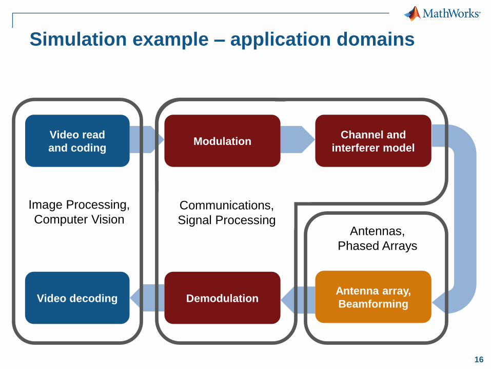
Simulation example – application domains
Video read
and coding
Video decoding Demodulation
Channel and
interferer model
Antenna array,
Beamforming
Image Processing,
Computer VisionCommunications,
Signal ProcessingAntennas,
Phased Arrays
Modulation
17
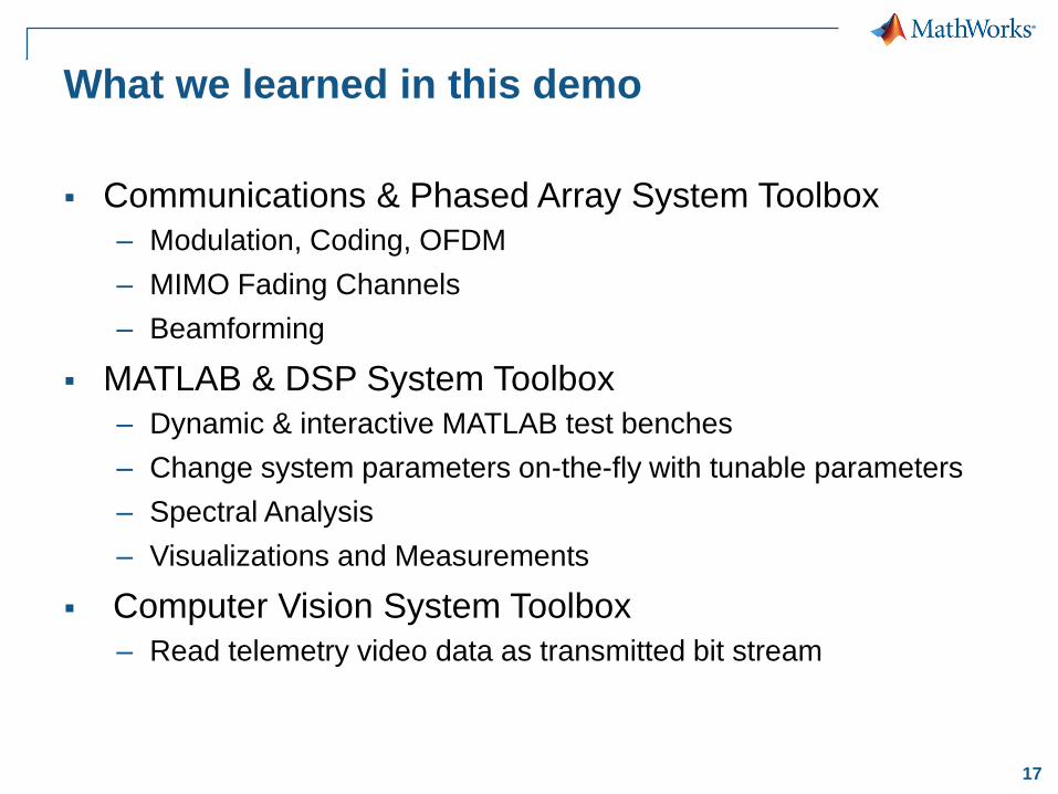
Communications & Phased Array System Toolbox
– Modulation, Coding, OFDM
– MIMO Fading Channels
– Beamforming
MATLAB & DSP System Toolbox
– Dynamic & interactive MATLAB test benches
– Change system parameters on-the-fly with tunable parameters
– Spectral Analysis
– Visualizations and Measurements
Computer Vision System Toolbox
– Read telemetry video data as transmitted bit stream
What we learned in this demo
18
Outline
Designing MIMO-OFDM baseband algorithms
Modelling RF frontend for system-level design
Working with SDR and live radio signals
19
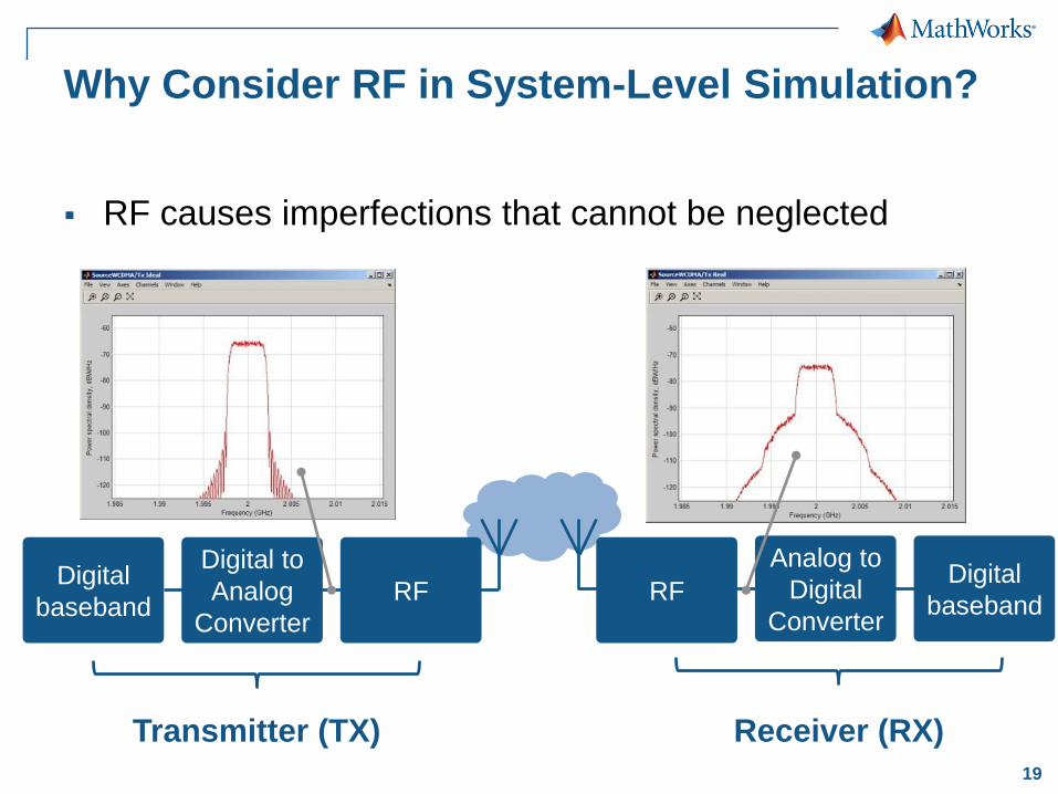
Why Consider RF in System-Level Simulation?
RF causes imperfections that cannot be neglected
Digital
baseband
Digital to
Analog
Converter
RF Digital
baseband
Analog to
Digital
ConverterRF
Transmitter (TX) Receiver (RX)
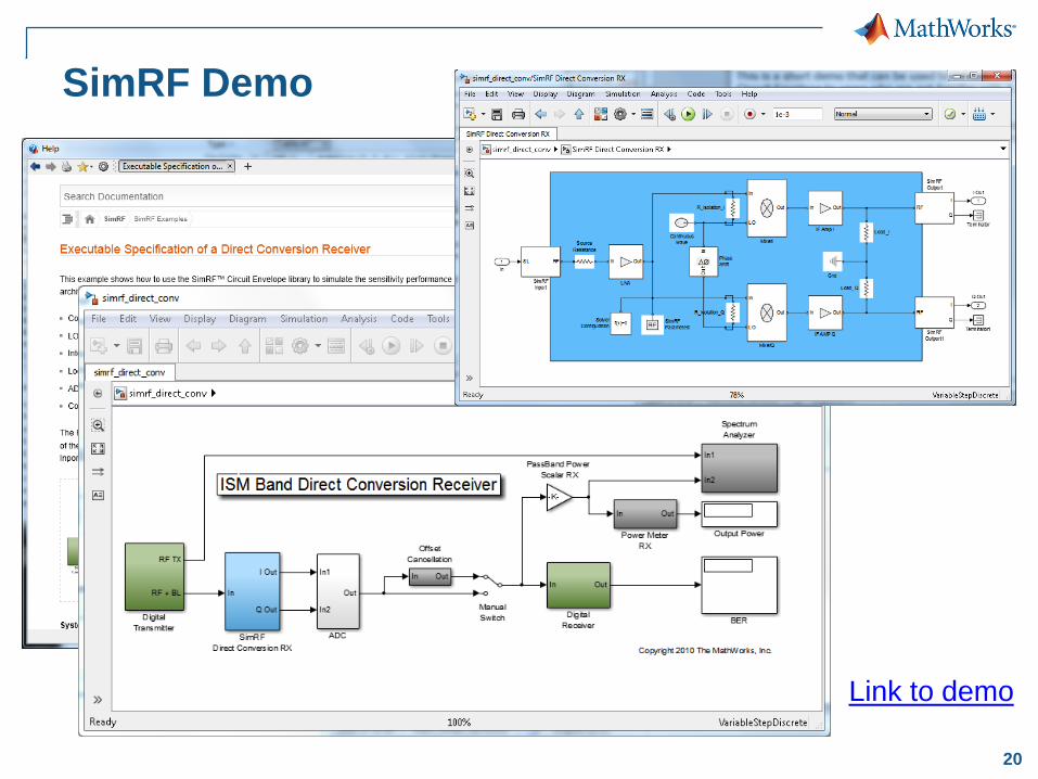
20
SimRF Demo
Link to demo
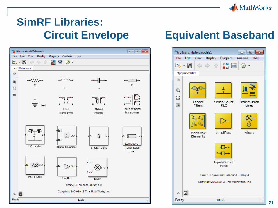
21
SimRF Libraries:
Circuit Envelope Equivalent Baseband
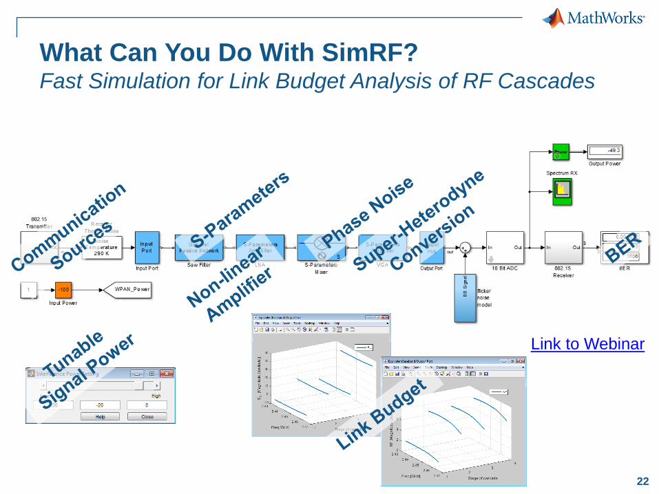
22
What Can You Do With SimRF?Fast Simulation for Link Budget Analysis of RF Cascades
Link to Webinar
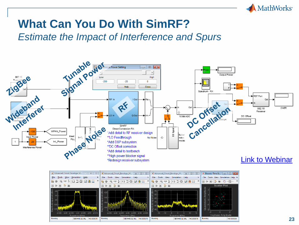
23
What Can You Do With SimRF?Estimate the Impact of Interference and Spurs
Link to Webinar
24
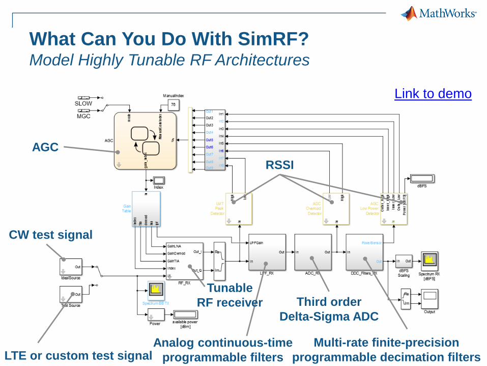
CW test signal
LTE or custom test signalMulti-rate finite-precision
programmable decimation filters
Analog continuous-time
programmable filters
Tunable
RF receiver
What Can You Do With SimRF?Model Highly Tunable RF Architectures
Third order
Delta-Sigma ADC
RSSI
AGC
Link to demo
25
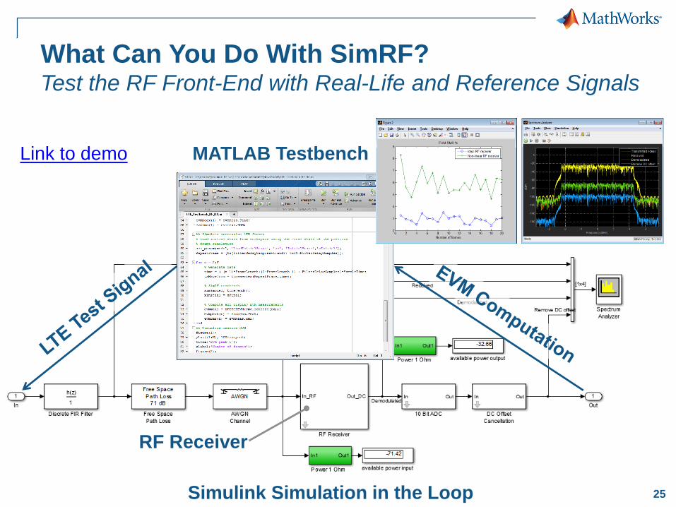
What Can You Do With SimRF?Test the RF Front-End with Real-Life and Reference Signals
MATLAB Testbench
RF Receiver
Simulink Simulation in the Loop
Link to demo
26
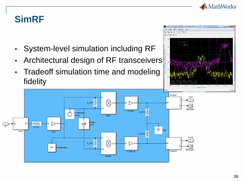
SimRF
System-level simulation including RF
Architectural design of RF transceivers
Tradeoff simulation time and modeling
fidelity
27
Outline
Designing MIMO-OFDM baseband algorithms
Modelling RF frontend for system-level design
Working with SDR and live radio signals
28
Test Your Radio with Over-the-air Communication
Transmit and receive radio signals over the air
Transmit and receive waveforms
Configure hardware parameters
– centre frequency, sampling rate and more
Analyze acquired I/Q baseband signal with configurable
measurement tools
Verify and validate your designs based on live radio
signals
29
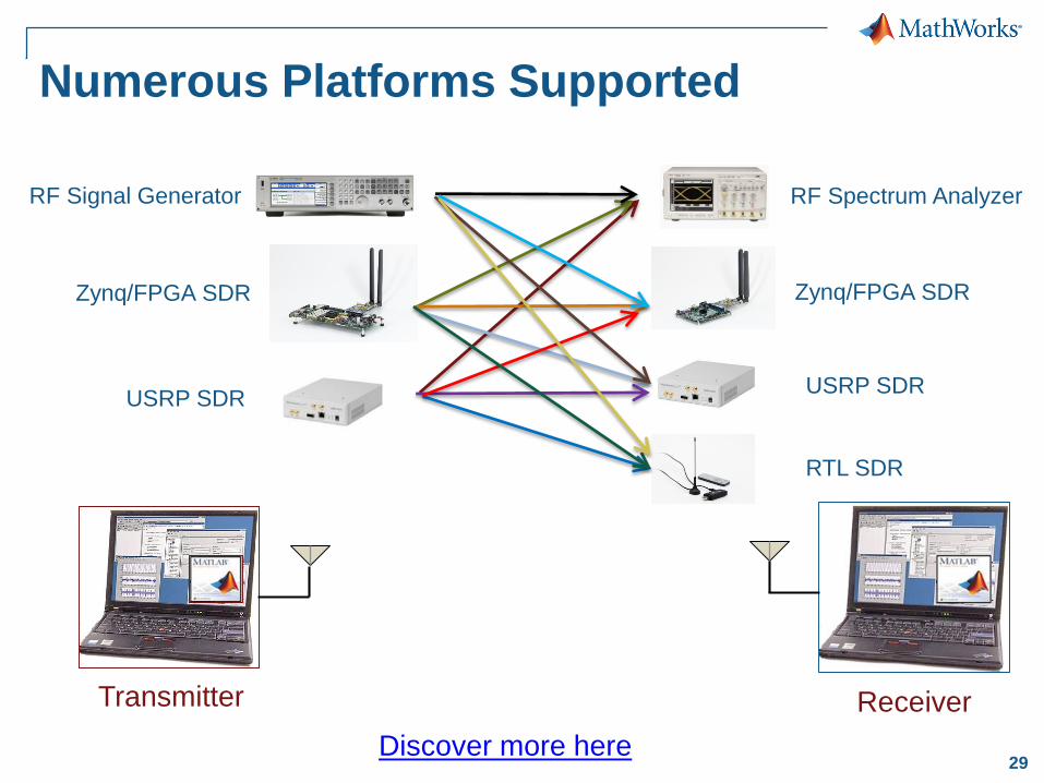
Numerous Platforms Supported
RF Signal Generator
Zynq/FPGA SDR
USRP SDR
RF Spectrum Analyzer
Zynq/FPGA SDR
USRP SDR
RTL SDR
Transmitter Receiver
Discover more here
30
Summary
Designing MIMO-OFDM baseband algorithms
Modelling RF frontend for system-level design
Working with SDR and live radio signals

31
Channel fading, interference, noise
Antenna, Antenna arrays type of element, # elements, configuration, position, impedance, pattern
Model & Simulate From Bits to Antenna (and Back)
Antenna Toolbox
Phased Array System Toolbox
RF Frontendfrequency dependency, non-linearity, noise, mismatches
~~ ~LNA
PA
~~ ~LO1LO2
~~ ~
DSP
Baseband Tx & Rx Algorithms
LTE System Toolbox
Communications System Toolbox
DSP System Toolbox
SimRF
RF Toolbox
LTE System Toolbox
Communications System Toolbox
SDR Support Packages
Instrument Control Toolbox
32
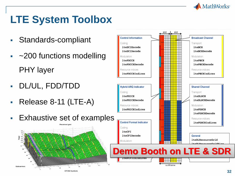
LTE System Toolbox
Standards-compliant
~200 functions modelling
PHY layer
DL/UL, FDD/TDD
Release 8-11 (LTE-A)
Exhaustive set of examples
Demo Booth on LTE & SDR
33
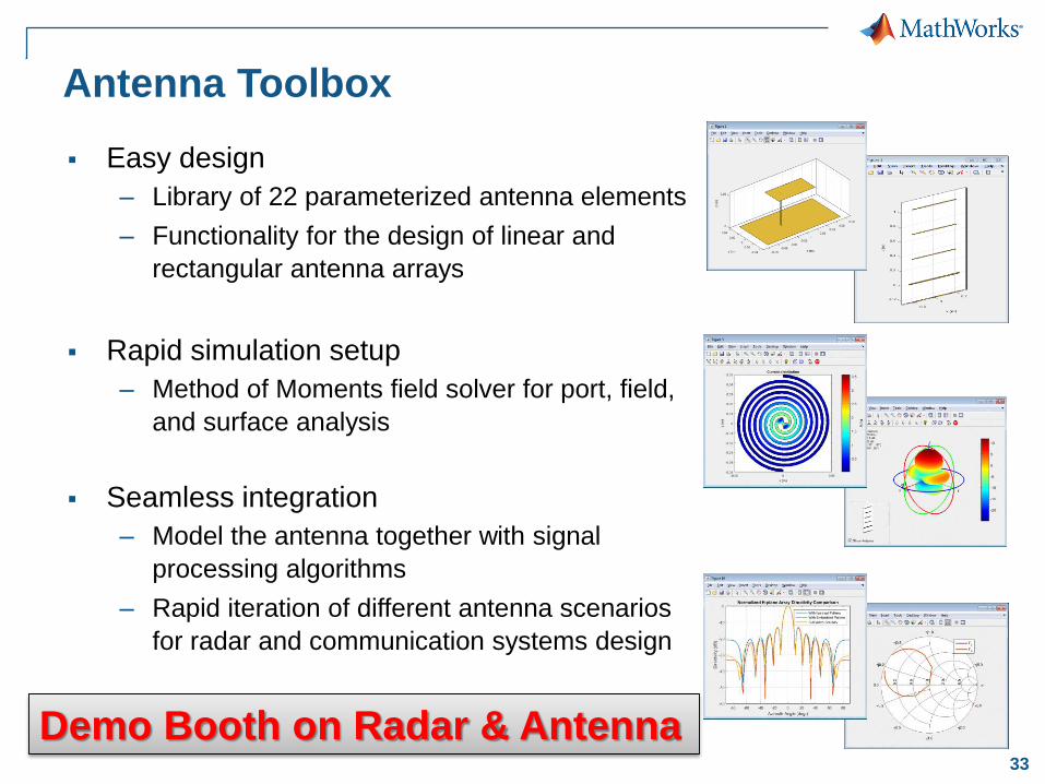
Antenna Toolbox
Easy design
– Library of 22 parameterized antenna elements
– Functionality for the design of linear and
rectangular antenna arrays
Rapid simulation setup
– Method of Moments field solver for port, field,
and surface analysis
Seamless integration
– Model the antenna together with signal
processing algorithms
– Rapid iteration of different antenna scenarios
for radar and communication systems design
Demo Booth on Radar & Antenna

34
Use Parallel Computing for Fast Simulation
User’s Desktop
Parallel Computing Toolbox
Multiple cores
MATLAB Distributed
Computing Server
Compute Cluster
GPU
Link to Demo

35
ChallengeEnsure rapid and reliable transmission of satellite imagery
data from space to ground
SolutionUse Simulink to model the entire RF and digital
communications system and perform simulations to calculate
BER and verify link performance
Results Simulation speed increased by 10x
Distortion effects included in simulation
Data rate increased by 50%
DigitalGlobe Simulates Complete Satellite-to-
Ground Communications Systems
Rendering of the
WorldView-3 satellite.
Link to user story
“We needed to know if our
communications system would
support a 50% increase in data
rate. By modeling and simulating
the antenna, transmitter, and
receiver designs in Simulink, we
got a direct answer: Yes. We had
confidence in this answer
because the simulations showed
us how the system performed.”
Skip Cubbedge
DigitalGlobe
36
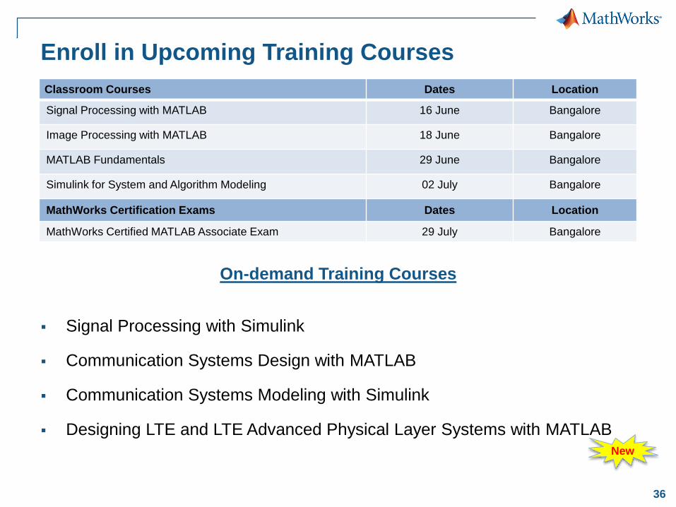
Enroll in Upcoming Training Courses
Signal Processing with Simulink
Communication Systems Design with MATLAB
Communication Systems Modeling with Simulink
Designing LTE and LTE Advanced Physical Layer Systems with MATLAB
On-demand Training Courses
Classroom Courses Dates Location
Signal Processing with MATLAB 16 June Bangalore
Image Processing with MATLAB 18 June Bangalore
MATLAB Fundamentals 29 June Bangalore
Simulink for System and Algorithm Modeling 02 July Bangalore
MathWorks Certification Exams Dates Location
MathWorks Certified MATLAB Associate Exam 29 July Bangalore
New
37
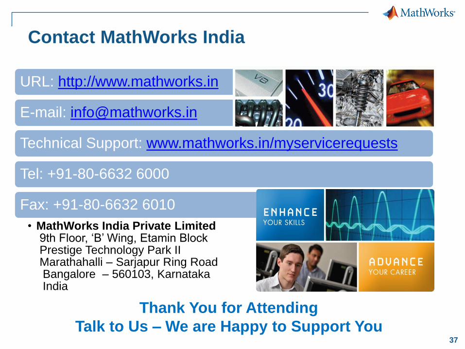
Contact MathWorks India
URL: http://www.mathworks.in
E-mail: [email protected]
Technical Support: www.mathworks.in/myservicerequests
Tel: +91-80-6632 6000
Fax: +91-80-6632 6010
• MathWorks India Private Limited9th Floor, ‘B’ Wing, Etamin BlockPrestige Technology Park IIMarathahalli – Sarjapur Ring RoadBangalore – 560103, KarnatakaIndia
Thank You for Attending
Talk to Us – We are Happy to Support You