Embed Size (px)
Citation preview

International Journal of Automation and Computing 11(6), December 2014, 588-597
DOI: 10.1007/s11633-014-0839-9
Designing Chaotic Mathematical Circuits for Solving
Practical Problems
Rene LoziLaboratory J. A. Dieudonne, UMR CNRS 7351, University of Nice-Sophia Antipolis, Parc Valrose 06108, Nice Cedex 02, France
Abstract: We introduce the paradigm of chaotic mathematical circuitry which shows some similarity to the paradigm of electroniccircuitry, especially in the frame of chaotic attractors for solving practical problems (generating hyperchaos; developing chaos basedpseudo random number generator (CPRNG) and chaotic multistream PRNG; secure communication via synchronization). They can
also be used in cryptography, generic algorithms in optimization, control, etc.
Keywords: Chaotic mathematical circuit, circuit modeling, chaos, Chua′s circuit, pseudo-random number generator.
1 Introduction
Our purpose is to build up an analogue to the paradigm ofelectric circuitry, which is the design of electronic circuits:the paradigm of chaotic mathematical circuitry, in orderto easily improve the performance of well known chaoticattractors for application purposes (chaotic cryptography,evolutionary and genetic algorithms in optimization, con-trol, etc). However, some differences occur in the analogy:Mathematical circuits are generic rather than specific likeelectric circuits.
An electronic circuit is composed of individual electroniccomponents, such as resistors, transistors, capacitors, in-ductors and diodes, connected by conductive wires throughwhich electric current can flow. The combination of com-ponents and wires allows various simple and complex oper-ations to be performed: Signals can be amplified, computa-tions can be accomplished, and data can be moved from oneplace to another. Very complex systems can be analyzedusing various sophisticated methods[1−3]. We introduce inthe same way mathematical circuits which are composedof individual components (generators, couplers, samplers,mixers, reducers and cascaders, etc.) connected throughstreams of data. The combination of such mathematicalcomponents leads to several new applications such as im-proving the performance of well known chaotic attractors(Chua, Lorenz, Rossler, etc.) for application purposes.
From a mathematical point of view, at least in orderto implement applications of chaotic behaviors, all thesechaotic attractors have the same structure: Given initialvalues and a set of parameters, they provide three streamsof data symbolized by three arrows. On the contrary, theelectric realization of their equation leads to very differentelectric circuits. In fact, mathematical circuits capture theessential of dynamics of chaotic attractors.
In Section 2, we present several symbols of generators(both continuous and discrete) used in the paradigm ofmathematical circuits, and we compare mathematical cir-
Regular paperSpecial Issue on Recent Advances on Complex Systems Control,
Modelling and Prediction IIManuscript received August 29, 2013; accepted November 4, 2013
cuits with the electric ones. In Section 3, we introduceothers circuit elements (couplers, sampler, mixer, reducerand cascader) in practical problems: generating hyper-chaos, developing chaos based pseudo random number gen-erators (CPRNGs), and chaotic multistream pseudo ran-dom number generators (Cms-PRNGs), secure communi-cation via synchronization. The conclusions are given inSection 4.
2 Elementary mathematical circuit ele-ments
2.1 Continuous generators: Chua′s cir-cuit, Rossler and Lorenz attractors
Analog electric circuits are very commonly representedby schematic diagrams, in which wires are shown as lines,and each component has a unique symbol (Fig. 1).
Fig. 1 Electrical symbols (left-hand side column) and elec-
tronic circuit symbols (right-hand side column) used for drawing
schematic diagram
We present in this section some symbols we design inorder to draw mathematical schematic diagrams. First, wedescribe generator symbols, which are, from a mathematicalpoint of view, equivalent to a battery or a variable currentgenerator in an electric circuit. In the paradigm of math-ematical circuitry, they generate a digital signal (in one orseveral dimensions) rather than an electrical current

R. Lozi / Designing Chaotic Mathematical Circuits for Solving Practical Problems 589
characterized by its voltage and intensity variations(nonetheless, a voltage or an intensity variation can be con-sidered as a physical signal which can be discretized).
This signal can be either continuous as in Chua′s cir-cuit, Lorenz or Rossler attractors or discrete as in the Lozimapping or the symmetric tent map. We consider first thecontinuous ones, inspired by the Chua′s famous circuit[4]
(Fig. 2 (a)) which contains three linear energy-storage el-ements (an inductor and two capacitors), a linear resis-tor, and a single nonlinear resistor, namely Chua′s diode(Fig. 2 (b)) with three segment linear characteristics definedby
f(vR) = m0vR +1
2(m1 − m0) [|vR + Bp| − |vR − Bp|] (1)
where the slopes in the inner and the outer regions are m0
and m1, respectively, and ±Bp denote the breakpoints.
Fig. 2 Chua′s circuit. (a) Electronic realization; (b) Three-
segment piecewise-linear v-i characteristic of nonlinear voltage
controlled resistor (Chua′s diode)
The dynamics of Chua′s circuit is governed by (2) whereVC1 , VC2 , and iL are the voltages across the capacitors C1
and C2, and the intensity of the electrical current throughthe inductor L, respectively.
⎧⎪⎪⎪⎪⎨
⎪⎪⎪⎪⎩
C1dvC1
dt= G(vC2 − vC1) − f(vC1)
C2dvC2
dt= G(vC1 − vC2) + iL
LdiLdt
= −vC2 .
(2)
Equation (2) can be transformed into the system ofthree first-order autonomous differential equations whose
dimension-less form is⎧⎪⎨
⎪⎩
x = α(y − x − f(x))
y = x − y + z
z = −βy
f(x) = bx +1
2(a − b) [|x + 1| − |x − 1|]
(3)
for which the set of parameter values
α = 15.60, b = 28.58, a = − 1
7, b =
2
7
is very often used in order to generate chaotic signal. Even ifthe scheme of Fig. 2 (a) is easily understandable by electricengineers, it is of no help to build a device using mathe-matical properties of chaos (like a secure communicationsystem based on it[5]). This is why it is more useful torepresent Chua′s circuit as a chaos generator by the di-agram of Fig. 3 (a). On this detailed flowchart of con-tinuous generator, the solid line arrows coming out fromthe generator represent the three components of the signalx(t) = (x(t), y(t), z(t)), the dashed line arrow which pointsat λ stands for the parameter value, and the dot line arrowwhich points at x0 = x(0) indicates the given initial value.
If there is no ambiguity on the nature of the generatorused, the symbol can be simplified as in Fig. 3 (b).
Fig. 3 Continuous generator. (a) Chua′s circuit; (b) Simplified
symbol
The diagram defined above is suitable, even if we useothers types of equations, for generating streams of data,provided the number of streams is the same as in Chua′scircuit (if it is not the case, more arrows can be added(Fig. 9)). For example, the Lorenz attractor[6]
⎧⎪⎨
⎪⎩
x = −σ(x + y)
y = ρx − y − xz
z = xy − βz
(4)
often studied using the parameter values
σ = 10, ρ = 28, β =8
3
and the Rossler attractor[7]
⎧⎪⎨
⎪⎩
x = −y − z
y = x + ay
z = b + z(x − c)
(5)
590 International Journal of Automation and Computing 11(6), December 2014
for which the parameter values
a = 0.2, b = 0.2, c = 5.7
exhibits a strange attractor.In the next subsection, we show that from a mathemati-
cal point of view, in order to build an application of chaoticbehaviors, all the attractors generated by these equationshave the same structure: Given initial values and a set ofparameters, they provide three streams of data symbolizedby three arrows. Quite the contrary the electric realizationof their equation leads to very different electric circuits.
2.2 Mathematical circuits vs. electric cir-cuits
Although our goal is to build up mathematical circuitsthat are analogue to the paradigm of electric circuitry, thereare some differences between both kinds of circuits. Mathe-matical circuits are generic rather than specific like electriccircuits. The symbol of Fig. 3 (b) shall apply to a class ofchaotic (or non-chaotic as well) attractors in 3-dimensionalphase space, for instance Chua, Lorenz and Rossler attrac-tors. In contrast, electric implementation of such attractorslooks very different. Fig. 2 (a) displays the electric realiza-tion of Chua′s circuit which displays Chua attractor on os-cilloscope screen.
One among several realizations of Lorenz′s circuit[8] isshowed in Fig. 4. The variables, x, y, z of (4) are thevoltages across capacitors C1, C2, and C3 after a suitablerescaling.
Fig. 4 Lorenz′s circuit. (a) Schematic diagram of a simple cir-
cuit. Analog multipliers M1 and M2 are configured as current
output devices; (b) Schematic diagram of a generic analog mul-
tiplier Mi configured as a current output device[8]
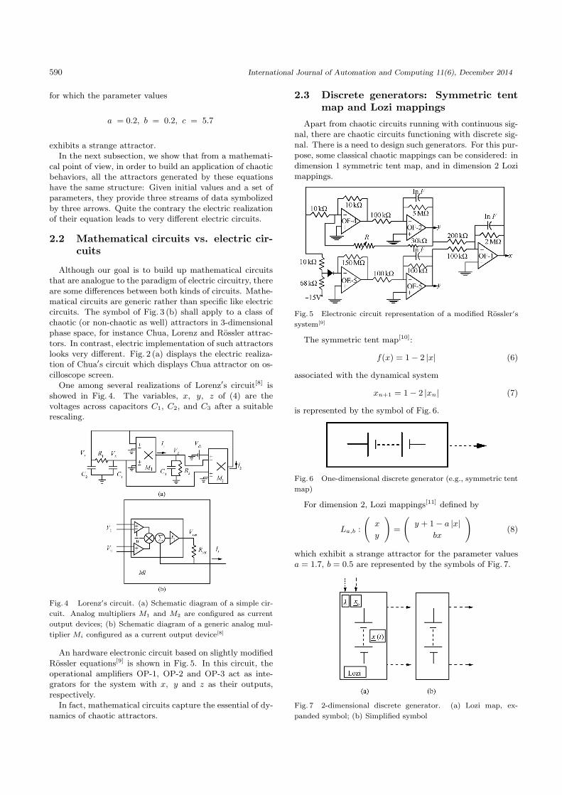
An hardware electronic circuit based on slightly modifiedRossler equations[9] is shown in Fig. 5. In this circuit, theoperational amplifiers OP-1, OP-2 and OP-3 act as inte-grators for the system with x, y and z as their outputs,respectively.
In fact, mathematical circuits capture the essential of dy-namics of chaotic attractors.
2.3 Discrete generators: Symmetric tentmap and Lozi mappings
Apart from chaotic circuits running with continuous sig-nal, there are chaotic circuits functioning with discrete sig-nal. There is a need to design such generators. For this pur-pose, some classical chaotic mappings can be considered: indimension 1 symmetric tent map, and in dimension 2 Lozimappings.
Fig. 5 Electronic circuit representation of a modified Rossler′s
system[9]
The symmetric tent map[10]:
f(x) = 1 − 2 |x| (6)
associated with the dynamical system
xn+1 = 1 − 2 |xn| (7)
is represented by the symbol of Fig. 6.
Fig. 6 One-dimensional discrete generator (e.g., symmetric tent
map)
For dimension 2, Lozi mappings[11] defined by
La,b :
(x
y
)
=
(y + 1 − a |x|
bx
)
(8)
which exhibit a strange attractor for the parameter valuesa = 1.7, b = 0.5 are represented by the symbols of Fig. 7.
Fig. 7 2-dimensional discrete generator. (a) Lozi map, ex-
panded symbol; (b) Simplified symbol

R. Lozi / Designing Chaotic Mathematical Circuits for Solving Practical Problems 591
Remark 1. In the rest of this article, we use solid linearrow for continuous signal x(t), and dashed line arrow fordiscrete signal xn.
2.4 Other circuits elements
Rather than to give a tedious list of elementary mathe-matical components used for mathematical circuit design,we will introduce them each time they are first used for apractical purpose.
That list includes: generators, couplers, sampler, mixer,reducer and cascader. They are connected through streamsof data represented by continuous or dashed line and ar-rows.
3 Solving practical problems
3.1 Building up hyperchaotic electronicand mathematical circuits using a ringcoupler
As highlighted in [12], “One of the most interesting fea-tures of Chua′s circuit is its easy electronic implementation.Soon after its inception, the circuit was studied experi-mentally thereby confirming the presence of double scrollin it. Due to the presence of linear passive devices, thetask of designing Chua′s circuit was reduced to designingChua′s diode. In fact, unlike many other chaotic systems,the presence of grounded capacitors and inductors makesChua′s circuit a very-large-scale integration (VLSI) friendlychaotic system.”
However, Chua′s circuit provides only 3-dimensionalchaos, as Figs. 3 (a) and (b), with its three arrows empha-sized. For studying a more complex chaotic behavior calledhyperchaos, which has been reported in hydrodynamics andsemiconductor devices, one has to combine the behavior ofseveral Chua′s circuits and couple them in various ways.
The experimental observation of hyperchaotic attractorsin open and closed chains of Chua′s circuits was reportedin 1994[13] . The layout of the five identical coupled Chua′scircuits forming a ring is shown in Fig. 8.
The state equations of this circuit are as (9). Through
identifying symbols (V(i)
C1, V
(i)C2
, I(i)L ) in each Chua′s circuit
with (xi, yi, zi), the state equations of the circuit can betranslated into the system of fifteen differential equationsshown in (10), and the electronic circuit of Fig. 8 is symbol-ized by the mathematical circuit of Fig. 9.
In Fig. 9, the double rounded arrows symbolize the cou-pling of one Chua′s circuit to the next one. In order torepresent the coupling between mathematical equations, de-pending on the nature of the coupling, we can use two dif-ferent symbols: The ring coupler corresponding to the cou-pling of one generator to the next one (Fig. 9) and the fullcoupler when the coupling involves more connections be-
tween the couplers as shown in the next subsection (Fig. 10).
⎧⎪⎪⎪⎪⎪⎪⎪⎪⎪⎪⎪⎪⎪⎪⎪⎪⎪⎪⎪⎪⎪⎪⎪⎪⎪⎪⎪⎪⎪⎪⎪⎪⎪⎪⎪⎪⎪⎨
⎪⎪⎪⎪⎪⎪⎪⎪⎪⎪⎪⎪⎪⎪⎪⎪⎪⎪⎪⎪⎪⎪⎪⎪⎪⎪⎪⎪⎪⎪⎪⎪⎪⎪⎪⎪⎪⎩
C1
dv(1)C1
dt= G
(v(1)C2
− v(1)C1
)− f
(v(1)C1
)
C2
dv(1)C2
dt= G
(v(1)C1
− v(1)C2
)+ i
(1)L + K1
(v(2)C2
− v(1)C2
)
Ldi
(1)L
dt= −v
(1)C2
C1
dv(2)C1
dt= G
(v(2)C2
− v(2)C1
)− f
(v(2)C1
)
C2
dv(2)C2
dt= G
(v(2)C1
− v(2)C2
)+ i
(2)L + K2
(v(3)C2
− v(2)C2
)
Ldi
(2)L
dt= −v
(2)C2
· · ·
C1
dv(5)C1
dt= G
(v(5)C2
− v(5)C1
)− f
(v(5)C1
)
C2
dv(5)C2
dt= G
(v(5)C1
− v(5)C2
)+ i
(5)L + K5
(v(1)C2
− v(5)C2
)
Ldi
(5)L
dt= −v
(5)C2
(9)⎧⎪⎪⎪⎪⎪⎪⎪⎪⎪⎪⎪⎪⎪⎪⎪⎪⎨
⎪⎪⎪⎪⎪⎪⎪⎪⎪⎪⎪⎪⎪⎪⎪⎪⎩
x1 = α(y1 − x1 − f(x1))
y1 = x1 − y1 + z1 + k1(y2 − y1)
z1 = −βy1
x2 = α(y2 − x2 − f(x2))
y2 = x2 − y2 + z2 + k2(y3 − y2)
z2 = −βy2
· · ·x5 = α(y5 − x5 − f(x5))
y5 = x5 − y5 + z5 + k5(y1 − y5)
z5 = −βy5.
(10)
3.2 Developing chaos based pseudo ran-dom number generator (CPRNG) us-ing full coupler, sampler, mixer, andreducer
It is well known that industrial mathematics is greedy ofmassive amounts of random and pseudorandom numbers,as they are vital in many areas of modern technology suchas fast communication systems, economy, equity tradingand in a wide range of engineering applications. US andEuropean patents using discrete maps for providing thesenumbers are registered by specialists of discrete dynamicalsystems[14,15]. We have recently proposed efficient chaoticpseudo random number generators (CPRNGs)[16]. Theyare based on the ultra weak multidimensional couplingof p 1-dimensional dynamical systems which preserve thechaotic properties of the continuous models in numericalexperiments. Combined with chaotic sampling and mixingprocesses, ultra weak coupling leads to families of CPRNGswhich are very effective[17].
It was shown a few years ago[18] that the ultra-weak cou-pling of several logistic or symmetric tent maps (6) allowsthe production of long series of chaotic numbers equallydistributed over the interval [−1, 1] of the real line.

592 International Journal of Automation and Computing 11(6), December 2014
The system of p-coupled tent map is given by
Xn+1 = F (Xn) = A(f(Xn)) (11)
where Xn =
⎛
⎜⎜⎝
x1n
...
xpn
⎞
⎟⎟⎠ , f(Xn) =
⎛
⎜⎜⎝
f(x1n)
...
f(xpn)
⎞
⎟⎟⎠, and A is
the matrix that is shown at the bottom of this page.The design of the corresponding mathematical circuit is
displayed in Fig. 10.
Fig. 8 Five identical coupled Chua′s circuits forming a ring[13]
Fig. 9 Mathematical circuit of five identical coupled Chua′s cir-
cuits forming a ring
At this point it is important to note that chaotic num-bers are not pseudo-random numbers because the plot ofthe couples of any component (xl
n, xln+1) of the iterated
f points (Xn, Xn+1) in the corresponding phase f planereveals the map used as 1-dimensional dynamical systemsto generate them via (11). Nevertheless a family of en-hanced CPRNG in order to compute very fast long series
of pseudorandom numbers with desktop computer has beenintroduced[19]. The way to conceal the chaotic genuine func-tion is the ultra-weak coupling mechanism which has beenimproved.
Fig. 10 Circuit of ultraweak coupling of p 1-dimensional chaotic
map
In order to hide f of (11) in the phase space (xln, xl
n+1),the sequence (xl
0, xl1, xl
2, · · · , xln, xl
n+1, · · · ) generated bythe l-th component of Xn is sampled chaotically, selectingxl
n every time the value of xmn the m-th component of Xn, is
strictly greater than a threshold T belonging to the interval[−1, 1] of the real line.
The pseudo-code, for computing such chaotically sub-sampled numbers is
X0 = (x10, x2
0, · · · xp−10 , xp
0) = seed
n = 0; q = 0;
do {while n < N
do {while xmn < T
compute (x1n, x2
n, · · · , xp−1n , xp
n); n + +}compute (x1
n, x2n, · · · , xp−1
n , xpn);
then n(q) = n; xq = x1n(q); n + +; q + +}.
This chaotic under-sampling is possible due to the inde-pendence of each component of the iterated points Xn vs.the others[19]. We introduce the symbol of this sampler onthe right-hand side of Fig. 11 in order to give a schematicrepresentation of this chaotic under-sampling process.
Fig. 11 Circuit of enhanced CPRNG based on chaotic under-
sampling
A =
⎛
⎜⎜⎜⎜⎜⎜⎜⎜⎜⎜⎜⎜⎜⎜⎝
ε1,1 = 1 −j=p∑
j=2
ε1,j ε1,2 · · · ε1,p−1 ε1,p
ε2,1 ε2,2 = 1 −j=p∑
j=1,j �=2
ε2,j · · · ε2,p−1 ε2,p
.... . .
......
.... . .
......
εp,1 · · · · · · εp,p−1 εp,p = 1 −j=p−1∑
j=1
εp,j
⎞
⎟⎟⎟⎟⎟⎟⎟⎟⎟⎟⎟⎟⎟⎟⎠
.

R. Lozi / Designing Chaotic Mathematical Circuits for Solving Practical Problems 593
A second mechanism can improve the unpredictability ofthe pseudo-random sequence generated as above, using syn-ergistically all the components of the vector Xn instead oftwo.
Given p − 1 thresholds
0 < T1 < T2 < · · ·Tp−1 < 1
which define a partition J1, J2, · · · , Jp−1 of the interval[−1, 1], the pseudo-code for computing such chaotically sub-sampled numbers is
X0 = (x10, x2
0, · · · xp−10 , xp
0) = seed
n = 0; q = 0;
do {while n < N
do {while xmn ∈ J0
compute (x1n, x2
n, · · · , xp−1n , xp
n); n + +}compute(x1
n, x2n, · · · , xp−1
n , xpn)
let k be such that xpn ∈ Jk
then n(q) = n; xq = xkn(q); n + +; q + +}.
We draw the symbol on the right-hand side of Fig. 12 inorder to give a schematic representation of the chaotic mix-ing process. For sake of simplicity, we have only displayeda circuit with three 1-dimensional generators. However, themixing process runs better when more generators are cou-pled.
Fig. 12 Circuit of enhanced CPRNG based on chaotic mixing
We can say that the design of mathematical circuitincluding couplers, samplers or mixers allows the emer-gence of complexity in chaotic systems which leads torandomness[17].
We introduce now another process which can directlyprovide random numbers without sampling or mixing, al-though it is possible to combine those processes with it.The idea underlying this process is to confine on [−1, 1]p
considered as a torus, a ring of p-coupled symmetric tentmaps (or logistic maps)[20].
Consider the equalities:⎧⎪⎪⎪⎪⎪⎪⎪⎪⎪⎪⎨
⎪⎪⎪⎪⎪⎪⎪⎪⎪⎪⎩
x1n+1 = 1 − 2
∣∣x1
n
∣∣ + k1x
2n
...
xmn+1 = 1 − 2 |xm
n | + kmxm+1n
...
xp−1n+1 = 1 − 2
∣∣xp−1
n
∣∣ + kp−1x
pn
xpn+1 = 1 − 2 |xp
n| + kpx1n
(12)
where the parameters ki = ∓1. In order to confine the vari-ables xi
n+1 on the torus [−1, 1]p, we do for every iteration
the transform:
{add 2, if (xj
n+1 < −1)
substract 2, if (xjn+1 > 1).
(13)
We design a new symbol: the reducer, on the right-handside of Fig. 13, in order to give a schematic representationof the projection of the variable on the torus. For the sakeof simplicity, we have again displayed a circuit with onlythree 1-dimensional generators. However, this new pseudo-random number generator works better when more genera-tors are coupled as in the previous example.
Fig. 13 Reducer for the circuit (12) and the transform (13) with
p = 3
The particularity of this coupling is that each variable xj
is coupled only with itself and xj+1, i.e., using a ring cou-pler as shown in Fig. 13. At first glance, in order to enrichthe random properties of the map, it could seem interestingto add supplementary cross couplings between these vari-ables, i.e., using a full coupler as in Fig. 10. However, inthis case, a full coupling is inappropriate because it wouldincrease the determinism and therefore deteriorate the sta-tistical properties which we are looking for.
To evaluate the random property of these generators,the set of National Institute of Standards and Technology(NIST) tests[21] have been used.
The random property validations of both a 4-dimensionalsystem and a 10-dimensional one have been carried out[22].For this purpose, the chaotic carrier output needs to bequantized and binarized (0 and 1) in order to be validatedas random using NIST tests. Therefore, different methodsof binarization (converting real signals to binary ones) havebeen implemented and compared.
A first 1-bit binarization has been applied to the systemoutput (12, 13), defined as yn = xj
n with j ∈ [[1, p]],
{b = 1, if (yn � 0)
b = 0, else.(14)
The results proved to be highly sensitive to the typeof binarization. Eventually, after testing several differentmethods, a 32-bit binarization was chosen as the most suit-able solution. Because the system is confined to the p-dimensional torus [−1, 1]p, 31 bits are assigned to representthe decimal part, and 1 bit to the sign. To illustrate theresults, the NIST tests for the 4-dimensional system withparameters ki ∈ (−1)i+1 are shown in Fig. 14. The chosenconditions are: The length of the original sequence = 108
bits, the length of bit string = 106 bits, the quantity of bit

594 International Journal of Automation and Computing 11(6), December 2014
Fig. 14 Example of NIST Test for ki = (−1)i+1, i = 1, 2, · · · , 4 , each sequence of components satisfies the NIST test for randomness
strings = 100. The output of the system has been arbitrarychosen to be y = x4
n.Furthermore, as the results show their independence of
the initial conditions, every bit string in this test is the re-sulting sequence of a different randomly chosen initial con-dition. The criterion for a successful test is that the p-valuehas to be superior to the significance level (0.01 for thiscase). For the present model, all tests were successful thusthe sequences can be accepted as random.
3.3 Chaotic multistream pseudo randomnumber generators (Cms-PRNG)
It is possible to combine several equations in order todesign chaotic multistream pseudo random number gener-ators (Cms-PRNGs) or combine several processes in orderto generate uncorrelated sequences of pseudo-random num-bers, possessing a large number of keys for a cryptographicuse.
This is simply obtained by adding a full coupler as akeyer as shown in the circuit of Fig. 15, corresponding to(15) with the reduction process of (13).
⎧⎪⎪⎪⎪⎪⎪⎪⎪⎪⎪⎪⎪⎪⎪⎪⎪⎪⎪⎪⎪⎪⎪⎪⎪⎪⎪⎪⎪⎪⎪⎪⎨
⎪⎪⎪⎪⎪⎪⎪⎪⎪⎪⎪⎪⎪⎪⎪⎪⎪⎪⎪⎪⎪⎪⎪⎪⎪⎪⎪⎪⎪⎪⎪⎩
x1n+1 = 1 − 2 |x1
n| + k1
[(
1 −p∑
j=3ε1,j
)
x2n +
p∑
j=3ε1,jxj
n
]
...
xmn+1 = 1 − 2 |xm
n | + km
[(
1 −p∑
j=1,j �=m;m+1εm,j
)
xm+1n +
p∑
j=1,j �=m;m+1εm,jxj
n
]
..
.
xp−1n+1 = 1 − 2 |xp−1
n | + kp−1
[(
1 −p−2∑
j=1εp−1,j
)
xpn+
p−2∑
j=1εp−1,jxj
n
]
xpn+1 = 1 − 2 |xp
n| + kp
[(
1 −p−1∑
j=2εp,j
)
x1n +
p−1∑
j=2εp,jxj
n
]
.
(15)
Fig. 15 Circuit of Cms-PRNG with only 3 streams
3.4 Secure communication via chaotic syn-chronization using a cascader
The synchronization of two Chua′s circuits was studiedexperimentally eight years after its discovery in 1992[23] ,soon followed by its application to encrypted transmission.In 1992, the first laboratory demonstration of a secure com-munication system using a chaotic signal for masking pur-poses was built[24]. The technique exploited the chaoticsynchronization in order to recover the signal[25]. While the“transmitter”[25] is a direct implementation of the methodproposed in [24], the “receiver” differs from the computersimulation approach, because it actually contains two sub-systems of the “chaotic transmitter” (Chua′s circuit).
The mathematical translation of the dynamics of the cir-cuit used in [25] for the experimental demonstration of se-cure communication is as follows: The basic building blockis a Chua′s circuit, and the dynamics of which is given bythe Chua′s equations (3). The noise-like signal u(t) is usedto hide the message. If s(t) is an information-bearing sig-nal, the transmitted one is r(t) = u(t) + s(t), where s(t) isassumed to have a significantly lower power level than thatof u(t). Hence the signal s(t) is effectively “masked”.
Two sub-systems compose the receiver.The first sub-system is driven by the transmitted signal
r(t):
{v1 = r(t) − v1 + w1
w1 = −βv1.(16)
The second one is driven by the signal v1(t) as
u2 = α[v1 − u2 − f(u2)]. (17)
The signal s(t) is then recovered using
s2(t) = r(t) − u2(t) ≈ s(t). (18)
Actually the dynamics of the experimental set-up(Fig. 16) is described by
{u2 = α(v1 − u2 − f(u2))
w2 = −βv1.(19)
Remark 2. As long as we do not need w2(t) to recovers2(t), we continue to use (18) instead of (19) in the followingimproved system.
Remark 3. In both implementations (electronic circuitrealization (Fig. 17) and computer simulation (Fig. 16)) of
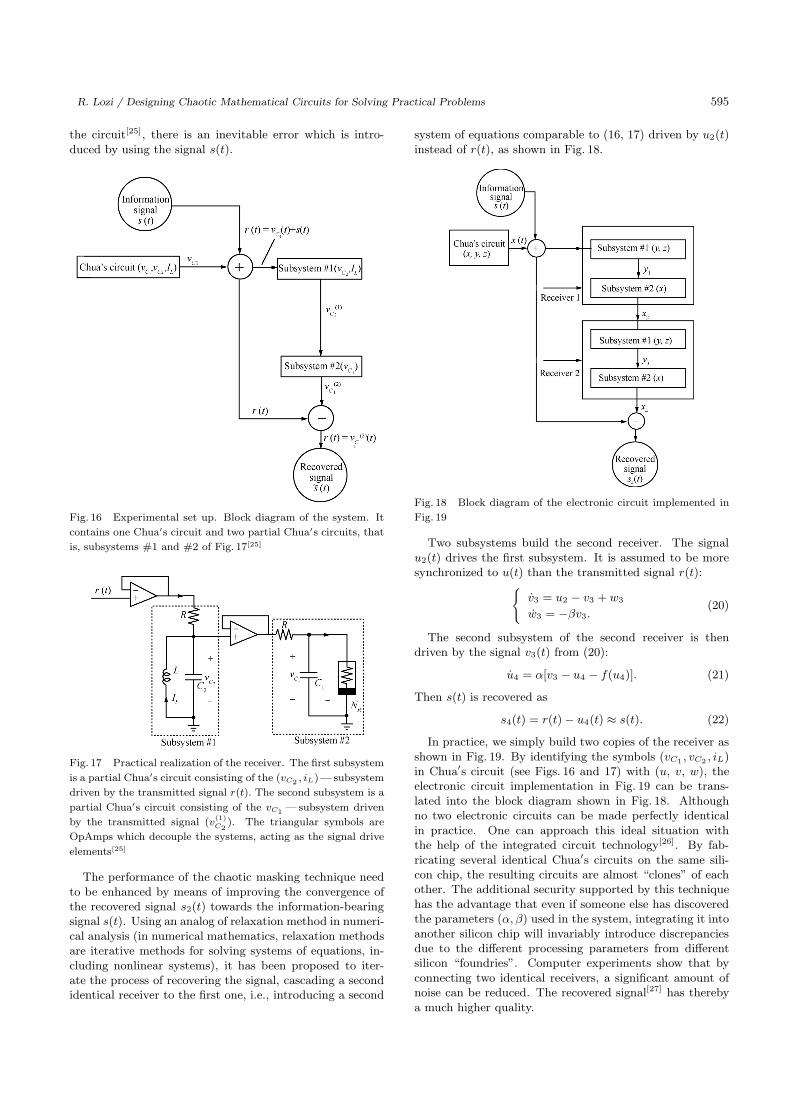
R. Lozi / Designing Chaotic Mathematical Circuits for Solving Practical Problems 595
the circuit[25], there is an inevitable error which is intro-duced by using the signal s(t).
Fig. 16 Experimental set up. Block diagram of the system. It
contains one Chua′s circuit and two partial Chua′s circuits, that
is, subsystems #1 and #2 of Fig. 17[25]
Fig. 17 Practical realization of the receiver. The first subsystem
is a partial Chua′s circuit consisting of the (vC2 , iL)—subsystem
driven by the transmitted signal r(t). The second subsystem is a
partial Chua′s circuit consisting of the vC1 —subsystem driven
by the transmitted signal (v(1)C2
). The triangular symbols are
OpAmps which decouple the systems, acting as the signal drive
elements[25]
The performance of the chaotic masking technique needto be enhanced by means of improving the convergence ofthe recovered signal s2(t) towards the information-bearingsignal s(t). Using an analog of relaxation method in numeri-cal analysis (in numerical mathematics, relaxation methodsare iterative methods for solving systems of equations, in-cluding nonlinear systems), it has been proposed to iter-ate the process of recovering the signal, cascading a secondidentical receiver to the first one, i.e., introducing a second
system of equations comparable to (16, 17) driven by u2(t)instead of r(t), as shown in Fig. 18.
Fig. 18 Block diagram of the electronic circuit implemented in
Fig. 19
Two subsystems build the second receiver. The signalu2(t) drives the first subsystem. It is assumed to be moresynchronized to u(t) than the transmitted signal r(t):
{v3 = u2 − v3 + w3
w3 = −βv3.(20)
The second subsystem of the second receiver is thendriven by the signal v3(t) from (20):
u4 = α[v3 − u4 − f(u4)]. (21)
Then s(t) is recovered as
s4(t) = r(t) − u4(t) ≈ s(t). (22)
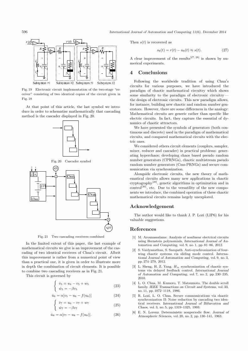
In practice, we simply build two copies of the receiver asshown in Fig. 19. By identifying the symbols (vC1 , vC2 , iL)in Chua′s circuit (see Figs. 16 and 17) with (u, v, w), theelectronic circuit implementation in Fig. 19 can be trans-lated into the block diagram shown in Fig. 18. Althoughno two electronic circuits can be made perfectly identicalin practice. One can approach this ideal situation withthe help of the integrated circuit technology[26]. By fab-ricating several identical Chua′s circuits on the same sili-con chip, the resulting circuits are almost “clones” of eachother. The additional security supported by this techniquehas the advantage that even if someone else has discoveredthe parameters (α, β) used in the system, integrating it intoanother silicon chip will invariably introduce discrepanciesdue to the different processing parameters from differentsilicon “foundries”. Computer experiments show that byconnecting two identical receivers, a significant amount ofnoise can be reduced. The recovered signal[27] has therebya much higher quality.
596 International Journal of Automation and Computing 11(6), December 2014
Fig. 19 Electronic circuit implementation of the two-stage “re-
ceiver” consisting of two identical copies of the circuit given in
Fig. 18
At that point of this article, the last symbol we intro-duce in order to schematise mathematically that cascadingmethod is the cascader displayed in Fig. 20.
Fig. 20 Cascader symbol
Fig. 21 Two cascading receivers combined
In the limited extent of this paper, the last example ofmathematical circuits we give is an improvement of the cas-cading of two identical receivers of Chua′s circuit. Albeitthis improvement is rather from a numerical point of viewthan a practical one, it is given in order to illustrate morein depth the combination of circuit elements. It is possibleto combine two cascading receivers as in Fig. 21.
This circuit is governed by{
v5 = u4 − v5 + w5
w5 = −βv5(23)
u6 = α[v5 − u6 − f(u6)] (24){
v7 = u6 − v7 + w7
w7 = −βv7(25)
u8 = α[v7 − u8 − f(u8)]. (26)
Then s(t) is recovered as
s8(t) = r(t) − u8(t) ≈ s(t). (27)
A clear improvement of the results[27, 28] is shown by nu-merical experiments.
4 Conclusions
Following the worldwide tradition of using Chua′scircuits for various purposes, we have introduced theparadigm of chaotic mathematical circuitry which showssome similarity to the paradigm of electronic circuitry —the design of electronic circuits. This new paradigm allows,for instance, building new chaotic and random number gen-erators. However, there are some differences in the analogy:Mathematical circuits are generic rather than specific likeelectric circuits. In fact, they capture the essential of dy-namics of chaotic attractors.
We have presented the symbols of generators (both con-tinuous and discrete) used in the paradigm of mathematicalcircuits, and compared mathematical circuits with the elec-tric ones.
We considered others circuit elements (couplers, sampler,mixer, reducer and cascader) in practical problems: gener-ating hyperchaos; developing chaos based pseudo randomnumber generators (CPRNGs), chaotic multistream pseudorandom number generators (Cms-PRNGs) and secure com-munication via synchronization.
Alongside electronic circuits, the new theory of math-ematical circuits allows many new applications in chaoticcryptography[29], genetic algorithms in optimization and incontrol[30], etc. Due to the versatility of the new compo-nents we introduce, the combined operation of these chaoticmathematical circuits remains largely unexplored.
Acknowledgement
The author would like to thank J. P. Lozi (LIP6) for hisvaluable suggestions.
References
[1] M. Arounassalame. Analysis of nonlinear electrical circuitsusing Bernstein polynomials. International Journal of Au-tomation and Computing, vol. 9, no. 1, pp. 81–86, 2012.
[2] S. Vaidyanathan, S. Sampath. Anti-synchronization of four-wing chaotic systems via sliding mode control. Interna-tional Journal of Automation and Computing, vol. 9, no. 3,pp. 274–279, 2012.
[3] L. Sheng, H. Z. Yang. H∞ synchronization of chaotic sys-tems via delayed feedback control. International Journalof Automation and Computing, vol. 7, no. 2, pp. 230–235,2010.
[4] L. O. Chua, M. Kumoro, T. Matsumoto. The double scrollfamily. IEEE Transactions on Circuit and Systems, vol. 33,no. 11, pp. 1072–1118, 1986.
[5] R. Lozi, L. O. Chua. Secure communications via chaoticsynchronization II: Noise reduction by cascading two iden-tical receivers. International Journal of Bifurcation andChaos, vol. 3, no. 5, pp. 1319–1325, 1993.
[6] E. N. Lorenz. Deterministic nonperiodic flow. Journal ofAtmospheric Sciences, vol. 20, no. 2, pp. 130–141, 1963.

R. Lozi / Designing Chaotic Mathematical Circuits for Solving Practical Problems 597
[7] O. E. Rossler. Chaotic behavior in simple reaction system.Zeitschrift fur Naturforschung, vol. A31, pp. 259–264, 1976.
[8] J. N. Blakely, M. B. Eskridge, N. J. Corron. A simple Lorenzcircuit and its radio frequency implementation. Chaos,vol. 17, no. 2, Article no. 023112, 2007.
[9] N. Datta, M. K. Mandal. Realisation of electronic circuitbased on modified rossler system and its application in se-cure communication. Elixir Computer Science and Engi-neering, vol. 49, pp. 9845–9848, 2012.
[10] J. C. Sprott. Chaos and Time-series Analysis, Oxford, UK:Oxford University Press, 2003.
[11] R. Lozi. Un attracteur etrange (?) du type attracteur deHenon. Journal de Physique, vol. 39, no. C5, pp. 9–10, 1978.
[12] G. Gandhi. Electronic Realizations of Chaotic Circuits:From Breadboard to Nanotechnology, Ph. D. dissertation,Peter Pazmany Catholic University, Budapest, Hungary,2008.
[13] T. Kapitaniak, L. O. Chua, G. Q. Zhong. Experimental hy-perchaos in coupled Chua′s circuits. IEEE Transactions onCircuits and Systems I: Fundamental Theory and Applica-tions, vol. 41 no. 7, pp. 499–503, 1994.
[14] M. V. Petersen, H. M. Sorensen. Method of GeneratingPseudo-random Numbers in an Electronic Device, and aMethod of Encrypting and Decrypting Electronic Data,Patent No. 7170997, USA, 2007.
[15] D. Ruggiero, D. Mascolo, I. Pedaci, P. Amato. Method ofgenerating successions of pseudo-random bits or numbers,Patent No. 20060251250 A1, USA, 2006.
[16] R. Lozi. Complexity Leads to Randomness in Chaotic Sys-tems. Mathematics in Science and Technology: Mathemat-ical Methods, Models and Algorithms in Science and Tech-nology, A. H. Siddiqi, R. C. Singh, P. Manchanda, Eds.,Singapore: World Scientific Publisher, pp. 93–125, 2001.
[17] R. Lozi. Emergence of randomness from chaos. Interna-tional Journal of Bifurcation and Chaos, vol. 22, no. 2, Ar-ticle no. 1250021, 2012.
[18] R. Lozi. Giga-periodic orbits for weakly coupled tent andlogistic discretized maps. Modern Mathematical Models,Methods and Algorithms for Real World Systems, A. H.Siddiqi, I. S. Duff, O. Christensen, Eds., New Delhi, India:Anamaya Publishers, pp. 80–124, 2006.
[19] R. Lozi. New enhanced chaotic number generators. In-dian Journal of Industrial and Applied Mathematics, vol. 1,no. 1, pp. 1–23, 2008.
[20] A. Espinel, I. Taralova, R. Lozi. Dynamical and statisticalanalysis of a new Lozi function for random numbers gen-eration. In Proceedings of the 5th International Conferenceon Physics and Control, Leon, Spain, IPACS open AccessElectronic Library and Applications, pp. 5–8, 2011.
[21] A. Rukhin, J. Soto, J. Nechvatal, M. Smid, E. Barker.A Statistical Test Suite for Random and PseudorandomNumber Generators for Cryptographic Applications, NIST(2001), [Online], Available: http://csrc.nist.gov/rng/, Au-gust 28, 2013.
[22] A. E. Rojas, I. Taralova, R. Lozi. New alternate ring-coupled map for multi-random number generation. Journalof Nonlinear Systems and Applications, vol. 4, no. 1, pp. 64–69, 2013.
[23] L. O. Chua, L. Kocarev, K. Eckert, M. Itoh. Experimen-tal chaos synchronization in Chua′s circuit. InternationalJournal of Bifurcation and Chaos, vol. 2 no. 3, pp. 705–708,1992.
[24] A. V. Oppenheim, G. W. Wornell, S. H. Isabelle, K. M.Cuomo. Signal processing in the context of chaotic signals.In Proceedings of IEEE International Conference on Acous-tics, Speech, and Signal Processing, IEEE, San Francisco,CA, USA, pp. 117–120, 1992.
[25] L. Kocarev, K. S. Halle, K. Eckert, L. O. Chua, U. Parlitz.Experimental demonstration of secure communications viachaotic synchronization. International Journal of Bifurca-tion and Chaos, vol. 2, no. 3, pp. 709–713, 1992.
[26] M. Delgado-Restituto, A. Rodrıguez-Vasquez. A CMOSmonolithic Chua′s circuit. Journal of Circuits, Systems andComputers, vol. 3, no. 2, pp. 259–268, 1993.
[27] M. A. Aziz Alaoui, R. Lozi. Secure communications viachaotic synchronization in Chua′s circuit: Numerical anal-ysis of the errors of the recovered signal. In Proceedings ofNonlinear Theory and Its Application, Kagoshima, Japan,pp. 145–148, 1994.
[28] R. Lozi. Secure communications via chaotic synchroniza-tion in Chua′s circuit and Bonhoeffer-Van der Pol equation:Numerical analysis of the errors of the recovered signal. InProceedings of IEEE International Symposium on Circuitsand Systems, IEEE, Seattle, WA, USA, vol. 1, pp. 684–687,1995.
[29] R. Lozi. Engineering of Mathematical Chaotic Circuits.Nostradamus 2013: Prediction, Modeling and Analysis ofComplex Systems, Advances in Intelligent Systems andComputing, I. Zelinka, G. Chen, O. E. Rossler, V. Snasel,A. Abraham, Eds., Switzerland: Springer, vol. 210, pp. 17–29, 2013.
[30] M. Pluhacek, R. Senkerik, D. Davendra, I. Zelinka. Design-ing PID controller for DC motor system by means of en-hanced PSO algorithm with discrete chaotic Lozi map. SoftComputing Models in Industrial and Environmental Ap-plications Advances in Intelligent Systems and Computing,vol. 188, pp. 475–483, 2013.
Rene Lozi received his Ph. D. degree inbifurcation theory from University of Nice(France) in 1975 and the French State The-sis from University of Nice under the su-pervision of Professor Rene Thom in 1983.As an assistant professor, Laboratoire J. A.Dieudonne, University of Nice (1974–1976),he spent 15 years as a responsible for re-search at CNRS (1974–1990) and becamefull professor in 1990 at the same university.
He served as the director of Institut Universitaire de Formationdes Maıtres (IUFM) during 2001–2006, and as vice-chairman ofthe French Board of Directors of IUFM (2004–2006). In 2011,he became a full professor of Exceptional Class (the highest rankin French university). He is the member of the Editorial Boardof Indian Journal of Industrial and Applied Mathematics andJournal of Nonlinear Systems and Applications, and member ofthe Honorary Editorial Board of International Journal of Bifur-cation and Chaos. He is also a member of the InteruniversityGroup of Research DYCOEC, GdR 2984 of C.N.R.S. (Dynam-ics and control of complex sets), and the International Physicsand Control Society (IPACS, St Petersburg, Russia). He wasamong the founders of the Indian Society of Industrial and Ap-plied Math (ISIAM) in 1989. In 1977, he discovered a particularmapping of the plane producing a very simple strange attrac-tor (now known as the “Lozi map”). He has worked in thisfield with renowned researchers, such as Professors Leon Chua(inventor of “Chua circuit”), and Alexander Sharkovsky (whointroduced the “Sharkovsky′s order”). He has been a visitingprofessor for several periods to the University of Kyoto and Uni-versity of Tokushima in Japan and University of Berkley, USA.
His research interests include complexity and emergences the-ories, dynamical systems, bifurcation and chaos, control of chaosand cryptography based chaos.
E-mail: [email protected]