Embed Size (px)
Citation preview
DESIGN & TECHNICAL MANUAL
AIR CONDITIONERCassette type
INDOOR AUXG18LRLBAUXG24LRLBAUXG30LRLBAUXG36LRLBAUXG45LRLBAUXG54LRLB
OUTDOOR
AOYG18LBCAAOYG24LBCA
AOYG30LBTAAOYG36LBTA
AOYG45LBTAAOYG54LBTA
DR_AU002EF_042016.04.22
Notices:• Product specifications and design are subject to change without notice for future improvement.• For further details, please check with our authorized dealer.
Copyright © 2015, 2016 Fujitsu General Limited. All rights reserved.

CONTENTS (continued)
Part 1. INDOOR UNIT ........................................................................1
1. Product features ......................................................................................21-1. Model lineup ..............................................................................................................2
1-2. Features .....................................................................................................................2
2. Wired remote controller .........................................................................52-1. Features .....................................................................................................................5
2-2. Overview ....................................................................................................................9
2-3. Specifications ...........................................................................................................10
2-4. Wiring specifications ................................................................................................10
3. Specifications ........................................................................................113-1. Models: AUXG18LRLB and AUXG24LRLB .............................................................11
3-2. Models: AUXG30LRLB, AUXG36LRLB, AUXG45LRLB, and AUXG54LRLB .........13
4. Dimensions ............................................................................................154-1. Models: AUXG18LRLB and AUXG24LRLB .............................................................15
4-2. Models: AUXG30LRLB, AUXG36LRLB, AUXG45LRLB, and AUXG54LRLB .........17
4-3. Installation space requirement .................................................................................19
5. Wiring diagram .......................................................................................215-1. Models: AUXG18LRLB, AUXG24LRLB, AUXG30LRLB, AUXG36LRLB, AUXG45LRLB, and AUXG54LRLB .................................................................................21
6. Capacity table ........................................................................................226-1. Cooling capacity ......................................................................................................22
6-2. Heating capacity ......................................................................................................25
7. Fan performance ....................................................................................277-1. Air velocity distributions ...........................................................................................27
7-2. Airflow ......................................................................................................................39
7-3. Fresh-air characteristics ..........................................................................................45
7-4. Duct connection .......................................................................................................46
8. Operation noise (sound pressure) .......................................................498-1. Noise level curve .....................................................................................................49
8-2. Sound level check point ...........................................................................................52
9. Safety devices ........................................................................................53
10. External input and output .....................................................................5410-1.External input ..........................................................................................................54
10-2.External output ........................................................................................................56
10-3.Combination of external input and output ...............................................................57
10-4.Details of function ...................................................................................................59
11. Function settings ...................................................................................6511-1.Function settings on indoor unit ..............................................................................65
11-2.Function settings by using remote controller ..........................................................67
12. Wired remote controller (Touch panel) ................................................74

CONTENTS (continued)
12-1.Remote controller address setting .......................................................................... 74
12-2.Remote controller master/slave setting .................................................................. 76
12-3.Memory backup setting .......................................................................................... 76
13. Optional parts ........................................................................................7713-1.Controllers .............................................................................................................. 77
13-2.Cassette grille ......................................................................................................... 78
13-3.Others ..................................................................................................................... 78
CONTENTS (continued)
Part 2. OUTDOOR UNIT ..................................................................81
1. Specifications ........................................................................................821-1. Models: AOYG18LBCA and AOYG24LBCA ............................................................82
1-2. Models: AOYG30LBTA and AOYG36LBTA ............................................................83
1-3. Models: AOYG45LBTA and AOYG54LBTA ............................................................84
2. Dimensions ............................................................................................852-1. Models: AOYG18LBCA and AOYG24LBCA ............................................................85
2-2. Models: AOYG30LBTA and AOYG36LBTA ............................................................86
2-3. Models: AOYG45LBTA and AOYG54LBTA ............................................................87
2-4. Installation space requirement .................................................................................88
3. Refrigerant circuit ..................................................................................973-1. Models: AOYG18LBCA and AOYG24LBCA ............................................................97
3-2. Models: AOYG30LBTA and AOYG36LBTA ............................................................98
3-3. Models: AOYG45LBTA and AOYG54LBTA ............................................................99
4. Wiring diagrams ...................................................................................1004-1. Models: AOYG18LBCA and AOYG24LBCA ..........................................................100
4-2. Model: AOYG30LBTA ............................................................................................101
4-3. Model: AOYG36LBTA ............................................................................................102
4-4. Models: AOYG45LBTA and AOYG54LBTA ..........................................................103
5. Capacity compensation rate for pipe length and height difference 1045-1. Model: AOYG18LBCA ...........................................................................................104
5-2. Model: AOYG24LBCA ...........................................................................................105
5-3. Model: AOYG30LBTA ............................................................................................106
5-4. Model: AOYG36LBTA ............................................................................................107
5-5. Model: AOYG45LBTA ............................................................................................108
5-6. Model: AOYG54LBTA ............................................................................................109
6. Additional charge calculation .............................................................1106-1. Models: AOYG18LBCA and AOYG24LBCA ..........................................................110
6-2. Models: AOYG30LBTA and AOYG36LBTA ..........................................................110
6-3. Models: AOYG45LBTA and AOYG54LBTA ..........................................................110
7. Airflow ...................................................................................................1117-1. Model: AOYG18LBCA ...........................................................................................111
7-2. Model: AOYG24LBCA ...........................................................................................111
7-3. Model: AOYG30LBTA ............................................................................................111
7-4. Model: AOYG36LBTA ............................................................................................112
7-5. Model: AOYG45LBTA ............................................................................................112
7-6. Model: AOYG54LBTA ............................................................................................112
8. Operation noise (sound pressure) .....................................................1138-1. Noise level curve ...................................................................................................113
8-2. Sound level check point .........................................................................................116
9. Electrical characteristics ....................................................................117

CONTENTS (continued)
10. Safety devices ......................................................................................118
11. External input and output (Only for AOYG45LBTA and AOYG54LBTA) 12011-1.External input ........................................................................................................ 120
11-2.External output ..................................................................................................... 122
12. Function settings (Only for AOYG45LBTA and AOYG54LBTA) ......12412-1.Local setting switch buttons .................................................................................. 124
12-2.Local setting procedure ........................................................................................ 126
13. Optional parts ......................................................................................129

Part 1. INDOOR UNITCASSETTE TYPE:
AUXG18LRLBAUXG24LRLBAUXG30LRLBAUXG36LRLBAUXG45LRLBAUXG54LRLB
- 2 -
CA
SS
ET
TE
TY
PE
AU
XG
18-5
4LR
LB
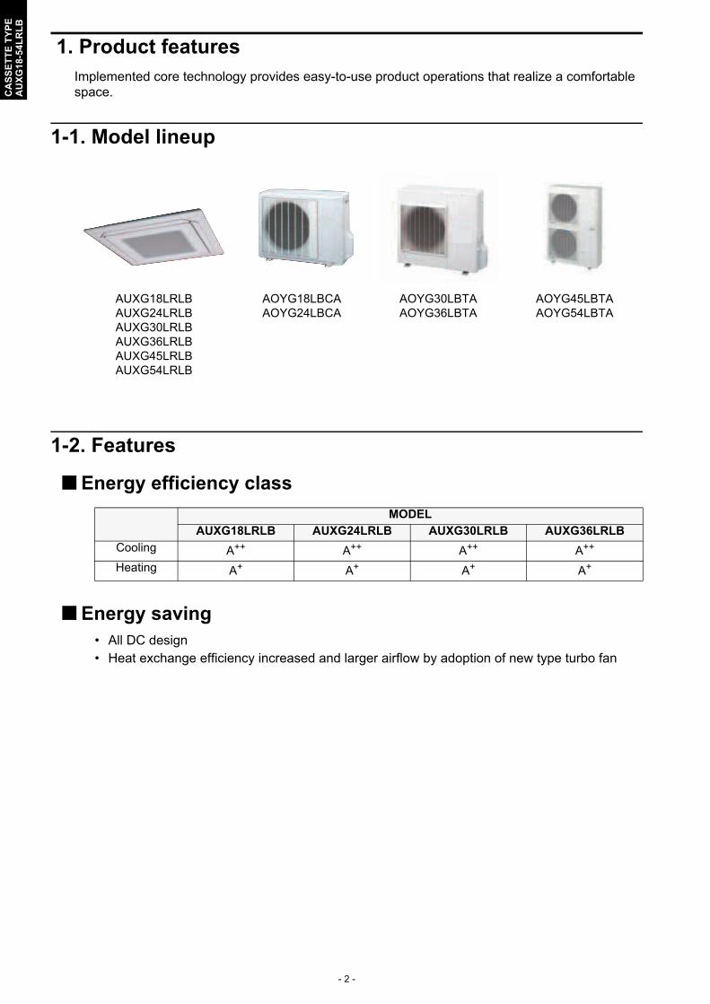
1. Product featuresImplemented core technology provides easy-to-use product operations that realize a comfortable space.
1-1. Model lineup
1-2. Features
Energy efficiency class
Energy saving• All DC design• Heat exchange efficiency increased and larger airflow by adoption of new type turbo fan
AUXG18LRLBAUXG24LRLBAUXG30LRLBAUXG36LRLBAUXG45LRLBAUXG54LRLB
AOYG18LBCAAOYG24LBCA
AOYG30LBTAAOYG36LBTA
AOYG45LBTAAOYG54LBTA
MODEL
AUXG18LRLB AUXG24LRLB AUXG30LRLB AUXG36LRLB
Cooling A++ A++ A++ A++
Heating A+ A+ A+ A+
- 3 -
CA
SS
ET
TE
TY
PE
AU
XG
18-5
4LR
LB
Advancement in comfort
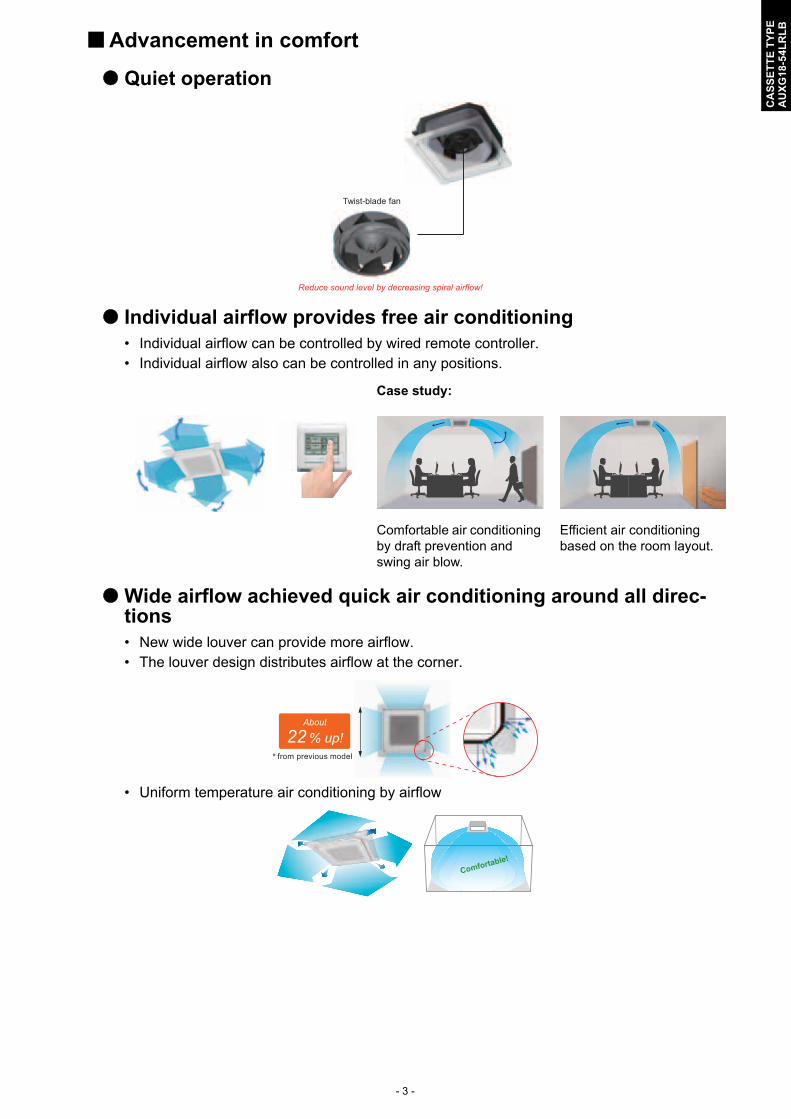
Quiet operation
Individual airflow provides free air conditioning• Individual airflow can be controlled by wired remote controller.• Individual airflow also can be controlled in any positions.
Wide airflow achieved quick air conditioning around all direc-tions• New wide louver can provide more airflow.• The louver design distributes airflow at the corner.
• Uniform temperature air conditioning by airflow
Case study:
Comfortable air conditioning by draft prevention and swing air blow.
Efficient air conditioning based on the room layout.
Twist-blade fan
Reduce sound level by decreasing spiral airflow!
* from previous model
22 % up!About
Comfortable!

- 4 -
CA
SS
ET
TE
TY
PE
AU
XG
18-5
4LR
LB
Economy operationLimits the maximum operation current, and the power consumption is cut down and the maxi-mum load is suppressed.
Improvement of installation and maintenance
High lift drain pump
Easy installationEasy setting by wired remote controller.
Time
Economy operation
Normal operationSetting
temperature
850 mmCeiling panel
- 5 -
CA
SS
ET
TE
TY
PE
AU
XG
18-5
4LR
LB
2. Wired remote controller
2-1. Features
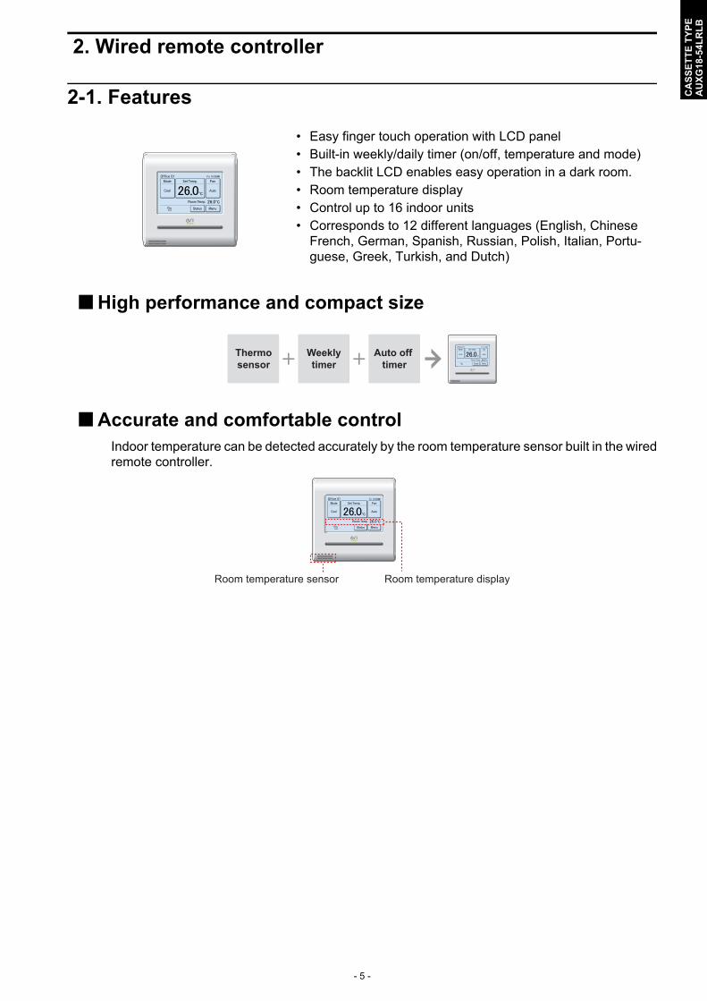
High performance and compact size
Accurate and comfortable controlIndoor temperature can be detected accurately by the room temperature sensor built in the wiredremote controller.
• Easy finger touch operation with LCD panel• Built-in weekly/daily timer (on/off, temperature and mode)• The backlit LCD enables easy operation in a dark room.• Room temperature display• Control up to 16 indoor units• Corresponds to 12 different languages (English, Chinese
French, German, Spanish, Russian, Polish, Italian, Portu-guese, Greek, Turkish, and Dutch)
Thermosensor
Weeklytimer
Auto off timer
Room temperature sensor Room temperature display

- 6 -
CA
SS
ET
TE
TY
PE
AU
XG
18-5
4LR
LB
Various energy saving control• Auto-off timer
– The indoor unit automatically turns off after the set time has passed.– The time interval for which auto-off works can be set.
• 2 schedules weekly timer– 2 schedules such as for the summer and winter can be set.– 8 setting changeable per day of week (Setting items: on/off, temperature, mode, and time)
• Set temperature auto return– The setting temperature automatically returns to the previous setting temperature.– The time range in which the set temperature can be changed is 10 to 120 minutes.
• Set temperature upper and lower limit settingThe set temperature range can be set for each operation mode (COOL, HEAT, and AUTO).
Set interval time hour (17:00 to 24:00)
Set off time (30 to 240 minutes)
17: 4200 :00
On Auto-off
Off
Example: At interval time hour (17:00 to 24:00) to prevent forgetting to turn off.
Schedule 1 (Summer schedule) Schedule 2 (Winter schedule)
26 °C
24 °C
On
8:40 11:40 17:30 20:40
Off Off Off Off
Time
25 °C
23 °C
OnSetting temp.Setting temp.
Setting example:
8:40 10:00 17:3015:30 20:40Time
Setting temp.Setting temp.
Cooling operation
24 °C
22 °C
Set temperature change Auto return
11:40 13:40Time
Settable time range10 to 120 minutes
Heating operation
25 °C
23 °C
Set temperature change Auto return
11:40 13:40Time
Settable time range10 to 120 minutes
Original temp.setting range
Lower limitsetting
During cooling30 °C
25 °C
18 °COriginal temp.setting range
Upper limitsetting
During heating30 °C
25 °C
16 °C

- 7 -
CA
SS
ET
TE
TY
PE
AU
XG
18-5
4LR
LB
Various convenient functions• Displays setting status and limitations
• Summer time display
• Child safety lock
Simplified installation
Easy maintenance
The remote controller settings can be easily checked.
Can be set easily from “Menu” screen.
Lock/unlock procedure: While touching the blank field on “Monitor” screen, push the on/off button for 4 seconds.
Use of non-polar 2-wire typeFaulty wiring can be prevented by using non-polar 2-wire.
Error history display
• Errors occur on the indoor unit or the remote controller are saved as a history.
• Maximum of 32-error incidents can be saved.
• Under Maintenance• Forced Stop• Mode Mismatch
PreviousPage
StatusR.C. Prohibition
Special State
Page 2/ 4
Monitor NextPage
• Op. Controlled• Set Temp. Limited• Energy Saving Operation• Defrost• Oil Recovery
StatusSpecial Srate
Page 3/ 4
Monitor PreviousPage
NextPage
• Human Sensor Setting• Fan Control for Energy Saving
StatusSpecial Srate
Page 4/ 4
Monitor PreviousPage
StatusAir Flow Direction
VT
Off
1
Economy
Individual
Page 1/ 4
Monitor NextPage
OK OK
non-polar2-wire
Y1 Y2 Y1 Y2
I.U. I.U.Y1Y2Y3 Y1Y2Y3
- 8 -
CA
SS
ET
TE
TY
PE
AU
XG
18-5
4LR
LB
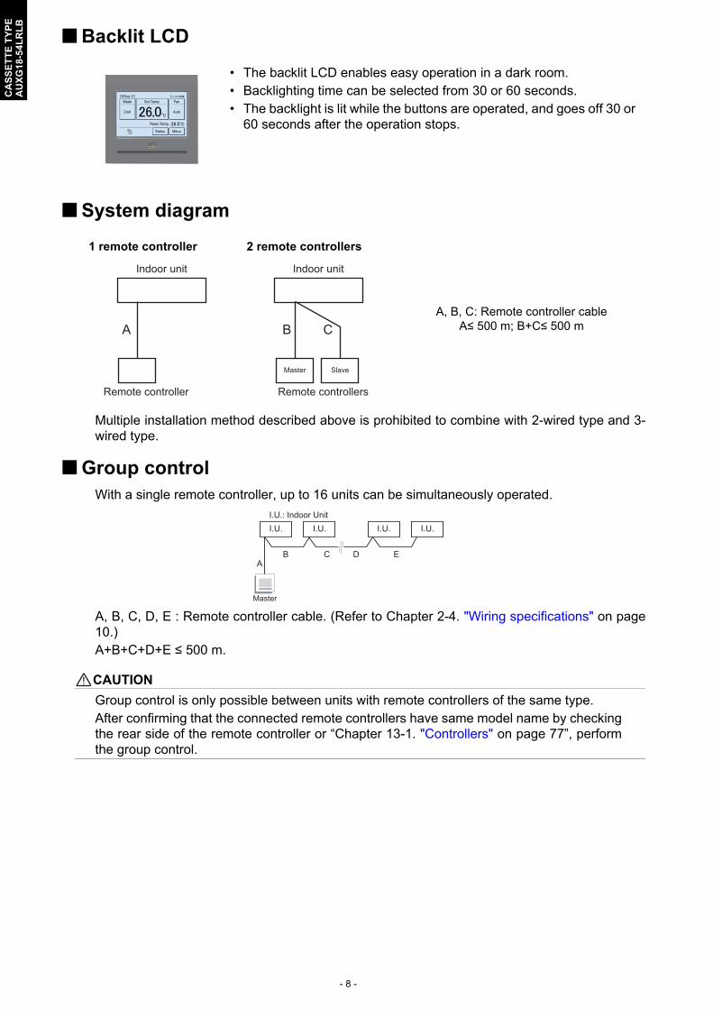
Backlit LCD
System diagram
Multiple installation method described above is prohibited to combine with 2-wired type and 3-wired type.
Group controlWith a single remote controller, up to 16 units can be simultaneously operated.
A, B, C, D, E : Remote controller cable. (Refer to Chapter 2-4. "Wiring specifications" on page10.)A+B+C+D+E ≤ 500 m.
! CAUTION
Group control is only possible between units with remote controllers of the same type.After confirming that the connected remote controllers have same model name by checkingthe rear side of the remote controller or “Chapter 13-1. "Controllers" on page 77”, performthe group control.
• The backlit LCD enables easy operation in a dark room.• Backlighting time can be selected from 30 or 60 seconds.• The backlight is lit while the buttons are operated, and goes off 30 or
60 seconds after the operation stops.
1 remote controller 2 remote controllers
A, B, C: Remote controller cableA≤ 500 m; B+C≤ 500 mA
Indoor unit
Remote controller
Master Slave
B C
Indoor unit
Remote controllers
AB C D E
I.U. I.U. I.U. I.U.
Master
I.U.: Indoor Unit
- 9 -
CA
SS
ET
TE
TY
PE
AU
XG
18-5
4LR
LB
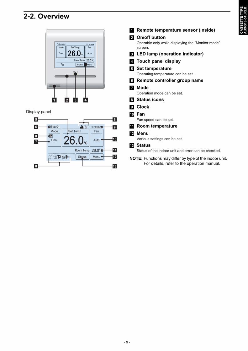
2-2. Overview
Display panel
a Remote temperature sensor (inside)
b On/off buttonOperable only while displaying the “Monitor mode” screen.
c LED lamp (operation indicator)
d Touch panel display
e Set temperatureOperating temperature can be set.
f Remote controller group name
g ModeOperation mode can be set.
h Status icons
i Clock
j FanFan speed can be set.
k Room temperature
l MenuVarious settings can be set.
m StatusStatus of the indoor unit and error can be checked.
NOTE: Functions may differ by type of the indoor unit. For details, refer to the operation manual.
a b c d
26.026.0°C°CCool Auto
Office 01Set Temp.
26.0°C26.0°C
Mode
MenuStatus
FanFri 10:00AM
Room Temp.
e
f
h
h
g
h
i
j
l
m
k

- 10 -
CA
SS
ET
TE
TY
PE
AU
XG
18-5
4LR
LB
2-3. SpecificationsDimensions and other specifications on the wired remote controller are as follows.
2-4. Wiring specifications
NOTE: Use shielded cable (locally purchased) in accordance with the regional cable standard.
Display 3.8-inch FSTN LCD (255 × 160 dots) with touch panel
Dimensions (H × W × D) mm 120 × 120 × 20.4
Weight g 220
Input voltage V DC 12
Power consumption W Max. 0.3
Usage temperature range °C 0 to 40
Usage humidity range % 20 to 90 (no condensation)
Storage temperature range °C -10 to 60
Storage humidity range % 20 to 90 (no condensation)
Use Cable size Wire type Remarks
Remote controller cable 0.33 to 1.25 mm2 Non-polar 2-core Use sheathed PVC cable.
20.4120
120
[Unit : mm]

- 11 -
CA
SS
ET
TE
TY
PE
AU
XG
18-5
4LR
LB
3. Specifications
3-1. Models: AUXG18LRLB and AUXG24LRLB
TypeCassette
Inverter heat pump
Model name AUXG18LRLB AUXG24LRLB
Power supply 230 V ~ 50 Hz
Available voltage range 198—264 V
Capacity
Cooling
RatedkW 5.2 6.8
Btu/h 17,700 23,200
Min.—Max.kW 0.90—6.50 0.90—8.00
Btu/h 3,100—22,200 3,100—27,300
Heating
RatedkW 6.0 7.8
Btu/h 20,500 26,600
Min.—Max.kW 0.90—8.00 0.90—9.10
Btu/h 3,100—27,300 3,100—31,000
Input power
CoolingRated
kW
1.42 2,16
Max. 2.28 3.08
HeatingRated 1.50 2.18
Max. 3.08 4.22
Fan
HIGH
W
16 21
MED 12 16
LOW 11 13
QUIET 7 9
CurrentCooling
Rated A6.2 9.5
Heating 6.6 9.6
Power factorCooling
%99.6 98.9
Heating 98.8 98.7
EER CoolingkW/kW
3.66 3.15
COP Heating 4.00 3.58
Moisture removal L/h (pints/h) 2.2 (3.9) 2.7 (4.8)
Maximum operating current *1Cooling
A10.0 13.5
Heating 13.5 18.5
Fan
Airflow rate
Cooling
HIGH
m3/h
1,050 1,150
MED 960 1,050
LOW 900 980
QUIET 780 870
Heating
HIGH 1,050 1,150
MED 960 1,050
LOW 900 980
QUIET 780 870
Type × Q'ty Turbo fan × 1
Motor output W 81
Sound pressure level *2
Cooling
HIGH
dB (A)
33 35
MED 32 33
LOW 31 32
QUIET 28 29
Heating
HIGH 33 35
MED 32 33
LOW 31 32
QUIET 28 29
Sound power levelCooling
HIGH dB (A)47 49
Heating 47 49
Heat exchanger type
Dimensions (H × W × D)mm
210 × 2,127 × 13.3210 × 2,061 × 13.3
Fin pitch 1.2
Rows × Stages 2 × 10
Pipe type Copper tube
Fin type Aluminum
Dimensions(H × W × D)
Netmm
246 × 840 × 840
Gross 298 × 960 × 950
WeightNet
kg24
Gross 29
Connection pipeSize
Liquidmm (in)
Ø 6.35 (Ø 1/4)
Gas Ø 12.70 (Ø 1/2) Ø 15.88 (Ø 5/8)
Method Flare
Drain hoseMaterial PVC(VP25)
Size mm Ø 25 (I.D.), Ø 32 (O.D.)
Operation rangeCooling
°C 18 to 32
%RH 80 or less
Heating °C 16 to 30
Cassette grille
Material PS
ColorWhite
Approximate color of MUNSELL N 9.25/
Dimensions(H × W × D)
Netmm
53 × 950 × 950
Gross 110 × 1,000 × 1,010
WeightNet
kg6.0
Gross 10.5

- 12 -
CA
SS
ET
TE
TY
PE
AU
XG
18-5
4LR
LB
Remote controller type Wired (Wireless [option])
NOTES: Specifications are based on the following conditions:
–Cooling: Indoor temperature of 27 °CDB/19 °CWB, and outdoor temperature of 35 °CDB/24 °CWB.–Heating: Indoor temperature of 20 °CDB/15 °CWB, and outdoor temperature of 7 °CDB/6 °CWB.–Pipe length: 5 m, Height difference: 0 m. (Between outdoor unit and indoor unit.)
Protective function might work when using it outside the operation range.*1: Maximum current:
–The maximum value when operated within the operation range.–The total current of indoor unit and outdoor unit.
*2: Sound pressure level:–Measured values in manufacturer’s anechoic chamber.–Because of the surrounding sound environment, the sound levels measured in actual installation conditions might be higher than the specified values here.
Model name AUXG18LRLB AUXG24LRLB
Energy efficiency classCooling A++ A++
Heating (Average) A+ A+
PdesignCooling
kW5.2 (35°C) 6.8 (35°C)
Heating (Average) 4.3 (-10°C) 6.0 (-10°C)
SEER CoolingkWh/kWh
7.05 6.60
SCOP Heating (Average) 4.40 4.20
Annual energy consumptionQCE
kWh/a258 361
QHE (Average) 1,367 1,999
Sound power levelCooling
HIGH dB (A)47 49
Heating 47 49
TypeCassette
Inverter heat pump
Model name AUXG18LRLB AUXG24LRLB
- 13 -
CA
SS
ET
TE
TY
PE
AU
XG
18-5
4LR
LB
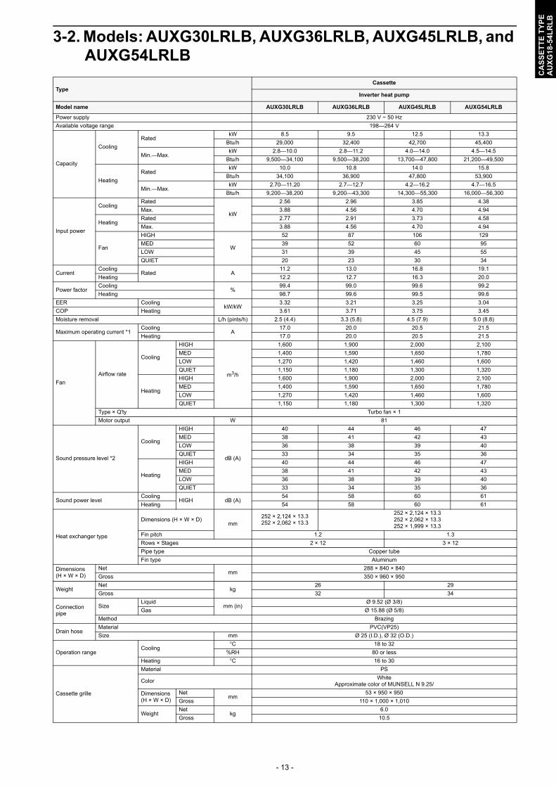
3-2. Models: AUXG30LRLB, AUXG36LRLB, AUXG45LRLB, and AUXG54LRLB
TypeCassette
Inverter heat pump
Model name AUXG30LRLB AUXG36LRLB AUXG45LRLB AUXG54LRLB
Power supply 230 V ~ 50 Hz
Available voltage range 198—264 V
Capacity
Cooling
RatedkW 8.5 9.5 12.5 13.3
Btu/h 29,000 32,400 42,700 45,400
Min.—Max.kW 2.8—10.0 2.8—11.2 4.0—14.0 4.5—14.5
Btu/h 9,500—34,100 9,500—38,200 13,700—47,800 21,200—49,500
Heating
RatedkW 10.0 10.8 14.0 15.8
Btu/h 34,100 36,900 47,800 53,900
Min.—Max.kW 2.70—11.20 2.7—12.7 4.2—16.2 4.7—16.5
Btu/h 9,200—38,200 9,200—43,300 14,300—55,300 16,000—56,300
Input power
CoolingRated
kW
2.56 2.96 3.85 4.38
Max. 3.88 4.56 4.70 4.94
HeatingRated 2.77 2.91 3.73 4.58
Max. 3.88 4.56 4.70 4.94
Fan
HIGH
W
52 87 106 129
MED 39 52 60 95
LOW 31 39 45 55
QUIET 20 23 30 34
CurrentCooling
Rated A11.2 13.0 16.8 19.1
Heating 12.2 12.7 16.3 20.0
Power factorCooling
%99.4 99.0 99.6 99.2
Heating 98.7 99.6 99.5 99.6
EER CoolingkW/kW
3.32 3.21 3.25 3.04
COP Heating 3.61 3.71 3.75 3.45
Moisture removal L/h (pints/h) 2.5 (4.4) 3.3 (5.8) 4.5 (7.9) 5.0 (8.8)
Maximum operating current *1Cooling
A17.0 20.0 20.5 21.5
Heating 17.0 20.0 20.5 21.5
Fan
Airflow rate
Cooling
HIGH
m3/h
1,600 1,900 2,000 2,100
MED 1,400 1,590 1,650 1,780
LOW 1,270 1,420 1,460 1,600
QUIET 1,150 1,180 1,300 1,320
Heating
HIGH 1,600 1,900 2,000 2,100
MED 1,400 1,590 1,650 1,780
LOW 1,270 1,420 1,460 1,600
QUIET 1,150 1,180 1,300 1,320
Type × Q'ty Turbo fan × 1
Motor output W 81
Sound pressure level *2
Cooling
HIGH
dB (A)
40 44 46 47
MED 38 41 42 43
LOW 36 38 39 40
QUIET 33 34 35 36
Heating
HIGH 40 44 46 47
MED 38 41 42 43
LOW 36 38 39 40
QUIET 33 34 35 36
Sound power levelCooling
HIGH dB (A)54 58 60 61
Heating 54 58 60 61
Heat exchanger type
Dimensions (H × W × D)mm
252 × 2,124 × 13.3252 × 2,062 × 13.3
252 × 2,124 × 13.3252 × 2,062 × 13.3252 × 1,999 × 13.3
Fin pitch 1.2 1.3
Rows × Stages 2 × 12 3 × 12
Pipe type Copper tube
Fin type Aluminum
Dimensions(H × W × D)
Netmm
288 × 840 × 840
Gross 350 × 960 × 950
WeightNet
kg26 29
Gross 32 34
Connection pipe
SizeLiquid
mm (in)Ø 9.52 (Ø 3/8)
Gas Ø 15.88 (Ø 5/8)
Method Brazing
Drain hoseMaterial PVC(VP25)
Size mm Ø 25 (I.D.), Ø 32 (O.D.)
Operation rangeCooling
°C 18 to 32
%RH 80 or less
Heating °C 16 to 30
Cassette grille
Material PS
ColorWhite
Approximate color of MUNSELL N 9.25/
Dimensions(H × W × D)
Netmm
53 × 950 × 950
Gross 110 × 1,000 × 1,010
WeightNet
kg6.0
Gross 10.5
- 14 -
CA
SS
ET
TE
TY
PE
AU
XG
18-5
4LR
LB
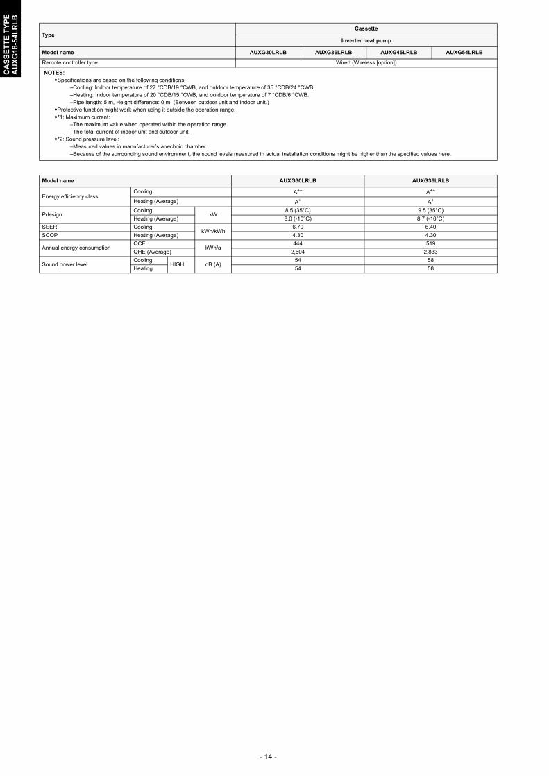
Remote controller type Wired (Wireless [option])
NOTES: Specifications are based on the following conditions:
–Cooling: Indoor temperature of 27 °CDB/19 °CWB, and outdoor temperature of 35 °CDB/24 °CWB.–Heating: Indoor temperature of 20 °CDB/15 °CWB, and outdoor temperature of 7 °CDB/6 °CWB.–Pipe length: 5 m, Height difference: 0 m. (Between outdoor unit and indoor unit.)
Protective function might work when using it outside the operation range.*1: Maximum current:
–The maximum value when operated within the operation range.–The total current of indoor unit and outdoor unit.
*2: Sound pressure level:–Measured values in manufacturer’s anechoic chamber.–Because of the surrounding sound environment, the sound levels measured in actual installation conditions might be higher than the specified values here.
Model name AUXG30LRLB AUXG36LRLB
Energy efficiency classCooling A++ A++
Heating (Average) A+ A+
PdesignCooling
kW8.5 (35°C) 9.5 (35°C)
Heating (Average) 8.0 (-10°C) 8.7 (-10°C)
SEER CoolingkWh/kWh
6.70 6.40
SCOP Heating (Average) 4.30 4.30
Annual energy consumptionQCE
kWh/a444 519
QHE (Average) 2,604 2,833
Sound power levelCooling
HIGH dB (A)54 58
Heating 54 58
TypeCassette
Inverter heat pump
Model name AUXG30LRLB AUXG36LRLB AUXG45LRLB AUXG54LRLB

- 15 -
CA
SS
ET
TE
TY
PE
AU
XG
18-5
4LR
LB
4. Dimensions
4-1. Models: AUXG18LRLB and AUXG24LRLB
Ceiling opening and hanging bolt pitch
Refrigerant piping and drain piping positions
246
256
401014
0–14
5
50–1
00
950 (Panel frame)
20–45 20–45
50
80
130
130
130
200
840 (Body frame)
796 (Hanging bolt pitch)
768
(Han
ging
bol
t pitc
h)
860–910 (Ceiling opening)
950
(Pan
el fr
ame)
840
(Bod
y fra
me)
860–
910
(Cei
ling
open
ing)
20–4
520
–45
Unit: mm
45293342
140 18
0
200
Drain pipe(Connect the attached drain hose)
Unit: mm

- 16 -
CA
SS
ET
TE
TY
PE
AU
XG
18-5
4LR
LB
Airflow split-flow duct and fresh-air inlet positions
114 95
3.2 hole
3.2 hole
280
352
100
8383
90
100
16
3 163
Airflow split-flow duct connecting port
Airfl
ow s
plit-
flow
duc
t con
nect
ing
port
Airfl
ow s
plit-
flow
duc
t con
nect
ing
port
Fresh air inlet position
Fresh air inlet position
Drain pipeRefrigerant pipe
Detailed diagram of branched duct connecting port (4 sides)
Knockout hole pitch Cut out
Cut out
Airflow split-flow duct connecting port
10
4
Unit: mm

- 17 -
CA
SS
ET
TE
TY
PE
AU
XG
18-5
4LR
LB
4-2. Models: AUXG30LRLB, AUXG36LRLB, AUXG45LRLB, and AUXG54LRLB
Ceiling opening and hanging bolt pitch
Refrigerant piping and drain piping positions
288
298
401020
0–20
5
50–1
00
950 (Panel frame)
20–45 20–45
50
80
130
130
130
200
840 (Body frame)
796 (Hanging bolt pitch)
768
(Han
ging
bol
t pitc
h)
860–910 (Ceiling opening)
950
(Pan
el fr
ame)
840
(Bod
y fra
me)
860–
910
(Cei
ling
open
ing)
20–4
520
–45
Unit: mm
45293342
140 18
0
200
Drain pipe(Connect the attached drain hose)
Unit: mm
- 18 -
CA
SS
ET
TE
TY
PE
AU
XG
18-5
4LR
LB
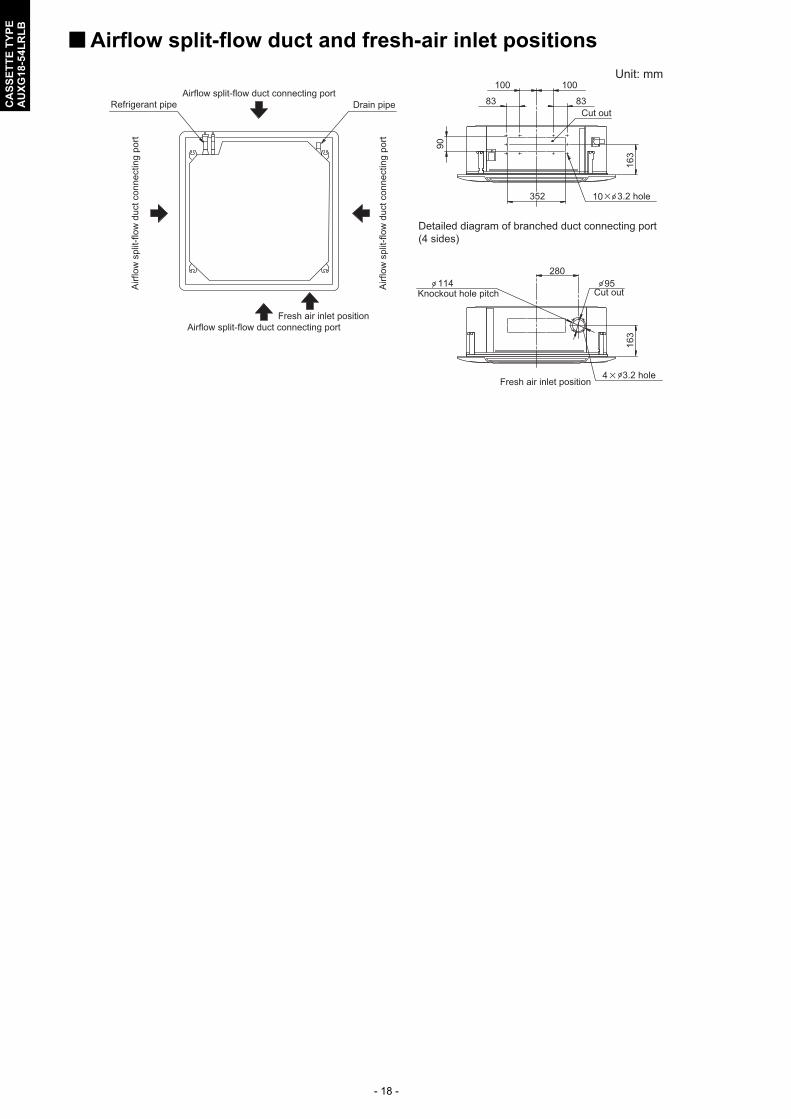
Airflow split-flow duct and fresh-air inlet positions
114 95
3.2 hole
3.2 hole
280
352
100
8383
90
100
16
3 163
Airflow split-flow duct connecting port
Airf
low
spl
it-flo
w d
uct c
onne
ctin
g po
rt
Airf
low
spl
it-flo
w d
uct c
onne
ctin
g po
rt
Fresh air inlet position
Fresh air inlet position
Drain pipeRefrigerant pipe
Detailed diagram of branched duct connecting port (4 sides)
Knockout hole pitch Cut out
Cut out
Airflow split-flow duct connecting port
10
4
Unit: mm
- 19 -
CA
SS
ET
TE
TY
PE
AU
XG
18-5
4LR
LB
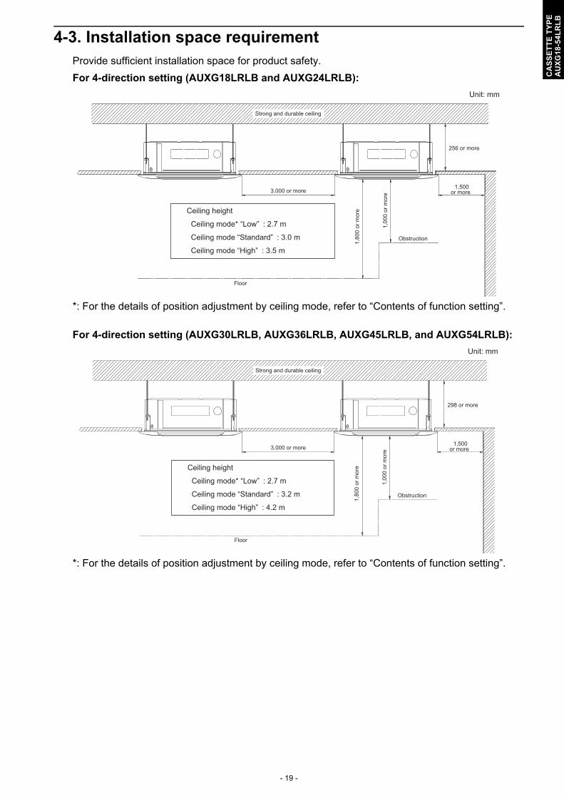
4-3. Installation space requirementProvide sufficient installation space for product safety.
For 4-direction setting (AUXG18LRLB and AUXG24LRLB):
*: For the details of position adjustment by ceiling mode, refer to “Contents of function setting”.
For 4-direction setting (AUXG30LRLB, AUXG36LRLB, AUXG45LRLB, and AUXG54LRLB):
*: For the details of position adjustment by ceiling mode, refer to “Contents of function setting”.
1,500or more
1,00
0 or
mor
e
1,80
0 or
mor
e
Obstruction
3,000 or more
Strong and durable ceiling
Floor
Ceiling height
Ceiling mode* “Low” : 2.7 m
Ceiling mode “Standard” : 3.0 m
Ceiling mode “High” : 3.5 m
256 or more
Unit: mm
1,500or more
1,00
0 or
mor
e
1,80
0 or
mor
e
Obstruction
3,000 or more
Strong and durable ceiling
Floor
Ceiling height
Ceiling mode* “Low” : 2.7 m
Ceiling mode “Standard” : 3.2 m
Ceiling mode “High” : 4.2 m
298 or more
Unit: mm
- 20 -
CA
SS
ET
TE
TY
PE
AU
XG
18-5
4LR
LB
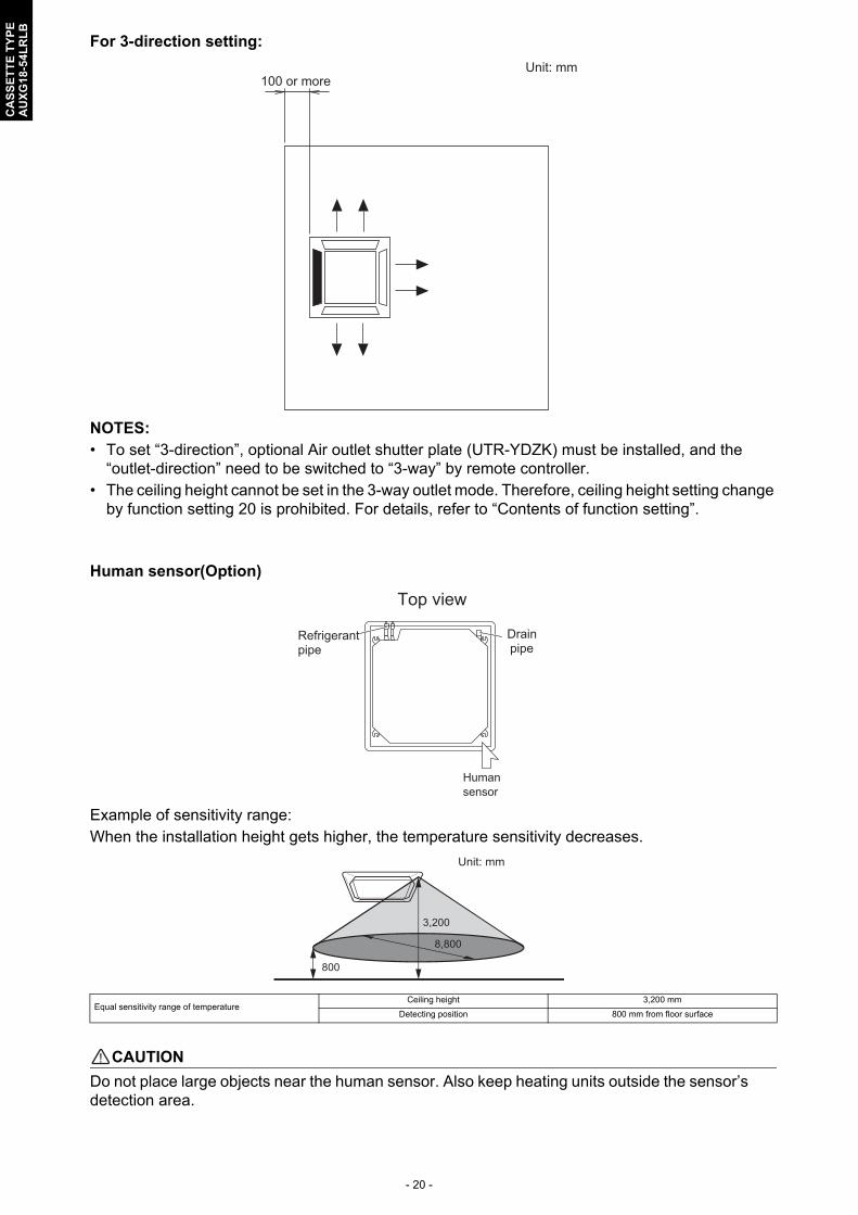
For 3-direction setting:
NOTES: • To set “3-direction”, optional Air outlet shutter plate (UTR-YDZK) must be installed, and the
“outlet-direction” need to be switched to “3-way” by remote controller.• The ceiling height cannot be set in the 3-way outlet mode. Therefore, ceiling height setting change
by function setting 20 is prohibited. For details, refer to “Contents of function setting”.
Human sensor(Option)
Example of sensitivity range:When the installation height gets higher, the temperature sensitivity decreases.
! CAUTION
Do not place large objects near the human sensor. Also keep heating units outside the sensor’sdetection area.
Equal sensitivity range of temperatureCeiling height 3,200 mm
Detecting position 800 mm from floor surface
100 or moreUnit: mm
Drain pipe
Refrigerant pipe
Human sensor
Top view
3,200
800
8,800
Unit: mm
- 21 -
CA
SS
ET
TE
TY
PE
AU
XG
18-5
4LR
LB
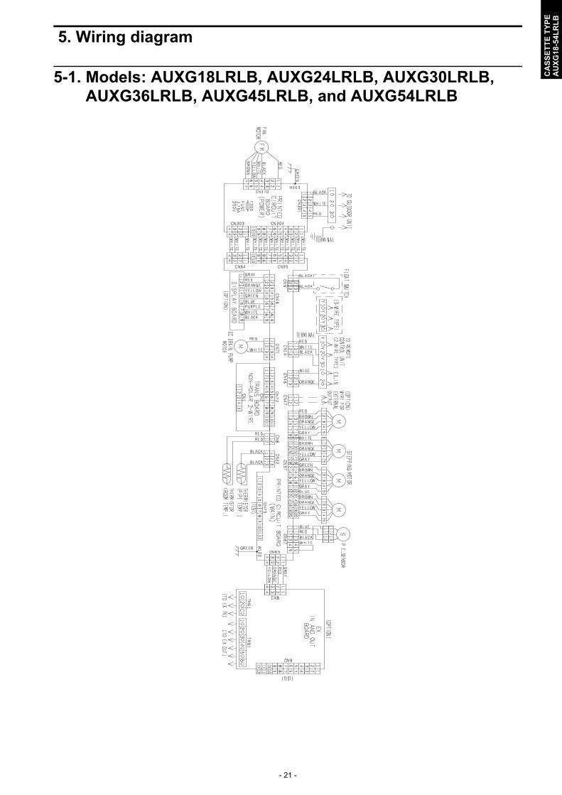
5. Wiring diagram
5-1. Models: AUXG18LRLB, AUXG24LRLB, AUXG30LRLB, AUXG36LRLB, AUXG45LRLB, and AUXG54LRLB
- 22 -
CA
SS
ET
TE
TY
PE
AU
XG
18-5
4LR
LB
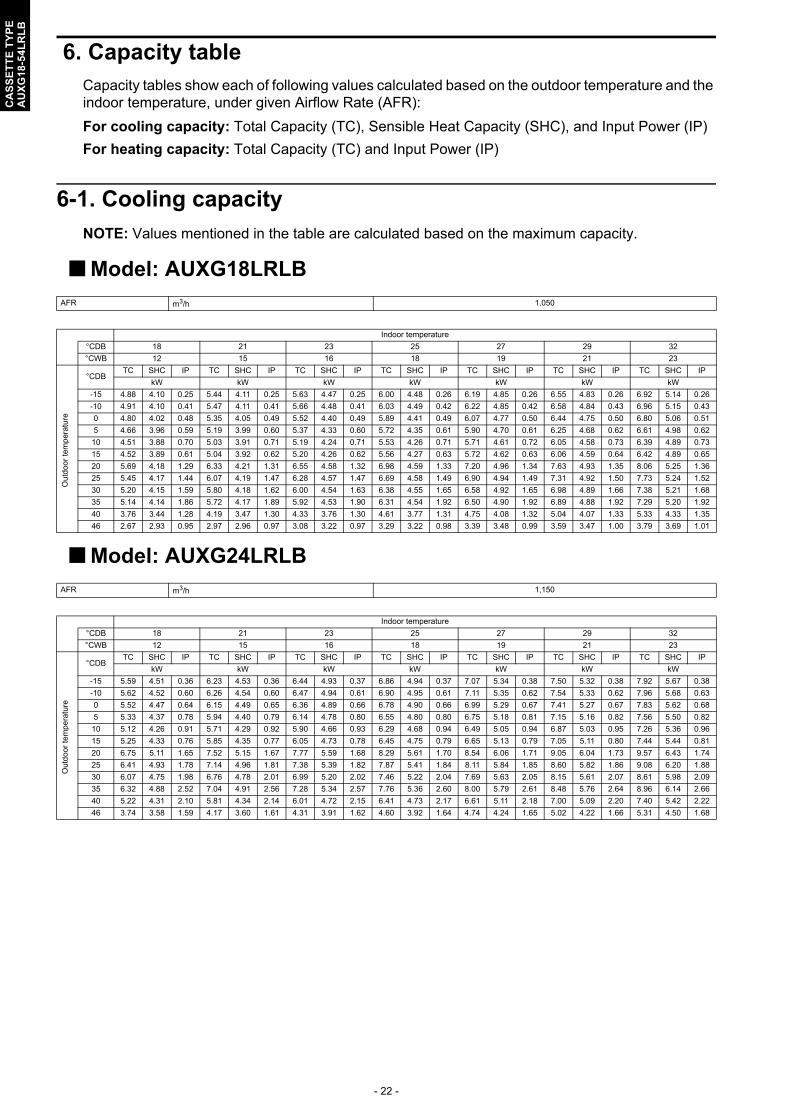
6. Capacity tableCapacity tables show each of following values calculated based on the outdoor temperature and the indoor temperature, under given Airflow Rate (AFR):
For cooling capacity: Total Capacity (TC), Sensible Heat Capacity (SHC), and Input Power (IP)
For heating capacity: Total Capacity (TC) and Input Power (IP)
6-1. Cooling capacity
NOTE: Values mentioned in the table are calculated based on the maximum capacity.
Model: AUXG18LRLB
Model: AUXG24LRLB
AFR m3/h 1,050
Indoor temperature
°CDB 18 21 23 25 27 29 32
°CWB 12 15 16 18 19 21 23
Ou
tdoo
r te
mp
erat
ure
°CDBTC SHC IP TC SHC IP TC SHC IP TC SHC IP TC SHC IP TC SHC IP TC SHC IP
kW kW kW kW kW kW kW
-15 4.88 4.10 0.25 5.44 4.11 0.25 5.63 4.47 0.25 6.00 4.48 0.26 6.19 4.85 0.26 6.55 4.83 0.26 6.92 5.14 0.26
-10 4.91 4.10 0.41 5.47 4.11 0.41 5.66 4.48 0.41 6.03 4.49 0.42 6.22 4.85 0.42 6.58 4.84 0.43 6.96 5.15 0.43
0 4.80 4.02 0.48 5.35 4.05 0.49 5.52 4.40 0.49 5.89 4.41 0.49 6.07 4.77 0.50 6.44 4.75 0.50 6.80 5.06 0.51
5 4.66 3.96 0.59 5.19 3.99 0.60 5.37 4.33 0.60 5.72 4.35 0.61 5.90 4.70 0.61 6.25 4.68 0.62 6.61 4.98 0.62
10 4.51 3.88 0.70 5.03 3.91 0.71 5.19 4.24 0.71 5.53 4.26 0.71 5.71 4.61 0.72 6.05 4.58 0.73 6.39 4.89 0.73
15 4.52 3.89 0.61 5.04 3.92 0.62 5.20 4.26 0.62 5.56 4.27 0.63 5.72 4.62 0.63 6.06 4.59 0.64 6.42 4.89 0.65
20 5.69 4.18 1.29 6.33 4.21 1.31 6.55 4.58 1.32 6.98 4.59 1.33 7.20 4.96 1.34 7.63 4.93 1.35 8.06 5.25 1.36
25 5.45 4.17 1.44 6.07 4.19 1.47 6.28 4.57 1.47 6.69 4.58 1.49 6.90 4.94 1.49 7.31 4.92 1.50 7.73 5.24 1.52
30 5.20 4.15 1.59 5.80 4.18 1.62 6.00 4.54 1.63 6.38 4.55 1.65 6.58 4.92 1.65 6.98 4.89 1.66 7.38 5.21 1.68
35 5.14 4.14 1.86 5.72 4.17 1.89 5.92 4.53 1.90 6.31 4.54 1.92 6.50 4.90 1.92 6.89 4.88 1.92 7.29 5.20 1.92
40 3.76 3.44 1.28 4.19 3.47 1.30 4.33 3.76 1.30 4.61 3.77 1.31 4.75 4.08 1.32 5.04 4.07 1.33 5.33 4.33 1.35
46 2.67 2.93 0.95 2.97 2.96 0.97 3.08 3.22 0.97 3.29 3.22 0.98 3.39 3.48 0.99 3.59 3.47 1.00 3.79 3.69 1.01
AFR m3/h 1,150
Indoor temperature
°CDB 18 21 23 25 27 29 32
°CWB 12 15 16 18 19 21 23
Out
do
or t
em
pera
ture
°CDBTC SHC IP TC SHC IP TC SHC IP TC SHC IP TC SHC IP TC SHC IP TC SHC IP
kW kW kW kW kW kW kW
-15 5.59 4.51 0.36 6.23 4.53 0.36 6.44 4.93 0.37 6.86 4.94 0.37 7.07 5.34 0.38 7.50 5.32 0.38 7.92 5.67 0.38
-10 5.62 4.52 0.60 6.26 4.54 0.60 6.47 4.94 0.61 6.90 4.95 0.61 7.11 5.35 0.62 7.54 5.33 0.62 7.96 5.68 0.63
0 5.52 4.47 0.64 6.15 4.49 0.65 6.36 4.89 0.66 6.78 4.90 0.66 6.99 5.29 0.67 7.41 5.27 0.67 7.83 5.62 0.68
5 5.33 4.37 0.78 5.94 4.40 0.79 6.14 4.78 0.80 6.55 4.80 0.80 6.75 5.18 0.81 7.15 5.16 0.82 7.56 5.50 0.82
10 5.12 4.26 0.91 5.71 4.29 0.92 5.90 4.66 0.93 6.29 4.68 0.94 6.49 5.05 0.94 6.87 5.03 0.95 7.26 5.36 0.96
15 5.25 4.33 0.76 5.85 4.35 0.77 6.05 4.73 0.78 6.45 4.75 0.79 6.65 5.13 0.79 7.05 5.11 0.80 7.44 5.44 0.81
20 6.75 5.11 1.65 7.52 5.15 1.67 7.77 5.59 1.68 8.29 5.61 1.70 8.54 6.06 1.71 9.05 6.04 1.73 9.57 6.43 1.74
25 6.41 4.93 1.78 7.14 4.96 1.81 7.38 5.39 1.82 7.87 5.41 1.84 8.11 5.84 1.85 8.60 5.82 1.86 9.08 6.20 1.88
30 6.07 4.75 1.98 6.76 4.78 2.01 6.99 5.20 2.02 7.46 5.22 2.04 7.69 5.63 2.05 8.15 5.61 2.07 8.61 5.98 2.09
35 6.32 4.88 2.52 7.04 4.91 2.56 7.28 5.34 2.57 7.76 5.36 2.60 8.00 5.79 2.61 8.48 5.76 2.64 8.96 6.14 2.66
40 5.22 4.31 2.10 5.81 4.34 2.14 6.01 4.72 2.15 6.41 4.73 2.17 6.61 5.11 2.18 7.00 5.09 2.20 7.40 5.42 2.22
46 3.74 3.58 1.59 4.17 3.60 1.61 4.31 3.91 1.62 4.60 3.92 1.64 4.74 4.24 1.65 5.02 4.22 1.66 5.31 4.50 1.68
- 23 -
CA
SS
ET
TE
TY
PE
AU
XG
18-5
4LR
LB
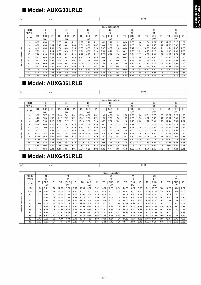
Model: AUXG30LRLB
Model: AUXG36LRLB
Model: AUXG45LRLB
AFR m3/h 1,600
Indoor temperature
°CDB 18 21 23 25 27 29 32
°CWB 12 15 16 18 19 21 23
Out
doo
r te
mp
erat
ure
°CDBTC SHC IP TC SHC IP TC SHC IP TC SHC IP TC SHC IP TC SHC IP TC SHC IP
kW kW kW kW kW kW kW
-15 8.67 6.58 1.20 9.66 6.62 1.22 9.99 7.20 1.22 10.65 7.22 1.22 10.98 7.80 1.24 11.64 7.77 1.25 12.29 8.27 1.27
-10 8.52 6.38 1.64 9.49 6.42 1.66 9.81 6.98 1.67 10.46 7.00 1.69 10.79 7.56 1.70 11.44 7.53 1.72 12.08 8.02 1.73
0 8.12 6.26 2.11 9.04 6.30 2.15 9.35 6.85 2.16 9.97 6.87 2.18 10.28 7.42 2.19 10.90 7.39 2.21 11.51 7.87 2.23
5 7.99 6.11 2.14 8.90 6.14 2.17 9.21 6.68 2.19 9.81 6.70 2.21 10.12 7.23 2.22 10.73 7.20 2.24 11.33 7.68 2.26
10 7.96 6.19 2.19 8.87 6.23 2.23 9.17 6.77 2.24 9.77 6.79 2.26 10.07 7.34 2.27 10.67 7.31 2.29 11.28 7.79 2.32
15 8.63 6.48 2.41 9.62 6.52 2.45 9.95 7.09 2.46 10.60 7.11 2.49 10.93 7.68 2.50 11.59 7.65 2.53 12.24 8.14 2.55
20 9.82 7.03 2.97 10.94 7.07 3.01 11.31 7.69 3.03 12.06 7.71 3.06 12.43 8.33 3.08 13.18 8.30 3.11 13.92 8.84 3.14
25 9.48 6.89 3.31 10.56 6.93 3.36 10.92 7.53 3.38 11.64 7.56 3.41 12.00 8.16 3.43 12.72 8.13 3.46 13.44 8.66 3.50
30 8.81 6.70 3.35 9.81 6.74 3.39 10.15 7.32 3.41 10.81 7.35 3.44 11.15 7.93 3.46 11.82 7.90 3.50 12.49 8.42 3.53
35 7.90 6.12 3.35 8.80 6.16 3.40 9.10 6.69 3.42 9.70 6.71 3.45 10.00 7.25 3.47 10.60 7.22 3.51 11.20 7.69 3.54
40 6.16 5.13 2.94 6.86 5.16 2.99 7.09 5.61 3.00 7.56 5.63 3.04 7.80 6.08 3.05 8.27 6.06 3.08 8.73 6.45 3.11
46 5.44 4.92 2.91 6.06 4.95 2.96 6.27 5.39 2.97 6.68 5.40 3.00 6.89 5.83 3.02 7.30 5.81 3.05 7.71 6.19 3.08
AFR m3/h 1,900
Indoor temperature
°CDB 18 21 23 25 27 29 32
°CWB 12 15 16 18 19 21 23
Ou
tdo
or t
em
pera
ture
°CDBTC SHC IP TC SHC IP TC SHC IP TC SHC IP TC SHC IP TC SHC IP TC SHC IP
kW kW kW kW kW kW kW
-15 9.33 7.37 1.29 10.39 7.41 1.31 10.74 8.06 1.32 11.45 8.08 1.33 11.80 8.73 1.34 12.51 8.70 1.35 13.22 9.26 1.36
-10 9.22 7.23 1.69 10.27 7.27 1.71 10.62 7.90 1.72 11.32 7.93 1.74 11.67 8.56 1.75 12.37 8.53 1.77 13.07 9.08 1.78
0 8.77 7.13 2.18 9.77 7.17 2.22 10.10 7.80 2.23 10.77 7.82 2.25 11.10 8.45 2.26 11.77 8.41 2.29 12.44 8.96 2.31
5 8.69 6.98 2.25 9.68 7.02 2.28 10.01 7.64 2.29 10.67 7.66 2.32 11.00 8.27 2.33 11.66 8.24 2.35 12.32 8.78 2.38
10 8.62 7.06 2.25 9.60 7.10 2.29 9.93 7.72 2.30 10.58 7.75 2.32 10.91 8.37 2.34 11.56 8.33 2.36 12.22 8.88 2.38
15 9.17 7.17 2.42 10.21 7.22 2.46 10.56 7.85 2.47 11.25 7.87 2.50 11.60 8.50 2.51 12.30 8.47 2.54 13.00 9.02 2.56
20 10.70 7.92 2.99 11.92 7.97 3.03 12.33 8.66 3.05 13.14 8.69 3.08 13.54 9.39 3.10 14.36 9.35 3.13 15.17 9.96 3.16
25 10.64 8.02 3.32 11.86 8.06 3.38 12.26 8.77 3.39 13.07 8.79 3.43 13.47 9.50 3.45 14.28 9.46 3.48 15.09 10.08 3.51
30 10.24 7.76 4.05 11.40 7.81 4.11 11.79 8.49 4.13 12.57 8.51 4.17 12.96 9.19 4.19 13.73 9.16 4.24 14.51 9.75 4.28
35 8.85 6.78 4.03 9.86 6.82 4.10 10.19 7.42 4.12 10.86 7.44 4.16 11.20 8.04 4.18 11.87 8.01 4.22 12.54 8.53 4.27
40 6.80 5.96 3.09 7.58 6.00 3.14 7.84 6.52 3.16 8.35 6.54 3.19 8.61 7.07 3.20 9.13 7.04 3.24 9.65 7.50 3.27
46 6.11 5.84 2.96 6.81 5.87 3.01 7.04 6.39 3.02 7.50 6.41 3.05 7.74 6.92 3.07 8.20 6.89 3.10 8.67 7.34 3.13
AFR m3/h 2,000
Indoor temperature
°CDB 18 21 23 25 27 29 32
°CWB 12 15 16 18 19 21 23
Ou
tdo
or
tem
per
atu
re
°CDBTC SHC IP TC SHC IP TC SHC IP TC SHC IP TC SHC IP TC SHC IP TC SHC IP
kW kW kW kW kW kW kW
-15 11.34 8.71 2.56 12.63 8.76 2.60 13.06 9.52 2.62 13.92 9.55 2.64 14.35 10.32 2.66 15.21 10.28 2.68 16.07 10.95 2.71
-10 11.44 8.70 2.46 12.74 8.75 2.50 13.17 9.51 2.51 14.04 9.55 2.54 14.48 10.31 2.55 15.35 10.27 2.58 16.21 10.94 2.60
0 11.55 8.77 2.23 12.87 8.83 2.26 13.31 9.60 2.28 14.18 9.63 2.30 14.62 10.40 2.31 15.50 10.35 2.33 16.38 11.03 2.36
5 11.37 8.78 2.30 12.67 8.84 2.34 13.10 9.61 2.35 13.97 9.64 2.37 14.40 10.41 2.39 15.26 10.37 2.41 16.12 11.04 2.43
10 11.11 8.78 2.49 12.37 8.83 2.53 12.79 9.60 2.54 13.64 9.63 2.57 14.06 10.40 2.58 14.90 10.36 2.61 15.74 11.04 2.63
15 10.84 8.68 2.69 12.07 8.74 2.73 12.48 9.50 2.74 13.31 9.53 2.77 13.72 10.29 2.78 14.54 10.25 2.81 15.37 10.92 2.84
20 11.22 8.69 3.15 12.49 8.74 3.20 12.92 9.50 3.22 13.77 9.53 3.25 14.20 10.29 3.27 15.05 10.25 3.30 15.90 10.92 3.33
25 11.10 8.78 3.36 12.36 8.83 3.41 12.79 9.60 3.43 13.63 9.63 3.46 14.05 10.40 3.48 14.89 10.36 3.51 15.74 11.03 3.55
30 11.34 8.84 4.27 12.63 8.89 4.34 13.06 9.67 4.36 13.92 9.70 4.41 14.35 10.48 4.43 15.21 10.43 4.43 16.07 11.11 4.43
35 11.06 8.82 4.53 12.32 8.87 4.60 12.74 9.64 4.62 13.58 9.68 4.67 14.00 10.45 4.69 14.84 10.41 4.69 15.68 11.09 4.69
40 8.79 7.66 3.92 9.79 7.83 3.98 10.13 8.52 4.00 10.80 8.54 4.04 11.13 9.23 4.06 11.80 9.19 4.06 12.47 9.79 4.06
46 6.69 6.63 3.24 7.45 6.87 3.29 7.71 7.47 3.31 8.22 7.49 3.34 8.47 8.09 3.36 8.98 8.06 3.36 9.49 8.58 3.36

- 24 -
CA
SS
ET
TE
TY
PE
AU
XG
18-5
4LR
LB
Model: AUXG54LRLBAFR m3/h 2,100
Indoor temperature
°CDB 18 21 23 25 27 29 32
°CWB 12 15 16 18 19 21 23
Out
doo
r te
mp
erat
ure
°CDBTC SHC IP TC SHC IP TC SHC IP TC SHC IP TC SHC IP TC SHC IP TC SHC IP
kW kW kW kW kW kW kW
-15 11.73 9.03 2.69 13.07 9.08 2.73 13.52 9.87 2.75 14.41 9.90 2.78 14.85 10.69 2.79 15.74 10.65 2.82 16.64 11.35 2.85
-10 11.72 9.04 2.59 13.06 9.10 2.63 13.50 9.89 2.64 14.39 9.92 2.67 14.84 10.71 2.68 15.73 10.67 2.71 16.62 11.37 2.73
0 11.84 9.12 2.33 13.19 9.17 2.36 13.64 9.97 2.37 14.54 10.01 2.40 14.99 10.81 2.41 15.89 10.76 2.43 16.78 11.46 2.46
5 11.60 8.96 2.42 12.92 9.02 2.46 13.37 9.80 2.47 14.25 9.83 2.50 14.69 10.62 2.51 15.57 10.58 2.54 16.45 11.27 2.56
10 11.44 8.90 2.54 12.74 8.95 2.58 13.18 9.73 2.59 14.04 9.76 2.62 14.48 10.54 2.63 15.35 10.50 2.66 16.22 11.18 2.68
15 11.22 8.99 2.81 12.50 9.04 2.85 12.92 9.83 2.86 13.77 9.86 2.89 14.20 10.65 2.91 15.05 10.61 2.93 15.90 11.30 2.96
20 12.06 9.55 3.73 13.43 9.61 3.79 13.89 10.45 3.81 14.81 10.48 3.85 15.26 11.32 3.87 16.18 11.27 3.90 17.10 12.01 3.94
25 11.82 9.10 4.31 13.17 9.15 4.38 13.62 9.95 4.40 14.52 9.98 4.45 14.97 10.78 4.47 15.86 10.73 4.51 16.76 11.44 4.56
30 11.62 8.98 4.52 12.95 9.04 4.59 13.39 9.82 4.61 14.27 9.86 4.66 14.71 10.64 4.68 15.59 10.60 4.68 16.48 11.29 4.68
35 11.46 8.89 4.75 12.76 8.95 4.82 13.20 9.73 4.85 14.07 9.76 4.90 14.50 10.54 4.92 15.37 10.50 4.92 16.24 11.18 4.92
40 9.11 8.03 3.94 10.15 8.21 4.00 10.49 8.93 4.02 11.18 8.96 4.06 11.53 9.67 4.08 12.22 9.63 4.08 12.91 10.26 4.08
46 6.94 6.91 3.26 7.73 7.16 3.31 7.99 7.78 3.33 8.52 7.81 3.36 8.78 8.43 3.38 9.31 8.40 3.38 9.83 8.94 3.38

- 25 -
CA
SS
ET
TE
TY
PE
AU
XG
18-5
4LR
LB
6-2. Heating capacity
NOTE: Values mentioned in the table are calculated based on the maximum capacity.
Model: AUXG18LRLB
Model: AUXG24LRLB
Model: AUXG30LRLB
AFR m3/h 1,050
Indoor temperature
°CDB 16 18 20 22 24
Out
door
tem
pera
ture
°CDB °CWBTC IP TC IP TC IP TC IP TC IP
kW kW kW kW kW
-15 -16 5.37 2.41 5.25 2.46 5.12 2.50 4.99 2.55 4.86 2.61
-10 -11 6.18 2.51 6.03 2.57 5.89 2.62 5.74 2.67 5.59 2.73
-5 -7 6.96 2.59 6.80 2.64 6.63 2.70 6.47 2.73 6.30 2.73
0 -2 7.89 2.62 7.70 2.67 7.51 2.73 7.33 2.73 7.13 2.73
5 3 8.63 2.61 8.42 2.66 8.22 2.72 8.01 2.73 7.81 2.73
7 6 8.39 2.24 8.20 2.28 8.00 2.33 7.80 2.38 7.59 2.42
10 8 8.66 2.22 8.45 2.27 8.24 2.31 8.04 2.36 7.83 2.41
15 10 7.77 1.91 7.59 1.94 7.40 1.99 7.21 2.02 7.03 2.07
20 15 7.31 1.50 7.13 1.53 6.96 1.56 6.79 1.59 6.54 1.60
24 18 7.45 1.49 7.27 1.52 7.09 1.55 6.92 1.58 6.74 1.61
AFR m3/h 1,150
Indoor temperature
°CDB 16 18 20 22 24
Ou
tdoo
r te
mp
era
ture
°CDB °CWBTC IP TC IP TC IP TC IP TC IP
kW kW kW kW kW
-15 -16 6.15 2.84 6.01 2.90 5.86 2.96 5.72 3.01 5.57 3.07
-10 -11 6.92 3.03 6.75 3.09 6.59 3.15 6.42 3.22 6.26 3.28
-5 -7 7.64 3.02 7.45 3.08 7.27 3.14 7.09 3.20 6.91 3.27
0 -2 8.59 3.00 8.38 3.06 8.18 3.12 7.97 3.18 7.77 3.25
5 3 9.54 3.02 9.31 3.08 9.09 3.14 8.86 3.20 8.63 3.27
7 6 9.55 2.69 9.33 2.74 9.10 2.80 8.87 2.86 8.64 2.91
10 8 9.87 2.69 9.63 2.75 9.40 2.80 9.16 2.86 8.93 2.92
15 10 8.97 2.07 8.76 2.12 8.54 2.16 8.33 2.20 8.11 2.25
20 15 8.23 1.63 8.03 1.66 7.84 1.69 7.64 1.73 7.45 1.76
24 18 8.52 1.62 8.32 1.66 8.12 1.69 7.92 1.73 7.71 1.76
AFR m3/h 1,600
Indoor temperature
°CDB 16 18 20 22 24
Out
door
tem
per
atu
re
°CDB °CWBTC IP TC IP TC IP TC IP TC IP
kW kW kW kW kW
-15 -16 8.34 3.37 8.14 3.44 7.94 3.51 7.75 3.58 7.55 3.65
-10 -11 8.79 3.38 8.58 3.45 8.37 3.52 8.16 3.59 7.95 3.66
-5 -7 9.55 3.41 9.32 3.48 9.09 3.55 8.86 3.62 8.64 3.69
0 -2 10.12 3.37 9.88 3.44 9.64 3.51 9.40 3.58 9.16 3.65
5 3 11.23 3.35 10.96 3.42 10.69 3.49 10.43 3.56 10.16 3.62
7 6 11.76 3.33 11.48 3.40 11.20 3.47 10.92 3.54 10.64 3.61
10 8 12.12 3.30 11.83 3.37 11.54 3.44 11.25 3.51 10.96 3.57
15 10 10.86 2.52 10.60 2.57 10.34 2.62 10.09 2.67 9.83 2.71
20 15 10.87 2.23 10.61 2.28 10.35 2.33 10.09 2.37 9.83 2.41
24 18 11.31 2.25 11.04 2.30 10.78 2.34 10.51 2.39 10.24 2.43

- 26 -
CA
SS
ET
TE
TY
PE
AU
XG
18-5
4LR
LB
Model: AUXG36LRLB
Model: AUXG45LRLB
Model: AUXG54LRLB
AFR m3/h 1,900
Indoor temperature
°CDB 16 18 20 22 24
Out
doo
r te
mp
erat
ure
°CDB °CWBTC IP TC IP TC IP TC IP TC IP
kW kW kW kW kW
-15 -16 9.63 3.92 9.40 4.00 9.17 4.08 8.94 4.17 8.71 4.25
-10 -11 9.70 3.96 9.47 4.04 9.24 4.13 9.01 4.21 8.77 4.29
-5 -7 10.69 4.07 10.43 4.16 10.18 4.24 9.92 4.33 9.67 4.41
0 -2 12.54 3.99 12.24 4.08 11.94 4.16 11.64 4.24 11.34 4.33
5 3 13.18 3.81 12.87 3.89 12.55 3.97 12.24 4.05 11.92 4.13
7 6 13.34 3.36 13.02 3.43 12.70 3.50 12.38 3.57 12.07 3.64
10 8 13.74 3.19 13.42 3.26 13.09 3.33 12.76 3.39 12.43 3.46
15 10 12.26 2.55 11.97 2.60 11.67 2.65 11.38 2.71 11.09 2.75
20 15 12.28 2.26 11.99 2.31 11.69 2.36 11.40 2.40 11.11 2.44
24 18 12.80 2.28 12.49 2.32 12.19 2.37 11.88 2.42 11.58 2.46
AFR m3/h 2,000
Indoor temperature
°CDB 16 18 20 22 24
Ou
tdo
or t
em
pera
ture
°CDB °CWBTC IP TC IP TC IP TC IP TC IP
kW kW kW kW kW
-15 -16 10.90 4.14 10.64 4.22 10.38 4.31 10.12 4.40 9.86 4.48
-10 -11 11.86 4.29 11.57 4.38 11.29 4.47 11.01 4.56 10.73 4.65
-5 -7 12.96 4.25 12.65 4.34 12.34 4.43 12.03 4.43 11.73 4.43
0 -2 14.01 4.25 13.68 4.34 13.35 4.43 13.01 4.43 12.68 4.43
5 3 15.51 4.25 15.14 4.34 14.77 4.43 14.40 4.43 14.03 4.43
7 6 17.01 4.25 16.61 4.34 16.20 4.43 15.80 4.43 15.39 4.43
10 8 17.29 4.25 16.88 4.34 16.46 4.43 16.05 4.43 15.64 4.43
15 10 16.80 3.80 16.40 3.88 16.00 3.96 15.60 3.96 15.20 3.96
20 15 16.27 3.80 15.88 3.88 15.49 3.96 15.10 3.96 14.72 3.96
24 18 16.79 3.26 16.39 3.33 15.99 3.40 15.60 3.40 15.20 3.40
AFR m3/h 2,100
Indoor temperature
°CDB 16 18 20 22 24
Ou
tdoo
r te
mp
erat
ure
°CDB °CWBTC IP TC IP TC IP TC IP TC IP
kW kW kW kW kW
-15 -16 11.00 4.16 10.73 4.24 10.47 4.33 10.21 4.42 9.95 4.50
-10 -11 12.08 4.31 11.79 4.40 11.50 4.49 11.22 4.58 10.93 4.67
-5 -7 13.30 4.49 12.99 4.59 12.67 4.68 12.35 4.68 12.04 4.68
0 -2 14.44 4.49 14.10 4.59 13.75 4.68 13.41 4.68 13.07 4.68
5 3 16.01 4.49 15.62 4.59 15.24 4.68 14.86 4.68 14.48 4.68
7 6 17.33 4.49 16.91 4.59 16.50 4.68 16.09 4.68 15.68 4.68
10 8 17.61 4.49 17.19 4.59 16.77 4.68 16.35 4.68 15.93 4.68
15 10 16.97 3.82 16.57 3.90 16.16 3.98 15.76 3.98 15.35 3.98
20 15 16.43 3.37 16.04 3.44 15.65 3.51 15.25 3.51 14.86 3.51
24 18 16.96 3.37 16.56 3.44 16.15 3.51 15.75 3.51 15.35 3.51

- 27 -
CA
SS
ET
TE
TY
PE
AU
XG
18-5
4LR
LB
7. Fan performance
7-1. Air velocity distributions
Model: AUXG18LRLB (4-way air outlet)
Measuring conditionsFan speed Operation mode
HIGH FAN
Top viewVertical airflow direction louver: position 1
Side viewVertical airflow direction louver: position 1
Side viewVertical airflow direction louver: position 2
Side viewVertical airflow direction louver: position 4
(m)
(m)
Unit: m/s3
2
1
0
3
2
1
1 1
1
1
1
1
2 2
2
2
2
2
03 34 4 556 67 7
0.5 0.5
0.5
0.5
0.25 0.25
(m)
(m)
Unit: m/s
3.2
2
1
01 1
1 1
2 2
2 2
03 34 4 556 67 7
0.5 0.50.25 0.25
(m)
(m)
Unit: m/s
3.2
2
1
01 1
1 1
2 2
2 2
03 34 4 556 67 7
0.5 0.5
0.25 0.25
(m)
(m)
Unit: m/s
3.2
2
1
01 12 203 34 4 556 67 7
0.25
0.5
12
0.5
0.25
12
- 28 -
CA
SS
ET
TE
TY
PE
AU
XG
18-5
4LR
LB
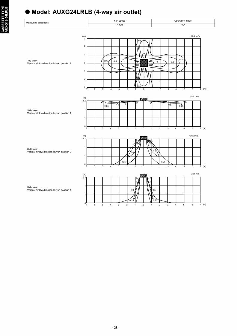
Model: AUXG24LRLB (4-way air outlet)
Measuring conditionsFan speed Operation mode
HIGH FAN
Top viewVertical airflow direction louver: position 1
Side viewVertical airflow direction louver: position 1
Side viewVertical airflow direction louver: position 2
Side viewVertical airflow direction louver: position 4
(m)
(m)
Unit: m/s3
2
1
0
3
2
1
1 1
1
1
1
1
2 2
2
2
2
2
03 34 4 556 67 7
0.5 0.5
0.5
0.5
0.250.25
(m)
(m)
Unit: m/s
3.2
2
1
01 12 203 34 4 556 67 7
0.25 0.5 1 20.5 0.25
12
(m)
(m)
Unit: m/s3.2
2
1
01 12 203 34 4 556 67 7
0.25
0.5
12
0.5
0.25
12
(m)
(m)
Unit: m/s
3.2
2
1
01 12 203 34 4 556 67 7
0.25
0.5
12
0.5
0.25
12

- 29 -
CA
SS
ET
TE
TY
PE
AU
XG
18-5
4LR
LB
Model: AUXG30LRLB (4-way air outlet)
Measuring conditionsFan speed Operation mode
HIGH FAN
Top viewVertical airflow direction louver: position 1
Side viewVertical airflow direction louver: position 1
Side viewVertical airflow direction louver: position 2
Side viewVertical airflow direction louver: position 4
(m)
(m)
Unit: m/s3
2
1
0
3
2
1
1 1
1
1
1
1
2 2
2
2
2
2
03 34 4 556 67 7
0.5 0.5
0.5
0.5
0.25 0.25
(m)
(m)
Unit: m/s
3.2
2
1
01 1
1 1
2 2
2 2
03 34 4 556 67 7
0.5 0.50.25 0.25
(m)
(m)
Unit: m/s
3.2
2
1
01 1
1 1
2 2
2 2
03 34 4 556 67 7
0.5 0.5
0.25 0.25
(m)
(m)
Unit: m/s
3.2
2
1
01 12 203 34 4 556 67 7
0.25
0.5
12
0.5
0.25
12
- 30 -
CA
SS
ET
TE
TY
PE
AU
XG
18-5
4LR
LB
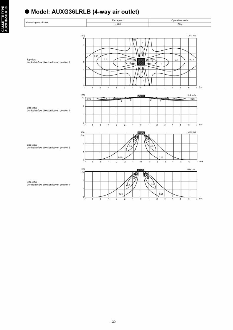
Model: AUXG36LRLB (4-way air outlet)
Measuring conditionsFan speed Operation mode
HIGH FAN
Top viewVertical airflow direction louver: position 1
Side viewVertical airflow direction louver: position 1
Side viewVertical airflow direction louver: position 2
Side viewVertical airflow direction louver: position 4
(m)
(m)
Unit: m/s3
2
1
0
3
2
1
1 1
1
2 2
2
03 34 4 556 67 7
0.5 0.25
1
2
0.5
12
0.50.25
2
10.5
(m)
(m)
Unit: m/s3.2
2
1
01 12 203 34 4 556 67 7
0.25 0.51 2
0.5 0.2512
(m)
(m)
Unit: m/s3.2
2
1
01 12 203 34 4 556 67 7
0.25
0.5
1
2
0.5
0.25
1
2
(m)
(m)
Unit: m/s3.2
2
1
01 12 203 34 4 556 67 7
0.25
0.5
1
2
0.5
0.25
1
2

- 31 -
CA
SS
ET
TE
TY
PE
AU
XG
18-5
4LR
LB
Model: AUXG45LRLB (4-way air outlet)
Measuring conditionsFan speed Operation mode
HIGH FAN
Top viewVertical airflow direction louver: position 1
Side viewVertical airflow direction louver: position 1
Side viewVertical airflow direction louver: position 2
Side viewVertical airflow direction louver: position 4
(m)
(m)
Unit: m/s3
2
1
0
3
2
1
1 1
1
2 2
2
03 34 4 556 67 7
0.5 0.25
1
2
0.5
1 20.50.25
2
10.5
(m)
(m)
Unit: m/s3.2
2
1
01 12 203 34 4 556 67 7
0.25 0.51 2
0.5 0.2512
(m)
(m)
Unit: m/s3.2
2
1
01 12 203 34 4 556 67 7
0.25
0.5
1
2
0.5
0.25
1
2
(m)
(m)
Unit: m/s
3.2
2
1
01 12 203 34 4 556 67 7
0.25
0.5
12
0.5
0.25
12

- 32 -
CA
SS
ET
TE
TY
PE
AU
XG
18-5
4LR
LB
Model: AUXG54LRLB (4-way air outlet)
Measuring conditionsFan speed Operation mode
HIGH FAN
Top viewVertical airflow direction louver: position 1
Side viewVertical airflow direction louver: position 1
Side viewVertical airflow direction louver: position 2
Side viewVertical airflow direction louver: position 4
(m)
(m)
Unit: m/s3
2
1
0
3
2
1
1 1
1
2 2
2
03 34 4 556 67 7
0.50.25
1
2
0.5
12
0.50.25
2
10.5
(m)
(m)
Unit: m/s3.2
2
1
01 12 203 34 4 556 67 7
0.25 0.51 2
0.5 0.2512
(m)
(m)
Unit: m/s
3.2
2
1
01 12 203 34 4 556 67 7
0.25
0.5
1
2
0.5
0.25
1
2
(m)
(m)
Unit: m/s3.2
2
1
01 12 203 34 4 556 67 7
0.25
0.5
1
2
0.5
0.25
1
2
- 33 -
CA
SS
ET
TE
TY
PE
AU
XG
18-5
4LR
LB
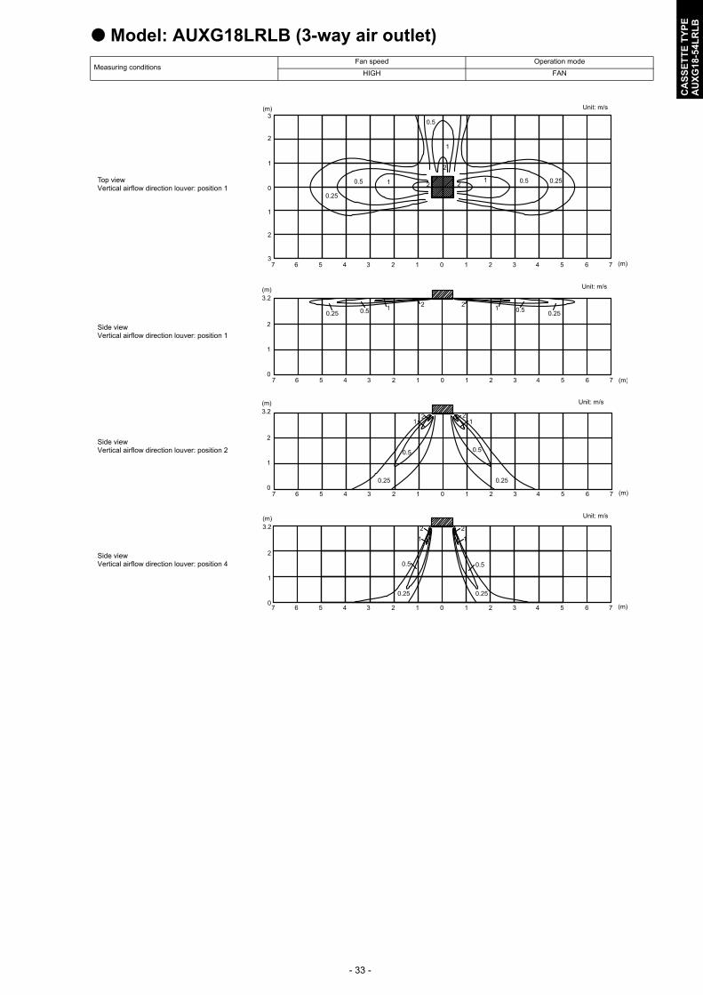
Model: AUXG18LRLB (3-way air outlet)
Measuring conditionsFan speed Operation mode
HIGH FAN
Top viewVertical airflow direction louver: position 1
Side viewVertical airflow direction louver: position 1
Side viewVertical airflow direction louver: position 2
Side viewVertical airflow direction louver: position 4
(m)
(m)
Unit: m/s3
2
1
0
3
2
1
1 1
1
2 2
2
03 34 4 556 67 7
0.5 0.25
1
2
0.5
1 20.5
0.25
(m)
(m)
Unit: m/s
3.2
2
1
01 12 203 34 4 556 67 7
0.25 0.5 1 20.5 0.25
12
(m)
(m)
Unit: m/s3.2
2
1
01 12 203 34 4 556 67 7
0.25
0.5
12
0.5
0.25
12
(m)
(m)
Unit: m/s
3.2
2
1
01 12 203 34 4 556 67 7
0.25
0.5
12
0.5
0.25
12
- 34 -
CA
SS
ET
TE
TY
PE
AU
XG
18-5
4LR
LB
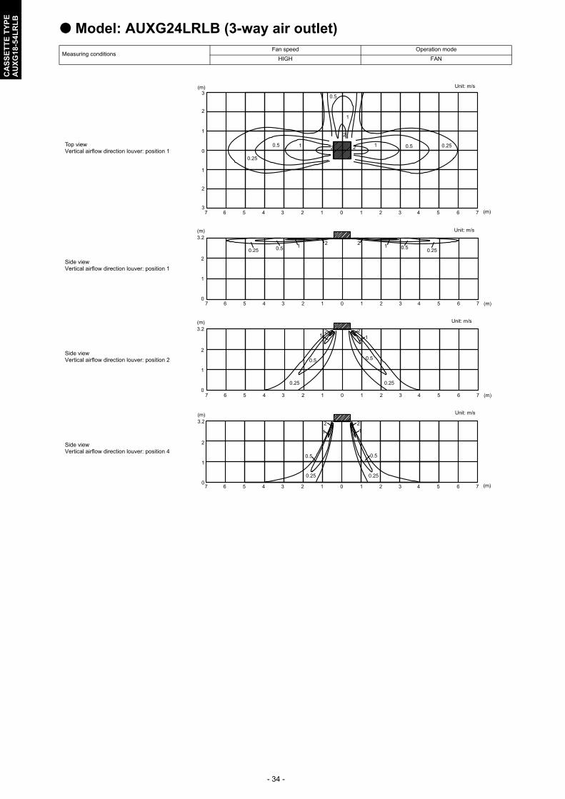
Model: AUXG24LRLB (3-way air outlet)
Measuring conditionsFan speed Operation mode
HIGH FAN
Top viewVertical airflow direction louver: position 1
Side viewVertical airflow direction louver: position 1
Side viewVertical airflow direction louver: position 2
Side viewVertical airflow direction louver: position 4
(m)
(m)
Unit: m/s3
2
1
0
3
2
1
1 1
1
2 2
2
03 34 4 556 67 7
0.5 0.25
1
2
0.5
1 20.5
0.25
(m)
(m)
Unit: m/s3.2
2
1
01 12 203 34 4 556 67 7
0.25 0.5 1 20.5 0.25
12
(m)
(m)
Unit: m/s3.2
2
1
01 12 203 34 4 556 67 7
0.25
0.5
12
0.5
0.25
12
(m)
(m)
Unit: m/s
3.2
2
1
01 12 203 34 4 556 67 7
0.25
0.5
12
0.5
0.25
12

- 35 -
CA
SS
ET
TE
TY
PE
AU
XG
18-5
4LR
LB
Model: AUXG30LRLB (3-way air outlet)
Measuring conditionsFan speed Operation mode
HIGH FAN
Top viewVertical airflow direction louver: position 1
Side viewVertical airflow direction louver: position 1
Side viewVertical airflow direction louver: position 2
Side viewVertical airflow direction louver: position 4
(m)
(m)
Unit: m/s3
2
1
0
3
2
1
1 1
1
2 2
2
03 34 4 556 67 7
0.50.25
1
2
0.5
12
0.5
0.25
(m)
(m)
Unit: m/s3.2
2
1
01 12 203 34 4 556 67 7
0.25 0.51 2
0.5 0.2512
(m)
(m)
Unit: m/s3.2
2
1
01 12 203 34 4 556 67 7
0.25
0.5
12
0.5
0.25
12
(m)
(m)
Unit: m/s3.2
2
1
01 12 203 34 4 556 67 7
0.25
0.51
2
0.5
0.25
1
2

- 36 -
CA
SS
ET
TE
TY
PE
AU
XG
18-5
4LR
LB
Model: AUXG36LRLB (3-way air outlet)
Measuring conditionsFan speed Operation mode
HIGH FAN
Top viewVertical airflow direction louver: position 1
Side viewVertical airflow direction louver: position 1
Side viewVertical airflow direction louver: position 2
Side viewVertical airflow direction louver: position 4
(m)
(m)
Unit: m/s3
2
1
0
3
2
1
1 1
1
2 2
2
03 34 4 556 67 7
0.5 0.25
1 20.5
0.25
2
10.5
(m)
(m)
Unit: m/s3.2
2
1
01 12 203 34 4 556 67 7
0.25 0.51 2
0.5 0.2512
(m)
(m)
Unit: m/s3.2
2
1
01 12 203 34 4 556 67 7
0.25
0.5
12
0.5
0.25
12
(m)
(m)
Unit: m/s3.2
2
1
0 1 12 203 34 4 556 67 70.25
0.5
1
2
0.5
0.25
1
2
- 37 -
CA
SS
ET
TE
TY
PE
AU
XG
18-5
4LR
LB
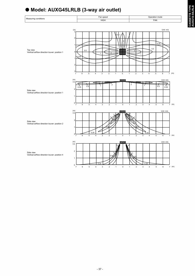
Model: AUXG45LRLB (3-way air outlet)
Measuring conditionsFan speed Operation mode
HIGH FAN
Top viewVertical airflow direction louver: position 1
Side viewVertical airflow direction louver: position 1
Side viewVertical airflow direction louver: position 2
Side viewVertical airflow direction louver: position 4
(m)
(m)
Unit: m/s3
2
1
0
3
2
1
1 1
1
2 2
2
03 34 4 556 67 7
0.5
0.25
1 20.5
0.25
2
10.5
(m)
(m)
Unit: m/s3.2
2
1
01 12 203 34 4 556 67 7
0.25 0.5 1 20.5 0.25
12
(m)
(m)
Unit: m/s3.2
2
1
01 12 203 34 4 556 67 7
0.25
0.5
12
0.5
0.25
1
2
(m)
(m)
Unit: m/s3.2
2
1
01 12 203 34 4 556 67 7
0.25
0.5
1
2
0.5
0.25
1
2
- 38 -
CA
SS
ET
TE
TY
PE
AU
XG
18-5
4LR
LB
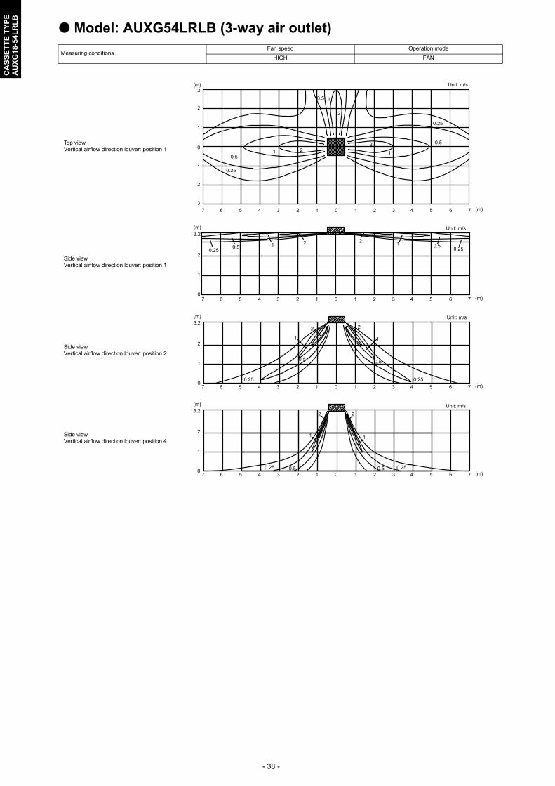
Model: AUXG54LRLB (3-way air outlet)
Measuring conditionsFan speed Operation mode
HIGH FAN
Top viewVertical airflow direction louver: position 1
Side viewVertical airflow direction louver: position 1
Side viewVertical airflow direction louver: position 2
Side viewVertical airflow direction louver: position 4
(m)
(m)
Unit: m/s3
2
1
0
3
2
1
1 1
1
2 2
2
03 34 4 556 67 7
0.5
0.25
1 20.5
0.25
2
10.5
(m)
(m)
Unit: m/s3.2
2
1
01 12 203 34 4 556 67 7
0.25 0.5 1 2 0.5 0.2512
(m)
(m)
Unit: m/s3.2
2
1
01 12 203 34 4 556 67 7
0.25
0.5
1
2
0.5
0.25
1
2
(m)
(m)
Unit: m/s3.2
2
1
01 12 203 34 4 556 67 7
0.25 0.5
1
2
0.5 0.25
1
2
- 39 -
CA
SS
ET
TE
TY
PE
AU
XG
18-5
4LR
LB
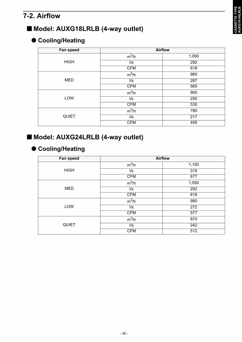
7-2. Airflow
Model: AUXG18LRLB (4-way outlet)
Cooling/Heating
Model: AUXG24LRLB (4-way outlet)
Cooling/Heating
Fan speed Airflow
HIGHm3/h 1,050
l/s 292
CFM 618
MEDm3/h 960
l/s 267
CFM 565
LOWm3/h 900
l/s 250
CFM 530
QUIETm3/h 780
l/s 217
CFM 459
Fan speed Airflow
HIGHm3/h 1,150
l/s 319
CFM 677
MEDm3/h 1,050
l/s 292
CFM 618
LOWm3/h 980
l/s 272
CFM 577
QUIETm3/h 870
l/s 242
CFM 512
- 40 -
CA
SS
ET
TE
TY
PE
AU
XG
18-5
4LR
LB
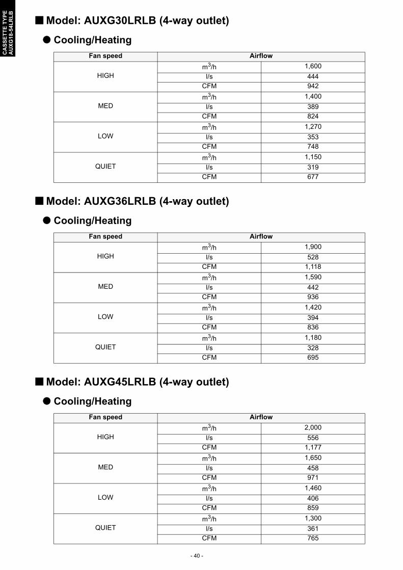
Model: AUXG30LRLB (4-way outlet)
Cooling/Heating
Model: AUXG36LRLB (4-way outlet)
Cooling/Heating
Model: AUXG45LRLB (4-way outlet)
Cooling/Heating
Fan speed Airflow
HIGHm3/h 1,600
l/s 444
CFM 942
MEDm3/h 1,400
l/s 389
CFM 824
LOWm3/h 1,270
l/s 353
CFM 748
QUIETm3/h 1,150
l/s 319
CFM 677
Fan speed Airflow
HIGHm3/h 1,900
l/s 528
CFM 1,118
MEDm3/h 1,590
l/s 442
CFM 936
LOWm3/h 1,420
l/s 394
CFM 836
QUIETm3/h 1,180
l/s 328
CFM 695
Fan speed Airflow
HIGHm3/h 2,000
l/s 556
CFM 1,177
MEDm3/h 1,650
l/s 458
CFM 971
LOWm3/h 1,460
l/s 406
CFM 859
QUIETm3/h 1,300
l/s 361
CFM 765

- 41 -
CA
SS
ET
TE
TY
PE
AU
XG
18-5
4LR
LB
Model: AUXG54LRLB (4-way outlet)
Cooling/Heating
Fan speed Airflow
HIGHm3/h 2,100
l/s 583
CFM 1,236
MEDm3/h 1,780
l/s 494
CFM 1,048
LOWm3/h 1,600
l/s 444
CFM 942
QUIETm3/h 1,320
l/s 367
CFM 777

- 42 -
CA
SS
ET
TE
TY
PE
AU
XG
18-5
4LR
LB
Model: AUXG18LRLB (3-way outlet)
Cooling/Heating
Model: AUXG24LRLB (3-way outlet)
Cooling/Heating
Fan speed Airflow
HIGHm3/h 915
l/s 254
CFM 539
MEDm3/h 835
l/s 232
CFM 491
LOWm3/h 785
l/s 218
CFM 462
QUIETm3/h 680
l/s 189
CFM 400
Fan speed Airflow
HIGHm3/h 1,000
l/s 278
CFM 589
MEDm3/h 915
l/s 254
CFM 538
LOWm3/h 850
l/s 236
CFM 500
QUIETm3/h 755
l/s 210
CFM 445

- 43 -
CA
SS
ET
TE
TY
PE
AU
XG
18-5
4LR
LB
Model: AUXG30LRLB (3-way outlet)
Cooling/Heating
Model: AUXG36LRLB (3-way outlet)
Cooling/Heating
Model: AUXG45LRLB (3-way outlet)
Cooling/Heating
Fan speed Airflow
HIGHm3/h 1,390
l/s 386
CFM 818
MEDm3/h 1,220
l/s 339
CFM 719
LOWm3/h 1,100
l/s 306
CFM 648
QUIETm3/h 1,000
l/s 278
CFM 589
Fan speed Airflow
HIGHm3/h 1,660
l/s 461
CFM 978
MEDm3/h 1,390
l/s 386
CFM 819
LOWm3/h 1,240
l/s 344
CFM 730
QUIETm3/h 1,030
l/s 286
CFM 607
Fan speed Airflow
HIGHm3/h 1,740
l/s 483
CFM 1,025
MEDm3/h 1,440
l/s 400
CFM 848
LOWm3/h 1,270
l/s 353
CFM 748
QUIETm3/h 1,130
l/s 314
CFM 666
- 44 -
CA
SS
ET
TE
TY
PE
AU
XG
18-5
4LR
LB
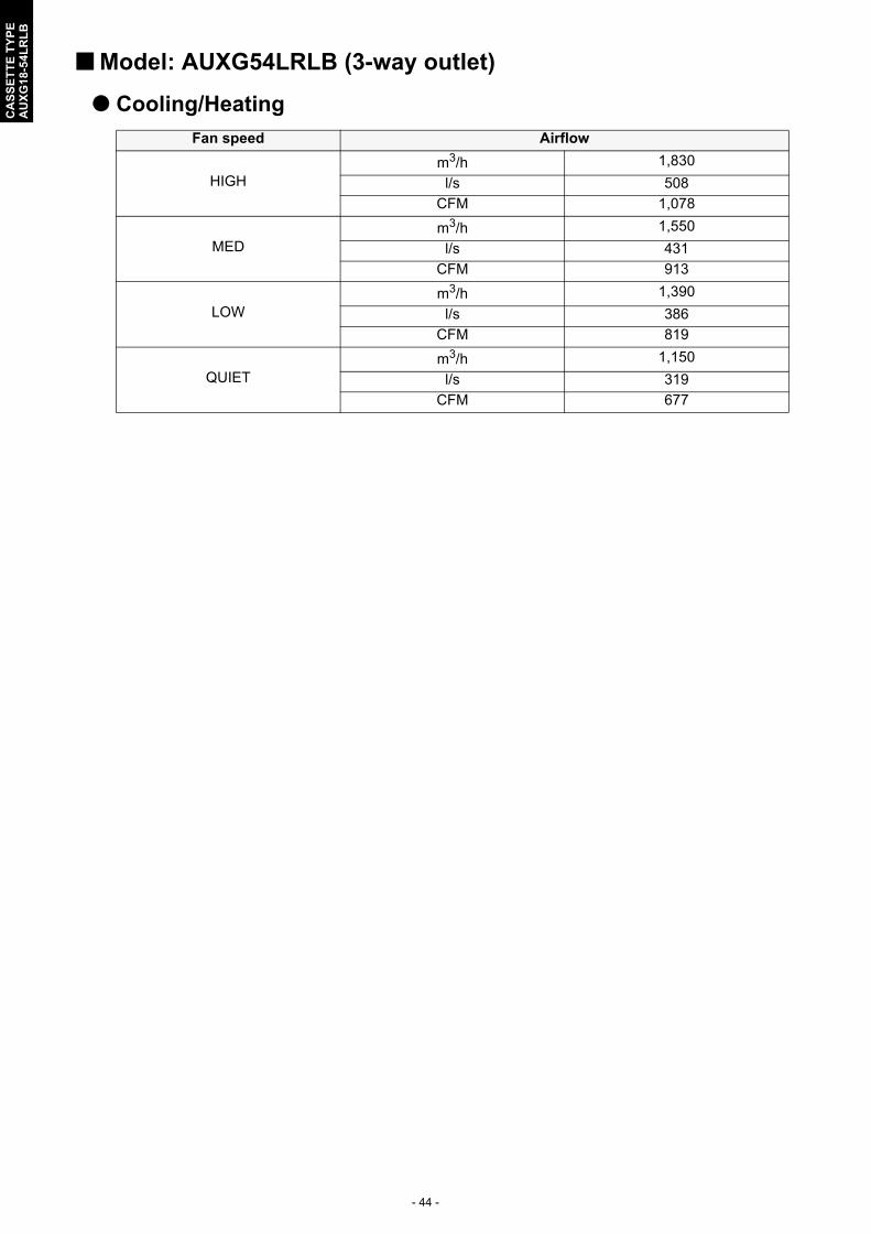
Model: AUXG54LRLB (3-way outlet)
Cooling/Heating
Fan speed Airflow
HIGHm3/h 1,830
l/s 508
CFM 1,078
MEDm3/h 1,550
l/s 431
CFM 913
LOWm3/h 1,390
l/s 386
CFM 819
QUIETm3/h 1,150
l/s 319
CFM 677
- 45 -
CA
SS
ET
TE
TY
PE
AU
XG
18-5
4LR
LB
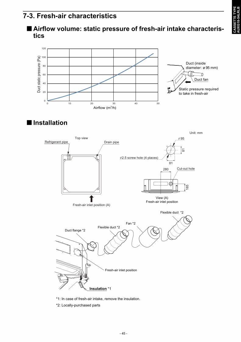
7-3. Fresh-air characteristics
Airflow volume: static pressure of fresh-air intake characteris-tics
Installation
Airflow (m3/h)
0
20
40
60
80
100
120
0 10 20 30 40 50
Duct
sta
tic p
ress
ure
(Pa)
Duct (inside diameter: ø 95 mm)
Static pressure required to take in fresh-air
Duct fan
280
185
2.5 screw hole (4 places)
95
81
81
Fresh-air inlet positionView (A)
Drain pipeRefrigerant pipeTop view
Fresh-air inlet position (A)
Cut-out hole
Unit: mm
Duct flange *2Flexible duct *2
Fan *2
Flexible duct *2
Insulation *1
*1: In case of fresh-air intake, remove the insulation.
*2: Locally-purchased parts
Fresh-air inlet position
- 46 -
CA
SS
ET
TE
TY
PE
AU
XG
18-5
4LR
LB
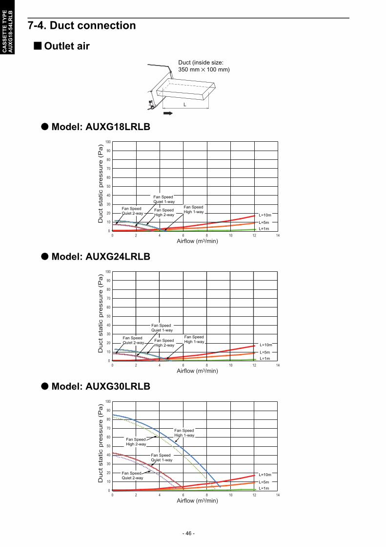
7-4. Duct connection
Outlet air
Model: AUXG18LRLB
Model: AUXG24LRLB
Model: AUXG30LRLB
L
Duct (inside size: 350 mm 100 mm)
0
10
20
30
40
50
60
70
80
90
100
0 2 4 6 8 10 12 14
Duct
sta
tic p
ress
ure
(P
a)
Airflow (m3/min)
L=10m
L=5mL=1m
Fan Speed Quiet 2-way
Fan Speed High 2-way
Fan Speed Quiet 1-way
Fan Speed High 1-way
0
10
20
30
40
50
60
70
80
90
100
0 2 4 6 8 10 12 14
Duct
sta
tic p
ress
ure
(P
a)
Airflow (m3/min)
L=10m
L=5mL=1m
Fan Speed Quiet 2-way
Fan Speed Quiet 1-way
Fan Speed High 2-way
Fan Speed High 1-way
L=10m
L=5mL=1m
Fan Speed Quiet 2-way
Fan Speed Quiet 1-way
Fan Speed High 1-way
Fan Speed High 2-way
0
10
20
30
40
50
60
70
80
90
100
0 2 4 6 8 10 12 14
Duct
sta
tic p
ress
ure
(P
a)
Airflow (m3/min)
- 47 -
CA
SS
ET
TE
TY
PE
AU
XG
18-5
4LR
LB
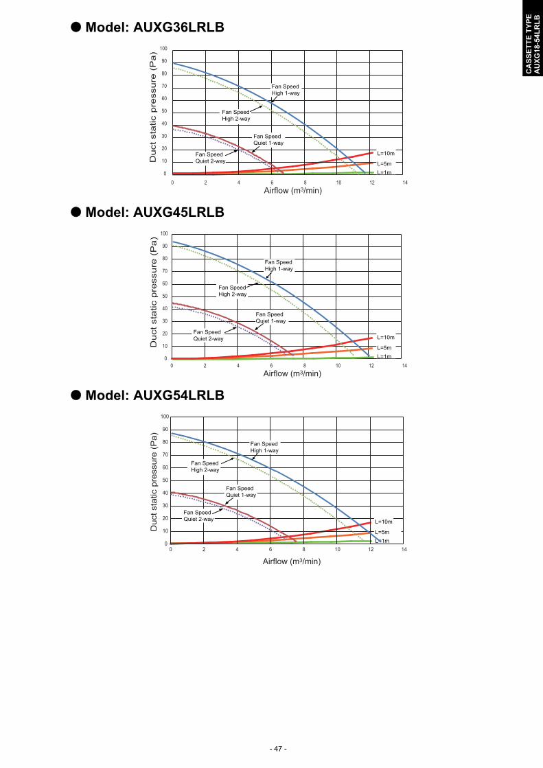
Model: AUXG36LRLB
Model: AUXG45LRLB
Model: AUXG54LRLB
0
10
20
30
40
50
60
70
80
90
100
0 2 4 6 8 10 12 14
Duct
sta
tic p
ress
ure
(P
a)
Airflow (m3/min)
Fan Speed Quiet 1-way
Fan Speed Quiet 2-way
Fan Speed High 2-way
Fan Speed High 1-way
L=10m
L=5mL=1m
0
10
20
30
40
50
60
70
80
90
100
0 2 4 6 8 10 12 14
Duct
sta
tic p
ress
ure
(P
a)
Airflow (m3/min)
Fan Speed High 1-way
Fan Speed High 2-way
Fan Speed Quiet 1-way
Fan Speed Quiet 2-way L=10m
L=5mL=1m
Airflow (m3/min)
0
10
20
30
40
50
60
70
80
90
100
0 2 4 6 8 10 12 14
Duc
t sta
tic p
ress
ure
(Pa)
Fan Speed High 2-way
Fan Speed Quiet 2-way
Fan Speed Quiet 1-way
Fan Speed High 1-way
L=10m
L=5mL=1m

- 48 -
CA
SS
ET
TE
TY
PE
AU
XG
18-5
4LR
LB
Precautions on air-outlet duct connection• Connect the air-outlet duct to maximum 2 directions among the 4-duct connecting directions.
! CAUTION
Do not connect ducts at 3 or more directions.
• When installing air-outlet duct in 2 directions, connect the ducts in a straight line.
• Once the ducted direction is decided, be sure to close the outlet in the direction.Use optional Air outlet shutter plate (UTR-YDZK) to close the outlet.
A
B
C
D
Air-outlet duct Air-outlet duct
CloseClose
Air-outlet duct
Air-outlet duct
Close
Close
Duct (locally purchased)
Close the outlet here.
- 49 -
CA
SS
ET
TE
TY
PE
AU
XG
18-5
4LR
LB
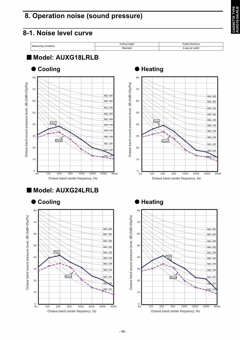
8. Operation noise (sound pressure)
8-1. Noise level curve
Model: AUXG18LRLB
Cooling Heating
Model: AUXG24LRLB
Cooling Heating
Measuring conditionsCeiling height Outlet directions
Standard 4-way air outlet
0
10
20
30
40
50
60
70
80
63 125 250 500 1000 2000 4000 8000
Oct
ave
band
sou
nd p
ress
ure
leve
l, dB
:(0dB
=20μ
Pa)
Octave band center frequency ,Hz
NC-65
NC-60
NC-55
NC-50
NC-45
NC-40
NC-35
NC-30
NC-25
NC-20
NC-15
High
Quiet
0
10
20
30
40
50
60
70
80
63 125 250 500 1000 2000 4000 8000
Oct
ave
band
sou
nd p
ress
ure
leve
l, dB
:(0dB
=20μ
Pa)
Octave band center frequency ,Hz
NC-65
NC-60
NC-55
NC-50
NC-45
NC-40
NC-35
NC-30
NC-25
NC-20
NC-15
High
Quiet
0
10
20
30
40
50
60
70
80
63 125 250 500 1000 2000 4000 8000
Oct
ave
band
sou
nd p
ress
ure
leve
l, dB
:(0dB
=20μ
Pa)
Octave band center frequency ,Hz
NC-65
NC-60
NC-55
NC-50
NC-45
NC-40
NC-35
NC-30
NC-25
NC-20
NC-15
High
Quiet
0
10
20
30
40
50
60
70
80
63 125 250 500 1000 2000 4000 8000
Oct
ave
band
sou
nd p
ress
ure
leve
l, dB
:(0dB
=20μ
Pa)
Octave band center frequency ,Hz
NC-65
NC-60
NC-55
NC-50
NC-45
NC-40
NC-35
NC-30
NC-25
NC-20
NC-15
High
Quiet
- 50 -
CA
SS
ET
TE
TY
PE
AU
XG
18-5
4LR
LB
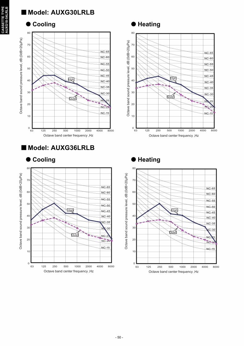
Model: AUXG30LRLB
Cooling Heating
Model: AUXG36LRLB
Cooling Heating
0
10
20
30
40
50
60
70
80
63 125 250 500 1000 2000 4000 8000
Oct
ave
band
sou
nd p
ress
ure
leve
l, dB
:(0dB
=20μ
Pa)
Octave band center frequency ,Hz
NC-65
NC-60
NC-55
NC-50
NC-45
NC-40
NC-35
NC-30
NC-25
NC-20
NC-15
High
Quiet
0
10
20
30
40
50
60
70
80
63 125 250 500 1000 2000 4000 8000O
ctav
e ba
nd s
ound
pre
ssur
e le
vel,
dB:(0
dB=2
0μP
a)
Octave band center frequency ,Hz
NC-65
NC-60
NC-55
NC-50
NC-45
NC-40
NC-35
NC-30
NC-25
NC-20
NC-15
High
Quiet
0
10
20
30
40
50
60
70
80
63 125 250 500 1000 2000 4000 8000
Oct
ave
band
sou
nd p
ress
ure
leve
l, dB
:(0dB
=20μ
Pa)
Octave band center frequency ,Hz
NC-65
NC-60
NC-55
NC-50
NC-45
NC-40
NC-35
NC-30
NC-25
NC-20
NC-15
High
Quiet
0
10
20
30
40
50
60
70
80
63 125 250 500 1000 2000 4000 8000
Oct
ave
band
sou
nd p
ress
ure
leve
l, dB
:(0dB
=20μ
Pa)
Octave band center frequency ,Hz
NC-65
NC-60
NC-55
NC-50
NC-45
NC-40
NC-35
NC-30
NC-25
NC-20
NC-15
-
High
Quiet

- 51 -
CA
SS
ET
TE
TY
PE
AU
XG
18-5
4LR
LB
Model: AUXG45LRLB
Cooling Heating
Model: AUXG54LRLB
Cooling Heating
0
10
20
30
40
50
60
70
80
63 125 250 500 1000 2000 4000 8000
Oct
ave
band
sou
nd p
ress
ure
leve
l, dB
:(0dB
=20μ
Pa)
Octave band center frequency ,Hz
NC-65
NC-60
NC-55
NC-50
NC-45
NC-40
NC-35
NC-30
NC-25
NC-20
NC-15
-
High
Quiet
0
10
20
30
40
50
60
70
80
63 125 250 500 1000 2000 4000 8000O
ctav
e ba
nd s
ound
pre
ssur
e le
vel,
dB:(0
dB=2
0μP
a)Octave band center frequency ,Hz
NC-65
NC-60
NC-55
NC-50
NC-45
NC-40
NC-35
NC-30
NC-25
NC-20
NC-15
High
Quiet
0
10
20
30
40
50
60
70
80
63 125 250 500 1000 2000 4000 8000
Oct
ave
band
sou
nd p
ress
ure
leve
l, dB
:(0dB
=20μ
Pa)
Octave band center frequency ,Hz
NC-65
NC-60
NC-55
NC-50
NC-45
NC-40
NC-35
NC-30
NC-25
NC-20
NC-15
High
Quiet
0
10
20
30
40
50
60
70
80
63 125 250 500 1000 2000 4000 8000
Oct
ave
band
sou
nd p
ress
ure
leve
l, dB
:(0dB
=20μ
Pa)
Octave band center frequency ,Hz
NC-65
NC-60
NC-55
NC-50
NC-45
NC-40
NC-35
NC-30
NC-25
NC-20
NC-15
High
Quiet
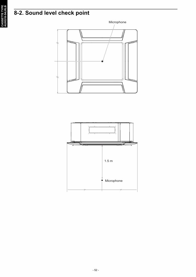
- 52 -
CA
SS
ET
TE
TY
PE
AU
XG
18-5
4LR
LB
8-2. Sound level check point
Microphone
Microphone
1.5 m

- 53 -
CA
SS
ET
TE
TY
PE
AU
XG
18-5
4LR
LB
9. Safety devices
*: Printed Circuit Board
Type of protection Protection formModel
AUXG18LRLB AUXG24LRLB
Circuit protectionCurrent fuse(PCB*)
250 V, 3.15 A
Fan motor protection
Thermal protection program
Activate125 ± 10 °C
Fan motor stop
Reset120 ± 10 °C
Fan motor restart
Type of protection
Protection formModel
AUXG30LRLB AUXG36LRLB AUXG45LRLB AUXG54LRLB
Circuit protection
Current fuse(PCB*)
250 V, 3.15 A
Fan motor protection
Thermal protection program
Activate125 ± 10 °C
Fan motor stop
Reset120 ± 10 °C
Fan motor restart

- 54 -
CA
SS
ET
TE
TY
PE
AU
XG
18-5
4LR
LB
10. External input and output
10-1. External input• “Operation/Stop” mode or "Forced stop" mode can be selected with function setting of indoor unit.• A twisted pair cable (22AWG) should be used. Maximum length of cable is 150 m.• The wire connection should be separate from the power cable line.
Indoor unitIndoor unit functions such as Operation/Stop can be done by using indoor unit terminals.
*1: The switch can be used on the following condition: DC 12 V to 24 V, 1 mA to 15 mA.
PCB External input External output Connector Input selectInput signal
External connect kit
(Optional parts)
Indoor unit
Operation/Stop - Terminal Dry contact Edge -
-
Operation status
CN47 - - UTY-XWZXZG
Error status
Indoor unit fan operation status
External heater output
External input and
output(UTY-XCSX)
Operation/Stop-
Input 1/Input 2 Dry contact/
Apply voltage
Edge/Pulse
-Forced thermostat off
Input 1 Edge
-
Operation status
Output 1Output 2Output 3
- - -
Error status
Indoor unit status
External heater output
Terminal(Ext.in)
CN65(Ext.in/out PCB)
CN47(Ext.out)
Rotary switch
SW2
SW1
Fig. External input and output PCBFig. Indoor unit PCB
1
2Terminal
PCB

- 55 -
CA
SS
ET
TE
TY
PE
AU
XG
18-5
4LR
LB
External input and output PCBThe indoor unit Operation/Stop can be set by using the input terminal on the PCB.
Input selectUse either one of these types of terminals according to the application. (Both types of terminalscannot be used simultaneously.)• Dry contactIn case of internal power supply, set the slide switch of SW1 to "NON VOL" side.
*1: The switches can be used on the following condition: DC 12 V to 24 V, 1 mA to 15 mA.
• Apply voltageIn case of external power supply, set the slide switch of SW1 to "VOL" side.
*1: The switches can be used on the following condition: DC 12 V to 24 V, 1 mA to 15 mA.*2: Make the power supply DC 12 V to 24 V 10 mA or more.
1
2
CInput 1 Input 2
PCB
Connected unit
+
+
-
1
2
CInput 1 Input 2 Power supply
PCB
Connected unit
+-
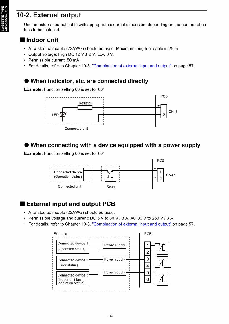
- 56 -
CA
SS
ET
TE
TY
PE
AU
XG
18-5
4LR
LB
10-2. External outputUse an external output cable with appropriate external dimension, depending on the number of ca-bles to be installed.
Indoor unit• A twisted pair cable (22AWG) should be used. Maximum length of cable is 25 m.• Output voltage: High DC 12 V ± 2 V, Low 0 V.• Permissible current: 50 mA• For details, refer to Chapter 10-3. "Combination of external input and output" on page 57.
When indicator, etc. are connected directlyExample: Function setting 60 is set to "00"
When connecting with a device equipped with a power supplyExample: Function setting 60 is set to "00"
External input and output PCB• A twisted pair cable (22AWG) should be used.• Permissible voltage and current: DC 5 V to 30 V / 3 A, AC 30 V to 250 V / 3 A• For details, refer to Chapter 10-3. "Combination of external input and output" on page 57.
1
2CN47
LED
PCB
Resistor
Connected unit
+
-
1
2Connected device
CN47
PCB
Connected unit Relay
(Operation status) -
+
1
2
3
45
6
Power supply
Power supply
Power supply
PCB
Connected device 1(Operation status)
Connected device 2(Error status)
(Indoor unit fanoperation status)
Connected device 3
Example
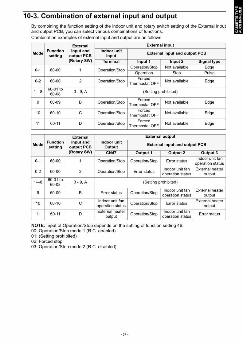
- 57 -
CA
SS
ET
TE
TY
PE
AU
XG
18-5
4LR
LB
10-3. Combination of external input and outputBy combining the function setting of the indoor unit and rotary switch setting of the External inputand output PCB, you can select various combinations of functions.Combination examples of external input and output are as follows:
NOTE: Input of Operation/Stop depends on the setting of function setting 46.00: Operation/Stop mode 1 (R.C. enabled)01: (Setting prohibited)02: Forced stop03: Operation/Stop mode 2 (R.C. disabled)
ModeFunction setting
External input and
output PCB (Rotary SW)
External input
Indoor unit Input
External input and output PCB
Terminal Input 1 Input 2 Signal type
0-1 60-00 1 Operation/StopOperation/Stop Not available Edge
Operation Stop Pulse
0-2 60-00 2 Operation/StopForced
Thermostat OFFNot available Edge
1—860-01 to 60-08
3 - 9, A (Setting prohibited)
9 60-09 B Operation/StopForced
Thermostat OFFNot available Edge
10 60-10 C Operation/StopForced
Thermostat OFFNot available Edge
11 60-11 D Operation/StopForced
Thermostat OFFNot available Edge
ModeFunction setting
External input and
output PCB (Rotary SW)
External output
Indoor unit Output
External input and output PCB
CN47 Output 1 Output 2 Output 3
0-1 60-00 1 Operation/Stop Operation/Stop Error statusIndoor unit fan
operation status
0-2 60-00 2 Operation/Stop Error statusIndoor unit fan
operation statusExternal heater
output
1—860-01 to 60-08
3 - 9, A (Setting prohibited)
9 60-09 B Error status Operation/StopIndoor unit fan
operation statusExternal heater
output
10 60-10 CIndoor unit fan
operation statusOperation/Stop Error status
External heater output
11 60-11 DExternal heater
outputOperation/Stop
Indoor unit fan operation status
Error status
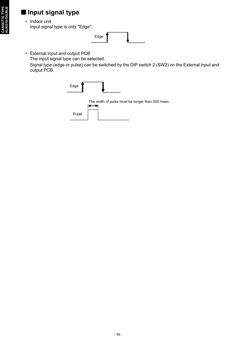
- 58 -
CA
SS
ET
TE
TY
PE
AU
XG
18-5
4LR
LB
Input signal type• Indoor unit
Input signal type is only "Edge".
• External input and output PCBThe input signal type can be selected.Signal type (edge or pulse) can be switched by the DIP switch 2 (SW2) on the External input andoutput PCB.
Edge
Edge
Pulse
The width of pulse must be longer than 200 msec.

- 59 -
CA
SS
ET
TE
TY
PE
AU
XG
18-5
4LR
LB
10-4. Details of function
Control input function
When function setting is "Operation/Stop" mode 1• In the case of "Edge" input
• In the case of "Pulse" input
NOTES: • The last command has priority.• The indoor units within the same remote controller group operates in the same mode.
Function setting /
Rotary SW of External input and
output PCBExternal input Input signal Command
46-00
- Input of indoor unit TerminalOff → On Operation
On → Off Stop
60-00 / 1External input and
output PCBInput 1
Off → On Operation
On → Off Stop
Function setting /
Rotary SW of External input and
output PCBExternal input Input signal Command
46-00 60-00 / 1External input and
output PCBInput 1 Pulse Operation
Input 2 Pulse Stop
OperationStop
Remote controller
OnOff
Indoor unit
On
Input
On
On
Off
Operation
Stop
Remote controller
On
Off
Indoor unit
Input 1
Input 2

- 60 -
CA
SS
ET
TE
TY
PE
AU
XG
18-5
4LR
LB
When function setting is "Forced stop" mode• In the case of "Edge" input
• In the case of "Pulse" input
NOTES: • When the forced stop is triggered, indoor unit stops and Operation/Stop operation by the
remote controller is restricted.• When forced stop function is used with forming a remote controller group, connect the same
equipment to each indoor unit within the group.
Function setting /
Rotary SW of External input and
output PCBExternal input Input signal Command
46-02
- Input of indoor unit TerminalOff → On Forced stop
On → Off Normal
60-00 / 1External input and
output PCBInput 1
Off → On Forced stop
On → Off Normal
Function setting /
Rotary SW of External input and
output PCBExternal input Input signal Command
46-02 60-00 / 1External input and
output PCBInput 1 Pulse Forced stop
Input 2 Pulse Normal
On
Off
Forced stopNormal
OperationStop
Remote controller On On
Indoor unit
On
Input
On
Off
Operation
Stop
Remote controller
On
Off
Forced stop
Normal
Input 1
Input 2
On On On
Indoor unit

- 61 -
CA
SS
ET
TE
TY
PE
AU
XG
18-5
4LR
LB
When function setting is "Operation/Stop" mode 2• In the case of "Edge" input
• In the case of "Pulse" input
NOTES: • When "Operation/Stop" mode 2 function is used with forming a remote controller group,
connect the same equipment to each indoor unit within the group.
Function setting /
Rotary SW of External input and
output PCBExternal input Input signal Command
46-03
- Input of indoor unit TerminalOff → On Operation
On → OffStop (R.C. disabled)
60-00 / 1External input and
output PCBInput 1
Off → On Operation
On → OffStop (R.C. disabled)
Function setting /
Rotary SW of External input and
output PCBExternal input Input signal Command
46-03 60-00 / 1External input and
output PCB
Input 1 Pulse Operation
Input 2 PulseStop (R.C. disabled)
OnInput
Off
OperationIndoor unit
Stop(R.C. disabled)
Remote controller On OnOff
On
On
Off
Operation
Stop
Remote controller
On
Off
Indoor unit
Input 1
Input 2
(R.C. disabled)
Off On

- 62 -
CA
SS
ET
TE
TY
PE
AU
XG
18-5
4LR
LB
Forced thermostat off function
Control output function
The output is low when the unit is stopped.
Function setting /
Rotary SW of External input and output PCB
External input Input signal Command
60-00 / 2
External input and output PCB
Input 1
Off →OnThermostat
off60-09 / B
60-10 / COn → Off
Normal operation60-11 / D
Function setting /
Rotary SW of External input and output PCB
External outputOutput signal
Command
60-00 / 1, 2 Output of indoor unit CN47Low → High Operation
High → Low Stop
60-00 / 1
External input and output PCB
Output 1
Off → On Operation60-09 / B
60-10 / COn → Off Stop
60-11 / D
OnOff
OnOff
Compressor
Room temp.
Set temp.
Input
Operation
Stop
High
LowCN47
On
OffOutput 1
Indoor unit

- 63 -
CA
SS
ET
TE
TY
PE
AU
XG
18-5
4LR
LB
Error status
The output is ON when an error is generated for the indoor unit.
Indoor unit fan operation status
Function setting /
Rotary SW of External input and output PCB
External outputOutput signal
Command
60-09 / B Output of indoor unit CN47Low → High Error
High → Low Normal
60-00 / 2
External input and output PCB
Output 1Off → On Error
On → Off Normal
60-00 / 1Output 2
Off → On Error
60-10 / C On → Off Normal
60-11 / D Output 3Off → On Error
On → Off Normal
Function setting /
Rotary SW of External input and output PCB
External outputOutput signal
Command
60-10 / C Output of indoor unit CN47Low → High Fan run
High → Low Fan stop
60-00 / 2
External input and output PCB
Output 2
Off → On Fan run
60-09 / BOn → Off Fan stop
60-11 / D
60-00 / 1 Output 3Off → On Fan run
On → Off Fan stop
Output signal Condition
OnThe indoor unit fan is operating.
Low → High
Off The fan is stopped or during cold air prevention.
High → Low During thermostat off when in dry mode operation.
Error
Normal
High
LowCN47
On
OffOutput 1, 2, 3
Indoor unit
Fan run
Fan stop
High
LowCN47
On
OffOutput 2, 3
Indoor unit

- 64 -
CA
SS
ET
TE
TY
PE
AU
XG
18-5
4LR
LB
External heater output
Specifications of the signal output performance are as shown as follows:
Example: When set temperature (Ts) is set at 22 °C;• And room temperature (Tr) increase above 12 °C, signal output is on.• And Tr increase above 21 °C, signal output is off.• And Tr decrease below 19 °C, signal output is on.• And Tr decrease below 10 °C, signal output is off.
The output also turns off in defrost operation.
Function setting /
Rotary SW of External input and output PCB
External outputOutput signal
Command
60-11 / D Output of indoor unit CN47Low → High Heater on
High → Low Heater off
60-00 / 2External input and output
PCBOutput 3
Off → On Heater on60-09 / B
60-10 / C On → Off Heater off
Output signal Condition
Low → HighHeater turns on as shown in diagram of heating temperature
Off → On
High → Low
Heater turns off as shown in diagram of heating temperature
• Other than Heating modeOn → Off • Error occurred
• Forced thermo off• Fan stop protection
Off
Off
On
Tr-Ts
Tr-Ts=-1 °C
Tr-Ts=-10 °C
Tr-Ts=-3 °C
Tr-Ts=-12 °C
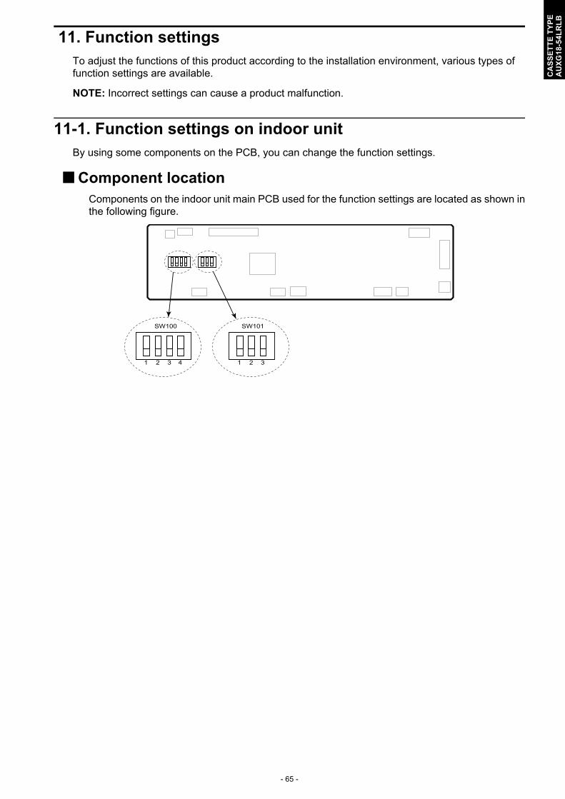
- 65 -
CA
SS
ET
TE
TY
PE
AU
XG
18-5
4LR
LB
11. Function settingsTo adjust the functions of this product according to the installation environment, various types of function settings are available.
NOTE: Incorrect settings can cause a product malfunction.
11-1. Function settings on indoor unitBy using some components on the PCB, you can change the function settings.
Component locationComponents on the indoor unit main PCB used for the function settings are located as shown inthe following figure.
SW100
1 2 3 4
SW101
1 2 3
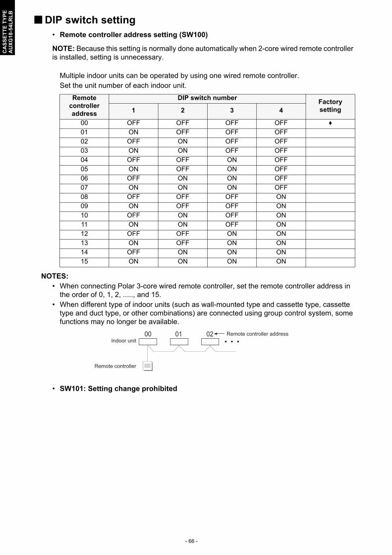
- 66 -
CA
SS
ET
TE
TY
PE
AU
XG
18-5
4LR
LB
DIP switch setting• Remote controller address setting (SW100)
NOTE: Because this setting is normally done automatically when 2-core wired remote controller is installed, setting is unnecessary.
Multiple indoor units can be operated by using one wired remote controller.Set the unit number of each indoor unit.
NOTES: • When connecting Polar 3-core wired remote controller, set the remote controller address in
the order of 0, 1, 2, ....., and 15.• When different type of indoor units (such as wall-mounted type and cassette type, cassette
type and duct type, or other combinations) are connected using group control system, some functions may no longer be available.
• SW101: Setting change prohibited
Remote controller address
DIP switch numberFactory setting1 2 3 4
00 OFF OFF OFF OFF ♦
01 ON OFF OFF OFF
02 OFF ON OFF OFF
03 ON ON OFF OFF
04 OFF OFF ON OFF
05 ON OFF ON OFF
06 OFF ON ON OFF
07 ON ON ON OFF
08 OFF OFF OFF ON
09 ON OFF OFF ON
10 OFF ON OFF ON
11 ON ON OFF ON
12 OFF OFF ON ON
13 ON OFF ON ON
14 OFF ON ON ON
15 ON ON ON ON
00 01 02 Remote controller addressIndoor unit
Remote controller

- 67 -
CA
SS
ET
TE
TY
PE
AU
XG
18-5
4LR
LB
11-2. Function settings by using remote controllerSome function settings can be changed on the remote controller. After confirming the setting proce-dure and the content of each function setting, select appropriate functions for your installation envi-ronment.
NOTE: Incorrect settings can cause a product malfunction.
Setting procedure by using wired remote controllerThe function number and the associated setting value are displayed on the LCD of the remote controller. Follow the instructions written in the local setup procedure supplied with the remote controller, and select appropriate setting according to the installation environment.
Before turning on the power of the indoor unit, reconfirm following items:• Piping air tight test and vacuuming have been performed firmly.• There is no wiring mistake.
1. Turn on the power.
2. Touch the “Function Setting” on the “Maintenance” screen. The “Function Setting” screen is displayed. Then touch the “Address” on the “Function Setting” screen.
3. “Address” screen is displayed. Select the address of the indoor unit whose function number is to be set by touching ▲ or ▼. When setting at all the indoor units, touch “All”.
NOTE: Perform this step only when the remote controller address setting is required. Otherwise, skip this step.
4. Touch the “Function No.” on the “Function Setting” screen.
5. “Function No.” screen is displayed. Set the function number “11” by touching ▲ or ▼. When the “OK” is touched, the display returns to the “Function Setting” screen.
[002–01]
[00]
[00]
Address
Function No.
Setting No.
Function Setting
Back Setting
002–01
Address
Cancel OK
All
[002–01]
[00]
[00]
Address
Function No.
Setting No.
Function Setting
Back Setting
11
Function No.
Cancel OK
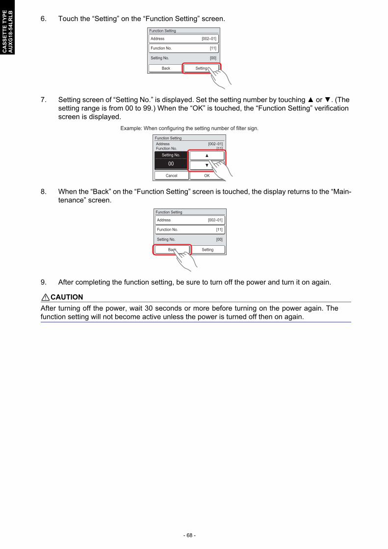
- 68 -
CA
SS
ET
TE
TY
PE
AU
XG
18-5
4LR
LB
6. Touch the “Setting” on the “Function Setting” screen.
7. Setting screen of “Setting No.” is displayed. Set the setting number by touching ▲ or ▼. (The setting range is from 00 to 99.) When the “OK” is touched, the “Function Setting” verification screen is displayed.
8. When the “Back” on the “Function Setting” screen is touched, the display returns to the “Main-tenance” screen.
9. After completing the function setting, be sure to turn off the power and turn it on again.
! CAUTION
After turning off the power, wait 30 seconds or more before turning on the power again. Thefunction setting will not become active unless the power is turned off then on again.
[002–01]
[11]
[00]
Address
Function No.
Setting No.
Function Setting
Back Setting
00
[002–01][11]
Function Setting
Cancel OK
AddressFunction No.
Setting No.
Example: When configuring the setting number of filter sign.
[002–01]
[11]
[00]
Address
Function No.
Setting No.
Function Setting
Back Setting

- 69 -
CA
SS
ET
TE
TY
PE
AU
XG
18-5
4LR
LB
Contents of function settingEach function setting listed in this section is adjustable in accordance with the installation environ-ment.
NOTE: Setting will not be changed if invalid numbers or setting values are selected.
1) Filter sign
Select appropriate intervals for displaying the filter sign on the indoor unit according to the estimatedamount of dust in the air of the room.If the indication is not required, select "No indication" (03).
Intervals will differ depending on the indoor unit type as follows.
2) Ceiling height
Select the appropriate ceiling height according to the place of installation.
For the specific height for each setting value, refer to Chapter 4. "Installation space requirement" onpage 19.
In case of cassette type models: The ceiling height values are for the 4-way outlet. Do not change this setting in the 3-way outlet mode.
3) Outlet directions
Select the appropriate number of outlet directions according to the installation conditions.
Function no. Functions
1) 11 Filter sign
2) 20 Ceiling height
3) 22 Outlet directions
4) 23 Vertical airflow direction range control
5) 30/31 Room temperature control for indoor unit sensor
6) 35/36 Room temperature control for wired remote controller sensor
7) 40 Auto restart
8) 42 Room temperature sensor switching
9) 44 Remote controller custom code
10) 46 External input control
11) 48 Room temperature sensor switching (Aux.)
12) 49 Indoor unit fan control for energy saving for cooling
13) 60 Switching functions for external output terminal
Function number Setting value Setting description Factory setting
11
00 Standard (2,500 hours)
01 Long interval (4,400 hours)
02 Short interval (1,250 hours)
03 No indication ♦
Function number Setting value Setting description Factory setting
20
00 Standard ♦
01 High ceiling
02 Low ceiling
Function number Setting value Setting description Factory setting
2200 4-way ♦
01 3-way
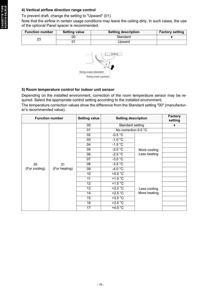
- 70 -
CA
SS
ET
TE
TY
PE
AU
XG
18-5
4LR
LB
4) Vertical airflow direction range control
To prevent draft, change the setting to "Upward" (01).Note that the airflow in certain usage conditions may leave the ceiling dirty. In such cases, the useof the optional Panel spacer is recommended.
5) Room temperature control for indoor unit sensor
Depending on the installed environment, correction of the room temperature sensor may be re-quired. Select the appropriate control setting according to the installed environment.The temperature correction values show the difference from the Standard setting "00" (manufactur-er’s recommended value).
Function number Setting value Setting description Factory setting
2300 Standard ♦
01 Upward
Function number Setting value Setting descriptionFactory setting
30(For cooling)
31(For heating)
00 Standard setting ♦
01 No correction 0.0 °C
02 -0.5 °C
More coolingLess heating
03 -1.0 °C
04 -1.5 °C
05 -2.0 °C
06 -2.5 °C
07 -3.0 °C
08 -3.5 °C
09 -4.0 °C
10 +0.5 °C
Less coolingMore heating
11 +1.0 °C
12 +1.5 °C
13 +2.0 °C
14 +2.5 °C
15 +3.0 °C
16 +3.5 °C
17 +4.0 °C
Ceiling
Swing scope (standard)
Swing scope (upward)

- 71 -
CA
SS
ET
TE
TY
PE
AU
XG
18-5
4LR
LB
6) Room temperature control for wired remote controller sensor
Depending on the installed environment, correction of the wire remote temperature sensor may berequired. Select the appropriate control setting according to the installed environment.To change this setting, set Function 42 to Both “01”.Ensure that the Thermo Sensor icon is displayed on the remote controller screen.
7) Auto restart
Enables or disables automatic restart after a power interruption.
NOTE: Auto restart is an emergency function such as for power outage etc. Do not attempt to use this function in normal operation. Be sure to operate the unit by remote controller or external device.
8) Room temperature sensor switching
(Only for wired remote controller)When using the wired remote controller temperature sensor, change the setting to "Both" (01).
00: Sensor on the indoor unit is active.01: Sensors on both indoor unit and wired remote controller are active.
NOTE: Remote controller sensor must be turned on by using the remote controller.
Function number Setting value Setting descriptionFactory setting
35(For cooling)
36(For heating)
00 No correction ♦
01 No correction 0.0°C
02 -0.5 °C
More coolingLess heating
03 -1.0 °C
04 -1.5 °C
05 -2.0 °C
06 -2.5 °C
07 -3.0 °C
08 -3.5 °C
09 -4.0 °C
10 +0.5 °C
Less coolingMore heating
11 +1.0 °C
12 +1.5 °C
13 +2.0 °C
14 +2.5 °C
15 +3.0 °C
16 +3.5 °C
17 +4.0 °C
Function number Setting value Setting description Factory setting
4000 Enable ♦
01 Disable
Function number Setting value Setting description Factory setting
4200 Indoor unit ♦
01 Both

- 72 -
CA
SS
ET
TE
TY
PE
AU
XG
18-5
4LR
LB
9) Remote controller custom code
(Only for wireless remote controller)The indoor unit custom code can be changed. Select the appropriate custom code.
10) External input control
"Operation/Stop" mode or "Forced stop" mode can be selected.
11) Room temperature sensor switching (Aux.)
To use the temperature sensor on the wired remote controller only, change the setting to "Wiredremote controller" (01).This function will only work if the function setting 42 is set at "Both" (01).
12) Indoor unit fan control for energy saving for cooling
Enables or disables the power-saving function by controlling the indoor unit fan rotation when theoutdoor unit is stopped during cooling operation.
00: When the outdoor unit is stopped, the indoor unit fan operates continuously following the setting on the remote controller.
01: When the outdoor unit is stopped, the indoor unit fan operates intermittently at a very low speed.
02: Enable or disable this function by remote controller setting.
NOTES: • As the factory setting, this setting is initially activated.• Set to "00" or "01" when connecting a remote controller that cannot set the Fan control for energy
saving function or connecting a network converter.To confirm if the remote controller has this setting, refer to the operating manual of each remotecontroller.
Function number Setting value Setting description Factory setting
44
00 A ♦
01 B
02 C
03 D
Function number Setting value Setting description Factory setting
46
00 Operation/Stop mode 1 ♦
01 (Setting prohibited)
02 Forced stop mode
03 Operation/Stop mode 2
Function number Setting value Setting description Factory setting
4800 Both ♦
01 Wired remote controller
Function number Setting value Setting description Factory setting
49
00 Disable
01 Enable
02 Remote controller ♦

- 73 -
CA
SS
ET
TE
TY
PE
AU
XG
18-5
4LR
LB
13) Switching functions for external output terminal
Functions of the external output terminal can be switched. For details, refer to “External input andoutput”.
Function number Setting value Setting description Factory setting
60
00 Operation status ♦
01 - 08 (Setting prohibited)
09 Error status
10 Indoor unit fan operation status
11 External heater
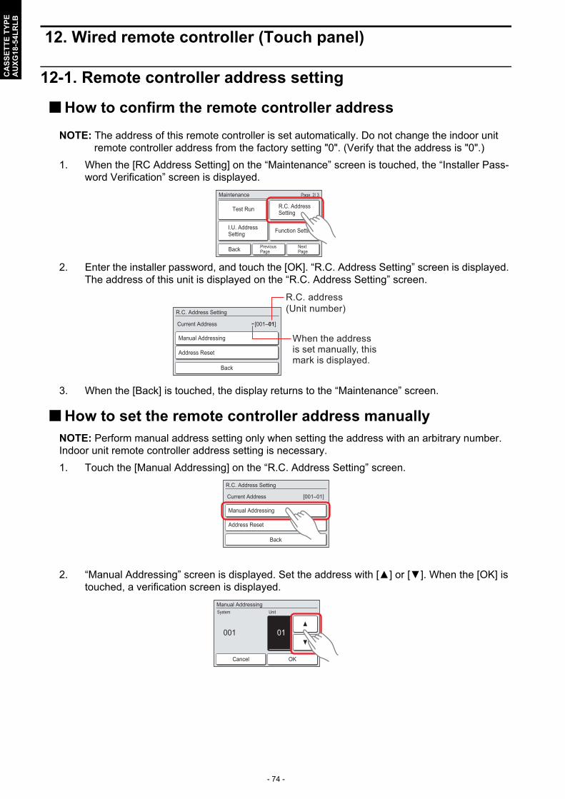
- 74 -
CA
SS
ET
TE
TY
PE
AU
XG
18-5
4LR
LB
12. Wired remote controller (Touch panel)
12-1. Remote controller address setting
How to confirm the remote controller address
NOTE: The address of this remote controller is set automatically. Do not change the indoor unit remote controller address from the factory setting "0". (Verify that the address is "0".)
1. When the [RC Address Setting] on the “Maintenance” screen is touched, the “Installer Pass-word Verification” screen is displayed.
2. Enter the installer password, and touch the [OK]. “R.C. Address Setting” screen is displayed. The address of this unit is displayed on the “R.C. Address Setting” screen.
3. When the [Back] is touched, the display returns to the “Maintenance” screen.
How to set the remote controller address manuallyNOTE: Perform manual address setting only when setting the address with an arbitrary number. Indoor unit remote controller address setting is necessary.
1. Touch the [Manual Addressing] on the “R.C. Address Setting” screen.
2. “Manual Addressing” screen is displayed. Set the address with [▲] or [▼]. When the [OK] is touched, a verification screen is displayed.
PreviousPageBack Next
Page
Page 2/ 3Maintenance
Test Run R.C. AddressSetting
Function SettingI.U. AddressSetting
[001–01]
R.C. Address Setting
Current Address
Back
Manual Addressing
Address Reset
R.C. address(Unit number)
When the address is set manually, this mark is displayed.
[001–01]
R.C. Address Setting
Current Address
Back
Manual Addressing
Address Reset
01001
Manual Addressing
Cancel OK
System Unit
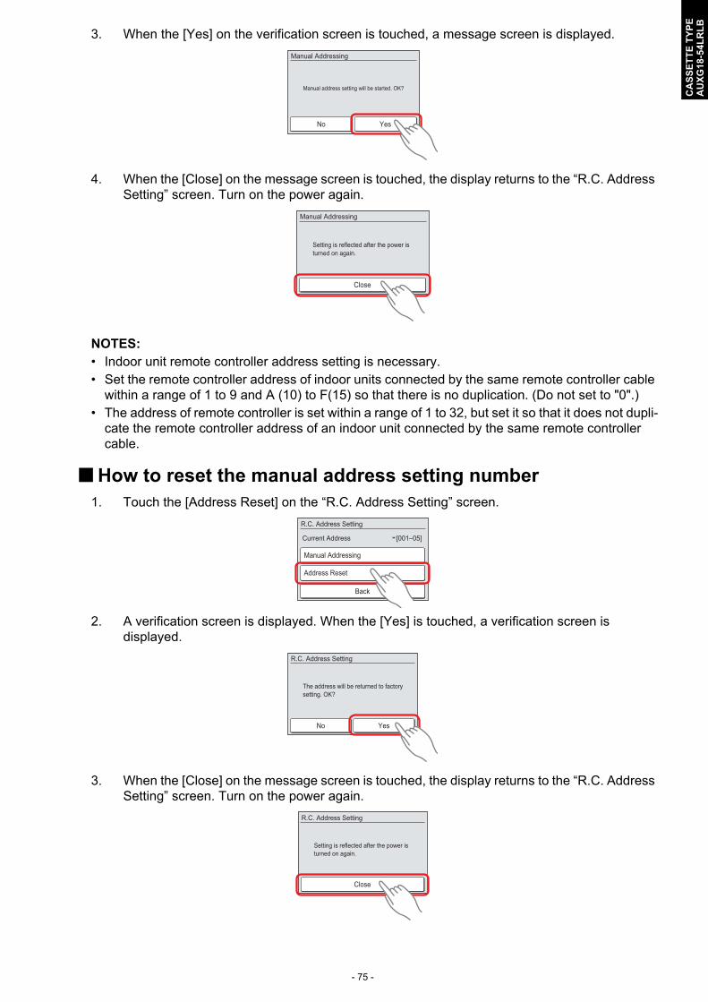
- 75 -
CA
SS
ET
TE
TY
PE
AU
XG
18-5
4LR
LB
3. When the [Yes] on the verification screen is touched, a message screen is displayed.
4. When the [Close] on the message screen is touched, the display returns to the “R.C. Address Setting” screen. Turn on the power again.
NOTES: • Indoor unit remote controller address setting is necessary.• Set the remote controller address of indoor units connected by the same remote controller cable
within a range of 1 to 9 and A (10) to F(15) so that there is no duplication. (Do not set to "0".)• The address of remote controller is set within a range of 1 to 32, but set it so that it does not dupli-
cate the remote controller address of an indoor unit connected by the same remote controller cable.
How to reset the manual address setting number1. Touch the [Address Reset] on the “R.C. Address Setting” screen.
2. A verification screen is displayed. When the [Yes] is touched, a verification screen is displayed.
3. When the [Close] on the message screen is touched, the display returns to the “R.C. Address Setting” screen. Turn on the power again.
No Yes
Manual Addressing
Manual address setting will be started. OK?
Setting is reflected after the power is turned on again.
Manual Addressing
Close
[001–05]
R.C. Address Setting
Current Address
Back
Manual Addressing
Address Reset
No Yes
R.C. Address Setting
The address will be returned to factory setting. OK?
Setting is reflected after the power is turned on again.
R.C. Address Setting
Close
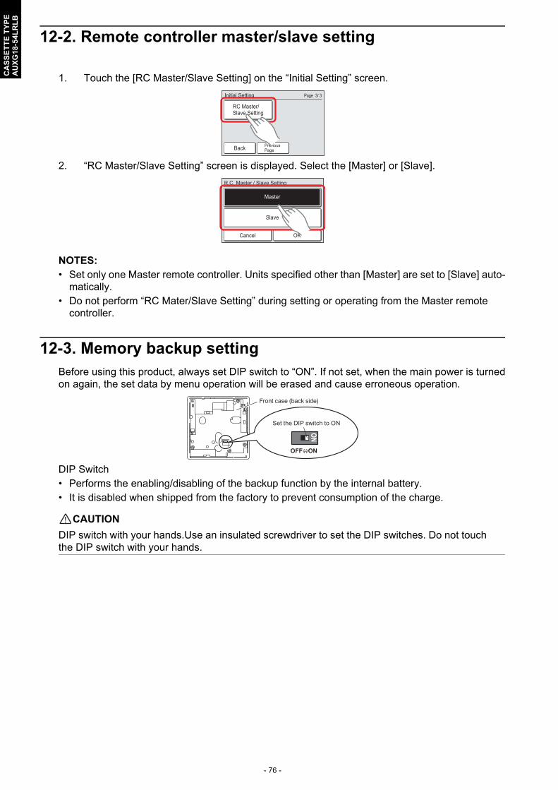
- 76 -
CA
SS
ET
TE
TY
PE
AU
XG
18-5
4LR
LB
12-2. Remote controller master/slave setting
1. Touch the [RC Master/Slave Setting] on the “Initial Setting” screen.
2. “RC Master/Slave Setting” screen is displayed. Select the [Master] or [Slave].
NOTES: • Set only one Master remote controller. Units specified other than [Master] are set to [Slave] auto-
matically.• Do not perform “RC Mater/Slave Setting” during setting or operating from the Master remote
controller.
12-3. Memory backup settingBefore using this product, always set DIP switch to “ON”. If not set, when the main power is turnedon again, the set data by menu operation will be erased and cause erroneous operation.
DIP Switch• Performs the enabling/disabling of the backup function by the internal battery.• It is disabled when shipped from the factory to prevent consumption of the charge.
! CAUTION
DIP switch with your hands.Use an insulated screwdriver to set the DIP switches. Do not touchthe DIP switch with your hands.
Back PreviousPage
Page 3/ 3Initial Setting
RC Master/Slave Setting
R.C. Master / Slave Setting
Cancel OK
Master
Slave
Front case (back side)
Set the DIP switch to ON
OFF ON
ON

- 77 -
CA
SS
ET
TE
TY
PE
AU
XG
18-5
4LR
LB
13. Optional parts
13-1. Controllers
NOTE: Available functions may differ by the remote controller. For details, refer to the operation manual.
Exterior Part name Model name Summary
Wired remote controller
UTY-RNRYZ1
Easy finger touch operation with LCD panel. Backlit LCD enables easy operation in a dark room.Wire type: Non-polar 2-wire
Wired remote controller
UTY-RLRY
High visibility and easy operation.Room temperature can be accurately controlled using the built-in thermo sensor.Wire type: Non-polar 2-wire
Wired remote controller
UTY-RVNYM
Large and full-dot liquid crystal screen, wide and large keys easy to press, user-intuitive arrow key.Wire type: Polar 3-wire
Wired remote controller
UTY-RNNYM
Room temperature can be controlled by detecting the temperature accurately with built-in thermo sensor.Wire type: Polar 3-wire
Simple remote controller
UTY-RSNYM
Compact remote controller concentrates on the basic functions such as Start/Stop, fan control, temperature setting, and operation mode.Wire type: Polar 3-wire
IR receiver unit UTY-LBTYCUnit control is performed by wireless remote controller.
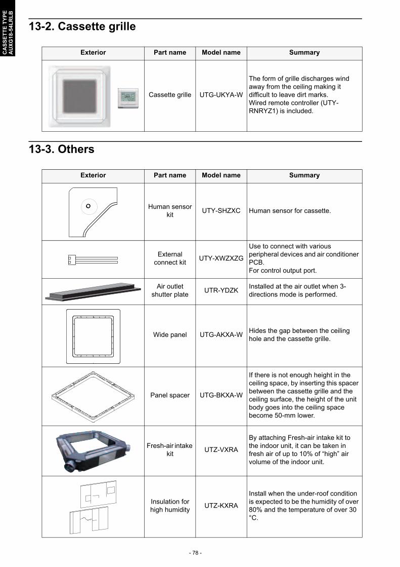
- 78 -
CA
SS
ET
TE
TY
PE
AU
XG
18-5
4LR
LB
13-2. Cassette grille
13-3. Others
Exterior Part name Model name Summary
Cassette grille UTG-UKYA-W
The form of grille discharges wind away from the ceiling making it difficult to leave dirt marks.Wired remote controller (UTY-RNRYZ1) is included.
Exterior Part name Model name Summary
Human sensor kit
UTY-SHZXC Human sensor for cassette.
External connect kit
UTY-XWZXZG
Use to connect with various peripheral devices and air conditioner PCB.For control output port.
Air outlet shutter plate
UTR-YDZKInstalled at the air outlet when 3-directions mode is performed.
Wide panel UTG-AKXA-WHides the gap between the ceiling hole and the cassette grille.
Panel spacer UTG-BKXA-W
If there is not enough height in the ceiling space, by inserting this spacer between the cassette grille and the ceiling surface, the height of the unit body goes into the ceiling space become 50-mm lower.
Fresh-air intake kit
UTZ-VXRA
By attaching Fresh-air intake kit to the indoor unit, it can be taken in fresh air of up to 10% of “high” air volume of the indoor unit.
Insulation for high humidity
UTZ-KXRA
Install when the under-roof condition is expected to be the humidity of over 80% and the temperature of over 30 °C.

- 79 -
CA
SS
ET
TE
TY
PE
AU
XG
18-5
4LR
LB
External input and output PCB
UTY-XCSXUse to connect with external devices and air conditioner PCB.
External input and output PCB
boxUTZ-GXRA
For installing the External input and output PCB.
Exterior Part name Model name Summary

- 80 -
CA
SS
ET
TE
TY
PE
AU
XG
18-5
4LR
LB
Part 2. OUTDOOR UNITSINGLE TYPE:AOYG18LBCAAOYG24LBCAAOYG30LBTAAOYG36LBTAAOYG45LBTAAOYG54LBTA

- 82 -
OU
TD
OO
R U
NIT
AO
YG
18-5
4LB
1. Specifications
1-1. Models: AOYG18LBCA and AOYG24LBCA
Type Inverter heat pump
Model name AOYG18LBCA AOYG24LBCA
Power supply 230 V ~ 50 Hz
Available voltage range 198—264 V
Starting current A 6.6 9.6
Fan
Airflow rateCooling
m3/h1,900 2,460
Heating 1,700 2,340
Type × Q'ty Propeller × 1
Motor output W 49
Sound pressure level *1Cooling
dB (A)51 55
Heating 50 56
Sound power levelCooling
dB (A)64 68
Heating 62 68
Heat exchanger type
Dimensions(H × W × D) mm
Main: 588 × 881 × 18.2Sub: 525 × 580 × 18.2
Fin pitch 1.45
Rows × StagesMain: 2 × 28Sub: 1 × 26
Pipe type Copper
Fin typeType (Material) Corrugate (Aluminum)
Surface treatment Corrosion resistance
CompressorType × Q'ty Twin rotary × 1
Motor output W 1,100
RefrigerantType (Global Warming Potential) R410A (1975)
Charge g 1,800
Refrigerant oilType RB68
Amount cm3 600
EnclosureMaterial Steel sheet
ColorBeige
Approximate color of MUNSELL 10YR7.5/1.0
Dimensions(H × W × D)
Netmm
620 × 790 × 290
Gross 713 × 945 × 395
WeightNet
kg41
Gross 45
Connection pipe
SizeLiquid
mm(in)Ø 6.35 (Ø 1/4)
Gas Ø 12.70(Ø 1/2) Ø 15.88 (Ø 5/8)
Method Flare
Pre-charge length
m
15
Max. length 30
Max. height difference 20
Operation rangeCooling
°C-15 to 46
Heating -15 to 24
Drain hoseMaterial LDPE
Size mm Ø 13.0 (I.D.), Ø 16.0 to Ø 16.7 (O.D.)
NOTES: Specifications are based on the following conditions:
–Cooling: Indoor temperature of 27 °CDB/19 °CWB, and outdoor temperature of 35 °CDB/24 °CWB.–Heating: Indoor temperature of 20 °CDB/15 °CWB, and outdoor temperature of 7 °CDB/6 °CWB.–Pipe length: 5 m, Height difference: 0 m.
Protective function might work when using it outside the operation range.*1: Sound pressure level
–Measured values in manufacturer’s anechoic chamber.–Because of the surrounding sound environment, the sound levels measured in actual installation conditions might be higher than the specified values here.

- 83 -
OU
TD
OO
R U
NIT
AO
YG
18-5
4LB
1-2. Models: AOYG30LBTA and AOYG36LBTA
Type Inverter heat pump
Model name AOYG30LBTA AOYG36LBTA
Power supply 230 V ~ 50 Hz
Available voltage range 198—264 V
Starting current A 12.2 13.0
Fan
Airflow rateCooling
m3/h3,600 3,800
Heating 3,600 3,800
Type × Q'ty Propeller × 1
Motor output W 100
Sound pressure level *1Cooling
dB (A)53 54
Heating 55 55
Sound power levelCooling
dB (A)67 68
Heating 69 70
Heat exchanger type
Dimensions(H × W × D) mm
798 × 900 × 36.4
Fin pitch 1.30
Rows × Stages 2 × 38
Pipe type Copper
Fin typeType (Material) Corrugate (Aluminum)
Surface treatment Corrosion resistance (Blue fin)
CompressorType × Q'ty Twin rotary × 1
Motor output W 2,100
RefrigerantType (Global Warming Potential) R410A (1975)
Charge g 2,100
Refrigerant oilType RmM68AF
Amount cm3 800
EnclosureMaterial Steel sheet
ColorBeige
Approximate color of MUNSELL 10YR7.5/1.0
Dimensions(H × W × D)
Netmm
830 × 900 × 330
Gross 1,000 × 1,050 × 445
WeightNet
kg61
Gross 69
Connection pipe
SizeLiquid
mm(in)Ø 9.52 (Ø 3/8)
Gas Ø 15.88 (Ø 5/8)
Method Flare
Pre-charge length
m
20
Max. length 50
Max. height difference 30
Operation rangeCooling
°C-15 to 46
Heating -15 to 24
Drain hoseMaterial LDPE
Size mm Ø 13.0 (I.D.), Ø 16.0 to Ø 16.7 (O.D.)
NOTES: Specifications are based on the following conditions:
–Cooling: Indoor temperature of 27 °CDB/19 °CWB, and outdoor temperature of 35 °CDB/24 °CWB.–Heating: Indoor temperature of 20 °CDB/15 °CWB, and outdoor temperature of 7 °CDB/6 °CWB.–Pipe length: 5 m, Height difference: 0 m.
Protective function might work when using it outside the operation range.*1: Sound pressure level
–Measured values in manufacturer’s anechoic chamber.–Because of the surrounding sound environment, the sound levels measured in actual installation conditions might be higher than the specified values here.
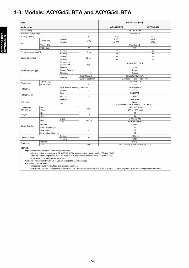
- 84 -
OU
TD
OO
R U
NIT
AO
YG
18-5
4LB
1-3. Models: AOYG45LBTA and AOYG54LBTA
Type Inverter heat pump
Model name AOYG45LBTA AOYG54LBTA
Power supply 230 V ~ 50 Hz
Available voltage range 198—264 V
Starting current A 16.8 20.0
Fan
Airflow rateCooling
m3/h6,750 6,750
Heating 6,200 6,850
Type × Q'ty Propeller × 2
Motor output W 100
Sound pressure level *1Cooling
dB (A)55 55
Heating 55 57
Sound power levelCooling
dB (A)68 69
Heating 68 71
Heat exchanger type
Dimensions(H × W × D) mm
1,260 × 900 × 36.4
Fin pitch 1.30
Rows × Stages 2 × 60
Pipe type Copper
Fin typeType (Material) Corrugate (Aluminum)
Surface treatment Corrosion resistance (Blue fin)
CompressorType × Q'ty Twin rotary × 1
Motor output W 2,100
RefrigerantType (Global Warming Potential) R410A (1975)
Charge g 3,350
Refrigerant oilType RmM68AF
Amount cm3 800
EnclosureMaterial Steel sheet
ColorBeige
Approximate color of MUNSELL 10YR7.5/1.0
Dimensions(H × W × D)
Netmm
1,290 × 900 × 330
Gross 1,460 × 1,050 × 445
WeightNet
kg86
Gross 95
Connection pipe
SizeLiquid
mm(in)Ø 9.52 (Ø 3/8)
Gas Ø 15.88 (Ø 5/8)
Method Flare
Pre-charge length
m
20
Max. length 50
Max. height difference 30
Operation rangeCooling
°C-15 to 46
Heating -15 to 24
Drain hoseMaterial LDPE
Size mm Ø 13.0 (I.D.), Ø 16.0 to Ø 16.7 (O.D.)
NOTES: Specifications are based on the following conditions:
–Cooling: Indoor temperature of 27 °CDB/19 °CWB, and outdoor temperature of 35 °CDB/24 °CWB.–Heating: Indoor temperature of 20 °CDB/15 °CWB, and outdoor temperature of 7 °CDB/6 °CWB.–Pipe length: 5 m, Height difference: 0 m.
Protective function might work when using it outside the operation range.*1: Sound pressure level
–Measured values in manufacturer’s anechoic chamber.–Because of the surrounding sound environment, the sound levels measured in actual installation conditions might be higher than the specified values here.

- 85 -
OU
TD
OO
R U
NIT
AO
YG
18-5
4LB
2. Dimensions
2-1. Models: AOYG18LBCA and AOYG24LBCA
Pitch of bolts for installation
353
45.4
320
395
540 125
Drain port Ø20
20 790
620
20
62 290
Unit: mm
Top view
Front view Side view
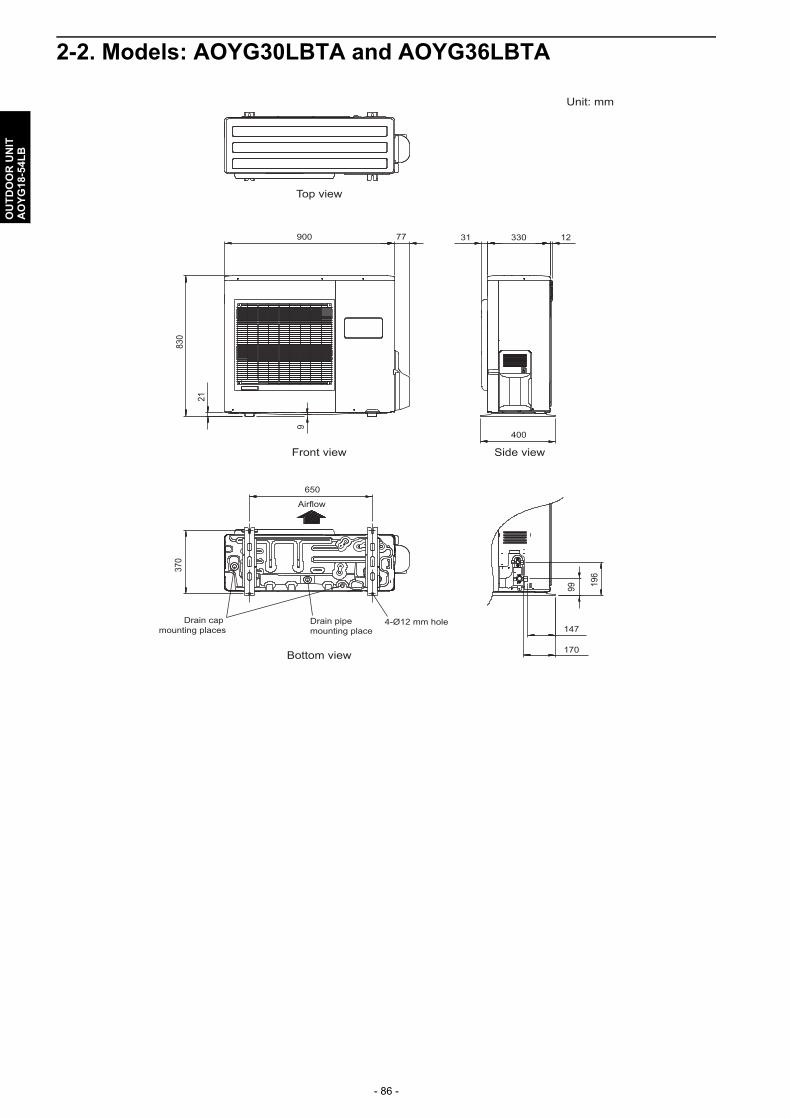
- 86 -
OU
TD
OO
R U
NIT
AO
YG
18-5
4LB
2-2. Models: AOYG30LBTA and AOYG36LBTA
900
650
830
370
99 196
21
9
77 31 330
400
170
147
12
Top view
Front view Side view
Bottom view
Airflow
4-Ø12 mm holeDrain cap mounting places
Drain pipe mounting place
Unit: mm

- 87 -
OU
TD
OO
R U
NIT
AO
YG
18-5
4LB
2-3. Models: AOYG45LBTA and AOYG54LBTA
330
31
650 119132
( 370
)
38 (L
iqui
d)
4566
46 ( G
as)
1290
900
21
9
89 21
952550
543
( Gas
val
ve)
540
(Liq
uid
valv
e)
992
21
33031 12
555012
0
509516
7
156
112
21 67
188
265
302
400
51.5440
625
Ø28
(Cab
le po
rt)
Ø28
(Cab
le po
rt)
Ø28 (Cable port)
Ø28
(Cable port)
Ø28 (Cable port)Ø28 (Cable port)
Pipe port
A
Pipe portPipe port
Top view
Front view
Bottom view
Side view
Detail A
Rear view
403-way valve
(Gas)
3-way valve(Liquid)
Terminal blocks
1446
1654
87131
Pipe & cable port
Unit: mm
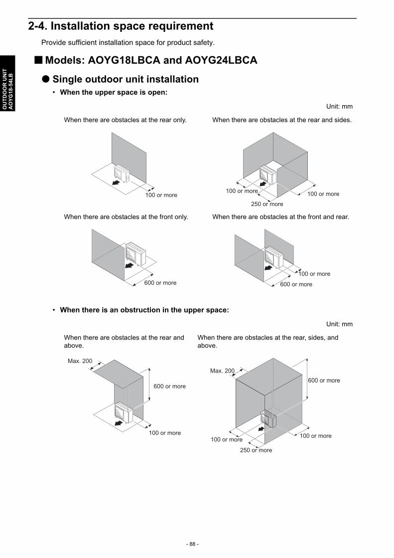
- 88 -
OU
TD
OO
R U
NIT
AO
YG
18-5
4LB
2-4. Installation space requirementProvide sufficient installation space for product safety.
Models: AOYG18LBCA and AOYG24LBCA
Single outdoor unit installation• When the upper space is open:
• When there is an obstruction in the upper space:
Unit: mm
When there are obstacles at the rear only. When there are obstacles at the rear and sides.
When there are obstacles at the front only. When there are obstacles at the front and rear.
Unit: mm
When there are obstacles at the rear and above.
When there are obstacles at the rear, sides, and above.
100 or more250 or more
100 or more100 or more
600 or more 600 or more
100 or more
100 or more
Max. 200
600 or more600 or more
100 or more
250 or more
100 or more
Max. 200

- 89 -
OU
TD
OO
R U
NIT
AO
YG
18-5
4LB
Multiple outdoor unit installation• When the upper space is open:
• When there is an obstruction in the upper space:
Unit: mm
When there are obstacles at the rear only. When there are obstacles at the front only.
When there are obstacles at the front and rear.
Unit: mm
When there are obstacles at the rear and above.
200or more
1,000 or more
200 or more1,000 or more
1,500 or more
200 or more
Max. 300

- 90 -
OU
TD
OO
R U
NIT
AO
YG
18-5
4LB
Outdoor unit installation in multi-row
NOTES: • If the space is larger than stated above, the condition will be the same as when there is no
obstacle.• Height above the floor level should be 50 mm or more.• When installing the outdoor unit, be sure to open the front and left side to obtain better operation
efficiency.
! CAUTION
• When the outdoor temperature is 0 °C or less, do not use the accessory drain pipe and drain cap. If the drain pipe and drain cap are used, the drain water in the pipe may freeze in extremely cold climate. (For reverse cycle model only.)
• In area with heavy snowfall, if the inlet and outlet of the outdoor unit is blocked with snow, it might become difficult to get warm, and it is likely to cause product malfunction. Construct a canopy and a pedestal, or place the unit on a high stand that is locally installed.
Unit: mm
Single parallel unit arrangement Multiple parallel unit arrangement
100 or more
200 or more500 or more
1,000 or more200 or more
400 or more1,000 or more
2,000 or more
200 or more
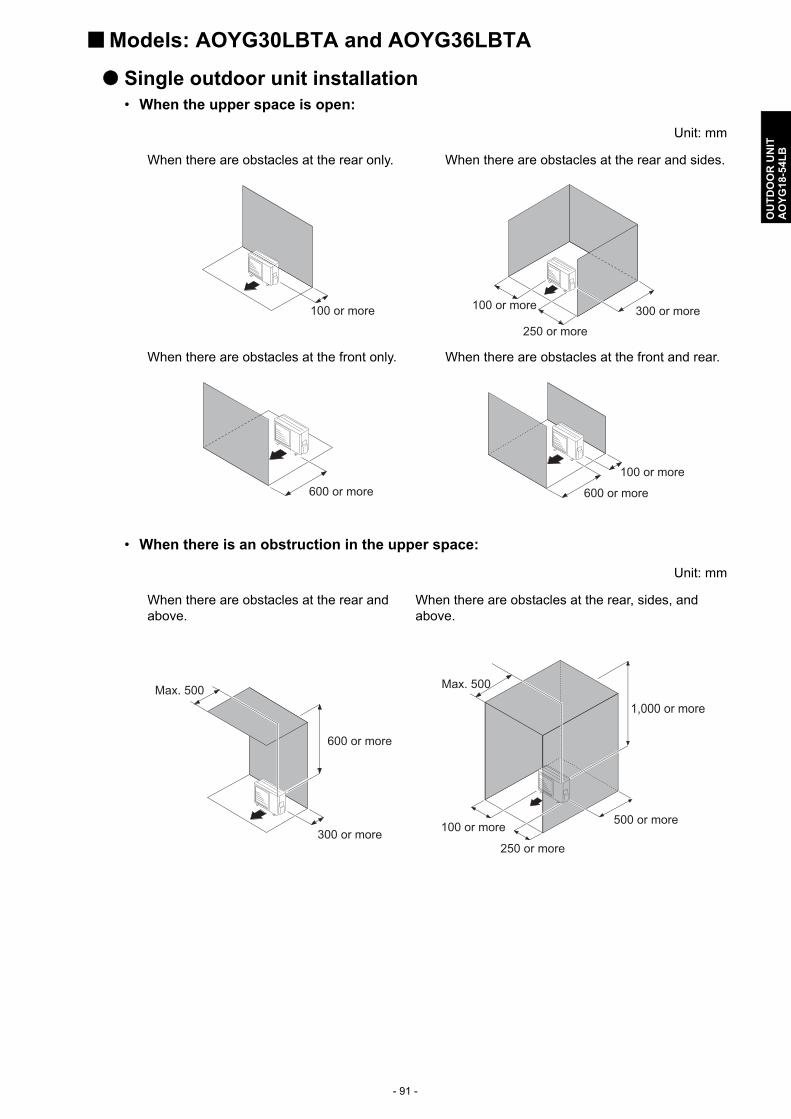
- 91 -
OU
TD
OO
R U
NIT
AO
YG
18-5
4LB
Models: AOYG30LBTA and AOYG36LBTA
Single outdoor unit installation• When the upper space is open:
• When there is an obstruction in the upper space:
Unit: mm
When there are obstacles at the rear only. When there are obstacles at the rear and sides.
When there are obstacles at the front only. When there are obstacles at the front and rear.
Unit: mm
When there are obstacles at the rear and above.
When there are obstacles at the rear, sides, and above.
100 or more
250 or more
300 or more100 or more
600 or more 600 or more
100 or more
300 or more
Max. 500
600 or more
1,000 or more
100 or more
250 or more
500 or more
Max. 500
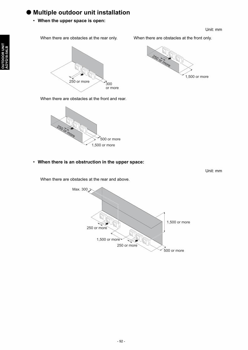
- 92 -
OU
TD
OO
R U
NIT
AO
YG
18-5
4LB
Multiple outdoor unit installation• When the upper space is open:
• When there is an obstruction in the upper space:
Unit: mm
When there are obstacles at the rear only. When there are obstacles at the front only.
When there are obstacles at the front and rear.
Unit: mm
When there are obstacles at the rear and above.
300250 or more
or more
1,500 or more
250 or more
500 or more1,500 or more
250 or more
1,500 or more
500 or more250 or more
250 or more
Max. 300
1,500 or more

- 93 -
OU
TD
OO
R U
NIT
AO
YG
18-5
4LB
Outdoor unit installation in multi-row
NOTES: • If the space is larger than stated above, the condition will be the same as when there is no
obstacle.• Height above the floor level should be 50 mm or more.• When installing the outdoor unit, be sure to open the front and left side to obtain better operation
efficiency.
! CAUTION
• When the outdoor temperature is 0 °C or less, do not use the accessory drain pipe and drain cap. If the drain pipe and drain cap are used, the drain water in the pipe may freeze in extremely cold climate. (For reverse cycle model only.)
• In area with heavy snowfall, if the inlet and outlet of the outdoor unit is blocked with snow, it might become difficult to get warm, and it is likely to cause product malfunction. Construct a canopy and a pedestal, or place the unit on a high stand that is locally installed.
Unit: mm
Single parallel unit arrangement Multiple parallel unit arrangement
150 or more
600 or more1,000 or more
2,000 or more500 or more
600 or more1,500 or more
250 or more3,000 or more
250 or more
1,500 or more500 or more
250 or more
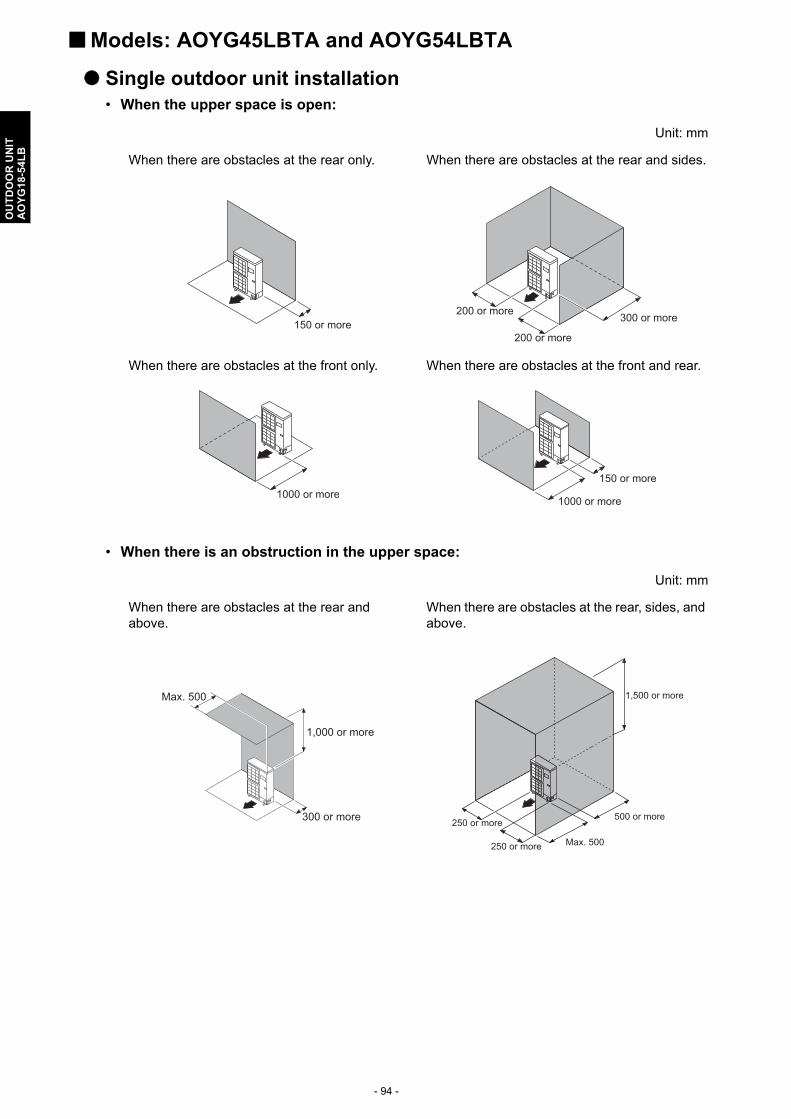
- 94 -
OU
TD
OO
R U
NIT
AO
YG
18-5
4LB
Models: AOYG45LBTA and AOYG54LBTA
Single outdoor unit installation• When the upper space is open:
• When there is an obstruction in the upper space:
Unit: mm
When there are obstacles at the rear only. When there are obstacles at the rear and sides.
When there are obstacles at the front only. When there are obstacles at the front and rear.
Unit: mm
When there are obstacles at the rear and above.
When there are obstacles at the rear, sides, and above.
150 or more200 or more
200 or more
300 or more
1000 or more 1000 or more
150 or more
300 or more
Max. 500
1,000 or more
Max. 500
500 or more
250 or more
250 or more
1,500 or more
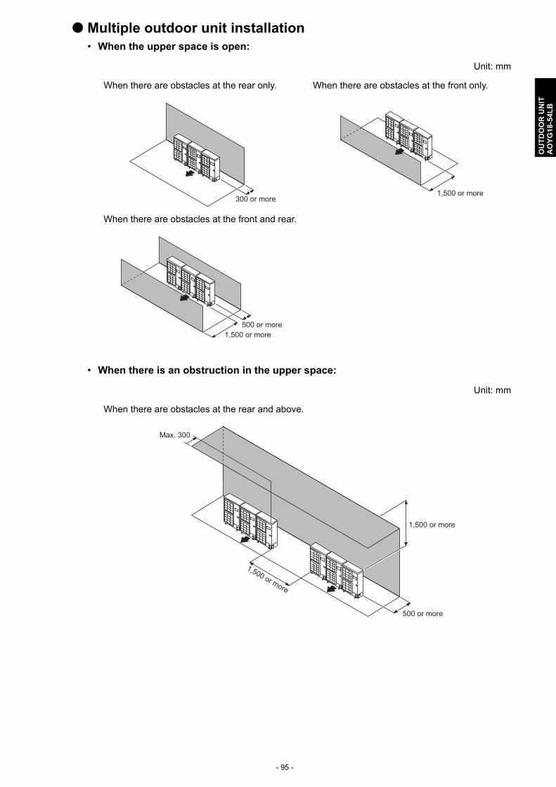
- 95 -
OU
TD
OO
R U
NIT
AO
YG
18-5
4LB
Multiple outdoor unit installation• When the upper space is open:
• When there is an obstruction in the upper space:
Unit: mm
When there are obstacles at the rear only. When there are obstacles at the front only.
When there are obstacles at the front and rear.
Unit: mm
When there are obstacles at the rear and above.
300 or more1,500 or more
500 or more 1,500 or more
1,500 or more
1,500 or more
500 or more
Max. 300
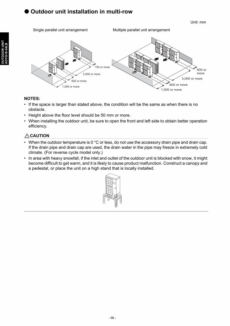
- 96 -
OU
TD
OO
R U
NIT
AO
YG
18-5
4LB
Outdoor unit installation in multi-row
NOTES: • If the space is larger than stated above, the condition will be the same as when there is no
obstacle.• Height above the floor level should be 50 mm or more.• When installing the outdoor unit, be sure to open the front and left side to obtain better operation
efficiency.
! CAUTION
• When the outdoor temperature is 0 °C or less, do not use the accessory drain pipe and drain cap. If the drain pipe and drain cap are used, the drain water in the pipe may freeze in extremely cold climate. (For reverse cycle model only.)
• In area with heavy snowfall, if the inlet and outlet of the outdoor unit is blocked with snow, it might become difficult to get warm, and it is likely to cause product malfunction. Construct a canopy and a pedestal, or place the unit on a high stand that is locally installed.
Unit: mm
Single parallel unit arrangement Multiple parallel unit arrangement
1,000 or more
2,000 or more
600 or more
150 or more
3,000 or more
600 or more1,500 or more
500 or more
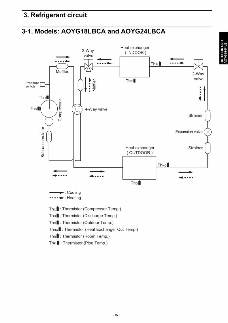
- 97 -
OU
TD
OO
R U
NIT
AO
YG
18-5
4LB
3. Refrigerant circuit
3-1. Models: AOYG18LBCA and AOYG24LBCA
2-Wayvalve
Strainer
Strainer
3-Wayvalve
Muffler
4-Way valve
Expansion valve
Heat exchanger( INDOOR )
Heat exchanger( OUTDOOR )
Com
pres
sor
: Cooling: Heating
Muf
fler
Pressureswitch
Sub
-acc
umul
ator
ThC
ThR
ThD
ThPI
ThO
ThHO
ThC : Thermistor (Compressor Temp.): Thermistor (Discharge Temp.): Thermistor (Outdoor Temp.): Thermistor (Heat Exchanger Out Temp.)
ThD
ThO
ThHO
: Thermistor (Room Temp.): Thermistor (Pipe Temp.)
ThR
ThPI
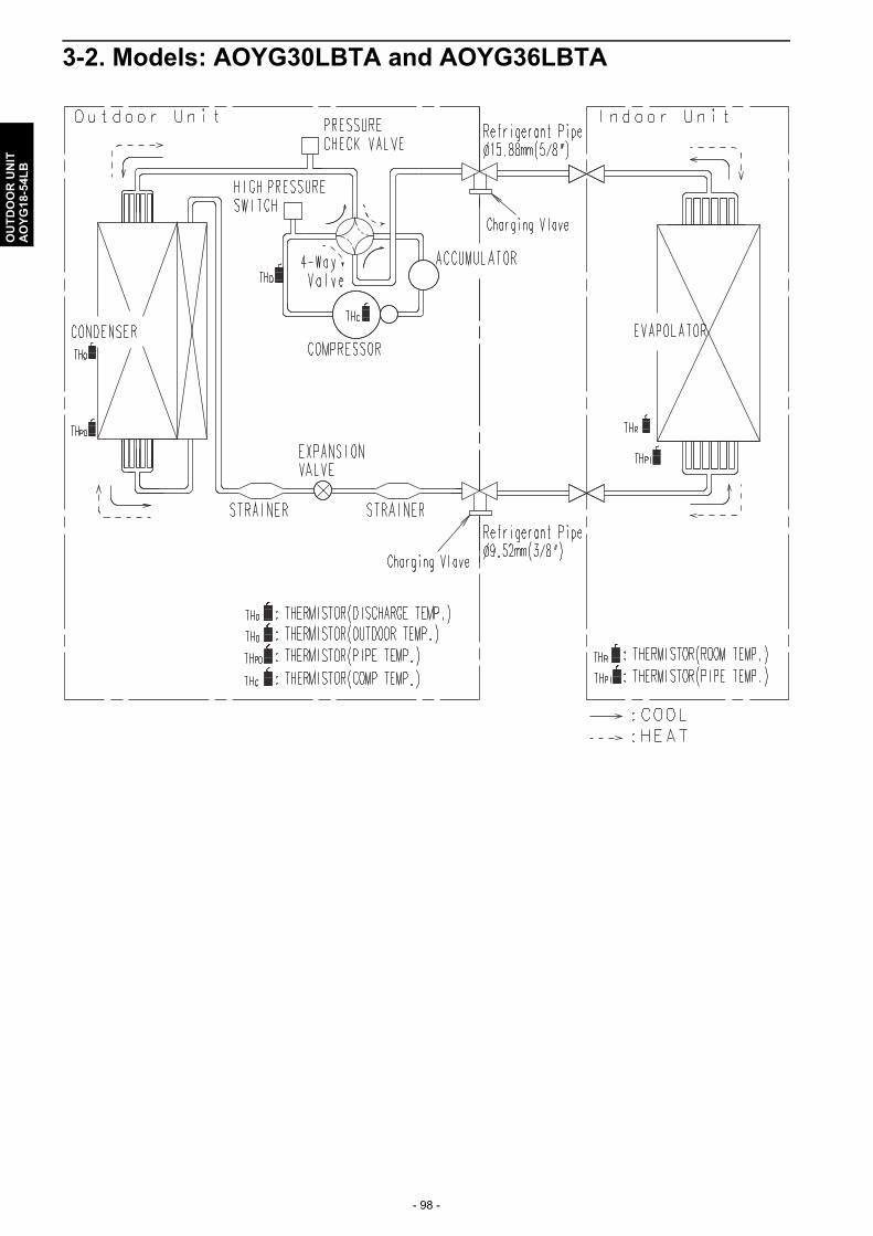
- 98 -
OU
TD
OO
R U
NIT
AO
YG
18-5
4LB
3-2. Models: AOYG30LBTA and AOYG36LBTA

- 99 -
OU
TD
OO
R U
NIT
AO
YG
18-5
4LB
3-3. Models: AOYG45LBTA and AOYG54LBTA
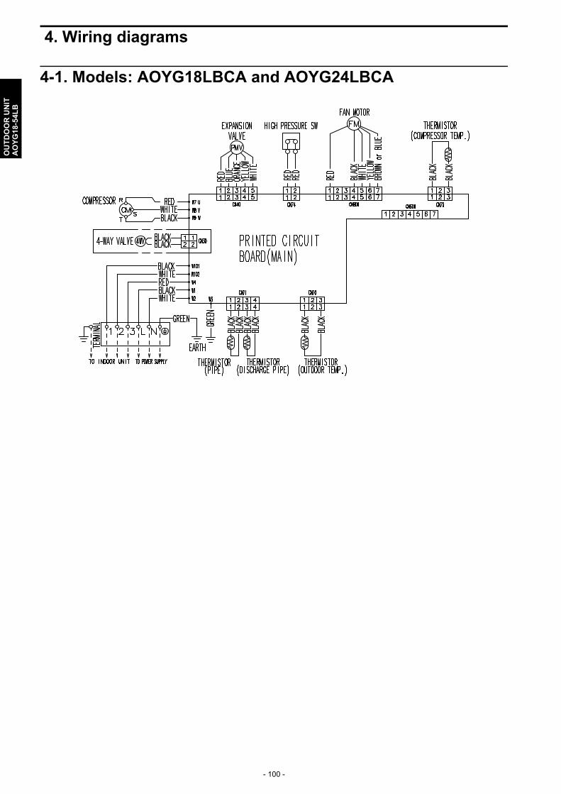
- 100 -
OU
TD
OO
R U
NIT
AO
YG
18-5
4LB
4. Wiring diagrams
4-1. Models: AOYG18LBCA and AOYG24LBCA
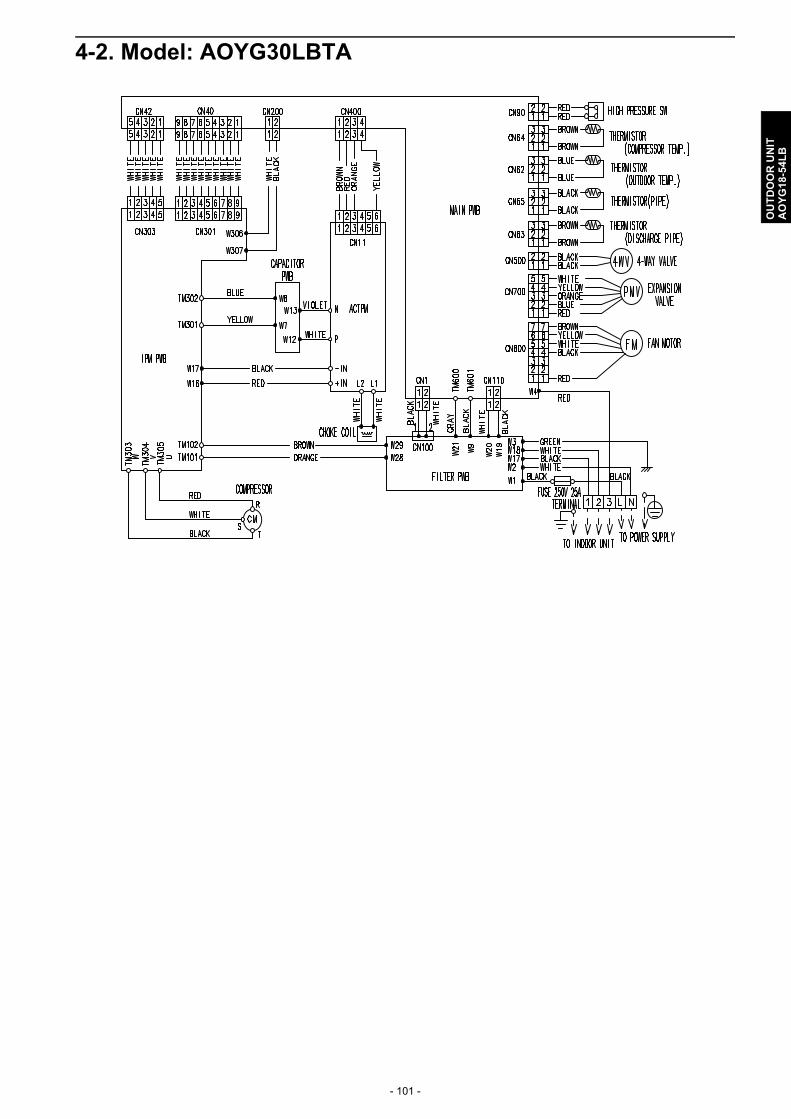
- 101 -
OU
TD
OO
R U
NIT
AO
YG
18-5
4LB
4-2. Model: AOYG30LBTA

- 102 -
OU
TD
OO
R U
NIT
AO
YG
18-5
4LB
4-3. Model: AOYG36LBTA
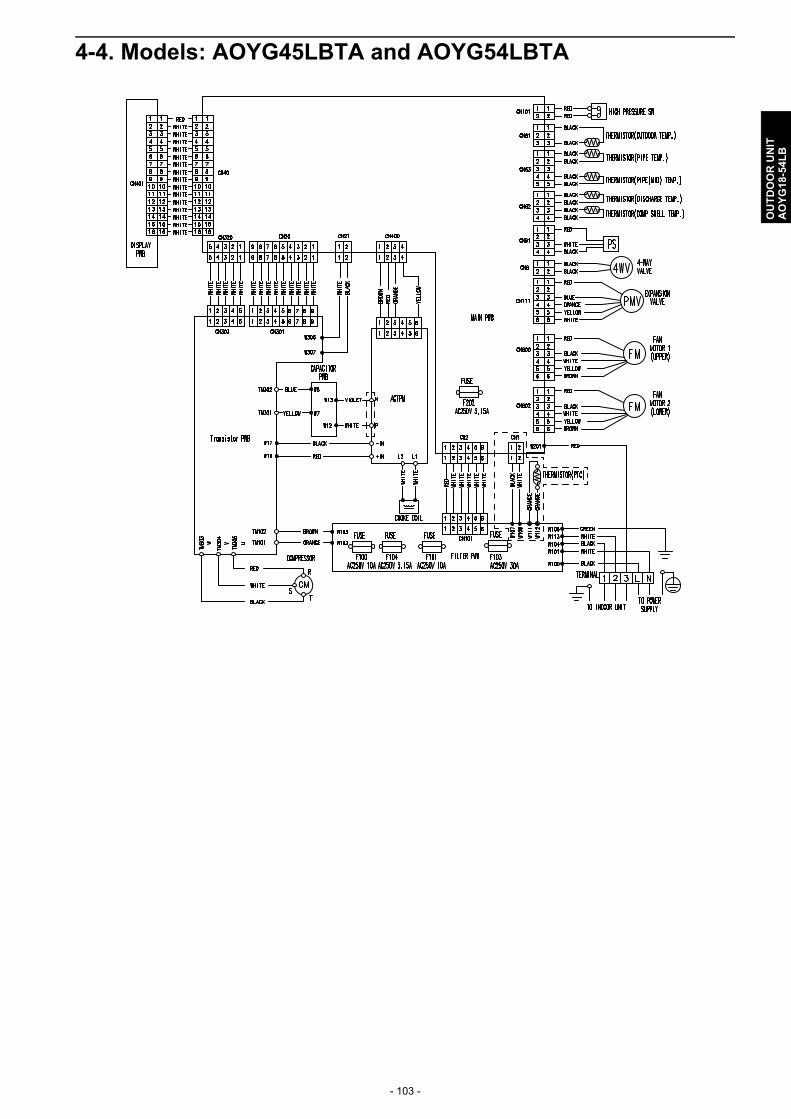
- 103 -
OU
TD
OO
R U
NIT
AO
YG
18-5
4LB
4-4. Models: AOYG45LBTA and AOYG54LBTA

- 104 -
OU
TD
OO
R U
NIT
AO
YG
18-5
4LB
5. Capacity compensation rate for pipe length and height difference
5-1. Model: AOYG18LBCA
NOTE: Values mentioned in the table are calculated based on the maximum capacity.
COOLINGPipe length (m)
5 7.5 10 20 30
Hei
ght d
iffer
ence
H (
m)
Indoor unit is higher than outdoor unit *1
20 - - - 0.952 0.951
10 - - 0.980 0.968 0.966
7.5 - 0.988 0.984 0.972 0.970
5 0.995 0.992 0.988 0.976 0.974
0 1.003 1.000 0.996 0.983 0.982
Indoor unit is lower than outdoor unit *2
-5 1.003 1.000 0.996 0.983 0.982
-7.5 - 1.000 0.996 0.983 0.982
-10 - - 0.996 0.983 0.982
-20 - - - 0.983 0.982
HEATINGPipe length (m)
5 7.5 10 20 30
Hei
ght
diff
ere
nce
H (
m)
Indoor unit is higher than outdoor unit *1
20 - - - 0.954 0.908
10 - - 0.998 0.954 0.908
7.5 - 1.000 0.998 0.954 0.908
5 0.989 1.000 0.998 0.954 0.908
0 0.989 1.000 0.998 0.954 0.908
Indoor unit is lower than outdoor unit *2
-5 0.984 0.995 0.993 0.950 0.903
-7.5 - 0.993 0.991 0.947 0.901
-10 - - 0.988 0.945 0.899
-20 - - - 0.935 0.890
Height difference HIndoor unit is higher than outdoor unit *1 Indoor unit is lower than outdoor unit *2
Indoor unit
Indoor unit
Connection pipe
Outdoor unit
Outdoor unit
Connection pipe
H H
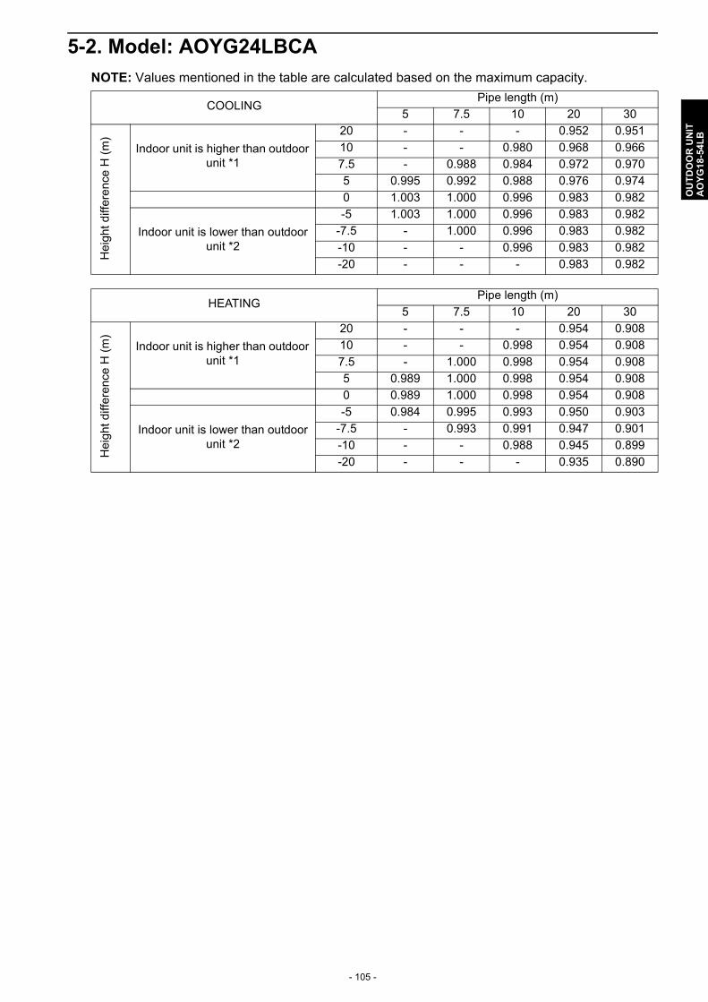
- 105 -
OU
TD
OO
R U
NIT
AO
YG
18-5
4LB
5-2. Model: AOYG24LBCA
NOTE: Values mentioned in the table are calculated based on the maximum capacity.
COOLINGPipe length (m)
5 7.5 10 20 30H
eig
ht d
iffe
renc
e H
(m
)
Indoor unit is higher than outdoor unit *1
20 - - - 0.952 0.951
10 - - 0.980 0.968 0.966
7.5 - 0.988 0.984 0.972 0.970
5 0.995 0.992 0.988 0.976 0.974
0 1.003 1.000 0.996 0.983 0.982
Indoor unit is lower than outdoor unit *2
-5 1.003 1.000 0.996 0.983 0.982
-7.5 - 1.000 0.996 0.983 0.982
-10 - - 0.996 0.983 0.982
-20 - - - 0.983 0.982
HEATINGPipe length (m)
5 7.5 10 20 30
Hei
ght
diff
ere
nce
H (
m)
Indoor unit is higher than outdoor unit *1
20 - - - 0.954 0.908
10 - - 0.998 0.954 0.908
7.5 - 1.000 0.998 0.954 0.908
5 0.989 1.000 0.998 0.954 0.908
0 0.989 1.000 0.998 0.954 0.908
Indoor unit is lower than outdoor unit *2
-5 0.984 0.995 0.993 0.950 0.903
-7.5 - 0.993 0.991 0.947 0.901
-10 - - 0.988 0.945 0.899
-20 - - - 0.935 0.890

- 106 -
OU
TD
OO
R U
NIT
AO
YG
18-5
4LB
5-3. Model: AOYG30LBTA
NOTE: Values mentioned in the table are calculated based on the maximum capacity.
COOLINGPipe length (m)
5 7.5 10 20 30 40 50
He
igh
t di
ffer
ence
H (
m) Indoor unit is higher than
outdoor unit *1
30 - - - - 0.908 0.894 0.876
20 - - - 0.935 0.923 0.909 0.891
10 - - 0.968 0.951 0.938 0.924 0.906
7.5 - 0.982 0.972 0.954 0.942 0.928 0.909
5 0.992 0.986 0.976 0.958 0.946 0.932 0.913
0 1.000 0.994 0.983 0.966 0.954 0.939 0.920
Indoor unit is lower than outdoor unit *2
-5 1.000 0.994 0.983 0.966 0.954 0.939 0.920
-7.5 - 0.994 0.983 0.966 0.954 0.939 0.920
-10 - - 0.983 0.966 0.954 0.939 0.920
-20 - - - 0.966 0.954 0.939 0.920
-30 - - - - 0.954 0.939 0.920
HEATINGPipe length (m)
5 7.5 10 20 30 40 50
Hei
ght
diff
ere
nce
H (
m) Indoor unit is higher than
outdoor unit *1
30 - - - - 0.931 0.914 0.899
20 - - - 0.954 0.931 0.914 0.899
10 - - 0.990 0.954 0.931 0.914 0.899
7.5 - 0.991 0.990 0.954 0.931 0.914 0.899
5 1.000 0.991 0.990 0.954 0.931 0.914 0.899
0 1.000 0.991 0.990 0.954 0.931 0.914 0.899
Indoor unit is lower than outdoor unit *2
-5 0.995 0.986 0.986 0.949 0.926 0.909 0.895
-7.5 - 0.983 0.983 0.946 0.924 0.907 0.892
-10 - - 0.981 0.944 0.921 0.904 0.890
-20 - - - 0.935 0.912 0.895 0.881
-30 - - - - 0.903 0.886 0.872
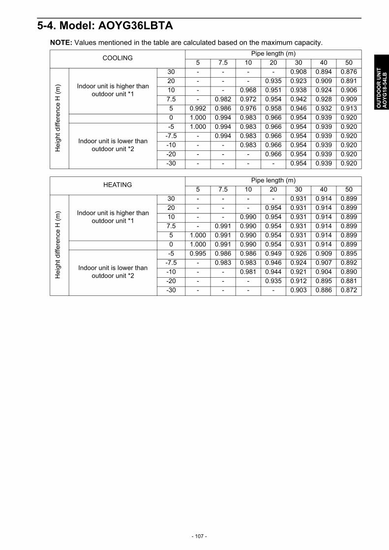
- 107 -
OU
TD
OO
R U
NIT
AO
YG
18-5
4LB
5-4. Model: AOYG36LBTA
NOTE: Values mentioned in the table are calculated based on the maximum capacity.
COOLINGPipe length (m)
5 7.5 10 20 30 40 50H
eig
ht
diff
eren
ce H
(m
) Indoor unit is higher than outdoor unit *1
30 - - - - 0.908 0.894 0.876
20 - - - 0.935 0.923 0.909 0.891
10 - - 0.968 0.951 0.938 0.924 0.906
7.5 - 0.982 0.972 0.954 0.942 0.928 0.909
5 0.992 0.986 0.976 0.958 0.946 0.932 0.913
0 1.000 0.994 0.983 0.966 0.954 0.939 0.920
Indoor unit is lower than outdoor unit *2
-5 1.000 0.994 0.983 0.966 0.954 0.939 0.920
-7.5 - 0.994 0.983 0.966 0.954 0.939 0.920
-10 - - 0.983 0.966 0.954 0.939 0.920
-20 - - - 0.966 0.954 0.939 0.920
-30 - - - - 0.954 0.939 0.920
HEATINGPipe length (m)
5 7.5 10 20 30 40 50
Hei
ght
diff
ere
nce
H (
m) Indoor unit is higher than
outdoor unit *1
30 - - - - 0.931 0.914 0.899
20 - - - 0.954 0.931 0.914 0.899
10 - - 0.990 0.954 0.931 0.914 0.899
7.5 - 0.991 0.990 0.954 0.931 0.914 0.899
5 1.000 0.991 0.990 0.954 0.931 0.914 0.899
0 1.000 0.991 0.990 0.954 0.931 0.914 0.899
Indoor unit is lower than outdoor unit *2
-5 0.995 0.986 0.986 0.949 0.926 0.909 0.895
-7.5 - 0.983 0.983 0.946 0.924 0.907 0.892
-10 - - 0.981 0.944 0.921 0.904 0.890
-20 - - - 0.935 0.912 0.895 0.881
-30 - - - - 0.903 0.886 0.872
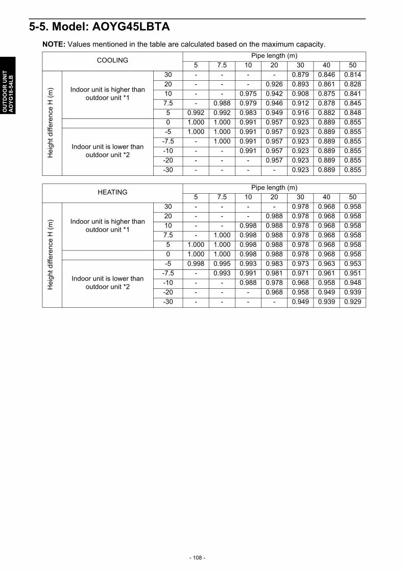
- 108 -
OU
TD
OO
R U
NIT
AO
YG
18-5
4LB
5-5. Model: AOYG45LBTA
NOTE: Values mentioned in the table are calculated based on the maximum capacity.
COOLINGPipe length (m)
5 7.5 10 20 30 40 50
He
igh
t di
ffer
ence
H (
m) Indoor unit is higher than
outdoor unit *1
30 - - - - 0.879 0.846 0.814
20 - - - 0.926 0.893 0.861 0.828
10 - - 0.975 0.942 0.908 0.875 0.841
7.5 - 0.988 0.979 0.946 0.912 0.878 0.845
5 0.992 0.992 0.983 0.949 0.916 0.882 0.848
0 1.000 1.000 0.991 0.957 0.923 0.889 0.855
Indoor unit is lower than outdoor unit *2
-5 1.000 1.000 0.991 0.957 0.923 0.889 0.855
-7.5 - 1.000 0.991 0.957 0.923 0.889 0.855
-10 - - 0.991 0.957 0.923 0.889 0.855
-20 - - - 0.957 0.923 0.889 0.855
-30 - - - - 0.923 0.889 0.855
HEATINGPipe length (m)
5 7.5 10 20 30 40 50
Hei
ght
diff
ere
nce
H (
m) Indoor unit is higher than
outdoor unit *1
30 - - - - 0.978 0.968 0.958
20 - - - 0.988 0.978 0.968 0.958
10 - - 0.998 0.988 0.978 0.968 0.958
7.5 - 1.000 0.998 0.988 0.978 0.968 0.958
5 1.000 1.000 0.998 0.988 0.978 0.968 0.958
0 1.000 1.000 0.998 0.988 0.978 0.968 0.958
Indoor unit is lower than outdoor unit *2
-5 0.998 0.995 0.993 0.983 0.973 0.963 0.953
-7.5 - 0.993 0.991 0.981 0.971 0.961 0.951
-10 - - 0.988 0.978 0.968 0.958 0.948
-20 - - - 0.968 0.958 0.949 0.939
-30 - - - - 0.949 0.939 0.929
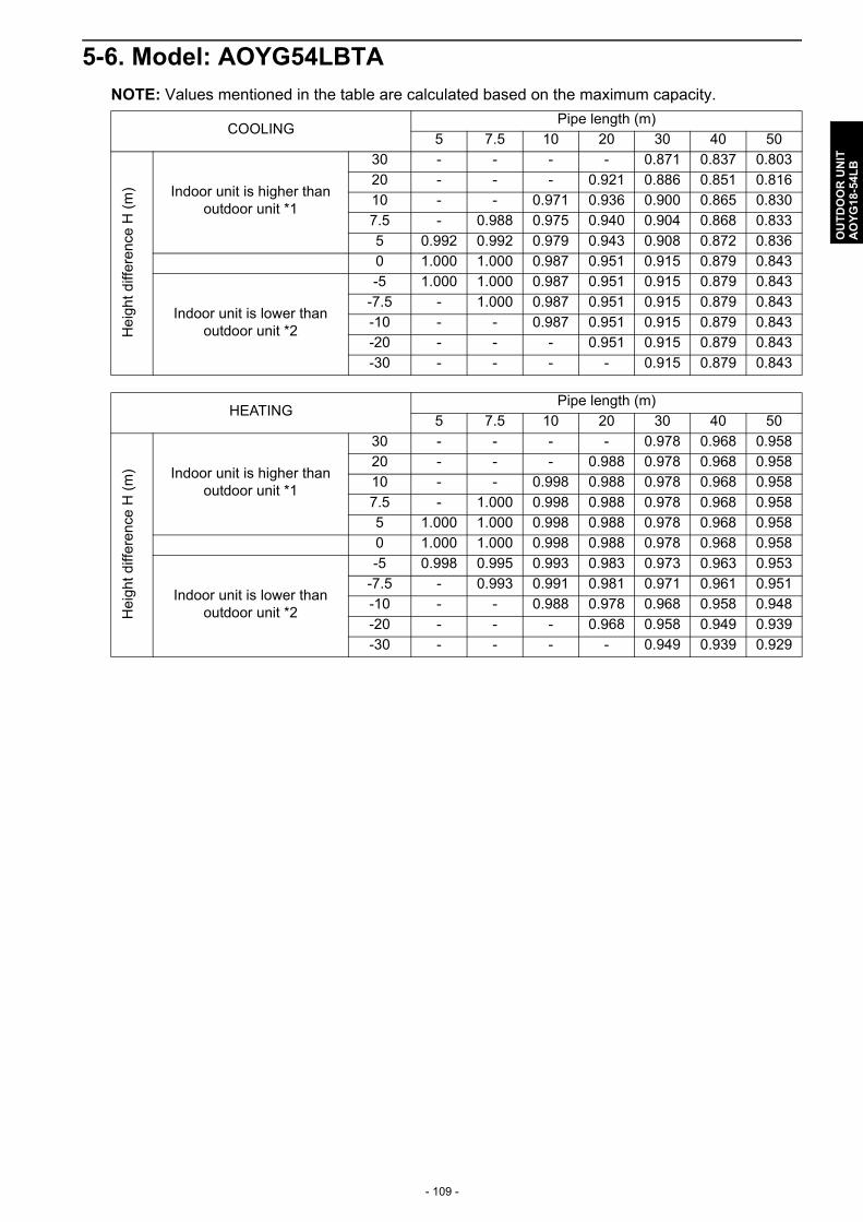
- 109 -
OU
TD
OO
R U
NIT
AO
YG
18-5
4LB
5-6. Model: AOYG54LBTA
NOTE: Values mentioned in the table are calculated based on the maximum capacity.
COOLINGPipe length (m)
5 7.5 10 20 30 40 50H
eig
ht
diff
eren
ce H
(m
) Indoor unit is higher than outdoor unit *1
30 - - - - 0.871 0.837 0.803
20 - - - 0.921 0.886 0.851 0.816
10 - - 0.971 0.936 0.900 0.865 0.830
7.5 - 0.988 0.975 0.940 0.904 0.868 0.833
5 0.992 0.992 0.979 0.943 0.908 0.872 0.836
0 1.000 1.000 0.987 0.951 0.915 0.879 0.843
Indoor unit is lower than outdoor unit *2
-5 1.000 1.000 0.987 0.951 0.915 0.879 0.843
-7.5 - 1.000 0.987 0.951 0.915 0.879 0.843
-10 - - 0.987 0.951 0.915 0.879 0.843
-20 - - - 0.951 0.915 0.879 0.843
-30 - - - - 0.915 0.879 0.843
HEATINGPipe length (m)
5 7.5 10 20 30 40 50
Hei
ght
diff
ere
nce
H (
m) Indoor unit is higher than
outdoor unit *1
30 - - - - 0.978 0.968 0.958
20 - - - 0.988 0.978 0.968 0.958
10 - - 0.998 0.988 0.978 0.968 0.958
7.5 - 1.000 0.998 0.988 0.978 0.968 0.958
5 1.000 1.000 0.998 0.988 0.978 0.968 0.958
0 1.000 1.000 0.998 0.988 0.978 0.968 0.958
Indoor unit is lower than outdoor unit *2
-5 0.998 0.995 0.993 0.983 0.973 0.963 0.953
-7.5 - 0.993 0.991 0.981 0.971 0.961 0.951
-10 - - 0.988 0.978 0.968 0.958 0.948
-20 - - - 0.968 0.958 0.949 0.939
-30 - - - - 0.949 0.939 0.929

- 110 -
OU
TD
OO
R U
NIT
AO
YG
18-5
4LB
6. Additional charge calculation
6-1. Models: AOYG18LBCA and AOYG24LBCA
Refrigerant charge
6-2. Models: AOYG30LBTA and AOYG36LBTA
Refrigerant charge
6-3. Models: AOYG45LBTA and AOYG54LBTA
Refrigerant charge
Refrigerant type R410A
Refrigerant amount g 1,800
Total pipe length m 15 or less 20 30 (Max.) 20 g/m
Additional charge g 0 100 300
Refrigerant type R410A
Refrigerant amount g 2,100
Total pipe length m 20 or less 30 40 50 (Max.) 40 g/m
Additional charge g 0 400 800 1,200
Refrigerant type R410A
Refrigerant amount g 3,350
Total pipe length m 20 or less 30 40 50 (Max.)40 g/m
Additional charge g 0 400 800 1,200
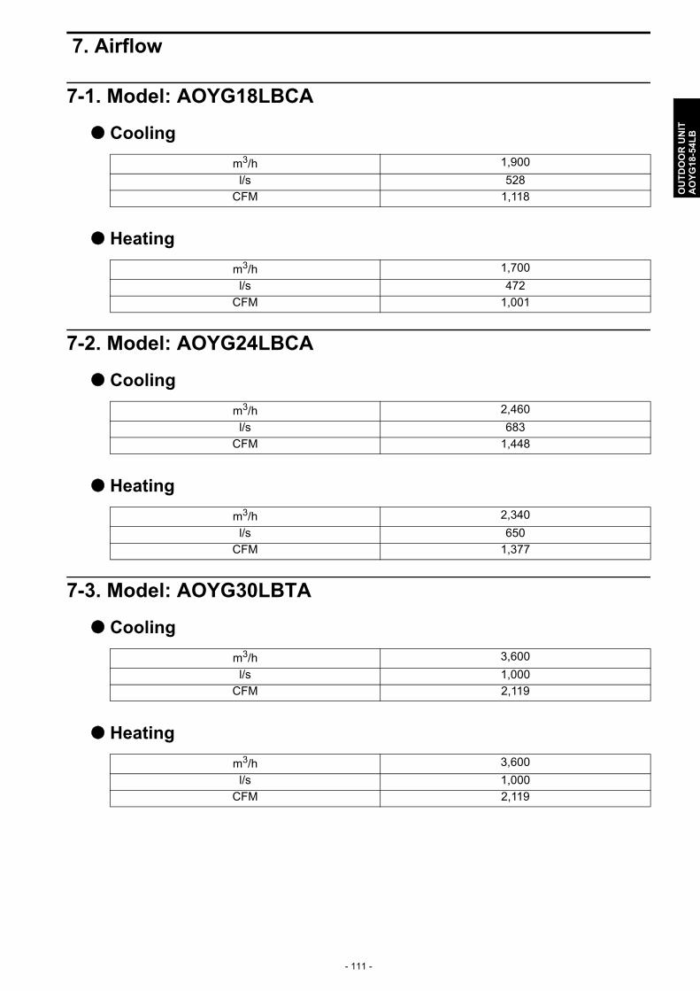
- 111 -
OU
TD
OO
R U
NIT
AO
YG
18-5
4LB
7. Airflow
7-1. Model: AOYG18LBCA
Cooling
Heating
7-2. Model: AOYG24LBCA
Cooling
Heating
7-3. Model: AOYG30LBTA
Cooling
Heating
m3/h 1,900
l/s 528
CFM 1,118
m3/h 1,700
l/s 472
CFM 1,001
m3/h 2,460
l/s 683
CFM 1,448
m3/h 2,340
l/s 650
CFM 1,377
m3/h 3,600
l/s 1,000
CFM 2,119
m3/h 3,600
l/s 1,000
CFM 2,119

- 112 -
OU
TD
OO
R U
NIT
AO
YG
18-5
4LB
7-4. Model: AOYG36LBTA
Cooling
Heating
7-5. Model: AOYG45LBTA
Cooling
Heating
7-6. Model: AOYG54LBTA
Cooling
Heating
m3/h 3,800
l/s 1,056
CFM 2,237
m3/h 3,800
l/s 1,056
CFM 2,237
m3/h 6,750
l/s 1,875
CFM 3,973
m3/h 6,200
l/s 1,722
CFM 3,649
m3/h 6,750
l/s 1,875
CFM 3,973
m3/h 6,850
l/s 1,903
CFM 4,032

- 113 -
OU
TD
OO
R U
NIT
AO
YG
18-5
4LB
8. Operation noise (sound pressure)
8-1. Noise level curve
Model: AOYG18LBCA
Cooling Heating
Model: AOYG24LBCA
Cooling Heating
0
10
20
30
40
50
60
70
80
63 125 250 500 1000 2000 4000 8000
Oct
ave
band
sou
nd p
ress
ure
leve
l, dB
:(0dB
=20μ
Pa)
Octave band center frequency ,Hz
NC-65
NC-60
NC-55
NC-50
NC-45
NC-40
NC-35
NC-30
NC-25
NC-20
NC-15
0
10
20
30
40
50
60
70
80
63 125 250 500 1000 2000 4000 8000
Oct
ave
band
sou
nd p
ress
ure
leve
l, dB
:(0dB
=20μ
Pa)
Octave band center frequency ,Hz
NC-65
NC-60
NC-55
NC-50
NC-45
NC-40
NC-35
NC-30
NC-25
NC-20
NC-15
0
10
20
30
40
50
60
70
80
63 125 250 500 1000 2000 4000 8000
Oct
ave
band
sou
nd p
ress
ure
leve
l, dB
:(0dB
=20μ
Pa)
Octave band center frequency ,Hz
NC-65
NC-60
NC-55
NC-50
NC-45
NC-40
NC-35
NC-30
NC-25
NC-20
NC-15
0
10
20
30
40
50
60
70
80
63 125 250 500 1000 2000 4000 8000
Oct
ave
band
sou
nd p
ress
ure
leve
l, dB
:(0dB
=20μ
Pa)
Octave band center frequency ,Hz
NC-65
NC-60
NC-55
NC-50
NC-45
NC-40
NC-35
NC-30
NC-25
NC-20
NC-15

- 114 -
OU
TD
OO
R U
NIT
AO
YG
18-5
4LB
Model: AOYG30LBTA
Cooling Heating
Model: AOYG36LBTA
Cooling Heating
0
10
20
30
40
50
60
70
80
63 125 250 500 1000 2000 4000 8000
Oct
ave
band
sou
nd p
ress
ure
leve
l, dB
:(0dB
=20μ
Pa)
Octave band center frequency ,Hz
NC-65
NC-60
NC-55
NC-50
NC-45
NC-40
NC-35
NC-30
NC-25
NC-20
NC-15
0
10
20
30
40
50
60
70
80
63 125 250 500 1000 2000 4000 8000
Oct
ave
band
sou
nd p
ress
ure
leve
l, dB
:(0dB
=20μ
Pa)
Octave band center frequency ,Hz
NC-65
NC-60
NC-55
NC-50
NC-45
NC-40
NC-35
NC-30
NC-25
NC-20
NC-15
0
10
20
30
40
50
60
70
80
63 125 250 500 1000 2000 4000 8000
Oct
ave
band
sou
nd p
ress
ure
leve
l, dB
:(0dB
=20μ
Pa)
Octave band center frequency ,Hz
NC-65
NC-60
NC-55
NC-50
NC-45
NC-40
NC-35
NC-30
NC-25
NC-20
NC-15
-
0
10
20
30
40
50
60
70
80
63 125 250 500 1000 2000 4000 8000
Oct
ave
band
sou
nd p
ress
ure
leve
l, dB
:(0dB
=20μ
Pa)
Octave band center frequency ,Hz
NC-65
NC-60
NC-55
NC-50
NC-45
NC-40
NC-35
NC-30
NC-25
NC-20
NC-15

- 115 -
OU
TD
OO
R U
NIT
AO
YG
18-5
4LB
Model: AOYG45LBTA
Cooling Heating
Model: AOYG54LBTA
Cooling Heating
0
10
20
30
40
50
60
70
80
63 125 250 500 1000 2000 4000 8000
Oct
ave
band
sou
nd p
ress
ure
leve
l, dB
:(0dB
=20μ
Pa)
Octave band center frequency ,Hz
NC-65
NC-60
NC-55
NC-50
NC-45
NC-40
NC-35
NC-30
NC-25
NC-20
NC-15
0
10
20
30
40
50
60
70
80
63 125 250 500 1000 2000 4000 8000O
ctav
e ba
nd s
ound
pre
ssur
e le
vel,
dB:(0
dB=2
0μP
a)Octave band center frequency ,Hz
NC-65
NC-60
NC-55
NC-50
NC-45
NC-40
NC-35
NC-30
NC-25
NC-20
NC-15
-
0
10
20
30
40
50
60
70
80
63 125 250 500 1000 2000 4000 8000
Oct
ave
band
sou
nd p
ress
ure
leve
l, dB
:(0dB
=20μ
Pa)
Octave band center frequency ,Hz
NC-65
NC-60
NC-55
NC-50
NC-45
NC-40
NC-35
NC-30
NC-25
NC-20
NC-15
-
0
10
20
30
40
50
60
70
80
63 125 250 500 1000 2000 4000 8000
Oct
ave
band
sou
nd p
ress
ure
leve
l, dB
:(0dB
=20μ
Pa)
Octave band center frequency ,Hz
NC-65
NC-60
NC-55
NC-50
NC-45
NC-40
NC-35
NC-30
NC-25
NC-20
NC-15

- 116 -
OU
TD
OO
R U
NIT
AO
YG
18-5
4LB
8-2. Sound level check point
NOTE: Detailed shape of the actual outdoor unit might be slightly different from the one illustrated above.
1 m
MicrophoneMicrophone
Rear
Airflow
Rear viewSide view
1 m
AirflowMicrophoneMicrophone
Rear
Rear viewSide view

- 117 -
OU
TD
OO
R U
NIT
AO
YG
18-5
4LB
9. Electrical characteristics
*1: The maximum current is the total current of indoor unit and outdoor unit.*2: Selected sample based on Japan Electrotechnical Standards and Codes Committee E0005. Asthe regulations of wire size and circuit breaker differ in each country or region, select appropriatedevices complied to the regional standard.*3: Limit voltage drop to less than 2%. Increase conductor size if voltage drop is 2% or more.
Model name AOYG18LBCA AOYG24LBCA
Power supply Voltage V 230
Frequency Hz 50
Max. operating current*1 A 13.5 18.5
Wiring spec. *2
Circuit breaker current A 25 30
Power cable mm2 4.0
Connection cable *3 mm2 1.5—2.5
Limited wiring length m 31
Model name AOYG30LBTA AOYG36LBTA AOYG45LBTA AOYG54LBTA
Power supply
Voltage V 230
Frequency Hz 50
Max. operating current*1 A 17.0 20.0 20.5 21.5
Wiring spec. *2
Circuit breaker current
A 30
Power cable mm2 4.0 6.0
Connection cable *3 mm2 1.5—2.5
Limited wiring length
m 51

- 118 -
OU
TD
OO
R U
NIT
AO
YG
18-5
4LB
10. Safety devices
Type of protection
Protection formModel
AOYG18LBCA AOYG24LBCA
Circuit protection
Current fuse (Filter PCB)
250 V, 20 A250 V, 5 A
Current fuse (Main PCB)
250 V, 3.15 A
Fan motor protection
Thermal protection program
Activate100±10°C
Fan motor stop
Reset95 ±10°C
Fan motor restart
Compressor protection
Terminal protection program (Compressor temp.)
Activate108°C
Compressor stop
Reset80°C
Compressor restart
Thermal protection program (Discharge temp.)
Activate110°C
Compressor stop
ResetAfter 7 minutes
Compressor restart
High pressure protection
Pressure switchActivate
4.2±0.1 MPaCompressor stop
Reset3.2±0.15 MPa
Compressor restart
Low pressure protection
Pressure sensorActivate
0.12 MPaCompressor stop
Reset0.15 MPa
Compressor restart
Type of protection
Protection formModel
AOYG30LBTA AOYG36LBTA
Circuit protection
Current fuse (Near the terminal)
250 V, 25 A
Current fuse (Filter PCB)
250 V, 10 A
Current fuse (Main PCB)
250 V, 3.15 A
Fan motor protection
Thermal protection program
Activate150±15°C
Fan motor stop
Reset120±15°C
Fan motor restart
Compressor protection
Terminal protection program (Compressor temp.)
Activate108°C
Compressor stop
Reset80°C
Compressor restart
Thermal protection program (Discharge temp.)
Activate110°C
Compressor stop
ResetAfter 7 minutes
Compressor restart
High pressure protection
Pressure switchActivate
4.2±0.1 MPaCompressor stop
Reset3.2±0.15 MPa
Compressor restart

- 119 -
OU
TD
OO
R U
NIT
AO
YG
18-5
4LB
Type of protection
Protection formModel
AOYG45LBTA AOYG54LBTA
Circuit protection
Current fuse (Filter PCB)
250 V, 30 A250 V, 10 A × 2250 V, 3.15 A
Current fuse (Main PCB)
250 V, 3.15 A
Fan motor protection
Thermal protection program
Activate112±9°C
Fan motor stop
Reset116 +10/-9°C
Fan motor restart
Compressor protection
Terminal protection program (Compressor temp.)
Activate108°C
Compressor stop
Reset80°C
Compressor restart
Thermal protection program (Discharge temp.)
Activate110°C
Compressor stop
ResetAfter 7 minutes
Compressor restart
High pressure protection
Pressure switchActivate
4.2±0.1 MPaCompressor stop
Reset3.2±0.15 MPa
Compressor restart
Low pressure protection
Pressure sensorActivate
0.12 MPaCompressor stop
Reset0.15 MPa
Compressor restart
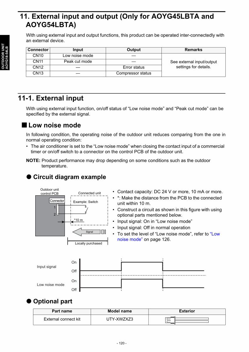
- 120 -
OU
TD
OO
R U
NIT
AO
YG
18-5
4LB
11. External input and output (Only for AOYG45LBTA and AOYG54LBTA)With using external input and output functions, this product can be operated inter-connectedly with an external device.
11-1. External inputWith using external input function, on/off status of “Low noise mode” and “Peak cut mode” can be specified by the external signal.
Low noise modeIn following condition, the operating noise of the outdoor unit reduces comparing from the one innormal operating condition:• The air conditioner is set to the “Low noise mode” when closing the contact input of a commercial
timer or on/off switch to a connector on the control PCB of the outdoor unit.
NOTE: Product performance may drop depending on some conditions such as the outdoor temperature.
Circuit diagram example
Optional part
Connector Input Output Remarks
CN10 Low noise mode —
See external input/output settings for details.
CN11 Peak cut mode —
CN12 — Error status
CN13 — Compressor status
• Contact capacity: DC 24 V or more, 10 mA or more.• *: Make the distance from the PCB to the connected
unit within 10 m.• Construct a circuit as shown in this figure with using
optional parts mentioned below.• Input signal: On in “Low noise mode”• Input signal: Off in normal operation• To set the level of “Low noise mode”, refer to “Low
noise mode” on page 126.
Part name Model name Exterior
External connect kit UTY-XWZXZ3
Outdoor unit control PCB Connected unit
Example: SwitchConnector
1
2
Signal
Locally purchased
*10 m
On
Off
On
Off
Input signal
Low noise mode

- 121 -
OU
TD
OO
R U
NIT
AO
YG
18-5
4LB
Peak cut modeBy performing following on-site work, operation that suppresses the current value can be enabled: • The air conditioner is set to the “Peak cut mode” when closing the contact input of a commercial
timer or on/off switch to a connector on the control PCB of the outdoor unit.
Circuit diagram example
Optional part
• Contact capacity: DC 24 V or more, 10 mA or more.• *: Make the distance from the PCB to the connected
unit within 10 m.• Construct a circuit as shown in this figure with using
optional parts mentioned below.• Input signal: On in “Peak cut mode”• Input signal: Off in normal operation• To set the level of “Peak cut mode”, refer to “Peak
cut mode” on page 127.
Part name Model name Exterior
External connect kit UTY-XWZXZ3
Outdoor unit control PCB Connected unit
Example: SwitchConnector
1
2
Signal
Locally purchased
*10 m
On
Off
On
Off
Input signal
Peak cut mode
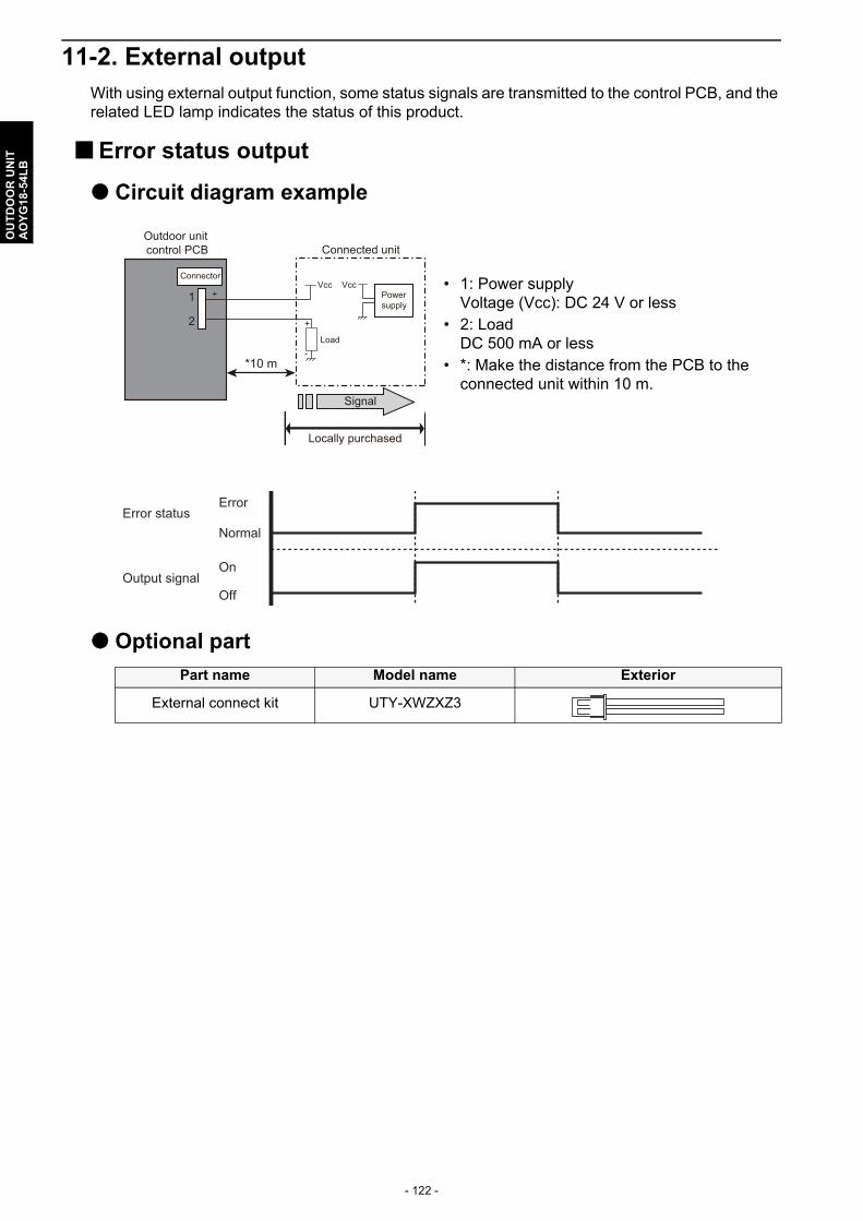
- 122 -
OU
TD
OO
R U
NIT
AO
YG
18-5
4LB
11-2. External outputWith using external output function, some status signals are transmitted to the control PCB, and the related LED lamp indicates the status of this product.
Error status output
Circuit diagram example
Optional part
• 1: Power supplyVoltage (Vcc): DC 24 V or less
• 2: LoadDC 500 mA or less
• *: Make the distance from the PCB to the connected unit within 10 m.
Part name Model name Exterior
External connect kit UTY-XWZXZ3
Signal
Outdoor unit control PCB Connected unit
Connector
1
2
Locally purchased
*10 m
Vcc+
+
-Load
VccPowersupply
Error
Normal
On
Off
Error status
Output signal
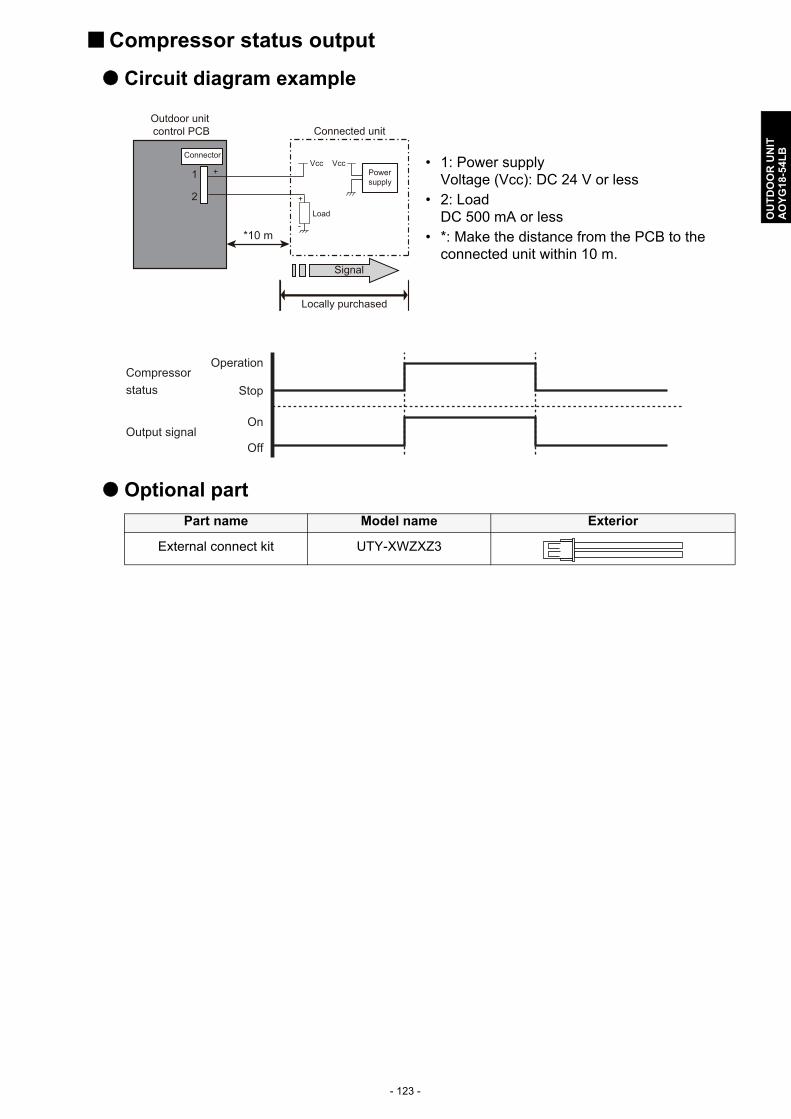
- 123 -
OU
TD
OO
R U
NIT
AO
YG
18-5
4LB
Compressor status output
Circuit diagram example
Optional part
• 1: Power supplyVoltage (Vcc): DC 24 V or less
• 2: LoadDC 500 mA or less
• *: Make the distance from the PCB to the connected unit within 10 m.
Part name Model name Exterior
External connect kit UTY-XWZXZ3
Signal
Outdoor unit control PCB Connected unit
Connector
1
2
Locally purchased
*10 m
Vcc+
+
-Load
VccPowersupply
Operation
Stop
On
Off
Compressor status
Output signal
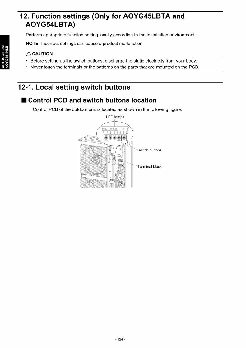
- 124 -
OU
TD
OO
R U
NIT
AO
YG
18-5
4LB
12. Function settings (Only for AOYG45LBTA and AOYG54LBTA)Perform appropriate function setting locally according to the installation environment.
NOTE: Incorrect settings can cause a product malfunction.
! CAUTION
• Before setting up the switch buttons, discharge the static electricity from your body.• Never touch the terminals or the patterns on the parts that are mounted on the PCB.
12-1. Local setting switch buttons
Control PCB and switch buttons locationControl PCB of the outdoor unit is located as shown in the following figure.
Terminal block
Switch buttons
LED lamps

- 125 -
OU
TD
OO
R U
NIT
AO
YG
18-5
4LB
Switch buttons and the functions
LED lamp Function or operation method
(1) POWER/MODE GreenLights on while power on.Local setting in outdoor unit or error code is displayed with blink.
(2) ERROR Red Blinks during error operation.
(3) PUMP DOWN (L1) Orange Lights on during pump down operation.
(4)LOW NOISE MODE (L2 and L3)
OrangeLights on during “Low noise mode” when local setting is activated.(Lighting pattern of L2 and L3 indicates low noise level.)
(5)PEAK CUT MODE(L4, L5, and L6)
OrangeLights on during “Peak cut mode” when local setting is activated.(Lighting pattern of L4, L5, and L6 indicates peak cut level.)
Switch button Function or operation method
SW1 MODE Switches between “Local setting” and “Error code display”.
SW2 SELECTSwitches between the individual “Local settings” and the “Error code displays”.
SW3 ENTERSwitches between the individual “Local settings” and the “Error code displays”.
SW4 EXIT Returns to “Operation status display”.
SW5 PUMP DOWN Starts the pump down operation.
SW1 SW2 SW3 SW4 SW5
(1) (2) (3) (4) (5)
LED lamps
Switch buttons

- 126 -
OU
TD
OO
R U
NIT
AO
YG
18-5
4LB
12-2. Local setting procedure
NOTE: Before performing the function setting, be sure to stop the operation of the air conditioner.
Low noise mode
1. Press the MODE switch button (SW1) for 3 seconds or more to switch to “Local setting mode”.
2. After confirming the LED lamp of POWER/MODE blinks 9 times, press the ENTER switch button (SW3).
3. Press the SELECT switch button (SW2), and adjust the LED lamp as shown below. Then the LED lamp indicates the current setting.
4. Press the ENTER switch button (SW3).
5. Press the SELECT switch button (SW2), and adjust the LED lamps as shown below.
SW1 SW2 SW3 SW4 SW5
(1) (2) (3) (4) (5)
LED lamps
Switch buttons
POWER
MODEERROR
(L1) (L2) (L3) (L4) (L5) (L6)
PUMPDOWN LOW NOISE PEAK CUT
Blinks(9 times)
Sign “ ”: Lights off
(L2) (L3)
LOW NOISE
BlinkLOW NOISEMODE
(L2) (L3)
LOW NOISE
LOW NOISEMOD E
Sign “ ”: Lights on
PEAK CUT
MODE 1
MODE 2 Blink
Blink
(L4) (L5) (L6)

- 127 -
OU
TD
OO
R U
NIT
AO
YG
18-5
4LB
6. Press the ENTER switch button (SW3) and fix it.
7. To return to “Operating status display (Normal operation)”, press the EXIT switch button (SW4).
In case of missing how many times you pressed the SELECT and ENTER switch buttons:1. To return to “Operation status display (Normal operation)”, press the EXIT switch button once.2. Restart from the beginning of setting procedure.
NOTE: In case of missing how many times you pressed the SELECT and ENTER switch buttons, you must redo the setting procedure. Return to “Operation status display (Normal opera-tion)” by pressing the EXIT switch button once, and restart from the beginning of the setting procedure.
Peak cut mode
1. Press the MODE switch button (SW1) for 3 seconds or more to switch to “Local setting mode”.
2. After confirming the LED lamp of POWER/MODE blinks 9 times, press the ENTER switch button (SW3).
3. Press the SELECT switch button (SW2), and adjust the LED lamp as shown below. Then the LED lamp indicates the current setting.
PEAK CUT
MODE 1
MODE 2
(L4) (L5) (L6)
SW1 SW2 SW3 SW4 SW5
(1) (2) (3) (4) (5)
LED lamps
Switch buttons
POWER
MODEERROR
(L1) (L2) (L3) (L4) (L5) (L6)
PUMPDOWN LOW NOISE PEAK CUT
Blinks(9 times)
Sign “ ”: Lights off
(L2) (L3)
LOW NOISE
BlinkPEAK CUTMOD E

- 128 -
OU
TD
OO
R U
NIT
AO
YG
18-5
4LB
4. Press the ENTER switch button (SW3).
5. Press the SELECT switch button (SW2), and adjust the LED lamps as shown below.
6. Press the ENTER switch button (SW3) and fix it.
7. To return to “Operating status display (Normal operation)”, press the EXIT switch button (SW4).
NOTE: When pressed number is lost during setting, you must redo the setting procedure. Return to “Operation status display (Normal operation)” by pressing the EXIT switch button once, and restart from the beginning of the setting procedure.
(L2) (L3)
LOW NOISE
PEAK CUTMODE
Sign “ ”: Lights on
100 % of rated input ratio
75 % of rated input ratio
50 % of rated input ratio
0 % of rated input ratio
Blink
Blink Blink
Blink
Blink
PEAK CUT
(L4) (L5) (L6)
100 % of rated input ratio
75 % of rated input ratio
50 % of rated input ratio0 % of rated input ratio
PEAK CUT
(L4) (L5) (L6)

- 129 -
OU
TD
OO
R U
NIT
AO
YG
18-5
4LB
13. Optional parts
Exterior Part name Model name Summary
External connect kit
UTY-XWZXZ3Use to operate the external input and output functions of outdoor unit. (For 45 and 54 models)