Embed Size (px)
Citation preview
Hebel® PowerBlock™ Design and Installation Guide
Design & Installation Guide
Hebel® PowerBlock™ Design and Installation Guide 2
It is the responsibility of the architectural designer and engineering parties to ensure that the details in the Hebel®® PowerBlock™ Design and Installation Guide are appropriate for the intended application. The recommendations of this guide are formulated along the lines of good building practice, but are not intended to be an exhaustive statement of all relevant data. Hebel®® accepts no responsibility for or in connection with the quality of the recommendations or their suitability for any purpose when installed.
Contents
1.0 Introduction 3
2.0 Benefits 4
3.0 Energy Efficiency 5
4.0 Fire 5
5.0 Acoustic 5
6.0 Design Approach 6
7.0 Structure 8
7.1 Slabs and Strip Footings 8
7.2 Hebel PowerBlock™ Walls 11
7.3 Floor Panel Systems 14
7.4 Decks, Verandahs and Pergolas 17
8.0 System Components 18
9.0 Construction Notes 19
10.0 Tools & Equipment for Construction 23
11.0 Fixings for use with Hebel 24
12.0 PowerBlock™ Handling 25
13.0 Delivery & Storage 25
14.0 Construction Details (Typical) 26
Base of Wall 26
Top of Wall 29
Wall Junctions 31
Control Joints 32
Floors 35
Balcony and Deck 37
Stairs 39
Openings 40
15.0 Construction Details (Tie-down) 43
Appendix A: Carpet Installation 51
Hebel® PowerBlock™ Design and Installation Guide3
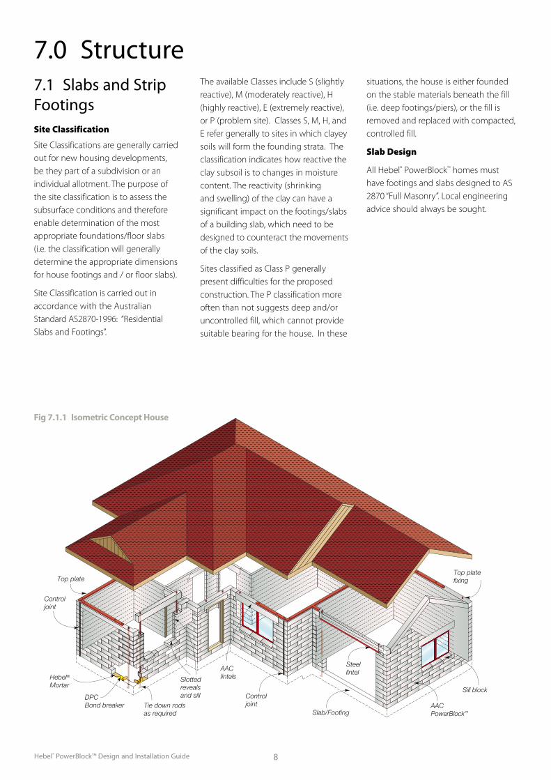
AACPowerBlock™
AAClintels
Sill block
Slab/Footing
Controljoint
Controljoint
Top plateTop platefixing
DPCBond breaker
Hebel® Mortar
Tie down rodsas required
Slottedreveals and sill
Steellintel
CSR Panel Systems is a division
of CSR Building Products Limited,
one of Australia’s leading building
products companies.
CSR Panel Systems manufactures
Hebel® Autoclaved Aerated Concrete
(AAC). The AAC in Hebel® products
is manufactured from sand, lime and
cement to which a gas-forming agent
is added. The liberated gas expands
the mixture, forming extremely small,
finely dispersed air pockets, resulting in
lightweight aerated concrete.
CSR Panel Systems has manufactured
Hebel® products that have won
wide acceptance as innovative
and environmentally preferable
building materials. This is due to their
lightweight nature, excellent thermal,
fire and acoustic properties and design
versatility. These inherent properties
of Hebel® products help achieve quick
and cost efficient construction practices
as well as providing for comfortable
operating environments inside the
buildings all year round.
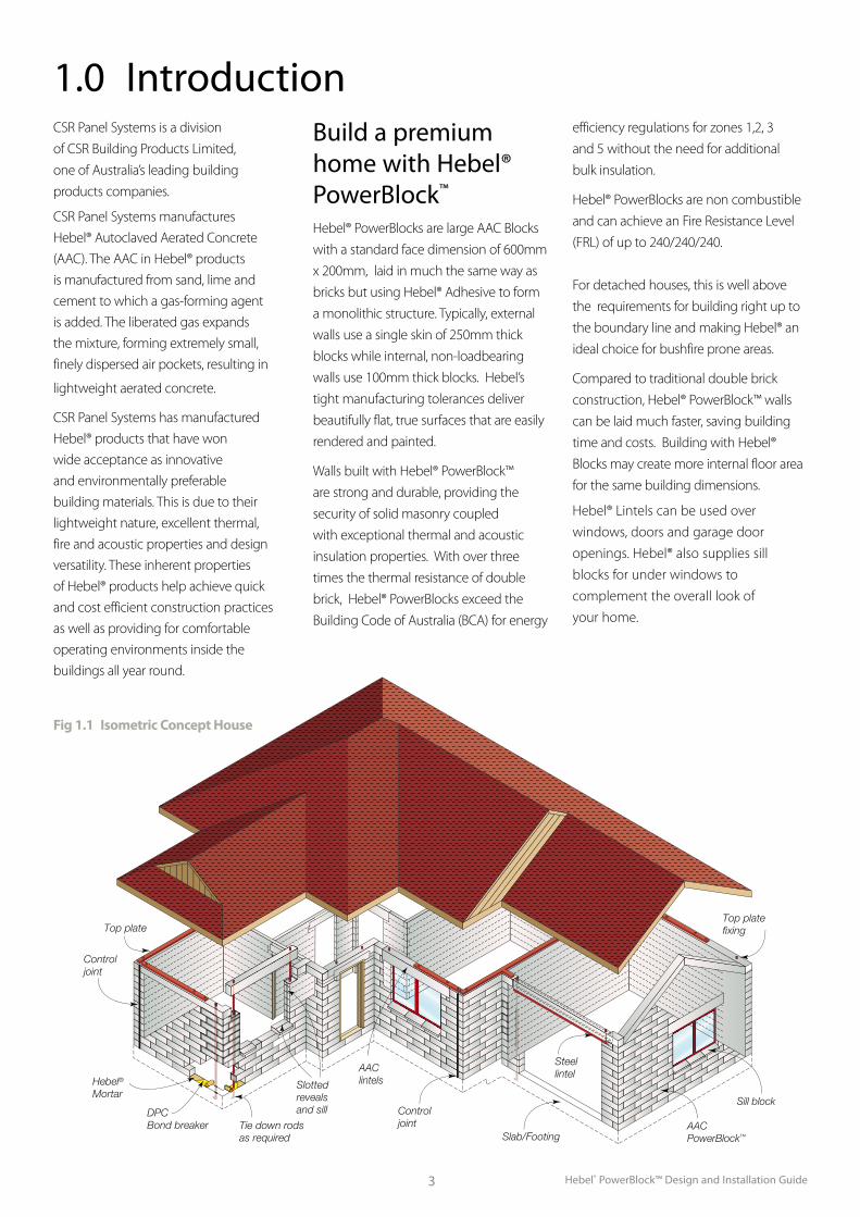
Build a premium home with Hebel® PowerBlock™
Hebel® PowerBlocks are large AAC Blocks
with a standard face dimension of 600mm
x 200mm, laid in much the same way as
bricks but using Hebel® Adhesive to form
a monolithic structure. Typically, external
walls use a single skin of 250mm thick
blocks while internal, non-loadbearing
walls use 100mm thick blocks. Hebel’s
tight manufacturing tolerances deliver
beautifully flat, true surfaces that are easily
rendered and painted.
Walls built with Hebel® PowerBlock™
are strong and durable, providing the
security of solid masonry coupled
with exceptional thermal and acoustic
insulation properties. With over three
times the thermal resistance of double
brick, Hebel® PowerBlocks exceed the
Building Code of Australia (BCA) for energy
efficiency regulations for zones 1,2, 3
and 5 without the need for additional
bulk insulation.
Hebel® PowerBlocks are non combustible
and can achieve an Fire Resistance Level
(FRL) of up to 240/240/240.
For detached houses, this is well above
the requirements for building right up to
the boundary line and making Hebel® an
ideal choice for bushfire prone areas.
Compared to traditional double brick
construction, Hebel® PowerBlock™ walls
can be laid much faster, saving building
time and costs. Building with Hebel®
Blocks may create more internal floor area
for the same building dimensions.
Hebel® Lintels can be used over
windows, doors and garage door
openings. Hebel® also supplies sill
blocks for under windows to
complement the overall look of
your home.
1.0 Introduction
Fig 1.1 Isometric Concept House
4
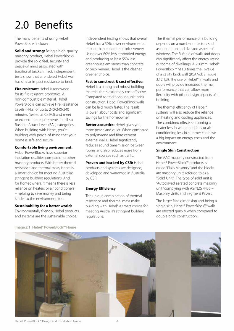
2.0 BenefitsThe many benefits of using Hebel PowerBlocks include:
Solid and strong: Being a high-quality masonry product, Hebel PowerBlocks provide the solid feel, security and peace-of mind associated with traditional bricks. In fact, independent tests show that a rendered Hebel wall has similar impact resistance to brick.
Fire resistant: Hebel is renowned for its fire resistant properties. A non-combustible material, Hebel PowerBlocks can achieve Fire Resistance Levels (FRLs) of up to 240/240/240 minutes (tested at CSIRO) and meet or exceed the requirements for all six Bushfire Attack Level (BAL) categories. When building with Hebel, you’re building with peace-of-mind that your home is safe and secure.
Comfortable living environment: Hebel PowerBlocks have superior insulation qualities compared to other masonry products. With better thermal resistance and thermal mass, Hebel is a smart choice for meeting Australia’s stringent building regulations. And, for homeowners, it means there is less reliance on heaters or air conditioners – helping to save money and being kinder to the environment, too.
Sustainability for a better world: Environmentally friendly, Hebel products and systems are the sustainable choice.
Independent testing shows that overall Hebel has a 30% lower environmental impact than concrete or brick veneer. Using over 60% less embodied energy, and producing at least 55% less greenhouse emissions than concrete or brick veneer, Hebel is the cleaner, greener choice.
Fast to construct & cost effective: Hebel is a strong and robust building material that’s extremely cost effective. Compared to traditional double brick construction, Hebel PowerBlock walls can be laid much faster. The result is lower labour costs and significant savings for the homeowner.
Better acoustics: Hebel gives you more peace and quiet. When compared to polystyrene and fibre cement external walls, Hebel significantly reduces sound transmission between rooms and also reduces noise from external sources such as traffic.
Proven and backed by CSR: Hebel products and systems are designed, developed and warranted in Australia by CSR.
Energy Efficiency
The unique combination of thermal resistance and thermal mass make building with Hebel® a smart choice for meeting Australia’s stringent building regulations.
The thermal performance of a building depends on a number of factors such as orientation and size and aspect of windows. The R-Value of walls and doors can significantly affect the energy-rating outcome of dwellings. A 250mm Hebel® PowerBlock™ has 3 times the R-Value of a cavity brick wall (BCA Vol. 2 Figure 3.12.1.3). The use of Hebel® in walls and doors will provide increased thermal performance that can allow more flexibility with other design aspects of a building.
The thermal efficiency of Hebel® systems will also reduce the reliance on heating and cooling appliances. The combined effects of running a heater less in winter and fans or air conditioning less in summer can have a big impact on energy costs and the environment.
Single Skin Construction
The AAC masonry constructed from Hebel® PowerBlock™ products is called “Plain Masonry” and the blocks are masonry units referred to as a “Solid Unit”. The type of solid unit is “Autoclaved aerated concrete masonry unit” complying with AS/NZS 4455 – Masonry Units and Segment Pavers
The larger face dimension and being a single skin, Hebel® PowerBlock™ walls are erected quickly when compared to double brick construction.
Image.2.1 Hebel® PowerBlock™ Home
Hebel® PowerBlock™ Design and Installation Guide
Hebel® PowerBlock™ Design and Installation Guide5
Table 3.1 identifies the minimum deemed to satisfy the R-Value requirements in accordance with BCA for Climate Zones
1 to 8. Table 3.2 lists the R-Values for various Hebel blockwall systems. For more information on Hebel® and energy
efficiency refer to Section 3 and Appendix C and D of the Hebel® Technical Manual.
3.0 Energy Efficiency
Table 3.1: Low-Rise Multi Residential Buildings
Table 3.2: Wall Element R-Value
Table 5.1: Acoustic Performance
PowerBlock™ Thickness Rw Rw + Ctr
100 38 35
150 43 40
250 45 42
Values for PowerBlock™ only, no linings.
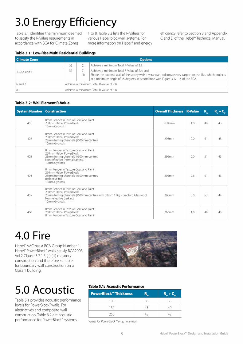
4.0 FireHebel® AAC has a BCA Group Number 1. Hebel® PowerBlock™ walls satisfy BCA2008 Vol.2 Clause 3.7.1.5 (a) (iii) masonry construction and therefore suitable for boundary wall construction on a Class 1 building.
5.0 AcousticTable 5.1 provides acoustic performance levels for PowerBlock™ walls. For alternatives and composite wall construction, Table 3.2 are acoustic performance for PowerBlock™ systems.
System Number Construction Overall Thickness R-Value Rw Rw + Ctr
4018mm Render in Texture Coat and Paint250mm Hebel PowerBlock10mm Gyprock
268 mm 1.8 48 43
402
8mm Render in Texture Coat and Paint250mm Hebel PowerBlock28mm furring channels @600mm centres10mm Gyprock
296mm 2.0 51 43
403
8mm Render in Texture Coat and Paint250mm Hebel PowerBlock28mm furring channels @600mm centresNon reflective (normal sarking)10mm Gyprock
296mm 2.0 51 43
404
8mm Render in Texture Coat and Paint250mm Hebel PowerBlock28mm furring channels @600mm centresReflective foil10mm Gyprock
296mm 2.6 51 43
405
8mm Render in Texture Coat and Paint250mm Hebel PowerBlock28mm furring channels @600mm centres with 50mm 11kg - Bradford GlasswoolNon reflective (sarking)10mm Gyprock
296mm 3.0 53 44
4068mm Render in Texture Coat and Paint250mm Hebel PowerBlock8mm Render in Texture Coat and Paint
216mm 1.8 48 43
Climate Zone Options
1,2,3,4 and 5
(a) (i) Achieve a minimum Total R-Value of 2.8.
(b) (i)(ii)
Achieve a minimum Total R-Value of 2.4; andShade the external wall of the storey with a verandah, balcony, eaves, carport or the like, which projects at a minimum angle of 15 degrees in accordance with Figure 3.12.1.2. of the BCA.
6 and 7 Achieve a minimum Total R-Value of 2.8.
8 Achieve a minimum Total R-Value of 3.8.
Hebel® PowerBlock™ Design and Installation Guide 6
6.0 Design Approach
There are 2 methods of construction – typical and tie-down. Typical is the most common method of building whilst the tie-down method is required for cyclonic or high wind areas (as determined by an engineer). This guide provides information for both building methods.
Important Note
It is the responsibility of the architectural designer and engineering parties to ensure that the information in the Hebel® PowerBlocks Design and Installation Guide is appropriate for the intended application. The recommendations of this guide are formulated along the lines of good building practice, but are not intended to be an exhaustive statement of all relevant data. Hebel® accepts no responsibility for or in connection with the quality of the recommendations or their suitability for any purpose when installed.
Scope
The Hebel® PowerBlocks Design and Installation Guide has been created to provide information for detached residential buildings. The design information in this guide has been condensed from the Hebel® Technical Manual and AS3700 Masonry structures. The design basis is AS3700 Masonry structures, Section 12 Simplified design of masonry for small buildings. The footing and slab design is based on AS2870 Residential slabs and footings – Construction.
Refer to Table 6.1 for Building Geometry Limitations.
Design Parameters
The structural design information in this guide is based on the data and assumptions in Table 6.2, 6.3 and 6.4.
Design Sequence
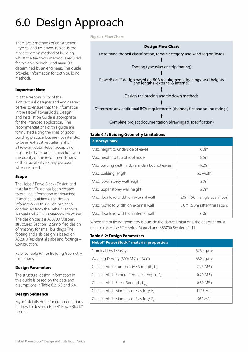
Fig. 6.1 details Hebel® recommendations for how to design a Hebel® PowerBlock™ home.
Design Flow Chart
Determine the soil classification, terrain category and wind region/loads
Footing type (slab or strip footing)
PowerBlock™ design based on BCA requirements, loadings, wall heights and lengths (external & internal)
Design the bracing and tie down methods
Determine any additional BCA requirements (thermal, fire and sound ratings)
Complete project documentation (drawings & specification)
Fig 6.1: Flow Chart
Table 6.1: Buiding Geometry Limitations
2 storeys max
Max. height to underside of eaves 6.0m
Max. height to top of roof ridge 8.5m
Max. building width incl. verandah but not eaves 16.0m
Max. building length 5x width
Max. lower storey wall height 3.0m
Max. upper storey wall height 2.7m
Max. floor load width on external wall 3.0m (6.0m single span floor)
Max. roof load width on external wall 3.0m (6.0m rafter/truss span)
Max. floor load width on internal wall 6.0m
Where the building geometry is outside the above limitations, the designer must refer to the Hebel® Technical Manual and AS3700 Sections 1-11.
Table 6.2: Design Parameters
Hebel® PowerBlock™ material properties:
Nominal Dry Density 525 kg/m2
Working Density (30% M.C of ACC) 682 kg/m2
Characteristic Compressive Strength, f ’m
2.25 MPa
Characteristic Flexural Tensile Strength, f ’mt
0.20 MPa
Characteristic Shear Strength, f ’ms
0.30 MPa
Characteristic Modulus of Elasticity, EST
1125 MPa
Characteristic Modulus of Elasticity, ELT
562 MPa
Hebel® PowerBlock™ Design and Installation Guide7
Image 6.1: Hebel® PowerBlock™ home Image 6.2: Hebel® PowerBlock™ home
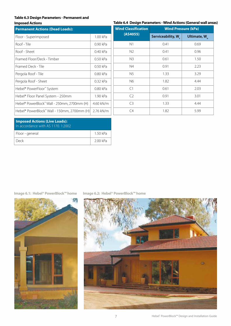
Table 6.3 Design Parameters - Permanent and Imposed Actions
Permanent Actions (Dead Loads):
Floor - Superimposed 1.00 kPa
Roof - Tile 0.90 kPa
Roof - Sheet 0.40 kPa
Framed Floor/Deck - Timber 0.50 kPa
Framed Deck - Tile 0.50 kPa
Pergola Roof - Tile 0.80 kPa
Pergola Roof - Sheet 0.32 kPa
Hebel® PowerFloor™ System 0.80 kPa
Hebel® Floor Panel System - 250mm 1.90 kPa
Hebel® PowerBlock™ Wall - 250mm, 2700mm (H) 4.60 kN/m
Hebel® PowerBlock™ Wall - 150mm, 2700mm (H) 2.76 kN/m
Table 6.4 Design Parameters - Wind Actions (General wall areas)
Wind Classification (AS4055)
Wind Pressure (kPa)
Serviceability, Ws Ultimate, Wu
N1 0.41 0.69
N2 0.41 0.96
N3 0.61 1.50
N4 0.91 2.23
N5 1.33 3.29
N6 1.82 4.44
C1 0.61 2.03
C2 0.91 3.01
C3 1.33 4.44
C4 1.82 5.99
Imposed Actions (Live Loads):In accordance with AS 1170. 1:2002
Floor - general 1.50 kPa
Deck 2.00 kPa
Hebel® PowerBlock™ Design and Installation Guide 8
7.1 Slabs and Strip FootingsSite Classification
Site Classifications are generally carried out for new housing developments, be they part of a subdivision or an individual allotment. The purpose of the site classification is to assess the subsurface conditions and therefore enable determination of the most appropriate foundations/floor slabs (i.e. the classification will generally determine the appropriate dimensions for house footings and / or floor slabs).
Site Classification is carried out in accordance with the Australian Standard AS2870-1996: “Residential Slabs and Footings”.
The available Classes include S (slightly reactive), M (moderately reactive), H (highly reactive), E (extremely reactive), or P (problem site). Classes S, M, H, and E refer generally to sites in which clayey soils will form the founding strata. The classification indicates how reactive the clay subsoil is to changes in moisture content. The reactivity (shrinking and swelling) of the clay can have a significant impact on the footings/slabs of a building slab, which need to be designed to counteract the movements of the clay soils.
Sites classified as Class P generally present difficulties for the proposed construction. The P classification more often than not suggests deep and/or uncontrolled fill, which cannot provide suitable bearing for the house. In these
situations, the house is either founded on the stable materials beneath the fill (i.e. deep footings/piers), or the fill is removed and replaced with compacted, controlled fill.
Slab Design
All Hebel® PowerBlock™ homes must have footings and slabs designed to AS 2870 “Full Masonry”. Local engineering advice should always be sought.
7.0 Structure
AACPowerBlock™
AAClintels
Sill block
Slab/Footing
Controljoint
Controljoint
Top plateTop platefixing
DPCBond breaker
Hebel® Mortar
Tie down rodsas required
Slottedreveals and sill
Steellintel
Fig 7.1.1 Isometric Concept House
Hebel® PowerBlock™ Design and Installation Guide9
d
s
b
SLAB MESH REFER TO SCHEDULE
EDGE BEAM
HEBEL MASONRY WALL
100
>50
REINFORCEMENT REFER TO SCHEDULE
d
b >50
REINFORCEMENT REFER TO SCHEDULE
>50
INTERNAL LOAD BEARING WALL
1-N12
N12-400, Z-BAR300 GOG
2-N12
R6-400 TIES
DPC SLIP JOINT
HEBEL MORTARDPC SLIP JOINT
HEBEL MORTAR
Hebel® Masonry Wall
Internal loadbearing wall
Slab mesh refer to scheduleDPC & Hebel®
Mortar
DPC & Hebel® Mortar
1- N12
b b>50 >50 >50
d
100 d
s2- N12
N12-400, Z-Bar 300 COG
R6-400 Ties
Edge Beam
Reinforcement refer to schedule
Reinforcement refer to schedule
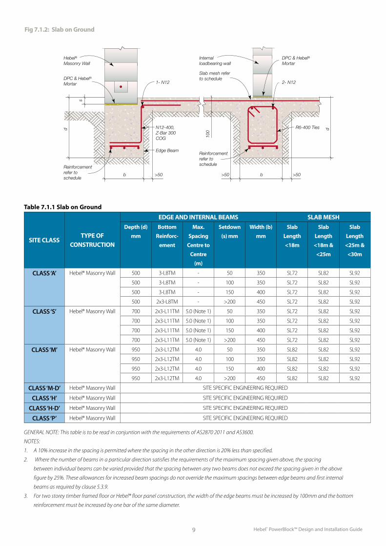
Table 7.1.1 Slab on Ground
SITE CLASSTYPE OF
CONSTRUCTION
EDGE AND INTERNAL BEAMS SLAB MESH
Depth (d)
mm
Bottom
Reinforc-
ement
Max.
Spacing
Centre to
Centre
(m)
Setdown
(s) mm
Width (b)
mm
Slab
Length
<18m
Slab
Length
<18m &
<25m
Slab
Length
<25m &
<30m
CLASS ‘A’ Hebel® Masonry Wall 500 3-L8TM - 50 350 SL72 SL82 SL92
500 3-L8TM - 100 350 SL72 SL82 SL92
500 3-L8TM - 150 400 SL72 SL82 SL92
500 2x3-L8TM - >200 450 SL72 SL82 SL92
CLASS ‘S’ Hebel® Masonry Wall 700 2x3-L11TM 5.0 (Note 1) 50 350 SL72 SL82 SL92
700 2x3-L11TM 5.0 (Note 1) 100 350 SL72 SL82 SL92
700 2x3-L11TM 5.0 (Note 1) 150 400 SL72 SL82 SL92
700 2x3-L11TM 5.0 (Note 1) >200 450 SL72 SL82 SL92
CLASS ‘M’ Hebel® Masonry Wall 950 2x3-L12TM 4.0 50 350 SL82 SL82 SL92
950 2x3-L12TM 4.0 100 350 SL82 SL82 SL92
950 2x3-L12TM 4.0 150 400 SL82 SL82 SL92
950 2x3-L12TM 4.0 >200 450 SL82 SL82 SL92
CLASS ‘M-D’ Hebel® Masonry Wall SITE SPECIFIC ENGINEERING REQUIRED
CLASS ‘H’ Hebel® Masonry Wall SITE SPECIFIC ENGINEERING REQUIRED
CLASS ‘H-D’ Hebel® Masonry Wall SITE SPECIFIC ENGINEERING REQUIRED
CLASS ‘P’ Hebel® Masonry Wall SITE SPECIFIC ENGINEERING REQUIRED
GENERAL NOTE: This table is to be read in conjuntion with the requirements of AS2870 2011 and AS3600.
NOTES:
1. A 10% increase in the spacing is permitted where the spacing in the other direction is 20% less than specified.
2. Where the number of beams in a particular direction satisfies the requirements of the maximum spacing given above, the spacing
between individual beams can be varied provided that the spacing between any two beams does not exceed the spacing given in the above
figure by 25%. These allowances for increased beam spacings do not override the maximum spacings between edge beams and first internal
beams as required by clause 5.3.9.
3. For two storey timber framed floor or Hebel® floor panel construction, the width of the edge beams must be increased by 100mm and the bottom
reinforcement must be increased by one bar of the same diameter.
Fig 7.1.2: Slab on Ground
Hebel® PowerBlock™ Design and Installation Guide 10
Sub-Floors On Elevated Sites
Hebel® PowerBlock™ must not be used at or below ground level. When building a Hebel® PowerBlock™ structure on a sloping site that is not suitable for a concrete slab, a solid core-filled concrete block or brick substructure may be erected on a strip footing to raise the building and floor system to a level that is clear of the ground resulting in a level building platform that allows sufficient airflow under the floor.
The first course of Hebel® PowerBlocks must be laid on a DPC to stop rising damp and to act as a bond breaker between the different building elements.
Termite Protection
Hebel® PowerBlocks are not a food source for termites. Solid wall construction still requires termite protection. There are many methods to protect your home against a termite invasion and a qualified professional pest control should be consulted to
determine the most suitable method for your design.
The Building Code of Australia recognises an exposed slab edge to a depth of 75mm above finished ground level as adequate termite prevention.
For masonry sub-floor construction a continuous ant cap installed between the brick/ concrete block work and the Hebel® PowerBlock™ also satisfies the Building Code of Australia termite protection requirements.
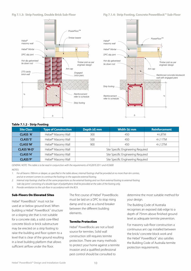
Table 7.1.2 - Strip Footing
Site Class Type of Construction Depth (d) mm Width (b) mm Reinforcement
CLASS ‘A’ Hebel® Masonry Wall 300 450 4-L8TM
CLASS ‘S’ Hebel® Masonry Wall 500 450 4-L11TM
CLASS ‘M’ Hebel® Masonry Wall 900 450 4-L12TM
CLASS ‘M-D’ Hebel® Masonry Wall Site Specific Engineering Required
CLASS ‘H’ Hebel® Masonry Wall Site Specific Engineering Required
CLASS ‘P’ Hebel® Masonry Wall Site Specific Engineering Required
GENERAL NOTE: This table is to be read in conjunction with the requirements of AS2870 2011 and AS3600
NOTES: 1. For all beams 700mm or deeper, as specified in the table above, internal footings shall be provided at no more than 6m centres, and at re-entrant corners to continue the footings to the opposite external footing. 2. Internal strip footings shall be of the same proportions as the external footing and run from external footing to external footing ‘side slip joints’ consisting of a double layer of polyethylene shall be provided at the sides of the footing only. 3. Provide ventilation to the sub-floor in accordance with the BCA.
Fig 7.1.3: Strip Footing, Double Brick Sub-Floor Fig 7.1.4: Strip Footing, Concrete PowerBlock™ Sub-Floor
270 CAVITY BRICK WALL
110 BRICK WALL WITH 230x230 ENGAGED BRICK PIERSSTRIP
FOOTING
ANT CAP
TIMBER JOIST AS PER ENGINEER DESIGN
TIMBER BEARER
POWER FLOOR
HEBEL MASONRY
WALL
SCALE = 1:20DOUBLE BRICK SUB-FLOOR
HOT DIP GALVANISED TIE
DOWN ROD
CORE-FILLED CONCRETE BLOCKWORK WALL WITH ENGAGED PIERS
STRIP FOOTING
HEBEL MASONRY
WALL
SCALE = 1:20CONCRETE BLOCK SUB-FLOOR
HOT DIP GALVANISED TIE
DOWN ROD
DPC SLIP JOINTDPC SLIP
JOINT
TIMBER JOIST AS PER ENGINEER DESIGNPOWER FLOOR
d
b
d
b
REINFORCEMENT REFER TO SCHEDULE
REINFORCEMENT REFER TO SCHEDULE
ANT CAP
HEBEL MORTARHEBEL
MORTAR
HOT DIP GALVANISED TIE
DOWN ROD
Powerfloor™ Joist
Ant cap + DPC
Brick engaged pier
Tie down rod
Strip footing to engineer’s details
Double brick
DPC Slip joint
Hebel® Blocks
PowerFloor™Hebel®
masonry wall
Hebel® Mortar
DPC slip joint
Hot dip galvanised
tie down rod
Reinforcement refer to schedule
Reinforced concrete blockwork wall with engaged piers
Ant cap
b
d
Strip footing
Timber joist as perengineer design
PowerFloor™
Timber bearerHebel®
masonry wall
Hebel® Mortar
DPC slip joint
Hot dip galvanised tie down rod
270 cavity brick wall
Reinforcement refer to schedule
Engaged brick piers
Ant cap
Strip footing
Timber joist as perengineer design
b
d
Hebel® PowerBlock™ Design and Installation Guide11
7.2 Hebel® PowerBlock™ Walls
Generally, the minimum recommended wall thickness is:
n 250mm for external walls
n 150mm for internal load-bearing walls.
n 100mm for internal non-load bearing walls.
Hebel® suggests considering a wall as having top and bottom lateral restraints only (one-way vertical span) and designing the appropriate wall thickness, so that retrofitting or changing the location of the movement joints will not be detrimental to the lateral load capacity of the wall. In determining the appropriate wall thickness, the designer shall consider a range of factors relating to relevant codes and project specific considerations, these factors may include:
n Movement joint location
n Bracing considerations
n Vertical (compression) loading
n Out of plane wind/earthquake (lateral) loading
n Required fire rating level (FRL).
The particular project loading configurations could result in walls that exceed the above minimum requirements.
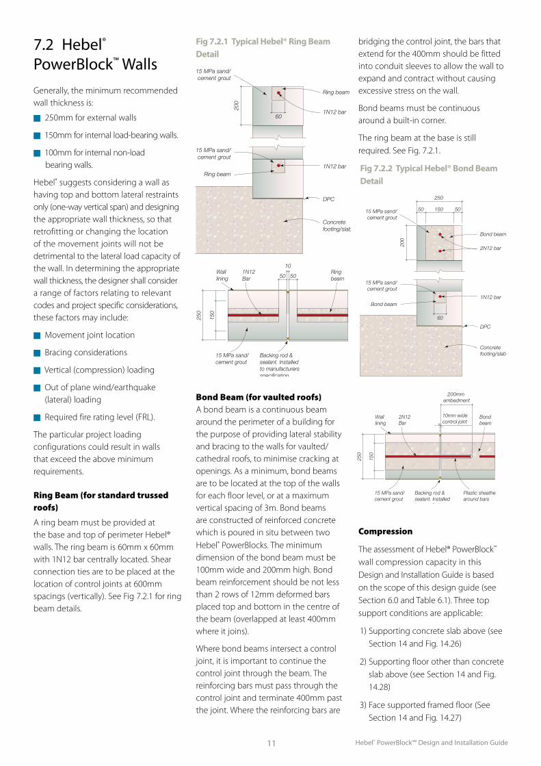
Ring Beam (for standard trussed roofs)
A ring beam must be provided at the base and top of perimeter Hebel® walls. The ring beam is 60mm x 60mm with 1N12 bar centrally located. Shear connection ties are to be placed at the location of control joints at 600mm spacings (vertically). See Fig 7.2.1 for ring beam details.
Bond Beam (for vaulted roofs)A bond beam is a continuous beam around the perimeter of a building for the purpose of providing lateral stability and bracing to the walls for vaulted/cathedral roofs, to minimise cracking at openings. As a minimum, bond beams are to be located at the top of the walls for each floor level, or at a maximum vertical spacing of 3m. Bond beams are constructed of reinforced concrete which is poured in situ between two Hebel® PowerBlocks. The minimum dimension of the bond beam must be 100mm wide and 200mm high. Bond beam reinforcement should be not less than 2 rows of 12mm deformed bars placed top and bottom in the centre of the beam (overlapped at least 400mm where it joins).
Where bond beams intersect a control joint, it is important to continue the control joint through the beam. The reinforcing bars must pass through the control joint and terminate 400mm past the joint. Where the reinforcing bars are
bridging the control joint, the bars that extend for the 400mm should be fitted into conduit sleeves to allow the wall to expand and contract without causing excessive stress on the wall.
Bond beams must be continuous around a built-in corner.
The ring beam at the base is still required. See Fig. 7.2.1.
Compression
The assessment of Hebel® PowerBlock™ wall compression capacity in this Design and Installation Guide is based on the scope of this design guide (see Section 6.0 and Table 6.1). Three top support conditions are applicable:
1) Supporting concrete slab above (see Section 14 and Fig. 14.26)
2) Supporting floor other than concrete slab above (see Section 14 and Fig. 14.28)
3) Face supported framed floor (See Section 14 and Fig. 14.27)
Fig 7.2.1 Typical Hebel® Ring Beam Detail
Fig 7.2.2 Typical Hebel® Bond Beam Detail
Ring beam
15 MPa sand/cement grout
15 MPa sand/cement grout
Ring beam
1N12 bar
1N12 bar
DPC
Concrete footing/slab
200
60
150
250
10
50 50
Backing rod & sealant. Installed to manufacturers specification
15 MPa sand/cement grout
Wall lining
1N12 Bar
Ringbeam
Bond beam
15 MPa sand/cement grout
15 MPa sand/cement grout
Bond beam
2N12 bar
1N12 bar
DPC
Concrete footing/slab
250
15050 50
150
250
200mm embedment
200
60
10mm widecontrol joint
Backing rod & sealant. Installed to manufacturers specification
Plastic sheathe around bars
15 MPa sand/cement grout
Wall lining
2N12 Bar
Bond beam
Ring beam
15 MPa sand/cement grout
15 MPa sand/cement grout
Ring beam
1N12 bar
1N12 bar
DPC
Concrete footing/slab
200
60
150
250
10
50 50
Backing rod & sealant. Installed to manufacturers specification
15 MPa sand/cement grout
Wall lining
1N12 Bar
Ringbeam
Bond beam
15 MPa sand/cement grout
15 MPa sand/cement grout
Bond beam
2N12 bar
1N12 bar
DPC
Concrete footing/slab
250
15050 50
150
250
200mm embedment
200
60
10mm widecontrol joint
Backing rod & sealant. Installed to manufacturers specification
Plastic sheathe around bars
15 MPa sand/cement grout
Wall lining
2N12 Bar
Bond beam
Hebel® PowerBlock™ Design and Installation Guide 12
No vertical support of the wall is considered as worst case in the compression capacity assessment. Under that constraint and for wall heights up to 3000mm:
n 250mm load-bearing external PowerBlock™ walls have adequate compression capacity for all top support conditions.
n 150mm load-bearing internal PowerBlock™ walls to 3000mm height have adequate compression capacity for the first two top support conditions, but is not suitable for face loaded framed floors. If face loaded timber framed floors are designed both sides of the wall, their spans are within 20% and loading is the same, this can be considered top support condition 2. Otherwise 250mm Hebel® PowerBlock™ wall is required.
Roof loading on top of the wall through the top plate is considered top support condition 2.
Bending
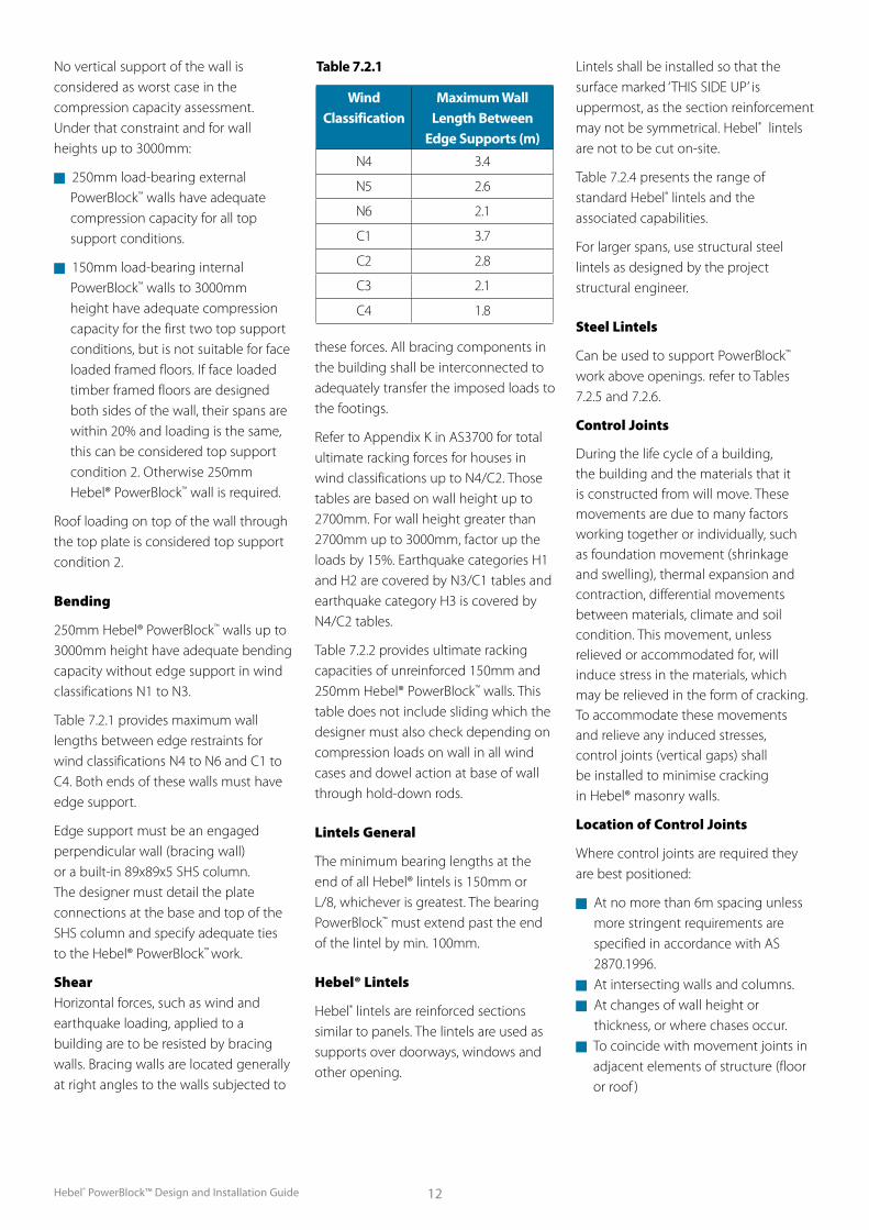
250mm Hebel® PowerBlock™ walls up to 3000mm height have adequate bending capacity without edge support in wind classifications N1 to N3.
Table 7.2.1 provides maximum wall lengths between edge restraints for wind classifications N4 to N6 and C1 to C4. Both ends of these walls must have edge support.
Edge support must be an engaged perpendicular wall (bracing wall) or a built-in 89x89x5 SHS column. The designer must detail the plate connections at the base and top of the SHS column and specify adequate ties to the Hebel® PowerBlock™ work.
Shear Horizontal forces, such as wind and earthquake loading, applied to a building are to be resisted by bracing walls. Bracing walls are located generally at right angles to the walls subjected to
these forces. All bracing components in the building shall be interconnected to adequately transfer the imposed loads to the footings.
Refer to Appendix K in AS3700 for total ultimate racking forces for houses in wind classifications up to N4/C2. Those tables are based on wall height up to 2700mm. For wall height greater than 2700mm up to 3000mm, factor up the loads by 15%. Earthquake categories H1 and H2 are covered by N3/C1 tables and earthquake category H3 is covered by N4/C2 tables.
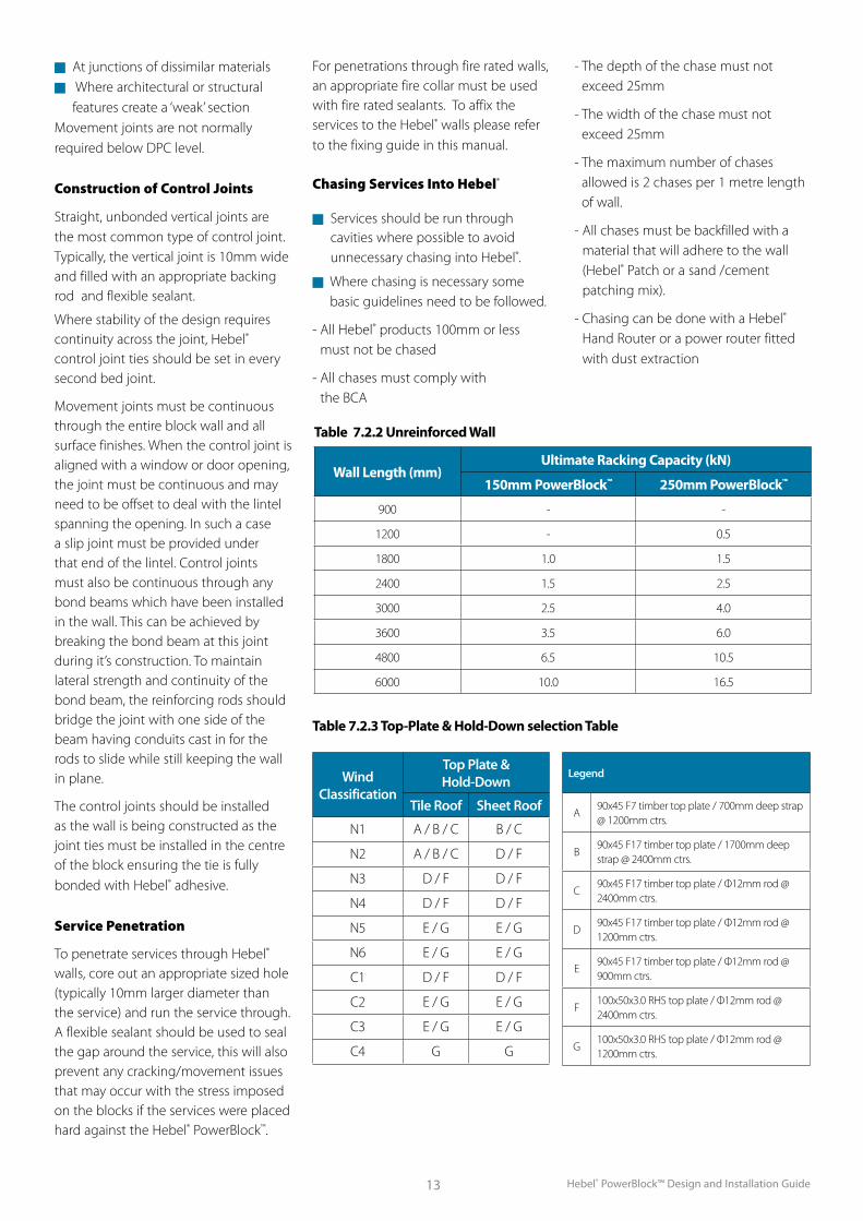
Table 7.2.2 provides ultimate racking capacities of unreinforced 150mm and 250mm Hebel® PowerBlock™ walls. This table does not include sliding which the designer must also check depending on compression loads on wall in all wind cases and dowel action at base of wall through hold-down rods.
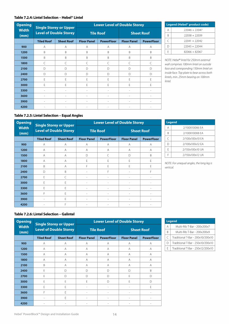
Lintels General
The minimum bearing lengths at the end of all Hebel® lintels is 150mm or L/8, whichever is greatest. The bearing PowerBlock™ must extend past the end of the lintel by min. 100mm.
Hebel® Lintels
Hebel® lintels are reinforced sections similar to panels. The lintels are used as supports over doorways, windows and other opening.
Lintels shall be installed so that the surface marked ‘THIS SIDE UP’ is uppermost, as the section reinforcement may not be symmetrical. Hebel® lintels are not to be cut on-site.
Table 7.2.4 presents the range of standard Hebel® lintels and the associated capabilities.
For larger spans, use structural steel lintels as designed by the project structural engineer.
Steel Lintels
Can be used to support PowerBlock™ work above openings. refer to Tables 7.2.5 and 7.2.6.
Control Joints
During the life cycle of a building, the building and the materials that it is constructed from will move. These movements are due to many factors working together or individually, such as foundation movement (shrinkage and swelling), thermal expansion and contraction, differential movements between materials, climate and soil condition. This movement, unless relieved or accommodated for, will induce stress in the materials, which may be relieved in the form of cracking. To accommodate these movements and relieve any induced stresses, control joints (vertical gaps) shall be installed to minimise cracking in Hebel® masonry walls.
Location of Control Joints
Where control joints are required they are best positioned:
n At no more than 6m spacing unless more stringent requirements are specified in accordance with AS 2870.1996.
n At intersecting walls and columns.n At changes of wall height or
thickness, or where chases occur.n To coincide with movement joints in
adjacent elements of structure (floor or roof )
Table 7.2.1
Wind Classification
Maximum Wall Length Between
Edge Supports (m)
N4 3.4
N5 2.6
N6 2.1
C1 3.7
C2 2.8
C3 2.1
C4 1.8
Hebel® PowerBlock™ Design and Installation Guide13
n At junctions of dissimilar materialsn Where architectural or structural
features create a ‘weak’ sectionMovement joints are not normally required below DPC level.
Construction of Control Joints
Straight, unbonded vertical joints are the most common type of control joint. Typically, the vertical joint is 10mm wide and filled with an appropriate backing rod and flexible sealant.
Where stability of the design requires continuity across the joint, Hebel® control joint ties should be set in every second bed joint.
Movement joints must be continuous through the entire block wall and all surface finishes. When the control joint is aligned with a window or door opening, the joint must be continuous and may need to be offset to deal with the lintel spanning the opening. In such a case a slip joint must be provided under that end of the lintel. Control joints must also be continuous through any bond beams which have been installed in the wall. This can be achieved by breaking the bond beam at this joint during it’s construction. To maintain lateral strength and continuity of the bond beam, the reinforcing rods should bridge the joint with one side of the beam having conduits cast in for the rods to slide while still keeping the wall in plane.
The control joints should be installed as the wall is being constructed as the joint ties must be installed in the centre of the block ensuring the tie is fully bonded with Hebel® adhesive.
Service Penetration
To penetrate services through Hebel® walls, core out an appropriate sized hole (typically 10mm larger diameter than the service) and run the service through. A flexible sealant should be used to seal the gap around the service, this will also prevent any cracking/movement issues that may occur with the stress imposed on the blocks if the services were placed hard against the Hebel® PowerBlock™.
For penetrations through fire rated walls, an appropriate fire collar must be used with fire rated sealants. To affix the services to the Hebel® walls please refer to the fixing guide in this manual.
Chasing Services Into Hebel®
n Services should be run through cavities where possible to avoid unnecessary chasing into Hebel®.
n Where chasing is necessary some basic guidelines need to be followed.
- All Hebel® products 100mm or less must not be chased
- All chases must comply with the BCA
Table 7.2.2 Unreinforced Wall
Wall Length (mm)Ultimate Racking Capacity (kN)
150mm PowerBlock™ 250mm PowerBlock™
900 - -
1200 - 0.5
1800 1.0 1.5
2400 1.5 2.5
3000 2.5 4.0
3600 3.5 6.0
4800 6.5 10.5
6000 10.0 16.5
- The depth of the chase must not exceed 25mm
- The width of the chase must not exceed 25mm
- The maximum number of chases allowed is 2 chases per 1 metre length of wall.
- All chases must be backfilled with a material that will adhere to the wall (Hebel® Patch or a sand /cement patching mix).
- Chasing can be done with a Hebel® Hand Router or a power router fitted with dust extraction
Wind Classification
Top Plate & Hold-Down
Tile Roof Sheet Roof
N1 A / B / C B / C
N2 A / B / C D / F
N3 D / F D / F
N4 D / F D / F
N5 E / G E / G
N6 E / G E / G
C1 D / F D / F
C2 E / G E / G
C3 E / G E / G
C4 G G
Legend
A90x45 F7 timber top plate / 700mm deep strap @ 1200mm ctrs.
B90x45 F17 timber top plate / 1700mm deep strap @ 2400mm ctrs.
C90x45 F17 timber top plate / Ф12mm rod @ 2400mm ctrs.
D90x45 F17 timber top plate / Ф12mm rod @ 1200mm ctrs.
E90x45 F17 timber top plate / Ф12mm rod @ 900mm ctrs.
F100x50x3.0 RHS top plate / Ф12mm rod @ 2400mm ctrs.
G100x50x3.0 RHS top plate / Ф12mm rod @ 1200mm ctrs.
Table 7.2.3 Top-Plate & Hold-Down selection Table
Hebel® PowerBlock™ Design and Installation Guide 14
Opening Width (mm)
Single Storey or Upper Level of Double Storey
Lower Level of Double Storey
Tile Roof Sheet Roof
Tiled Roof Sheet Roof Floor Panel PowerFloor Floor Panel PowerFloor
900 A A A A A A
1200 A A A A A A
1500 A A D C D B
1800 A A E E E E
2100 B A F E E E
2400 D B - F - F
2700 E C - - - -
3000 E E - - - -
3300 E E - - - -
3600 F E - - - -
3900 - E - - - -
4200 - F - - - -
Opening Width (mm)
Single Storey or Upper Level of Double Storey
Lower Level of Double Storey
Tile Roof Sheet Roof
Tiled Roof Sheet Roof Floor Panel PowerFloor Floor Panel PowerFloor
900 A A A A A A
1200 A A A A A A
1500 A A A A A A
1800 A A A A A A
2100 B A A A A A
2400 E D D D D B
2700 E D D D E D
3000 E E E D E D
3300 E E - - - E
3600 F E - - - -
3900 - E - - - -
4200 - - - - - -
Table 7.2.5: Lintel Selection – Equal Angles
Table 7.2.6: Lintel Selection – Galintel
Legend
A 2/100X100X6 EA
B 2/100X100X8 EA
C 2/100x100x10 EA
D 2/100x100x12 EA
E 2/150x100x10 UA
F 2/150x100x12 UA
NOTE: For unequal angles, the long leg is vertical.
Legend
A Multi-Rib T-Bar - 200x200x7
B Multi-Rib T-Bar - 200x200x9
C Traditional T-Bar - 200x10/200x10
D Traditional T-Bar - 250x10/200x10
E Traditional T-Bar - 250x12/200x10
Opening Width (mm)
Single Storey or Upper Level of Double Storey
Lower Level of Double Storey
Tile Roof Sheet Roof
Tiled Roof Sheet Roof Floor Panel PowerFloor Floor Panel PowerFloor
900 A A A A A A
1200 B B B B B B
1500 B B B B B B
1800 C C C C C C
2100 D D D D D D
2400 D D D D D D
2700 E E E E E E
3000 E E E E E E
3300 - - - - - -
3600 - - - - - -
3900 - - - - - -
4200 - - - - - -
Table 7.2.4: Lintel Selection – Hebel® Lintel
Legend (Hebel® product code)
A 22046 + 22047
B 22038 + 22039
C 22041 + 22042
D 22043 + 22044
E 82066 + 82067
NOTE: Hebel® lintel for 250mm external wall comprises 100mm lintel on outside face and corresponding 150mm lintel on inside face. Top plate to bear across both lintels, min. 25mm bearing on 100mm lintel.
Hebel® PowerBlock™ Design and Installation Guide15
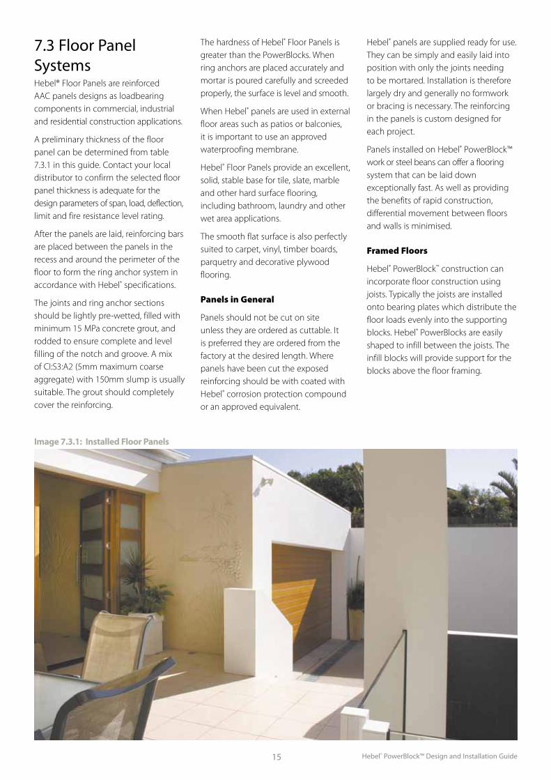
7.3 Floor Panel SystemsHebel® Floor Panels are reinforced AAC panels designs as loadbearing components in commercial, industrial and residential construction applications.
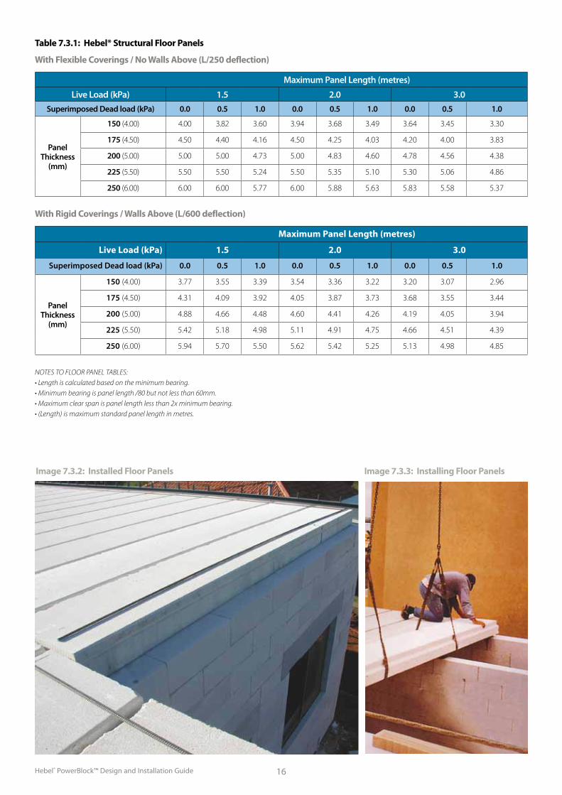
A preliminary thickness of the floor panel can be determined from table 7.3.1 in this guide. Contact your local distributor to confirm the selected floor panel thickness is adequate for the design parameters of span, load, deflection, limit and fire resistance level rating.
After the panels are laid, reinforcing bars are placed between the panels in the recess and around the perimeter of the floor to form the ring anchor system in accordance with Hebel® specifications.
The joints and ring anchor sections should be lightly pre-wetted, filled with minimum 15 MPa concrete grout, and rodded to ensure complete and level filling of the notch and groove. A mix of CI:S3:A2 (5mm maximum coarse aggregate) with 150mm slump is usually suitable. The grout should completely cover the reinforcing.
The hardness of Hebel® Floor Panels is greater than the PowerBlocks. When ring anchors are placed accurately and mortar is poured carefully and screeded properly, the surface is level and smooth.
When Hebel® panels are used in external floor areas such as patios or balconies, it is important to use an approved waterproofing membrane.
Hebel® Floor Panels provide an excellent, solid, stable base for tile, slate, marble and other hard surface flooring, including bathroom, laundry and other wet area applications.
The smooth flat surface is also perfectly suited to carpet, vinyl, timber boards, parquetry and decorative plywood flooring.
Panels in General
Panels should not be cut on site unless they are ordered as cuttable. It is preferred they are ordered from the factory at the desired length. Where panels have been cut the exposed reinforcing should be with coated with Hebel® corrosion protection compound or an approved equivalent.
Hebel® panels are supplied ready for use. They can be simply and easily laid into position with only the joints needing to be mortared. Installation is therefore largely dry and generally no formwork or bracing is necessary. The reinforcing in the panels is custom designed for each project.
Panels installed on Hebel® PowerBlock™ work or steel beans can offer a flooring system that can be laid down exceptionally fast. As well as providing the benefits of rapid construction, differential movement between floors and walls is minimised.
Framed Floors
Hebel® PowerBlock™ construction can incorporate floor construction using joists. Typically the joists are installed onto bearing plates which distribute the floor loads evenly into the supporting blocks. Hebel® PowerBlocks are easily shaped to infill between the joists. The infill blocks will provide support for the blocks above the floor framing.
Image 7.3.1: Installed Floor Panels
Hebel® PowerBlock™ Design and Installation Guide 16
Table 7.3.1: Hebel® Structural Floor Panels
Image 7.3.2: Installed Floor Panels Image 7.3.3: Installing Floor Panels
With Flexible Coverings / No Walls Above (L/250 deflection)
Maximum Panel Length (metres)
Live Load (kPa) 1.5 2.0 3.0Superimposed Dead load (kPa) 0.0 0.5 1.0 0.0 0.5 1.0 0.0 0.5 1.0
Panel Thickness
(mm)
150 (4.00) 4.00 3.82 3.60 3.94 3.68 3.49 3.64 3.45 3.30
175 (4.50) 4.50 4.40 4.16 4.50 4.25 4.03 4.20 4.00 3.83
200 (5.00) 5.00 5.00 4.73 5.00 4.83 4.60 4.78 4.56 4.38
225 (5.50) 5.50 5.50 5.24 5.50 5.35 5.10 5.30 5.06 4.86
250 (6.00) 6.00 6.00 5.77 6.00 5.88 5.63 5.83 5.58 5.37
With Rigid Coverings / Walls Above (L/600 deflection)
Maximum Panel Length (metres)
Live Load (kPa) 1.5 2.0 3.0
Superimposed Dead load (kPa) 0.0 0.5 1.0 0.0 0.5 1.0 0.0 0.5 1.0
Panel Thickness
(mm)
150 (4.00) 3.77 3.55 3.39 3.54 3.36 3.22 3.20 3.07 2.96
175 (4.50) 4.31 4.09 3.92 4.05 3.87 3.73 3.68 3.55 3.44
200 (5.00) 4.88 4.66 4.48 4.60 4.41 4.26 4.19 4.05 3.94
225 (5.50) 5.42 5.18 4.98 5.11 4.91 4.75 4.66 4.51 4.39
250 (6.00) 5.94 5.70 5.50 5.62 5.42 5.25 5.13 4.98 4.85
NOTES TO FLOOR PANEL TABLES: • Length is calculated based on the minimum bearing. • Minimum bearing is panel length /80 but not less than 60mm. • Maximum clear span is panel length less than 2x minimum bearing. • (Length) is maximum standard panel length in metres.
Hebel® PowerBlock™ Design and Installation Guide17
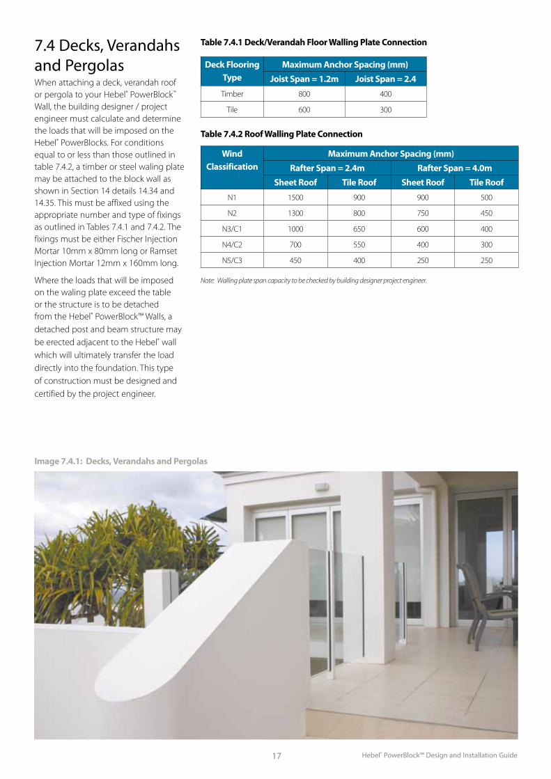
Table 7.4.1 Deck/Verandah Floor Walling Plate Connection
Deck Flooring Type
Maximum Anchor Spacing (mm)
Joist Span = 1.2m Joist Span = 2.4
Timber 800 400
Tile 600 300
Table 7.4.2 Roof Walling Plate Connection
Wind Classification
Maximum Anchor Spacing (mm)
Rafter Span = 2.4m Rafter Span = 4.0m
Sheet Roof Tile Roof Sheet Roof Tile Roof
N1 1500 900 900 500
N2 1300 800 750 450
N3/C1 1000 650 600 400
N4/C2 700 550 400 300
N5/C3 450 400 250 250
Note: Walling plate span capacity to be checked by building designer project engineer.
Image 7.4.1: Decks, Verandahs and Pergolas
7.4 Decks, Verandahs and PergolasWhen attaching a deck, verandah roof or pergola to your Hebel® PowerBlock™ Wall, the building designer / project engineer must calculate and determine the loads that will be imposed on the Hebel® PowerBlocks. For conditions equal to or less than those outlined in table 7.4.2, a timber or steel waling plate may be attached to the block wall as shown in Section 14 details 14.34 and 14.35. This must be affixed using the appropriate number and type of fixings as outlined in Tables 7.4.1 and 7.4.2. The fixings must be either Fischer Injection Mortar 10mm x 80mm long or Ramset Injection Mortar 12mm x 160mm long.
Where the loads that will be imposed on the waling plate exceed the table or the structure is to be detached from the Hebel® PowerBlock™ Walls, a detached post and beam structure may be erected adjacent to the Hebel® wall which will ultimately transfer the load directly into the foundation. This type of construction must be designed and certified by the project engineer.
Hebel® PowerBlock™ Design and Installation Guide 18
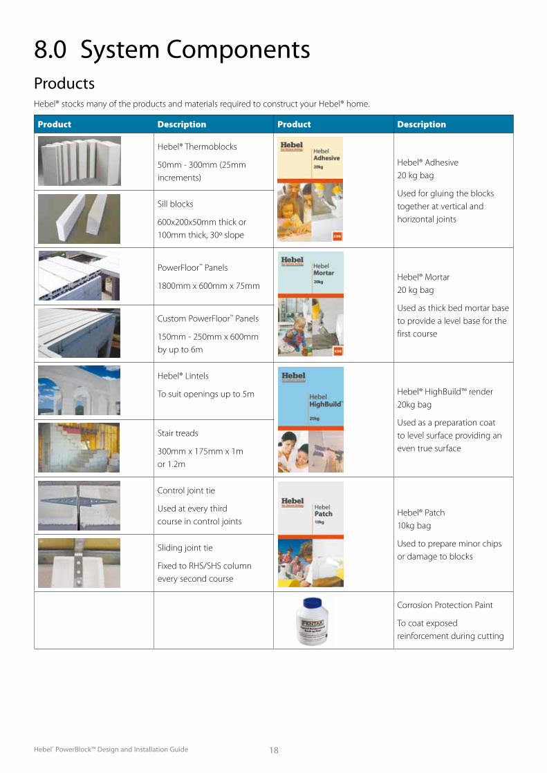
ProductsHebel® stocks many of the products and materials required to construct your Hebel® home.
Product Description Product Description
Hebel® Thermoblocks
50mm - 300mm (25mm increments)
Hebel® Adhesive 20 kg bag
Used for gluing the blocks together at vertical and horizontal joints
Sill blocks
600x200x50mm thick or 100mm thick, 30º slope
PowerFloor™ Panels
1800mm x 600mm x 75mmHebel® Mortar 20 kg bag
Used as thick bed mortar base to provide a level base for the first course
Custom PowerFloor™ Panels
150mm - 250mm x 600mm by up to 6m
Hebel® Lintels
To suit openings up to 5m Hebel® HighBuild™ render 20kg bag
Used as a preparation coat to level surface providing an even true surface
Stair treads
300mm x 175mm x 1m or 1.2m
Control joint tie
Used at every third course in control joints
Hebel® Patch 10kg bag
Used to prepare minor chips or damage to blocks
Sliding joint tie
Fixed to RHS/SHS column every second course
Corrosion Protection Paint
To coat exposed reinforcement during cutting
8.0 System Components
Hebel® PowerBlock™ Design and Installation Guide19
9.0 Construction NotesGeneral Notes
1. These notes and details are to be read in conjunction with the project’s contract documentation.
2. All materials and workmanship shall be in accordance with this Installation Guide, the current edition of the Hebel® Technical Manual and other Hebel® documentation.
3. Refer to architectural drawings for all setting out dimensions.
4. Do not scale drawings, use written dimensions.
5. Should any omission, penetration, cutting of panels, discrepancy or fault exist, contact the designer
immediately for a decision before proceeding with work.
6. All load-bearing walls, bearing on Hebel® floor panels, shall be supported separately in accordance with the project engineer’s design.
7. Hebel® accepts no responsibility for the design or selection of supporting walls, lintels, beams, columns or other structural members.
9. Corrosion protection of all structural steelworks shall be specified by the project engineer or architect.
10. The temporary restraint of walls is the responsibility of the builder or installer.
11. PowerBlocks on site should be protected against rain and water saturation. This can best be achieved by leaving the shrink-wrap cap on the top of pallets and covering the top of blockwork if rain threatens. PowerBlocks should not be laid in the rain.
IMPORTANT12. Ensure engineering tie-down rods are
present and located in accordance with the engineer’s documentation.
13. Ensure control joint locations are marked out in accordance with the engineering documentation.
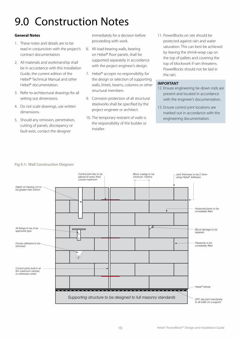
Depth of chasing not to be greater than 25mm
All fixings to be of an approved type
Control joint ties to be placed at every third course maximum
Block overlap to be minimum 100mm
Joint thickness to be 2-3mm using Hebel® Adhesive
Horizontal joints to be completely filled
Block damage to be repaired
Perpends to be completely filled
Hebel® Mortar
DPC slip joint membrane to all walls on a support
Excess adhesive to be removed
Control joints built in at 6m maximum centres or otherwise noted
Supporting structure to be designed to full masonry standards
Fig 9.1: Wall Construction Diagram
Hebel® PowerBlock™ Design and Installation Guide 20
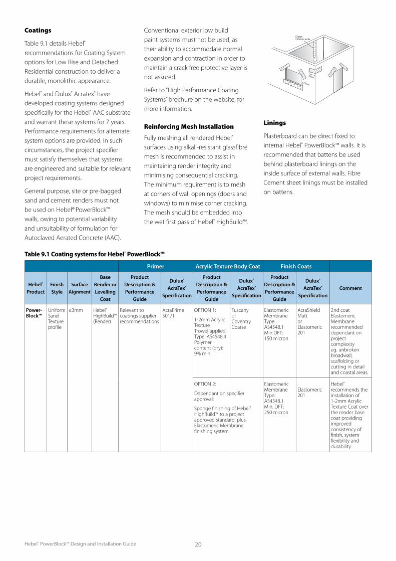
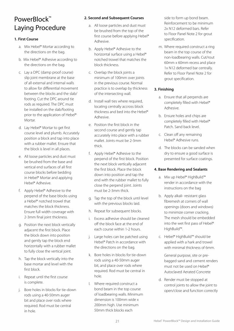
Coatings
Table 9.1 details Hebel® recommendations for Coating System options for Low Rise and Detached Residential construction to deliver a durable, monolithic appearance.
Hebel® and Dulux® Acratex® have developed coating systems designed specifically for the Hebel® AAC substrate and warrant these systems for 7 years. Performance requirements for alternate system options are provided. In such circumstances, the project specifier must satisfy themselves that systems are engineered and suitable for relevant project requirements.
General purpose, site or pre-bagged sand and cement renders must not be used on Hebel® PowerBlock™ walls, owing to potential variability and unsuitability of formulation for Autoclaved Aerated Concrete (AAC).
Conventional exterior low build paint systems must not be used, as their ability to accommodate normal expansion and contraction in order to maintain a crack free protective layer is not assured.
Refer to “High Performance Coating Systems” brochure on the website, for more information.
Reinforcing Mesh Installation
Fully meshing all rendered Hebel® surfaces using alkali-resistant glassfibre mesh is recommended to assist in maintaining render integrity and minimising consequential cracking. The minimum requirement is to mesh at corners of wall openings (doors and windows) to minimise corner cracking. The mesh should be embedded into the wet first pass of Hebel® HighBuild™.
Linings
Plasterboard can be direct fixed to internal Hebel® PowerBlock™ walls. It is recommended that battens be used behind plasterboard linings on the inside surface of external walls. Fibre Cement sheet linings must be installed on battens.
Table 9.1 Coating systems for Hebel® PowerBlock™
250mm
600mm
Chase150mm wide
Primer Acrylic Texture Body Coat Finish Coats
Hebel® Product
Finish Style
Surface Aignment
Base Render or Levelling
Coat
Product Description & Performance
Guide
Dulux® AcraTex®
Specification
Product Description & Performance
Guide
Dulux® AcraTex®
Specification
Product Description & Performance
Guide
Dulux® AcraTex®
SpecificationComment
Power- Block™
Uniform Sand Texture profile
≤3mm Hebel® HighBuild™ (Render)
Relevant to coatings supplier recommendations
AcraPrime 501/1
OPTION 1:
1-2mm Acrylic Texture Trowel applied Type: AS4548.4 Polymer content (dry): 9% min.
Tuscany or Coventry Coarse
Elastomeric Membrane Type: AS4548.1 Min DFT: 150 micron
AcraShield Matt or Elastomeric 201
2nd coat Elastomeric Membrane recommended dependant on project complexity eg. unbroken broadwall, scaffolding or cutting in detail and coastal areas.
OPTION 2:
Dependant on specifier approval:
Sponge finishing of Hebel® HighBuild™ to a project approved standard; plus Elastomeric Membrane finishing system.
Elastomeric Membrane Type: AS4548.1 Min. DFT: 250 micron
Elastomeric 201
Hebel® recommends the installation of 1-2mm Acrylic Texture Coat over the render base coat providing improved consistency of finish, system flexibility and durability.
Hebel® PowerBlock™ Design and Installation Guide21
PowerBlock™ Laying Procedure
1. First Course
a. Mix Hebel® Mortar according to the directions on the bag.
b. Mix Hebel® Adhesive according to the directions on the bag.
c. Lay a DPC (damp proof course) slip joint membrane at the base of all external and internal walls to allow for differential movement between the blocks and the slab/ footing. Cut the DPC around tie rods as required. The DPC must be installed on the slab/footing prior to the application of Hebel® Mortar.
d. Lay Hebel® Mortar to get first course level and plumb. Accurately position a block and tap into place with a rubber mallet. Ensure that the block is level in all places.
e. All loose particles and dust must be brushed from the base and vertical end surfaces of all first course blocks before bedding in Hebel® Mortar and applying Hebel® Adhesive.
f. Apply Hebel® Adhesive to the perpend of the base blocks using a Hebel® notched trowel that matches the block thickness. Ensure full width coverage with 2-3mm final joint thickness.
g. Position the next block vertically adjacent the first block. Place the block down into position and gently tap the block end horizontally with a rubber mallet to fully close the vertical joint.
h. Tap the block vertically into the base mortar and level with the first block.
i. Repeat until the first course is complete.
j. Bore holes in blocks for tie-down rods using a 40-50mm auger bit and place over rods where required. Rod must be central in hole.
2. Second and Subsequent Courses
a. All loose particles and dust must be brushed from the top of the first course before applying Hebel® Adhesive.
b. Apply Hebel® Adhesive to the horizontal surface using a Hebel® notched trowel that matches the block thickness.
c. Overlap the block joints a minimum of 100mm over joints in the previous course. Normal practice is to overlap by thickness of the intersecting wall.
d. Install wall ties where required, locating centrally accross block thickness and bed into the Hebel® Adhesive.
e. Position the first block in the second course and gently tap accurately into place with a rubber mallet. Joints must be 2-3mm thick.
f. Apply Hebel® Adhesive to the perpend of the first block. Position the next block vertically adjacent the first block. Place the block down into position and tap the end with the rubber mallet to fully close the perpend joint. Joints must be 2-3mm thick.
g. Tap the top of the block until level with the previous blocks laid.
h. Repeat for subsequent blocks.
i. Excess adhesive should be cleaned off the block face at the end of each course within 1-2 hours.
j. Large holes can be patched using Hebel® Patch in accordance with the directions on the bag.
k. Bore holes in blocks for tie-down rods using a 40-50mm auger bit, and place over rods where required. Rod must be central in hole.
l. Where required construct a bond beam in the top course of loadbearing walls. Minimum dimension is 100mm wide x 200mm high. Use minimum 50mm thick blocks each
side to form up bond beam. Reinforcement to be minimum 2x N12 deformed bars. Refer to Floor Panel Note 2 for grout specification.
m. Where required construct a ring beam in the top course of the non-loadbearing walls. Cut/rout 60mm x 60mm recess and place 1x N12 deformed bar centrally. Refer to Floor Panel Note 2 for grout specification.
3. Finishing
a. Ensure that all perpends are completely filled with Hebel® Adhesive.
b. Ensure holes and chips are completely filled with Hebel® Patch. Sand back level.
c. Clean off any remaining Hebel® Adhesive runs.
d. The blocks can be sanded when dry to ensure a good surface is presented for surface coatings.
4. Base Rendering and Sealants
a. Mix up Hebel® HighBuild™ render in accordance with the instructions on the bag
b. Apply alkali- resistant glass fibremesh at corners of wall openings (doors and windows) to minimize corner cracking. The mesh should be embedded into the wet first pass of Hebel® HighBuild™.
c. Hebel® HighBuild™ should be applied with a hark and trowel with minimal thickness of 6mm.
General purpose, site or pre-bagged sand and cement renders must not be used on Hebel® Autoclaved Aerated Concrete
d. Render must be stopped at control joints to allow the joint to open/close and function correctly
Hebel® PowerBlock™ Design and Installation Guide 22
e. All control joints and gaps between blockwork and framing around windows must be caulked with an appropriate flexible sealant
f. Install backing rods approx 10mm from surface
g. Apply primer to the surfaces
h. Installed sealants to manufacturer’s specifications
5. Coatings for External Walls
a. Coatings must comprise a high build acrylic texture coat and finish elastomeric paint membrane
b. Conventional exterior low build paint must not be used
c. Allow Hebel® HighBuild™ to fully cure (approx 24 hours depending on weather conditions)
d. Apply primer to the Hebel® HighBuild™
e. Apply texture body coat such as Dulux® AcraTex®. Ensure texture coat stops at control joints.
f. Apply finishing sealants in control joints
g. Apply first finishing paint elastomeric paint membrane
h. Apply second coat of elastomeric paint membrane as required
i. Refer to manfuacturer’s guidline for coating on AAC PowerBlock™ work and Hebel® HighBuild™
6. Internal Linings
a. Plasterboard can be direct fixed to internal Hebel® PowerBlock™ walls.
b. It is recommended that battens be used behind plasterboard linings on the inside surface of external Hebel® PowerBlock™ walls.
c. Fibre cement sheet linings can not be direct fixed to Hebel® PowerBlocks. Installed fibre cement sheets linings on battens
d. Hebel® HighBuild™ render may be directly applied to internal block walls as per pervious instructions.
Floor Panel Notes1. The ring anchor reinforcement
shall be a minimum of N12 grade in accordance with AS1302, unless noted otherwise by the project engineer.
2. Hebel® Mortar should be used as grout for the ring anchor system. A nominal composition of 1 Cement: 4 Sand (5mm maximum coarse aggregate) can also be used. Minimum compression strength of f ’cg= 15MPa at 28 days.
3. Additives to reduce the grout shrinkage shall only be used in accordance with the manufacturer’s instructions.
4. The installer shall support (chair) reinforcement to enable grout to fully surround the reinforcement. Reinforcement shall not be in contact with the panel when grout is placed.
5. Grout shall be rodded to ensure complete filling of notch and groove.
6. The installer shall provide notch and groove at panel joints as per Hebel® standard detail 5.3.5 on page 7.60 in the Hebel® Technical Manual..
7. Ensure notch is cleared of all loose material and reinforcement cleaned of all foreign material.
8. Lightly pre-wet notch prior to pouring the grout.
9. Panels shall only be cut on-site as indicated on the engineer’s drawings,
otherwise contact your distributor or sales representative.
10. Propping of panels may be required to accommodate minor misalignments until 3 days after ring anchor grout is poured.
11. All propping shall be removed from Hebel® Floor Panels before any walls are erected over.
12. Traffic on floor panels is to be avoided for a period of 3 days after the ring anchor grout is poured.
13. All panel dimensions are the responsibility of Hebel’s client and are subject to approval by the client before commencing manufacture of panels.

Hebel® PowerBlock™ Design and Installation Guide23
10.0 Tools & Equipment for ConstructionHebel® PowerBlocks can be laid using construction tools/equipment.
String Line – A string line is required to accurately set out and lay Hebel® PowerBlock™ Walls.
Brick/Blocklaying Profiles – used to gauge the block course are being laid level.
Mixing Bucket – a minimum 20 litre bucket is required for mixing Hebel® Mortar, Hebel® Adhesive and Hebel® HighBuild™ render.
Electric Drill – an electric drill is required to mix the Hebel® Mortar, Hebel® Adhesive and Hebel® HighBuild™ render. It is also used to drill clearance holes in the blocks so they can be placed over the tied down rods where required.
Stirrer – fitted to the electric drill, the stirrer is used to mix the Hebel® Mortar, Hebel® Adhesive and Hebel® HighBuild™ render inside the mixing bucket.
Notched Trowel – the notched trowel is used to apply the Hebel® Adhesive to the Hebel® surfaces. The width of the trowel must match the block thickness to ensure the adhesive is applied with full and even coverage.
Rubber Mallet – a rubber mallet is required to ‘tap’ the Hebel® PowerBlocks onto the adhesive and into place.
Spirit Level – required to install the blocks level and plumb.
Hand Saw – a Hebel® handsaw can be used to cut Hebel® PowerBlocks to length and height.
Powered Bandsaw – a bandsaw is ideal for cutting Hebel® PowerBlocks. (perfect when there are many site cuts to be performed).
Hebel® Square – a purpose built square is available for use when marking and cutting Hebel® PowerBlocks.
Steel, Plastic and Timber Trowels – these trowels may be required for the installation of the Highbuild render and texture coatings.
Sanding Float – used to even out inconsistencies in the Hebel® PowerBlock™ Wall in preparation for render/texture coats.
Hebel® Hand Router – may be used to chase services into solid Hebel® walls.
Circular Saw – (fitted with a diamond blade) may be used to chase services into solid Hebel® walls.
Electric Router – may be used to chase services into solid Hebel® walls.
Crane – may be required to lift large Hebel® Lintels and Hebel® custom floor panels.
Lifting Grabs – required for use in conjunction with crane for lifting Hebel® lintels and custom floor panels.
Scaffold – Scaffold is required when building block walls. The amount of scaffold depends on the height of the walls.
Sealant Gun – required to fill the control joints in the Hebel® PowerBlock™ Walls.
Image 10.1: Hebel® tools
Hebel® PowerBlock™ Design and Installation Guide 24
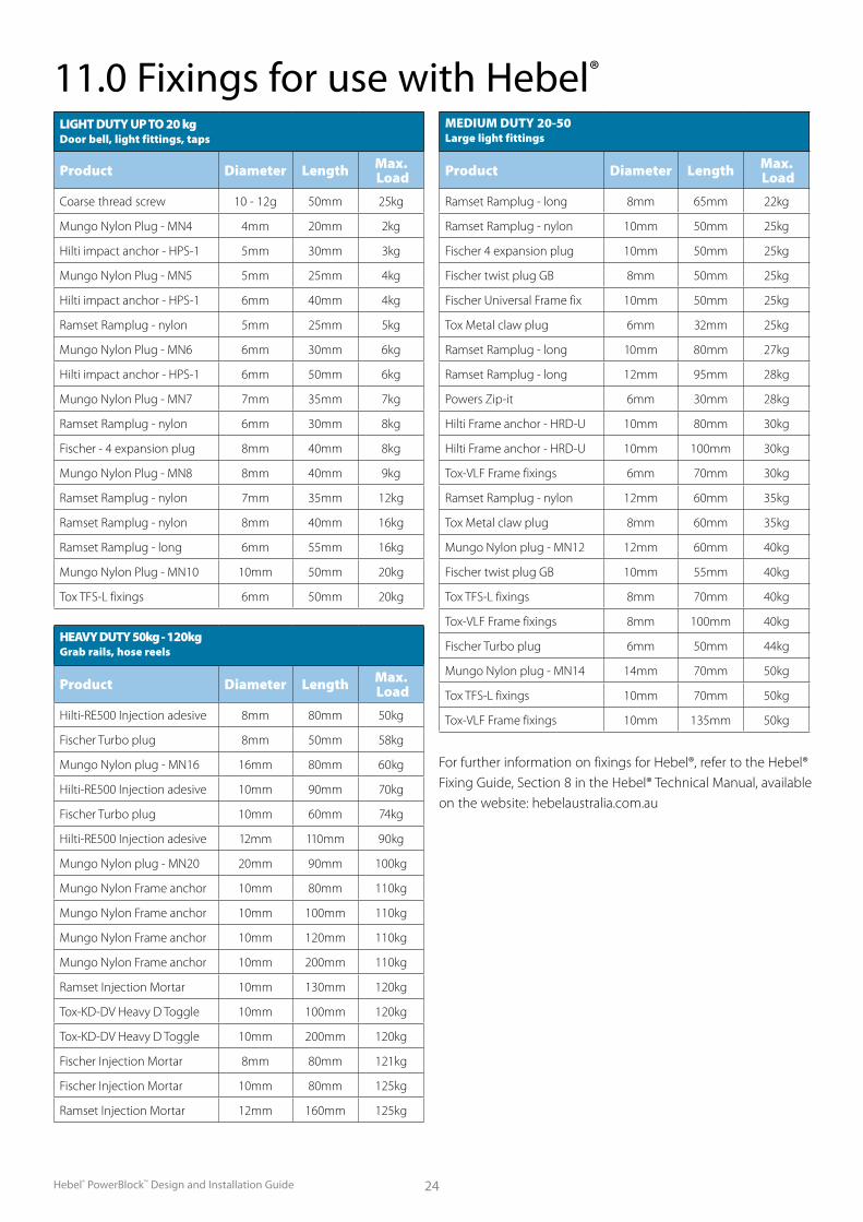
11.0 Fixings for use with Hebel®
LIGHT DUTY UP TO 20 kg Door bell, light fittings, taps.
Product Diameter Length Max. Load
Coarse thread screw 10 - 12g 50mm 25kg
Mungo Nylon Plug - MN4 4mm 20mm 2kg
Hilti impact anchor - HPS-1 5mm 30mm 3kg
Mungo Nylon Plug - MN5 5mm 25mm 4kg
Hilti impact anchor - HPS-1 6mm 40mm 4kg
Ramset Ramplug - nylon 5mm 25mm 5kg
Mungo Nylon Plug - MN6 6mm 30mm 6kg
Hilti impact anchor - HPS-1 6mm 50mm 6kg
Mungo Nylon Plug - MN7 7mm 35mm 7kg
Ramset Ramplug - nylon 6mm 30mm 8kg
Fischer - 4 expansion plug 8mm 40mm 8kg
Mungo Nylon Plug - MN8 8mm 40mm 9kg
Ramset Ramplug - nylon 7mm 35mm 12kg
Ramset Ramplug - nylon 8mm 40mm 16kg
Ramset Ramplug - long 6mm 55mm 16kg
Mungo Nylon Plug - MN10 10mm 50mm 20kg
Tox TFS-L fixings 6mm 50mm 20kg
MEDIUM DUTY 20-50 Large light fittings
Product Diameter Length Max. Load
Ramset Ramplug - long 8mm 65mm 22kg
Ramset Ramplug - nylon 10mm 50mm 25kg
Fischer 4 expansion plug 10mm 50mm 25kg
Fischer twist plug GB 8mm 50mm 25kg
Fischer Universal Frame fix 10mm 50mm 25kg
Tox Metal claw plug 6mm 32mm 25kg
Ramset Ramplug - long 10mm 80mm 27kg
Ramset Ramplug - long 12mm 95mm 28kg
Powers Zip-it 6mm 30mm 28kg
Hilti Frame anchor - HRD-U 10mm 80mm 30kg
Hilti Frame anchor - HRD-U 10mm 100mm 30kg
Tox-VLF Frame fixings 6mm 70mm 30kg
Ramset Ramplug - nylon 12mm 60mm 35kg
Tox Metal claw plug 8mm 60mm 35kg
Mungo Nylon plug - MN12 12mm 60mm 40kg
Fischer twist plug GB 10mm 55mm 40kg
Tox TFS-L fixings 8mm 70mm 40kg
Tox-VLF Frame fixings 8mm 100mm 40kg
Fischer Turbo plug 6mm 50mm 44kg
Mungo Nylon plug - MN14 14mm 70mm 50kg
Tox TFS-L fixings 10mm 70mm 50kg
Tox-VLF Frame fixings 10mm 135mm 50kg
For further information on fixings for Hebel®, refer to the Hebel® Fixing Guide, Section 8 in the Hebel® Technical Manual, available on the website: hebelaustralia.com.au
HEAVY DUTY 50kg - 120kg Grab rails, hose reels
Product Diameter Length Max. Load
Hilti-RE500 Injection adesive 8mm 80mm 50kg
Fischer Turbo plug 8mm 50mm 58kg
Mungo Nylon plug - MN16 16mm 80mm 60kg
Hilti-RE500 Injection adesive 10mm 90mm 70kg
Fischer Turbo plug 10mm 60mm 74kg
Hilti-RE500 Injection adesive 12mm 110mm 90kg
Mungo Nylon plug - MN20 20mm 90mm 100kg
Mungo Nylon Frame anchor 10mm 80mm 110kg
Mungo Nylon Frame anchor 10mm 100mm 110kg
Mungo Nylon Frame anchor 10mm 120mm 110kg
Mungo Nylon Frame anchor 10mm 200mm 110kg
Ramset Injection Mortar 10mm 130mm 120kg
Tox-KD-DV Heavy D Toggle 10mm 100mm 120kg
Tox-KD-DV Heavy D Toggle 10mm 200mm 120kg
Fischer Injection Mortar 8mm 80mm 121kg
Fischer Injection Mortar 10mm 80mm 125kg
Ramset Injection Mortar 12mm 160mm 125kg
Hebel® PowerBlock™ Design and Installation Guide25
PowerBlock™ DeliveryPowerBlock™ pallets should be unloaded and moved with only approved lifting devices. Before use, the lifting devices should be checked for the required lifting tags. PowerBlock™ pallets should be unloaded and stored as close to the intended installation area as possible. This will increase work efficiency and minimise the need for secondary lifting.
It is good practice to inspect the delivery for damaged blocks. Unnecessary handling will increase the risk of damage to the Hebel® PowerBlocks.
Care should be taken when cutting the packaging straps, blocks may come away and cause injury or become damaged.
TIP - When a block is damaged it may be possible to cut away the damaged section and use the remaining portion in the wall.
StorageAll materials must be kept dry and preferably stored undercover. Hebel® PowerBlocks should be left on their pallet until they are required. Place the pallet on a level and stable surface. The project engineer should be consulted as to the adequacy of the structure to support Hebel® PowerBlocks if they are not stored directly on the ground or concrete slab.
13.0 Delivery & Storage
12.0 PowerBlock™ HandlingManual HandlingTo minimise the possibility of manual handling injuries, Hebel® suggests the following:
Use mechanical aids, such as trolleys, forklifts, cranes and levers, or team lifting to move Hebel®.
Keep the work place clean to reduce the risk of slips, trips and falls, which can cause injury.
Plan the sequence of installation to minimise panel movements and avoid awkward lifts.
Good lifting techniques to be adopted to minimise the risk of injury.
Mechanically Assisted HandlingMoving and handling Hebel® Floor Panels and Hebel® Lintels should be done using mechanical aids such us forklifts, cranes and special panel lifting trolleys. Different panel lift attachments are available for installing panels. For purchasing or hire of these devices please contact CSR Panel Systems.
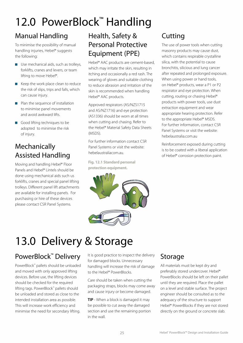
Health, Safety & Personal Protective Equipment (PPE)Hebel® AAC products are cement-based, which may irritate the skin, resulting in itching and occasionally a red rash. The wearing of gloves and suitable clothing to reduce abrasion and irritation of the skin is recommended when handling Hebel® AAC products.
Approved respirators (AS/NZS1715 and AS/NZ1716) and eye protection (AS1336) should be worn at all times when cutting and chasing. Refer to the Hebel® Material Safety Data Sheets (MSDS).
For further information contact CSR Panel Systems or visit the website: hebelaustraliacom.au.
CuttingThe use of power tools when cutting masonry products may cause dust, which contains respirable crystalline silica, with the potential to cause bronchitis, silicious and lung cancer after repeated and prolonged exposure. When using power or hand tools, on Hebel® products, wear a P1 or P2 respirator and eye protection. When cutting, routing or chasing Hebel® products with power tools, use dust extraction equipment and wear appropriate hearing protection. Refer to the appropriate Hebel® MSDS. For further information, contact CSR Panel Systems or visit the website: hebelaustralia.com.au
Reinforcement exposed during cutting is to be coated with a liberal application of Hebel® corrosion protection paint.
Fig. 12.1 Standard personal protection equipment.
Hebel® PowerBlock™ Design and Installation Guide 26
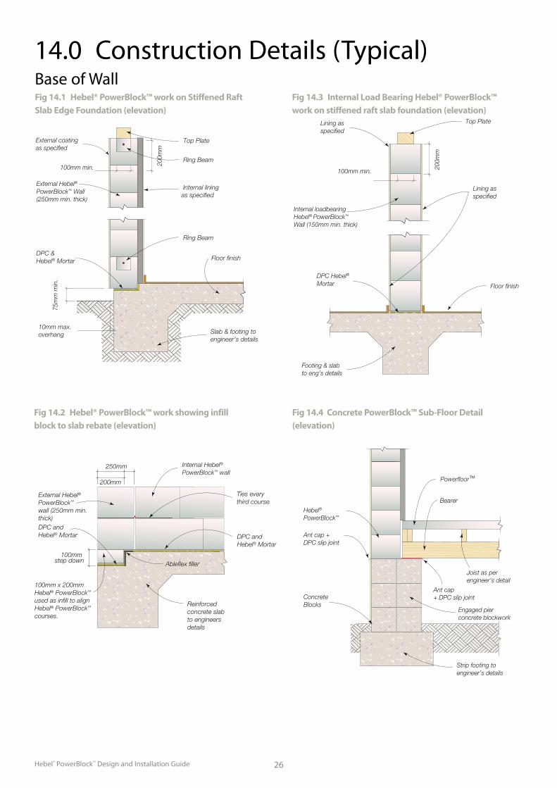
14.0 Construction Details (Typical)
Fig 14.1 Hebel® PowerBlock™ work on Stiffened Raft Slab Edge Foundation (elevation)
Fig 14.2 Hebel® PowerBlock™ work showing infill block to slab rebate (elevation)
Fig 14.3 Internal Load Bearing Hebel® PowerBlock™ work on stiffened raft slab foundation (elevation)
Internal liningas specified
Top Plate
Floor finish
Slab & footing toengineer’s details
10mm max.overhang
DPC & Hebel® Mortar
75m
m m
in.
External Hebel®
PowerBlock™ Wall(250mm min. thick)
External coating as specified
100mm min. 200m
m
Ring Beam
Ring Beam
Reinforced concrete slabto engineersdetails
Ableflex filler
DPC and Hebel® Mortar
100mm x 200mm Hebel® PowerBlock™ used as infill to align Hebel® PowerBlock™ courses.
DPC and Hebel® Mortar
External Hebel® PowerBlock™ wall (250mm min. thick)
Ties every third course
Internal Hebel® PowerBlock™ wall
250mm
200mm
100mm step down
Internal loadbearingHebel® PowerBlock™ Wall (150mm min. thick)
DPC Hebel®
Mortar
Footing & slabto eng’s details
Lining as specified
100mm min. 200m
m
Lining as specified
Top Plate
Floor finish
Base of Wall
Fig 14.4 Concrete PowerBlock™ Sub-Floor Detail (elevation)
Powerfloor™
Hebel®
PowerBlock™
Ant cap +DPC slip joint
ConcreteBlocks
Engaged pierconcrete blockwork
Bearer
Ant cap + DPC slip joint
Strip footing to engineer’s details
Joist as perengineer’s detail
Hebel® PowerBlock™ Design and Installation Guide27
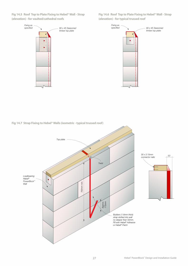
Fig 14.5 Roof Top to Plate Fixing to Hebel® Wall - Strap (elevation) - for vaulted/cathedral roofs
Fig 14.6 Roof Top to Plate Fixing to Hebel® Wall - Strap (elevation) - for typical trussed roof
90 x 45 Seasoned timber top plate
Fixing as specified
90 x 45 Seasoned timber top plate
Fixing as specified
90 x 45 Seasoned timber top plate
Fixing as specified
90 x 45 Seasoned timber top plate
Fixing as specified
Fig 14.7 Strap Fixing to Hebel® Walls (isometric - typical trussed roof)
50
Builders (1.6mm thick) strap slotted into wall no deeper than 50mm.Fill with Hebel® Adhesive or Hebel® Patch
30 x 3.15mm connector nails
Top plate
Twist
App
rox.
175m
m
700m
m m
in.
Loadbearing Hebel®
PowerBlock™ Wall
Hebel® PowerBlock™ Design and Installation Guide 28
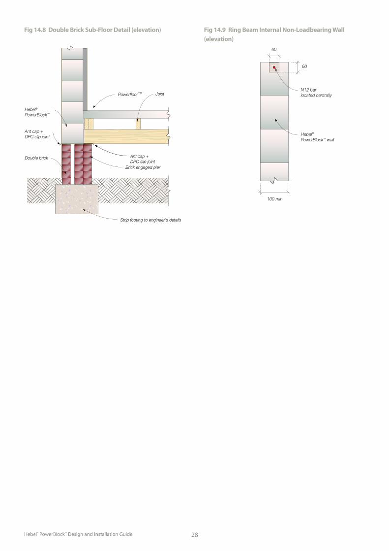
Fig 14.8 Double Brick Sub-Floor Detail (elevation)
Powerfloor™ Joist
Ant cap + DPC slip joint
Brick engaged pier
Strip footing to engineer’s details
Double brick
Ant cap +DPC slip joint
Hebel®
PowerBlock™
60
100 min
60
N12 bar located centrally
Hebel® PowerBlock™ wall
Fig 14.9 Ring Beam Internal Non-Loadbearing Wall (elevation)
Hebel® PowerBlock™ Design and Installation Guide29
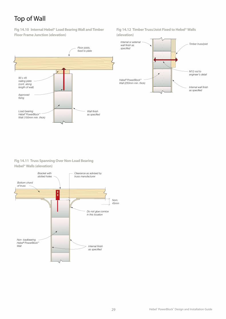
Top of Wall
Fig 14.10 Internal Hebel® Load Bearing Wall and Timber Floor Frame Junction (elevation)
Floor joists,fixed to plate
90 x 45nailing plate(cont. along length of wall)
Load bearingHebel® PowerBlock™
Wall (150mm min. thick)
Approvedfixing
Wall finishas specified
Fig 14.12 Timber Truss/Joist Fixed to Hebel® Walls (elevation)
Fig 14.11 Truss Spanning Over Non-Load Bearing Hebel® Walls (elevation)
Bracket with slotted holes
Bottom chord of truss
Clearance as advised bytruss manufacturer
Do not glue cornicein this location
Internal finishas specified
Non- loadbearingHebel® PowerBlock™ Wall
Nom.45mm
Hebel® PowerBlock™ Wall (250mm min. thick)
Internal or external wall finish as specified
Internal wall finish as specified
Timber truss/joist
M12 rod toengineer’s detail
Hebel® PowerBlock™ Design and Installation Guide 30
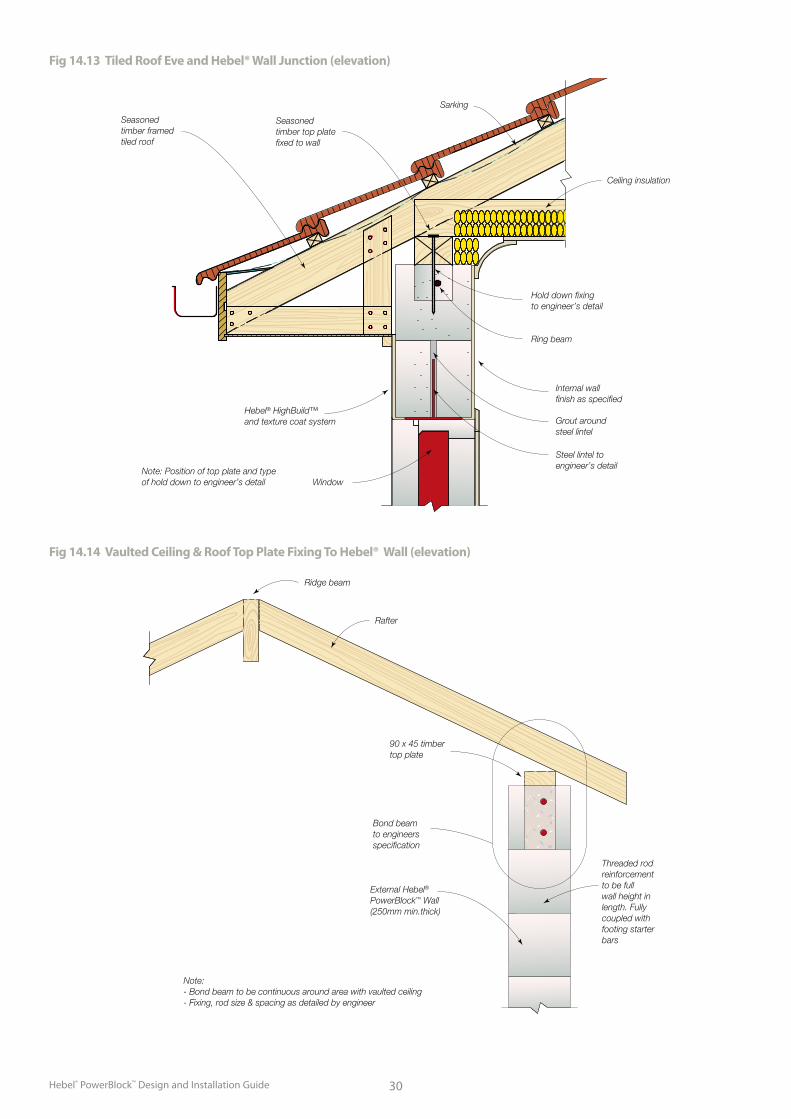
Fig 14.13 Tiled Roof Eve and Hebel® Wall Junction (elevation)
Seasonedtimber framedtiled roof
Seasonedtimber top platefixed to wall
Sarking
Hebel® HighBuild™ and texture coat system
Window
Steel lintel toengineer’s detail
Grout around steel lintel
Internal wallfinish as specified
Ring beam
Hold down fixing to engineer’s detail
Ceiling insulation
Note: Position of top plate and type of hold down to engineer’s detail
Fig 14.14 Vaulted Ceiling & Roof Top Plate Fixing To Hebel® Wall (elevation)
External Hebel®
PowerBlock™ Wall (250mm min.thick)
90 x 45 timber top plate
Bond beam to engineers specification
Rafter
Ridge beam
Threaded rodreinforcementto be full wall height in length. Fully coupled withfooting starterbars
Note: - Bond beam to be continuous around area with vaulted ceiling- Fixing, rod size & spacing as detailed by engineer
Hebel® PowerBlock™ Design and Installation Guide31
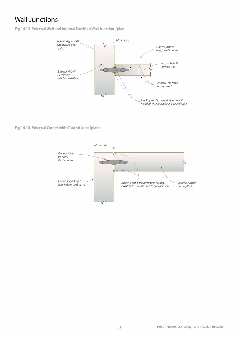
Wall JunctionsFig 14.15 External Wall and Internal Partition Wall Junction (plan)
External Hebel®
PowerBlock™
Wall (250mm thick)
Internal Hebel®
Partition Wall
10mm min.
Control joint tieevery third course
Backing rod & polyurethane sealant,installed to manufacturer’s specification
Internal wall finish as specified
Hebel® Highbuild™and texture coat system
Fig 14.16 External Corner with Control Joint (plan)
External Hebel®
Bracing Wall
Control jointtie every third course
10mm min.
Backing rod & polyurethane sealant, installed to manufacturer’s specification
Hebel® HighBuild™ and texture coat system
Hebel® PowerBlock™ Design and Installation Guide 32
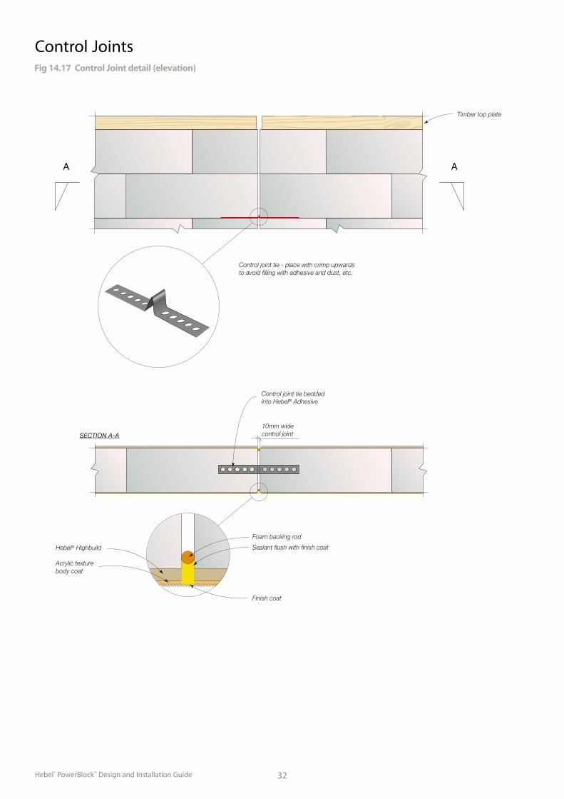
Control JointsFig 14.17 Control Joint detail (elevation)
Foam backing rod
Sealant flush with finish coat
Finish coat
Hebel® Highbuild
Acrylic texturebody coat
Control joint tie - place with crimp upwardsto avoid filling with adhesive and dust, etc.
Timber top plate
SECTION A-A
10mm widecontrol joint
Control joint tie bedded into Hebel® Adhesive
A A
Hebel® PowerBlock™ Design and Installation Guide33
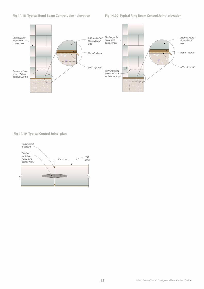
Fig 14.18 Typical Bond Beam Control Joint - elevation Fig 14.20 Typical Ring Beam Control Joint - elevation
Fig 14.19 Typical Control Joint - plan
Control joint tie at every third course max.
Backing rod & sealant
10mm min.Wall lining
Control joints every third course max.
250mm Hebel ® PowerBlock™ wall
Hebel ® Mortar
DPC Slip Joint
Terminate bond beam 200mm embedment typ.
Control joints every third course max.
250mm Hebel ® PowerBlock™
wall
Hebel ® Mortar
DPC Slip Joint
Terminate ring beam 200mm embedment typ.
Hebel® PowerBlock™ Design and Installation Guide 34
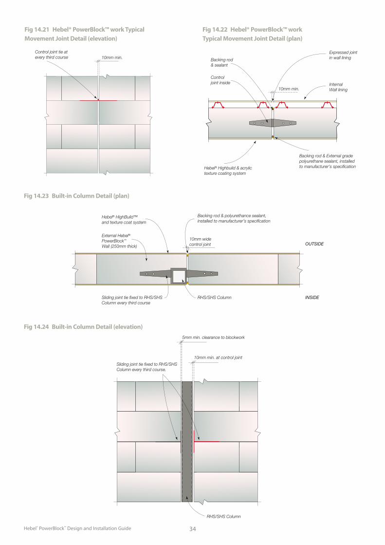
Fig 14.21 Hebel® PowerBlock™ work Typical Movement Joint Detail (elevation)
Fig 14.22 Hebel® PowerBlock™ work Typical Movement Joint Detail (plan)
Control joint tie at every third course 10mm min.
Control joint inside
Backing rod & sealant
10mm min.InternalWall lining
Expressed joint in wall lining
Backing rod & External gradepolyurethane sealant, installed to manufacturer’s specificationHebel® Highbuild & acrylic
texture coating system
Fig 14.23 Built-in Column Detail (plan)
Fig 14.24 Built-in Column Detail (elevation)
10mm widecontrol joint
Hebel® HighBuild™ and texture coat system
External Hebel® PowerBlock™ Wall (250mm thick)
Sliding joint tie fixed to RHS/SHS Column every third course
RHS/SHS Column INSIDE
OUTSIDE
Backing rod & polyurethance sealant, installed to manufacturer’s specification
RHS/SHS Column
Sliding joint tie fixed to RHS/SHS Column every third course.
10mm min. at control joint
5mm min. clearance to blockwork
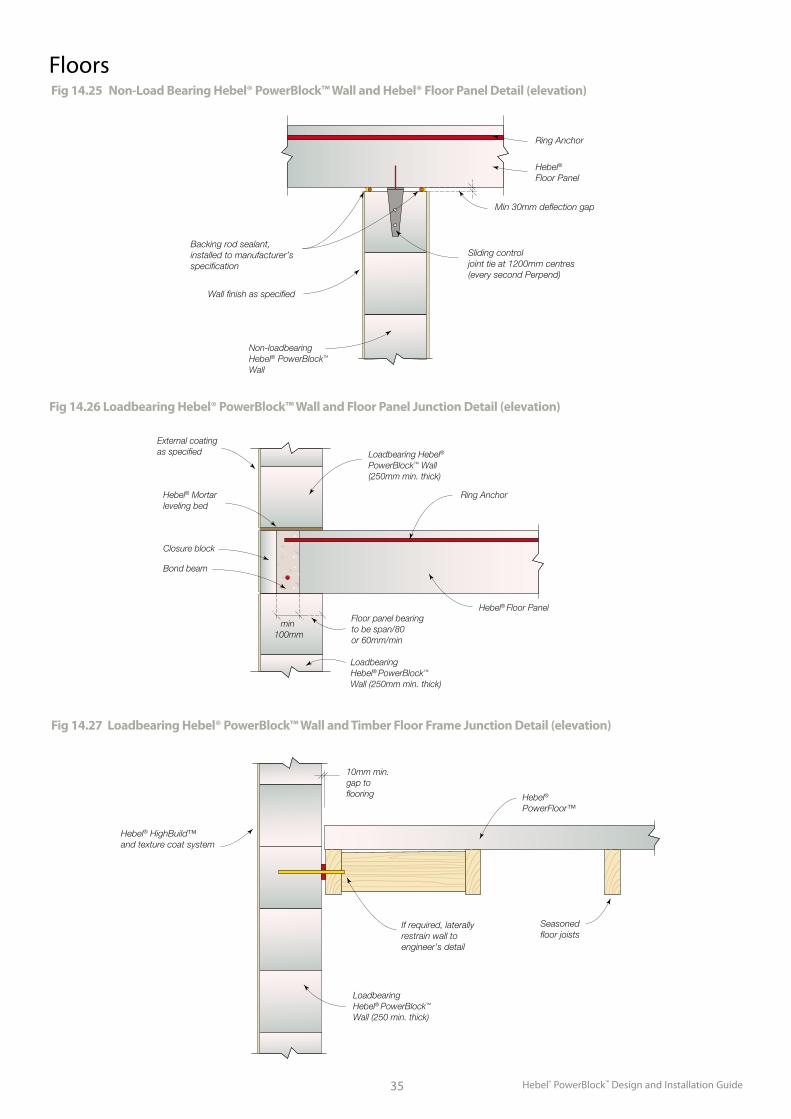
Hebel® PowerBlock™ Design and Installation Guide35
FloorsFig 14.25 Non-Load Bearing Hebel® PowerBlock™ Wall and Hebel® Floor Panel Detail (elevation)
Fig 14.26 Loadbearing Hebel® PowerBlock™ Wall and Floor Panel Junction Detail (elevation)
Fig 14.27 Loadbearing Hebel® PowerBlock™ Wall and Timber Floor Frame Junction Detail (elevation)
Non-loadbearingHebel® PowerBlock™ Wall
Hebel® Floor Panel
Ring Anchor
Sliding controljoint tie at 1200mm centres(every second Perpend)
Backing rod sealant, installed to manufacturer’s specification
Wall finish as specified
Min 30mm deflection gap
Ring Anchor
Loadbearing Hebel®
PowerBlock™ Wall(250mm min. thick)
Note: Where the floor system is considered a diaphragm, the engineer shalldetermine if the ring anchor reinforcement size and anchorage is adequate.
Hebel® Floor Panel
Loadbearing Hebel® PowerBlock™ Wall (250mm min. thick)
Hebel® Mortarleveling bed
Closure block
Bond beam
min 100mm
Floor panel bearing to be span/80 or 60mm/min
External coatingas specified
LoadbearingHebel® PowerBlock™ Wall (250 min. thick)
10mm min.gap to flooring
If required, laterally restrain wall to engineer’s detail
Seasonedfloor joists
Hebel®
PowerFloor™
Hebel® HighBuild™ and texture coat system
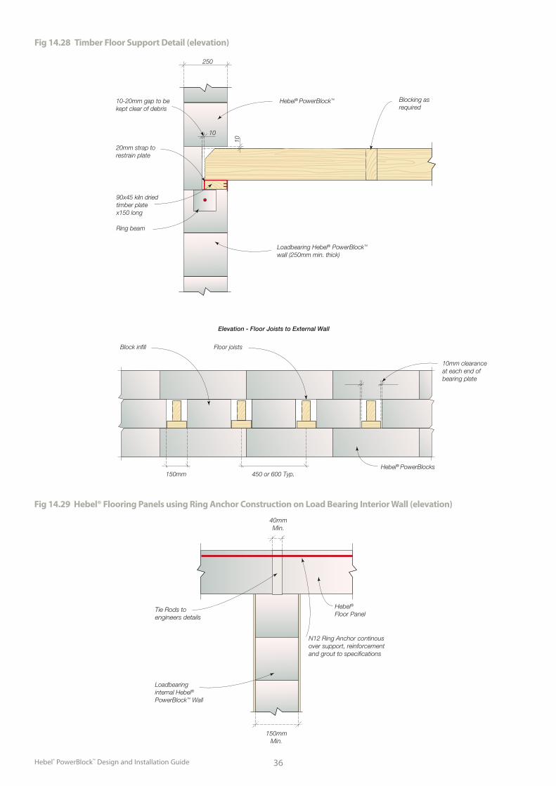
Hebel® PowerBlock™ Design and Installation Guide 36
Fig 14.28 Timber Floor Support Detail (elevation)
10
10
250
Loadbearing Hebel® PowerBlock™ wall (250mm min. thick)
Blocking as required
Hebel® PowerBlock™10-20mm gap to be kept clear of debris
20mm strap to restrain plate
90x45 kiln dried timber plate x150 long
Ring beam
Elevation - Floor Joists to External Wall
Floor joists
150mm 450 or 600 Typ.
Block infill
Hebel® PowerBlocks
10mm clearance at each end of bearing plate
Fig 14.29 Hebel® Flooring Panels using Ring Anchor Construction on Load Bearing Interior Wall (elevation)
Loadbearing internal Hebel®
PowerBlock™ Wall
Hebel® Floor Panel
40mmMin.
150mmMin.
N12 Ring Anchor continous over support, reinforcement and grout to specifications
Tie Rods to engineers details
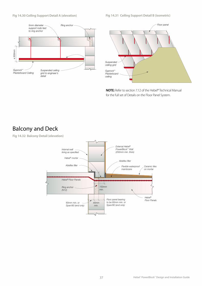
Hebel® PowerBlock™ Design and Installation Guide37
≤ 30
0mm
5mm diameter support rods tied to ring anchor
Ring anchor
Gyprock™ Plasterboard Ceiling
Suspended ceiling grid to engineer’s detail
Floor panel
Gyprock™ Plasterboard ceiling
Suspended ceiling grid
Fig 14.30 Ceiling Support Detail A (elevation) Fig 14.31 Ceiling Support Detail B (isometric)
NOTE: Refer to section 7.12 of the Hebel® Technical Manual for the full set of Details on the Floor Panel System.
Fig 14.32 Balcony Detail (elevation)
External Hebel®
PowerBlock™ Wall(250mm min. thick)
Ableflex filler
Ableflex filler Flexible waterproof mambrane
Ceramic tiles on mortar
Hebel®
Floor Panels
Internal wall lining as specified
Hebel® mortar
Ring anchor(N12)
40mmmin.
150mm min.
60mm min. or Span/80 (end only)
Floor panel bearing to be 60mm min. or Span/80 (end only)
Hebel® Floor Panels
Balcony and Deck
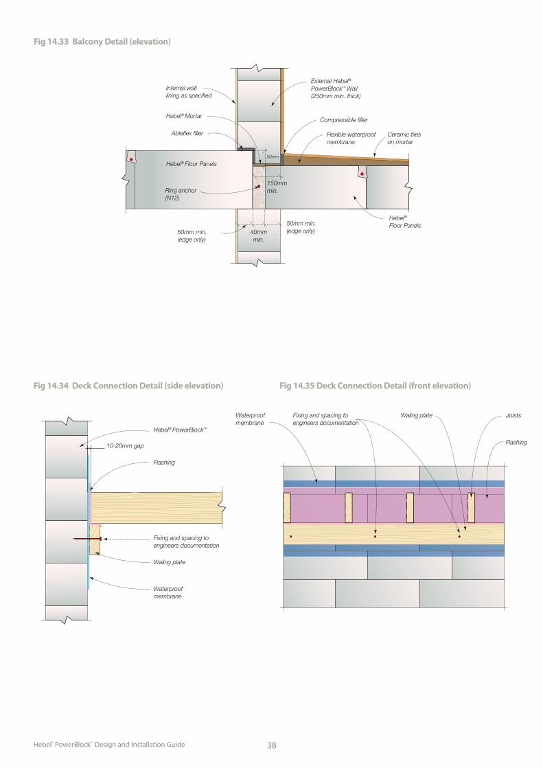
Hebel® PowerBlock™ Design and Installation Guide 38
Fig 14.33 Balcony Detail (elevation)
External Hebel®
PowerBlock™ Wall(250mm min. thick)
Compressible filler
Flexible waterproof membrane
Ceramic tiles on mortar
Hebel®
Floor Panels
Internal wall lining as specified
Hebel® Mortar
Ring anchor(N12)
40mmmin.
50mm
50mm min. (edge only)
50mm min.(edge only)
Hebel® Floor Panels
150mm min.
Ableflex filler
Fig 14.34 Deck Connection Detail (side elevation) Fig 14.35 Deck Connection Detail (front elevation)
Flashing
10-20mm gap
Waling plate
Fixing and spacing to engineers documentation
Waterproofmembrane
Hebel® PowerBlock™
Waterproofmembrane
Fixing and spacing to engineers documentation
JoistsWaling plate
Flashing
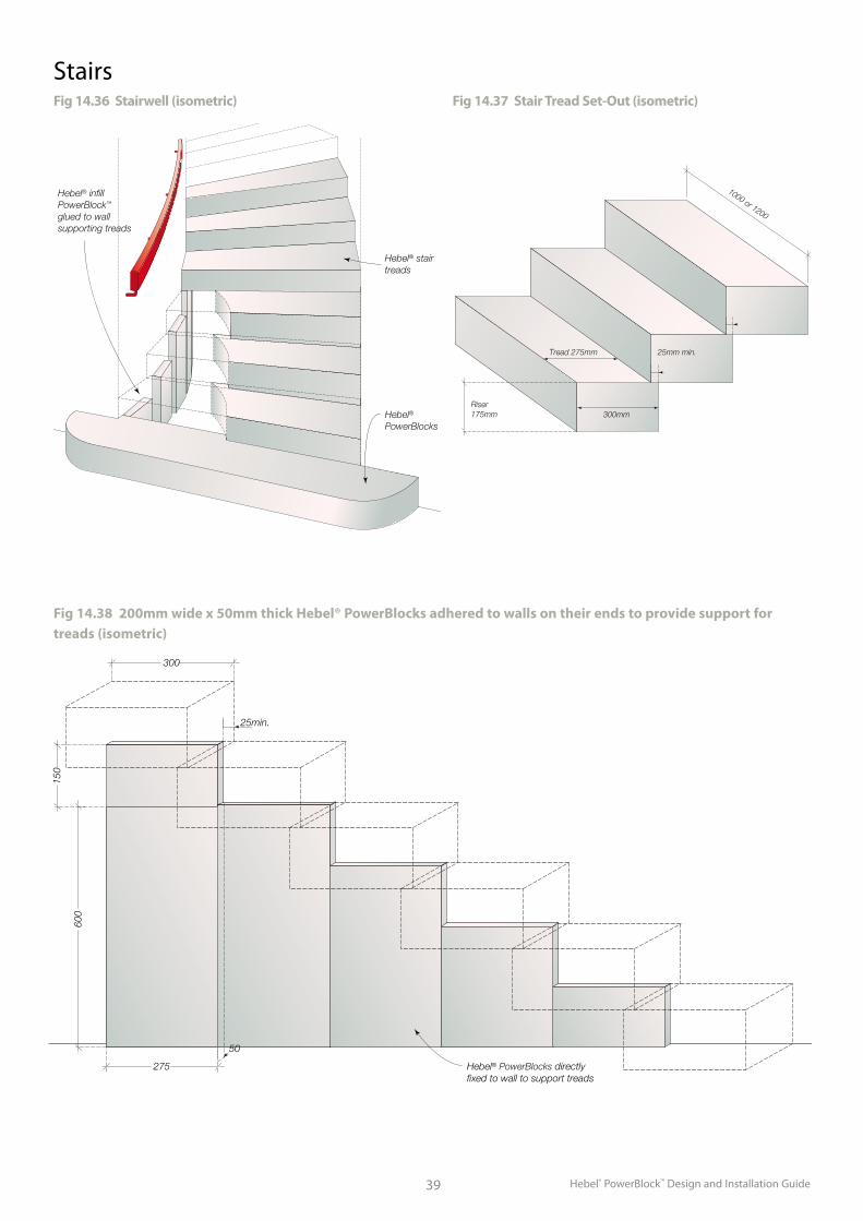
Hebel® PowerBlock™ Design and Installation Guide39
Tread 275mm 25mm min.
300mmRiser175mm
1000 or 1200
Hebel® infill PowerBlock™ glued to wall supporting treads
Hebel® stair treads
Hebel® PowerBlocks
Fig 14.36 Stairwell (isometric) Fig 14.37 Stair Tread Set-Out (isometric)
150
275 Hebel® PowerBlocks directly fixed to wall to support treads
300
600
50
25min.
Fig 14.38 200mm wide x 50mm thick Hebel® PowerBlocks adhered to walls on their ends to provide support for treads (isometric)
Stairs
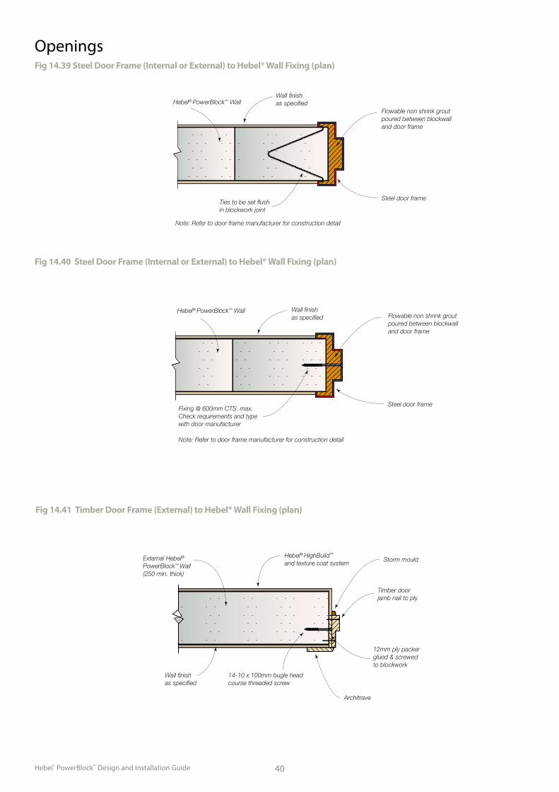
Hebel® PowerBlock™ Design and Installation Guide 40
OpeningsFig 14.39 Steel Door Frame (Internal or External) to Hebel® Wall Fixing (plan)
Wall finishas specified
Ties to be set flushin blockwork joint
Flowable non shrink grout poured between blockwalland door frame
Steel door frame
Note: Refer to door frame manufacturer for construction detail
Hebel® PowerBlock™ Wall
Fig 14.40 Steel Door Frame (Internal or External) to Hebel® Wall Fixing (plan)
Hebel® PowerBlock™ Wall Wall finishas specified Flowable non shrink grout
poured between blockwalland door frame
Fixing @ 600mm CTS. max.Check requirements and typewith door manufacturer
Steel door frame
Note: Refer to door frame manufacturer for construction detail
Fig 14.41 Timber Door Frame (External) to Hebel® Wall Fixing (plan)
External Hebel®
PowerBlock™ Wall(250 min. thick)
Hebel® HighBuild™
and texture coat system Storm mould
Timber doorjamb nail to ply
12mm ply packerglued & screwed to blockwork
14-10 x 100mm bugle headcourse threaded screw
Wall finish as specified
Architrave
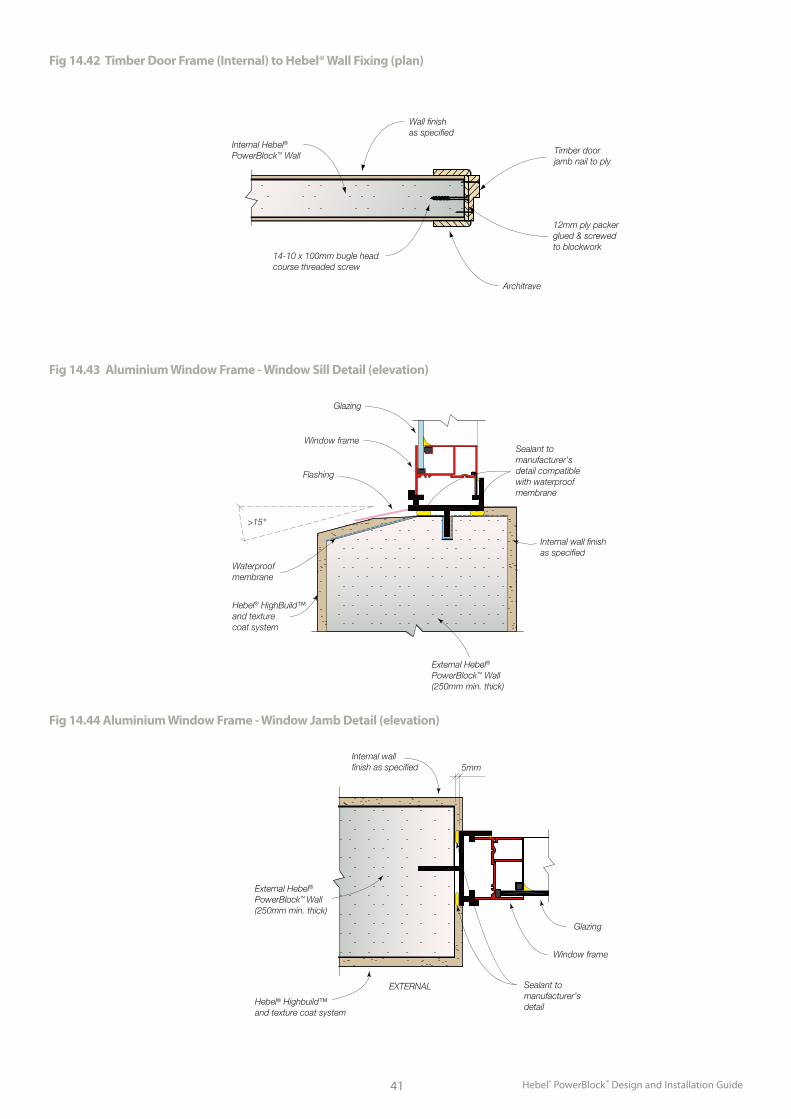
Hebel® PowerBlock™ Design and Installation Guide41
Fig 14.42 Timber Door Frame (Internal) to Hebel® Wall Fixing (plan)
Internal Hebel®
PowerBlock™ Wall
Wall finishas specified
Timber doorjamb nail to ply
12mm ply packerglued & screwed to blockwork
14-10 x 100mm bugle headcourse threaded screw
Architrave
Fig 14.43 Aluminium Window Frame - Window Sill Detail (elevation)
Fig 14.44 Aluminium Window Frame - Window Jamb Detail (elevation)
External Hebel®
PowerBlock™ Wall (250mm min. thick)
>15°
Waterproofmembrane
Hebel® HighBuild™ and texture coat system
Glazing
Window frame
Flashing
Sealant to manufacturer’sdetail compatiblewith waterproofmembrane
Internal wall finish as specified
External Hebel®
PowerBlock™ Wall(250mm min. thick)
5mm
Glazing
Window frame
Sealant to manufacturer’s detailHebel® Highbuild™
and texture coat system
Internal wall finish as specified
EXTERNAL
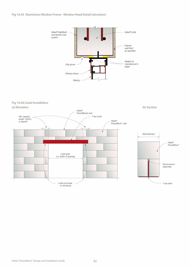
Hebel® PowerBlock™ Design and Installation Guide 42
Min. bearinglength 150mm or span/8
T-bar Lintel
Hebel®
PowerBlock™ wall
Wall thickness
T-bar lintel
Grout around steel lintel
Hebel® PowerBlocks over
Hebel® PowerBlock™
Lintel span (i.e. width of opening)
Lintel must bear on full blocks
Fig 14.46 Lintel Installation (a) Elevation (b) Section
Fig 14.45 Aluminium Window Frame - Window Head Detail (elevation)
Hebel® Lintel
Internal wall finish as specified
Hebel® HighBuild and texture coat system
Glazing
Window frame
Drip groveSealant to manufacturer’s detail
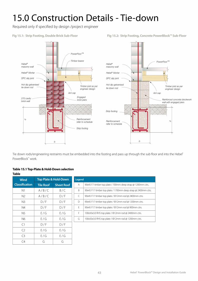
Hebel® PowerBlock™ Design and Installation Guide43
Fig 15.1: Strip Footing, Double Brick Sub-Floor Fig 15.2: Strip Footing, Concrete PowerBlock™ Sub-Floor
270 CAVITY BRICK WALL
110 BRICK WALL WITH 230x230 ENGAGED BRICK PIERSSTRIP
FOOTING
ANT CAP
TIMBER JOIST AS PER ENGINEER DESIGN
TIMBER BEARER
POWER FLOOR
HEBEL MASONRY
WALL
SCALE = 1:20DOUBLE BRICK SUB-FLOOR
HOT DIP GALVANISED TIE
DOWN ROD
CORE-FILLED CONCRETE BLOCKWORK WALL WITH ENGAGED PIERS
STRIP FOOTING
HEBEL MASONRY
WALL
SCALE = 1:20CONCRETE BLOCK SUB-FLOOR
HOT DIP GALVANISED TIE
DOWN ROD
DPC SLIP JOINTDPC SLIP
JOINT
TIMBER JOIST AS PER ENGINEER DESIGNPOWER FLOOR
d
b
d
b
REINFORCEMENT REFER TO SCHEDULE
REINFORCEMENT REFER TO SCHEDULE
ANT CAP
HEBEL MORTARHEBEL
MORTAR
HOT DIP GALVANISED TIE
DOWN ROD
Powerfloor™ Joist
Ant cap + DPC
Brick engaged pier
Tie down rod
Strip footing to engineer’s details
Double brick
DPC Slip joint
Hebel® Blocks
PowerFloor™Hebel®
masonry wall
Hebel® Mortar
DPC slip joint
Hot dip galvanised
tie down rod
Reinforcement refer to schedule
Reinforced concrete blockwork wall with engaged piers
Ant cap
b
d
Strip footing
Timber joist as perengineer design
PowerFloor™
Timber bearerHebel®
masonry wall
Hebel® Mortar
DPC slip joint
Hot dip galvanised tie down rod
270 cavity brick wall
Reinforcement refer to schedule
Engaged brick piers
Ant cap
Strip footing
Timber joist as perengineer design
b
d
15.0 Construction Details - Tie-down
Tie down rods/engineering restraints must be embedded into the footing and pass up through the sub floor and into the Hebel® PowerBlock™ work.
Required only if specified by design /project engineer
Table 15.1 Top-Plate & Hold-Down selection Table
Wind Classification
Top Plate & Hold-Down
Tile Roof Sheet Roof
N1 A / B / C B / C
N2 A / B / C D / F
N3 D / F D / F
N4 D / F D / F
N5 E / G E / G
N6 E / G E / G
C1 D / F D / F
C2 E / G E / G
C3 E / G E / G
C4 G G
Legend
A 90x45 F7 timber top plate / 700mm deep strap @ 1200mm ctrs.
B 90x45 F17 timber top plate / 1700mm deep strap @ 2400mm ctrs.
C 90x45 F17 timber top plate / Ф12mm rod @ 2400mm ctrs.
D 90x45 F17 timber top plate / Ф12mm rod @ 1200mm ctrs.
E 90x45 F17 timber top plate / Ф12mm rod @ 900mm ctrs.
F 100x50x3.0 RHS top plate / Ф12mm rod @ 2400mm ctrs.
G 100x50x3.0 RHS top plate / Ф12mm rod @ 1200mm ctrs.
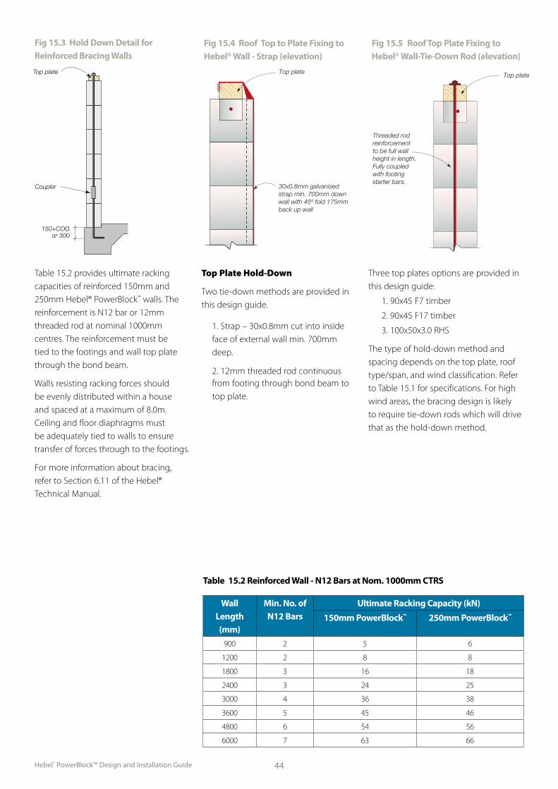
Hebel® PowerBlock™ Design and Installation Guide 44
Table 15.2 provides ultimate racking capacities of reinforced 150mm and 250mm Hebel® PowerBlock™ walls. The reinforcement is N12 bar or 12mm threaded rod at nominal 1000mm centres. The reinforcement must be tied to the footings and wall top plate through the bond beam.
Walls resisting racking forces should be evenly distributed within a house and spaced at a maximum of 8.0m. Ceiling and floor diaphragms must be adequately tied to walls to ensure transfer of forces through to the footings.
For more information about bracing, refer to Section 6.11 of the Hebel® Technical Manual.
Top Plate Hold-Down
Two tie-down methods are provided in this design guide.
1. Strap – 30x0.8mm cut into inside face of external wall min. 700mm deep.
2. 12mm threaded rod continuous from footing through bond beam to top plate.
Three top plates options are provided in this design guide:
1. 90x45 F7 timber
2. 90x45 F17 timber
3. 100x50x3.0 RHS
The type of hold-down method and spacing depends on the top plate, roof type/span, and wind classification. Refer to Table 15.1 for specifications. For high wind areas, the bracing design is likely to require tie-down rods which will drive that as the hold-down method.
Coupler
150+COG or 300
Top plate
Fig 15.3 Hold Down Detail for Reinforced Bracing Walls
Fig 15.4 Roof Top to Plate Fixing to Hebel® Wall - Strap (elevation)
Top plate
30x0.8mm galvanised strap min. 700mm down wall with 45º fold 175mm back up wall
Fig 15.5 Roof Top Plate Fixing to Hebel® Wall-Tie-Down Rod (elevation)
Threaded rodreinforcementto be full wallheight in length.Fully coupled with footingstarter bars.
Top plate
Table 15.2 Reinforced Wall - N12 Bars at Nom. 1000mm CTRS
Wall Length (mm)
Min. No. of N12 Bars
Ultimate Racking Capacity (kN)
150mm PowerBlock™ 250mm PowerBlock™
900 2 5 6
1200 2 8 8
1800 3 16 18
2400 3 24 25
3000 4 36 38
3600 5 45 46
4800 6 54 56
6000 7 63 66
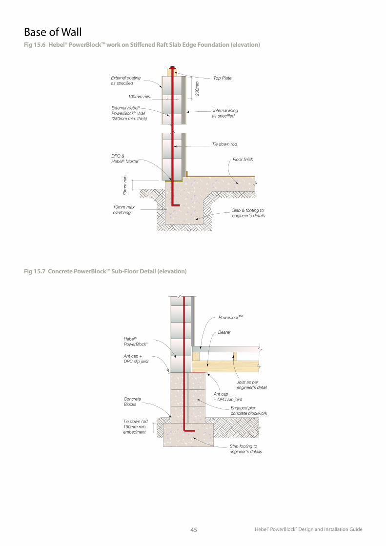
Hebel® PowerBlock™ Design and Installation Guide45
Fig 15.6 Hebel® PowerBlock™ work on Stiffened Raft Slab Edge Foundation (elevation)
Internal liningas specified
Tie down rod
Top Plate
Floor finish
Slab & footing toengineer’s details
10mm max.overhang
DPC & Hebel® Mortar
75m
m m
in.
External Hebel®
PowerBlock™ Wall(250mm min. thick)
External coating as specified
100mm min. 200m
m
Base of Wall
Fig 15.7 Concrete PowerBlock™ Sub-Floor Detail (elevation)
Powerfloor™
Hebel®
PowerBlock™
Ant cap +DPC slip joint
ConcreteBlocks
Engaged pierconcrete blockwork
Bearer
Ant cap + DPC slip joint
Strip footing to engineer’s details
Tie down rod150mm min.embedment
Joist as perengineer’s detail
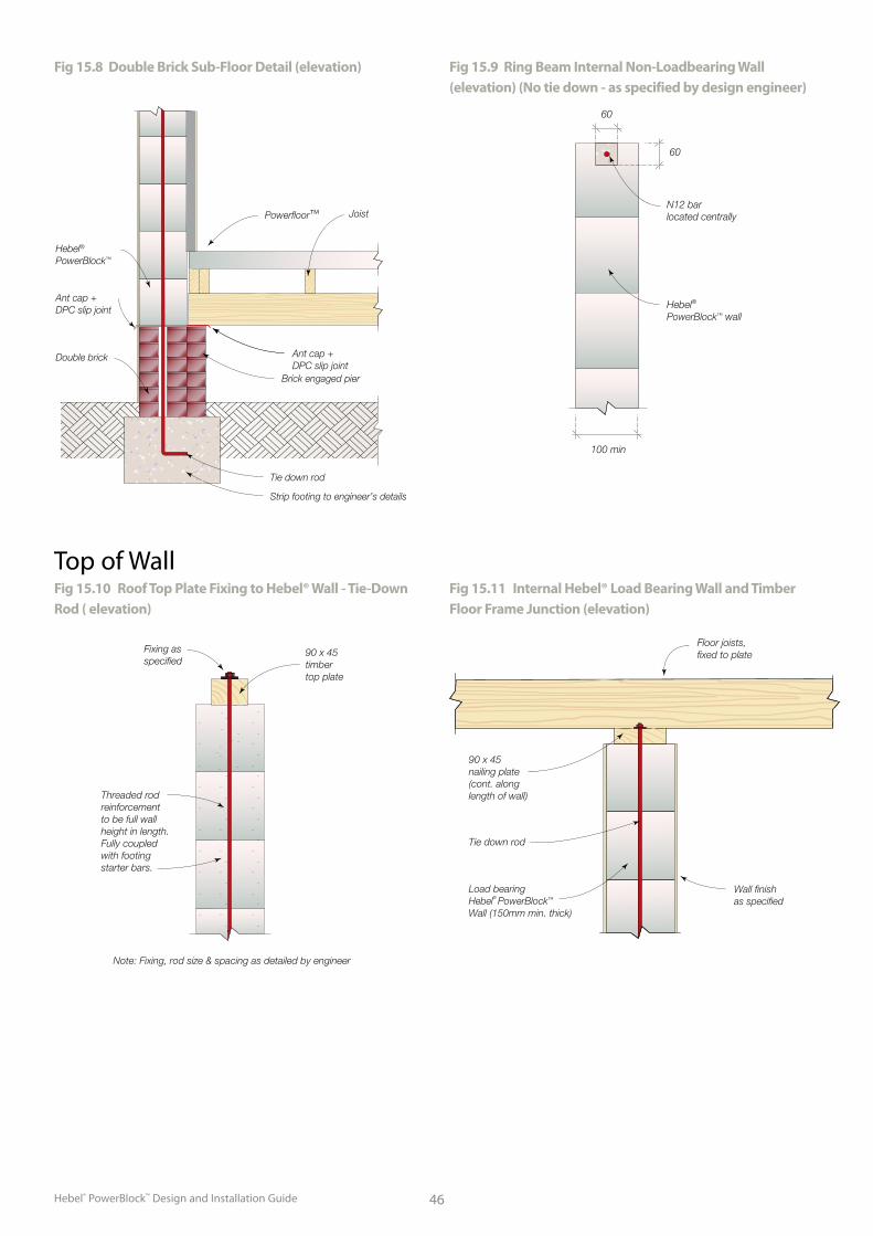
Hebel® PowerBlock™ Design and Installation Guide 46
Fig 15.8 Double Brick Sub-Floor Detail (elevation)
Powerfloor™ Joist
Ant cap + DPC slip joint
Brick engaged pier
Tie down rod
Strip footing to engineer’s details
Double brick
Ant cap +DPC slip joint
Hebel®
PowerBlock™
60
100 min
60
N12 bar located centrally
Hebel® PowerBlock™ wall
Fig 15.9 Ring Beam Internal Non-Loadbearing Wall (elevation) (No tie down - as specified by design engineer)
Top of WallFig 15.10 Roof Top Plate Fixing to Hebel® Wall - Tie-Down Rod ( elevation)
Fixing asspecified
Threaded rodreinforcementto be full wallheight in length.Fully coupled with footingstarter bars.
Note: Fixing, rod size & spacing as detailed by engineer
90 x 45 timbertop plate
Fig 15.11 Internal Hebel® Load Bearing Wall and Timber Floor Frame Junction (elevation)
Floor joists,fixed to plate
90 x 45nailing plate(cont. along length of wall)
Load bearingHebel® PowerBlock™
Wall (150mm min. thick)
Tie down rod
Wall finishas specified
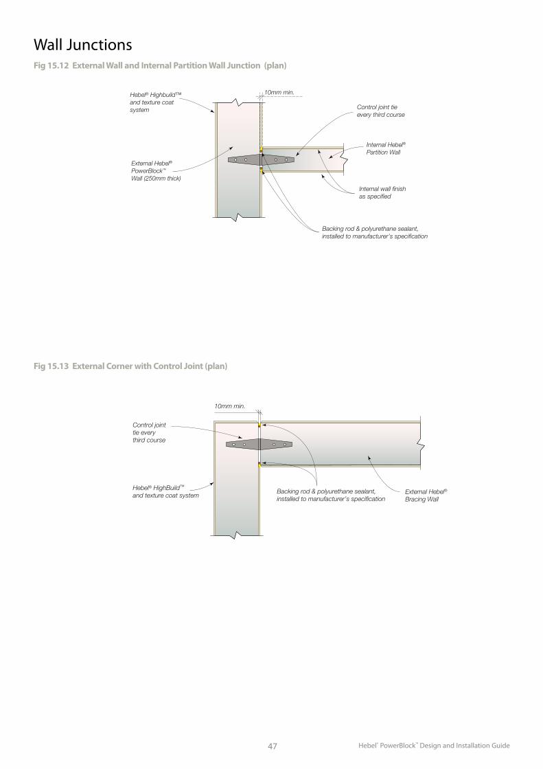
Hebel® PowerBlock™ Design and Installation Guide47
Wall JunctionsFig 15.12 External Wall and Internal Partition Wall Junction (plan)
External Hebel®
PowerBlock™
Wall (250mm thick)
Internal Hebel®
Partition Wall
10mm min.
Control joint tieevery third course
Backing rod & polyurethane sealant,installed to manufacturer’s specification
Internal wall finish as specified
Hebel® Highbuild™and texture coat system
Fig 15.13 External Corner with Control Joint (plan)
External Hebel®
Bracing Wall
Control jointtie every third course
10mm min.
Backing rod & polyurethane sealant, installed to manufacturer’s specification
Hebel® HighBuild™ and texture coat system
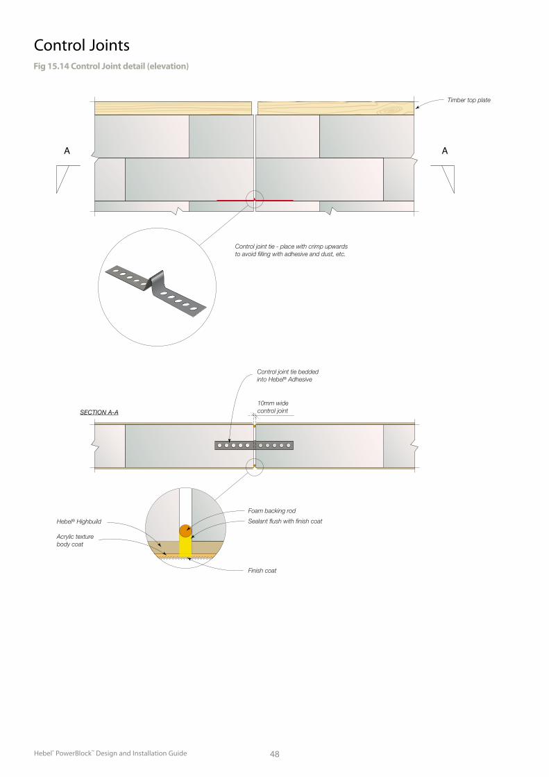
Hebel® PowerBlock™ Design and Installation Guide 48
Control JointsFig 15.14 Control Joint detail (elevation)
Foam backing rod
Sealant flush with finish coat
Finish coat
Hebel® Highbuild
Acrylic texturebody coat
Control joint tie - place with crimp upwardsto avoid filling with adhesive and dust, etc.
Timber top plate
SECTION A-A
10mm widecontrol joint
Control joint tie bedded into Hebel® Adhesive
A A
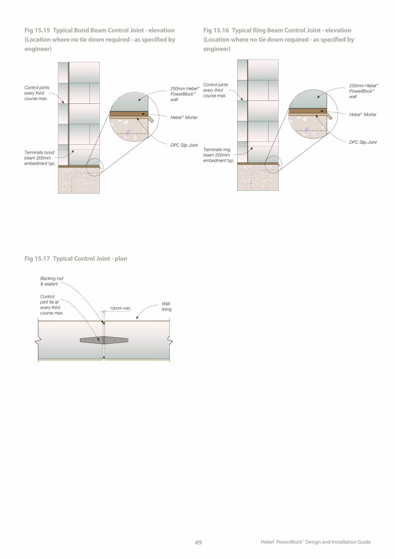
Hebel® PowerBlock™ Design and Installation Guide49
Fig 15.15 Typical Bond Beam Control Joint - elevation (Location where no tie down required - as specified by engineer)
Fig 15.16 Typical Ring Beam Control Joint - elevation (Location where no tie down required - as specified by engineer)
Fig 15.17 Typical Control Joint - plan
Control joint tie at every third course max.
Backing rod & sealant
10mm min.Wall lining
Control joints every third course max.
250mm Hebel ® PowerBlock™ wall
Hebel ® Mortar
DPC Slip Joint
Terminate bond beam 200mm embedment typ.
Control joints every third course max.
250mm Hebel ® PowerBlock™
wall
Hebel ® Mortar
DPC Slip Joint
Terminate ring beam 200mm embedment typ.
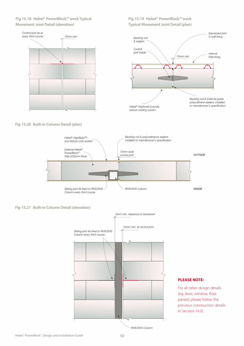
Hebel® PowerBlock™ Design and Installation Guide 50
Fig 15.18 Hebel® PowerBlock™ work Typical Movement Joint Detail (elevation)
Fig 15.19 Hebel® PowerBlock™ work Typical Movement Joint Detail (plan)
Control joint tie at every third course 10mm min.
Control joint inside
Backing rod & sealant
10mm min.InternalWall lining
Expressed joint in wall lining
Backing rod & External gradepolyurethane sealant, installed to manufacturer’s specificationHebel® Highbuild & acrylic
texture coating system
Fig 15.20 Built-in Column Detail (plan)
Fig 15.21 Built-in Column Detail (elevation)
10mm widecontrol joint
Hebel® HighBuild™ and texture coat system
External Hebel® PowerBlock™ Wall (250mm thick)
Sliding joint tie fixed to RHS/SHS Column every third course
RHS/SHS Column INSIDE
OUTSIDE
Backing rod & polyurethance sealant, installed to manufacturer’s specification
RHS/SHS Column
Sliding joint tie fixed to RHS/SHS Column every third course.
10mm min. at control joint
5mm min. clearance to blockwork
PLEASE NOTE:
For all other design details (eg. door, window, floor panels) please follow the previous construction details in Section 14.0)

Hebel® PowerBlock™ Design and Installation Guide51
Appendix A - Carpet Installation
Panel Surface PreparationSweep the floor surface to remove
debris and loose particles. Expose
all surface blemishes such as chips,
cracks, gaps, ridges or the like. Fill
all unacceptable locations with an
appropriate and compatible patching
compound such as Hebel® Patch or
levelling compound as required.
Ensure panels are then dry.
Carpet Smooth Edge InstallationInstallation of Carpet Smooth Edge
(Gripper) is to be in accordance with
AS/NZS 2455.1:1995.
Installation of carpet gripper prior
to laying carpet requires the use of
specifically selected nails or course
threaded screws. Standard fixings
supplied with the carpet gripper
are not suitable for fixing to Hebel®
PowerFloor™ panels. Carpet gripper
strips are available without factory
supplied nails. For carpet gripper
installation near the panel edge, only
glue is recommended. If relying on glue
only, the carpet can not be stretched
until the glue is set after approximately
24 hours.
Underlay InstallationMinimum medium duty underlay is to
be used. No other special requirements.
Carpet InstallationAs per carpet manufacturer's guidelines.
No other special requirements.
Fixing Type Description Application Method Installation Notes
Twist Nails 51mm dome head twist nail
Coil Nail Gun (Refer to Fig A.1)
The head of the twist nail should finish flush with the surface of the gripper strip
Screws Type 17 point - course thread No. 8g x 50mm - Countersinking screw
Makita 6834Auto Feed Screwdriver (Refer to Fig A.2)
The head of the twist nail should finish flush with the surface of the carpet gripper strip
Screws Type 17 point-Trimhead deck Screw. 4.2 x 50mm 4.2 x 65mm
Quickdrive auto feed The head of the screw should be flush with the smooth edge
Fig A.2Fig A.1
Table A.1 - Carpet Smooth Edge Fixings
HELIT043 October 2015
Available from:
The better way to buildHebel is a quality building product, and is backed by CSR Building Products Limited.
For more information visit our website.
www.hebel.com.auFor sales enquiries or further information, please telephone us from anywhere in Australia:
1300 369 448
Hebel® is a registered trademark of the Xella group. CSR Building Products Ltd is an exclusive licensee of Xella. CSR Hebel is a business of CSR Building Products Ltd ABN 55 008 631 356.
CSR, PowerPanel®, PowerClad®, Hebel Block®, PowerFloor®, Hebel Floor®, PowerFence®, HighBuild®, are registered trademarks of CSR Building Products Limited.
CSR HEBELTriniti 3, 39 Delhi RoadNorth Ryde NSW 2113, AustraliaTelephone +61 2 9235 8000
Health and safetyInformation on any known health risks of our products and how to handle them safely is on product packaging and / or the accompanying documentation.
Additional information is listed in the Material Safety Data Sheet (MSDS). To obtain a copy of a MSDS, download from www.hebel.com.au. Contractors are required by law to perform their own risk assessments before undertaking work.
Performance and certification
Hebel® products and systems are developed in Australia by CSR Building Products. ABN. 55 008 631 356. It is a manufacturer and supplier of Hebel Autoclaved Aerated Concrete (AAC) products. Because it is a manufacturer and supplier only, CSR does not employ people qualified as Accredited or Principal Certifiers.
CSR is therefore unable to provide Construction Compliance Certificates or Statements of Compliance. CSR conducts appropriate testing of its products and systems to determine performance levels. These include structural, fire and acoustic tests. Testing is conducted and certified by appropriate specialists in these fields. When using Hebel products and systems in specific projects, such specialists should be consulted to ensure compliance with the Building Code of Australia and relevant Australian Standards.
DisclaimerInformation presented in this document is supplied in good faith and to the best of our knowledge was accurate at the time of preparation. The provision of this information should not be construed as a recommendation to use any of our products in violation of any patent rights or in breach of any statute or regulation. Users are advised to make their own determination as to the suitability of this information in relation to their particular purpose or specific circumstances. Since the information contained in this document may be applied under conditions beyond our control, no responsibility can be accepted by CSR ‚ or its staff for any loss or damage caused by any person acting or refraining from action as a result of misuse of this information.
Other
The design of a wall, floor or fence system requires the services of professional consultants. This document has been prepared as a source of information to provide general guidance to those consultants – and in no way replaces the services of the professional consultant and relevant engineers designing the project.
No liability can therefore be accepted by CSR or other parties for the use of this document. Hebel products and systems undergo constant research and development to integrate new technology and reflect ongoing performance enhancement.
Hebel systems are constantly reviewed so as to reflect any changes in legislative building requirements and or general developments in common building practice, due to our commitment to continual development and improving our building systems.
We advise that all users of this document should regularly check that this document is current, and they are applying our latest design information.
The latest editions of our documents are available on our website: www.hebel.com.au