Embed Size (px)
Citation preview
Date of Issuance: January 1, 2014
DESIGN GUIDELINES
AND
TECHNICAL STANDARDS

NORTHWESTERN UNIVERSITY Technical Standards Issuance Date: 01.01.2014
ELECTRICAL DESIGN CRITERIA 26 0000 - 1
DIVISION 26 – ELECTRICAL
SECTION 26 0000 – ELECTRICAL DESIGN CRITERIA
General Design Criteria
1. General: The Electrical systems within Northwestern’s facilities need to be designed and maintained to meet the goals of safe, reliable and efficient operation.
2. Safety: Electrical safety is paramount in any facility and that begins with a design that is safe to operate and maintain. Electrical equipment should be specified and located with emphasis placed on reduced maintenance exposure, manageable short circuit and ground fault current, and arc-flash safety.
3. Reliability: Reliability in the electrical system is also critical to meeting the goals of the University to provide world class technical and health research capabilities. Electrical systems that are reliable also require less maintenance, have lower operating costs, and produce less waste.
4. Redundancy: The design must identify and address points of failure for systems serving critical spaces, which are to be identified with the owner. Redundancy and/or back-up systems should be identified.
5. Sustainability: Electrical system design should address sustainable design concepts, energy use reduction, and occupant comfort to meet the goals of NU and the community it serves.
Sustainability Overview
1. Sustainability is not just about energy efficiency and energy savings. From the Advanced Lighting Guidelines: “Lighting is primarily provided for people, not for the buildings or roadways or objects illuminated. Peoples’ needs should determine what kind of lighting is provided. Meeting those needs is important because a good visual environment is critical to health, productivity, comfort, aesthetics, safety, communication and mood. Lighting designers have an opportunity and responsibility to support and improve the quality of life for everyone. Recently, lighting has become a subject of much greater interest than for many years. This is for three reasons:
a. The ageing of the population in many developed countries. As the human visual system ages, its capabilities deteriorate. Lighting can be used to help older people to see well and hence to live active lives for longer.
b. The need to reduce carbon emissions to minimize climate change. Lighting is a major user of electricity and the generation of electricity is a major source of carbon emissions. This means that lighting is under pressure to do more with less.
c. The recognition that exposure to light can have significant non-visual effects on human health. The potential for exposure to light to cause tissue damage has been known for many years, but now its influence on the human circadian
NORTHWESTERN UNIVERSITY Technical Standards Issuance Date: 01.01.2014
ELECTRICAL DESIGN CRITERIA 26 0000 - 2
system, which operates at a very basic level of human physiology, is also appreciated.
d. Taken together, these developments mean that the number of factors that should be considered when determining if a lighting installation is fit for purpose has increased. However, one factor that will almost always need to be considered is how well the lighting enables people to see.”
2. Lighting energy efficiency shall be a significant consideration for all lighting designs. The following shall be taken into consideration:
a. Efficiency based on ASHRAE 90.1 guidelines – strive to improve efficiency relative to the guidelines while maintaining lighting quality
b. IESNA guidelines based on the latest IESNA Lighting Handbook
3. Site lighting shall be designed to reduce night sky light pollution.
4. Motor efficiency – motors shall be premium efficiency.
Utility Service Entrance
1. Service entrance types vary depending on campus location, building size and type of use.
a. Transformer Vaults:
i. Underground or indoor transformer vaults are preferred over above ground, outdoor vaults or pad-mounted transformers for aesthetics, reliability and maintenance. Undergound vaults are to be adjacent to the building they serve.
ii. Utility (ComEd)-owned transformer vaults are to be built to ComEd standards for size and construction. Transformer vaults are required to be ventilated to ComEd standards based on the transformer and equipment ratings within the vault.
iii. University-owned transformer vaults are to be located to allow maintenance and removal of failed transformers or other vault equipment. Indoor vaults are to be constructed with a three-hour fire rating.
iv. Natural ventilation of the vault is preferred over forced ventilation. A minimum of two square inches of open space per transformer rated kVA is required for natural ventilation. Two CFM of forced ventilation per transformer rated kVA is required for forced ventilation. Forced ventilated vaults require high temperature and fan failure alarms connected to the Building Automation System (BAS).
v. Vault equipment must be clearly marked, so that each component and raceway can be identified from the entrance to the vault.
NORTHWESTERN UNIVERSITY Technical Standards Issuance Date: 01.01.2014
ELECTRICAL DESIGN CRITERIA 26 0000 - 3
vi. Vaults are to be lighted with low maintenance, all-weather lighting fixtures connected to the building essential power system and switched at the entrance. Adequate lighting is to be provided to allow identification of all component and raceway markings from the entrance to the vault.
vii. Vault man doors are to open in the direction of egress with panic hardware.
viii. Vault equipment doors are to be sized to allow the largest single piece of equipment to be removed for replacement.
ix. A 6-inch concrete dike is to be cast onto the floor to prevent leaking transformer oil from escaping vault. An integral transformer leak basin can be used in lieu of a dike. The basin is to be sized large enough to contain the liquid contents of the transformer.
x. A sump pit with cover is to be placed in one corner of vaults located below or at grade.
xi. Where allowed by the AHJ, water fire suppression is not to be used in transformer vaults.
xii. For transformer vaults and/or main distribution rooms located below grade, provide high water alarms connected to the Building Automation System (BAS).
xiii. Electrical vaults and gear rooms shall be painted with white walls and battleship gray epoxy floors.
b. Transformers:
i. Oil-filled transformers are preferred to air-insulated type. Insulating oil is to be FM listed as “less flammable” or “non-flammable.”
ii. If air-insulated transformers are used for service entrance applications, only VPE silicone encapsulated or cast-coil type units are to be specified. VPI polyester resin impregnated type units are not allowed.
iii. Air-insulated transformers are to have forced air cooling with a core temperature indicating display.
iv. Transformer MV terminations are to be loop-feed type.
c. Duct Banks:
i. Service Entrance (MV and LV) duct banks are to be concrete encased. Duct banks are to terminate in a service entrance switchboard or switchgear within 5’ of entering the building or are to remain in concrete and painted red until terminated in a service entrance rated disconnect.
d. Service Disconnect:
NORTHWESTERN UNIVERSITY Technical Standards Issuance Date: 01.01.2014
ELECTRICAL DESIGN CRITERIA 26 0000 - 4
i. MV service disconnecting means will be in metal enclosed, fused switchgear.
ii. LV service disconnecting means rated over 1200 amperes will be in either a service entrance rated switchboard or switchgear. Laboratory and research facility services will utilize switchgear equipment with power style circuit breakers.
iii. Service disconnects will be in dedicated service rooms. No foreign systems are allowed in service rooms. Service rooms are to be constructed with a three-hour fire-rated enclosure with doors that open in the direction of egress with panic hardware.
iv. All components in a service room are to be clearly labeled to allow identification from the entrance to the room.
Distribution
1. Equipment:
a. Electrical distribution equipment is to be designed and specified for a minimum life span of 25 years.
b. Equipment is to be selected to allow for growth of the facility within reason and meeting the goals of the University. See specific equipment sections for space requirements.
c. The distribution system design should allow for safe maintenance of components. Short circuit and ground fault levels are to be minimized to allow safe maintenance and operation of systems.
d. Special attention is to be given to allow for inspection of equipment bus and junction points without the use of arc-flash PPE wherever possible. This can include IR viewing windows, remote IR inspection and detection equipment, and maintenance settings on circuit breakers.
e. Equipment that has a lower maintenance alternative is to be utilized wherever possible. Maintenance intensive components such as bus duct, battery systems, fan-cooled equipment, etc. are to be avoided.
f. Energy conserving and Energy Star listed equipment should be used as the design basis for all facilities.
2. Electrical Rooms:
a. Rooms are to be designed to allow growth within the electrical system and safe maintenance of components within the room. Space allowed for growth will depend on the facility type and type of equipment in the room. Space for future panels and transformers is to be discussed with NU during the design. At a minimum, provide 30% of clear wall space in all electrical rooms for future panels and equipment.
NORTHWESTERN UNIVERSITY Technical Standards Issuance Date: 01.01.2014
ELECTRICAL DESIGN CRITERIA 26 0000 - 5
b. Components are to be clearly labeled to allow identification from the room entrance.
c. Electrical rooms are to be free of foreign systems such as ductwork, piping and other equipment.
d. The room is to be fire rated based on the equipment that is located in the room.
e. Electrical rooms should be stacked from floor to floor and located with attention given to the noise, heat, and magnetic interference caused by the room.
f. The room air is to be exhausted to keep the space below 104F in conditioned buildings.
Lighting
1. Lighting methods and requirements vary depending on the facility type. An emphasis on energy conservation and controllability are to be included in each design. The latest lighting methods and technologies are to be researched and their applications explained during the design review process.
2. The goals of energy reduction, energy code compliance, and LEED certification are a priority to the University and efficient lighting designs and controls are a key part in meeting those goals.
3. The University maintains a stock of lamp types, and new lighting designs should utilize stocked lamps whenever possible. When designs include lamps that are not NU-stocked items, advise Facilities Management of this condition early in the process.
Power and Lighting Calculations
1. The goal of the required engineering calculations for each project is to provide a safe, reliable design that can be easily revised or added to in the future with complete knowledge of the existing system’s capacities and limitations.
2. Engineering calculations and studies that are required for every system design for both new facilities and renovations/additions shall include the following:
a. Short Circuit
b. Time-Current Coordination
c. Arc-Flash
d. Voltage Drop
e. Lighting Power Density
f. Lighting Photometrics
3. Power calculations are to be performed using SKM Power Tools software.
NORTHWESTERN UNIVERSITY Technical Standards Issuance Date: 01.01.2014
ELECTRICAL DESIGN CRITERIA 26 0000 - 6
4. Preliminary short circuit calculations are to be provided for review during the design phase.
5. Time-current coordination for all new overcurrent protective devices and existing devices where connections are made as part of the project is to be performed after the Design Engineer has been given the circuit breaker and fuse submittals for the project. The Design Engineer is responsible for correcting devices that do not coordinate with the manufacturer. The installing electrical contractor is responsible for providing feeder length and routing deviations from the design to the Design Engineer as these affect the calculations. Adjustable device setting will be provided to the installing electrical contractor who will make the device adjustments.
6. An arc-flash study is required to be submitted to NU and the installing electrical contractor before the completion of the project. The installing electrical contractor is responsible for producing and applying NFPA 70E compliant labels that contain the appropriate information obtained from the Design Engineer’s study. All new switchgear, switchboards, panelboards, motor control centers, starters, VFDs and disconnect switches for each project are to be included in the study and properly labeled. Existing equipment where connections are made as part of the project will also be included in the study and properly labeled.
7. Lighting power density calculations for each area to show compliance with the energy code are to be shown on the lighting plan drawings.
8. Lighting photometric drawings for laboratories, office areas, classrooms, auditoriums, entrance lobbies and other high profile spaces as required by the University are to be submitted during the design review process.
9. Four (4) copies of a binder with final versions of the power calculations listed above for the project are to be submitted by the Design Engineer to NU with the record drawings at the end of the project.
General Electrical Requirements
1. The Contractor, after inspecting the premises and the drawings, shall call to the attention of the Architect/Engineer and NU Supervising Electrician any lack of space or clearance required by the various equipment before the contract is signed.
2. Electrical projects are not considered complete until as-built drawings with home runs identified are received by the NU Project Manager and the NU Supervising Electrician.
3. An over-current protection device coordination study using SKM Power Tools and following ANSI standards for over-current device settings, transformer and cable damage curves will be included in the engineering documents for all new electrical power systems. For renovation projects, the study is to include coordination with all devices in the existing source panel where the new work is added. Device trip settings will be adjusted by the installing electrician and verified before the system is energized.
4. An arc-flash study of all new electrical power systems using SKM Power Tools will be conducted by the engineer of record in accordance with NFPA 70E requirements. For renovation projects, the study is to include the source equipment where the new work is
NORTHWESTERN UNIVERSITY Technical Standards Issuance Date: 01.01.2014
ELECTRICAL DESIGN CRITERIA 26 0000 - 7
added. The results of the study will be provided to the installing electrician who will furnish and install arc-flash safety labels on all new system components where applicable.
5. Provide a minimum of a 2-year warranty on labor and materials unless stated otherwise in the Project General Requirements. The warranty period begins on the date the project is completed.
6. Provide complete functional testing, start-up services, and owner training for each system component installed.
7. Prior to project completion, all electrical system areas and components are to be cleaned, painted, and returned to like-new condition.
8. Coordinate electrical system outages with campus Chief Electrician, Building Manager and General Contractor. Provide a minimum of 2-week notice before outage is to occur.
9. Installing Electrician is responsible for electrical connections and testing for electrical equipment provided by other trades or the University such as motors, motor control devices. Coordinate with other trades and the University for requirements and responsibilities for equipment provided by others.
Basic Electrical Materials And Methods
1. The Contractor and/or supplier shall alert the University of any specified items that require long lead times for parts replacement (excess of 48 hours).
2. Electrical materials shall be UL approved for the type of use being applied.
3. Provide a 4-inch high concrete housekeeping pad for floor mounted equipment above grade. Use a 6-inch high concrete housekeeping pad for locations below grade.
4. Steel anchors or toggle bolts shall be used for supporting equipment, pipe, and lights from the ceiling. The use of plastic anchors is prohibited.
5. See list of materials not allowed in Northwestern facilities. Materials are to be RoHS compliant were applicable. Non-RoHS compliant materials are to be reviewed on an individual basis.
6. Electrical system components are to be Energy Star approved where applicable.
7. Material manufacturer’s and types are to match current Northwestern warehouse stock where applicable.
8. Other system components (i.e. ductwork, piping, etc.) are not allowed to be located within electrical rooms, electrical closets, or over electrical equipment.
NORTHWESTERN UNIVERSITY Technical Standards Issuance Date: 01.01.2014
ELECTRICAL DESIGN CRITERIA 26 0000 - 8
Technology Systems
1. Refer to Northwestern University Information Technology (NUIT) for Reference Standards.
http://www.it.northwestern.edu/
END OF SECTION
NORTHWESTERN UNIVERSITY Technical Standards Issuance Date: 01.01.2014
MEDIUM AND LOW VOLTAGE CONDUCTORS 26 0519 - 1
DIVISION 26 – ELECTRICAL
SECTION 26 0519 – MEDIUM AND LOW VOLTAGE CONDUCTORS
1. General: This section outlines the general requirements for medium and low voltage conductors. Specific requirements are to be reviewed with the NU Project Manager during the design phases of the project
2. Design Considerations:
a. Conductor ampacities shall be based on 90 degree C ratings in all cases and adhere to the following:
b. Cable in excess of 2400 volts must be shielded and copper.
c. Cable for primary and/or secondary distribution for voltage applications in excess of 2400 volts shall adhere to the following criteria.
i. Cable shall be suitable for use in wet and dry locations in underground encased duct systems.
ii. Cable shall be rated for 105 degree centigrade for normal operation, 130 degree centigrade for emergency overload and 250 degree centigrade for short circuit conditions. Use of 90 degree centigrade rated cable is to be approved by the Supervising Electrician.
iii. Cable shall have 133% insulation.
iv. Power cable shall have a performance record of 15 years minimum of operating experience in utility and industrial cable application. This includes shielded cable.
d. Wire and cable for secondary power and light distribution shall be new 600 volt insulated copper conductor.
e. Aluminum conductors are not acceptable.
f. Wire and cable in dry locations shall be THHN (copper) or THWN (in areas of high moisture); in damp locations, such as crawl spaces or below grade, shall be XHHW, THWN or XLP-USE type (copper).
NORTHWESTERN UNIVERSITY Technical Standards Issuance Date: 01.01.2014
MEDIUM AND LOW VOLTAGE CONDUCTORS 26 0519 - 2
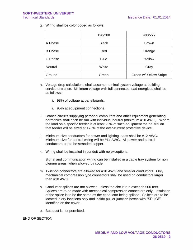
g. Wiring shall be color coded as follows:
120/208 480/277
A Phase Black Brown
B Phase Red Orange
C Phase Blue Yellow
Neutral White Gray
Ground Green Green w/ Yellow Stripe
h. Voltage drop calculations shall assume nominal system voltage at building service entrance. Minimum voltage with full connected load energized shall be as follows:
i. 98% of voltage at panelboards.
ii. 95% at equipment connections.
i. Branch circuits supplying personal computers and other equipment generating harmonics shall each be run with individual neutral (minimum #10 AWG). Where the load on a specific feeder is at least 25% of such equipment the neutral on that feeder will be sized at 173% of the over-current protective device.
j. Minimum size conductors for power and lighting loads shall be #12 AWG. Minimum size for control wiring will be #14 AWG. All power and control conductors are to be stranded copper.
k. Wiring shall be installed in conduit with no exceptions.
l. Signal and communication wiring can be installed in a cable tray system for non plenum areas, when allowed by code.
m. Twist-on connectors are allowed for #10 AWG and smaller conductors. Only mechanical compression type connectors shall be used on conductors larger than #10 AWG.
n. Conductor splices are not allowed unless the circuit run exceeds 500 feet. Splices are to be made with mechanical compression connectors only. Insulation of the splice is to be the same as the conductor being spliced. Splices are to be located in dry locations only and inside pull or junction boxes with “SPLICE” identified on the cover.
o. Bus duct is not permitted.
END OF SECTION
NORTHWESTERN UNIVERSITY Technical Standards Issuance Date: 01.01.2014
RACEWAYS AND BOXES 26 0533 - 1
DIVISION 26 – ELECTRICAL
SECTION 26 0533 – RACEWAYS AND BOXES
1. General: This section outlines the general requirements for raceways and boxes. Specific requirements are to be reviewed with the NU Project Manager during the design phases of the project
2. Design Considerations:
a. Provide dedicated raceway systems for the following:
i. Essential circuits.
ii. Stand-by feeders and circuits.
iii. Fire alarm systems.
iv. Security and Intrusion detection systems.
v. Access control systems.
vi. Telecommunication wiring.
vii. Public address system.
viii. Audio/visual systems.
ix. Environmental control systems.
x. Spare conduit in underground trenches. Spare shall be evaluated by Chief Electrician.
xi. Class I circuits; remote control and signaling circuits, less than 600V.
xii. Class II circuits; remote control and signaling circuits fed from a Class II limited power supply, 150V and less.
xiii. Where legally required.
b. Types of Conduit:
i. Electric metallic tubing “EMT” shall be utilized for concealed interior work, except as described herein.
ii. Intermediate grade conduit “IMC” shall be utilized for interior feeders in wet areas, damp areas, exterior, exposed in mechanical rooms and vertical drops to equipment. Review potential wet or damp areas with Chief Electrician.
NORTHWESTERN UNIVERSITY Technical Standards Issuance Date: 01.01.2014
RACEWAYS AND BOXES 26 0533 - 2
iii. Galvanized Rigid Steel Conduit “GRSC” shall be utilized in areas subject to physical damage in wet areas, exterior, within masonry walls, hollow tile walls, and all hazardous areas.
iv. PVC schedule 40 conduit shall be used in concrete slab and encased in 3" of concrete. In no case shall conduit be direct buried below slab. Provide PVC coated GRSC for all underground elbows. Use long sweep elbows for feeders above 600V.
1. 4 inch elbow: 36 inch minimum radius.
2. 5 inch elbow: 50 inch minimum radius.
3. 6 inch elbow: 61 inch minimum radius.
v. Flex conduit shall be used only for chasing existing walls, suspended lights in drop-in in suspended ceilings and connections to equipment subject to vibration, etc. Flexible conduit shall have green ground wire. Flexible conduit shall not exceed 6 feet in length.
c. Conduit Colors:
i. Yellow:
1. Feeders 600V – 12.4kV in vaults, gear rooms, electrical rooms, or electrical closets.
2. Gas monitoring outside vaults, gear rooms, electrical rooms, or electrical closets only. Conduit shall be tagged with a red strip at each connection point.
ii. Orange: Feeders 277V – 600V in vaults, gear rooms, electrical rooms, or electrical closets.
iii. White: Feeders 120V – 240V in vaults, gear rooms, electrical rooms, or electrical closets.
iv. Red: Fire alarm systems.
v. Blue: Building Automation System (BAS) and Security systems.
vi. Green: Dedicated ground and Hogan systems.
vii. Where conduit is exposed in public or finished areas, the conduits shall typically be painted to match the adjacent wall or ceiling color. The associated junction box covers shall be painted to match the Northwestern standard conduit color code above.
viii. Refer to Electrical Identification for labeling requirements.
NORTHWESTERN UNIVERSITY Technical Standards Issuance Date: 01.01.2014
RACEWAYS AND BOXES 26 0533 - 3
d. Conduit Size:
i. 3/8-inch flexible metallic conduit is allowed for final connection to lighting fixtures. Review specific requirements with NU Project Manager.
ii. 1/2-inch above grade allowed for controls, and some low voltage systems. Review specific requirements with NU Project Manager.
iii. 3/4-inch minimum for all line voltage above grade.
iv. 3/4-inch minimum for all security system conduits, including CCTV and access control systems.
v. 1-inch minimum below grade or in concrete for light loads.
vi. 4-inch minimum for main feeders, primary services and telecommunication lines.
e. Conduit Installation:
i. Raceways shall be installed with 30% or less conductor fill.
ii. Underground conduit and ducts shall be encased in a minimum 3" concrete envelope; trench and backfill will be done under this division of work; a tracer wire will be installed on the conduit and in the concrete encasement for future duct location requirements. Review specific requirements for tracer wire with NU Project Manager and Chief Electrician.
iii. Where conduits follow the same run, trapeze hangers (unistrut) may be utilized with provisions made for proper spacing and the use approved conduit straps. Suspending conduit from the bottom of a unistrut support is not permitted.
iv. Trapeze hangers shall utilize two 3/8” minimum threaded rods per cross member strut. Rod size is to be increased to match trapeze load with a 30% design safety factor.
v. Conduits are not to be embedded in the floor slab.
vi. PVC and PVC coated GRSC will be used in concrete. All PVC must have ground wire installed, minimum #12.
vii. Provide conduit sealing bushings for conduits 1-1/2 inches or greater and at all points where conduits enter the building from the outside or from below grade. Sealing fitting are to be used at all points where conduits enter air handlers and cold rooms.
1. All below grade conduit entries are to be specifically reviewed and approved with the NU Project Manager and NU Chief Electrician.
NORTHWESTERN UNIVERSITY Technical Standards Issuance Date: 01.01.2014
RACEWAYS AND BOXES 26 0533 - 4
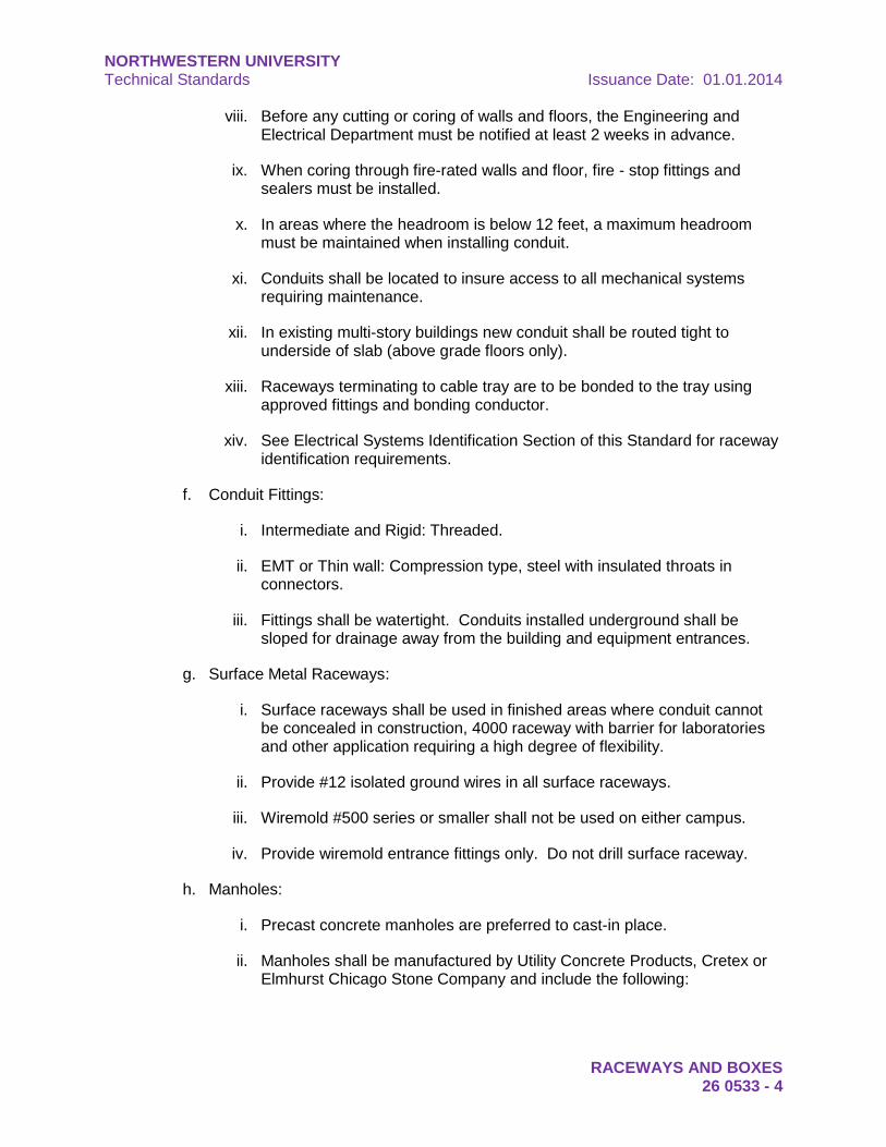
viii. Before any cutting or coring of walls and floors, the Engineering and Electrical Department must be notified at least 2 weeks in advance.
ix. When coring through fire-rated walls and floor, fire - stop fittings and sealers must be installed.
x. In areas where the headroom is below 12 feet, a maximum headroom must be maintained when installing conduit.
xi. Conduits shall be located to insure access to all mechanical systems requiring maintenance.
xii. In existing multi-story buildings new conduit shall be routed tight to underside of slab (above grade floors only).
xiii. Raceways terminating to cable tray are to be bonded to the tray using approved fittings and bonding conductor.
xiv. See Electrical Systems Identification Section of this Standard for raceway identification requirements.
f. Conduit Fittings:
i. Intermediate and Rigid: Threaded.
ii. EMT or Thin wall: Compression type, steel with insulated throats in connectors.
iii. Fittings shall be watertight. Conduits installed underground shall be sloped for drainage away from the building and equipment entrances.
g. Surface Metal Raceways:
i. Surface raceways shall be used in finished areas where conduit cannot be concealed in construction, 4000 raceway with barrier for laboratories and other application requiring a high degree of flexibility.
ii. Provide #12 isolated ground wires in all surface raceways.
iii. Wiremold #500 series or smaller shall not be used on either campus.
iv. Provide wiremold entrance fittings only. Do not drill surface raceway.
h. Manholes:
i. Precast concrete manholes are preferred to cast-in place.
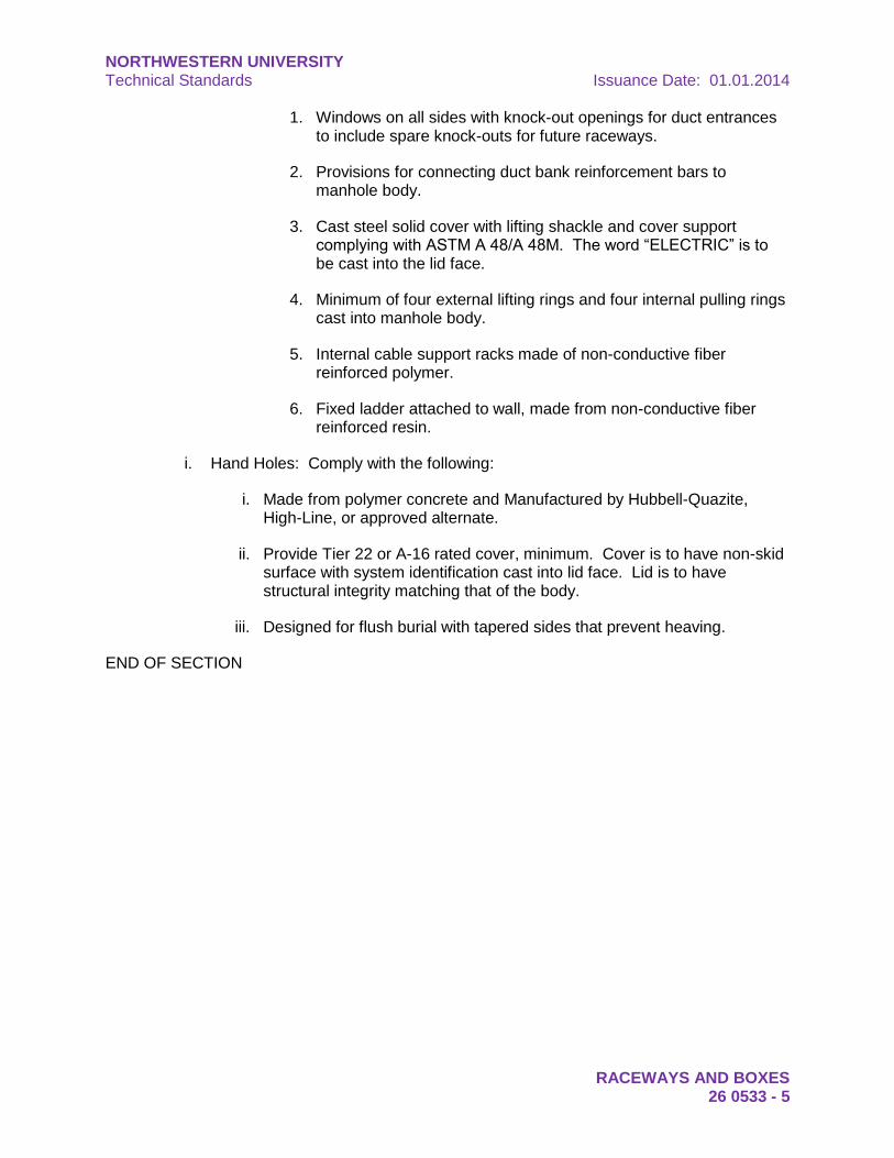
ii. Manholes shall be manufactured by Utility Concrete Products, Cretex or Elmhurst Chicago Stone Company and include the following:
NORTHWESTERN UNIVERSITY Technical Standards Issuance Date: 01.01.2014
RACEWAYS AND BOXES 26 0533 - 5
1. Windows on all sides with knock-out openings for duct entrances to include spare knock-outs for future raceways.
2. Provisions for connecting duct bank reinforcement bars to manhole body.
3. Cast steel solid cover with lifting shackle and cover support complying with ASTM A 48/A 48M. The word “ELECTRIC” is to be cast into the lid face.
4. Minimum of four external lifting rings and four internal pulling rings cast into manhole body.
5. Internal cable support racks made of non-conductive fiber reinforced polymer.
6. Fixed ladder attached to wall, made from non-conductive fiber reinforced resin.
i. Hand Holes: Comply with the following:
i. Made from polymer concrete and Manufactured by Hubbell-Quazite, High-Line, or approved alternate.
ii. Provide Tier 22 or A-16 rated cover, minimum. Cover is to have non-skid surface with system identification cast into lid face. Lid is to have structural integrity matching that of the body.
iii. Designed for flush burial with tapered sides that prevent heaving.
END OF SECTION
NORTHWESTERN UNIVERSITY Technical Standards Issuance Date: 01.01.2014
RACEWAYS AND BOXES 26 0533 - 6
This page intentionally left blank
NORTHWESTERN UNIVERSITY Technical Standards Issuance Date: 01.01.2014
IDENTIFICATION FOR ELECTRICAL SYSTEMS 26 0553 - 1
DIVISION 26 – ELECTRICAL
SECTION 26 0553 – IDENTIFICATION FOR ELECTRICAL SYSTEMS
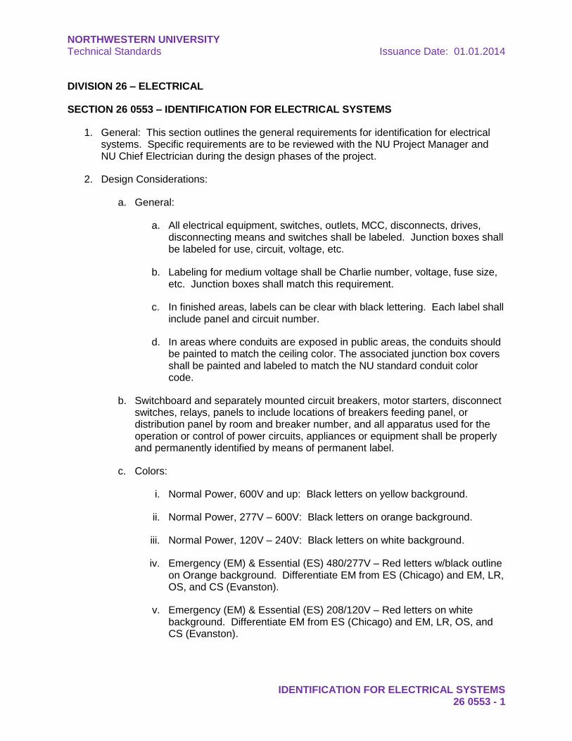
1. General: This section outlines the general requirements for identification for electrical systems. Specific requirements are to be reviewed with the NU Project Manager and NU Chief Electrician during the design phases of the project.
2. Design Considerations:
a. General:
a. All electrical equipment, switches, outlets, MCC, disconnects, drives, disconnecting means and switches shall be labeled. Junction boxes shall be labeled for use, circuit, voltage, etc.
b. Labeling for medium voltage shall be Charlie number, voltage, fuse size, etc. Junction boxes shall match this requirement.
c. In finished areas, labels can be clear with black lettering. Each label shall include panel and circuit number.
d. In areas where conduits are exposed in public areas, the conduits should be painted to match the ceiling color. The associated junction box covers shall be painted and labeled to match the NU standard conduit color code.
b. Switchboard and separately mounted circuit breakers, motor starters, disconnect switches, relays, panels to include locations of breakers feeding panel, or distribution panel by room and breaker number, and all apparatus used for the operation or control of power circuits, appliances or equipment shall be properly and permanently identified by means of permanent label.
c. Colors:
i. Normal Power, 600V and up: Black letters on yellow background.
ii. Normal Power, 277V – 600V: Black letters on orange background.
iii. Normal Power, 120V – 240V: Black letters on white background.
iv. Emergency (EM) & Essential (ES) 480/277V – Red letters w/black outline on Orange background. Differentiate EM from ES (Chicago) and EM, LR, OS, and CS (Evanston).
v. Emergency (EM) & Essential (ES) 208/120V – Red letters on white background. Differentiate EM from ES (Chicago) and EM, LR, OS, and CS (Evanston).
NORTHWESTERN UNIVERSITY Technical Standards Issuance Date: 01.01.2014
IDENTIFICATION FOR ELECTRICAL SYSTEMS 26 0553 - 2
d. Motors and other pieces of electrically operated apparatus shall be identified with suitable painted or stenciled lettering.
e. Panel directories shall be type written under a plastic or glass protective cover on panel door. Hand printed directory and stick on type labels are not acceptable. When panelboard directories are installed or updated, the date shall be identified on the directory. The name of the installing or updating contractor shall be indicated on the directory.
f. Three spare type panel directories will be provide along with As-Built drawing to the University. Provide one spare directory located at each panel.
g. Prior to typing directories, room numbers and area designation must be reviewed by the university architect and university supervising electrician in case of conflict with construction drawing designations.
h. Laboratory raceway receptacles shall display source panel and circuit numbers.
i. Raceways in electrical rooms and vaults are to be identified every 10 feet to indicate voltage, amperage, source switch number, and destination.
j. Junction box covers are to be marked with the source panel and circuit numbers for conductors found within the junction box. Use the same color coding as with raceway identification.
k. Receptacles, switches and disconnects are to be labeled with the voltage, phase and amperage in addition to the source panel and circuit number/s.
END OF SECTION
NORTHWESTERN UNIVERSITY Technical Standards Issuance Date: 01.01.2014
LOW VOLTAGE TRANSFORMERS 26 2200 - 1
DIVISION 26 – ELECTRICAL
SECTION 26 2200 – LOW VOLTAGE TRANSFORMERS
1. General: This section outlines the general requirements for low voltage transformers. Specific requirements are to be reviewed with the NU Project Manager and NU Chief Electrician during the design phases of the project.
2. Design Considerations:
a. Transformers are to have the following maximum rated rise temperatures over a 40°C ambient:
i. 150kVA and above; 80°C.
ii. 45kVA – 112.5kVA; 115°C.
iii. 30kVA and below; 150°C.
b. Appropriate K factor transformers shall be installed in laboratories and area of multiple computer use to offset effects of harmonics.
c. Transformers are to have 220°C class insulation.
d. Transformers are to have copper windings.
e. Transformers are to be rated NEMA TP-1 efficiency or higher.
f. Transformers are to be mounted on vibration isolation pads.
g. Transformers are limited to the following maximum sound levels:
i. 25kVA and below; 45dB.
ii. 30kVA – 150kVA; 50dB.
iii. 225kVA – 300kVA; 55dB.
iv. Above 300kVA; 60dB.
END OF SECTION
NORTHWESTERN UNIVERSITY Technical Standards Issuance Date: 01.01.2014
LOW VOLTAGE TRANSFORMERS 26 2200 - 2
This page intentionally left blank
NORTHWESTERN UNIVERSITY Technical Standards Issuance Date: 01.01.2014
LOW VOLTAGE SWITCHGEAR 26 2300 - 1
DIVISION 26 – ELECTRICAL
SECTION 26 2300 – LOW VOLTAGE SWITCHGEAR
1. General: This section outlines the general requirements for low voltage switchgear. Specific requirements are to be reviewed with the NU Project Manager and NU Chief Electrician during the design phases of the project.
2. Design Considerations:
a. Locations:
i. Main switchgear is not to be located in areas of elevated temperatures or high humidity.
ii. A separate switchgear room in close proximity to the transformer vault is recommended.
iii. Mechanical ducts, water pipes, drain pipes, etc. will not be permitted in electrical switchgear room.
iv. Switchgear is to be self-supporting and placed on a housekeeping pad.
b. Bussing of the switchgear should be of sufficient capacity to accommodate the next size larger transformer bank. Main breaker should be similarly sized. Buss bracing shall be for the expected fault current for the next size transformer, a minimum of 65,000 amperes for 30 cycles on any switchgear. Overcurrent devices are to have an interrupt rating the same as the switchgear fault current rating. Prepared spaces shall be provided and shall not be less than 25% of the switchgear spaces in each frame size at completion of the project.
c. Main switchgear is to be UL1558 listed and to comply with ANSI C37.20.1.
d. Switchgear bus is to be insulated, silver plated copper, 98% conductivity, size based on 1000 amperes per square inch current density. An interior ground bus and terminals are to be provided along with a jumper to the system neutral where required for service entrance. Switchgear bus is to have bolted connections. Provide 100% neutral where indicated.
e. Vertical bus compartment is to be separated from the horizontal bus with an insulated metal barrier.
f. All switchgear compartments are to be segregated into cubicles with a divider between the device cubicle and the bus. Each breaker cubicle is to have shutters that allow draw-out circuit breakers to be installed with its finger contacts passing through the shutters to make contact with the vertical bus. The shutter is to spring shut when the breaker contacts have been pulled free from the bus.
NORTHWESTERN UNIVERSITY Technical Standards Issuance Date: 01.01.2014
LOW VOLTAGE SWITCHGEAR 26 2300 - 2
g. Rear cable compartments are to be separated vertically with glass polyester dividers. Cable compartments are to be separated from vertical and horizontal buses with an insulted metal barrier.
h. Feeder to switchgear may be wire in conduit or feeder bus. Wire in conduit where multiple conductors per phase are required must be precut such that all conductors per phase are the same identical length after connection. Current capacity of “bus ways” and size of conduit for conductors shall be sized to accommodate the next size transformer bank for future expansion.
i. Each switchgear vertical section is to be labeled with the vertical bus voltage, amperage, phase, and fault current bracing rating. Each switchgear circuit breaker is to be labeled with the load identification, breaker amperage, voltage and phase.
j. Provide provisions and housekeeping pad for an additional vertical section to be added to switchgear line-up. Double-ended switchgear is to have provisions and housekeeping pad for two additional vertical sections. Room layout is to accommodate code required clearances for both current and future sections.
k. All switchgear circuit breakers are to be power style UL1066 listed, ANSI C37.13 air frame or insulated-case type with electronic trip in draw-out cubicles, 800A frame size minimum. Electronic trip modules are to have adjustments for long time pickup and delay, short time pickup and delay, instantaneous pickup and delay. All circuit breakers are to be 100% rated. Main circuit breakers are to have an arc flash maintenance switch that minimizes the instantaneous delay to allow for lower required PPE level during maintenance.
l. Where ground fault protection is required by code or for coordination, ground fault modules are to have adjustable pickup current and delay with I2T “in” and “out” functions. Ground fault trip modules are to indicate ground current and have programmable alarm contacts to indicate an elevated ground current condition.
m. If ground fault protection is required on the main circuit breaker/s, two levels of ground fault protection is required to allow coordination of ground fault devices and avoid complete system outages due to ground faults.
n. Switchgear with zone protective interlocking is allowed as an alternate to having circuit breakers with individual trip settings. Zone protective interlocking switchgear will utilize a centralized CPU to monitor all circuit breaker trip functions for each feeder. The CPU will open selected breakers upon detection of a condition that is out of range for the setting of that breaker.
o. Install 200kA surge protection devices on all service entrance switchgear.
p. Surge protection devices are to be mounted externally to switchgear with no more than 36” conductor length.
q. Customer metering is to be provided in addition to utility metering. Provide pulse meter with ComEd meters required, tied to NUELEC SCADA equipment.
NORTHWESTERN UNIVERSITY Technical Standards Issuance Date: 01.01.2014
LOW VOLTAGE SWITCHGEAR 26 2300 - 3
r. Rear covers shall be hinged door with Corbin #4T3142 key lock. Lock type shall be same for both campuses.
s. Front covers shall be formed and mounted with thumb screws. All front covers over draw out devices or with meters mounted on them shall be hung with loose pin hinges.
t. An overhead breaker trolley with hoist is to be provided for each switchgear line-up. Trolley rails are to be installed to allow pull boxes to be installed above switchgear without interfering with the trolley.
u. Switchgear is to be divided into shipping splits sized to allow delivery and installation into existing facilities. Electrical contractor is responsible for reassembly and testing of installed switchgear to factory tolerances.
v. A mimic bus made from laminated plastic is to be attached to the front of the switchgear with screws. The mimic bus is to indicate the bus pattern as it passes through the switchgear. The mimic bus is to show both the horizontal and vertical buses and all overcurrent devices.
w. Arc-flash labels are to be applied to all switchgear compartments.
x. Switchgear in new facilities shall be manufactured by Cutler Hammer, G.E., Gus Berthold. Switchgear in existing facilities shall match the manufacturer of equipment already being used.
END OF SECTION
NORTHWESTERN UNIVERSITY Technical Standards Issuance Date: 01.01.2014
LOW VOLTAGE SWITCHGEAR 26 2300 - 4
This page intentionally left blank
NORTHWESTERN UNIVERSITY Technical Standards Issuance Date: 01.01.2014
SWITCHBOARDS 26 2413 - 1
DIVISION 26 – ELECTRICAL
SECTION 26 2413 – SWITCHBOARDS
1. General: This section outlines the general requirements for switchboards. Specific requirements are to be reviewed with the NU Project Manager and NU Chief Electrician during the design phases of the project.
2. Design Considerations:
a. Location:
i. Main switchboards are not to be located in areas of elevated temperatures or high humidity.
ii. Provide a separate switchboard room in close proximity to the transformer vault.
iii. Mechanical ducts, water pipes, drain pipes, etc. will not be permitted in electrical switchboard room.
b. Bussing of the switchboard should be of sufficient capacity to accommodate the next size larger transformer bank. Main breaker should be similarly sized. Buss bracing shall be for the expected fault current of the next size transformer, a minimum of 65,000 amperes on any switchboard. Overcurrent devices are to have an interrupt rating the same as the switchboard fault current rating. Blank spaces shall be provided and shall not be less than 25% of the switchboard spaces in each frame size.
c. All bus joints shall be bolted and be visible with switchboard energized for inspection and readily accessible with the board de-energized for maintenance. Windows shall be provided for infrared capability at joint locations.
d. Main switchboards are to be UL listed dead front (UL891) with silver plated copper bus, size based on 1000 amperes per square inch current density. An interior ground bus and terminals are to be provided along with a jumper to the system neutral. All ground terminations must be cadwelded.
e. Feeder to switchboard may be wire in conduit. Wire in conduit where multiple conductors per phase are required must be precut such that all conductors per phase are the same identical length after connection. Current capacity of “bus ways” and size of conduit for conductors shall be sized to accommodate the next size transformer bank for future expansion.
f. Circuit breakers are to be used for protective devices including main disconnect. Fuses are to be avoided. Where fault currents warrant, current limiting devices are to be specified. All breakers are to be identified and a complete index provided. All circuit breakers to have threaded bolts on bus connections. Circuit breakers employing plug-in, finger type bus connections are not acceptable.
NORTHWESTERN UNIVERSITY Technical Standards Issuance Date: 01.01.2014
SWITCHBOARDS 26 2413 - 2
Blank spaces shall be provided and shall not be less than 25% of the switchboard spaces in each frame size.
g. Each switchboard vertical section is to be labeled with the vertical bus voltage, amperage, phase, and fault current bracing rating. Each switchboard circuit breaker is to be labeled with the load identification, breaker amperage, voltage and phase.
h. Main and Tie Breakers are to be insulated-case type with electronic trip in draw-out cubicles. Branch breakers 600A trip and above are to be individually mounted insulated-case type with electronic trip. 800A frame size minimum. Electronic trip modules are to have adjustments for long time pickup and delay, short time pickup and delay, instantaneous pickup and delay. All insulated-case breakers are 100% rated. Other options: Arc flash maintenance switch, arch flash detection and control relay.
i. Where ground fault protection is required by code or for coordination, ground fault modules are to have adjustable pickup current and delay with I2T “in” and “out” functions.
j. If ground fault protection is required on the main breaker, ground fault is to be provided on branch breakers where ground faults commonly occur (feeds to lighting panels, motor control equipment, etc.) to allow coordination of ground fault devices.
k. Branch breakers rated below 600 amps to 400 amps are to be molded-case, current-limiting type with electronic trip including adjustable trip settings. No circuit breakers with trip ratings below 400 amps are to be installed in service entrance switchboards except to feed surge protection devices.
l. Install 200kA surge protection devices on all service entrance switchboards.
m. Surge protection devices are to be mounted externally to switchboard with no more than 36” conductor length.
n. Customer metering is to be provided in addition to utility metering. Metering should be added by distribution, such as Mechanical meter, Kitchen Meter, RP/LP metering etc. Metering shall be fused and have CT shorting blocks. (Provide Diagram)
o. Rear covers shall be hinged door with Corbin #4T3142 key lock. Lock type shall be same for both campuses.
p. Front cover shall be formed and mounted with thumb screws. All front covers over draw out devices or with meters mounted on them shall be hung with loose pin switchboard type hinges.
q. Arc-flash labels are to be applied to switchboard compartments. Labels shall say all class information and proper PPE.
NORTHWESTERN UNIVERSITY Technical Standards Issuance Date: 01.01.2014
SWITCHBOARDS 26 2413 - 3
r. Switchboards in new facilities shall be manufactured by Cutler Hammer, Gus Berthold, or Siemens. Switchboards in existing facilities shall match the manufacturer of equipment already being used.
s. Switchboard bays shall be individual, free standing units with steel angles and fully welded construction.
i. Front covers shall be 12 gauge formed 1” deep hinged covers to be hung with switchboards type loose pin type and held closed with knurled thumb screws.
ii. Interiors brackets and supports to be #10 gauge steel arc welded frame. Brackets by means of bolting will not be accepted.
iii. Top and sides plates shall be 12 gauge or better steel, buss bar shall be copper, 98% conductivity, size based on 1000A per sq inch current density.
iv. All bus joints to be silver plated all bolts shall be grade 5 bolts. All equipment shall bear the UL INC dead front switchboard label.
END OF SECTION
NORTHWESTERN UNIVERSITY Technical Standards Issuance Date: 01.01.2014
SWITCHBOARDS 26 2413 - 4
This page intentionally left blank
NORTHWESTERN UNIVERSITY Technical Standards Issuance Date: 01.01.2014
PANELBOARDS 26 2416 - 1
DIVISION 26 – ELECTRICAL
SECTION 26 2416 – PANELBOARDS
1. General: This section outlines the general requirements for panelboards. Specific requirements are to be reviewed with the NU Project Manager and NU Chief Electrician during the design phases of the project.
2. Design Considerations:
a. Panelboards shall be surface mounted in electric closets. Panel mounting method for different bus ratings as follows:
i. 225A and below;
ii. 400A – 600A;
iii. 800A – 1200A;
iv. Above 1200A; Floor mounted.
b. Panelboards recessed in walls shall have a minimum of four 3/4-inch spare conduits stubbed into ceiling space for future load requirements.
c. Nameplate ampacity of panel shall be 200% of connected load.
d. Neutral bus ampacity shall be rated 200% for panels feeding harmonic type loads.
e. 100 ampere panelboards shall contain space for a maximum of 30 circuits, 125 ampere panelboards shall contain space for a maximum of 36 circuits; 225 ampere panelboards shall contain space for a maximum of 42 circuits.
f. Include in each panel one spare 20 ampere, 1 pole circuit breaker a minimum of 25% of the total number of circuit breakers in panel.
g. Use combination AFCI breakers in living areas.
h. Arc-flash labels are to be applied to all panelboards.
i. Panelboard assembly will adhere to the following:
i. Busses shall be copper and must be located in the rear of the panelboard cabinet.
ii. Minimum AIC ratings:
1. 35kA for 480/277V.
2. 10kA for 208/120V.
NORTHWESTERN UNIVERSITY Technical Standards Issuance Date: 01.01.2014
PANELBOARDS 26 2416 - 2
iii. Circuit breakers will be mounted on suitable supporting members at the front of the cabinet and connected via suitable straps of lugs to the bussing at the rear of the cabinet. All circuit breakers to have threaded bolts on bus connections. Circuit breakers employing plug-in, finger type connections are not acceptable.
iv. Breakers shall be bolt-on type and shall be removable without disturbing the bussing and/or other branch protective devices. No plug-in breakers allowed.
v. Panelboards shall be keyed alike with Corbin #4T3142 key lock in each building and attention must be given additions and revisions to existing buildings; all keying must be cleared with university lock shop.
vi. Panelboard covers to be hinged with piano style hinges with door-in-door construction.
vii. Panelboard tubs are to have fully welded construction and not to have concentric knock-outs.
viii. Exterior panelboards shall have heaters.
ix. Panelboards shall be dead front, totally enclosed, convertible type.
x. For the Chicago Campus, all fluorescent lighting circuits are to be on a 15 ampere breaker with #12 wire and comply with Article 14-24-250 (87-410.26).
xi. There are numerous Northwestern buildings with electrical feeders and risers exceeding 80% capacity. Existing loads must be confirmed prior to adding any additional load. New lighting or power panels installed on existing risers must be approved by Northwestern Supervising Electrician.
j. Panelboards in new facilities shall be manufactured by Gus Berthold. Panelboards in existing facilities shall match the manufacturer of equipment already being used. Other manufacturers are to be approved by the Supervising Electrician.
END OF SECTION
NORTHWESTERN UNIVERSITY Technical Standards Issuance Date: 01.01.2014
MOTOR CONTROL CENTERS 26 2419 - 1
DIVISION 26 – ELECTRICAL
SECTION 26 2419 – MOTOR CONTROL CENTERS
1. General: This section outlines the general requirements for motor control centers. Specific requirements are to be reviewed with the NU Project Manager and NU Chief Electrician during the design phases of the project.
2. Design Considerations:
a. Motor starters and overload protective devices shall be provided for all motors ½ HP or larger. Receptacles may be used for disconnects only on motors less than 1/2 HP and only as allowed by the Chicago Electrical Code and the N.E.C. and is recommended for all hot water circulating pumps.
b. Motors shall be 480V, 3 phase except for motors less than 1/2 HP.
c. Starters shall be grouped into motor control centers. Individual starters except in isolated cases are to be avoided. Each starter shall have a hand/off/automatic selector switch pilot light (run), two normally open and two normally closed auxiliary contacts.
d. Control power for starter must originate from MCC cubicle to maintain voltage continuity with disconnection of power to starter or MCC.
e. Heater overloads will be sized at no more than 130% of running load of motor.
f. Lockable, heavy duty safety non-fused disconnect switches are to be located near motor which are not within sight of MCC.
g. Pushbuttons for starters will have positive lockout on “OFF” position.
h. Motors over 30 HP shall have reduced voltage or solid-state starting and power factor correction.
i. Minimum NEMA size for starters shall be number 1.
j. Motor control centers shall have copper bussing.
k. Motor starters are to use fuses for overcurrent protection.
l. Provide minimum 500va control power transformer in each starter cubicle. Size larger transformers as needed with 100% spare capacity.
m. Motor starters are to have phase loss/under voltage detection relays and shall open contactor upon a loss of any one or two phases or voltage that is 30% below rated system voltage with a 5 second adjustable delay.
n. Arc-flash labels are to be applied to all motor control devices including VFDs.
NORTHWESTERN UNIVERSITY Technical Standards Issuance Date: 01.01.2014
MOTOR CONTROL CENTERS 26 2419 - 2
o. Provide “Open / Close” and “Run / Stop” light in MCC
p. Motor control centers shall have fully welded construction, welded frames, and infrared windows.
q. Motor control centers shall be Allen Bradley, Cutler-Hammer, Gus Berthold, or Siemens.
END OF SECTION
NORTHWESTERN UNIVERSITY Technical Standards Issuance Date: 01.01.2014
ELECTRICITY METERING 26 2713 - 1
DIVISION 26 – ELECTRICAL
SECTION 26 2713 – ELECTRICITY METERING
1. General: This section outlines the general requirements for metering of electrical systems. Specific requirements are to be reviewed with the NU Project Manager and NU Chief Electrician during the design phases of the project.
2. Power Meters:
a. The meter shall be UL listed and CE marked.
b. Power meter shall be designed for Multifunction Electrical Measurement on 3 phase power systems.
i. Meter shall support 3- Element Wye, 2.5 Element Wye, 2 Element delta, 4 wire Delta systems.
ii. Surge shall conform to IEEE C37.90.1 and ANSI C62.41 (6 kV)
iii. The meter shall be user programmable for voltage range to any CT or PT ratio.
iv. Meter shall have a burden of not more than 0.36VA per phase, Max at 660V, 0.01VA and 120 Volts.
v. Meter shall have a burden of not more than 0.005VA per phase, Max at 11 Amps.
vi. The meter shall accept a voltage input range from 20 up to 576 Volts Line to Neural, and a range from 0 up to 721 Volts from Line to Line.
vii. Meter shall accept a current reading of up to 10 Amps continuous. Start up current for a 5 Amp input shall be no greater than 0.005 Amps.
c. Power meter shall use a dual input method for current inputs. Method one shall allow the CT to pass directly through the meter without any physical termination on the meter, ensuring the meter cannot be a point of failure on the CT circuit. The second method shall provide additional termination pass-through bars, allowing the CT leads to be terminated on the meter. The meter must support both termination methods.
i. Fault Current Withstand shall be 100 Amps for 10 seconds, 300 Amps for 3 seconds and 500 Amps for 1 second.
ii. Pass through wire gauge dimension of 0.177"/4.5 mm shall be available.
iii. All inputs and outputs shall be galvanically isolated to 2500 Volts AC.
NORTHWESTERN UNIVERSITY Technical Standards Issuance Date: 01.01.2014
ELECTRICITY METERING 26 2713 - 2
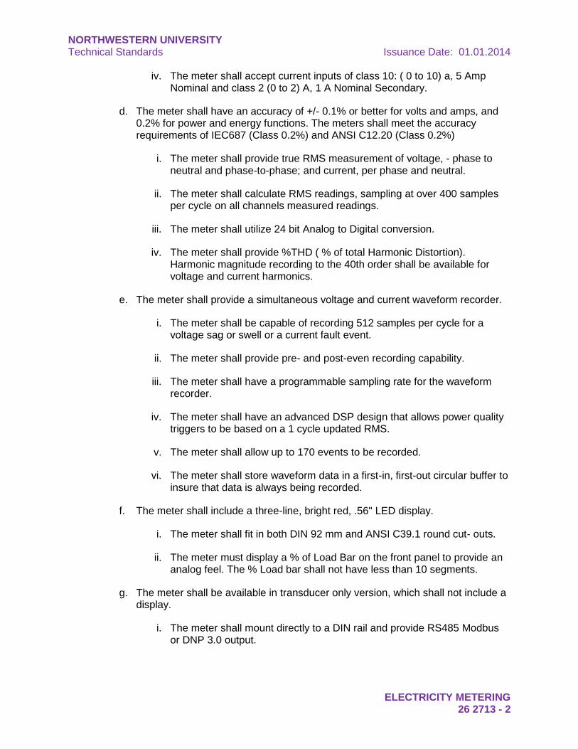
iv. The meter shall accept current inputs of class 10: ( 0 to 10) a, 5 Amp Nominal and class 2 (0 to 2) A, 1 A Nominal Secondary.
d. The meter shall have an accuracy of +/- 0.1% or better for volts and amps, and 0.2% for power and energy functions. The meters shall meet the accuracy requirements of IEC687 (Class 0.2%) and ANSI C12.20 (Class 0.2%)
i. The meter shall provide true RMS measurement of voltage, - phase to neutral and phase-to-phase; and current, per phase and neutral.
ii. The meter shall calculate RMS readings, sampling at over 400 samples per cycle on all channels measured readings.
iii. The meter shall utilize 24 bit Analog to Digital conversion.
iv. The meter shall provide %THD ( % of total Harmonic Distortion). Harmonic magnitude recording to the 40th order shall be available for voltage and current harmonics.
e. The meter shall provide a simultaneous voltage and current waveform recorder.
i. The meter shall be capable of recording 512 samples per cycle for a voltage sag or swell or a current fault event.
ii. The meter shall provide pre- and post-even recording capability.
iii. The meter shall have a programmable sampling rate for the waveform recorder.
iv. The meter shall have an advanced DSP design that allows power quality triggers to be based on a 1 cycle updated RMS.
v. The meter shall allow up to 170 events to be recorded.
vi. The meter shall store waveform data in a first-in, first-out circular buffer to insure that data is always being recorded.
f. The meter shall include a three-line, bright red, .56" LED display.
i. The meter shall fit in both DIN 92 mm and ANSI C39.1 round cut- outs.
ii. The meter must display a % of Load Bar on the front panel to provide an analog feel. The % Load bar shall not have less than 10 segments.
g. The meter shall be available in transducer only version, which shall not include a display.
i. The meter shall mount directly to a DIN rail and provide RS485 Modbus or DNP 3.0 output.
NORTHWESTERN UNIVERSITY Technical Standards Issuance Date: 01.01.2014
ELECTRICITY METERING 26 2713 - 3
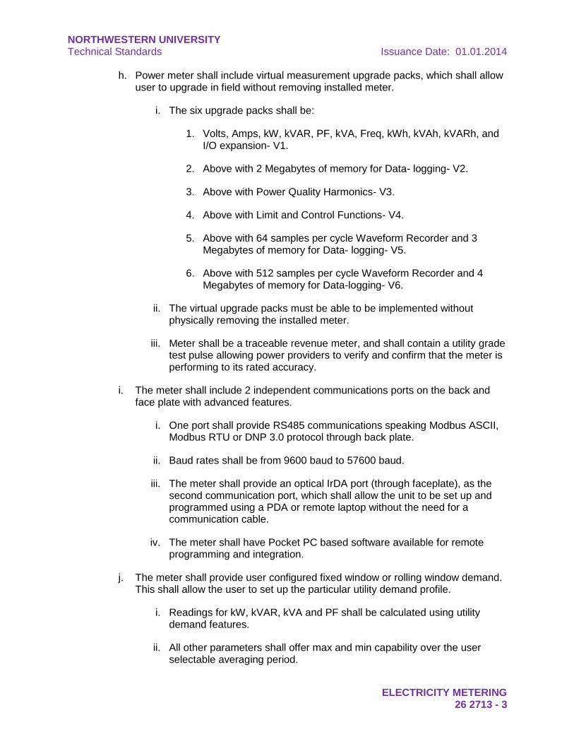
h. Power meter shall include virtual measurement upgrade packs, which shall allow user to upgrade in field without removing installed meter.
i. The six upgrade packs shall be:
1. Volts, Amps, kW, kVAR, PF, kVA, Freq, kWh, kVAh, kVARh, and I/O expansion- V1.
2. Above with 2 Megabytes of memory for Data- logging- V2.
3. Above with Power Quality Harmonics- V3.
4. Above with Limit and Control Functions- V4.
5. Above with 64 samples per cycle Waveform Recorder and 3 Megabytes of memory for Data- logging- V5.
6. Above with 512 samples per cycle Waveform Recorder and 4 Megabytes of memory for Data-logging- V6.
ii. The virtual upgrade packs must be able to be implemented without physically removing the installed meter.
iii. Meter shall be a traceable revenue meter, and shall contain a utility grade test pulse allowing power providers to verify and confirm that the meter is performing to its rated accuracy.
i. The meter shall include 2 independent communications ports on the back and face plate with advanced features.
i. One port shall provide RS485 communications speaking Modbus ASCII, Modbus RTU or DNP 3.0 protocol through back plate.
ii. Baud rates shall be from 9600 baud to 57600 baud.
iii. The meter shall provide an optical IrDA port (through faceplate), as the second communication port, which shall allow the unit to be set up and programmed using a PDA or remote laptop without the need for a communication cable.
iv. The meter shall have Pocket PC based software available for remote programming and integration.
j. The meter shall provide user configured fixed window or rolling window demand. This shall allow the user to set up the particular utility demand profile.
i. Readings for kW, kVAR, kVA and PF shall be calculated using utility demand features.
ii. All other parameters shall offer max and min capability over the user selectable averaging period.
NORTHWESTERN UNIVERSITY Technical Standards Issuance Date: 01.01.2014
ELECTRICITY METERING 26 2713 - 4
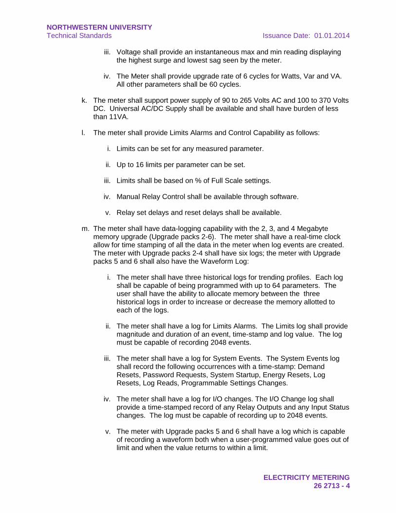
iii. Voltage shall provide an instantaneous max and min reading displaying the highest surge and lowest sag seen by the meter.
iv. The Meter shall provide upgrade rate of 6 cycles for Watts, Var and VA. All other parameters shall be 60 cycles.
k. The meter shall support power supply of 90 to 265 Volts AC and 100 to 370 Volts DC. Universal AC/DC Supply shall be available and shall have burden of less than 11VA.
l. The meter shall provide Limits Alarms and Control Capability as follows:
i. Limits can be set for any measured parameter.
ii. Up to 16 limits per parameter can be set.
iii. Limits shall be based on % of Full Scale settings.
iv. Manual Relay Control shall be available through software.
v. Relay set delays and reset delays shall be available.
m. The meter shall have data-logging capability with the 2, 3, and 4 Megabyte memory upgrade (Upgrade packs 2-6). The meter shall have a real-time clock allow for time stamping of all the data in the meter when log events are created. The meter with Upgrade packs 2-4 shall have six logs; the meter with Upgrade packs 5 and 6 shall also have the Waveform Log:
i. The meter shall have three historical logs for trending profiles. Each log shall be capable of being programmed with up to 64 parameters. The user shall have the ability to allocate memory between the three historical logs in order to increase or decrease the memory allotted to each of the logs.
ii. The meter shall have a log for Limits Alarms. The Limits log shall provide magnitude and duration of an event, time-stamp and log value. The log must be capable of recording 2048 events.
iii. The meter shall have a log for System Events. The System Events log shall record the following occurrences with a time-stamp: Demand Resets, Password Requests, System Startup, Energy Resets, Log Resets, Log Reads, Programmable Settings Changes.
iv. The meter shall have a log for I/O changes. The I/O Change log shall provide a time-stamped record of any Relay Outputs and any Input Status changes. The log must be capable of recording up to 2048 events.
v. The meter with Upgrade packs 5 and 6 shall have a log which is capable of recording a waveform both when a user-programmed value goes out of limit and when the value returns to within a limit.
NORTHWESTERN UNIVERSITY Technical Standards Issuance Date: 01.01.2014
ELECTRICITY METERING 26 2713 - 5
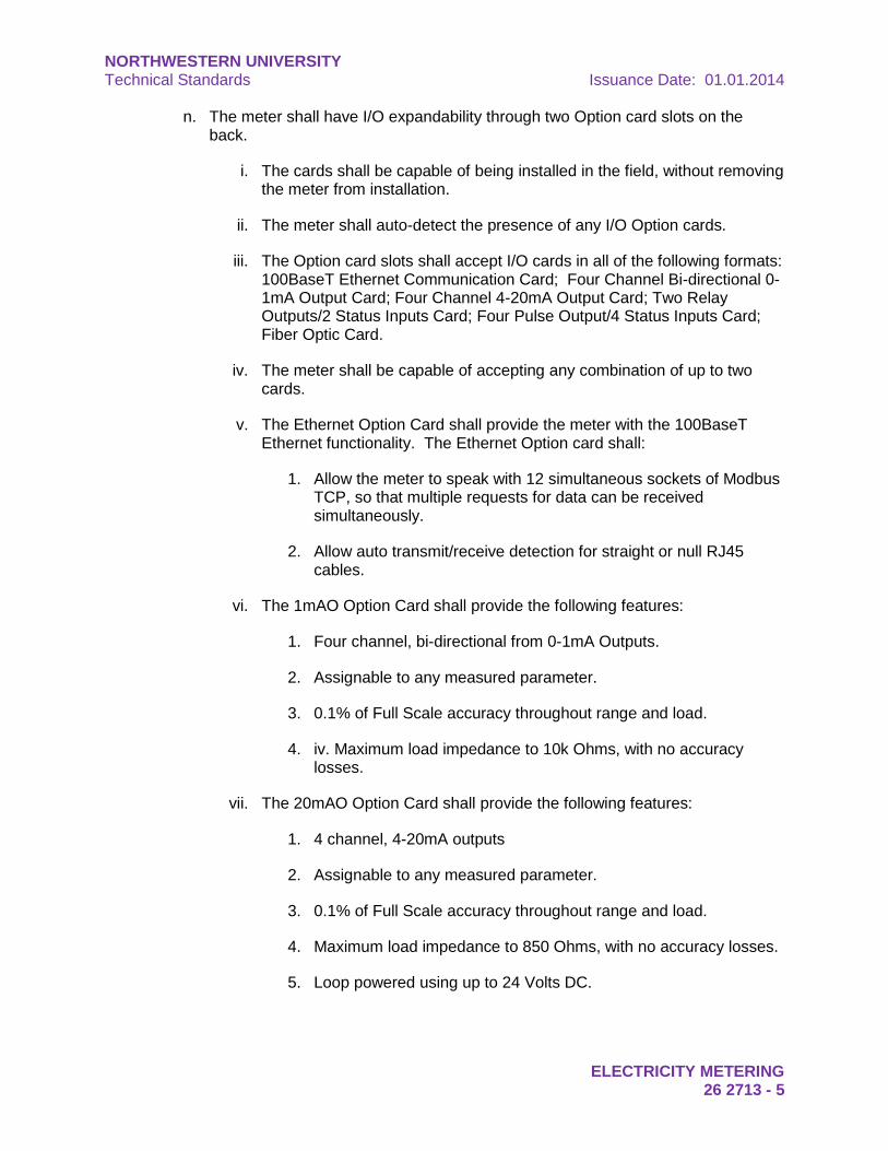
n. The meter shall have I/O expandability through two Option card slots on the back.
i. The cards shall be capable of being installed in the field, without removing the meter from installation.
ii. The meter shall auto-detect the presence of any I/O Option cards.
iii. The Option card slots shall accept I/O cards in all of the following formats: 100BaseT Ethernet Communication Card; Four Channel Bi-directional 0-1mA Output Card; Four Channel 4-20mA Output Card; Two Relay Outputs/2 Status Inputs Card; Four Pulse Output/4 Status Inputs Card; Fiber Optic Card.
iv. The meter shall be capable of accepting any combination of up to two cards.
v. The Ethernet Option Card shall provide the meter with the 100BaseT Ethernet functionality. The Ethernet Option card shall:
1. Allow the meter to speak with 12 simultaneous sockets of Modbus TCP, so that multiple requests for data can be received simultaneously.
2. Allow auto transmit/receive detection for straight or null RJ45 cables.
vi. The 1mAO Option Card shall provide the following features:
1. Four channel, bi-directional from 0-1mA Outputs.
2. Assignable to any measured parameter.
3. 0.1% of Full Scale accuracy throughout range and load.
4. iv. Maximum load impedance to 10k Ohms, with no accuracy losses.
vii. The 20mAO Option Card shall provide the following features:
1. 4 channel, 4-20mA outputs
2. Assignable to any measured parameter.
3. 0.1% of Full Scale accuracy throughout range and load.
4. Maximum load impedance to 850 Ohms, with no accuracy losses.
5. Loop powered using up to 24 Volts DC.
NORTHWESTERN UNIVERSITY Technical Standards Issuance Date: 01.01.2014
ELECTRICITY METERING 26 2713 - 6
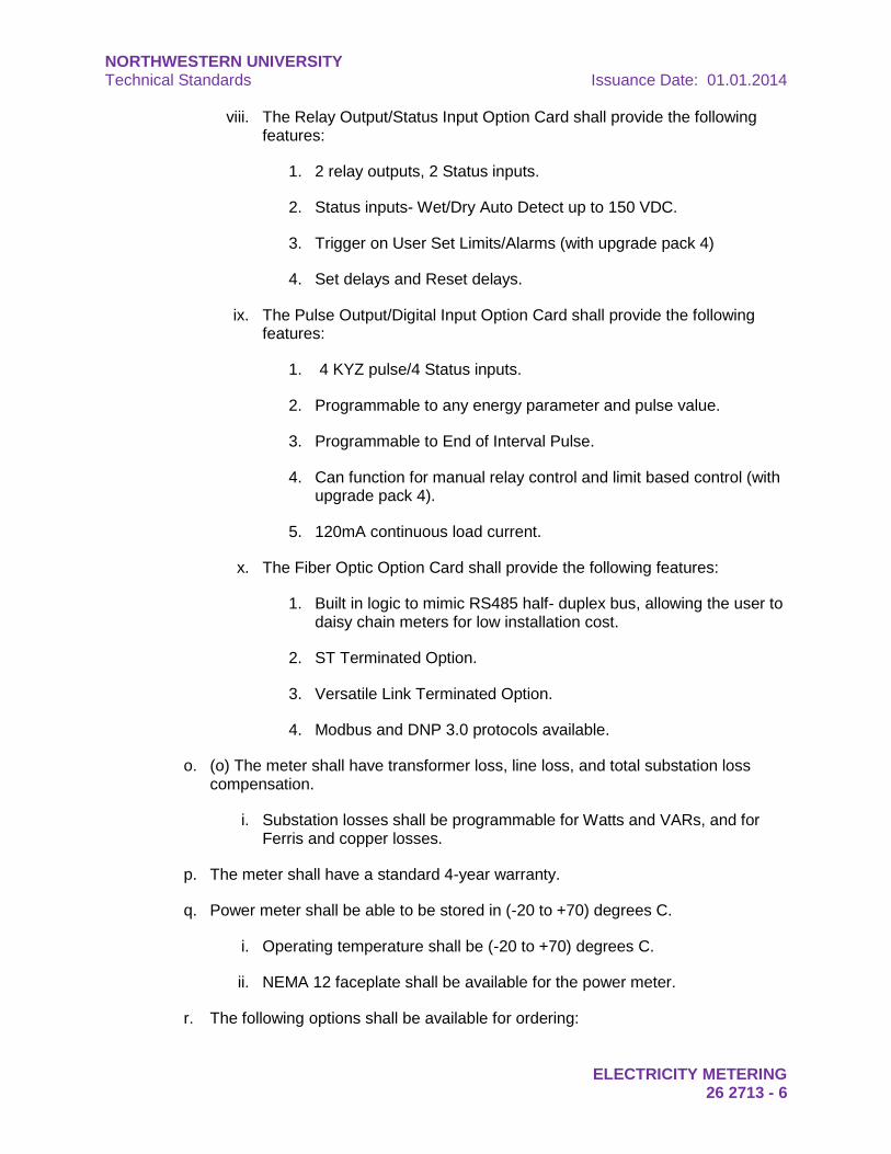
viii. The Relay Output/Status Input Option Card shall provide the following features:
1. 2 relay outputs, 2 Status inputs.
2. Status inputs- Wet/Dry Auto Detect up to 150 VDC.
3. Trigger on User Set Limits/Alarms (with upgrade pack 4)
4. Set delays and Reset delays.
ix. The Pulse Output/Digital Input Option Card shall provide the following features:
1. 4 KYZ pulse/4 Status inputs.
2. Programmable to any energy parameter and pulse value.
3. Programmable to End of Interval Pulse.
4. Can function for manual relay control and limit based control (with upgrade pack 4).
5. 120mA continuous load current.
x. The Fiber Optic Option Card shall provide the following features:
1. Built in logic to mimic RS485 half- duplex bus, allowing the user to daisy chain meters for low installation cost.
2. ST Terminated Option.
3. Versatile Link Terminated Option.
4. Modbus and DNP 3.0 protocols available.
o. (o) The meter shall have transformer loss, line loss, and total substation loss compensation.
i. Substation losses shall be programmable for Watts and VARs, and for Ferris and copper losses.
p. The meter shall have a standard 4-year warranty.
q. Power meter shall be able to be stored in (-20 to +70) degrees C.
i. Operating temperature shall be (-20 to +70) degrees C.
ii. NEMA 12 faceplate shall be available for the power meter.
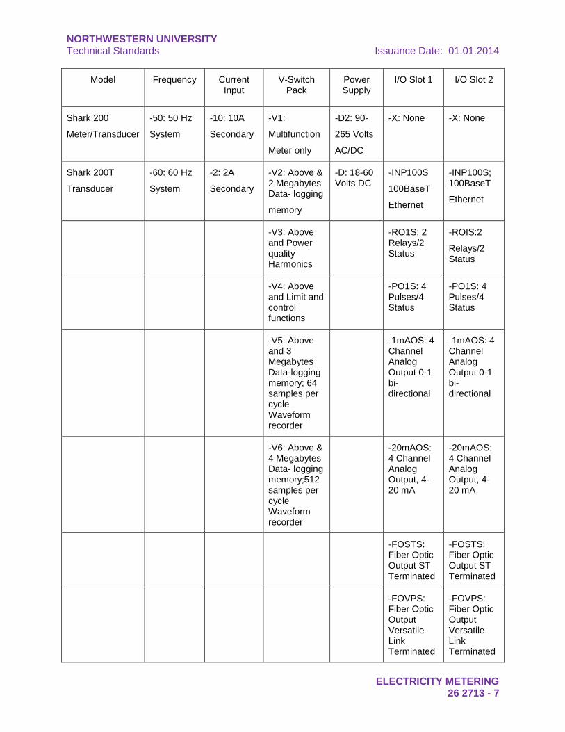
r. The following options shall be available for ordering:
NORTHWESTERN UNIVERSITY Technical Standards Issuance Date: 01.01.2014
ELECTRICITY METERING 26 2713 - 7
Model Frequency Current Input
V-Switch Pack
Power Supply
I/O Slot 1 I/O Slot 2
Shark 200
Meter/Transducer
-50: 50 Hz
System
-10: 10A
Secondary
-V1:
Multifunction
Meter only
-D2: 90-
265 Volts
AC/DC
-X: None -X: None
Shark 200T
Transducer
-60: 60 Hz
System
-2: 2A
Secondary
-V2: Above & 2 Megabytes Data- logging
memory
-D: 18-60 Volts DC
-INP100S
100BaseT
Ethernet
-INP100S; 100BaseT
Ethernet
-V3: Above and Power quality Harmonics
-RO1S: 2 Relays/2 Status
-ROIS:2
Relays/2 Status
-V4: Above and Limit and control functions
-PO1S: 4 Pulses/4 Status
-PO1S: 4 Pulses/4 Status
-V5: Above and 3 Megabytes Data-logging memory; 64 samples per cycle Waveform recorder
-1mAOS: 4 Channel Analog Output 0-1 bi-directional
-1mAOS: 4 Channel Analog Output 0-1 bi-directional
-V6: Above & 4 Megabytes Data- logging memory;512 samples per cycle Waveform recorder
-20mAOS: 4 Channel Analog Output, 4-20 mA
-20mAOS: 4 Channel Analog Output, 4-20 mA
-FOSTS: Fiber Optic Output ST Terminated
-FOSTS: Fiber Optic Output ST Terminated
-FOVPS: Fiber Optic Output Versatile Link Terminated
-FOVPS: Fiber Optic Output Versatile Link Terminated
NORTHWESTERN UNIVERSITY Technical Standards Issuance Date: 01.01.2014
ELECTRICITY METERING 26 2713 - 8
s. Acceptable product is Electro Industries/GaugeTech, Model Shark 200 Meter.
i. Add the following suffixes for added option:
1. 9PINC: RS232 Cable
2. CAB6490: USB to IrDA Adapter
3. Unicom 2500: RS485 to RS232 Converter
4. Unicom 2500-F:RS485 to RS232 to Fiber Optic Converter
5. Modem Manager, Model# MM1: RS485 to RS232 Converter for Modem Communication.
6. Certificate of Calibration, Part #, Ccal: This provides Certificate of Calibration with NIST traceable test data.
7. COMEXT3: Communicator EXT 3.0 for Windows.
END OF SECTION
NORTHWESTERN UNIVERSITY Technical Standards Issuance Date: 01.01.2014
26 2726 – WIRING DEVICES 26 2726 - 1
DIVISION 26 – ELECTRICAL
SECTION 26 2726 – WIRING DEVICES
1. General: This section outlines the general requirements for wiring devices. Specific requirements are to be reviewed with the NU Project Manager and NU Chief Electrician during the design phases of the project.
2. Design Considerations:
a. Use only standard NEMA “Specification Grade” for receptacles, except:
i. Where subject to physical abuse - use nylon type devices and plates. Use in all dorms and housing facilities. Use stainless steel cover plates elsewhere in laboratory spaces.
ii. Where subject to tampering, specify tamper-resistant devices.
iii. Where subject to water spray, high humidity, acid fumes, etc., specify corrosion resistant devices with in-use weatherproof cover plates.
b. Provide cleaning outlets in corridors and stairs at least every 40'. Provide receptacles in corridors so that no point along the corridor is greater than 40 feet from a receptacle. Corridor receptacles shall be on an independent circuit from other rooms or equipment. Maximum of six receptacles per circuit. Light switches and convenience receptacles shall be rated for 20 amperes.
c. Receptacles within six feet of sink, tub, shower, etc. shall be GFI type.
d. A 120 volt receptacle on essential power (red in color) shall be provided in each mechanical and switchboard room. Provide emergency lighting in each mechanical and switchboard room.
e. Typically, color coding for receptacles is to be as follows:
i. Essential Power: RED
ii. Dedicated: GRAY
iii. Isolated Ground: IVORY WITH ORANGE TRIANGLE
iv. Normal: IVORY
v. Switched Outlets for projects pursuing LEED certification: GREEN
vi. Consult with project architect to match device color with facility finish requirements.
END OF SECTION

NORTHWESTERN UNIVERSITY Technical Standards Issuance Date: 01.01.2014
26 2726 – WIRING DEVICES 26 2726 - 2
This page intentionally left blank
NORTHWESTERN UNIVERSITY Technical Standards Issuance Date: 01.01.2014
SWITCHES AND DISCONNECTS 26 2816 - 1
DIVISION 26 – ELECTRICAL
SECTION 26 2816 – SWITCHES AND DISCONNECTS
1. General: This section outlines the general requirements for switches and disconnects. Specific requirements are to be reviewed with the NU Project Manager and NU Chief Electrician during the design phases of the project.
2. Design Considerations:
a. Switches shall be provided for disconnects and switching. Circuit breakers shall not be used for switching.
b. Switches shall be rated for 20 amperes, minimum, at 120/277 volts.
c. Disconnect switches shall be rated “heavy duty”.
d. Switches and disconnects used where the available fault current is higher than 10kA shall have fuses.
e. Motor disconnects located downstream from starters or VFDs will use auxiliary contacts to open starter or e-stop VFD prior to the knife blades opening the circuit when the handle is placed into the off position.
f. Arc-flash labels are to be applied to each disconnect enclosure.
END OF SECTION
NORTHWESTERN UNIVERSITY Technical Standards Issuance Date: 01.01.2014
SWITCHES AND DISCONNECTS 26 2816 - 2
This page intentionally left blank
NORTHWESTERN UNIVERSITY Technical Standards Issuance Date: 01.01.2014
ENGINE GENERATORS AND TRANSFER SWITCHES 26 3213 - 1
DIVISION 26 – ELECTRICAL
SECTION 26 3213 – ENGINE GENERATORS AND TRANSFER SWITCHES
1. General: This section outlines the general requirements for engine generators and transfer switches. Specific requirements are to be reviewed with the NU Project Manager and NU Chief Electrician during the design phases of the project.
2. Design Considerations:
a. Stand-by (diesel or gas) generator power and automatic transfer switch interlocked with dual service systems to provide power for designated critical and emergency loads. Life safety, critical, and standby loads are to be fed from different transfer switches. Essential – ES and Emergency - EM loads include the following (review with NU):
i. Exit signs.
ii. Selected corridor and stairwell lights.
iii. Lights in mechanical and electric room.
iv. Lights in main electric room.
v. Selected sump and ejector pumps.
vi. One passenger elevator per bank.
vii. Critical laboratory experiments which cannot withstand a minimum 2 hour power loss.
viii. Fire pumps.
ix. Fire alarm and door security systems.
x. Critical HVAC controls.
xi. Critical smoke control systems.
xii. Telecom systems.
b. Where generators are installed, generator exhaust fumes shall be prevented from re-entering the building. Connect to existing carbon monoxide monitoring stations.
c. Set-mounted diesel fuel tanks are to be listed UL2085.
d. Diesel generator fuel supplies are to be designed to allow for 24 hours of operation at full load before refueling. All generators are to be designed to operate at their listed standby rating for a period of 168 continuous hours.
NORTHWESTERN UNIVERSITY Technical Standards Issuance Date: 01.01.2014
ENGINE GENERATORS AND TRANSFER SWITCHES 26 3213 - 2
e. Enclosures and silencers for outdoor generators are to be critical grade, sound attenuating type.
f. Generator annunciator panel is to be located next to building fire alarm control panel. Additional annunciator communications are required for campus monitoring.
g. Generator shall be as manufactured by: Caterpillar, Cummins Power Generation, or Kohler.
h. Transfer switches are to be open transition ordelayed transition type.
i. Transfer switches are to be electrically operated and mechanically held.
j. Transfer switches are not to use circuit breakers as switching devices.
k. Transfer switches are to be connected to the SCADA system for monitoring.
l. Automatic transfer switches shall be as manufactured by ASCO, Cummins Power Generation, or Russelectric.
END OF SECTION
NORTHWESTERN UNIVERSITY Technical Standards Issuance Date: 01.01.2014
UNINTERRUPTABLE POWER SUPPLIES (UPS) 26 3353 - 1
DIVISION 26 – ELECTRICAL
SECTION 26 3353 – UNINTERRUPTABLE POWER SUPPLIES (UPS)
1. General: This section outlines the general requirements for Uninterruptable Power Supplies (UPS). Specific requirements are to be reviewed with the NU Project Manager and NU Chief Electrician during the design phases of the project.
2. Design Considerations:
a. UPS systems are to be double-conversion type.
b. UPS systems are to use batteries for the DC source. Flywheels can be provided as an alternate for systems supported by a generator.
c. Batteries will adhere to the following:
i. Valve regulated, lead acid type.
ii. Contained in metal enclosure racks or on metal racks in a dedicated room.
iii. Space is to be ventilated to prevent hydrogen gas build-up.
iv. Space is to be maintained between 68°F and 77°F. Provide room temperature and hydrogen gas alarms tied to building management system.
d. UPS input is to create less than 5% THD from no load to full load.
e. UPS shall be manufactured by Eaton, Liebert, or Mitsubishi.
f. UPS systems shall have the ability of connectivity to the device it is backing up or IP to the software. Provide SCADA connections for monitoring.
END OF SECTION
NORTHWESTERN UNIVERSITY Technical Standards Issuance Date: 01.01.2014
UNINTERRUPTABLE POWER SUPPLIES (UPS) 26 3353 - 2
This page intentionally left blank
NORTHWESTERN UNIVERSITY Technical Standards Issuance Date: 01.01.2014
LIGHTING 26 5100 - 1
DIVISION 26 – ELECTRICAL
SECTION 26 5100 – LIGHTING
1. General: This section outlines the general requirements for interior and exterior lighting. Specific requirements are to be reviewed with the NU Project Manager and NU Chief Electrician during the design phases of the project.
2. Design Considerations:
a. Light sources in interior areas shall be fluorescent with electronic ballasts (less than 10% distortion in use), with T-8 lamps or compact fluorescent lamps. Remote ballasts must be reviewed with the NU Project Manager and Chief Electrician before installation.
i. LED lighting fixtures are acceptable for use based on review of the application by the University. Lamps over 50,000 hours shall be LED.
b. High ceiling areas (spaces over 12 feet) in finished areas not subject to frequent switching shall be metal halide (MH). High ceiling spaces in unfinished areas shall be pulse start metal halide (PSMH) or fluorescent type.
c. Inductive lighting is an acceptable alternative in areas subject to frequent switching and where controllability is not important.
d. Lighting controls may be integrated with motorized window shades. Control systems shall be by the same manufacturer for integrated control.
e. Reflectors:
i. Ballast access shall be “tool free”.
ii. Reflectors must be installed without use of screws or mechanical fasteners.
f. Electronic Ballasts:
i. Operate both F32T8 and F25T8 rapid start lamps.
ii. Output frequency shall be greater than 20KHZ with no detectable flicker.
iii. Provide constant light output over and above 10% operating voltage range.
iv. Maintain total harmonic distortion of no more than 10%.
v. Power factor greater than 0.95.
vi. Class P thermal protector.
NORTHWESTERN UNIVERSITY Technical Standards Issuance Date: 01.01.2014
LIGHTING 26 5100 - 2
vii. Use program-rapid start for fixtures controlled by occupancy sensors, light controller systems, or dimming controls.
g. Fluorescent Lamps:
i. Three foot and four foot lamps shall T8 diameter with a 75 CRI, medium bi-pin base and 4100°K color temperature.
1. 3 foot lamp shall be F25T8.
2. 4 foot lamp shall be F32T8.
ii. Lamps shall be Phillips 700 series or Sylvania or G.E. equivalent.
iii. Reduced mercury (green tip).
h. Exterior Lighting:
i. Light sources in exterior areas shall be metal halide or LED.
ii. Luminaries over emergency telephone stations shall be metal halide M110 50W or LED approved by NUIT.
iii. Provide convenience outlet in exterior light poles. See appendix for standard outdoor fixture specifications.
i. Occupancy sensors are to be used in areas required by the Illinois Energy Conservation Code or the Chicago Energy Conservation Code for facilities located in Chicago. Areas exempt from occupancy sensor use are:
i. Electrical Rooms.
ii. Mechanical Rooms.
iii. Elevator Equipment Rooms.
iv. Areas where moving or electrified equipment would make a lighting disruption hazardous.
v. Areas where open pits or fall hazards exist.
vi. Other areas identified by the owner as being hazardous when dark.
j. Occupancy sensors shall adhere to:
i. Dual technology type sensors are to be used were applicable.
ii. Wall mounted sensors are not allowed.
iii. Ceiling mounted in corridors, large conference rooms, and classrooms.
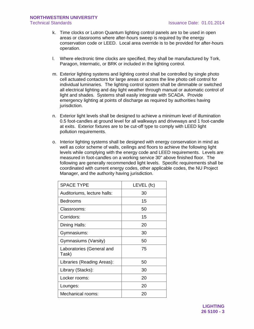
NORTHWESTERN UNIVERSITY Technical Standards Issuance Date: 01.01.2014
LIGHTING 26 5100 - 3
k. Time clocks or Lutron Quantum lighting control panels are to be used in open areas or classrooms where after-hours sweep is required by the energy conservation code or LEED. Local area override is to be provided for after-hours operation.
l. Where electronic time clocks are specified, they shall be manufactured by Tork, Paragon, Intermatic, or BRK or included in the lighting control.
m. Exterior lighting systems and lighting control shall be controlled by single photo cell actuated contactors for large areas or across the line photo cell control for individual luminaries. The lighting control system shall be dimmable or switched all electrical lighting and day light weather through manual or automatic control of light and shades. Systems shall easily integrate with SCADA. Provide emergency lighting at points of discharge as required by authorities having jurisdiction.
n. Exterior light levels shall be designed to achieve a minimum level of illumination 0.5 foot-candles at ground level for all walkways and driveways and 1 foot-candle at exits. Exterior fixtures are to be cut-off type to comply with LEED light pollution requirements.
o. Interior lighting systems shall be designed with energy conservation in mind as well as color scheme of walls, ceilings and floors to achieve the following light levels while complying with the energy code and LEED requirements. Levels are measured in foot-candles on a working service 30" above finished floor. The following are generally recommended light levels. Specific requirements shall be coordinated with current energy codes, other applicable codes, the NU Project Manager, and the authority having jurisdiction.
SPACE TYPE LEVEL (fc)
Auditoriums, lecture halls: 30
Bedrooms 15
Classrooms: 50
Corridors: 15
Dining Halls: 20
Gymnasiums: 30
Gymnasiums (Varsity) 50
Laboratories (General and Task)
75
Libraries (Reading Areas): 50
Library (Stacks): 30
Locker rooms: 20
Lounges: 20
Mechanical rooms: 20
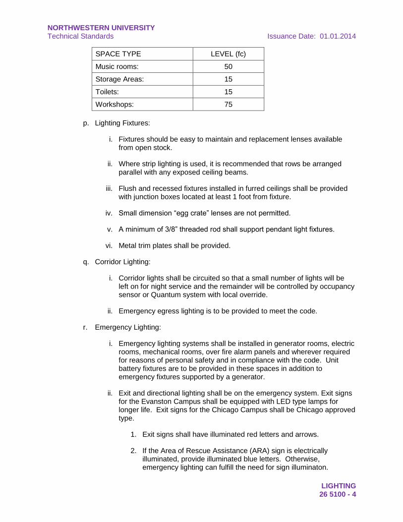
NORTHWESTERN UNIVERSITY Technical Standards Issuance Date: 01.01.2014
LIGHTING 26 5100 - 4
SPACE TYPE LEVEL (fc)
Music rooms: 50
Storage Areas: 15
Toilets: 15
Workshops: 75
p. Lighting Fixtures:
i. Fixtures should be easy to maintain and replacement lenses available from open stock.
ii. Where strip lighting is used, it is recommended that rows be arranged parallel with any exposed ceiling beams.
iii. Flush and recessed fixtures installed in furred ceilings shall be provided with junction boxes located at least 1 foot from fixture.
iv. Small dimension “egg crate” lenses are not permitted.
v. A minimum of 3/8” threaded rod shall support pendant light fixtures.
vi. Metal trim plates shall be provided.
q. Corridor Lighting:
i. Corridor lights shall be circuited so that a small number of lights will be left on for night service and the remainder will be controlled by occupancy sensor or Quantum system with local override.
ii. Emergency egress lighting is to be provided to meet the code.
r. Emergency Lighting:
i. Emergency lighting systems shall be installed in generator rooms, electric rooms, mechanical rooms, over fire alarm panels and wherever required for reasons of personal safety and in compliance with the code. Unit battery fixtures are to be provided in these spaces in addition to emergency fixtures supported by a generator.
ii. Exit and directional lighting shall be on the emergency system. Exit signs for the Evanston Campus shall be equipped with LED type lamps for longer life. Exit signs for the Chicago Campus shall be Chicago approved type.
1. Exit signs shall have illuminated red letters and arrows.
2. If the Area of Rescue Assistance (ARA) sign is electrically illuminated, provide illuminated blue letters. Otherwise, emergency lighting can fulfill the need for sign illuminaton.
NORTHWESTERN UNIVERSITY Technical Standards Issuance Date: 01.01.2014
LIGHTING 26 5100 - 5
iii. Emergency distribution panels shall be located in mechanical and switchboard rooms, accessible only to qualified personnel.
iv. Minimum of 20 foot-candles of lighting is to be provided in mechanical and switchboard rooms. Provide override relay and switch if the mechanical room has more than 10 fixtures on the emergency circuit.
v. Emergency lights are not to be locally switched except in equipment rooms, tunnels and vaults. Emergency lights controlled by the Quantum lighting control system can be switched by that system.
vi. Emergency unit battery lights shall be as manufactured by Surelites.
vii. In buildings where generators and/or life safety equipment exists, the design and construction shall connect to the existing systems.
viii. Emergency unit battery lights shall be designed to be tested as a system per floor.
s. Unfinished Areas:
i. Unfinished areas to have a minimum of 2 foot candles.
ii. Panels and associated feeders for shell spaces will be sized to provide adequate power for maximum future lighting requirements.
END OF SECTION
NORTHWESTERN UNIVERSITY Technical Standards Issuance Date: 01.01.2014
LIGHTING 26 5100 - 6
This page intentionally left blank