Embed Size (px)
Citation preview

1

2
Design Guide & Specification
Residential and Industrial Estates Development
Contact Details:
Darlington Borough Council Paul Ibbertson tel.01325 406711
Hartlepool Borough Council Chris Roberts tel.01429 523254
Middlesbrough Council Michael Mills tel. 01642 728648
Redcar and Cleveland Borough Council Helen Oakes tel.01287 612537
Stockton-on-Tees Borough Council Martin Parker tel.01642 526773
1
Design Guide & Specification
Residential and Industrial Estates Development
DEFINITIONS:
For the purposes of this document the following definitions shall apply:
The Engineers are:
Darlington Borough Council
Dave Winstanley
Assistant Director : Highways & Engineering
Community Services Department
Darlington Borough Council
Town Hall,
Darlington,
DL1 5QT
Hartlepool Borough Council
Alastair Smith
Assistant Director (Transportation and
Engineering)
Neighbourhood Services
Civic Centre
Victoria Road
Hartlepool
TS24 8AY
Middlesbrough Council
David Carter, MSc, MCIHT, CMILT
Head of Transport and Infrastructure
Transport and Infrastructure
Middlesbrough Council
PO Box 504
Civic Centre
Middlesbrough
TS1 9FY
Redcar and Cleveland Borough Council,
Andrew Mollon,
Engineering Manager,
Regeneration Directorate,
Redcar and Cleveland Borough Council,
Redcar and Cleveland House,
Kirkleatham Street,
Redcar,
TS10 1YA
Stockton-on-Tees Borough Council
Richard McGuckin B.Eng., C.Eng., M.I.C.E.
Head of Technical Services
Development and Neighbourhood Services
Stockton-on-Tees Borough Council
PO Box 229
Kingsway House
West Precinct
Billingham
TS23 2YL

i
Design Guide & Specification
Residential and Industrial Estates Development
The Developer is: The party or parties entering into an agreement with the Highway
Authority for the construction of works proposed for adoption under the
Highways Act 1980.
Note: For both design and construction phases of a development, it is
anticipated that responsibility for making day-to-day decisions in relation
to the application of standards laid down in this document will be
delegated by the above parties to appropriately qualified and authorised
engineering staff under their control.
The Developer will normally delegate this responsibility to directly
employed personnel, however, if an external agent is appointed (such as a
consultant or contractor) and the Developer wishes to pursue this party to
have delegated authority, the Engineer must be advised in writing at the
earliest opportunity.

ii
Design Guide & Specification
Residential and Industrial Estates Development
AMENDMENTS
Clause Amendment Date Amended
3.8.3 Drawings to be sent electronically Mar 06
5.4.10 Vehicle Crossing Gradient Mar 06
10.7.1 Quality Assurance Schemes Mar 06
10.7.3 Blast furnace slag included Mar 06
10.7.4 Sasobit included Mar 06
10.8 Clause re-written Mar 06
10.10 Modular blocks reinstatement Mar 06
11.13 Paragraph regarding DNO’s included Mar 06
Major review in line with Manual for July 08
Streets
Section 7 Major Review Dec 08
Section 10 Material Specification Changes Feb 10
Section 13 Major Review Apr 11
Section 14 Revision to 14.5 Furniture Apr 11
5.5.3 Signage to roundabouts Apr 11
Alterations in line with NPPF Feb 13
Shared Access Roads removed Apr15
Section 11 Local variations for Redcar Sept 17
General Updates August 18

iii
Design Guide & Specification
Residential and Industrial Estates Development
LOCAL VARIATIONS
The following represent variations to the text for developments within Darlington Borough
Council only:
(i) In para 2.8 the contact for Secured by Design is the Community Safety Branch,
Durham Constabulary, Police Headquarters, Aykley Heads, Durham, DH1 5TT
(Tel. 0191 3752175)
http://www.durham.police.uk/local/darlington.php
(ii) In para 12.6 carriageway gully pots shall be 450mm internal diameter and 900mm
internal depth.
IN SECTION 11 STREET LIGHTING
The following represent variations to the text for developments within Stockton on Tees
Borough Council only:
Para 3
On completion of painting the column shall be provided with an individual Identification
number as follows:-
Prior to adoption an external identification plate is to be provided at a mounting height of
2.5 metres secured by an agreed fixing mechanism indicating:
Unique column reference
Ownership- Local Authority
Contact information in regards to faults.
Indelible label is to be secured onto the wooden back board inside the column indicating
unique column reference No and column installation date
The following represent variations to the text for developments within Redcar and
Cleveland Borough Council only
11.6 Column protection and identification
All street lighting columns are to be painted; the specification and colour shall be
determined by location, type of road and whether it is in a heritage location. Please contact
the Engineer for details.
All street lighting columns are to have their own unique column reference number, which is
attached to the column by way of a plate using two black tie wraps. Please contact the
Engineer for details.

iv
The lantern shall be flat glass and the lamp, white light. The street lighting design
shall be checked and approved prior to implementation. Please contact the Engineer
for an extensive list of approved equipment.
Before adoption, the Engineer will require sufficient data relating to the street
lighting installation that the PFI provider deems necessary.
Lamp column.
Mallatite Plascoat RAL 6005 Finish 4m – 12m height.
Mallatite Plascoat RAL 6005 passive safety 10m-14m
Abacuss Raise & Lower 5m-10m.
Paint.
Paint Dacraylate RAL6005 Solvent Bourne Acrylic Vinyl Sheen Glass flake.
Black (RAL 9005) Dacrylate Paint Finish for all Heritage Columns.
Cobalt Blue Astral RAL5013 (Dark blue) acrylic vinyl glass flake reinforced sheen finish for the
Coast Roads as identified on the Map Marked Attached.
Lanterns with D55 Regime.
MSD Victorian and embellishment kit Type on Request/Design.
ASD Powder Coated RAL6005 SECTION 38 & 278 Works /All new Designs.
Thorne, ASD all A’ Road replacement works.
Design Plan, Simmonsigns /Subway Lighting.
PEC with 35/18 Regime.
SELC 8480 1 Part Electronic.
SELC 101 TF 1Part Electronic Miniature.
Sign Unit LED.
Reddilight in RAL6005.
Simmonsigns.
Bollards LED with SELC 101.B Infra-Red PEC.
Haldo.
Simmonsigns.
Centre Island Beacons LED.
Signature.
Simmonsigns.
Belisha Beacons LED.
Simmonsigns.
School Crossing Warning Beacons LED.
Simmonsigns.
Isolator.
CED.
Tofco.
No Secondary Isolator Used In Redcar & Cleveland
Section 7 Parking

v
For Stockton please go to www.stockton.gov.uk
It may also be necessary to contact the appropriate Authority to ascertain if there is
any relevant Supplementary Planning Guidance.
Section 11 Street Lighting
For Stockton please go to
www.stockton.gov.uk
Section 12.6 Carriageway Gully Pots
In situ gullies are not allowed in Stockton

6
CONTENTS
INTRODUCTION .................................................................................................................................................... 10
AIMS OF THE DESIGN GUIDE ............................................................................................................................ 11
2.1 INTRODUCTION 11 2.2 EXISTING GUIDANCE 11 2.3 SUSTAINABILITY 11 2.4 SUSTAINABLE DRAINAGE SYSTEMS 11 2.5 ACCESS TO PROPERTIES 12 2.6 DESIGN CONCEPT FOR DEVELOPMENT 12 2.7 INTEGRATION AND PHASING OF NEW DEVELOPMENT 12 2.8 DESIGN SOLUTIONS 12 2.9 SECURED BY DESIGN 12 2.10 ELECTRIC VEHICLE CHARGING POINTS 12
ADOPTION PROCEDURE AND POLICY ............................................................................................................. 13
3.1 GENERAL 13 3.2 PLANNING APPROVALS 13 3.3 ADVANCE PAYMENTS CODE 13 3.4 SECTION 278 AGREEMENTS 14 3.5 SECTION 38 AGREEMENTS 14 3.6 NEW ROADS AND STREET WORKS ACTS 15 3.7 SAFETY AUDIT 16 3.8 SUBMISSION REQUIREMENTS 16 3.9 ISSUING OF CERTIFICATES 19 3.10 MAINTENANCE PERIOD 20 3.11 ADOPTION PROCEDURE 21
STATUTORY REQUIREMENTS............................................................................................................................ 22
4.1 CONSTRUCTION (DESIGN AND MANAGEMENT) REGULATIONS 2007 22 4.2 NEW ROADS AND STREET WORKS ACT 1991 22 4.3 SECTION 104 WATER INDUSTRY ACT 1991 22 4.4 UTILITY APPARATUS IN THE HIGHWAY 23 4.5 DISCHARGE OF HIGHWAY DRAINAGE INTO EXISTING WATERCOURSES 24 4.6 DEPOSITS ON THE HIGHWAY 24 4.7 DIVERSION OF HIGHWAYS OR PUBLIC RIGHTS OF WAY 24 4.8 UNAUTHORISED SIGNS ON THE HIGHWAY 24 4.9 HIGHWAY STRUCTURES 24 4.10 EQUALITY ACT 2010 25
DESIGN GUIDE FOR RESIDENTIAL DEVELOPMENTS ................................................................................... 26
5.1 HIERARCHY OF ROADS 26 5.2 BALANCING PLACE AND MOVEMENT. 27 5.3 HOMEZONES 28 5.4 FOOTWAYS AND FOOTPATHS – GEOMETRY AND CONSTRUCTION STANDARDS 35 5.5 CARRIAGEWAYS – GEOMETRY AND CONSTRUCTION STANDARDS 41 5.6 SHARED SURFACES 56 5.7 STATUTORY UNDERTAKERS APPARATUS 58 5.8 VEHICULAR SERVICING OF COMMERCIAL PREMISES 58
DESIGN GUIDE FOR INDUSTRIAL DEVELOPMENTS ..................................................................................... 59
6.1 HIERARCHY OF ROADS 59 6.2 CARRIAGEWAY – GEOMETRY AND CONSTRUCTION STANDARDS 59

7
6.3 FOOTWAYS AND FOOTPATHS – GEOMETRY AND CONSTRUCTION STANDARDS 60 6.4 PARKING STANDARDS 61 6.5 TRAFFIC CALMING 61 6.6 CYCLING FACILITIES 61 6.7 STREET LIGHTING 61 6.8 HIGHWAY DRAINAGE 61 6.9 HIGHWAY VERGES 61 6.10 STREET NAME PLATES 61 6.11 SIGNING AND ROAD MARKING 62 6.12 PUBLIC SAFETY 62 6.13 STATUTORY UNDERTAKERS APPARATUS 62
DESIGN GUIDE FOR PARKING STANDARDS ................................................................................................... 65
7.1 INTRODUCTION 65 7.2 POLICY CONSIDERATIONS 66 7.3 PARKING STANDARDS 67 7.4 CYCLE PARKING 67 7.5 MOTOR CYCLE PARKING 68 7.6 TRAVEL PLANNING 70 7.7 COMMUTED SUMS 70 7.8 PEOPLE WITH DISABILITIES 71 7.9 DIFFERENTIAL STANDARDS IN CENTRAL AND NON-CENTRAL AREAS 72 7.10 OPERATIONAL AND NON-OPERATIONAL PARKING 73 7.11 FRINGE AREAS 74 7.12 ADOPTION OF PARKING AREAS 74 7.13 SAFER PARKING AWARD (PARK MARK) 75 7.14 TOWN AND COUNTRY PLANNING (USE CLASSES) 75 7.15 DETAILED PARKING STANDARDS 79
DESIGN GUIDE FOR TRAFFIC CALMING ......................................................................................................... 89
8.1 INTRODUCTION 89 8.2 DESIGN REQUIREMENTS 89 8.3 CONSULTATIONS 91 8.4 MEASURES 91
DESIGN GUIDE FOR CYCLE FACILITIES ........................................................................................................ 103
9.1 INTRODUCTION 103 9.2 DEFINITION OF A CYCLE TRACK 103 9.3 LAYOUT 103 9.5 ROAD CROSSINGS 104 9.6 DRAINAGE 104 9.7 EMERGENCY ACCESS 104 9.8 MEASURES TO PREVENT ABUSE BY MOTOR VEHICLES 105 9.9 CYCLE PARKING 105 9.10 DESIGN STANDARDS 105 9.11 STREET FURNITURE AND LANDSCAPING 106 9.12 GENERAL 107
SPECIFICATION FOR ROAD AND FOOTPATH CONSTRUCTION ................................................................. 118
10.1 GENERAL 118 10.2 EARTHWORKS 131 10.3 CARRIAGEWAY CAPPING AND SUB-BASE LAYERS 136 10.4 KERBS, CHANNELS AND EDGINGS 139

8
10.5 DUCTS 143 10.6 CONCRETE 145 10.7 BITUMINOUS MATERIALS 155 10.8 BLOCK PAVING FOR CARRIAGEWAYS 168 10.9 FOOTPATHS, FOOTWAYS AND CYCLETRACKS 172 10.10 REINSTATEMENT 178 10.11 ROAD MARKING 182
DESIGN GUIDE AND SPECIFICATION FOR STREET LIGHTING ................................................................. 183
11.0 STREET LIGHTING 183 11.1 GENERAL 183 11.2 REGULATIONS AND BRITISH STANDARDS 183 11.3 DESIGN REQUIREMENTS 184 11.4 LIGHTING EQUIPMENT ON BUILDINGS 186 11.5 TYPE OF COLUMNS 186 11.6 COLUMN PROTECTION/IDENTIFICATION 187 11.7 ERECTION OF COLUMNS, BRACKET ARMS AND LANTERNS 187 11.8 INTERNAL WIRING OF COLUMNS 189 11.9 TYPE OF LANTERNS 189 11.10 PHOTO ELECTRIC CONTROL (PECU) 189 11.11 FUSED CUT OUTS 189 11.12 UNDERGROUND CABLES 190 11.13 UNDERGROUND CABLE INSTALLATION 190 11.14 ELECTRICITY SUPPLY 190 11.15 COMPLETION OF WORKS 191 11.16 TEST CERTIFICATE 191 11.17 UNDERGROUND CABLE IDENTIFICATION 191 11.18 SKETCHES 191 11.19 STREET FURNITURE – SIGNAGE 191 11.20 DISCONNECTION OR TRANSFER OF STREET FURNITURE 192
DESIGN GUIDE AND SPECIFICATION FOR HIGHWAY DRAINAGE ............................................................ 202
12.1 INTRODUCTION 202 12.2 LOCATION OF HIGHWAY DRAINS 202 12.3 PIPES FOR DRAINAGE 202 12.3 TRENCH EXCAVATION 202 12.4 MANHOLES 206 12.6 CARRIAGEWAY GULLY CONNECTIONS 208 12.7 EXISTING FIELD DRAINS 209 12.8 PROTECTION OF EXISTING WATERCOURSES 211 12.9 OUTFALL TO WATERCOURSES 211 12.10 CCTV SURVEY 211 12.11 OTHER STRUCTURES 211 12.12 OIL SEPARATORS 211
DESIGN GUIDE AND SPECIFICATION FOR HIGHWAY VERGES AND LANDSCAPING ............................ 219
13.1 LANDSCAPING 219 13.2 AREAS FOR ADOPTION 219 13.3 DESIGN REQUIREMENTS 219 13.4 PREPARATION OF FORMATION AND SOILING 220 13.5 EXISTING VEGETATION 221 13.6 DEMOLITIONS 222 13.7 SOILING 222

9
13.8 TOPSOIL 223 13.9 STREET FURNITURE AND MOWING STRIPS 223 13.10 CULTIVATION FOR GRASS SEEDING 224 13.11 GRASS SEED 224 13.12 FIRST CUT 224 13.13 MAINTENANCE – GRASS AREAS 224 13.14 TURFING 225 13.15 PLANTING 225 13.16 TREE AND SHRUB SELECTION 226 13.17 TREES 227 13.18 SHRUBS INCLUDING GRASSES AND HERBACEOUS PLANTS 227 13.19 TREE AND SHRUB PLANTING 228 13.20 BULBS 229 13.21 MAINTENANCE OF PLANTED AREAS AND TREES 229 13.22 ADOPTION PROCEDURE 230 13.23 SUPPLEMENTARY PLANNING DOCUMENTS AND DESIGN GUIDES 230
DESIGN GUIDE AND SPECIFICATION FOR STREET NAMEPLATES AND FURNITURE .......................... 231
14.1 GENERAL 231 14.2 DESIGN 231 14.3 MANUFACTURE 231 14.4 ERECTION 232 14.5 FURNITURE 232 14.6 CLUTTER 235
List of Sketches ..................................................................................................................................................... 236
10
INTRODUCTION 1
INTRODUCTION
1.1 This document has been produced by a working group comprising Engineers and
Planners from the Authorities of Hartlepool, Middlesbrough, Redcar and Cleveland,
Stockton-on-Tees Borough and Darlington Borough Councils.
1.2 Note that throughout this document, for Developer read Developer/Contractor.
1.3 The Guide indicates the minimum standards of the Highway Authority to ensure
adoption under Section 38 of the Highways Act 1980. However, they are not intended
to preclude any requirement for a higher standard that may be deemed necessary by a
Planning Authority. Adherence to the standards set out in the document will ensure
that the Highway Authority is willing to adopt the new highways on completion. When
the application of these standards may be unduly inhibiting due to environmental
factors or other site constraints, the Developer should discuss the possibility of
relaxation of the standards with the Engineer.
1.4. This document is intended to be used by architects, engineers, planners and developers
involved in the preparation of schemes for new development. It is not intended to be a
prescriptive document, although it does set certain standards (as indicated in 1.3 above)
which will normally be required as a condition for adoption of new highways.
It is further intended that new ideas and approaches to design problems should not be
suppressed. Developers and their designers are urged to discuss their ideas with the
Highway/Planning Authority at an early stage in the scheme.
1.5 Developers will find it helpful to establish at the outset the relevant policy context for
any proposed development as set out in the Local Plan for the area. Similarly, the site
may be subject to a development brief, the requirements of which will need to be met.
Any queries relating to this document must be brought to the attention of the
Engineer at the earliest opportunity, and a decision obtained before further work
proceeds

11
AIMS OF THE DESIGN GUIDE 2
2.1 INTRODUCTION
The design of any new development requires care and sensitivity to ensure the highest
possible environmental standards are secured. This guide is intended to assist
developers setting out the basic principles which should be followed in terms of
providing safe, convenient and functionally effective road, footpath and cycle routes,
whilst ensuring that they contribute to the overall attractiveness of the site and it’s
setting.
2.2 EXISTING GUIDANCE
Whilst there are some variations, the standards contained in the guide are generally
based on information contained in the following documents:-
a) Transport in the Urban Environment, June 1997.
b) Manual for Streets (DfT and DCLG).
c) Manual for Streets 2 (CIHT)
In regard to parking and transportation issues, consideration has been given to the
guidance in National Planning Policy Framework
2.3 SUSTAINABILITY
Good design is a key element in achieving the Government’s aim to create thriving,
vibrant, sustainable communities,. It ensures Sustainable Communities that meet the
diverse needs of existing and future residents. Communities that are sensitive to their
environment by minimising their effect on climate change, and contribute to a high
quality of life. They are safe and inclusive, well planned and promote social inclusion,
offering equality of opportunity and good services for all, with good connectivity, so that
the overall layout encourages access by walking or cycling, and shortens the distances
travelled by car.
The One Planet Living initiative, to be found at www.oneplanetliving.org, is a vision of
a sustainable world, in which people everywhere can enjoy a high quality of life within
the productive capacity of the planet.
2.4 SUSTAINABLE DRAINAGE SYSTEMS
The use of SuDS is seen as a primary objective by the Government and should be
applied wherever practical and technically feasible. The developer will be expected,
whether outline or detailed, to demonstrate how a more sustainable approach to
drainage is to be incorporated into the development proposals, and for detailed design
information to be submitted at the appropriate stage. Information on the Tees Valley
Standards for Sustainable Drainage Systems (SuDS) can be found at https://www.middlesbrough.gov.uk/sites/default/files/Tees%20Valley%20Authorities%20local%20standards%20for%20suitable%20drainage.pdf

12
AIMS OF THE DESIGN GUIDE 2
2.5 ACCESS TO PROPERTIES
In planning the layouts of developments, particular attention must be given to affording
ease of access to individual properties (whether by public transport, on foot, by cycle or
by car) and convenient access to community facilities and services. Street networks
should be connected which will lead to easier navigation and a more even spread of
motor traffic.
2.6 DESIGN CONCEPT FOR DEVELOPMENT
Making full and cost effective use of developable land is clearly a desirable planning
objective. However, this must be balanced with regard to ensuring satisfactory design,
use of materials, and the protection and introduction of significant landscape features
to enhance the development. None of these aspects of development should be
considered in isolation but form part of an integrated design approach.
2.7 INTEGRATION AND PHASING OF NEW DEVELOPMENT
The integration of new development into established townscape presents special
challenges. Development of large sites by phasing demands care and consideration.
An overall design concept, with which successive stages of development comply,
should be established at an early stage.
2.8 DESIGN SOLUTIONS
New proposals will, in most circumstances, require to be in sympathy with and
respectful of the character of established development. However, there may be
instances where development can make a positive design statement in its own terms.
2.9 SECURED BY DESIGN
Section 17 of the Crime and Disorder Act 1998, sets a duty on local authorities to
consider crime and disorder implications
The layout of a residential area can have a significant impact on crime against property
(homes and cars) and pedestrians. An effective means of combating crime is at the
initial design and planning stage of new developments and to ensure that crime
prevention considerations are taken into account in the design of layouts, it is
important to consult the Council’s Community Safety Advisor,
It is recommended that developers also take into account Safer Places: The Planning
System and Crime Prevention which is a guide, that will assist in reaching the desired
outcome
2.10 ELECTRIC VEHICLE CHARGING POINTS
As hybrid electric vehicles and battery electric vehicle ownership is expanding, there is
a growing need for widely distributed publicly accessible power points. If a developer
wishes to include a charging point with in the development, discussions with the
relevant Engineer is essential.

13
ADOPTION PROCEDURE AND POLICY 3
3.1 GENERAL
The Highway Authority will adopt highways (to include carriageways, footways, verges,
footpaths and cycleways all incorporating suitable drainage and lighting) maintainable
at public expense, provided that such highways are constructed in accordance with the
standards contained in this document and are subject to an Agreement under Section
38 of the Highways Act 1980.
3.2 PLANNING APPROVALS
The Developer will be required to obtain all necessary outline and full planning
approvals, in connection with all aspects of the development.
It is important for developers to appreciate that obtaining a planning consent does not
imply that a layout is suitable for adoption. It is recommended that the Engineer is
consulted about areas to be adopted at an early stage.
3.3 ADVANCE PAYMENTS CODE
The legislation is dealt with in Sections 219 to 225 of the Highways Act 1980 and was
enacted in order to ensure that when new buildings are constructed, the roads which
service those buildings may be adopted by the Highway Authority without placing a
financial burden either on the Authority or on the owner of the premises then fronting
onto the street.
The advance payment code exists for ensuring that a payment is made, or security is
provided, by a developer to cover the future need to ‘make up’ the street and to enable
frontages to require the adoption of the street, when development has reached a certain
stage.
The procedure to be followed is that the Highway Authority must, within 6 weeks from
the passing of Building Regulation plans, serve a Section 220 Notice on the person on
whose behalf the plans were deposited, requiring the payment or the security under
Section 219, of a sum specified in the Notice.
The sum specified is that which would be recoverable, in respect of the frontage of the
development, if the Authority were to carry out the works required to bring the street
up to a maintainable standard.
Developers can discharge their obligations under the Code by completing a Section 38
Agreement. Even though it may be proposed to complete such an Agreement, it is still
an offence to commence building work (including foundations) before the Agreement is
sealed by both Developer and Bondsman.
A developer who wishes to commence building before the Agreement is sealed should
either;
(a) Obtain a temporary bond from the surety and lodge this with the
Highway Authority.
14
ADOPTION PROCEDURE AND POLICY 3
or (b) Deposit cash with the Highway Authority for those dwellings upon which
it is intended to start work. If the Section 220 Notice specifies the sum or
the whole development, this sum will be broken down upon request, to
identify specific phases of development. Deposits made in this way, will
upon completion of the Agreement, be refunded to the Developer together
with accrued interest.
In respect of any notice served by the Authority, other than one specifying no sum to be
payable, the Developer has the right of appeal to the Minister (Section 220 (6)).
3.4 SECTION 278 AGREEMENTS
Where a development involves works requiring either improvement or alteration to the
existing highway, the Developer may be required to enter into an agreement with the
relevant Council as Highway Authority under Section 278 of the Highways Act 1980
and is in addition to the requirements of a Section 38 Agreement. The Developer is
advised to discuss at the earliest opportunity the requirements for a Section 278
Agreement, since this invariably takes a longer time to process than Section 38
Agreements. This requirement often occurs as a condition on the grant of planning
permission. A Section 278 Agreement, which will need to be supported by a bond,
requires the Developer to pay a sum to the Highway Authority for it to carry out the
necessary improvement works. Where a Section 278 Agreement is required, this must
be signed at the same time as or before the Adoption Agreement under Section 38 is
signed.
3.5 SECTION 38 AGREEMENTS
General
When the Developer wishes to enter into an Agreement under Section 38 Highways Act
1980, written application is to be made to the Engineer, who will prepare the legal
documentation which is to be signed by the Developer, the Surety and the Council and
then sealed.
The Developer should note that the Council’s standard Adoption Agreement is based on
the National Agreement published by the Association of Metropolitan Authorities on
behalf of the Local Authorities Association and the House Builders Federation.
Early consultation with the Highway Authority is recommended to ensure that the
development proposals satisfy the design requirements and will be suitable for
adoption.
When submitting plans to the Engineer for initial consideration 2 copies should be
included, showing the work covered by the Agreement and also draft details of the
various elements of the works.
Recovery of Council’s Costs
(i) The Council incurs cost in carrying out various activities in the course of the
adoption procedure which normally includes technical examination,

15
ADOPTION PROCEDURE AND POLICY 3
processing the Section 38 submission, site inspections and material testing.
These costs will be recovered by charging a fee as follows:
ESTIMATED COST OF
THE WORKS
FEE
up to £10,000 £1000
over £10,000 6% of estimated cost
The estimated cost of the works will be determined by the Council and is
reviewed annually.
(ii) Fees should be paid immediately before the first site inspection or on signing
of the Section 38 Agreement whichever occurs first.
(iii) Legal Fees may be charged in addition and recovered at cost or by a standard
charge, calculated to be non-profit generating, payable on demand.
(iv) Fees have been based upon the assumption that the design submission and the
construction of the works are in general accordance with the recommendations
set out in this Guide. In the event that the submission or that the construction
of the works falls below these standards the Council reserves the right to recover
additional costs incurred in the administration of the Agreement arising from
the rechecking of drawings/calculations and site visits for rechecking sub-
standard work. Additional charges may not be levied for additional costs
relating to changes to the works arising from unforeseeable circumstances (e.g.
adverse ground conditions) but if there is a significant increase in the estimated
cost of the works then a proportional increase in the fee may be made.
3.6 NEW ROADS AND STREET WORKS ACTS
The legislation requires the highway authority to keep a street works gazetteer of all
streets within the highway authority’s area. The developer shall, therefore, supply to
the highway authority such information as required to enable the authority to comply
with the legislation and maintain the street works gazetteer.
The current requirements are:-
The agreed name of the street.
Status of street (prospectively maintainable or private).
Owner of street if private.
Elementary street unit for each street, together with immediate points to enable the
creation of a level 3 gazetteer (see http://www.nsg.org.uk/)
The information shall be provided within four weeks of the street being named or
building work commencing whichever occurs first. Information presented shall be
supported by an O.S. based plan preferably in a digital format.
Any changes during the construction phase which invalidate the information shall

16
ADOPTION PROCEDURE AND POLICY 3
be notified to the engineer within four weeks of the change and revised information
submitted.
3.7 SAFETY AUDIT
Developers should be aware of the Road Safety Audit process.
The purpose of a Road Safety Audit is to identify potential road safety issues of new
highway schemes and improvement schemes that may affect any road user and to
suggest measures to eliminate or mitigate any problems.
Road Safety Audits are intended to ensure that the number and severity of accidents is
kept to a minimum. Auditors identify and address problem areas using the experience
gained from accident reduction schemes, accident investigation and research work and
should be independent of the design team.
All works that involve construction of new highway or permanent change to the existing
highway layout or features should be audited by a minimum of two independent
auditors with appropriate levels of training, skills and experience in Road Safety
Engineering.
A Road Safety Audit should be carried out at the following stages;
Stage 1 Completion of Preliminary Design
Stage 2 Completion of Detailed Design
Stage 3 Completion of Construction
For further reading refer to The Institution of Highways and Transportation Road
Safety Audits HD19/15.
3.8 SUBMISSION REQUIREMENTS
General Information
(i) 2 no. 1:1250 scale plans (1 copy to be a negative) of the proposed development
(including building units) to include OS grid lines for reference (where
practicable).
(ii) 2 no. 1:500 scale plans with contours.
(iii) 2 no 1:500 scale drawings, uncoloured, showing the roads, sewers and proposed
developments (see section 3.6.2 for detailed requirements).
(iv) Name and contact address and telephone number of the Developer and
agent or other employee in charge of the works.
(v) Anticipated date for commencement of the works and the dates for completion to
Part 1 and the whole of the works.
(vi) Programme for the construction of the works.

17
ADOPTION PROCEDURE AND POLICY 3
Detailed Requirements
(i) The relationship of the proposed layout to the existing ground features and
the Ordnance Survey grid (where practicable).
(ii) Carriageways, footways, footpaths, cycle tracks and verges showing widths of
each.
(iii) The location of buildings, plot boundaries and points of pedestrian and
vehicular access to the plots.
(iv) Drainage details including all road, cycle track and footpath gully positions
with connections to the appropriate sewers, including calculations for
highway drainage where appropriate.
(v) Crossfall to carriageways, footways, footpaths, cycle tracks and verges.
(vi) Sight lines at all junctions and all other relevant locations.
(vii) All dimensions of radii and curves to be indicated.
(viii) Centre line to chainages to a change of horizontal and/or vertical alignment.
(ix) The location of proposed ramped footway and cycle track crossings for
pedestrians, cyclists and invalid carriages.
(x) Emergency means of access (where required).
(xi) Residential and visitor parking to be indicated.
(xii) A plan showing all service runs (if available).
(xiii) All street furniture e.g., street lighting, nameplates etc.
(xiv) All areas for proposed adoption by the Highway Authority (ensuring connection
of proposed roads to existing or potentially adoptable highway).
(xv) Traffic calming proposals (where required).
(xvi) The locations of salt bins (where required).
Drawing Submissions
(i) 8 no. drawings to 1:500 scale, with OS grid lines, (where practicable) coloured
to show those works to be covered by the Agreement.
Colouring to be as follows:-
Boundary of the development - Blue
Carriageway - Burnt Sienna
Footways and footpaths - Yellow
18
ADOPTION PROCEDURE AND POLICY 3
Note: Where footpaths cross areas of public open space they are to be
coloured yellow and hatched purple.
Cycle tracks - Orange
Note: Where alteration of an Existing path/track occurs to form a cycle
track, they are to be coloured orange and hatched purple.
Street lighting column positions - Red
Highway Verge - Green
Public Open Spaces - Pink
Highway drains and gully leads from
surface water sewers - Blue
.
Works outside the site boundary carried out as part of the development are to
be bounded by a mauve line.
(ii) 4 no. drawings of longitudinal sections of roads.
Scales to be 1:500 horizontal and 1:50 vertical (depending on topography) and
the drawing should show the following:
(a) Existing ground levels. (b) Proposed road centre line levels and channel levels.
(c) Extent of horizontal and vertical curves.
(d) Centre line chainages.
(e) Highway drainage details including levels, pipe sizes, gradients and
manholes.
(iii) 4 no. drawings of cross sections of 1 to 50 scale and showing the following:-
(a) The profile within the highway boundaries.
(b) The construction of carriageways, footways, cycle tracks, footpaths,
verges and hard standings giving details of the finished thickness and
types of material to be used.
(c) Drainage details.
(iv) 10 no. plans of the development with the areas of public open space within
the development coloured only (where applicable).
(v) Street lighting design to BS 5489 either in the form of isolux lines or spot
light levels.
(vi) 2 no. plans indicating layout of sewers subject to a Section 104 Agreement
(where applicable see Clause 4.3).
19
ADOPTION PROCEDURE AND POLICY 3
Geotechnical Report
A geotechnical report incorporating CBR test results, soil classification (liquid and
plastic limits) and identification of sulphate levels. (See Clause 10.1.1).
3.9 ISSUING OF CERTIFICATES
The Part 1, Part 2 and Part 3 Certificates are eligible to be issued by the Engineer
upon the request of the Developer and on completion of the following:-
Part 1 Certificate
(i) All highway drainage
(ii) Where applicable all other drainage within the highway.
(iii) All kerbs or channels required to retain the carriageway.
(iv) Carriageway to basecourse.
NOTE: The Bond amount will be reduced to 60% upon completion of the above works.
Part 2 Certificate
(i) All kerbs, channels, vehicle crossings and pedestrian ramps.
(ii) The provision of street lighting with electricity supply.
NOTE: At this stage, or prior to with the agreement of the Engineer, upon
Submission of the ET1 and ET2 forms and the completion of any
remedial works, the Council will accept the energy charges and carry
out general routine maintenance works to the street lighting.
(iii) Footway/footpath/cycle track binder course.
(iv) Temporary street nameplates.
(v) Demarcation of sight lines and visibility splays.
NOTE: The bond amount will be reduced to 40% upon completion of the above works.
Part 3 Certificate
(i) Any outstanding kerb and channel work.
(ii) Carriageway surface course (see note c below)
(iii) Footway, footpaths, cycle track surface course.
(iv) Verges and visibility splays.

20
ADOPTION PROCEDURE AND POLICY 3
(v) Street furniture.
(vi) Street nameplates.
(vii) Road markings and signs.
(viii) All other work required by the specification and shown on the drawings.
(ix) Information required by Section 79 and 80 of the New Road and Streetworks
Act 1991 must have been provided. (See Clause 4.2 (ii))
(x) An as built drawing to be provided. The drawing is to record the positions of all
street furniture (Light Columns (with numbers), Street name plates, bollards,
gullies). These drawings to be sent electronically in a .dxf format. If this cannot
be achieved a commuted sum will be required to enable the Authority to carry
out the work in house.
NOTE: (a) The works must connect with other existing adopted highways.
(b) The sewers must have been previously placed on maintenance in accordance
with Section 104 of the Water Industries Act 1991.
(c) The Developer is responsible for carrying out a CCTV survey and undertaking
any remedial works (to the satisfaction of the Engineer) prior to the surface
course being laid including all house connections within the highway limits
(see Clause 4.3).
(d) The Bond will be reduced to 10% of the original amount upon completion
of the above works.
3.10 MAINTENANCE PERIOD
The issue of a Part 3 Certificate will instigate commencement of a 12 month
maintenance period.
It should be noted that the Developer will be responsible for all maintenance aspects
relating to the adoptable works during this maintenance period and until adoption.
Typically maintenance activities could be anticipated in respect of the following:-
(a) road and footpath cleaning
(b) street lighting (lamp faults)
(c) drainage (gully cleaning)
(d) landscaping (grass cutting, shrub pruning, weed removal).
It is the Developers responsibility to request the attendance of the Engineer for the
Final Inspection on completion of the maintenance period.

21
ADOPTION PROCEDURE AND POLICY 3
The Final Inspection should be a joint inspection and the Engineer will require the
following items to have been satisfactorily addressed prior to adopting.
(a) S104 sewer adoption (see Section 4)
(b) The completed Health and Safety file including as constructed plans
(services etc) (see Section 4)
(c) Street lighting certificates (see Section 11)
(d) CCTV of highway drainage (see Section 12)
In addition, any defects or outstanding work items must be resolved to the
Engineers satisfaction prior to adoption.
3.11 ADOPTION PROCEDURE
Following satisfactory completion of the Maintenance Period and issue of the Final
Certificate, the Engineer will process the adoption. The Developer will be advised in
writing of the effective date of adoption and outstanding Bond monies will be released.

22
STATUTORY REQUIREMENTS 4
4.1 CONSTRUCTION (DESIGN AND MANAGEMENT) REGULATIONS 2007
The Developer will be required to carry out the works in compliance with all relevant
Health and Safety Legislation, including the Construction (Design and Management)
Regulations 2007. The Developer is responsible for the preparation of the Health and
Safety File for the project and upon completion of the maintenance period, those aspects
relevant to the highway must be passed on to the Highway Authority.
4.2 NEW ROADS AND STREET WORKS ACT 1991
(i) The Developer should note that when it is necessary to make any connection
or break into any highway outside the site boundary, then the requirements
of the New Roads and Streetworks Act 1991 will apply. A licence will have to
be obtained from the Borough Council and the prescribed fee paid. This
licence and inspection fee is not covered within the payments made under
the Section 38 Agreement.
(ii) The Developer should note that it is a requirement of Section 79 and 80 of the
New Roads and Streetworks Act 1991 that the precise location and depth of all
services including drainage and gully connections are accurately recorded. This
information must be submitted to the relevant authority before the Part 2
certificate (Section 38 Agreement) will be issued.
4.3 SECTION 104 WATER INDUSTRY ACT 1991
Where applicable the Developer will be required to enter into a formal agreement with
the Undertaker (Water Industry) in respect to sewers and pumping stations (in
accordance with Section 104 Water Industry Act 1991).
Clearly, the laying of sewers within the highway limits is of interest to the Highway
Authority, not least of all for the connection of highway drainage. It is essential that
special care is taken to ensure that sewer trenches are correctly backfilled.
Therefore, the Highway Authority requires that the following items must be complied
with.
(i) The Section 38 Agreement will only be signed on certification from the
Water Authority that the Section 104 Agreement has been signed (where
applicable).
(ii) The 12 month maintenance period for highway works (Part 2 Certificate)
will only commence on confirmation that the sewers have been placed on
maintenance in accordance with Section 104 (where applicable).
(iii) The final certificate and subsequent adoption will only occur on
conformation that the sewers have been adopted by the Water Authority

23
STATUTORY REQUIREMENTS 4 .
(iv) Sewer excavations are backfilled in accordance with Clause 10.10
(iv) It is the Developers responsibility to ensure notification of Section 104
approvals etc. to the Engineer.
It should be further noted that it is a requirement of the Highway Authority that the
Developer carries out a CCTV survey of all sewers within the highway, prior to
carriageway surface courses being laid. The purpose of this requirement is to ensure
the adequacy of the sewer system and avoid the need for opening of the highway for
remedial works. This requirement is in addition to the CCTV survey, which will be
organised by the Water Authority, prior to adoption of the sewer systems.
If timed correctly, a single survey could be used to meet both the Highway Authority
and Water Authority requirements, although this must include all highway drainage
and private connections in the Highway.
4.4 UTILITY APPARATUS IN THE HIGHWAY
The Developer will be responsible for ensuring that all utility apparatus required as
part of the development is properly installed prior to the commencement of the
maintenance period. This will involve any apparatus that would normally be provided
by the utility companies for such a development, including cable television etc.
Utility apparatus in areas proposed for adoption by the Highway Authority shall only
be installed on behalf of either Statutory Undertakers or companies appropriately
licensed by the Department of Transport, Local Government and the Regions, thereby
having the same duties and responsibilities as Statutory Undertakers. The developer is
also required to provide the Highway Authority with a comprehensive list of names and
addresses of all those companies the developer intends to use to install such apparatus,
the list to include the SWA Organisational Reference number. This information MUST
be provided before a Part 2 certificate will be issued. Failure to provide such
information may result in the Highway Authority making a declaration under section
87 of the NRSWA 1991.
Utility apparatus proposed for adoption by other bodies or to be retained in the
ownership of the developer or developers Contractor will not normally be granted
authorisation by the Highway Authority. It is important that the rights of access to the
development by utility companies are set out in the management company’s obligations.
The only exception to this is the short lengths which provide a connection from the
Statutory Undertakers Equipment in the abutting highway and which are normally
nominally at right angles to the S.U. Equipment (e.g. sewer connections), where the
relevant Statutory Undertaker would normally require these to be the responsibility of
adjacent property owners.
24
STATUTORY REQUIREMENTS 4
4.5 DISCHARGE OF HIGHWAY DRAINAGE INTO EXISTING WATERCOURSES
All highway drains shall be constructed within the limits of the highway. There is
normally only one exception to this, namely where there is a need for the highway
drainage to discharge into an existing watercourse outside the highway boundary.
In such circumstances, permission must first be obtained from the Environment
Agency or Lead Local Flood Authority prior to any discharge taking place. In
addition, a “Deed of Grant of Easement” will be required from all landowners
through whose land the drainage passes to the watercourse.
The Developer is responsible for obtaining all of the necessary permissions and
consents, prior to signing the Section 38 Agreement.
4.6 DEPOSITS ON THE HIGHWAY
The Developer is responsible for ensuring that all roads, footpaths etc are kept
clean and free from dust, mud slurry and any obstruction. Failure to do this is not
only creating a safety hazard for highway users but would also be an offence under
Section 148 of the Highways Act 1980. Developers should note that both the
Highway Authority and the Police view such an offence as a serious matter and
this could well lead to prosecution.
4.7 DIVERSION OF HIGHWAYS OR PUBLIC RIGHTS OF WAY
Where the diversion of any existing carriageway, footway, footpath, cycleway or
public right of way is required due to the development works, the Developer shall
consult with the Engineer at any early stage to ensure that all necessary legal
procedures for any diversion are implemented.
4.8 UNAUTHORISED SIGNS ON THE HIGHWAY
Unauthorised signs of any description, including routing directions for site traffic
and advertising signs, shall not be erected on the public highways. These illegal
signs will be removed by the Highway Authority and the Developer recharged with
all costs incurred.
4.9 HIGHWAY STRUCTURES
Any proposal that requires the construction of a highway structure (i.e., a retaining
wall or bridge) will require a ‘Technical Approval’, by the Highway Authority, of the
structure regardless of who will be responsible for its future maintenance.
In this respect a document has been produced ‘Technical Approval
Procedure for Developers Structures’ and is available free of charge to
developers from the address at the front of this document.
This procedure should be applied to the designs of all structures with a clear span
or internal diameter greater than 0.9m, retaining walls, within 1.5h (where h is the
retained height of the wall) or 4m of the carriageway, or public footpath, supporting
land above the highway. All retaining walls supporting the highway, or public
footpath, itself and to temporary structures under, over or adjacent to a road

25
STATUTORY REQUIREMENTS 4
carrying public traffic.
This procedure should be applied to proposed structures to which Sections 167 and 176 to 180 inclusive of the Highways Act 1980 are relevant and, where directed by the
Highway Authority to any proposed structure, under, in, adjacent or near to an existing
or proposed highway maintainable at public expense or any other structure providing
access for the public. Such latter structures shall include any tunnels, service culverts,
thrust bores, chambers, manholes and the like proposed by statutory undertakers and
other bodies, also to the assessment of load carrying capacity and whole life cost,
alterations, strengthening and repairs of existing structures to be adopted.
In the case of any doubt, the Highway Authority will decide whether a structure
requires the procedure to be followed.
The Technical Approval Procedures shall be completed before any work commences on
site. A minimum period of 3 months should be allowed between final submission and
approval.
The Highway Authority will make a charge to cover its costs in administering the
Technical Approval Procedure preparing Licences or Agreement required by the
Highways Act and its inspection costs. This charge which will vary according to the
complexity of the design, will be based upon the actual cost incurred and shall be
additional to and independent of the fees chargeable in connection with the Section 38
Agreement.
Any materials testing carried out by the Engineer will be charged separately in addition
to the fees.
A commuted sum will be required to cover the Highway Authority’s additional future
costs in maintaining any structure subject to this Technical Approval Procedure where
it is to be adopted.
All fees due are to be paid to the Highway Authority by the times which it may
stipulate.
4.10 EQUALITY ACT 2010
All developments must comply with the Equality Act 2010. The main provisions of the
Equality Act 2010, which provide the basic framework of protection from
discrimination, victimisation and harassment, came into force from 1 October 2010. The
Act replaces all existing anti-discrimination laws, and extends protection across a
number of ‘protected characteristics’. These are race, gender/sex, disability, age, sexual
orientation, religion or belief, gender reassignment, pregnancy and maternity, and
marriage and civil partnership.

26
DESIGN GUIDE FOR RESIDENTIAL DEVELOPMENTS 5
5.0 RESIDENTIAL DEVELOPMENTS
5.1 HIERARCHY OF ROADS
Introduction
The relationship between the highway hierarchy in the urban and rural road system is
detailed in the following paragraphs.
Strategic Routes (category 2) for fast moving long distance traffic with little frontage
access or pedestrian traffic. Speed limits are usually in excess of 40mph and there are
few junctions. Pedestrian crossings are either segregated or controlled and parked
vehicles are generally prohibited.
Main Distributors (category 3a) are Major Urban Network and Inter-Primary Links
Short medium distance traffic. They are Routes between Strategic Routes and linking
urban centres to the strategic network with limited frontage access. In urban areas
speed limits are usually 40 mph or less, parking is restricted at peak times and there
are positive measures for pedestrian safety.
Secondary Distributor (category 3b) are classified Road (B and C class) and unclassified
urban bus routes carrying local traffic with frontage access and frequent junctions. In
rural areas these roads link the larger villages and HGV generators to the Strategic
and Main Distributor Network. In built up areas these roads have 30 mph speed limits
and very high levels of pedestrian activity with some crossing facilities including zebra
crossings. On-street parking is generally unrestricted except for safety reasons
Link Road (category 4a) are roads linking between the Main and Secondary Distributor
Network with frontage access and frequent junctions. In rural areas these roads link
the smaller villages to the distributor roads. They are of varying width and not always
capable of carrying two way traffic. In urban areas they are residential or industrial
inter-connecting roads with 30 mph speed limits, random pedestrian movements and
uncontrolled parking.
Local Access Road (category 4b) are Roads serving limited numbers of properties
carrying only access traffic. These are all other roads not included above. In rural areas
these roads serve small settlements and provide access to individual properties and
land. They are often only single lane width and unsuitable for HGV’s. In urban areas
they are often residential loop roads, back streets or cul-de-sacs. The recommended
design speed is to be 20mph.
Shared Surface roads, within category 4b, provide vehicular access to no more than 15
dwellings and must not attract through traffic. These roads are distinctive by virtue of
the absence of footways and thus the road surface is jointly used by pedestrian and
vehicular traffic.
Home Zone is the term for a street where people and vehicles share the whole of the
road space safely, and on equal terms. Home Zone streets should have traffic flows of no
more than about 100 vehicles in the afternoon peak hour and the recommended design

27
DESIGN GUIDE FOR RESIDENTIAL DEVELOPMENTS 5
speed is 10mph, which will mean that they are included in the lowest tier of the local
road hierarchy (category 4b). They should be no more than about 400m long.
This distance should be measured from any point within the Home Zone to the nearest
point on a conventional street.
It is recognised that in rural areas and some urban infill sites, it may be difficult or
inappropriate to achieve the requirements specified in the aforementioned hierarchy. It
is recommended in such cases that consultation with the Engineer takes place at an
early stage.
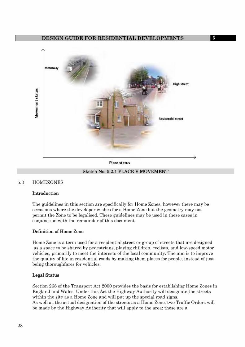
5.2 BALANCING PLACE AND MOVEMENT.
Expressed as a two-dimensional hierarchy, (fig 5.2.1) where the axes are defined in
terms of place and movement. It recognises that, whilst some streets are more
important than others in terms of traffic flow, some are also more important than
others in terms of their place function and deserve to be treated differently. This
approach allows designers to break away from previous approaches to hierarchy,
whereby street designs were only based on traffic considerations. For example:
motorways – high movement function, low place function;
high streets – medium movement function, medium to high place function;
residential streets – low to medium movement function, low to medium place
function.
In new developments, locations with a relatively high place function would be those
where people are likely to gather and interact with each other. Movement and place
considerations are important in determining the appropriate design speeds, speed
limits and road geometry, etc., along with the level of adjacent development and traffic
composition (see Department for Transport Circular 01/2006)
28
DESIGN GUIDE FOR RESIDENTIAL DEVELOPMENTS 5
Sketch No. 5.2.1 PLACE V MOVEMENT
5.3 HOMEZONES
Introduction
The guidelines in this section are specifically for Home Zones, however there may be
occasions where the developer wishes for a Home Zone but the geometry may not
permit the Zone to be legalised. These guidelines may be used in these cases in
conjunction with the remainder of this document.
Definition of Home Zone
Home Zone is a term used for a residential street or group of streets that are designed
as a space to be shared by pedestrians, playing children, cyclists, and low-speed motor
vehicles, primarily to meet the interests of the local community. The aim is to improve
the quality of life in residential roads by making them places for people, instead of just
being thoroughfares for vehicles.
Legal Status
Section 268 of the Transport Act 2000 provides the basis for establishing Home Zones in
England and Wales. Under this Act the Highway Authority will designate the streets
within the site as a Home Zone and will put up the special road signs.
As well as the actual designation of the streets as a Home Zone, two Traffic Orders will
be made by the Highway Authority that will apply to the area; these are a

29
DESIGN GUIDE FOR HOMEZONES 5
A Speed Order and
A Use Order
The ‘Speed Order’ does not change the actual speed limit of the streets, which will be
20mph. However, they do permit the Highway Authority to take steps to keep actual
traffic speeds at a lower level. When traffic is traveling at speeds below 20mph it
becomes safe for pedestrians to share the space with vehicles.
The proposed Speed Order would:
Aim to reduce the speed of motor vehicles to 10 mph within the designated
Home Zone;
Permit the Highway Authority to carry out physical traffic calming to the
adopted streets and generally to promote low driving speeds by residents and
other people in order to achieve this target
The second traffic order, the Use Order, legally permits activities take place on the
public highway in addition to the movement of people and traffic. There is a basic
requirement that no one can obstruct the road, nor deny access to premises.
A use order is an order permitting the use of a road for purposes other than passage.
But a use order may not permit any person;
To wilfully obstruct the lawful use of a road by others, or
to use a road in a way which would deny reasonable access to premises situated
on or adjacent to the road.
Consultations
It will be a requirement for consultations to take place with Disabled organisations,
Police, Fire and Statutory Utilities when designing Home Zones.
As it would prove difficult to consult with the residents in a new build situation it will
be necessary to produce an information pack for all prospective purchasers. This pack
must give general guidelines on Home Zones along with key proposals for the
development.
It must also explain the speed order and the use order. Future purchasers must also be
made aware of the Home Zone guidelines. A pack must also be forwarded to the
Engineer for their agreement.

30
DESIGN GUIDE FOR HOMEZONES 5
Gateway Features
The gateway/entrance to a Home Zone is one of its most important features and it
should be completely distinct in appearance from the surrounding road network.
Entrances and exits of Home Zones must be clearly defined so that all road users
understand the change in the environment and behave accordingly. Design features
such as carriageway narrowing, providing ramps up to the shared surface and textured
carriageway materials must be used as well as other features, including trees and
shrubs and flowers in planters, to create a pleasant gateway feature and help reduce
driver sightlines and vehicle speed.
A Home Zone entrance must incorporate an appropriately positioned statutory Home
Zone sign to give proper indication that the operational nature of the street has
changed.
Diag 881/882
In terms of its geometry the gateway feature must have a radii that will allow both
reasonable access for refuse vehicles and the like whilst being sufficiently small to
ensure that vehicle speeds are very low on entering the Home Zone.
Pedestrian Safe Areas
For reasons of amenity and safety a minimum unobstructed width of 1.5 metres is
required at the edge of the vehicle running track. Over short stretches this width must
increase to 1.8 meters to allow two wheel chairs to pass.
This defined area must be in addition to defensible space in front of dwellings. It must
also be able to be overrun, allowing vehicle access to house plots where necessary.
Opportunities for indiscriminate parking on the defined area must be designed out in
consultation with the Engineer. Some definition and protection of this area, in the form
of changes in surface materials, texture and colour, combined with low hedges / trees
and / or some other appropriately distributed vertical hard or soft landscaping features,
must also be provided.

31
DESIGN GUIDE FOR HOMEZONES 5
Large Vehicles
The ease with which large vehicles can pass through the street should depend upon the
frequency and importance of those events. Refuse vehicles generally visit every week
and the layout should readily accommodate them. Fire tenders and ambulances will
need access only rarely, but adequate access for these vehicles must be maintained. A
large pantechnicon/home removal lorry is a much less frequent visitor, and so the
layout could be designed to require more care and effort from the driver of such a
vehicle.
The ability of the design to allow large vehicles to pass through the proposed Home
Zone layout should be demonstrated, ideally using swept path computer programs.
These simulations should take into account the slow speeds within Home Zones, which
will enable vehicles to make tight radius turns over short distances. It must also be
noted that the minimum carriageway width is 2.75m
Parking
On street parking bays, provided in accordance with Section 7, must be laid out to
minimise their use of public space, complement traffic calming objectives and be
integrated creatively to the Home Zone so they do not dominate the street scene. In
conjunction with landscaping and sharp horizontal deflections in the carriageway,
parking bays must be used to divert the route of vehicles to slow them down. On street
parking bays can be orientated perpendicular, in parallel or in echelon (angled) to the
carriageway alignment. It will also be necessary, at the request of the Engineer, to
provide a swept path analysis to ensure that parking bays can be accessed and exited
safely.
Home Zone design must eliminate opportunities for indiscriminate parking. This can
be achieved by ensuring that such parking is impossible unless it would prevent free
traffic flow and / or vehicular access to house plots and private parking bays / areas.
Length of Zone/Distance from Standard Road
A Home Zone development may consist of several individual "Home Zones" typically
400m (5 mins. walk) to a bus route, although bus routes should not pass through the
Home Zone. Vehicles should not have to travel more than about 400m along Home Zone
streets. This distance should be measured from any point within the Home Zone to the
nearest point on a conventional street.

32
DESIGN GUIDE FOR HOMEZONES 5
Numbers of Dwellings
The number of dwellings within the Home Zone will depend on the number of accesses
leading to the zone, and the size of the dwellings. Home Zone streets should have traffic
flows of no more than about 100 vehicles in the afternoon peak hour. This is usually
the time of day when there is most conflict between vehicles and people, including
children playing. A traffic assessment will have to be carried out to enable the designer
to achieve this target.
Street Furniture/Landscaping
The extent and type of street furniture used in a new build Home Zone should be part of
a coordinated approach promoting a common theme and sense of identity. Furniture
must be agreed with the relevant officer during the design stage. Furthermore it should
take account of the following issues: -.
The choice of street furniture needs to be fit for the intended purpose to avoid
unnecessary and costly maintenance. It will also need to be aesthetically
pleasing and practical to use and where appropriate add to the opportunity for
informal play. Street furniture and traffic calming should be designed with play
and informal seating in mind, such as low walls.
Where pavement bollards are used they should fit with the general theme of the
home zone, be of robust construction and high quality finish. Concrete bollards
should be avoided.
A well thought out planting schedule for the new build Home Zone can have a
dramatic effect on the finished scheme and can perhaps do more than any other
feature to blend the distinction from identified carriageway/footway towards a
more shared environment. Care must be taken to ensure that this area of work
is not seen merely as an ‘add on’ but rather undertaken as an integral part of the
whole design.
When considering the whole planting regime within a new build Home Zone provision
must be made for the care and maintenance of plants and trees post completion of the
development. It must also be taken into account the mature situation of any planting
that it does not impede any other requirements.
Street furniture should only be provided where it is necessary. Its positioning should be
logical and it should always act as an integral part of the overall design. The potential
for street furniture to present a tripping or collision hazard will be lessened
if it is logically placed;
extends at least 1m above surface level
is positioned such that any horizontal elements do not project into circulation
routes (i.e. the horizontal section of a seat);
has its position identified by surface level visual contrast or a tactile area;
contrasts visually against the background against which it will be viewed in both
natural daylight and artificially lit situations.

33
DESIGN GUIDE FOR HOMEZONES 5
Materials and Commuted Sums
The scope of materials will be durable, well established, and readily available and will
still be available when future maintenance obligations dictate. As sustainability is also
a key issue approved recycled materials will also be looked upon favourably
With careful consideration of these factors and the active involvement of a well
balanced development team it should be possible to create a materials schedule that
both reflects the message "Home Zone" whilst still being practical and relatively easy to
construct and maintain.
The developer must submit for approval by the relevant Engineer a list of all suppliers
of materials and furniture and must indicate how replacements or alternative features /
materials can be obtained for future maintenance needs.
The relevant Engineer will also require a commuted sum for the maintenance of
materials, street furniture, artwork and landscaping
Disability Equality Duty
Mobility within the street environment will present different issues for people with
different disabilities. the term 'disabled people' refers to the current generally
recognised inclusion of people with a physical, sensory or mental impairment.
Whilst the concept of a Home Zone is one of a shared area that incorporates little or no
use of hard physical features to delineate space, the areas that represent the most likely
routes to be used, or followed, by vehicles and pedestrians should be identifiable to all
users of the area.
Whether this is done by providing information –
to delineate space and activity at surface level using, for example,
visual contrast - although this will not be of benefit blind people with no
remaining vision;
by physical features at ground level using, for example, tactile surface finishes;
by intermittent physical features above surface level using, for example,
bollards, trees, lampposts, and individual seats; or,
by continuous physical features above surface level using, for example, rows of
seating, and railings.
It is important for all users that they can identify any likely or preferred uses for
different areas within the Zone, and that any methods used to do that are clear,
unambiguous, and do not unduly restrict general freedom of movement.
Identifiable pedestrian pathways will benefit disabled users, but careful attention is
needed in the design of the Home Zone to the provision and sighting of appropriate
crossing points.

34
DESIGN GUIDE FOR HOMEZONES 5
Traffic Calming
In Home Zones short forward visibility standards must be applied to discourage high
vehicle speed. As a general guide forward visibility should not significantly exceed 30
metres. Occasional horizontal deflections in the vehicle track, when combined with
careful positioning of hard and soft landscaping, such as trees, dwellings and other
appropriate structures, can be used to reduce sightlines and help slow vehicle speed. To
be effective such horizontal running track deflection should be severe and the length of
the displacement short. Best practice suggests such deflections should be positioned
every 30 metres to achieve the target speed of 10 mph.
Utilities.
It is best to liase with the utility companies when the layouts of the buildings and
streets are being designed. In nearly all cases this should be prior to making the
planning application. The requirements for new apparatus should be taken into account
in the layout and design of the streets, and a balance should be struck between the
requirements of the utility companies and other objectives. The locations of any existing
trees or shrubs, and proposals for new planting, will require special consideration.
As some stretches of carriageway may be only one vehicle width it may be necessary to
ensure that there is an alternative vehicle route in case of utility works in these
locations, or if this is not possible to avoid placing apparatus in these locations.
To protect utility services from potential damage the developer will need to avail
himself of the various clearance requirements required by the public utility services.
Further Guidance
Further guidance can be found at a number of locations including;
www.homezones.org
www.dft.gov.uk/pgr/sustainable/homezones

35
FOOTWAYS AND FOOTPATHS – GEOMETRY & CONSTRUCTION
STANDARDS
5
5.4 FOOTWAYS AND FOOTPATHS – GEOMETRY AND CONSTRUCTION STANDARDS
Definitions
A “Footway” is generally adjacent to a carriageway and over which the public have a
right of way on foot only.
A “Footpath” is generally remote from a carriageway and over which the public have a
right of way on foot only.
Requirements
All works that involve construction of new highway or permanent change to the existing
highway layout or features should be audited by a minimum of two independent
auditors with appropriate levels of training, skills and experience in Road Safety
Engineering.
When designing for pedestrians (or cyclists), some requirements are common to both:
routes should form a coherent network linking trip origins and key destinations,
and they should be at a scale appropriate to the users;
in general, networks should allow people to go where they want, unimpeded by
street furniture, and other obstructions or barriers;
Where it is necessary to break a road link in order to discourage through traffic, it is
recommended that connectivity for pedestrians is maintained through the break unless
there are compelling reasons to prevent it.
Sightlines and visibility towards destinations or intermediate points are important for
pedestrian way-finding and personal security, and they can help people with cognitive
impairment.
Pedestrian desire lines should be kept as straight as possible at side-road junctions
unless site-specific reasons preclude it. Small corner radii minimise the need for
pedestrians to deviate from their desire line
At junctions and other locations, such as school or community building entrances, there
are benefits in considering bringing the carriageway up flush with the footway to allow
people to cross on one level, this can be achieved by:
raising the carriageway to footway level across the mouths of side roads;
providing a full raised speed-table at ‘T’ junctions and crossroads
Disability Requirements
For the purposes of this design guide, pedestrians include wheelchair users and people
pushing wheeled equipment such as prams.

36
FOOTWAYS AND FOOTPATHS – GEOMETRY & CONSTRUCTION
STANDARDS
5
As pedestrians include people of all ages, sizes and abilities, the design of streets needs
to satisfy a wide range of requirements. A street design which accommodates the needs
of children and disabled people is likely to suit most, if not all, user types.
Not all disability relates to difficulties with mobility. People with sensory or cognitive
impairment are often less obviously disabled, so it is important to ensure that their
needs are not overlooked. Legible design, i.e. design which makes it easier for people to
work out where they are and where they are going, is especially helpful to disabled
people.
Obstructions on the footway should be minimised. Street furniture is typically sited on
footways and can be a hazard for blind or partially-sighted people.
Dropped kerbs with the appropriate tactile paving should be provided at all side-road
junctions where the carriageway and footway are at different levels.
They should not be placed on curved sections of kerbing because this makes it difficult
for blind or partially sighted people to orientate themselves before crossing, unless
there is no suitable alternative.
Footway and Footpath Widths
There is no maximum width stipulated for a footway however 2m is the minimum width
and this should be measured between restraints. Footways must be provided on both
sides of the carriageway unless it is a single sided development where a 2m highway
verge may be provided in lieu of the footway fronting the open area. Independent
footpaths are to be a minimum of 1.5m wide measured between restraints.
Additional widths will be required outside shopping centres, schools, etc where people
congregate and adjacent to heavily trafficked carriageways.
Crossfalls and Gradients
The maximum longitudinal gradient of footways and footpaths should be 5% (1 in 20)
although this may be increased to 8% (1 in 12) subject to the approval of the Engineer.
Further guidance can be found in the Inclusive Mobility guide to best practice on /access
too pedestrian and transport infrastructure
Footpath drainage should be introduced where flows of surface water are liable to cause
problems to adjacent areas. This footpath drainage is to be provided to the satisfaction
of the Engineer. Footpath crossfall should be 2.5% to 4.0% (1 in 40 to 1 to 25).
Emergency Access
To allow for the passage of emergency vehicles when it is located within the footpath
the sub base thickness shall be increased to 250mm. Within areas of public open space
a 250mm layer of sub base shall be laid 100mm below finished ground level or
alternatively with the approval of the Engineer a proprietary method of reinforcement

37
FOOTWAYS AND FOOTPATHS – GEOMETRY & CONSTRUCTION
STANDARDS
5
may be used, i.e., grasscrete or netlon. Collapsible or removable bollards or fencing,
with the agreement of the Engineer, should be provided at both ends of the access to
prevent unauthorised vehicle access.
Ramps and Steps
Ramps for prams and wheel chairs must be provided as an alternative route where the
use of steps is unavoidable. Handrails should be provided to at least one side of a flight
of steps or ramps. Barriers or posts should be introduced to deter misuse.
Pedestrian Crossing Points
The specific conditions in a street will determine what form of crossing is most relevant.
All crossings should be provided with tactile paving. Further advice on the assessment
and design of pedestrian crossings is contained in Local Transport Notes1/95 and 2/95
and the Puffin Good Practice Guide.
Surface level crossings can be of a number of types, as outlined below:
Uncontrolled crossings – these can be created by dropping kerbs at intervals
along a link. As with other types of crossing, these should be matched to the
pedestrian desire lines. If the crossing pattern is fairly random and there is an
appreciable amount of pedestrian activity, a minimum frequency of 100 m is
recommended.
Informal crossings – these can be created through careful use of paving
materials and street furniture to indicate a crossing place which encourages
slow-moving traffic to give way to pedestrians.
Pedestrian refuges and kerb build-outs– these can be used separately or in
combination. They effectively narrow the carriageway and so reduce the crossing
distance. However, they can create pinch-points for cyclists if the remaining gap
is still wide enough for motor vehicles to squeeze past them.
Zebra crossings – of the formal crossing types, these involve the minimum delay
for pedestrians when used in the right situation.
Where pedestrian refuges and kerb build-outs are used adequate signage /markings and
lighting should be provided to warn vehicles of these.
Care must be taken not to site pedestrian crossing points at gully locations.
Footway and Footpath Construction
The footways and footpaths shall be of flexible construction constructed in accordance
with Section 10.9 of the Specification unless otherwise directed by the Engineer.

38
FOOTWAYS AND FOOTPATHS – GEOMETRY & CONSTRUCTION
STANDARDS
5
Tactile Paving
Dropped kerbs shall be introduced at all pedestrian crossings and should be marked
with appropriate tactile paving and aligned with those on the other side of the
carriageway. (See Sketch 5.4.1). however tactile paving is required at crossing points
regardless of whether kerbs are dropped or the carriageway is raised to footway level.
The paving shall be red at controlled crossing points and buff at uncontrolled.
In locations where footpaths cross over cycleways, the layout must be so designed as to
give priority to the continuity of the footpath.
Vehicular Crossings
Vehicular crossings should be provided to all properties having incurtilage parking
facilities. The crossing shall be a minimum of 2.7m wide with a transition kerb at
either side and should be constructed in accordance with Clause 10.9.6. The width of
the crossing should be increased in line with the width of the drive, to a maximum of
5m, or if the access is not at right angles to the road.
The normal footway cross-fall should be maintained as far as practicable from the back
of the footway (900 mm minimum).
Vehicle crossovers are not suitable as pedestrian crossing points. Blind or partially
sighted people need to be able to distinguish between them and places where it is safe
to cross. Vehicle crossovers should therefore have a minimum up stand of 25 mm at the
carriageway edge. Where there is a need for a pedestrian crossing point, it should be
constructed separately, with tactile paving and kerbs dropped flush with the
carriageway.
Footway and Footpath Construction
The footways and footpaths shall be of flexible construction constructed in accordance
with Section 10.9 of the Specification unless otherwise directed by the Engineer.

39
FOOTWAYS AND FOOTPATHS – GEOMETRY & CONSTRUCTION
STANDARDS
5
3. The use of tactile paving shall be in accordance with the recommendation given in 'Guidance on the use of Tactile Paving Surfaces' published by DETR
2. Crossing points to be laid directly apposite each other with domes aligned in the direction of the crossing.
NOTES
1. Tactile paving, coloured buff shall be used at pedestrian crossing points to identify the existence of a dropped kerb and an appropriate place to cross.
MID-BLOCK UNCONTROLLED CROSSING
TACTILE PAVING
TACTILE PAVING
0.9M
1.8
M DROPPED
KERB
CA
RR
IAG
EW
AY
DROPPED KERB
FO
OT
WA
Y
UNCONTROLLED CROSSING POINT AT SIDE ROAD
IN-LINE UNCONTROLLED CROSSING
DROPPED KERB
DROPPED KERB
0.45M 1.8
M
2m
TACTILE PAVING
DROPPED KERB
TANGENT POINT
1.35M MIN.
DROPPED KERB FOOTWAY
CARRIAGEWAY
Sketch No. 5.4.1 TYPICAL EXAMPLE OF PEDESTRIAN CROSSING POINT
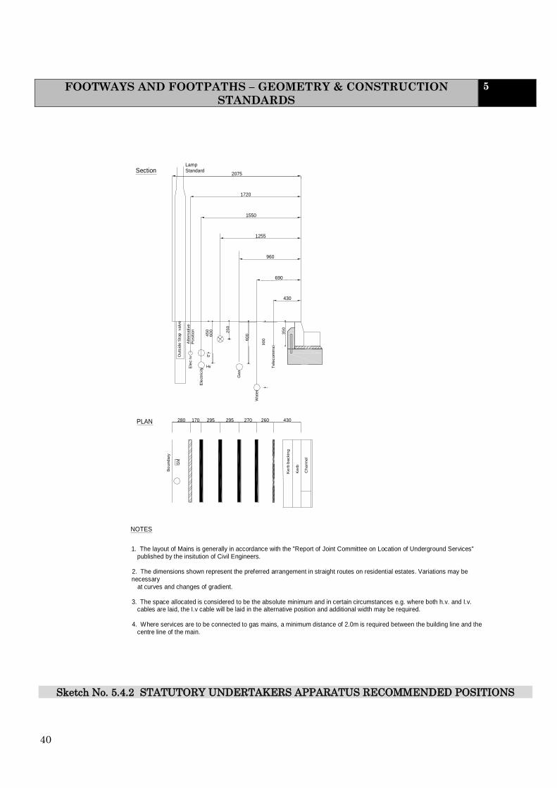
40
FOOTWAYS AND FOOTPATHS – GEOMETRY & CONSTRUCTION
STANDARDS
5
1. The layout of Mains is generally in accordance with the "Report of Joint Committee on Location of Underground Services" published by the insitution of Civil Engineers.
2. The dimensions shown represent the preferred arrangement in straight routes on residential estates. Variations may be necessary at curves and changes of gradient.
3. The space allocated is considered to be the absolute minimum and in certain circumstances e.g. where both h.v. and I.v. cables are laid, the I.v cable will be laid in the alternative position and additional width may be required.
4. Where services are to be connected to gas mains, a minimum distance of 2.0m is required between the building line and the centre line of the main.
295
1255
1550
1720
2075
NOTES
Bo
und
ary
SV
Ou
tsid
e S
top
va
lve
Po
sitio
n
Alte
rna
tive
PLAN
Ele
ctr
icity
170 280 295
Ele
c I
v
Hv Iv
45
0
60
0
25
0
Section Lamp Standard
Ke
rb b
ackin
g
Ch
ann
el
Ke
rb
430 260 270
Wa
ter
Ga
s
60
0
Te
lecom
ms 9
00 3
50
430
690
960
Sketch No. 5.4.2 STATUTORY UNDERTAKERS APPARATUS RECOMMENDED POSITIONS

41
CARRIAGEWAYS – GEOMETRY AND CONSTRUCTION STANDARDS 5
5.5 CARRIAGEWAYS – GEOMETRY AND CONSTRUCTION STANDARDS
Introduction
The following standards apply to secondary distributor roads, and categories below this,
since higher road categories are seldom the concern of a private developer. Therefore,
the standards relate to the types of carriageway required at the local (district) level.
For the design of higher categories the advice of the Highway Authority should be
sought at an early stage.
Appendix 5.5 provides a detailed summary of the design standards associated with
Category 3b to 4b roads.
The Engineer must be consulted at the initial layout stage to consider the likelihood of
bus services penetrating the development and to indicate possible routes. Bus lay-bys
should be in accordance with Sketch 5.5.4. Low floor bus kerbs are to be used, following
consultation with the relevant Engineer, at all bus stops
Junctions
The design of new junctions with the strategic route and main distributor network
shall be determined by the Engineer.
Junctions of any roads with a secondary distributor road (category 3b) and strategic
road (category 2) should be a desirable minimum distance of 90m and 60m apart
respectively, where roads are located on one side of the major road. All junctions for
these categories of roads should be of the ‘T’ type with the angle as close to 900 as
possible
Where roads are in the higher place status, mainly category 4a and 4b roads, a
broader range of junction geometries can be used as shown in Figure 5.5.1. However
Cross/staggered, Multi armed, Square, Circus and Crescent should only be used on
category 4b roads. The basic junction forms should be determined at the master
planning stage.
At the street design stage, they will have to be considered in more detail in order
to determine how they are going to work in practice. To substantiate the use of the
junction evidence of performance will need to be submitted to the Engineer. The
detailed design will cover issues such as materials, traffic priority arrangements, the
need, or otherwise, for signs, markings and kerbs.
Mini-roundabouts and shared surface squares can be incorporated within some of the
depicted arrangements.

42
CARRIAGEWAYS – GEOMETRY AND CONSTRUCTION STANDARDS 5
Sketch No. 5.5.1 ILLUSTRATIVE JUNCTION LAYOUTS
Junction design should facilitate direct pedestrian desire lines, and this will often mean
using small corner radii.
All road junction gradients shall be a maximum of 5% over the extent of the bellmouth.
Roundabouts
Should the Developer propose to include a roundabout on the road layout, consultation
should take place with the Engineer at an early stage. The design is required to comply
with DfT notes for guidance TD54/07 and TD16/07.
In addition, signage in accordance with The Traffic Signs Regulations and General
Directions 2002 and the Traffic Signs Manual will be required.
Carriageway Width
Carriageway widths should be appropriate for the particular context and uses of the
street.
Key factors to take into account include:
the volume of vehicular traffic and pedestrian activity;
the traffic composition;
the demarcation, if any, between carriageway and footway (e.g. kerb, street
furniture or trees and planting);
Regular
Irregular
Nodal Form T Y Cross/
Staggerd
Mutli
Armed
Square Circus Cresent
Illustrative junction layouts

43
CARRIAGEWAYS – GEOMETRY AND CONSTRUCTION STANDARDS 5
whether parking is to take place in the carriageway and, if so, its distribution,
arrangement, the frequency of occupation, and the likely level of parking
enforcement (if any);
the design speed (recommended to be 20 mph or less in residential areas);
the curvature of the street (bends require greater width to accommodate the
swept path of larger vehicles); and
any intention to include one-way streets, or short stretches of single lane
working in two-way streets.
Appendix 5.5 gives guidance on carriageway widths. However, early consultation is
recommended with the Engineer, as the carriageway widths will require examining in
context with the full layout . It is also possible that a higher standard may be necessary
to cater for future development.
When a road may become a bus route the carriageway shall be not less than 6.7m in
width. In cases where the road may be of major importance (e.g., servicing shopping,
business and community centres or future development) the Engineer may require a
carriageway of 7.3m width.
Swept Path Analysis
Swept path analysis, or tracking, will be required to determine the space required for
various vehicles. It will also ensure that the junctions are negotiable by vehicles
Drawings to be forwarded to the Engineer to assist in checking the scheme.
Design Speeds
Design speeds shall be in accordance with the standards shown in Appendix 5.5.
Visibility Requirements
Any land falling within a visibility splay must be included in the Section 38
Agreement and become part of the adopted highway.
To enable drivers to see a potential hazard in time to slow down or stop comfortably
before reaching it, it is necessary to consider the drivers line of vision, in both the
vertical and horizontal planes, and the stopping distance of the vehicle.
The eye level of drivers can vary from 1.05m above the carriageway in a standard car to
approximately 2m in commercial vehicles. To enable drivers to see each other across
summits, across bends and at junctions, unobstructed visibility will be required at least
between these heights above the carriageway.
However, for drivers to see and be seen by pedestrians, particularly child pedestrians
and wheelchair users unobstructed visibility will be required to a point closer to the
ground. The height of a very young child of walking age is around 780mm, but the
height of a child on a tricycle can be even lower.

44
CARRIAGEWAYS – GEOMETRY AND CONSTRUCTION
STANDARDS
5
As general guidance, it is suggested that a height of 600mm be taken as the point above
which unobstructed visibility should be provided wherever the potential exists for
conflicts between motorists and young children. The most obvious obstructions to
visibility are summits, adjacent buildings (including bus shelters), screen walls, densely
planted trees, and parked cars.
Shrubs and trees may be planted in visibility splays at junctions and on bends, provided
when mature they do not obscure horizontal sight lines and there will continue to be
clear vision between heights of 600mm and 2m above ground level. Generally the aim
should be to ensure good visibility without having to rely on frequent maintenance.
Stopping distances
The horizontal distance over which unobstructed visibility should be maintained will
depend upon the stopping distance of vehicles as shown in Table 5.5.1. This in turn will
depend upon vehicle speeds, deceleration rates, gradients and drivers reaction times.
The distances are intended to cater for the majority of vehicles and drivers in most
weather conditions and may therefore safely be used as guidance in the design of the
residential road network.
TABLE 5.5.1 STOPPING DISTANCES
DESIGN SPEED km/h mph
ROAD CATEGORY
MINIMUM STOPPING DISTANCE (m)
60 40 3a 59
48 30 3b 43
48 30 4a 43
32 20 4b 25
16 10 Home Zone 11

45
CARRIAGEWAYS – GEOMETRY AND CONSTRUCTION STANDARDS 5
Possible feature preventing vehicles from crossing the centre line
Alternative left-hand visibility splays if vehicles approaching from the left are unable to cross centre line
Y distance Y distance
Left-hand visibility splay
Right-hand visibility splay
X distance
Y distance Y distance
X distance
Visibility splay
Tangent to kerb line (additional check)
Tangent to kerb line (additional check)
Possible feature preventing vehicles from crossing the centre line
Alternative left-hand visibility splays if vehicles approaching from the left are unable to cross centre line
Sketch No. 5.5.2 VISIBILITY AT JUNCTIONS
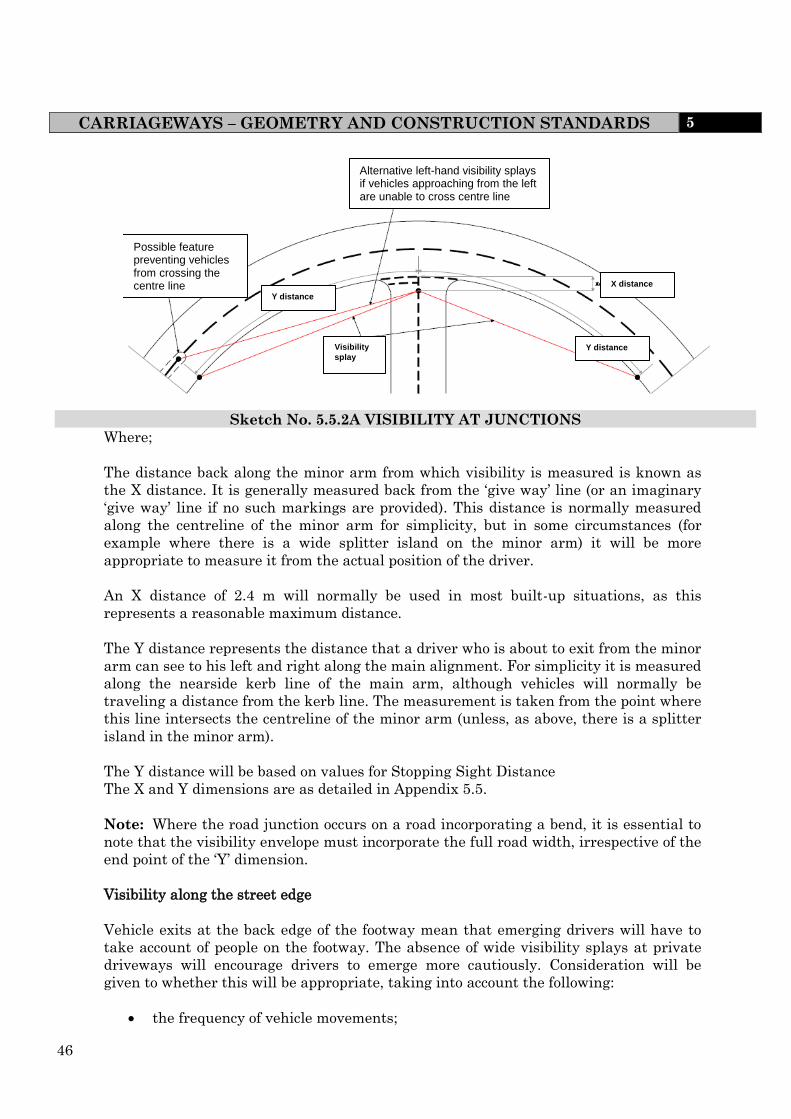
46
CARRIAGEWAYS – GEOMETRY AND CONSTRUCTION STANDARDS 5
Alternative left-hand visibility splays if vehicles approaching from the left are unable to cross centre line
Possible feature preventing vehicles from crossing the centre line
Y distance
Y distance
X distance
Visibility
splay
Sketch No. 5.5.2A VISIBILITY AT JUNCTIONS
Where;
The distance back along the minor arm from which visibility is measured is known as
the X distance. It is generally measured back from the ‘give way’ line (or an imaginary
‘give way’ line if no such markings are provided). This distance is normally measured
along the centreline of the minor arm for simplicity, but in some circumstances (for
example where there is a wide splitter island on the minor arm) it will be more
appropriate to measure it from the actual position of the driver.
An X distance of 2.4 m will normally be used in most built-up situations, as this
represents a reasonable maximum distance.
The Y distance represents the distance that a driver who is about to exit from the minor
arm can see to his left and right along the main alignment. For simplicity it is measured
along the nearside kerb line of the main arm, although vehicles will normally be
traveling a distance from the kerb line. The measurement is taken from the point where
this line intersects the centreline of the minor arm (unless, as above, there is a splitter
island in the minor arm).
The Y distance will be based on values for Stopping Sight Distance
The X and Y dimensions are as detailed in Appendix 5.5.
Note: Where the road junction occurs on a road incorporating a bend, it is essential to
note that the visibility envelope must incorporate the full road width, irrespective of the
end point of the ‘Y’ dimension.
Visibility along the street edge
Vehicle exits at the back edge of the footway mean that emerging drivers will have to
take account of people on the footway. The absence of wide visibility splays at private
driveways will encourage drivers to emerge more cautiously. Consideration will be
given to whether this will be appropriate, taking into account the following:
the frequency of vehicle movements;

47
CARRIAGEWAYS – GEOMETRY AND CONSTRUCTION STANDARDS 5
the amount of pedestrian activity; and
the width of the footway.
On Bends
Forward visibility curves on bends should be constructed in accordance with the
procedure set out below and as indicated in Sketch 5.5.3.
i. a line should be drawn parallel to the inside kerb, centreline of the inner traffic
lane to represent the path of the vehicle.
ii. the required stopping distance commensurate with the desired road speed should
be ascertained and measured back along the vehicle path from tangent point A;
iii. the stopping distance should then be divided into equal increments of
approximately 3m, and the increment points numbered in sequence;
iv. the same stopping distance with the same number of increments should then
be repeated around the curve, finishing at a full stopping distance beyond the
tangent point B;
v. the area which has to be kept clear of obstruction should then be constructed by
joining increments of the same number together i.e., 1 to 1, 2 to 2 etc.
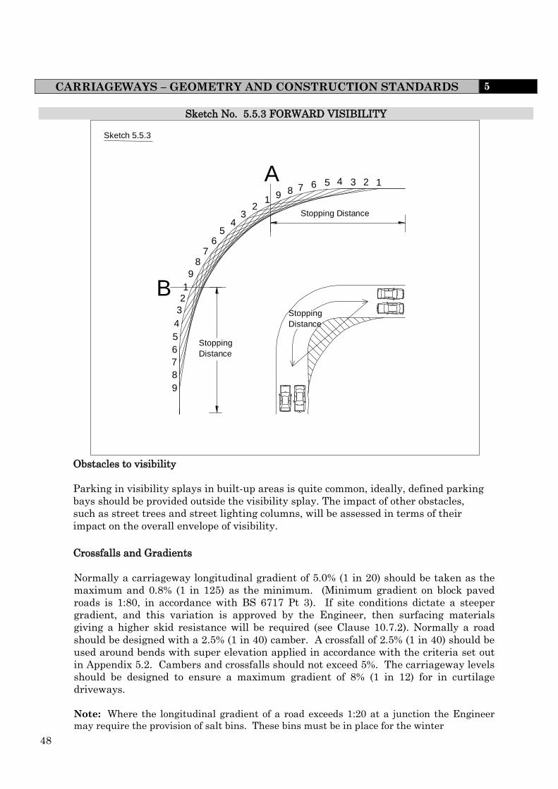
48
CARRIAGEWAYS – GEOMETRY AND CONSTRUCTION STANDARDS 5
Sketch No. 5.5.3 FORWARD VISIBILITY
9 8 7 6 5 4 3 2 1 9
8 7
6
4 3
5
2 1 9 8 7 6 5 4 3 2 1
B
A
Sketch 5.5.3
Stopping Distance
Stopping Distance
Stopping Distance
Obstacles to visibility
Parking in visibility splays in built-up areas is quite common, ideally, defined parking
bays should be provided outside the visibility splay. The impact of other obstacles,
such as street trees and street lighting columns, will be assessed in terms of their
impact on the overall envelope of visibility.
Crossfalls and Gradients
Normally a carriageway longitudinal gradient of 5.0% (1 in 20) should be taken as the
maximum and 0.8% (1 in 125) as the minimum. (Minimum gradient on block paved
roads is 1:80, in accordance with BS 6717 Pt 3). If site conditions dictate a steeper
gradient, and this variation is approved by the Engineer, then surfacing materials
giving a higher skid resistance will be required (see Clause 10.7.2). Normally a road
should be designed with a 2.5% (1 in 40) camber. A crossfall of 2.5% (1 in 40) should be
used around bends with super elevation applied in accordance with the criteria set out
in Appendix 5.2. Cambers and crossfalls should not exceed 5%. The carriageway levels
should be designed to ensure a maximum gradient of 8% (1 in 12) for in curtilage
driveways.
Note: Where the longitudinal gradient of a road exceeds 1:20 at a junction the Engineer
may require the provision of salt bins. These bins must be in place for the winter
49
CARRIAGEWAYS – GEOMETRY AND CONSTRUCTION STANDARDS 5
maintenance season (October to April), in a location to be agreed with the Engineer,
and be maintained and regularly filled by the Developer during this period up until the
adoption of the highway.
Vertical Curves
Vertical curves shall be provided at all changes in gradient and be designed so that the
safe stopping distance given in Appendix 5.5 is provided. This distance is measured
along the centre line of both traffic lanes between points 2m above the road in the case
of Category 3b and 4a roads and 2m and 0.6m in both directions in the case of
Categories 4b roads.
Horizontal Curves
Horizontal curves shall be designed in accordance with Appendix 5.5 which gives the
minimum centre line radii of the carriageway together with any super elevation
requirement.
However, for 4.8m roads with centre line radii of 20m and less, a swept path analysis
must be submitted clearly demonstrating the passage of a car and refuse size vehicle at
the same time.
Vehicle Turning Facilities
Where it is necessary to provide facilities for a vehicle to turn around a swept path
analysis should be carried out to determine how the vehicle could be accommodated.
Whilst adequate parking will be provided in other areas of the development it is
anticipated that the public will still park in these areas and this should be taken into
consideration within the design.
Sketch no. 5.5.5 shows an example of the shapes that can be used.
If the length of a cul-de-sac exceeds 180m then an additional side turning bay should be
provided.
Vehicular Access to Property
The following standards shall apply: -
(i) A limit of one access per property wherever possible, but where a double
garage/vehicle hard standing is provided the vehicle crossing must be
widened accordingly. The access width shall be a minimum of 2.7m wide
and a recommended maximum width of 5m.
(ii) The access should be at 90 to the centre line of the road.
(iii) In the interest of safety vehicular access to a plot is not to be situated on the
radii of a junction.
50
CARRIAGEWAYS – GEOMETRY AND CONSTRUCTION STANDARDS 5
(iv) No more than 5 properties may be served from an adopted highway by means of
a single private access which must not be longer than 25m and must be a
minimum of 3.7m wide.
(v) Any street lighting erected in a private access will be the responsibility of the
house owners with regards to maintenance and energy changes.
Note: The Developer must ensure that the minimum distance from the public
highway to the point of refuse collection does not exceed 25 metres.
Emergency Vehicles
The requirements for emergency vehicles are generally dictated by the fire service
requirements. Providing access for large fire appliances (including the need to be able to
work around them where appropriate) will cater for police vehicles and ambulances. A
3.7 m carriageway (kerb to kerb) is required for operating space at the scene of a fire.
Simply to reach a fire, the access route could be reduced to 3.1m over short distances,
provided the pump appliance can get to within 45 m of dwelling entrances;
If an authority or developer wishes to reduce the running carriageway width to below
3.7 m, they should consult the local Fire Safety Officer;
Site Investigation Report
The Developer shall supply to the Engineer a site investigation report prepared by a
Laboratory (with appropriate UKAS accreditation) which must include the sulphate
Content of groundwater and the subsoil and soil classifications.
Carriageway Construction
The carriageway constructions shall be in accordance with the following notes and
Table 5.5.2.
(i) generally be of a flexible construction designed in accordance with the principles
of Road Note 29 (TRL).
(ii) where the number of commercial vehicles per day (cvd) is likely to exceed 175 in
both directions the carriageway should be designed in accordance with DTp Vol 7
Design Manual for Roads and Bridges in consultation with the Engineer.
(iii) be a minimum thickness of 450mm and constructed such that all materials
within 450mm of the finished surface are non frost susceptible.
(iv) achieve a design life of 40 years.
Embankments and Cuttings
Should the Developer propose to construct any embankment or cutting above 2.5m in
height or depth, or with side slopes steeper than 1 in 3 then reference must be made to
the Dtp VOL 4 Design Manual for Roads and Bridges. All designs are to be submitted
to the Engineer for approval prior to any work commencing on site.
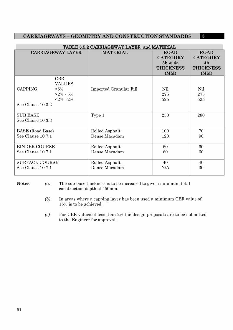
51
CARRIAGEWAYS – GEOMETRY AND CONSTRUCTION STANDARDS 5
TABLE 5.5.2 CARRIAGEWAY LAYER and MATERIAL
CARRIAGEWAY LAYER
MATERIAL
ROAD
CATEGORY
3b & 4a
THICKNESS
(MM)
ROAD
CATEGORY
4b
THICKNESS
(MM)
CAPPING
See Clause 10.3.2
CBR
VALUES
>5%
>2% - 5%
<2% - 2%
Imported Granular Fill
Nil
275
525
Nil
275
525
SUB BASE
See Clause 10.3.3
Type 1 250 280
BASE (Road Base)
See Clause 10.7.1
Rolled Asphalt
Dense Macadam
100
120
70
90
BINDER COURSE
See Clause 10.7.1
Rolled Asphalt
Dense Macadam
60
60
60
60
SURFACE COURSE
See Clause 10.7.1
Rolled Asphalt
Dense Macadam
40
N/A
40
30
Notes: (a) The sub-base thickness is to be increased to give a minimum total
construction depth of 450mm.
(b) In areas where a capping layer has been used a minimum CBR value of
15% is to be achieved.
(c) For CBR values of less than 2% the design proposals are to be submitted
to the Engineer for approval.


53
APPENDIX 5.5 RECOMMENDED HIGHWAY DESIGN STANDARDS FOR RESIDENTIAL DEVELOPMENTS Road
Category
Place
Status
Carriageway
Width
(metres)
Number of
Dwellings
served
Minimum
Constricted
Carriageway
Width (metres)
Minimum
Width of
Footways
(metres)
Design
Speed
(Km/h)
Desirable
Stopping
Distance
(metres)
Minimum
Centre
Line
Radius on
Bends
(metres)
Junction
(metres)
Visibility
Height
(metres)
Maximum
Road
Gradient
Super
Elevation
Desirable Minimum
Spacing
Kerb
Radii
Visibility
Splay
Adjacent Opposite X Y
Secondary
Distributor
(Cat 3b)
Mediu
m
7.3
>500
N/A
2
60
59
127
90
Consult
Engineer
60
Consult
Engineer
12/6
2.4
59
2-0.60
5%
5%
(Max)
Link Road
(Cat 4a)
Low
6.7
300 to 500
N/A
2
48
43
60
60
Consult
Engineer
30
Consult
Engineer
12/6
2.4
43
2-0.60
5%
5%
(Max)
Local access
Road (Cat
4b)
High
5.5
See Note 1
50 to 300
N/A
2
32
25
30
40
Consult
Engineer
20
Consult
Engineer
N/A
2.4
25
2-0.60
5%
Remove
Adverse
Camber
Home Zones
High
See Note 3
<50
3.75
2
16
11
10
40
Consult
Engineer
20
Consult
Engineer
N/A
2.4
11
2-0.60
5%
5%
Remove
Adverse
Camber
Shared
Surface
High
Up to
25
4.8
<25
See Note 2
4.1
N/A
16
11
10
N/A
N/A
N/A
2.4
11
2-0.60
5%
N/A
Note 1;- If a bus is to be routed along the highway a minimum width of 6.7m will be required. Early discussions with bus companies and
the local authority are advised.
Note 2;- A 1.8m wide service corridor is to be provided within the carriageway
Note 3;- Refer to IHIE Home Zone Design Guide
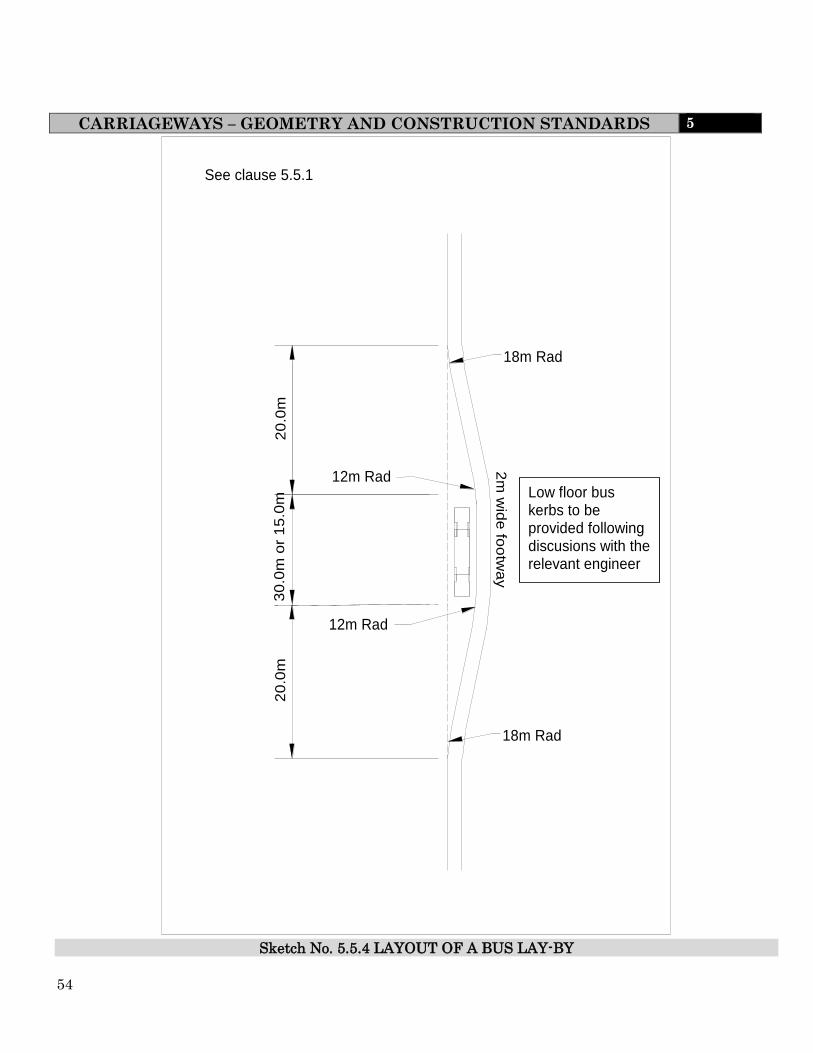
54
CARRIAGEWAYS – GEOMETRY AND CONSTRUCTION STANDARDS 5
See clause 5.5.1
2m
wid
e fo
otw
ay
12m Rad
18m Rad
20
.0m
2
0.0
m
12m Rad
18m Rad
30
.0m
or
15
.0m
Low floor bus kerbs to be provided following discusions with the relevant engineer
Sketch No. 5.5.4 LAYOUT OF A BUS LAY-BY

55
CARRIAGEWAYS – GEOMETRY AND CONSTRUCTION STANDARDS 5
Different turning spaces and useable turning heads
Sketch No. 5.5.5 VEHICLE TURNING AREAS FOR RESIDENTIAL ESTATES

56
SHARED SURFACES 5
5.6 SHARED SURFACES
Concept
The concept of a shared surface is of integrating cars, pedestrians and cyclists. This is in
contrast to the existing principle of segregation and separating different users within the
urban landscape
Pedestrians and Vehicles
In traditional street layouts, footways and carriageways are separated by a kerb. In a
street with a shared surface, this demarcation is absent and pedestrians and vehicles share
the same surface. Shared surface schemes work best in relatively calm traffic
environments.
The following must be adhered to when considering a shared surface
• short lengths, or cul-de-sacs
• the volume of motor traffic is below 100 vehicles per hour (vph) (peak)
• parking is controlled and takes place in designated areas.
Street Furniture
The positioning and quantity and sustainability of planting, street furniture and other
features creating visual clutter must also be taken into consideration.
Disability
Early consultation with the Engineer is recommended when designing shared surfaces as
they can cause problems for some disabled people. This will enable consultation with
Access Officers and disability groups. People with cognitive difficulties may find the
environment difficult to interpret. In addition, the absence of a conventional kerb poses
problems for blind or partially-sighted people, who often rely on this feature to find their
way around. It is therefore important that shared surface schemes include an alternative
means for visually-impaired people to navigate by. Measures should accord with the
Disability Discrimination Act.
It will also be necessary to provide a protected space, with appropriate physical
demarcation, so that those pedestrians who may be unable or unwilling to negotiate
priority with vehicles can use the street safely and comfortably.
Further guidance is available in the best practice on /access too pedestrian and transport
infrastructure ‘Inclusive Mobility’

57
SHARED SURFACES 5
Utility Routes
In shared surface areas the routing of services will require careful consultation between
designers, utility companies and the highway authority. This consultation should take
place at an early stage in the planning and design process. It may be necessary to route
services in the vehicle track in some places, this may not be a significant problem on well-
connected networks. Traffic can be routed around a point closure if it is necessary to
excavate the carriageway for maintenance

58
GEOMETRY & CONSTRUCTION STANDARDS 5
5.7 STATUTORY UNDERTAKERS APPARATUS
The provision of Statutory Undertakers apparatus should generally be in accordance with
Sketch 5.4.2.
The Developer is reminded that all statutory mains must have been taken over by the
relevant authority prior to the development being accepted for adoption.
5.8 VEHICULAR SERVICING OF COMMERCIAL PREMISES
Servicing of commercial premises shall be carried out within curtilage unless other
acceptable provision can be made. Service roads will not be considered for adoption.

59
DESIGN GUIDE FOR INDUSTRIAL DEVELOPMENTS 6
6.0 INDUSTRIAL DEVELOPMENTS
6.1 HIERARCHY OF ROADS
Industrial Distributor Roads (cat 3b) shall be used in large scale industrial
developments.(This will generally apply where the industrial development is likely to
generate more than 175 commercial vehicle trips per day). Access onto such roads should
be restricted to Industrial Access Roads. There should therefore be no direct access to
individual premises and the road should not form a cul-de-sac.
Industrial Access Roads (cat 4a) are those roads onto which direct access is permitted
And they should not attract more than 175 commercial vehicle trips per day. This type
of road should not normally form a cul-de-sac, although this may be permissible in
exceptional circumstances subject to a separate emergency access being provided
which connects to an adopted highway.
6.2 CARRIAGEWAY – GEOMETRY AND CONSTRUCTION STANDARDS
Design – the design of all carriageways in industrial estate developments shall be carried
out in accordance with the requirements of Section 5.2 of this document for category 3a
roads, unless specifically amended by the following overriding clauses. A summary of the
design requirements for industrial estates is detailed in Appendix 6.2.
Junctions – junctions of roads within industrial estates shall be a minimum distance of
90m apart where roads were located on one side of the major road, and 40m apart where
junctions are formed on alternate sides of the major road. The minimum kerb radii at
junctions shall be 12m.
Carriageway Width – the minimum carriageway width for all industrial estate roads
shall be 7.3m, with local widening on bends where necessary using the method described in
TD 9/93 – Highway Link Design.
Visibility – visibility at junctions and accesses should be as clause 5.5.7. However it may
be a requirement on higher category roads for the Y distance to be 70m.
Embankments and Cuttings – should the Developer propose to construct any
embankment or cutting above 2.5m in height or depth, or with side slopes steeper than 1:3,
then reference must be made to Dtp Vol 4 Design Manual for Roads and Bridges. All
designs are to be submitted to the Engineer for approval prior to any work commencing on
site.
Horizontal curves – horizontal curves shall have a minimum centre line radius of 60m.
A reduction in this standard may be acceptable in exceptional circumstances, but only on
Industrial Access Roads with complimentary local widening (see Clause 6.2.3).

60
DESIGN GUIDE FOR INDUSTRIAL DEVELOPMENTS 6
Vehicle turning facilities – turning facilities are to be designed in accordance with
Sketches 6.2.1 and these shall be provided on all cul-de-sacs within industrial estate
developments.
Vehicular access to premises – access to premises shall comply with the geometric
standards detailed in sketch 6.2.1. The access width shall be 10m, although this may be
reduced in circumstances where constraints on the types of vehicle using the site can be
demonstrated, subject to the approval of the Engineer.
Any access shall be built using either the construction standards detailed in Sketch
6.2.2 or by using the construction standards applicable to the main carriageway.
Servicing of commercial premises shall be carried out within the curtilage unless other
acceptable provision can be made to the approval of the Engineer. Service roads will not be
considered for adoption.
Emergency Access – in circumstances where an industrial access road does form a
cul-de-sac, a separate emergency access, which must be adopted, shall be provided and
shall link between adopted highways.
Carriageway Construction – the structural design of carriageways for industrial access
roads shall be in accordance with the construction standards for Category 3a Roads (see
Appendix 6.2).
The structural design of carriageways for Industrial Distributor Roads shall be carried out
in accordance with DfT Vol 7 Design Manual for Roads and Bridges in consultation with
the Engineer.
Channels – Channels shall not be utilised in the construction of industrial estate roads,
unless otherwise agreed with the Engineer.
Site Investigation Report – The Developer shall supply to the Engineer a site
investigation report prepared by a laboratory with appropriate UKAS accreditation
which must include the sulphate content of ground water and soil (reference should be
made to the detailed requirements of Clause 10.1).
6.3 FOOTWAYS AND FOOTPATHS – GEOMETRY AND CONSTRUCTION STANDARDS
The design of all footways and footpaths in industrial estate developments shall be
carried out in accordance with the requirements of Section 5.4, unless specifically amended
by the following overriding clauses.
All Industrial Access Roads shall include a 2m wide footway (measured between restraints)
on both sides of the carriageway. However, for single sided developments, a 2m highway
verge may be provided in lieu of the footway fronting the open area.

61
DESIGN GUIDE FOR INDUSTRIAL DEVELOPMENTS 6
The footways shall may be separated from the carriageway by 2m highway verge or hard
landscaping, which shall be constructed in accordance with the standards detailed in
Section 10.9. In situations where omission of this verge is permitted, footways adjacent to
the carriageway shall be constructed with the depth of binder course increased to 100mm
and the sub-base to 250mm due to the greater vulnerability to vehicle overrun.
6.4 PARKING STANDARDS
Developers should fulfil the parking standards set out in Section 7, which must be outside
the highway proposed for adoption.
6.5 TRAFFIC CALMING
Traffic calming may be considered for industrial estate roads. Such measures may be
required where low vehicle flows and a high standard of carriageway design combine to
encourage high vehicle speeds.
The design of traffic calming measures shall take account of the guidance given in
Section 8 as applied to Category 3a Roads.
6.6 CYCLING FACILITIES
The design of cycling facilities in industrial estate developments shall be carried out in
accordance with the requirements of Section 9. The Developer should consult with the
Engineer at an early stage to determine the nature of cycling facilities to be included as
part of the development.
6.7 STREET LIGHTING
The requirements of Section 11 apply equally to industrial estate developments.
6.8 HIGHWAY DRAINAGE
The requirements of Section 12 apply equally to industrial estate developments.
6.9 HIGHWAY VERGES
The design of highway verges in industrial estate developments shall be carried out in
accordance with the requirements of Section 13 of this document.
6.10 STREET NAME PLATES
The requirements of Section 14 apply equally to industrial estate developments.
.

62
DESIGN GUIDE FOR INDUSTRIAL DEVELOPMENTS 6
6.11 SIGNING AND ROAD MARKING
The requirements of Clause 5.7 apply equally to industrial estate developments
6.12 PUBLIC SAFETY
The requirements of Clause 5.8 apply equally to industrial estate developments.
6.13 STATUTORY UNDERTAKERS APPARATUS
The requirements of Clause 5.9 apply equally to industrial estate developments.
APPENDIX 6.2 HIGHWAY DESIGN STANDARDS FOR INDUSTRIAL DEVELOPMENTS
ROAD TYPE MINIMUM
CARRIAGEWAY
WIDTH
(metres)
MINIMUM
FOOTWAY
WIDTH
(metres)
DESIG
N
SPEED
(km/h)
STOPPING
DISTANCE
(metres)
MINIMUM
CENTRE
LINE
RADIUS
(metres)
MINIMUM
JUNCTION
SPACING
(metres)
Adjacen
t
Opposit
e
Industrial
Estate
Distributor
Road
7.3 2 60 59 60 90 40
Industrial
Estate Access
Road
7.3 2 48 43 60 90 40
MINIMUM
JUNCTION KERB
RADII (metres)
JUNCTION VISIBILITY
SPLAY (metres)
VISIBILITY
HEIGHT
(metres)
MAXIMUM
CARRIAGEWA
Y GRADIENT
MAXIMUM
SUPER
ELEVATION
X-distance Y-distance
12
2.4 59 2.00/0.60
to
2.00/0.60
5% 5%
12
2.4 43 2.00/0.60
to
2.00/0.60
5% 5%²
It may be a requirement on higher category roads for the Y distance to be 70m.
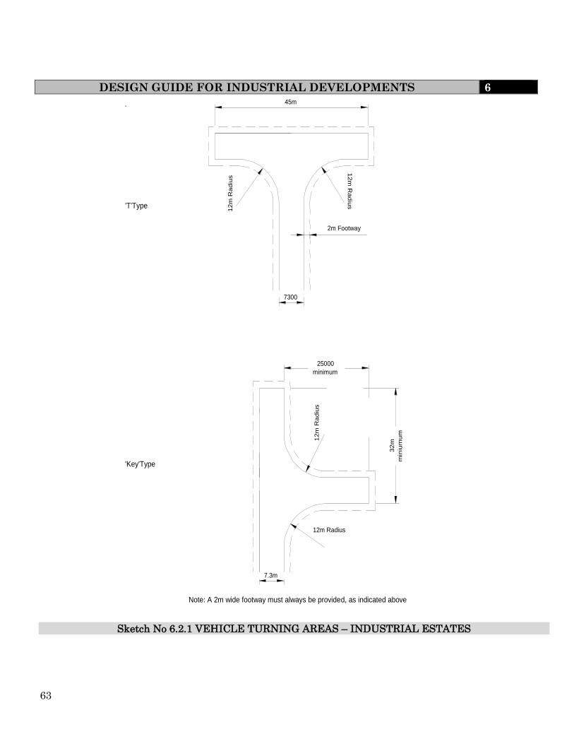
63
DESIGN GUIDE FOR INDUSTRIAL DEVELOPMENTS 6
'T'Type
'Key'Type
Note: A 2m wide footway must always be provided, as indicated above
. 45m
12m
Ra
diu
s 1
2m
Ra
diu
s 2m Footway
7300
25000 minimum
12m
Ra
diu
s
32m
m
iniu
mu
m
12m Radius
7.3m
Sketch No 6.2.1 VEHICLE TURNING AREAS – INDUSTRIAL ESTATES
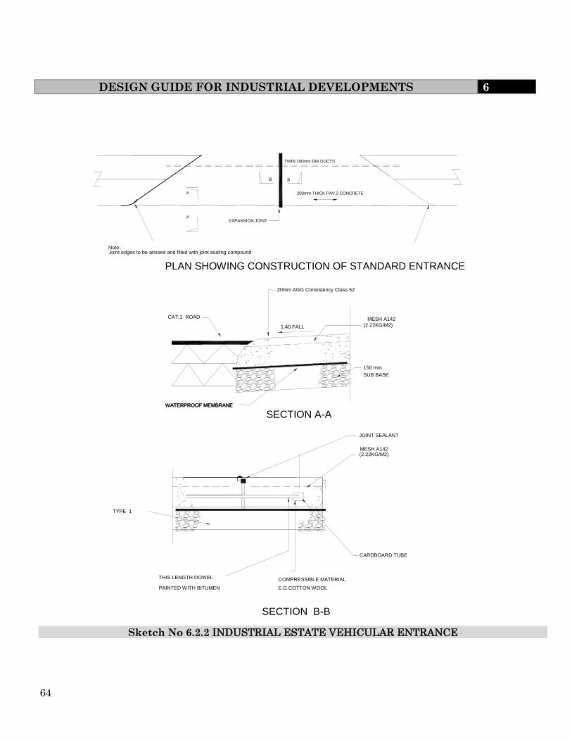
64
DESIGN GUIDE FOR INDUSTRIAL DEVELOPMENTS 6
(2.22KG/M2)
150 mm SUB BASE
CAT.1 ROAD
WATERPROOF MEMBRANE
1:40 FALL
WATERPROOF MEMBRANE
20mm AGG Consistency Class 52
A
A
B B
JOINT SEALANT
MESH A142
CARDBOARD TUBE
COMPRESSIBLE MATERIAL E.G.COTTON WOOL
THIS LENGTH DOWEL PAINTED WITH BITUMEN
TYPE 1
SECTION A-A
SECTION B-B
MESH A142
(2.22KG/M2)
EXPANSION JOINT
TWIN 100mm DIA DUCTS
200mm THICK PAV.2 CONCRETE
Note: Joint edges to be arissed and filled with joint sealing compound
PLAN SHOWING CONSTRUCTION OF STANDARD ENTRANCE
Sketch No 6.2.2 INDUSTRIAL ESTATE VEHICULAR ENTRANCE

65
DESIGN GUIDE FOR PARKING STANDARDS 7
For Stockton Borough Council please go to http://www.stockton.gov.uk/resources/transportstreets/48506/parkprov/parkingprov.pdf
It may also be necessary to contact the appropriate Authority to ascertain if there is
any relevant Supplementary Planning Guidance.
7.1 INTRODUCTION
The Need to Manage Demand
Every development results in a demand for parking or loading space. This demand must,
however, be viewed in the context of the Government’s Sustainable Development Strategy.
The approach to this strategy is outlined in regard to parking in Department of
Communities and Local Government’s National Planning Policy Framework
The aim of this policy is to;
“actively manage patterns of growth to make the fullest possible use of public transport,
walking, cycling;”
The aims are intended to assist in sustaining existing centres.
The availability of parking has a major influence on the choice of means of transport.
The National Planning Policy Framework (NPPF) suggests that the transport system
needs to be balanced in favour of sustainable transport modes, giving people a real choice
about how they travel. In considering parking, therefore, the effects of the level of
provision must take into account the impact on vehicle trips and the need to address the
encouragement of alternative modes of travel, in particular public transport, cycling and
walking.
Local authorities should aim to influence the need to travel by, amongst other means,
limiting parking provision for developments where there are effective alternatives. In
principle and in practice this means that standards are reduced below the levels considered
appropriate when full parking, as a minimum provision, was expected.
In general, therefore the following principles apply,
(i) Reduced requirements for parking for locations which have
good access to other means of travel than the private car.
(ii) Flexibility in regard to off-street residential parking provision
particularly in association with high-density development in areas with good access by
non-car modes

66
DESIGN GUIDE FOR PARKING STANDARDS 7
The NPPF states that authorities recognise town centres as the heart of their communities
and pursue policies to support their viability and vitality.
Car parking is only one element in the strategy for securing sustainable
development. An integrated approach is necessary and as a consequence ways of
reducing travel, influencing traffic growth and improving environmental impacts
of transport are evolving and will continue to do so. These will be presented in
local policy and strategy documents and hence early consultation with the
Engineer is recommended.
In all areas please be advised that car parking levels will generally be the maximum
provision.
7.2 POLICY CONSIDERATIONS
National Policies
The NPPF, along with a number of other strategic policy documents refer to parking
standards. These include:
Planning Policy Statement PPS 6 ‘Town Centres’
Regional Spatial Strategy
Manual for Streets 2007
These documents are considered in more detail below.
positively discriminates in favour of sustainable development, and therefore the promotion
of alternative modes of transport to the private car and parking provision levels.
Paragraph 39 of the NPPF states that when setting local parking standards for
developments the following should be taken into account
The accessibility of the development
The type, mix and use of development
The availability of opportunities for public transport
Local car ownership levels
An overall need to reduce the use of high emission vehicles
The Government does recognise that that different policies and measures will be required
in different communities and opportunities to maximise sustainable transport solutions
will vary from urban to rural. It must be noted, that the bus will remain the predominant
public transport mode within the Tees Valley. Bus stop locations will be reviewed to ensure
they are in the optimum location and standard kerb heights to accommodate low floor
buses
Local Policies
There may be variations of these Parking Standards within each borough for specially
defined Regeneration areas. These variations may differ greatly from the standards set out
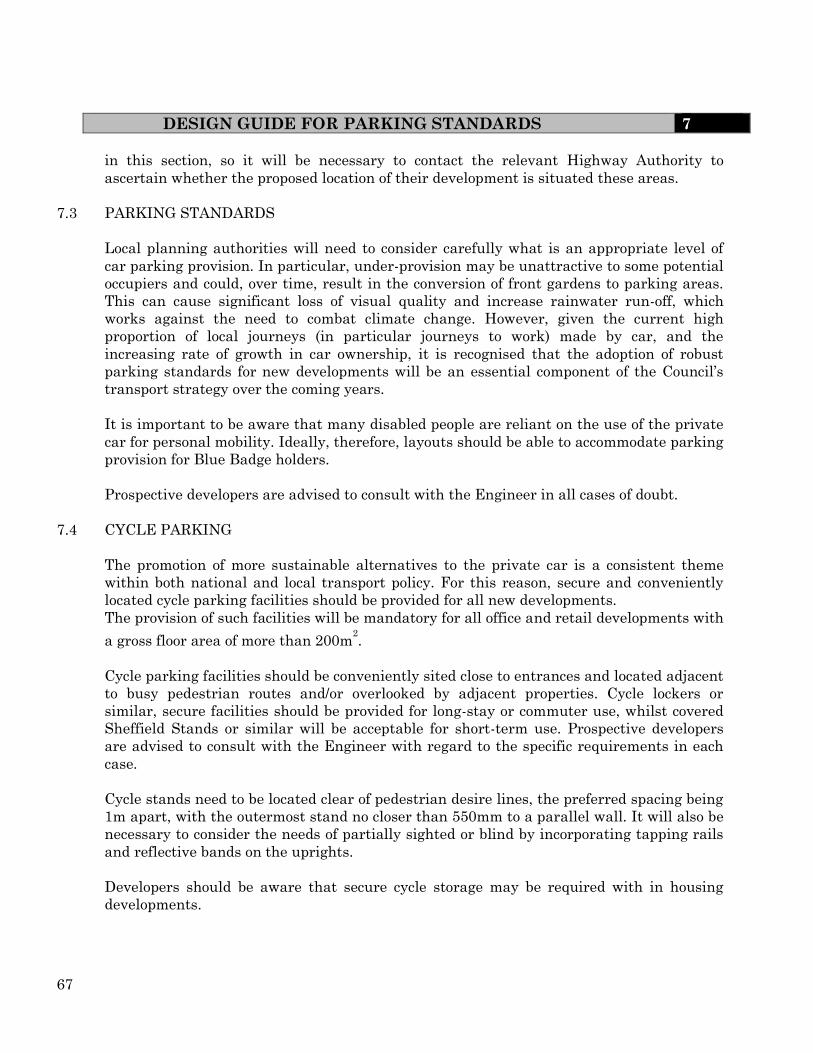
67
DESIGN GUIDE FOR PARKING STANDARDS 7
in this section, so it will be necessary to contact the relevant Highway Authority to
ascertain whether the proposed location of their development is situated these areas.
7.3 PARKING STANDARDS
Local planning authorities will need to consider carefully what is an appropriate level of
car parking provision. In particular, under-provision may be unattractive to some potential
occupiers and could, over time, result in the conversion of front gardens to parking areas.
This can cause significant loss of visual quality and increase rainwater run-off, which
works against the need to combat climate change. However, given the current high
proportion of local journeys (in particular journeys to work) made by car, and the
increasing rate of growth in car ownership, it is recognised that the adoption of robust
parking standards for new developments will be an essential component of the Council’s
transport strategy over the coming years.
It is important to be aware that many disabled people are reliant on the use of the private
car for personal mobility. Ideally, therefore, layouts should be able to accommodate parking
provision for Blue Badge holders.
Prospective developers are advised to consult with the Engineer in all cases of doubt.
7.4 CYCLE PARKING
The promotion of more sustainable alternatives to the private car is a consistent theme
within both national and local transport policy. For this reason, secure and conveniently
located cycle parking facilities should be provided for all new developments.
The provision of such facilities will be mandatory for all office and retail developments with
a gross floor area of more than 200m2.
Cycle parking facilities should be conveniently sited close to entrances and located adjacent
to busy pedestrian routes and/or overlooked by adjacent properties. Cycle lockers or
similar, secure facilities should be provided for long-stay or commuter use, whilst covered
Sheffield Stands or similar will be acceptable for short-term use. Prospective developers
are advised to consult with the Engineer with regard to the specific requirements in each
case.
Cycle stands need to be located clear of pedestrian desire lines, the preferred spacing being
1m apart, with the outermost stand no closer than 550mm to a parallel wall. It will also be
necessary to consider the needs of partially sighted or blind by incorporating tapping rails
and reflective bands on the uprights.
Developers should be aware that secure cycle storage may be required with in housing
developments.

68
DESIGN GUIDE FOR PARKING STANDARDS 7
Cycle parking - Good practice
Visible Parking facilities should be easy to find.
Accessible Parking should be as close as possible to the destination, small
clusters of stands in a town centre are preferable to one large parking
area. Under-used stands may be relocated to areas of higher demand if
necessary.
Safe and
Secure
The bicycle is usually secured with the owner’s lock unless other
security arrangements make this unnecessary. Cycle parking should
not be sited in areas where this would cause personal security
concerns. Long term parking for regular users in residential,
educational and workplace areas should ideally be placed within a
secure access area.
Covered The level of protection from the weather should be appropriate for the
length of stay. Long-stay parking places should be covered.
Easy to use Parking facilities should be easy to use, accept all types of bicycle, and
enable the frame to be secured. Public locking mechanisms such as
coin-operated locks should be easy to understand and operate. Bikes
should not normally need to be lifted into parking stands. Cycle pods
may be used but do involve some lifting,
Fit for
purpose
Stands which only grip the front wheel should not be used due to the
damage which can result in their use. Parallel stands should be at
least 1.0m apart. Cycle parking should not cause a trip hazard or an
obstruction for disabled persons. Abandoned bicycles should be
periodically removed.
Well
managed
and well
maintained
Charges for lockers or staffed parking (if any) should not be excessive
to encourage use. The payment/registration process should be as
simple as possible. Automated carousels or smart card operation
should not create delays at peak periods
Attractive The design of cycle parking facilities should be appropriate to the
surrounding area to match other street furniture.
Coherent Cycle parking should sit within the context of a cycle route network
connecting the main origins and destinations.
Linked to
other needs
of cyclists.
At public transport interchanges and cycle centres, opportunities to
combine cycle parking, hire, repair and tourism may be developed.
7.5 MOTOR CYCLE PARKING
In terms of convenience, flexibility and security considerations, motorcycles are often more
like bicycles than cars. Consequently, the behaviour and requirements of motorcyclists
often follow the cycle parking model with motorcyclists looking for similar features.
Motorcycle riders will look for obvious parking opportunities close to their destination,
choosing convenient places, ideally where they can secure their machine to something

69
DESIGN GUIDE FOR PARKING STANDARDS 7
immovable, or where they can see or stay close to their machine or at the very least where
it is likely to receive maximum casual observation so the risk of theft can be minimised.
Covered off-street parking is desirable clearly signed, convenient and secure parking
reduces the attraction of informal parking. On the other hand inadequate provision will
lead to exploitation of inappropriate opportunities, which may result in motorcycles
causing a genuine obstruction or hazard to others.
7.5.1 Design
Motorcycle bays are not required to be formally marked for individual motorcycles but
should be in multiples of 1.4m wide by 2.7m in length. This will allow sufficient space for
the rider to mount/dismount and for manoeuvring. They should also be set at right angles
to the kerb.
Motorcycle parking should be located;
Where it has good all round visibility, and overlooked by adjacent properties and
passers-by. It should not have high walls/fences and no dense shrubs.
As close as possible to the main entrance of buildings, but not so that it hinders or is
dangerous to the public.
In areas with good lighting
The preferred design for motorcycle parking will include;
A ground anchor or rail to which the motorcycle can be securely locked. The design
of the anchor point(s) and layout of the site should not present additional hazards to
or from, other road users and vehicles. Pedestrians, especially those with visual or
mobility impairment can be especially vulnerable – a rail set at shin height may be
acceptable when mounted on a wall at the rear of an off-road parking bay, but not in
the street where extra measures will need to be taken to provide protection.
Good lighting and clear signage is essential
Some form of weather protection. This should include a roof and protection on 3
sides
The area should be level or on easy gradients, which will ensure that the motorcycles will
not topple over. The areas must have a firm surface capable of supporting the weight of a
motorcycle through its stand.
Further advice can be obtained in the current Traffic Advisory Leaflet ‘Motorcycle Parking’

70
DESIGN GUIDE FOR PARKING STANDARDS 7
7.6 TRAVEL PLANNING
The NPPF promotes Travel Plans as a means of reducing car usage and increasing use of
public transport, walking and cycling. The Council will require the submission of Travel
Plans on all developments where indicative thresholds in Guidance on Transport
Assessments (DfT - March 2007) are exceeded.
Travel Plans should seek to provide a range of measures and incentives to facilitate the use
of alternative modes of transport. These measures should be based on a thorough
understanding of the actual or projected travel movements of employees, residents and
students (for educational establishments). Clear targets should be set to allow the Travel
Plan to be monitored and reviewed. Mechanisms for penalty measures may be sought in
Travel Plans where it is considered that this is appropriate. These will be triggered in the
event that agreed targets contained in the Plan are not met.
A checklist has been developed to assess the content of submitted Travel Plans. This can
be obtained from the relevant Engineer. Travel Plans that do not provide reasonable
consideration of the issues in the checklist will not be considered fit for purpose.
Further information on employer, school and residential Travel Plans is provided at
www.teesvalleytravelplans.co.uk and in good practice guidance published by the
Department for Transport, available from www.dft.gov.uk.
7.7 COMMUTED SUMS
Section 106 of the Town and Country Planning Act 1990 allows the Council to secure funds
(known as commuted lump sums) through the planning process to provide measures that
assist with parking, road safety and congestion management.
Where provision in line with the parking standards cannot be made on or near a particular
development site, the Engineer will consider if such funding could be used to introduce
initiatives designed to encourage the use of other, more sustainable forms of transport.
Such initiatives could typically take the form of new bus services, support for existing
services to improve frequency, or infrastructure e.g. new shelters and real time displays,
new cycle facilities or measures designed to enhance pedestrian safety.
Such sums could also be used to fund the introduction of car clubs and /or car share spaces
and any associated infrastructure and administrative costs. The appropriateness and
relevance of commuted sum payments will be considered in the context of the
circumstances specific to each development and as local policies and strategies evolve.

71
DESIGN GUIDE FOR PARKING STANDARDS 7
7.8 PEOPLE WITH DISABILITIES
In accordance with national guidance, consideration should always be given to the needs of
disabled people. The location of parking provision is particularly important in this context.
In particular, allocated spaces should be:
Located be as close as possible to the destination;
Connected to the destination without steps (ramps or lifts may be necessary,
depending on local circumstances); and
Sufficiently large to allow unobstructed wheelchair access.
The location of disabled parking spaces within a new development should be considered at
an early stage to achieve a balanced distribution throughout the site.
The recommended number of disabled spaces will vary in accordance with the type and
capacity of car parks, as illustrated in Table 7.3
(i) For car parks associated with employment premises and provided for employees
and visitors
Up to 10 spaces 1 space
Between 10 and 200 spaces; 5% of capacity, subject to a minimum of 2 spaces, to be
reserved.
Over 200 spaces: 2% plus 6 spaces.
Spaces for disabled employees should be additional to those recommended above;
reservations could be ensured, for example, by marking a space with a registration
number.
For car parks associated with shopping areas, leisure or recreational facilities and places
open to the general public:
Up to 10 spaces 1 space
Between 10 and 200 spaces: 6% of capacity subject to a minimum of 3 spaces,
to be reserved;
Over 200 spaces: 4% plus 4 spaces.

72
DESIGN GUIDE FOR PARKING STANDARDS 7
Parking for disabled people should be additional to the maximum parking
standards. Development proposals should provide adequate parking for disabled
motorists, in terms of numbers and design. The signage and markings for
disabled bays on streets should comply with TSRGD and be supported by a TRO.
Developers are advised that in all car parks, the use of spaces reserved for disabled people
should be monitored regularly to confirm that the recommended level of provision is
appropriate – too few spaces will cause problems for disabled drivers and passengers, while
too many spaces may encourage abuse by other drivers. The responsibility for monitoring
the use of reserved parking spaces within a private development will rest with the end
user(s) of that development, usually as part of the adopted Travel Plan for the site.
BS 8300:2001 (‘Design of Buildings and their Approaches to Meet the Needs of Disabled
People’) explains how to design the built environment to make it fully accessible, and to
overcome restrictions that prevent anyone from making full use of premises and their
surroundings. The code of practice, which covers a wide range of impairments and
activities, provides specific guidance with regard to:
The provision and design of parking bays designated for disabled people in different
building types;
(ii) Ticket dispensing machines;
(iii) Vehicular control barriers; and
(iv) Multi-storey car parks.
Parking bays for disabled people should be designed so that drivers and passengers, either
of whom may be disabled, can get in and out of the car easily and safely. Bays should be
longer and wider than normal. They ensure easy access from the side and the rear for those
with wheelchairs, and protect disabled people from moving traffic when they cannot get in
or out of their car on the footway side of a bay on the highway.
Other Design Considerations
Steps, Ramps, Bollards and Lifts - Pedestrian routes to and from car parks with bays
for disabled people should be free from steps, bollards and steep slopes which many
disabled people find difficult to negotiate. See sketch 7.1.
7.9 DIFFERENTIAL STANDARDS IN CENTRAL AND NON-CENTRAL AREAS
There is a clear distinction in the levels of parking provision permitted for central area and
non-central area development. Within central areas (i.e. town centres), developers will
normally be allowed to provide for operational parking only. Outside these areas, this
requirement will be relaxed to allow a certain level of non-operational parking* to be
provided. *for definition see Clause 7.10
This policy is designed to achieve a number of objectives. It will minimise the inefficient
use of high value land in town centres and will also allow the Council to retain control over
the extent and use of off-street parking provision. This is an important part of the Council’s
overall transport and land

73
DESIGN GUIDE FOR PARKING STANDARDS 7
use strategy. In addition, it will avoid the potential loss of urban form and character in
town centres and local neighbourhoods.
Meeting the parking needs of non-operational traffic associated with individual
development proposals within town centres will result in the haphazard distribution of
private car parks, not necessarily related to the local road network. The existence of
unrelated and unregulated car parks, to which access must be maintained, acts as a
serious constraint to the Council’s ability to discharge its ongoing Network Management
Duty under the Traffic Management Act 2004.
Concentrating the provision made for non-operational parking in town centres in the form
of strategically located car parks, available for use by the general public and with good
access arrangements, both encourages the more efficient operation of those centres and
facilitates the formulation and implementation of effective car parking and traffic
management strategies.
The control of town centre parking also allows the Council, as Highway
Authority, to exert more influence over strategic issues such as the modal ‘split’
between private and public transport.
In short, the adoption of an effective parking management policy in central areas is key to
ensuring the continued vitality of the Borough’s town centres. Only the Council, as both
Highway and Planning Authority, can regulate such a policy effectively
The town centres within a Borough are defined in the adopted Local Development
Framework. Prospective developers are asked to contact the appropriate Council to clarify
the extent of the defined area in case of doubt.
7.10 OPERATIONAL AND NON-OPERATIONAL PARKING
Operational Parking
Operational parking is defined as the space required for cars and service vehicles
necessarily involved in the operation of the business of particular buildings. It comprises
space for vehicles servicing premises, primarily commercial vehicles delivering or collecting
goods. Also staff who need to use a car to carry out their duties on a daily basis. In
addition to the space required for loading and unloading, operational parking also includes
space for picking up and setting down passengers. It does not normally include
customer/client parking unless this is necessary as part of the business being carried out,
for example vehicle servicing and tyre/exhaust replacement.
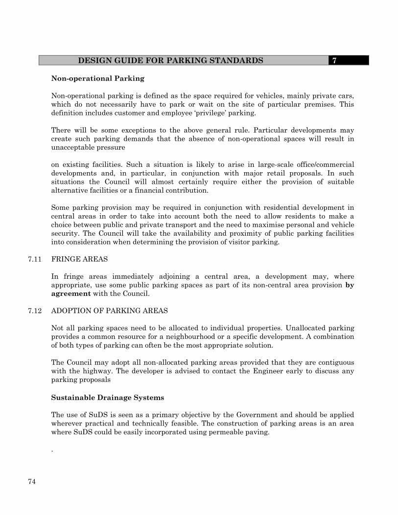
74
DESIGN GUIDE FOR PARKING STANDARDS 7
Non-operational Parking
Non-operational parking is defined as the space required for vehicles, mainly private cars,
which do not necessarily have to park or wait on the site of particular premises. This
definition includes customer and employee ‘privilege’ parking.
There will be some exceptions to the above general rule. Particular developments may
create such parking demands that the absence of non-operational spaces will result in
unacceptable pressure
on existing facilities. Such a situation is likely to arise in large-scale office/commercial
developments and, in particular, in conjunction with major retail proposals. In such
situations the Council will almost certainly require either the provision of suitable
alternative facilities or a financial contribution.
Some parking provision may be required in conjunction with residential development in
central areas in order to take into account both the need to allow residents to make a
choice between public and private transport and the need to maximise personal and vehicle
security. The Council will take the availability and proximity of public parking facilities
into consideration when determining the provision of visitor parking.
7.11 FRINGE AREAS
In fringe areas immediately adjoining a central area, a development may, where
appropriate, use some public parking spaces as part of its non-central area provision by
agreement with the Council.
7.12 ADOPTION OF PARKING AREAS
Not all parking spaces need to be allocated to individual properties. Unallocated parking
provides a common resource for a neighbourhood or a specific development. A combination
of both types of parking can often be the most appropriate solution.
The Council may adopt all non-allocated parking areas provided that they are contiguous
with the highway. The developer is advised to contact the Engineer early to discuss any
parking proposals
Sustainable Drainage Systems
The use of SuDS is seen as a primary objective by the Government and should be applied
wherever practical and technically feasible. The construction of parking areas is an area
where SuDS could be easily incorporated using permeable paving.
.

75
DESIGN GUIDE FOR PARKING STANDARDS 7
7.13 SAFER PARKING AWARD (PARK MARK)
It is a recommendation that developers ensure that their facility meets the requirements of
the ‘Park Mark’ award. This scheme is an initiative of the Associations of Chief Police
Officers aimed at reducing crime and the fear of crime in parking facilities. To assist in this
a set of best practice guidelines have been published by the Safer Parking Scheme
7.14 TOWN AND COUNTRY PLANNING (USE CLASSES) (AMENDMENT) (ENGLAND)
ORDER 2005
It is clear that some developments within the same Use Class Order will have widely
differing parking requirements (e.g. category A3 Public Houses/Hot Food Take-Aways and
B1 Industrial Use).
For this reason the Council, as Planning Authority will, under normal circumstances,
insist that the future use of a particular site shall be restricted to that specified within the
planning application, provided that the appropriate level of parking provision can be
achieved. A Section 106 Agreement, made under the Town & Country Planning Act 1990,
may be required in this respect. The Use Classes Order and the permitted changes of use
within it are illustrated in Table 7.1.

76
DESIGN GUIDE FOR PARKING STANDARDS 7
Table 7.1 Use Classes Use/Description of Development Permitted Change
A1 Shops Retail sale of goods to the public – Shops, Post
Offices, Travel Agencies & Ticket Agencies,
Hairdressers, Funeral Director & Undertakers,
Domestic Hire Shops, Dry Cleaners.
• Sandwich Bars – Sandwiches or other cold food
purchased and consumed off the premises, Internet
Cafes
None
A2 Financial and
Professional
Services
• Financial Services – Banks, Building Societies
and Bureau de Change.
• Professional Services (other than Health or
Medical Services) – Estate Agents and
Employment Agencies. • Other Services - Betting Shops. Principally where
services are provided to visiting members of the
public
Permitted change to
A1 where a ground
floor display window
exists
A3 Food and
Drink
• Restaurants and Cafes – Use for the sale of food for
consumption on the premises. Excludes Internet
Cafes (now A1)
Permitted change to
A1 or A2
A4 Drinking
Establishments
• Use as a Public House, Wine-Bar or other Drinking
Establishment
Permitted change to
A1, A2 or A3
A5 Hot Food
Takeaways
• Use for the sale of hot food for consumption off the
premises Permitted change
to A1, A2 or A3 B1 Business • Offices other than in a use within Class A2.
•Research and Development – Studios,
Laboratories. • Light industry.
Permitted change to
B8 where no more
than 235m
B2 General
Industry • General Industry (other than Classified as in
B1) The former ‘Special Industrial’ Use Classes, B3-B7,
are all now encompassed in the B2 Use Class
Permitted change
to B1 or B8 where
limited to 235m
B8 Storage or
Distribution
• Storage or Distribution Centres – Wholesale
Warehouses, Distribution Centres & Repositories
Permitted change to
B1 where no more
than 235m²
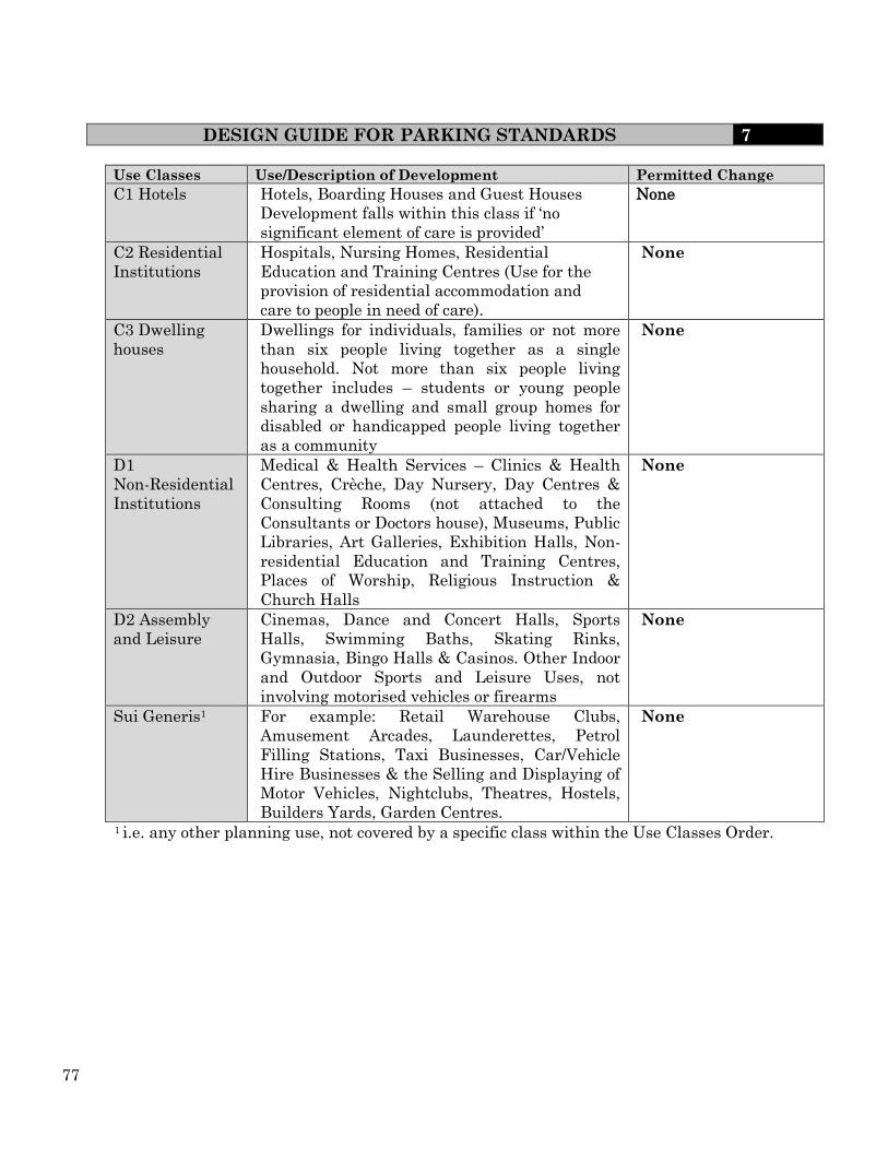
77
DESIGN GUIDE FOR PARKING STANDARDS 7 Use Classes Use/Description of Development Permitted Change
C1 Hotels
Hotels, Boarding Houses and Guest Houses
Development falls within this class if ‘no
significant element of care is provided’
None
C2 Residential
Institutions
Hospitals, Nursing Homes, Residential
Education and Training Centres (Use for the
provision of residential accommodation and
care to people in need of care).
None
C3 Dwelling
houses
Dwellings for individuals, families or not more
than six people living together as a single
household. Not more than six people living
together includes – students or young people
sharing a dwelling and small group homes for
disabled or handicapped people living together
as a community
None
D1
Non-Residential
Institutions
Medical & Health Services – Clinics & Health
Centres, Crèche, Day Nursery, Day Centres &
Consulting Rooms (not attached to the
Consultants or Doctors house), Museums, Public
Libraries, Art Galleries, Exhibition Halls, Non-
residential Education and Training Centres,
Places of Worship, Religious Instruction &
Church Halls
None
D2 Assembly
and Leisure
Cinemas, Dance and Concert Halls, Sports
Halls, Swimming Baths, Skating Rinks,
Gymnasia, Bingo Halls & Casinos. Other Indoor
and Outdoor Sports and Leisure Uses, not
involving motorised vehicles or firearms
None
Sui Generis1 For example: Retail Warehouse Clubs,
Amusement Arcades, Launderettes, Petrol
Filling Stations, Taxi Businesses, Car/Vehicle
Hire Businesses & the Selling and Displaying of
Motor Vehicles, Nightclubs, Theatres, Hostels,
Builders Yards, Garden Centres.
None
1 i.e. any other planning use, not covered by a specific class within the Use Classes Order.

78
DESIGN GUIDE FOR PARKING STANDARDS 7
4.8m 4.8m 6.0m 6.0m
5.4m One Way
2.4m
2.4m
3.0m One Way
4.5m
4.5m
4.9m
3.4m
2.4m
2.75m
End On Parking
3.6m One Way
5.1m
5.1m
4.2m One Way
5.4m
5.4m
6.0m Two Way
4.8m
4.8m
Side Parking 0°
30°
45°
60°
90°
Alternative Parking Layouts N.B. These arrangements are not normally acceptable adjacent to highways
3.0m One Way
Sketch No 7.1 PARKING DIMENSIONAL REQUIREMENTS
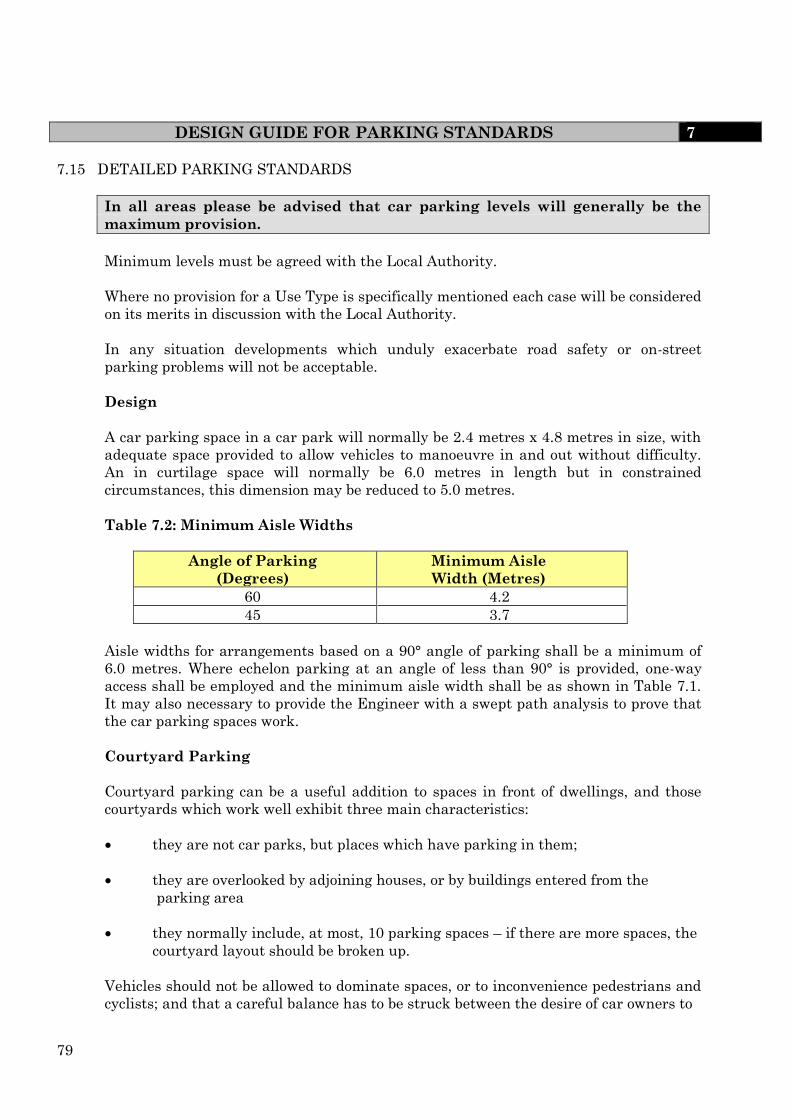
79
DESIGN GUIDE FOR PARKING STANDARDS 7
7.15 DETAILED PARKING STANDARDS
In all areas please be advised that car parking levels will generally be the
maximum provision.
Minimum levels must be agreed with the Local Authority.
Where no provision for a Use Type is specifically mentioned each case will be considered
on its merits in discussion with the Local Authority.
In any situation developments which unduly exacerbate road safety or on-street
parking problems will not be acceptable.
Design
A car parking space in a car park will normally be 2.4 metres x 4.8 metres in size, with
adequate space provided to allow vehicles to manoeuvre in and out without difficulty.
An in curtilage space will normally be 6.0 metres in length but in constrained
circumstances, this dimension may be reduced to 5.0 metres.
Table 7.2: Minimum Aisle Widths
Angle of Parking
(Degrees)
Minimum Aisle
Width (Metres)
60 4.2
45 3.7
Aisle widths for arrangements based on a 90° angle of parking shall be a minimum of
6.0 metres. Where echelon parking at an angle of less than 90° is provided, one-way
access shall be employed and the minimum aisle width shall be as shown in Table 7.1.
It may also necessary to provide the Engineer with a swept path analysis to prove that
the car parking spaces work.
Courtyard Parking
Courtyard parking can be a useful addition to spaces in front of dwellings, and those
courtyards which work well exhibit three main characteristics:
they are not car parks, but places which have parking in them;
they are overlooked by adjoining houses, or by buildings entered from the
parking area
they normally include, at most, 10 parking spaces – if there are more spaces, the
courtyard layout should be broken up.
Vehicles should not be allowed to dominate spaces, or to inconvenience pedestrians and
cyclists; and that a careful balance has to be struck between the desire of car owners to

80
DESIGN GUIDE FOR PARKING STANDARDS 7
park as near to their dwellings as possible and the need to maintain the character of the
overall setting.
Garage Sizes
The minimum garage size is to be 6m x 3m, any smaller and it will not count towards
the parking allocation (car width 2m and 0.5m to open door and 0.3 clear space; car
length 4.5m with 0.35 clear space)
Sketch 7.1 illustrates some indicative parking arrangements.
These standards are intended to offer guidance on the appropriate level of
parking provision to be made for different types of land use. It should be stressed
that, for non-residential developments, THE STANDARDS SET OUT THE
MAXIMUM LEVEL OF PROVISION THAT WILL NORMALLY BE
PERMITTED.
Land Use Class Parking Provision
Disabled Parking Provision
Secure Cycle Parking Notes
Residential Care Homes for the Elderly
C2 Sufficient operational parking and area. For maneuvering within the site.1 space per 3 members of staff on duty at one time. 1 space per 8 residents (visitor provision). 1 space for professional visitor.
10% 1 space per 4 members of staff
Specialist care/nursing
Residential Institutions
C2 1 space per permanent member of staff. 1 space per 5 residents/ visitors
10% 1 space per 4 employees
Student Accommodation
Sufficient operational parking and area for manoeuvring within the site. 1 space per cluster (up to 6 beds). Provision for the parking of 6 cycles per 30 residents

81
DESIGN GUIDE FOR PARKING STANDARDS 7 Table 7.3
Land Use Class Parking Provision
Disabled Parking Provision
Secure Cycle Parking Notes
House 1/2
Bed C3 2 N/A N/A
Garages will be
counted as a
space if they are
a minimum of
6m x 3m
internal size
House 3 Bed C3 2 N/A N/A
Garages will be
counted as a
space if they are
a minimum of
6m x 3m
internal size
House 4 Bed C3 3 N/A N/A
Garages will be
counted as a
space if they are
a minimum 0f
6m x 3m
internal size
House 5
Bed and
Over
C3 3 N/A N/A
Garages will be
counted as a
space if they are
a minimum of
6m x 3m
internal size
Flatted
Development C3 1.5 10%
1 space
per 4
flats up
to 100
flats
Developments
over 100 flats
discussions
must take place
with the
Engineer,
Local
Authority
Housing/
Registered
Social
Landlords
C3 1 Flats
10% N/A
Sheltered
Housing
Category 1
C3
2 Spaces per resident
warden, 1 space per 5
residents
10% N/A
Communal
facilities with
independent
living – 1
bedroom only
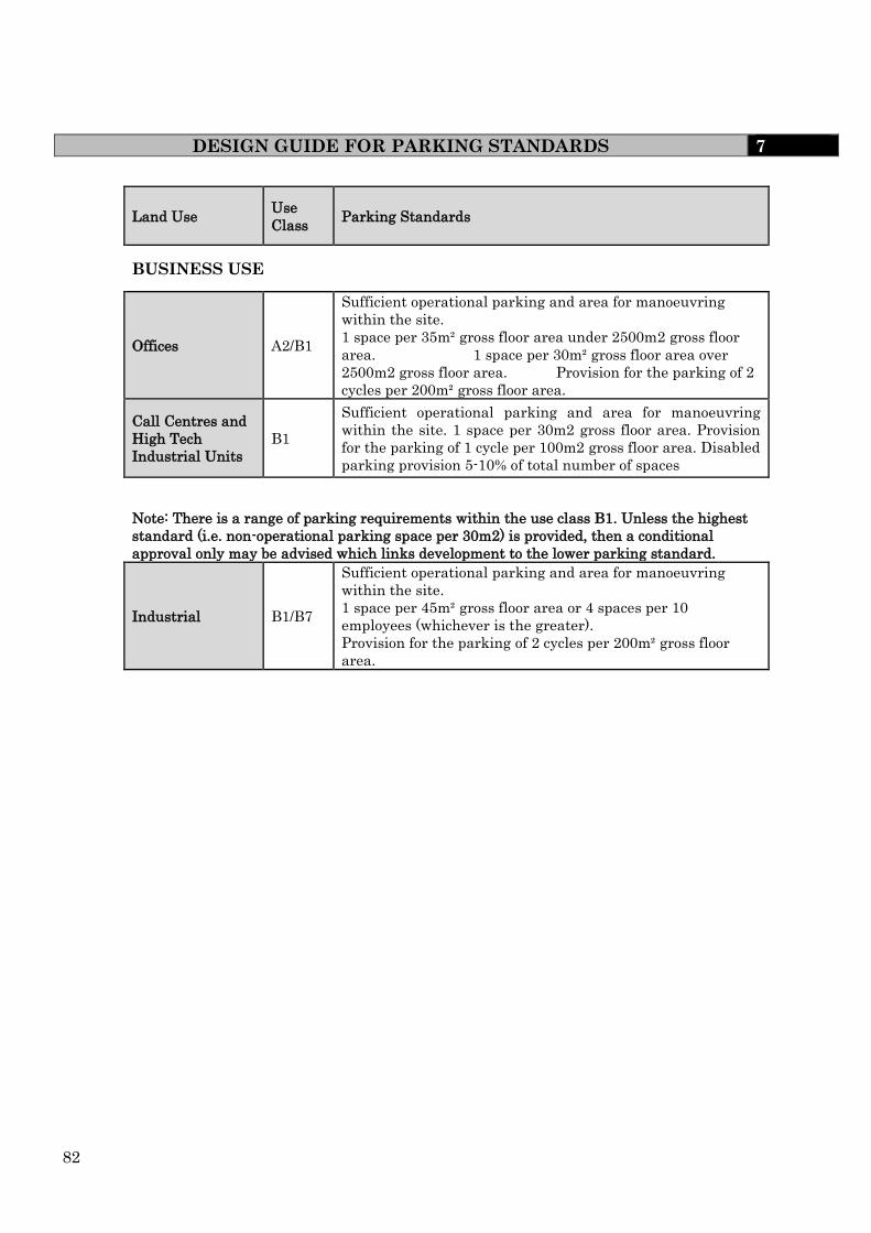
82
DESIGN GUIDE FOR PARKING STANDARDS 7
Land Use Use
Class Parking Standards
BUSINESS USE
Offices A2/B1
Sufficient operational parking and area for manoeuvring
within the site.
1 space per 35m² gross floor area under 2500m2 gross floor
area. 1 space per 30m² gross floor area over
2500m2 gross floor area. Provision for the parking of 2
cycles per 200m² gross floor area.
Call Centres and
High Tech
Industrial Units
B1
Sufficient operational parking and area for manoeuvring
within the site. 1 space per 30m2 gross floor area. Provision
for the parking of 1 cycle per 100m2 gross floor area. Disabled
parking provision 5-10% of total number of spaces
Note: There is a range of parking requirements within the use class B1. Unless the highest
standard (i.e. non-operational parking space per 30m2) is provided, then a conditional
approval only may be advised which links development to the lower parking standard.
Industrial B1/B7
Sufficient operational parking and area for manoeuvring
within the site.
1 space per 45m² gross floor area or 4 spaces per 10
employees (whichever is the greater).
Provision for the parking of 2 cycles per 200m² gross floor
area.

83
DESIGN GUIDE FOR PARKING STANDARDS 7
Retail
Land Use Use
Class Parking Standards
Supermarkets/
Warehouses over
1000m2 gross
floor space
A1
Sufficient operational parking and area for manoeuvring
within the site.
Food retail – 1 space per 14m2 gross floor area.
Non food retail – 1 space per 20m2 gross floor area.
Precise parking levels for large developments will be
established by a Transport Assessment agreed by both the
developer and the Council.
Provision for the parking of 1 cycle per 100m2 gross floor
area.
The Council may require a condition or a section 106
agreement limiting the retail use to suit available parking
Retail under
1000m2 gross
floor space
A1
Sufficient operational parking and area for manoeuvring
within the site.
1 space per 30 m² gross floor area.
Provision for the parking of 2 cycles per 100m² gross floor
area or per unit, whichever is the greater.
Car Boot Sales Sui
generis
Sufficient operational parking and area for manoeuvring
within the site.
1 space per stall/pitch for sellers. 3 spaces per stall/pitch for
customers. Provisions for the parking of 4 cycles per 500m²
GDA. Early discussions with the Engineer will be required
Garden Centres A1
Sufficient operational parking and area for manoeuvring
within the site.
1 space per 30m² GDA (Gross Display Area). Provision for the
parking of 2 cycles per 200m² GDA.
Warehouses
Warehouses B8
Sufficient operational parking and area for manoeuvring
within the site.
1 space per 100m² gross floor area or 1 space per 2 employees
(whichever is the greater).
Provision for the parking of 2 cycles per 400m² gross floor
area.

84
Motor Car
Showrooms Sui
generis
Sufficient operational parking and area for manoeuvring
within the site.
1 space per 200m² internal/external display area for
customers. 0.5 space per member of staff.
Provision for the parking of 2 cycles per 500m² gross floor
area or per outlet.
Whichever is the greater. 5% of total number of parking
spaces designated for use by disabled people.
Garages B1
Sufficient operational parking and area for manoeuvring
within the site.
3 spaces per service bay plus 1 space per employee.
Provision for the parking of 2 cycles per 500m² gross floor
area or per unit if smaller.
Tyre and Exhaust
Centres B1
Sufficient operational parking and area for manoeuvring
within the site. 3 space per bay.
1 space per member of staff.
1 space per 30m² retail floor space for accessory sales.
Provision for the parking of 2 cycles per 500m² gross floor
area or per unit if smaller.
PLACES OF ASSEMBLY
Places of Worship D1
Sufficient operational parking and area for manoeuvring
within the site.
1 space per 6 seats.
Provision for the parking of 2 cycles per 150m² gross floor
area.
Public Halls D1
Sufficient operational parking and area for manoeuvring
within the site.
1 space per 6 seats.
1 space per 3 members of staff.
Provision for the parking of 2 cycles per 150m² gross floor
area.
Libraries/ Art
Galleries D1
Sufficient operational parking and area for manoeuvring
within the site.
1 space per 2 staff.
1 space per 35m2 public floor area for visitors.
Provision for the parking of 2 cycles per 150m² gross floor
area.
Community
Centre D2
Sufficient operational parking and area for manoeuvring
within the site.
1 space per 10m² public floor area.
Minimum of 4 spaces. Provision for the parking of 2 cycles
per 150m² gross floor area.
DESIGN GUIDE FOR PARKING STANDARDS 7
Land Use Use Class Parking Standards

85
Land Use Use
Class Parking Standards
SPORTS AND LEISURE
Cinemas D2
Sufficient operational parking and area for manoeuvring
within the site.
1 space per 5 seats over 1000m2
1 spaces per 10 seats.1 space per 3 staff.
Provision for the parking of 2 cycles per 150m² gross floor
area.
Sports Centres
Sufficient operational parking and area for manoeuvring
within the site.
1 space per 22m2 over 1000m2Car parking to be based on
assessment of area for: - Participants, spectators bar,
restaurants etc.
Car parking will be applied on the basis of 1 space per 2
patrons for sport users.1 space per 3 spectators.
Appropriate standard for bar/restaurant facilities.
1 space per 2 members of staff.1 coach space (minimum).
Provision for the parking of 1 cycle per 100m² gross floor
area.
Indoor/ Outdoor
Stadia Including
Football Stadia
Sufficient operational parking and area for manoeuvring
within the site. Staff 1 space per 2 members of staff.
Players/Competitors - 1 space per 2 players.
Spectators 1 space per 5 spectators under 1500 seats.1 space
per 15 over 1500 seats. This requirement may be significantly
reduced if supported by an overall strategy aimed to sustain
alternative means of travel to the site such as public
transport, walking and cycling.
Sufficient coach parking should be provided to the
satisfaction of the local authority and treated separately from
car parking. Coach parking should be designed and managed
so that it will not be used for car parking.
Provision for the parking of 1 cycle per 125m² gross site area.
It is also recommended that discussions should take place
with the Engineer as early as possible.
Golf Courses D2
Sufficient operational parking and area for manoeuvring
within the site.1 space per 22m2 over 1000m2Staff
1 space per 2 members of staff. Players - 3 spaces per hole.
Bar and Restaurant to be assessed Separately.
Provision for the parking of 10
Swimming Pools D2
Sufficient operational parking and area for manoeuvring
within the site.1 space per 22m2 over 1000m2
Staff - 1 space per 2 members of staff.
Patrons - 1 space per 22m² pool.
Spectators - 1 space per 3 seats.
Provision for the parking of 1 cycle per 10m² pool area.
DESIGN GUIDE FOR PARKING STANDARDS 7

86
Health Facilities
Land Use Use
Class Parking Standards
Health Facilities D1
Sufficient operational parking and area for manoeuvring
within the site.
10 spaces per doctor / practitioner.1 space per 2 staff
Provision for the parking of 2 cycles per doctor.
Specialist Clinics D1
Sufficient operational parking and area for manoeuvring
within the site.1 space per practitioner/consultant, (physio,
homeopathy etc).
2 spaces per practitioner/consultant (visitors).
1 space per 2 other staff normally present.
Provision for the parking of 2 cycles per practitioner.
Hospitals C2
Parking provision will be determined in relation to the
Transport Assessment and Green Travel Plan. It is therefore
essential that early discussions take place with the Engineer.
EDUCATION
Nursery
Schools/Crèches D1
Sufficient operational parking and area for manoeuvring
within the site.
1 space per 2 members of staff.1 space per 5 children.
This latter requirement will be higher should staff
start/finishing times be fixed.
Primary Schools
Sufficient operational parking and area for manoeuvring
within the site.0.8 space per full time teaching staff.
1 space per 3 part time staff on duty at any one time.5 visitor
spaces.
Provision for picking up and dropping off children will be in
relation to the Transport Assessment and Green Travel
Plans. Early discussion with the Engineer is essential.
Provision for the parking of 6 cycles per class per school
intake, 1 cycle space per 10 staff.
Secondary
Schools D1
Sufficient operational parking and area for manoeuvring
within the site.0.8 spaces per full time teaching staff.1 space
per 3 part time staff on duty at any one time.5 visitor
spaces.1 space per 10 students over 17.
Provision for picking up and dropping off students will be in
relation to the Transport Assessment and Green Travel
Plans. Early discussion with the Engineer is essential
Provision for the parking of 6 cycles per class per school
intake, 1 cycle space per 10 staff.
Colleges of
Education D1
Sufficient operational parking and area for manoeuvring
within the site.0.8 space per full time equivalent teaching
staff.1 space per 2 staff + 1 space per 15 students
The parking provision for students will be in relation to the
Transport Assessment and Green Travel Plans. Early
discussion with the Engineer is essential.
Provision for the parking of 4 cycles per 30 students.
DESIGN GUIDE FOR PARKING STANDARDS 7

87
Land Use Use
Class Parking Standards
FOOD AND DRINK
Public Houses /
Clubs A3
Sufficient operational parking and area for manoeuvring
within the site.1 space per 5m² public floor area. Shared
arrangements with adjacent retail or commercial
developments will normally be accepted. Provision for the
parking of 1 cycle per 15m² gross floor space.
Restaurants A3
Sufficient operational parking and area for manoeuvring
within the site.1 space per 2 seats.1 space per 5m² public
floor area for bar use. Provision for the parking of 1 cycle per
15m² gross floor space. Drive Thrus have different
characteristics from the normal restaurant use insofar as the
car park associated with developments of this type may, in
fact, form part of the dining area.In addition it appears that
the level of provision for this type of development is heavily
dependent on the operator. Individual assessment should be
made of developments of this type.
Hotels C1
Sufficient operational parking and area for manoeuvring
within the site.1 space per 2 bedrooms.1 space per 5m² public
floor area. Categories in “Food and Drink” as appropriate.
Provision for the parking of 1 cycle per 5 bedrooms.
DESIGN GUIDE FOR PARKING STANDARDS 7

88
DESIGN GUIDE FOR PARKING STANDARDS 7
Sketch No. 7.2 OFF STREET CAR PARK DISABLED BAYS

89
DESIGN GUIDE FOR TRAFFIC CALMING 8
8.0 TRAFFIC CALMING
8.1 Introduction
Conflict among various user groups can be minimised or avoided by reducing the speed
and flow of motor vehicles. Ideally, designers should aim to create streets that control
vehicle speeds naturally rather than having to rely on unsympathetic traffic-calming
measures. For residential streets, local access roads and shared surfaces, in areas
immediately outside schools, and at any other points in the road layout where children
may especially be at risk a maximum design speed of 32 kph (20 mph) should normally
be an objective
The objective is intended to be achieved by a combination of suitable features designed
to physically reduce speed to create a ‘calm’ driving style. It should be stressed that, in
terms of minimising accident potential, this objective will be best achieved by a
combination of speed reduction and environmental measures which enhance the
perception of such roads as ‘living areas’.
8.2 Design Requirements
Evidence from traffic-calming schemes suggests that speed-controlling features are
required at intervals of no more than 70m, but must not be more than 50m from any
given point on the road unless in a cul-de-sac less than 80m long, in order to achieve
speeds of 20 mph or less. Straight and uninterrupted links should therefore be limited
to around 70m to help ensure that the arrangement has a natural traffic-calming effect.
The exception to this may be on shared access roads where speeds above the design
speed are unlikely to occur and traffic calming will not be necessary.
A continuous link can be broken up by introducing features along it to slow traffic. The
range of traffic-calming measures available act in different ways, with varying degrees
of effectiveness:
Street dimensions – can have a significant influence on speeds. Keeping lengths
of street between junctions short is particularly effective. Street width also has
an effect on speed
Reduced visibility – research carried out found that reductions in forward
visibility are associated with reduced driving speeds
Psychology and perception – street features and human activity can have an
influence on the speed at which people choose to drive. Features likely to be
effective include the following:
edge markings that visually narrow the road – speed reduction is likely to
be greatest where the edging is textured to appear unsuitable for driving
on;
the close proximity of buildings to the road;
reduced carriageway width;
obstructions in the carriageway
features associated with potential activity in, or close to, the carriageway,
such as pedestrian refuges;
90
DESIGN GUIDE FOR TRAFFIC CALMING 8
on-street parking, particularly when the vehicles are parked in echelon
formation or perpendicular to the carriageway;
the types of land use associated with greater numbers of people, for example
shops; and pedestrian activity.
Physical features – involving vertical or horizontal deflection – can be very
effective in reducing speed. It is preferable to use other means of controlling
speeds, if practicable, but there will be situations where physical features
represent the optimum solution. Additional sources of advice on traffic calming
can be found in Traffic Advisory Leaflet 1/07.
Changes in priority – at roundabouts and other junctions. This can be used to
disrupt flow and therefore bring overall speeds down.
Guidance on the suitability of various traffic calming techniques for different
categories of road is given in Appendix 8.1 and recommended maximum distances
between adjacent traffic calming measures are given in Table 8.1. It is important that
the initial layout should be discussed with the Engineer at an early stage so that the
emergency services and other potential users can be consulted.
All traffic calming measures must conform to the current Department for Transport
Regulations.
(i) Link Road (category 4a) and Secondary Distributor (category 3b). Whilst
contemporary traffic calming techniques may not be appropriate on Link Road
(category 4a) and Secondary Distributor (category 3b) they are permitted if the
speed limit is 48 kph (30 mph) or below. Careful design will be required to
ensure that excessive speeds are not encouraged. In particular, consideration
should be given to avoiding long straight stretches of road and highway corridors
that appear excessively wide.
(ii) Industrial Estates
Traffic calming may be necessary for commercial and industrial estate roads.
(See Clause 6.5).
(iii) Existing Roads
If traffic calming involving the introduction of narrower lane widths is
installed on existing roads as part of any development it may be necessary to
strengthen the existing carriageway in the vicinity of the traffic calming feature.
The Engineer should be consulted at an early stage whilst considering the
introduction of such measures on existing roads. Such proposals are likely to
necessitate a Section 278 Agreement (See Clause 3.4).
Note: A ‘Thump’ is a road hump formed from thermoplastic or similar material. They
should only be used on existing roads, with the agreement of the Engineer (see
Traffic Advisory Leaflet 1/07 for further information)

91
DESIGN GUIDE FOR TRAFFIC CALMING 8
TABLE 8.1
ROAD TYPE HUMPS SPEED
CUSHIONS
THUMPS HORIZONTAL
DEFLECTIONS
Secondary Distributor
(category 3b)
100m
70m
50m
80m
Link Road (category 4a)
40m
40m
N/A
40m
Local Access Road (category
4b)
40m
40m
N/A
40m
8.3 Consultations
There is a statutory duty for the Highway Authority to consult with the police and other
bodies when traffic calming schemes are to be introduced with in a road or area.
However when schemes are proposed on existing roads, as part of S278 works, the
developer should carry out consultation with the residents of that road.
If traffic calming is to be introduced as part of the development, prospective buyers
should be made aware of the scheme. It will also be necessary to consult with the bus
companies if a bus route is proposed.
8.4 Measures
Listed below are definitions of the main traffic calming measures: -
(i) Gateway Feature
A gateway at the start of a ‘traffic calmed’ area alerts drivers to the fact that
they are entering a residential area where the needs of pedestrians and cyclists
take precedence over the free flow of vehicles. Features which contrast with the
surroundings - such as signs, fences, landscaping, narrowing, vertical changes,
coloured surfacing and islands - create a visual impact which encourages drivers
to take extra care.
(ii) Vertical Shifts in the Carriageway
Whilst it is recognised that vertical shifts in the carriageway are the most
effective form of speed restraint, developers must ensure that over reliance on
such features is avoided. Vertical shifts involve raising the level of a portion of
the carriageway examples include sinusoidal humps, round top humps, flat top
humps (speed tables), speed cushions and plateaux. These features are likely to
have adverse implications in respect to maintenance, signing and access for
emergency services and winter maintenance vehicles.
92
DESIGN GUIDE FOR TRAFFIC CALMING 8
In the case of roads which are, or may become, bus routes the only permissible
vertical shift in the carriageway will be 65 mm high speed cushions (see Sketch
8.2.1) although this is not the preferred form of traffic calming on such routes.
Note 1: If the Developer proposes to use any vertical shifts in the
carriageway for traffic calming cyclists must be considered in the
detailed design. Either a cycle friendly hump must be used or
provision must be made for cyclists to bypass the vertical shift.
Note 2: It is imperative that where flat top humps and plateaux extend
over the whole of the carriageway the road and the footway are
clearly delineated by tactile paving, or another measure so as to
ensure that people with a visual handicap are aware they are
entering the road. (See Sketches 8.2.1 and 8.3.1 to 8.3.2).
Note 3: It is not permitted to construct any vertical shift in the
carriageway on or under any bridge or other structure or within 25
metres of such a structure.
(iii) Horizontal Shifts in the Carriageway
Carriageway constrictions and lateral shifts in the carriageway are effective
means of reducing traffic speeds. These measures will be suitable for all
residential roads and should be reinforced by supporting environmental and
safety measures. However, it is recognised that difficulties can occur in layouts
with direct vehicular access. The provision of some form of cycle bypass should
be considered where it is
planned to use horizontal shifts in the carriageway (see sketch 8.3.3).
(iv) Carriageway Constrictions
These involve a localised narrowing of a carriageway to give one way priority
movement or at least require vehicles to slow down radically to pass one another.
They are usually combined with measures such as footway/footpath extensions,
pedestrian refuges, planting or street furniture (see sketch 8.3.4).
(v) Priority Amendments
For junctions between roads of Link Road (category 4a) and below it is
acceptable to give priority to the minor road as a speed restraint measure.
Although the visibility splay standards given in Appendix 5.5 will apply, care
should be taken not to provide excessive visibility splays from both the major
and minor roads as this may encourage higher speeds through junctions. Where
one way streets are provided additional speed restraint measures will usually be
required to prevent higher speeds.
Priority amendments can also be used in conjunction with carriageway
narrowing to create a single lane with priority in one direction as a speed
reduction measure. Table 8.2 gives the minimum constricted width for priority
in one direction with single file traffic.
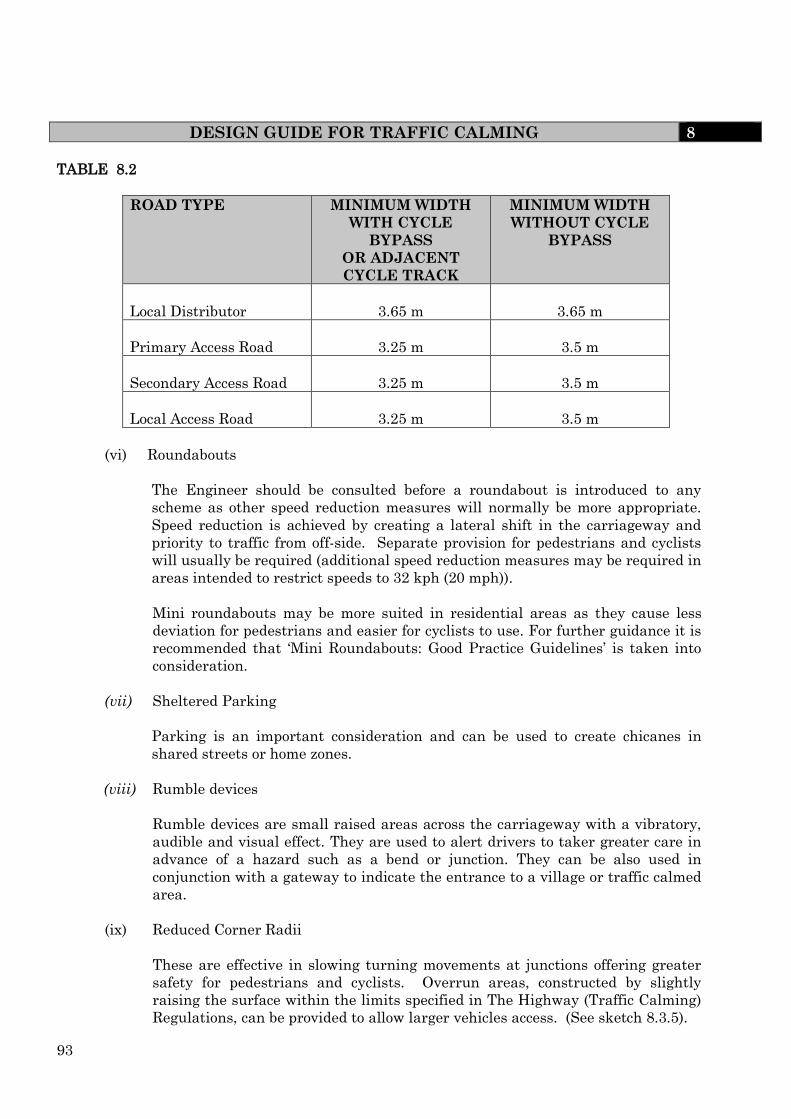
93
DESIGN GUIDE FOR TRAFFIC CALMING 8
TABLE 8.2
ROAD TYPE
MINIMUM WIDTH
WITH CYCLE
BYPASS
OR ADJACENT
CYCLE TRACK
MINIMUM WIDTH
WITHOUT CYCLE
BYPASS
Local Distributor
3.65 m
3.65 m
Primary Access Road
3.25 m
3.5 m
Secondary Access Road
3.25 m
3.5 m
Local Access Road
3.25 m
3.5 m
(vi) Roundabouts
The Engineer should be consulted before a roundabout is introduced to any
scheme as other speed reduction measures will normally be more appropriate.
Speed reduction is achieved by creating a lateral shift in the carriageway and
priority to traffic from off-side. Separate provision for pedestrians and cyclists
will usually be required (additional speed reduction measures may be required in
areas intended to restrict speeds to 32 kph (20 mph)).
Mini roundabouts may be more suited in residential areas as they cause less
deviation for pedestrians and easier for cyclists to use. For further guidance it is
recommended that ‘Mini Roundabouts: Good Practice Guidelines’ is taken into
consideration.
(vii) Sheltered Parking
Parking is an important consideration and can be used to create chicanes in
shared streets or home zones.
(viii) Rumble devices
Rumble devices are small raised areas across the carriageway with a vibratory,
audible and visual effect. They are used to alert drivers to taker greater care in
advance of a hazard such as a bend or junction. They can be also used in
conjunction with a gateway to indicate the entrance to a village or traffic calmed
area.
(ix) Reduced Corner Radii
These are effective in slowing turning movements at junctions offering greater
safety for pedestrians and cyclists. Overrun areas, constructed by slightly
raising the surface within the limits specified in The Highway (Traffic Calming)
Regulations, can be provided to allow larger vehicles access. (See sketch 8.3.5).

94
DESIGN GUIDE FOR TRAFFIC CALMING 8
(x) Overrun areas
Overrun areas are used at bends and junctions (including roundabouts). They
are areas of carriageway with a surface texture and/or appearance intended to
deter overrunning by cars and other light vehicles. Their purpose is to allow the
passage of large vehicles, such as buses and refuse vehicles, while maintaining
‘tight’ carriageway dimensions that deter smaller vehicles from speeding.
However they should generally be avoided in residential and mixed-use streets.
They can:
interfere with pedestrian desire lines
pose a hazard for cyclists.
Constructed by slightly raising the surface within the limits specified in The
Highway (Traffic Calming) Regulations, can be provided to allow larger vehicles
access. (See sketch 8.3.5).
(xi) Speeding/Red Light Camera/Vehicle Activated Devices
These should not be required if the road layout has been suitably designed,
however it is conceivable that in some situations it may be necessary to
provide a site for a camera. They reduce speed through heightened awareness
of the speed limit local to the camera.
KEY TO APPENDIX 8.1
traffic calming measures which could be considered for roads classified using the
road hierarchy.
() only if the speed limit is 48 kph (30 mph) or less and the scheme is approved by
the Engineer.
x traffic calming measures which are not suitable for roads classified using the
road hierarchy.
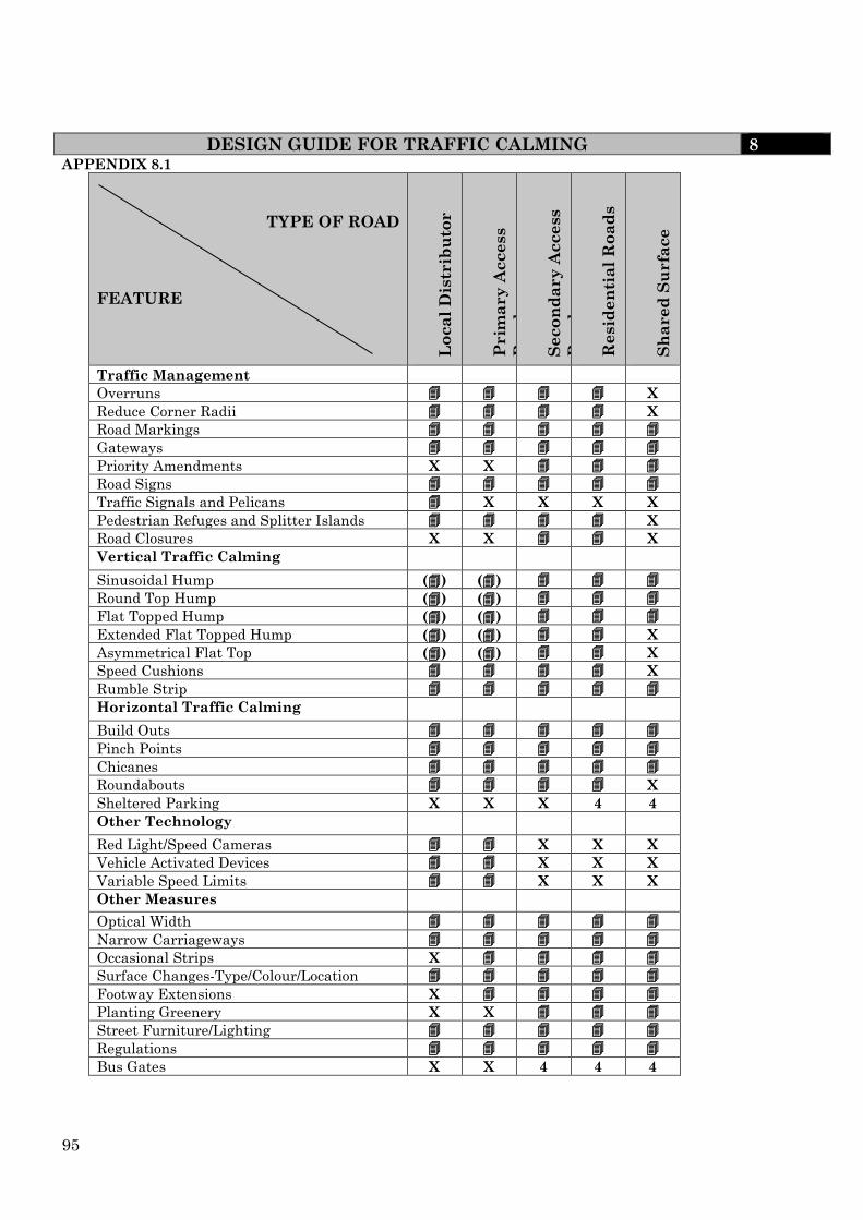
95
DESIGN GUIDE FOR TRAFFIC CALMING 8 APPENDIX 8.1
TYPE OF ROAD
FEATURE
Lo
ca
l D
istr
ibu
tor
Prim
ary
Access
Ro
ad
S
eco
nd
ary
Access
Ro
ad
R
esid
en
tia
l R
oa
ds
Sh
ared
Su
rfa
ce
Traffic Management
Overruns X
Reduce Corner Radii X
Road Markings
Gateways
Priority Amendments X X
Road Signs
Traffic Signals and Pelicans X X X X
Pedestrian Refuges and Splitter Islands X
Road Closures X X X
Vertical Traffic Calming
Sinusoidal Hump () ()
Round Top Hump () ()
Flat Topped Hump () ()
Extended Flat Topped Hump () () X
Asymmetrical Flat Top () () X
Speed Cushions X
Rumble Strip
Horizontal Traffic Calming
Build Outs
Pinch Points
Chicanes
Roundabouts X
Sheltered Parking X X X 4 4
Other Technology
Red Light/Speed Cameras X X X
Vehicle Activated Devices X X X
Variable Speed Limits X X X
Other Measures
Optical Width
Narrow Carriageways
Occasional Strips X
Surface Changes-Type/Colour/Location
Footway Extensions X
Planting Greenery X X
Street Furniture/Lighting
Regulations
Bus Gates X X 4 4 4

96
DESIGN GUIDE FOR TRAFFIC CALMING 8
Notes
1. Narrower cushions should be 65mm high.
1600mm - 1700mm for bus route; up to 2000mm elsewhere
Within chicanes narrower widths may be appropriate
3700mm maximum
a) 3500mm may be appropriate for routes with mini buses
b) About 2000mm to 3000mm on other routes
Not steeper than 1 in 15
Tra
ffic
d
ire
ction
75mm max. Not steeper than 1 in 8
DETAIL
1.0
m
Kerbline
Ca
rria
ge
wa
y h
alf w
idth
pre
ferr
ed
1.0m preferred 0.75m min.
Build-out to protect cycle gap from parking
Wider carriageway will require additional speed cushions
Typical Layout
Sketch No 8.2.1 SPEED CUSHION
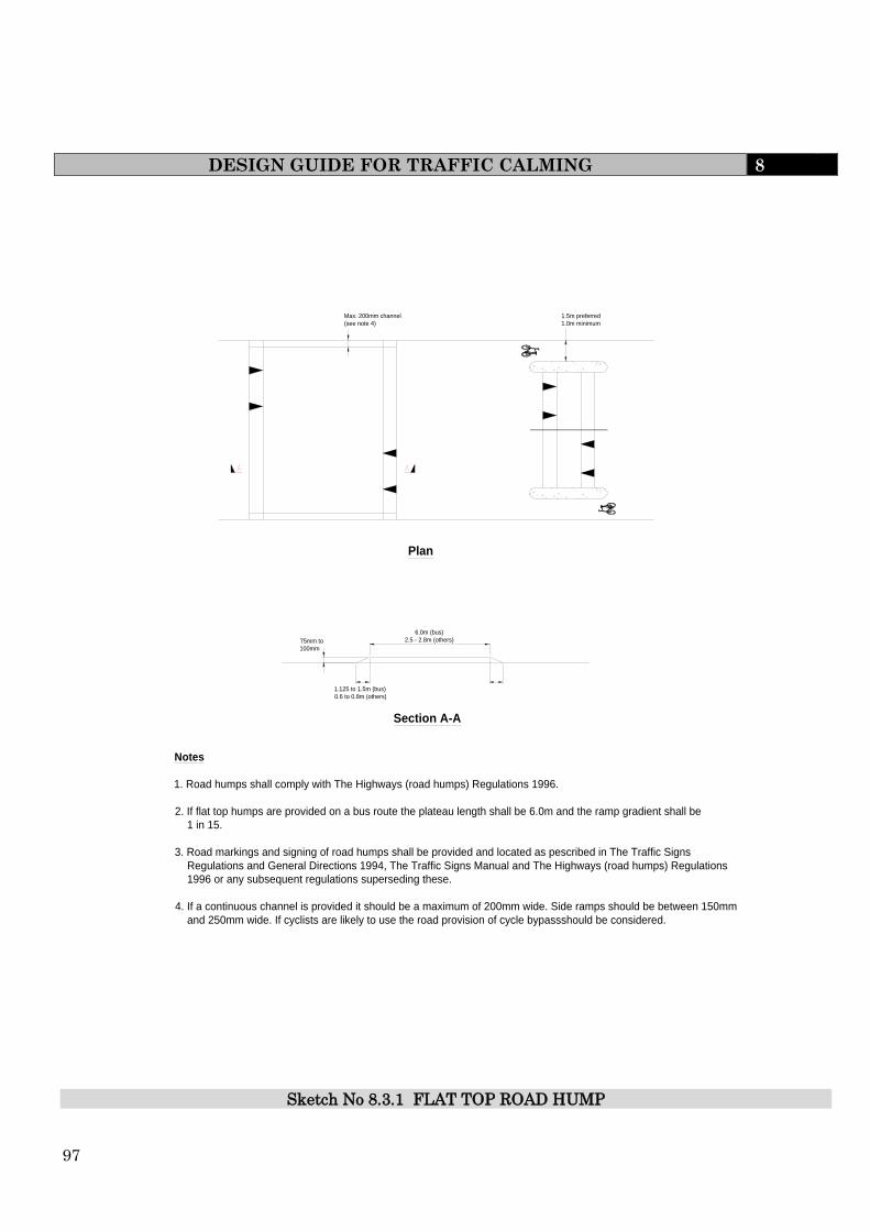
97
DESIGN GUIDE FOR TRAFFIC CALMING 8
Sketch No 8.3.1 FLAT TOP ROAD HUMP
Notes
1. Road humps shall comply with The Highways (road humps) Regulations 1996.
2. If flat top humps are provided on a bus route the plateau length shall be 6.0m and the ramp gradient shall be
1 in 15.
3. Road markings and signing of road humps shall be provided and located as pescribed in The Traffic Signs
Regulations and General Directions 1994, The Traffic Signs Manual and The Highways (road humps) Regulations
1996 or any subsequent regulations superseding these.
4. If a continuous channel is provided it should be a maximum of 200mm wide. Side ramps should be between 150mm
and 250mm wide. If cyclists are likely to use the road provision of cycle bypassshould be considered.
Section A-A
6.0m (bus)
2.5 - 2.8m (others)
1.125 to 1.5m (bus)
0.6 to 0.8m (others)
75mm to
100mm
Max. 200mm channel
(see note 4)
1.5m preferred
1.0m minimum
Plan

98
DESIGN GUIDE FOR TRAFFIC CALMING 8
ROUND TOP HUMP (TAPERED SIDED) - PLAN VIEW
3.7
metr
es
1850
750
Solid White Line (See TAL 7/96)
Kerb
White "STAMARK" or similar approved
h =
Kerb Channel
200mm 200mm Slope distance 3h
h
ROUND TOP HUMP (TAPERED SIDED) - TRANSVERSE
SECTION
h = 25 millimeters (min.) 100 millimeters (max.) (Constant profile across width)
h
3.7 metres (min.)
Road surface Edge of hump
Segment of circle
Direction of Traffic
ROUND TOP HUMP - LONGITUDINAL SECTION
Notes This hump normally extends across the road from kerb to kerb. A permitted variant is shown in the diagram below.
Edge of hump
25 millimeters (min.) 100 millimeters (max.) (Constant profile across width)
Road surface
Sketch No 8.3.2 ROUND TOP ROAD HUMPS

99
DESIGN GUIDE FOR TRAFFIC CALMING 8
Notes for Sketch 8.3.3
(a) The approaches to and exits from bypasses of road narrowing should ideally be
protected from parked vehicles within 20m. Where parked vehicles would
otherwise be anticipated to block the gap for cyclists, this can be avoided by use
of build-outs, parking restrictions or a mandatory cycle lane. If a mandatory
cycle lane is not used than an advisory cycle lane is recommended.
Priority System
(b) Provide alternating priority for vehicles where a number of narrowings are
proposed, except on a gradient when priority may be given to the uphill
direction.
(c) Ensure that the gap provided for cyclists allows for growth of any adjacent
vegetation.
(d) For details of speed cushions see Sketch 8.2.1.
Central Island
(e) It is recommended that central islands only be used to cater for particular
pedestrian crossing movements.
(f) Where the design speed is less than 40 kph (25 mph) and the vehicle flow is
expected to be light then a maximum carriageway width of 3.0m is
recommended. Where the design speed is greater than 40kph (25 mph) and/or
where wide vehicles are expected to be common then the minimum carriageway
width shall be 4.5m around the central island.
(g) The speed reducing effect of traffic islands is usually only slight. Other features
such as speed cushions and road humps should be considered in order to reduce
speed.
(h) Where a refuge is provided on a hill, narrowing the gap downhill can assist
uphill cyclists by increasing the width available.
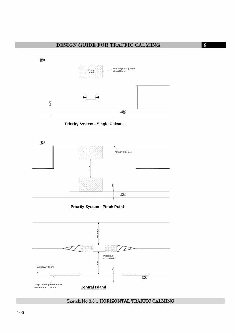
100
DESIGN GUIDE FOR TRAFFIC CALMING 8
Sketch No 8.3 1 HORIZONTAL TRAFFIC CALMING
Chicane
Island
1.5
m
Max. height of any visual
object 600mm
Priority System - Single Chicane
1.5
m
Priority System - Pinch Point
3.0
m
Advisory cycle lane
1.5
m
Central Island
4.5
mS
ee
no
te 6
Advisory cycle lane
Pedestrian
crossing point
Kerb provided to prevent vehicles
encroaching on cycle lane

101
DESIGN GUIDE FOR TRAFFIC CALMING 8
Sketch No 8.3.4 CHICANE STAGGER LENGTHS
Free view width (A) – the width of the central gap between build-outs on opposite sides.
Lane width (B) – the average width between the build-out and the opposite kerb.
Stagger length (L) – the length between the start of the stagger on the offside and the end of
the stagger on the nearside.
Path angle – the angle through which the traffic lane is displaced.
Stagger length and car speeds
Lane width ‘B’
(metres)
Free view width
‘A’ (metres)
Stagger length ‘L’ to achieve required vehicle
speed in chicane (metres)
15 mph 20 mph 25 mph
3.0 +1.0 6 9 14
0.0 9 13 18
–1.0 12 16 -
3.5 +1.0 - - 11
0.0 9 12 15
–1.0 11 15 19
4.0 +1.0 - 7 9
0.0 - 9 12
–1.0 - 11 15
Minimum dimensions of stagger length for larger vehicles at very low speeds
Lane width ‘B’
(metres)
Stagger length ‘L’ needed for a free view width of 0.0 metre (metres)
Articulated lorry Rigid lorry Single deck
bus
3.0 20 12 13
3.5 15 9 11

102
4.0 11 7 9
DESIGN GUIDE FOR TRAFFIC CALMING 8
Sketch No. 8.3.5 OVERRUN AREAS FOR REDUCED RADII CORNERS
Notes
1. Maximum slope of overrun area to be 1 in 4.
2. No vertical face to be greater than 6mm.
6.0m or
4.0m
Plan
Surface Course
Binder Course
Base (road base)
Sub-Base
15mm max. (see note 2)
Section A-A

103
DESIGN GUIDE FOR CYCLE FACILITIES 9
9.0 CYCLING FACILITIES
9.1 INTRODUCTION
Cycling is recognised in the NNPF as a sustainable mode to be encouraged in new
development. Cyclists should generally be accommodated on the carriageway. In areas
of low traffic volume and low speeds there should not be the need for dedicated cycle
lanes on the street. However the Developer shall liase with the Engineer to establish
the requirements in regard to the provision of cycling infrastructure and links into the
existing cycling network.
9.2 DEFINITION OF A CYCLE TRACK
“Cycle track” means a way independent of an existing highway, over which the public
have a right of way on pedal cycles with or without a right of way on foot (as defined in
section 329(1) of the Highways Act 1980, and as amended by Section 1(1) of the Cycle
Tracks Act 1984)
9.3 LAYOUT
It is important that pedestrian and cyclist networks offer direct routes that help to
encourage walking and cycling for local trips. Cycle access should always be considered
on links between streets that are not available to motor traffic.
To make the best of the benefit to security arising from human activity, pedestrian and
cycle routes within new developments can be set out to follow the road network. Routes
away from roads for non-motorised users should be well lit, overlooked by properties
and not include features that can create hiding places and thus compromise security.
Pedestrian facilities should normally be provided alongside cycle tracks and segregation
between cyclists and pedestrians should preferably be achieved by a surface colour
differentiation together with the use of a 150 mm wide white line.
Where cycle-specific facilities are provided the geometry and visibility should be in
accordance with the design speed, normally 30km/h (20mph). This can be reduced when
it is necessary for cyclists to go at a lower speed.
It should also be taken into consideration that cyclists are more likely to choose routes
that enable them to keep moving. Routes that take them away from their desire lines
and require them to concede priority to side-road traffic are less likely to be used.
Evidence suggests that cyclists using cycle tracks running adjacent and parallel to a
main road are particularly vulnerable when they cross the mouths of side roads and
that, overall, these routes can be more hazardous to cyclists than the equivalent on-road
route.
Tactile paving and markings are to be provided in accordance with current DFT
guidance.
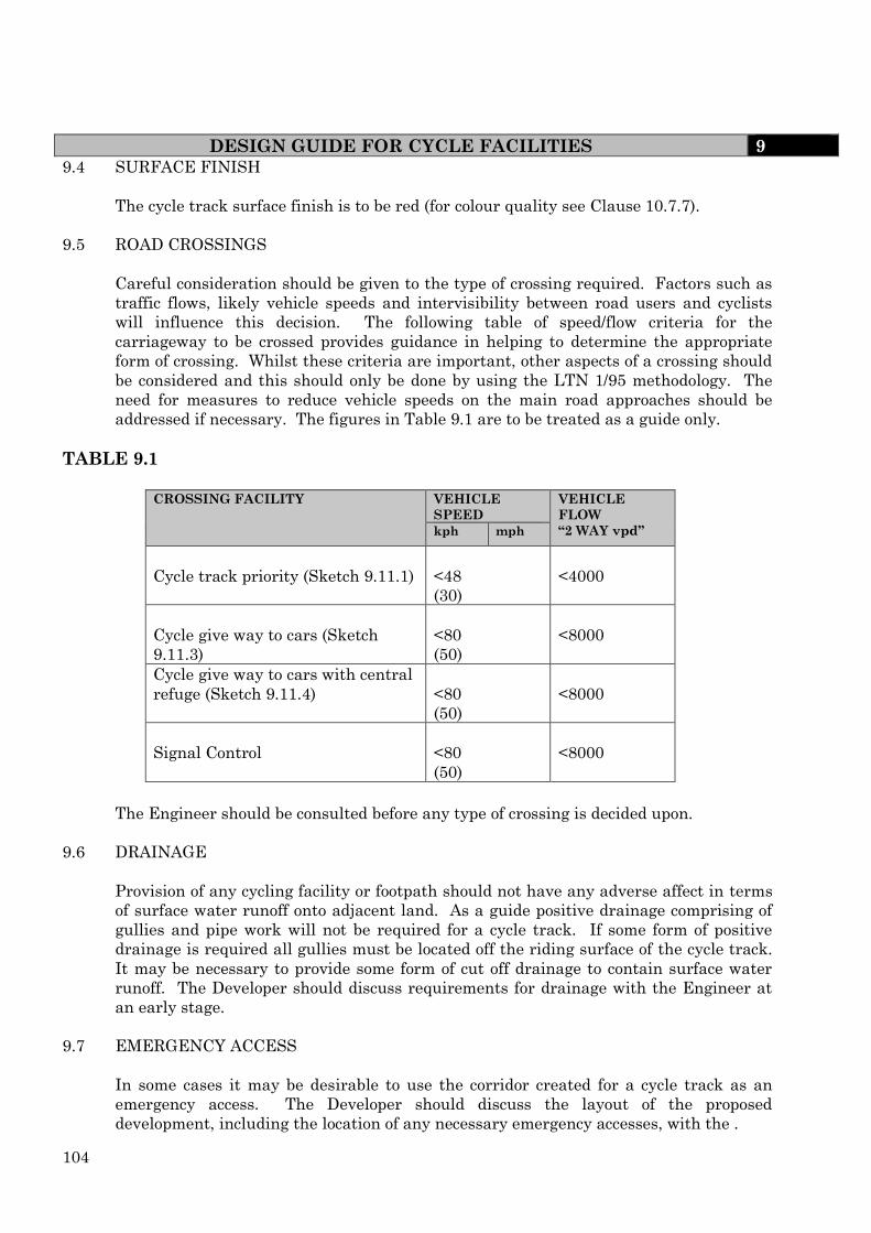
104
DESIGN GUIDE FOR CYCLE FACILITIES 9 9.4 SURFACE FINISH
The cycle track surface finish is to be red (for colour quality see Clause 10.7.7).
9.5 ROAD CROSSINGS
Careful consideration should be given to the type of crossing required. Factors such as
traffic flows, likely vehicle speeds and intervisibility between road users and cyclists
will influence this decision. The following table of speed/flow criteria for the
carriageway to be crossed provides guidance in helping to determine the appropriate
form of crossing. Whilst these criteria are important, other aspects of a crossing should
be considered and this should only be done by using the LTN 1/95 methodology. The
need for measures to reduce vehicle speeds on the main road approaches should be
addressed if necessary. The figures in Table 9.1 are to be treated as a guide only.
TABLE 9.1
CROSSING FACILITY
VEHICLE
SPEED
VEHICLE
FLOW
“2 WAY vpd” kph mph
Cycle track priority (Sketch 9.11.1)
<48
(30)
<4000
Cycle give way to cars (Sketch
9.11.3)
<80
(50)
<8000
Cycle give way to cars with central
refuge (Sketch 9.11.4)
<80
(50)
<8000
Signal Control
<80
(50)
<8000
The Engineer should be consulted before any type of crossing is decided upon.
9.6 DRAINAGE
Provision of any cycling facility or footpath should not have any adverse affect in terms
of surface water runoff onto adjacent land. As a guide positive drainage comprising of
gullies and pipe work will not be required for a cycle track. If some form of positive
drainage is required all gullies must be located off the riding surface of the cycle track.
It may be necessary to provide some form of cut off drainage to contain surface water
runoff. The Developer should discuss requirements for drainage with the Engineer at
an early stage.
9.7 EMERGENCY ACCESS
In some cases it may be desirable to use the corridor created for a cycle track as an
emergency access. The Developer should discuss the layout of the proposed
development, including the location of any necessary emergency accesses, with the .

105
DESIGN GUIDE FOR CYCLE FACILITIES 9
Engineer at an early stage so that, if necessary, the cycle track can be designed to accommodate
emergency vehicles.
9.8 MEASURES TO PREVENT ABUSE BY MOTOR VEHICLES
The developer shall provide physical measures to prevent motor vehicles gaining access
to any cycle track. The Developer should have early discussions with the Engineer to
ascertain physical measures which will be suitable in particular locations
9.9 CYCLE PARKING
All cycle parking should be in accordance with Section 7.
9.10 DESIGN STANDARDS
The following standards shall apply: -
(i) Cycle Tracks
(a) Minimum radius of curvature should be 25m on Commuter routes where
the design speed is 20mph and 15m on Local Access routes where the
design speed is 15mph..
(b) Minimum desirable sight line distance is 25m on Commuter routes where
the design speed is 20mph and 15m on Local Access routes where the
design speed is 15mph. When considering curvature and sight line
distances site specific details such as gradient and surface quality should
be taken into consideration.
(c) Desirable crossfall should be between 1% and 2.5%, the cycle track should
always fall towards the inside of on bends.
(d) Gradients should be -3% maximum over unrestricted lengths
-5% maximum over lengths up to 100m
-7% maximum over lengths up to 30m
note -in exceptional circumstances gradients
exceeding 7% are acceptable over shorter
lengths.
(e) For a 2-way independent cycle route the width required is 3m.
(f) Minimum desirable lateral clearance 0.5m, desirable minimum
headroom 2.7m.
(g) Visibility standards where cycle tracks cross roads shall be in accordance
with Table 9.2. There shall be no relaxation of the ‘y’ distance. The ‘x’
distance should be 9m however in difficult circumstances it may be
reduced to 4.5m providing an upright ‘Give Way’ sign (Diag. 602) is
provided on the cycle track. Only in exceptional circumstances will an ‘x’

106
DESIGN GUIDE FOR CYCLE FACILITIES 9
distance of less than 4.5m be allowed. In this case an upright ‘Stop’ sign
(Diag 601.1) must be provided (note this will require DFT approval which
may be a lengthy procedure and will be at the Developer’s expense).
Further details are available in TD42/95. Early consultation with the Engineer is
recommended.
Further guidance can be found in the LTN “Cycling Infrastructure Design”
TABLE 9.2 DESIGN SPEED OF ROAD
kph mph
‘y’ DISTANCE
(m)
16 10 11
32 (20) 25
40 (25) 33
50 (30) 45
60 (40) 59
(ii) Combined Cycle Tracks/Footpaths
(a) The minimum combined width shall be 3.3 metres (between restrains). Further
guidance on suitable widths for combined facilities is given in Local Transport
Note: 2/04 “Adjacent and Shared Use Facilities for Pedestrians and Cyclists”.
(b) Signage in accordance with The Traffic Signs Regulations and General
Directions 2002 and the Traffic Signs Manual to be provided to show shared
usage.
9.11 STREET FURNITURE AND LANDSCAPING
Where cyclists lean into a bend, their body may extend over the inner edge of a cycle
track. Poles, fences or other vertical features on the inside of bends should therefore be
set back by 0.5m and any overhanging tree branches cleared.
The area adjacent to a cycle track has an impact on personal security. Landscaping and
planting should not impede forward visibility or passive surveillance from surrounding
properties, nor create hiding places close to a path. A verge or clear area ideally not less
than 1.0m wide may be provided on each side of a track, and planting near the track
kept below 800mm height. Vegetation that is likely to grow higher may be set further
back.
Any planting adjacent to a cycle track should be designed not to cause punctures to
pneumatic cycle tyres subsequent to trimming or windfall whilst still providing a
substantial visual and physical barrier if required. All landscape proposals should be in
accordance with Section 13. The proposals shall be submitted to the Engineer for
approval.

107
DESIGN GUIDE FOR CYCLE FACILITIES 9 9.12 GENERAL
(i) Construction Details are to comply with the requirements of Section 10.
(ii) Street lighting is to be provided in accordance with Section 11 with additional
lighting at intersections with other traffic routes. The scheme is to be submitted
to the Engineer for approval.
(iii) Traffic signs and road markings are to be provided and located as prescribed in
The Traffic Signs Regulations and General Directions 2002 and the Traffic Signs
Manual. The proposals are to be submitted to the Engineer for approval.
(iv) The Developer shall seek advice from the Engineer in respect to the form of all
crossings and junctions. See also sketches 9.11.1 to 9.11.4 and Clause 9.3.
(v) Any proposals that require the construction of subways or retaining walls must
be discussed with the Engineer and comply with ‘The Technical Approval
Procedure for Developers Structures’ (see Clause 4.9).

108
DESIGN GUIDE FOR CYCLE FACILITIES 9
Cycle Track Priority Crossing
Notes for Sketch 9.11.1
(a) A cycle track priority road crossing should only be used for crossing single carriageway
roads where the anticipated vehicle flow is less than 4000 vehicles per day and vehicle
speed is physically restricted to less than 48 kph (30 mph).
(b) The flat top road hump should be constructed in a contrasting colour or material to give
prominence to the traffic calming feature. The road hump design and location must
comply with the Road Hump Regulations, including signing requirements.
(c) This facility will require reasonable visibility between the cycle track and the
carriageway dependent upon the circumstances at a particular location. Reasonable
visibility will therefore be provided between the cycle track and the footway and thus it
is unlikely that sign Diag. No.963.1 will be necessary.
(d) The maximum permitted height of a road hump is 100mm, and kerbs are generally
125mm. Providing a level crossing may necessitate dropping the kerb line slightly.
(e) This detail shows an arrangement to give cyclists priority to cross a minor road. In
choosing such an arrangement developers should be aware that this does not accord the
same priority to pedestrians.
(f) Diag No.950 is shown on this drawing to illustrate the range of circumstances in which
it can usually be employed. In practice, it will normally be sited at a greater distance
from the feature than it has been possible to show in the drawing. Advice is given in
Chapter 4 of the Traffic Signs Manual. Note that the distance on plate Diag No.572
should be in yards.
(g) Diag No. 7014 ‘Changed Priorities Ahead’ may be used on the approaches to the
crossing when relevant.
(h) Tactile paving and markings are to be provided in accordance with current DTLR
guidance.
(i) Traffic signs and road markings are to be to the satisfaction of the Engineer and are to
be provided and located as prescribed in the Traffic Signs Regulations and General
Directions 2002 and the Traffic Signs Manual or any subsequent superseding
regulations.
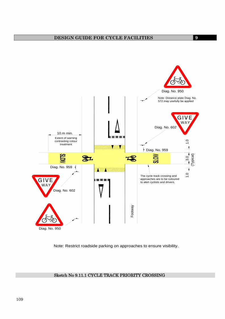
109
DESIGN GUIDE FOR CYCLE FACILITIES 9
Sketch No 9.11.1 CYCLE TRACK PRIORITY CROSSING
3.0
1.0
1.0
10.m min.
(Typ
ica
l)
Diag. No. 959
Diag. No. 959
Extent of warning
contrasting colour
treatment
The cycle track crossing and
approaches are to be coloured
to alert cyclists and drivers.
Diag. No. 950
Note: Distance plate Diag. No.
572 may usefully be applied
Diag. No. 602
Diag. No. 602
Diag. No. 950
Foo
twa
y
Note: Restrict roadside parking on approaches to ensure visibility.
110
DESIGN GUIDE FOR CYCLE FACILITIES 9 Cycle Track Priority Crossing “Bending Out” at Minor Road
Notes for Sketch 9.11.2
(a) Cycle track priority road crossings should only be used where anticipated vehicle flows
are less than 4000 vehicles per day and vehicle speed is physically restrained to less
than 48kph (30 mph).
(b) The flat top road hump should be constructed in a contrasting colour or material to give
prominence to the traffic calming feature. The road hump design and location must
comply with the Road Hump Regulations, including signing requirements.
(c) The maximum permitted height of a road hump is 100mm, and kerbs are generally
125mm. Providing a level crossing may necessitate dropping the kerb line slightly.
(d) If visibility between the footway and cycle track is restricted, sign Diag No. 963.1 may
be necessary.
(e) It is important for safety that the “bend out” is designed so as to provide the cyclist with
a straight approach to the crossing. The cycle path should not be deflected through an
angle greater than 45° and should not give the cyclist the feeling of a detour.
(f) Advice on the siting of sign Diag No. 950 is given in Chapter 4 of the Traffic Signs
Manual.
(g) Diag No.7014 “Changed Priorities Ahead” may be used on the approaches to the
crossing when relevant.
(h) Where build-outs or flat top road humps are constructed the highway drainage
requirements must be considered.
(i) This detail shows an arrangement to give cyclists priority to cross a minor road. In
choosing such an arrangement developers should be aware that this does not accord the
same priority to pedestrians.
(j) Tactile paving and markings are to be provided in accordance with current DTLR
guidance.
(k) Traffic signs and road markings are to be to the satisfaction of the Engineer and are to
be provided and located as prescribed in the Traffic Signs Regulations and General
Directions 2002 and the Traffic Signs Manual or any subsequent superseding
regulations.

111
DESIGN GUIDE FOR CYCLE FACILITIES 9
Sketch No. 9.11.2 CYCLE TRACK CROSSING BENDING OUT’ AT MINOR ROAD
Diag. No. 950Note: Distance plate
Diag. No. 572 may
usefully be applied
Diag. No. 602
Diag.
No. 602
Restricted roadside parking to
ensure visibility
Deflection to take account
of visibility requirements
and speed of cyclists
Area to be kept clear
for visibility
The 4.0m min. set back
may be achived by
build-outs where highway
limits are constrained
Build-outs can help ensure
the crossing is in line with
the cycle track/footway
Diag. No. 950
Diag. No. 957
Diag. No. 957
Minor road
Alternative: In Line Cycle Track
Crossing, Giveway.
Where there is insufficient space to
construct a 'bend out' then a flat top road
hump in line with the cycle track/footway
may be suitable. This will require Give Way
markings for the cyclist.
4.0 min.
8.0 max.

112
DESIGN GUIDE FOR CYCLE FACILITIES 9 Cycle Track Give Way Crossing
Notes for Sketch 9.11.3
(a) Where anticipated traffic flows are less than 4000 vehicles per day on a single
carriageway the cycle track priority crossing should be considered.
(b) This detail is not suitable for anticipated vehicle flows greater than 6000 vehicles per
day or where anticipated speeds are greater than 80kph (50 mph).
(c) If visibility between the cycle track and the footway is inadequate and it is not possible
to incorporate measures to improve visibility then traffic sign Diag No.963.1 may be
necessary to advise pedestrians of a cycle track crossing. Unnecessary use of this will
cause sign clutter.
(d) Where visibility is poor it is preferable to use all the signs and markings available for
the Give Way (Diag No.s 602, 1003 and 1023) for the cyclist rather than a
barrier/chicane.
(e) Diag No.950 is shown on this drawing to illustrate the range of circumstances in which
it can usually be employed. Its location is diagrammatic only. Advice is given in
Chapter 4 of the Traffic Signs Manual.
(f) Where carriageway width permits, it may be advantageous to provide a central refuge.
This will benefit both cyclist and pedestrian safety.
(g) Tactile paving and markings are to be provided in accordance with current DTLR
guidance.
(h) Traffic signs and road markings are to be to the satisfaction of the Engineer and are to
be provided and located as prescribed in the Traffic Signs Regulations and General
Direction 2002 and the Traffic Signs Manual or any subsequent superseding
regulations.

113
DESIGN GUIDE FOR CYCLE FACILITIES 9
Min. 1.0m Extent of warning contrasting colour
treatment
Drop kerb arrangement
Build-out
Sketch No 9. 11.3 CYCLETRACK GIVEWAY CROSSING

114
DESIGN GUIDE FOR CYCLE FACILITIES 9 Cycle Track Crossing with Refuge Island
Notes for Sketch 9.11.4
(a) In urban areas, this detail is suitable for all road categories up to and including
Primary Access Roads. This detail may also be suitable for all single carriageway roads
with anticipated traffic flows less than 8,000 vehicles per day.
(b) If visibility between the cycle track and the footway is inadequate and it is not possible
to incorporate measures to improve visibility then traffic sign Diag No.963.1 may be
necessary to advise pedestrians of a cycle track crossing.
(c) Where visibility is poor it may be preferable to use all the signs and markings available
for the Give Way (Diag No.s 602,1003 and 1023) for the cyclist rather than a
barrier/chicane.
(d) Where the design speed is less than 40kph (25mph) and the anticipated vehicle flow is
light then a maximum carriageway width of 3.0m is recommended. Where the design
speed is greater than 40kph (25mph) and/or where wide vehicles are expected to be
common then the minimum carriageway width shall be 4.5m around the central island.
(e) Generally the crossing area within the refuge should have a longitudinal width between
3.0m and 4.0m (absolute minimum 2.5m) to accommodate groups of cyclists and should
be flush with the adjacent carriageway.
(f) Diag No.950 is shown on this sketch to illustrate the range of circumstances in which it
can usefully be employed. Its location is diagrammatic only. Advice is given in Chapter
4 of the Traffic Signs Manual.
(g) Where pedestrian flows on the footway are high it may be advantageous to bend out the
footway (as shown), or provide a build-out (see Sketch 9.11.3). This will allow cyclists to
wait at the Give Way line without impeding pedestrians. If this is not feasible then the
Give Way lines can be placed at the back of the footway.
(h) Segregation on the immediate approaches to the crossing may not be appropriate in all
circumstances. Consideration may be given to the inclusion of Give Way lines within
the refuge.
(i) Tactile paving and markings are to be provided in accordance with current DTLR
guidance.

115
DESIGN GUIDE FOR CYCLE FACILITIES 9
Sketch No 9.11.4 CYCLE TRACK CROSSING WITH REFUGE ISLAND
Min. 1.0m
Extent of warning
contrasting colour
treatment
Diag. No. 956
Diag. No. 950Note: Distance plate
Diag. No. 572 may
usefully be applied
Fo
otw
ay
Diag. No. 957
Diag. No. 950
Fo
otw
ay
The cycle track/footpath approaches
to the edge of carriageway are to be
coloured to alert cyclists
Footway bendout
Drop kerb arrangement
Note: Drop kerb at crossing point
to be flush with carriageway
Level difference of Raised white line
delineator Diag. No. 1049.1
2.0m preferred
(1.8m minimum)
116
DESIGN GUIDE FOR CYCLE FACILITIES 9 Access Barriers
Notes for Sketch 9.11.5
(a) Bollards should be the first choice to discourage access by motor vehicles. If
motorcycles subsequently become a nuisance then more restrictive forms of barrier
should be considered.
(b) Wheelchair users negotiating the access barrier may need to swing under the barriers
when turning. The barriers on the wheelchair bypass should therefore comprise a single
rail with a 700mm clearance to the ground. Fences/walls etc. adjoining the wheelchair
bypass must meet it at one of the corners, and free space to a distance of 450mm outside
these rails should be provided.
(c) The barriers in the sketch are shown constructed in tubular steel.
(d) All steelwork is to be provided with adequate corrosion protection to the satisfaction of
the Engineer.
(e) Consideration must be given to the visibility of bollards and barriers so that they do not
cause a hazard to path users. The use of high visibility paints or signs may be
necessary.
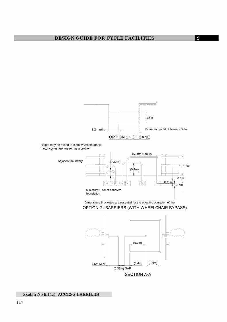
117
DESIGN GUIDE FOR CYCLE FACILITIES 9
0.5m MIN (0.4m)
(0.7m)
(0.9m)
(0.38m) GAP
150mm Radius
Height may be raised to 0.5m where scramble motor cycles are forseen as a problem
Adjacent boundary
Minimum 150mm concrete foundation
OPTION 2 : BARRIERS (WITH WHEELCHAIR BYPASS)
SECTION A-A
Dimensions bracketed are essential for the effective operation of the barrier
OPTION 1 : CHICANE
1.2m min. Minimum height of barriers 0.8m
0.3m
1.2m
0.15m 0.15m
(0.7m)
(0.32m)
1.5m
Sketch No 9.11.5 ACCESS BARRIERS

118
SPECIFICATION FOR ROAD AND FOOTPATH CONSTRUCTION 10
10 ROAD AND FOOTPATH CONSTRUCTION
10.1 GENERAL
Ground Site Investigation Report
(i) General - The Developer shall procure a site investigation that shall include a
desk study, walk over study, ground investigation, relevant in-situ and
laboratory testing, investigation of contamination (if indicated by the desk
study), reports of all factual findings and a report interpreting the findings
together with the appropriate advice.
The desk study shall aim to determine to past history of the area of interest
and all known knowledge relevant to the design and construction of a
highway and its associated works (BS5930:1999:6.2, BRE Special Digest 1:5.2,
BRE Digest 318).
The desk study, walk over study, planning of a ground investigation,
selection of appropriate in-situ and laboratory testing, planning of an
investigation of anticipated contamination, and the interpretation of the
findings, including assessment of CBR design values, slope sustainability and
settlement calculations where appropriate, and assessment of the Aggressive
Chemical Environment for Concrete (ACEC) for use in BRE Special Digest 1
together with advice shall be performed by a geotechnical specialist and if
indicated by the desk study supported by a geo-environmental specialist.
The ground investigation shall be performed in accordance with the current
version of BS5930, using drillers accredited by the British Drilling Association
(BDA).
The testing of soils shall be performed in accordance with the current version
of BS 1377, by a laboratory currently holding the appropriate accreditation
by the United Kingdom Accreditation Service (UKAS).
(ii) Aggressive Ground Conditions - the site investigation and related testing
shall be performed in such a manner as to enable the site classification for
Aggressive Chemical for Concrete (ACEC) to be obtained.
BRE Special Digest 1 - “Concrete in Aggressive Ground - Part 1: Assessing the
aggressive chemical environment” gives guidance on the site investigation
and related testing to enable the site classification to be achieved.
(iii) Formation Strength Determination by California Bearing Ratio - Where there
is a requirement for carriageway construction design (Clause 5.2.14 and
Table 5.2.2 the sub-grade formation strength shall be determined by
California Bearing Ration (CBR) in accordance with the method for
undisturbed samples in accordance with BS 1377. Such samples must be
taken prior to the commencement of construction activities. The positions of the
CBR samples shall be agreed with the Engineer prior to sampling and testing.

119
GENERAL 10
The number of samples taken will be such as to represent the variability and extent
of the site such that a safe and economic design can be achieved.
Samples shall be taken at the greater depth beneath the existing ground level of
either, a) 1m beneath existing ground or b) freshly exposed formation level.
Undistributed samples shall be obtained by the method given in BS 1377: Part 4:
Section 7 - clause 7.2.5 and BS 1377: Part 9: Section 2 - clause 2.4.
Testing shall be in accordance with BS 1377: Part 4: Section 7 and shall be carried
out on insitu moisture content by a UKAS Accredited Laboratory.
Note: Where the CBR testing is carried out without the involvement of the
Engineer and the Engineer considers that there is insufficient
information then a supplementary investigation will be required, at
the Developers expense, with additional CBR information obtained
as directed by the Engineer.
(iv) The ground/site investigation report shall include classification of the soil,
using the British Soil Classification System for Engineering Purposes as given
by BS5930, on which any footpath, footway or footpath/cycletrack kerb line
is to be founded. Soil classification is determined using the liquid limit,
plastic limit and plasticity index as determined by BS1377 Classification
Tests.
The soil classification will give an indication of the clay shrinkage into
categories of CH - indicating high shrinkage CI - indicating medium
shrinkage.
CL - indicating low shrinkage. The plastic limit will also determine if soils
are non-plastic which will indicate non-shrinkable soils.
Where the soil classification is determined as:-
(i) CH/CI then the depth of foundation shall be 600mm.
(ii) CL or non-plastic then the depth of foundation shall be 450mm.
Construction Thickness
The thickness of material or layers of material given in this document, shall be the
thickness after compaction and shall be determined from agreed measurements
(dips). The material thickness must comply with those specified including
tolerances, although the total minimum pavement thickness must not be less than
450mm.
Quality of Materials and Workmanship
In circumstances identified by the Engineer, certain materials, goods and
workmanship may be required to conform to a quality management scheme,
product certification scheme, have a British Board of Agreement Roads and Bridges

120
GENERAL 10
Certificate or have certification under the Highway Authorities Product Approval
Scheme. The Developer shall refer to the Department of Transport Specification for
Highway Works, Series 100, Clause 104 and Appendices A, B and C for further details.
In respect of any British Standard (BS), a BSI Kitemark Certification Scheme (if
available), all materials are required to comply with that Standard, or containers of
such materials, shall be marked with the BSI Certification Trade Mark (the
Kitemark).
The supply and laying of Asphalt materials will only be permitted by those suppliers
and contractors who have been granted accreditation under the UKAS sector 14 and 16
schemes. The developer is responsible for ensuring that any sub contractors used in this
area are suitably accredited.
The mark of conformity of any other certification body accredited by the National
Council for Certification Bodies (NACCB) or equivalent shall be an acceptable
alternative to this requirement.
The Engineer may reject any material and/or goods which do not comply with the
specified standard or which are considered “not fit for purpose”.
Note Test Certificates issued by the supplier will not normally be accepted as
providing satisfactory proof of compliance to specification. However, those test
certificates which form part of an approved quality assurance scheme may be
considered by the Engineer.
Testing of Materials
Before the commencement of works, the Engineer will require samples and/or
sample loads of the various materials and/or goods to be used in the construction
to be sampled and tested. If approved, these samples shall then be taken as
representative of the standard required by the Engineer.
The Engineer reserves the right to sample and test at any time during construction
any materials and goods that will form part of the permanent works to ensure
compliance with the specification requirements.
The Developer shall ensure that all assistance is provided to obtain any sample at
any time before or during the works.
All sampling and testing used for construction design purposes and to judge
compliance to specification shall be carried out by a laboratory which holds
United Kingdom Accreditation Service (UKAS) accreditation for the appropriate
Test method.
Where the Developer submits to the Engineer sampling and/or test certificates for
any goods or materials for which there is a requirement for UKAS accreditation
then the certificates shall be accompanied by the UKAS testing schedule for the
test laboratory and shall indicate the following:-
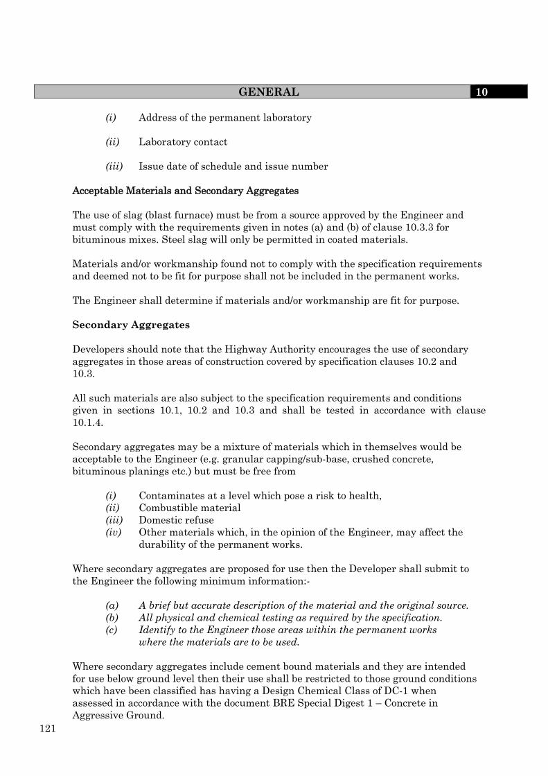
121
GENERAL 10
(i) Address of the permanent laboratory
(ii) Laboratory contact
(iii) Issue date of schedule and issue number
Acceptable Materials and Secondary Aggregates
The use of slag (blast furnace) must be from a source approved by the Engineer and
must comply with the requirements given in notes (a) and (b) of clause 10.3.3 for
bituminous mixes. Steel slag will only be permitted in coated materials.
Materials and/or workmanship found not to comply with the specification requirements
and deemed not to be fit for purpose shall not be included in the permanent works.
The Engineer shall determine if materials and/or workmanship are fit for purpose.
Secondary Aggregates
Developers should note that the Highway Authority encourages the use of secondary
aggregates in those areas of construction covered by specification clauses 10.2 and
10.3.
All such materials are also subject to the specification requirements and conditions
given in sections 10.1, 10.2 and 10.3 and shall be tested in accordance with clause
10.1.4.
Secondary aggregates may be a mixture of materials which in themselves would be
acceptable to the Engineer (e.g. granular capping/sub-base, crushed concrete,
bituminous planings etc.) but must be free from
(i) Contaminates at a level which pose a risk to health,
(ii) Combustible material
(iii) Domestic refuse
(iv) Other materials which, in the opinion of the Engineer, may affect the
durability of the permanent works.
Where secondary aggregates are proposed for use then the Developer shall submit to
the Engineer the following minimum information:-
(a) A brief but accurate description of the material and the original source.
(b) All physical and chemical testing as required by the specification.
(c) Identify to the Engineer those areas within the permanent works
where the materials are to be used.
Where secondary aggregates include cement bound materials and they are intended
for use below ground level then their use shall be restricted to those ground conditions
which have been classified has having a Design Chemical Class of DC-1 when
assessed in accordance with the document BRE Special Digest 1 – Concrete in
Aggressive Ground.

122
GENERAL 10 The Engineer may also require a sample load to be delivered for inspection and testing.
Source approval
The approval for the supply of secondary aggregates from any source shall only be given
where there is in place a QUALITY PLAN. This Quality Plan shall follow the guidance
given in the BRE DOCUMENT – QUALITY CONTROL – THE PRODUCTION OF
RECYCLED AGGREGATES.
The Quality Plan shall cover as a minimum the following areas:-
1) Acceptance criteria for the incoming material:-
i) The producer shall have and maintain procedures for acceptance of
incoming material.
ii) All statutory and regulatory requirements for the receipt of incoming
material shall be observed and included in the Acceptance Criteria.
iii) The Acceptance Criteria shall identify the types of material that every
incoming load shall have a visual inspection and gives a list of materials
which require particular attention.
iv) The visual inspection shall assess each incoming load for the
approximate percentages of sand, gravel (stony material), asphalt, wood,
glass and other foreign material such as metal, plastic, clay lumps.
v) A record of each consignment delivered and accepted shall be kept and
shall identify:-
a) date of acceptance
b) nature and quality
c) place of origin if known
d) quality by weight or volume
e) carrier
f) supplier
2) A definition of material types produced e.g. Sub-base type 1, capping, granular
fill
3) Specification requirements for the product
4) Method statement of production
This production statement shall detail the process, the process controls and the range of
products produced.
5) Inspection and testing regime
The inspection and testing regime shall be detailed. The extent of inspection and
testing

123
GENERAL 10
will be related to the finished product, the quality of the incoming material and the
production controls.
Where the finished product is intended for use as SUB-BASE TYPE 1 then the
following test regime and acceptance criteria is required:-
Test Test Method Frequency Limits
*Water absorption BS EN 1097 1/every production day 8.5% max
Grading BS EN 933 1/week SHW –
Clause
803 Type
1
Composition SHW Clause 801.6 1/week SHW
Table 8.3
Los Angeles
Fragmentation Test BS EN 1097 1/month LA50
Soundness BS 1047 1/month Comply A
& B
Frost heave SHW Clause 601 1 per 3 months 15mm
max
Plastic Limit BS1377-2 1/month Non-
Plastic
Chemical Analysis SHW Clause 801.3 1 per Month SHW
Cl801.3
After type testing as described
In Cl801.3
Note the grading and the composition for the frost heave sample shall reflect the
normal production grading and composition.
*The water absorption shall be used as a screening test. Material which has a
water absorption greater than 8.5% shall not be used as sub-base material.
All testing shall be performed by a UKAS laboratory which holds accreditation for that
test.
6) Records
Records shall be retained for all incoming materials, products and all testing
information relating to the products.
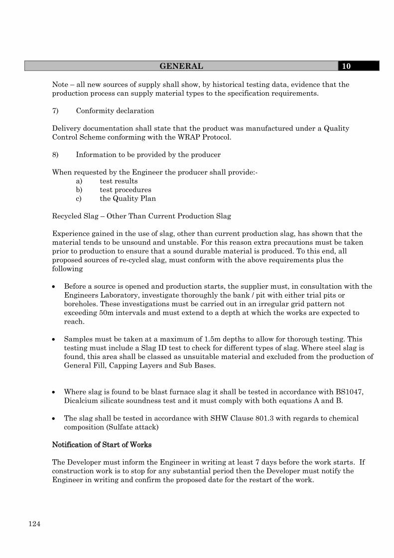
124
GENERAL 10
Note – all new sources of supply shall show, by historical testing data, evidence that the
production process can supply material types to the specification requirements.
7) Conformity declaration
Delivery documentation shall state that the product was manufactured under a Quality
Control Scheme conforming with the WRAP Protocol.
8) Information to be provided by the producer
When requested by the Engineer the producer shall provide:-
a) test results
b) test procedures
c) the Quality Plan
Recycled Slag – Other Than Current Production Slag
Experience gained in the use of slag, other than current production slag, has shown that the
material tends to be unsound and unstable. For this reason extra precautions must be taken
prior to production to ensure that a sound durable material is produced. To this end, all
proposed sources of re-cycled slag, must conform with the above requirements plus the
following
Before a source is opened and production starts, the supplier must, in consultation with the
Engineers Laboratory, investigate thoroughly the bank / pit with either trial pits or
boreholes. These investigations must be carried out in an irregular grid pattern not
exceeding 50m intervals and must extend to a depth at which the works are expected to
reach.
Samples must be taken at a maximum of 1.5m depths to allow for thorough testing. This
testing must include a Slag ID test to check for different types of slag. Where steel slag is
found, this area shall be classed as unsuitable material and excluded from the production of
General Fill, Capping Layers and Sub Bases.
Where slag is found to be blast furnace slag it shall be tested in accordance with BS1047,
Dicalcium silicate soundness test and it must comply with both equations A and B.
The slag shall be tested in accordance with SHW Clause 801.3 with regards to chemical
composition (Sulfate attack)
Notification of Start of Works
The Developer must inform the Engineer in writing at least 7 days before the work starts. If
construction work is to stop for any substantial period then the Developer must notify the
Engineer in writing and confirm the proposed date for the restart of the work.

125
GENERAL 10 Contact Details
The Developer shall supply to the Engineer all relevant contact names and telephone numbers
for emergency and out of hours work.
Quality of Work
Where Codes of Practice, British Standards or equivalent or European Standards indicate
standards of workmanship, these shall be the minimum quality of work acceptable.
Statutory Undertakers Apparatus
The Developer is advised to consult with the Statutory Undertakers regarding existing services
and for the provision of new services. The installation of all services must be completed prior to
surfacing works. Where installation occurs after surfacing works then reinstatement shall be
in accordance with Section 10.10.
Statutory Undertakers and other bodies apparatus should wherever possible be located in
verges, footpaths, footways or cycletracks and preferably laid in the following sequence from the
kerb line; telephone, other communications, water, gas, electricity in accordance with the
National Joint Utilities Group (NJUG) recommendations, unless prior approval of the Engineer
has been obtained for an alternative location.
The location of any Undertaker's apparatus above ground, or any street furniture, shall be
agreed with the Engineer.
The Developer is responsible for the satisfactory installation of all mains and
services and all associated backfilling of trenches and reinstatements within the area
to be adopted. Refer to Clauses 10.2.6, 10.10.1 and 12.4.4.
On completion of the development the Developer must, in accordance with the New Roads and
Street Works Act (NRSWA) 1991, supply to the Engineer a plan identifying the location and
position of all Statutory Undertakers apparatus.
Temporary Signs/Signals
For all works carried out within the development, the Developer shall ensure that all signing is
to the satisfaction of the Engineer and complies with Chapter 8 of the Department of
Transport's "Traffic Signs Manual". The use of temporary traffic signals shall be in full
accordance with NEHAUC agreed working procedure GN2/93/2003.
The Developer has a civil law liability to warn road users of obstructions on the highway, as
a consequence of the development.
Protection of Carriageways
The Developer shall employ mechanical equipment and/or labour to keep all roads, footpaths
and footways clean and free from dust, mud, slurry and any obstruction to the satisfaction of
the Police and Highway Authority.

126
GENERAL 10
Should the Developer fail to comply with this requirement, the Engineer will invoke Section
148 or 149 of the Highways Act 1980 (see Clause 4.6).
Protection of Highways
Any damage or subsidence to an adjoining Highway which may occur during the progress of the
works or maintenance period, attributed to any fault or careless workmanship by the
Developer, shall be made good by the Developer at their own expense to the satisfaction of the
Engineer.

127
GENERAL 10
APPENDIX 10.1 SAMPLING AND TEST METHODS IN ACCORDANCE WITH UKAS
TYPES OF SITE LOCATION MATERIALS/PRODUCTS TESTED
TYPES OF TESTS/
PROPERTIES MEASURED
RANGE OF MEASUREMENT
STANDARD SPECIFICATION
EQUIPMENT/
TECHNIQUES USED
CIVIL ENGINEERING
CONSTRUCTION SITES
AGGREGATES
Physical Tests
In-situ density
Documented In-House
Method No. CCC TP 97
Nuclear Density Meter
BITUMINOUS MIXTURES
for roads and other paved areas
Sampling
Sampling from
around the augers of the paver
Sampling coated chippings from stockpiles
BS 598: Part 100: 1987
BS 598: Part 100: 1987
CONCRETE – Fresh
Physical Tests
Slump
Air content – method A
Sampling
Sampling fresh concrete on site
Sampling from initial discharge
(slump test)
Making test cubes
BS 1881: Part 102: 1983
BS 1881: Part 106: 1983
BS 1881: Part 101: 1983
BS 1881: Part 102: 1983
BS 1881: Part 108: 1983
IN-SITU FLOORINGS – polymer
modified cementitious wearing
surfaces
Physical Tests
Slip resistance value (SRV)
BS 8204: Part 3: 1993
IN-SITU FLOORINGS – terrazzo
wearing surfaces
Physical Tests
Slip resistance value (SRV)
BS 8204: Part 3: 1993

128
GENERAL 10
TYPES OF SITE LOCATION MATERIALS/PRODUCTS TESTED
TYPES OF TESTS/
PROPERTIES MEASURED
RANGE OF MEASUREMENT
STANDARD SPECIFICATION
EQUIPMENT/
TECHNIQUES USED
ROAD PAVEMENT SURFACES
Physical Tests
Texture depth – by the sand-patch
method
Surface regularity using a rolling straight
edge
Specification for Highway Works Clause 921
Specification for Highway Works,
Clause 702
SOILS
for civil engineering purposes
Physical Tests
MCV – natural moisture content
In-situ density – core cutter method
BS 1377: Part 4: 1990
BS 1377: Part 9: 1990
AGGREGATES
Physical Tests
Particle size distribution – washing and
sieving
Particle size distribution – dry sieving
Flakiness index
Moisture content – oven drying
method
BS EN 933-1 : 1997
BS EN 933-1 : 1997
BS EN 933-3 : 1997
BS EN 933-1 : 1997
BITUMINOUS MIXTURES
for roads and other paved areas
Mechanical Tests
Determination of the composition of
design wearing course rolled asphalt
(loads from 1 to 25kN)
Physical Tests
Binder content and grading of mineral
aggregate – extraction bottle method: binder
directly determined, filler by difference
BS 594987: 2007
BS EN 12697-1 : 2005
CONCRETE – hardened
Mechanical Tests
Compressive strength of cubes – including
curing (loads from 40 to 2500 kN)
Physical Tests
Density
BS EN 12390-4
BS EN 12390-7

129
GENERAL 10
TYPES OF SITE LOCATION MATERIALS/PRODUCTS TESTED
TYPES OF TESTS/
PROPERTIES MEASURED
RANGE OF MEASUREMENT
STANDARD SPECIFICATION
EQUIPMENT/
TECHNIQUES USED
SOILS
for civil engineering purposes
Mechanical Tests
California Bearing Ratio (CBR)
(loads from 0.2 to 20kN)
Undrained shear strength – traxial
compression without measurement of pore
pressure
(loads from 0.2 to 20 kN)
Physical Tests
Moisture content – over drying method
Liquid limit – cone penetrometer
Physical Tests
Plastic limit
Plasticity index and liquidity index
Linear shrinkage
Particle density – gas jar
Particle density – small
pyknometer
Particle size distribution – wet sieving
Particle size distribution – dry sieving
Particle size distribution –
sedimentation – pipette method
Dry density/moisture content
relationship (2.5 kg rammer)
Dry density/moisture content
relationship (4.5 kg rammer)
MCV – natural moisture content
MCV/moisture content relation
One-dimensional consolidation
properties
BS 1377: Part 4 1990
BS 1377: Part 7 1990
BS 1377: Part 2 1990
BS 1377: Part 2 1990
BS 1377: Part 2 1990
BS 1377: Part 2 1990
BS 1377: Part 2 1990
BS 1377: Part 2 1990
BS 1377: Part 2 1990
BS 1377: Part 2 1990
BS 1377: Part 2 1990
BS 1377: Part 2 1990
BS 1377: Part 4 1990
BS 1377: Part 4 1990
BS 1377: Part 4 1990
BS 1377: Part 4 1990
BS 1377: Part 4 1990

130
GENERAL 10
TYPES OF SITE LOCATION MATERIALS/PRODUCTS TESTED
TYPES OF TESTS/
PROPERTIES MEASURED
RANGE OF MEASUREMENT
STANDARD SPECIFICATION
EQUIPMENT/
TECHNIQUES USED
IN-SITU FLOORINGS –
terrazzo wearing surfaces
Physical Tests
Slip resistance value (SRV)
BS 8204: Part 4: 1993
PAVED SURFACES
Physical Tests
Measurement and examination of cores
Documented In-House Method
No. 321 (November 1996)
PRECAST CONCRETE
FLAGS, KERBS, CHANNELS,
EDGINGS and QUADRANTS
Mechanical Tests
Transverse strength
(loads from 5 to 100 kN)
BS 7263: Part 1: 1990
SOILS
for civil engineering purposes
Mechanical Tests
California Bearing Ratio (CBR)
(loads from 0.2 to 20kN)
Undrained shear strength – traxial
compression without measurement of pore
pressure
(loads from 0.2 to 20 kN)
Physical Tests
Moisture content – over drying method
Liquid limit – cone penetrometer
Physical Tests
Plastic limit
Plasticity index and liquidity index
Linear shrinkage
Particle density – gas jar
Particle density – small
pyknometer
Particle size distribution – wet sieving
Particle size distribution – dry sieving
Particle size distribution –
sedimentation – pipette method
Dry density/moisture content
relationship (2.5 kg rammer)
Dry density/moisture content
relationship (4.5 kg rammer)
MCV – natural moisture content
MCV/moisture content relation
One-dimensional consolidation
properties
BS 1377: Part 4 1990
BS 1377: Part 7 1990
BS 1377: Part 2 1990
BS 1377: Part 2 1990
BS 1377: Part 2 1990
BS 1377: Part 2 1990
BS 1377: Part 2 1990
BS 1377: Part 2 1990
BS 1377: Part 2 1990
BS 1377: Part 2 1990
BS 1377: Part 2 1990
BS 1377: Part 2 1990
BS 1377: Part 4 1990
BS 1377: Part 4 1990
BS 1377: Part 4 1990
BS 1377: Part 4 1990
BS 1377: Part 4 1990
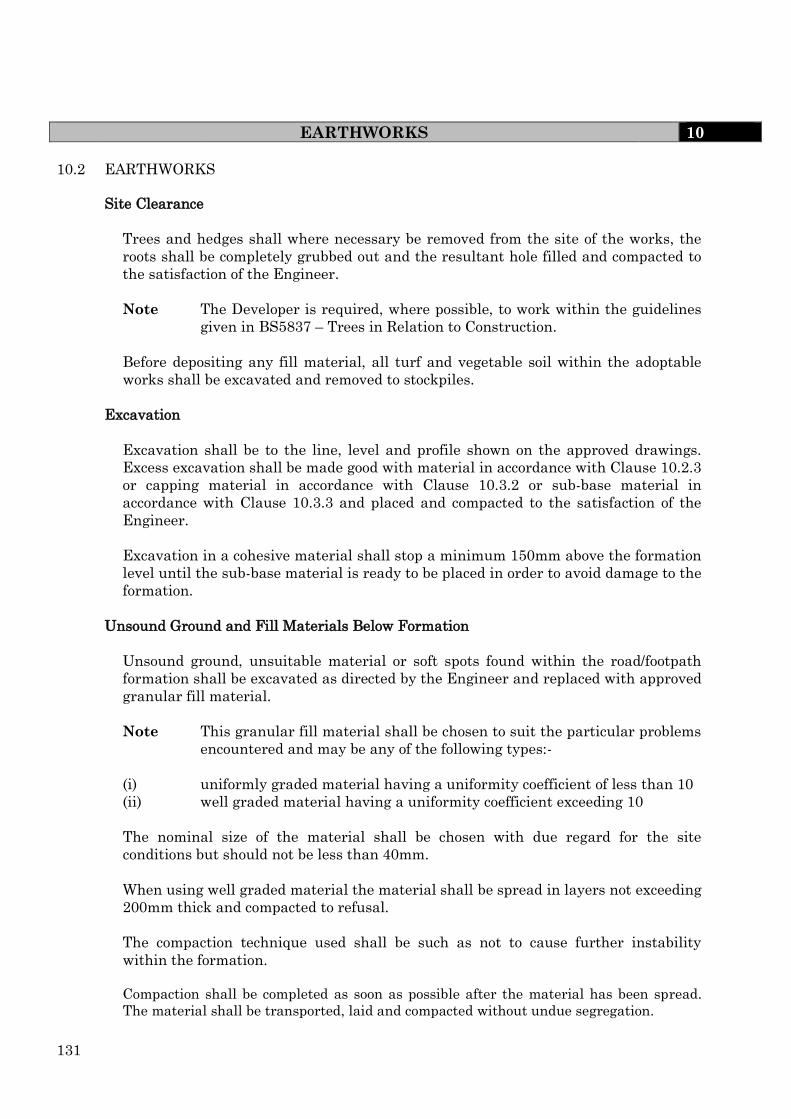
131
EARTHWORKS 10
10.2 EARTHWORKS
Site Clearance
Trees and hedges shall where necessary be removed from the site of the works, the
roots shall be completely grubbed out and the resultant hole filled and compacted to
the satisfaction of the Engineer.
Note The Developer is required, where possible, to work within the guidelines
given in BS5837 – Trees in Relation to Construction.
Before depositing any fill material, all turf and vegetable soil within the adoptable
works shall be excavated and removed to stockpiles.
Excavation
Excavation shall be to the line, level and profile shown on the approved drawings.
Excess excavation shall be made good with material in accordance with Clause 10.2.3
or capping material in accordance with Clause 10.3.2 or sub-base material in
accordance with Clause 10.3.3 and placed and compacted to the satisfaction of the
Engineer.
Excavation in a cohesive material shall stop a minimum 150mm above the formation
level until the sub-base material is ready to be placed in order to avoid damage to the
formation.
Unsound Ground and Fill Materials Below Formation
Unsound ground, unsuitable material or soft spots found within the road/footpath
formation shall be excavated as directed by the Engineer and replaced with approved
granular fill material.
Note This granular fill material shall be chosen to suit the particular problems
encountered and may be any of the following types:-
(i) uniformly graded material having a uniformity coefficient of less than 10
(ii) well graded material having a uniformity coefficient exceeding 10
The nominal size of the material shall be chosen with due regard for the site
conditions but should not be less than 40mm.
When using well graded material the material shall be spread in layers not exceeding
200mm thick and compacted to refusal.
The compaction technique used shall be such as not to cause further instability
within the formation.
Compaction shall be completed as soon as possible after the material has been spread.
The material shall be transported, laid and compacted without undue segregation.

132
EARTHWORKS 10
Any subsequent construction settlement due to the failure of the sub-grade will
remain the Developer's responsibility.
General Fill Material
(i) Embankments
Embankments shall be constructed with acceptable earthworks materials in
accordance with the Department of Transport Specification for Highway Works
(SHW) – Series 600 – Earthworks.
All fill materials shall require the approval of the Engineer.
Note Class 1B uniformly graded granular material in accordance with table 6/1
of the SHW has shown in the past not to perform well as embankment fill
and therefore will not be permitted.
(ii) Site Investigation
The Developer shall inform the Engineer in writing that the Site Investigation
reports contain information that indicates that the area of interest is
contaminated. The reference in the Site Investigation reports to the type,
distribution and concentration of the contaminants together with an assessment
of their impact on the intended works and proposed method of remediation shall
be reported to the Engineer.
Advice on the design and execution of a site/ground investigation should be
obtained from a specialist consultant. Attention is drawn to the following
documents:-
NHBC Standards, Chapter 4.1, Land Quality – Managing Grand Conditions.
BS5930 Code of Practice of site investigations.
Remedial Action – Where a site/ground investigation has shown that
contaminates are present over the whole or part of the site in concentrations
that indicate that remedial action may be necessary, the Developer must provide
the Engineer with the following information:-
(a) the nature and concentrations of contaminates
(b) the hazards associated with those contaminates
(c) the intended remedial action
Note The remedial action will normally be one or a combination of the
following methods, all of which would require the Engineer's approval.

133
EARTHWORKS 10
(1) Contaminated material is excavated and removed for disposal off site and
replaced (if necessary) by uncontaminated imported fill.
(2) The contaminated material is isolated beneath, (and where necessary
laterally) by a suitable thickness of imported, clean cover material at the
interface with the contaminated material.
(3) The material is chemically or physically treated without removal to
reduce the contamination.
Breaklayer – Where the remedial action involves the covering of contaminated
material with a breaklayer then the breaklayer shall be as follows:-
The Developer must provide a minimum breaklayer of 1000mm thickness. The
aggregate used for the breaklayer shall be unbound, inert and non-water
susceptible graded to the requirements of SWH, Series 600 Table 6/2 Class 6F1
or 6F2.
The breaklayer shall be placed and compacted in accordance with the method
compaction requirements of Clause 612 and method 6 of Table 6/4 given in SHW
600 series.
The breaklayer thickness may be reduced to a minimum thickness of 600mm
subject to approval by the Engineer on the material source, material type and
grading and the use of end product compaction requirements as given by Clause
612 of the SHW. Examples of permitted material types for a reduction to 600mm
are whinstone, carboniferous limestone, magnesium limestone, blast furnace or
steel slag from an approved source.
The use of permanent hard surface cover as a breaklayer will be considered
depending upon the nature of the contaminates and the concentrations of such
contaminates.
The Developer shall provide to the Engineer all relevant materials testing
information after construction of the breaklayer indicating that all aspects of the
above specification have been achieved and this shall include the following as a
minimum:-
(a) aggregate source and type
(b) grading
(c) compaction achieved (where applicable)
Where the use of a breaklayer has been approved, then information is required
by the Engineer to assess compliance with the Specification in respect of the
permanent hard surface cover.
Embankments above a breaklayer must be constructed with imported material
from a source approved by the Engineer. The use of in-situ reclaimed material
will not be permitted.

134
EARTHWORKS 10
(iii) Fill to structures
Fill to structures shall be in accordance with the requirements of the
Specification for Highway Works (SHW) – Series 600 – clause 610 with the
exception that the material shall be normally be restricted to Class 6N (selected
well graded granular material) or 7B (selected conditions pulverised fuel ash).
Where the Developer wishes to use other fill material approval must be given by
the Engineer and the fill must comply with the requirements of clause 610 and
table 6/1 of the SHW.
Standing Water
The Developer shall arrange for the rapid dispersal of water shed onto or entering
the works from any source at any time during construction. Where necessary
temporary ditches, watercourses, pumping or other means of maintaining the works
free from standing water shall be used. The water shall be discharged only to
locations approved by the Engineer.
Care must be taken to prevent solid matter or matter in suspension from entering
any drains or sewers. Any obstruction shall be removed by the Developer.
Road and Footpath Formation
The Engineer will require a minimum 24 hours notification from the Developer prior
to the commencement of the following works.
(i) The placing of capping or sub-base material on the formation.
(ii) The placing of any kerbs or channels on the kerb raft.
(iii) The laying of any bituminous material.
All trenches in the sub-grade shall be backfilled in accordance with Clause 12.4.4 to
the satisfaction of the Engineer prior to the final preparation of the formation which
shall be carried out as follows:-
(i) All formations shall, after reinstatement of any soft areas, shall be clean and free
from mud and slurry. Soft and unstable areas within the formation are often
highlighted by rolling and/or construction traffic.
(ii) The carriageway formation shall be compacted by at least four passes of a
'smooth wheeled' dead weight roller having a load of 6-12 tonne to the
satisfaction of the Engineer.
(iii) During completion of the footpath formation, due regard shall be made to service
installations and be compacted by at least 4 passes within a 2.5 tonne dead
weight roller to the satisfaction of the Engineer.

135
EARTHWORKS 10
(iv) The formation shall be regulated and trimmed (by hand if necessary) to the
correct levels and profiles. Trimmed formations shall be rolled as in (ii) or (iii) as
appropriate.
On completion, the formation (unless directed otherwise by the Engineer) shall
be sprayed, with an approved weedkiller. This operation shall be completed
before overlaying the formation with capping (where required) or sub-base.
When completed, the prepared formation shall be clean, free from mud and
slurry, shaped to the required level and be within the specified surface
tolerances (see Clause 10.3.1).
Construction traffic shall not be allowed to run on the prepared formation
without the Engineer's approval. Any damage caused to the formation (by any
means) shall be rectified to the satisfaction of the Engineer prior to the placing of
capping (where required) or sub-base material.
The Developer must arrange the work so that the earthworks, formation
preparation, capping layer (where required) and sub-base laying proceeds as
a continuous operation.
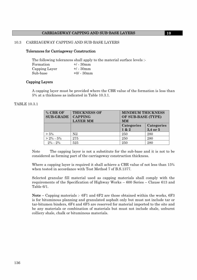
136
CARRIAGEWAY CAPPING AND SUB-BASE LAYERS 10
10.3 CARRIAGEWAY CAPPING AND SUB-BASE LAYERS
Tolerances for Carriageway Construction
The following tolerances shall apply to the material surface levels :-
Formation +/ - 30mm
Capping Layer +/ - 30mm
Sub-base +0/ - 30mm
Capping Layers
A capping layer must be provided where the CBR value of the formation is less than
5% at a thickness as indicated in Table 10.3.1.
TABLE 10.3.1
% CBR OF
SUB-GRADE
THICKNESS OF
CAPPING
LAYER MM
MINIMUM THICKNESS
OF SUB-BASE (TYPE)
MM
Categories
1 & 2
Categories
3,4 or 5
> 5% Nil 250 280
> 2% - 5% 275 250 280
2% - 2% 525 250 280
Note The capping layer is not a substitute for the sub-base and it is not to be
considered as forming part of the carriageway construction thickness.
Where a capping layer is required it shall achieve a CBR value of not less than 15%
when tested in accordance with Test Method 7 of B.S.1377.
Selected granular fill material used as capping materials shall comply with the
requirements of the Specification of Highway Works – 600 Series – Clause 613 and
Table 6/1.
Note – Capping materials :- 6F1 and 6F2 are those obtained within the works, 6F3
is for bituminous planning and granulated asphalt only but must not include tar or
tar-bitumen binders, 6F4 and 6F5 are reserved for material imported to the site and
be any materials or combination of materials but must not include shale, unburnt
colliery shale, chalk or bituminous materials.
137
CARRIAGEWAY CAPPING AND SUB-BASE LAYERS 10
Capping layers shall be compacted in accordance with Clause 10.3.4 and Table
10.3.3.
Aggregates for capping shall be from a source approved by the Engineer. They shall
be free from detritus such as slag (from any source other than that approved by the
Engineer), clay, plaster, wood, domestic waste, industrial refuse and any other
material which in the opinion of the Engineer would adversely effect the durability
of the highway.
Sub-Base Material
The sub-base material shall comply with the requirements of the Specification of
Highway Works – 800 Series – Type 1. Acceptable materials shall be crushed rock
(excluding shale), crushed blast furnace slag, crushed concrete, secondary and
recycled aggregates. The material must not be frost susceptible when tested in
accordance with SHW Clause 600.
All sources of aggregate require the Engineers approval.
Notes
(a) Slag material shall comply with the requirements of BS EN 12620
Appendix A with the exception that the analytical test for dicalcium
silicate unsoundness shall satisfy both conditions of sub-clause E3.1 of
that British Standard. The bulk density of slag shall not be less than
1100 kg/m3. Steel Slag or mixtures of steel and blast furnace slag are not
permitted.
(b) The aggregate used for sub-base material shall be from a source approved
by the Engineer. Where a source is proposed by the Developer which is
unknown to the Engineer, then all of the requirements of the
Specification for Highway Works Series 800 shall apply and approval will
only be given when full compliance with these requirements is shown.
(c) The sub-base material shall have a Los Angeles fragmentation value of
less than LA50 when tested in accordance with BS EN 1097.
Compaction
The material shall be placed, spread in layers not exceeding 150mm thick and
compacted to the satisfaction of the Engineer.
Table 10.3.3 gives a guide to compaction requirements but the Engineer may require
further compaction to be carried out.

138
CARRIAGEWAY CAPPING AND SUB-BASE LAYERS 10
TABLE 10.3.3
TYPE OF
COMPACTION
PLANT
CATEGORY NUMBER OF PASSES FOR
Not Greater
than 110 mm
Not Greater
than 150 mm
Smooth
wheeled
Roller
Mass per metre
width of Roller
2.5 – 5.5 tonne
over 5.5. tonne
16
8
Not suitable
16
Notes
(a) The use of vibrating rollers will not be permitted.
(b) All loose, or segregated, areas shall be made good to the full
thickness of the layer and re-compacted. Where clay or other sub-
grade material has worked through the sub-base the area shall be
dug out together with any defective formation and replaced with
new material and compacted as described in Clauses 10.2.3 and
10.2.6.
(c) The road base should be laid as soon as possible after the sub-base
has been prepared. If by using the sub-base as a “working
platform” contamination, damage or deterioration to the formation
and/or sub-base occurs, then this shall be rectified to the
satisfaction of the Engineer before the road base material is laid.
Where a final trim to the sub-base is required, then the base (road
base) shall not be laid until this final trim has been inspected by
the Engineer.
Only those vehicles and equipment necessary for the laying of the
base (road base) material shall be allowed to traffic the area
during the laying operations.
The sub-base thickness may have to be increased to ensure a
minimum carriageway thickness of 450mm (clause 10.7.2).
Frozen Materials
Frozen material shall not be used but may be retained on site for use when free from
frost and ice, subject to the approval of the Engineer. No material shall be laid on any
surface that is frozen or covered with ice.

139
KERBS, CHANNELS AND EDGINGS 10
10.4 KERBS, CHANNELS AND EDGINGS
Pre-Cast Concrete Products
Precast concrete kerbs, channels and edgings shall comply with the requirements
given in B.S. 7263-3 and shall be laid in accordance with the requirements of B.S.
7533 – Part 4 with the exceptions as given below (see clause 10.4.3 – Edgings).
The units shall have performance requirements as given below:
(a) Weathering resistance – all units shall be of class W2.
(b) Abrasion resistance – all units shall be class A2.
(c) Slip/skid resistance – all units for predominately pedestrian use shall be
of class S2. For channels and kerbs laid as channels in areas of vehicular use
shall be of class S3.
Note: Testing the above performance requirements shall be in accordance with
the relevant annex of B.S. 7263-3.
Natural Stone Kerbs
Natural stone kerbs shall only be used with the approval of the Engineer and shall
comply with B.S.435 and be igneous rock of a size 200mm x 150mm x 75mm.
Samples shall be submitted to and approved by the Engineer prior to their use and
the kerbs used shall be equivalent or superior to the approved sample.
Edgings
Flat top edgings shall be laid as follows:
They are to finish flush with the footpath level and laid with butt joints bedded on
15mm thick 3:1 cement mortar (see sketch 10.4.6) or laid directly onto the concrete
foundation (see sketch 10.4.1).
Foundations
The foundations shall be constructed using S2 concrete complying with the
requirements of BS EN 206 and shall be constructed with formwork set to the
required line and level. The concrete shall be well compacted to provide a dense
homogeneous mass.
Kerb foundations shall have hooped mild steel bars 10mm diameter by 350mm long
at 600mm centres which are to be set into the foundation as the concreting proceeds
to provide a key for the concrete backing.
Foundation widths must not be wider than that required to carry the kerb, channel
(where required) and backing. (See Sketch 10.4.2).
For foundations to footpath, footway or footpath/cycletrack, the
requirements of Clause 10.1.1 (vi) in respect to soil classification
must be noted.

140
KERBS, CHANNELS AND EDGINGS 10
Installation
(i) Kerbs and Channels – Kerbs and channels (where required) shall be laid in
full lengths. Where “piecing up” is necessary, units must not be cut to less
than half length.
Note Should the Developer wish to omit the kerb until building works are
substantially complete, then the channels must be temporarily backed
with S2 concrete to the satisfaction of the Engineer.
After buildings works are substantially complete and the Developer wishes to
complete the kerbing works, the temporary concrete backing shall be
removed.
Kerbs and channels (where required) are to be laid with butt joints on a
mortar bed (see Clause 10.4.6) not less than 10mm or greater than 40mm
thickness to comply with the finished level and in the case of kerbs to
produce a 125mm or 100mm kerb face.
In shared surfaces a kerb face of 50mm may be acceptable, with the approval
of the Engineer and in these situations only small element units complying
with B.S. 7263 shall be used.
For channels less than 6m radii, straights shall be used having a minimum
length of 300mm. Gaps formed by this construction method shall be filled
and sealed using a material to be approved by the Engineer.
Damaged kerbs and/or channels will be inspected by the Engineer and those
considered as having minor damage, may be repaired using a concrete repair
system approved by the Engineer. Other damaged kerbs and/or channels
shall be removed, replaced and the foundation cleaned prior to the kerbs
and/or channel being re-laid.
Kerbs and/or channels shall be laid to the design level +/-6mm. Any kerb
and/or channel found to be more than 3mm out of line and level over a 3m
length shall be lifted and re-laid.
Kerbs shall not be backed until installation works have been approved by the
Engineer.
(ii) Edgings – Edgings shall finish flush with the footpath level and shall be laid
with butt joints. They shall be bedded on a mortar bed of thickness not less
than 10mm and not greater than 20mm. Where required for piecing up they
must not be less than 300mm in length.
Mortar Bedding
Mortar bedding layers shall consist of freshly mixed moist mortar of 3 : 1 sand :
cement (proportions by volume) using a sand complying with BS EN 13139, 0/4 MP.
Cement mortars, which have been mixed and not used for more than 2 hours shall
be discarded.

141
KERBS, CHANNELS AND EDGINGS 10
Sketch No 10.4.1 TYPICAL FOOTPATH/CYCLETRACK EDGE DETAIL
10
0m
m
Overa
ll de
pth
up to 6
00m
m *
150mm
50mm
125mm
15
0m
m
varies
To suit construction works
275mm min width
13mm
20
mm
50 x 150mm P C
Concrete edging kerb
Grade S2 Concrete
backing & foundation
Finished footpath surface level
Dense surface course
Dense binder course
3 : 1 sand/cement bed
Sub Base
This face must
be shuttered
40
mm
varies
Overa
ll de
pth
up to 6
00m
m *
50 x 150mm P C
Concrete edging kerb
13
0m
m
Sub Base
This face must
be shuttered
15
0m
m
To suit construction works
275mm min width
13mm
125mm
50mmFinished footpath surface level
90
mm
3 : 1 sand/cement bed
Grade S2 Concrete
backing & foundation
10
0m
m
150mm
63
mm
25
mm
max
Precast concrete flags
Sharp sand
75mm
BITMAC FOOTPATH / CYCLETRACK
40
mm
13
0m
m
50
mm
90
mm
75mm
FLAGGED FOOTPATH
* Note Actual thickness dependant upon soil classification

142
KERBS, CHANNELS AND EDGINGS 10
Sketch No 10.4.2 TYPICAL KERB DETAIL

143
DUCTS 10
10.5 DUCTS
Cross Road Ducts
Ducts for mains and service crossings under roads are to be laid in accordance with
the requirements of the Statutory Undertakers at an approximate depth of 750mm
below the surface of the carriageway. They shall generally be 100mm diameter and
extend into the footpath or verge 300mm behind the kerb foundation.
All telecommunications ducts shall be set a minimum of 1.5m from any others.
The ducts are to be surrounded for their entire length in 150mm sharp sand with a
S2 grade concrete cover slab. The ends of the pipe sealed to prevent ingress of any
material. A draw cord shall be provided through the duct.
Duct Markers
A marker is to be placed in the kerb backing above the duct position and flush with
the top of the kerb on both sides of the road. If the kerb is not to be provided until a
later stage of the works the duct marker shall be temporarily placed behind the
channel and on laying the kerb the duct marker shall be relocated behind the kerb.
Duct markers shall be pre-cast concrete posts 60mm square by 125mm or 275mm
long. The top face shall be finished smoothly with the letter of the service recessed
therein as shown below.
E – Electricity
G – Gas
W – Water
T – Telecom
SL – Street Lighting
C – Other
Sketches
Typical detail are shown on Sketch 10.5.1
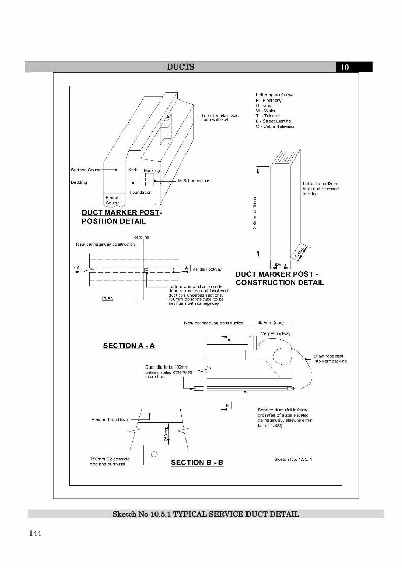
144
DUCTS 10
Sketch No 10.5.1 TYPICAL SERVICE DUCT DETAIL

145
CONCRETE 10
10.6 CONCRETE
Mixes and Quality
Concrete mixes may be Designed, Designated, Prescribed, Standardized or Proprietary
and shall conform to the requirements of BS EN 206-1 and BS 8500-1.
Concrete design mixes must be submitted to the Engineer for approval.
Note Concrete Exposure classes
The Developer is required to determine the exposure
classes of all concrete. Exposure classes for concrete shall
be selected from tables A.1 and A.2 of BS 8500-1. Where
chemical attack of buried concrete needs to be considered
then the aggressive chemical environment for concrete
(ACEC-class) shall be selected from table A2 of BS 8500-1
and converted to a design chemical class (DC-class) and,
where appropriate the number of additional protective
measures (APM’s) using table A.3 and A.4 of BS 8500-1.
Structural Concrete
Concrete which is to be used for structural work (bridges, headwalls, etc) shall comply
with the requirements of the Specification for Highway Works 1700 – Series or with the
Water Association Sewers for Adoption specification.
Testing of fresh and hardened concrete for structural work shall be in accordance with
clause 1707 – Concrete Conformity of the Specification of Highway Works.
The Engineer may at any time increase the testing rates of both fresh and hardened
concrete to ensure the finished structure is of an acceptable standard for adoption. The
Engineer may use the results obtained from such testing to accept or reject the fresh or
hardened concrete.
Concrete Grades
Table 10.6.1 gives examples of concrete grades.

146
CONCRETE 10
TABLE 10.6.1
DESIGNATED MIXES STANDARD
PRESCRIBED
MIXES
CHARACTERISTIC
COPRESSIVE CUBE
STRENGTH (N/mm2)
GEN 0
ST1
8
GEN1 ST2 10
GEN2 ST3 15
GEN3 ST4 20
FND (all designations)
35
PAV1
30
PAV2 35
RC25
RC30
RC35
RC40
RC45
RC20
RC 50XF
25
35
35
40
45
50
50

147
CONCRETE 10
TABLE 10.6.2
APPLICATION DESIGNATE
D
CONCRETE
STANDARDISED
PRESCRIBED
CONCRETE
RECOMMENDED
CONSISTENCE
CLASS
Foundations requiring
DC-1 concrete
GEN 1
ST2
S3
Blinding & Mass GEN 1 ST2 S3
Concrete fill GEN 1 ST2 S3
Strip footings
Mass concrete foundation
Trench fill foundations
Fully buried reinforced
foundations
GEN 1
RC30
ST2
Not any
S3
General applications
Kerb bedding and backing
Drainage works to give
immediate support
Other drainage works
GEN 0
GEN 1
GEN 1
GEN2
ST1
ST2
ST2
ST2
S1
S1
S1
S3
Paving
House drives
Domestic parking
External parking
Heavy duty external
paving with rubber tyre
vehicles
PAV1
PAV1
PAV1
PAV2
-
-
-
-
S2
S2
S2
S2
Table 10.6.2 gives guidance of the selection of designated and standardised prescribed
concrete in various applications (for the full guidance see BS 8500 – Table A.7)
Constituent Materials of Concrete
(i) Cement
Cement shall comply with the requirements given in Table A.17 of BS 8500 – 1.
The use of rapid hardening cement to allow early trafficking of the concrete
requires the approval of the Engineer.
(ii) Aggregates
Aggregates shall conform with the list given in clause 4.3 of BS 8500 except that
recycled concrete aggregates and recycled aggregates are not permitted within
concrete mixes intended for structural use
148
CONCRETE 10
(iii) Water
Only water from a water company supply shall be used.
(iv) Admixtures
No admixture other than an air-entrained admixture, where specified, complying
with BS EN 934.2 shall be incorporated in the concrete without specific written
agreement of the Engineer.
Plasticisers or water reducing admixtures, where permitted by the Engineer,
shall comply with BS EN 934.
Admixtures containing calcium chloride shall not be used.
(v) Chloride content
The limits of chloride content of the concrete shall be as given in clause 5.2.7 and
table 10 of BS EN 206.
(vi) Control of Alkali – Silica Reaction
The Developer shall ensure that the concrete producer takes action to minimize
the damaging effect of alkali-silica-reaction by applying one of the sets of
conditions given in 5.2 of BS 8500-2.
Properties of Fresh Concrete
(i) Consistency
For normal concrete mixes the consistency of the concrete will be low to medium
corresponding to a target slump value of 50mm to 75mm respectively.
Where a high consistency concrete is required (e.g. concrete section containing
congested steel) then the target slump can be as high as 125mm with the
approval of the Engineer.
Note(a) Consistency classes and target values are given in BS EN 206-1 clause
4.2 Table 3 and clause 5.4 Table 1 respectfully.
Note(b) The consistency of designed mixes for structural use shall be selected
by the Developer with regard to the method of placement, congestion
of steel within the framework, surface finish specified and method of
compaction employed.
The consistency selected for each different mix shall be approved by the Engineer
before concrete placement operations commence.
(ii) Consistency at delivery
The addition of water or admixtures is not permitted to the mix during transit or
on site.
149
CONCRETE 10
(iii) Air Content
Limiting values for the composition and properties to resist freezing and thawing
(XF exposure) are given in BS 8500-1 table A.14. The values given in table A.14
are minimum values for entrained air related to exposure class and aggregate
size.
The minimum air entrained content manufactured with 20mm aggregate size is
3.5% with a maximum air content of 7.5%.
Ready Mixed Concrete
(i) Manufacture
Concrete shall be batched and mixed in accordance with BS EN 8500.
The Developer shall afford all reasonable opportunity and facility to the Engineer
to inspect the constituent materials and the manufacture of the concrete and if
required to take samples.
(ii) Changes in materials and/or mix composition
The Developer shall inform the Engineer of any proposed changes in the source of
nature of any of the mix constituents and any changes in mix composition which
can affect the requirements of the hardened concrete.
Any such changes shall not take the cement content, water: cement ratio or
chloride content outside the specified limits or increase the risk of ASR.
(iii) Transport and Delivery
Concrete shall be transported in purpose-made truck mixers except in special
circumstances, where the Engineer may permit delivery by other types of delivery
vehicle.
All such special circumstances shall be agreed with the Engineer before concrete
delivery commences.
Formwork
The Developer shall provide all necessary formwork, which shall be thoroughly cleaned
and coated with an approved material to prevent adhesion of fresh concrete and set so as
to ensure that there is no loss of material.
Formwork shall only be struck when the concrete has attained adequate strength and
with the approval of the Engineer.
Note Adequate strength shall be determined by site curing at least one test cube in
the same environmental conditions as the concrete. The compressive
strength of the cube shall not be less than 40% of the characteristic
compressive strength before the formwork is removed.

150
CONCRETE 10 Placement
The concrete must be placed and compacted within two hours of the introduction of water
to the cement/aggregate.
Concrete shall not be dropped into place from a height exceeding 1.3m. It shall be placed
so that there is no contamination, segregation, or loss of the constituent material or
displacement of any reinforcement. Compaction is to be complete within 30 minutes of
discharge from the mixer.
Fresh concrete shall not be placed against concrete which has been in position for more
than 30 minutes, without the approval of the Engineer. When concrete has been placed
for more than 2 hours, no further concrete shall be placed against it for another 24 hours.
The Developer must submit proposals to the Engineer for approval before any further
concrete pour takes place.
Concrete must not be placed in flowing water.
Cold Weather Working
Concreting at ambient temperature below 2oC may only be carried out with the
agreement of the Engineer and if the following conditions are met:-
(i) the aggregates and water used in the mix are free from snow, ice and frost
(ii) any formwork, reinforcement and surface with which the concrete will be in
contact are to be free from snow, ice and frost and be at a temperature above 0oC.
(iii) the temperature of the concrete at the time of placing shall not be less than 5oC.
(iv) the temperature at the surface of the concrete must be maintained at not less
than 5C measured at any location until the concrete strength reaches a strength
of 5 N/mm2 as confirmed by test cubes cured under similar conditions.
(v) where required thermal insulation blankets are employed immediately after
placing and finishing the concrete and shall be retained in place for a minimum of
3 days or until the concrete has reached 50% of the specified characteristic
compressive strength.
Compaction
All concrete shall be compacted to produce a dense homogeneous mass.
Unless otherwise agreed by the Engineer it shall be compacted by using vibrators and a
sufficient number should always be on site as replacements in case of breakdown.
Where immersion type vibrators are used, contact with reinforcement and all inserts is to
be avoided. Care must be taken not to over vibrate the concrete and cause segregation,
or damage to work that has set. This compaction must be completed within 2 hours of
the addition of water.
Concrete must not be further vibrated after compaction.

151
CONCRETE 10
Sampling and Testing
All sampling, curing of cubes and testing of concrete, fresh and hardened, shall be carried
out in accordance with the requirements of the specifications BS 12350 and BS 12390.
Note (a) Sampling shall take place at the point of delivery into the construction unless
otherwise agreed by the Engineer.
Defects in Concrete
Any defects which in the opinion of the Engineer may be detrimental to the safety and/or
durability of the concrete construction, may be rejected even if satisfactory test results
have been obtained.
Minor surface defects may be made good subject to the Engineer’s approval. Any
remedial works carried out with the Engineers approval may be liable to rejection as
defective work.
Reinforcement for Lay-bys
The reinforcement may be steel mesh or fibre reinforcement.
Steel mesh reinforcement shall comply with the requirements of BS 4483 and shall be
free from oil, dirt, rust and scale. The reinforcement shall be placed with 60mm+/10mm
cover from the finished surface.
The reinforcement shall terminate 125mm+/-25mm from the slab edges and terminate
300mm+/-50mm from the transverse joint.
Where fibre reinforcement is to be used then the Developer shall inform the Engineer of
the type, size and dosage rate.
For typical details see Sketches 10.6.1 and 10.6.2.
Air-Entrained Concrete
Air-entrained concrete shall satisfy all of the specification requirements for the
pavement grades (PAV1 & PAV2) in Table 10.6.1.
Unless otherwise permitted by the Engineer, the fine aggregate used in the production of
air-entrained concrete shall be uncrushed natural sand complying with the requirements
of BS EN 12620.
The air-entrainment agent shall be added at the batching plant and its volume noted on
the delivery ticket.
Curing of Concrete
Immediately on completion of the placing and compaction, the concrete shall be cured i.e.
protected against the harmful effects of weather, including rain, rapid temperature
changes, and frost and from drying out. The method of curing shall provide a suitable
environment for the concrete to mature and prevent harmful loss of moisture.

152
CONCRETE 10
The concrete shall be cured for a minimum period of 7 days unless otherwise agreed by
the Engineer.
The use of all curing liquids, compounds, membranes and methods used shall be
submitted to the Engineer in writing for approval and shall not be employed until
approval is given.
During the curing period the concrete shall be protected from use by traffic or any other
form of loading which may adversely affect its future performance.
Joint filler and Sealant
For concrete lay-bys the joint fillers shall be pre-formed and of an approved quality.
Joint sealants shall be either hot or cold poured, or pre-formed. Whichever method is
used it must be approved by the Engineer.
If poured sealants are used any spillage or surplus must be removed to the satisfaction of
the Engineer.

153
CONCRETE 10
Running surface
Mesh Reinforcement
Concrete slabs (Air-entrained)
Sub-base
Formation level
Sub-grade
Expansion joint Contraction joints
400mm
6mm dia
5mm dia
100mm
Refer to clause 10. 6. 3
200mm
150mm
B S Ref C283
Longitudinal lap Correct Wrong
<450mm Transverse lap
TERMINOLOGY SECTION
MESH JOINTS (PLAN)
LAPS IN MESH
>16.5m
Sketch No 10.6.1 TYPICAL REINFORCED CONCRETE LAY-BY DETAIL

154
CONCRETE 10
Sketch No 10.6.2 TYPICAL REINFORCED CONCRETE LAY-BY JOINTING DETAILS
Sketch No 10. 6. 2
30mm
25mmMesh 60mm
25mm
flexcell orsimilar
Joint sealingcompound
30mm
Mesh 60mm25mm
10 mm
Mesh 60mm25mm
10mm
25mm
25mm
Compressible material
e. g. cottonwool
Cardboard tube
This length dowel
painted with bitumen
Induced crack
Timber fillet
Note Mesh is continuous in
construction joint
EXPANSION
JOINT
CONTRACTION
JOINT
EXPANSION JOINT
WITH DOWEL
LONGITUDINAL JOINT
(TIES BARS TO BE USED)
CONSTRUCTION
JOINT

155
BITUMINOUS MATERIALS 10 10.7 BITUMINOUS MATERIALS
Quality Assurance Scheme for the Production of Bituminous Materials and Laying of
Bituminous Materials.
All contractors used in the supply and laying of bituminous materials for roads and
footways shall be accredited under the following UKAS sector schemes
Sector Scheme 14 - For the quality assurance of the production of asphalt
mixes
National Highways Sector Schemes for Quality Management in Highway
Works 16 for the laying of asphalt mixes
Details of these schemes can be found on the UKAS web site http://www.ukas.com
The developer must, prior to the commencement of surfacing activities, submit for
approval, the proposed contractor along with a copy of the Certificate of
Accreditation under the UKAS Sector 16 scheme.
The details of any supplier of materials must also be submitted at the same time,
together with a copy of the suppliers Certificate of Accreditation under the UKAS
Sector 14 scheme.
Contractors who are not accredited by either of the above schemes must gain the
permission of the Engineer prior to commencement of any bituminous surfacing
works. Any contractor, who is not Accredited under the UKAS sector schemes, must
submit as part of the request for a deviation, a quality plan which will assure the
competence of the laying operation and the quality of the materials to be used.
The term asphalt is the generic term now employed throughout the E.C. for all mixtures
of mineral aggregate, including filler, and a bituminous binder. For simplicity however
and to match our existing specification the term bituminous materials have been
retained.
Only those bituminous materials manufactured by plants which hold accreditation from
and comply with the requirements of THE NATIONAL THIRD – PARTY QUALITY
ASSURANCE SCHEME FOR THE PRODUCTION OF BITUMINOUS MATERIALS
(the SCHEME) shall be used in the permanent works.
(The SCHEME has been jointly developed by the County Surveyors Society, Highways
Agency and BACMI)
Before the supply of any bituminous materials the Developer shall submit to the
Engineer documented evidence that all primary and secondary support plant/s proposed
by the Contractor from which supplies are to be delivered have been assessed under the
terms of Part 1 of the Scheme and that the plants operate at a Quality Level of Q6 or
better.
Where a plant is classified as having a Quality Level of Qx, assessed in accordance with
the criteria given in clause 6.2 (iv) of the Scheme, then material from the plant will not
be acceptable within the permanent works without the permission of the Engineer.

156
BITUMINOUS MATERIALS 10 Note: - A plant shall be classified as having a Quality Level of Qx only
when the 14 day action period fails to re-establish a Q level of Q6 or
better. During the 14 day action period the plant shall be deemed to
have an acceptable Q level for delivery.
The Developer shall appraise the Engineer of any change in the quality status of any
plant at the earliest opportunity.
Where the supply of bituminous materials is for a period of more than 7 continuous
supply days then the Developer shall submit to the Engineer the weekly OCL level for
each plant/s used over the full supply period.
After any interrupted supply of more than 7 supply days then the Developer shall
submit to the Engineer the plant/s OCL level before supply re-commences.
The Engineer may at any time during the supply perform audit checks on the material
as delivered to site. These audit checks will be at any frequency as decided by the
Engineer and may be any combination of the following: -
Suitability of delivery vehicles
Organoleptic checks of material in the body of the vehicle and on discharge into
the paver or stockpile
Temperature
Compositional analysis
Hot sand test for coated chippings
Where any of the Engineers audit checks indicate non-compliance to specification then
the Engineer shall be afforded the right to audit the plant and all documentation /
results as are required to be obtained for that supply under the Scheme.
The Engineers audit checks, with the agreement of all parties, may be used, in
combination with the plant results, to calculate the OCL level of the supply plant.
The Developer shall ensure that as part of the Producers quality plan where plant
inspection and testing of the finished material as performed by the Producer shows non-
conformity then the Developer is informed without delay.
It shall be the responsibility of the Developer to ensure that the Engineer is appraised of
this information at the earliest opportunity.
Failure to inform the Engineer will risk having the material removed and plant
approval withdrawn until the cause of the communication breakdown has been
identified and rectified to the satisfaction of the Engineer.
General compliance with the SCHEME does not prejudice the right of the Engineer to
reject any material found to be unsuitable for the works or falling into Category C as
described by the SCHEME.
Note 1 For shared surfaces and cycletracks which require a “red” bituminous
wearing course see Clause 10.7.7.

157
BITUMINOUS MATERIALS 10
Note 2 The use of slag based materials must be in accordance with Clause 10.1.5
TABLE 10.7.1
ASPHALTIC CONCRETE
MIXES
BS EN 13108-1
NOMINAL
AGGREGATE
SIZE
mm
NORMAL
LAYER
THICKNESS
mm
Heavy Duty Base
Dense Base
32
32
70 – 120
70 – 120
Heavy Duty Binder Course
Dense Binder Course
20
20
50 – 80
50 – 80
Close Graded Surface Course
Dense Surface Course
Fine (Sealing Grit)
14
10
6
3
40 – 55
30 – 35
20 – 30
15 – 25
TABLE 10.7.2
ASPHALT MIXES % STONE
CONTENT
AND
NOMINAL
SIZE mm
NOMINAL
LAYER
THICKNESS
mm
Base
Binder Course
Regulating Mixtures
60/32
60/20
50/20
50/14
50/10
70 – 150
45 – 80
45 – 80
35 – 50
20 – 35
Surface Course
30/14F
40
Rolled asphalt surface course mixtures shall be of the design mix type F and shall be
designed in accordance with the requirements given in B.S. 594987. The design
procedure shall be used to select a target binder content. The composition shall comply
with the requirements of PD6691:2007. All such designs will require the approval of the
Engineer.
Stability and flow requirements for rolled asphalt wearing course for the complete mix
at the target binder content shall be as follows:-
1. Stability – 4kN minimum to 10kn maximum. 2. Flow – 5mm maximum
The above design requirements shall be verified using materials obtained from the plant
and shall be carried out either by the supplier and witnessed by the Engineer or by a
laboratory approved by the Engineer by a UKAS Accredited Laboratory.
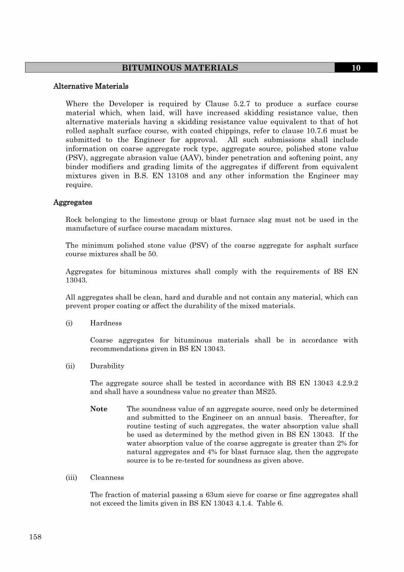
158
BITUMINOUS MATERIALS 10
Alternative Materials
Where the Developer is required by Clause 5.2.7 to produce a surface course
material which, when laid, will have increased skidding resistance value, then
alternative materials having a skidding resistance value equivalent to that of hot
rolled asphalt surface course, with coated chippings, refer to clause 10.7.6 must be
submitted to the Engineer for approval. All such submissions shall include
information on coarse aggregate rock type, aggregate source, polished stone value
(PSV), aggregate abrasion value (AAV), binder penetration and softening point, any
binder modifiers and grading limits of the aggregates if different from equivalent
mixtures given in B.S. EN 13108 and any other information the Engineer may
require.
Aggregates
Rock belonging to the limestone group or blast furnace slag must not be used in the
manufacture of surface course macadam mixtures.
The minimum polished stone value (PSV) of the coarse aggregate for asphalt surface
course mixtures shall be 50.
Aggregates for bituminous mixtures shall comply with the requirements of BS EN
13043.
All aggregates shall be clean, hard and durable and not contain any material, which can
prevent proper coating or affect the durability of the mixed materials.
(i) Hardness
Coarse aggregates for bituminous materials shall be in accordance with
recommendations given in BS EN 13043.
(ii) Durability
The aggregate source shall be tested in accordance with BS EN 13043 4.2.9.2
and shall have a soundness value no greater than MS25.
Note The soundness value of an aggregate source, need only be determined
and submitted to the Engineer on an annual basis. Thereafter, for
routine testing of such aggregates, the water absorption value shall
be used as determined by the method given in BS EN 13043. If the
water absorption value of the coarse aggregate is greater than 2% for
natural aggregates and 4% for blast furnace slag, then the aggregate
source is to be re-tested for soundness as given above.
(iii) Cleanness
The fraction of material passing a 63um sieve for coarse or fine aggregates shall
not exceed the limits given in BS EN 13043 4.1.4. Table 6.

159
BITUMINOUS MATERIALS 10
Bituminous Binders
The binder shall comply with those listed in Section 2, Clause 2.1 of B.S.EN 13108
Note The normal binder shall be penetration grade 40/60,
The binder grades shall be as given below:-
Machine laid materials
(a) Dense Asphaltic Concrete – 100/150 pen.
(b) Heavy Duty Asphaltic Concrete – 40/60 pen.
Penetration grade bitumen of 160/220 pen. may be used in machine laid with the
approval of the Engineer
Note - The use of 160/220 pen materials will result in increased layer thickness
and requires the Engineer’s approval.
No fluxing or volatile oils shall be permitted in the manufacture of machine laid
materials
Where Dense or Close Graded Surface Course materials are to be laid between the
1st June and the 1st October, the binder shall be 40/60 pen with a 3% addition of
Sasol Wax. This applies to both Footways and Highways. Alternatives will only be
permitted with the prior approval of the Engineer.
(b) Hand laid materials
Between the 1st June and 1st October, the binder shall be 40/60 pen with an addition
of 3% Sasol Wax.
Dense and Close Graded Asphaltic Concrete – 100/150 pen / 160/220 pen
Note - It is preferable to use penetration graded bitumen for all works, however
substantial advantages can be gained from using cut-back bitumen in
footpath locations which are hand laid and therefore binder viscosity of
200 secs may be permitted in these areas with the approval of the
Engineer.
Bituminous Sprays
A tack coat shall be applied to all surfaces more than 24 hours old or to any surface less
than 24 hours old which in the opinion of the Engineer requires treatment.
The tack coat shall be a bituminous emulsion complying with Class K1 – 40 of B.S. 434 :
Part 1 applied at a uniform rate of spread over the whole of the surfacing to be covered.
The emulsion shall not be allowed to collect in hollows and shall be allowed to “break”
before being overlaid.

160
If the Engineer requires proof that adhesion exists between layers then 150mm
diameter core samples shall be taken at locations indicated by the Engineer. Cold
Recycled Bitumen Bound Material (Foamix)
Foamix macadam is a specialist material which is produced from recycled, pulverised
and graded aggregates mixed with a foamed bitumen to give a macadam type mix for
use as a base (road base) and / or binder course. The bitumen, normally of 125 pen, is
foamed prior to mixing with the aggregate.
Foamix shall only be used as a base and / or binder course and requires approval of the
Engineer prior to installation. Approval will require a Quality Assurance Document
from the supplier incorporating the requirements given in BS EN 9001 and shall cover
the following:
a) Design Procedure
b) Control of Production
c) Component materials including any filler / adhesion agents used
d) Base bitumen
e) Process control including production testing
f) Control of non-conforming product
g) Advice on laying and compaction
h) In-situ testing control parameters.
The minimum acceptable design and characteristic requirements shall be given in the
Specification for Highway Works, Clause 948, Table 9/15. The compliance criteria for
process control shall be as given in the Specification for Highway Works, Clause 948,
Table 9/11.
The compaction achieved on site shall be measured using an approved gauge and shall
be continuous throughout the laying process. Information from the supplier on refusal
density to enable in-situ densities to be measured shall be supplied to the Engineer for
each day’s delivery.
Indirect tensile stiffness modulus (ITSM) shall be carried out on each day’s production
and the information shall be supplied to the Engineer. Testing shall be in accordance
with the requirements given in the Specification for Highway Works, Clause 948. Where
ITSM results indicates non-compliance then an investigation in accordance with the
Engineer’s requirements shall be performed by the supplier. Remedial action, if
required, shall be determined by the Engineer related to the findings of the
investigation.
Pre-Coated Chippings
Requirements for the supply, use and application of chippings shall be as stated in BS
EN 13108-4:2006 with the following additional requirements:-
When using hot rolled asphalt surface course the surface roughness shall be obtained by
using pre-coated chippings. The method of application of the coated chippings shall be
in accordance with the requirements of BS 594987.
BITUMINOUS MATERIALS 10

161
BITUMINOUS MATERIALS 10
The chippings shall be clean and free from any contamination which may prevent
permanent retention in the asphalt.
The maximum aggregate abrasion value of the chippings shall not exceed 12 and the
minimum polished stone value is to be 60 unless otherwise specified by the Engineer
Shared Surfaces and Cycleways
The surface course material is to be of a red colour. Coloured bituminous materials by
their nature are proprietary materials and are not covered by the materials specified in
BS EN 13108 and therefore the constituent materials requirements shall be devised by
the supplier to ensure a product that will give adequate durability. The one exception is
that the aggregate is to be red from a source approved by the Engineer.
The transporting, laying and compaction shall be generally in compliance with the
requirements of BS 594987. Where the supplier of these proprietary materials requires
other specialist operations then they shall be followed.
The Developer shall submit to the Engineer the proposed supplier and the following
minimum information of the proposed mix:-
(i) the composition of the mix with compliance specification limits for binder content
and grading.
(ii) binder penetration and any binder modification.
(iii) coarse aggregate source
(iv) fine aggregate source
Where the supplier wishes to change any of the constituent components of the approved
mix they must be submitted to the Engineer for approval.
All vertical joints must be treated with red bitumen or red bitumen emulsion.
Note:- It is recommended that those involved in the laying of red
pigmented bituminous materials seek advice on acceptable
laying practices from the supplier of such material before work
commences on site. This is to aid the safety of the cycleway.
Adjustment of Manholes Covers
The Developer shall be responsible for the adjustment of all manhole covers, hydrants,
service boxes and road gullies to suit the finished road level prior to the laying of the
surface course.
Any part of these covers against which surfacing material is to be laid shall be cleaned
and treated with hot bitumen or emulsion to the satisfaction of the Engineer.

162
BITUMINOUS MATERIALS 10
Tying into Existing Work
Where new work abuts onto or ties into an existing carriageway the surface of the
existing shall be scarified over a minimum length of 2m adjusted and re-shaped as
directed by the Engineer to comply with new camber and/or crossfalls. See Clause
10.7.13 for jointing requirements.
Surface Level Tolerances
The permitted deviation of the surface level of any pavement layer at any point from the
true surface level shall not exceed the following values:-
(a) sub-base to receive base road-base +0mm /-30mm
(b) base (roadbase) to receive binder course +/- 15mm
(c) binder course to receive surface course +/- 6mm
(d) binder course to receive surface course on areas other than roads e.g. car
parks, playgrounds +/- 10mm
(e) surface course + / - 6mm
The sum of the deviations in the levels of different pavements layers shall
not result in a reduction of the required design thickness by more than 8.5%
or in the overall surface course thickness by more than 5mm.
Transporting
Bituminous material shall be carried in clean insulated vehicles and shall be covered by
double sheets until tipped. The use of dust, coated dust or sand on the interior of the
vehicles to help in the discharge of the material is allowed but must be kept to a
minimum, with any excess removed prior to loading. Refer to Table 10.7.3 for maximum
delivery temperatures.
Bituminous materials shall, on delivery to site, be fully and uniformly coated.
All bituminous materials shall be manufactured, transported, laid and compacted
without segregation of the aggregates, separation of the binder and cracking / tearing of
the layer.
Where any or all of these conditions occur and in the opinion of the Engineer they could
adversely affect the performance of the construction then the material shall be removed
and replaced.

163
BITUMINOUS MATERIALS 10 TABLE 10.7.3 (Extract from BS594987)
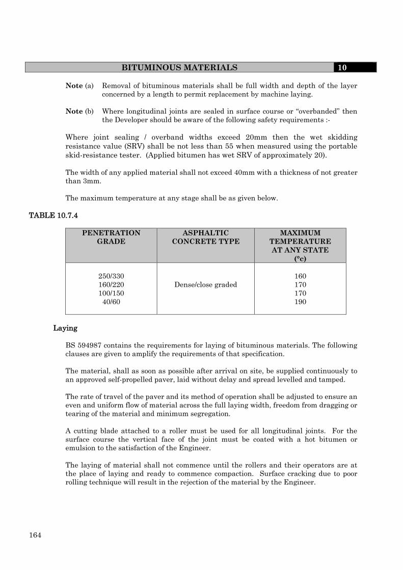
164
BITUMINOUS MATERIALS 10
Note (a) Removal of bituminous materials shall be full width and depth of the layer
concerned by a length to permit replacement by machine laying.
Note (b) Where longitudinal joints are sealed in surface course or “overbanded” then
the Developer should be aware of the following safety requirements :-
Where joint sealing / overband widths exceed 20mm then the wet skidding
resistance value (SRV) shall be not less than 55 when measured using the portable
skid-resistance tester. (Applied bitumen has wet SRV of approximately 20).
The width of any applied material shall not exceed 40mm with a thickness of not greater
than 3mm.
The maximum temperature at any stage shall be as given below.
TABLE 10.7.4
PENETRATION
GRADE
ASPHALTIC
CONCRETE TYPE
MAXIMUM
TEMPERATURE
AT ANY STATE
(°c)
250/330
160/220
100/150
40/60
Dense/close graded
160
170
170
190
Laying
BS 594987 contains the requirements for laying of bituminous materials. The following
clauses are given to amplify the requirements of that specification.
The material, shall as soon as possible after arrival on site, be supplied continuously to
an approved self-propelled paver, laid without delay and spread levelled and tamped.
The rate of travel of the paver and its method of operation shall be adjusted to ensure an
even and uniform flow of material across the full laying width, freedom from dragging or
tearing of the material and minimum segregation.
A cutting blade attached to a roller must be used for all longitudinal joints. For the
surface course the vertical face of the joint must be coated with a hot bitumen or
emulsion to the satisfaction of the Engineer.
The laying of material shall not commence until the rollers and their operators are at
the place of laying and ready to commence compaction. Surface cracking due to poor
rolling technique will result in the rejection of the material by the Engineer.

165
BITUMINOUS MATERIALS 10
Hand laying of material will only be allowed with the permission of the Engineer and
only in small areas.
All joints must be set at least 300mm from parallel joints in the layers beneath.
The base material shall not remain uncovered by either the binder course, or surface
treatment for more than 3 consecutive days and only construction traffic will be allowed
on the carriageway during this time. (See also Clause 10.7.5).
The vertical faces of manholes, gullies, kerbs and channels and similar projections
against which bituminous material is to be laid shall be cleaned and painted with a hot
bitumen or emulsion to the satisfaction of the Engineer.
Rollers shall not stand on newly laid material whilst there is a risk that it may deform.
Any such deformed areas will be rejected, removed and replaced to the satisfaction of
the Engineer.
Adverse Weather
BS 594987 contains the requirements related to adverse weather conditions. The
following clauses are given to amplify the requirements of that specification.
Laying operations shall cease while there is freestanding water on the surface to be
covered and during periods of rain if in the opinion of the Engineer the conditions are
likely to be detrimental to the performance of the bituminous surfacing.
Bituminous materials shall not be laid on any surface, which is frozen or covered with
ice or snow.
Laying shall cease when the air temperature reaches 0°C on a falling thermometer.
However with the Engineer’s approval in calm conditions, laying may continue until the
air temperature reaches –3°C on a falling thermometer.
Laying may proceed, with the Engineer’s permission, when the surface to be covered is
dry and free from ice at air temperatures at or above –1°C on a rising thermometer.
Compaction Requirements
Compaction shall be carried out as given in BS 594987 including all notes with the
following additional requirements:-
(i) The use of vibrating rollers will not be permitted for the compaction of any
bituminous surface course laid in the carriageway.
(ii) Material shall be compacted as soon as rolling can be effected without causing
undue displacement of the mixed material and while this has at least the
minimum rolling temperature stated in Table 10.7.5 for Asphaltic Concrete and
Table 10.7.4 for Hot Rolled Asphalts.
(ii) The material shall be rolled in a longitudinal direction from the sides to centre of
the carriageway, overlapping on successive passes by at least half width of the
rear roller and with the driven rollers nearest to the paver.

166
BITUMINOUS MATERIALS 10
Surface Regularity
Should the Engineer decide that there is a need to check the longitudinal regularity of
any of the bituminous layer the checking procedure detailed in the Department of
Transport Specification for Highway Works – Section 702 shall be followed to check
longitudinal regularity and a 3m straightedge used to check transverse regularity.
Irregularities shall not exceed 5mm for surface course, 10mm for binder course and
14mm for base (road base) materials.
.
TABLE 10.7.5
Annex A (informative)
Recommended delivery and rolling temperatures for coated macadam.
The recommended delivery and rolling temperature for coated macadam are shown in
Table A.1
Table A.1 – Recommended delivery and rolling temperatures for coated
macadams other than dense, heavy duty and high modulus binder course and
base (road base) macadams
TYPE OF MIXTURE INCLUDING
BINDER TYPE AND GRADE
MINIMUM TEMPERATURE
OF MIXTURE IN LORRY
WITHIN 30 AFTER
ARRIVAL ON SITE
°C
MINIMUM
TEMPERATURE
IMMEDIATELY
PRIOR TO ROLLING
°C
Bitumen
Dense, close graded,
medium graded surface
course and fine graded
250/330 pen
160/220 pen*
100
110
80
85
Dense and close graded
surface course
100/150 pen 120 95
Open course and single
course
250/330 pen
160/220
85
95
65
75
Porous asphalt 160/220 or 100/150 pen 110 85
NOTE 1 See Table 8 for temperatures of dense, heavy duty and high modulus binder course and base (road base)
macadams.
NOTE 2 Fluxed and deferred set mixtures (see BS 4987 – 1 : 2003, Annex A) may be delivered/rolled at lower
temperatures than those in this table.
* For slag macadam, temperatures 10°C lower than those recommended may be used.
Rectification Due to Non-Compliance
Where any carriageway does not comply with the Specification for regularity, layer
thickness, texture depth, material properties or compaction, the full extent of the area
which does not comply shall be rectified in the following manner:-
(i) Binder Course and Base (Road Base) Materials
These materials shall have the full depth of the course removed and replaced
with fresh material laid and compacted in accordance with the Specification.
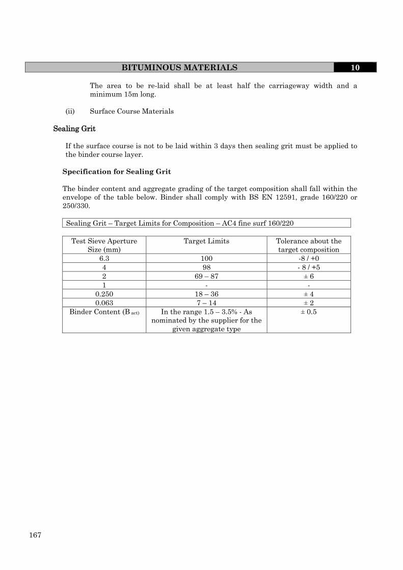
167
BITUMINOUS MATERIALS 10
The area to be re-laid shall be at least half the carriageway width and a
minimum 15m long.
(ii) Surface Course Materials
Sealing Grit
If the surface course is not to be laid within 3 days then sealing grit must be applied to
the binder course layer.
Specification for Sealing Grit
The binder content and aggregate grading of the target composition shall fall within the
envelope of the table below. Binder shall comply with BS EN 12591, grade 160/220 or
250/330.
Sealing Grit – Target Limits for Composition – AC4 fine surf 160/220
Test Sieve Aperture
Size (mm)
Target Limits Tolerance about the
target composition
6.3 100 -8 / +0
4 98 - 8 / +5
2 69 – 87 ± 6
1 - -
0.250 18 – 36 ± 4
0.063 7 – 14 ± 2
Binder Content (B act) In the range 1.5 – 3.5% - As
nominated by the supplier for the
given aggregate type
± 0.5

168
BLOCK PAVING FOR CARRIAGEWAYS 10
10.8 BLOCK PAVING FOR CARRIAGEWAYS
General
Block paving shall be of the conventional pavement type and restricted to pedestrian
areas including footpaths and to Category 5 roads (see section 5).
For other uses approval is required from the Engineer
Note – to ensure the successful use of block paving the Developers attention is drawn to
British Standard BS7533. This British Standard gives guidance on the minimum design
considerations and minimum standards for construction which the Engineer will expect
to be followed for areas offered for adoption. The terms and definitions given in BS7533
are used throughout this section.
(i) Paving Units (blocks)
Concrete paving blocks shall comply with the requirements given in BS EN 1338 and
shall have the following performance requirements.
a) Weathering requirements – all blocks shall be of class 3.
b) Abrasion requirements – all blocks shall be class 3
c) Slip resistance – blocks for predominately pedestrian use shall have, at the time of
installation, a wet slip resistance when measured in accordance with BS 7976 of not
less than 50.
d) Skidding resistance – blocks for vehicular areas shall have, at the time of
installation, a wet skidding resistance when measured in accordance with BS 7976
of not less than 55.
Note – Prior to the use of the proposed paving units the Developer is required to supply
to the Engineer a certificate of conformity showing compliance to the above minimum
requirements. In case of dispute then Audit / Compliance testing shall be in accordance
with BS EN 1338.
(ii) Clay Pavers
Clay pavers shall comply with the requirements given in BS EN 1344 and shall have the
following performance requirements.
a) Freeze / thaw resistance – all blocks shall be of classification FP100
b) Transverse breaking load – all blocks shall be of classification T4
c) Abrasion resistance – all blocks shall be classification A3
d) Slip / Skid resistance – blocks for predominantly pedestrian use shall be of class U1.
Blocks for vehicular areas shall be class U3
Note – Prior to the use of the proposed pavers the Developer is required to supply to the
Engineer a certificate of conformity showing compliance to the above minimum
requirements. In case of dispute then Audit / Compliance testing shall be in accordance
with BS EN 1344.
(iii) Paver / Block thickness
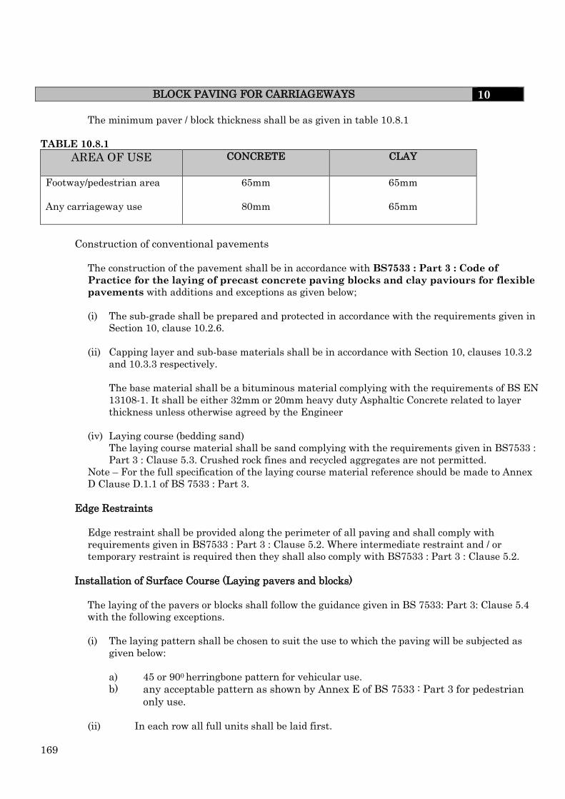
169
BLOCK PAVING FOR CARRIAGEWAYS 10
The minimum paver / block thickness shall be as given in table 10.8.1
TABLE 10.8.1
AREA OF USE
CONCRETE CLAY
Footway/pedestrian area 65mm 65mm
Any carriageway use 80mm 65mm
Construction of conventional pavements
The construction of the pavement shall be in accordance with BS7533 : Part 3 : Code of
Practice for the laying of precast concrete paving blocks and clay paviours for flexible
pavements with additions and exceptions as given below;
(i) The sub-grade shall be prepared and protected in accordance with the requirements given in
Section 10, clause 10.2.6.
(ii) Capping layer and sub-base materials shall be in accordance with Section 10, clauses 10.3.2
and 10.3.3 respectively.
The base material shall be a bituminous material complying with the requirements of BS EN
13108-1. It shall be either 32mm or 20mm heavy duty Asphaltic Concrete related to layer
thickness unless otherwise agreed by the Engineer
(iv) Laying course (bedding sand)
The laying course material shall be sand complying with the requirements given in BS7533 :
Part 3 : Clause 5.3. Crushed rock fines and recycled aggregates are not permitted.
Note – For the full specification of the laying course material reference should be made to Annex
D Clause D.1.1 of BS 7533 : Part 3.
Edge Restraints
Edge restraint shall be provided along the perimeter of all paving and shall comply with
requirements given in BS7533 : Part 3 : Clause 5.2. Where intermediate restraint and / or
temporary restraint is required then they shall also comply with BS7533 : Part 3 : Clause 5.2.
Installation of Surface Course (Laying pavers and blocks)
The laying of the pavers or blocks shall follow the guidance given in BS 7533: Part 3: Clause 5.4
with the following exceptions.
(i) The laying pattern shall be chosen to suit the use to which the paving will be subjected as
given below:
a) 45 or 900 herringbone pattern for vehicular use.
b) any acceptable pattern as shown by Annex E of BS 7533 : Part 3 for pedestrian
only use.
(ii) In each row all full units shall be laid first.
170
BLOCK PAVING FOR CARRIAGEWAYS 10
(iii) Closure pieces shall not be less than 1/3 of a full block and shall be cut by
mechanical means and are to be placed with a 3mm joint to edge restraint.
(iv) Infilling to boundaries and obstructions shall be completed as the laying proceeds
and prior to compaction.
(v) Laying around obstructions, e.g. manholes and gullies shall be in accordance with
BS 7533 : Part 3 : clause 5.4.3.2. Where ironwork or other features intrude into the
pavement they shall be chosen and installed to ensure the minimum amount of
cutting.
Where paving units do not fit neatly around an intrusion / obstruction a concrete
surround is to be provided. The concrete is to be either PAV1 or a C35 air entrained
mix conforming to BS EN 206-1. For work around intrusions / obstructions then the
Developers attention is drawn to the detail given in BS 7533: Part 3, fig. C.2 which
the Engineer requires to be followed.
(vi) Where concrete is used to in-fill then an acceptable colour match with the
surrounding paved area is to be obtained. Fine aggregate, pigment and mixes shall
be carefully selected to obtain the required colour match. The colour match shall be
tested by trial mixes before use on site. The acceptable mix and mix proportions
shall be recorded and submitted to the Engineer for future reference.
(vii) Uncompacted paved areas shall be protected at all times to prevent disturbance and
/ or vehicle use.
Compaction of paving units into the laying course
Compaction shall take place as soon as practically possible on completion of the
installation of the paving units using an approved vibrating plate compactor. The
installation shall be compacted by not less than three passes of the compaction
equipment. Compaction shall achieve the specified line and level.
All paving units within 1m of the laying face must be fully compacted prior to the
completion of the days work.
Paving units that are damaged during compaction shall be immediately removed and
replaced. Compaction shall continue until full compaction has been achieved and there is
no lipping between adjoining units.
The vibrating plate compactor shall be a high frequency, low amplitude mechanical
rubber soled flat plate with an area of not less than 0.25m2 transmitting a force of 75 to
100kN/m2 of plate area when operating at a frequency of 75Hz to 100Hz.
Joint filling after compaction.
It is essential for the paving to function correctly and to prevent premature failure that
the joints are filled immediately after compaction. The jointing material shall be dried
free flowing silica aggregate (sand) complying with the requirements given in BS 7533
Annex D, clause D.1.2.
The jointing material, which must not stain the surface of the pavement, shall be lightly
brushed over the pavers to fill the joints. The surface shall then be subjected to final

171
BLOCK PAVING FOR CARRIAGEWAYS 10
compaction to ensure complete filling of the joints. This process is to be repeated until the
joints are filled. All surplus jointing material shall then be removed from the surface
before trafficking. Where after trafficking the pavement shows evidence of joints that are
not filled then the above process shall be repeated.
Surface Regularity
Surface regularity shall comply with the requirements given in BS 7533 : Part 3 Annex
B, clause B.2. with the following additions:
(i) The maximum permissible deviation from design level overall for the finished
pavement is to be within the limits of +/- 6mm.
(ii) Adjacent to gullies, surface drainage, channels and outlets the maximum deviation
shall be +6mm to 0mm.
Note – the permissible deviations for the upper level of drainage inlets and channels
shall be +/- 0mm to ensure positive drainage.
Should there be settlement of any section of the pavement the Developer shall
investigate and determine the cause of the settlement and shall propose to the Engineer
remedial action to rectify the problem and prevent re-occurrence.
Sealing of the pavement
All block paved areas shall be sealed. The sealant shall be approved / recommended by
the block manufacturer and details submitted to the Engineer prior to sealing work
commencing. The Engineer may require a trial to ensure no staining of the blocks occurs
and that the sealant adequately stabilises the jointing material.
Note – vacuum sweepers should not be used on the surface for at least three months after
laying in order to reduce the risk of jointing material being lost.
Construction in adverse weather conditions.
In adverse weather conditions, units shall not be laid where the moisture content of the
laying course material is outside the limits given in BS 7533 : Part 3 : clause 5.3.2.1. The
filling of joints is not possible in wet and / or damp conditions.
Recessed Covers
Where a manhole/inspection cover is located within a block paved area a galvanised steel
recessed cover and complying with the appropriate British Standard should be used.
Infilling with blocks should be in a such manner as to match the surrounding pattern.

172
FOOTPATHS, FOOTWAYS AND CYCLETRACKS 10
10.9 FOOTPATHS, FOOTWAYS AND CYCLETRACKS
General
The construction of footpaths, footways and cycleways shall be in general accordance
with the requirements of Section 10.7 or unless amended by the following clauses.
The Developer must ensure that all relevant footpaths/footways are constructed to binder
course level (as a minimum) prior to occupation of dwellings.
Formation – Inspection and Approval
The formation shall be prepared to give a sound base on which to lay all of the
subsequent layers.
Trenches and other excavated areas below formation level are to be reinstated as
follows:-
(a) using sub-base materials placed in layers not exceeding 150mm thick and compacted
to refusal.
(b) using acceptable excavated materials.
Where the Developer proposes to use acceptable excavated materials as backfill to
excavations, then notification must be given to the Engineer to enable inspections to
be carried out as the backfilling operations progress.
Backfilling operations using acceptable excavated materials must be carried out in
accordance with NRSWA.
Where excavated materials are to be used, then operatives need to be trained and
certificated in the identification of backfill materials, field identification tests for
suitability of backfill materials and compaction of backfill materials in accordance
with the NRSWA.
If in the opinion, of the Engineer the operatives cannot fulfil the requirements of the
NRSWA – the use of excavated materials will not be permitted.
Sub-Base Materials
All footpath, footway and cycletracks shall have a granular sub-base complying with the
requirements of 10.3.3. The sub-base shall be of a nominal compacted thickness of
150mm. The construction detail is given in Sketches 9.3.1 and 10.4.1 for flexible
(bituminous) and modular constructions.
Note The detail given in Sketch 10.4.1 is required to prevent shrinkage
of the underlying formation material (usually clay of medium or high
shrinkage) from resulting in surface cracking particularly with
bituminous construction.

173
FOOTPATHS, FOOTWAYS AND CYCLETRACKS 10
Where cracking of the bituminous surfacing occurs then the Engineer will require
remedial works to be carried out. An investigation of the cracked areas may also be
required to ensure that the detail given in Sketch 10.4.1 has been followed.
Flexible (Bituminous) Construction
(i) Binder Course
The binder course material shall be 20mm Dense Asphaltic Concrete
complying with the requirements of BS EN 13108-1:2006. For hand laying
operations then the binder viscosity shall be selected from those given in
clause 10.7.4.
The binder course shall be laid to a nominal layer thickness of 50mm, shall be
fully compacted and free from areas of segregation, cracking and roller marks.
Compaction shall be achieved using a static 2.5t dead weight roller applying a
minimum of 4 passes.
(ii) Surface Course (Footpath/Footway)
The surface course material shall be 6mm Dense Asphaltic Concrete
complying with the requirements of BS En 13108-1:2006. For hand laying
operations the binder viscosity shall be selected from those given in Clause
10.7.4.
The surface course shall be laid to give a nominal layer of thickness of 20mm shall
be fully compacted and shall be free from areas of segregation, cracking and roller
marks. The finished surface shall be laid flush with the kerb.
Compaction shall be achieved using a static 2.5t dead-weight roller applying a
minimum of 4 passes.
(iii) Surface Course (Cycletrack)
The surface course shall be of a 6mm Dense Asphaltic Concrete material to
give a red colour acceptable to the Engineer in accordance with clause 10.7.7.
It shall be laid to give a nominal thickness of 20mm be fully compacted and be
free from areas of segregation, cracking and roller marks. The finish surface shall
be laid flush with the kerb.
Compaction shall be achieved using a static 2.5t dead weight roller applying a
minimum of 4 passes.
Note: It is recommended that those involved in the laying of red
pigmented bituminous materials seek advice on acceptable laying
practises form the supplier of such material before work
commences on site.
174
FOOTPATHS, FOOTWAYS AND CYCLETRACKS 10
Adhesion Between Layers
Where the binder course layer is to remain uncovered for more than 3 days after laying
then it shall be sealed by the application of sealing grit complying to the requirements of
BS4987 – Clause 7.9. The rate of spread of the sealing grit shall be such as to prevent the
underlying binder course becoming contaminated with clay dirt etc. Failure to prevent
contamination of the binder course may result in rejection of that layer.
Prior to the laying of the surface course, the footpath binder course shall be cleaned and
have a tack coat applied to the satisfaction of the Engineer. The tack coat specification
and application shall be a given as Clause 10.7.5.
Footpath Vehicular Crossing
(i) Residential
At each vehicular crossing the sub-base shall be thickened to 225mm and the
binder course to 60mm, making the overall construction depth 305mm. The
construction details are given in sketch 10.9.1.
(ii) Industrial
The footpath or vehicle crossing shall be constructed to give a finished
construction as given in Clause 6.2.8 and Sketch No. 6.2.2.
Note: The mesh reinforcement shown in Sketch No. 6.2.2 may be replaced
with fibre reinforcement. Where fibre reinforcement systems are to be
used, then the Developer must provide the Engineer with all the
relevant information before the works commence. This information
must include – fibre type, point of introduction into the concrete,
dispersion throughout the concrete.
Surface Level Tolerances
The permitted deviation of the surface level of any footpath, footway or cycletrack layer
at any point from the true surface level shall not exceed the following values:-
(i) formation to receive sub-base +0mm/-30mm
(ii) sub base to receive binder course +0mm/-15mm
(iii) binder course to receive surface course +5mm/-5mm
(iv) surface course +5mm/-0mm
Storage of Bituminous Materials
When stored on site, the material shall be retained in such a manner, as to ensure no
deterioration of adjacent or underlying surfaces and that the material retains its
workability.

175
FOOTPATHS, FOOTWAYS AND CYCLETRACKS 10
Laying of Bituminous Materials
The conditions given in Clause 10.7.13 shall equally apply to the laying of footpath,
footway or cycleway materials.
Laying shall proceed continuously so as to limit the number of joints, particularly in
surface course operations, to a minimum. All joints shall be cut back to a sound edge
prior to the commencement of the days work. All surface course vertical joints shall be
coated with a joint sealant approved by the Engineer.
Compaction shall be applied uniformly across the full width of the footpath, footway or
cycletrack and shall be substantially complete while the material is in a workable
condition. Particular care will be required around footpath furniture which will
necessitate hand compaction using a hand tamper.
Areas of segregation and/or surface cracking due to poor rolling technique will result in
the rejection of the surfacing.
Surface Regularity
Where the Engineer considers that the surface regularity of the footpath, footway or
cycletrack may affect the end use of these surfaces then the surfacing layers (binder
course and surface course) shall be checked using the apparatus and test method given in
the Specification for Highway Works – series 7 – Clause 702 (i.e. the rolling straight edge
method) with the exception that it shall be carried out at any time specified by the
Engineer. The surfacing shall not exhibit any irregularity greater than 5mm.
Modular Construction
The use of modular construction systems shall only be permitted with the approval of the
Engineer.
(i) Precast Concrete Flags (PCC) Including Tactile Crossing Flags
The flags shall comply with the requirements of BS 7263-1 and shall be of
minimum thickness 63mm. Flags shall have the following performance
requirements:
(a) Weathering resistance – all flags shall be of class W2.
(b) Abrasion resistance – all flags shall be of class A2.
(c) Slip/skid resistance – flags for predominately pedestrian use shall be of class
S2. Flags for vehicular use shall be of class S3.
Note: Testing the above performance requirements shall be in accordance with the
relevant annex of BS 7263-1.

176
FOOTPATHS, FOOTWAYS AND CYCLETRACKS 10
(ii) Laying of Precast Concrete Flags
Precast concrete flags shall be laid in accordance with the requirements given in
BS 7533: Part 4 to give a finished construction as detailed in sketch 10.4.1.
(iii) Concrete and Clay Paving Blocks
Concrete paving blocks shall comply with the requirements of BS 6717 and shall
have the following performance requirements:
(a) Weathering resistance – all blocks shall be of class W2.
(b) Abrasion resistance – all blocks shall be of class A2.
(c) Slip resistance – blocks for pedestrian use shall be of class S2.
Note: Testing the above performance requirements shall be in accordance with the
relevant annex of BS6717.
Clay paving blocks shall comply with the requirements of BS6677: Part 1.
(iv) Laying of Blocks
The blocks shall be laid in accordance with the requirements of Section 8.8.
(v) Sealing
The paved area shall be sealed with a proprietary solution approved by the
Engineer, after satisfactory joint standing.
Adjustment of Utility Covers
The Developer shall be responsible for the adjustment to all manhole covers, hydrants,
services, boxes, gullies etc to suit the finished footpath, footway or cycletrack level to the
satisfaction of the Engineer.
Tying into Existing Work
(i) Bituminous
Where new works abuts existing work, then a butt joint shall be formed. The
existing work, where required, shall be cut to form a vertical face which is clean
and dust free. This face shall be painted with a bituminous sealant to the
satisfaction of the Engineer.
The new work shall be adjusted and/or reshaped as directed by the Engineer to
match the existing.
(ii) Modular
Where a modular footpath is required to tie into existing then the new works
shall match the existing in both line and level and any existing bonding pattern
shall be maintained.
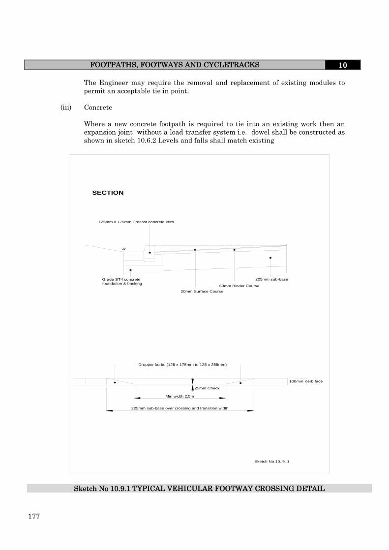
177
FOOTPATHS, FOOTWAYS AND CYCLETRACKS 10
The Engineer may require the removal and replacement of existing modules to
permit an acceptable tie in point.
(iii) Concrete
Where a new concrete footpath is required to tie into an existing work then an
expansion joint without a load transfer system i.e. dowel shall be constructed as
shown in sketch 10.6.2 Levels and falls shall match existing
Sketch No 10.9.1 TYPICAL VEHICULAR FOOTWAY CROSSING DETAIL
Sketch No 10. 9. 1
Dropper kerbs (125 x 175mm to 125 x 255mm)
25mm Check
Grade ST4 concrete
foundation & backing
125mm x 175mm Precast concrete kerb
225mm sub-base
'A'
60mm Binder Course
20mm Surface Course
100mm Kerb face
Min width 2.5m
225mm sub-base over crossing and transition width
SECTION

178
REINSTATEMENT 10
10.10 REINSTATEMENT
General
The Developer is responsible for all reinstatements until adoption.
Excavation
All excavations shall be carried out in such a manner to avoid damage to the surrounding
construction. Excavations shall avoid damage to tree roots.
Trench walls shall be even and vertical with no undercutting of the surrounding
construction. Where any undercutting does occur then the void shall be filled as soon as
practicable to the satisfaction of the Engineer.
The sides of the excavation shall be supported in accordance with the mandatory
requirements of Health and Safety.
Supports shall be withdrawn in co-ordination with backfilling and compaction operations
and all voids carefully filled and compacted.
Excavations shall as far as possible be protected from the ingress of water. Excess water
in trenches shall be pumped to an approved disposal point.
Bituminous surfacing – each layer shall be "stepped" as shown in Sketch 10.10.1.
Concrete surfacing – shall be cut to the full depth of the concrete.
Modular construction – existing units shall be lifted and stored for reuse. Edge restraint
must be provided to all unaffected areas.
Backfill Materials
(i) Carriageways
Backfill materials shall be approved capping or sub-base materials as specified in
Section 10.3 and shall be placed in layers not exceeding 200mm or 150mm thick
respectively and compacted to refusal.
Where capping is used for backfilling the operation must stop at the base of the
existing sub-base. Where sub-base is used for backfilling the operation may
continue up to and including the sub-base level.
With the approval of the Engineer foamed concrete, complying with the
requirements of the Specification for the Reinstatement of Openings in Highways,
may be used up to and including the sub-base layer.
(ii) Footways, Footpaths and Cycletracks
The backfill materials and operation shall comply with the requirements given in
Section 10.9.
179
REINSTATEMENT 10
Note A guide to compaction requirements is given in Appendix A8 of the
Specification for the Reinstatement of Openings in Highways.
Sub-Base
Where a granular sub-base is used it shall comply with the requirements given in Clause
8.3.3 and shall be compacted using compaction plant approved by the Engineer and shall
be compacted to refusal.
Bituminous Base (Road Base) and Binder Course
Where reasonably possible bituminous materials used in reinstatements shall be
machine laid. Hand laying will only be permitted with the prior approval of the
Engineer. Bituminous materials shall comply with the requirements of Section 10.7.
Bituminous Surface Course
(i) General
Where reasonably possible surface course reinstatements will be machine laid.
Hand laying will only be permitted with the prior approval of the Engineer.
Where it is necessary to carry out reinstatement to material with a red pigmented
binder then the Developer shall ensure that the reinstatement matches the existing
for colour, texture and surface finish.
Note Reference should be made to the original supplier of the "red" material as the
best means of obtaining the match as required above.
(ii) Location of Trench Related to Reinstatement Required
Where a trench runs longitudinally in the carriageway then it's location within the
carriageway will dictate the reinstatement requirements as follows:-
(a) Within a half carriageway width – the surface course over the half carriageway
must be removed and replace.
(b) Along to carriageway centre line – the full carriageway width must be removed
and replaced.
(c) In a footpath, footway or cycletrack – the full width must be removed and
replace.
Note - For footpath, footway or cycletrack surface course reinstatement of this nature,
alternatives to full removal may be submitted to the Engineer for consideration
180
REINSTATEMENT 10
.
Modular
Where the reinstatement of modular surfacing is necessary then it shall be carried out in
accordance with the requirements of BS 7533 : Part 11.
(i) General
It is permitted to reuse modular units that have been removed, cleaned, and then
stored during the reinstatement operations. Those modular units, which in the
opinion of the Engineer, are unfit to be reused shall be discarded and replaced by
units which match the original works in all respects.
(ii) Extent of Reinstatement
Remove an additional 1m of units from around the reinstated area including any
units which have been disturbed during the excavation, backfilling and
reinstatement operations. The reinstatement shall be carried out in accordance with
the requirements of Sections 10.8 and 10.9.

181
REINSTATEMENT 10
Trench
Saw Cut
Saw Cut
Surface Course
Binder Course
Base
Sub Base
CARRIAGEWAY
FOOTWAY / CYCLETRACK
Sub Base
Trench
Binder Course Surface Course
75mm
NOTES
1. The depth and type of reinstatement materials are specified in Section 8.10
2. Where a trench runs longitudinally in the carriageway, footway or cycletrack then the width of surface course reinstatement shall be as specified in Clause 10.10.6(ii). Where a trench runs across the carriageway the step width shall be 150mm minimum.
Where a trench runs across the footway or cycletrack the step width shall be 75mm minimum.
See note 2
150mm
150mm
150mm
150mm
See note 2
75mm
Sketch No. 10.10.1 TYPICAL SECTIONS FOR TRENCH REINSTATEMENTS
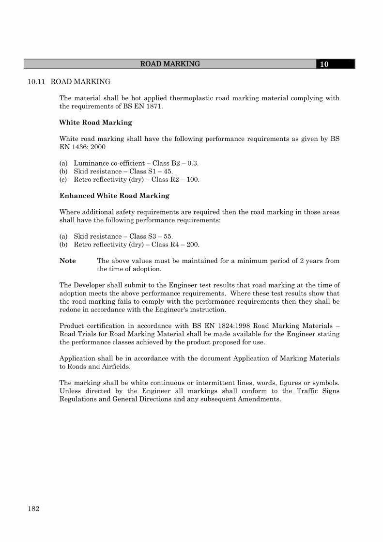
182
ROAD MARKING 10
10.11 ROAD MARKING
The material shall be hot applied thermoplastic road marking material complying with
the requirements of BS EN 1871.
White Road Marking
White road marking shall have the following performance requirements as given by BS
EN 1436: 2000
(a) Luminance co-efficient – Class B2 – 0.3.
(b) Skid resistance – Class S1 – 45.
(c) Retro reflectivity (dry) – Class R2 – 100.
Enhanced White Road Marking
Where additional safety requirements are required then the road marking in those areas
shall have the following performance requirements:
(a) Skid resistance – Class S3 – 55.
(b) Retro reflectivity (dry) – Class R4 – 200.
Note The above values must be maintained for a minimum period of 2 years from
the time of adoption.
The Developer shall submit to the Engineer test results that road marking at the time of
adoption meets the above performance requirements. Where these test results show that
the road marking fails to comply with the performance requirements then they shall be
redone in accordance with the Engineer's instruction.
Product certification in accordance with BS EN 1824:1998 Road Marking Materials –
Road Trials for Road Marking Material shall be made available for the Engineer stating
the performance classes achieved by the product proposed for use.
Application shall be in accordance with the document Application of Marking Materials
to Roads and Airfields.
The marking shall be white continuous or intermittent lines, words, figures or symbols.
Unless directed by the Engineer all markings shall conform to the Traffic Signs
Regulations and General Directions and any subsequent Amendments.

183
DESIGN GUIDE AND SPECIFICATION FOR STREET LIGHTING 11
For Local variations in Stockton and Redcar and Cleveland please see Local
Variations page at front of this document
11.0 STREET LIGHTING
11.1 GENERAL
All developments must be provided with an approved form of street lighting prior to
being considered eligible for adoption. It should be noted that the Highway
Authority will not be responsible for any street lighting erected in non-adoptable
situations. Proposals for street lighting must be included with the drawings and
specifications to be incorporated in the Section 38 Agreement. The provision of street
lighting will be the responsibility of the Developer and all proposals must have the
approval of the Engineer prior to works commencing.
The Developer must ensure that all relevant street lighting is operational before
occupation of dwellings.
11.2 REGULATIONS AND BRITISH STANDARDS
Street lighting designs must comply with the current editions of the following: -
BS5489
BS5489-1 : 2003 Code of practice for the design of road lighting-
Part 1: Lighting of roads and public amenity areas.
BS5489-2 : 2003 Code of practice for the design of road lighting-
Part 2: Lighting of tunnels and underpasses.
BS EN 13201 Road Lighting.
BS EN 13201-2 : 2003 Part 2 : Performance requirements.
BS EN 13201-3 : 2003 Part 3 : Calculation of performance.
BS EN 13201-4 : 2003 Part 4 : Methods of measuring performance.
All components and materials must comply with the relevant British Standards.
The Highway Authority will consider any other light source that may become
Available subject to the approval of the Engineer. Consideration will be given to Best
Value when selecting light sources and also by not compromising the quality of the
lighting installation. Lanterns shall incorporate electronic control gear obtained from
an approved manufacturer.

184
DESIGN GUIDE AND SPECIFICATION FOR STREET LIGHTING 11
Street lighting and associated electrical installations must comply with the
following:-
(i) The current edition of the IEE Regulations (BS7671) with particular
reference to section 611 (Highway Power Supplies and Street
Furniture).
(ii) The requirements of the R.E.C. with particular reference to requirements for
obtaining a metered supply for loads exceeding 500w originating from a single
electrical exit point.
(iii) G39/1 (Regional Electricity Companies publication) with particular regard to
sighting of columns in the vicinity of overhead lines.
(iv) The Electricity at Work Regulations.
(iv) Guidance Note GS6 (HSE) – Avoidance of Danger from Overhead Electricity
Lines.
(v) Should overhead electricity lines cross the site the Developer must seek
approval from the Electricity Generator and/or Supplier as appropriate before
erecting any columns in the vicinity of the lines.
(vii) Where columns are sited in the vicinity of high voltage overhead lines a warning
notice “DANGER HIGH VOLTAGE OVERHEAD CABLES” must be fixed to
the columns adjacent to the lines as a warning to street lighting operatives
carrying out future maintenance requirements. The sign is to be manufactured
from 3mm thick approved plastic substrate material and fixed by an approved
method.
11.3 DESIGN REQUIREMENTS
(i) Compliance with this specification will still leave a wide range of choice for the
Developer. All products complying with British Standards are not necessarily
acceptable and therefore proposals must be submitted at an early stage to the
Engineer for approval.
(ii) The Developer’s lighting design proposals, including illuminance data in the
form of grid diagrams together with electrical cable calculations, must be
submitted for approval to the Engineer.
(iii) It is essential to ensure that the type and heights of lighting columns is
appropriate for the development proposals. Local distributor roads will require
mounting heights of 8m or 10m. Mounting heights on proposed bus routes
(iv) must be a minimum of 6m. Mounting heights of 6m will also be required on
other estate roads, unless otherwise agreed with the Engineer.
(v) A column mounting height of 8m is to be used for industrial estate roads unless
directed otherwise by the Engineer
185
DESIGN GUIDE AND SPECIFICATION FOR STREET LIGHTING 11
(vi) Columns shall be positioned at the back of footways/footpaths, or verges within
the adopted highway approximately 1.8m from carriageway edge.
(vii) Columns must not obstruct footways/footpaths, vehicular accesses or be sited in
potentially hazardous positions. They shall be sited in accordance with the
recommendations in BS 5489-1 2003 section 5.2 and subject to the conditions of
Statutory Undertakers. Particular regard should be given to safety clearances
from lighting columns and any overhead electricity line which may cross the
development.
(viii) Where a new road is constructed connecting to an existing highway it may be
necessary for the Developer to upgrade the existing lighting or provide
additional columns as directed by the Engineer. The lighting layout at the
junction must be in accordance with BS 5489-1 2003 Annex J.
(ix) Where traffic calming humps are installed they should be illuminated in
accordance with BS 5489-1 2003 Annex A.5 (as sketch 11.3.1)
(x) Due to the range of lamps and lamp sizes acceptable for residential development
the Developer is advised to contact the Engineer to agree the type, wattage and
colour of the lamp to be used prior to commencing design.
(xi) It should be noted that the Highway Authority will not be responsible for any
street lighting erected in non-adoptable situations.
(xii) Street lighting for residential areas shall be designed in accordance with the
following:-
(a) Local Distributor Roads / Primary Access Roads / Industrial Estates
BS EN 13201-2 2003 section 4 tables 1a / 1b (ME Class)
(b) All other residential roads BS EN 13201-2 2003 section 6 table 3 (S Class)
(xiii) Where columns are to be looped from an REC supply point within a Column the
Developer shall provide a fused cut-out as specified in Clause 11.10
incorporating a separate HRC fuse (BS88) to protect the outgoing looped circuit,
(see Sketch 11.17.1). This method of connection shall be limited to 6 No.
columns and a maximum load of 500w.
(xiv) A suitably approved Feeder Pillar shall be provided when connecting more than
6 No. columns to an REC supply point. No more than 6 No columns shall be fed
from any individual circuit unless approved by the Engineer. The Feeder Pillar
shall incorporate a suitable double pole, lockable switch, HRC Fuseboard, The
enclosure is to be protected with a suitably agreed external vandal resistant
locking mechanism.

186
DESIGN GUIDE AND SPECIFICATION FOR STREET LIGHTING 11
11.4 LIGHTING EQUIPMENT ON BUILDINGS
Consideration should be given to attaching lighting units to buildings to reduce
street clutter. Where lighting units are to be attached to a building, an agreement
will be required between the freeholder of the property, any
existing tenants and the highway/lighting authority, this agreement must also be in
perpetuity. It may also be necessary to enter into an agreement with all the other
properties within a street/development in case of future redesign of the lighting
schemes.
It is important that during the design of wall mounted schemes that measures are
put into place to reduce stray light, as this could be considered as nuisance.
Developers should inform buyers of properties with wall mounted street lights, of
cable routes and their responsibilities.
11.5 TYPE OF COLUMNS
(i) Hot Dipped Galvanised Steel columns shall be utilised for a mounting height of
6m. (or as agreed with the Engineer). The bracket shall be an integral part of
the column having the same diameter as the column shaft. The bracket shall
not project more than 450mm with a 5 degree uplift
(ii) In areas not accessible to maintenance vehicles, a steel hinged raising a
lowering column shall be used with post top or side entry lantern suitably
adapted to fit directly onto the column shaft. An approved lowering mechanism
is to be provided to the engineer prior to adoption of the installation in allowing
for future sustainable maintenance.
(iii) Hot Dipped Galvanised Steel columns shall be utilised for a mounting height of
8m or 10m. and Galvanised Sheet Steel for 12m columns. In addition the
columns shall be fitted with a removable 5 degree uplift bracket arm
incorporating an anti-rotational device. The bracket arm shall not exceed 1.0mt
in length. (unless agreed prior to installation with the Engineer). All rigid
columns are to be provided with an agreed tamper resistant locking
mechanism.
Lighting columns manufactured from alternative materials including stainless steel,
extruded 6000-grade aluminium and advanced polymer composite materials are now
becoming available. Each of these materials offers the potential of long service life
with minimal maintenance requirements and can be considered, subject to the
approval of the Engineer.
Where it is known that lighting columns are to be used to support additional loads
such as traffic signs, flower baskets, banners / flags and decorations the column shall
be designed to carry the additional load.

187
DESIGN GUIDE AND SPECIFICATION FOR STREET LIGHTING 11
11.6 COLUMN PROTECTION/IDENTIFICATION
Street lighting columns shall be hot dipped galvanised to BS 729.
Following erection columns shall be T washed, and have one coat of Mebopro 80, Or
similar approved product, and one coat of Ameron Steelbond 2134 applied before
handover. The colour to be grey to RAL 18B25.
A 2 pack epoxy resin protective coating, to the approval of the Engineer, shall be
painted over the base section of the column for a distance equal to the planting depth
plus 150mm.
Colour contrast bands on poles and columns to help partially sighted people will be
required. This will be a single white or yellow band 150 mm deep with its lower edge
between 1.5 m and 1.7 m from the ground. On completion of painting the column
shall be provided with an individual Identification number as follows:-
(a) Columns are to have numbers painted on one side of the column facing the
general direction of oncoming traffic or as otherwise directed by the
Engineer.
(b) The numbers shall be black and painted on a yellow background using
appropriate stencils and located at 1.8m above ground level. The height of the
numbers shall be 40mm. The size of yellow background shall be adequate to
accommodate the numbers.
(c) The type of paint used shall be submitted to the Engineer for approval
purposes.
(d) The column identification will comprise of up to 8 digits and the actual
numbers will be provided by the Engineer.
(Please go to page iii for variations in Redcar and Cleveland)
11.7 ERECTION OF COLUMNS, BRACKET ARMS AND LANTERNS
(i) The columns/lanterns are to be erected in the locations as shown on the
approved drawings.
(ii) Columns shall be erected with adequate mechanical handling plant. Where
cranes are used, it shall be ascertained that these, together with any
associated equipment, are suitable for the loads to be lifted.
(iii) Tower ladders or equivalent mechanical platforms shall be used for any work
undertaken at higher levels.
(iv) Holes shall be excavated by hand or approved mechanical means to the
appropriate column planting depth. The width of holes shall be kept to a
minimum compatible with the ground conditions and should not exceed the
width of the flag paced under the base of the column. The maximum width of
the flag shall be approximately twice the width of the column base. The
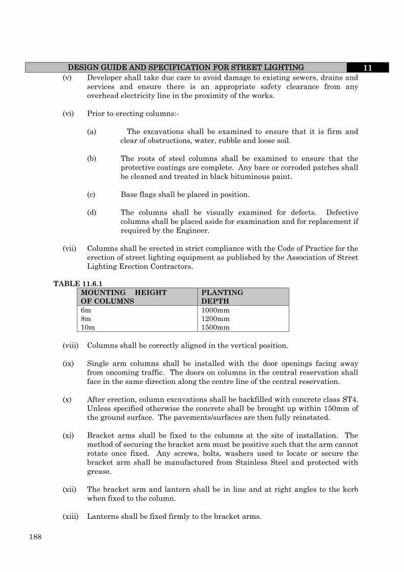
188
DESIGN GUIDE AND SPECIFICATION FOR STREET LIGHTING 11 (v) Developer shall take due care to avoid damage to existing sewers, drains and
services and ensure there is an appropriate safety clearance from any
overhead electricity line in the proximity of the works.
(vi) Prior to erecting columns:-
(a) The excavations shall be examined to ensure that it is firm and
clear of obstructions, water, rubble and loose soil.
(b) The roots of steel columns shall be examined to ensure that the
protective coatings are complete. Any bare or corroded patches shall
be cleaned and treated in black bituminous paint.
(c) Base flags shall be placed in position.
(d) The columns shall be visually examined for defects. Defective
columns shall be placed aside for examination and for replacement if
required by the Engineer.
(vii) Columns shall be erected in strict compliance with the Code of Practice for the
erection of street lighting equipment as published by the Association of Street
Lighting Erection Contractors.
TABLE 11.6.1
MOUNTING HEIGHT
OF COLUMNS
PLANTING
DEPTH
6m
8m
10m
1000mm
1200mm
1500mm
(viii) Columns shall be correctly aligned in the vertical position.
(ix) Single arm columns shall be installed with the door openings facing away
from oncoming traffic. The doors on columns in the central reservation shall
face in the same direction along the centre line of the central reservation.
(x) After erection, column excavations shall be backfilled with concrete class ST4.
Unless specified otherwise the concrete shall be brought up within 150mm of
the ground surface. The pavements/surfaces are then fully reinstated.
(xi) Bracket arms shall be fixed to the columns at the site of installation. The
method of securing the bracket arm must be positive such that the arm cannot
rotate once fixed. Any screws, bolts, washers used to locate or secure the
bracket arm shall be manufactured from Stainless Steel and protected with
grease.
(xii) The bracket arm and lantern shall be in line and at right angles to the kerb
when fixed to the column.
(xiii) Lanterns shall be fixed firmly to the bracket arms.

189
DESIGN GUIDE AND SPECIFICATION FOR STREET LIGHTING 11
(xiv) The lamps and all parts of the lantern affecting the photometric performance
shall be cleaned before the lamp is installed.
(xv) The whole of the equipment shall be effectively earthed and all exposed metal
parts of columns, lanterns and equipment shall be earthed in accordance with the
current Edition of the IEE Regulations (BS7671).
11.8 INTERNAL WIRING OF COLUMNS
(i) The Developer shall (via the Electricity supplier) fix the fused cut-outs onto the
baseboard provided in the control gear compartment. Only brass screws shall be
used.
(ii) Internal wiring from the fused cut-out to the lantern, control gear and
photoelectric cell shall be single or multicore copper conductor cables, 600/1000
volt grade PVC insulated and sheathed and shall comply with BS 6004.
(i) All earth continuity bonding conductors shall be sized in accordance with the
requirement of the IEE Regulations.
(ii) The minimum size of internal wiring shall be 2.5mm2.
(iii) See sketch no. 11.7.1.
11.9 TYPE OF LANTERNS
All lanterns shall be vandal resistant and shall be high pressure sodium lanterns with
completely sealed optic or similar to be approved by the Engineer with a minimum IP
rating 66 with integral control gear.
The lantern shall be complete with Nema Socket or Miniature Photo Electric Cell.
11.10 PHOTO ELECTRIC CONTROL (PECU)
The PECU shall be a miniature type or suitable to fit a standard NEMA socket.
The unit shall have a minimum guarantee of 6 years and be capable of switching a 10
amp inductive load with a switching ratio of 1 to 0.5 operating within a temperature
range of –20 to +70. The switch setting shall be clearly identified at 70 lux and operate
between the voltage variations from 200v to 260v AC. The unit shall be hermetically
sealed with an IP67 rating utilising a self cleaning configuration contained within an
impact resistant translucent housing.
The switching mechanism shall incorporate an Electronic Triggering
Circuit utilising a transformer power supply capable of withstanding
a 1.5KV flash test providing a voltage regulation of 20% or better
combining a relay and triac operation in a parallel mode.
11.11 FUSED CUT OUTS
Where street lighting columns are to be energised via public lighting cables, the fused
cut-out shall fully comply with the IEE current edition of the Wiring Regulations and

190
DESIGN GUIDE AND SPECIFICATION FOR STREET LIGHTING 11
shall provide a Double Pole, Switched, lockable 32A Isolator incorporating a BS 88 HRC
fuse category 240AC 16. Class Q1 of the appropriate rating.
The fuse cut out shall be complete with a cast brass earth plate suitable for terminating
PVC/SWA/PVC cables.
11.12 UNDERGROUND CABLES
(i) Underground cables shall be 2 core with copper conductors and shall be either:
(a) PVC insulated, PVC sheathed, steel wire armoured, PVC served overall
600/1000V grade and must comply to BS6346.
or
(b) Cross linked polyethylene steel wire armoured, 600/1000V grade and must
comply to BS5467.
(ii) The cables must be BASEC approved.
(iii) The minimum size of underground cables shall be 6mm2.
11.13 UNDERGROUND CABLE INSTALLATION
(i) All cables shall be laid in accordance with Section 611 of the current Edition of
the IEE Wiring Regulations.
(ii) Cables shall be installed only in complete lengths between column/column,
column/sign and column/feeder pillar. No jointing of part lengths will be allowed.
(iii) (a) The cables shall be laid in trench to a depth of cover of 450mm below
finished ground level.
(b) The cables shall be laid on 75mm thickness of sand, with a further
75mm of sand placed over the cable.
(c) Cable identification tape shall be laid approximately 250mm above the cable.
(d) Trenches shall be backfilled and compacted with suitable material free from
flints, stones or other sharp objects injurious to the cable.
(e) The finished level shall be the same as that of the surrounding level.
11.14 ELECTRICITY SUPPLY
The Developer must make satisfactory arrangements with the electricity supplier for the
electricity supply for the street lighting installation and to ensure that all necessary
cross-road ducts are provided before the carriageways are constructed. Should a
developer decide to appoint an alternative DNO to the local DNO for the provision of the
supply cable network onto a site it would be the responsibility of the appointed DNO to
respond to any future network supply faults as no reciprocal agreement between DNO’s
are currently in place. If this were the case the street lighting would have to be placed on

191
DESIGN GUIDE AND SPECIFICATION FOR STREET LIGHTING 11
a loop with a direct feed via a feeder pillar to the local DNO’s cables. It must be stated at
the time of the street lighting submission if an alternative DNO is to be used
11.15 COMPLETION OF WORKS
The lighting works shall be carried out to an approved standard and completed prior to
the occupation of properties. The Developer shall be responsible for the protection of
units after erection and until such time as the lighting works are taken over. The
Highway Authority will accept responsibility for energy charges when installation is
satisfactorily complete and following the issue of the part 2 Certificate (Refer to Clause
3.9.2).
11.16 TEST CERTIFICATE
Prior to the issue of the Part 2 Certificate – (refer to Clause 3.9.2) the whole of the street
lighting network shall be tested in accordance with the IEE Regulations and recorded on
forms ET1 and ET2 respectively (see Appendix 11.1 and 11.2). This information shall be
submitted to the Engineer together with the data collection record sheet, (see Appendix
11.3) and “as fitted” electrical records drawings showing full details of all electrical
circuits and cable runs.
11.17 UNDERGROUND CABLE IDENTIFICATION
All cables coming into columns should be identified as shown in Sketch 11.16.1.
11.18 SKETCHES
Public lighting supply details are shown on Sketches 11.17.1 to 11.17.3.
11.19 STREET FURNITURE – SIGNAGE
The specification for street furniture requiring electrical services will comply with the
following:
(i) In allowing for sustainable maintenance, agreement is required from the
Engineer as to the manufacturer and unit type proposed for the installation,
this could accommodate for either internally or externally illuminated sign
light units.
(ii) Suitably designed for weight and windage, hot dipped galvanised tubular steel.
(iii) 32a DP combined isolator and fuse unit (cut out) in the base of the signpost as
a means of local independent electrical isolation.
(iv) Miniature photo electric cell (PEC) fitting in accordance with Clause 11.10.
(v) All unique external unit referencing will be allocated for identification
purposes in accordance with Clause 11.6.
(vi) Class 1 diamond grade legends on either GRP, steel, or aluminium base units.
(vii) External site protective coating application in accordance with Clause 11.5.

192
DESIGN GUIDE AND SPECIFICATION FOR STREET LIGHTING 11
(viii) The minimum mounting height shall be 2.45 metres to underside of sign plate.
(ix) Prior to the issue of the Part 2 Certificate (refer to Clause 3.9.2) for each Street
Furniture item with an electrical supply the following must be submitted to
the Engineer:
Data Verification form (DV)
Electrical Test Certificate (ET1)
Electrical Test Certificate (ET2) where applicable
The location of underground cable routes for supply purposes must be
submitted as “fitted drawings” in an approved format.
11.20 DISCONNECTION OR TRANSFER OF STREET FURNITURE
The developer is required to contact the relevant authority with regards to the removal or
transfer of any street furniture installation.

193
DESIGN GUIDE AND SPECIFICATION FOR STREET LIGHTING 11 Appendix 11.1 TEST & INSPECTION CERTIFICATE –INTERNAL COLUMN/WIRING ET1
TEES VALLEY COUNCIL’S TEST & INSPECTION CERTIFICATE – INTERNAL COLUMN/SIGN WIRING
VISUAL INSPECTION SIZE Correct Failure Reason
Earthing Conductors:
ELECTRICAL TESTING
I CERTIFY THAT TO THE BEST OF MY KNOWLEDGE AND BELIEF THE ABOVE INSTALLATION HAS BEEN INSPECTED AND
TESTED IN ACCORDANCE WITH THE CURRENT EDITION OF BS 7671 – IEE WIRING REGULATIONS
Column/Sign/Bollard Reference No:
Column/Sign/Bollard Location:
ET1
Unit Type: Height: Bracket:
Wattage of Lantern: Control
Gear:
Supply of Source
Type of
Earthing:
Circuit Protection Fuse BS
Type::
Rating Amps
MBC
Class:
RCD Type: Limiting Impedance
(Ohms)
Identification of conductors
Size of circuit conductors
Earth
Terminal:
(a) Main equipotential bonding
conductor:
(b) Armour earthing continuity
conductor:
(c) Circuit protective conductor:
Earth cables sleeved:
Insulation of Live Parts (i.e. IP2X)
Fuse Unit of Live
Shroud:
Neutral
Shroud
Is Capacitor fitted? Is light working?
Insulation Resistance Phase/Protective (ohms) Neutral Protective
(ohms)
Polarity Satisfactory
Nominal Voltage
(volts)
Earth Fault Loop Impendance at Fuse Unit
(ohms)
Earth Electrode (where applicable) (ohms)
RCD (Where applicable) m.sec.
Comments/Corrective Action:
Testers Name Test Date
Signature
e

194
DESIGN GUIDE AND SPECIFICATION FOR STREET LIGHTING 11 Appendix 11.2 TEST AND INSPECTION CERTIFICATE LIGHTING CABLE NETWORK ET2
TEST AND INSPECTION CERTIFICATE –
LIGHTING CABLE NETWORK (ET2)
Location Ref No:
Source (F/pillar/column/E) Circuit:
Cable: System and
Earthing Type:
Circuit protection: Fuse Rating(A): Limiting
BS No: Impedance (OHMS):
MBC
Class
1.
2.
3.
4.
5.
6.
7.
8.
Report Ref No:
Visual Inspection: Satisfactory? Yes No
Earth Electrode Resistance (OHMS)
(where applicable)
Insulation Resistance (M OHMS)
R-B R-Y Y-B R-N Y-N B-N R-E Y-E B-E N-E
Polarity: Satisfactory? Yes No
Earth Fault Loop Impedance (OHMS)
Source:………………………………………………………………………………..Remote End:……………………………………
RCCB Operation (where applicable)
Manufacturers Value:…………………………………………………………..Test Value:…………………………………………..
Voltage drop (@ full load – V)
Source:………………………………………..Remote End Voltage:…………………………………Volt Drop:……………………
Comments:
I CERTIFY THAT TO THE BEST OF MY KNOWLEDGE AND BELIEF THE ABOVE INSTALLATION HAS BEEN
INSPECTED
AND TESTED IN ACCORDANCE WITH THE CURRENT EDITION OF THE IEE WIRING REGULATIONS
Print Name:…………………………………………………………..Signature………………………………………Date / /
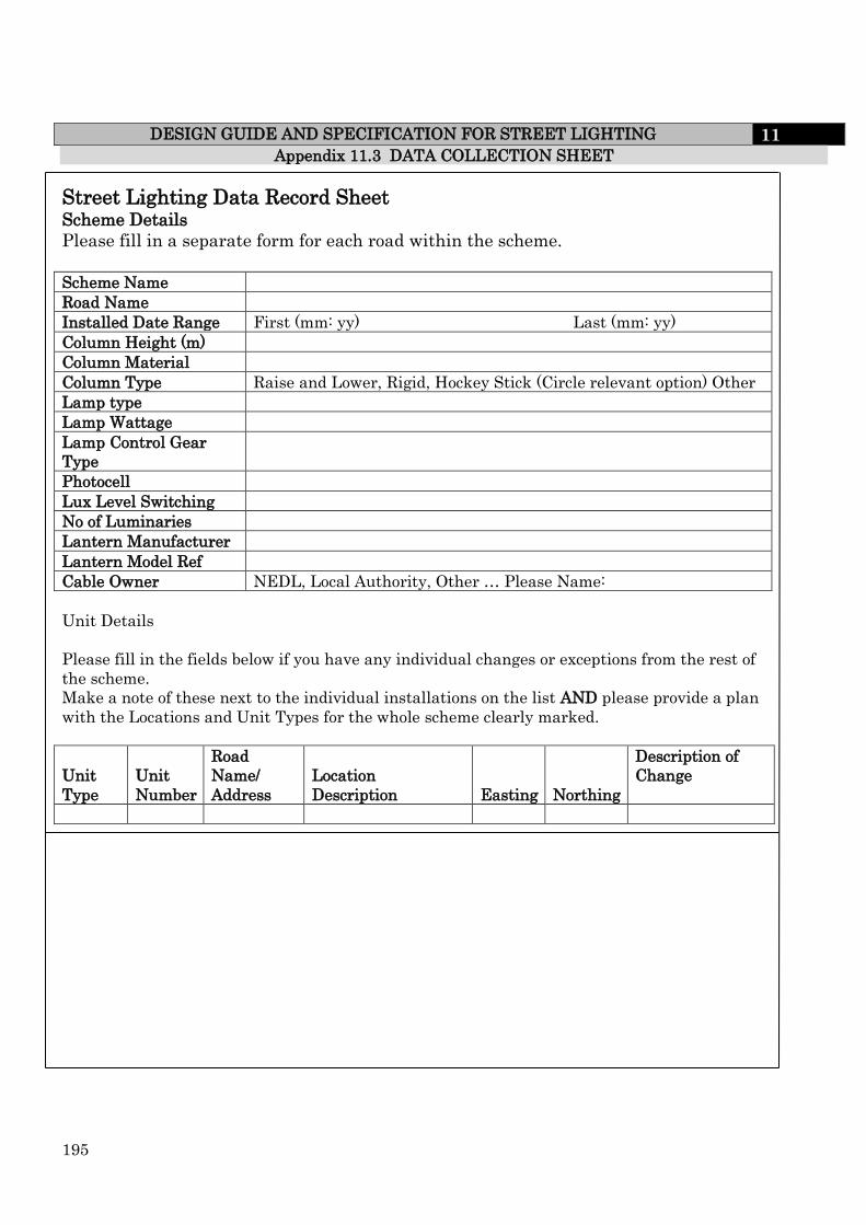
195
DESIGN GUIDE AND SPECIFICATION FOR STREET LIGHTING 11 Appendix 11.3 DATA COLLECTION SHEET
Street Lighting Data Record Sheet Scheme Details
Please fill in a separate form for each road within the scheme.
Scheme Name
Road Name
Installed Date Range First (mm: yy) Last (mm: yy)
Column Height (m)
Column Material
Column Type Raise and Lower, Rigid, Hockey Stick (Circle relevant option) Other
Lamp type
Lamp Wattage
Lamp Control Gear
Type
Photocell
Lux Level Switching
No of Luminaries
Lantern Manufacturer
Lantern Model Ref
Cable Owner NEDL, Local Authority, Other … Please Name:
Unit Details
Please fill in the fields below if you have any individual changes or exceptions from the rest of
the scheme.
Make a note of these next to the individual installations on the list AND please provide a plan
with the Locations and Unit Types for the whole scheme clearly marked.
Unit
Type
Unit
Number
Road
Name/
Address
Location
Description Easting Northing
Description of
Change

196
DESIGN GUIDE AND SPECIFICATION FOR STREET LIGHTING 11
PREFERRED ARRANGEMENT
PREFERRED ARRANGEMENT
SPEED HUMPS
10m
10m
Sketch No. 11.3.1 TYPICAL STREET LIGHTING LAYOUT WITH SPEED BUMPS
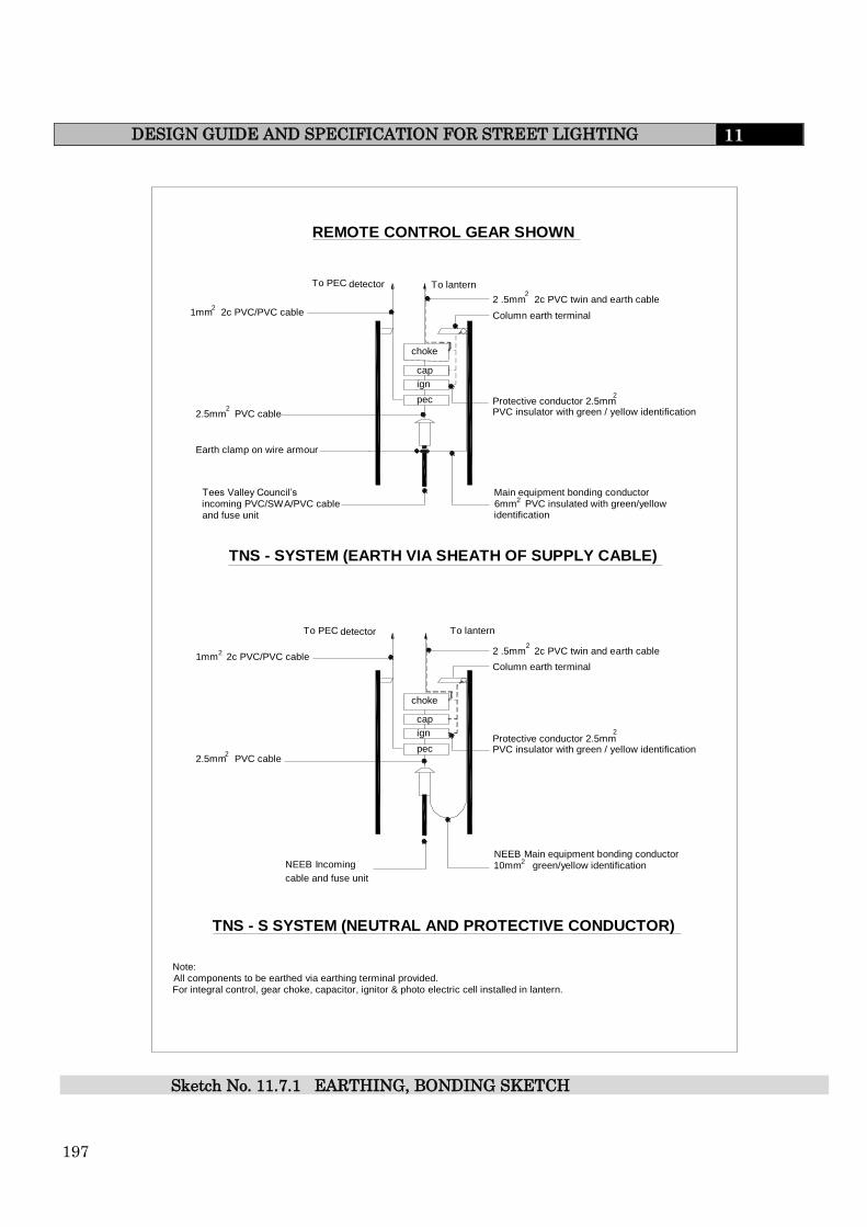
197
DESIGN GUIDE AND SPECIFICATION FOR STREET LIGHTING 11
choke cap ign pec
pec ign cap
choke
To PEC detector To lantern 2 .5mm 2c PVC twin and earth cable Column earth terminal
Protective conductor 2.5mm PVC insulator with green / yellow identification
Main equipment bonding conductor 6mm PVC insulated with green/yellow identification
Tees Valley Council’s incoming PVC/SWA/PVC cable and fuse unit
1mm 2c PVC/PVC cable
Earth clamp on wire armour
To PEC detector To lantern
2 .5mm 2c PVC twin and earth cable Column earth terminal
1mm 2c PVC/PVC cable
2.5mm PVC cable
2.5mm PVC cable
NEEB Incoming cable and fuse unit
Protective conductor 2.5mm PVC insulator with green / yellow identification
NEEB Main equipment bonding conductor 10mm green/yellow identification
2 2
2 2
2 2
2
2
2
2
Note: All components to be earthed via earthing terminal provided. For integral control, gear choke, capacitor, ignitor & photo electric cell installed in lantern.
REMOTE CONTROL GEAR SHOWN
TNS - SYSTEM (EARTH VIA SHEATH OF SUPPLY CABLE)
TNS - S SYSTEM (NEUTRAL AND PROTECTIVE CONDUCTOR)
Sketch No. 11.7.1 EARTHING, BONDING SKETCH

198
DESIGN GUIDE AND SPECIFICATION FOR STREET LIGHTING 11
FUSE CUT OUT DOUBLE POLE
COUNCIL
ELECTRIC FUSE CUT OUT
Electric Supply
Approved cable tag Black lettering on yellow background Tag should show N.E.
Sketch No 11.16.1 SUPPLY DETAILS

199
DESIGN GUIDE AND SPECIFICATION FOR STREET LIGHTING 11
Public Lighting Outgoing Supply
FUSE CUT OUT DOUBLE POLE
COUNCIL
ELECTRIC FUSE CUT OUT
Electric Supply
Approved cable tag Black lettering on yellow background Tag should show N.E.
Approved cable tag Black lettering on yellow background Tag should show column no. supplied
Sketch No. 11.17.1 SUPPLY USING ONE LOOP

200
DESIGN GUIDE AND SPECIFICATION FOR STREET LIGHTING 11
COUNCIL DOUBLE POLE FUSE CUT OUT
Approved cable tag Black lettering on yellow background Tag should show main feeder column no. M....................
Approved cable tag Black lettering on yellow background Tag should show feeder column no. F....................
Public Lighting Incoming Supply
Outgoing Supply Public Lighting
Sketch No. 11.17.2 PUBLIC LIGHTING SUPPLY (In and Out)
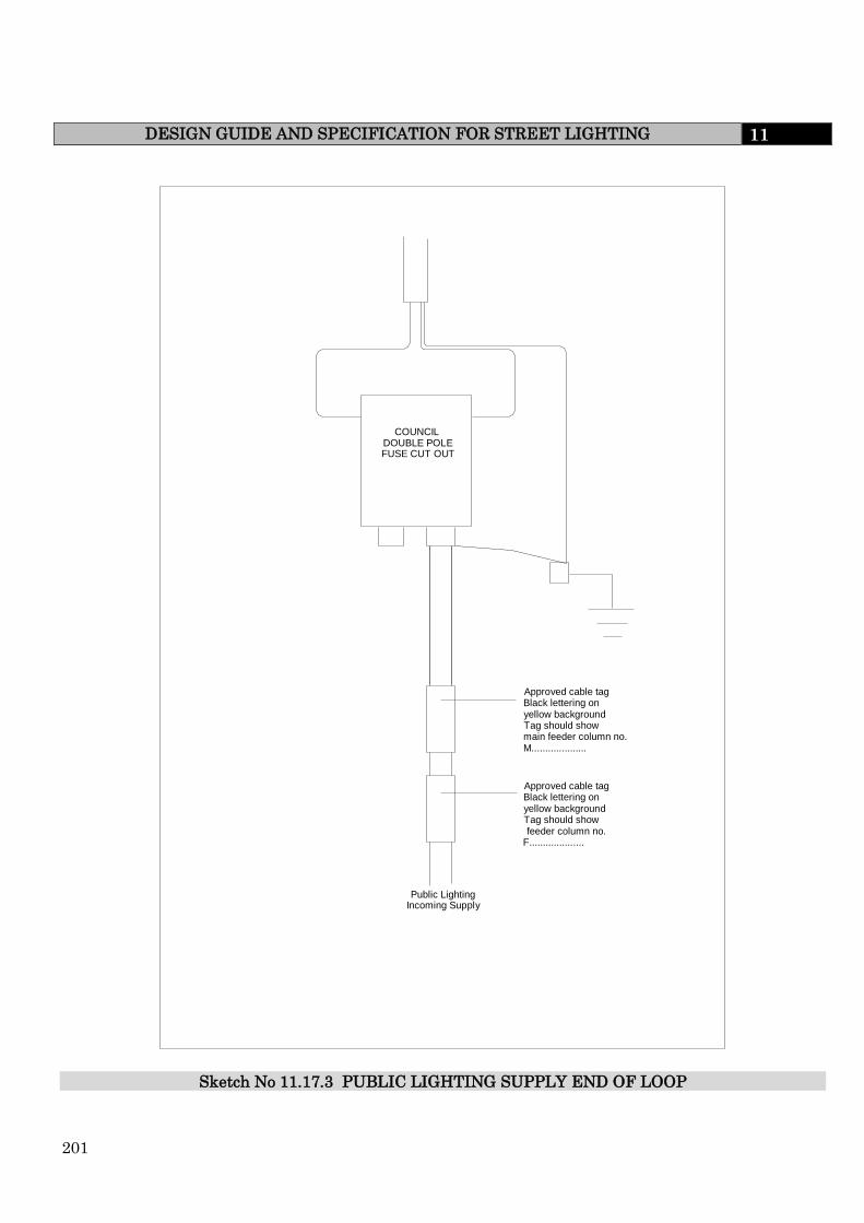
201
DESIGN GUIDE AND SPECIFICATION FOR STREET LIGHTING 11
COUNCIL DOUBLE POLE FUSE CUT OUT
Approved cable tag Black lettering on yellow background Tag should show main feeder column no. M....................
Approved cable tag Black lettering on yellow background Tag should show feeder column no. F....................
Public Lighting Incoming Supply
Sketch No 11.17.3 PUBLIC LIGHTING SUPPLY END OF LOOP

202
DESIGN GUIDE AND SPECIFICATION FOR HIGHWAY DRAINAGE 12
12.0 HIGHWAY DRAINAGE
12.1 INTRODUCTION
This section is to be used for the design and construction of highway drainage only.
The Highway Authority is responsible for the adoption of surface water systems serving
highway areas only. The highway drainage system will consist of those lengths where no
other drainage is being received, other than from adopted areas and where the Water
Authority has indicated that it is not prepared to adopt that system.
The design and construction of a drainage system should be fully in
accordance with the criteria set out in the Water Authorities Association
"Sewers for Adoption – A Design and Construction Guide for Developers"
current edition (except as amended by this document).
12.2 LOCATION OF HIGHWAY DRAINS
Highway drains shall be constructed within the limits of the highway.
Where there is a requirement that the drain is located outside the limits of the highway,
i.e. outfall to water courses (see also Clause 4.5 and 12.8), a 'Deed of Grant of Easement'
will be required. It is the responsibility of the Developer to obtain all such consents.
12.3 PIPES FOR DRAINAGE
Pipes for drainage shall be selected from the alternatives given in Table 12.3.1 and shall
comply with the specification requirements applicable to the pipe type selected.
TABLE 12.3.1
MATERIAL TYPE STANDARD
Vitrified clay
Concrete
Unplasticised polyvinyl-chloride
Plastics
BS 65
BS5911:Part 100
BS4660 or BS5481
BS4962
Minimum Pipe Size
The minimum pipe diameter for carriageway drainage shall be 150mm. For footpath,
footway or cycleway the minimum pipe diameter may be 100mm.
All site connections within the limits of the carriageway shall be a minimum of 150mm
diameter.
12.3 TRENCH EXCAVATION
All trenches shall be excavated in straight lines, to the correct levels and shall have vertical
trench walls.

203
DESIGN GUIDE AND SPECIFICATION FOR HIGHWAY DRAINAGE 12
If the pipe formation is damaged, through any cause, and is considered by the Engineer
to be unacceptable for the construction of the pipeline then the Developer shall, as
directed by the Engineer, remove the damaged formation and backfill with an approved
granular material.
Support to Utility's Apparatus
The Developer shall protect and support any utility's apparatus which pass over or under
the line of the drain and before the completion of the works restore them to their original
condition. All works shall be carried out to the satisfaction of the Engineer and to the
requirements of the Statutory Undertakers and the owners of the apparatus.
Tidal, Flowing, Ground Water and Standing Water
The Developer shall take measures and carry out any operations necessary for dealing
with tidal, flowing, ground water or standing water within the site.
A method statement detailing the measures and operations shall be submitted to the
Engineer.
Bedding and Laying of Pipelines and Backfilling of Trenches
Immediately following the excavation of the trench the pipes shall be laid and jointed on
the pipe bed. Pipes shall be laid so that each one is in contact with the bed throughout
the length of its barrel. In the case of socketed or sleeve jointed pipes the socket or sleeve
shall not bear directly on the bed. See sketch no. 12.4.1.
The pipes shall be laid to the design level and gradients.
Pipe bedding material shall be selected from the appropriate bedding given in Table
12.4.1.
Trenches shall be backfilled as soon as practicable after the drain has been laid. The
Developer shall give the Engineer reasonable notice (at least 24 hours) that the pipeline
is complete and ready for testing.
Drains shall have watertight joints and shall be tested as described in Clause 12.4.5.
Backfilling operations shall be as follows:-
(a) Area around and immediately above pipe (0mm to 300mm above crown of pipe)
The material shall be Type A consisting of crushed rock (excluding shale), crushed blast
furnace slag from a source approved by the Engineer or crushed concrete complying with
the grading requirements of Table 12.4.1.
The material shall be carefully placed and compacted using light compaction techniques
in layers not exceeding 150mm, from bedding level to 300mm above the crown of the
pipe.

204
DESIGN GUIDE AND SPECIFICATION FOR HIGHWAY DRAINAGE 12
NOTE: There are many methods of achieving light compaction and
therefore it is not the intention, nor indeed possible in this
document to give all acceptable combinations. The
compaction method adopted by the Developer should take
into account that light compaction immediately around
and above the pipe is essential to prevent damage to the
pipe.
(b) Area outside light compaction (300mm and above from crown of pipe)
In carriageways, the remaining depth of trench up to formation level shall be
backfilled with Type B material consisting of crushed rock (excluding shale), crushed
blast furnace slag (from a source approved by the Engineer) or crushed concrete.
The backfill shall be placed in layers not exceeding 150mm and compacted by
mechanical means.
NOTE: The Engineer may at any time carry out in situ density
tests on the compacted backfill to ensure that full
compaction has been achieved. This testing shall not
include light compaction areas.
If the in situ density test results indicate that compaction is inadequate then the
backfill shall be removed to a depth specified by the Engineer, replaced and
compacted as detailed above.
In footways, footpaths and cycleways backfilling operations shall comply with the
requirements of Clause 10.10.3.
In highway verges trenches may be backfilled with selected excavated materials,
subject to the approval of the Engineer.
When trench supports are employed, they shall be withdrawn in a safe manner not
more than 600mm in advance of the compacted backfilling operations. Any cavity
occurring during the withdrawal of trench supports shall be filled and compacted to
the satisfaction of the Engineer.
The Developer will be held responsible for any settlement which
occurs after backfilling operations have been completed and any
remedial action required by the Engineer until adopted by the
Highway Authority.

205
DESIGN GUIDE AND SPECIFICATION FOR HIGHWAY DRAINAGE 12
TABLE 12.4.1
NOMINAL SIZE OF
PIPE
MAXIMUM
PARTICLE SIZE
(mm)
SUITABLE IMPORTED GRANULAR
MATERIALS FOR BEDDING
100 10 10mm single size bedding
Over 100 to 150 14 10, 14 single size or 14 to 5mm graded
bedding
Over 150 to 300 20 10, 14 or 20mm single size or 14 to
5mm graded or 20 to 5mm graded
bedding
Over 600 40 14, 20 or 40mm single size or 14 to
5mm graded or 20 to 5mm graded or
40 to 5mm graded bedding
Testing Gravity Drains
Pipeline lengths shall be tested between manholes and shall comply with the
conditions given below. All drains shall be tested with air or water as directed by the
Engineer.
(i) Air Test
For the pipeline air test, air shall be pumped into the line by a suitable means
until a stable pressure of 100mm head of water has been achieved as indicated
in a U-tube connected to the system. The air pressure shall not fall to less than
75mm head of water during a period of 5 minutes without further pumping, after
an initial period to allow stabilisation. Drains with traps shall be tested to
50mm head of water and the permissible loss shall be not more than 14mm head
of water in 5 minutes after the initial stabilisation period.
(ii) Water Test
For the pipeline water test the pipes shall be filled with water under a head of
not less than 1.2m above the crown of the pipe at the high end and not more
than 6m above the pipe at the low end. Steeply graded pipelines shall be tested
in sections so that the above test conditions are met. Unless otherwise agreed by
the Engineer the test shall commence two hours after filling the test section.
The loss of water over a period of 30 minutes shall be measured by adding water
to the vertical feed pipe at regular 10 minute intervals to restore the original
water level. The amounts of water added at each interview shall be recorded.
The drain shall be deemed to have passed the test if the water added does not
exceed one litre per hour per linear meter of drain per metre of nominal internal
diameter.
Private Connections
Private connections, not forming part of the adoptable sewer system within the
highway limits, are the responsibility of the Developer and his successors but shall
be constructed in accordance with this specification.

206
DESIGN GUIDE AND SPECIFICATION FOR HIGHWAY DRAINAGE 12
12.4 MANHOLES
Construction of Manholes
Manholes shall be constructed in accordance with 'Sewers for Adoption'.
Precast Concrete Manholes
Precast concrete manhole rings shall comply with BS5911:Part 200.
Manhole Covers and Frames
Covers and frames for manholes shall be ductile iron complying with BS EN124 and shall
be painted with one coat of bituminous compound, to the approval of the Engineer.
Manholes greater than 1.2m deep shall have a minimum opening of 675mm x 675mm.
For manholes constructed in carriageways heavy duty double triangular covers and
frames (BS EN124 Class D400) shall be used. For manholes constructed in footways and
verges medium duty covers and frames (BS EN124 Class B125) shall be used.
Where manholes are located in areas of modular paving (block paving) the cover and
frame shall be of a type approved by the Engineer with inlaid blocks to match the
surrounding paving in block type, colour, texture and pattern.
Bricks
All bricks for engineering works associated with the highway drainage shall be clay Class
B Engineering bricks complying with the relevant provisions of BS 3921. The shapes and
dimensions of special bricks shall comply with the relevant provisions of BS4729.
Brickwork for Manholes
Brickwork for manholes shall be English bond and shall be laid on a full bed of mortar.
Single frogged bricks shall be laid frog up. Immediately after laying and for three days
thereafter the brickwork shall be protected against the harmful effects of weather.
Mortar
Cement shall be Portland Cement complying with BS12 or Sulphate Resisting Cement
complying with BS4027 where site conditions dictate resistance to sulphate attack is
required.
Sands shall comply with BS1199 and BS1200.
Water for mixing shall be potable water from the public water supply, for which the
Developer shall obtain the necessary consent of the Water Authority.
Water from any other source is not acceptable.
Mortar for brickwork shall be mixed in the proportions detailed in Table 12.5.1 below to
the mortar class required.
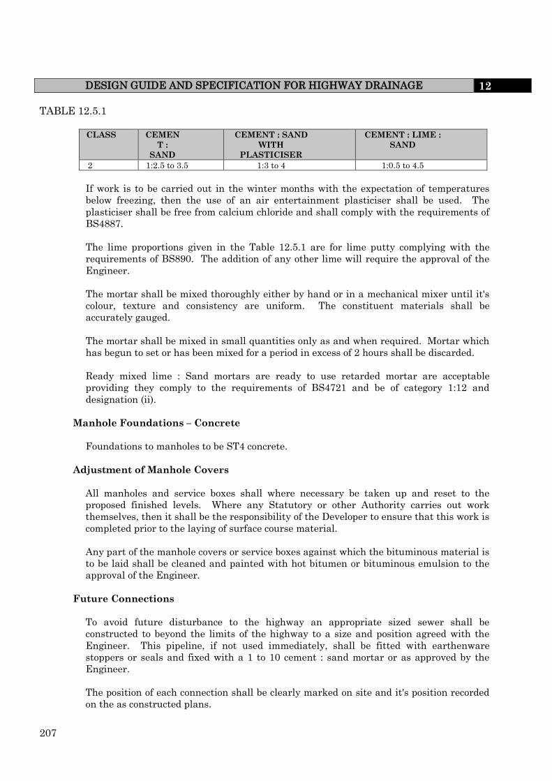
207
DESIGN GUIDE AND SPECIFICATION FOR HIGHWAY DRAINAGE 12
TABLE 12.5.1
CLASS CEMEN
T :
SAND
CEMENT : SAND
WITH
PLASTICISER
CEMENT : LIME :
SAND
2 1:2.5 to 3.5 1:3 to 4 1:0.5 to 4.5
If work is to be carried out in the winter months with the expectation of temperatures
below freezing, then the use of an air entertainment plasticiser shall be used. The
plasticiser shall be free from calcium chloride and shall comply with the requirements of
BS4887.
The lime proportions given in the Table 12.5.1 are for lime putty complying with the
requirements of BS890. The addition of any other lime will require the approval of the
Engineer.
The mortar shall be mixed thoroughly either by hand or in a mechanical mixer until it's
colour, texture and consistency are uniform. The constituent materials shall be
accurately gauged.
The mortar shall be mixed in small quantities only as and when required. Mortar which
has begun to set or has been mixed for a period in excess of 2 hours shall be discarded.
Ready mixed lime : Sand mortars are ready to use retarded mortar are acceptable
providing they comply to the requirements of BS4721 and be of category 1:12 and
designation (ii).
Manhole Foundations – Concrete
Foundations to manholes to be ST4 concrete.
Adjustment of Manhole Covers
All manholes and service boxes shall where necessary be taken up and reset to the
proposed finished levels. Where any Statutory or other Authority carries out work
themselves, then it shall be the responsibility of the Developer to ensure that this work is
completed prior to the laying of surface course material.
Any part of the manhole covers or service boxes against which the bituminous material is
to be laid shall be cleaned and painted with hot bitumen or bituminous emulsion to the
approval of the Engineer.
Future Connections
To avoid future disturbance to the highway an appropriate sized sewer shall be
constructed to beyond the limits of the highway to a size and position agreed with the
Engineer. This pipeline, if not used immediately, shall be fitted with earthenware
stoppers or seals and fixed with a 1 to 10 cement : sand mortar or as approved by the
Engineer.
The position of each connection shall be clearly marked on site and it's position recorded
on the as constructed plans.

208
DESIGN GUIDE AND SPECIFICATION FOR HIGHWAY DRAINAGE 12
12.6 CARRIAGEWAY GULLY CONNECTIONS
Connections from gullies to highway drains must be made with flexible jointed dense
vitrified clay pipes or UPVC pipes. The full length of the pipe shall be totally surrounded
with a 150mm thickness of Grade ST4 concrete incorporating flexible joints at no more
than 3m centres, see sketch no. 12.4.1.
Backfilling shall be in accordance with Clause 10.10.
Gully Spacing
For road gradients from 1.25% (1 in 80) to 0.67% (1 in 150) each gully shall drain an area
of carriageway and footpath, including highway verge, not exceeding 200m2.
Where gradients are in excess of 1.25% (1 in 80) the area shall not exceed 250m2.
The spacing of gullies for footpaths shall be agreed with the Engineer
Carriageway Gully Pots
Carriageway gully pots shall comply with the requirements of BS5911 : Parts 1-3 and be
manufactured from concrete with granite aggregate. They shall be 380mm internal
diameter and 780mm internal depth with 150mm diameter single seal trapped outlet and
cleaning eye complete with rodding eye and stopper, see sketch 12.6.1.
The gully pots shall be bedded on a foundation of 150mm of Grade ST4 concrete and be
surrounded with concrete of the same class for the full depth of the gully.
The surround shall in general be circular and 100mm minimum thickness but that part
of the rim or lip of the gully shall be cast rectangular on three sides to support the
brickwork under the gully frame and chamfered at 45 degrees into the circular surround.
In situ concrete gullies shall of the same internal dimensions as Precast and shall be
constructed of ST4 concrete of 150 mm minimum thickness, using permanent (plastic)
or removable shuttering. In situ gullies are not accepted by Stockton Council.
Where in situ concrete gullies are formed with permanent shuttering, such shuttering
shall have a current British Board of Agrément Roads and Bridges Certificate.
Procedure for construction.
Each gully should be installed in a suitably sized pit, allowing for a minimum
surround and base of 150 mm of concrete and any trench shoring required.
A concrete base at least 150 mm thick is laid.
The gully should be set level and in line with the branched drain, and haunched with
concrete up to its second rib.
The gully is surrounded, up to the lip, with a minimum of 150 mm of concrete. To
prevent distortion and flotation, the gully should be weighted by filling with water or
suitable ballast prior to placing the concrete. The concrete must be evenly distributed
and must fully surround the outlet spigot/ socket and connection joint; the use of a
vibrating poker will assist compaction and reduce void formation.

209
DESIGN GUIDE AND SPECIFICATION FOR HIGHWAY DRAINAGE 12
Carriageway Gully Grates and Frames
Gully grates and frames shall be of ductile iron and comply with the requirements of
BS EN124 (BS EN Class C325). They shall be painted with one coat of bituminous
compound.
The gully grate and frame is to be fitted with a theft resistance device and shall be set
with the hinge facing the direction of traffic flow and at such a level that the grate and
frame shall be set on two courses of 230mm brickwork (Class B), all mortar corbelled as
shown on sketch 12.6.1; the grating being 12mm below the finished surface level of the
channel.
Gullies shall be kept clean and free from debris during the course of the work and shall
be sealed with clean water as soon as construction is sufficiently advanced for them to
function.
At the end of the maintenance period and immediately before handing over the
completed work all gullies shall be thoroughly cleaned out and after inspection by the
Engineer resealed with water.
Footpath Gully Connections
Connections from gullies may be made with flexible jointed dense vitrified clay pipes or
externally ribbed UPVC pipes (complying with Sewers for Adoption). The full length of
the pipe shall be totally surrounded with 100mm thickness of Grade ST4 concrete with
flexible joints at no more than 3m centres.
Footpath Gully Pots
Footpath gully pots shall be 300mm diameter in accordance with BS539 : Table 24 and
shall be constructed in accordance with Clause 12.6.1.
Footpath Gully Grates and Frames
Footpath gully grates and frames shall be circular and hinges with a locking grid. They
shall comply with the general manufacturing requirements of BS EN124 and be a type
approved by the Engineer. They shall be manufactured in ductile iron to BS EN124 (BS
EN Class B125 – 325) and shall be set on a mortar bed.
Coating of Ironwork
If ironwork shows signs of rust at the end of the maintenance period it shall be wire-
brushed and re-coated with a bituminous compound/solution or replaced if considered
necessary by the Engineer.
12.7 EXISTING FIELD DRAINS
Where it is necessary for the Developer to cut through existing field drains steps must be
taken to carry the sub-soil water to it's outfall in as free a manner as before the
commencement of the works by reinstating with pipes of the same size and capacity as
the original.
When this is not possible the Developer may wish the agreement of the Engineer make a
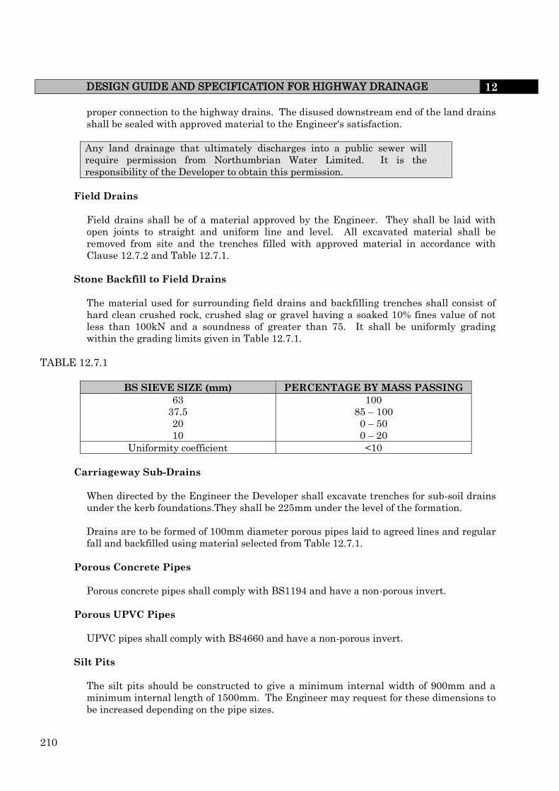
210
DESIGN GUIDE AND SPECIFICATION FOR HIGHWAY DRAINAGE 12
proper connection to the highway drains. The disused downstream end of the land drains
shall be sealed with approved material to the Engineer's satisfaction.
Any land drainage that ultimately discharges into a public sewer will
require permission from Northumbrian Water Limited. It is the
responsibility of the Developer to obtain this permission.
Field Drains
Field drains shall be of a material approved by the Engineer. They shall be laid with
open joints to straight and uniform line and level. All excavated material shall be
removed from site and the trenches filled with approved material in accordance with
Clause 12.7.2 and Table 12.7.1.
Stone Backfill to Field Drains
The material used for surrounding field drains and backfilling trenches shall consist of
hard clean crushed rock, crushed slag or gravel having a soaked 10% fines value of not
less than 100kN and a soundness of greater than 75. It shall be uniformly grading
within the grading limits given in Table 12.7.1.
TABLE 12.7.1
BS SIEVE SIZE (mm) PERCENTAGE BY MASS PASSING
63
37.5
20
10
100
85 – 100
0 – 50
0 – 20
Uniformity coefficient <10
Carriageway Sub-Drains
When directed by the Engineer the Developer shall excavate trenches for sub-soil drains
under the kerb foundations.They shall be 225mm under the level of the formation.
Drains are to be formed of 100mm diameter porous pipes laid to agreed lines and regular
fall and backfilled using material selected from Table 12.7.1.
Porous Concrete Pipes
Porous concrete pipes shall comply with BS1194 and have a non-porous invert.
Porous UPVC Pipes
UPVC pipes shall comply with BS4660 and have a non-porous invert.
Silt Pits
The silt pits should be constructed to give a minimum internal width of 900mm and a
minimum internal length of 1500mm. The Engineer may request for these dimensions to
be increased depending on the pipe sizes.

211
DESIGN GUIDE AND SPECIFICATION FOR HIGHWAY DRAINAGE 12
The walls shall be constructed of 225mm thick Class B Engineering brickwork set on
150mm thick Grade ST4 concrete foundation as detailed in sketch 12.7.1.
12.8 PROTECTION OF EXISTING WATERCOURSES
The Developer shall be responsible for maintaining watercourses within the development
in an effective working condition at all times.
If the Developer wishes to culvert any or all of an existing watercourses then they must
first gain the consent of the Lead Local Flood Authority for Ordinary Watercourses or
Environment Agency for Main River.
12.9 OUTFALL TO WATERCOURSES
The Developer's attention is drawn to the fact that if he intends to discharge highway
drainage into an existing beck or ditch then permission must be obtained from the
Environmental Agency or Lead Local Flood Authority depending on if the watercourse is
classified Critical ordinary watercourse or ordinary watercourse, prior to any discharge
taking place.
The Developer is responsible for obtaining all of the necessary permission and consent
requirements.
Sketch nos. 12.8.1 to 12.8.3 show various alternatives for outfall details.
12.10 CCTV SURVEY
The Developer must carry out a full colour CCTV survey of all drains and
connections. This shall be supported by a plan of the development indicating the
drains surveyed, together with a detailed report on the condition of the pipe
indicating the location of debris, faults and junctions. The information should be
made available to the Engineer and any remedial works necessary, carried out before
the surface course is laid to the carriageway.
12.11 OTHER STRUCTURES
A structure that is required to bridge a watercourse in order to construct a road will
be considered for adoption by the Highway Authority. Reference must be made to
"The Technical Approval Procedure for Developer's Structures", a copy of which can
be obtained from the Engineer.
12.12 OIL SEPARATORS
Surface water may be contaminated by oil at a number of different locations. To
prevent this happening Oil Separators are required in the following locations
car parks typically larger than 800m2 in area or for 50 or more car parking
spaces
smaller car parks discharging to a sensitive environment
areas where goods vehicles are parked or maneuvered
To be effective, oil separators need to be correctly designed, installed and maintained

212
DESIGN GUIDE AND SPECIFICATION FOR HIGHWAY DRAINAGE 12
Trapped gully pots can provide adequate protection for car parks that are too small
to justify the installation of a separator, but they must be properly maintained.
You might not need an oil separator if you use ‘sustainable drainage systems’
(SuDS). The SuDS approach should be used on all sites to minimise the impact of the
development on the environment. Techniques that control pollution close to the
source, such as permeable surfaces or infiltration trenches, can offer a suitable
means of treatment for run-off from low risk areas such car parks and non-
operational areas.
If an oil separator is required consideration as to where it will discharge must be
given. if you plan to discharge to surface water drains, to a watercourse or to the
ground, Environment Agency consent may be required.
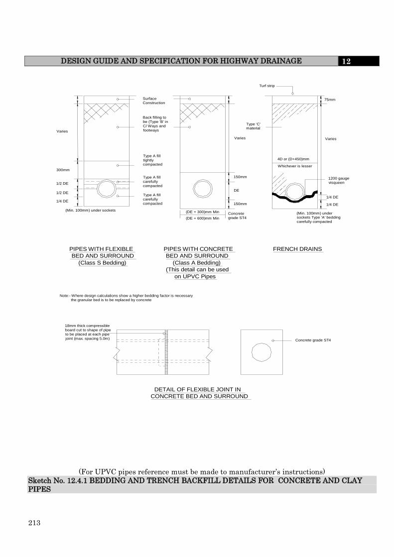
213
DESIGN GUIDE AND SPECIFICATION FOR HIGHWAY DRAINAGE 12
PIPES WITH FLEXIBLE BED AND SURROUND
(Class S Bedding)
PIPES WITH CONCRETE BED AND SURROUND
(Class A Bedding) (This detail can be used
on UPVC Pipes
FRENCH DRAINS
Note:- Where design calculations show a higher bedding factor is necessary the granular bed is to be replaced by concrete
18mm thick compressible board cut to shape of pipe to be placed at each pipe joint (max. spacing 5.0m) Concrete grade ST4
Varies
300mm
1/2 DE
1/2 DE 1/4 DE
(Min. 100mm) under sockets
Surface Construction
Back filling to be (Type 'B' in C/ Ways and footways
Type A fill tightly compacted
Type A fill carefully compacted
Type A fill carefully compacted
150mm
DE
150mm
Concrete grade ST4 (DE + 600)mm Min
(DE + 300)mm Min
4D or (D+450)mm Whichever is lesser
Varies
Turf strip
Type 'C' material
Varies
75mm
1/4 DE 1/4 DE
1200 gauge visqueen
(Min. 100mm) under sockets Type 'A' bedding carefully compacted
DETAIL OF FLEXIBLE JOINT IN CONCRETE BED AND SURROUND
(For UPVC pipes reference must be made to manufacturer’s instructions)
Sketch No. 12.4.1 BEDDING AND TRENCH BACKFILL DETAILS FOR CONCRETE AND CLAY
PIPES
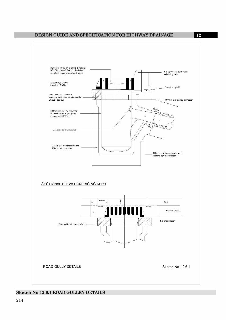
214
DESIGN GUIDE AND SPECIFICATION FOR HIGHWAY DRAINAGE 12
Sketch No 12.6.1 ROAD GULLEY DETAILS
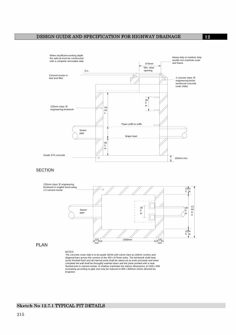
215
DESIGN GUIDE AND SPECIFICATION FOR HIGHWAY DRAINAGE 12
When insufficent working depth the split pit must be constructed with a complete removable slab.
Cement mortar in bed and fillet.
225mm class 'B' engineering brickwork
Grade ST4 concrete 150mm min
2 courses class 'B' engineering bricks reinforced concrete cover slabs.
Heavy duty or medium duty ductile iron manhole cover and frame
Pipes soffit to soffit
Water level
Sewer pipe
G.L.
675mm Min. clear opening
300mm Va
ries
600mm
SECTION
225mm class 'B' engineering brickwork in english bond using 1:3 cement mortar
Sewer pipe
PLAN
N NOTES The concrete cover slab is to be grade GEN4 with 12mm bars at 150mm centres and diagonal bars across the corners of the 450 x 675mm entry. The brickwork shall have joints finished flush and all internal joints shall be raked out as work proceeds and when complete the wall shall be throughly washed down and the joints pointed with a neat flushed joint in cement mortar. In shallow manholes the interior dimensions of 1500 x 900 increasing according to pipe size may be reduced to 900 x 600mm where directed by Engineer.
225 mm
1500mm 225 mm
225
mm
225
mm
300mm
300mm
1350mm
Sketch No 12.7.1 TYPICAL PIT DETAILS

216
DESIGN GUIDE AND SPECIFICATION FOR HIGHWAY DRAINAGE 12
ROCKER DETAILS ROCKER PIPE LENGTH
150 - 450 500 - 750
>750
PIPE DIAMETER 500 - 750 750 - 1000
SEEK GUIDANCE
A
Normal water level
Bed level
Stone pitching
50mm Pipe to protect beyond stone pitching
Headwall
Protective surround if required
Outfall pipe
Invert of pipe to be 225mm above normal water level and min. 225mm above apron
Pipelines shall have a flexible joint within 600mm of the front face of the headwall joining with a short "Rocker Pipe"
Minimum 75mm thick blinding concrete
500 gauge polythene sheeting
Toe to extend below hard bed level of watercourse
600mm
Profile to follow bank slope
SECTION TAKEN ON LINE A -A
GENERAL NOTES 1. The exact location of the outfall mustbe indicated. 2. Pipe outfall exit velocity should not exceed 1.2 m/s. 3. The headwall and wingwalls should not project beyond or above the line of the bank. 4. No part of the structure should cut into any flood embankment. 5. All surplus spoil from excavations for structure and pipe must be removed from site. 6. Stone pitching may be required to protect the bed and opposite bank downstream of the outfall. 7. The exact location of the outfall must be indicated. 8. Flap valve to be secured using a minimum of 4 bolts.
This dimension is dependant on normal water level
1000mm
600mm
200mm
Stone pitching on Class M1 motar
Direction of flow
Outfall to discharge approx. 45 to direction of flow
45
PLAN
Sketch No. 12.8.1 TYPICAL STORM WATER OUTFALL DETAIL TYPE 1

217
DESIGN GUIDE AND SPECIFICATION FOR HIGHWAY DRAINAGE 12
ROCKER DETAILS ROCKER PIPE LENGTH
150 - 450 500 - 750
>750
PIPE DIAMETER 500 - 750 750 - 1000
SEEK GUIDANCE
GENERAL NOTES 1. The exact location of the outfall mustbe indicated. 2. Pipe outfall exit velocity should not exceed 1.2 m/s. 3. The headwall and wingwalls should not project beyond or above the line of the bank. 4. No part of the structure should cut into any flood embankment. 5. All surplus spoil from excavations for structure and pipe must be removed from site. 6. Stone pitching may be required to protect the bed and opposite bank downstream of the outfall. 7. Flap valve to be secured using a minimum of 4 bolts.
Normal water level
Bed level
600mm
225mm
SECTION TAKEN ON LINE A - A
500 gauge polythene sheeting
Minimum 75mm thick blinding concrete
Outfall pipe
Protective surround if required
Pipe to protect beyond stone pitching 50mm
Stone pitching
Pipelines shall have a flexible joint within 600mm of the front face of the handwall joining with a short "Rocker Pipe"
Direction of flow
A
A
Stone pitching on class M1 mortar
Outfall to discharge approx. 45 degrees to direction of flow
PLAN
Sketch No. 12.8.2 TYPICAL STORM WATER OUTFALL DETAIL TYPE 2

218
GENERAL NOTES 1. The exact location of the outfall mustbe indicated. 2. Pipe outfall exit velocity should not exceed 1.2 m/s. 3. The headwall and wingwalls should not project beyond or above the line of the bank. 4. No part of the structure should cut into any flood embankment. 5. All surplus spoil from excavations for structure and pipe must be removed from site. 6. Stone pitching may be required to protect the bed and opposite bank downstream of the outfall.
Minimum 100mm thick concrete
255 to 300mm minimum size limestone pitching grouted in
Pipe to protect beyond stone pitching
Pipelines shall have a flexible joint within 600mm of the front face of the handwall joining with a short "Rocker Pipe"
Outfall pipe
Protective surround if required
500 gauge polythene sheeting
Minimum 75mm thick blinding concrete
Bed level
Normal water level
Headwall may be engineering brickwork or a precast concrete slab
ROCKER DETAILS ROCKER PIPE LENGTH
150 - 450 500 - 750
>750
PIPE DIAMETER 500 - 750 750 - 1000
SEEK GUIDANCE
A A
Direction of flow
600mm
25mm
SECTION TAKEN ON LINE A -A
PLAN
Sketch No 12.8.3 TYPICAL STORM WATER OUTFALL DETAIL TYPE 3
DESIGN GUIDE AND SPECIFICATION FOR HIGHWAY DRAINAGE 12

219
13.0 HIGHWAY VERGES AND LANDSCAPING
13.1 LANDSCAPING
For the purpose of this Design Guide and Specification ‘landscaping’ shall mean; all
hard landscaping including paving, means of enclosure and all soft landscaping
works including soiling, seeding, ground preparation, planting, protection and
maintenance of existing or proposed trees or shrubs.
13.2 AREAS FOR ADOPTION
Areas for adoption as Highway Verge by the Highway Authority should be clearly
defined on plans and where necessary separated from private gardens by edging kerbs,
or similar approved, set in the boundary at ground level.
Verges contiguous with front gardens, which provide for the accommodation of services
and lighting in “shared surfaces” will be adopted.
Similarly areas for consideration of adoption by the authority as public open space
should be clearly defined on plans. There is no guarantee that such areas will be
adopted although a clear indication as to the Authority’s position will be given as part of
the development control consultation process.
The Highway Authority will adopt verges contiguous with the carriageway and which
are provided in lieu of footways for the accommodation of statutory undertakers services
and public lighting. Such verges shall have a minimum width of 1.8m and where
necessary cater for the requirements of sight line visibility.
Hedges and fences will not normally be adopted as part of the public highway or public
open space and shall remain the responsibility of the adjacent landowners or
householders. This said existing hedgerows should not be lost within the confines of
new boundary fences but should remain part of the curtilage of the property as defined
on official deeds.
13.3 DESIGN REQUIREMENTS
This section consists of notes on the design of both soft and hard landscape elements
on highway verges, but planting principles and selection are considered in later
sections of this specification.
Soft landscape
Grass areas should not be less than 1m wide. Shrub areas where there are hard
surfaces on both sides should not be less than 2m wide to facilitate establishment.
Grass areas require a 2m (min.) wide access point to avoid having to use hand
mowing machines. They should lie 25mm (min.) above adjacent hard surfaces and
inspection chambers after soil settlement to avoid damage to grass cutting machines
DESIGN GUIDE AND SPECIFICATION FOR HIGHWAY VERGES AND
LANDSCAPING 13

220
DESIGN GUIDE AND SPECIFICATION FOR HIGHWAY VERGES AND
LANDSCAPING
13
Verges must be designed so that any surface water run off discharges to the highway
or onto an adoptable piped system. Where space allows consideration must be given
to the use of Sustainable Drainage (SuDs) to accommodate surface water drainage.
Footpaths should in general follow the line most people would wish to walk. Right-
angled corners on footpaths across grass areas should be avoided. Where new
pedestrian desire lines appear during the maintenance period the Developer shall
carry out all works found necessary to resolve problems as directed by the Engineer.
When designing sloping grass banks local standards for each council should be
checked and all work should be in accordance with BS 4428:1989 General Landscape
Operations Tops and toes of embankments should be rounded to facilitate mowing.
Hard landscape
Hard surfaces should be agreed with the Engineer prior to adoption. In town centres,
local centres, conservation areas and other high profile areas each council should be
consulted at an early stage in the design process to agree any particular preferences
(Style Guide) for material and bonding pattern. Where no particular style is given
then the use of high quality surface materials shall be considered.
13.4 PREPARATION OF FORMATION AND SOILING
Prior to any form of soft landscaping all of the areas must be cleared of bricks, hard-core
and any other debris over 50mm in dimension all of which shall be removed from site.
Any areas contaminated by fuel storage, concrete mixing etc. must be excavated and
backfilled with clean soil in accordance with appropriate specifications described below.
Clean subsoil should be used to form shapes indicated by contours on the landscape
drawings. The subsoil is to be spread in layers not more than 200mm thick. The areas
should then be broken up with a surface ripper to a 600mm depth with the tine spacing
set at 500mm centres and any further debris arising of 50mm diameter or greater
removed from site.
The areas should then be spread with approved topsoil from stock, providing it meets
the requirements of the current BS 3882, care being taken to avoid compaction. Using
the landscape drawings as a guide the following depths of approved topsoil should then
be provided.
(i) Shrub areas 450mm minimum
(ii) Grass areas 150mm minimum
(iii) Trees The depth will be dependent on the specification of the root
ball – the soil depth should accommodate the root spread of
a tree without compaction or contamination
Formation levels should be such that finished levels will be:-

221
DESIGN GUIDE AND SPECIFICATION FOR HIGHWAY VERGES AND
LANDSCAPING
13
(i) 30mm above level with paving or kerb levels, following settlement where seeding
or turfing is to occur.
(ii) Minimum 150mm below DPC of adjoining buildings.
(iii) Minimum 225mm below DPC of adjoining buildings when a mulch is to be
applied.
(iv) 75mm below paving or kerb levels and dished back from 0.5m where a mulch
is to be applied to shrub or tree planted areas.
NB: A hard surface strip should be placed adjacent to any building to facilitate
maintenance/window cleaning. This width will depend on the building height
to allow safe access.
13.5 EXISTING VEGETATION
Existing trees and hedges in particular can occupy a substantial part of a
development site and can have a major influence on layout design and use of the
site, especially if trees are protected by Tree Preservation Orders. It is often
necessary that great care is to be taken to preserve these trees, particularly when
changes to a street are planned as they are often very important site features giving
an area local distinction. Developments which are poorly designed in relation to
existing trees, or layouts retaining trees of an inappropriate size, species or
condition, can create pressure to prune or remove them in the future. To reduce such
problems, specialist advice is needed in the design process from a suitably qualified
Arborculturist.
British Standard 5837:2005 Trees in relation to Construction must be consulted
where trees already exist on a development site. Information required prior to
development includes:
a detailed survey plan indicating the position of all trees and proposed
developments, the canopy spreads of existing trees, and existing and proposed
levels. The trees to be retained or removed are to be clearly identified on
submitted plans;
a scheme of tree protection. A protective fence of an approved specification must
protect as a minimum the Root Protection Area of each tree which is to be
identified as the construction exclusion zone. Agreement to work within this
area will only be with agreement of the Engineer; site procedures and practice
must avoid problems such as soil compaction, changes in soil levels, changes in
the water table, root disturbance by excavation, spillage of chemicals, fire
damage, physical damage and the storage of materials in close proximity to
trees, all of which are not to be permitted and could lead to die back, death and
potential failure of existing trees with consequent Health and Safety issues and
legal liability.;

222
DESIGN GUIDE AND SPECIFICATION FOR HIGHWAY VERGES AND
LANDSCAPING
13
method statements for construction works and foundation design and the
provision of services and excavations to facilitate construction where approved,.
Where it is essential that ground services are routed within the root protection
area around the tree, the excavation must be carried out by hand, taking
precautions so as not to sever roots greater than 25mm diameter. Tree Roots
must not be left exposed to avoid the dangers of drying out or frost damage.
Services should under normal circumstances be routed directly under the centre
of a tree by tunnel boring to minimise damage. Reference must be made to the
‘Volume 4: NJUG Guidelines For the Planning, Installation And Maintenance
Of Utility Apparatus In Proximity To Trees (Issue 2) – Operatives
Handbook 19th November 2007 when trees are likely to be affected by services;
Full details of trees to be replanted as substitutes for those to be removed on
approval including, name, size, and planting and maintenance specifications.
13.6 DEMOLITIONS
Buildings, walls, roads, foundations, disused drains, manholes and any other
construction not needed should be demolished to minimum depths below finished
levels, as follows:-
(i) grass areas: 450mm
(ii) ground cover and perennial planting areas: 450mm
(iii) shrub planting areas: 600mm
(iv) tree planting (within the estimated root zone of the mature tree): 1.0m
All arisings should be removed from the site, unless specified for re use on site by
the Engineer. Regarding the depths given above, concrete slabs or other impervious
layers should be assessed for size and depth so that the Site Supervisor can decide
as to whether the slabs or layers should be broken up to facilitate free drainage, or
whether they should be removed from the site to obviate future drainage problems.
When sub soiling and drainage operations are to be carried out consideration should
be given to the need for demolition work to be carried out to lower levels, to ensure
that effective drainage operations are achievable.
13.7 SOILING
All soiling, sowing and planting shall be carried out in accordance with BS 4428.
Imported subsoil shall be of agricultural origin, or as agreed with the Engineer, and
shall be free from weeds, sticks, stones and other deleterious material. Clay subsoil and
heavy clay topsoil shall be deemed unacceptable. No soil shall be brought on site
without the prior inspection and approval of the Engineer and the Developer shall give
24 hours notice of his intention to import soil on to the site. The Developer shall be
required to provide evidence/proof of origin for any soil imported onto site.

223
DESIGN GUIDE AND SPECIFICATION FOR HIGHWAY VERGES AND
LANDSCAPING
13
13.8 TOPSOIL
Topsoil shall be good quality to BS 3882 2007 ‘Specification for topsoil and
requirements for use’, free from deleterious matter, and shall have been approved by
the Supervising Officer prior to delivery to site. It shall be fertile, with a humus and
fibre content and shall have a good crumb structure and shall not contain an
excessive amount of weed seed or roots of perennial weeds.
Topsoil and subsoil stored temporarily on site shall be conserved in heaps not more
than 1.5m high deposited by retreat. Topsoil and subsoil must be stored separately.
The Developer shall keep soil heaps free from contamination by weeds, other
materials or sources at all times.
Prior to spreading topsoil, the formation level shall be graded to the levels
indicating on the drawings. Grading shall take place in layers not exceeding 150mm
consolidated thickness. Soil shall only be served in dry conditions and when the soil
is not water logged. Only tracked vehicles shall be used to avoid unnecessary
compaction.
Final levels, after reasonable consolidation shall be 30mm above adjoining paving,
kerbs, manhole covers. Where shrub beds are proposed, however, topsoil levels shall
rake down to 75mm below finished paving levels to facilitate the spreading of 75mm
settled depth of specified mulch.
The Developer shall apply repeated applications of non-hazardous systemic
herbicide such as glyphosate to kill any emerging weeds prior to seeding, turfing or
planting, in accordance with the manufacturer’s instructions.
13.9 STREET FURNITURE AND MOWING STRIPS
Street furniture, manhole covers and service boxes or other approved hard surface
sited in verge areas must be surrounded with 300mm minimum by 100mm
thickness of Grade ST4 concrete, or other approved hard standing, mowing strip to
facilitate grass cutting operations except for street nameplates which must also
extend under the nameplate. A float or brush finish is required and finished level
should be 30mm below the ground level.
Wherever grass is sown next to a wall or fence a mowing strip consisting of 300mm
x 100mm thickness of grade ST4 concrete or similar approved paving material shall
be constructed against the wall or extending underneath the fence and at a finished
level 30mm below finished ground level.
224
DESIGN GUIDE AND SPECIFICATION FOR HIGHWAY VERGES AND
LANDSCAPING
13
13.10 CULTIVATION FOR GRASS SEEDING
Prior to adoption, general amenity grass areas should be well established, with no
hollows or ruts, and cut to a height less than 30mm.. All work to prepare the grass
area must conform to BS 4428 1989 ‘General Landscape Operations’.
The whole of the area to be grassed should be cultivated to relieve compaction and
to produce a fine surface tilth. Cultivation should never be carried out during wet
weather or when the soil is excessively wet or in any condition likely to cause
damage to the soil structure. During this operation, all surplus vegetable matter,
surface stones and any other extraneous material exceeding 50mm diameter is to be
collected and disposed of to a tip off site. During the seedbed cultivation a pre
seeding fertiliser approved by the Supervising Officer shall be worked into the
topsoil at a rate of 35 g/m2.or as recommended by the manufacturer.
Seed shall be evenly sown in 2 directions and lightly harrowed or hand raked into the
surface.
13.11 GRASS SEED
A suitable grass seed mixture approved by the Engineer and spread the rate of 35
g/m2 shall be used for:-
(i) Highway Verges, Traffic Islands, Central Reservations
(ii) Steep slopes and Embankments
Grass seed must be fresh and proof of origin, purity and germination potential must
be provided to the Engineer on request.
Wildflower Seed. Instead of grass seed on its own, a wild flora mix may be
appropriate on some sites. This may be suggested by the Supervising Officer with
advice from other officers, or may be put forward by the developer as an option for
discussion. The opportunities for appropriate management will have to be addressed
on these occasions.
13.12 FIRST CUT
The seeded areas shall be mown when the grass is 100mm high, reducing to 75mm
height. On completion of the first cut, the areas will be stone picked and all
extraneous matter exceeding 40mm diameter will be collected and carted away.
Any bare areas shall be lightly re-sown.
13.13 MAINTENANCE – GRASS AREAS
During the maintenance period the Developer shall be responsible for undertaking
with due care, and generally in accordance with BS 7370-3 1991 ‘Recommendations
for maintenance of amenity and traditional turf (other than sports turf)’ and BS 4428
‘General Landscape

225
DESIGN GUIDE AND SPECIFICATION FOR HIGHWAY VERGES AND
LANDSCAPING
13
Operations’, ie all operations required to ensure the establishment and maintenance of a
weed free sward.
Pernicious weeds shall be treated with suitable “new grass” selective weed killer
applied 12 weeks after seeding if the grass was sown in spring. Grass sown in the
autumn shall to be similarly treated at the end of May the following year.
During the growing season, further cuts shall be given at a maximum of 4 week
intervals prior to final adoption at 75mm height .
13.14 TURFING
Turf should be good quality meadow turf, complying with BS 3969, fibrous, well
rooted, mown and free from matted or dead grass and pernicious weeds. Turves
should be of rectangular shape and of uniform thickness. Unless otherwise agreed
by the Engineer it should have a minimum thickness of soil of 25mm and a width of
300mm.
Turfing should be carried out in accordance with BS 4428.
Turves should be delivered at appropriate intervals throughout the work so as to
avoid, as far as possible, stacking for long periods. No turf should be laid in
exceptionally dry, frosty or otherwise unsuitable conditions.
The turves should be laid on the prepared soil bed and firmed into position in
consecutive rows with broken joints, closely butted and to the correct levels. The
turf should be laid off planks working over and evenly firmed with wooden beaters,
the bottom of the beaters being frequently scraped clean of accumulated soil or mud.
Any inequalities in finished levels owing to variation in turf thickness or uneven
consolidation of soil should be adjusted by raking and/or packing fine soil under the
turf. The finished levels of the turf should conform to the levels indicated on
drawings allowing for final settlement. Turf abutting paving or kerbs should be
approximately 25mm above the adjacent hard surface after laying and beating
operations.
A top dressing of finely sifted loamy topsoil or fine peat substitute of 6mm depth
should be applied and well brushed in on completion of turf laying.
Turf edges to borders, beds and margins should be carefully trimmed square and
true to line and curve as detailed.
On completion of turfing all areas should be watered thoroughly to ensure
establishment and continued survival of the turf. The Developer will be
responsible for the replacement of any areas of failed turf at his own expense.
13.15 PLANTING
Planting should be designed by integrating it into the streetscape wherever possible.
Planting, particularly of street trees, help to soften the street scene while creating

226
DESIGN GUIDE AND SPECIFICATION FOR HIGHWAY VERGES AND
LANDSCAPING
13
visual interest, improving microclimate (reducing wind and giving shade for
example) and providing valuable habitats for wildlife, which is especially important
in urban areas. Planting can also be used to create buffer zones, visual barriers, or
landmarks and gateway features.
Where trees are to be used in a design, careful consideration must be given to the
choice of species, their location and how they are planted. Trench planting, irrigation
pipes and urban tree soils will all increase the chance of trees surviving and
establishing themselves successfully, thereby minimising maintenance and
replacement costs.
Consideration should also be given to the potential effect of planting on the
construction of footways and underground services; this is particularly so with tree
planting.. Tree roots can have a serious detrimental effect on carriageways, footways
and highway drainage; however this can be reduced with designed tree pits as
illustrated in the tree pit detail drawing and careful species choice, avoiding high
water demanding species
These proposals should be agreed with the adopting local or highway authority.
13.16 TREE AND SHRUB SELECTION
Detailed comments regarding the appropriate selection of trees and shrubs on
individual development sites will normally be given as part of the development
control process. Only selected species of trees will be permitted within the highway
verge and early consultation with the Engineer is essential. However, developers
are reminded that the landscape design and plant selection must take into account
the mature size and habit of trees and shrubs. They should be sited to allow them to
achieve reasonable maturity without having deleterious effects on their
surroundings, or vice versa. Full consideration should be taken for the plants
demands, its proximity to buildings and services, and the effects large plants may
have on buildings. The recommendations of BS 5837:2005 “Trees in relation to
construction” should generally be followed in all cases. The developer should obtain
specialist advice when drawing up planting proposals. The relevant councils should
be consulted as regards specific individual planting lists that may be available.
Appropriate plant species should be selected, for example to avoid vigorous
spreading shrubs which will give rise to maintenance problems, thorny plants
which will produce hazards for pedestrians on footpaths, or tree species in car parks
that drop sap or fruit. Bed areas should be mulched with an approved medium
grade forest bark to 75 mm depth to reduce maintenance costs and improve
appearance where required.
The edges of grass areas that border shrub beds should be set out to suit mowing
operations e.g. avoiding sharp changes of angle.
Beds should be kept free of all weeds, litter and deleterious material.
227
DESIGN GUIDE AND SPECIFICATION FOR HIGHWAY VERGES AND
LANDSCAPING
13
Prior to adoption, shrub beds should be well-established. Shrubs are to be pruned
back to the confines of the bed.
Native tree and shrub species, particularly those producing berries, are beneficial to
wildlife, and consideration should be given to planting these species in or on the
edge of highway verges; this is particularly important in rural and rural edge
locations.
When designing planting schemes, plans which indicate the locations of the
proposed street lights and CCTV cameras should be consulted.
Secured by Design Principles should be considered, particularly as regards
boundary planting and screening.
13.17 TREES
Reference should be made to the relevant council’s tree planting techniques during
the design of tree planting schemes. The use of root barriers should be used to grow
trees near hard surfaces including roads and footpaths.
Information on the location of underground services should be obtained from the
relevant statutory undertakers prior to any design work for a development.
The size, type and location of trees to be used shall be agreed with the Engineer and
be in accordance with the general principles of BS 5837; 2005 “Trees in Relation to
Construction”. All work and materials specified for the planting of trees shall,
where applicable, be carried out in accordance with:
BS 4428, 1989 General Landscape Operations, Section F and :G;
BS 3936, 2007Part 1, Nursery Stock (Trees and Shrubs) and Part 4; Nursery
Stock (Forest Trees) Part 5 Nursery Stock (Poplars and Willows)
BS 3998,1989 Recommendations for Tree work.
13.18 SHRUBS Including Grasses and Herbaceous Plants
Where shrubs are to be planted in existing beds or top soiled areas, the ground
shall be completely cleared of grass and weeds by approved methods.
Shrub areas shall be cultivated by hand or rotavator to depth of 400mm
incorporating tree planting compost and approved fertiliser at rates recommended
by manufacturer. Stones exceeding 50mm diameter, roots and any other
extraneous matter shall be collected and removed from the site.
Bare rooted shrubs shall have been undercut and, according to species, cut back to
250mm or trimmed to encourage bushiness. They shall be graded for size and this
should be stated on the approved plans. If pot grown or containerised shrubs are
used then the size of the container should be stated and also the height from
ground level. Density of planting shall be appropriate to the species, the size of

228
DESIGN GUIDE AND SPECIFICATION FOR HIGHWAY VERGES AND
LANDSCAPING
13
plant material and the site conditions. Advice will be given at the planning stage
as part of the development control process.
Consideration could be given to planting specimen shrubs of 7, 10 or 15 Litre
container size to give an immediate impact. In these instances planting densities can
be reduced.
Where container grown plants are indicated the plants shall have been established in
the containers long enough for substantial new growth to have been produced within
the container. A volume in litres must be shown on planting plans and the capacity
of container used must be at least that capacity.
Plants shall be obtained from approved nurseries, preferably located in the north of
England or in Scotland for best results, and should comply with the requirements of
BS 3936 2007 Part 1. Plants shall have been grown in the UK for at least one
growing season. For native planting, stock of local provenance should be used.
13.19 TREE AND SHRUB PLANTING
The Developer should note that no tree planting will be generally permitted within
the area 4m from the kerb edge of any road to be adopted. However where a root
barrier of the type and to a depth, to be approved by the Engineer, is provided, then
the distance may be reduced to an absolute minimum of 2m depending on the variety
of tree specified.
The root screen must extend at least 0.5m below the possible root depth from ground
level.
All work and materials specified in this section shall, where applicable, be carried
out in accordance with BS 4428, General Landscape Operations, Section 7 and 8; BS
3936, Part 1, Nursery Stock (Trees and Shrubs) and Part 4, Nursery stock (Forest
Trees) and BS 3998, Recommendations for Tree Work and BS 4043 Transplanting
Root Balled Trees.
It is advisable that bare root plants have their entire root system dipped in a
thoroughly mixed proprietary water retaining Polymer based Root Dip immediately
on lifting in the nursery, in accordance with manufacturers instructions.
All plant material is to be wrapped in black plastic bags (NB: the local authority
would advocate the use of black lined/white outer heavy duty plastic bags for the
transportation of stock) at the supply nurseries to ensure that there is no drying,
sweating or any damage in transit between the growing nursery and planting out.
Trees and shrubs shall be supplied with protection in accordance with the
recommendation of BS 3936. After delivery, if planting is not to be carried out
immediately, balled plants shall be placed ‘cheek-to-cheek’ and root balls covered
with straw, soil, sand or moist compost and Hessian sheets to prevent drying out.
Bare rooted plants must be ‘heeled in’ by placing the roots in a prepared trench and
covering them with soil or compost, which shall be watered in to avoid air pockets
229
DESIGN GUIDE AND SPECIFICATION FOR HIGHWAY VERGES AND
LANDSCAPING
13
round the roots. If for any reasons the surface of the roots becomes dry they shall be
rejected and replacement stock used. If planting is to be delayed for more than a
week, packaged plants shall be unpacked, the bundles opened up and each group of
plants ‘heeled in’ separately and clearly labelled.
Unless otherwise agreed by the Engineer, planting will take place during favourable
weather and soil conditions from the first week in November to the first week in
March. No planting operations shall take place when the ground is frost bound,
covered in snow, excessively wet or waterlogged or in excessively windy conditions.
13.20 BULBS
All work should be to BS 3936 1987. Information on bulb planting standards should
be obtained from the relevant councils prior to designing a site layout. Generally all
spring flowering bulbs planted in ornamental grassland must flower no later than the
end of April to prevent disruption to the grass-cutting programme.
Where contours and space allow, planting by machine method is recommended.
However, planting by hand, by first lifting the turf and planting the bulbs at required
depths beneath and replacing the turf afterwards, is still acceptable, especially on
embankments.
13.21 MAINTENANCE OF PLANTED AREAS AND TREES
During the maintenance period the Developer shall be responsible for undertaking
with due care, and generally in accordance with BS 3936 1987 ‘Nursery Stock’ and
BS 4428 1989 ‘General landscape operations’ all operations required to ensure the
establishment and maintenance of healthy and vigorous plants.
Following frost or strong winds the Developer shall inspect all plants and firm as
necessary and replace all damaged stakes and ties
Stakes and ties shall be checked monthly to ensure that they are functioning as
intended and replaced if necessary. During this check, the Developer shall ensure
that ties are tensioned correctly and that there is no bark chafing.
The Developer shall be responsible for keeping all shrub areas and tree stations to a
1m diameter entirely free of weeds during the maintenance period. Strimmers
should never be used around the base of trees because of the danger of bark damage
and corresponding tree deaths.
The Developer shall be responsible for watering all stock during the maintenance
period to ensure the establishment and continued survival of plant material. During
April/May following planting the Developer shall apply an approved fertiliser to all
planted areas at the rates as recommended by the manufacturer.
The Developer’s attention is drawn to the severe damage which is caused to the
bases and trunks of newly planted trees by grass cutting operations. Any such
230
DESIGN GUIDE AND SPECIFICATION FOR HIGHWAY VERGES AND
LANDSCAPING
13
damaged trees may be rejected on inspection and will lead to delays in adoption
until replacement trees are established.
13.22 ADOPTION PROCEDURE
Where areas are to be offered for adoption as public open space or as part of the
adopted highway then on completion, the Developer will carry out the following
operations before handover, it should be noted that the scheme shall have been
properly established following regular inspections and shall ensure:
that trees, shrubs or other vegetation is thriving: any dead or dying plants
(including those subject to vandalism) are replaced in accordance with the
original specification or, where significant grown has occurred on adjacent
vegetation, to a size equal to that vegetation;
that all shrub beds and tree stations are entirely free of weeds;
that all litter and other debris is removed from site;’
that all planted areas are topped up with mulch to 75m settled depth where
mulch has been specified;
that beds are edged up where bordering grassed areas;
that all stakes and ties are removed from trees unless otherwise agreed by the
Engineer.;
that all necessary pruning of all die back on trees and shrubs is undertaken;
that all agreed commuted lump sums are paid to the adopting authority;
that all plant material is healthy and disease free;
that a maintenance schedule and long term management plan is provided
13.23 SUPPLEMENTARY PLANNING DOCUMENTS AND DESIGN GUIDES
The developer should seek to obtain all relevant planning documents and design
guides specific to each council borough in regards to highway verges and landscaping
to assist with any development proposals.

231
DESIGN GUIDE AND SPECIFICATION FOR STREET NAMEPLATES AND
FURNITURE
14
14.0 STREET NAMEPLATES
14.1 GENERAL
Within 4 weeks of commencing work on site, the Developer must submit to the
Engineer 2 copies of the detailed site layout showing the proposed naming and
numbering for approval. When the scheme has been approved, the Developer must
supply to the Engineer a negative to a 1 to 1250 scale showing full details of the
street names and house numbers.
The Developer must supply and erect temporary nameplates to the satisfaction of the
Engineer, before the first dwelling is occupied. Permanent street nameplates are to
be provided and fixed by the Developer on completion of the works.
14.2 DESIGN
The design of the street nameplates must be in accordance with the requirements of
the Department for Transport "Traffic Signs Regulations and General Directions".
The Developer must submit design proposals to the Engineer for approval.
The background shall be a non-reflective white material with a 12mm black border.
The primary lettering shall be in upper case black Kindersley letter 89mm high or
MOT 100mm high.
Secondary lettering shall consist of:-
(a) additional street names in upper case black Kindersley letters 51mm high or
MOT 50mm high.
(b) additional lettering and numerals in lower case black Kindersley 51mm high or
MOT 50mm high.
(c) where required by the Engineer a street postcode shall be included with
Kindersley letters 20mm high located in the bottom right-hand corner.
Directional arrows and other symbols should be black and appropriately sized.
Where the road has no secondary access, a 'No Through Road' sign coloured red and
white on a blue background must be added to the nameplates at the junction with
the through road.
14.3 MANUFACTURE
The nameplates shall be manufactured so as to provide a complete unit comprising
sub-surface graphics with a bonded back plate. Sign frames shall be constructed
from mild steel and be formed into a solid backed rebated tray with a minimum
rebate depth of 12mm. The faceplate should be reverse printed clear polycarbonate
(or similar) with a reinforced glass fibre backing plate of 4mm thickness.

232
DESIGN GUIDE AND SPECIFICATION FOR STREET NAMEPLATES AND
FURNITURE
14
A minimum of one 25mm x 25mm box section stiffener will be attached to each tray
with additional stiffeners being provided to ensure a maximum clear spacing
between adjacent members of not more than 200mm and a maximum distance from
top and bottom edges of 50mm.
14.4 ERECTION
Location of all nameplates should be agreed on site before erection.
Wall-Mounted - The nameplate is to be drilled, plugged and secured with
tamperproof fixings. When erected below 2.5m the
nameplate is to be protected in an enamelled mild steel or
galvanised tray.
Freestanding - Nameplates may be set by the following methods:-
(a) Tubular steel posts 76mm O/D provided with a cap and
base plate. The posts should be set a minimum 450mm
below ground with a minimum 150mm of ST4 concrete
surround.
(b) Reconstituted plastic posts with tamperproof mechanical
fixings to form a fully composite structure, with ground
fixing as in (a) above.
(c) When fixed in a grass verge the concrete surround should be
as detailed in Clause 13.9.
14.5 FURNITURE
The quality of the environment created by new development needs to be sustained
long after the last property has been occupied. This requires good design and high-
quality construction, followed by good management and maintenance. Developers
are encouraged to consider the innovative use of materials, processes or techniques,
bearing whole-life costs in mind.
It is a necessity that all materials meet the following requirements:
easy to maintain;
safe for purpose;
durable;
sustainable (including the manufacturing process and energy use);
appropriate to the local character.
The developer is also required to provide the Highway Authority with a
comprehensive list of names and addresses of suppliers and details of the materials
used.

233
DESIGN GUIDE AND SPECIFICATION FOR STREET NAMEPLATES AND
FURNITURE
14
The Developer must also be aware that a commuted sum for the maintenance of
non-standard materials/furniture will be a requisite of the Highway Authority.
STREET FURNITURE.
In the design of any new highway or environmental improvement scheme, the
amount, choice and location of street furniture should be carefully considered.
At the outset of a project, any superfluous and redundant street furniture should be
identified and removed. The proposed new street furniture should be reduced to a
minimum by the use of well designed simple and unobtrusive elements of limited
design range.
Each council should be consulted at an early stage in the design process to agree any
particular preferences e.g Style Guides for product use. Ideally all street furniture
should be in a matched style.
To help maximise space, street furniture should ideally be arranged in line near the
kerb edge to keep an unobstructed passage for the convenient and comfortable
passage of pedestrians. This is particularly important for wheelchair users, people
with other mobility aids, and people with children and pushchairs.
Minimum clear width
the minimum obstacle-free width is 1.8m;
widths should increase to 3m at bus stops and in shopping centres;
in existing constricted circumstances the minimum width is 1.2m.
When historic street furniture is being restored or replicated, accuracy and
authenticity must be strictly observed.
Every opportunity should be made to reduce the need for additional posts. Lamp
columns in particular should be used to accommodate signs, following discussions
with the Street Lighting Engineer, bus lane enforcement cameras,
telecommunication equipment and CCTV cameras. Other posts should be designed
to incorporate more than one sign.
Guard railings
Guard railings should be kept to a minimum to avoid street clutter and maintenance
liability. Where barriers are necessary for example where accident statistics support
their introduction the choice of design shall reflect any local distinctiveness and
character, for example in conservation areas or town centres. Final locations shall
not impede designated cycle routes.
Bollards
Strengthened paving and parking enforcement provide the scope to significantly
reduce the use of bollards. Generally bollards should be limited to the following
circumstances:

234
DESIGN GUIDE AND SPECIFICATION FOR STREET NAMEPLATES AND
FURNITURE
14
on kerb build-outs on side road junctions where no more than two bollards
(i.e. one on each corner) should be erected. Where a sign is necessary this
should be used in place of a bollard;
at, or in close proximity to, a major road junction, in place of guardrails to
protect pedestrians from vehicles mounting the footway;
to prevent vehicle access onto land under private ownership or where there is
a road closure. Where more than four bollards are considered necessary, the
Engineer’s advice should be sought and other measures considered.
Seating
Opportunities should be provided for seating that can be integrated into the
overall streetscape design. Areas where seating is likely to attract anti-social
activity should be avoided.
The potential for vandalism is a significant consideration as is the ease with which
the seating can be maintained. The nature of fixings below seats and benches can
affect the ease of sweeping or cleaning. This should be a key consideration when
determining the type and positioning of seating.
Seating should be located:
where there is adequate space;
preferably where the seat back is unexposed e.g. against a wall;
in areas sheltered from the wind, preferably receiving some sun;
not too close to road traffic or in the middle of the footway.
Litter and dog bins
Bins should be:
to the local authorities’ standard (capacity, type, locking mechanism etc;
positioned along the kerb edge;
positioned at frequent intervals in busy areas and shopping centres,
Recycling bins
Where required, recycling bins should be located underground or if surface mounded
units are utilised they shall be carefully integrated into the street scene. The bins
shall be located behind the footway edge, for ease of collection. The colour and size of
the bin aperture must be consistent with international recycling conventions to
ensure continuing public recognition.
The location and design of bins needs to be discussed and agreed with relevant
services including Street Cleansing at the design stage. Issues such as location,
volume and maintenance issues need to be considered.
235
DESIGN GUIDE AND SPECIFICATION FOR STREET NAMEPLATES AND
FURNITURE
14
Shelters
Built structures can be particularly disruptive to the street scene. Careful design
and location is essential to reduce clutter, maintain views and minimise
maintenance issues. Site-specific designs may be better than off-the-peg solutions:
shelters should be positioned and designed to minimise damage, vandalism
and opportunities for anti-social behaviour;
maintenance of shelters should be considered to ensure structures are kept
clean, and in are in a good state of repair.
14.6 CLUTTER
Street furniture, signs, bins, bollards, utilities boxes, lighting and other items which
tend to accumulate on a footway can clutter the streetscape. Clutter is visually
intrusive and has adverse implications for many disabled people.
.
Examples of reducing the impact include:
locating service inspection boxes within buildings or boundary walls;
ensuring that household bins and recycling containers can be stored off the
footway, however on collection days they can be left out without blocking the
footway or presenting hazards to users
designing street furniture to be in keeping with its surroundings

236
List of Sketches
Sketch No. 5.2.1 PLACE V MOVEMENT................................................................................................................... 28
Sketch No. 5.4.1 TYPICAL EXAMPLE OF PEDESTRIAN CROSSING POINT ..................................................... 39
Sketch No. 5.4.2 STATUTORY UNDERTAKERS APPARATUS RECOMMENDED POSITIONS ....................... 40
Sketch No. 5.5.1 ILLUSTRATIVE JUNCTION LAYOUTS ...................................................................................... 42
TABLE 5.5.1 STOPPING DISTANCES ................................................................................................................ 44
Sketch No. 5.5.2 VISIBILITY AT JUNCTIONS ........................................................................................................ 45
Sketch No. 5.5.2A VISIBILITY AT JUNCTIONS ........................................................................................................ 46
Sketch No. 5.5.3 FORWARD VISIBILITY ................................................................................................................. 48
TABLE 5.5.2 CARRIAGEWAY LAYER and MATERIAL .................................................................................. 51
APPENDIX 5.5 RECOMMENDED HIGHWAY DESIGN STANDARDS FOR RESIDENTIAL
DEVELOPMENTS ......................................................................................................................................................... 53
Sketch No. 5.5.4 LAYOUT OF A BUS LAY-BY ........................................................................................................ 54
Sketch No. 5.5.5 VEHICLE TURNING AREAS FOR RESIDENTIAL ESTATES ................................................. 55
APPENDIX 6.2 HIGHWAY DESIGN STANDARDS FOR INDUSTRIAL DEVELOPMENTS ........................... 62
Sketch No 6.2.1 VEHICLE TURNING AREAS – INDUSTRIAL ESTATES ......................................................... 63
Sketch No 6.2.2 INDUSTRIAL ESTATE VEHICULAR ENTRANCE ................................................................... 64
Sketch No 7.1 PARKING DIMENSIONAL REQUIREMENTS ........................................................................... 78
Sketch No. 7.2 OFF STREET CAR PARK DISABLED BAYS .............................................................................. 88
Sketch No 8.2.1 SPEED CUSHION .......................................................................................................................... 96
Sketch No 8.3.1 FLAT TOP ROAD HUMP............................................................................................................... 97
Sketch No 8.3.2 ROUND TOP ROAD HUMPS ........................................................................................................ 98
Sketch No 8.3 1 HORIZONTAL TRAFFIC CALMING ......................................................................................... 100
Sketch No 8.3.4 CHICANE STAGGER LENGTHS ............................................................................................... 101
Sketch No. 8.3.5 OVERRUN AREAS FOR REDUCED RADII CORNERS .......................................................... 102
Sketch No 9.11.1 CYCLE TRACK PRIORITY CROSSING..................................................................................... 109
Sketch No. 9.11.2 CYCLE TRACK CROSSING BENDING OUT’ AT MINOR ROAD........................................... 111
Sketch No 9. 11.3 CYCLETRACK GIVEWAY CROSSING ...................................................................................... 113
Sketch No 9.11.4 CYCLE TRACK CROSSING WITH REFUGE ISLAND ............................................................ 115
Sketch No 9.11.5 ACCESS BARRIERS .................................................................................................................... 117
APPENDIX 10.1 SAMPLING AND TEST METHODS IN ACCORDANCE WITH UKAS .................................. 127
Sketch No 10.4.1 TYPICAL FOOTPATH/CYCLETRACK EDGE DETAIL ........................................................... 141
Sketch No 10.5.1 TYPICAL SERVICE DUCT DETAIL .......................................................................................... 144
Sketch No 10.6.1 TYPICAL REINFORCED CONCRETE LAY-BY DETAIL ........................................................ 153
Sketch No 10.6.2 TYPICAL REINFORCED CONCRETE LAY-BY JOINTING DETAILS .................................. 154
Sketch No 10.9.1 TYPICAL VEHICULAR FOOTWAY CROSSING DETAIL ....................................................... 177
Sketch No. 10.10.1 TYPICAL SECTIONS FOR TRENCH REINSTATEMENTS ................................................... 181
Appendix 11.1 TEST & INSPECTION CERTIFICATE –INTERNAL COLUMN/WIRING ET1 .................... 193
Appendix 11.2 TEST AND INSPECTION CERTIFICATE LIGHTING CABLE NETWORK ET2 ................. 194
Appendix 11.3 DATA COLLECTION SHEET ..................................................................................................... 195
Sketch No. 11.3.1 TYPICAL STREET LIGHTING LAYOUT WITH SPEED BUMPS .......................................... 196
Sketch No. 11.7.1 EARTHING, BONDING SKETCH .............................................................................................. 197
Sketch No 11.16.1S UPPLY DETAILS ...................................................................................................................... 198
Sketch No. 11.17.2 PUBLIC LIGHTING SUPPLY (In and Out) .............................................................................. 200
Sketch No 11.17.3 PUBLIC LIGHTING SUPPLY END OF LOOP ......................................................................... 201
Sketch No. 12.4.1 BEDDING AND TRENCH BACKFILL DETAILS FOR CONCRETE AND CLAY PIPES .... 213
Sketch No 12.7.1 TYPICAL PIT DETAILS .............................................................................................................. 215
Sketch No. 12.8.1 TYPICAL STORM WATER OUTFALL DETAIL TYPE 1 ......................................................... 216
Sketch No. 12.8.2 TYPICAL STORM WATER OUTFALL DETAIL TYPE 2 ........................................................ 217
Sketch No 12.8.3 TYPICAL STORM WATER OUTFALL DETAIL TYPE 3 ........................................................ 218