Embed Size (px)
Citation preview
J2X1-7673-05ENZ0(06)June 2014
Windows/Linux
FUJITSU SoftwareServerView Resource Orchestrator Cloud Edition V3.1.2
Design Guide
Preface
Purpose of This Document
This manual provides an outline of FUJITSU Software ServerView Resource Orchestrator Cloud Edition (hereinafter ResourceOrchestrator) and the design and preparations required for setup.
Intended Readers
This manual is written for system administrators who will use Resource Orchestrator to operate the infrastructure in private cloud or datacenter environments.When setting up systems, it is assumed that readers have the basic knowledge required to configure the servers, storage, network devices,and server virtualization software to be installed. Additionally, a basic understanding of directory services such as Active Directory andLDAP is necessary.
Structure of This Document
This manual is composed as follows:
Chapter 1 Documentation Road Map
Explains the documentation road map, and how to read it.
Chapter 2 Overview
Provides an overview of Resource Orchestrator.
Chapter 3 Flow of Resource Orchestrator Design and Preconfiguration
Explains the flow of design and pre-configuration for Resource Orchestrator.
Chapter 4 System Configuration Design
Explains points to keep in mind when setting up a Resource Orchestrator environment.
Chapter 5 Defining User Accounts
Explains the user accounts used in Resource Orchestrator.
Chapter 6 Defining Tenants and Resource Pools
Explains how to design tenants and resource pools.
Chapter 7 Defining High Availability and Disaster Recovery
High availability is realized by using the following functions.
Chapter 8 Defining and Configuring the Server Environment
Explains how to define and configure server environments.
Chapter 9 Defining and Configuring the Network Environment
Explains how to define and pre-configure the network environment.
Chapter 10 Deciding and Configuring the Storage Environment
Explains how to decide and configure the storage environment.
Chapter 11 Deciding and Configuring Server Virtualization Software
Explains how to decide and configure server virtualization software.
Chapter 12 Installing and Defining Single Sign-On
When installing Resource Orchestrator, a Single Sign-On environment can be configured. This section explains the necessarypreparations.
- i -
Chapter 13 Deciding and Configuring the Power Monitoring Environment
Explains how to decide and configure the power monitoring environment.
Appendix A Port List
Explains the ports used by Resource Orchestrator.
Appendix B HTTPS Communications
Explains the HTTPS communication protocol used by Resource Orchestrator and its security features.
Appendix C Hardware Configuration
Explains how to configure hardware.
Appendix D Preparations for Creating a Physical L-Server
Explains how to perform design and configuration when creating a physical L-Server.
Appendix E Preparations for Creating a Virtual L-Server
Explains how to perform design and configuration when creating a virtual L-Server.
Appendix F Preparing for Automatic Configuration and Operation of Network Devices
Explains how to prepare for automatic configuration of network devices and operation.
Appendix G Sample Script for Automatic Configuration and Operation of Network Devices
Explains the sample scripts provided with Resource Orchestrator for performing automatic configuration of network devices and otheroperations.
Appendix H Ethernet Fabric Devices
Explains the methods for managing Ethernet fabric devices.
Appendix I Auto-configuration and Operations of Network Devices Using Simple Configuration Mode
Explains automatic configuration and the operation of network devices in simple configuration mode.
Appendix J IPCOM VX Series Devices
Explains the methods for managing IPCOM VX series devices.
Appendix K Preparations for Using VDI Coordination
Explains how to perform design and configuration for using VDI coordination.
Document Conventions
The notation in this manual conforms to the following conventions.
- When there is different information for the different versions of Resource Orchestrator, it is indicated as follows:
[All Editions] Sections relevant for all editions
[Cloud Edition] Sections related to Cloud Edition
[Virtual Edition] Sections related to Virtual Edition
- When using Resource Orchestrator and the functions necessary differ due to the necessary basic software (OS), it is indicated asfollows:
[Windows Manager] Sections related to Windows manager
[Linux Manager] Sections related to Linux manager
[Windows] Sections related to Windows
[Linux] Sections related to Linux
[Solaris] Sections related to Solaris
- ii -
[VMware] Sections related to VMware
[Hyper-V] Sections related to Hyper-V
[Xen] Sections related to RHEL5-Xen
[KVM] Sections related to RHEL-KVM
[Solaris Zones] Sections related to Solaris zones
[OVM for x86 2.2] Sections related to Oracle VM Server for x86 2.2
[OVM for x86 3.2] Sections related to Oracle VM Server for x86 3.2
[OVM for SPARC] Sections related to Oracle VM Server for SPARC
[Citrix Xen] Sections related to Citrix XenServer
[Physical Servers] Sections related to physical servers
- Unless specified otherwise, the blade servers mentioned in this manual refer to PRIMERGY BX servers.
- Oracle Solaris may also be indicated as Solaris, Solaris Operating System, or Solaris OS.
- Oracle Solaris Zones may also be indicated as Solaris Containers or Solaris Container.
- Oracle VM Server for x86 may also be indicated as Oracle VM.
- In Resource Orchestrator, the following servers are referred to as SPARC Enterprise.
- SPARC Enterprise M3000/M4000/M5000/M8000/M9000
- SPARC Enterprise T5120/T5140/T5220/T5240/T5440
- In Resource Orchestrator, the following servers are referred to as SPARC M10.
- SPARC M10-1/M10-4/M10-4S
- Fujitsu M10 is the product name used for SPARC M10 when they are sold outside Japan.
- References and character strings or values requiring emphasis are indicated using double quotes ( " ).
- Window names, dialog names, menu names, and tab names are shown enclosed by brackets ( [ ] ).
- Button names are shown enclosed by angle brackets (< >) or square brackets ([ ]).
- The order of selecting menus is indicated using [ ]-[ ].
- Text to be entered by the user is indicated using bold text.
- Variables are indicated using italic text and underscores.
- The ellipses ("...") in menu names, indicating settings and operation window startup, are not shown.
- The ">" used in Windows is included in usage examples. When using Linux, read ">" as meaning "#".
- If using Windows 8 or Windows Server 2012, please note the following:Operations descriptions in this manual use examples assuming operating systems up to Windows 7 and Windows Server 2008 - ifusing this product with Windows 8 or Windows Server 2012, read instructions regarding the [Start] menu as if they were instructionsfor the [Apps] page.Display the [Apps] page by right-clicking in the [Start] screen, and then clicking on [All apps].
- When using Resource Orchestrator on Windows 8.1 and Windows Server 2012 R2, please note the following.When OS operations are explained in this manual, the examples assume OSs up to Windows 7 and Windows Server 2008. When usingResource Orchestrator on Windows 8.1 or Windows Server 2012 R2, take explanations regarding the [Start] menu as indicating the[Apps] screen.The [Apps] screen can be displayed by swiping the [Start] screen from bottom to top, or clicking the downward facing arrow on thelower-left of the [Start] screen.
- iii -

Menus in the ROR console
Operations on the ROR console can be performed using either the menu bar or pop-up menus.
By convention, procedures described in this manual only refer to pop-up menus.
Regarding Installation Folder Paths
The installation folder path may be given as C:\Fujitsu\ROR in this manual.
Replace it as shown below.
- When using Windows 64-bit (x64)
C:\Program Files (x86)\Resource Orchestrator
- When using Windows 32-bit (x86)
C:\Program Files\Resource Orchestrator
Command Examples
The paths used in command examples may be abbreviated. When using commands, execute them using the paths in the "Name" columnin the "Reference Guide (Command) VE" and the "Reference Guide (Command/XML) CE".
Web Site URLs
URLs provided as reference sources within the main text are correct as of June 2014.
Please understand that they are subject to change without notice.
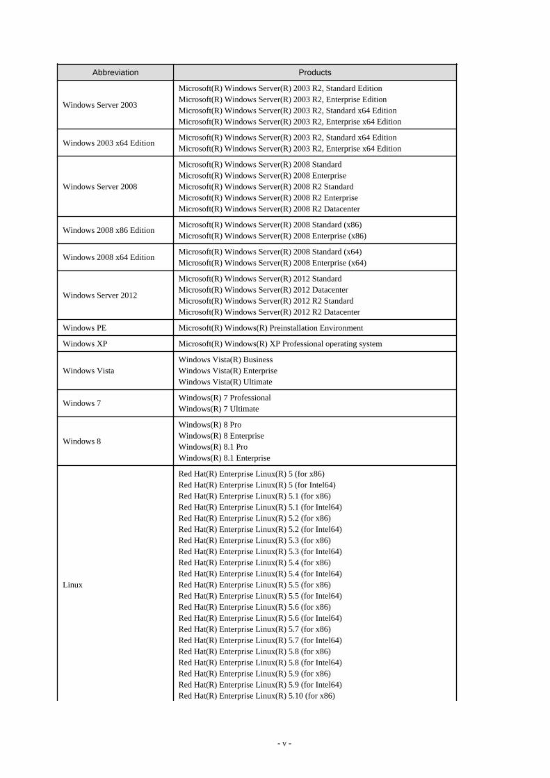
Abbreviations
The following abbreviations are used in this manual:
Abbreviation Products
Windows
Microsoft(R) Windows Server(R) 2003 R2, Standard EditionMicrosoft(R) Windows Server(R) 2003 R2, Enterprise EditionMicrosoft(R) Windows Server(R) 2003 R2, Standard x64 EditionMicrosoft(R) Windows Server(R) 2003 R2, Enterprise x64 EditionMicrosoft(R) Windows Server(R) 2008 StandardMicrosoft(R) Windows Server(R) 2008 EnterpriseMicrosoft(R) Windows Server(R) 2008 R2 StandardMicrosoft(R) Windows Server(R) 2008 R2 EnterpriseMicrosoft(R) Windows Server(R) 2008 R2 DatacenterMicrosoft(R) Windows Server(R) 2012 StandardMicrosoft(R) Windows Server(R) 2012 DatacenterMicrosoft(R) Windows Server(R) 2012 R2 StandardMicrosoft(R) Windows Server(R) 2012 R2 DatacenterMicrosoft(R) Windows(R) XP Professional operating systemWindows Vista(R) BusinessWindows Vista(R) EnterpriseWindows Vista(R) UltimateWindows(R) 7 ProfessionalWindows(R) 7 UltimateWindows(R) 8 ProWindows(R) 8 EnterpriseWindows(R) 8.1 ProWindows(R) 8.1 Enterprise
- iv -
Abbreviation Products
Windows Server 2003
Microsoft(R) Windows Server(R) 2003 R2, Standard EditionMicrosoft(R) Windows Server(R) 2003 R2, Enterprise EditionMicrosoft(R) Windows Server(R) 2003 R2, Standard x64 EditionMicrosoft(R) Windows Server(R) 2003 R2, Enterprise x64 Edition
Windows 2003 x64 EditionMicrosoft(R) Windows Server(R) 2003 R2, Standard x64 EditionMicrosoft(R) Windows Server(R) 2003 R2, Enterprise x64 Edition
Windows Server 2008
Microsoft(R) Windows Server(R) 2008 StandardMicrosoft(R) Windows Server(R) 2008 EnterpriseMicrosoft(R) Windows Server(R) 2008 R2 StandardMicrosoft(R) Windows Server(R) 2008 R2 EnterpriseMicrosoft(R) Windows Server(R) 2008 R2 Datacenter
Windows 2008 x86 EditionMicrosoft(R) Windows Server(R) 2008 Standard (x86)Microsoft(R) Windows Server(R) 2008 Enterprise (x86)
Windows 2008 x64 EditionMicrosoft(R) Windows Server(R) 2008 Standard (x64)Microsoft(R) Windows Server(R) 2008 Enterprise (x64)
Windows Server 2012
Microsoft(R) Windows Server(R) 2012 StandardMicrosoft(R) Windows Server(R) 2012 DatacenterMicrosoft(R) Windows Server(R) 2012 R2 StandardMicrosoft(R) Windows Server(R) 2012 R2 Datacenter
Windows PE Microsoft(R) Windows(R) Preinstallation Environment
Windows XP Microsoft(R) Windows(R) XP Professional operating system
Windows VistaWindows Vista(R) BusinessWindows Vista(R) EnterpriseWindows Vista(R) Ultimate
Windows 7Windows(R) 7 ProfessionalWindows(R) 7 Ultimate
Windows 8
Windows(R) 8 ProWindows(R) 8 EnterpriseWindows(R) 8.1 ProWindows(R) 8.1 Enterprise
Linux
Red Hat(R) Enterprise Linux(R) 5 (for x86)Red Hat(R) Enterprise Linux(R) 5 (for Intel64)Red Hat(R) Enterprise Linux(R) 5.1 (for x86)Red Hat(R) Enterprise Linux(R) 5.1 (for Intel64)Red Hat(R) Enterprise Linux(R) 5.2 (for x86)Red Hat(R) Enterprise Linux(R) 5.2 (for Intel64)Red Hat(R) Enterprise Linux(R) 5.3 (for x86)Red Hat(R) Enterprise Linux(R) 5.3 (for Intel64)Red Hat(R) Enterprise Linux(R) 5.4 (for x86)Red Hat(R) Enterprise Linux(R) 5.4 (for Intel64)Red Hat(R) Enterprise Linux(R) 5.5 (for x86)Red Hat(R) Enterprise Linux(R) 5.5 (for Intel64)Red Hat(R) Enterprise Linux(R) 5.6 (for x86)Red Hat(R) Enterprise Linux(R) 5.6 (for Intel64)Red Hat(R) Enterprise Linux(R) 5.7 (for x86)Red Hat(R) Enterprise Linux(R) 5.7 (for Intel64)Red Hat(R) Enterprise Linux(R) 5.8 (for x86)Red Hat(R) Enterprise Linux(R) 5.8 (for Intel64)Red Hat(R) Enterprise Linux(R) 5.9 (for x86)Red Hat(R) Enterprise Linux(R) 5.9 (for Intel64)Red Hat(R) Enterprise Linux(R) 5.10 (for x86)
- v -
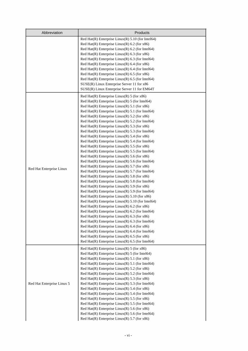
Abbreviation Products
Red Hat(R) Enterprise Linux(R) 5.10 (for Intel64)Red Hat(R) Enterprise Linux(R) 6.2 (for x86)Red Hat(R) Enterprise Linux(R) 6.2 (for Intel64)Red Hat(R) Enterprise Linux(R) 6.3 (for x86)Red Hat(R) Enterprise Linux(R) 6.3 (for Intel64)Red Hat(R) Enterprise Linux(R) 6.4 (for x86)Red Hat(R) Enterprise Linux(R) 6.4 (for Intel64)Red Hat(R) Enterprise Linux(R) 6.5 (for x86)Red Hat(R) Enterprise Linux(R) 6.5 (for Intel64)SUSE(R) Linux Enterprise Server 11 for x86SUSE(R) Linux Enterprise Server 11 for EM64T
Red Hat Enterprise Linux
Red Hat(R) Enterprise Linux(R) 5 (for x86)Red Hat(R) Enterprise Linux(R) 5 (for Intel64)Red Hat(R) Enterprise Linux(R) 5.1 (for x86)Red Hat(R) Enterprise Linux(R) 5.1 (for Intel64)Red Hat(R) Enterprise Linux(R) 5.2 (for x86)Red Hat(R) Enterprise Linux(R) 5.2 (for Intel64)Red Hat(R) Enterprise Linux(R) 5.3 (for x86)Red Hat(R) Enterprise Linux(R) 5.3 (for Intel64)Red Hat(R) Enterprise Linux(R) 5.4 (for x86)Red Hat(R) Enterprise Linux(R) 5.4 (for Intel64)Red Hat(R) Enterprise Linux(R) 5.5 (for x86)Red Hat(R) Enterprise Linux(R) 5.5 (for Intel64)Red Hat(R) Enterprise Linux(R) 5.6 (for x86)Red Hat(R) Enterprise Linux(R) 5.6 (for Intel64)Red Hat(R) Enterprise Linux(R) 5.7 (for x86)Red Hat(R) Enterprise Linux(R) 5.7 (for Intel64)Red Hat(R) Enterprise Linux(R) 5.8 (for x86)Red Hat(R) Enterprise Linux(R) 5.8 (for Intel64)Red Hat(R) Enterprise Linux(R) 5.9 (for x86)Red Hat(R) Enterprise Linux(R) 5.9 (for Intel64)Red Hat(R) Enterprise Linux(R) 5.10 (for x86)Red Hat(R) Enterprise Linux(R) 5.10 (for Intel64)Red Hat(R) Enterprise Linux(R) 6.2 (for x86)Red Hat(R) Enterprise Linux(R) 6.2 (for Intel64)Red Hat(R) Enterprise Linux(R) 6.3 (for x86)Red Hat(R) Enterprise Linux(R) 6.3 (for Intel64)Red Hat(R) Enterprise Linux(R) 6.4 (for x86)Red Hat(R) Enterprise Linux(R) 6.4 (for Intel64)Red Hat(R) Enterprise Linux(R) 6.5 (for x86)Red Hat(R) Enterprise Linux(R) 6.5 (for Intel64)
Red Hat Enterprise Linux 5
Red Hat(R) Enterprise Linux(R) 5 (for x86)Red Hat(R) Enterprise Linux(R) 5 (for Intel64)Red Hat(R) Enterprise Linux(R) 5.1 (for x86)Red Hat(R) Enterprise Linux(R) 5.1 (for Intel64)Red Hat(R) Enterprise Linux(R) 5.2 (for x86)Red Hat(R) Enterprise Linux(R) 5.2 (for Intel64)Red Hat(R) Enterprise Linux(R) 5.3 (for x86)Red Hat(R) Enterprise Linux(R) 5.3 (for Intel64)Red Hat(R) Enterprise Linux(R) 5.4 (for x86)Red Hat(R) Enterprise Linux(R) 5.4 (for Intel64)Red Hat(R) Enterprise Linux(R) 5.5 (for x86)Red Hat(R) Enterprise Linux(R) 5.5 (for Intel64)Red Hat(R) Enterprise Linux(R) 5.6 (for x86)Red Hat(R) Enterprise Linux(R) 5.6 (for Intel64)Red Hat(R) Enterprise Linux(R) 5.7 (for x86)
- vi -
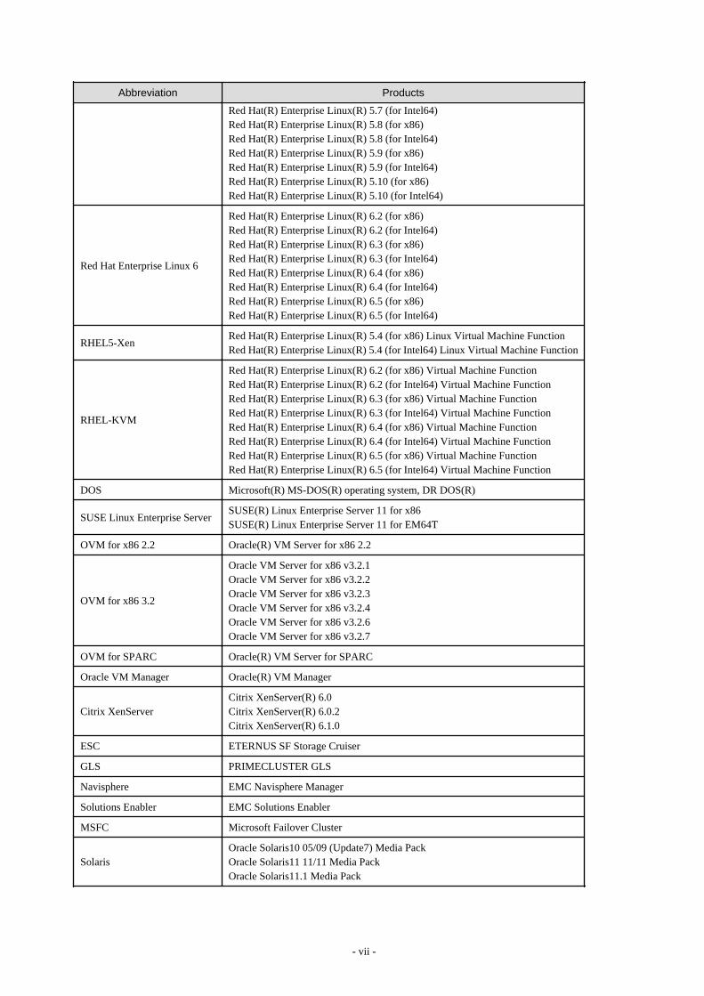
Abbreviation Products
Red Hat(R) Enterprise Linux(R) 5.7 (for Intel64)Red Hat(R) Enterprise Linux(R) 5.8 (for x86)Red Hat(R) Enterprise Linux(R) 5.8 (for Intel64)Red Hat(R) Enterprise Linux(R) 5.9 (for x86)Red Hat(R) Enterprise Linux(R) 5.9 (for Intel64)Red Hat(R) Enterprise Linux(R) 5.10 (for x86)Red Hat(R) Enterprise Linux(R) 5.10 (for Intel64)
Red Hat Enterprise Linux 6
Red Hat(R) Enterprise Linux(R) 6.2 (for x86)Red Hat(R) Enterprise Linux(R) 6.2 (for Intel64)Red Hat(R) Enterprise Linux(R) 6.3 (for x86)Red Hat(R) Enterprise Linux(R) 6.3 (for Intel64)Red Hat(R) Enterprise Linux(R) 6.4 (for x86)Red Hat(R) Enterprise Linux(R) 6.4 (for Intel64)Red Hat(R) Enterprise Linux(R) 6.5 (for x86)Red Hat(R) Enterprise Linux(R) 6.5 (for Intel64)
RHEL5-XenRed Hat(R) Enterprise Linux(R) 5.4 (for x86) Linux Virtual Machine FunctionRed Hat(R) Enterprise Linux(R) 5.4 (for Intel64) Linux Virtual Machine Function
RHEL-KVM
Red Hat(R) Enterprise Linux(R) 6.2 (for x86) Virtual Machine FunctionRed Hat(R) Enterprise Linux(R) 6.2 (for Intel64) Virtual Machine FunctionRed Hat(R) Enterprise Linux(R) 6.3 (for x86) Virtual Machine FunctionRed Hat(R) Enterprise Linux(R) 6.3 (for Intel64) Virtual Machine FunctionRed Hat(R) Enterprise Linux(R) 6.4 (for x86) Virtual Machine FunctionRed Hat(R) Enterprise Linux(R) 6.4 (for Intel64) Virtual Machine FunctionRed Hat(R) Enterprise Linux(R) 6.5 (for x86) Virtual Machine FunctionRed Hat(R) Enterprise Linux(R) 6.5 (for Intel64) Virtual Machine Function
DOS Microsoft(R) MS-DOS(R) operating system, DR DOS(R)
SUSE Linux Enterprise ServerSUSE(R) Linux Enterprise Server 11 for x86SUSE(R) Linux Enterprise Server 11 for EM64T
OVM for x86 2.2 Oracle(R) VM Server for x86 2.2
OVM for x86 3.2
Oracle VM Server for x86 v3.2.1Oracle VM Server for x86 v3.2.2Oracle VM Server for x86 v3.2.3Oracle VM Server for x86 v3.2.4Oracle VM Server for x86 v3.2.6Oracle VM Server for x86 v3.2.7
OVM for SPARC Oracle(R) VM Server for SPARC
Oracle VM Manager Oracle(R) VM Manager
Citrix XenServerCitrix XenServer(R) 6.0Citrix XenServer(R) 6.0.2Citrix XenServer(R) 6.1.0
ESC ETERNUS SF Storage Cruiser
GLS PRIMECLUSTER GLS
Navisphere EMC Navisphere Manager
Solutions Enabler EMC Solutions Enabler
MSFC Microsoft Failover Cluster
SolarisOracle Solaris10 05/09 (Update7) Media PackOracle Solaris11 11/11 Media PackOracle Solaris11.1 Media Pack
- vii -
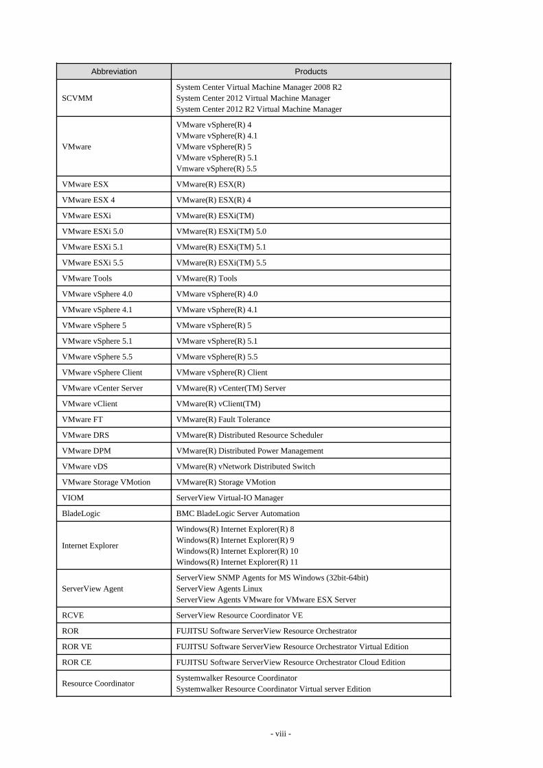
Abbreviation Products
SCVMMSystem Center Virtual Machine Manager 2008 R2System Center 2012 Virtual Machine ManagerSystem Center 2012 R2 Virtual Machine Manager
VMware
VMware vSphere(R) 4VMware vSphere(R) 4.1VMware vSphere(R) 5VMware vSphere(R) 5.1Vmware vSphere(R) 5.5
VMware ESX VMware(R) ESX(R)
VMware ESX 4 VMware(R) ESX(R) 4
VMware ESXi VMware(R) ESXi(TM)
VMware ESXi 5.0 VMware(R) ESXi(TM) 5.0
VMware ESXi 5.1 VMware(R) ESXi(TM) 5.1
VMware ESXi 5.5 VMware(R) ESXi(TM) 5.5
VMware Tools VMware(R) Tools
VMware vSphere 4.0 VMware vSphere(R) 4.0
VMware vSphere 4.1 VMware vSphere(R) 4.1
VMware vSphere 5 VMware vSphere(R) 5
VMware vSphere 5.1 VMware vSphere(R) 5.1
VMware vSphere 5.5 VMware vSphere(R) 5.5
VMware vSphere Client VMware vSphere(R) Client
VMware vCenter Server VMware(R) vCenter(TM) Server
VMware vClient VMware(R) vClient(TM)
VMware FT VMware(R) Fault Tolerance
VMware DRS VMware(R) Distributed Resource Scheduler
VMware DPM VMware(R) Distributed Power Management
VMware vDS VMware(R) vNetwork Distributed Switch
VMware Storage VMotion VMware(R) Storage VMotion
VIOM ServerView Virtual-IO Manager
BladeLogic BMC BladeLogic Server Automation
Internet Explorer
Windows(R) Internet Explorer(R) 8Windows(R) Internet Explorer(R) 9Windows(R) Internet Explorer(R) 10Windows(R) Internet Explorer(R) 11
ServerView AgentServerView SNMP Agents for MS Windows (32bit-64bit)ServerView Agents LinuxServerView Agents VMware for VMware ESX Server
RCVE ServerView Resource Coordinator VE
ROR FUJITSU Software ServerView Resource Orchestrator
ROR VE FUJITSU Software ServerView Resource Orchestrator Virtual Edition
ROR CE FUJITSU Software ServerView Resource Orchestrator Cloud Edition
Resource CoordinatorSystemwalker Resource CoordinatorSystemwalker Resource Coordinator Virtual server Edition
- viii -
Abbreviation Products
SVFAB ServerView Fabric Manager
Export Controls
Exportation/release of this document may require necessary procedures in accordance with the regulations of your resident countryand/or US export control laws.
Trademark Information
- BMC, BMC Software, and the BMC Software logo are the exclusive properties of BMC Software, Inc., are registered with the U.S.Patent and Trademark Office, and may be registered or pending registration in other countries.
- Citrix(R), Citrix XenServer(R), Citrix Essentials(TM), and Citrix StorageLink(TM) are trademarks of Citrix Systems, Inc. and/or oneof its subsidiaries, and may be registered in the United States Patent and Trademark Office and in other countries.
- EMC, EMC2, CLARiiON, VNX, Symmetrix, and Navisphere are trademarks or registered trademarks of EMC Corporation.
- HP is a registered trademark of Hewlett-Packard Company.
- Linux is a trademark or registered trademark of Linus Torvalds in the United States and other countries.
- Microsoft, Windows, MS-DOS, Windows Server, Windows Vista, Excel, Active Directory, and Internet Explorer are either registeredtrademarks or trademarks of Microsoft Corporation in the United States and other countries.
- Firefox is a registered trademark or trademark of Mozilla Foundation in the United States and/or other countries.
- NetApp is a registered trademark of Network Appliance, Inc. in the US and other countries. Data ONTAP, Network Appliance, andSnapshot are trademarks of Network Appliance, Inc. in the US and other countries.
- Oracle and Java are registered trademarks of Oracle and/or its affiliates in the United States and other countries.
- Oracle is a registered trademark of Oracle Corporation and/or its affiliates.
- Red Hat, RPM and all Red Hat-based trademarks and logos are trademarks or registered trademarks of Red Hat, Inc. in the UnitedStates and other countries.
- SUSE is a registered trademark of SUSE LINUX AG, a Novell business.
- VMware, the VMware "boxes" logo and design, Virtual SMP, and VMotion are registered trademarks or trademarks of VMware, Inc.in the United States and/or other jurisdictions.
- ServerView and Systemwalker are registered trademarks of FUJITSU LIMITED.
- All other brand and product names are trademarks or registered trademarks of their respective owners.
Notices
- The contents of this manual shall not be reproduced without express written permission from FUJITSU LIMITED.
- The contents of this manual are subject to change without notice.
Issue Date and Version
Month/Year Issued, Edition Manual Code
July 2012, First Edition J2X1-7673-01ENZ0(00)
October 2012, Second Edition J2X1-7673-02ENZ0(00)
December 2012, Third Edition J2X1-7673-03ENZ0(00)
- ix -
Month/Year Issued, Edition Manual Code
January 2013, Fourth Edition J2X1-7673-04ENZ0(00)
January 2013, Edition 4.1 J2X1-7673-04ENZ0(01)
January 2013, Edition 4.2 J2X1-7673-04ENZ0(02)
March 2013, Edition 4.3 J2X1-7673-04ENZ0(03)
June 2013, Edition 4.4 J2X1-7673-04ENZ0(04)
August 2013, Edition 4.5 J2X1-7673-04ENZ0(05)
December 2013, Fifth Edition J2X1-7673-05ENZ0(00)
December 2013, Edition 5.1 J2X1-7673-05ENZ0(01)
February 2014, Edition 5.2 J2X1-7673-05ENZ0(02)
February 2014, Edition 5.3 J2X1-7673-05ENZ0(03)
April 2014, Edition 5.4 J2X1-7673-05ENZ0(04)
April 2014, Edition 5.5 J2X1-7673-05ENZ0(05)
June 2014, Edition 5.6 J2X1-7673-05ENZ0(06)
Copyright
Copyright 2010-2014 FUJITSU LIMITED
- x -
ContentsChapter 1 Documentation Road Map.......................................................................................................................................1
Chapter 2 Overview..................................................................................................................................................................22.1 Features................................................................................................................................................................................................22.2 Resource Orchestrator User Roles and the Functions Available to Each User................................................................................... 2
2.2.1 Resource Management..................................................................................................................................................................42.2.2 Resource Pools..............................................................................................................................................................................82.2.3 L-Server........................................................................................................................................................................................ 92.2.4 L-Platform...................................................................................................................................................................................142.2.5 Templates....................................................................................................................................................................................152.2.6 Resource Visualization............................................................................................................................................................... 162.2.7 Simplifying Networks.................................................................................................................................................................16
2.2.7.1 Timing of Automatic Network Settings...............................................................................................................................172.2.7.2 Scope of Automatic Network Settings.................................................................................................................................202.2.7.3 Hiding Network Information............................................................................................................................................... 222.2.7.4 Network Device Automatic Configuration..........................................................................................................................232.2.7.5 Network Device Configuration File Management...............................................................................................................252.2.7.6 Simple Network Monitoring................................................................................................................................................26
2.2.8 Simplifying Storage.................................................................................................................................................................... 262.2.9 I/O Virtualization........................................................................................................................................................................292.2.10 Tenant....................................................................................................................................................................................... 292.2.11 High Availability of Managed Resources.................................................................................................................................292.2.12 Disaster Recovery..................................................................................................................................................................... 30
2.3 Functional Differences Depending on Product..................................................................................................................................312.4 Software Environment....................................................................................................................................................................... 31
2.4.1 Software Organization................................................................................................................................................................ 312.4.2 Software Requirements...............................................................................................................................................................32
2.4.2.1 Required Basic Software..................................................................................................................................................... 322.4.2.2 Required Patches..................................................................................................................................................................402.4.2.3 Required Packages...............................................................................................................................................................412.4.2.4 Required Software............................................................................................................................................................... 462.4.2.5 Exclusive Software.............................................................................................................................................................. 592.4.2.6 Static Disk Space................................................................................................................................................................. 662.4.2.7 Dynamic Disk Space............................................................................................................................................................672.4.2.8 Memory Size........................................................................................................................................................................73
2.5 Hardware Environment......................................................................................................................................................................742.6 System Configuration........................................................................................................................................................................ 83
Chapter 3 Flow of Resource Orchestrator Design and Preconfiguration............................................................................... 89
Chapter 4 System Configuration Design................................................................................................................................ 92
Chapter 5 Defining User Accounts......................................................................................................................................... 935.1 Restricting Access Using Roles.........................................................................................................................................................94
5.1.1 Overview.....................................................................................................................................................................................945.1.2 Roles and Available Operations................................................................................................................................................. 965.1.3 Customizing Roles....................................................................................................................................................................101
Chapter 6 Defining Tenants and Resource Pools................................................................................................................ 1056.1 Overview of Tenants........................................................................................................................................................................1056.2 Tenant Operation............................................................................................................................................................................. 1066.3 Global Pool and Local Pool Selection Policy..................................................................................................................................1106.4 Resource Pool Types....................................................................................................................................................................... 1116.5 Subdividing Resource Pools............................................................................................................................................................ 1116.6 Concept for Separating Tenants by Resource Pool......................................................................................................................... 112
6.6.1 Server Pool................................................................................................................................................................................112
- xi -
6.6.2 VM Pool....................................................................................................................................................................................1126.6.3 Storage Pool..............................................................................................................................................................................1126.6.4 Network Pool............................................................................................................................................................................ 1136.6.5 Address Pool............................................................................................................................................................................. 1136.6.6 Image Pool................................................................................................................................................................................ 114
Chapter 7 Defining High Availability and Disaster Recovery................................................................................................1157.1 Blade Chassis High Availability Design......................................................................................................................................... 1157.2 Storage Chassis High Availability Design.......................................................................................................................................1167.3 Admin Server High Availability Design......................................................................................................................................... 117
Chapter 8 Defining and Configuring the Server Environment.............................................................................................. 1208.1 Defining the Server Environment.................................................................................................................................................... 120
8.1.1 Settings for Blade Servers.........................................................................................................................................................1208.1.2 Settings for Rack Mount and Tower Servers............................................................................................................................1218.1.3 Settings for PRIMEQUEST......................................................................................................................................................1228.1.4 Setting Values for SPARC Enterprise (M3000/T5120/T5140/T5220/T5240/T5440) and FUJITSU M10-1/M10-4.............. 1228.1.5 Setting Values for SPARC Enterprise M4000/M5000/M8000/M9000 and FUJITSU M10-4S.............................................. 1238.1.6 Settings when Switching Over Fujitsu M10/SPARC Enterprise Servers.................................................................................125
8.2 Configuring the Server Environment...............................................................................................................................................1268.2.1 Configuring Blade Servers........................................................................................................................................................1278.2.2 Configuring Rack Mount and Tower Servers...........................................................................................................................1288.2.3 Configuring PRIMEQUEST.....................................................................................................................................................1288.2.4 Configuring SPARC Enterprise M3000 and FUJITSU M10-1/M10-4.................................................................................... 1288.2.5 Configuring SPARC Enterprise M4000/M5000/M8000/M9000 and FUJITSU M10-4S........................................................1298.2.6 Configuring SPARC Enterprise T5120/T5140/T5220/T5240/T5440...................................................................................... 1308.2.7 Configuring BIOS Settings of Managed Servers......................................................................................................................1308.2.8 Configuring OS Settings of Managed Servers..........................................................................................................................1328.2.9 Configuring OBP (Open Boot Prom) Settings (Fujitsu M10/SPARC Enterprise)...................................................................1338.2.10 Configuring ServerView Operations Manager (VMware ESXi)........................................................................................... 133
Chapter 9 Defining and Configuring the Network Environment............................................................................................1349.1 Defining the Network Environment................................................................................................................................................ 134
9.1.1 Admin LAN Network Design...................................................................................................................................................1359.1.1.1 Information Necessary for Design.....................................................................................................................................1369.1.1.2 Admin LAN for Servers.................................................................................................................................................... 1369.1.1.3 Admin LAN for Network Devices.....................................................................................................................................1389.1.1.4 Safer Communication........................................................................................................................................................ 1389.1.1.5 Required Network Configuration when Using HBA address rename...............................................................................139
9.1.2 Virtual System Design.............................................................................................................................................................. 1409.1.2.1 Information Necessary for Design.....................................................................................................................................140
9.1.3 Physical Network Design for the Public LAN and iSCSI LAN............................................................................................... 1439.1.3.1 Information Necessary for Designing a Public LAN.........................................................................................................1439.1.3.2 Information Necessary for Designing an iSCSI LAN....................................................................................................... 145
9.1.4 Relationship between Physical Network Configuration and Resources...................................................................................1479.2 Defining Configuration Settings for Devices.................................................................................................................................. 150
9.2.1 Settings for the Admin Server.................................................................................................................................................. 1519.2.2 Settings for Admin Clients....................................................................................................................................................... 1519.2.3 Settings for Managed Network Devices................................................................................................................................... 151
9.2.3.1 Settings for Management................................................................................................................................................... 1519.2.3.2 Settings for Pre-configuration............................................................................................................................................1529.2.3.3 Settings for Automatically Configured Devices................................................................................................................154
9.2.4 Settings for Unmanaged Network Devices...............................................................................................................................1559.2.4.1 Public LAN Pre-configuration Settings.............................................................................................................................1569.2.4.2 Admin LAN Settings......................................................................................................................................................... 157
9.2.5 Settings for Managed Servers................................................................................................................................................... 1589.2.6 Settings for LAN Switch Blades on Managed Blade Systems................................................................................................. 1599.2.7 Network Settings for Managed Storage Units.......................................................................................................................... 159
- xii -
9.2.8 Network Settings for Other Managed Hardware...................................................................................................................... 1609.3 Pre-configuring Devices.................................................................................................................................................................. 160
9.3.1 Pre-configuring Admin Servers................................................................................................................................................ 1609.3.2 Pre-configuring Admin Clients.................................................................................................................................................1609.3.3 Pre-configuring Managed Network Devices............................................................................................................................ 1609.3.4 Pre-configuring Unmanaged Network Devices........................................................................................................................1629.3.5 Pre-configuring Managed Servers............................................................................................................................................ 1629.3.6 Pre-configuring LAN Switch Blades on Managed Blade Systems.......................................................................................... 1629.3.7 Pre-configuring Managed Storage Units.................................................................................................................................. 1689.3.8 Pre-configuring Networks for Other Managed Hardware........................................................................................................ 1699.3.9 Pre-configuration for Making iSCSI LAN Usable................................................................................................................... 169
9.4 Preparations for Resource Orchestrator Network Environments.................................................................................................... 1699.4.1 When Automatically Configuring the Network........................................................................................................................170
9.4.1.1 Automatic VLAN Configuration for LAN Switch Blades (Physical/Virtual L-Servers)..................................................1709.4.1.2 Network Configuration for Blade Servers (Physical/Virtual L-Servers)...........................................................................1729.4.1.3 Network Configuration for Rack Mount or Tower Servers (Physical/Virtual L-Servers)................................................ 1769.4.1.4 IP Address Auto-Configuration (Virtual L-Servers)......................................................................................................... 1789.4.1.5 Automatic Configuration for L2 Switches.........................................................................................................................1799.4.1.6 Available Network Configurations....................................................................................................................................1799.4.1.7 Network Settings for Physical L-Servers...........................................................................................................................1819.4.1.8 Modifying Network Resource Specifications....................................................................................................................1829.4.1.9 Automatic Network Configuration for Ethernet Fabric Switches..................................................................................... 182
9.4.2 When Using IBP....................................................................................................................................................................... 1849.4.3 When Using an iSCSI LAN for iSCSI Boot.............................................................................................................................1859.4.4 When Using Link Aggregation.................................................................................................................................................1869.4.5 When Using NICs other than Those in the Default Configuration of the Automatic Network Configuration........................ 1869.4.6 When Using Automatic Virtual Switch Configuration on Rack Mount or Tower Servers......................................................1869.4.7 When Deploying L-Servers even if the Service Console and Port Group are the Same..........................................................1869.4.8 When Managing Network Devices as Resources..................................................................................................................... 186
9.4.8.1 When Creating Network Configuration Information (XML Definition)...........................................................................1879.4.8.2 When Using the Network Device File Management Function..........................................................................................1939.4.8.3 When Modifying the Values of Network Device Configuration Files..............................................................................1969.4.8.4 When Using Port Profile Configuration Files....................................................................................................................197
9.4.9 When Automatically Configuring and Operating Network Devices........................................................................................1989.4.9.1 When Automatically Configuring and Operating Network Devices Using User Customization Mode........................... 1989.4.9.2 When Automatically Configuring and Operating Network Devices Using Simple Configuration Mode........................ 199
9.5 When Providing an IPv6 Network for Public LANs....................................................................................................................... 199
Chapter 10 Deciding and Configuring the Storage Environment..........................................................................................20210.1 Deciding the Storage Environment................................................................................................................................................202
10.1.1 Allocating Storage.................................................................................................................................................................. 20210.1.2 Storage Configuration.............................................................................................................................................................20610.1.3 HBA and Storage Device Settings..........................................................................................................................................20610.1.4 iSCSI Interface and Storage Device Settings (iSCSI)............................................................................................................ 209
10.2 Configuring the Storage Environment...........................................................................................................................................210
Chapter 11 Deciding and Configuring Server Virtualization Software..................................................................................21211.1 Deciding Server Virtualization Software.......................................................................................................................................21211.2 Settings for Server Virtualization Software...................................................................................................................................217
Chapter 12 Installing and Defining Single Sign-On.............................................................................................................. 22012.1 Deciding the Directory Service to Use.......................................................................................................................................... 22012.2 Setting Up ServerView Operations Manager and the Directory Service Environment................................................................ 220
12.2.1 Coordination with the User Registration Directory Service...................................................................................................22112.2.2 To Use a User already Registered with Active Directory as a Resource Orchestrator User..................................................22212.2.3 Single Sign-On When Using the ServerView Operations Manager Console.........................................................................22312.2.4 When Installing ServerView Operations Manager Again...................................................................................................... 225
12.3 Registering Administrators............................................................................................................................................................ 226
- xiii -
Chapter 13 Deciding and Configuring the Power Monitoring Environment.......................................................................... 22813.1 Deciding the Power Monitoring Environment...............................................................................................................................228
13.1.1 Settings for the Power Monitoring Environment....................................................................................................................22813.1.2 Power Monitoring Device Settings.........................................................................................................................................228
13.2 Configuring the Power Monitoring Environment..........................................................................................................................229
Appendix A Port List.............................................................................................................................................................230
Appendix B HTTPS Communications...................................................................................................................................250
Appendix C Hardware Configuration....................................................................................................................................255C.1 Connections between Server Network Interfaces and LAN Switch Ports......................................................................................255C.2 WWN Allocation Order during HBA address rename Configuration............................................................................................ 256C.3 Using Link Aggregation..................................................................................................................................................................257
C.3.1 Configuration of Link Aggregation and a Server.................................................................................................................... 257C.3.2 Preparations..............................................................................................................................................................................258C.3.3 Operating Resource Orchestrator.............................................................................................................................................261
Appendix D Preparations for Creating a Physical L-Server..................................................................................................263D.1 System Configuration..................................................................................................................................................................... 263D.2 Preparations for Servers..................................................................................................................................................................268D.3 Storage Preparations....................................................................................................................................................................... 269
D.3.1 Deciding the Storage Environment..........................................................................................................................................269D.3.2 Preparations for Storage Environments................................................................................................................................... 271D.3.3 When Using ETERNUS Storage............................................................................................................................................. 271D.3.4 When Using NetApp FAS Storage.......................................................................................................................................... 273D.3.5 When Using EMC CLARiiON Storage or EMC VNX Storage.............................................................................................. 275D.3.6 When Using EMC Symmetrix DMX Storage or EMC Symmetrix VMAX Storage.............................................................. 278D.3.7 When Using Storage Server on which FalconStor NSS Operates...........................................................................................282
D.4 Network Preparations......................................................................................................................................................................284
Appendix E Preparations for Creating a Virtual L-Server.....................................................................................................286E.1 VMware...........................................................................................................................................................................................286
E.1.1 System Configuration...............................................................................................................................................................286E.1.2 Preparations for Servers........................................................................................................................................................... 290E.1.3 Storage Preparations.................................................................................................................................................................292E.1.4 Network Preparations............................................................................................................................................................... 293
E.2 Hyper-V...........................................................................................................................................................................................297E.2.1 System Configuration...............................................................................................................................................................297E.2.2 Preparations for Servers........................................................................................................................................................... 303E.2.3 Storage Preparations.................................................................................................................................................................303E.2.4 Network Preparations............................................................................................................................................................... 304E.2.5 Pre-setup Preparations in Hyper-V Environments................................................................................................................... 305
E.3 RHEL5-Xen.....................................................................................................................................................................................309E.3.1 System Configuration...............................................................................................................................................................310E.3.2 Preparations for Servers........................................................................................................................................................... 312E.3.3 Storage Preparations.................................................................................................................................................................312E.3.4 Network Preparations............................................................................................................................................................... 313
E.4 OVM for x86 2.2............................................................................................................................................................................. 314E.4.1 System Configuration...............................................................................................................................................................314E.4.2 Preparations for Servers........................................................................................................................................................... 315E.4.3 Storage Preparations.................................................................................................................................................................315E.4.4 Network Preparations............................................................................................................................................................... 316
E.5 RHEL-KVM....................................................................................................................................................................................316E.5.1 System Configuration...............................................................................................................................................................316E.5.2 Preparations for Servers........................................................................................................................................................... 321E.5.3 Storage Preparations.................................................................................................................................................................324E.5.4 Preparations for Storage Environments (NAS Configurations)............................................................................................... 324
- xiv -
E.5.5 Network Preparations............................................................................................................................................................... 330E.6 Solaris Zones................................................................................................................................................................................... 332
E.6.1 System Configuration...............................................................................................................................................................332E.6.2 Preparations for Servers........................................................................................................................................................... 335E.6.3 Storage Preparations.................................................................................................................................................................337E.6.4 Network Preparations............................................................................................................................................................... 338
E.7 OVM for SPARC............................................................................................................................................................................ 338E.7.1 System Configuration...............................................................................................................................................................338E.7.2 Preparations for Servers........................................................................................................................................................... 341E.7.3 Storage Preparations.................................................................................................................................................................343E.7.4 Network Preparations............................................................................................................................................................... 344
E.8 Citrix XenServer..............................................................................................................................................................................344E.8.1 System Configuration...............................................................................................................................................................344E.8.2 Preparations for Servers........................................................................................................................................................... 347E.8.3 Preparations for Storage........................................................................................................................................................... 348E.8.4 Network Preparations............................................................................................................................................................... 349
E.9 OVM for x86 3.2............................................................................................................................................................................. 349E.9.1 System Configuration...............................................................................................................................................................349E.9.2 Preparations for Servers........................................................................................................................................................... 352E.9.3 Preparations for Storage........................................................................................................................................................... 353E.9.4 Preparations for the Network Environment..............................................................................................................................353E.9.5 Functions and Configuration of OVM for x86 3.2...................................................................................................................354
Appendix F Preparing for Automatic Configuration and Operation of Network Devices...................................................... 357F.1 Creating Model Definitions for Network Devices.......................................................................................................................... 357F.2 Configuring the Execution Environment.........................................................................................................................................357
F.2.1 When Connecting to Network Devices with SSH....................................................................................................................358F.2.2 When Using a Script Language other than Ruby..................................................................................................................... 358F.2.3 When a Large Amount of Data is Output due to Execution of a Ruleset for Operations........................................................ 358
F.3 Creating a Folder for Registering Rulesets......................................................................................................................................358F.3.1 Folders for L-Platform Templates (Automatic Configuration)................................................................................................ 359F.3.2 Folders for Network Resources................................................................................................................................................ 359F.3.3 Common Information of Rulesets............................................................................................................................................ 360F.3.4 Folders for L-Platform Templates (Operations).......................................................................................................................361
F.4 Basic Script Structure...................................................................................................................................................................... 361F.4.1 Function and Attributes of Each File........................................................................................................................................365F.4.2 Location of Each File............................................................................................................................................................... 367
F.5 Timing of Ruleset Execution...........................................................................................................................................................368F.6 File Components of Rulesets...........................................................................................................................................................368
F.6.1 Script List Files.........................................................................................................................................................................369F.6.2 Script Files................................................................................................................................................................................371F.6.3 Command Files.........................................................................................................................................................................381F.6.4 Parameter Files......................................................................................................................................................................... 382F.6.5 Interface Configuration Files....................................................................................................................................................382F.6.6 In Advance Script Operation Checks....................................................................................................................................... 383
F.7 Network Device Automatic Configuration and Operation Definition Files....................................................................................384F.7.1 Storage Location of the Definition File....................................................................................................................................384F.7.2 Definition File Name................................................................................................................................................................ 384F.7.3 Definition File Format.............................................................................................................................................................. 384
Appendix G Sample Script for Automatic Configuration and Operation of Network Devices............................................... 387G.1 Sample List..................................................................................................................................................................................... 387G.2 Relationship Between Logical Network Configurations and Sample Scripts................................................................................ 389
G.2.1 Rulesets Usable for Automatic Configuration of Logical Network Configurations Including both Firewalls and Server LoadBalancers.......................................................................................................................................................................... 390
G.2.2 Rulesets for Automatic Configuration of Logical Network Configurations Including only Firewalls................................... 391G.2.3 Rulesets for Automatic Configuration of Logical Network Configurations including only Server Load Balancers..............392G.2.4 Rulesets for Automatic Configuration of any Logical Network Configurations.....................................................................392
- xv -
G.2.5 Rulesets for Operating Server Load Balancers........................................................................................................................393G.3 Sample Scripts (For Automatic Configuration)..............................................................................................................................394
G.3.1 Preparations for Using Sample Scripts.................................................................................................................................... 397G.3.2 Types of Sample Scripts.......................................................................................................................................................... 398G.3.3 For Deploying Firewalls (IPCOM EX Series).........................................................................................................................398G.3.4 For Deploying Firewalls (IPCOM VA Series)........................................................................................................................ 401G.3.5 For Deploying Firewalls (NS Appliance)................................................................................................................................ 403G.3.6 For Deploying Firewalls (ASA 5500 Series)...........................................................................................................................404G.3.7 For Deploying Firewalls and Server Load Balancers (IPCOM EX IN Series)....................................................................... 405G.3.8 For Deploying Firewalls and Server Load Balancers (IPCOM VA LS Series)...................................................................... 408G.3.9 For Deploying Firewalls and Server Load Balancers (NS Appliance)....................................................................................409G.3.10 For Deploying Firewalls or Server Load Balancers (Combinations of ASA 5500 Series and BIG-IP LTM Series)........... 411G.3.11 For Deploying Server Load Balancers (BIG-IP LTM Series)............................................................................................... 413G.3.12 For Deploying L2 Switches................................................................................................................................................... 414G.3.13 Conditions of Using Sample Scripts...................................................................................................................................... 424
G.4 Sample Scripts (For Operation)...................................................................................................................................................... 425G.4.1 Preparations for Using Sample Scripts.................................................................................................................................... 426G.4.2 Prerequisites for Executing Sample Scripts for Operations.....................................................................................................426G.4.3 For Operation of Server Load Balancers................................................................................................................................. 426
G.5 Sample Script Files......................................................................................................................................................................... 428G.5.1 Script List Files........................................................................................................................................................................ 428G.5.2 Script Files............................................................................................................................................................................... 429G.5.3 Command Files........................................................................................................................................................................ 430G.5.4 Interface Configuration Files................................................................................................................................................... 432G.5.5 Log Files of Sample Scripts.....................................................................................................................................................433
Appendix H Ethernet Fabric Devices....................................................................................................................................435H.1 Fujitsu PRIMERGY Converged Fabric Switch Blade (10 Gbps 18/8+2) and Fujitsu Converged Fabric Switch......................... 435
H.1.1 Management Unit.....................................................................................................................................................................435H.1.2 Automatic Network Configuration.......................................................................................................................................... 436H.1.3 Virtual Fabrics......................................................................................................................................................................... 437
Appendix I Auto-configuration and Operations of Network Devices Using Simple Configuration Mode.............................. 442I.1 Logical Network Configuration....................................................................................................................................................... 442I.2 Devices for which Simple Configuration Mode can be Used.......................................................................................................... 443
I.2.1 Standard Model Configurations (NSAppliance)....................................................................................................................... 444I.2.2 Usage Conditions for Standard Model Configuration...............................................................................................................445
I.3 Preparations...................................................................................................................................................................................... 445I.3.1 Interface Configuration Files.....................................................................................................................................................445
I.4 Rulesets.............................................................................................................................................................................................446I.5 Definition file................................................................................................................................................................................... 446
I.5.1 Storage Location of the Definition File.....................................................................................................................................447I.5.2 Definition File Name.................................................................................................................................................................447I.5.3 Definition File Format ..............................................................................................................................................................447
I.6 Collecting Troubleshooting Data when an Error Occurs................................................................................................................. 447I.6.1 Simple Configuration Log Files................................................................................................................................................ 447I.6.2 Troubleshooting Data of Network Devices...............................................................................................................................448I.6.3 Troubleshooting Data of Admin Servers...................................................................................................................................448
Appendix J IPCOM VX Series Devices................................................................................................................................ 449J.1 IPCOM VX Series............................................................................................................................................................................449
J.1.1 Management Unit......................................................................................................................................................................449J.1.2 IPCOM VA............................................................................................................................................................................... 450
Appendix K Preparations for Using VDI Coordination..........................................................................................................457K.1 VMware Horizon View...................................................................................................................................................................457
K.1.1 Function of VDI Coordination.................................................................................................................................................457K.1.2 Preparations for Servers...........................................................................................................................................................458
- xvi -

Chapter 1 Documentation Road MapFor the documentation road map, refer to "Documentation Road Map".
- 1 -
Chapter 2 OverviewThis chapter provides an overview of Resource Orchestrator.
2.1 FeaturesFor details on Resource Orchestrator features, refer to "1.1 What is FUJITSU Software ServerView Resource Orchestrator" in the"Overview".
2.2 Resource Orchestrator User Roles and the Functions Availableto Each User
This section explains the Resource Orchestrator user roles and the functions available to each user.
The Resource Orchestrator user roles and the functions available to each user are as follow:
- 2 -

Figure 2.1 Resource Orchestrator User Roles and the Functions Available to Each User
Resource Orchestrator User Roles
For details on the roles of Resource Orchestrator users, refer to "Chapter 4 User Roles in Resource Orchestrator [Cloud Edition]" in the"Overview".
The Functions Available to the Majority of Resource Orchestrator Users
For details on Resource Orchestrator user roles and the functions available for use, refer to "5.1.2 Roles and Available Operations".
The functions available to the majority of Resource Orchestrator users are as follow:
Table 2.1 Available Functions
Main Function Description Target Users
Standardize L-Platforms
(L-Platform templates)
Creates and publishes multiple logical configuration templates (L-Platform templates) for servers, storage, and networks.
InfrastructureAdministrators or
- 3 -

Main Function Description Target Users
TenantAdministrators
Subscribe to an L-PlatformSearch for and select L-Platform templates suitable for the purpose fromamongst those published and subscribe.
TenantAdministrators orTenant Users
Use L-Platforms L-Platforms that meet one's needs can be used, as necessary. Tenant Users
Viewing usage charges
L-Platform usage can be monitored as usage charge information.
Usage charges are calculated based on the amount of L-Platform usageor charge information. The calculated usage charges can be viewed.
InfrastructureAdministrators orTenantAdministrators
Safe use of ICT resources bytenants in multiple departments
ICT resources can be shared by multiple departments while maintainingsecurity.
TenantAdministrators
Effective use of ICT resourcesICT resources can be managed as a collection of resources (resourcepool). They can be used effectively, according to changes in usage.
InfrastructureAdministrators
Visualization of ICT resources
The status of ICT resource usage can be easily checked from thedashboard. The availability of resource pools can be monitored on thedashboard.Also, it can display L-Server and L-Platform performance dataconfiguration information, demand forecasting for resource pools andperform simulations of VM guest reallocations.
InfrastructureAdministrators orTenantAdministrators
Function that ROR Console Offers
In Resource Orchestrator, the GUI provides the ROR Console.
For details on the functions provided by the ROR console, refer to "Chapter 2 List of Functions Provided by the ROR Console" in the"Quick Start Guide CE".
2.2.1 Resource ManagementThe following functions are provided by Resource Orchestrator.
For details on the operational environment for Resource Orchestrator, refer to "2.4 Software Environment" and "2.5 HardwareEnvironment".
Table 2.2 List of Available Functions
Function Functional Overview Remarks
Resource poolsA function that enables you to use all resources effectively andefficiently.
For details, refer to "2.2.2Resource Pools".
L-Server creation
A function that provides L-Servers, logical servers includingphysical and virtual servers, which are comprised of appropriateresources in a resource pool, such as servers, storage, OS imagesand network.
Even if there are no resources to allocate to L-Servers, flexibleconfiguration and operation, such as creating L-Serverdefinitions in advance, is possible.
For details on L-Servers, refer to"2.2.3 L-Server".For details on allocating andreleasing resources to and from L-Servers, refer to "17.8 Allocatingand Releasing Resources to L-Servers" in the "User's Guide forInfrastructure Administrators(Resource Management) CE".
L-Server templatesA function that enables pre-definition of L-Server specifications(number of CPUs, memory capacity, disk capacity, number ofNICs, etc.) to simplify L-Server creation.
For details, refer to "2.2.5Templates".
- 4 -
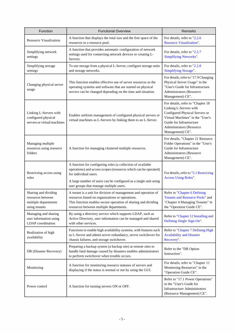
Function Functional Overview Remarks
Resource VisualizationA function that displays the total size and the free space of theresources in a resource pool.
For details, refer to "2.2.6Resource Visualization".
Simplifying networksettings
A function that provides automatic configuration of networksettings used for connecting network devices or creating L-Servers.
For details, refer to "2.2.7Simplifying Networks".
Simplifying storagesettings
To use storage from a physical L-Server, configure storage unitsand storage networks.
For details, refer to "2.2.8Simplifying Storage".
Changing physical serverusage
This function enables effective use of server resources as theoperating systems and software that are started on physicalservers can be changed depending on the time and situation.
For details, refer to "17.9 ChangingPhysical Server Usage" in the"User's Guide for InfrastructureAdministrators (ResourceManagement) CE".
Linking L-Servers withconfigured physicalservers or virtual machines
Enables uniform management of configured physical servers orvirtual machines as L-Servers by linking them to an L-Server.
For details, refer to "Chapter 18Linking L-Servers withConfigured Physical Servers orVirtual Machines" in the "User'sGuide for InfrastructureAdministrators (ResourceManagement) CE".
Managing multipleresources using resourcefolders
A function for managing clustered multiple resources.
For details, "Chapter 21 ResourceFolder Operations" in the "User'sGuide for InfrastructureAdministrators (ResourceManagement) CE".
Restricting access usingroles
A function for configuring roles (a collection of availableoperations) and access scopes (resources which can be operated)for individual users.
A large number of users can be configured as a single unit usinguser groups that manage multiple users.
For details, refer to "5.1 RestrictingAccess Using Roles".
Sharing and dividingresources betweenmultiple departmentsusing tenants
A tenant is a unit for division of management and operation ofresources based on organizations or operations.This function enables secure operation of sharing and dividingresources between multiple departments.
Refer to "Chapter 6 DefiningTenants and Resource Pools" and"Chapter 4 Managing Tenants" inthe "Operation Guide CE".
Managing and sharinguser information usingLDAP coordination
By using a directory service which supports LDAP, such asActive Directory, user information can be managed and sharedwith other services.
Refer to "Chapter 12 Installing andDefining Single Sign-On".
Realization of highavailability
Functions to enable high availability systems, with features suchas L-Server and admin server redundancy, server switchover forchassis failures, and storage switchover.
Refer to "Chapter 7 Defining HighAvailability and DisasterRecovery".
DR (Disaster Recovery)Preparing a backup system (a backup site) at remote sites tohandle fatal damage caused by disasters enables administratorsto perform switchover when trouble occurs.
Refer to the "DR OptionInstruction".
MonitoringA function for monitoring resource statuses of servers anddisplaying if the status is normal or not by using the GUI.
For details, refer to "Chapter 11Monitoring Resources" in the"Operation Guide CE".
Power control A function for turning servers ON or OFF.
Refer to "17.1 Power Operations"in the "User's Guide forInfrastructure Administrators(Resource Management) CE".
- 5 -

Function Functional Overview Remarks
Hardware maintenance
Functions to simplify hardware replacement. When connectedwith a SAN, it is not necessary to reconfigure storage units byconfiguring the I/O virtualization settings. By using VIOM, it isnot necessary to change the settings of software or networkdevices to refer to MAC addresses, as the MAC address, bootsettings, and network settings are automatically changed. VMhost maintenance can be easily performed, using VM HomePositions.
For details, refer to "Chapter 9Hardware Maintenance" in the"Operation Guide CE".
Network devicemonitoring
A function for monitoring resource statuses of network devicesand displaying if the status is normal or not on the GUI.Periodic or SNMP trap monitoring can be specified whennetwork devices are registered or changed.
- Periodic monitoring
Network devices are periodically monitored.
- Alive monitoring
Executes the "ping" command to the network device,and determines the existence of the device based on theresponse.
- Status monitoring
Collects MIB information for the device with SNMP,and determines the status from the MIB information.
- SNMP trap monitoring
Status monitoring (SNMP monitoring) is performed forSNMP trap (issued by the network device) reception.
- NetworkViewer Function
The following information is displayed in a comprehensiveNetworkViewer:
- Network configurations of physical servers and virtualmachines (Virtual switches, VM Guests)
- Statuses of network connections between resources
- VLAN configuration status within physical servers andvirtual machines
For details, refer to "11.4Monitoring Networks" in the"Operation Guide CE" and"Appendix A User Interface" in the"User's Guide for InfrastructureAdministrators (ResourceManagement) CE".
For the specification of themonitoring method, refer to "15.6Network ConfigurationInformation" in the "ReferenceGuide (Command/XML) CE".
Network maintenance A function for maintaining network devices.For details, refer to "Chapter 9Hardware Maintenance" in the"Operation Guide CE".
L-Server console screenThe L-Server console screen that displays the information ofphysical and virtual L-Servers can be opened with common,simple operations from the Resource Orchestrator screen.
For details, refer to "17.3 Using theL-Server Console" in the "User'sGuide for InfrastructureAdministrators (ResourceManagement) CE".
Managed Resources
Resource Orchestrator can be used to manage the resources described in the table below.
- 6 -

Table 2.3 Managed ResourcesResource Description
ChassisA chassis is an enclosure used to house server blades. It can monitor the statuses of servers, displaytheir properties, and control their power states.
Physical Server
This is a general term for any physical server. This term is used to distinguish physical servers fromvirtual machines that are created using server virtualization software such as VMware or Hyper-V.The following usage methods are available for physical servers:
- Managing unused physical servers as L-Servers by registering them with Resource Orchestrator
- Managing configured physical servers by linking them to L-Servers
VM hosts and physical OSs running on physical servers can be detected and registered as managedresources by Resource Orchestrator.
VM host
This refers to the server virtualization software running on a server to operate a virtual machine. Forexample, Windows Server 2008 R2 with Hyper-V roles added, VMware ESX for VMware, domain0 for RHEL5-Xen, VM hosts for RHEL-KVM, Citrix XenServer, OVM for x86, OVM for SPARC,or Global Zone for Solaris Zones.
VM hosts can be managed by monitoring their statuses, displaying their properties, and performingoperations such as HBA address rename and server switchover.When a VM host is registered, any VM guests on the VM host are automatically detected anddisplayed in the server tree. The power operations and migration operations, etc. of VM guests canbe performed from the server tree.
VM managementsoftware
This software manages multiple server virtualization software. For example, for VMware, it isvCenter Server, for Hyper-V, it is SCVMM, and for OVM for x86 2.2 or OVM for x86 3.2, it isOracle VM Manager.
VM management software can be integrated (registered) into Resource Orchestrator to enable theuse of functions for VM guests.
Server managementsoftware
Software used for managing multiple servers. The target servers can be controlled.
LAN switch (LAN switchblade)
The network switches that are mounted in a blade server chassis (LAN switch blades).Resource Orchestrator can monitor LAN switch blade statuses, display their properties, and managetheir VLAN configurations.
VM guest
This refers to the operating system running on a virtual machine.Resource Orchestrator can monitor VM guest statuses, display their properties, and control theirpower states.The following usage methods are available for physical servers:
- Managing new VM guests as L-Servers
- Managing configured virtual machines by linking them to L-Servers
Virtual switchThis is a virtual switch used to manage a VM guest network on the VM host.In Hyper-V, it represents the concept of virtual networks.It supports virtual switches, which are standard Hyper-V virtual network and VMware functions.
Disk resources
This refers to a disk resource allocated to a server.
- For EMC CLARiiON storage, EMC VNX storage, ETERNUS storage or NetApp FAS storage
The one that corresponds to the disk resource is LUN.
- For EMC Symmetrix DMX storage or EMC Symmetrix VMAX storage
The one that corresponds to the disk resource is device.
- For Storage Server on which FalconStor NSS operates
The one that corresponds to the disk resource is Virtual Device.
- For VM guests
- 7 -
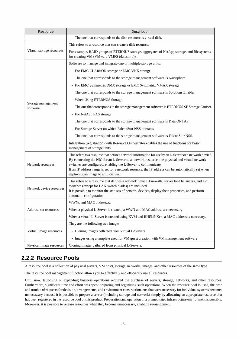
Resource Description
The one that corresponds to the disk resource is virtual disk.
Virtual storage resources
This refers to a resource that can create a disk resource.
For example, RAID groups of ETERNUS storage, aggregates of NetApp storage, and file systemsfor creating VM (VMware VMFS (datastore)).
Storage managementsoftware
Software to manage and integrate one or multiple storage units.
- For EMC CLARiiON storage or EMC VNX storage
The one that corresponds to the storage management software is Navisphere.
- For EMC Symmetrix DMX storage or EMC Symmetrix VMAX storage
The one that corresponds to the storage management software is Solutions Enabler.
- When Using ETERNUS Storage
The one that corresponds to the storage management software is ETERNUS SF Storage Cruiser.
- For NetApp FAS storage
The one that corresponds to the storage management software is Data ONTAP.
- For Storage Server on which FalconStor NSS operates
The one that corresponds to the storage management software is FalconStor NSS.
Integration (registration) with Resource Orchestrator enables the use of functions for basicmanagement of storage units.
Network resources
This refers to a resource that defines network information for use by an L-Server or a network device.By connecting the NIC for an L-Server to a network resource, the physical and virtual networkswitches are configured, enabling the L-Server to communicate.If an IP address range is set for a network resource, the IP address can be automatically set whendeploying an image to an L-Server.
Network device resources
This refers to a resource that defines a network device. Firewalls, server load balancers, and L2switches (except for LAN switch blades) are included.It is possible to monitor the statuses of network devices, display their properties, and performautomatic configuration.
Address set resources
WWNs and MAC addresses.
When a physical L-Server is created, a WWN and MAC address are necessary.
When a virtual L-Server is created using KVM and RHEL5-Xen, a MAC address is necessary.
Virtual image resources
They are the following two images.
- Cloning images collected from virtual L-Servers
- Images using a template used for VM guest creation with VM management software
Physical image resources Cloning images gathered from physical L-Servers.
2.2.2 Resource PoolsA resource pool is a collection of physical servers, VM hosts, storage, networks, images, and other resources of the same type.
The resource pool management function allows you to effectively and efficiently use all resources.
Until now, launching or expanding business operations required the purchase of servers, storage, networks, and other resources.Furthermore, significant time and effort was spent preparing and organizing such operations. When the resource pool is used, the timeand trouble of requests for decision, arrangements, and environment construction, etc. that were necessary for individual systems becomesunnecessary because it is possible to prepare a server (including storage and network) simply by allocating an appropriate resource thathas been registered in the resource pool of this product. Preparation and operation of a premeditated infrastructure environment is possible.Moreover, it is possible to release resources when they become unnecessary, enabling re-assignment.
- 8 -
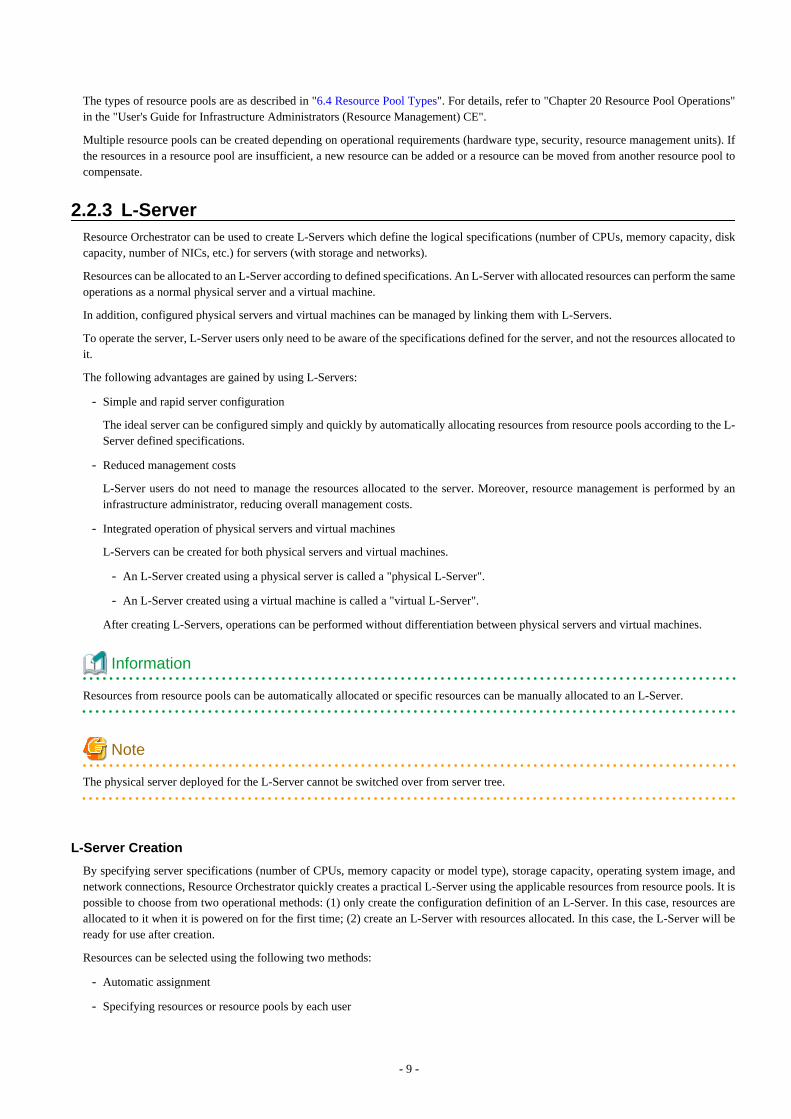
The types of resource pools are as described in "6.4 Resource Pool Types". For details, refer to "Chapter 20 Resource Pool Operations"in the "User's Guide for Infrastructure Administrators (Resource Management) CE".
Multiple resource pools can be created depending on operational requirements (hardware type, security, resource management units). Ifthe resources in a resource pool are insufficient, a new resource can be added or a resource can be moved from another resource pool tocompensate.
2.2.3 L-ServerResource Orchestrator can be used to create L-Servers which define the logical specifications (number of CPUs, memory capacity, diskcapacity, number of NICs, etc.) for servers (with storage and networks).
Resources can be allocated to an L-Server according to defined specifications. An L-Server with allocated resources can perform the sameoperations as a normal physical server and a virtual machine.
In addition, configured physical servers and virtual machines can be managed by linking them with L-Servers.
To operate the server, L-Server users only need to be aware of the specifications defined for the server, and not the resources allocated toit.
The following advantages are gained by using L-Servers:
- Simple and rapid server configuration
The ideal server can be configured simply and quickly by automatically allocating resources from resource pools according to the L-Server defined specifications.
- Reduced management costs
L-Server users do not need to manage the resources allocated to the server. Moreover, resource management is performed by aninfrastructure administrator, reducing overall management costs.
- Integrated operation of physical servers and virtual machines
L-Servers can be created for both physical servers and virtual machines.
- An L-Server created using a physical server is called a "physical L-Server".
- An L-Server created using a virtual machine is called a "virtual L-Server".
After creating L-Servers, operations can be performed without differentiation between physical servers and virtual machines.
Information
Resources from resource pools can be automatically allocated or specific resources can be manually allocated to an L-Server.
Note
The physical server deployed for the L-Server cannot be switched over from server tree.
L-Server Creation
By specifying server specifications (number of CPUs, memory capacity or model type), storage capacity, operating system image, andnetwork connections, Resource Orchestrator quickly creates a practical L-Server using the applicable resources from resource pools. It ispossible to choose from two operational methods: (1) only create the configuration definition of an L-Server. In this case, resources areallocated to it when it is powered on for the first time; (2) create an L-Server with resources allocated. In this case, the L-Server will beready for use after creation.
Resources can be selected using the following two methods:
- Automatic assignment
- Specifying resources or resource pools by each user
- 9 -
L-Server specifications can be specified by the following two methods.
- Selecting an L-Server template
For details on how to create an L-Server using an L-Server template (with L-Server specifications pre-defined), refer to "16.1 CreationUsing an L-Server Template" in the "User's Guide for Infrastructure Administrators (Resource Management) CE".
- Manually specifying each L-Server specification without using an L-Server template
For details on how to create an L-Server individually (without using an L-Server template), refer to "16.2 Creation of Physical L-Servers Using Parameters" or "16.3 Creation of Virtual L-Servers Using Parameters" in the "User's Guide for InfrastructureAdministrators (Resource Management) CE".
Basic operations, such as startup, shutdown, and delete, can be performed for an L-Server in the same way as for a typical server. L-Serverusers do not require detailed knowledge of the resources allocated to the server in order to operate it.
The following operations can be performed:
- Changing of L-Server configurations
Configurations of resources to allocate to the L-Server can be changed.Refer to "17.2 Modifying" in the "User's Guide for Infrastructure Administrators (Resource Management) CE".
- Moving an L-Server between servers (migration) (For virtual L-Servers)
The function that moves a virtual L-Server to another VM host without stopping it.For details, refer to "17.7 Migration between VM Hosts" in the "User's Guide for Infrastructure Administrators (Resource Management)CE".
- Snapshot (For virtual L-Servers)
The function that saves the content of the system disk and data disk of a virtual L-Server disk at a certain point of time.For details, refer to "17.6.1 Snapshot" in the "User's Guide for Infrastructure Administrators (Resource Management) CE".
- 10 -
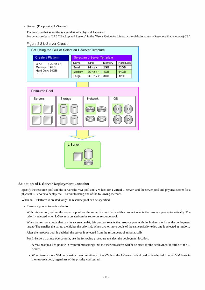
- Backup (For physical L-Servers)
The function that saves the system disk of a physical L-Server.For details, refer to "17.6.2 Backup and Restore" in the "User's Guide for Infrastructure Administrators (Resource Management) CE".
Figure 2.2 L-Server Creation
Selection of L-Server Deployment Location
Specify the resource pool and the server (the VM pool and VM host for a virtual L-Server, and the server pool and physical server for aphysical L-Server) to deploy the L-Server to using one of the following methods.
When an L-Platform is created, only the resource pool can be specified.
- Resource pool automatic selection
With this method, neither the resource pool nor the server is specified, and this product selects the resource pool automatically. Thepriority selected when L-Server is created can be set to the resource pool.
When two or more pools that can be accessed exist, this product selects the resource pool with the higher priority as the deploymenttarget (The smaller the value, the higher the priority). When two or more pools of the same priority exist, one is selected at random.
After the resource pool is decided, the server is selected from the resource pool automatically.
For L-Servers that use overcommit, use the following procedure to select the deployment location.
- A VM host in a VM pool with overcommit settings that the user can access will be selected for the deployment location of the L-Server.
- When two or more VM pools using overcommit exist, the VM host the L-Server is deployed to is selected from all VM hosts inthe resource pool, regardless of the priority configured.
- 11 -

- Resource pool specification
The server is selected from the specified resource pool automatically.
For a virtual L-Server, it is necessary to specify the resource pool according to the overcommit setting.
- Server specification
The L-Server is deployed to the specified server.
For a virtual L-Server, it is necessary to specify a VM host in the resource pool according to the overcommit setting.
The server that is the deployment target must meet all of the following requirements.
- The VM host is powered on
- Status is "normal"
- Maintenance mode is not set
For details on maintenance mode, refer to "Appendix C Maintenance Mode" in the "User's Guide for Infrastructure Administrators(Resource Management) CE".
- The maintenance mode of the server virtualization software is not set (For virtual L-Server)
- The conditions specified during L-Server creation are met
When creating a virtual L-Server, if the deployment target VM host in the VM pool is selected automatically, the VM host is selectedusing the conditions above, as shown below.
- When using L-Server templates
The VM host on which another L-Server that was created from the same L-Server template is placed is searched for, and then the L-Server is created.
If there is insufficient space on the VM host, a VM host that has more capacity is searched for, and then the L-Server is created.
This enables reduction of waste by fragmenting the free space of VM hosts among all VM hosts.
For L-Server templates that have overcommit enabled, if none of the searched VM hosts has sufficient space available, select a VMhost and create an L-Server.
- When not using L-Server templates
A VM host that has more capacity is searched for, and then the L-Server is created.
- When the exclusion function of an L-Server has been set
The L-Server is created on a VM host that other L-Servers do not use.The L-Servers on an L-Platform are configured for exclusive operation from all other L-Servers on the L-Platform.
- When the HA function or automatic re-installation function (examples: VMware HA or VMware DRS) of the VM product was enabled
The VM host is selected by the VM product.
[KVM] [Solaris Zones] [OVM for SPARC]A VM host in which an unused disk resource exists with the disk capacity specified as virtual L-Server is searched for, and then the L-Server is created.
Simplifying Installing Using Cloning
Cloning is the function to distribute cloning images made from the content of the system disk of one server to another physical L-Server.
When a cloning image is created, network-specific settings such as host names and IP addresses are removed from the cloning image.This network-specific configuration is dynamically reconfigured on the servers to which the cloning image is distributed.
This makes it possible to create duplicates of existing servers that will use the same operating system and software.
- 12 -
Simplifying Configuration Using I/O Virtualization
I/O virtualization via HBA address rename (*) allows storage devices to be configured independently and prior to the rest of the serverinstallation process. Servers can then be installed and set up without the involvement of storage administrators.
* Note: Refer to "2.2.9 I/O Virtualization".
L-Server for Infrastructure Administrator
The L-Server for the infrastructure administrator is an L-Server that cannot be used by the tenant administrator or tenant users. Only thetenant administrator and the tenant user can use a normal L-Server.
It is created for the following purpose.
- When the infrastructure administrator collects the cloning image
The infrastructure administrator creates the cloning image, and releases it to the tenant administrator and tenant users.
For details how to create an L-Server for an infrastructure administrator, refer to "Chapter 14 Creating an L-Server for an InfrastructureAdministrator" in the "Setup Guide CE".
For details how to collect cloning images, refer to "Chapter 15 Collecting and Registering Cloning Images" in the "Setup Guide CE".
- When installing a VM host on a physical L-Server
The setting of the network and storage can be simplified using the functions of the physical L-Server when creating the VM host.Moreover, high availability operation and Disaster Recovery can be performed.
For details how to set up, refer to the following:
- Installing VM Hosts on Physical L-Servers
Refer to "Appendix D Installing VM Hosts on Physical L-Servers" in the "Setup Guide CE".
- Blade Chassis High Availability
Refer to "18.1.2 Blade Chassis High Availability" in the "Operation Guide CE".
- Disaster Recovery
For details, refer to "DR Option Instruction".
- When the software used on L-Server for the purpose of the infrastructure management of the VM management product etc. is installed,the simplification, the high availability operation, and Disaster Recovery of the construction of the VM management product can beoperated.
Changing Physical Server Usage
The usage change of a physical server is a function to prepare more L-Servers than the number of physical servers, and to start the L-Server to be switched to. Because the usage of a physical server can be changed using this function according to the time and situation,the resources of servers can be used effectively.
The boot disk and Internet Protocol address of an L-Server are retained while another L-Server uses a physical server.
This function can be used when an L-Server is actually a physical server. With virtual machines, as it is possible to deploy multiple L-Servers on a single VM host without making any settings, it is possible to get the same effect as changing the usage of a physical serverby selecting the L-Server to start.
This function has the following two uses.
- One physical server used for the switchover of multiple L-Servers
The physical server that starts an L-Server will always be the same server.
- An unused physical server in a server pool used for the switchover of multiple L-Servers
The physical server allocated to an L-Server differs depending on the availability of the server pool.
- 13 -
For details, refer to "17.9 Changing Physical Server Usage" in the "User's Guide for Infrastructure Administrators (Resource Management)CE".
Changing VM Guest Locations (Migration)
The operation (migration) that moves the VM guest between physical servers can be done from this product through coordination withthe VM management product (VMware vCenter Server etc.) or the VM host (VM host of KVM).
Regrouping of all VM guests to a subset of servers and shut down of any unused servers or chassis to reduce overall power consumption.
When server maintenance becomes necessary, VM guests can be migrated to alternative servers and their applications kept alive duringmaintenance work.
2.2.4 L-PlatformThis section explains L-Platforms.
An L-Platform is a logical resource used to collectively manage an entire system (platform) composed of two or more servers in ahierarchical system (Web/AP/DB), with a network.
The setting and the operation of two or more servers, storage, and networks can be simplified by the use of an L-Platform.Resource Orchestrator can be used to deploy and operate L-Platforms.An L-Platform defines the following combination of resources:
- L-Server
An L-Platform is a logical server that manages physical servers and virtual servers (VM) together.For details on L-Servers, refer to "2.2.3 L-Server".
- Network resources
This is a resource that expresses the network where it connects between L-Servers. Using network resources it is possible toautomatically configure switches and virtual switches, and connect an L-Server to a network.For details, refer to "2.2.7 Simplifying Networks".
- Firewall resources
In a hierarchical system, this resource ensures the security of each tier.
- Server load balancer resources
This resource distributes the workload across multiple servers, reducing the delay in response when there is concentrated traffic orserver failure.
The configuration of an L-Platform is shown below.
- 14 -
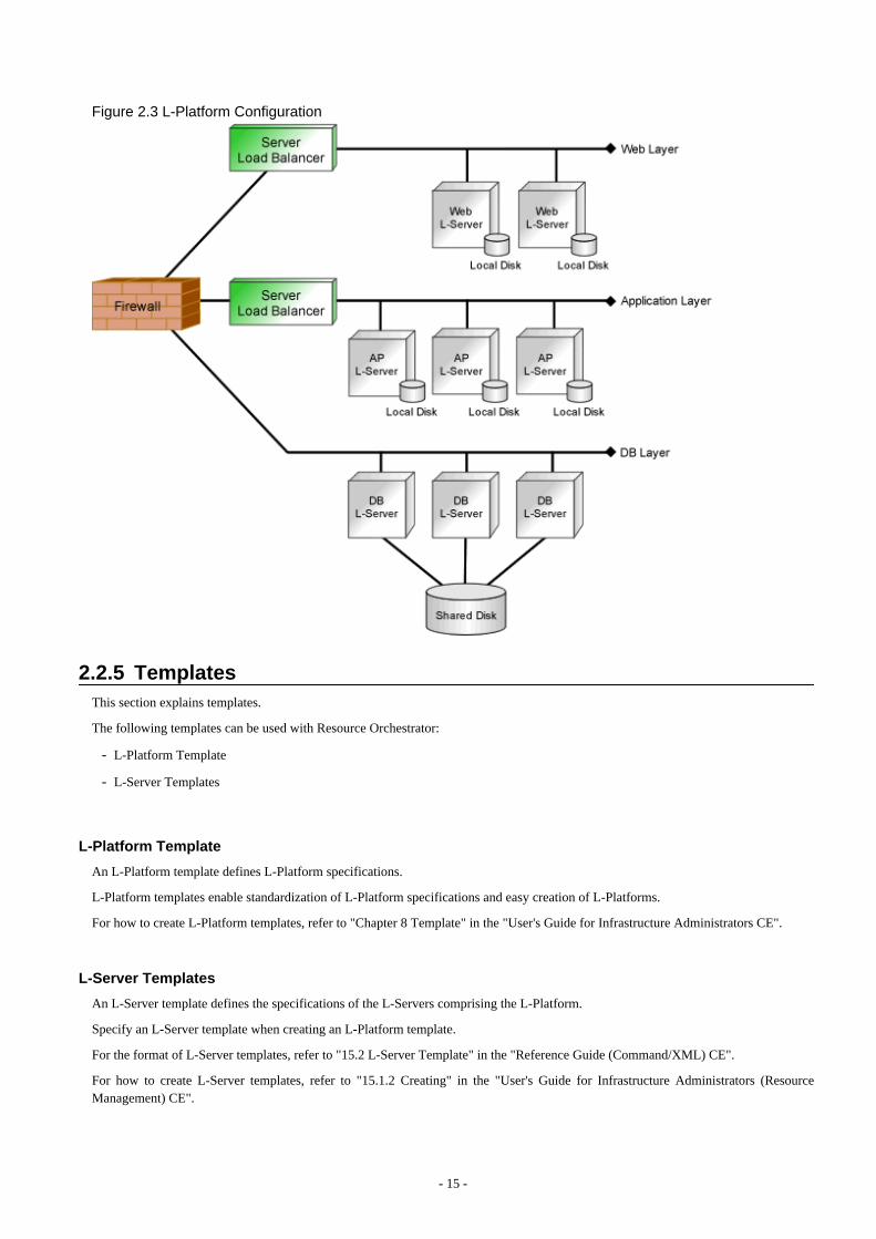
Figure 2.3 L-Platform Configuration
2.2.5 TemplatesThis section explains templates.
The following templates can be used with Resource Orchestrator:
- L-Platform Template
- L-Server Templates
L-Platform Template
An L-Platform template defines L-Platform specifications.
L-Platform templates enable standardization of L-Platform specifications and easy creation of L-Platforms.
For how to create L-Platform templates, refer to "Chapter 8 Template" in the "User's Guide for Infrastructure Administrators CE".
L-Server Templates
An L-Server template defines the specifications of the L-Servers comprising the L-Platform.
Specify an L-Server template when creating an L-Platform template.
For the format of L-Server templates, refer to "15.2 L-Server Template" in the "Reference Guide (Command/XML) CE".
For how to create L-Server templates, refer to "15.1.2 Creating" in the "User's Guide for Infrastructure Administrators (ResourceManagement) CE".
- 15 -
2.2.6 Resource Visualization
Display of Total Capacity of Resources in the Resource Pool and Free Space
The total capacity and the free space of the resources in the resource pool are displayed, and the availability can easily be checked fromthe [dashboard (Pool conditions)] tab of the ROR console.
For how to use the [dashboard (Pool Conditions)] tab of the ROR console, refer to "Chapter 4 Dashboard (Pool Conditions)" in the "User'sGuide for Infrastructure Administrators CE".
Display of the Number of L-Servers Each L-Server Templates can Create
The number of L-Servers that can be created for each L-Server template can be displayed for the specified L-Server template.
For details on the L-Server conversion view, refer to "20.6 Viewing" in the "User's Guide for Infrastructure Administrators (ResourceManagement) CE".
Relation Management of Physical Servers and Virtual Servers
Resource Orchestrator provides an integrated management console for environments composed of physical and virtual servers.
The [Resource] tab of the ROR console supports management of server configurations, monitoring of failures, and determination of thecauses and range of effects of problems.
- Resource Orchestrator provides a tree-based view of chassis and server hardware and their operating systems (physical OS, VM host,or VM guest). This enables easy confirmation and tracking of relationships between chassis, servers, and operating systems.
- Resource Orchestrator monitors server hardware and displays icons representative of each server's status.
Resource Orchestrator also allows administrators to manage both physical and virtual servers in a uniform manner. Once registered,resources can be managed uniformly regardless of server models, types of server virtualization software, or differences between physicaland virtual servers.
Easy Server Monitoring
When managing PRIMERGY BX servers, BladeViewer can be used to easily check server statuses and perform other daily operations.In BladeViewer, server statuses are displayed in a format similar to the physical configuration of a blade server system, making servermanagement and operation more intuitive. BladeViewer provides the following features:
- Display of server blades' mount statuses.
- An intuitive way to monitor and control the power statuses of multiple server blades.
- Easier visualization of which applications are running on each server blade. This helps to quickly identify any affected applicationswhen a hardware fault occurs on a server blade.
Monitoring of Power Consumption
By activating the power monitoring feature, it is possible to monitor trends in power consumption for resources equipped with powermonitoring capabilities, or resources connected to a registered power monitoring device (PDU or UPS). The power consumption dataregularly collected from the power monitoring environment can be output to a file in CSV format or as a graph.
2.2.7 Simplifying NetworksVLAN or IP address settings for LAN switch blades, virtual switches, and L2 switches is automatically performed based on the definitioninformation of network resources in Resource Orchestrator. For L2 switches, firewalls, and server load balancers, configuring, modifying,or deleting the definitions that include VLAN settings is automatically performed using scripts. Scripts are prepared for each model of thenetwork devices by infrastructure administrators.
- 16 -
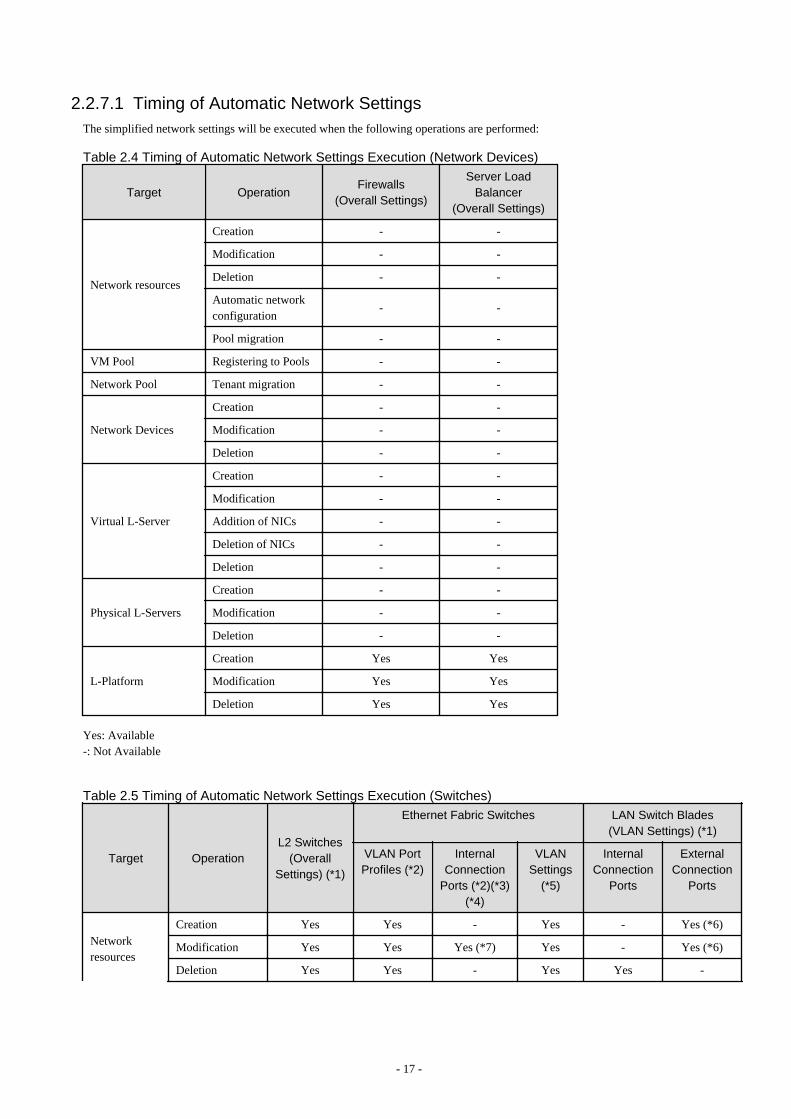
2.2.7.1 Timing of Automatic Network SettingsThe simplified network settings will be executed when the following operations are performed:
Table 2.4 Timing of Automatic Network Settings Execution (Network Devices)
Target OperationFirewalls
(Overall Settings)
Server LoadBalancer
(Overall Settings)
Network resources
Creation - -
Modification - -
Deletion - -
Automatic networkconfiguration
- -
Pool migration - -
VM Pool Registering to Pools - -
Network Pool Tenant migration - -
Network Devices
Creation - -
Modification - -
Deletion - -
Virtual L-Server
Creation - -
Modification - -
Addition of NICs - -
Deletion of NICs - -
Deletion - -
Physical L-Servers
Creation - -
Modification - -
Deletion - -
L-Platform
Creation Yes Yes
Modification Yes Yes
Deletion Yes Yes
Yes: Available-: Not Available
Table 2.5 Timing of Automatic Network Settings Execution (Switches)
Target OperationL2 Switches
(OverallSettings) (*1)
Ethernet Fabric Switches LAN Switch Blades(VLAN Settings) (*1)
VLAN PortProfiles (*2)
InternalConnection
Ports (*2)(*3)(*4)
VLANSettings
(*5)
InternalConnection
Ports
ExternalConnection
Ports
Networkresources
Creation Yes Yes - Yes - Yes (*6)
Modification Yes Yes Yes (*7) Yes - Yes (*6)
Deletion Yes Yes - Yes Yes -
- 17 -
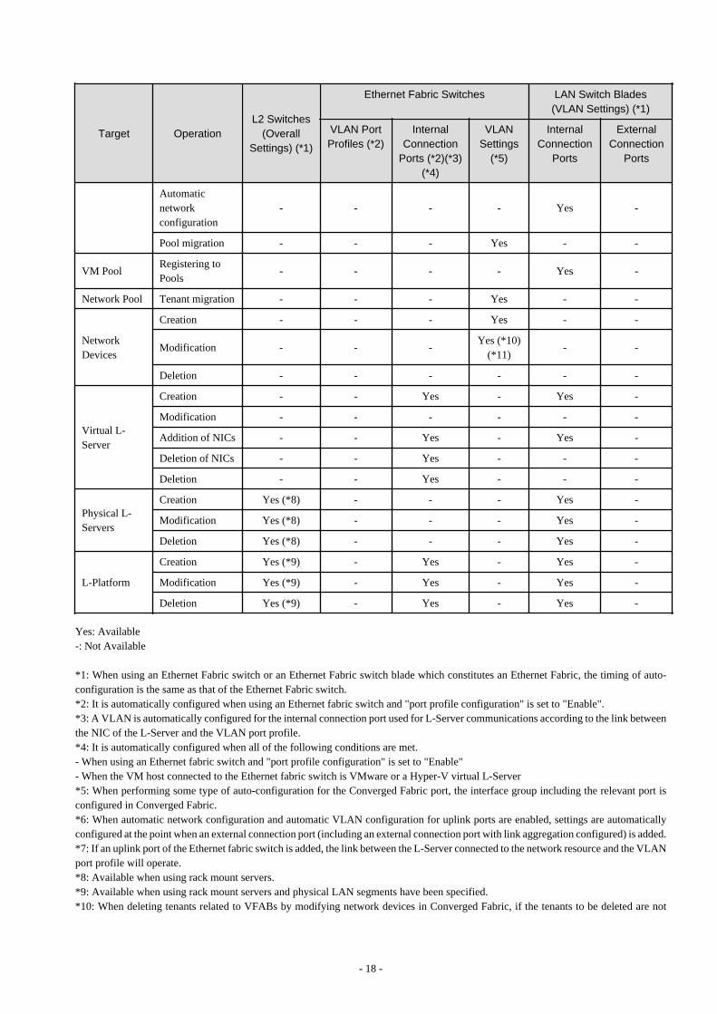
Target OperationL2 Switches
(OverallSettings) (*1)
Ethernet Fabric Switches LAN Switch Blades(VLAN Settings) (*1)
VLAN PortProfiles (*2)
InternalConnection
Ports (*2)(*3)(*4)
VLANSettings
(*5)
InternalConnection
Ports
ExternalConnection
Ports
Automaticnetworkconfiguration
- - - - Yes -
Pool migration - - - Yes - -
VM PoolRegistering toPools
- - - - Yes -
Network Pool Tenant migration - - - Yes - -
NetworkDevices
Creation - - - Yes - -
Modification - - -Yes (*10)
(*11)- -
Deletion - - - - - -
Virtual L-Server
Creation - - Yes - Yes -
Modification - - - - - -
Addition of NICs - - Yes - Yes -
Deletion of NICs - - Yes - - -
Deletion - - Yes - - -
Physical L-Servers
Creation Yes (*8) - - - Yes -
Modification Yes (*8) - - - Yes -
Deletion Yes (*8) - - - Yes -
L-Platform
Creation Yes (*9) - Yes - Yes -
Modification Yes (*9) - Yes - Yes -
Deletion Yes (*9) - Yes - Yes -
Yes: Available-: Not Available
*1: When using an Ethernet Fabric switch or an Ethernet Fabric switch blade which constitutes an Ethernet Fabric, the timing of auto-configuration is the same as that of the Ethernet Fabric switch.*2: It is automatically configured when using an Ethernet fabric switch and "port profile configuration" is set to "Enable".*3: A VLAN is automatically configured for the internal connection port used for L-Server communications according to the link betweenthe NIC of the L-Server and the VLAN port profile.*4: It is automatically configured when all of the following conditions are met.- When using an Ethernet fabric switch and "port profile configuration" is set to "Enable"- When the VM host connected to the Ethernet fabric switch is VMware or a Hyper-V virtual L-Server*5: When performing some type of auto-configuration for the Converged Fabric port, the interface group including the relevant port isconfigured in Converged Fabric.*6: When automatic network configuration and automatic VLAN configuration for uplink ports are enabled, settings are automaticallyconfigured at the point when an external connection port (including an external connection port with link aggregation configured) is added.*7: If an uplink port of the Ethernet fabric switch is added, the link between the L-Server connected to the network resource and the VLANport profile will operate.*8: Available when using rack mount servers.*9: Available when using rack mount servers and physical LAN segments have been specified.*10: When deleting tenants related to VFABs by modifying network devices in Converged Fabric, if the tenants to be deleted are not
- 18 -
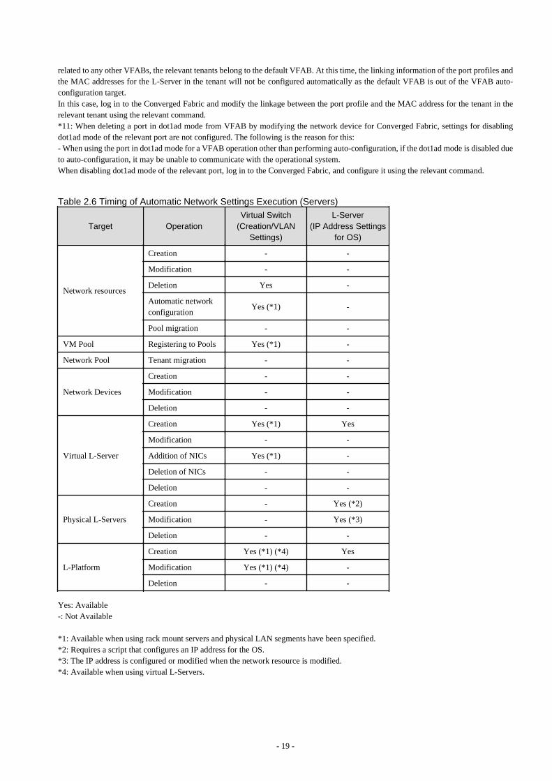
related to any other VFABs, the relevant tenants belong to the default VFAB. At this time, the linking information of the port profiles andthe MAC addresses for the L-Server in the tenant will not be configured automatically as the default VFAB is out of the VFAB auto-configuration target.In this case, log in to the Converged Fabric and modify the linkage between the port profile and the MAC address for the tenant in therelevant tenant using the relevant command.*11: When deleting a port in dot1ad mode from VFAB by modifying the network device for Converged Fabric, settings for disablingdot1ad mode of the relevant port are not configured. The following is the reason for this:- When using the port in dot1ad mode for a VFAB operation other than performing auto-configuration, if the dot1ad mode is disabled dueto auto-configuration, it may be unable to communicate with the operational system.When disabling dot1ad mode of the relevant port, log in to the Converged Fabric, and configure it using the relevant command.
Table 2.6 Timing of Automatic Network Settings Execution (Servers)
Target OperationVirtual Switch
(Creation/VLANSettings)
L-Server(IP Address Settings
for OS)
Network resources
Creation - -
Modification - -
Deletion Yes -
Automatic networkconfiguration
Yes (*1) -
Pool migration - -
VM Pool Registering to Pools Yes (*1) -
Network Pool Tenant migration - -
Network Devices
Creation - -
Modification - -
Deletion - -
Virtual L-Server
Creation Yes (*1) Yes
Modification - -
Addition of NICs Yes (*1) -
Deletion of NICs - -
Deletion - -
Physical L-Servers
Creation - Yes (*2)
Modification - Yes (*3)
Deletion - -
L-Platform
Creation Yes (*1) (*4) Yes
Modification Yes (*1) (*4) -
Deletion - -
Yes: Available-: Not Available
*1: Available when using rack mount servers and physical LAN segments have been specified.*2: Requires a script that configures an IP address for the OS.*3: The IP address is configured or modified when the network resource is modified.*4: Available when using virtual L-Servers.
- 19 -
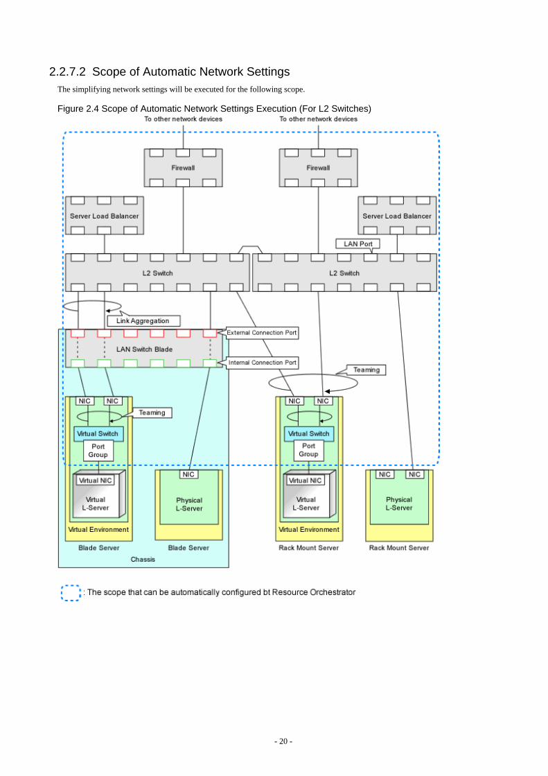
2.2.7.2 Scope of Automatic Network SettingsThe simplifying network settings will be executed for the following scope.
Figure 2.4 Scope of Automatic Network Settings Execution (For L2 Switches)
- 20 -
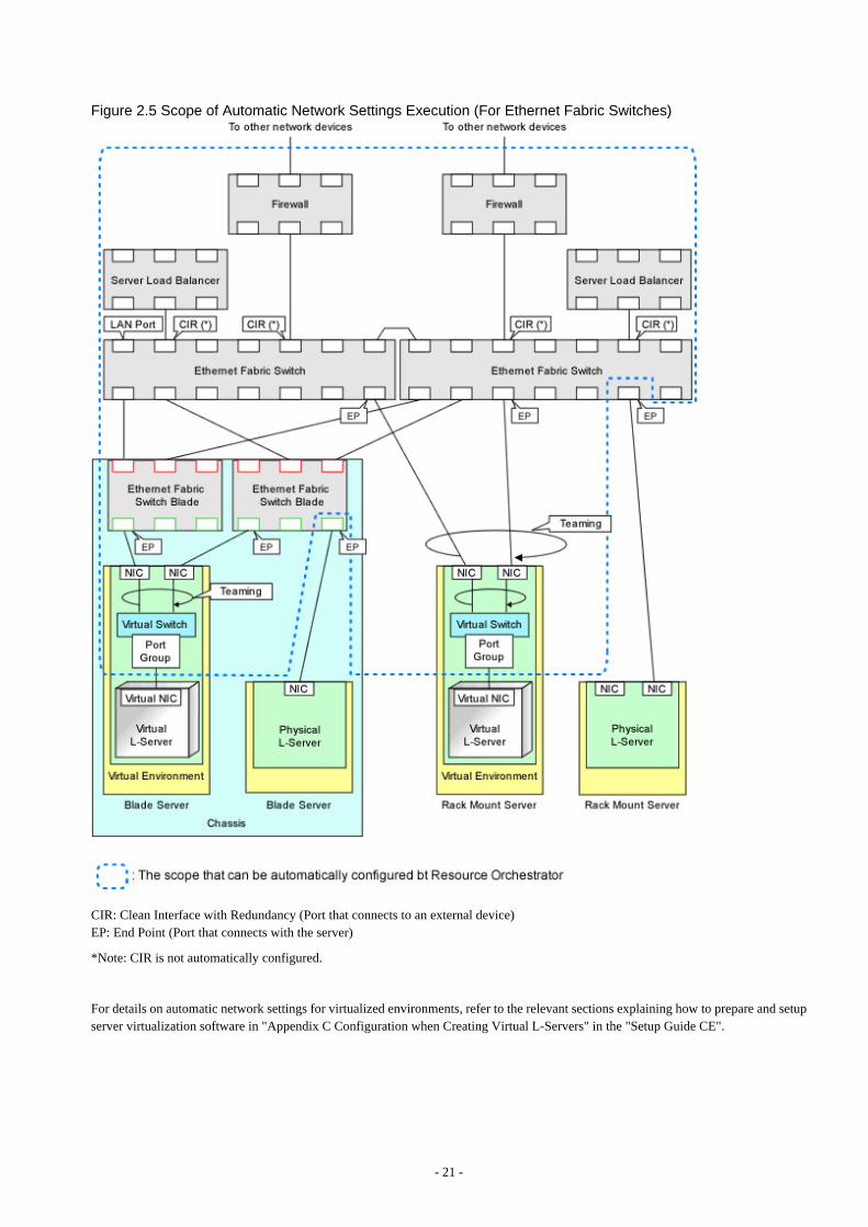
Figure 2.5 Scope of Automatic Network Settings Execution (For Ethernet Fabric Switches)
CIR: Clean Interface with Redundancy (Port that connects to an external device)EP: End Point (Port that connects with the server)
*Note: CIR is not automatically configured.
For details on automatic network settings for virtualized environments, refer to the relevant sections explaining how to prepare and setupserver virtualization software in "Appendix C Configuration when Creating Virtual L-Servers" in the "Setup Guide CE".
- 21 -
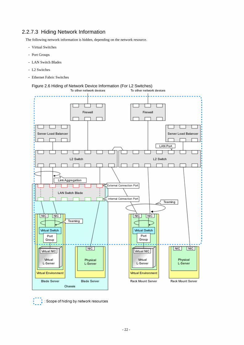
2.2.7.3 Hiding Network InformationThe following network information is hidden, depending on the network resource.
- Virtual Switches
- Port Groups
- LAN Switch Blades
- L2 Switches
- Ethernet Fabric Switches
Figure 2.6 Hiding of Network Device Information (For L2 Switches)
- 22 -

Figure 2.7 Hiding of Network Device Information (For Ethernet Fabric Switches)
CIR: Clean Interface with Redundancy (Port that connects to an external device)EP: End Point (Port that connects with the server)
2.2.7.4 Network Device Automatic ConfigurationThere are two types of modes for auto-configuration of network devices.
- User Customization Mode
Firewalls, server load balancers, and L2 switches are the targets.
- 23 -
- Simple Configuration Mode
Only firewalls (NSAppliance) are the targets.
User Customization Mode
The infrastructure administrator creates the ruleset necessary to configure the definitions for the network devices (firewalls, server loadbalancers, and L2 switches), and registers it in Resource Orchestrator.In Resource Orchestrator, perform auto-configuration for the target network devices using the ruleset registered by the infrastructureadministrator.
For details on preparation for auto-configuration using user customization mode, refer to "Appendix F Preparing for AutomaticConfiguration and Operation of Network Devices".
For details on operation image of modifying configuration of firewalls using user customization mode, refer to "When an L-Platform thatuses a firewall is deployed without the use of a ruleset" in "8.3.9 Setup Firewall" in the "User's Guide for Tenant Administrators CE" or"5.3.8 Setup Firewall" in the "User's Guide for Tenant Users CE".
For details on operation image of modifying configuration of firewalls using user customization mode, refer to "8.3.11 Server LoadBalancer (SLB) Settings" in the "User's Guide for Tenant Administrators CE" or "5.3.10 Server Load Balancer (SLB) Settings" in the"User's Guide for Tenant Users CE".
Simple Configuration Mode
The infrastructure administrator is not required to create the rulesets necessary for configuring definitions for network devices (firewalls)in advance.In Resource Orchestrator, it is possible to easily perform auto-configuration by using the defined definitions.
.Simple configuration mode enables deployment of L-Platforms using firewalls, without using rulesets.For details on the logical network configuration realized using simple configuration mode, the target devices, or configuration details,refer to "Appendix I Auto-configuration and Operations of Network Devices Using Simple Configuration Mode".
For details on operation image of modifying configuration of firewalls using simple configuration mode, refer to "When an L-Platformthat uses a firewall is deployed without the use of a ruleset" in "8.3.9 Setup Firewall" in the "User's Guide for Tenant Administrators CE"or "5.3.8 Setup Firewall" in the "User's Guide for Tenant Users CE".
Auto-configuration Timing and Images
This section explains auto-configuration timing and images.
- Automatic configuration of firewalls and server load balancers when creation, modification, or deletion of an L-Platform is performed
The detailed timing is as follows:
- When an L-Platform is created from an L-Platform template that includes a network device (firewall or server load balancer)
- When L-Server addition or deletion is performed for an L-Platform
- When the settings of a network device (firewall or server load balancers) in an L-Platform are modified
- When an L-Platform created from an L-Platform template that includes a network device (firewall or server load balancer) isdeleted
- Automatic configuration for L2 switches when creation, modification, or deletion of an network resource is performed
- 24 -

- Automatic configuration for L2 switches when creation or modification of a physical L-Server is performed on rack mount servers
Figure 2.8 Network Device Automatic Configuration Image
Recovery (deletion of incomplete settings, etc.) of network devices can be performed by preparing a recovery script in advance in caseautomatic configuration of network devices fails.
Figure 2.9 Network Device Automatic Configuration Image (Recovery Process)
2.2.7.5 Network Device Configuration File ManagementThe following files are available as network device (firewall, server load balancer and L2 Switch) configuration files.
- Network device configuration files
A configuration file containing settings related to communication, such as address and VLAN information of devices and interfaces,and rules for firewalls and server load balancers
- Network device environment files
Files required for the operation of devices such as CA certificates, user authentication databases and user customized information(excluding network device configuration files)
In this product, a function which manages device configuration files using generations is offered. Using this function modification changescan be checked and restoration of configurations can be performed easily when network devices are exchanged.
- 25 -
The following features are provided by the network device configuration file management function.
- Backing up and restoration of configuration files
Network device configuration files can be backed up by this product and managed using generations.Further, the latest configuration files which already backed up can be restored to network devices.
- Export of configuration files
The files that are backed up and managed using generations can be exported from the manager.
- Backing up and restoration of environment files
Network device configuration files can be backed up to this product.Further, backed up environment files can be restored to network devices.
- Export of environment files
The backed up files can be exported to the infrastructure admin's terminal.
- Registration of external server information
For network devices which do not have an ftp server, the information of an external ftp server, which is used for backing up andrestoration of network devices, can be registered.
Specify this external server in the network configuration information (XML definition) file when registering the network device.
2.2.7.6 Simple Network MonitoringThis section provides a brief overview of simple network monitoring.
Visualize Networks (NetworkViewer Function)
For PRIMERGY BX servers, Resource Orchestrator provides a NetworkViewer function, which helps visualize and relate physicalnetworks (between servers and LAN switches) together with virtualized networks (from VLANs or virtual switches used in servervirtualization software). It has the following features.
- Automatic detection and display of network connections (topology) and link statuses between heterogeneous network resources.
- Facilitates overall network consistency diagnostics and identification of the resources (physical and virtual) affected by a networkissue.
- Displays comprehensive content that can be used in communication between server and network administrators, thus smoothing outcoordination between the two parties.
For details on the functions of NetworkViewer, refer to "Table 2.5 Functions Available for LAN Switches" in "2.2 Function Overview"in the "Design Guide VE".
Note
For VMware virtual switches, network links are only displayed when using the standard switches.When using switches other than the standard switches, such as distributed virtual switches, those virtual switches and the network linksare not displayed.
Status Monitoring
Resource Orchestrator monitors the status of network devices (Firewalls, server load balancers, and L2 switches) in order to automaticallyperform network settings for them.
2.2.8 Simplifying StorageThis section provides a brief overview of simplified storage setup.
When preparing physical servers and virtual machines, it was difficult to smoothly provide servers as the configuration of storage unitsand the storage network was necessary.
- 26 -
Resource Orchestrator enables quick allocation of storage through coordination with storage management software or VM managementsoftware.
In this product, the following two storage resources are managed.
- Virtual Storage Resources
Virtual storage resource indicates the following resources.
When storage management software is registered to Resource Orchestrator, the storage information controlled by the storagemanagement software is automatically obtained and detected as a virtual storage resource. Virtual storage resources do not need tobe individually registered as resources.
The resources can be managed as virtual storage resources using the same operations.
- For physical servers
An original resource used to create LUN such as ETERNUS RAID groups or NetApp aggregates on storage units
- For VM
A file system for creation of VMs and virtual disks such as VMFS (datastore) of VMware, shared volumes for clusters of Hyper-V, or storage repositories of OVM for x86
- Disk Resources
A disk resource refers to a disk resource allocated to a server.
For disk resources created in advance such as LUNs, storage information is automatically obtained when storage management softwareis registered, and they are detected as disk resources. Therefore, it is not necessary to register disk resources individually.
- For physical servers
- When using ETERNUS storage, NetApp storage, EMC CLARiiON and EMC VNX
LUN (Logical Unit Number)
- When using EMC Symmetrix DMX or EMX Symmetrix VMAX
Device
- For Storage Server on which FalconStor NSS operates
Virtual Device
- For VM
Virtual Disk
Allocation of Storage to an L-Server
In Resource Orchestrator, use the following procedure to allocate a disk resource to an L-Server:
- Method involving allocation of disk resources with specified sizes that have been automatically created by this product from storageresources (Automatic generation from virtual storage)
- Method involving allocation of disk resources that have been created in advance using storage management software to L-Servers(Creation of disk resources in advance)
The allocation strategy on storage differs depending on the type of the L-Server and the storage device used.
- Allocating Storage to a Physical L-Server
For details, refer to "Allocating Storage to a Physical L-Server".
The following storage allocation methods and storage types are available for physical L-Servers.
- 27 -
Table 2.7 Storage Allocation Methods and Storage Types for Physical L-ServersAllocation Method Storage Type
Allocate disk resources automaticallycreated from virtual storage resources
- ETERNUS Storage
- NetApp FAS Storage
Allocate disk resources that werecreated in advance
- ETERNUS Storage
- NetApp FAS Storage
- EMC CLARiiON Storage or EMC VNX Storage
- EMC Symmetrix DMX Storage
- EMC Symmetrix VMAX Storage
- Storage Server on which FalconStor NSS operates
- Allocating Storage to a Virtual L-Server
For details, refer to "Allocating Storage to a Virtual L-Server".
Storage Allocation Methods and Storage Types and Server Virtualization Types for Virtual L-Servers are as follows.
Table 2.8 Storage Allocation Methods and Storage Types and Server Virtualization Types for Virtual L-Servers
Allocation Method Storage Type
Allocate disk resources automatically createdfrom virtual storage resources
- VMware
- Hyper-V
- OVM for x86
- RHEL5-Xen
- KVM
Allocate disk resources that were created inadvance
- KVM
- Solaris Zones
- OVM for SPARC
Supported Storage Configurations
For the storage units that can be connected with physical L-Servers, refer to "Table 2.74 Storage Units that can Be Connected with L-Servers on Physical Servers" in "2.5 Hardware Environment".
For supported storage for Virtual L-Servers, refer to the following:
[VMware]Refer to "Supported Storage Configurations" in "E.1.3 Storage Preparations".
[Hyper-V]Refer to "Supported Storage Configurations" in "E.2.3 Storage Preparations".
[Xen]Refer to "Supported Storage Configurations" in "E.3.3 Storage Preparations".
[OVM for x86 2.2]Refer to "Supported Storage Configurations" in "E.4.3 Storage Preparations".
[KVM]Refer to "Supported Storage Configurations" in "E.5.3 Storage Preparations".
[Solaris Zones]Refer to "Supported Storage Configurations" in "E.6.3 Storage Preparations".
- 28 -

[OVM for SPARC]Refer to "Supported Storage Configurations" in "E.7.3 Storage Preparations".
Effective Utilization of Storage Using Thin Provisioning
Thin provisioning is technology for virtualizing storage capacities.
In Resource Orchestrator, efficient use of storage is achieved by the following two methods.
- Method using the thin provisioning of a storage unit
- Method using the thin provisioning of server virtualization software
For details, refer to "Effective Utilization of Storage Using Thin Provisioning".
Effective Utilization of Storage Using Automatic Storage Layering
Automatic Storage Layering is a feature that monitors data access frequency in mixed environments that contain different storage classesand disk types. It then automatically relocates data to the most appropriate storage devices based on set data usage policies.
Resource Orchestrator can be coordinated with Automatic Storage Layering for ETERNUS storage.
For details, refer to "Effective Utilization of Storage Using Automatic Storage Layering".
2.2.9 I/O VirtualizationI/O adapters (HBA) for servers are shipped with an assigned physical address that is unique across the world. This World Wide Name(WWN) is used by the storage network to identify servers. Until now, the WWN settings on storage networks needed to be updatedwhenever servers were added, replaced, or switched over. Resource Orchestrator uses I/O virtualization technology that makes server-side I/O control possible. It does this by replacing physically-bound WWNs with virtual WWNs assigned to each server based on its rolein the system. Resource Orchestrator can handle two different I/O virtualization technologies (HBA address rename and VIOM).
With VIOM, the ability to re-define MAC addresses of network interfaces, boot configuration, and network configuration means that itis no longer necessary to reconfigure network devices or applications that depend on Mac address values.
Note
- The "I/O virtualization option" is required when using HBA address rename.
- ServerView Virtual-IO Manager should be installed on the admin server when integrating Resource Orchestrator with VIOM.
2.2.10 TenantThis section explains tenants.
You may want to share some resources between departments in case of future changes or faults while maintaining the segregation ofresources for each department.
A tenant is the unit for division of management and operation of resources based on organizations or operations.An L-Platform and an exclusive resource pool for each tenant are stored in a tenant. The exclusive resource pool for each tenant is calleda local pool.There are resource pools which can be used by multiple tenants including local pools. These resource pools are called global pools.Resources can be divided and used effectively by tenants using local pools and global pools.For details, refer to "Chapter 6 Defining Tenants and Resource Pools".
For creating, modifying, and deleting tenants, refer to "Chapter 11 Tenant" in the "User's Guide for Infrastructure Administrators CE".
2.2.11 High Availability of Managed ResourcesThe function allows failed applications to automatically be recovered onto an available spare server by pre-allocating spare servers tomanaged servers.
- 29 -
Depending on the server's boot method, one of the three following switchover methods can be used to recover applications on a spareserver:
- HBA address rename
This method is used in SAN boot environments where servers start from boot disks located in SAN storage arrays. If the primaryserver fails, its World Wide Name (WWN) is inherited by the spare server, which then automatically starts up from the same SANdisk. This is made possible by the I/O virtualization (*) capabilities of the HBA address rename function, which is able to dynamicallyreconfigure the WWN of an I/O adapter (HBA).
* Note: Refer to "2.2.9 I/O Virtualization".
- VIOM server profile exchange method
This method is used in environments where servers start from boot disks located in SAN storage arrays or on a storage device connectedto the LAN. If the primary server fails, the World Wide Name (WWN) and MAC address, boot configuration, and networkconfiguration set in its server profile are inherited by the spare server, which then automatically starts up from the same boot disk.This is made possible by the I/O virtualization (*) capabilities of the HBA address rename function, which is able to dynamicallyreconfigure the WWN of an I/O adapter (HBA).
For details on server profiles, refer to the ServerView Virtual-IO Manager manual.
* Note: Refer to "2.2.9 I/O Virtualization".
- Storage Affinity Switchover Method
This method is used in environments where SPARC M10/SPARC Enterprise servers start from boot disks located in SAN storagearrays. When a primary server fails in a SAN boot environment, changing the following configuration using storage managementsoftware enables access and startup from the same boot disk. When HBA WWNs are fixed, reconfiguring storage devices enablescontinuation of operations.
- Zoning settings for the Fibre Channel switches connected to servers
- Host affinity settings for storage CAs
* Note: Refer to "8.1.6 Settings when Switching Over Fujitsu M10/SPARC Enterprise Servers".For the configurations for each redundancy method, refer to "Table 2.2 Functions Available for Each Target Operating System" in"2.2 Function Overview" in the "Design Guide VE".
The following LAN switch settings can also be exchanged between primary and spare servers during server switchover.
- VLAN
- Port groups (For PRIMERGY BX900/BX400 LAN switch blades operating in IBP mode)
Several servers can share one or more common spare servers, irrespective of the kind of servers used (physical or virtual), or the applicationsthat are running on them.
Spare servers can also be shared between physical and virtual servers. This is done by combining Auto-Recovery with the high availabilityfeature provided with the server virtualization software used.
Note that the Auto-Recovery function differs from clustering software (such as PRIMECLUSTER) in the following respect:
- Server failure detection
The Auto-Recovery function can detect hardware failures using server management software (such as ServerView Agents) and servermanagement devices (management blades, management boards, or remote management controllers). It cannot detect systemslowdowns.
2.2.12 Disaster RecoveryResource Orchestrator provides simple and highly reliable Disaster Recovery.
For details, refer to the "DR Option Instruction".
- 30 -
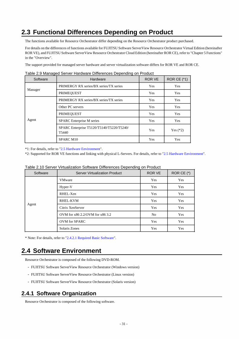
2.3 Functional Differences Depending on ProductThe functions available for Resource Orchestrator differ depending on the Resource Orchestrator product purchased.
For details on the differences of functions available for FUJITSU Software ServerView Resource Orchestrator Virtual Edition (hereinafterROR VE), and FUJITSU Software ServerView Resource Orchestrator Cloud Edition (hereinafter ROR CE), refer to "Chapter 5 Functions"in the "Overview".
The support provided for managed server hardware and server virtualization software differs for ROR VE and ROR CE.
Table 2.9 Managed Server Hardware Differences Depending on Product
Software Hardware ROR VE ROR CE (*1)
ManagerPRIMERGY RX series/BX series/TX series Yes Yes
PRIMEQUEST Yes Yes
Agent
PRIMERGY RX series/BX series/TX series Yes Yes
Other PC servers Yes Yes
PRIMEQUEST Yes Yes
SPARC Enterprise M series Yes Yes
SPARC Enterprise T5120/T5140/T5220/T5240/T5440
Yes Yes (*2)
SPARC M10 Yes Yes
*1: For details, refer to "2.5 Hardware Environment".*2: Supported for ROR VE functions and linking with physical L-Servers. For details, refer to "2.5 Hardware Environment".
Table 2.10 Server Virtualization Software Differences Depending on Product
Software Server Virtualization Product ROR VE ROR CE (*)
Agent
VMware Yes Yes
Hyper-V Yes Yes
RHEL-Xen Yes Yes
RHEL-KVM Yes Yes
Citrix XenServer Yes Yes
OVM for x86 2.2/OVM for x86 3.2 No Yes
OVM for SPARC Yes Yes
Solaris Zones Yes Yes
* Note: For details, refer to "2.4.2.1 Required Basic Software".
2.4 Software EnvironmentResource Orchestrator is composed of the following DVD-ROM.
- FUJITSU Software ServerView Resource Orchestrator (Windows version)
- FUJITSU Software ServerView Resource Orchestrator (Linux version)
- FUJITSU Software ServerView Resource Orchestrator (Solaris version)
2.4.1 Software OrganizationResource Orchestrator is composed of the following software.
- 31 -
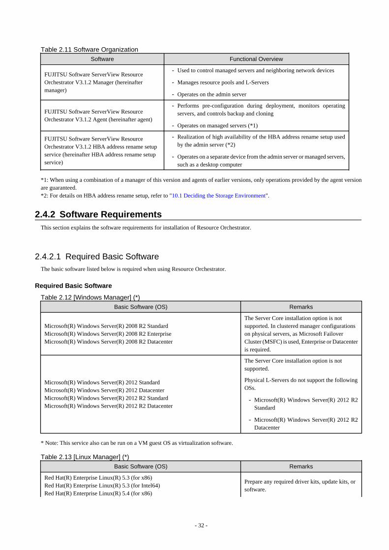
Table 2.11 Software OrganizationSoftware Functional Overview
FUJITSU Software ServerView ResourceOrchestrator V3.1.2 Manager (hereinaftermanager)
- Used to control managed servers and neighboring network devices
- Manages resource pools and L-Servers
- Operates on the admin server
FUJITSU Software ServerView ResourceOrchestrator V3.1.2 Agent (hereinafter agent)
- Performs pre-configuration during deployment, monitors operatingservers, and controls backup and cloning
- Operates on managed servers (*1)
FUJITSU Software ServerView ResourceOrchestrator V3.1.2 HBA address rename setupservice (hereinafter HBA address rename setupservice)
- Realization of high availability of the HBA address rename setup usedby the admin server (*2)
- Operates on a separate device from the admin server or managed servers,such as a desktop computer
*1: When using a combination of a manager of this version and agents of earlier versions, only operations provided by the agent versionare guaranteed.*2: For details on HBA address rename setup, refer to "10.1 Deciding the Storage Environment".
2.4.2 Software RequirementsThis section explains the software requirements for installation of Resource Orchestrator.
2.4.2.1 Required Basic SoftwareThe basic software listed below is required when using Resource Orchestrator.
Required Basic Software
Table 2.12 [Windows Manager] (*)
Basic Software (OS) Remarks
Microsoft(R) Windows Server(R) 2008 R2 StandardMicrosoft(R) Windows Server(R) 2008 R2 EnterpriseMicrosoft(R) Windows Server(R) 2008 R2 Datacenter
The Server Core installation option is notsupported. In clustered manager configurationson physical servers, as Microsoft FailoverCluster (MSFC) is used, Enterprise or Datacenteris required.
Microsoft(R) Windows Server(R) 2012 StandardMicrosoft(R) Windows Server(R) 2012 DatacenterMicrosoft(R) Windows Server(R) 2012 R2 StandardMicrosoft(R) Windows Server(R) 2012 R2 Datacenter
The Server Core installation option is notsupported.
Physical L-Servers do not support the followingOSs.
- Microsoft(R) Windows Server(R) 2012 R2Standard
- Microsoft(R) Windows Server(R) 2012 R2Datacenter
* Note: This service also can be run on a VM guest OS as virtualization software.
Table 2.13 [Linux Manager] (*)
Basic Software (OS) Remarks
Red Hat(R) Enterprise Linux(R) 5.3 (for x86)Red Hat(R) Enterprise Linux(R) 5.3 (for Intel64)Red Hat(R) Enterprise Linux(R) 5.4 (for x86)
Prepare any required driver kits, update kits, orsoftware.
- 32 -
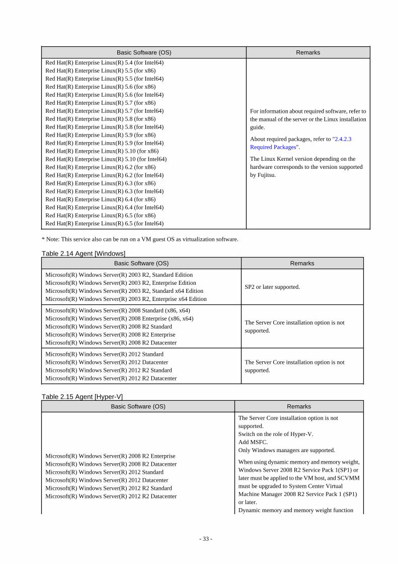
Basic Software (OS) Remarks
Red Hat(R) Enterprise Linux(R) 5.4 (for Intel64)Red Hat(R) Enterprise Linux(R) 5.5 (for x86)Red Hat(R) Enterprise Linux(R) 5.5 (for Intel64)Red Hat(R) Enterprise Linux(R) 5.6 (for x86)Red Hat(R) Enterprise Linux(R) 5.6 (for Intel64)Red Hat(R) Enterprise Linux(R) 5.7 (for x86)Red Hat(R) Enterprise Linux(R) 5.7 (for Intel64)Red Hat(R) Enterprise Linux(R) 5.8 (for x86)Red Hat(R) Enterprise Linux(R) 5.8 (for Intel64)Red Hat(R) Enterprise Linux(R) 5.9 (for x86)Red Hat(R) Enterprise Linux(R) 5.9 (for Intel64)Red Hat(R) Enterprise Linux(R) 5.10 (for x86)Red Hat(R) Enterprise Linux(R) 5.10 (for Intel64)Red Hat(R) Enterprise Linux(R) 6.2 (for x86)Red Hat(R) Enterprise Linux(R) 6.2 (for Intel64)Red Hat(R) Enterprise Linux(R) 6.3 (for x86)Red Hat(R) Enterprise Linux(R) 6.3 (for Intel64)Red Hat(R) Enterprise Linux(R) 6.4 (for x86)Red Hat(R) Enterprise Linux(R) 6.4 (for Intel64)Red Hat(R) Enterprise Linux(R) 6.5 (for x86)Red Hat(R) Enterprise Linux(R) 6.5 (for Intel64)
For information about required software, refer tothe manual of the server or the Linux installationguide.
About required packages, refer to "2.4.2.3Required Packages".
The Linux Kernel version depending on thehardware corresponds to the version supportedby Fujitsu.
* Note: This service also can be run on a VM guest OS as virtualization software.
Table 2.14 Agent [Windows]
Basic Software (OS) Remarks
Microsoft(R) Windows Server(R) 2003 R2, Standard EditionMicrosoft(R) Windows Server(R) 2003 R2, Enterprise EditionMicrosoft(R) Windows Server(R) 2003 R2, Standard x64 EditionMicrosoft(R) Windows Server(R) 2003 R2, Enterprise x64 Edition
SP2 or later supported.
Microsoft(R) Windows Server(R) 2008 Standard (x86, x64)Microsoft(R) Windows Server(R) 2008 Enterprise (x86, x64)Microsoft(R) Windows Server(R) 2008 R2 StandardMicrosoft(R) Windows Server(R) 2008 R2 EnterpriseMicrosoft(R) Windows Server(R) 2008 R2 Datacenter
The Server Core installation option is notsupported.
Microsoft(R) Windows Server(R) 2012 StandardMicrosoft(R) Windows Server(R) 2012 DatacenterMicrosoft(R) Windows Server(R) 2012 R2 StandardMicrosoft(R) Windows Server(R) 2012 R2 Datacenter
The Server Core installation option is notsupported.
Table 2.15 Agent [Hyper-V]
Basic Software (OS) Remarks
Microsoft(R) Windows Server(R) 2008 R2 EnterpriseMicrosoft(R) Windows Server(R) 2008 R2 DatacenterMicrosoft(R) Windows Server(R) 2012 StandardMicrosoft(R) Windows Server(R) 2012 DatacenterMicrosoft(R) Windows Server(R) 2012 R2 StandardMicrosoft(R) Windows Server(R) 2012 R2 Datacenter
The Server Core installation option is notsupported.Switch on the role of Hyper-V.Add MSFC.Only Windows managers are supported.
When using dynamic memory and memory weight,Windows Server 2008 R2 Service Pack 1(SP1) orlater must be applied to the VM host, and SCVMMmust be upgraded to System Center VirtualMachine Manager 2008 R2 Service Pack 1 (SP1)or later.Dynamic memory and memory weight function
- 33 -
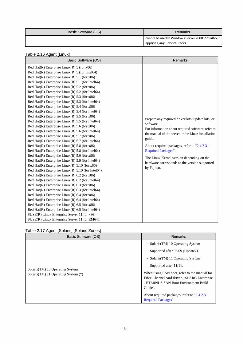
Basic Software (OS) Remarks
cannot be used in Windows Server 2008 R2 withoutapplying any Service Packs.
Table 2.16 Agent [Linux]
Basic Software (OS) Remarks
Red Hat(R) Enterprise Linux(R) 5 (for x86)Red Hat(R) Enterprise Linux(R) 5 (for Intel64)Red Hat(R) Enterprise Linux(R) 5.1 (for x86)Red Hat(R) Enterprise Linux(R) 5.1 (for Intel64)Red Hat(R) Enterprise Linux(R) 5.2 (for x86)Red Hat(R) Enterprise Linux(R) 5.2 (for Intel64)Red Hat(R) Enterprise Linux(R) 5.3 (for x86)Red Hat(R) Enterprise Linux(R) 5.3 (for Intel64)Red Hat(R) Enterprise Linux(R) 5.4 (for x86)Red Hat(R) Enterprise Linux(R) 5.4 (for Intel64)Red Hat(R) Enterprise Linux(R) 5.5 (for x86)Red Hat(R) Enterprise Linux(R) 5.5 (for Intel64)Red Hat(R) Enterprise Linux(R) 5.6 (for x86)Red Hat(R) Enterprise Linux(R) 5.6 (for Intel64)Red Hat(R) Enterprise Linux(R) 5.7 (for x86)Red Hat(R) Enterprise Linux(R) 5.7 (for Intel64)Red Hat(R) Enterprise Linux(R) 5.8 (for x86)Red Hat(R) Enterprise Linux(R) 5.8 (for Intel64)Red Hat(R) Enterprise Linux(R) 5.9 (for x86)Red Hat(R) Enterprise Linux(R) 5.9 (for Intel64)Red Hat(R) Enterprise Linux(R) 5.10 (for x86)Red Hat(R) Enterprise Linux(R) 5.10 (for Intel64)Red Hat(R) Enterprise Linux(R) 6.2 (for x86)Red Hat(R) Enterprise Linux(R) 6.2 (for Intel64)Red Hat(R) Enterprise Linux(R) 6.3 (for x86)Red Hat(R) Enterprise Linux(R) 6.3 (for Intel64)Red Hat(R) Enterprise Linux(R) 6.4 (for x86)Red Hat(R) Enterprise Linux(R) 6.4 (for Intel64)Red Hat(R) Enterprise Linux(R) 6.5 (for x86)Red Hat(R) Enterprise Linux(R) 6.5 (for Intel64)SUSE(R) Linux Enterprise Server 11 for x86SUSE(R) Linux Enterprise Server 11 for EM64T
Prepare any required driver kits, update kits, orsoftware.For information about required software, refer tothe manual of the server or the Linux installationguide.
About required packages, refer to "2.4.2.3Required Packages".
The Linux Kernel version depending on thehardware corresponds to the version supportedby Fujitsu.
Table 2.17 Agent [Solaris] [Solaris Zones]
Basic Software (OS) Remarks
Solaris(TM) 10 Operating SystemSolaris(TM) 11 Operating System (*)
- Solaris(TM) 10 Operating System
Supported after 05/09 (Update7).
- Solaris(TM) 11 Operating System
Supported after 11/11.
When using SAN boot, refer to the manual forFibre Channel card driver, "SPARC Enterprise- ETERNUS SAN Boot Environment BuildGuide".
About required packages, refer to "2.4.2.3Required Packages"
- 34 -
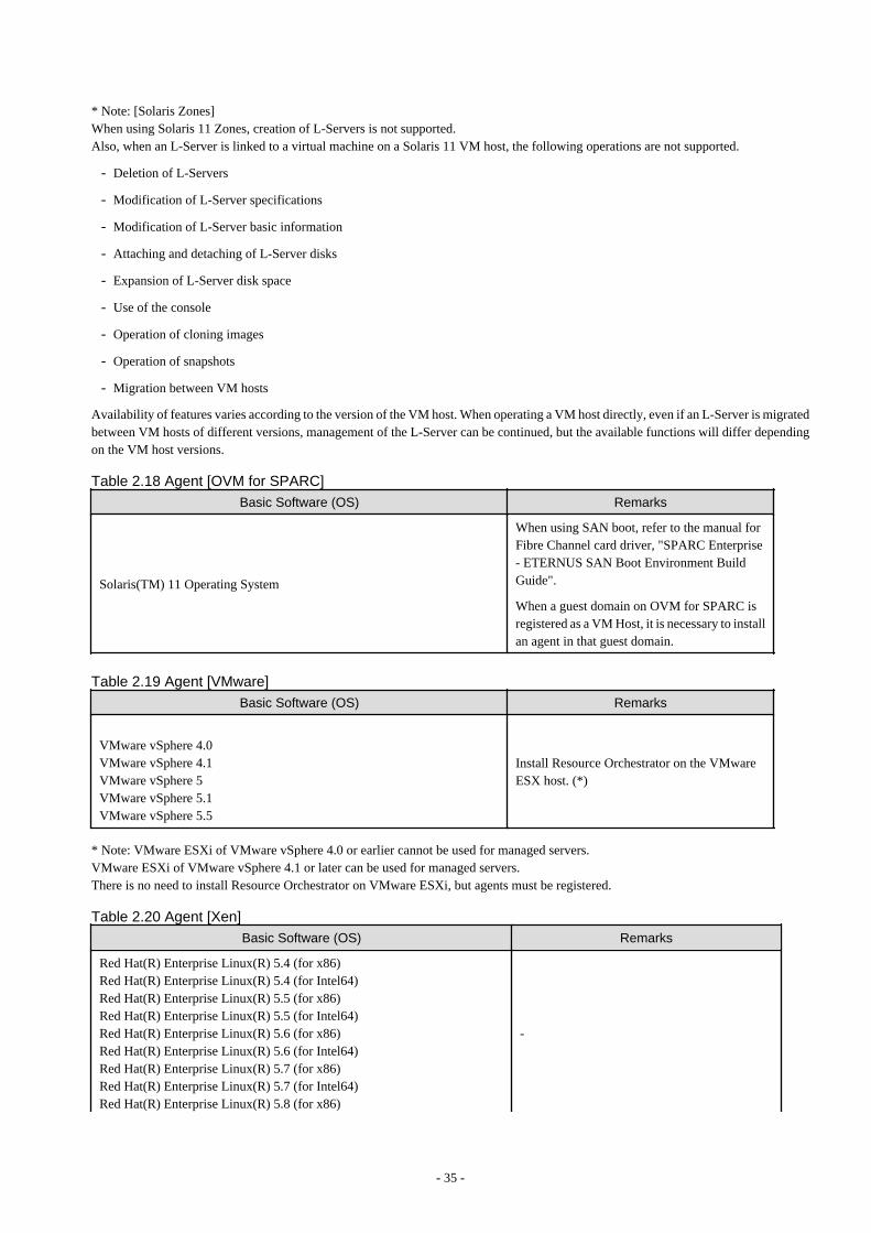
* Note: [Solaris Zones]When using Solaris 11 Zones, creation of L-Servers is not supported.Also, when an L-Server is linked to a virtual machine on a Solaris 11 VM host, the following operations are not supported.
- Deletion of L-Servers
- Modification of L-Server specifications
- Modification of L-Server basic information
- Attaching and detaching of L-Server disks
- Expansion of L-Server disk space
- Use of the console
- Operation of cloning images
- Operation of snapshots
- Migration between VM hosts
Availability of features varies according to the version of the VM host. When operating a VM host directly, even if an L-Server is migratedbetween VM hosts of different versions, management of the L-Server can be continued, but the available functions will differ dependingon the VM host versions.
Table 2.18 Agent [OVM for SPARC]
Basic Software (OS) Remarks
Solaris(TM) 11 Operating System
When using SAN boot, refer to the manual forFibre Channel card driver, "SPARC Enterprise- ETERNUS SAN Boot Environment BuildGuide".
When a guest domain on OVM for SPARC isregistered as a VM Host, it is necessary to installan agent in that guest domain.
Table 2.19 Agent [VMware]
Basic Software (OS) Remarks
VMware vSphere 4.0VMware vSphere 4.1VMware vSphere 5VMware vSphere 5.1VMware vSphere 5.5
Install Resource Orchestrator on the VMwareESX host. (*)
* Note: VMware ESXi of VMware vSphere 4.0 or earlier cannot be used for managed servers.VMware ESXi of VMware vSphere 4.1 or later can be used for managed servers.There is no need to install Resource Orchestrator on VMware ESXi, but agents must be registered.
Table 2.20 Agent [Xen]
Basic Software (OS) Remarks
Red Hat(R) Enterprise Linux(R) 5.4 (for x86)Red Hat(R) Enterprise Linux(R) 5.4 (for Intel64)Red Hat(R) Enterprise Linux(R) 5.5 (for x86)Red Hat(R) Enterprise Linux(R) 5.5 (for Intel64)Red Hat(R) Enterprise Linux(R) 5.6 (for x86)Red Hat(R) Enterprise Linux(R) 5.6 (for Intel64)Red Hat(R) Enterprise Linux(R) 5.7 (for x86)Red Hat(R) Enterprise Linux(R) 5.7 (for Intel64)Red Hat(R) Enterprise Linux(R) 5.8 (for x86)
-
- 35 -
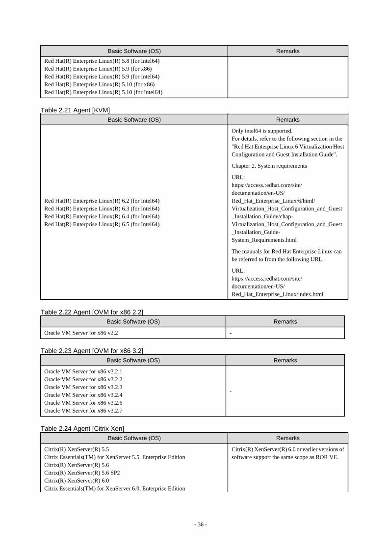
Basic Software (OS) Remarks
Red Hat(R) Enterprise Linux(R) 5.8 (for Intel64)Red Hat(R) Enterprise Linux(R) 5.9 (for x86)Red Hat(R) Enterprise Linux(R) 5.9 (for Intel64)Red Hat(R) Enterprise Linux(R) 5.10 (for x86)Red Hat(R) Enterprise Linux(R) 5.10 (for Intel64)
Table 2.21 Agent [KVM]
Basic Software (OS) Remarks
Red Hat(R) Enterprise Linux(R) 6.2 (for Intel64)Red Hat(R) Enterprise Linux(R) 6.3 (for Intel64)Red Hat(R) Enterprise Linux(R) 6.4 (for Intel64)Red Hat(R) Enterprise Linux(R) 6.5 (for Intel64)
Only intel64 is supported.For details, refer to the following section in the"Red Hat Enterprise Linux 6 Virtualization HostConfiguration and Guest Installation Guide".
Chapter 2. System requirements
URL:https://access.redhat.com/site/documentation/en-US/Red_Hat_Enterprise_Linux/6/html/Virtualization_Host_Configuration_and_Guest_Installation_Guide/chap-Virtualization_Host_Configuration_and_Guest_Installation_Guide-System_Requirements.html
The manuals for Red Hat Enterprise Linux canbe referred to from the following URL.
URL:https://access.redhat.com/site/documentation/en-US/Red_Hat_Enterprise_Linux/index.html
Table 2.22 Agent [OVM for x86 2.2]
Basic Software (OS) Remarks
Oracle VM Server for x86 v2.2 -
Table 2.23 Agent [OVM for x86 3.2]
Basic Software (OS) Remarks
Oracle VM Server for x86 v3.2.1Oracle VM Server for x86 v3.2.2Oracle VM Server for x86 v3.2.3Oracle VM Server for x86 v3.2.4Oracle VM Server for x86 v3.2.6Oracle VM Server for x86 v3.2.7
-
Table 2.24 Agent [Citrix Xen]
Basic Software (OS) Remarks
Citrix(R) XenServer(R) 5.5Citrix Essentials(TM) for XenServer 5.5, Enterprise EditionCitrix(R) XenServer(R) 5.6Citrix(R) XenServer(R) 5.6 SP2Citrix(R) XenServer(R) 6.0Citrix Essentials(TM) for XenServer 6.0, Enterprise Edition
Citrix(R) XenServer(R) 6.0 or earlier versions ofsoftware support the same scope as ROR VE.
- 36 -
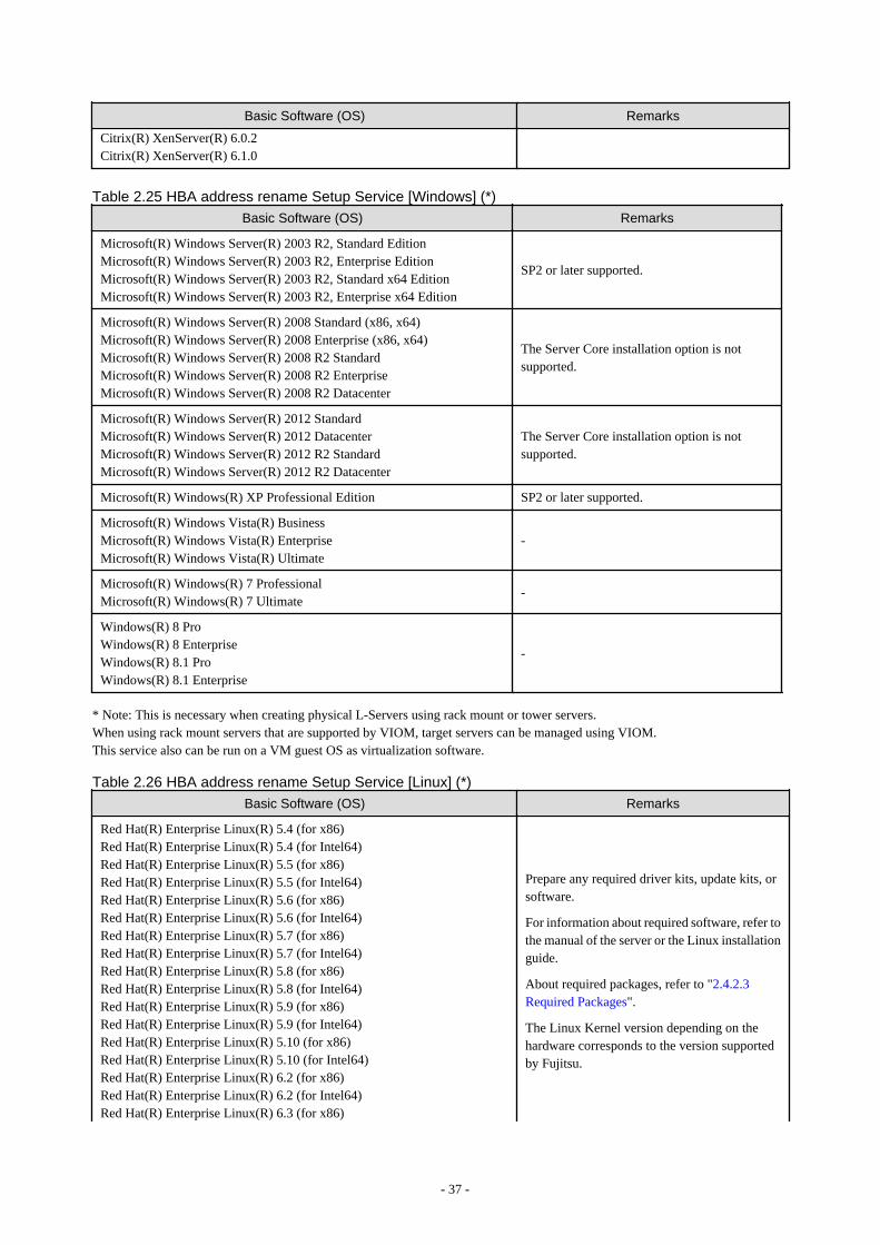
Basic Software (OS) Remarks
Citrix(R) XenServer(R) 6.0.2Citrix(R) XenServer(R) 6.1.0
Table 2.25 HBA address rename Setup Service [Windows] (*)
Basic Software (OS) Remarks
Microsoft(R) Windows Server(R) 2003 R2, Standard EditionMicrosoft(R) Windows Server(R) 2003 R2, Enterprise EditionMicrosoft(R) Windows Server(R) 2003 R2, Standard x64 EditionMicrosoft(R) Windows Server(R) 2003 R2, Enterprise x64 Edition
SP2 or later supported.
Microsoft(R) Windows Server(R) 2008 Standard (x86, x64)Microsoft(R) Windows Server(R) 2008 Enterprise (x86, x64)Microsoft(R) Windows Server(R) 2008 R2 StandardMicrosoft(R) Windows Server(R) 2008 R2 EnterpriseMicrosoft(R) Windows Server(R) 2008 R2 Datacenter
The Server Core installation option is notsupported.
Microsoft(R) Windows Server(R) 2012 StandardMicrosoft(R) Windows Server(R) 2012 DatacenterMicrosoft(R) Windows Server(R) 2012 R2 StandardMicrosoft(R) Windows Server(R) 2012 R2 Datacenter
The Server Core installation option is notsupported.
Microsoft(R) Windows(R) XP Professional Edition SP2 or later supported.
Microsoft(R) Windows Vista(R) BusinessMicrosoft(R) Windows Vista(R) EnterpriseMicrosoft(R) Windows Vista(R) Ultimate
-
Microsoft(R) Windows(R) 7 ProfessionalMicrosoft(R) Windows(R) 7 Ultimate
-
Windows(R) 8 ProWindows(R) 8 EnterpriseWindows(R) 8.1 ProWindows(R) 8.1 Enterprise
-
* Note: This is necessary when creating physical L-Servers using rack mount or tower servers.When using rack mount servers that are supported by VIOM, target servers can be managed using VIOM.This service also can be run on a VM guest OS as virtualization software.
Table 2.26 HBA address rename Setup Service [Linux] (*)
Basic Software (OS) Remarks
Red Hat(R) Enterprise Linux(R) 5.4 (for x86)Red Hat(R) Enterprise Linux(R) 5.4 (for Intel64)Red Hat(R) Enterprise Linux(R) 5.5 (for x86)Red Hat(R) Enterprise Linux(R) 5.5 (for Intel64)Red Hat(R) Enterprise Linux(R) 5.6 (for x86)Red Hat(R) Enterprise Linux(R) 5.6 (for Intel64)Red Hat(R) Enterprise Linux(R) 5.7 (for x86)Red Hat(R) Enterprise Linux(R) 5.7 (for Intel64)Red Hat(R) Enterprise Linux(R) 5.8 (for x86)Red Hat(R) Enterprise Linux(R) 5.8 (for Intel64)Red Hat(R) Enterprise Linux(R) 5.9 (for x86)Red Hat(R) Enterprise Linux(R) 5.9 (for Intel64)Red Hat(R) Enterprise Linux(R) 5.10 (for x86)Red Hat(R) Enterprise Linux(R) 5.10 (for Intel64)Red Hat(R) Enterprise Linux(R) 6.2 (for x86)Red Hat(R) Enterprise Linux(R) 6.2 (for Intel64)Red Hat(R) Enterprise Linux(R) 6.3 (for x86)
Prepare any required driver kits, update kits, orsoftware.
For information about required software, refer tothe manual of the server or the Linux installationguide.
About required packages, refer to "2.4.2.3Required Packages".
The Linux Kernel version depending on thehardware corresponds to the version supportedby Fujitsu.
- 37 -

Basic Software (OS) Remarks
Red Hat(R) Enterprise Linux(R) 6.3 (for Intel64)Red Hat(R) Enterprise Linux(R) 6.4 (for x86)Red Hat(R) Enterprise Linux(R) 6.4 (for Intel64)Red Hat(R) Enterprise Linux(R) 6.5 (for x86)Red Hat(R) Enterprise Linux(R) 6.5 (for Intel64)
* Note: This is necessary when creating physical L-Servers using rack mount or tower servers.When using rack mount servers that are supported by VIOM, target servers can be managed using VIOM.This service also can be run on a VM guest OS as virtualization software.
Note
[VMware]The free version of VMware ESXi cannot be used for managed servers.When using VMware ESXi for managed servers, purchase the appropriate license.
Installation will fail when a Resource Orchestrator agent is installed on an unsupported OS.
[Hyper-V]When using Hyper-V on managed servers, the only supported OS of the admin server is Windows.
[Xen]When using RHEL5-Xen on managed servers, the only supported OS of the admin server is Linux.
Certain functions of server virtualization software cannot be used when that software is managed using Resource Orchestrator.
[Hyper-V]VMware ESX and Citrix(R) XenServer(TM) can be managed by SCVMM, but only VM hosts for Hyper-V can be managed when usingSCVMM in Resource Orchestrator.
Table 2.27 List of Functions Not Supported by Resource Orchestrator
Server Virtualization Software Function that Is not Supported
VMware vSphere 4.0VMware vSphere 4.1VMware vSphere 5VMware vSphere 5.1VMware vSphere 5.5
Cisco Nexus 1000V virtual switch
VMware vSphere 5.5 vSphere Flash Read Cache
Microsoft(R) System Center Virtual Machine Manager 2008 R2Microsoft(R) System Center 2012 Virtual Machine ManagerMicrosoft(R) System Center 2012 R2 Virtual Machine Manager
- Movement of storage areas
- Movement changing the virtual machine storagedestination
- Saving in the virtual machine library
Oracle VM Manager Template
Windows Server 2012Windows Server 2012 R2
Hyper-V Replica
Note
- If an L-Server is created with a specified Windows image, when deploying the image use Sysprep, provided by Microsoft, toreconfigure the properties unique to the server. By executing Sysprep, the user information and OS setting information are reset.For details on Sysprep, refer to the information provided by Microsoft.
- 38 -
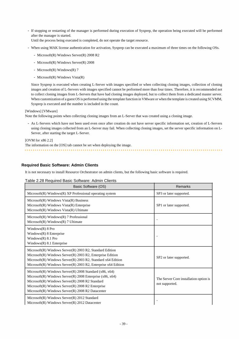
- If stopping or restarting of the manager is performed during execution of Sysprep, the operation being executed will be performedafter the manager is started.Until the process being executed is completed, do not operate the target resource.
- When using MAK license authentication for activation, Sysprep can be executed a maximum of three times on the following OSs.
- Microsoft(R) Windows Server(R) 2008 R2
- Microsoft(R) Windows Server(R) 2008
- Microsoft(R) Windows(R) 7
- Microsoft(R) Windows Vista(R)
Since Sysprep is executed when creating L-Server with images specified or when collecting cloning images, collection of cloningimages and creation of L-Servers with images specified cannot be performed more than four times. Therefore, it is recommended notto collect cloning images from L-Servers that have had cloning images deployed, but to collect them from a dedicated master server.When customization of a guest OS is performed using the template function in VMware or when the template is created using SCVMM,Sysprep is executed and the number is included in the count.
[Windows] [VMware]Note the following points when collecting cloning images from an L-Server that was created using a cloning image.
- As L-Servers which have not been used even once after creation do not have server specific information set, creation of L-Serversusing cloning images collected from an L-Server may fail. When collecting cloning images, set the server specific information on L-Server, after starting the target L-Server.
[OVM for x86 2.2]The information on the [OS] tab cannot be set when deploying the image.
Required Basic Software: Admin Clients
It is not necessary to install Resource Orchestrator on admin clients, but the following basic software is required.
Table 2.28 Required Basic Software: Admin Clients
Basic Software (OS) Remarks
Microsoft(R) Windows(R) XP Professional operating system SP3 or later supported.
Microsoft(R) Windows Vista(R) BusinessMicrosoft(R) Windows Vista(R) EnterpriseMicrosoft(R) Windows Vista(R) Ultimate
SP1 or later supported.
Microsoft(R) Windows(R) 7 ProfessionalMicrosoft(R) Windows(R) 7 Ultimate
-
Windows(R) 8 ProWindows(R) 8 EnterpriseWindows(R) 8.1 ProWindows(R) 8.1 Enterprise
-
Microsoft(R) Windows Server(R) 2003 R2, Standard EditionMicrosoft(R) Windows Server(R) 2003 R2, Enterprise EditionMicrosoft(R) Windows Server(R) 2003 R2, Standard x64 EditionMicrosoft(R) Windows Server(R) 2003 R2, Enterprise x64 Edition
SP2 or later supported.
Microsoft(R) Windows Server(R) 2008 Standard (x86, x64)Microsoft(R) Windows Server(R) 2008 Enterprise (x86, x64)Microsoft(R) Windows Server(R) 2008 R2 StandardMicrosoft(R) Windows Server(R) 2008 R2 EnterpriseMicrosoft(R) Windows Server(R) 2008 R2 Datacenter
The Server Core installation option isnot supported.
Microsoft(R) Windows Server(R) 2012 StandardMicrosoft(R) Windows Server(R) 2012 Datacenter
-
- 39 -
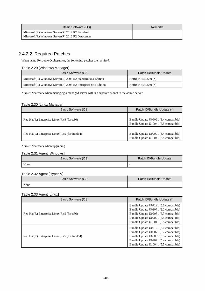
Basic Software (OS) Remarks
Microsoft(R) Windows Server(R) 2012 R2 StandardMicrosoft(R) Windows Server(R) 2012 R2 Datacenter
2.4.2.2 Required PatchesWhen using Resource Orchestrator, the following patches are required.
Table 2.29 [Windows Manager]
Basic Software (OS) Patch ID/Bundle Update
Microsoft(R) Windows Server(R) 2003 R2 Standard x64 Edition Hotfix KB942589 (*)
Microsoft(R) Windows Server(R) 2003 R2 Enterprise x64 Edition Hotfix KB942589 (*)
* Note: Necessary when managing a managed server within a separate subnet to the admin server.
Table 2.30 [Linux Manager]
Basic Software (OS) Patch ID/Bundle Update (*)
Red Hat(R) Enterprise Linux(R) 5 (for x86) Bundle Update U09091 (5.4 compatible)Bundle Update U10041 (5.5 compatible)
Red Hat(R) Enterprise Linux(R) 5 (for Intel64) Bundle Update U09091 (5.4 compatible)Bundle Update U10041 (5.5 compatible)
* Note: Necessary when upgrading.
Table 2.31 Agent [Windows]
Basic Software (OS) Patch ID/Bundle Update
None -
Table 2.32 Agent [Hyper-V]
Basic Software (OS) Patch ID/Bundle Update
None -
Table 2.33 Agent [Linux]
Basic Software (OS) Patch ID/Bundle Update (*)
Red Hat(R) Enterprise Linux(R) 5 (for x86)
Bundle Update U07121 (5.1 compatible)Bundle Update U08071 (5.2 compatible)Bundle Update U09031 (5.3 compatible)Bundle Update U09091 (5.4 compatible)Bundle Update U10041 (5.5 compatible)
Red Hat(R) Enterprise Linux(R) 5 (for Intel64)
Bundle Update U07121 (5.1 compatible)Bundle Update U08071 (5.2 compatible)Bundle Update U09031 (5.3 compatible)Bundle Update U09091 (5.4 compatible)Bundle Update U10041 (5.5 compatible)
- 40 -
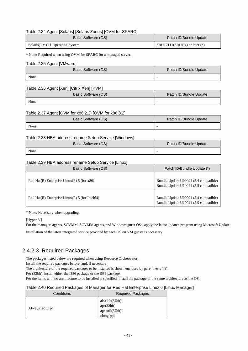
Table 2.34 Agent [Solaris] [Solaris Zones] [OVM for SPARC]Basic Software (OS) Patch ID/Bundle Update
Solaris(TM) 11 Operating System SRU12111(SRU1.4) or later (*)
* Note: Required when using OVM for SPARC for a managed server.
Table 2.35 Agent [VMware]
Basic Software (OS) Patch ID/Bundle Update
None -
Table 2.36 Agent [Xen] [Citrix Xen] [KVM]
Basic Software (OS) Patch ID/Bundle Update
None -
Table 2.37 Agent [OVM for x86 2.2] [OVM for x86 3.2]
Basic Software (OS) Patch ID/Bundle Update
None -
Table 2.38 HBA address rename Setup Service [Windows]
Basic Software (OS) Patch ID/Bundle Update
None -
Table 2.39 HBA address rename Setup Service [Linux]
Basic Software (OS) Patch ID/Bundle Update (*)
Red Hat(R) Enterprise Linux(R) 5 (for x86) Bundle Update U09091 (5.4 compatible)Bundle Update U10041 (5.5 compatible)
Red Hat(R) Enterprise Linux(R) 5 (for Intel64) Bundle Update U09091 (5.4 compatible)Bundle Update U10041 (5.5 compatible)
* Note: Necessary when upgrading.
[Hyper-V]For the manager, agents, SCVMM, SCVMM agents, and Windows guest OSs, apply the latest updated program using Microsoft Update.
Installation of the latest integrated service provided by each OS on VM guests is necessary.
2.4.2.3 Required PackagesThe packages listed below are required when using Resource Orchestrator.Install the required packages beforehand, if necessary.The architecture of the required packages to be installed is shown enclosed by parenthesis "()".For (32bit), install either the i386 package or the i686 package.For the items with no architecture to be installed is specified, install the package of the same architecture as the OS.
Table 2.40 Required Packages of Manager for Red Hat Enterprise Linux 6 [Linux Manager]
Conditions Required Packages
Always required
alsa-lib(32bit)apr(32bit)apr-util(32bit)cloog-ppl
- 41 -
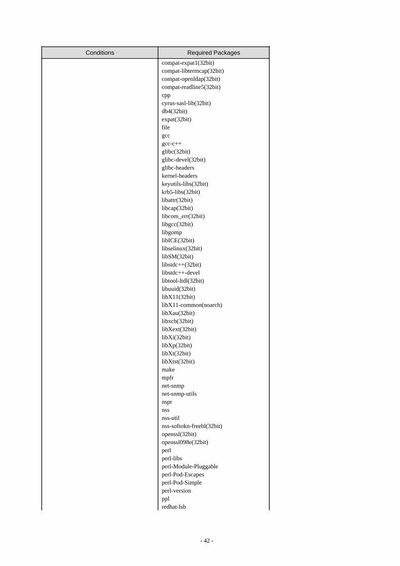
Conditions Required Packages
compat-expat1(32bit)compat-libtermcap(32bit)compat-openldap(32bit)compat-readline5(32bit)cppcyrus-sasl-lib(32bit)db4(32bit)expat(32bit)filegccgcc-c++glibc(32bit)glibc-devel(32bit)glibc-headerskernel-headerskeyutils-libs(32bit)krb5-libs(32bit)libattr(32bit)libcap(32bit)libcom_err(32bit)libgcc(32bit)libgomplibICE(32bit)libselinux(32bit)libSM(32bit)libstdc++(32bit)libstdc++-devellibtool-ltdl(32bit)libuuid(32bit)libX11(32bit)libX11-common(noarch)libXau(32bit)libxcb(32bit)libXext(32bit)libXi(32bit)libXp(32bit)libXt(32bit)libXtst(32bit)makempfrnet-snmpnet-snmp-utilsnsprnssnss-utilnss-softokn-freebl(32bit)openssl(32bit)openssl098e(32bit)perlperl-libsperl-Module-Pluggableperl-Pod-Escapesperl-Pod-Simpleperl-versionpplredhat-lsb
- 42 -

Conditions Required Packages
sqlite(32bit)sysstattcshunixODBC(32bit)X-Window (*)zlib(32bit)
Necessary when the OS architecture is Intel64
audit-libs(32bit)cracklib(32bit)elfutils-libelf(32bit)libxml2(32bit)ncurses-libs(32bit)pam(32bit)readline(32bit)
Necessary when the OS architecture is x86gdb(32bit)ncursesstrace(32bit)
Necessary when managing a managed serverwithin a separate subnet to the admin server
openldap
* Note: Install an OS, specifying a package.
Table 2.41 Required Packages of Manager for Red Hat Enterprise Linux 5 [Linux Manager]
Conditions Required Packages
Always required
apr(32bit)apr-util(32bit)glibc(32bit)libtermcap(32bit)libxml2(32bit)libXp(32bit)libxslt(32bit)net-snmpnet-snmp-utilspostgresql-libs(32bit)readline(32bit)redhat-lsbsysstatX-Window (*)zlib(32bit)
Necessary when the OS architecture is Intel64 elfutils-libelf(32bit)
* Note: Install an OS, specifying a package.
Table 2.42 Required Packages of Agent for Red Hat Enterprise Linux 6 [Linux] [KVM]
Conditions Required Packages
Always required
alsa-lib(32bit)glibc(32bit)libgcc(32bit)libICE(32bit)libSM(32bit)libstdc++(32bit)libtool-ltdl(32bit)libuuid(32bit)
- 43 -
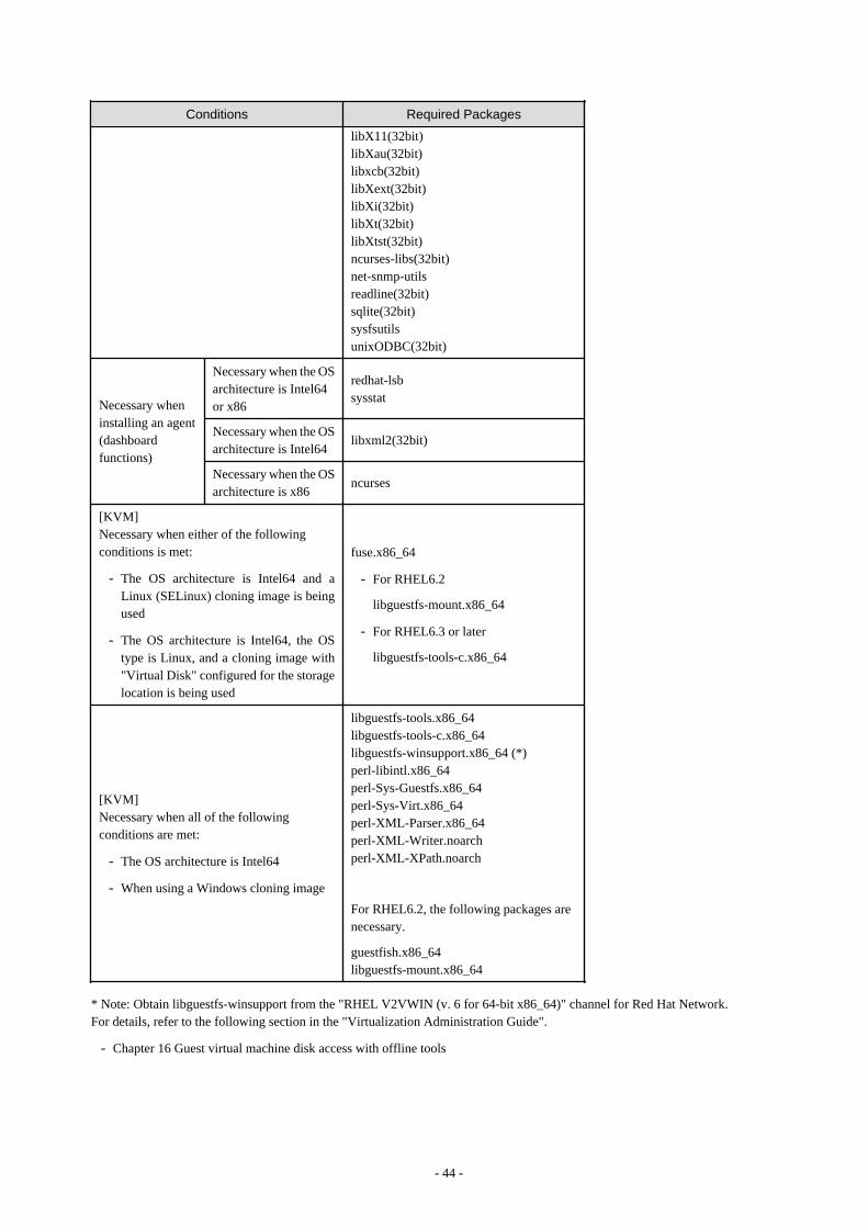
Conditions Required Packages
libX11(32bit)libXau(32bit)libxcb(32bit)libXext(32bit)libXi(32bit)libXt(32bit)libXtst(32bit)ncurses-libs(32bit)net-snmp-utilsreadline(32bit)sqlite(32bit)sysfsutilsunixODBC(32bit)
Necessary wheninstalling an agent(dashboardfunctions)
Necessary when the OSarchitecture is Intel64or x86
redhat-lsbsysstat
Necessary when the OSarchitecture is Intel64
libxml2(32bit)
Necessary when the OSarchitecture is x86
ncurses
[KVM]Necessary when either of the followingconditions is met:
- The OS architecture is Intel64 and aLinux (SELinux) cloning image is beingused
- The OS architecture is Intel64, the OStype is Linux, and a cloning image with"Virtual Disk" configured for the storagelocation is being used
fuse.x86_64
- For RHEL6.2
libguestfs-mount.x86_64
- For RHEL6.3 or later
libguestfs-tools-c.x86_64
[KVM]Necessary when all of the followingconditions are met:
- The OS architecture is Intel64
- When using a Windows cloning image
libguestfs-tools.x86_64libguestfs-tools-c.x86_64libguestfs-winsupport.x86_64 (*)perl-libintl.x86_64perl-Sys-Guestfs.x86_64perl-Sys-Virt.x86_64perl-XML-Parser.x86_64perl-XML-Writer.noarchperl-XML-XPath.noarch
For RHEL6.2, the following packages arenecessary.
guestfish.x86_64libguestfs-mount.x86_64
* Note: Obtain libguestfs-winsupport from the "RHEL V2VWIN (v. 6 for 64-bit x86_64)" channel for Red Hat Network.For details, refer to the following section in the "Virtualization Administration Guide".
- Chapter 16 Guest virtual machine disk access with offline tools
- 44 -
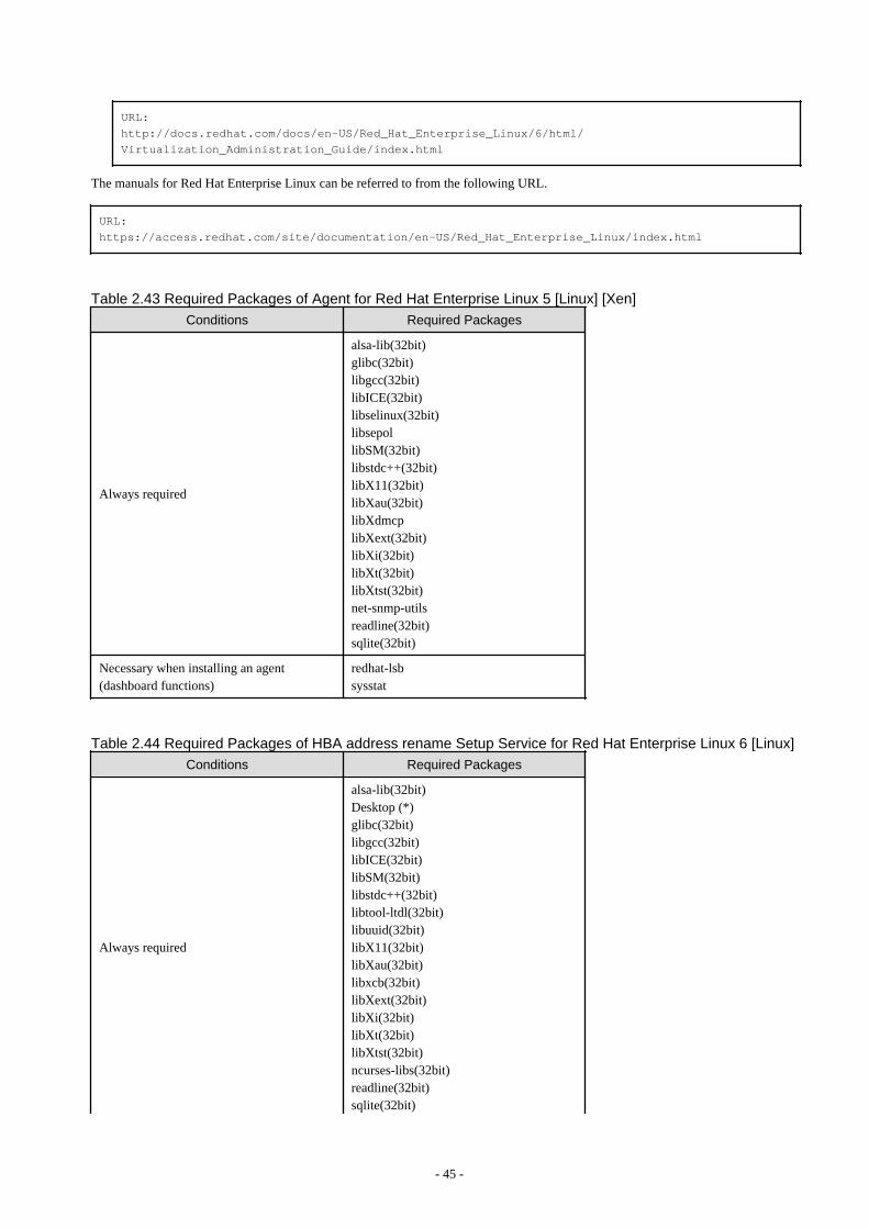
URL: http://docs.redhat.com/docs/en-US/Red_Hat_Enterprise_Linux/6/html/Virtualization_Administration_Guide/index.html
The manuals for Red Hat Enterprise Linux can be referred to from the following URL.
URL: https://access.redhat.com/site/documentation/en-US/Red_Hat_Enterprise_Linux/index.html
Table 2.43 Required Packages of Agent for Red Hat Enterprise Linux 5 [Linux] [Xen]
Conditions Required Packages
Always required
alsa-lib(32bit)glibc(32bit)libgcc(32bit)libICE(32bit)libselinux(32bit)libsepollibSM(32bit)libstdc++(32bit)libX11(32bit)libXau(32bit)libXdmcplibXext(32bit)libXi(32bit)libXt(32bit)libXtst(32bit)net-snmp-utilsreadline(32bit)sqlite(32bit)
Necessary when installing an agent(dashboard functions)
redhat-lsbsysstat
Table 2.44 Required Packages of HBA address rename Setup Service for Red Hat Enterprise Linux 6 [Linux]
Conditions Required Packages
Always required
alsa-lib(32bit)Desktop (*)glibc(32bit)libgcc(32bit)libICE(32bit)libSM(32bit)libstdc++(32bit)libtool-ltdl(32bit)libuuid(32bit)libX11(32bit)libXau(32bit)libxcb(32bit)libXext(32bit)libXi(32bit)libXt(32bit)libXtst(32bit)ncurses-libs(32bit)readline(32bit)sqlite(32bit)
- 45 -
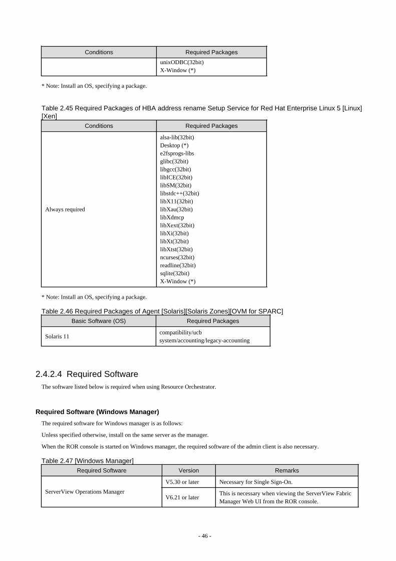
Conditions Required Packages
unixODBC(32bit)X-Window (*)
* Note: Install an OS, specifying a package.
Table 2.45 Required Packages of HBA address rename Setup Service for Red Hat Enterprise Linux 5 [Linux][Xen]
Conditions Required Packages
Always required
alsa-lib(32bit)Desktop (*)e2fsprogs-libsglibc(32bit)libgcc(32bit)libICE(32bit)libSM(32bit)libstdc++(32bit)libX11(32bit)libXau(32bit)libXdmcplibXext(32bit)libXi(32bit)libXt(32bit)libXtst(32bit)ncurses(32bit)readline(32bit)sqlite(32bit)X-Window (*)
* Note: Install an OS, specifying a package.
Table 2.46 Required Packages of Agent [Solaris][Solaris Zones][OVM for SPARC]
Basic Software (OS) Required Packages
Solaris 11compatibility/ucbsystem/accounting/legacy-accounting
2.4.2.4 Required SoftwareThe software listed below is required when using Resource Orchestrator.
Required Software (Windows Manager)
The required software for Windows manager is as follows:
Unless specified otherwise, install on the same server as the manager.
When the ROR console is started on Windows manager, the required software of the admin client is also necessary.
Table 2.47 [Windows Manager]
Required Software Version Remarks
ServerView Operations Manager
V5.30 or later Necessary for Single Sign-On.
V6.21 or laterThis is necessary when viewing the ServerView FabricManager Web UI from the ROR console.
- 46 -
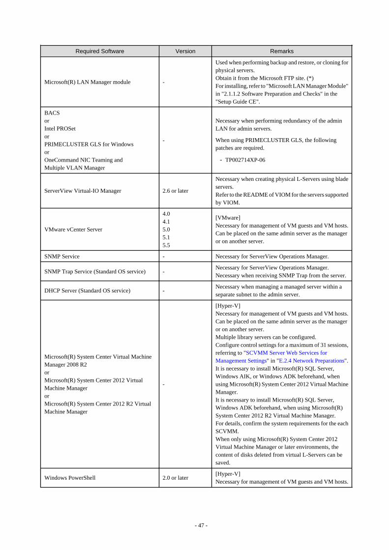
Required Software Version Remarks
Microsoft(R) LAN Manager module -
Used when performing backup and restore, or cloning forphysical servers.Obtain it from the Microsoft FTP site. (*)For installing, refer to "Microsoft LAN Manager Module"in "2.1.1.2 Software Preparation and Checks" in the"Setup Guide CE".
BACSorIntel PROSetorPRIMECLUSTER GLS for WindowsorOneCommand NIC Teaming andMultiple VLAN Manager
-
Necessary when performing redundancy of the adminLAN for admin servers.
When using PRIMECLUSTER GLS, the followingpatches are required.
- TP002714XP-06
ServerView Virtual-IO Manager 2.6 or later
Necessary when creating physical L-Servers using bladeservers.Refer to the README of VIOM for the servers supportedby VIOM.
VMware vCenter Server
4.04.15.05.15.5
[VMware]Necessary for management of VM guests and VM hosts.Can be placed on the same admin server as the manageror on another server.
SNMP Service - Necessary for ServerView Operations Manager.
SNMP Trap Service (Standard OS service) -Necessary for ServerView Operations Manager.Necessary when receiving SNMP Trap from the server.
DHCP Server (Standard OS service) -Necessary when managing a managed server within aseparate subnet to the admin server.
Microsoft(R) System Center Virtual MachineManager 2008 R2orMicrosoft(R) System Center 2012 VirtualMachine ManagerorMicrosoft(R) System Center 2012 R2 VirtualMachine Manager
-
[Hyper-V]Necessary for management of VM guests and VM hosts.Can be placed on the same admin server as the manageror on another server.Multiple library servers can be configured.Configure control settings for a maximum of 31 sessions,referring to "SCVMM Server Web Services forManagement Settings" in "E.2.4 Network Preparations".It is necessary to install Microsoft(R) SQL Server,Windows AIK, or Windows ADK beforehand, whenusing Microsoft(R) System Center 2012 Virtual MachineManager.It is necessary to install Microsoft(R) SQL Server,Windows ADK beforehand, when using Microsoft(R)System Center 2012 R2 Virtual Machine Manager.For details, confirm the system requirements for the eachSCVMM.When only using Microsoft(R) System Center 2012Virtual Machine Manager or later environments, thecontent of disks deleted from virtual L-Servers can besaved.
Windows PowerShell 2.0 or later[Hyper-V]Necessary for management of VM guests and VM hosts.
- 47 -
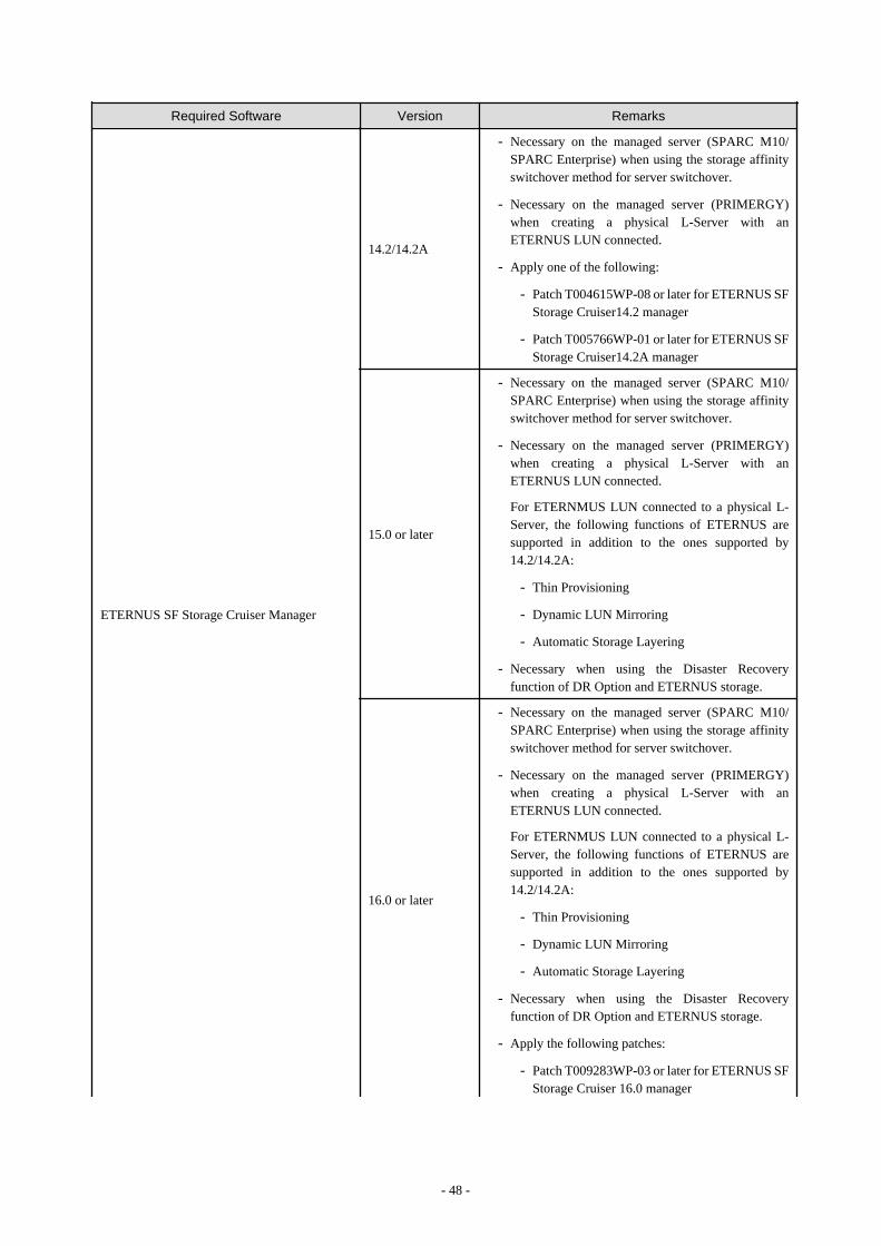
Required Software Version Remarks
ETERNUS SF Storage Cruiser Manager
14.2/14.2A
- Necessary on the managed server (SPARC M10/SPARC Enterprise) when using the storage affinityswitchover method for server switchover.
- Necessary on the managed server (PRIMERGY)when creating a physical L-Server with anETERNUS LUN connected.
- Apply one of the following:
- Patch T004615WP-08 or later for ETERNUS SFStorage Cruiser14.2 manager
- Patch T005766WP-01 or later for ETERNUS SFStorage Cruiser14.2A manager
15.0 or later
- Necessary on the managed server (SPARC M10/SPARC Enterprise) when using the storage affinityswitchover method for server switchover.
- Necessary on the managed server (PRIMERGY)when creating a physical L-Server with anETERNUS LUN connected.
For ETERNMUS LUN connected to a physical L-Server, the following functions of ETERNUS aresupported in addition to the ones supported by14.2/14.2A:
- Thin Provisioning
- Dynamic LUN Mirroring
- Automatic Storage Layering
- Necessary when using the Disaster Recoveryfunction of DR Option and ETERNUS storage.
16.0 or later
- Necessary on the managed server (SPARC M10/SPARC Enterprise) when using the storage affinityswitchover method for server switchover.
- Necessary on the managed server (PRIMERGY)when creating a physical L-Server with anETERNUS LUN connected.
For ETERNMUS LUN connected to a physical L-Server, the following functions of ETERNUS aresupported in addition to the ones supported by14.2/14.2A:
- Thin Provisioning
- Dynamic LUN Mirroring
- Automatic Storage Layering
- Necessary when using the Disaster Recoveryfunction of DR Option and ETERNUS storage.
- Apply the following patches:
- Patch T009283WP-03 or later for ETERNUS SFStorage Cruiser 16.0 manager
- 48 -

Required Software Version Remarks
- There are the following notes when ETERNUS SFStorage Cruiser manages ETERNUS DX200 S3/DX500 S3/DX600 S3 and ETERNUS SF StorageCruiser version is 16.1 or later.
- Please do not use the CA port that is the objectof pairing of CA ports of storage cluster functionby physical L-Server. For details on the methodof specifying the CA port used by physical L-Server, refer to "B.1.1 Creating Definition FilesCombining Ports of SAN Storage" in the "SetupGuide".
- Please do not connect managed server (SPARCM10/SPARC Enterprise) that uses the storageaffinity switchover method for server switchoverwith the CA port that is the object of pairing ofCA ports of storage cluster function.
- Please do not use the CA port that existingphysical L-Server or managed server (SPARCM10/SPARC Enterprise) that uses the storageaffinity switchover method for server switchoveruses by pairing of CA ports of storage clusterfunction.
ETERNUS SF AdvancedCopy Manager CopyControl Module
15.0 or later
- Necessary on managed servers (PRIMERGY) whencreating physical L-Servers with ETERNUS LUNsconnected and using the following ETERNUSfunctions on ETERNUS LUNs connected to physicalL-Servers:
- Dynamic LUN Mirroring
- Necessary when using the Disaster Recoveryfunction of DR Option and ETERNUS storage.
- Necessary when using high availability for storagechassis on physical L-Servers with ETERNUS LUNsconnected.
16.0 or later
- Necessary on managed servers (PRIMERGY) whencreating physical L-Servers with ETERNUS LUNsconnected and using the following ETERNUSfunctions on ETERNUS LUNs connected to physicalL-Servers:
- Dynamic LUN Mirroring
- Necessary when using the Disaster Recoveryfunction of DR Option and ETERNUS storage.
- Necessary when using high availability for storagechassis on physical L-Servers with ETERNUS LUNsconnected.
- Apply the following patches:
- Patch T009283WP-03 or later for ETERNUS SFAdvancedCopy Manager 16.0 manager
NavisecCLI 7.30 or laterNecessary when connecting an EMC CLARiiON or EMCVNX LUN to a physical L-Server.
- 49 -
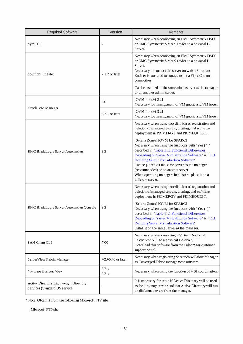
Required Software Version Remarks
SymCLI -Necessary when connecting an EMC Symmetrix DMXor EMC Symmetrix VMAX device to a physical L-Server.
Solutions Enabler 7.1.2 or later
Necessary when connecting an EMC Symmetrix DMXor EMC Symmetrix VMAX device to a physical L-Server.Necessary to connect the server on which SolutionsEnabler is operated to storage using a Fibre Channelconnection.
Can be installed on the same admin server as the manageror on another admin server.
Oracle VM Manager
3.0[OVM for x86 2.2]Necessary for management of VM guests and VM hosts.
3.2.1 or later[OVM for x86 3.2]Necessary for management of VM guests and VM hosts.
BMC BladeLogic Server Automation 8.3
Necessary when using coordination of registration anddeletion of managed servers, cloning, and softwaredeployment in PRIMERGY and PRIMEQUEST.
[Solaris Zones] [OVM for SPARC]Necessary when using the functions with "Yes (*)"described in "Table 11.1 Functional DifferencesDepending on Server Virtualization Software" in "11.1Deciding Server Virtualization Software".Can be placed on the same server as the manager(recommended) or on another server.When operating managers in clusters, place it on adifferent server.
BMC BladeLogic Server Automation Console 8.3
Necessary when using coordination of registration anddeletion of managed servers, cloning, and softwaredeployment in PRIMERGY and PRIMEQUEST.
[Solaris Zones] [OVM for SPARC]Necessary when using the functions with "Yes (*)"described in "Table 11.1 Functional DifferencesDepending on Server Virtualization Software" in "11.1Deciding Server Virtualization Software".Install it on the same server as the manager.
SAN Client CLI 7.00
Necessary when connecting a Virtual Device ofFalconStor NSS to a physical L-Server.Download this software from the FalconStor customersupport portal.
ServerView Fabric Manager V2.00.40 or laterNecessary when registering ServerView Fabric Manageras Converged Fabric management software.
VMware Horizon View5.2.x5.3.x
Necessary when using the function of VDI coordination.
Active Directory Lightweight DirectoryServices (Standard OS service)
-It is necessary for setup if Active Directory will be usedas the directory service and that Active Directory will runon different servers from the manager.
* Note: Obtain it from the following Microsoft FTP site.
Microsoft FTP site
- 50 -

URL: ftp://ftp.microsoft.com/bussys/clients/msclient/dsk3-1.exe
Required Software (Linux Manager)
Required Software for Linux Manager is as follows.
Unless specified otherwise, install on the same server as the manager.
Table 2.48 [Linux Manager]
Required Software Version Remarks
ServerView Operations Manager V5.30 or later Necessary for Single Sign-On.
Microsoft(R) LAN Manager module -
Necessary when using backup and restore, or cloning.Obtain it from the Microsoft FTP site. (*1)For installing, refer to "Microsoft LAN Manager Module"in "2.1.2.2 Software Preparation and Checks" in the "SetupGuide CE".
ServerView Virtual-IO Manager 2.6 or later
Necessary when creating physical L-Servers using bladeservers.Refer to the README of VIOM for the servers supportedby VIOM.
PRIMECLUSTER GLS -Necessary when performing redundancy of the adminLAN for admin servers.
VMware vCenter Server
4.04.15.05.15.5
[VMware]Necessary for management of VM guests and VM hosts.
ETERNUS SF Storage Cruiser Manager
14.2/14.2A
- Necessary on the managed server (SPARC M10/SPARC Enterprise) when using the storage affinityswitchover method for server switchover.
- Necessary on the managed server (PRIMERGY) whencreating a physical L-Server with an ETERNUS LUNconnected.
- Apply one of the following:
- Patch T004706LP-08 or later (x86),T004617LP-08 (Intel64) or later for ETERNUSSF Storage Cruiser14.2 manager
- Patch T005768LP-01 or later (x86),T005769LP-01 (Intel64) or later for ETERNUSSF Storage Cruiser14.2A manager
15.0 or later
- Necessary on the managed server (SPARC M10/SPARC Enterprise) when using the storage affinityswitchover method for server switchover.
- Necessary on the managed server (PRIMERGY) whencreating a physical L-Server with an ETERNUS LUNconnected.
For ETERNMUS LUN connected to a physical L-Server, the following functions of ETERNUS aresupported in addition to the ones supported by14.2/14.2A:
- 51 -

Required Software Version Remarks
- Thin Provisioning
- Dynamic LUN Mirroring
- Automatic Storage Layering
16.0 or later
- Necessary on the managed server (SPARC M10/SPARC Enterprise) when using the storage affinityswitchover method for server switchover.
- Necessary on the managed server (PRIMERGY) whencreating a physical L-Server with an ETERNUS LUNconnected.
For ETERNMUS LUN connected to a physical L-Server, the following functions of ETERNUS aresupported in addition to the ones supported by14.2/14.2A:
- Thin Provisioning
- Dynamic LUN Mirroring
- Automatic Storage Layering
- Apply the following patches:
- Patch T009286LP-03 or later for ETERNUS SFStorage Cruiser 16.0 manager
- There are the following notes when ETERNUS SFStorage Cruiser manages ETERNUS DX200 S3/DX500 S3/DX600 S3 and ETERNUS SF StorageCruiser version is 16.1 or later.
- Please do not use the CA port that is the object ofpairing of CA ports of storage cluster function byphysical L-Server. For details on the method ofspecifying the CA port used by physical L-Server,refer to "B.1.1 Creating Definition FilesCombining Ports of SAN Storage" in the "SetupGuide".
- Please do not connect managed server (SPARCM10/SPARC Enterprise) that uses the storageaffinity switchover method for server switchoverwith the CA port that is the object of pairing of CAports of storage cluster function.
- Please do not use the CA port that existing physicalL-Server or managed server (SPARC M10/SPARC Enterprise) that uses the storage affinityswitchover method for server switchover uses bypairing of CA ports of storage cluster function.
ETERNUS SF AdvancedCopy Manager CopyControl Module
15.0 or later
- Necessary on managed servers (PRIMERGY) whencreating physical L-Servers with ETERNUS LUNsconnected and using the following ETERNUSfunctions on ETERNUS LUNs connected to physicalL-Servers:
- Dynamic LUN Mirroring
- 52 -

Required Software Version Remarks
- Necessary when using high availability for storagechassis on physical L-Servers with ETERNUS LUNsconnected.
16.0 or later
- Necessary on managed servers (PRIMERGY) whencreating physical L-Servers with ETERNUS LUNsconnected and using the following ETERNUSfunctions on ETERNUS LUNs connected to physicalL-Servers:
- Dynamic LUN Mirroring
- Necessary when using high availability for storagechassis on physical L-Servers with ETERNUS LUNsconnected.
- Apply the following patches:
- Patch T009286LP-03 or later for ETERNUS SFAdvancedCopy Manager 16.0 manager
NavisecCLI 7.30 or laterNecessary when connecting an EMC CLARiiON or EMCVNX LUN to a physical L-Server.
SymCLI -Necessary when connecting an EMC Symmetrix DMX orEMC Symmetrix VMAX device to a physical L-Server.
Solutions Enabler 7.1.2 or later
Necessary when connecting an EMC Symmetrix DMX orEMC Symmetrix VMAX device to a physical L-Server.Necessary to connect the server on which SolutionsEnabler is operated to storage using a Fibre Channelconnection.
Can be installed on the same admin server as the manageror on another admin server.
Oracle VM Manager
3.0[OVM for x86 2.2]Necessary for management of VM guests and VM hosts.
3.2.1 or later[OVM for x86 3.2]Necessary for management of VM guests and VM hosts.
DHCP Server (Standard OS service) -Necessary when managing a managed server within aseparate subnet to the admin server.
BMC BladeLogic Server Automation 8.3
Necessary when using coordination of registration anddeletion of managed servers, cloning, and softwaredeployment in PRIMERGY and PRIMEQUEST.
[Solaris Zones] [OVM for SPARC]Necessary when using the functions with "Yes (*)"described in "Table 11.1 Functional DifferencesDepending on Server Virtualization Software" in "11.1Deciding Server Virtualization Software".Can be placed on the same server as the manager(recommended) or on another server.When operating managers in clusters, place it on a differentserver.
BMC BladeLogic Server Automation Console 8.3
Necessary when using coordination of registration anddeletion of managed servers, cloning, and softwaredeployment in PRIMERGY and PRIMEQUEST.
[Solaris Zones] [OVM for SPARC]Necessary when using the functions with "Yes (*)"
- 53 -

Required Software Version Remarks
described in "Table 11.1 Functional DifferencesDepending on Server Virtualization Software" in "11.1Deciding Server Virtualization Software".Install it on the same server as the manager.
SAN Client CLI 7.00
Necessary when connecting a Virtual Device of FalconStorNSS to a physical L-Server.Download this software from the FalconStor customersupport portal.
*1: Obtain it from the following Microsoft FTP site.
Microsoft FTP site
URL: ftp://ftp.microsoft.com/bussys/clients/msclient/dsk3-1.exe
*2: For Linux manager, registering ServerView Fabric Manager as Converged Fabric management software is not possible.To register ServerView Fabric Manager as Converged Fabric management software, use Windows manager.
Required Software(Agent)
Table 2.49 Agent [Windows]
Required Software Version Remarks
ServerView Agents for Windows V4.50.05 or laterRequired for collecting and managing server information ofPRIMERGY and PRIMEQUEST.
"setupcl.exe" module"sysprep.exe" module
-
Necessary when using backup and restore, or cloning.Please refer to the Microsoft web site and obtain the latestmodule. (*1)When using Windows Server 2008 or later, the modules arealready configured in the OS so there is no need to obtainnew modules.
Intel PROSetorPRIMECLUSTER GLS for WindowsorOneCommand NIC Teaming andMultiple VLAN Manager
-
Necessary when performing redundancy of the admin LANand public LAN for managed servers.
When using PRIMECLUSTER GLS, the following patchesare required.
- TP002714XP-06
ETERNUS Multipath Driver V2.0L10 or later
Necessary for multipath connections between servers andstorage units (ETERNUS).Versions differ depending on the OS and storage types. Referto ETERNUS Multipath Driver support information.
Data ONTAP DSM 3.2R1 or later
Necessary for connection between servers and storage units(NetApp).Versions differ depending on the OS and storage types. Referto Data ONTAP DSM support information.
PowerPath 5.3 or later
Necessary for multipath connections between servers andstorage units (EMC CLARiiON, EMC VNX, EMCSymmetrix DMX, or EMC Symmetrix VMAX).Versions differ depending on the OS and storage types. Referto PowerPath support information.
DynaPathv6.00 b1018 orlater
Necessary for multipath connections between physical L-Servers and storage servers on which FalconStor NSSoperates.
- 54 -
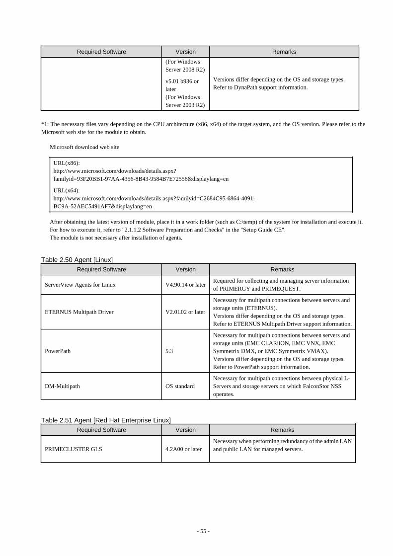
Required Software Version Remarks
(For WindowsServer 2008 R2)
v5.01 b936 orlater(For WindowsServer 2003 R2)
Versions differ depending on the OS and storage types.Refer to DynaPath support information.
*1: The necessary files vary depending on the CPU architecture (x86, x64) of the target system, and the OS version. Please refer to theMicrosoft web site for the module to obtain.
Microsoft download web site
URL(x86):http://www.microsoft.com/downloads/details.aspx?familyid=93F20BB1-97AA-4356-8B43-9584B7E72556&displaylang=en
URL(x64):http://www.microsoft.com/downloads/details.aspx?familyid=C2684C95-6864-4091-BC9A-52AEC5491AF7&displaylang=en
After obtaining the latest version of module, place it in a work folder (such as C:\temp) of the system for installation and execute it.For how to execute it, refer to "2.1.1.2 Software Preparation and Checks" in the "Setup Guide CE".The module is not necessary after installation of agents.
Table 2.50 Agent [Linux]
Required Software Version Remarks
ServerView Agents for Linux V4.90.14 or laterRequired for collecting and managing server informationof PRIMERGY and PRIMEQUEST.
ETERNUS Multipath Driver V2.0L02 or later
Necessary for multipath connections between servers andstorage units (ETERNUS).Versions differ depending on the OS and storage types.Refer to ETERNUS Multipath Driver support information.
PowerPath 5.3
Necessary for multipath connections between servers andstorage units (EMC CLARiiON, EMC VNX, EMCSymmetrix DMX, or EMC Symmetrix VMAX).Versions differ depending on the OS and storage types.Refer to PowerPath support information.
DM-Multipath OS standardNecessary for multipath connections between physical L-Servers and storage servers on which FalconStor NSSoperates.
Table 2.51 Agent [Red Hat Enterprise Linux]
Required Software Version Remarks
PRIMECLUSTER GLS 4.2A00 or laterNecessary when performing redundancy of the admin LANand public LAN for managed servers.
- 55 -
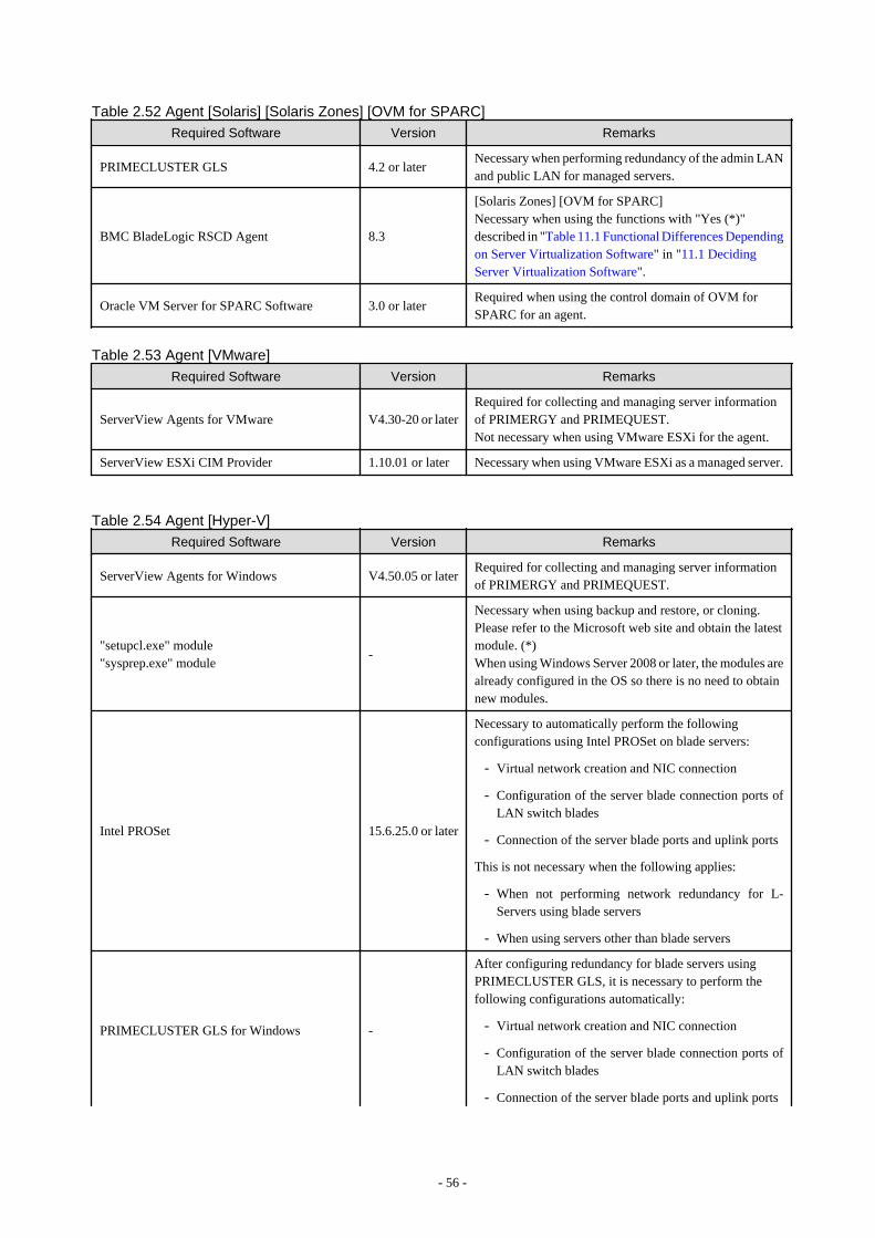
Table 2.52 Agent [Solaris] [Solaris Zones] [OVM for SPARC]Required Software Version Remarks
PRIMECLUSTER GLS 4.2 or laterNecessary when performing redundancy of the admin LANand public LAN for managed servers.
BMC BladeLogic RSCD Agent 8.3
[Solaris Zones] [OVM for SPARC]Necessary when using the functions with "Yes (*)"described in "Table 11.1 Functional Differences Dependingon Server Virtualization Software" in "11.1 DecidingServer Virtualization Software".
Oracle VM Server for SPARC Software 3.0 or laterRequired when using the control domain of OVM forSPARC for an agent.
Table 2.53 Agent [VMware]
Required Software Version Remarks
ServerView Agents for VMware V4.30-20 or laterRequired for collecting and managing server informationof PRIMERGY and PRIMEQUEST.Not necessary when using VMware ESXi for the agent.
ServerView ESXi CIM Provider 1.10.01 or later Necessary when using VMware ESXi as a managed server.
Table 2.54 Agent [Hyper-V]
Required Software Version Remarks
ServerView Agents for Windows V4.50.05 or laterRequired for collecting and managing server informationof PRIMERGY and PRIMEQUEST.
"setupcl.exe" module"sysprep.exe" module
-
Necessary when using backup and restore, or cloning.Please refer to the Microsoft web site and obtain the latestmodule. (*)When using Windows Server 2008 or later, the modules arealready configured in the OS so there is no need to obtainnew modules.
Intel PROSet 15.6.25.0 or later
Necessary to automatically perform the followingconfigurations using Intel PROSet on blade servers:
- Virtual network creation and NIC connection
- Configuration of the server blade connection ports ofLAN switch blades
- Connection of the server blade ports and uplink ports
This is not necessary when the following applies:
- When not performing network redundancy for L-Servers using blade servers
- When using servers other than blade servers
PRIMECLUSTER GLS for Windows -
After configuring redundancy for blade servers usingPRIMECLUSTER GLS, it is necessary to perform thefollowing configurations automatically:
- Virtual network creation and NIC connection
- Configuration of the server blade connection ports ofLAN switch blades
- Connection of the server blade ports and uplink ports
- 56 -

Required Software Version Remarks
This is not necessary when the following applies:
- When not performing network redundancy for L-Servers using blade servers
- When using servers other than blade servers
For details, refer to "2.2.7 Simplifying Networks".
*2: The necessary files vary depending on the CPU architecture (x86, x64) of the target system, and the OS version. Please refer to theMicrosoft web site for the module to obtain.
Microsoft download web site
URL(x86):http://www.microsoft.com/downloads/details.aspx?familyid=93F20BB1-97AA-4356-8B43-9584B7E72556&displaylang=en
URL(x64):http://www.microsoft.com/downloads/details.aspx?familyid=C2684C95-6864-4091-BC9A-52AEC5491AF7&displaylang=en
After obtaining the latest version of module, place it in a work folder (such as C:\temp) of the system for installation and execute it.For how to execute it, refer to "2.1.1.2 Software Preparation and Checks" in the "Setup Guide CE".The module is not necessary after installation of agents.
Table 2.55 Agent [Xen]
Required Software Version Remarks
ServerView Agents for Linux V4.81-14 or later Necessary when using PRIMEQUEST series servers.
PRIMECLUSTER GDS - Necessary when using RHEL5-Xen servers.
Table 2.56 Agent [KVM]
Required Software Version Remarks
ServerView Agents for Linux V5.1 or laterRequired for collecting and managing server informationof PRIMERGY and PRIMEQUEST.
Table 2.57 Agent [Citrix Xen]
Required Software Version Remarks
ServerView Agents for Citrix XenServer 4.92.66 or laterRequired for managing server information of PRIMERGYand PRIMEQUEST.
Table 2.58 Agent [OVM for x86 2.2] [OVM for x86 3.2]
Required Software Version Remarks
ServerView Agents for Linux 5.0 or laterRequired for collecting and managing server informationof PRIMERGY and PRIMEQUEST.
Required Software (HBA address rename Setup Service)
Table 2.59 HBA address rename setup service [Windows]
Required Software Version Remarks
Windows(R) Internet Explorer(R)89
Necessary for displaying the online help.
- 57 -
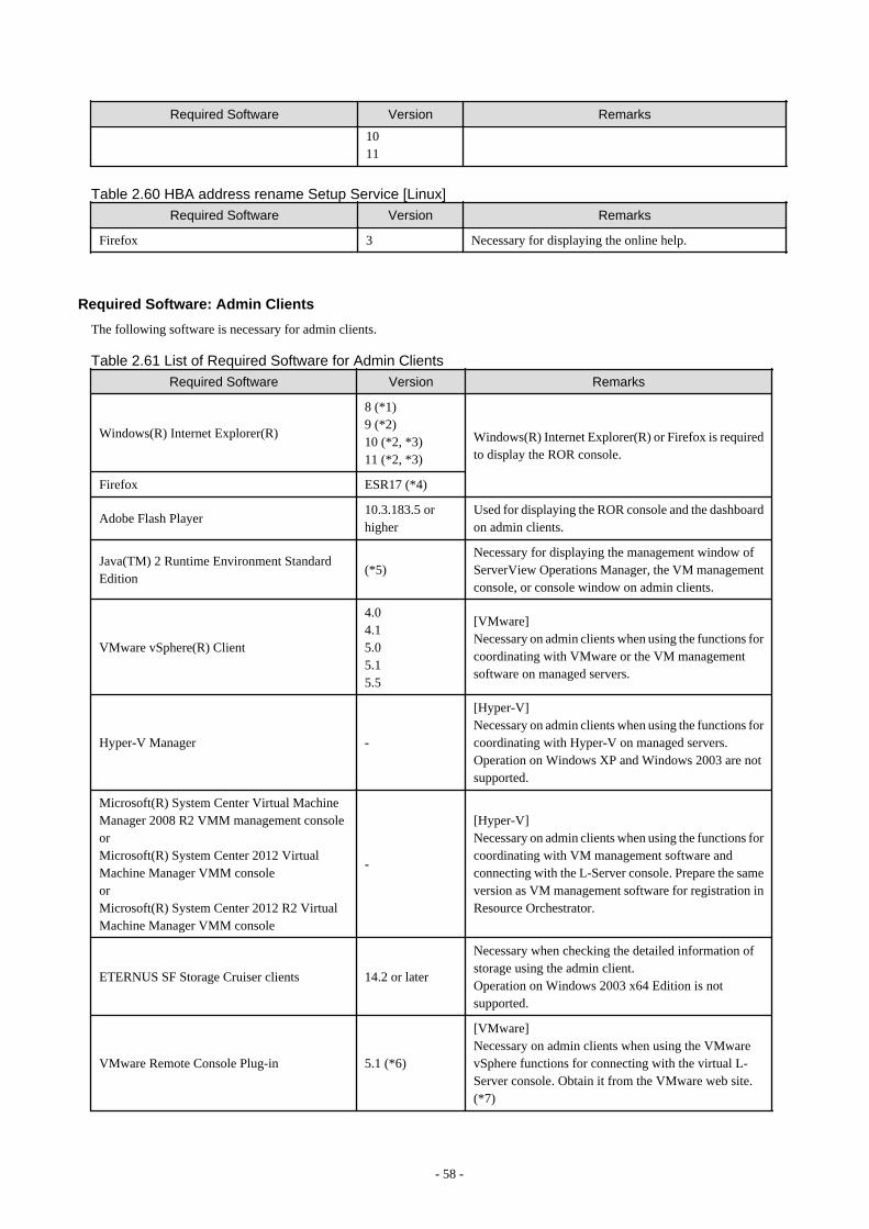
Required Software Version Remarks
1011
Table 2.60 HBA address rename Setup Service [Linux]
Required Software Version Remarks
Firefox 3 Necessary for displaying the online help.
Required Software: Admin Clients
The following software is necessary for admin clients.
Table 2.61 List of Required Software for Admin Clients
Required Software Version Remarks
Windows(R) Internet Explorer(R)
8 (*1)9 (*2)10 (*2, *3)11 (*2, *3)
Windows(R) Internet Explorer(R) or Firefox is requiredto display the ROR console.
Firefox ESR17 (*4)
Adobe Flash Player10.3.183.5 orhigher
Used for displaying the ROR console and the dashboardon admin clients.
Java(TM) 2 Runtime Environment StandardEdition
(*5)Necessary for displaying the management window ofServerView Operations Manager, the VM managementconsole, or console window on admin clients.
VMware vSphere(R) Client
4.04.15.05.15.5
[VMware]Necessary on admin clients when using the functions forcoordinating with VMware or the VM managementsoftware on managed servers.
Hyper-V Manager -
[Hyper-V]Necessary on admin clients when using the functions forcoordinating with Hyper-V on managed servers.Operation on Windows XP and Windows 2003 are notsupported.
Microsoft(R) System Center Virtual MachineManager 2008 R2 VMM management consoleorMicrosoft(R) System Center 2012 VirtualMachine Manager VMM consoleorMicrosoft(R) System Center 2012 R2 VirtualMachine Manager VMM console
-
[Hyper-V]Necessary on admin clients when using the functions forcoordinating with VM management software andconnecting with the L-Server console. Prepare the sameversion as VM management software for registration inResource Orchestrator.
ETERNUS SF Storage Cruiser clients 14.2 or later
Necessary when checking the detailed information ofstorage using the admin client.Operation on Windows 2003 x64 Edition is notsupported.
VMware Remote Console Plug-in 5.1 (*6)
[VMware]Necessary on admin clients when using the VMwarevSphere functions for connecting with the virtual L-Server console. Obtain it from the VMware web site.(*7)
- 58 -
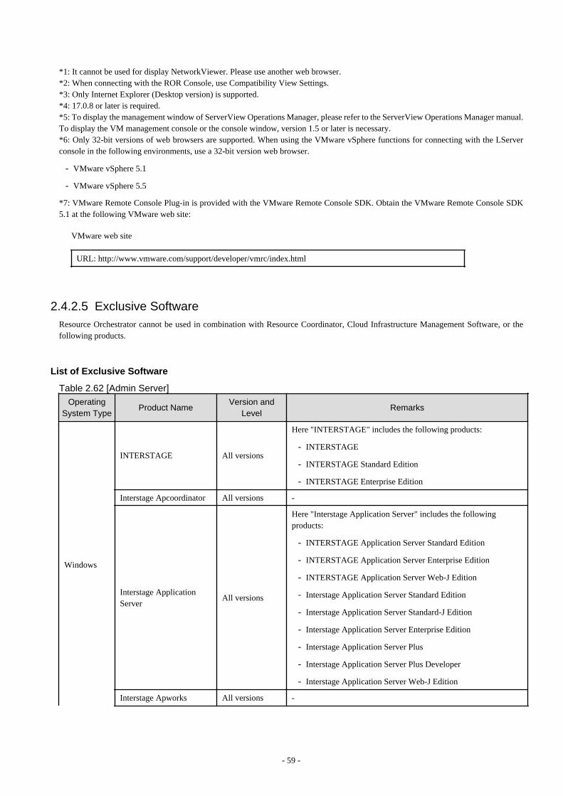
*1: It cannot be used for display NetworkViewer. Please use another web browser.*2: When connecting with the ROR Console, use Compatibility View Settings.*3: Only Internet Explorer (Desktop version) is supported.*4: 17.0.8 or later is required.*5: To display the management window of ServerView Operations Manager, please refer to the ServerView Operations Manager manual.To display the VM management console or the console window, version 1.5 or later is necessary.*6: Only 32-bit versions of web browsers are supported. When using the VMware vSphere functions for connecting with the LServerconsole in the following environments, use a 32-bit version web browser.
- VMware vSphere 5.1
- VMware vSphere 5.5
*7: VMware Remote Console Plug-in is provided with the VMware Remote Console SDK. Obtain the VMware Remote Console SDK5.1 at the following VMware web site:
VMware web site
URL: http://www.vmware.com/support/developer/vmrc/index.html
2.4.2.5 Exclusive SoftwareResource Orchestrator cannot be used in combination with Resource Coordinator, Cloud Infrastructure Management Software, or thefollowing products.
List of Exclusive Software
Table 2.62 [Admin Server]
OperatingSystem Type
Product NameVersion and
LevelRemarks
Windows
INTERSTAGE All versions
Here "INTERSTAGE" includes the following products:
- INTERSTAGE
- INTERSTAGE Standard Edition
- INTERSTAGE Enterprise Edition
Interstage Apcoordinator All versions -
Interstage ApplicationServer
All versions
Here "Interstage Application Server" includes the followingproducts:
- INTERSTAGE Application Server Standard Edition
- INTERSTAGE Application Server Enterprise Edition
- INTERSTAGE Application Server Web-J Edition
- Interstage Application Server Standard Edition
- Interstage Application Server Standard-J Edition
- Interstage Application Server Enterprise Edition
- Interstage Application Server Plus
- Interstage Application Server Plus Developer
- Interstage Application Server Web-J Edition
Interstage Apworks All versions -
- 59 -

OperatingSystem Type
Product NameVersion and
LevelRemarks
Interstage ApplicationFramework Suite
All versions -
Interstage BusinessApplication Server
All versions
Here "Interstage Business Application Server" includes the followingproducts:
- Interstage Business Application ServerStandard Edition
- Interstage Business Application ServerEnterprise Edition
Interstage BusinessProcess Manager
All versions -
Interstage BusinessProcess Manager Analytics
All versions -
Interstage BPM Flow All versions -
Interstage ServiceIntegrator
All versions -
Interstage SecurityDirectory
All versions -
Interstage Shunsaku DataManager
All versions -
Interstage Studio All versions -
Interstage Traffic Director All versions -
INTERSTAGEWEBCOORDINATOR
All versions -
Interstage Web Server All versions -
ObjectDirector All versions -
Systemwalker CentricManager(Operation ManagementServer/SectionManagement Server/JobServer)
All versions(*6)
Here "Systemwalker Centric Manager" includes the followingproducts:
- SystemWalker/CentricMGR
- SystemWalker/CentricMGR-M
- SystemWalker/CentricMGR GEE
- SystemWalker/CentricMGR EE
- SystemWalker/CentricMGR SE
- Systemwalker Centric Manager Global Enterprise Edition
- Systemwalker Centric Manager Enterprise Edition
- Systemwalker Centric Manager Standard Edition
Systemwalker IT ChangeManager
All versions
Here "Systemwalker IT Change Manager" includes the followingproducts:
- Systemwalker IT Change Manager Enterprise Edition
- Systemwalker IT Change Manager Standard Edition
Systemwalker IT ProcessMaster
All versions -
- 60 -
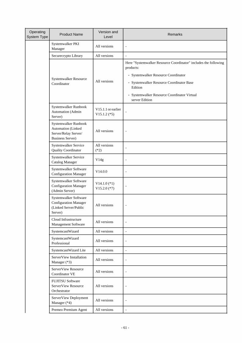
OperatingSystem Type
Product NameVersion and
LevelRemarks
Systemwalker PKIManager
All versions -
Securecrypto Library All versions -
Systemwalker ResourceCoordinator
All versions
Here "Systemwalker Resource Coordinator" includes the followingproducts:
- Systemwalker Resource Coordinator
- Systemwalker Resource Coordinator BaseEdition
- Systemwalker Resource Coordinator Virtualserver Edition
Systemwalker RunbookAutomation (AdminServer)
V15.1.1 or earlierV15.1.2 (*5)
-
Systemwalker RunbookAutomation (LinkedServer/Relay Server/Business Server)
All versions -
Systemwalker ServiceQuality Coordinator
All versions(*2)
-
Systemwalker ServiceCatalog Manager
V14g -
Systemwalker SoftwareConfiguration Manager
V14.0.0 -
Systemwalker SoftwareConfiguration Manager(Admin Server)
V14.1.0 (*1)V15.2.0 (*7)
-
Systemwalker SoftwareConfiguration Manager(Linked Server/PublicServer)
All versions -
Cloud InfrastructureManagement Software
All versions -
SystemcastWizard All versions -
SystemcastWizardProfessional
All versions -
SystemcastWizard Lite All versions -
ServerView InstallationManager (*3)
All versions -
ServerView ResourceCoordinator VE
All versions -
FUJITSU SoftwareServerView ResourceOrchestrator
All versions -
ServerView DeploymentManager (*4)
All versions -
Premeo Premium Agent All versions -
- 61 -
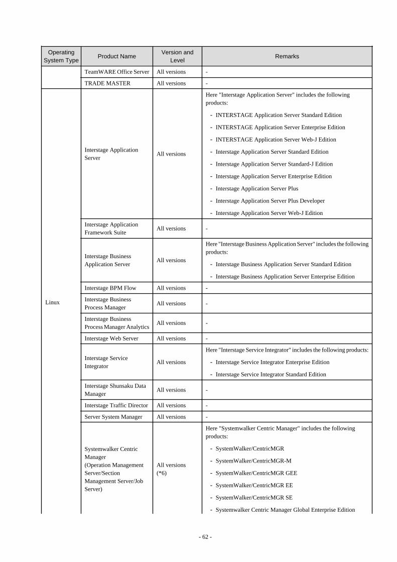
OperatingSystem Type
Product NameVersion and
LevelRemarks
TeamWARE Office Server All versions -
TRADE MASTER All versions -
Linux
Interstage ApplicationServer
All versions
Here "Interstage Application Server" includes the followingproducts:
- INTERSTAGE Application Server Standard Edition
- INTERSTAGE Application Server Enterprise Edition
- INTERSTAGE Application Server Web-J Edition
- Interstage Application Server Standard Edition
- Interstage Application Server Standard-J Edition
- Interstage Application Server Enterprise Edition
- Interstage Application Server Plus
- Interstage Application Server Plus Developer
- Interstage Application Server Web-J Edition
Interstage ApplicationFramework Suite
All versions -
Interstage BusinessApplication Server
All versions
Here "Interstage Business Application Server" includes the followingproducts:
- Interstage Business Application Server Standard Edition
- Interstage Business Application Server Enterprise Edition
Interstage BPM Flow All versions -
Interstage BusinessProcess Manager
All versions -
Interstage BusinessProcess Manager Analytics
All versions -
Interstage Web Server All versions -
Interstage ServiceIntegrator
All versions
Here "Interstage Service Integrator" includes the following products:
- Interstage Service Integrator Enterprise Edition
- Interstage Service Integrator Standard Edition
Interstage Shunsaku DataManager
All versions -
Interstage Traffic Director All versions -
Server System Manager All versions -
Systemwalker CentricManager(Operation ManagementServer/SectionManagement Server/JobServer)
All versions(*6)
Here "Systemwalker Centric Manager" includes the followingproducts:
- SystemWalker/CentricMGR
- SystemWalker/CentricMGR-M
- SystemWalker/CentricMGR GEE
- SystemWalker/CentricMGR EE
- SystemWalker/CentricMGR SE
- Systemwalker Centric Manager Global Enterprise Edition
- 62 -
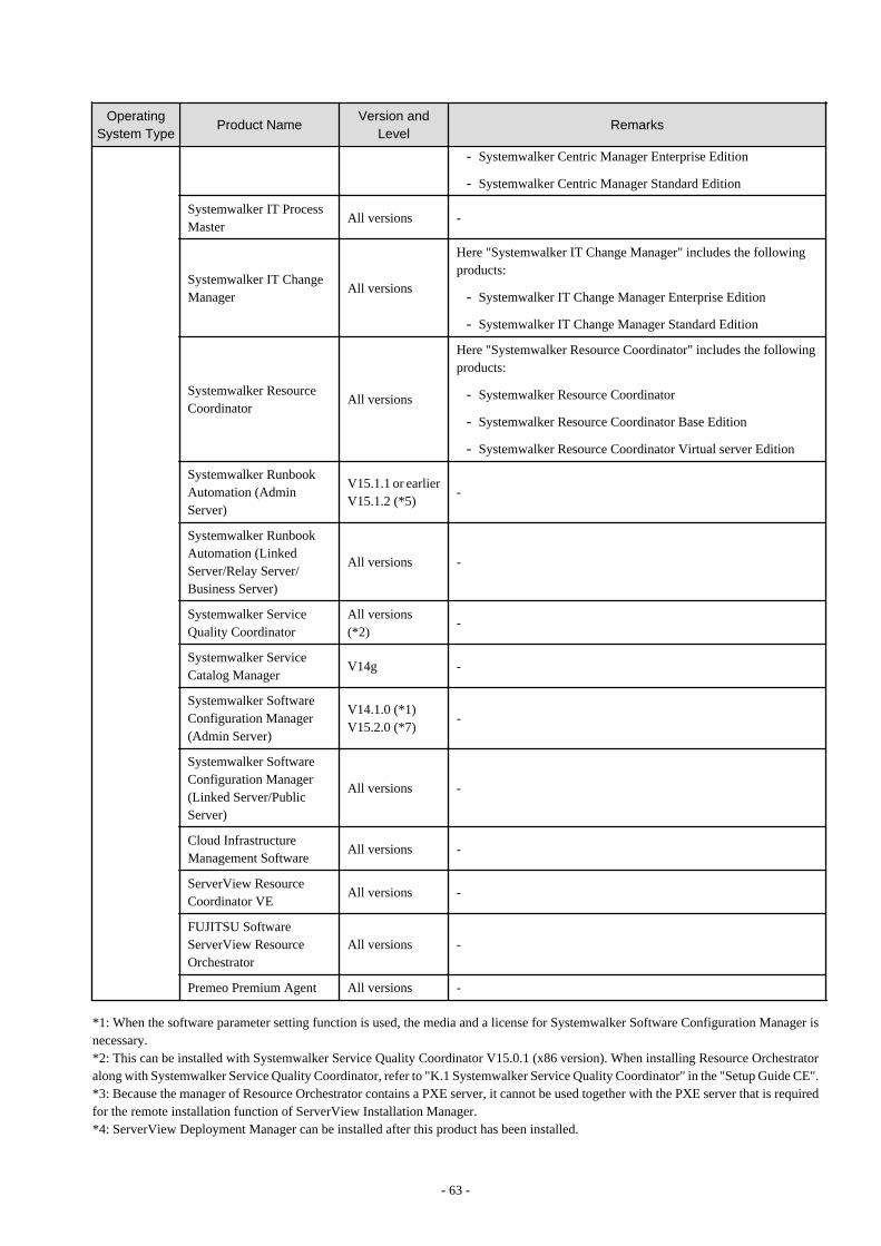
OperatingSystem Type
Product NameVersion and
LevelRemarks
- Systemwalker Centric Manager Enterprise Edition
- Systemwalker Centric Manager Standard Edition
Systemwalker IT ProcessMaster
All versions -
Systemwalker IT ChangeManager
All versions
Here "Systemwalker IT Change Manager" includes the followingproducts:
- Systemwalker IT Change Manager Enterprise Edition
- Systemwalker IT Change Manager Standard Edition
Systemwalker ResourceCoordinator
All versions
Here "Systemwalker Resource Coordinator" includes the followingproducts:
- Systemwalker Resource Coordinator
- Systemwalker Resource Coordinator Base Edition
- Systemwalker Resource Coordinator Virtual server Edition
Systemwalker RunbookAutomation (AdminServer)
V15.1.1 or earlierV15.1.2 (*5)
-
Systemwalker RunbookAutomation (LinkedServer/Relay Server/Business Server)
All versions -
Systemwalker ServiceQuality Coordinator
All versions(*2)
-
Systemwalker ServiceCatalog Manager
V14g -
Systemwalker SoftwareConfiguration Manager(Admin Server)
V14.1.0 (*1)V15.2.0 (*7)
-
Systemwalker SoftwareConfiguration Manager(Linked Server/PublicServer)
All versions -
Cloud InfrastructureManagement Software
All versions -
ServerView ResourceCoordinator VE
All versions -
FUJITSU SoftwareServerView ResourceOrchestrator
All versions -
Premeo Premium Agent All versions -
*1: When the software parameter setting function is used, the media and a license for Systemwalker Software Configuration Manager isnecessary.*2: This can be installed with Systemwalker Service Quality Coordinator V15.0.1 (x86 version). When installing Resource Orchestratoralong with Systemwalker Service Quality Coordinator, refer to "K.1 Systemwalker Service Quality Coordinator" in the "Setup Guide CE".*3: Because the manager of Resource Orchestrator contains a PXE server, it cannot be used together with the PXE server that is requiredfor the remote installation function of ServerView Installation Manager.*4: ServerView Deployment Manager can be installed after this product has been installed.
- 63 -
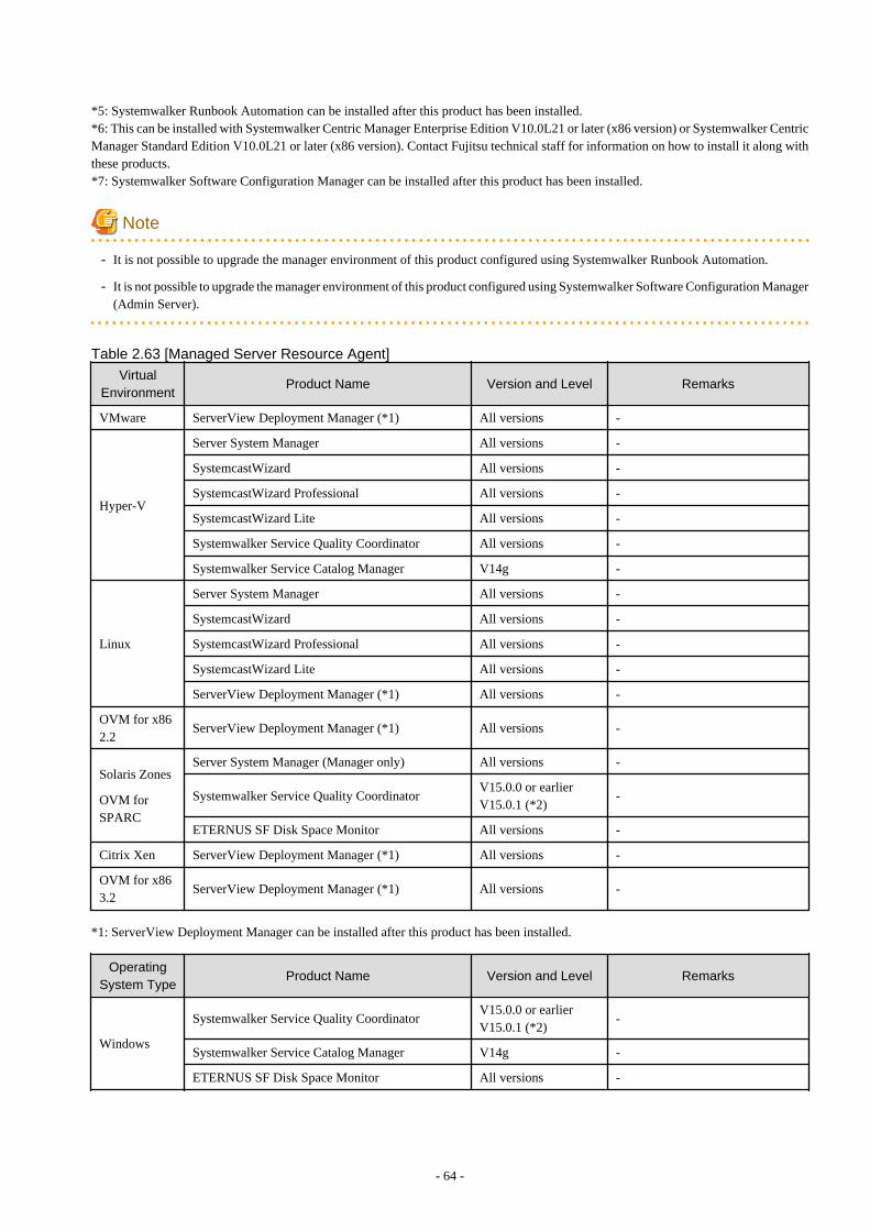
*5: Systemwalker Runbook Automation can be installed after this product has been installed.*6: This can be installed with Systemwalker Centric Manager Enterprise Edition V10.0L21 or later (x86 version) or Systemwalker CentricManager Standard Edition V10.0L21 or later (x86 version). Contact Fujitsu technical staff for information on how to install it along withthese products.*7: Systemwalker Software Configuration Manager can be installed after this product has been installed.
Note
- It is not possible to upgrade the manager environment of this product configured using Systemwalker Runbook Automation.
- It is not possible to upgrade the manager environment of this product configured using Systemwalker Software Configuration Manager(Admin Server).
Table 2.63 [Managed Server Resource Agent]
VirtualEnvironment
Product Name Version and Level Remarks
VMware ServerView Deployment Manager (*1) All versions -
Hyper-V
Server System Manager All versions -
SystemcastWizard All versions -
SystemcastWizard Professional All versions -
SystemcastWizard Lite All versions -
Systemwalker Service Quality Coordinator All versions -
Systemwalker Service Catalog Manager V14g -
Linux
Server System Manager All versions -
SystemcastWizard All versions -
SystemcastWizard Professional All versions -
SystemcastWizard Lite All versions -
ServerView Deployment Manager (*1) All versions -
OVM for x862.2
ServerView Deployment Manager (*1) All versions -
Solaris Zones
OVM forSPARC
Server System Manager (Manager only) All versions -
Systemwalker Service Quality CoordinatorV15.0.0 or earlierV15.0.1 (*2)
-
ETERNUS SF Disk Space Monitor All versions -
Citrix Xen ServerView Deployment Manager (*1) All versions -
OVM for x863.2
ServerView Deployment Manager (*1) All versions -
*1: ServerView Deployment Manager can be installed after this product has been installed.
Operating
System TypeProduct Name Version and Level Remarks
Windows
Systemwalker Service Quality CoordinatorV15.0.0 or earlierV15.0.1 (*2)
-
Systemwalker Service Catalog Manager V14g -
ETERNUS SF Disk Space Monitor All versions -
- 64 -
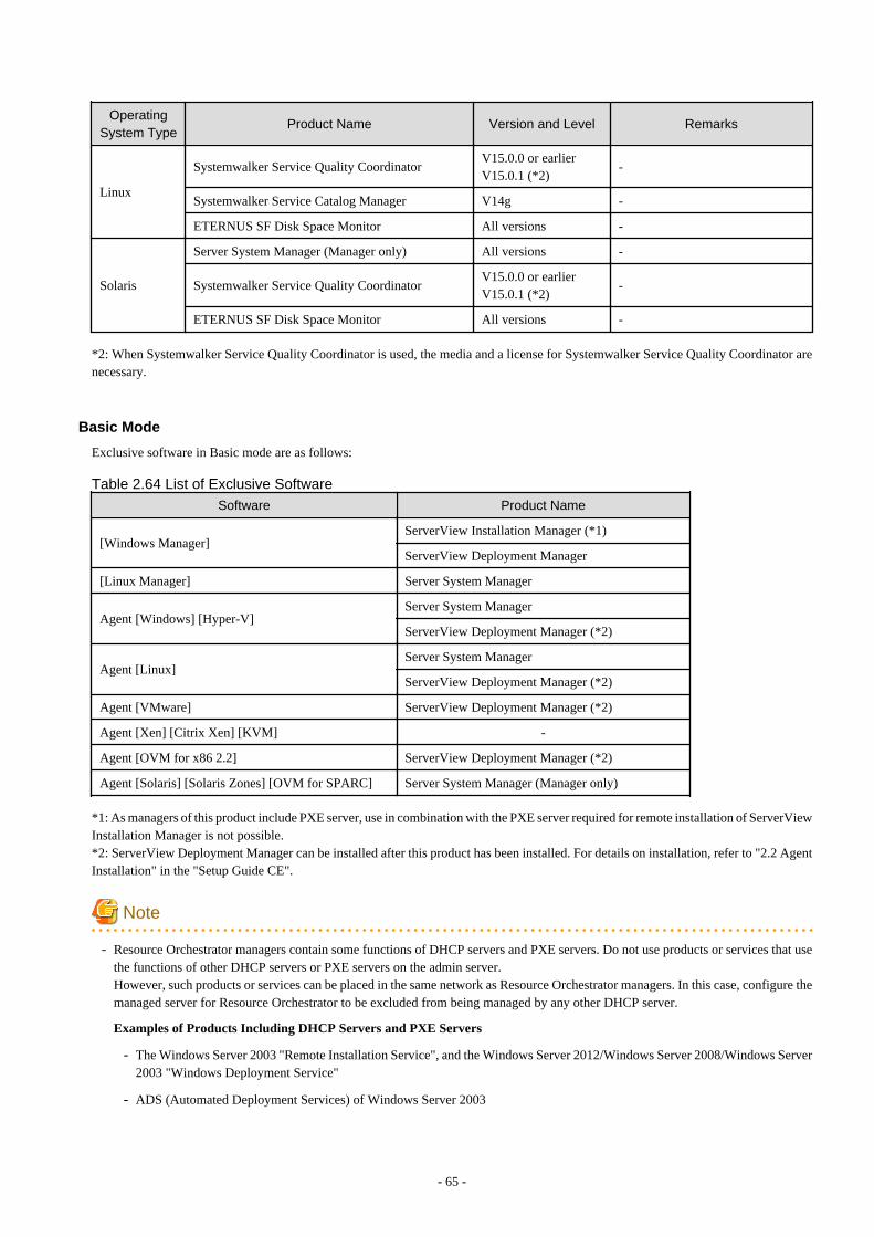
OperatingSystem Type
Product Name Version and Level Remarks
Linux
Systemwalker Service Quality CoordinatorV15.0.0 or earlierV15.0.1 (*2)
-
Systemwalker Service Catalog Manager V14g -
ETERNUS SF Disk Space Monitor All versions -
Solaris
Server System Manager (Manager only) All versions -
Systemwalker Service Quality CoordinatorV15.0.0 or earlierV15.0.1 (*2)
-
ETERNUS SF Disk Space Monitor All versions -
*2: When Systemwalker Service Quality Coordinator is used, the media and a license for Systemwalker Service Quality Coordinator arenecessary.
Basic Mode
Exclusive software in Basic mode are as follows:
Table 2.64 List of Exclusive Software
Software Product Name
[Windows Manager]ServerView Installation Manager (*1)
ServerView Deployment Manager
[Linux Manager] Server System Manager
Agent [Windows] [Hyper-V]Server System Manager
ServerView Deployment Manager (*2)
Agent [Linux]Server System Manager
ServerView Deployment Manager (*2)
Agent [VMware] ServerView Deployment Manager (*2)
Agent [Xen] [Citrix Xen] [KVM] -
Agent [OVM for x86 2.2] ServerView Deployment Manager (*2)
Agent [Solaris] [Solaris Zones] [OVM for SPARC] Server System Manager (Manager only)
*1: As managers of this product include PXE server, use in combination with the PXE server required for remote installation of ServerViewInstallation Manager is not possible.*2: ServerView Deployment Manager can be installed after this product has been installed. For details on installation, refer to "2.2 AgentInstallation" in the "Setup Guide CE".
Note
- Resource Orchestrator managers contain some functions of DHCP servers and PXE servers. Do not use products or services that usethe functions of other DHCP servers or PXE servers on the admin server.However, such products or services can be placed in the same network as Resource Orchestrator managers. In this case, configure themanaged server for Resource Orchestrator to be excluded from being managed by any other DHCP server.
Examples of Products Including DHCP Servers and PXE Servers
- The Windows Server 2003 "Remote Installation Service", and the Windows Server 2012/Windows Server 2008/Windows Server2003 "Windows Deployment Service"
- ADS (Automated Deployment Services) of Windows Server 2003
- 65 -
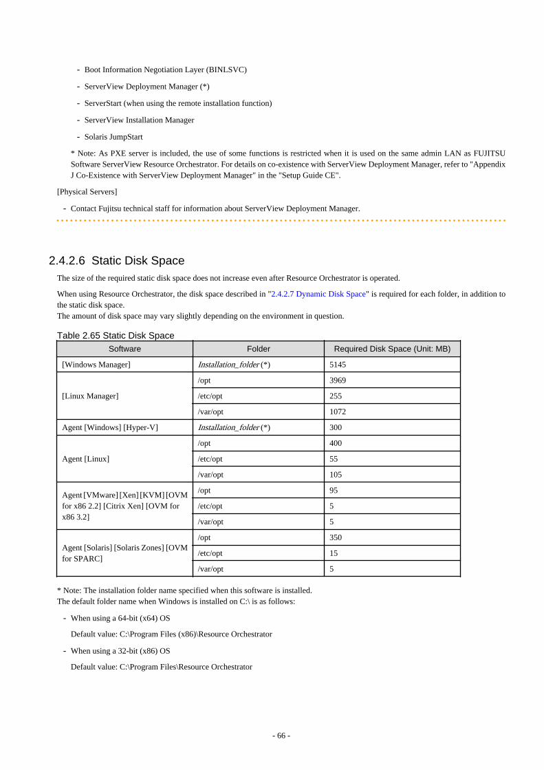
- Boot Information Negotiation Layer (BINLSVC)
- ServerView Deployment Manager (*)
- ServerStart (when using the remote installation function)
- ServerView Installation Manager
- Solaris JumpStart
* Note: As PXE server is included, the use of some functions is restricted when it is used on the same admin LAN as FUJITSUSoftware ServerView Resource Orchestrator. For details on co-existence with ServerView Deployment Manager, refer to "AppendixJ Co-Existence with ServerView Deployment Manager" in the "Setup Guide CE".
[Physical Servers]
- Contact Fujitsu technical staff for information about ServerView Deployment Manager.
2.4.2.6 Static Disk SpaceThe size of the required static disk space does not increase even after Resource Orchestrator is operated.
When using Resource Orchestrator, the disk space described in "2.4.2.7 Dynamic Disk Space" is required for each folder, in addition tothe static disk space.The amount of disk space may vary slightly depending on the environment in question.
Table 2.65 Static Disk Space
Software Folder Required Disk Space (Unit: MB)
[Windows Manager] Installation_folder (*) 5145
[Linux Manager]
/opt 3969
/etc/opt 255
/var/opt 1072
Agent [Windows] [Hyper-V] Installation_folder (*) 300
Agent [Linux]
/opt 400
/etc/opt 55
/var/opt 105
Agent [VMware] [Xen] [KVM] [OVMfor x86 2.2] [Citrix Xen] [OVM forx86 3.2]
/opt 95
/etc/opt 5
/var/opt 5
Agent [Solaris] [Solaris Zones] [OVMfor SPARC]
/opt 350
/etc/opt 15
/var/opt 5
* Note: The installation folder name specified when this software is installed.The default folder name when Windows is installed on C:\ is as follows:
- When using a 64-bit (x64) OS
Default value: C:\Program Files (x86)\Resource Orchestrator
- When using a 32-bit (x86) OS
Default value: C:\Program Files\Resource Orchestrator
- 66 -
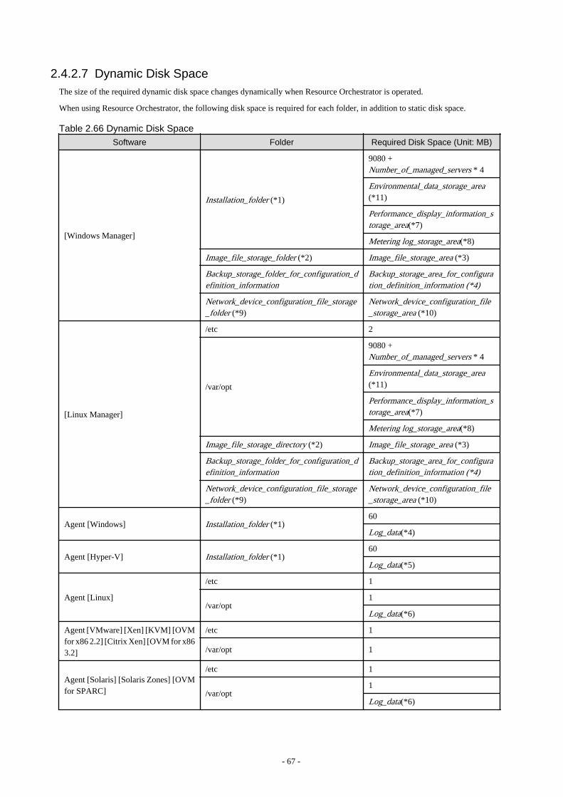
2.4.2.7 Dynamic Disk SpaceThe size of the required dynamic disk space changes dynamically when Resource Orchestrator is operated.
When using Resource Orchestrator, the following disk space is required for each folder, in addition to static disk space.
Table 2.66 Dynamic Disk Space
Software Folder Required Disk Space (Unit: MB)
[Windows Manager]
Installation_folder (*1)
9080 +Number_of_managed_servers * 4
Environmental_data_storage_area(*11)
Performance_display_information_storage_area(*7)
Metering log_storage_area(*8)
Image_file_storage_folder (*2) Image_file_storage_area (*3)
Backup_storage_folder_for_configuration_definition_information
Backup_storage_area_for_configuration_definition_information (*4)
Network_device_configuration_file_storage_folder (*9)
Network_device_configuration_file_storage_area (*10)
[Linux Manager]
/etc 2
/var/opt
9080 +Number_of_managed_servers * 4
Environmental_data_storage_area(*11)
Performance_display_information_storage_area(*7)
Metering log_storage_area(*8)
Image_file_storage_directory (*2) Image_file_storage_area (*3)
Backup_storage_folder_for_configuration_definition_information
Backup_storage_area_for_configuration_definition_information (*4)
Network_device_configuration_file_storage_folder (*9)
Network_device_configuration_file_storage_area (*10)
Agent [Windows] Installation_folder (*1)60
Log_data(*4)
Agent [Hyper-V] Installation_folder (*1)60
Log_data(*5)
Agent [Linux]
/etc 1
/var/opt1
Log_data(*6)
Agent [VMware] [Xen] [KVM] [OVMfor x86 2.2] [Citrix Xen] [OVM for x863.2]
/etc 1
/var/opt 1
Agent [Solaris] [Solaris Zones] [OVMfor SPARC]
/etc 1
/var/opt1
Log_data(*6)
- 67 -
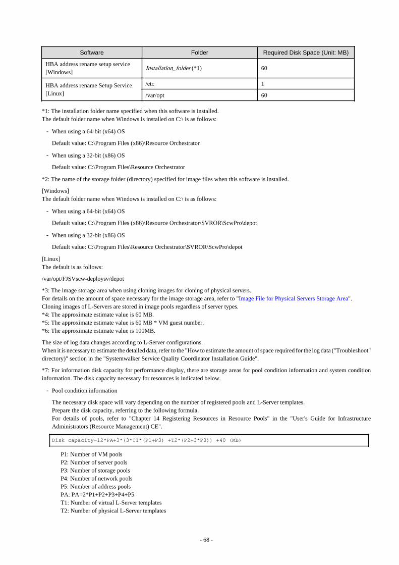
Software Folder Required Disk Space (Unit: MB)
HBA address rename setup service[Windows]
Installation_folder (*1) 60
HBA address rename Setup Service[Linux]
/etc 1
/var/opt 60
*1: The installation folder name specified when this software is installed.The default folder name when Windows is installed on C:\ is as follows:
- When using a 64-bit (x64) OS
Default value: C:\Program Files (x86)\Resource Orchestrator
- When using a 32-bit (x86) OS
Default value: C:\Program Files\Resource Orchestrator
*2: The name of the storage folder (directory) specified for image files when this software is installed.
[Windows]The default folder name when Windows is installed on C:\ is as follows:
- When using a 64-bit (x64) OS
Default value: C:\Program Files (x86)\Resource Orchestrator\SVROR\ScwPro\depot
- When using a 32-bit (x86) OS
Default value: C:\Program Files\Resource Orchestrator\SVROR\ScwPro\depot
[Linux]The default is as follows:
/var/opt/FJSVscw-deploysv/depot
*3: The image storage area when using cloning images for cloning of physical servers.For details on the amount of space necessary for the image storage area, refer to "Image File for Physical Servers Storage Area".Cloning images of L-Servers are stored in image pools regardless of server types.*4: The approximate estimate value is 60 MB.*5: The approximate estimate value is 60 MB * VM guest number.*6: The approximate estimate value is 100MB.
The size of log data changes according to L-Server configurations.When it is necessary to estimate the detailed data, refer to the "How to estimate the amount of space required for the log data ("Troubleshoot"directory)" section in the "Systemwalker Service Quality Coordinator Installation Guide".
*7: For information disk capacity for performance display, there are storage areas for pool condition information and system conditioninformation. The disk capacity necessary for resources is indicated below.
- Pool condition information
The necessary disk space will vary depending on the number of registered pools and L-Server templates.Prepare the disk capacity, referring to the following formula.For details of pools, refer to "Chapter 14 Registering Resources in Resource Pools" in the "User's Guide for InfrastructureAdministrators (Resource Management) CE".
Disk capacity=12*PA+3*(3*T1*(P1+P3) +T2*(P2+3*P3)) +40 (MB)
P1: Number of VM poolsP2: Number of server poolsP3: Number of storage poolsP4: Number of network poolsP5: Number of address poolsPA: PA=2*P1+P2+P3+P4+P5T1: Number of virtual L-Server templatesT2: Number of physical L-Server templates
- 68 -
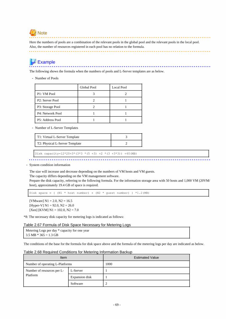
Note
Here the numbers of pools are a combination of the relevant pools in the global pool and the relevant pools in the local pool.Also, the number of resources registered in each pool has no relation to the formula.
Example
The following shows the formula when the numbers of pools and L-Server templates are as below.
- Number of Pools
Global Pool Local Pool
P1: VM Pool 3 2
P2: Server Pool 2 1
P3: Storage Pool 2 1
P4: Network Pool 1 1
P5: Address Pool 1 1
- Number of L-Server Templates
T1: Virtual L-Server Template 3
T2: Physical L-Server Template 2
Disk capacity=12*20+3*(3*3 *(5 +3) +2 *(3 +3*3)) +40(MB)
- System condition information
The size will increase and decrease depending on the numbers of VM hosts and VM guests.The capacity differs depending on the VM management software.Prepare the disk capacity, referring to the following formula. For the information storage area with 50 hosts and 1,000 VM (20VM/host), approximately 19.4 GB of space is required.
Disk space = ( (N1 * host number) + (N2 * guest number) ) *1.2(MB)
[VMware] N1 = 2.0, N2 = 16.5[Hyper-V] N1 = 92.0, N2 = 26.0[Xen] [KVM] N1 = 102.0, N2 = 7.0
*8: The necessary disk capacity for metering logs is indicated as follows:
Table 2.67 Formula of Disk Space Necessary for Metering Logs
Metering Logs per day * capacity for one year3.5 MB * 365 = 1.3 GB
The conditions of the base for the formula for disk space above and the formula of the metering logs per day are indicated as below.
Table 2.68 Required Conditions for Metering Information Backup
Item Estimated Value
Number of operating L-Platforms 1000
Number of resources per L-Platform
L-Server 1
Expansion disk 1
Software 2
- 69 -
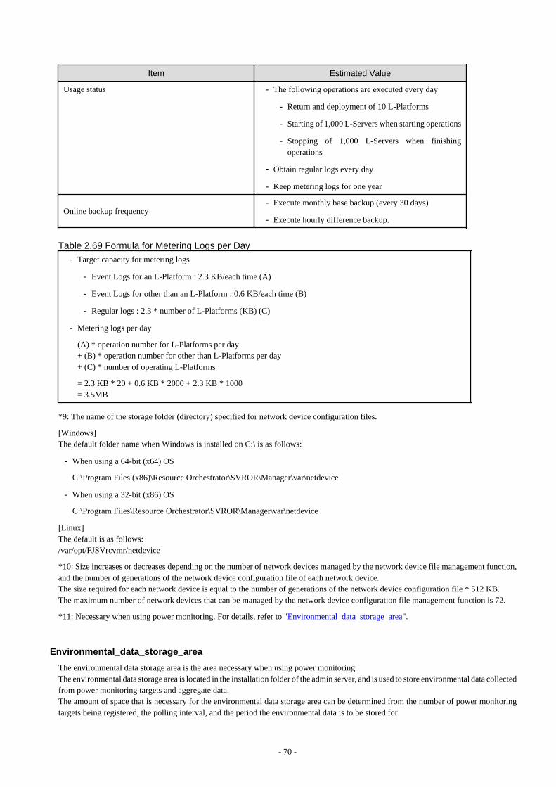
Item Estimated Value
Usage status - The following operations are executed every day
- Return and deployment of 10 L-Platforms
- Starting of 1,000 L-Servers when starting operations
- Stopping of 1,000 L-Servers when finishingoperations
- Obtain regular logs every day
- Keep metering logs for one year
Online backup frequency- Execute monthly base backup (every 30 days)
- Execute hourly difference backup.
Table 2.69 Formula for Metering Logs per Day
- Target capacity for metering logs
- Event Logs for an L-Platform : 2.3 KB/each time (A)
- Event Logs for other than an L-Platform : 0.6 KB/each time (B)
- Regular logs : 2.3 * number of L-Platforms (KB) (C)
- Metering logs per day
(A) * operation number for L-Platforms per day+ (B) * operation number for other than L-Platforms per day+ (C) * number of operating L-Platforms
= 2.3 KB * 20 + 0.6 KB * 2000 + 2.3 KB * 1000= 3.5MB
*9: The name of the storage folder (directory) specified for network device configuration files.
[Windows]The default folder name when Windows is installed on C:\ is as follows:
- When using a 64-bit (x64) OS
C:\Program Files (x86)\Resource Orchestrator\SVROR\Manager\var\netdevice
- When using a 32-bit (x86) OS
C:\Program Files\Resource Orchestrator\SVROR\Manager\var\netdevice
[Linux]The default is as follows:/var/opt/FJSVrcvmr/netdevice
*10: Size increases or decreases depending on the number of network devices managed by the network device file management function,and the number of generations of the network device configuration file of each network device.The size required for each network device is equal to the number of generations of the network device configuration file * 512 KB.The maximum number of network devices that can be managed by the network device configuration file management function is 72.
*11: Necessary when using power monitoring. For details, refer to "Environmental_data_storage_area".
Environmental_data_storage_area
The environmental data storage area is the area necessary when using power monitoring.The environmental data storage area is located in the installation folder of the admin server, and is used to store environmental data collectedfrom power monitoring targets and aggregate data.The amount of space that is necessary for the environmental data storage area can be determined from the number of power monitoringtargets being registered, the polling interval, and the period the environmental data is to be stored for.
- 70 -

For details on each setting, refer to "13.1.1 Settings for the Power Monitoring Environment".Estimate the necessary space using the following formula.
Necessary disk space (MB) = (detail_storage_period_(months) * 6 / polling_interval_(minutes) + 10) * 3 *number_of_power_monitoring_targets
Image File for Physical Servers Storage Area
The image file storage area for physical servers is necessary when performing backup and cloning.The image file storage area is secured on an admin server as an area to store the image files (system images and cloning images) collectedthrough the backup and cloning of managed servers.
Note
Create the image file storage area on the local disk of the admin server, or SAN storage. It is not possible to specify folders on networkdrives, shared folders (NFS, SMB, etc.) on other machines on a network, or UNC format folders.
The space necessary for the image file storage area is the total amount of disk space necessary for the "system image storage area", the"cloning image storage area", and the "temporary work area".Estimate the necessary space based on the disk space required for each storage area using the following formula.
Estimate the necessary space for the image file storage area using the following procedure.
1. Calculate the size of image files.
Calculate the image file sizes as base data for estimating the required disk space for A, B, and C indicated above.The calculation method is given below.
File size of image files = disk_space_per_managed_server * compression_ratio
Disk_space_per_managed_server
When system construction using the same software configuration has been performed before, use the consumed disk space ofthat system (the sum of the disk space for each partition when dividing one disk into multiple partitions).Check the consumed disk space using the relevant OS function.When system construction using the same software configuration has not been performed before, calculate the disk space fromthe required disk space indicated in the installation guide for each piece of software.For the OS, refer to "Examples of Calculation".
Compression_ratio
The compression ratio involved when storing the consumed disk space of managed servers as an image file on the admin server.Compression ratio is dependent on file content, and usually a compression ratio of around 50% can be expected. When thereare many files that have already been compressed (installation media of software, image data, or other media), the overallcompression ratio is lower.For the OS, refer to "Examples of Calculation".
An example of the calculation of disk space and the compression ratio directly after OS installation is given below.
Example
Examples of Calculation
- 71 -
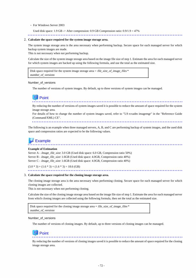
- For Windows Server 2003
Used disk space: 1.9 GB -> After compression: 0.9 GB Compression ratio: 0.9/1.9 = 47%
2. Calculate the space required for the system image storage area.
The system image storage area is the area necessary when performing backup. Secure space for each managed server for whichbackup system images are made.This is not necessary when not performing backup.
Calculate the size of the system image storage area based on the image file size of step 1. Estimate the area for each managed serverfor which system images are backed up using the following formula, and use the total as the estimated size.
Disk space required for the system image storage area = file_size_of_image_files *number_of_versions
Number_of_versions
The number of versions of system images. By default, up to three versions of system images can be managed.
Point
By reducing the number of versions of system images saved it is possible to reduce the amount of space required for the systemimage storage area.For details of how to change the number of system images saved, refer to "5.9 rcxadm imagemgr" in the "Reference Guide(Command/XML) CE".
The following is an example when three managed servers, A, B, and C are performing backup of system images, and the used diskspace and compression ratios are expected to be the following values.
Example
Example of EstimationServer A - Image_file_size: 3.0 GB (Used disk space: 6.0 GB, Compression ratio 50%)Server B - Image_file_size: 1.6GB (Used disk space: 4.0GB, Compression ratio 40%)Server C - Image_file_size: 1.6GB (Used disk space: 4.0GB, Compression ratio 40%)
(3.0 * 3) + (1.6 * 3) + (1.6 * 3) = 18.6 (GB)
3. Calculate the space required for the cloning image storage area.
The cloning image storage area is the area necessary when performing cloning. Secure space for each managed server for whichcloning images are collected.This is not necessary when not performing cloning.
Calculate the size of the cloning image storage area based on the image file size of step 1. Estimate the area for each managed serverfrom which cloning images are collected using the following formula, then set the total as the estimated size.
Disk space required for the cloning image storage area = file_size_of_image_files *number_of_versions
Number_of_versions
The number of versions of cloning images. By default, up to three versions of cloning images can be managed.
Point
By reducing the number of versions of cloning images saved it is possible to reduce the amount of space required for the cloningimage storage area.
- 72 -
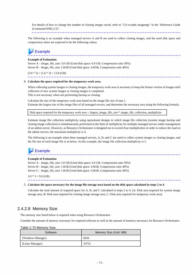
For details of how to change the number of cloning images saved, refer to "5.9 rcxadm imagemgr" in the "Reference Guide(Command/XML) CE".
The following is an example when managed servers A and B are used to collect cloning images, and the used disk space andcompression ratios are expected to be the following values.
Example
Example of EstimationServer A - Image_file_size: 3.0 GB (Used disk space: 6.0 GB, Compression ratio 50%)Server B - Image_file_size: 1.6GB (Used disk space: 4.0GB, Compression ratio 40%)
(3.0 * 3) + (1.6 * 3) = 13.8 (GB)
4. Calculate the space required for the temporary work area.
When collecting system images or cloning images, the temporary work area is necessary to keep the former version of images untilcollection of new system images or cloning images is completed.This is not necessary when not performing backup or cloning.
Calculate the size of the temporary work area based on the image file size of step 1.Estimate the largest size of the image files of all managed servers, and determine the necessary area using the following formula.
Disk space required for the temporary work area = largest_image_file_size * image_file_collection_multiplicity
Estimate image file collection multiplicity using operational designs in which image file collection (system image backup andcloning image collection) is simultaneously performed at the limit of multiplicity for multiple managed servers under managementof an admin server. However, as Resource Orchestrator is designed not to exceed four multiplicities in order to reduce the load onthe admin servers, the maximum multiplicity is 4.
The following is an example when three managed servers, A, B, and C are used to collect system images or cloning images, andthe file size of each image file is as below. In this example, the image file collection multiplicity is 3.
Example
Example of EstimationServer A - Image_file_size: 3.0 GB (Used disk space: 6.0 GB, Compression ratio 50%)Server B - Image_file_size: 1.6GB (Used disk space: 4.0GB, Compression ratio 40%)Server C - Image_file_size: 1.6GB (Used disk space: 4.0GB, Compression ratio 40%)
3.0 * 3 = 9.0 (GB)
5. Calculate the space necessary for the image file storage area based on the disk space calculated in steps 2 to 4.
Calculate the total amount of required space for A, B, and C calculated in steps 2 to 4. (A: Disk area required for system imagestorage area, B: Disk area required for cloning image storage area, C: Disk area required for temporary work area).
2.4.2.8 Memory SizeThe memory size listed below is required when using Resource Orchestrator.
Consider the amount of memory necessary for required software as well as the amount of memory necessary for Resource Orchestrator.
Table 2.70 Memory Size
Software Memory Size (Unit: MB)
[Windows Manager] 6656
[Linux Manager] 10752
- 73 -
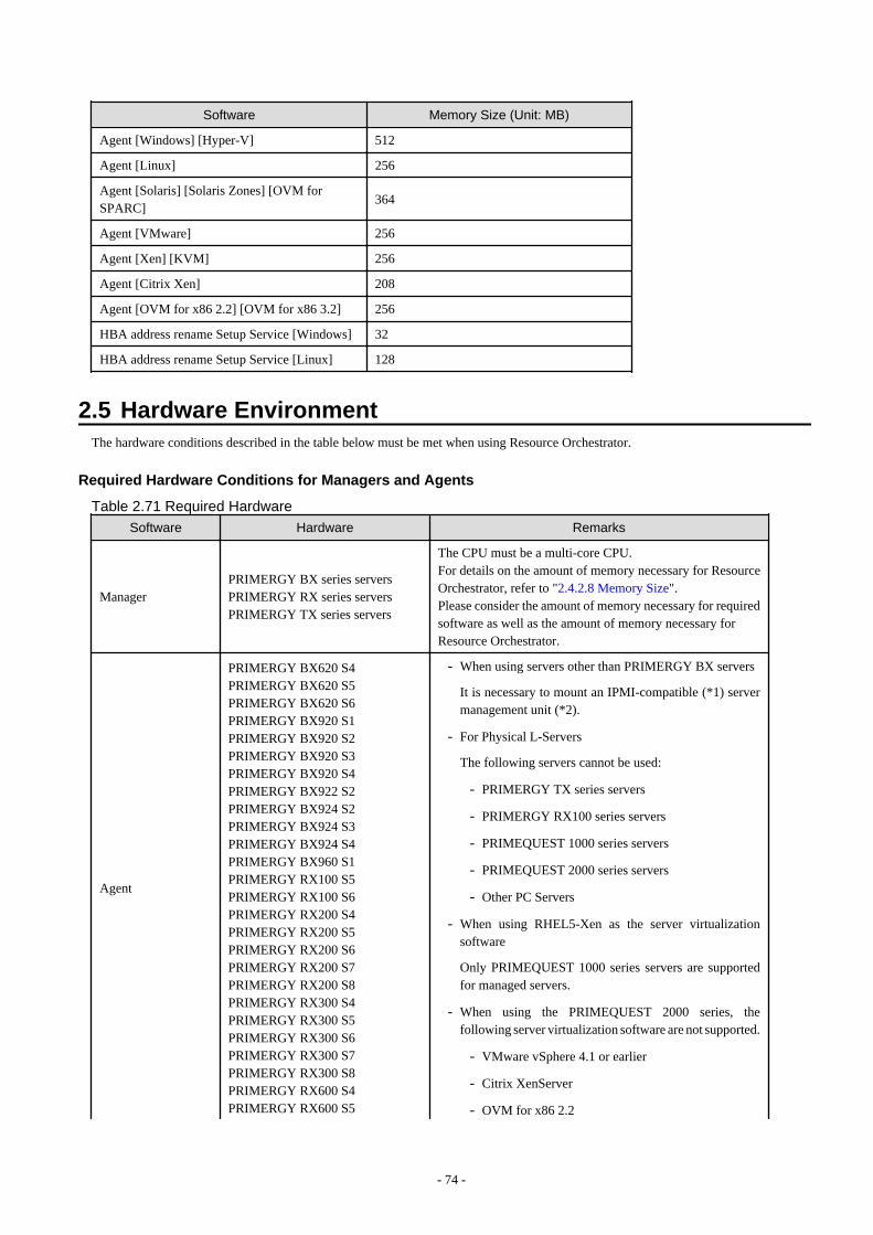
Software Memory Size (Unit: MB)
Agent [Windows] [Hyper-V] 512
Agent [Linux] 256
Agent [Solaris] [Solaris Zones] [OVM forSPARC]
364
Agent [VMware] 256
Agent [Xen] [KVM] 256
Agent [Citrix Xen] 208
Agent [OVM for x86 2.2] [OVM for x86 3.2] 256
HBA address rename Setup Service [Windows] 32
HBA address rename Setup Service [Linux] 128
2.5 Hardware EnvironmentThe hardware conditions described in the table below must be met when using Resource Orchestrator.
Required Hardware Conditions for Managers and Agents
Table 2.71 Required Hardware
Software Hardware Remarks
ManagerPRIMERGY BX series serversPRIMERGY RX series serversPRIMERGY TX series servers
The CPU must be a multi-core CPU.For details on the amount of memory necessary for ResourceOrchestrator, refer to "2.4.2.8 Memory Size".Please consider the amount of memory necessary for requiredsoftware as well as the amount of memory necessary forResource Orchestrator.
Agent
PRIMERGY BX620 S4PRIMERGY BX620 S5PRIMERGY BX620 S6PRIMERGY BX920 S1PRIMERGY BX920 S2PRIMERGY BX920 S3PRIMERGY BX920 S4PRIMERGY BX922 S2PRIMERGY BX924 S2PRIMERGY BX924 S3PRIMERGY BX924 S4PRIMERGY BX960 S1PRIMERGY RX100 S5PRIMERGY RX100 S6PRIMERGY RX200 S4PRIMERGY RX200 S5PRIMERGY RX200 S6PRIMERGY RX200 S7PRIMERGY RX200 S8PRIMERGY RX300 S4PRIMERGY RX300 S5PRIMERGY RX300 S6PRIMERGY RX300 S7PRIMERGY RX300 S8PRIMERGY RX600 S4PRIMERGY RX600 S5
- When using servers other than PRIMERGY BX servers
It is necessary to mount an IPMI-compatible (*1) servermanagement unit (*2).
- For Physical L-Servers
The following servers cannot be used:
- PRIMERGY TX series servers
- PRIMERGY RX100 series servers
- PRIMEQUEST 1000 series servers
- PRIMEQUEST 2000 series servers
- Other PC Servers
- When using RHEL5-Xen as the server virtualizationsoftware
Only PRIMEQUEST 1000 series servers are supportedfor managed servers.
- When using the PRIMEQUEST 2000 series, thefollowing server virtualization software are not supported.
- VMware vSphere 4.1 or earlier
- Citrix XenServer
- OVM for x86 2.2
- 74 -
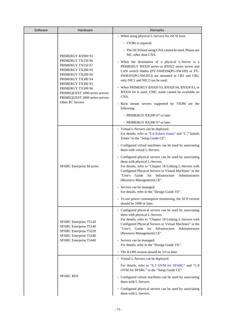
Software Hardware Remarks
PRIMERGY RX900 S1PRIMERGY TX150 S6PRIMERGY TX150 S7PRIMERGY TX200 S5PRIMERGY TX200 S6PRIMERGY TX300 S4PRIMERGY TX300 S5PRIMERGY TX300 S6PRIMEQUEST 1000 series serversPRIMEQUEST 2000 series serversOther PC Servers
- When using physical L-Servers for iSCSI boot
- VIOM is required.
- The iSCSI boot using CNA cannot be used. Please useNIC other than CNA.
- When the destination of a physical L-Server is aPRIMERGY BX920 series or BX922 series server andLAN switch blades (PY-SWB104(PG-SW109) or PY-SWB101(PG-SW201)) are mounted in CB1 and CB2,only NIC1 and NIC2 can be used.
- When PRIMERGY BX920 S3, BX920 S4, BX924 S3, orBX924 S4 is used, UMC mode cannot be available onCNA.
- Rack mount servers supported by VIOM are thefollowing:
- PRIMERGY RX200 S7 or later
- PRIMERGY RX300 S7 or later
SPARC Enterprise M series
- Virtual L-Servers can be deployed.For details, refer to "E.6 Solaris Zones" and "C.7 SolarisZones" in the "Setup Guide CE".
- Configured virtual machines can be used by associatingthem with virtual L-Servers.
- Configured physical servers can be used by associatingthem with physical L-Servers.For details, refer to "Chapter 18 Linking L-Servers withConfigured Physical Servers or Virtual Machines" in the"User's Guide for Infrastructure Administrators(Resource Management) CE".
- Servers can be managed.For details, refer to the "Design Guide VE".
- To use power consumption monitoring, the XCP versionshould be 1090 or later.
SPARC Enterprise T5120SPARC Enterprise T5140SPARC Enterprise T5220SPARC Enterprise T5240SPARC Enterprise T5440
- Configured physical servers can be used by associatingthem with physical L-Servers.For details, refer to "Chapter 18 Linking L-Servers withConfigured Physical Servers or Virtual Machines" in the"User's Guide for Infrastructure Administrators(Resource Management) CE".
- Servers can be managed.For details, refer to the "Design Guide VE".
- The ILOM version should be 3.0 or later.
SPARC M10
- Virtual L-Servers can be deployed.
For details, refer to "E.7 OVM for SPARC" and "C.8OVM for SPARC" in the "Setup Guide CE".
- Configured virtual machines can be used by associatingthem with L-Servers.
- Configured physical servers can be used by associatingthem with L-Servers.
- 75 -
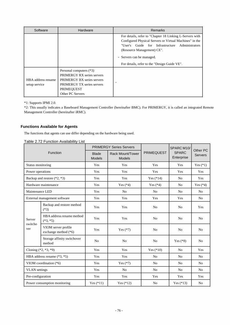
Software Hardware Remarks
For details, refer to "Chapter 18 Linking L-Servers withConfigured Physical Servers or Virtual Machines" in the"User's Guide for Infrastructure Administrators(Resource Management) CE".
- Servers can be managed.
For details, refer to the "Design Guide VE".
HBA address renamesetup service
Personal computers (*3)PRIMERGY RX series serversPRIMERGY BX series serversPRIMERGY TX series serversPRIMEQUESTOther PC Servers
-
*1: Supports IPMI 2.0.*2: This usually indicates a Baseboard Management Controller (hereinafter BMC). For PRIMERGY, it is called an integrated RemoteManagement Controller (hereinafter iRMC).
Functions Available for Agents
The functions that agents can use differ depending on the hardware being used.
Table 2.72 Function Availability List
Function
PRIMERGY Series Servers
PRIMEQUESTSPARC M10/
SPARCEnterprise
Other PCServersBlade
ModelsRack Mount/Tower
Models
Status monitoring Yes Yes Yes Yes Yes (*1)
Power operations Yes Yes Yes Yes Yes
Backup and restore (*2, *3) Yes Yes Yes (*14) No Yes
Hardware maintenance Yes Yes (*4) Yes (*4) No Yes (*4)
Maintenance LED Yes No No No No
External management software Yes Yes Yes Yes No
Serverswitchover
Backup and restore method(*3)
Yes Yes No No Yes
HBA address rename method(*3, *5)
Yes Yes No No No
VIOM server profileexchange method (*6)
Yes Yes (*7) No No No
Storage affinity switchovermethod
No No No Yes (*8) No
Cloning (*2, *3, *9) Yes Yes Yes (*10) No Yes
HBA address rename (*3, *5) Yes Yes No No No
VIOM coordination (*6) Yes Yes (*7) No No No
VLAN settings Yes No No No No
Pre-configuration Yes Yes Yes Yes Yes
Power consumption monitoring Yes (*11) Yes (*12) No Yes (*13) No
- 76 -
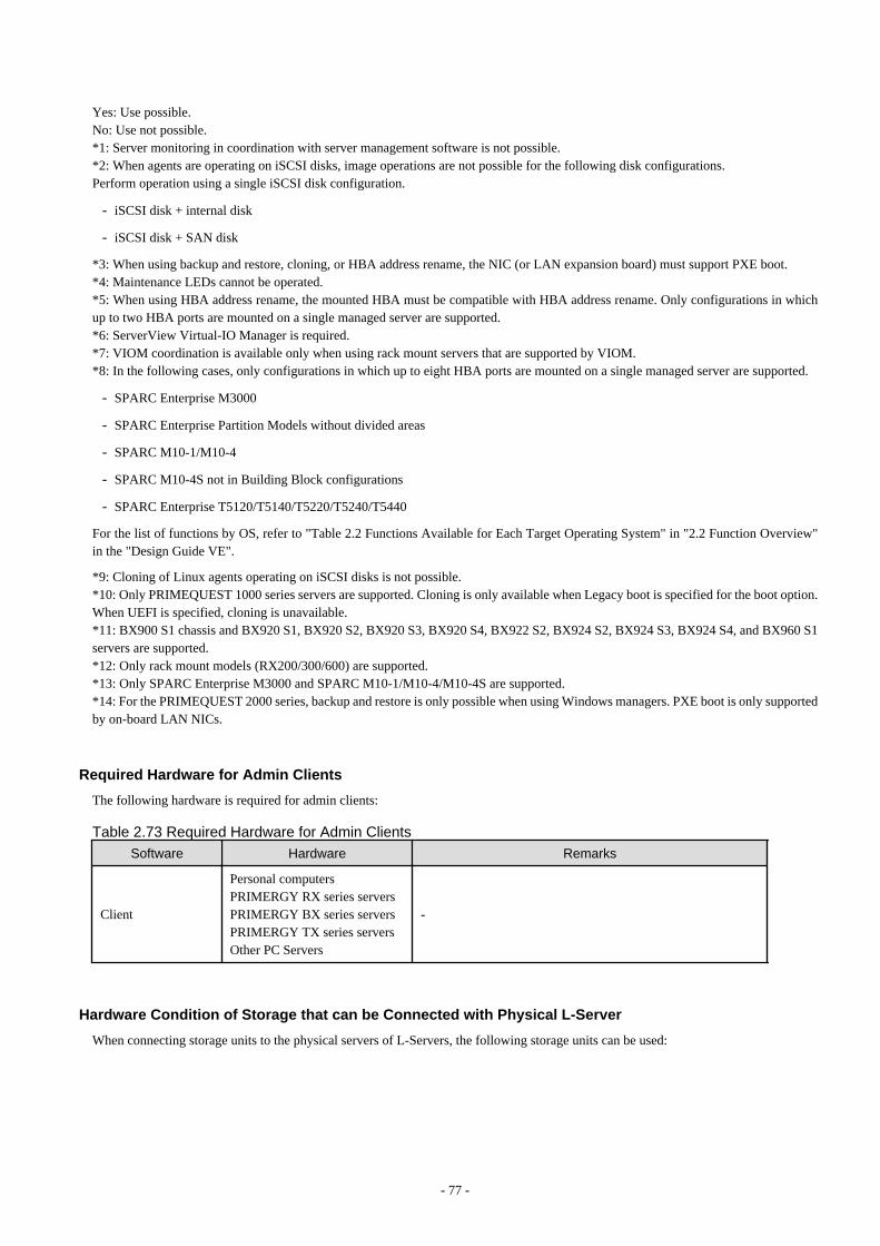
Yes: Use possible.No: Use not possible.*1: Server monitoring in coordination with server management software is not possible.*2: When agents are operating on iSCSI disks, image operations are not possible for the following disk configurations.Perform operation using a single iSCSI disk configuration.
- iSCSI disk + internal disk
- iSCSI disk + SAN disk
*3: When using backup and restore, cloning, or HBA address rename, the NIC (or LAN expansion board) must support PXE boot.*4: Maintenance LEDs cannot be operated.*5: When using HBA address rename, the mounted HBA must be compatible with HBA address rename. Only configurations in whichup to two HBA ports are mounted on a single managed server are supported.*6: ServerView Virtual-IO Manager is required.*7: VIOM coordination is available only when using rack mount servers that are supported by VIOM.*8: In the following cases, only configurations in which up to eight HBA ports are mounted on a single managed server are supported.
- SPARC Enterprise M3000
- SPARC Enterprise Partition Models without divided areas
- SPARC M10-1/M10-4
- SPARC M10-4S not in Building Block configurations
- SPARC Enterprise T5120/T5140/T5220/T5240/T5440
For the list of functions by OS, refer to "Table 2.2 Functions Available for Each Target Operating System" in "2.2 Function Overview"in the "Design Guide VE".
*9: Cloning of Linux agents operating on iSCSI disks is not possible.*10: Only PRIMEQUEST 1000 series servers are supported. Cloning is only available when Legacy boot is specified for the boot option.When UEFI is specified, cloning is unavailable.*11: BX900 S1 chassis and BX920 S1, BX920 S2, BX920 S3, BX920 S4, BX922 S2, BX924 S2, BX924 S3, BX924 S4, and BX960 S1servers are supported.*12: Only rack mount models (RX200/300/600) are supported.*13: Only SPARC Enterprise M3000 and SPARC M10-1/M10-4/M10-4S are supported.*14: For the PRIMEQUEST 2000 series, backup and restore is only possible when using Windows managers. PXE boot is only supportedby on-board LAN NICs.
Required Hardware for Admin Clients
The following hardware is required for admin clients:
Table 2.73 Required Hardware for Admin Clients
Software Hardware Remarks
Client
Personal computersPRIMERGY RX series serversPRIMERGY BX series serversPRIMERGY TX series serversOther PC Servers
-
Hardware Condition of Storage that can be Connected with Physical L-Server
When connecting storage units to the physical servers of L-Servers, the following storage units can be used:
- 77 -
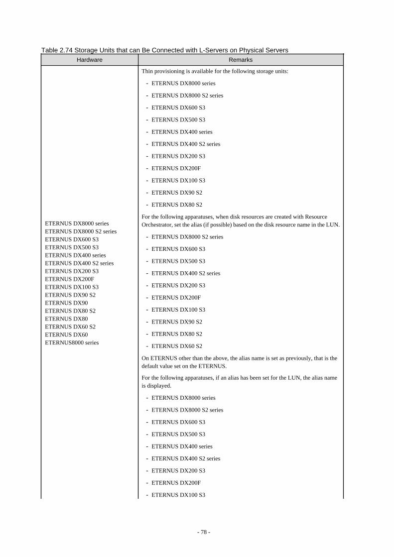
Table 2.74 Storage Units that can Be Connected with L-Servers on Physical ServersHardware Remarks
ETERNUS DX8000 seriesETERNUS DX8000 S2 seriesETERNUS DX600 S3ETERNUS DX500 S3ETERNUS DX400 seriesETERNUS DX400 S2 seriesETERNUS DX200 S3ETERNUS DX200FETERNUS DX100 S3ETERNUS DX90 S2ETERNUS DX90ETERNUS DX80 S2ETERNUS DX80ETERNUS DX60 S2ETERNUS DX60ETERNUS8000 series
Thin provisioning is available for the following storage units:
- ETERNUS DX8000 series
- ETERNUS DX8000 S2 series
- ETERNUS DX600 S3
- ETERNUS DX500 S3
- ETERNUS DX400 series
- ETERNUS DX400 S2 series
- ETERNUS DX200 S3
- ETERNUS DX200F
- ETERNUS DX100 S3
- ETERNUS DX90 S2
- ETERNUS DX80 S2
For the following apparatuses, when disk resources are created with ResourceOrchestrator, set the alias (if possible) based on the disk resource name in the LUN.
- ETERNUS DX8000 S2 series
- ETERNUS DX600 S3
- ETERNUS DX500 S3
- ETERNUS DX400 S2 series
- ETERNUS DX200 S3
- ETERNUS DX200F
- ETERNUS DX100 S3
- ETERNUS DX90 S2
- ETERNUS DX80 S2
- ETERNUS DX60 S2
On ETERNUS other than the above, the alias name is set as previously, that is thedefault value set on the ETERNUS.
For the following apparatuses, if an alias has been set for the LUN, the alias nameis displayed.
- ETERNUS DX8000 series
- ETERNUS DX8000 S2 series
- ETERNUS DX600 S3
- ETERNUS DX500 S3
- ETERNUS DX400 series
- ETERNUS DX400 S2 series
- ETERNUS DX200 S3
- ETERNUS DX200F
- ETERNUS DX100 S3
- 78 -
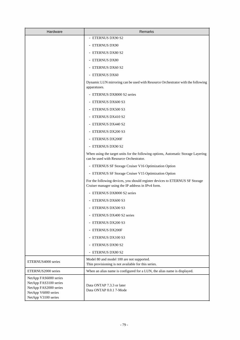
Hardware Remarks
- ETERNUS DX90 S2
- ETERNUS DX90
- ETERNUS DX80 S2
- ETERNUS DX80
- ETERNUS DX60 S2
- ETERNUS DX60
Dynamic LUN mirroring can be used with Resource Orchestrator with the followingapparatuses.
- ETERNUS DX8000 S2 series
- ETERNUS DX600 S3
- ETERNUS DX500 S3
- ETERNUS DX410 S2
- ETERNUS DX440 S2
- ETERNUS DX200 S3
- ETERNUS DX200F
- ETERNUS DX90 S2
When using the target units for the following options, Automatic Storage Layeringcan be used with Resource Orchestrator.
- ETERNUS SF Storage Cruiser V16 Optimization Option
- ETERNUS SF Storage Cruiser V15 Optimization Option
For the following devices, you should register devices to ETERNUS SF StorageCruiser manager using the IP address in IPv4 form.
- ETERNUS DX8000 S2 series
- ETERNUS DX600 S3
- ETERNUS DX500 S3
- ETERNUS DX400 S2 series
- ETERNUS DX200 S3
- ETERNUS DX200F
- ETERNUS DX100 S3
- ETERNUS DX90 S2
- ETERNUS DX80 S2
ETERNUS4000 seriesModel 80 and model 100 are not supported.Thin provisioning is not available for this series.
ETERNUS2000 series When an alias name is configured for a LUN, the alias name is displayed.
NetApp FAS6000 seriesNetApp FAS3100 seriesNetApp FAS2000 seriesNetApp V6000 seriesNetApp V3100 series
Data ONTAP 7.3.3 or laterData ONTAP 8.0.1 7-Mode
- 79 -

Hardware Remarks
EMC CLARiiON CX4-120EMC CLARiiON CX4-240EMC CLARiiON CX4-480EMC CLARiiON CX4-960EMC CLARiiON CX3-10EMC CLARiiON CX3-20EMC CLARiiON CX3-40EMC CLARiiON CX3-80EMC VNX5100EMC VNX5300EMC VNX5500EMC VNX5700EMC VNX7500
Navisphere Manager and Access Logix must be installed on SP.
EMC Symmetrix DMX-3EMC Symmetrix DMX-4EMC Symmetrix VMAX
VolumeLogix must be installed on SP.
Storage Server on which FalconStorNSS operates
It should be a model on which FalconStor guarantees the operation of FalconStorNSS.Please install FalconStor NSS in Storage Server.The following versions of FalconStor NSS are supported.
- V7.00
Storage unit connected with StorageServer on which FalconStor NSSoperates
It should be a model on which FalconStor guarantees the operation of FalconStorNSS.
Fiber channel switch connected withStorage Server on which FalconStorNSS operates
It should be a model on which FalconStor guarantees the operation of FalconStorNSS.
When using storage management software, do not change or delete the content set for storage units by Resource Orchestrator.
When connecting storage units to the physical servers of L-Servers, the following Fibre Channel switches can be used:
Table 2.75 Fibre Channel Switches which can be Used when Connecting Storage Units with L-Servers onPhysical Servers
Hardware Remarks
Brocade seriesETERNUS SN200 series
-
PRIMERGY BX600 Fibre Channelswitch blades
Connect fibre channel switch blades to the following connection blades:
- NET3, NET4
PRIMERGY BX900 Fibre Channelswitch blades
Connect fibre channel switch blades to the following connection blades:
- CB5, CB6
PRIMERGY BX400 Fibre Channelswitch blades
Connect fibre channel switch blades to the following connection blades:
- CB3, CB4
Hardware Conditions of Storage that can be Connected to Virtual L-Servers
When connecting storage units to virtual L-Servers, the following storage units can be used:
[VMware]Refer to "Supported Storage Configurations" in "E.1.3 Storage Preparations".
- 80 -
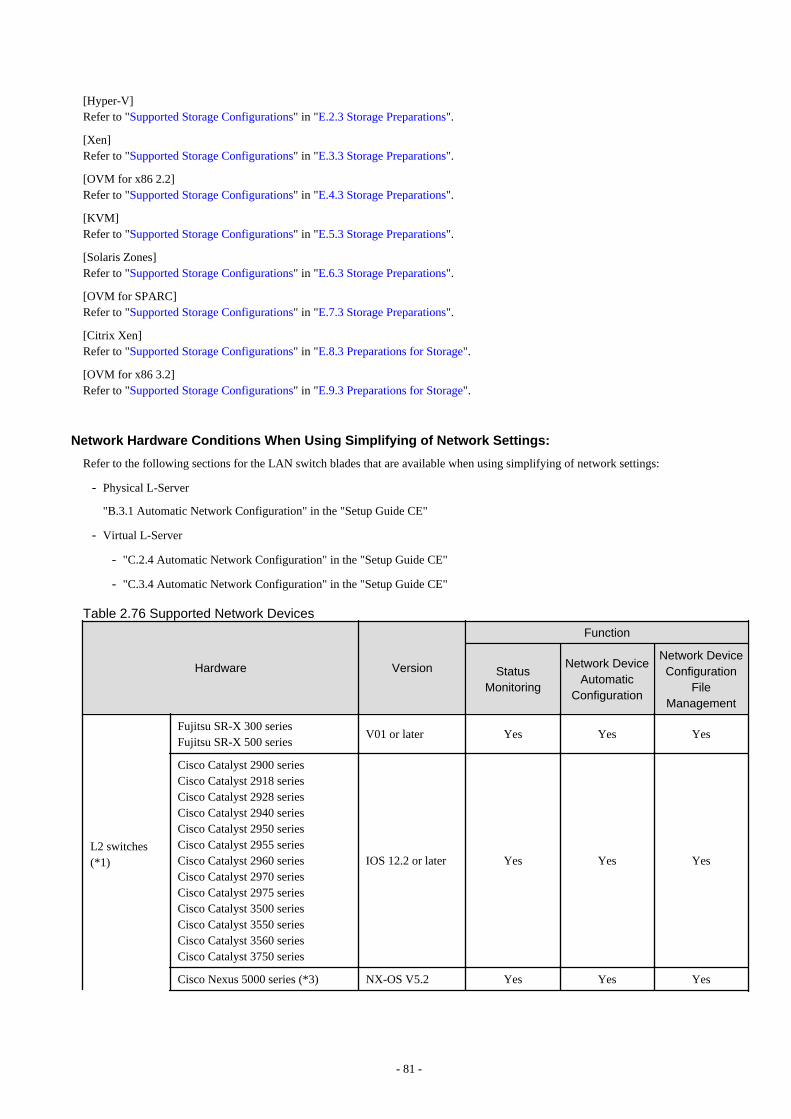
[Hyper-V]Refer to "Supported Storage Configurations" in "E.2.3 Storage Preparations".
[Xen]Refer to "Supported Storage Configurations" in "E.3.3 Storage Preparations".
[OVM for x86 2.2]Refer to "Supported Storage Configurations" in "E.4.3 Storage Preparations".
[KVM]Refer to "Supported Storage Configurations" in "E.5.3 Storage Preparations".
[Solaris Zones]Refer to "Supported Storage Configurations" in "E.6.3 Storage Preparations".
[OVM for SPARC]Refer to "Supported Storage Configurations" in "E.7.3 Storage Preparations".
[Citrix Xen]Refer to "Supported Storage Configurations" in "E.8.3 Preparations for Storage".
[OVM for x86 3.2]Refer to "Supported Storage Configurations" in "E.9.3 Preparations for Storage".
Network Hardware Conditions When Using Simplifying of Network Settings:
Refer to the following sections for the LAN switch blades that are available when using simplifying of network settings:
- Physical L-Server
"B.3.1 Automatic Network Configuration" in the "Setup Guide CE"
- Virtual L-Server
- "C.2.4 Automatic Network Configuration" in the "Setup Guide CE"
- "C.3.4 Automatic Network Configuration" in the "Setup Guide CE"
Table 2.76 Supported Network Devices
Hardware Version
Function
StatusMonitoring
Network DeviceAutomatic
Configuration
Network DeviceConfiguration
FileManagement
L2 switches(*1)
Fujitsu SR-X 300 seriesFujitsu SR-X 500 series
V01 or later Yes Yes Yes
Cisco Catalyst 2900 seriesCisco Catalyst 2918 seriesCisco Catalyst 2928 seriesCisco Catalyst 2940 seriesCisco Catalyst 2950 seriesCisco Catalyst 2955 seriesCisco Catalyst 2960 seriesCisco Catalyst 2970 seriesCisco Catalyst 2975 seriesCisco Catalyst 3500 seriesCisco Catalyst 3550 seriesCisco Catalyst 3560 seriesCisco Catalyst 3750 series
IOS 12.2 or later Yes Yes Yes
Cisco Nexus 5000 series (*3) NX-OS V5.2 Yes Yes Yes
- 81 -
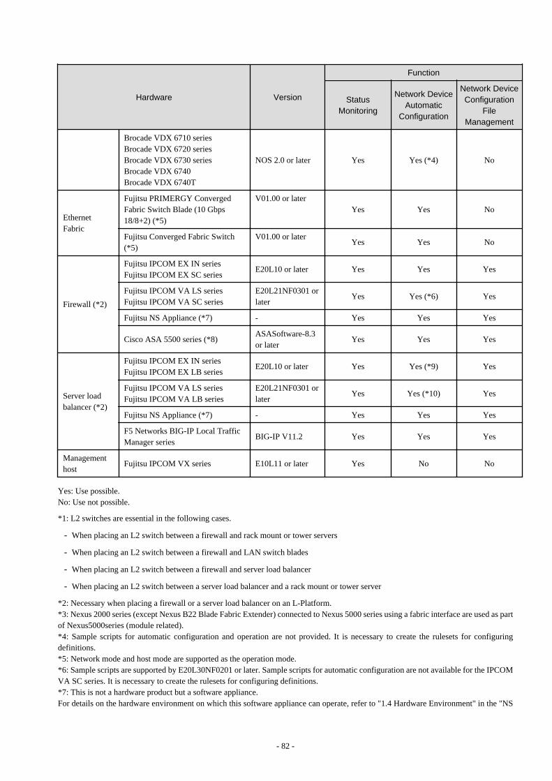
Hardware Version
Function
StatusMonitoring
Network DeviceAutomatic
Configuration
Network DeviceConfiguration
FileManagement
Brocade VDX 6710 seriesBrocade VDX 6720 seriesBrocade VDX 6730 seriesBrocade VDX 6740Brocade VDX 6740T
NOS 2.0 or later Yes Yes (*4) No
EthernetFabric
Fujitsu PRIMERGY ConvergedFabric Switch Blade (10 Gbps18/8+2) (*5)
V01.00 or laterYes Yes No
Fujitsu Converged Fabric Switch(*5)
V01.00 or laterYes Yes No
Firewall (*2)
Fujitsu IPCOM EX IN seriesFujitsu IPCOM EX SC series
E20L10 or later Yes Yes Yes
Fujitsu IPCOM VA LS seriesFujitsu IPCOM VA SC series
E20L21NF0301 orlater
Yes Yes (*6) Yes
Fujitsu NS Appliance (*7) - Yes Yes Yes
Cisco ASA 5500 series (*8)ASASoftware-8.3or later
Yes Yes Yes
Server loadbalancer (*2)
Fujitsu IPCOM EX IN seriesFujitsu IPCOM EX LB series
E20L10 or later Yes Yes (*9) Yes
Fujitsu IPCOM VA LS seriesFujitsu IPCOM VA LB series
E20L21NF0301 orlater
Yes Yes (*10) Yes
Fujitsu NS Appliance (*7) - Yes Yes Yes
F5 Networks BIG-IP Local TrafficManager series
BIG-IP V11.2 Yes Yes Yes
Managementhost
Fujitsu IPCOM VX series E10L11 or later Yes No No
Yes: Use possible.No: Use not possible.
*1: L2 switches are essential in the following cases.
- When placing an L2 switch between a firewall and rack mount or tower servers
- When placing an L2 switch between a firewall and LAN switch blades
- When placing an L2 switch between a firewall and server load balancer
- When placing an L2 switch between a server load balancer and a rack mount or tower server
*2: Necessary when placing a firewall or a server load balancer on an L-Platform.*3: Nexus 2000 series (except Nexus B22 Blade Fabric Extender) connected to Nexus 5000 series using a fabric interface are used as partof Nexus5000series (module related).*4: Sample scripts for automatic configuration and operation are not provided. It is necessary to create the rulesets for configuringdefinitions.*5: Network mode and host mode are supported as the operation mode.*6: Sample scripts are supported by E20L30NF0201 or later. Sample scripts for automatic configuration are not available for the IPCOMVA SC series. It is necessary to create the rulesets for configuring definitions.*7: This is not a hardware product but a software appliance.For details on the hardware environment on which this software appliance can operate, refer to "1.4 Hardware Environment" in the "NS
- 82 -
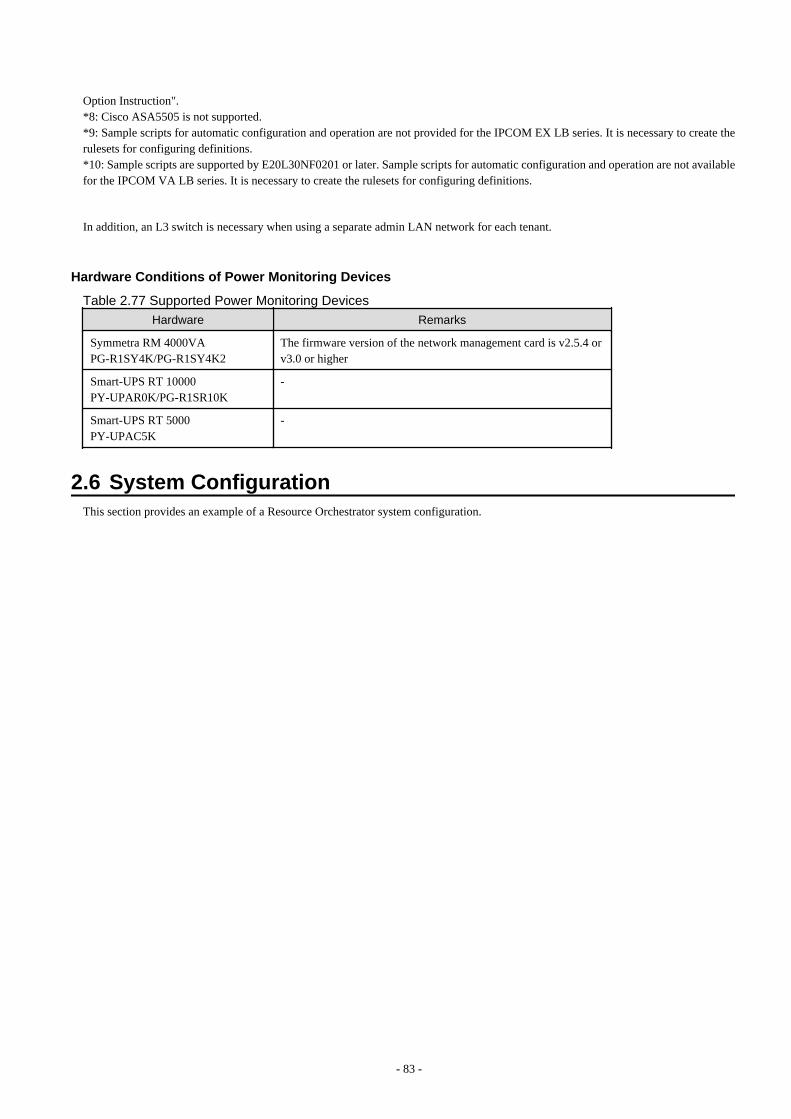
Option Instruction".*8: Cisco ASA5505 is not supported.*9: Sample scripts for automatic configuration and operation are not provided for the IPCOM EX LB series. It is necessary to create therulesets for configuring definitions.*10: Sample scripts are supported by E20L30NF0201 or later. Sample scripts for automatic configuration and operation are not availablefor the IPCOM VA LB series. It is necessary to create the rulesets for configuring definitions.
In addition, an L3 switch is necessary when using a separate admin LAN network for each tenant.
Hardware Conditions of Power Monitoring Devices
Table 2.77 Supported Power Monitoring Devices
Hardware Remarks
Symmetra RM 4000VAPG-R1SY4K/PG-R1SY4K2
The firmware version of the network management card is v2.5.4 orv3.0 or higher
Smart-UPS RT 10000 PY-UPAR0K/PG-R1SR10K
-
Smart-UPS RT 5000 PY-UPAC5K
-
2.6 System ConfigurationThis section provides an example of a Resource Orchestrator system configuration.
- 83 -
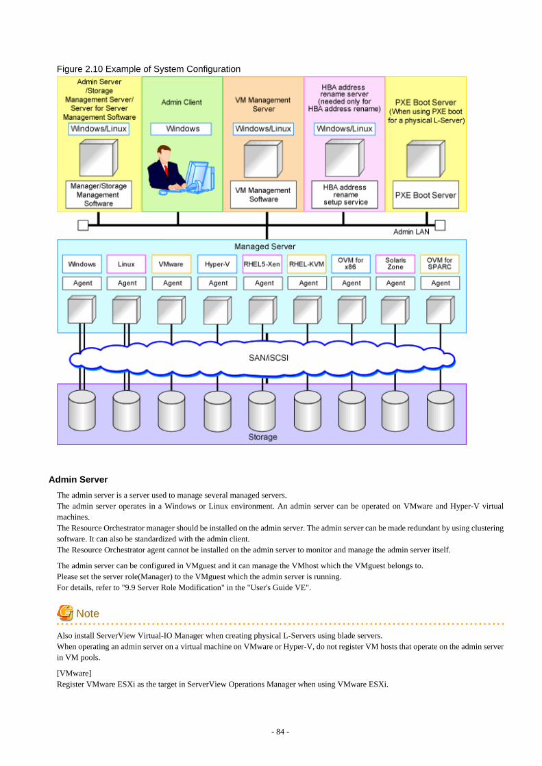
Figure 2.10 Example of System Configuration
Admin Server
The admin server is a server used to manage several managed servers.The admin server operates in a Windows or Linux environment. An admin server can be operated on VMware and Hyper-V virtualmachines.The Resource Orchestrator manager should be installed on the admin server. The admin server can be made redundant by using clusteringsoftware. It can also be standardized with the admin client.The Resource Orchestrator agent cannot be installed on the admin server to monitor and manage the admin server itself.
The admin server can be configured in VMguest and it can manage the VMhost which the VMguest belongs to.Please set the server role(Manager) to the VMguest which the admin server is running.For details, refer to "9.9 Server Role Modification" in the "User's Guide VE".
Note
Also install ServerView Virtual-IO Manager when creating physical L-Servers using blade servers.When operating an admin server on a virtual machine on VMware or Hyper-V, do not register VM hosts that operate on the admin serverin VM pools.
[VMware]Register VMware ESXi as the target in ServerView Operations Manager when using VMware ESXi.
- 84 -

[Hyper-V]When using Hyper-V on managed servers, the only supported OS of the admin server is Windows.
[Xen]When using RHEL5-Xen on managed servers, the only supported OS of the admin server is Linux.
Managed Server
Managed servers are the servers used to run applications. They are managed by the admin server.
Managed servers are primary servers operating in the following environments.
- Windows Environments
- Linux Environments
- Solaris Environments
- Server Virtualization Software Environments
For details on the types of server virtualization software, refer to "11.1 Deciding Server Virtualization Software".
Install agents on managed servers.In server virtualization environments, the agent should only be installed on the VM host.
Note
When using VMware ESXi, there is no need to install Resource Orchestrator agents on managed servers because VMs and guest OSs aremanaged directly from the admin server.Install ServerView ESXi CIM Provider.
When using other vendor's servers, perform "C.1.5 Configuration when Creating a Virtual L-Server Using VMware ESXi on OtherVendor's Servers" in the "Setup Guide CE".
[Windows]
- Depending on the domain type, there may be cases in which backup and restore, cloning, and server switchover using the backup andrestore method cannot be used, or additional operations on managed servers are necessary.
Table 2.78 Function Restrictions Based on Domain Type
Domain Type Backup and Restore CloningServer Switchover Using Backup and
Restore
Domain controller No No No
Member server (*1) Yes (*2) Yes (*2, *3) Yes (*2, *4)
Workgroup Yes Yes Yes
Yes: Use possible.No: Use not possible.*1: Member servers of Windows NT domains or Active Directory.*2: After performing operations, it is necessary to join Windows NT domains or Active Directory again.*3: Before obtaining cloning images, ensure that the server is not a member of a Windows NT domain or Active Directory.*4: When switchover has been performed using Auto-Recovery, join Windows NT domains or Active Directory again before startingoperations.
- When the domain type is domain controller, agents cannot be installed while the status promoted to domain controller.
- When the domain type is member server or work group, agents can be installed when logged in using a local account that belongs tothe Administrators group.
- 85 -

Admin Client
Admin clients are terminals used to connect to the admin server, which can be used to monitor and control the configuration and status ofthe entire system.Admin clients should run in a Windows environment.
Install Web browsers on admin clients.If a server virtualization software client is installed on an admin client, the software can be started from the client screen of ResourceOrchestrator.
Storage Management Server
A server on which storage management software that manages multiple storage units has been installed.
Sharing with the admin server differs depending on the storage in use.
- When using ETERNUS storage
- Operate ETERNUS SF Storage Cruiser in the same environments as the admin server.Note that resources for both the admin and storage management software servers are required when operating the servers together.
- Operate the ETERNUS SF AdvancedCopy Manager Copy Control Module in the same environment as the admin server.
- When using NetApp storage
In Resource Orchestrator, Data ONTAP can be used as storage management software, but a server for storage management softwareis not necessary, as Data ONTAP is an OS for NetApp storage.
- When using EMC CLARiiON storage or EMC VNX storage
In Resource Orchestrator, Navisphere can be used as storage management software, but no server is necessary for storage managementsoftware, as Navisphere operates on the Storage Processor (hereinafter SP) of EMC CLARiiON storage or EMC VNX storage.
- When using EMC Symmetrix DMX storage or EMC Symmetrix VMAX storage
In Resource Orchestrator, Solutions Enabler can be used as storage management software. Servers for storage management softwarecan be operated on the same computer as the admin server, but the storage management software must be connected to EMC SymmetrixDMX storage or EMC Symmetrix VMAX storage using FC-HBA. Note that resources for both the admin and storage managementsoftware servers are required when operating the servers together.
- When using Storage Server on which FalconStor NSS operates
In Resource Orchestrator, FalconStor NSS can be used as storage management software. Install FalconStor NSS on the Storage Server.FalconStor NSS cannot be installed on the admin server.
VM Management Server
A server on which VM management software to integrate multiple server virtualization software products has been installed.For details on the VM management software which can be registered in Resource Orchestrator, refer to "5.2 Registering VM ManagementSoftware" in the "User's Guide for Infrastructure Administrators (Resource Management) CE".The VM management server can be operated on the same machine as the admin server.
Note that resources for both the admin and VM management servers are required when operating the servers together.
Server Management Server
A server on which server management software that manages multiple servers has been installed.
- When using BMC BladeLogic Server Automation [Solaris Zones] [OVM for SPARC]
- Necessary when using the functions with "Yes (*)" described in "Table 11.1 Functional Differences Depending on ServerVirtualization Software" in "Chapter 11 Deciding and Configuring Server Virtualization Software".
- 86 -
- Can be placed on the same server as the manager (recommended) or on another server.
When operating managers in clusters, place it on a different server.
SMTP Server
An SMTP server is necessary to send notification to users using e-mail.It can be placed on the same server as an admin server or on another server.
PXE Boot Server
For purposes such as OS installation, it is necessary to perform PXE boot of a physical L-Server using its own PXE server.
The PXE boot server must be operated on a server other than the admin server.
Note
PXE boot is unavailable on networks that use tagged VLAN settings.
Do not configure tagged VLANs for PXE boot servers.
HBA address rename Setup Service Server
A server on which the HBA address rename setup service operates.This is necessary when creating physical L-Servers using HBA address rename for I/O virtualization.This is not necessary when creating physical L-Servers using blade servers.When an admin server cannot be communicated with from a managed server, configure the necessary WWNs for starting the managedserver instead of the admin server.The HBA address rename server operates in a Windows or Linux environment.Install the HBA address rename setup service online this server.It is not possible to use the HBA address rename server as an admin server and a managed server at the same time.Keep this server powered ON at all times, in preparation for admin server trouble or communication errors.For details, refer to "10.1.3 HBA and Storage Device Settings" and "C.2 WWN Allocation Order during HBA address renameConfiguration".
Admin LAN
The admin LAN is the LAN used by the admin server to control managed servers and storage.The admin LAN is set up separately from the public LAN used by applications on managed servers.Using network redundancy software on the server enables redundancy for the admin LAN or the public LAN. Manually configure networkredundancy software.
When using a physical L-Server, the default physical network adapter numbers available for the admin LAN are as given below.
- When not performing redundancy, "1" is available
- When performing redundancy, "1" and "2" are available
Note
When using a NIC other than the default one, the configuration at the time of physical server registration and at L-Server creation mustbe the same. Thus when designing systems it is recommended that physical servers registered in the same server pool use the same NICindex.
- 87 -

Information
The first NIC that is available for the admin LAN can be changed.For details, refer to "5.4.2 Registering Blade Servers" in the "User's Guide for Infrastructure Administrators (Resource Management) CE".
iSCSI LAN
Refer to "9.1.3 Physical Network Design for the Public LAN and iSCSI LAN".
- 88 -
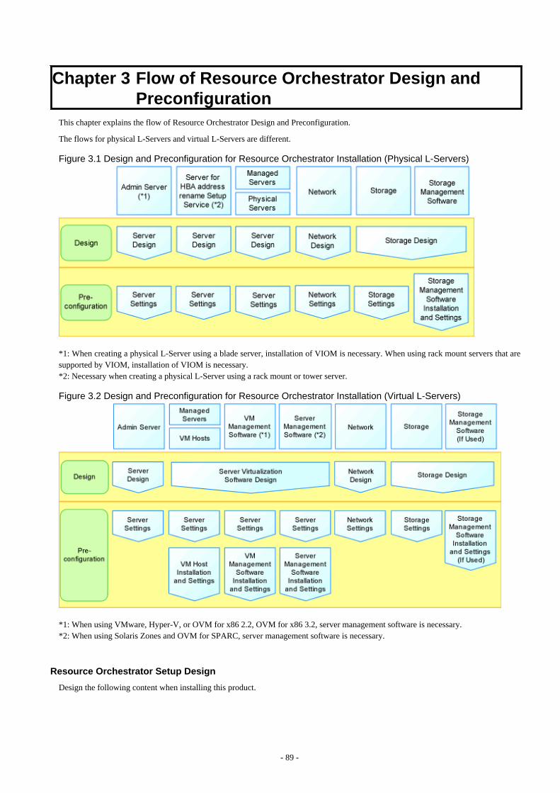
Chapter 3 Flow of Resource Orchestrator Design andPreconfiguration
This chapter explains the flow of Resource Orchestrator Design and Preconfiguration.
The flows for physical L-Servers and virtual L-Servers are different.
Figure 3.1 Design and Preconfiguration for Resource Orchestrator Installation (Physical L-Servers)
*1: When creating a physical L-Server using a blade server, installation of VIOM is necessary. When using rack mount servers that aresupported by VIOM, installation of VIOM is necessary.*2: Necessary when creating a physical L-Server using a rack mount or tower server.
Figure 3.2 Design and Preconfiguration for Resource Orchestrator Installation (Virtual L-Servers)
*1: When using VMware, Hyper-V, or OVM for x86 2.2, OVM for x86 3.2, server management software is necessary.*2: When using Solaris Zones and OVM for SPARC, server management software is necessary.
Resource Orchestrator Setup Design
Design the following content when installing this product.
- 89 -
- System Configuration Design
For details, refer to "Chapter 4 System Configuration Design".
- Defining User Accounts
For details, refer to "Chapter 5 Defining User Accounts".
- Defining Tenant and Resource Pools
For details, refer to "Chapter 6 Defining Tenants and Resource Pools".
- When Using Converged Fabrics
Designing of tenants may be required because they are managed in a different way from the other network devices.For details, refer to "H.1 Fujitsu PRIMERGY Converged Fabric Switch Blade (10 Gbps 18/8+2) and Fujitsu Converged FabricSwitch".
- When Using IPCOM VX/VA
Designing of tenants may be required because they are managed in a different way from the other network devices.For details, refer to "Appendix J IPCOM VX Series Devices".
- Defining High Availability and Disaster Recovery
Refer to "Chapter 7 Defining High Availability and Disaster Recovery".
- Defining the Server Environment
Define the server environment to manage with the admin server and this product.
For details, refer to "8.1 Defining the Server Environment".
- Defining the Network Environment
For details, refer to "Chapter 9 Defining and Configuring the Network Environment".
- Deciding the Storage Environment
For details, refer to "10.1 Deciding the Storage Environment".
- Deciding Server Virtualization Software
Decide the server virtualization software to manage with this product.
For details, refer to "11.1 Deciding Server Virtualization Software".
- Installing and Defining Single Sign-On
decide the single sign-on environment.
Refer to "Chapter 12 Installing and Defining Single Sign-On".
- Deciding the Power Monitoring Environment
For details, refer to "13.1 Deciding the Power Monitoring Environment".
Preconfiguration for a Resource Orchestrator Installation
Preconfiguration is necessary before the manager of this product is installed.
Perform it according to the following procedure.
- Configuring the Server Environment
The server environment managed with the admin server and this product is set.
Refer to "8.2 Configuring the Server Environment".
- Configuring the Network Environment
For details, refer to "Chapter 9 Defining and Configuring the Network Environment".
- 90 -

- Configuring the Storage Environment
For details, refer to "10.2 Configuring the Storage Environment".
- Settings for Server Virtualization Software
Set the server virtualization software managed with this product.
For details, refer to "11.2 Settings for Server Virtualization Software".
- Installing and Defining Single Sign-On
set the single sign-on environment is set.
Refer to "Chapter 12 Installing and Defining Single Sign-On".
- Configuring the Power Monitoring Environment
For details, refer to "13.2 Configuring the Power Monitoring Environment".
- 91 -
Chapter 4 System Configuration DesignThis section explains how to design a system configuration.
L-Server Design
The procedure differs depending on whether the L-Server is physical or virtual.
For details, refer to the following:
- For Physical L-Servers
For details, refer to "D.1 System Configuration".
- For Virtual L-Servers
[VMware]For details, refer to "E.1.1 System Configuration".
[Hyper-V]For details, refer to "E.2.1 System Configuration".
[Xen]For details, refer to "E.3.1 System Configuration".
[OVM for x86 2.2]For details, refer to "E.4.1 System Configuration".
[KVM]For details, refer to "E.5.1 System Configuration".
[Solaris Zones]For details, refer to "E.6.1 System Configuration".
[OVM for SPARC]For details, refer to "E.7.1 System Configuration".
[Citrix Xen]For details, refer to "E.8.1 System Configuration".
[OVM for x86 3.2]For details, refer to "E.9.1 System Configuration".
L-Platform Network Design
For details on L-Platform Network design, refer to "9.1 Defining the Network Environment".
Points to Keep in Mind when Setting Up a Resource Orchestrator Environment
- The maximum of managed servers can be registered in Resource Orchestrator is limited, and depends on the Resource Orchestratorlicense purchased.For details on the limit of managed servers, refer to license documentation.
An error will occur when trying to register more managed servers than the above limit. This limit includes the spare servers used byrecovery settings. However, it does not include VM guests.
- Clustering software can be used on managed servers.
However, the following operations are not supported.
- Managed Server Switchover
- Backup and Restore
- Use of the Windows Server 2008 or later BitLocker drive encryption function (Windows BitLocker Drive Encryption) is not supported.
If the admin server or managed servers are running under Windows Server 2008 or later, do not encrypt the system disk using theBitLocker drive encryption function.
- 92 -
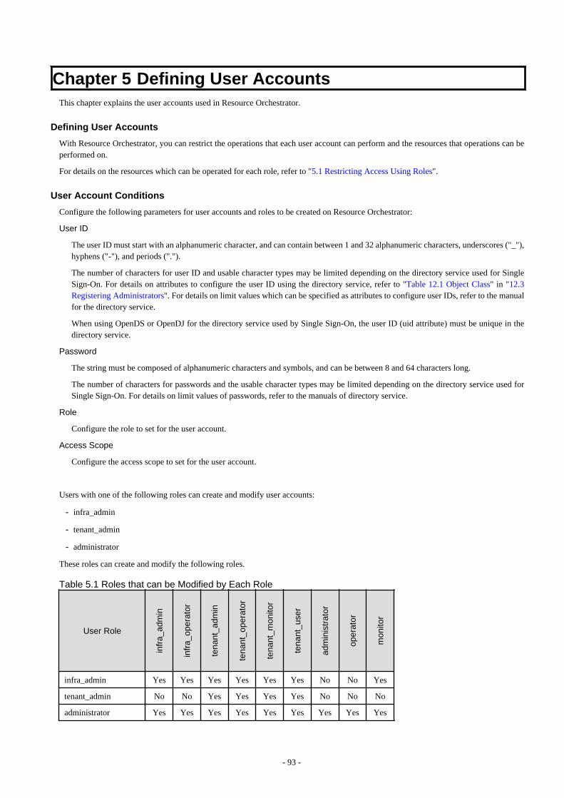
Chapter 5 Defining User AccountsThis chapter explains the user accounts used in Resource Orchestrator.
Defining User Accounts
With Resource Orchestrator, you can restrict the operations that each user account can perform and the resources that operations can beperformed on.
For details on the resources which can be operated for each role, refer to "5.1 Restricting Access Using Roles".
User Account Conditions
Configure the following parameters for user accounts and roles to be created on Resource Orchestrator:
User ID
The user ID must start with an alphanumeric character, and can contain between 1 and 32 alphanumeric characters, underscores ("_"),hyphens ("-"), and periods (".").
The number of characters for user ID and usable character types may be limited depending on the directory service used for SingleSign-On. For details on attributes to configure the user ID using the directory service, refer to "Table 12.1 Object Class" in "12.3Registering Administrators". For details on limit values which can be specified as attributes to configure user IDs, refer to the manualfor the directory service.
When using OpenDS or OpenDJ for the directory service used by Single Sign-On, the user ID (uid attribute) must be unique in thedirectory service.
Password
The string must be composed of alphanumeric characters and symbols, and can be between 8 and 64 characters long.
The number of characters for passwords and the usable character types may be limited depending on the directory service used forSingle Sign-On. For details on limit values of passwords, refer to the manuals of directory service.
Role
Configure the role to set for the user account.
Access Scope
Configure the access scope to set for the user account.
Users with one of the following roles can create and modify user accounts:
- infra_admin
- tenant_admin
- administrator
These roles can create and modify the following roles.
Table 5.1 Roles that can be Modified by Each Role
User Role
infr
a_ad
min
infr
a_op
erat
or
tena
nt_a
dmin
tena
nt_o
pera
tor
tena
nt_m
onito
r
tena
nt_u
ser
adm
inis
trat
or
oper
ator
mon
itor
infra_admin Yes Yes Yes Yes Yes Yes No No Yes
tenant_admin No No Yes Yes Yes Yes No No No
administrator Yes Yes Yes Yes Yes Yes Yes Yes Yes
- 93 -
5.1 Restricting Access Using RolesThis section explains the control of access using roles.
5.1.1 OverviewResource Orchestrator can limit the available operations and resources based on the user.
- Collections of possible operations
These are referred to as roles.
- Resources that can be operated
These are referred to as access scope.The access scope of a user who was assigned the tenant administrator role or the tenant user role is a tenant that they manage and use.
Privileges can be controlled by configuring the roles and access scope based on users.
Role
The following names are used for roles. For details on the detailed operation privileges for each role, refer to "Table 5.3 Operation Scopesof Roles" in "5.1.2 Roles and Available Operations".
Infrastructure Administrative Role
- Infrastructure administrator (infra_admin)
Infrastructure administrators manage the ICT resources (servers, storage, networks, and system images) in a private cloud.Using Resource Orchestrator, infrastructure administrators collectively manage ICT resources in resource pools, while monitoringthe load and performing addition, replacement, and maintenance of ICT resources when necessary.Infrastructure administrators prepare L-Platform templates of pre-defined logical platforms (L-Platforms) according to tenant useror tenant administrator needs, and publish them for use by tenant users or tenant administrators.In accordance with the application process, infrastructure administrators may also receive and review applications from tenantusers or tenant administrators.
The main roles and operations of infrastructure administrators are given below.
- Manage (add, switch, and maintain) the ICT resources (servers, storage, networks, and system images) in a private cloud
- Manage shared pools (global pools)
- Create and publish L-Platform templates
- Review logical platform (L-Platform) usage applications
- Infrastructure operator (infra_operator)
An infrastructure operator can only monitor an L-Platform. Power operations and backup for resources in a resource pool can alsobe executed by an infrastructure operator.
- Infrastructure monitor (monitor)
A monitor can only monitor all resources.
Tenant Management Roles
- Tenant administrator (tenant_admin)
Tenant administrators prepare an L-Platform template which is specific to the tenant pre-defined by the infrastructure administratoraccording to tenant user needs, and publish it for tenant users to use.In accordance with the application process, tenant administrators may also receive and approve applications from tenant users.Tenant administrators can check the usage status and monitor the operational statuses of tenant users.
The main roles and operations of tenant administrators are given below.
- Manage resource pools (local pools) dedicated to tenants
- Manage L-Platform templates
- 94 -
- Manage accounts of tenant users
- Review and approve logical platform (L-Platform) usage applications
- Tenant operator (tenant_operator)
Tenant operator can only perform the following operations from the operations which tenant administrators can perform.
- Resource backup
- L-Platform power operation
- Resource monitoring of all tenants
- Tenant and local pool monitoring
- Tenant monitor (tenant_monitor)
A tenant monitor can only monitor L-Platforms and L-Servers.
Tenant Use Roles
- Tenant user (tenant_user)
Tenant users can apply to use logical platforms (L-Platforms), and use logical platforms (L-Platforms) configured according totheir application.When the authorization of the tenant administration department manager is required for an application, tenant users must requestauthorization from the manager in accordance with the application process.
The main roles and operations of tenant users are given below.
- Apply for logical platform (L-Platform) usage
- Check resource usage conditions
- L-Platform User (lplatform_user)
L-Platform User is the role to enable tenant users (tenant_user) to use L-Platforms.L-Platform users can operate, change, and delete L-Platforms.This role is automatically assigned when an L-Platform is created. When the L-Platform is deleted, the assigned role is deletedautomatically. Addition and deletion is not necessary.
Multiple Roles
- Administrator (administrator)
An administrator is both an infrastructure administrator and a tenant administrator.
- Operator (operator)
An operator is both an infrastructure operator and a tenant operator.
- Monitor (monitor)
A monitor can only monitor all resources.
User Groups
User groups are the function for executing batch management of multiple users. By configuring roles and access scopes in the same wayas for users, user privileges for all users belonging to the user group can be configured as a batch operation.
If no user group is specified when creating a user, the user group will be the same as the user who performed creation. Therefore, it is notnecessary to consider the existence of user groups, when using a user within the same department.
When resource folders and resources specified in the access scope of a user and a user group are deleted, they are also deleted from theaccess scope and the role settings.
For details on the relations on access scope and role settings of a user and a user group, refer to "Table 5.2 Relations on Access Scope andRole Settings of Users and User Groups".
- 95 -

Table 5.2 Relations on Access Scope and Role Settings of Users and User GroupsUsers User Groups Access Scope and Roles
Configured Configured User configurations are valid
Configured Not configured User configurations are valid
Not configured Configured User group configurations are valid
Not configured Not configured All resources are inaccessible
For user groups, only "supervisor" and "monitor" are defined by default.
"supervisor" User Group
For the "supervisor" user group, the access scope and role of "all=administrator" are configured."all=administrator" is the role for administrators (administrators who are both infrastructure administrators and tenant administrators)with unlimited access scopes.
"monitor" User Group
For the "monitor" user group, the access scope and role of "all=monitor" are configured."all=monitor" is the role for monitors (monitors who are both infrastructure monitors and tenant monitors) with unlimited access scopes.
Tenant and User Group
When a tenant is created, the user group corresponding to a tenant will be created. When the tenant administrator and tenant users arecreated, they belong to a user group corresponding to the tenant.
5.1.2 Roles and Available OperationsThis section explains roles.
For details on how to configure roles and access scopes for users and user groups, refer to "Chapter 3 Configuring Users and CustomizingRoles" in the "User's Guide for Infrastructure Administrators (Resource Management) CE".
By specifying a combination of role and access scope for the target user or user group, the access privileges are restricted. The accessscope is restricted by specifying resource folders, resource pools, or resources in the orchestration tree.
Among the users with the infrastructure admin role, those users who have had their scope of access limited can only refer to certainresources. For this reason, only an orchestration tree can be used among the trees of a resource tab. Switchover to other trees is not possible.
For details on trees, refer to "A.1 ROR Console" in the "User's Guide for Infrastructure Administrators (Resource Management) CE".
Note
Specify "all" (no access scope restriction) for the access scope of the administrator role, operator role, monitor role, infrastructureadministrator role, and infrastructure operator role.
Table 5.3 Operation Scopes of Roles
Target Operation
infr
a_ad
min
infr
a_op
erat
or
tena
nt_a
dmin
tena
nt_o
pera
tor
tena
nt_m
onito
r
tena
nt_u
ser
adm
inis
trat
or
oper
ator
mon
itor
L-Platform
Subscribe No No Yes No No Yes Yes No No
Reconfiguration No No Yes No No Yes Yes No No
Movement Yes No No No No No Yes No No
Cancel No No Yes No No Yes Yes No No
- 96 -
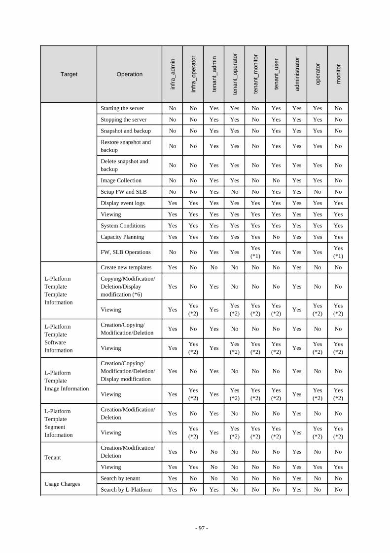
Target Operation
infr
a_ad
min
infr
a_op
erat
or
tena
nt_a
dmin
tena
nt_o
pera
tor
tena
nt_m
onito
r
tena
nt_u
ser
adm
inis
trat
or
oper
ator
mon
itor
Starting the server No No Yes Yes No Yes Yes Yes No
Stopping the server No No Yes Yes No Yes Yes Yes No
Snapshot and backup No No Yes Yes No Yes Yes Yes No
Restore snapshot andbackup
No No Yes Yes No Yes Yes Yes No
Delete snapshot andbackup
No No Yes Yes No Yes Yes Yes No
Image Collection No No Yes Yes No No Yes Yes No
Setup FW and SLB No No Yes No No Yes Yes No No
Display event logs Yes Yes Yes Yes Yes Yes Yes Yes Yes
Viewing Yes Yes Yes Yes Yes Yes Yes Yes Yes
System Conditions Yes Yes Yes Yes Yes Yes Yes Yes Yes
Capacity Planning Yes Yes Yes Yes Yes No Yes Yes Yes
FW, SLB Operations No No Yes YesYes(*1)
Yes Yes YesYes(*1)
L-PlatformTemplateTemplateInformation
Create new templates Yes No No No No No Yes No No
Copying/Modification/Deletion/Displaymodification (*6)
Yes No Yes No No No Yes No No
Viewing YesYes(*2)
YesYes(*2)
Yes(*2)
Yes(*2)
YesYes(*2)
Yes(*2)
L-PlatformTemplateSoftwareInformation
Creation/Copying/Modification/Deletion
Yes No Yes No No No Yes No No
Viewing YesYes(*2)
YesYes(*2)
Yes(*2)
Yes(*2)
YesYes(*2)
Yes(*2)
L-PlatformTemplateImage Information
Creation/Copying/Modification/Deletion/Display modification
Yes No Yes No No No Yes No No
Viewing YesYes(*2)
YesYes(*2)
Yes(*2)
Yes(*2)
YesYes(*2)
Yes(*2)
L-PlatformTemplateSegmentInformation
Creation/Modification/Deletion
Yes No Yes No No No Yes No No
Viewing YesYes(*2)
YesYes(*2)
Yes(*2)
Yes(*2)
YesYes(*2)
Yes(*2)
Tenant
Creation/Modification/Deletion
Yes No No No No No Yes No No
Viewing Yes Yes No No No No Yes Yes Yes
Usage ChargesSearch by tenant Yes No No No No No Yes No No
Search by L-Platform Yes No Yes No No No Yes No No
- 97 -
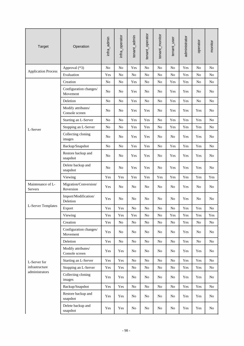
Target Operation
infr
a_ad
min
infr
a_op
erat
or
tena
nt_a
dmin
tena
nt_o
pera
tor
tena
nt_m
onito
r
tena
nt_u
ser
adm
inis
trat
or
oper
ator
mon
itor
Application ProcessApproval (*3) No No Yes No No No Yes No No
Evaluation Yes No No No No No Yes No No
L-Server
Creation No No Yes No No Yes Yes No No
Configuration changes/Movement
No No Yes No No Yes Yes No No
Deletion No No Yes No No Yes Yes No No
Modify attributes/Console screen
No No Yes Yes No Yes Yes Yes No
Starting an L-Server No No Yes Yes No Yes Yes Yes No
Stopping an L-Server No No Yes Yes No Yes Yes Yes No
Collecting cloningimages
No No Yes Yes No No Yes Yes No
Backup/Snapshot No No Yes Yes No Yes Yes Yes No
Restore backup andsnapshot
No No Yes Yes No Yes Yes Yes No
Delete backup andsnapshot
No No Yes Yes No Yes Yes Yes No
Viewing Yes Yes Yes Yes Yes Yes Yes Yes Yes
Maintenance of L-Servers
Migration/Conversion/Reversion
Yes No No No No No Yes No No
L-Server Templates
Import/Modification/Deletion
Yes No No No No No Yes No No
Export Yes Yes No No No No Yes Yes No
Viewing Yes Yes Yes No No Yes Yes Yes Yes
L-Server forinfrastructureadministrators
Creation Yes No No No No No Yes No No
Configuration changes/Movement
Yes No No No No No Yes No No
Deletion Yes No No No No No Yes No No
Modify attributes/Console screen
Yes Yes No No No No Yes Yes No
Starting an L-Server Yes Yes No No No No Yes Yes No
Stopping an L-Server Yes Yes No No No No Yes Yes No
Collecting cloningimages
Yes Yes No No No No Yes Yes No
Backup/Snapshot Yes Yes No No No No Yes Yes No
Restore backup andsnapshot
Yes Yes No No No No Yes Yes No
Delete backup andsnapshot
Yes Yes No No No No Yes Yes No
- 98 -
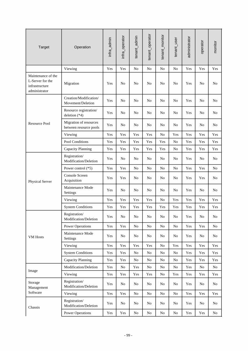
Target Operation
infr
a_ad
min
infr
a_op
erat
or
tena
nt_a
dmin
tena
nt_o
pera
tor
tena
nt_m
onito
r
tena
nt_u
ser
adm
inis
trat
or
oper
ator
mon
itor
Viewing Yes Yes No No No No Yes Yes Yes
Maintenance of theL-Server for theinfrastructureadministrator
Migration Yes No No No No No Yes No No
Resource Pool
Creation/Modification/Movement/Deletion
Yes No No No No No Yes No No
Resource registration/deletion (*4)
Yes No No No No No Yes No No
Migration of resourcesbetween resource pools
Yes No No No No No Yes No No
Viewing Yes Yes Yes Yes No Yes Yes Yes Yes
Pool Conditions Yes Yes Yes Yes Yes No Yes Yes Yes
Capacity Planning Yes Yes Yes Yes Yes No Yes Yes Yes
Physical Server
Registration/Modification/Deletion
Yes No No No No No Yes No No
Power control (*5) Yes Yes No No No No Yes Yes No
Console ScreenAcquisition
Yes Yes No No No No Yes Yes No
Maintenance ModeSettings
Yes No No No No No Yes No No
Viewing Yes Yes Yes Yes No Yes Yes Yes Yes
System Conditions Yes Yes Yes Yes Yes Yes Yes Yes Yes
VM Hosts
Registration/Modification/Deletion
Yes No No No No No Yes No No
Power Operations Yes Yes No No No No Yes Yes No
Maintenance ModeSettings
Yes No No No No No Yes No No
Viewing Yes Yes Yes Yes No Yes Yes Yes Yes
System Conditions Yes Yes No No No No Yes Yes Yes
Capacity Planning Yes Yes No No No No Yes Yes Yes
ImageModification/Deletion Yes No Yes No No No Yes No No
Viewing Yes Yes Yes Yes No Yes Yes Yes Yes
StorageManagementSoftware
Registration/Modification/Deletion
Yes No No No No No Yes No No
Viewing Yes Yes No No No No Yes Yes Yes
Chassis
Registration/Modification/Deletion
Yes No No No No No Yes No No
Power Operations Yes Yes No No No No Yes Yes No
- 99 -

Target Operation
infr
a_ad
min
infr
a_op
erat
or
tena
nt_a
dmin
tena
nt_o
pera
tor
tena
nt_m
onito
r
tena
nt_u
ser
adm
inis
trat
or
oper
ator
mon
itor
Viewing Yes Yes No No No No Yes Yes Yes
Network
Creation/Modification/Deletion
Yes No No No No No Yes No No
Viewing Yes Yes No No No No Yes Yes Yes
Network Devices
Registration/Modification/Deletion
Yes No No No No No Yes No No
Viewing Yes Yes Yes Yes No Yes Yes Yes Yes
Management of DeviceConfiguration Files
Yes No No No No No Yes No No
Server NICDefinitions
Reflect/Display Yes No No No No No Yes No No
NetworkConfigurationInformation
Import/Export Yes No No No No No Yes No No
External servers Viewing Yes No No No No No Yes No No
Disk/Address/PowerMonitoring Device
Registration/Modification/Deletion(*4)
Yes No No No No No Yes No No
Viewing Yes Yes No No No No Yes Yes Yes
Pre-configurationImport/Export/Download templates
Yes No No No No No Yes No No
Resource Folders
Creation/Modification/Movement/Deletion
Yes No No No No No Yes No No
Viewing Yes Yes No No No No Yes Yes Yes
Users
Modification ofindividual information
Yes Yes Yes Yes Yes Yes Yes Yes Yes
Addition/Modification/Deletion of users in theuser group the userbelongs to
Yes No Yes No No No Yes No No
Addition/Modification/Deletion of users in otheruser groups
Yes No No No No No Yes No No
Viewing Yes Yes Yes Yes Yes Yes Yes Yes Yes
User Groups
Creation/Modification/Deletion
Yes No No No No No Yes No No
Viewing Yes Yes No No No No Yes Yes Yes
Yes: Can operateNo: Cannot operate
FW: FirewallSLB: Server load balancer
- 100 -
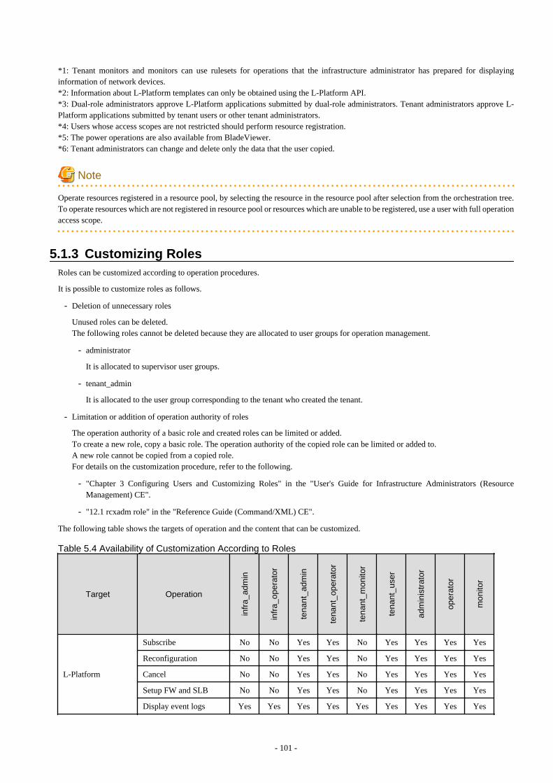
*1: Tenant monitors and monitors can use rulesets for operations that the infrastructure administrator has prepared for displayinginformation of network devices.*2: Information about L-Platform templates can only be obtained using the L-Platform API.*3: Dual-role administrators approve L-Platform applications submitted by dual-role administrators. Tenant administrators approve L-Platform applications submitted by tenant users or other tenant administrators.*4: Users whose access scopes are not restricted should perform resource registration.*5: The power operations are also available from BladeViewer.*6: Tenant administrators can change and delete only the data that the user copied.
Note
Operate resources registered in a resource pool, by selecting the resource in the resource pool after selection from the orchestration tree.To operate resources which are not registered in resource pool or resources which are unable to be registered, use a user with full operationaccess scope.
5.1.3 Customizing RolesRoles can be customized according to operation procedures.
It is possible to customize roles as follows.
- Deletion of unnecessary roles
Unused roles can be deleted.The following roles cannot be deleted because they are allocated to user groups for operation management.
- administrator
It is allocated to supervisor user groups.
- tenant_admin
It is allocated to the user group corresponding to the tenant who created the tenant.
- Limitation or addition of operation authority of roles
The operation authority of a basic role and created roles can be limited or added.To create a new role, copy a basic role. The operation authority of the copied role can be limited or added to.A new role cannot be copied from a copied role.For details on the customization procedure, refer to the following.
- "Chapter 3 Configuring Users and Customizing Roles" in the "User's Guide for Infrastructure Administrators (ResourceManagement) CE".
- "12.1 rcxadm role" in the "Reference Guide (Command/XML) CE".
The following table shows the targets of operation and the content that can be customized.
Table 5.4 Availability of Customization According to Roles
Target Operation
infr
a_ad
min
infr
a_op
erat
or
tena
nt_a
dmin
tena
nt_o
pera
tor
tena
nt_m
onito
r
tena
nt_u
ser
adm
inis
trat
or
oper
ator
mon
itor
L-Platform
Subscribe No No Yes Yes No Yes Yes Yes Yes
Reconfiguration No No Yes Yes No Yes Yes Yes Yes
Cancel No No Yes Yes No Yes Yes Yes Yes
Setup FW and SLB No No Yes Yes No Yes Yes Yes Yes
Display event logs Yes Yes Yes Yes Yes Yes Yes Yes Yes
- 101 -
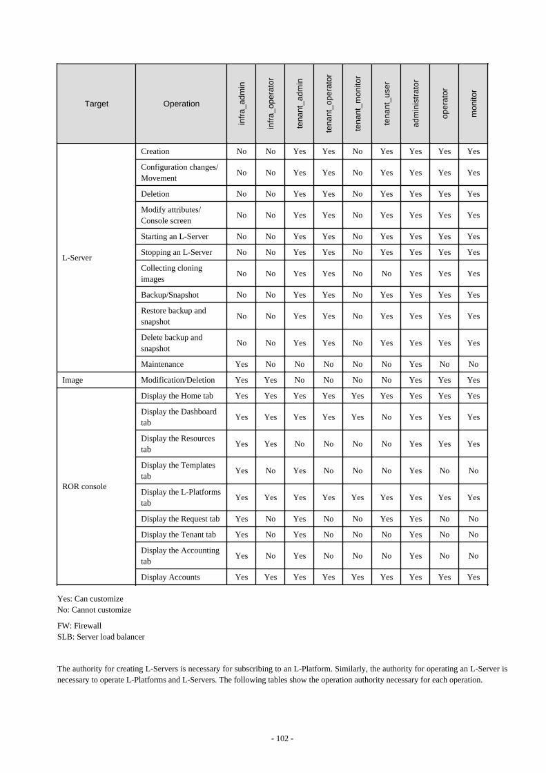
Target Operation
infr
a_ad
min
infr
a_op
erat
or
tena
nt_a
dmin
tena
nt_o
pera
tor
tena
nt_m
onito
r
tena
nt_u
ser
adm
inis
trat
or
oper
ator
mon
itor
L-Server
Creation No No Yes Yes No Yes Yes Yes Yes
Configuration changes/Movement
No No Yes Yes No Yes Yes Yes Yes
Deletion No No Yes Yes No Yes Yes Yes Yes
Modify attributes/Console screen
No No Yes Yes No Yes Yes Yes Yes
Starting an L-Server No No Yes Yes No Yes Yes Yes Yes
Stopping an L-Server No No Yes Yes No Yes Yes Yes Yes
Collecting cloningimages
No No Yes Yes No No Yes Yes Yes
Backup/Snapshot No No Yes Yes No Yes Yes Yes Yes
Restore backup andsnapshot
No No Yes Yes No Yes Yes Yes Yes
Delete backup andsnapshot
No No Yes Yes No Yes Yes Yes Yes
Maintenance Yes No No No No No Yes No No
Image Modification/Deletion Yes Yes No No No No Yes Yes Yes
ROR console
Display the Home tab Yes Yes Yes Yes Yes Yes Yes Yes Yes
Display the Dashboardtab
Yes Yes Yes Yes Yes No Yes Yes Yes
Display the Resourcestab
Yes Yes No No No No Yes Yes Yes
Display the Templatestab
Yes No Yes No No No Yes No No
Display the L-Platformstab
Yes Yes Yes Yes Yes Yes Yes Yes Yes
Display the Request tab Yes No Yes No No Yes Yes No No
Display the Tenant tab Yes No Yes No No No Yes No No
Display the Accountingtab
Yes No Yes No No No Yes No No
Display Accounts Yes Yes Yes Yes Yes Yes Yes Yes Yes
Yes: Can customizeNo: Cannot customize
FW: FirewallSLB: Server load balancer
The authority for creating L-Servers is necessary for subscribing to an L-Platform. Similarly, the authority for operating an L-Server isnecessary to operate L-Platforms and L-Servers. The following tables show the operation authority necessary for each operation.
- 102 -
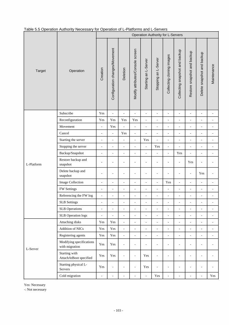
Table 5.5 Operation Authority Necessary for Operation of L-Platforms and L-Servers
Target Operation
Operation Authority for L-Servers
Cre
atio
n
Con
figur
atio
n ch
ange
s/M
ovem
ent
Del
etio
n
Mod
ify a
ttrib
utes
/Con
sole
scr
een
Sta
rtin
g an
L-S
erve
r
Sto
ppin
g an
L-S
erve
r
Col
lect
ing
clon
ing
imag
es
Col
lect
ing
snap
shot
and
bac
kup
Res
tore
sna
psho
t and
bac
kup
Del
ete
snap
shot
and
bac
kup
Mai
nten
ance
L-Platform
Subscribe Yes - - - - - - - - - -
Reconfiguration Yes Yes Yes Yes - - - - - - -
Movement - Yes - - - - - - - - -
Cancel - - Yes - - - - - - - -
Starting the server - - - - Yes - - - - - -
Stopping the server - - - - - Yes - - - - -
Backup/Snapshot - - - - - - - Yes - - -
Restore backup andsnapshot
- - - - - - - - Yes - -
Delete backup andsnapshot
- - - - - - - - - Yes -
Image Collection - - - - - - Yes - - - -
FW Settings - - - - - - - - - - -
Referencing the FW log - - - - - - - - - - -
SLB Settings - - - - - - - - - - -
SLB Operations - - - - - - - - - - -
SLB Operation logs - - - - - - - - - - -
L-Server
Attaching disks Yes Yes - - - - - - - - -
Addition of NICs Yes Yes - - - - - - - - -
Registering agents Yes Yes - - - - - - - - -
Modifying specificationswith migration
Yes Yes - - - - - - - - -
Starting withAttachAtBoot specified
Yes Yes - - Yes - - - - - -
Starting physical L-Servers
Yes - - - Yes - - - - - -
Cold migration - - - - - Yes - - - - Yes
Yes: Necessary-: Not necessary
- 103 -

FW: FirewallSLB: Server load balancer
- 104 -
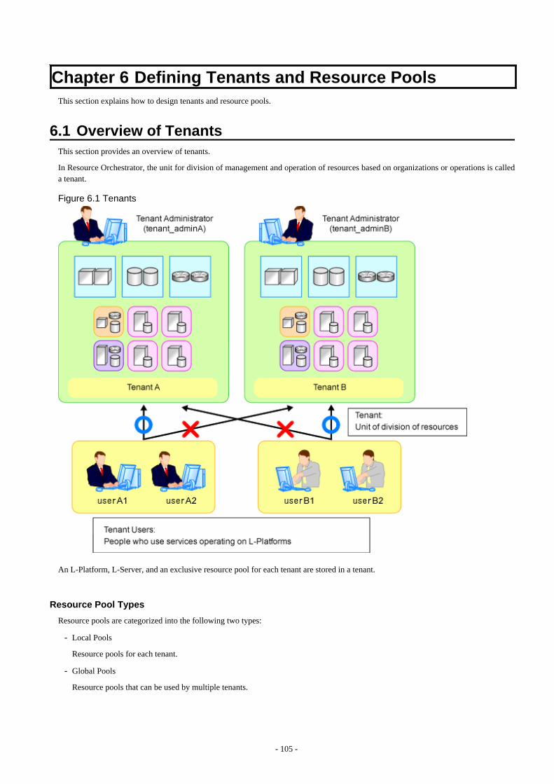
Chapter 6 Defining Tenants and Resource PoolsThis section explains how to design tenants and resource pools.
6.1 Overview of TenantsThis section provides an overview of tenants.
In Resource Orchestrator, the unit for division of management and operation of resources based on organizations or operations is calleda tenant.
Figure 6.1 Tenants
An L-Platform, L-Server, and an exclusive resource pool for each tenant are stored in a tenant.
Resource Pool Types
Resource pools are categorized into the following two types:
- Local Pools
Resource pools for each tenant.
- Global Pools
Resource pools that can be used by multiple tenants.
- 105 -
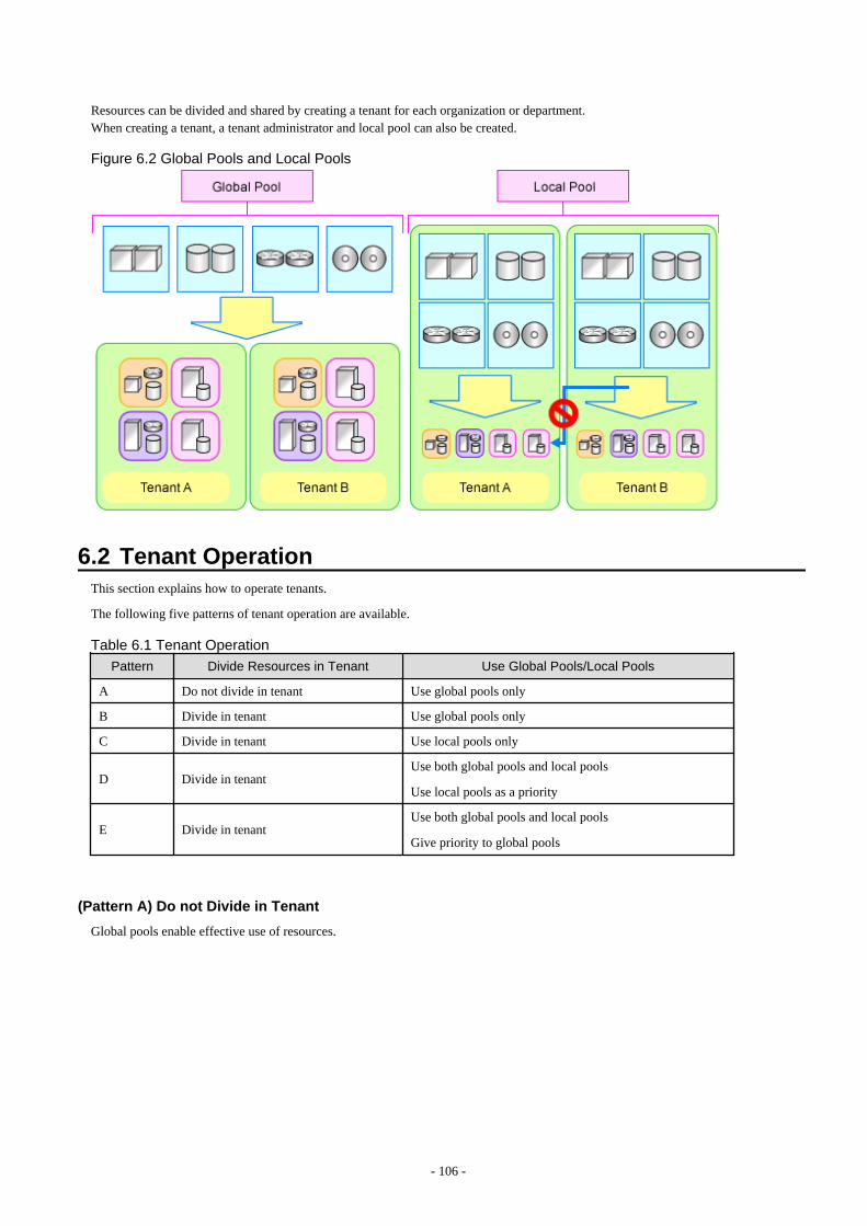
Resources can be divided and shared by creating a tenant for each organization or department.When creating a tenant, a tenant administrator and local pool can also be created.
Figure 6.2 Global Pools and Local Pools
6.2 Tenant OperationThis section explains how to operate tenants.
The following five patterns of tenant operation are available.
Table 6.1 Tenant Operation
Pattern Divide Resources in Tenant Use Global Pools/Local Pools
A Do not divide in tenant Use global pools only
B Divide in tenant Use global pools only
C Divide in tenant Use local pools only
D Divide in tenantUse both global pools and local pools
Use local pools as a priority
E Divide in tenantUse both global pools and local pools
Give priority to global pools
(Pattern A) Do not Divide in Tenant
Global pools enable effective use of resources.
- 106 -
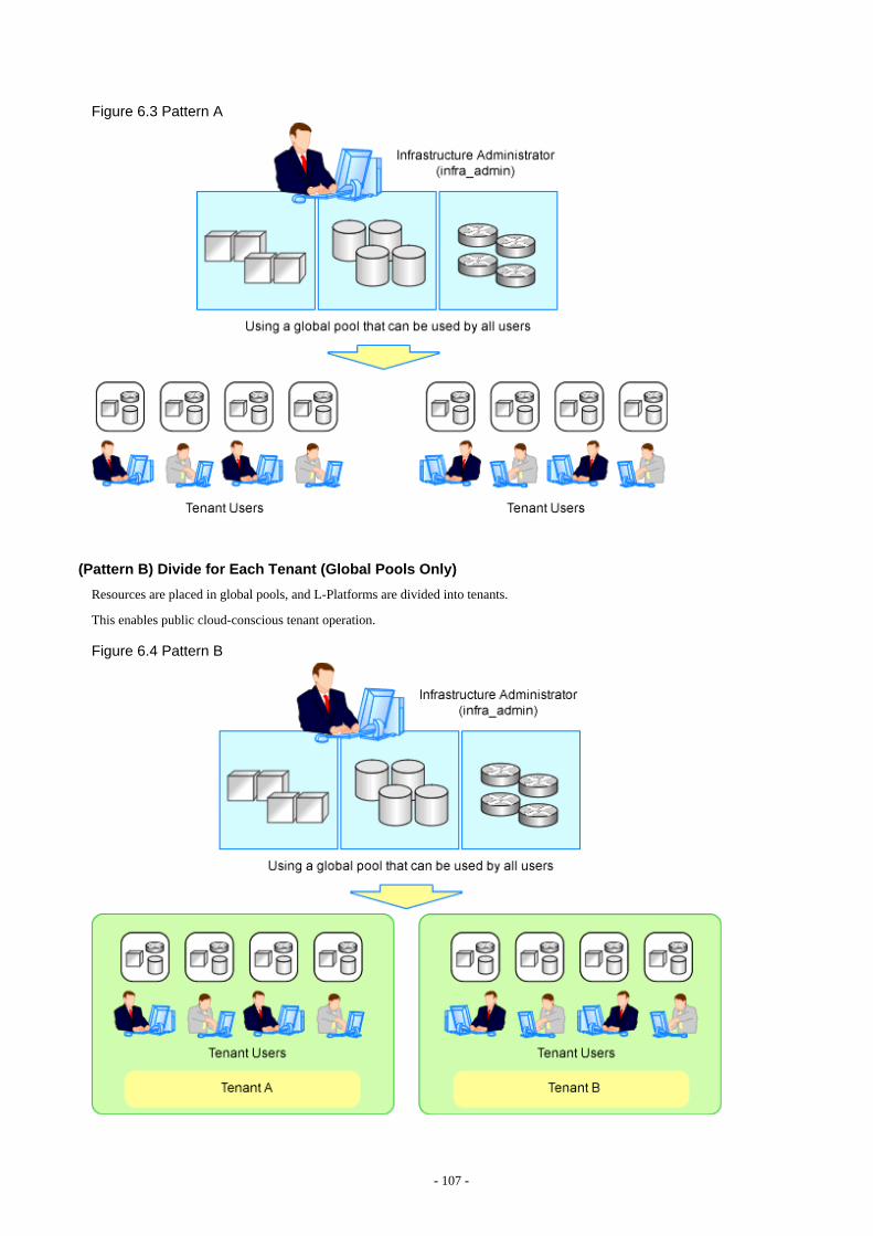
Figure 6.3 Pattern A
(Pattern B) Divide for Each Tenant (Global Pools Only)
Resources are placed in global pools, and L-Platforms are divided into tenants.
This enables public cloud-conscious tenant operation.
Figure 6.4 Pattern B
- 107 -
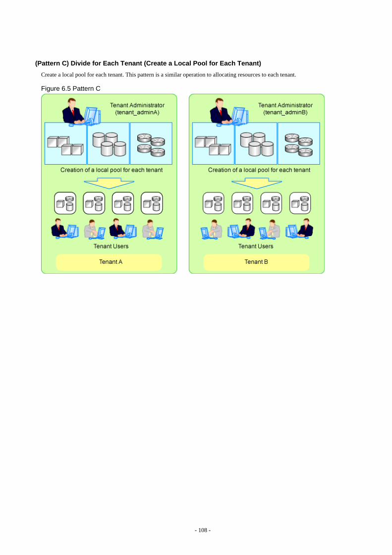
(Pattern C) Divide for Each Tenant (Create a Local Pool for Each Tenant)
Create a local pool for each tenant. This pattern is a similar operation to allocating resources to each tenant.
Figure 6.5 Pattern C
- 108 -
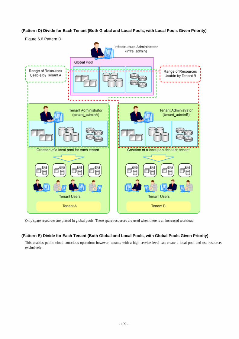
(Pattern D) Divide for Each Tenant (Both Global and Local Pools, with Local Pools Given Priority)
Figure 6.6 Pattern D
Only spare resources are placed in global pools. These spare resources are used when there is an increased workload.
(Pattern E) Divide for Each Tenant (Both Global and Local Pools, with Global Pools Given Priority)
This enables public cloud-conscious operation; however, tenants with a high service level can create a local pool and use resourcesexclusively.
- 109 -
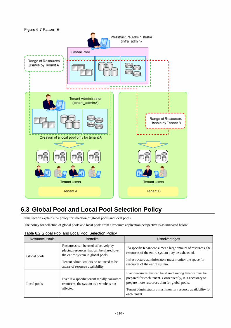
Figure 6.7 Pattern E
6.3 Global Pool and Local Pool Selection PolicyThis section explains the policy for selection of global pools and local pools.
The policy for selection of global pools and local pools from a resource application perspective is as indicated below.
Table 6.2 Global Pool and Local Pool Selection Policy
Resource Pools Benefits Disadvantages
Global pools
Resources can be used effectively byplacing resources that can be shared overthe entire system in global pools.
Tenant administrators do not need to beaware of resource availability.
If a specific tenant consumes a large amount of resources, theresources of the entire system may be exhausted.
Infrastructure administrators must monitor the space forresources of the entire system.
Local poolsEven if a specific tenant rapidly consumesresources, the system as a whole is notaffected.
Even resources that can be shared among tenants must beprepared for each tenant. Consequently, it is necessary toprepare more resources than for global pools.
Tenant administrators must monitor resource availability foreach tenant.
- 110 -
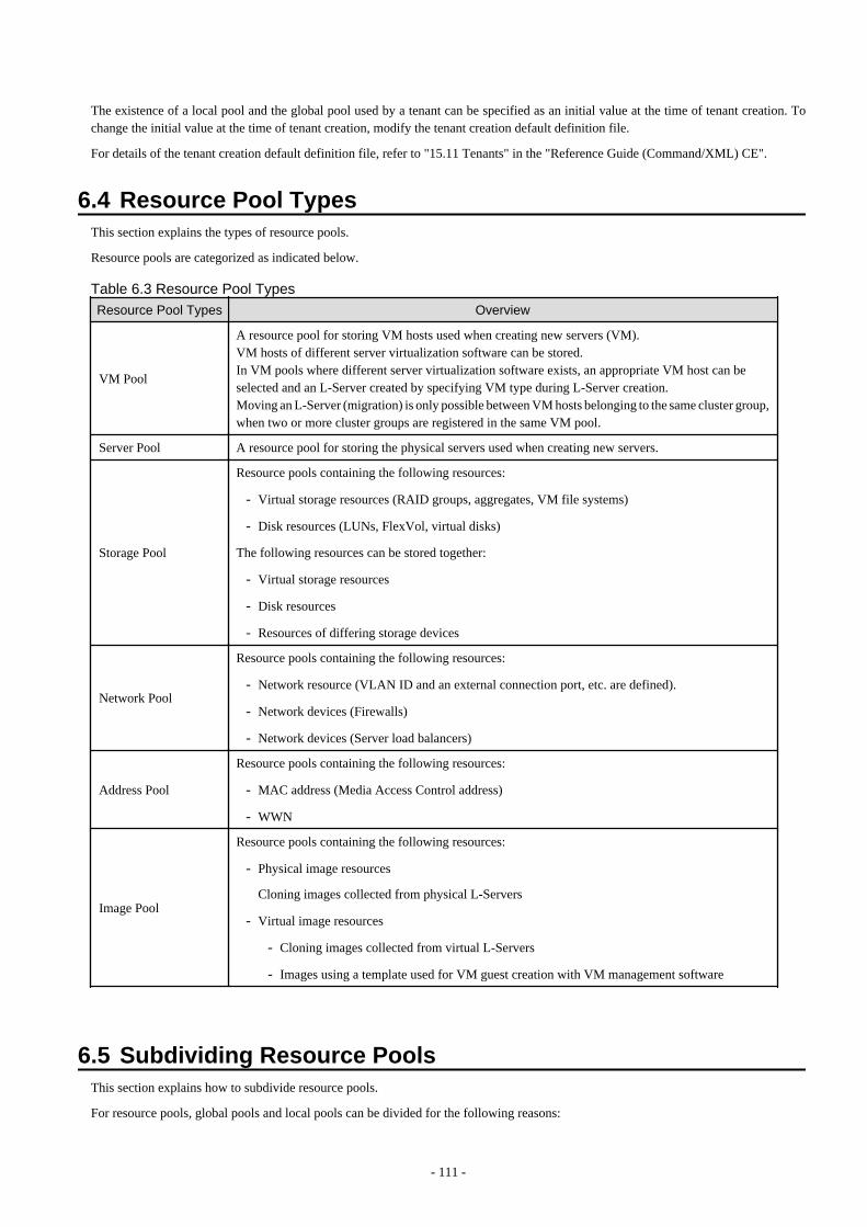
The existence of a local pool and the global pool used by a tenant can be specified as an initial value at the time of tenant creation. Tochange the initial value at the time of tenant creation, modify the tenant creation default definition file.
For details of the tenant creation default definition file, refer to "15.11 Tenants" in the "Reference Guide (Command/XML) CE".
6.4 Resource Pool TypesThis section explains the types of resource pools.
Resource pools are categorized as indicated below.
Table 6.3 Resource Pool TypesResource Pool Types Overview
VM Pool
A resource pool for storing VM hosts used when creating new servers (VM).VM hosts of different server virtualization software can be stored.In VM pools where different server virtualization software exists, an appropriate VM host can beselected and an L-Server created by specifying VM type during L-Server creation.Moving an L-Server (migration) is only possible between VM hosts belonging to the same cluster group,when two or more cluster groups are registered in the same VM pool.
Server Pool A resource pool for storing the physical servers used when creating new servers.
Storage Pool
Resource pools containing the following resources:
- Virtual storage resources (RAID groups, aggregates, VM file systems)
- Disk resources (LUNs, FlexVol, virtual disks)
The following resources can be stored together:
- Virtual storage resources
- Disk resources
- Resources of differing storage devices
Network Pool
Resource pools containing the following resources:
- Network resource (VLAN ID and an external connection port, etc. are defined).
- Network devices (Firewalls)
- Network devices (Server load balancers)
Address Pool
Resource pools containing the following resources:
- MAC address (Media Access Control address)
- WWN
Image Pool
Resource pools containing the following resources:
- Physical image resources
Cloning images collected from physical L-Servers
- Virtual image resources
- Cloning images collected from virtual L-Servers
- Images using a template used for VM guest creation with VM management software
6.5 Subdividing Resource PoolsThis section explains how to subdivide resource pools.
For resource pools, global pools and local pools can be divided for the following reasons:
- 111 -

- Resource differences (VM type, storage type, OS type, etc.)
- Performance differences
- Application differences (divide by user, etc.)
It is recommended to name resource pools including divided resources using names that make it clear to resource pool users.
6.6 Concept for Separating Tenants by Resource PoolThis section explains the concept for separating tenants (necessity of local pool creation) for each resource pool.
6.6.1 Server PoolThis section explains the concept for separating tenants of server pools.
Servers of differing models can be placed in the same server pool.When performing server redundancy, consider a server pool to use as the work servers and spare server pool to use as backup servers.
- Use the same pool for servers and spare servers
As well as the work server, a spare server must also be considered.
- Separate the server pool and spare server pool
The server pool can be placed in a local pool, and the spare server pool can be placed in a global pool.
6.6.2 VM PoolThis section explains the concept for separating tenants of VM pools.
VM hosts of different server virtualization software can be stored in VM pools.Even if a VM host exists in one VM pool, virtual L-Servers can be placed in a different tenant. Therefore, it is not necessary to separateVM pools.
However, local VM pools must be created for each tenant in the following cases:
- Consolidate VM hosts comprising VMwareDRS or HA in VM pools under the same tenant. A virtual machine may operate beyondtenants by VM management software control, when VM hosts are registered in different tenants.
- Place VM pools separately for each tenant when considering the vulnerabilities and loads of VM hosts.
- This section explains the concept for separating tenants (necessity of local pool creation) for each resource pool.
- When using VM hosts in tenants linked with a virtual fabric (VFAB) other than the default VFAB in Converged Fabric, create separateVM pools for each tenant.
6.6.3 Storage PoolThis section explains the concept for separating tenants of storage pools.
Virtual storage resources or disk resources of differing server virtualization software can be placed in the same storage pool.Disk resources generated from virtual storage resources and disk resources created in advance can also be stored together.
In the following cases, place storage pools separately.
- When separating storage pools according to usage
- When maintaining unique user information for security reasons
- When giving consideration to performance
- When using them as shared disks (from the disk resources created in advance)
- 112 -
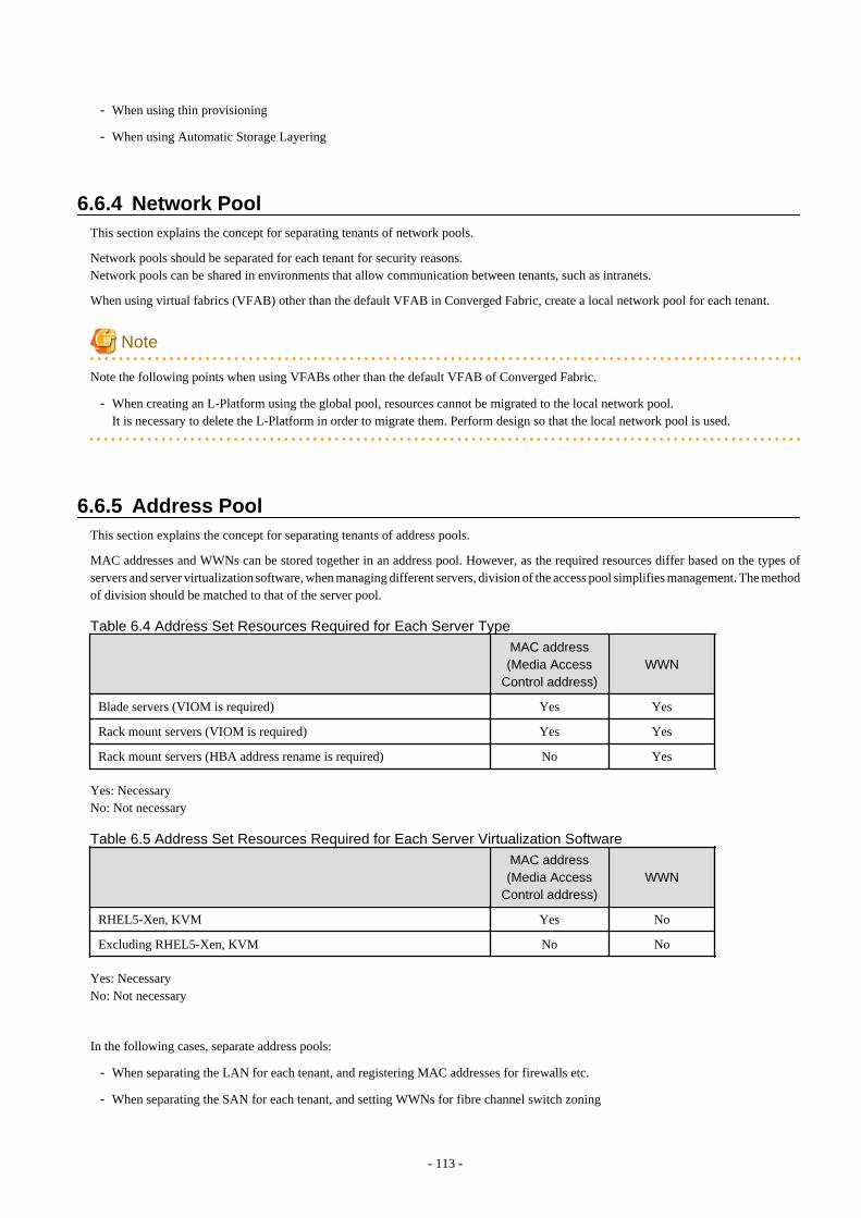
- When using thin provisioning
- When using Automatic Storage Layering
6.6.4 Network PoolThis section explains the concept for separating tenants of network pools.
Network pools should be separated for each tenant for security reasons.Network pools can be shared in environments that allow communication between tenants, such as intranets.
When using virtual fabrics (VFAB) other than the default VFAB in Converged Fabric, create a local network pool for each tenant.
Note
Note the following points when using VFABs other than the default VFAB of Converged Fabric.
- When creating an L-Platform using the global pool, resources cannot be migrated to the local network pool.It is necessary to delete the L-Platform in order to migrate them. Perform design so that the local network pool is used.
6.6.5 Address PoolThis section explains the concept for separating tenants of address pools.
MAC addresses and WWNs can be stored together in an address pool. However, as the required resources differ based on the types ofservers and server virtualization software, when managing different servers, division of the access pool simplifies management. The methodof division should be matched to that of the server pool.
Table 6.4 Address Set Resources Required for Each Server Type
MAC address(Media Access
Control address)WWN
Blade servers (VIOM is required) Yes Yes
Rack mount servers (VIOM is required) Yes Yes
Rack mount servers (HBA address rename is required) No Yes
Yes: NecessaryNo: Not necessary
Table 6.5 Address Set Resources Required for Each Server Virtualization Software
MAC address(Media Access
Control address)WWN
RHEL5-Xen, KVM Yes No
Excluding RHEL5-Xen, KVM No No
Yes: NecessaryNo: Not necessary
In the following cases, separate address pools:
- When separating the LAN for each tenant, and registering MAC addresses for firewalls etc.
- When separating the SAN for each tenant, and setting WWNs for fibre channel switch zoning
- 113 -

- When using software that is aware of MAC addresses for license authentication etc.
Note
When multiple address sets are created, design the ranges of addresses so that they do not overlap between the address sets.
When a range of addresses overlaps on the same LAN or SAN network, it may become impossible to communicate correctly, and datamay be damaged by same volume access.
When creation of address sets in which overlapping of the range of the MAC addresses is unavoidable, ensure that the following systemdesign is performed, and no MAC address is duplicated on same LAN network.
- Separate the network segments (VLAN)
- Configure an excluded range of MAC addresses so that a duplicated MAC address is not assigned
6.6.6 Image PoolThis section explains the concept for separating tenants of image pools.
For images of tenant-independent operating systems, it is not necessary to separate image pools.
It is necessary to separate image pools for each tenant for images that have tenant-unique information.Images gathered after configuration of tenant-specific applications should be managed in the local pool of the relevant tenant.
- 114 -
Chapter 7 Defining High Availability and Disaster RecoveryHigh availability systems can be provided smoothly using the following functions of Resource Orchestrator.
- L-Server redundancy
L-Server redundancy is possible with Resource Orchestrator.
On physical L-Servers, by specifying a spare server pool, an operating server can be switched to a spare server when server failureoccurs.On virtual L-Servers, settings differ according to the server virtualization software being used.For details, refer to "18.1.1 High Availability of L-Servers" in the "Operation Guide CE".
- Server switchover when a chassis fails
If a blade chassis in a configuration where Resource Orchestrator manages multiple blade chassis fails, when starting the physical L-Server on a blade chassis that is not damaged, operations can be re-started.For details, refer to "18.1.2 Blade Chassis High Availability" in the "Operation Guide CE".
When creating VM hosts on physical L-Servers, server switchover can be performed for VM hosts if chassis failure occurs.For details, refer to "Appendix D Installing VM Hosts on Physical L-Servers" in the "Setup Guide CE".
- Switchover of operating or standby status of storage
For physical L-Servers, realizes the switchover of operating or standby disks (system/data disks) in configurations in which replicationof the operating storage volume used by an L-Server to a standby storage volume is configured.For details on prerequisites, refer to "7.2 Storage Chassis High Availability Design".
For details on operation methods, refer to "18.1.3 High Availability for Storage Chassis" in the "Operation Guide CE".
In the case of VM hosts, failover of disks from the primary site to the backup site can also be performed by building VM hosts onphysical L-Servers.
For details, refer to "Appendix D Installing VM Hosts on Physical L-Servers" in the "Setup Guide CE".
- Admin server redundancy
Managers can be operated in cluster systems with Resource Orchestrator.
When operating the admin server in a Windows or Linux environment, redundancy for managers is also possible using clusteringsoftware.
An admin server can be operated on VMware and Hyper-V virtual machines.
Using redundancy for virtual machines, redundancy for managers is also possible.For details on operation methods, refer to "18.2 High Availability for Admin Servers" in the "Operation Guide CE".
- Disaster Recovery
Disaster recovery can be done in a simple and reliable way by exporting and importing the following information between managersof Resource Orchestrator.
- L-Platform Template
- L-Platform Configuration Information
- Resource Information
- Accounting Information
- Metering Log
For details on prerequisites, refer to "Chapter 2 Design" in the "DR Option Instruction".
For details on installing and operating Disaster Recovery, refer to "Chapter 3 Installation" and "Chapter 4 Operation" in the "DROption Instruction".
7.1 Blade Chassis High Availability DesignTo perform server switchover for chassis failures, it is necessary to set the server switchover settings in advance.
- 115 -
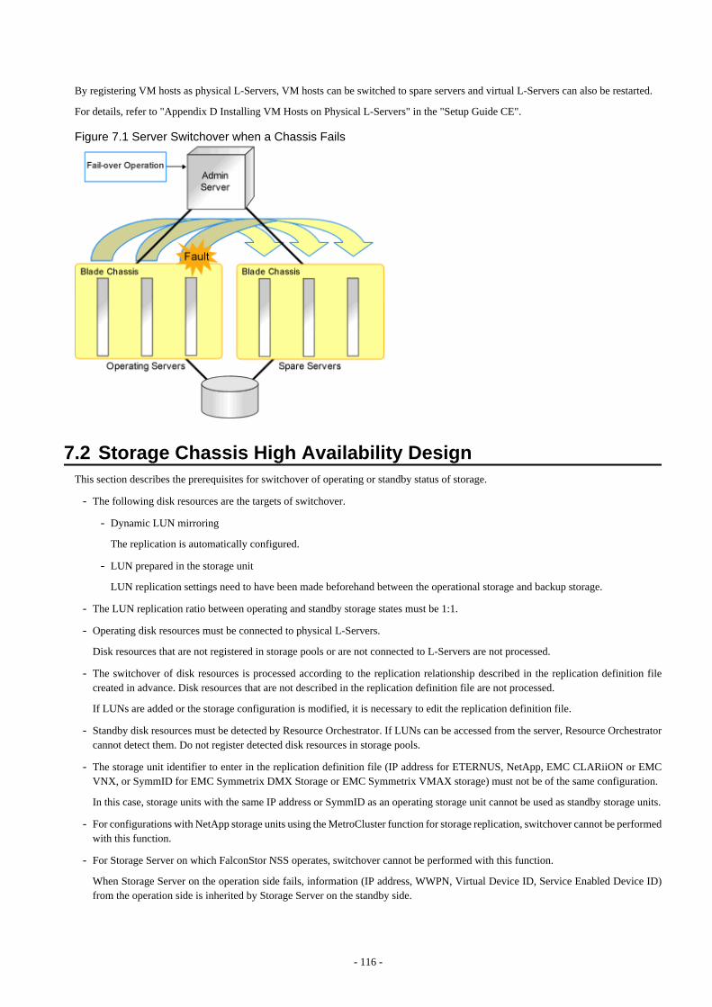
By registering VM hosts as physical L-Servers, VM hosts can be switched to spare servers and virtual L-Servers can also be restarted.
For details, refer to "Appendix D Installing VM Hosts on Physical L-Servers" in the "Setup Guide CE".
Figure 7.1 Server Switchover when a Chassis Fails
7.2 Storage Chassis High Availability DesignThis section describes the prerequisites for switchover of operating or standby status of storage.
- The following disk resources are the targets of switchover.
- Dynamic LUN mirroring
The replication is automatically configured.
- LUN prepared in the storage unit
LUN replication settings need to have been made beforehand between the operational storage and backup storage.
- The LUN replication ratio between operating and standby storage states must be 1:1.
- Operating disk resources must be connected to physical L-Servers.
Disk resources that are not registered in storage pools or are not connected to L-Servers are not processed.
- The switchover of disk resources is processed according to the replication relationship described in the replication definition filecreated in advance. Disk resources that are not described in the replication definition file are not processed.
If LUNs are added or the storage configuration is modified, it is necessary to edit the replication definition file.
- Standby disk resources must be detected by Resource Orchestrator. If LUNs can be accessed from the server, Resource Orchestratorcannot detect them. Do not register detected disk resources in storage pools.
- The storage unit identifier to enter in the replication definition file (IP address for ETERNUS, NetApp, EMC CLARiiON or EMCVNX, or SymmID for EMC Symmetrix DMX Storage or EMC Symmetrix VMAX storage) must not be of the same configuration.
In this case, storage units with the same IP address or SymmID as an operating storage unit cannot be used as standby storage units.
- For configurations with NetApp storage units using the MetroCluster function for storage replication, switchover cannot be performedwith this function.
- For Storage Server on which FalconStor NSS operates, switchover cannot be performed with this function.
When Storage Server on the operation side fails, information (IP address, WWPN, Virtual Device ID, Service Enabled Device ID)from the operation side is inherited by Storage Server on the standby side.
- 116 -
- To access operating and standby storage units from servers with physical L-Servers running on them, it is necessary to set the fibrechannel switch in advance.
If the storage unit is ETERNUS, no settings are required in advance.
- The time required for switchover is relative to the number of L-Servers using operating storage units and the number of disk resourcesbeing used by L-Servers.
It is recommended that a test be performed in advance to confirm the time for restoration from storage unit failure.
7.3 Admin Server High Availability DesignRedundancy for managers is possible with Resource Orchestrator.
High availability configuration of admin servers can be performed as follows.
Manager High Availability in Windows Guest Environments in Hyper-V environments
Design the admin server so it is in the configuration given below.
- Install the manager on a windows guest OS in a Hyper-V environment configured as a cluster using MSFC.
- Install the following software on the same VM guest as the manager.
- ServerView Operations Manager
- ServerView Virtual-IO Manager
- VM management software
- Storage management software (Other than Solutions Enabler)
- 117 -
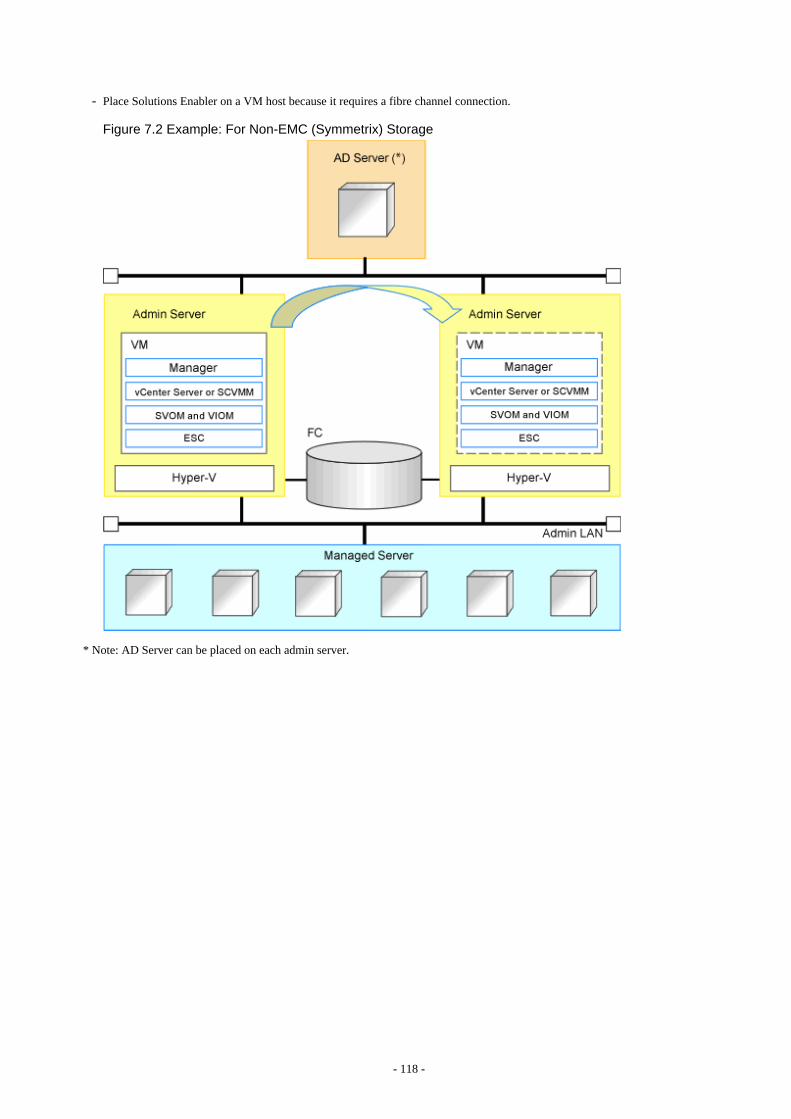
- Place Solutions Enabler on a VM host because it requires a fibre channel connection.
Figure 7.2 Example: For Non-EMC (Symmetrix) Storage
* Note: AD Server can be placed on each admin server.
- 118 -

Figure 7.3 Example: For EMC (Symmetrix) Storage
* Note: AD Server can be placed on each admin server.
- 119 -
Chapter 8 Defining and Configuring the ServerEnvironment
This section explains how to define and configure server environments.
8.1 Defining the Server EnvironmentThis section explains how to define setting values for server environments.
In this product, it corresponds to the following kind of servers. Decide the value to set for the server according to the kind of the server.
- Blade Servers
For details, refer to "8.1.1 Settings for Blade Servers".
- Rack Mount and Tower Servers
For details, refer to "8.1.2 Settings for Rack Mount and Tower Servers".
- PRIMEQUEST
For details, refer to "8.2.3 Configuring PRIMEQUEST".
- SPARC Enterprise M3000/T Series and FUJITSU M10-1/M10-4
For details, refer to "8.1.4 Setting Values for SPARC Enterprise (M3000/T5120/T5140/T5220/T5240/T5440) and FUJITSU M10-1/M10-4".
When switching over SPARC Enterprise servers, refer to "8.1.6 Settings when Switching Over Fujitsu M10/SPARC EnterpriseServers".
- SPARC Enterprise M4000/M5000/M8000/M9000 and SPARC M10-4S
Refer to "8.1.5 Setting Values for SPARC Enterprise M4000/M5000/M8000/M9000 and FUJITSU M10-4S".
When switching over SPARC Enterprise servers, refer to "8.1.6 Settings when Switching Over Fujitsu M10/SPARC EnterpriseServers".
Servers that do not use the server management software will be treated as "Rack Mount and Tower Servers".
For servers other than HP servers, a Baseboard Management Controller (hereinafter BMC) is used for server management.
When creating a physical L-Server, it is necessary to configure VIOM or HBA address rename settings as well as defining and configuringthe server environment.
For details, refer to "Prerequisites for Storage when Creating a Physical L-Server" in "D.3.1 Deciding the Storage Environment".
8.1.1 Settings for Blade ServersChoose values for the following management blade settings, given the following criteria:
Chassis name
This name is used to identify the chassis on the admin server. Each chassis name must be unique within the system.The first character must be alphabetic, and the name can contain up to 10 alphanumeric characters and hyphens ("-").
Admin IP address (IP address of the management blade)
These IP addresses can be used to communicate with the admin server.
SNMP community name
This community name can contain up to 32 alphanumeric characters, underscores ("_"), and hyphens ("-").
SNMP trap destination
This must be the IP address of the admin server.
- 120 -

Note
To enable server switchover and cloning between servers in different chassis, use the same SNMP community for each chassis.
8.1.2 Settings for Rack Mount and Tower ServersResource Orchestrator supports the following types of remote management controllers to manage servers.
- For PRIMERGY Servers
iRMC
- For HP Servers
iLO2 (integrated Lights-Out)
- For DELL or IBM Servers
BMC (Baseboard Management Controller)
Settings for Remote Management Controller
Choose values for the following remote management controller settings according to the criteria listed below.
Admin IP address (IP address of the IPMI controller)
These IP addresses can be used to communicate with the admin server.
User name
Name of the user account used to log in the remote management controller and gain control over the managed server.A user account with at least administration privileges within the remote management controller must be specified.The user name can contain up to 16 alphanumeric characters and symbols (ASCII characters 0x20 to 0x7e).If a user account with a name of 17 or more characters has already been set up, either create a new user account or rename it with aname of up to 16 characters.
Password
Password used to log in the remote management controller with the above user name.The user name can contain up to 16 alphanumeric characters and symbols (ASCII characters 0x20 to 0x7e).If a user account with password of 17 or more characters has already been set up, either create a new user account or change thepassword with one of up to 16 characters.
SNMP trap destination
The destination for SNMP traps sent by the remote management controller should be set as the admin server's IP address.
Settings for External Server Management Software (ServerView Agents)
For PRIMERGY servers, the server status can be monitored from external server management software (ServerView Agents). In that case,choose a value for the following setting.
SNMP community name
Name of the SNMP community used to communicate with the server management software (ServerView Agents) on the managedserver.This community name can contain up to 32 alphanumeric characters, underscores ("_"), and hyphens ("-").
Note
Use the same SNMP community for each server when using server switchover and cloning functions.
- 121 -

8.1.3 Settings for PRIMEQUESTChoose values for the following management board settings, given the following criteria:
Chassis name
This name is used to identify the PRIMEQUEST chassis on the admin server. Each chassis name must be unique within the system.The first character must be alphabetic, and the name can contain up to 10 alphanumeric characters and hyphens ("-").
Admin IP address (Virtual IP address of the management board)
These IP addresses can be used to communicate with the admin server.
User name
Name of the user account used to log into remote server management and gain control over the managed server.A user account with at least administration privileges within the remote server management must be specified.This user name must be between 8 and 16 alphanumeric characters long.
Password
Password used to log in the remote management controller with the above user name.This password must be between 8 and 16 alphanumeric characters long.
SNMP community name
This community name can contain up to 32 alphanumeric characters, underscores ("_"), and hyphens ("-").
SNMP trap destination
This must be the IP address of the admin server.
Note
- To enable server cloning between servers in different chassis, use the same SNMP community for each chassis.
- When using a PRIMEQUEST 2000 series, the following partition can be registered as a managed server.
- PPAR partition with "Extended Partitioning Mode" set to "Disable"
- Extended Partition configured on a PPAR partition with "Extended Partitioning Mode" set to "Enable"
Do not change the Extended Partitioning Mode after server registration.When the Extended Partitioning Mode is changed to "Enable" after registration, "Extended Partitioning Mode" is displayed, but PPARwith "Extended Partitioning Mode" displayed cannot be used.To change the Extended Partitioning Mode, delete the Extended Partitioning, then change the Extended Partitioning Mode and registerit again.
8.1.4 Setting Values for SPARC Enterprise (M3000/T5120/T5140/T5220/T5240/T5440) and FUJITSU M10-1/M10-4
Resource Orchestrator is able to manage SPARC Enterprise servers by using their XSCF interface for the M3000 series and the ILOMinterface for the T series as a remote management controller.
For SPARC Enterprise M3000 and SPARC M10-1/M10-4
For M3000, choose values for the following XSCF settings according to the criteria listed below.
- 122 -
IP address
These IP addresses can be used to communicate with the admin server.Set it to lan#0 of XSCF.
User name
Name of the user account used to log into XSCF and gain control over the managed server.A user account with "platadm" privileges within XSCF must be specified.The user name must start with an alphabet character, and can contain up to 31 alphanumeric characters, underscores ("_"), and hyphens("-").
The user name reserved for the system cannot be used. Create a different user name.For details, refer to the XSCF manual.
Password
Password used to log into the remote management controller with the above user name.The user password can contain up to 32 alphanumeric characters, blank spaces (" "), and any of the following characters."!", "@", "#", "$", "%", "^", "&", "*", "[", "]", "{", "}", "(", ")", "-", "+", "=", "~", ",", ">", "<", "/", "'", "?", ";", ":"
SNMP trap destination
The destination for SNMP traps sent by XSCF should be set to the admin server's IP address.
SNMP community name
Name of the SNMP community used to communicate with XSCF.This community name can contain up to 32 alphanumeric characters, underscores ("_"), and hyphens ("-").
For T Series
For the T series, choose values for the following ILOM settings according to the criteria listed below.
IP address
These IP addresses can be used to communicate with the admin server.
User name
The name of the user account used to log into ILOM and gain control over the managed server.A user account with Admin privileges within ILOM must be specified.The user name must start with an alphabet character, and can contain between 4 and 16 alphanumeric characters, underscores ("_"),and hyphens ("-").
Password
Password used to log into the remote management controller with the above user name.The user password can contain between 8 and 16 alphanumeric characters, blank spaces (" "), and any of the following characters."!", "@", "#", "$", "%", "^", "&", "*", "[", "]", "{", "}", "(", ")", "-", "+", "=", "~", ",", ">", "<", "/", "'", "?", ";", ":"
SNMP trap destination
The destination for SNMP traps sent by ILOM should be set to the admin server's IP address.
SNMP community name
Name of the SNMP community used to communicate with ILOM.This community name can contain up to 32 alphanumeric characters, underscores ("_"), and hyphens ("-").
8.1.5 Setting Values for SPARC Enterprise M4000/M5000/M8000/M9000 andFUJITSU M10-4S
Resource Orchestrator is able to manage SPARC Enterprise M4000/M5000/M8000/M9000 servers and servers in SPARC M10-4S byusing their XSCF interface as a remote management controller.Choose values for the following XSCF settings according to the criteria listed below.
- 123 -
Chassis name
This name is used to identify the chassis for SPARC Enterprise M4000/M5000/M8000/M9000 and SPARC M10-4S on the adminserver. Each chassis name must be unique within the system.The first character must be alphabetic, and the name can contain up to 10 alphanumeric characters and hyphens ("-").
Admin IP address
These IP addresses can be used to communicate with the admin server.Set it to lan#0 of XSCF.
User name
Name of the user account used to log into XSCF and gain control over the managed server.A user account with "platadm" privileges within XSCF must be specified.This name can contain up to 31 alphanumeric characters, hyphens ("-"), and underscores ("_").
The user name reserved for the system cannot be used. Create a different user name.For details, refer to the XSCF manual.
Password
Password used to log into the remote management controller with the above user name.The user password can contain up to 32 alphanumeric characters, blank spaces (" "), and any of the following characters."!", "@", "#", "$", "%", "^", "&", "*", "[", "]", "{", "}", "(", ")", "-", "+", "=", "~", ",", ">", "<", "/", "'", "?", ";", ":"
SNMP trap destination
The destination for SNMP traps sent by XSCF should be set to the admin server's IP address.
SNMP community name
Name of the SNMP community used to communicate with XSCF.This community name can contain up to 32 alphanumeric characters, underscores ("_"), and hyphens ("-").
Changing Monitoring Timeout Values of SPARC M10-4S Power Operations
When using SPARC M10-4S, the length of time from starting to completion of power operations increases proportionally to the scale ofBuilding Block configurations. Estimate the timeout values based on actual measured values, by performing power operations with anactual machine, after creating Building Block configuration environments.
The timeout values are changed for all M10-4S managed by the manager. When there are servers in multiple Building Block configurations,estimate the timeout values using the largest Building Block configuration environment.
When changing the timeout value, create the following definition file:
Storage Location of the Definition File
[Windows Manager]Installation_folder\SVROR\Manager\etc\customize_data
[Linux Manager]/etc/opt/FJSVrcvmr/customize_data
Definition File Name
power_timeout.rcxprop
Definition File Format
In the definition file, enter the configuration information (model name, timeout value of server powering on, timeout value of serverpowering off, etc.) for each server in a single line, separated by commas (","). Each line is entered in the following format.
model,boot_timeout,shutdown_timeout
- Blank spaces before and after commas (",") are ignored.
- When adding comments, start the line with a number sign ("#").
- 124 -
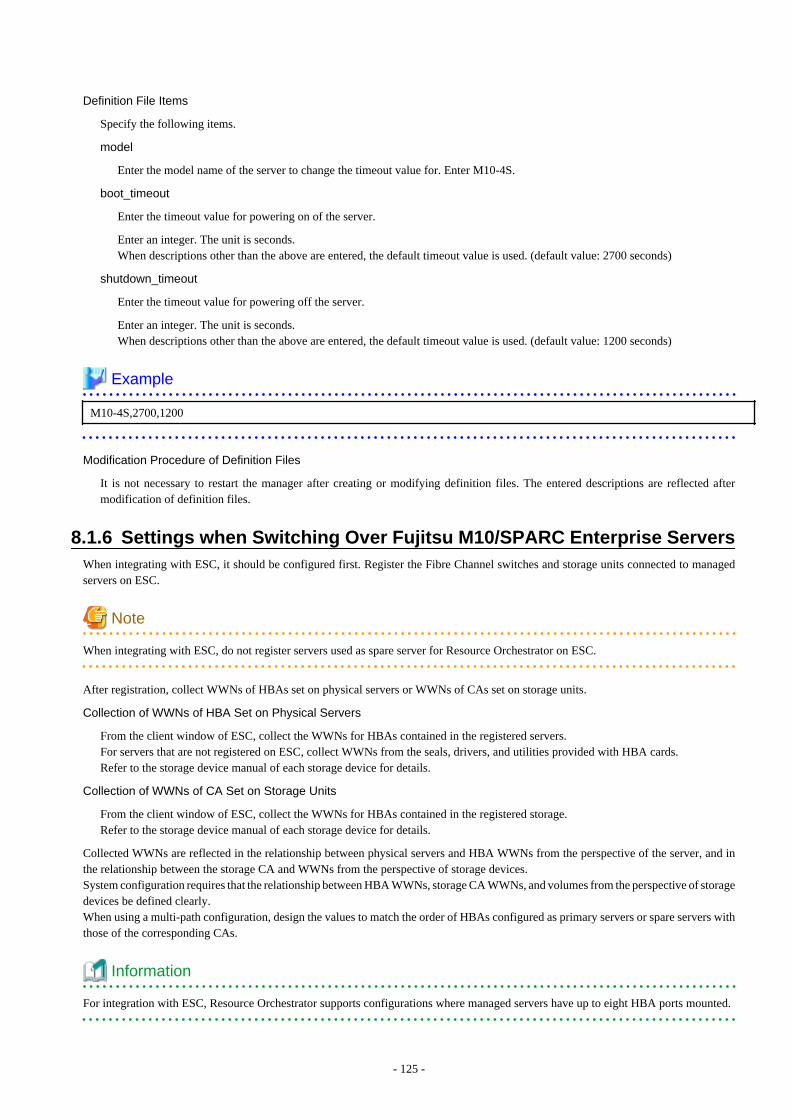
Definition File Items
Specify the following items.
model
Enter the model name of the server to change the timeout value for. Enter M10-4S.
boot_timeout
Enter the timeout value for powering on of the server.
Enter an integer. The unit is seconds.When descriptions other than the above are entered, the default timeout value is used. (default value: 2700 seconds)
shutdown_timeout
Enter the timeout value for powering off the server.
Enter an integer. The unit is seconds.When descriptions other than the above are entered, the default timeout value is used. (default value: 1200 seconds)
Example
M10-4S,2700,1200
Modification Procedure of Definition Files
It is not necessary to restart the manager after creating or modifying definition files. The entered descriptions are reflected aftermodification of definition files.
8.1.6 Settings when Switching Over Fujitsu M10/SPARC Enterprise ServersWhen integrating with ESC, it should be configured first. Register the Fibre Channel switches and storage units connected to managedservers on ESC.
Note
When integrating with ESC, do not register servers used as spare server for Resource Orchestrator on ESC.
After registration, collect WWNs of HBAs set on physical servers or WWNs of CAs set on storage units.
Collection of WWNs of HBA Set on Physical Servers
From the client window of ESC, collect the WWNs for HBAs contained in the registered servers.For servers that are not registered on ESC, collect WWNs from the seals, drivers, and utilities provided with HBA cards.Refer to the storage device manual of each storage device for details.
Collection of WWNs of CA Set on Storage Units
From the client window of ESC, collect the WWNs for HBAs contained in the registered storage.Refer to the storage device manual of each storage device for details.
Collected WWNs are reflected in the relationship between physical servers and HBA WWNs from the perspective of the server, and inthe relationship between the storage CA and WWNs from the perspective of storage devices.System configuration requires that the relationship between HBA WWNs, storage CA WWNs, and volumes from the perspective of storagedevices be defined clearly.When using a multi-path configuration, design the values to match the order of HBAs configured as primary servers or spare servers withthose of the corresponding CAs.
Information
For integration with ESC, Resource Orchestrator supports configurations where managed servers have up to eight HBA ports mounted.
- 125 -
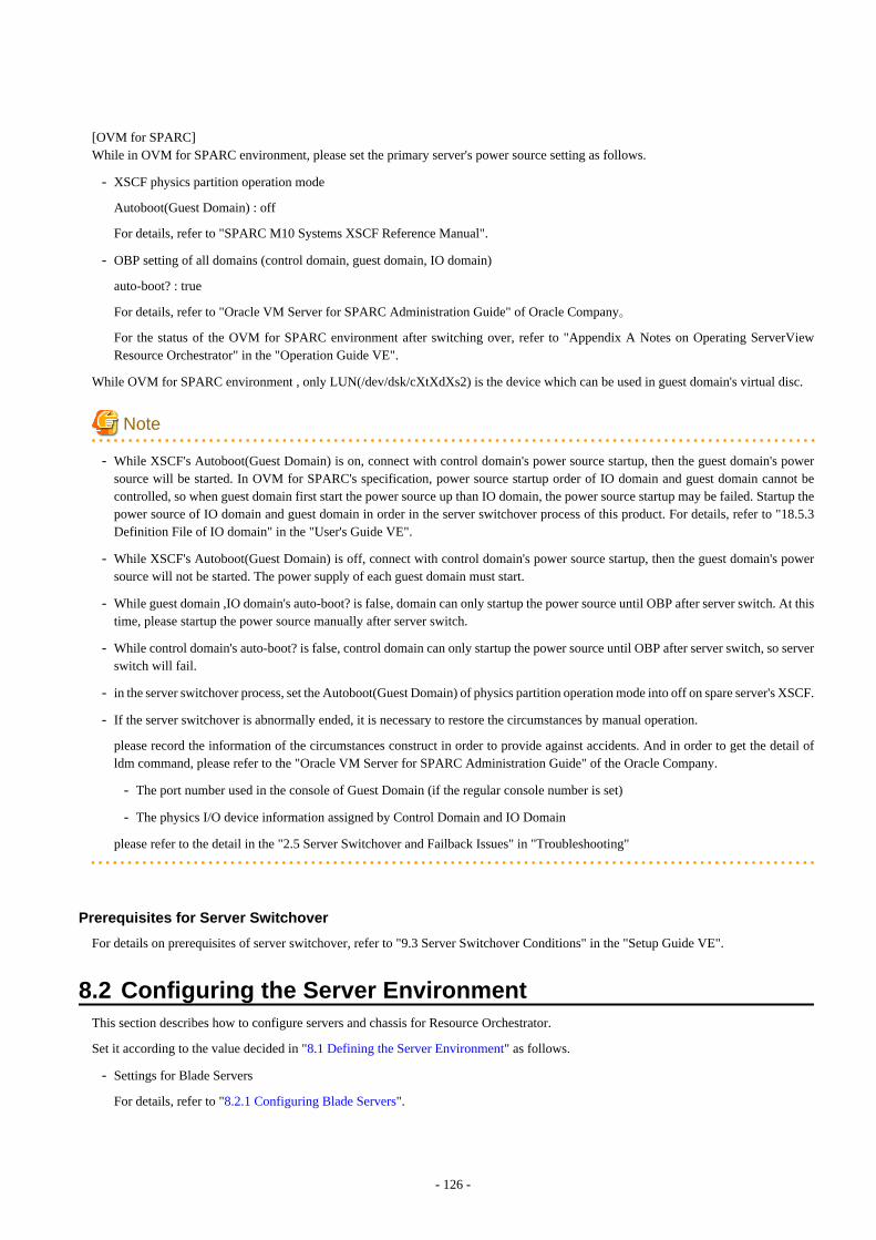
[OVM for SPARC]While in OVM for SPARC environment, please set the primary server's power source setting as follows.
- XSCF physics partition operation mode
Autoboot(Guest Domain) : off
For details, refer to "SPARC M10 Systems XSCF Reference Manual".
- OBP setting of all domains (control domain, guest domain, IO domain)
auto-boot? : true
For details, refer to "Oracle VM Server for SPARC Administration Guide" of Oracle Company。
For the status of the OVM for SPARC environment after switching over, refer to "Appendix A Notes on Operating ServerViewResource Orchestrator" in the "Operation Guide VE".
While OVM for SPARC environment , only LUN(/dev/dsk/cXtXdXs2) is the device which can be used in guest domain's virtual disc.
Note
- While XSCF's Autoboot(Guest Domain) is on, connect with control domain's power source startup, then the guest domain's powersource will be started. In OVM for SPARC's specification, power source startup order of IO domain and guest domain cannot becontrolled, so when guest domain first start the power source up than IO domain, the power source startup may be failed. Startup thepower source of IO domain and guest domain in order in the server switchover process of this product. For details, refer to "18.5.3Definition File of IO domain" in the "User's Guide VE".
- While XSCF's Autoboot(Guest Domain) is off, connect with control domain's power source startup, then the guest domain's powersource will not be started. The power supply of each guest domain must start.
- While guest domain ,IO domain's auto-boot? is false, domain can only startup the power source until OBP after server switch. At thistime, please startup the power source manually after server switch.
- While control domain's auto-boot? is false, control domain can only startup the power source until OBP after server switch, so serverswitch will fail.
- in the server switchover process, set the Autoboot(Guest Domain) of physics partition operation mode into off on spare server's XSCF.
- If the server switchover is abnormally ended, it is necessary to restore the circumstances by manual operation.
please record the information of the circumstances construct in order to provide against accidents. And in order to get the detail ofldm command, please refer to the "Oracle VM Server for SPARC Administration Guide" of the Oracle Company.
- The port number used in the console of Guest Domain (if the regular console number is set)
- The physics I/O device information assigned by Control Domain and IO Domain
please refer to the detail in the "2.5 Server Switchover and Failback Issues" in "Troubleshooting"
Prerequisites for Server Switchover
For details on prerequisites of server switchover, refer to "9.3 Server Switchover Conditions" in the "Setup Guide VE".
8.2 Configuring the Server EnvironmentThis section describes how to configure servers and chassis for Resource Orchestrator.
Set it according to the value decided in "8.1 Defining the Server Environment" as follows.
- Settings for Blade Servers
For details, refer to "8.2.1 Configuring Blade Servers".
- 126 -

- Settings for Rack Mount and Tower Servers
For details, refer to "8.2.2 Configuring Rack Mount and Tower Servers".
- Settings for PRIMEQUEST
For details, refer to "8.2.3 Configuring PRIMEQUEST".
- Configuring SPARC Enterprise M3000 and FUJITSU M10-1/M10-4
Please refer to the following.
"8.2.4 Configuring SPARC Enterprise M3000 and FUJITSU M10-1/M10-4"
"8.2.9 Configuring OBP (Open Boot Prom) Settings (Fujitsu M10/SPARC Enterprise)"
- Configuring SPARC Enterprise M4000/M5000/M8000/M9000 and FUJITSU M10-4S
Please refer to the following.
"8.2.5 Configuring SPARC Enterprise M4000/M5000/M8000/M9000 and FUJITSU M10-4S"
"8.2.9 Configuring OBP (Open Boot Prom) Settings (Fujitsu M10/SPARC Enterprise)"
- Settings for SPARC Enterprise T Series
Please refer to the following.
"8.2.6 Configuring SPARC Enterprise T5120/T5140/T5220/T5240/T5440"
"8.2.9 Configuring OBP (Open Boot Prom) Settings (Fujitsu M10/SPARC Enterprise)"
On the following servers, configure the settings as described in "8.2.7 Configuring BIOS Settings of Managed Servers".
- Blade Servers (only when not using VIOM)
- Settings for Rack Mount (when not using VIOM) and Tower Servers
- PRIMEQUEST
When an OS has been installed on the managed server, configure the settings as described in "8.2.8 Configuring OS Settings of ManagedServers".
When VMware ESXi has been installed on the managed server, configure the settings as described in "8.2.10 Configuring ServerViewOperations Manager (VMware ESXi)".
8.2.1 Configuring Blade ServersRefer to the management blade manual to apply the settings chosen in "8.1.1 Settings for Blade Servers" to the management blade.Note that the SNMP community must be set to Write (read and write) access.
- Admin IP address (IP address of the management blade)
- SNMP community name
- SNMP trap destination
This must be the IP address of the admin server.
Refer to the management blade manual to set the following SNMP agent settings.
- Set Agent SNMP Enable
Set to "enable".
- Set Agent SNMP Security Enable
Set to "disable".
- 127 -

Note
When powering off a chassis together with its enclosed server blades, servers are shut down using the graceful shutdown option of themanagement blade. To enable this feature, all servers within the chassis should have ServerView Agents installed.
8.2.2 Configuring Rack Mount and Tower ServersRefer to the remote management controller manual to configure the following on the IPMI controller.
- IP address
- User name
- Password
- SNMP trap destination
This must be the IP address of the admin server.
8.2.3 Configuring PRIMEQUESTRefer to the management board manual to apply the settings chosen in "8.1.3 Settings for PRIMEQUEST" to the management board.Note that the SNMP community must be set to Write (read and write) access.
- Admin IP address (Virtual IP address of the management board)
- User name
- Password
- SNMP community name
- SNMP trap destination
This must be the IP address of the admin server.
Enable the following function referring the instructions given in the management board's manual.
- SNMP Agent
8.2.4 Configuring SPARC Enterprise M3000 and FUJITSU M10-1/M10-4Refer to the management controller (XSCF) manual to apply the settings chosen in "8.1.4 Setting Values for SPARC Enterprise (M3000/T5120/T5140/T5220/T5240/T5440) and FUJITSU M10-1/M10-4" to the management controller.
- IP address
- User name
- Password
- SNMP community name
- SNMP trap destination
This must be the IP address of the admin server.
Refer to the remote management controller (XSCF) manual to configure the following on the IPMI controller.
- SNMP Agent (Also enable SP_MIB)
- SSH Service
- 128 -
- HTTPS Service
Note
- When assigning multiple IP addresses to multiple network interfaces on a XSCF module, ensure that the IP address used by ResourceOrchestrator is assigned to the first of those network interfaces.
- For SNMP settings in XSCF, enable SNMPv1 communication.
Set as follows to automatically start up the OS when powering on.
- Set the "Autoboot" of the Domain Mode to "on".
- Set the mode switch of the operator panel to "Locked" in OpenBoot configurations.
8.2.5 Configuring SPARC Enterprise M4000/M5000/M8000/M9000 andFUJITSU M10-4S
Refer to the management controller (XSCF) manual to apply the settings chosen in "8.1.5 Setting Values for SPARC Enterprise M4000/M5000/M8000/M9000 and FUJITSU M10-4S" to configure the following on the IPMI controller.Note that the SNMP community must be set to Write (read and write) access.
- Admin IP address (IP address of the remote management controller)
- User name
- Password
- SNMP community name
- SNMP trap destination
This must be the IP address of the admin server.
Refer to the instructions given in the XSCF manual and enable the following functions.
- SNMP Agent (Also enable SP_MIB)
- SSH Service
- HTTPS Service
- Domain Autoboot
Note
- For SNMP settings in XSCF, enable SNMPv1 communication.
Set as follows to automatically start up the OS when powering on.
- Set the "Autoboot" of the Domain Mode to "on".
- Set the mode switch of the operator panel to "Locked" in OpenBoot configurations.
- 129 -
8.2.6 Configuring SPARC Enterprise T5120/T5140/T5220/T5240/T5440Refer to the management controller (ILOM) manual to apply the settings chosen in "8.1.4 Setting Values for SPARC Enterprise (M3000/T5120/T5140/T5220/T5240/T5440) and FUJITSU M10-1/M10-4" to configure the following on the IPMI controller.
- IP address
- User name
- Password
- SNMP community name
- SNMP trap destination
This must be the IP address of the admin server.
Refer to the instructions given in the ILOM manual and enable the following functions.
- SNMP Agent
- SSH Configuration
- HTTPS Configuration
- IPMI Status
Note
For SNMP settings in ILOM, enable SNMPv1 communication.
8.2.7 Configuring BIOS Settings of Managed Servers
The following BIOS configurations must be modified.
System BIOS
This is the system BIOS for a managed server.Enable or disable FC-HBA BIOS as appropriate, and set up the appropriate boot order.
Note
- The BIOS settings of server blades include an option to automatically start up servers when their enclosing chassis is powered on.For details, refer to the server blade manual.
- For PRIMERGY BX900/BX400, when a PG-LND203 is mounted as the LAN expansion card of the server blade, do not set theNIC of the LAN expansion card as [disable] in the server blade's BIOS settings.The connections between server blades and LAN switch blades are not shown correctly, when [disable] is set.The following functions do not operate correctly.
- Changing and setting the VLAN for LAN switch blades (internal and external ports)
- Server switchover (changing network settings while a server is switched over)
- If "UEFI" and "Legacy" are displayed when configuring boot settings from the network interface, select [Legacy].
- Set PXE VLAN Support to [Disabled] when the server switchover method is HBA address rename.
FC-HBA BIOS
This is a BIOS setting that relates to FC-HBAs that have been installed as an expansion card in the blade server.Enable or disable SAN boot as well as the connection of a SAN storage environment by means of a Fibre Channel switch.
- 130 -
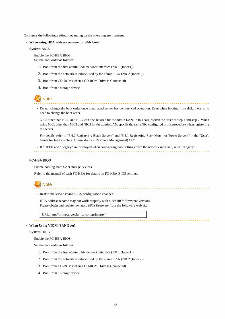
Configure the following settings depending on the operating environment.
- When using HBA address rename for SAN boot
System BIOS
Enable the FC-HBA BIOS.Set the boot order as follows:
1. Boot from the first admin LAN network interface (NIC1 (Index1))
2. Boot from the network interface used by the admin LAN (NIC2 (Index2))
3. Boot from CD-ROM (when a CD-ROM Drive is Connected)
4. Boot from a storage device
Note
- Do not change the boot order once a managed server has commenced operation. Even when booting from disk, there is noneed to change the boot order.
- NICs other than NIC1 and NIC2 can also be used for the admin LAN. In this case, switch the order of step 1 and step 2. Whenusing NICs other than NIC1 and NIC2 for the admin LAN, specify the same NIC configured in this procedure when registeringthe server.
For details, refer to "5.4.2 Registering Blade Servers" and "5.5.1 Registering Rack Mount or Tower Servers" in the "User'sGuide for Infrastructure Administrators (Resource Management) CE".
- If "UEFI" and "Legacy" are displayed when configuring boot settings from the network interface, select "Legacy".
FC-HBA BIOS
Enable booting from SAN storage devices.
Refer to the manual of each FC-HBA for details on FC-HBA BIOS settings.
Note
- Restart the server saving BIOS configuration changes.
- HBA address rename may not work properly with older BIOS firmware versions.Please obtain and update the latest BIOS firmware from the following web site.
URL: http://primeserver.fujitsu.com/primergy/
- When Using VIOM (SAN Boot)
System BIOS
Enable the FC-HBA BIOS.
Set the boot order as follows:
1. Boot from the first admin LAN network interface (NIC1 (Index1))
2. Boot from the network interface used by the admin LAN (NIC2 (Index2))
3. Boot from CD-ROM (when a CD-ROM Drive is Connected)
4. Boot from a storage device
- 131 -

Note
NICs other than NIC1 and NIC2 can also be used for the admin LAN. In this case, switch the order of step 1 and step 2. Whenusing NICs other than NIC1 and NIC2 for the admin LAN, specify the same NIC configured in this procedure when registeringthe server.
For details, refer to "5.4.2 Registering Blade Servers" and "5.5.1 Registering Rack Mount or Tower Servers" in the "User's Guidefor Infrastructure Administrators (Resource Management) CE".
FC-HBA BIOS
Apply the same settings as those described in the above "When using HBA address rename for SAN boot" section.
- When Using VIOM (iSCSI Boot)
System BIOS
Enable iSCSI boot for the NIC which is used for the iSCSI LAN.
Use the VIOM server profile for the iSCSI boot parameter settings.
For details on server profile setup, refer to the ServerView Virtual-IO Manager manual.
Set the boot order as follows:
1. Boot from the first admin LAN network interface (NIC1 (Index1))
2. Boot from the network interface used by the admin LAN (NIC2 (Index2))
3. Boot from the network interface used for the iSCSI LAN (NIC3(Index3))
4. Boot from the network interface used for the iSCSI LAN (NIC4(Index4))
Note
- Do not change the boot order once a managed server has commenced operation. Even when booting from disk, there is noneed to change the boot order.
- NICs other than NIC1 and NIC2 can also be used for the admin LAN. In this case, switch the order of step 1 and step 2. Whenusing NICs other than NIC1 and NIC2 for the admin LAN, specify the same NIC configured in this procedure when registeringthe server.
For details, refer to "5.4.2 Registering Blade Servers" and "5.5.1 Registering Rack Mount or Tower Servers" in the "User'sGuide for Infrastructure Administrators (Resource Management) CE".
- When using NIC3 or NIC4 for the admin LAN, use NICs other than NIC3 and NIC4 for the iSCSI LAN. In this case, switchthe order of step 3 and step 4.
FC-HBA BIOS
Disable the function.
8.2.8 Configuring OS Settings of Managed ServersWhen using the following functions, configure the OS to respond to ping commands.
- Auto-Recovery (for rack mount or tower servers)
- Configuration of monitoring information (ping monitoring)
- 132 -
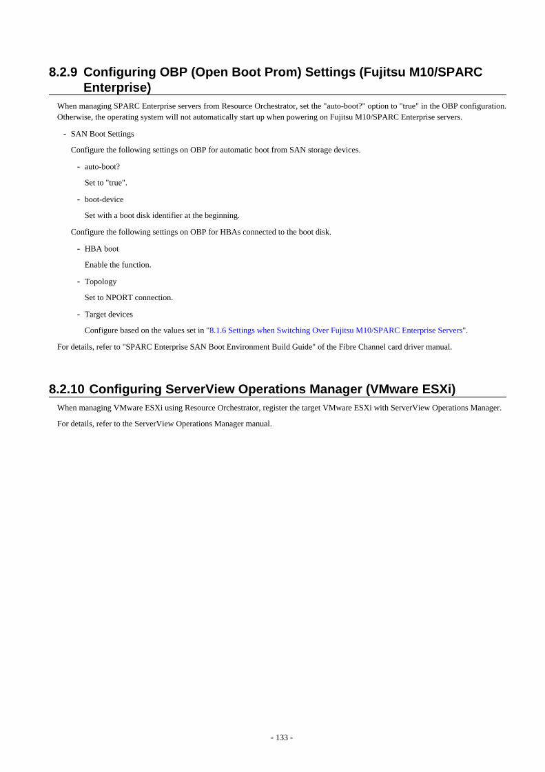
8.2.9 Configuring OBP (Open Boot Prom) Settings (Fujitsu M10/SPARCEnterprise)
When managing SPARC Enterprise servers from Resource Orchestrator, set the "auto-boot?" option to "true" in the OBP configuration.Otherwise, the operating system will not automatically start up when powering on Fujitsu M10/SPARC Enterprise servers.
- SAN Boot Settings
Configure the following settings on OBP for automatic boot from SAN storage devices.
- auto-boot?
Set to "true".
- boot-device
Set with a boot disk identifier at the beginning.
Configure the following settings on OBP for HBAs connected to the boot disk.
- HBA boot
Enable the function.
- Topology
Set to NPORT connection.
- Target devices
Configure based on the values set in "8.1.6 Settings when Switching Over Fujitsu M10/SPARC Enterprise Servers".
For details, refer to "SPARC Enterprise SAN Boot Environment Build Guide" of the Fibre Channel card driver manual.
8.2.10 Configuring ServerView Operations Manager (VMware ESXi)When managing VMware ESXi using Resource Orchestrator, register the target VMware ESXi with ServerView Operations Manager.
For details, refer to the ServerView Operations Manager manual.
- 133 -
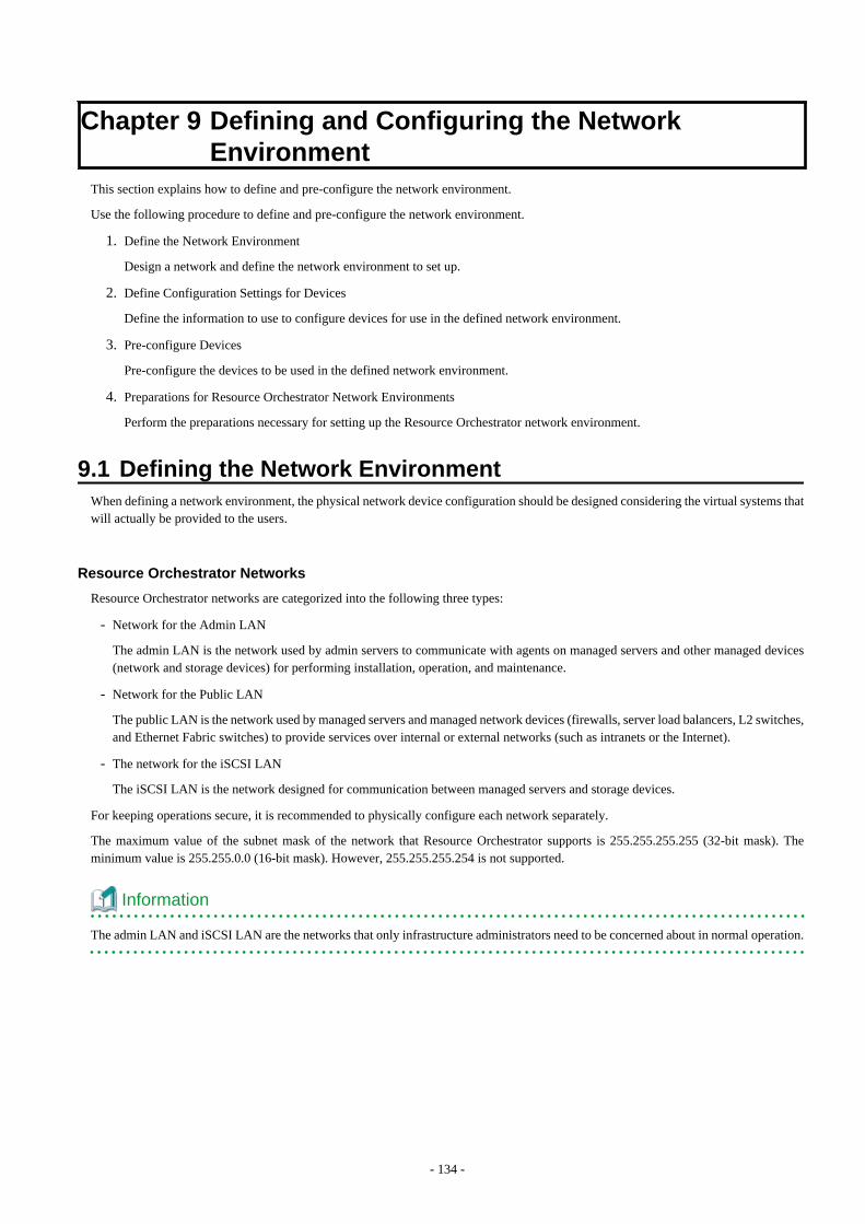
Chapter 9 Defining and Configuring the NetworkEnvironment
This section explains how to define and pre-configure the network environment.
Use the following procedure to define and pre-configure the network environment.
1. Define the Network Environment
Design a network and define the network environment to set up.
2. Define Configuration Settings for Devices
Define the information to use to configure devices for use in the defined network environment.
3. Pre-configure Devices
Pre-configure the devices to be used in the defined network environment.
4. Preparations for Resource Orchestrator Network Environments
Perform the preparations necessary for setting up the Resource Orchestrator network environment.
9.1 Defining the Network EnvironmentWhen defining a network environment, the physical network device configuration should be designed considering the virtual systems thatwill actually be provided to the users.
Resource Orchestrator Networks
Resource Orchestrator networks are categorized into the following three types:
- Network for the Admin LAN
The admin LAN is the network used by admin servers to communicate with agents on managed servers and other managed devices(network and storage devices) for performing installation, operation, and maintenance.
- Network for the Public LAN
The public LAN is the network used by managed servers and managed network devices (firewalls, server load balancers, L2 switches,and Ethernet Fabric switches) to provide services over internal or external networks (such as intranets or the Internet).
- The network for the iSCSI LAN
The iSCSI LAN is the network designed for communication between managed servers and storage devices.
For keeping operations secure, it is recommended to physically configure each network separately.
The maximum value of the subnet mask of the network that Resource Orchestrator supports is 255.255.255.255 (32-bit mask). Theminimum value is 255.255.0.0 (16-bit mask). However, 255.255.255.254 is not supported.
Information
The admin LAN and iSCSI LAN are the networks that only infrastructure administrators need to be concerned about in normal operation.
- 134 -
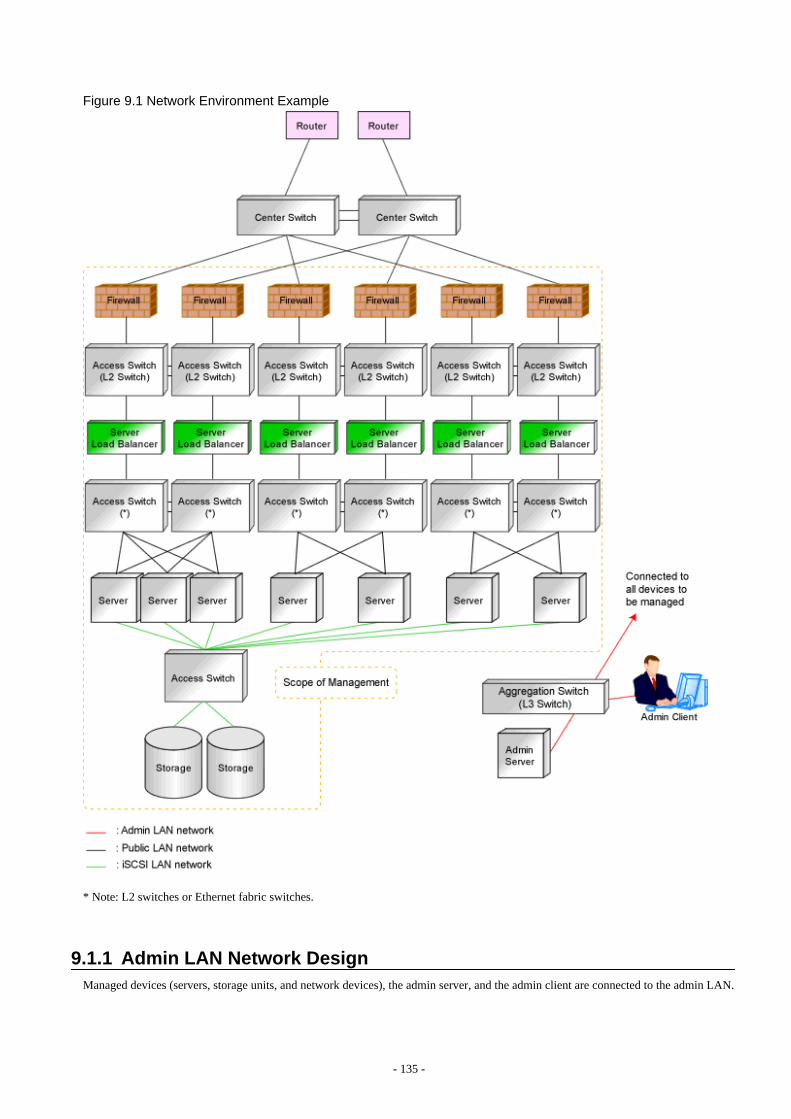
Figure 9.1 Network Environment Example
* Note: L2 switches or Ethernet fabric switches.
9.1.1 Admin LAN Network DesignManaged devices (servers, storage units, and network devices), the admin server, and the admin client are connected to the admin LAN.
- 135 -
An admin LAN can be divided into multiple admin LANs. Using this function, communication among tenants on physical L-Serversperformed through an admin LAN can be prevented.
When using multi-tenant functions, prepare a separate admin LAN for each tenant, and configure the admin LAN for each tenant fornetwork pools.
This improves the security of the network.
9.1.1.1 Information Necessary for DesignWhen designing an admin LAN, the following information needs to be defined beforehand:
- The number of tenants
- The number of VLAN IDs for use on the admin LAN
As the upper limit of the number of VLAN IDs varies depending on the device, when using devices that connect with both the adminand public LANs, ensure that the number does not exceed the maximum.
- The scope of VLAN IDs for use on the admin LAN
As the available VLAN ID range varies depending on the device, when using the devices that connect with both the admin and publicLANs, ensure that ranges do not overlap.
- The IP address range of the admin LAN
- Whether to configure admin route redundancy
9.1.1.2 Admin LAN for ServersFor each server, choose the network interfaces to use for the following purposes.
- Network interface assigned to the admin LAN
The number of network interfaces required for the admin server and managed servers can be determined as follows.
For a non-redundant configuration: one network interfaceFor a redundant configuration: two network interfaces
If HBA address rename is used, two network interfaces (named NIC1 and NIC2) are required regardless of network redundancy.For details, refer to "9.1.1.5 Required Network Configuration when Using HBA address rename".
For PRIMERGY Managed Servers
- For a non-redundant configuration
NIC1 (Index1)
- For a redundant configuration, or when using HBA address rename
NIC1 (Index1) and NIC2 (Index2)
The NICs above used by managed servers are the default values, and they can be changed when registering managed servers.
For details, refer to "5.4 When Using Blade Servers" and "5.5 When Using Rack Mount and Tower Servers" in the "User's Guide forInfrastructure Administrators (Resource Management) CE".
For PRIMEQUEST Managed Servers
- For a non-redundant configuration
The smallest NIC number of the GSPB allocated to a partition (*)
- For a redundant configuration
The smallest and the second smallest Onboard LAN NIC number of the GSPB allocated to a partition (*)
* Note: For the PRIMEQUEST 2000 series, take "GSPB" as meaning "IOU".
- 136 -
For Rack Mount or Tower Managed Servers
Check the alignment sequence and number of NICs on the back of rack mount or tower servers, and then decide the numbers of NICsspecified for the admin LAN using consecutive numbers starting with 1 (such as 1, 2,...).
- For a non-redundant configuration
NIC 1
- For a redundant configuration
NIC 1 and NIC 2
Choose the following settings to fit the system environment.
- Whether to use Admin LAN redundancy
Perform the redundancy of the admin LAN as below.
- For physical L-Servers, use Intel PROSet, PRIMECLUSTER GLS, or Linux bonding.
- For VM hosts, perform redundancy according to the server virtualization software used.
- The network configuration for LAN switch blades
See
When the admin LAN is operated among multiple subnets, install DHCP servers referring to "2.1.1 Manager Installation [WindowsManager]" or "2.1.2 Manager Installation [Linux Manager]" in the "Setup Guide CE".
Note
- For the admin server, only a single IP address can be used on the admin LAN.
- A network address that was set when installing the manager has been registered as an admin LAN network resource.
- Change the admin LAN network resource specifications, and register the IP address of a device that is not managed by ResourceOrchestrator as an IP address to exclude from allocation.If the IP address is not registered, it may conflict with the IP addresses of devices that are not managed by Resource Orchestrator.
- When using blade servers, connecting the management blade to a LAN switch blade will make the management blade inaccessible inthe event of a LAN switch blade failure. Therefore, it is recommended that the management blade be connected to the admin LANusing a LAN switch outside the chassis.
- When performing I/O virtualization using HBA address rename, if specifying a 10Gbps expansion card (NIC) for the admin LAN,backup and restore, and cloning cannot be used.
- Do not use products or services that use the functions of other DHCP servers or PXE servers on the admin server.However, such products or services can be placed on the same network as Resource Orchestrator managers. In this case, configurethe managed server for Resource Orchestrator to be excluded from being managed by any other DHCP server.
- Do not configure multiple IP addresses for network interfaces used on the admin LAN.
- When the same cloning image is deployed to multiple servers, IGMP snooping should be enabled on admin LAN switches. If IGMPsnooping is not enabled, transfer performance may deteriorate in the following cases:
- When ports with different speeds co-exist in the same network
- When multiple image operations are being executed simultaneously
- For PRIMERGY BX900/BX400 LAN switch blades operating in IBP mode, the admin LAN should not be included in the ServiceLANor the ServiceVLAN group configuration.
- 137 -
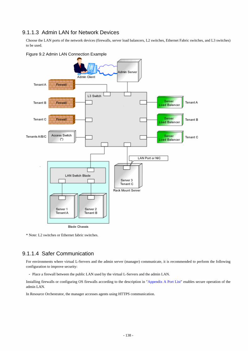
9.1.1.3 Admin LAN for Network DevicesChoose the LAN ports of the network devices (firewalls, server load balancers, L2 switches, Ethernet Fabric switches, and L3 switches)to be used.
Figure 9.2 Admin LAN Connection Example
* Note: L2 switches or Ethernet fabric switches.
9.1.1.4 Safer CommunicationFor environments where virtual L-Servers and the admin server (manager) communicate, it is recommended to perform the followingconfiguration to improve security:
- Place a firewall between the public LAN used by the virtual L-Servers and the admin LAN.
Installing firewalls or configuring OS firewalls according to the description in "Appendix A Port List" enables secure operation of theadmin LAN.
In Resource Orchestrator, the manager accesses agents using HTTPS communication.
- 138 -
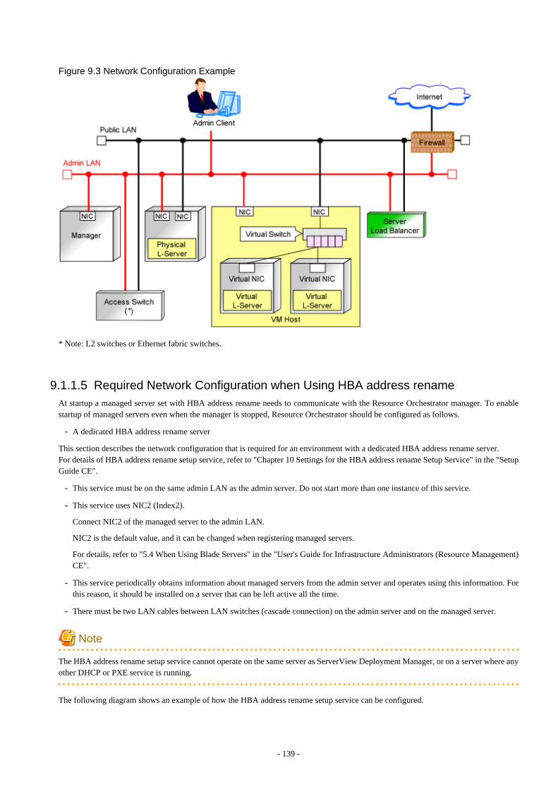
Figure 9.3 Network Configuration Example
* Note: L2 switches or Ethernet fabric switches.
9.1.1.5 Required Network Configuration when Using HBA address renameAt startup a managed server set with HBA address rename needs to communicate with the Resource Orchestrator manager. To enablestartup of managed servers even when the manager is stopped, Resource Orchestrator should be configured as follows.
- A dedicated HBA address rename server
This section describes the network configuration that is required for an environment with a dedicated HBA address rename server.For details of HBA address rename setup service, refer to "Chapter 10 Settings for the HBA address rename Setup Service" in the "SetupGuide CE".
- This service must be on the same admin LAN as the admin server. Do not start more than one instance of this service.
- This service uses NIC2 (Index2).
Connect NIC2 of the managed server to the admin LAN.
NIC2 is the default value, and it can be changed when registering managed servers.
For details, refer to "5.4 When Using Blade Servers" in the "User's Guide for Infrastructure Administrators (Resource Management)CE".
- This service periodically obtains information about managed servers from the admin server and operates using this information. Forthis reason, it should be installed on a server that can be left active all the time.
- There must be two LAN cables between LAN switches (cascade connection) on the admin server and on the managed server.
Note
The HBA address rename setup service cannot operate on the same server as ServerView Deployment Manager, or on a server where anyother DHCP or PXE service is running.
The following diagram shows an example of how the HBA address rename setup service can be configured.
- 139 -
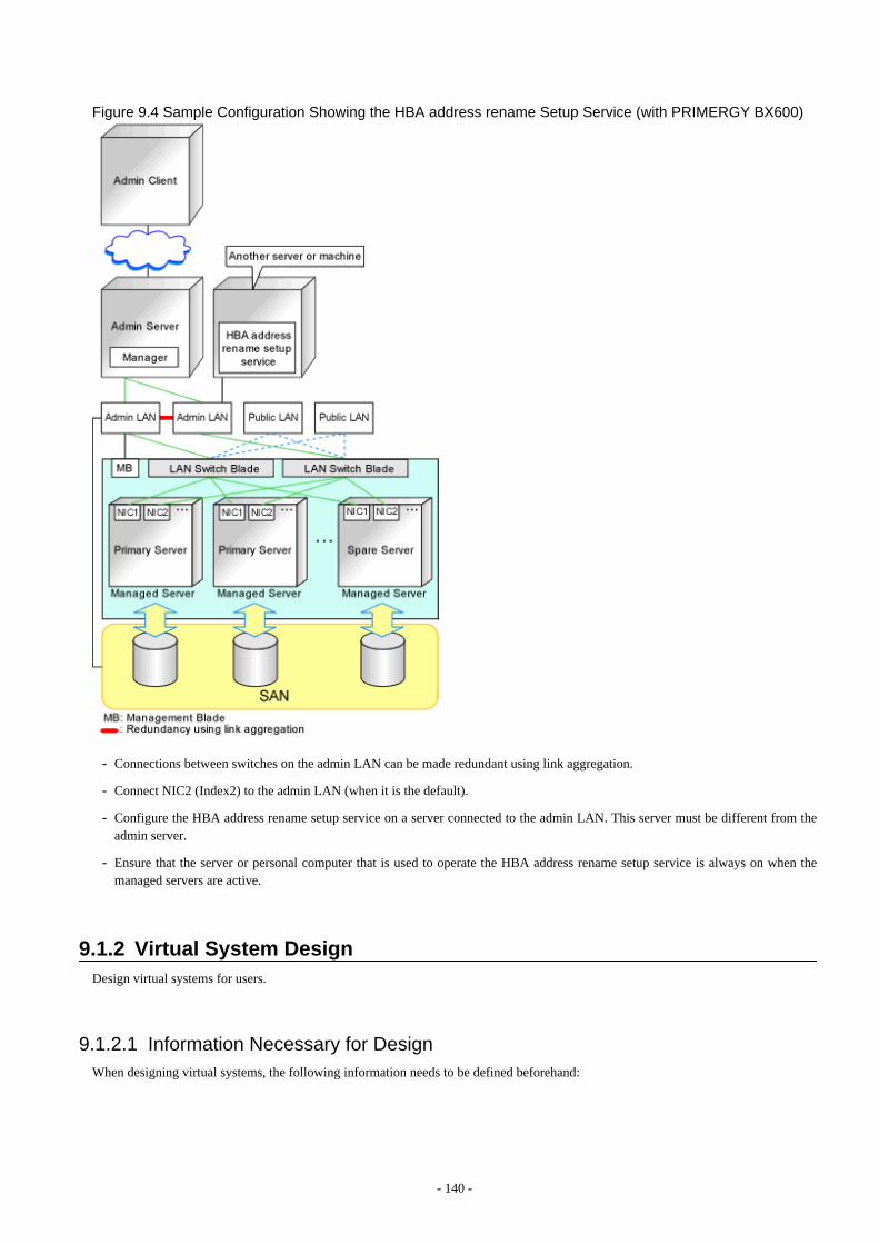
Figure 9.4 Sample Configuration Showing the HBA address rename Setup Service (with PRIMERGY BX600)
- Connections between switches on the admin LAN can be made redundant using link aggregation.
- Connect NIC2 (Index2) to the admin LAN (when it is the default).
- Configure the HBA address rename setup service on a server connected to the admin LAN. This server must be different from theadmin server.
- Ensure that the server or personal computer that is used to operate the HBA address rename setup service is always on when themanaged servers are active.
9.1.2 Virtual System DesignDesign virtual systems for users.
9.1.2.1 Information Necessary for DesignWhen designing virtual systems, the following information needs to be defined beforehand:
- 140 -
- Resource requirements
- Whether to use firewalls
If security must be maintained for each virtual system, deploy firewalls.
Firewalls should also be deployed when using a hierarchical configuration that establishes an intranet connected with a DMZ.
- Whether to use server load balancers
When providing services by virtualizing multiple servers as a single server in order to provide stable services and expand businessoperations flexibly, deploy server load balancers.
- Server type (physical L-Server or virtual L-Server)
- Whether to use iSCSI (Storage)
Information
When deploying both a firewall and a server load balancer, an L2 switch may be necessary between the firewall and server loadbalancer depending on device specifications. Therefore, check the specifications of the firewall and server load balancer beforehand.
- Communication route configuration
It is normal to use a redundant configuration for communication routes.
- 141 -
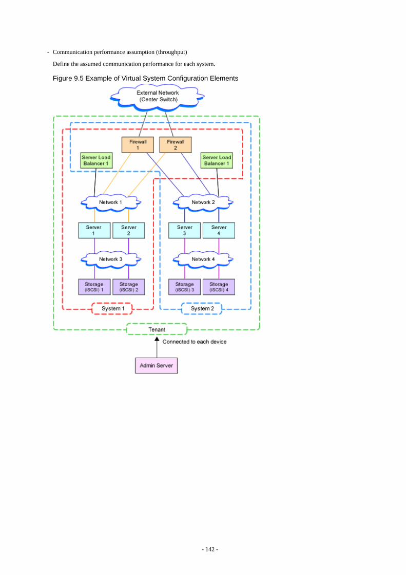
- Communication performance assumption (throughput)
Define the assumed communication performance for each system.
Figure 9.5 Example of Virtual System Configuration Elements
- 142 -

Figure 9.6 Example of Overall Configuration of a Virtual System (A Collective of Virtual System ConfigurationElements)
9.1.3 Physical Network Design for the Public LAN and iSCSI LANManaged devices (server machines and network devices) are connected using the public LAN.Managed devices (server machines and storage units) are connected using the iSCSI LAN.
Design of an iSCSI LAN is required to connect the iSCSI-enabled storage devices and servers to which physical L-Servers will be deployed.
9.1.3.1 Information Necessary for Designing a Public LANWhen designing a public LAN, the following information needs to be defined beforehand:
- The number of required devices (servers and network devices)
Define the required devices based on the designed virtual system.
The number of required devices should be estimated based on the following information:
- Performance requirements assumed during designing of the virtual system
- 143 -
- The number of planned tenants defined during designing of the admin LAN
- Specifications of devices to be used
- Specifications (including supported functions) required for the devices
- The number of VLAN IDs for use on the public LAN
As the upper limit of the number of VLAN IDs varies depending on the device, when using devices that connect with both the adminand public LANs, ensure that the number does not exceed the maximum.
- The VLAN ID range for use on the public LAN
As the available VLAN ID range varies depending on the device, when using the devices that connect with both the admin and publicLANs, ensure that ranges do not overlap.
- The IP address range of the public LAN
Design the address architecture to be allocated to the virtual system, and decide the required IP address range.
- When deploying a firewall
When using the address conversion function, define the virtual IP address.
- When deploying a server load balancer
Define the virtual IP address for the server load balancer
The IP address on the public LAN, designed and defined by the infrastructure administrator, is used by the virtual system configuredfor the tenant.Therefore, the infrastructure administrator must notify the tenant administrator of the IP address on the public LAN allocated to atenant.
- Whether to configure communication route redundancy
Whether to configure communication route redundancy should be decided based on the designed virtual system.
- The LAN ports or NICs to use
Define one of the following:
- For network devices, LAN ports other than the ones assigned to the admin LAN.
- For servers, NIC ports other than the ones assigned to the admin LAN.
When planning to use a rack mount server or tower server as a physical L-Server, define the following information:
- The NIC number of the rack mount server or tower server
Check the alignment sequence and number of NICs on the back of the rack mount or tower servers, and then choose the numbersof NICs to be specified when creating a physical L-Server, by consecutive numbers starting with 1 (such as 1, 2,...).
As the admin LAN uses small NIC numbers ("1" for non-redundant admin LANs or "1-2" for redundant LANs), ensure NICswith larger numbers are used.
Information
For blade servers, depending on the model of LAN switch blade used in the same chassis, certain network interfaces may not beavailable.
In this case, add expansion NICs and a LAN switch blade, or share the NIC used for the admin LAN.
All network interfaces shared between the admin LAN and the public LAN for managed servers should be configured with taggedVLAN IDs.
The NICs that are unavailable depend on the combination of the mounted LAN switch blade and blade server. For details, referto the manual of the LAN switch blade and blade server.
- 144 -
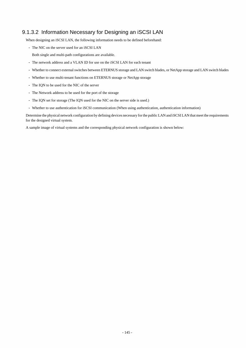
9.1.3.2 Information Necessary for Designing an iSCSI LANWhen designing an iSCSI LAN, the following information needs to be defined beforehand:
- The NIC on the server used for an iSCSI LAN
Both single and multi-path configurations are available.
- The network address and a VLAN ID for use on the iSCSI LAN for each tenant
- Whether to connect external switches between ETERNUS storage and LAN switch blades, or NetApp storage and LAN switch blades
- Whether to use multi-tenant functions on ETERNUS storage or NetApp storage
- The IQN to be used for the NIC of the server
- The Network address to be used for the port of the storage
- The IQN set for storage (The IQN used for the NIC on the server side is used.)
- Whether to use authentication for iSCSI communication (When using authentication, authentication information)
Determine the physical network configuration by defining devices necessary for the public LAN and iSCSI LAN that meet the requirementsfor the designed virtual system.
A sample image of virtual systems and the corresponding physical network configuration is shown below:
- 145 -
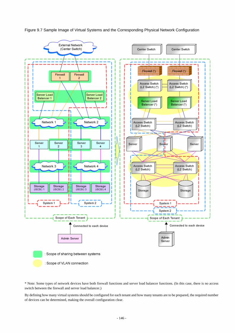
Figure 9.7 Sample Image of Virtual Systems and the Corresponding Physical Network Configuration
* Note: Some types of network devices have both firewall functions and server load balancer functions. (In this case, there is no accessswitch between the firewall and server load balancer.)
By defining how many virtual systems should be configured for each tenant and how many tenants are to be prepared, the required numberof devices can be determined, making the overall configuration clear.
- 146 -
An example of the overall configuration of the physical system is shown below:
Figure 9.8 Example of Overall Physical Network Configuration
*1: Some types of network devices have both firewall functions and server load balancer functions. (In this case, there is no access switchbetween the firewall and server load balancer.)*2: L2 switches or Ethernet fabric switches.
9.1.4 Relationship between Physical Network Configuration and ResourcesThis section explains the relationship between the defined physical system and the resources managed by Resource Orchestrator.
- 147 -

Using Resource Orchestrator, you can provide users with virtual systems and also operate those virtual systems. Therefore, it is necessaryto understand the relationship between physical systems and the resources configuring the virtual systems in advance.
Depending on how the physical devices are used in the virtual system, physical devices and resources can be in "one-to-one" or "one-to-n" relationships.
The relationship between physical networks and resources is shown below, using "Figure 9.8 Example of Overall Physical NetworkConfiguration" as an example.
- 148 -
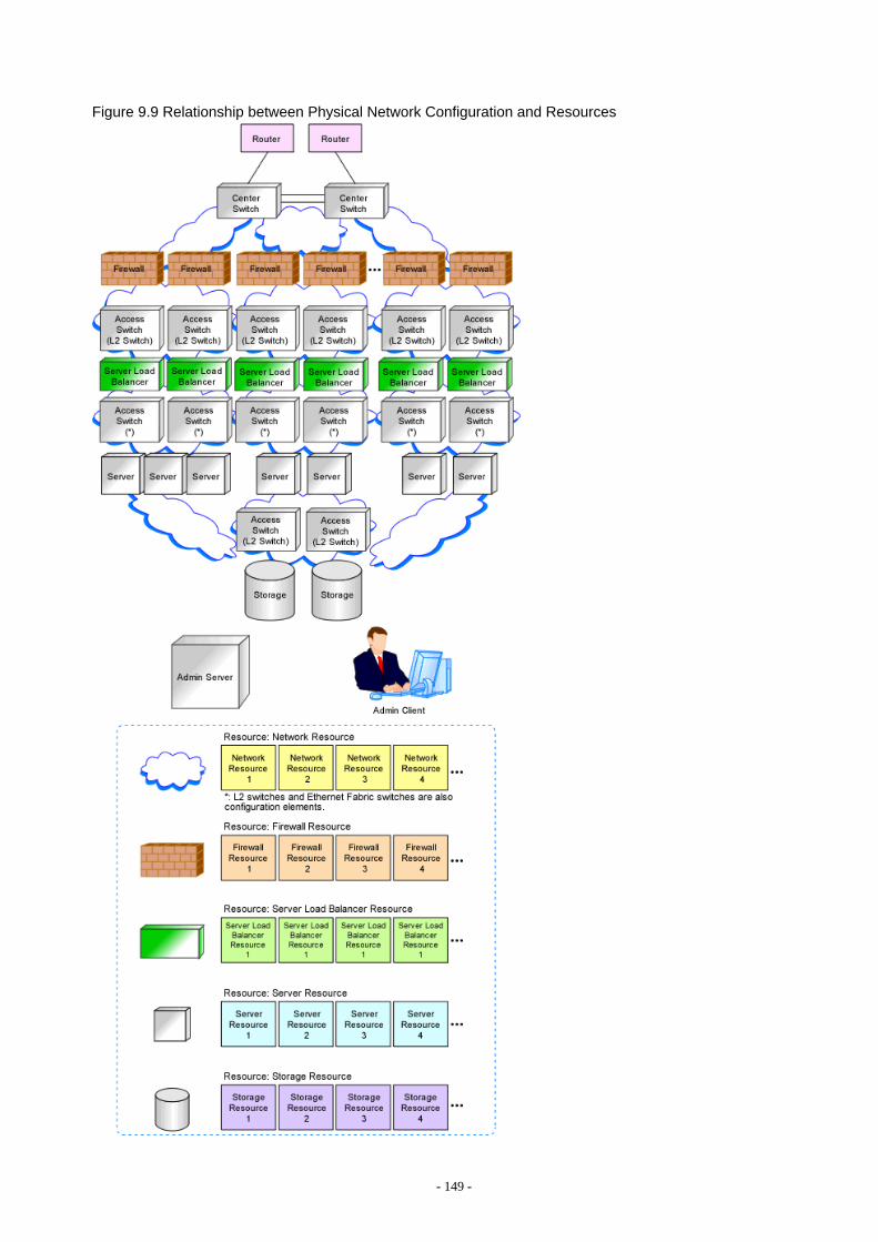
Figure 9.9 Relationship between Physical Network Configuration and Resources
- 149 -
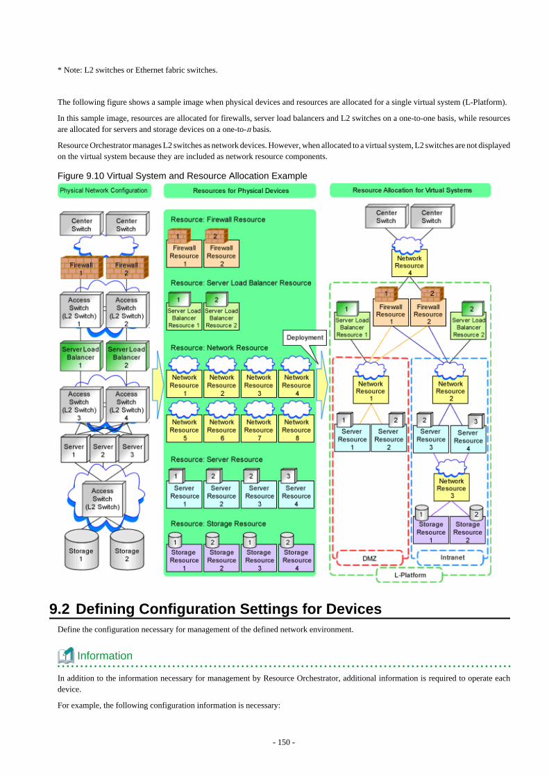
* Note: L2 switches or Ethernet fabric switches.
The following figure shows a sample image when physical devices and resources are allocated for a single virtual system (L-Platform).
In this sample image, resources are allocated for firewalls, server load balancers and L2 switches on a one-to-one basis, while resourcesare allocated for servers and storage devices on a one-to-n basis.
Resource Orchestrator manages L2 switches as network devices. However, when allocated to a virtual system, L2 switches are not displayedon the virtual system because they are included as network resource components.
Figure 9.10 Virtual System and Resource Allocation Example
9.2 Defining Configuration Settings for DevicesDefine the configuration necessary for management of the defined network environment.
Information
In addition to the information necessary for management by Resource Orchestrator, additional information is required to operate eachdevice.
For example, the following configuration information is necessary:
- 150 -
- Configuration information necessary for saving and referring to the logs output by individual devices
- Configuration information necessary for backing up and restoring the information from individual devices
Refer to the manuals of the devices to be used to check the information necessary for operation.
9.2.1 Settings for the Admin ServerDefine the following information to be configured on the admin server.
- Device name
- IP address used by the admin server for management purposes
Decide the IP address for the network interface used to communicate with managed servers and network devices.
9.2.2 Settings for Admin ClientsDefine the following information to be configured on the admin clients.
- Device name
- Routing information
When the admin IP address of the admin client is in a different subnet from that of the admin server, check the network device thatworks as the gateway, and define the routing information accordingly.
9.2.3 Settings for Managed Network DevicesDefine the following information to be configured on each of the network devices.
9.2.3.1 Settings for ManagementDefine configuration information necessary for management.
- Device name
Define the name of the managed device.This name can contain up to 32 alphanumeric characters (upper or lower case), underscores ("_"), hyphens ("-"), and periods (".").
- IP addresses used by managed network devices for management purposes
Choose an IP address to be used for communication with the admin server.
- SNMP community name
Define the name of the SNMP community to be used when collecting MIB information using the monitoring function of the networkdevice.This user name can contain up to 32 alphanumeric characters (upper or lower case), underscores ("_"), and hyphens ("-").
- Administrator information (user name and password)
- Login User Name
Define the login user name to be used for login to the network device.This user name can contain up to 32 alphanumeric characters (upper or lower case), underscores ("_"), and hyphens ("-").
- Password
Define the password for the login user name to be used for direct login to the network device.This user name can contain up to 32 alphanumeric characters (upper or lower case), underscores ("_"), and hyphens ("-").
- 151 -
- Administrator Password
Define the login password for the administrator to be used for logging into the network device as an administrator.This user name can contain up to 32 alphanumeric characters (upper or lower case), underscores ("_"), and hyphens ("-").
- SNMP host information
This must be the admin IP address of the admin server.
- SNMP trap destination
This must be the admin IP address of the admin server.
- Monitoring method (PING, SNMP)
Define the monitoring method for the network devices (firewalls, server load balancers, L2 switches, Ethernet fabrics, and managementhosts).Choose PING for monitoring active/inactive status, and choose SNMP for status monitoring.It is possible to monitor using only one method or both methods.
9.2.3.2 Settings for Pre-configurationDefine settings necessary for pre-configuration.
- Public LAN Pre-configuration Settings
Check the connection configuration of the LAN ports to be used for the public LAN to be connected with the center switches, anddefine the necessary settings accordingly.
- 152 -

- Admin LAN Pre-configuration Settings
Check the connection configuration of the LAN ports to be used for the admin LAN to be connected with the L3 switches, and definethe necessary settings accordingly.
Figure 9.11 Managed Device Pre-configuration Scope
* Note: L2 switches or Ethernet fabric switches.
- 153 -
Information
- Character limitations vary depending on the network device used.
For specific settings of individual devices, define the settings according to the specifications of the network devices, within thelimitations of types and number of characters described above.
The information necessary to be configured based on the public and admin LAN connection configurations also depends on thespecifications of network devices.
For details on the specifications for each network device, refer to the manual for each device.
- When targets to manage are the Ethernet Fabric switches, design of the following is required.
- Design the port types for each port of the relevant devices.
- When using virtual fabrics (VFAB), design all virtual fabrics to use in advance.
- When using virtual fabrics, it is recommended to use the LAN ports belonging to the default VFAB as the LAN ports for theadmin LAN.
For details on the outline of Ethernet Fabric switches, refer to "Appendix H Ethernet Fabric Devices".
- When targets to manage are IPCOM VX/IPCOM VA, design of the following is required.
- The VFAB VLAN ID of the virtual fabric must be same as the TPID of the VLAN ID defined in the virtual machine interfacedefinitions of IPCOM VX.For details on how to configure TPID, refer to the manual of each device.
- Use of virtual fabrics using Ethernet fabric switches is required.Design virtual fabrics to use for each IPCOM VA.During design, note the following information:
- Set the operation mode of the virtual fabric to Network mode.
- Configure the IEEE802.1ad frame communication port for the connection port with IPCOM VX.
Define the S-TAG value of the virtual fabric for the VLAN ID of the virtual machine interface of IPCOM VX.The S-TAG value of the virtual fabric can be calculated using the following formula:
- For defaultVFAB
2 fixed value
- For other than defaultVFAB
VFAB ID + 100
For details on virtual machine interface definitions for IPCOM VX, refer to the manuals of IPCOM VX.For the relationship between IPCOM VX/IPCOM VA and virtual fabrics, refer to "Appendix J IPCOM VX Series Devices".
9.2.3.3 Settings for Automatically Configured DevicesAs auto-configuration for network devices is performed with the user customization mode, the sample scripts provided with ResourceOrchestrator do not perform all definitions for network devices. When using the sample scripts, define the information necessary for auto-configuration of network devices.
Regarding the configuration provided by the sample scripts, refer to "Table G.2 Units for which Sample Scripts are Provided".
When performing auto-configuration for network devices using simple configuration mode, as the definition configuration scope is defined,it is necessary to perform pre-configuration as prerequisites of defined definitions. For details on the pre-configuration which can beconfigured using the simple configuration mode, refer to "Appendix I Auto-configuration and Operations of Network Devices UsingSimple Configuration Mode".
- 154 -
Firewalls
- When performing auto-configuration using user customization mode
In the sample scripts, only the network settings within the range of Resource Orchestrator management and firewall rules are auto-configured.Define the following settings for firewalls:
- Networks not managed by Resource Orchestrator (external interfaces etc.)
- Basic information (system definitions, redundant devices, interfaces, communication routes, etc.)
- When performing auto-configuration using simple configuration mode
Only the NS Option is the target of simple configuration mode.For details on pre-configuration for the NS Option, refer to "2.2.2 Preparations for NS Appliance" in the "NS Option Instruction".
Server Load Balancers
- When performing auto-configuration using user customization mode
In the sample scripts, only server load balancing rules and SSL accelerator settings are auto-configured.Therefore, define the following settings for server load balancers:
- Basic information (system definitions, redundant devices, interfaces, communication routes, etc.)
- Register the server certificate, error web page response file, etc.
- For devices which require configuration according to server certificate registration, configure security policies such as SSLconnection protocols, cipher suites, etc.
- When performing auto-configuration using simple configuration mode
There are no target devices.
L2 Switches
- When performing auto-configuration using user customization mode
In the sample scripts, only the VLAN IDs specified for network resources are auto-configured.Define the following settings for L2 switches:
- The definition of the interface to perform VLAN definition for
- The VLAN operation mode
- Cascade ports, etc
- When performing auto-configuration using simple configuration mode
There are no target devices.
9.2.4 Settings for Unmanaged Network DevicesDefine the information to be configured on each unmanaged network device.
- 155 -
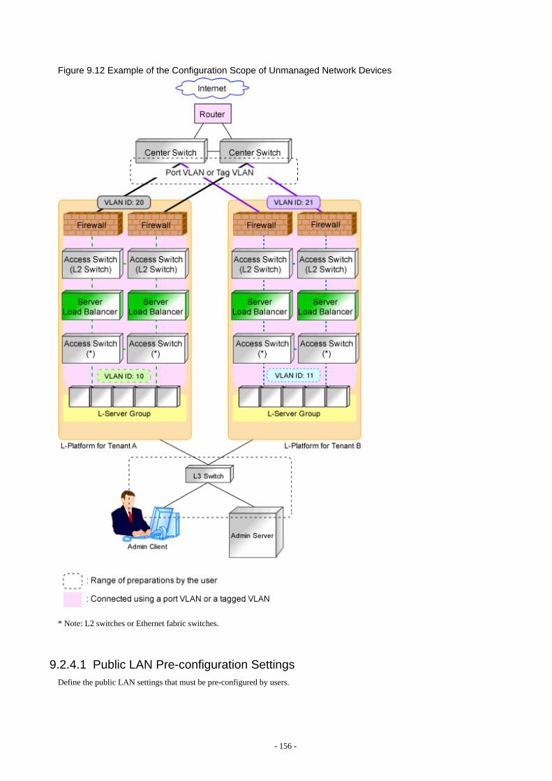
Figure 9.12 Example of the Configuration Scope of Unmanaged Network Devices
* Note: L2 switches or Ethernet fabric switches.
9.2.4.1 Public LAN Pre-configuration SettingsDefine the public LAN settings that must be pre-configured by users.
- 156 -
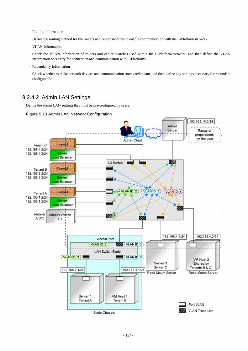
- Routing Information
Define the routing method for the routers and center switches to enable communication with the L-Platform network.
- VLAN Information
Check the VLAN information of routers and center switches used within the L-Platform network, and then define the VLANinformation necessary for connection and communication with L-Platforms.
- Redundancy Information
Check whether to make network devices and communication routes redundant, and then define any settings necessary for redundantconfiguration.
9.2.4.2 Admin LAN SettingsDefine the admin LAN settings that must be pre-configured by users.
Figure 9.13 Admin LAN Network Configuration
- 157 -
* Note: L2 switches or Ethernet fabric switches.
- Routing information
When the admin server and individual devices (servers, storage units, network devices, and admin clients) belong to different subnets,define the routing method on the L3 switch to enable communication between the admin server and individual devices using the adminLAN.
When using routing protocols (such as RIP and OSFP), define the information necessary for configuring dynamic routing. When notusing dynamic routing, define the settings for the routing information table.
In addition, it is necessary to configure the following multicast routing for managed resources from the admin server.
225.1.0.1 - 225.1.0.8
- VLAN information
Check the VLAN information of external ports of LAN switch blades and L3 switches used in the admin LAN network, and definethe settings (VLAN IDs). Set the ports to be used as trunk links when necessary.
- Redundancy information
Check whether to make network devices and communication routes redundant, and then define any settings necessary for redundantconfiguration.
- Access control information
When configuring access control on L3 switches, define the ports that allow connection, because it is necessary to allow connectionwith the ports used by Resource Orchestrator.
Refer to "Appendix A Port List", for details on the ports used by Resource Orchestrator.
Define whether to allow or block communication when the routing is operating in order to define the access control.
- When using the following functions, it is necessary to configure DHCP relay agents to enable the manager to receive DHCP requestsfrom managed servers belonging to different subnets.
- Backup and restoration of managed servers
- Collection and deployment of cloning images
- SAN boot using HBA address rename
- When using the HBA address rename setup service, it is necessary to configure DHCP relay agents to enable the HBA address renamesetup service to receive DHCP requests from managed servers belonging to different subnets.
- For information about multicast routing setting and DHCP relay agents, refer to the router manual.
9.2.5 Settings for Managed ServersDefine the following information to be configured on the servers to be managed.
- Device name
- IP addresses used by managed servers for management purposes
Choose an IP address to be used for communication with the admin server.
- IP Address of iSCSI Initiator
Choose an IP address for the network interface to use for communication with managed servers.
This is not necessary for servers for which iSCSI is not enabled.
Note
- IP addresses chosen for iSCSI should be static and do not used DHCP.
- 158 -
- When using a multi-path configuration using iSCSI, separate the networks using different ports.
Interface segments and virtual switches also need to be separated.
- When a physical L-Server uses the iSCSI storage, ensure that all of the IP addresses configured here are on the same subnet.
9.2.6 Settings for LAN Switch Blades on Managed Blade SystemsFor blade servers, also define the following information to be configured on LAN switch blades. For a LAN switch blade PY CB 10GbFEX Nexus B22, no admin IP address is required, thus the following information is not necessary:
- VLAN IDs for the admin LAN ports used to communicate with the admin server
- IP addresses used by managed network devices for management purposes
Choose an IP address to be used for communication with the admin server.
When using a LAN switch blade which operates in Converged Fabric mode, set an admin IP address that belongs to a different subnetfrom the one that the fabric representative virtual IP address and the domain representative virtual IP address belong to.
- SNMP community name
Define the name of the SNMP community to be used when collecting MIB information from the LAN switch blade.This user name can contain up to 32 alphanumeric characters (upper or lower case), underscores ("_"), and hyphens ("-").
- Administrator information (user name and password)
- Login User Name
Define the login user name to be used for direct login to the LAN switch blade.This user name can contain up to 64 alphanumeric characters (upper or lower case), underscores ("_"), and hyphens ("-").
- Password
Define the password of the login user name to be used for direct login to the LAN switch blade.This password can contain up to 80 alphanumeric characters (upper or lower case) and symbols (ASCII characters 0x20, 0x21,and 0x23 to 0x7e) with the exception of double quotation marks ( " ).
- Administrator Password
Define the login password for the administrator to be used for directly logging into the LAN switch blade as an administrator.This password can contain up to 80 alphanumeric characters (upper or lower case) and symbols (ASCII characters 0x20, 0x21,and 0x23 to 0x7e) with the exception of double quotation marks ( " ).
- SNMP trap destination
This must be the admin IP address of the admin server.
9.2.7 Network Settings for Managed Storage UnitsDefine the following information to be configured on storage units.
- Device name
- IP address used by managed storage for management purposes
Choose an IP address to be used for communication with the admin server.
- IP address of iSCSI target
Define the IP address of the storage unit with which the iSCSI initiator will communicate.
This is not necessary for storage units for which iSCSI is not enabled.
- 159 -

Note
- IP addresses chosen for iSCSI should be static and do not used DHCP.
- When using a multi-path configuration, separate the networks using different ports.
- When a physical L-Server uses the iSCSI storage, ensure that all of the IP addresses configured here are on the same subnet.
9.2.8 Network Settings for Other Managed HardwareDefine the following information to be configured on each of the other hardware devices.
Other hardware devices include "server management units", "power monitoring devices", etc.
- Device name
- IP addresses used by other hardware devices for management purposes
Choose an IP address to be used for communication with the admin server.
9.3 Pre-configuring DevicesConfigure defined setting information.
9.3.1 Pre-configuring Admin ServersConfigure the information defined in "9.2.1 Settings for the Admin Server" on the admin server.
The admin IP address should be specified when installing the manager on the admin server.
For details on how to configure the other information on the admin server, refer to the manual of the admin server.
9.3.2 Pre-configuring Admin ClientsConfigure the information defined in "9.2.2 Settings for Admin Clients" on admin clients.
For details on how to configure information on admin clients, refer to the manual of the admin client.
9.3.3 Pre-configuring Managed Network DevicesConfigure the information defined in "9.2.3 Settings for Managed Network Devices" on network devices.
In order to track the network connections between managed servers (PRIMERGY BX series) and adjacent network devices (L2 switches,etc.), and display them in the NetworkViewer, the following protocols should be first enabled on each LAN switch blade and networkdevice.
- LLDP (Link Layer Discovery Protocol)
- CDP (Cisco Discovery Protocol)
It is necessary to configure a port type for each port of the relevant devices, in order to correctly display the port information of EthernetFabric switches on the [Resource Details] tab.
Note
- The same protocol needs to be set on the LAN switch blade and the network devices it is connected to.
- 160 -
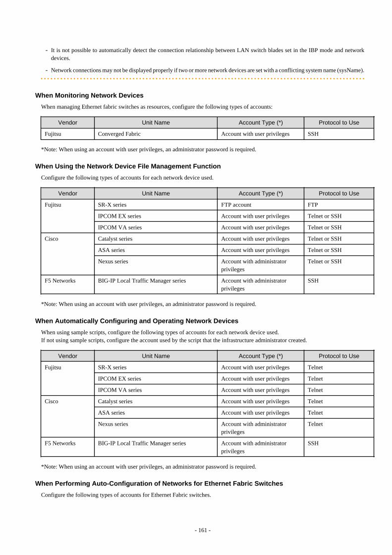
- It is not possible to automatically detect the connection relationship between LAN switch blades set in the IBP mode and networkdevices.
- Network connections may not be displayed properly if two or more network devices are set with a conflicting system name (sysName).
When Monitoring Network Devices
When managing Ethernet fabric switches as resources, configure the following types of accounts:
Vendor Unit Name Account Type (*) Protocol to Use
Fujitsu Converged Fabric Account with user privileges SSH
*Note: When using an account with user privileges, an administrator password is required.
When Using the Network Device File Management Function
Configure the following types of accounts for each network device used.
Vendor Unit Name Account Type (*) Protocol to Use
Fujitsu SR-X series FTP account FTP
IPCOM EX series Account with user privileges Telnet or SSH
IPCOM VA series Account with user privileges Telnet or SSH
Cisco Catalyst series Account with user privileges Telnet or SSH
ASA series Account with user privileges Telnet or SSH
Nexus series Account with administratorprivileges
Telnet or SSH
F5 Networks BIG-IP Local Traffic Manager series Account with administratorprivileges
SSH
*Note: When using an account with user privileges, an administrator password is required.
When Automatically Configuring and Operating Network Devices
When using sample scripts, configure the following types of accounts for each network device used.If not using sample scripts, configure the account used by the script that the infrastructure administrator created.
Vendor Unit Name Account Type (*) Protocol to Use
Fujitsu SR-X series Account with user privileges Telnet
IPCOM EX series Account with user privileges Telnet
IPCOM VA series Account with user privileges Telnet
Cisco Catalyst series Account with user privileges Telnet
ASA series Account with user privileges Telnet
Nexus series Account with administratorprivileges
Telnet
F5 Networks BIG-IP Local Traffic Manager series Account with administratorprivileges
SSH
*Note: When using an account with user privileges, an administrator password is required.
When Performing Auto-Configuration of Networks for Ethernet Fabric Switches
Configure the following types of accounts for Ethernet Fabric switches.
- 161 -
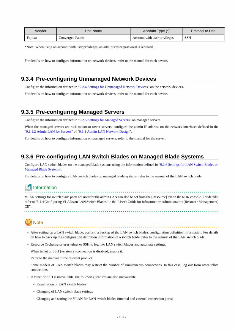
Vendor Unit Name Account Type (*) Protocol to Use
Fujitsu Converged Fabric Account with user privileges SSH
*Note: When using an account with user privileges, an administrator password is required.
For details on how to configure information on network devices, refer to the manual for each device.
9.3.4 Pre-configuring Unmanaged Network DevicesConfigure the information defined in "9.2.4 Settings for Unmanaged Network Devices" on the network devices.
For details on how to configure information on network devices, refer to the manual for each device.
9.3.5 Pre-configuring Managed ServersConfigure the information defined in "9.2.5 Settings for Managed Servers" on managed servers.
When the managed servers are rack mount or tower servers, configure the admin IP address on the network interfaces defined in the"9.1.1.2 Admin LAN for Servers" of "9.1.1 Admin LAN Network Design".
For details on how to configure information on managed servers, refer to the manual for the server.
9.3.6 Pre-configuring LAN Switch Blades on Managed Blade SystemsConfigure LAN switch blades on the managed blade systems using the information defined in "9.2.6 Settings for LAN Switch Blades onManaged Blade Systems".
For details on how to configure LAN switch blades on managed blade systems, refer to the manual of the LAN switch blade.
Information
VLAN settings for switch blade ports not used for the admin LAN can also be set from the [Resource] tab on the ROR console. For details,refer to "5.4.4 Configuring VLANs on LAN Switch Blades" in the "User's Guide for Infrastructure Administrators (Resource Management)CE".
Note
- After setting up a LAN switch blade, perform a backup of the LAN switch blade's configuration definition information. For detailson how to back up the configuration definition information of a switch blade, refer to the manual of the LAN switch blade.
- Resource Orchestrator uses telnet or SSH to log into LAN switch blades and automate settings.
When telnet or SSH (version 2) connection is disabled, enable it.
Refer to the manual of the relevant product.
Some models of LAN switch blades may restrict the number of simultaneous connections. In this case, log out from other telnetconnections.
- If telnet or SSH is unavailable, the following features are also unavailable.
- Registration of LAN switch blades
- Changing of LAN switch blade settings
- Changing and setting the VLAN for LAN switch blades (internal and external connection ports)
- 162 -
- Restoration of LAN switch blades
- Server switchover (changing network settings while a server is switched over)
- SSH connection (SSH version 2) can be selected for the following LAN switch blades.
- LAN switch blade PY CB Eth Switch/IBP 10Gb 18/8 (1.00 or later version)
- LAN switch blade PY CB Eth Switch 10/40Gb 18/8 (1.00 or later version)
- LAN switch blade PY CB Eth Switch/IBP 1Gb 36/8+2 (4.16 or later version)
- LAN switch blade PY CB Eth Switch/IBP 1Gb 36/12 (3.12 or later version)
- LAN switch blade PY CB Eth Switch/IBP 1Gb 18/6 (3.12 or later version)
- LAN switch blade PY CB DCB SW 10Gb 18/6/6 (2.1.1_fuj or later version)
- For PY CB Eth Switch/IBP 10Gb 18/8, the maximum unregistered VLAN ID is used for the "oob" port in the LAN switch blade.When the maximum VLAN ID, "4094", is set in the LAN switch blade and the "oob" port is used to connect the telnet, the followingfunctions cannot be used.
- Changing and setting the VLAN for LAN switch blades (internal and external connection ports)
- Restoration of LAN switch blades
- Server switchover (changing network settings while a server is switched over)
- When using end host mode, use the default pin-group and do not create new pin-groups. Also, disable the Automatic VLAN uplinkSynchronization (AVS) setting.This setting is not necessary, since there are no pin-group or AVS functions for PY CB Eth Switch/IBP 10Gb 18/8.
- When using the following LAN switch blades, do not enable classic-view:
- LAN switch blade PY CB Eth Switch/IBP 1Gb 36/8+2
- LAN switch blade PY CB Eth Switch/IBP 1Gb 36/12
- LAN switch blade PY CB Eth Switch/IBP 1Gb 18/6
- When using PY CB Eth Switch 10/40Gb 18/8+2, set the virtual IP address of Converged Fabric or IP address of oob.
- When the switch ID of PY CB Eth Switch/IBP 1Gb 36/8+2 is something other than 1, port and VLAN information cannot be displayedcorrectly. Set "1" for the Switch ID.
- The stacking function of LAN switch blades is not supported.
- If the VLAN settings are to be performed on the ports with link aggregation set on the following LAN switch blades, set the apparatusesas follows.
LAN switch blades
- PY CB Eth Switch/IBP 10Gb 18/8
Configuration
- LLDP (Link Layer Discovery Protocol)When setting LLDP, disable the setting for [VLAN name information].Make the other settings valid.
- When using a LAN switch blade PY CB 10Gb FEX Nexus B22, VLAN configuration cannot be performed on it, thus the followingfunctions cannot be used. Manually configure the VLAN from a Nexus 5000 series connected to the LAN switch blade PY CB 10GbFEX Nexus B22, in advance.
- Changing and setting the VLAN for LAN switch blades (internal and external connection ports)
- Restoration of LAN switch blades
However, settings other than VLAN settings should be made directly on the LAN switch blade.
- 163 -
Network Configuration of LAN Switch Blades (when using PRIMERGY BX Servers)
In a blade system environment, multiple subnets can be consolidated onto LAN switch blades by using VLANs.
For PRIMERGY BX900/BX400 LAN switch blades operating in IBP mode, the above can also be achieved by using port group settingsfor IBP instead of VLAN settings.
Each port of a LAN switch blade can be set with VLAN IDs.Only those ports set with a same VLAN ID can communicate with each other.Setting up different VLAN IDs then results in multiple subnets (one per VLAN ID) co-existing within the same switch.
Define the VLANs to set on both the internal (server blade side) and external connection ports of each LAN switch blade.
- Internal Connection Ports
Ensure that port VLANs are configured for the ports corresponding to the NICs connected to the admin LAN.
If NICs connected to the admin LAN are used for public LANs as well, configure tagged VLANs.
For the ports corresponding to the NICs connected to the public LAN, assign a VLAN ID (port or tagged VLAN) other than VLANID1 (the default VLAN ID) for each subnet.
Using tagged VLANs on LAN switch ports also requires configuring the network interfaces of managed servers with tagged VLANs.As Resource Orchestrator cannot set tagged VLANs to network interfaces on managed servers, this must be done manually.
- External Connection Ports
Choose the LAN switch blade ports to connect to external LAN switches, and the VLAN IDs to use for both the admin and publicLANs.
When choosing a tagged VLAN configuration, the VLAN ID chosen for a LAN switch blade's external port must be the same as thatused on its adjacent port on an external LAN switch.
When choosing a tagged VLAN configuration, the VLAN ID chosen for a LAN switch blade's external port must be the same as thatused on its adjacent port on an external LAN switch. It may be necessary to enable LLDP depending on the LAN switch blade.Refer to the manual for the LAN switch blade for information on how to configure link aggregation and to enable LLDP.
Note
- To change the VLAN ID for the admin LAN, perform the following.
1. Enable communications between the admin server and the LAN switch blade.
Manually change the following two settings.
- Change the VLAN ID of the external connection port(s) used for the admin LAN.
- Change the VLAN ID used by the admin IP address of the LAN switch blade.
2. Change the VLAN ID used by the managed server on the admin LAN.
- VLAN settings for LAN switch blades are not included in cloning images of physical servers. Configure VLAN settings for the targetservers before deploying a cloning image.
- In the following cases, VLANs cannot be configured using the ROR console.
- Configuring VLANs on external connection ports
- Link state group
- Port backup function
- Configuring VLANs on external and internal connection ports
- Deactivated (depends on LAN switch blade model)
- Each port VLAN configuration must meet all of the conditions below.
- Do not configure more than one port VLAN.
- Do not configure the same VLAN ID for the port VLAN and the tagged VLAN.
- 164 -
- Mount the following LAN switch blades in the connection blade slots except for CB5/6 when using a PRIMERGY BX900 chassis.
- LAN switch blade PY CB Eth Switch/IBP 1Gb 36/8+2
- LAN switch blade PY CB Eth Switch/IBP 1Gb 36/12
- LAN switch blade PY CB Eth Switch/IBP 1Gb 18/6
- When using a LAN switch blade PY CB 10Gb FEX Nexus B22 in a PRIMERGY BX900 chassis, server blades installed in slot 17 orslot 18 cannot use internal ports because the switch has only 16 internal ports.
Choose VLAN IDs and VLAN types for the ports on the switches connected to NICs on the physical servers.
- Physical server name
- NIC index
- VLAN ID
- VLAN type (port or tagged VLAN)
Information
On servers, operating systems associate each physical network interface with a connection name (Local area connection X in windowsand ethX in Linux).
If more than one network interface is installed, depending on the OS type and the order of LAN driver installation, the index numbers (X)displayed in their connection name may differ from their physically-bound index (defined by each interface's physical mount order).
The relations between physically-bound indexes and displayed connection names can be confirmed using OS-provided commands or tools.
For details, refer to network interface manuals.
Also, note that Resource Orchestrator uses the physical index of a network interface (based on physical mount order).
If the connection relationship (topology) between the managed server (PRIMERGY BX series) and neighboring network devices (L2switches, etc.) is to be displayed in the NetworkViewer, the following settings are required in the LAN switch blade and network deviceso that the topology can be automatically detected.
- LLDP (Link Layer Discovery Protocol)
- CDP (Cisco Discovery Protocol)
Note
- The same protocol needs to be set on the LAN switch blade and the network devices it is connected to.
- It is not possible to automatically detect the connection relationship between LAN switch blades set in the IBP mode and networkdevices.
- For the following LAN switch blades, the settings described below should be set to the same values in order to enable proper detectionof network links.
- LAN Switch Blades:
- PY CB Eth Switch/IBP 1Gb 36/12
- PY CB Eth Switch/IBP 1Gb 36/8+2
- PY CB Eth Switch/IBP 1Gb 18/6
- Expected Values:
- hostname set from the hostname command
- system name set from the snmp-server sysname command
- 165 -
Example
When setting both the hostname and system name to "swb1".
# hostname swb1# snmp-server sysname swb1
- For the following LAN switch blade, the settings described below should be set to the same value to enable proper detection of networklinks.
- LAN Switch Blades
- PY CB Eth Switch/IBP 10Gb 18/8
- Configuration
- Using the snmp agent address command, set the admin IP address of the LAN switch blade for the agent address.
- Network connections may not be displayed properly if two or more network devices are set with a conflicting system name (sysName).
[Windows] [Hyper-V]When using the backup, restore, or cloning functions, enable the managed server's NetBIOS over TCP/IP.
Note that the managed server should be restarted after enabling NetBIOS over TCP/IP.
Example of VLAN Network Configuration (with PRIMERGY BX600)
- 166 -

Figure 9.14 With Port VLANs
- 167 -
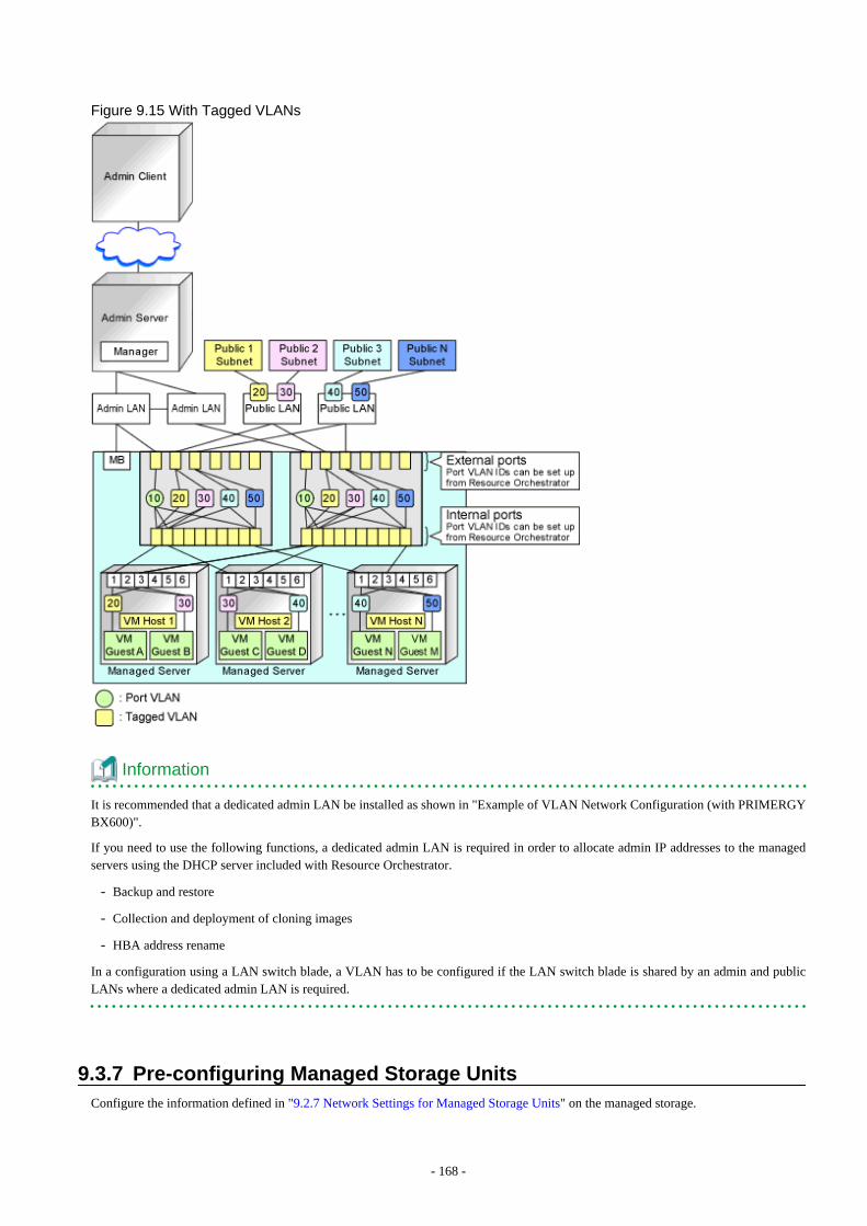
Figure 9.15 With Tagged VLANs
Information
It is recommended that a dedicated admin LAN be installed as shown in "Example of VLAN Network Configuration (with PRIMERGYBX600)".
If you need to use the following functions, a dedicated admin LAN is required in order to allocate admin IP addresses to the managedservers using the DHCP server included with Resource Orchestrator.
- Backup and restore
- Collection and deployment of cloning images
- HBA address rename
In a configuration using a LAN switch blade, a VLAN has to be configured if the LAN switch blade is shared by an admin and publicLANs where a dedicated admin LAN is required.
9.3.7 Pre-configuring Managed Storage UnitsConfigure the information defined in "9.2.7 Network Settings for Managed Storage Units" on the managed storage.
- 168 -
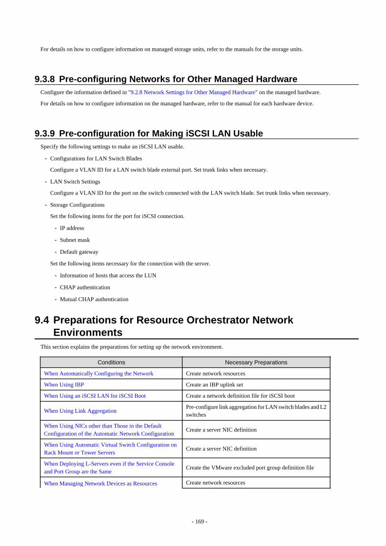
For details on how to configure information on managed storage units, refer to the manuals for the storage units.
9.3.8 Pre-configuring Networks for Other Managed HardwareConfigure the information defined in "9.2.8 Network Settings for Other Managed Hardware" on the managed hardware.
For details on how to configure information on the managed hardware, refer to the manual for each hardware device.
9.3.9 Pre-configuration for Making iSCSI LAN UsableSpecify the following settings to make an iSCSI LAN usable.
- Configurations for LAN Switch Blades
Configure a VLAN ID for a LAN switch blade external port. Set trunk links when necessary.
- LAN Switch Settings
Configure a VLAN ID for the port on the switch connected with the LAN switch blade. Set trunk links when necessary.
- Storage Configurations
Set the following items for the port for iSCSI connection.
- IP address
- Subnet mask
- Default gateway
Set the following items necessary for the connection with the server.
- Information of hosts that access the LUN
- CHAP authentication
- Mutual CHAP authentication
9.4 Preparations for Resource Orchestrator NetworkEnvironments
This section explains the preparations for setting up the network environment.
Conditions Necessary Preparations
When Automatically Configuring the Network Create network resources
When Using IBP Create an IBP uplink set
When Using an iSCSI LAN for iSCSI Boot Create a network definition file for iSCSI boot
When Using Link AggregationPre-configure link aggregation for LAN switch blades and L2switches
When Using NICs other than Those in the DefaultConfiguration of the Automatic Network Configuration
Create a server NIC definition
When Using Automatic Virtual Switch Configuration onRack Mount or Tower Servers
Create a server NIC definition
When Deploying L-Servers even if the Service Consoleand Port Group are the Same
Create the VMware excluded port group definition file
When Managing Network Devices as Resources Create network resources
- 169 -

Conditions Necessary Preparations
Configuring Definitions of the Network Device FileManagement Function
Registering External FTP Servers
When Automatically Configuring and Operating NetworkDevices
Create model definitions for the network devices
Create a folder for registering rulesets
Register sample scripts
9.4.1 When Automatically Configuring the NetworkBy connecting the NIC for an L-Server to a network resource, the following settings are automatically configured.
- Automatic VLAN Configuration for LAN Switch Blades (Physical/Virtual L-Servers)
- Network Configuration for Blade Servers (Physical/Virtual L-Servers)
- Network Configuration for Rack Mount or Tower Servers (Physical/Virtual L-Servers)
- IP Address Auto-Configuration (Virtual L-Servers)
- Automatic Configuration for L2 Switches
- Automatic Network Configuration for Ethernet Fabric Switches
9.4.1.1 Automatic VLAN Configuration for LAN Switch Blades (Physical/Virtual L-Servers)
VLANs are automatically configured on LAN switch blades.
When Using Something other than PY CB DCB SW 10 Gb 18/6/6 as a LAN Switch Blade
There are the following three types of firmware for LAN switch blades:
- Switch Firmware
Provides layer 2 switch functions.
- End-Host Firmware
This provides the layer 2 switch functionality and pin connection functionality.
- IBP Firmware
Delivers virtualization.
In Resource Orchestrator, operation of a LAN switch blade using Switch firmware is called Switch mode, operation using end-hostfirmware is called end-host mode, and operation using IBP firmware is called IBP mode.
For details, refer to the manual of the LAN switch blade.
- Switch Mode/End-Host Mode
VLANs are automatically configured for a LAN switch blade port.
- Automatic configuration for an internal connection port
Automatic configuration of tagged VLANs and port VLANs for server blade internal connection ports is performed.
- Automatic configuration for an uplink port
Automatic configuration of tagged VLANs that connect to network devices, such as access switches out of chassis, is performed.
- 170 -
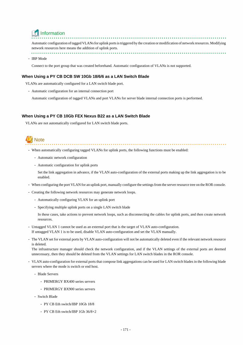
Information
Automatic configuration of tagged VLANs for uplink ports is triggered by the creation or modification of network resources. Modifyingnetwork resources here means the addition of uplink ports.
- IBP Mode
Connect to the port group that was created beforehand. Automatic configuration of VLANs is not supported.
When Using a PY CB DCB SW 10Gb 18/6/6 as a LAN Switch Blade
VLANs are automatically configured for a LAN switch blade port.
- Automatic configuration for an internal connection port
Automatic configuration of tagged VLANs and port VLANs for server blade internal connection ports is performed.
When Using a PY CB 10Gb FEX Nexus B22 as a LAN Switch Blade
VLANs are not automatically configured for LAN switch blade ports.
Note
- When automatically configuring tagged VLANs for uplink ports, the following functions must be enabled:
- Automatic network configuration
- Automatic configuration for uplink ports
Set the link aggregation in advance, if the VLAN auto-configuration of the external ports making up the link aggregation is to beenabled.
- When configuring the port VLAN for an uplink port, manually configure the settings from the server resource tree on the ROR console.
- Creating the following network resources may generate network loops.
- Automatically configuring VLAN for an uplink port
- Specifying multiple uplink ports on a single LAN switch blade
In these cases, take actions to prevent network loops, such as disconnecting the cables for uplink ports, and then create networkresources.
- Untagged VLAN 1 cannot be used as an external port that is the target of VLAN auto-configuration.If untagged VLAN 1 is to be used, disable VLAN auto-configuration and set the VLAN manually.
- The VLAN set for external ports by VLAN auto-configuration will not be automatically deleted even if the relevant network resourceis deleted.The infrastructure manager should check the network configuration, and if the VLAN settings of the external ports are deemedunnecessary, then they should be deleted from the VLAN settings for LAN switch blades in the ROR console.
- VLAN auto-configuration for external ports that compose link aggregations can be used for LAN switch blades in the following bladeservers where the mode is switch or end host.
- Blade Servers
- PRIMERGY BX400 series servers
- PRIMERGY BX900 series servers
- Switch Blade
- PY CB Eth switch/IBP 10Gb 18/8
- PY CB Eth switch/IBP 1Gb 36/8+2
- 171 -
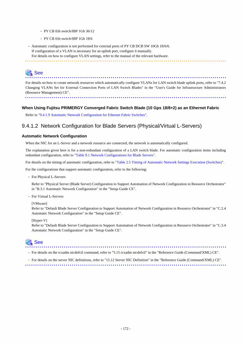
- PY CB Eth switch/IBP 1Gb 36/12
- PY CB Eth switch/IBP 1Gb 18/6
- Automatic configuration is not performed for external ports of PY CB DCB SW 10Gb 18/6/6.If configuration of a VLAN is necessary for an uplink port, configure it manually.For details on how to configure VLAN settings, refer to the manual of the relevant hardware.
See
For details on how to create network resources which automatically configure VLANs for LAN switch blade uplink ports, refer to "7.4.2Changing VLANs Set for External Connection Ports of LAN Switch Blades" in the "User's Guide for Infrastructure Administrators(Resource Management) CE".
When Using Fujitsu PRIMERGY Converged Fabric Switch Blade (10 Gps 18/8+2) as an Ethernet Fabric
Refer to "9.4.1.9 Automatic Network Configuration for Ethernet Fabric Switches".
9.4.1.2 Network Configuration for Blade Servers (Physical/Virtual L-Servers)
Automatic Network Configuration
When the NIC for an L-Server and a network resource are connected, the network is automatically configured.
The explanation given here is for a non-redundant configuration of a LAN switch blade. For automatic configuration items includingredundant configuration, refer to "Table 9.1 Network Configurations for Blade Servers".
For details on the timing of automatic configuration, refer to "Table 2.5 Timing of Automatic Network Settings Execution (Switches)".
For the configurations that support automatic configuration, refer to the following:
- For Physical L-Servers
Refer to "Physical Server (Blade Server) Configuration to Support Automation of Network Configuration in Resource Orchestrator"in "B.3.1 Automatic Network Configuration" in the "Setup Guide CE".
- For Virtual L-Servers
[VMware]Refer to "Default Blade Server Configuration to Support Automation of Network Configuration in Resource Orchestrator" in "C.2.4Automatic Network Configuration" in the "Setup Guide CE".
[Hyper-V]Refer to "Default Blade Server Configuration to Support Automation of Network Configuration in Resource Orchestrator" in "C.3.4Automatic Network Configuration" in the "Setup Guide CE".
See
- For details on the rcxadm nicdefctl command, refer to "5.15 rcxadm nicdefctl" in the "Reference Guide (Command/XML) CE".
- For details on the server NIC definitions, refer to "15.12 Server NIC Definition" in the "Reference Guide (Command/XML) CE".
- 172 -
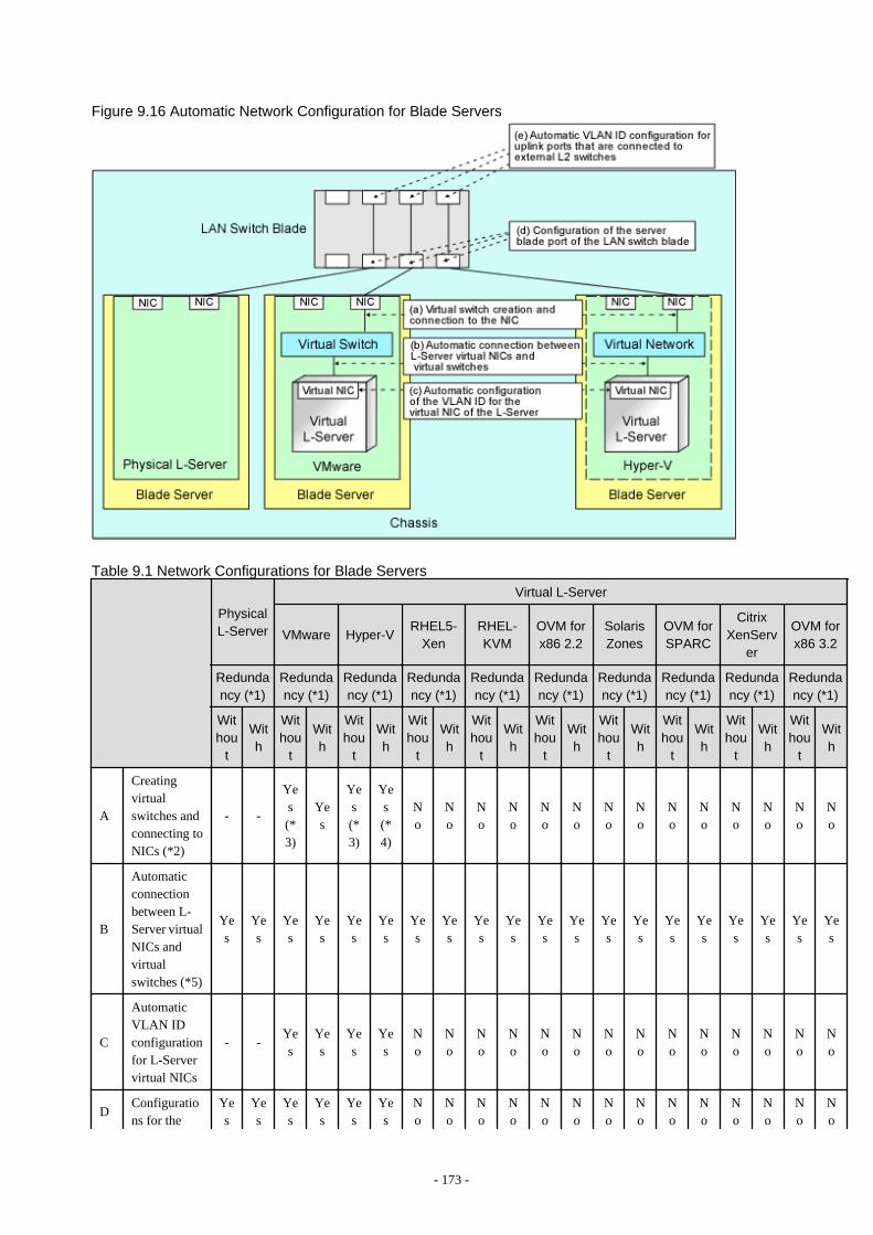
Figure 9.16 Automatic Network Configuration for Blade Servers
Table 9.1 Network Configurations for Blade Servers
PhysicalL-Server
Virtual L-Server
VMware Hyper-VRHEL5-
XenRHEL-KVM
OVM forx86 2.2
SolarisZones
OVM forSPARC
CitrixXenServ
er
OVM forx86 3.2
Redundancy (*1)
Redundancy (*1)
Redundancy (*1)
Redundancy (*1)
Redundancy (*1)
Redundancy (*1)
Redundancy (*1)
Redundancy (*1)
Redundancy (*1)
Redundancy (*1)
Withou
t
With
Withou
t
With
Withou
t
With
Withou
t
With
Withou
t
With
Withou
t
With
Withou
t
With
Withou
t
With
Withou
t
With
Withou
t
With
A
Creatingvirtualswitches andconnecting toNICs (*2)
- -
Yes(*3)
Yes
Yes(*3)
Yes(*4)
No
No
No
No
No
No
No
No
No
No
No
No
No
No
B
Automaticconnectionbetween L-Server virtualNICs andvirtualswitches (*5)
Yes
Yes
Yes
Yes
Yes
Yes
Yes
Yes
Yes
Yes
Yes
Yes
Yes
Yes
Yes
Yes
Yes
Yes
Yes
Yes
C
AutomaticVLAN IDconfigurationfor L-Servervirtual NICs
- -Yes
Yes
Yes
Yes
No
No
No
No
No
No
No
No
No
No
No
No
No
No
DConfigurations for the
Yes
Yes
Yes
Yes
Yes
Yes
No
No
No
No
No
No
No
No
No
No
No
No
No
No
- 173 -
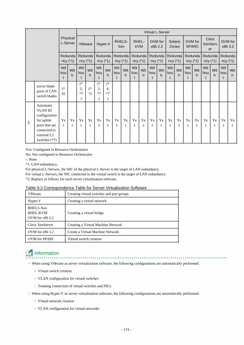
PhysicalL-Server
Virtual L-Server
VMware Hyper-VRHEL5-
XenRHEL-KVM
OVM forx86 2.2
SolarisZones
OVM forSPARC
CitrixXenServ
er
OVM forx86 3.2
Redundancy (*1)
Redundancy (*1)
Redundancy (*1)
Redundancy (*1)
Redundancy (*1)
Redundancy (*1)
Redundancy (*1)
Redundancy (*1)
Redundancy (*1)
Redundancy (*1)
Withou
t
With
Withou
t
With
Withou
t
With
Withou
t
With
Withou
t
With
Withou
t
With
Withou
t
With
Withou
t
With
Withou
t
With
Withou
t
With
server bladeports of LANswitch blades
(*6)
(*3,*7)
(*7)
(*3,*7)
(*4,*7)
E
AutomaticVLAN IDconfigurationfor uplinkports that areconnected toexternal L2switches (*7)
Yes
Yes
Yes
Yes
Yes
Yes
Yes
Yes
Yes
Yes
Yes
Yes
Yes
Yes
Yes
Yes
Yes
Yes
Yes
Yes
Yes: Configured in Resource OrchestratorNo: Not configured in Resource Orchestrator-: None*1: LAN redundancy.For physical L-Servers, the NIC of the physical L-Server is the target of LAN redundancy.For virtual L-Servers, the NIC connected to the virtual switch is the target of LAN redundancy.*2: Replace as follows for each server virtualization software.
Table 9.2 Correspondence Table for Server Virtualization Software
VMware Creating virtual switches and port groups
Hyper-V Creating a virtual network
RHEL5-XenRHEL-KVMOVM for x86 2.2
Creating a virtual bridge
Citrix XenServer Creating a Virtual Machine Network
OVM for x86 3.2 Create a Virtual Machine Network
OVM for SPARC Virtual switch creation
Information
- When using VMware as server virtualization software, the following configurations are automatically performed:
- Virtual switch creation
- VLAN configuration for virtual switches
- Teaming connection of virtual switches and NICs
- When using Hyper-V as server virtualization software, the following configurations are automatically performed:
- Virtual network creation
- VLAN configuration for virtual networks
- 174 -
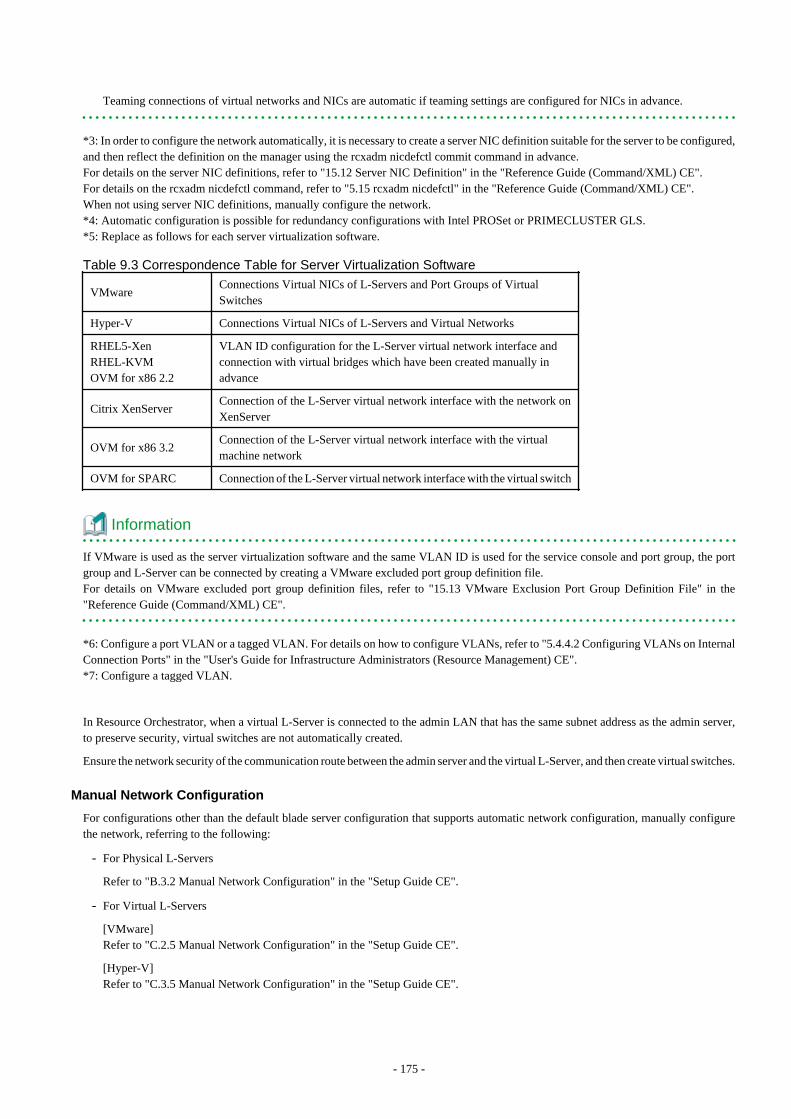
Teaming connections of virtual networks and NICs are automatic if teaming settings are configured for NICs in advance.
*3: In order to configure the network automatically, it is necessary to create a server NIC definition suitable for the server to be configured,and then reflect the definition on the manager using the rcxadm nicdefctl commit command in advance.For details on the server NIC definitions, refer to "15.12 Server NIC Definition" in the "Reference Guide (Command/XML) CE".For details on the rcxadm nicdefctl command, refer to "5.15 rcxadm nicdefctl" in the "Reference Guide (Command/XML) CE".When not using server NIC definitions, manually configure the network.*4: Automatic configuration is possible for redundancy configurations with Intel PROSet or PRIMECLUSTER GLS.*5: Replace as follows for each server virtualization software.
Table 9.3 Correspondence Table for Server Virtualization Software
VMwareConnections Virtual NICs of L-Servers and Port Groups of VirtualSwitches
Hyper-V Connections Virtual NICs of L-Servers and Virtual Networks
RHEL5-XenRHEL-KVMOVM for x86 2.2
VLAN ID configuration for the L-Server virtual network interface andconnection with virtual bridges which have been created manually inadvance
Citrix XenServerConnection of the L-Server virtual network interface with the network onXenServer
OVM for x86 3.2Connection of the L-Server virtual network interface with the virtualmachine network
OVM for SPARC Connection of the L-Server virtual network interface with the virtual switch
Information
If VMware is used as the server virtualization software and the same VLAN ID is used for the service console and port group, the portgroup and L-Server can be connected by creating a VMware excluded port group definition file.For details on VMware excluded port group definition files, refer to "15.13 VMware Exclusion Port Group Definition File" in the"Reference Guide (Command/XML) CE".
*6: Configure a port VLAN or a tagged VLAN. For details on how to configure VLANs, refer to "5.4.4.2 Configuring VLANs on InternalConnection Ports" in the "User's Guide for Infrastructure Administrators (Resource Management) CE".*7: Configure a tagged VLAN.
In Resource Orchestrator, when a virtual L-Server is connected to the admin LAN that has the same subnet address as the admin server,to preserve security, virtual switches are not automatically created.
Ensure the network security of the communication route between the admin server and the virtual L-Server, and then create virtual switches.
Manual Network Configuration
For configurations other than the default blade server configuration that supports automatic network configuration, manually configurethe network, referring to the following:
- For Physical L-Servers
Refer to "B.3.2 Manual Network Configuration" in the "Setup Guide CE".
- For Virtual L-Servers
[VMware]Refer to "C.2.5 Manual Network Configuration" in the "Setup Guide CE".
[Hyper-V]Refer to "C.3.5 Manual Network Configuration" in the "Setup Guide CE".
- 175 -
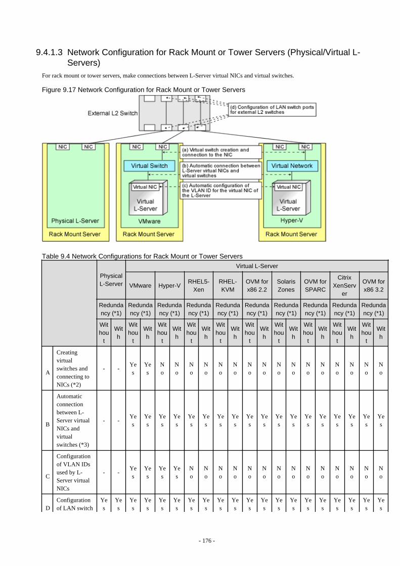
9.4.1.3 Network Configuration for Rack Mount or Tower Servers (Physical/Virtual L-Servers)
For rack mount or tower servers, make connections between L-Server virtual NICs and virtual switches.
Figure 9.17 Network Configuration for Rack Mount or Tower Servers
Table 9.4 Network Configurations for Rack Mount or Tower Servers
PhysicalL-Server
Virtual L-Server
VMware Hyper-VRHEL5-
XenRHEL-KVM
OVM forx86 2.2
SolarisZones
OVM forSPARC
CitrixXenServ
er
OVM forx86 3.2
Redundancy (*1)
Redundancy (*1)
Redundancy (*1)
Redundancy (*1)
Redundancy (*1)
Redundancy (*1)
Redundancy (*1)
Redundancy (*1)
Redundancy (*1)
Redundancy (*1)
Withou
t
With
Withou
t
With
Withou
t
With
Withou
t
With
Withou
t
With
Withou
t
With
Withou
t
With
Withou
t
With
Withou
t
With
Withou
t
With
A
Creatingvirtualswitches andconnecting toNICs (*2)
- -Yes
Yes
No
No
No
No
No
No
No
No
No
No
No
No
No
No
No
No
B
Automaticconnectionbetween L-Server virtualNICs andvirtualswitches (*3)
- -Yes
Yes
Yes
Yes
Yes
Yes
Yes
Yes
Yes
Yes
Yes
Yes
Yes
Yes
Yes
Yes
Yes
Yes
C
Configurationof VLAN IDsused by L-Server virtualNICs
- -Yes
Yes
Yes
Yes
No
No
No
No
No
No
No
No
No
No
No
No
No
No
DConfigurationof LAN switch
Yes
Yes
Yes
Yes
Yes
Yes
Yes
Yes
Yes
Yes
Yes
Yes
Yes
Yes
Yes
Yes
Yes
Yes
Yes
Yes
- 176 -
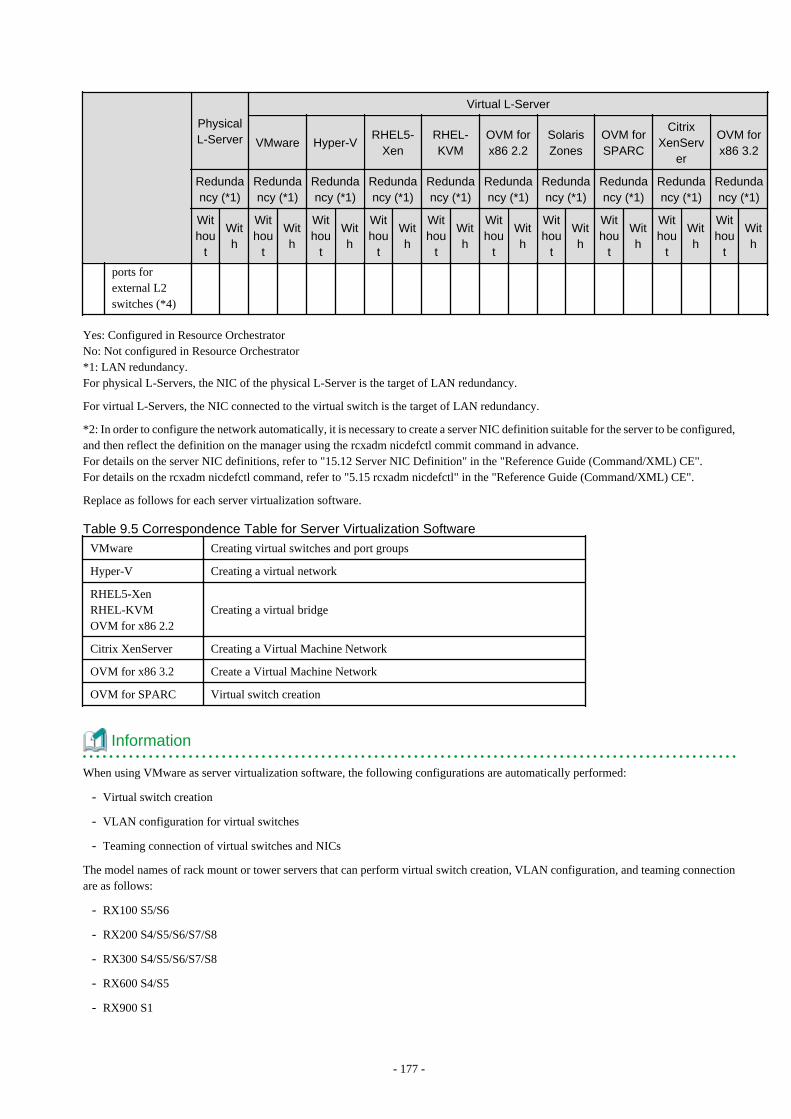
PhysicalL-Server
Virtual L-Server
VMware Hyper-VRHEL5-
XenRHEL-KVM
OVM forx86 2.2
SolarisZones
OVM forSPARC
CitrixXenServ
er
OVM forx86 3.2
Redundancy (*1)
Redundancy (*1)
Redundancy (*1)
Redundancy (*1)
Redundancy (*1)
Redundancy (*1)
Redundancy (*1)
Redundancy (*1)
Redundancy (*1)
Redundancy (*1)
Withou
t
With
Withou
t
With
Withou
t
With
Withou
t
With
Withou
t
With
Withou
t
With
Withou
t
With
Withou
t
With
Withou
t
With
Withou
t
With
ports forexternal L2switches (*4)
Yes: Configured in Resource OrchestratorNo: Not configured in Resource Orchestrator*1: LAN redundancy.For physical L-Servers, the NIC of the physical L-Server is the target of LAN redundancy.
For virtual L-Servers, the NIC connected to the virtual switch is the target of LAN redundancy.
*2: In order to configure the network automatically, it is necessary to create a server NIC definition suitable for the server to be configured,and then reflect the definition on the manager using the rcxadm nicdefctl commit command in advance.For details on the server NIC definitions, refer to "15.12 Server NIC Definition" in the "Reference Guide (Command/XML) CE".For details on the rcxadm nicdefctl command, refer to "5.15 rcxadm nicdefctl" in the "Reference Guide (Command/XML) CE".
Replace as follows for each server virtualization software.
Table 9.5 Correspondence Table for Server Virtualization Software
VMware Creating virtual switches and port groups
Hyper-V Creating a virtual network
RHEL5-XenRHEL-KVMOVM for x86 2.2
Creating a virtual bridge
Citrix XenServer Creating a Virtual Machine Network
OVM for x86 3.2 Create a Virtual Machine Network
OVM for SPARC Virtual switch creation
Information
When using VMware as server virtualization software, the following configurations are automatically performed:
- Virtual switch creation
- VLAN configuration for virtual switches
- Teaming connection of virtual switches and NICs
The model names of rack mount or tower servers that can perform virtual switch creation, VLAN configuration, and teaming connectionare as follows:
- RX100 S5/S6
- RX200 S4/S5/S6/S7/S8
- RX300 S4/S5/S6/S7/S8
- RX600 S4/S5
- RX900 S1
- 177 -

- TX150 S6/S7
- TX200 S5/S6
- TX300 S4/S5/S6
*3: Replace as follows for each server virtualization software.
Table 9.6 Correspondence Table for Server Virtualization Software
VMware Connections Virtual NICs of L-Servers and Port Groups of Virtual Switches
Hyper-V Connections Virtual NICs of L-Servers and Virtual Networks
RHEL5-XenRHEL-KVMOVM for x86 2.2
VLAN ID configuration for the L-Server virtual network interface andconnection with virtual bridges which have been created manually in advance
Solaris ZonesConnection of the L-Server virtual network interface with the host networkinterface
Citrix XenServerConnection of the L-Server virtual network interface with the network onXenServer
OVM for x86 3.2Connection of the L-Server virtual network interface with the virtual machinenetwork
OVM for SPARC Connection of the L-Server virtual network interface with the virtual switch
Information
If VMware is used as the server virtualization software and the same VLAN ID is used for the service console and port group, the portgroup and L-Server can be connected by creating a VMware excluded port group definition file.
See
For details on VMware excluded port group definition files, refer to "15.13 VMware Exclusion Port Group Definition File" in the"Reference Guide (Command/XML) CE".
*4: Configured by network device automatic configuration.
9.4.1.4 IP Address Auto-Configuration (Virtual L-Servers)[Physical Servers] [VMware] [Hyper-V] [KVM]If a subnet address has been set for the network resource, the IP address can be automatically set when deploying an image to an L-Server.The settings for the IP address, subnet mask, and default gateway are configured according to DHCP settings.
[Hyper-V]IP addresses can be automatically configured, on the following guest OSs on which the integrated services are installed.
- Microsoft(R) Windows Server(R) 2012
- Microsoft(R) Windows Server(R) 2008 R2
- Microsoft(R) Windows Server(R) 2008
- Microsoft(R) Windows Server(R) 2003 R2
- Microsoft(R) Windows Server(R) 2003
- Microsoft(R) Windows (R) 8
- Microsoft(R) Windows(R) 7
- 178 -
- Microsoft(R) Windows Vista(R)
- Microsoft(R) Windows(R) XP
[KVM]When the guest OS type is Linux, IP addresses can be automatically configured.
[Xen] [OVM for x86 2.2]Automatic configuration of IP addresses is not supported.
If a subnet address is set for a network resource, set an IP address manually after deploying an image to an L-Server (Also set an IP addressmanually on the DNS server).For details on how to check IP addresses, refer to the Note of "16.3.4 [Network] Tab" in the "User's Guide for Infrastructure Administrators(Resource Management) CE".
If no subnet address has been set, manually set a subnet address for operation on the DHCP server after deploying an image to an L-Server.
9.4.1.5 Automatic Configuration for L2 SwitchesWhen an L-Server or a network device (a firewall or server load balancer) is deployed on an L-Platform, definitions such as interfacescan be automatically configured on the L2 switch on the communication route, using a script created in advance.
9.4.1.6 Available Network ConfigurationsAvailable network configurations and configuration methods in Resource Orchestrator are given below.
PRIMERGY Blade Servers
- Non-Redundant Configuration
- For Physical L-Servers
Refer to "B.3.2 Manual Network Configuration" in the "Setup Guide CE".
- For Virtual L-Servers
Settings differ according to the server virtualization software being used.
[VMware]Refer to "C.2.5 Manual Network Configuration" in the "Setup Guide CE".
[Hyper-V]Refer to "C.3.5 Manual Network Configuration" in the "Setup Guide CE".
[Xen]Refer to "C.4.4 Manual Network Configuration" in the "Setup Guide CE".
[KVM]Refer to "C.6.4 Manual Network Configuration" in the "Setup Guide CE".
[OVM for x86 2.2]Refer to "C.5.4 Manual Network Configuration" in the "Setup Guide CE".
[Solaris Zones]Refer to "C.7.4 Manual Network Configuration" in the "Setup Guide CE".
[OVM for SPARC]Refer to "C.8.4 Manual Network Configuration" in the "Setup Guide CE".
[Citrix XenServer]Refer to "C.9.4 Manual Network Configuration" in the "Setup Guide CE".
[OVM for x86 3.2]Refer to "C.10.4 Manual Network Configuration" in the "Setup Guide CE".
- 179 -
- Redundant Configuration
- For Physical L-Servers
Refer to "B.3.1 Automatic Network Configuration" and "B.8 Network Redundancy and VLAN Settings of L-Servers" in the"Setup Guide CE".
- For Virtual L-Servers
Settings differ according to the server virtualization software being used.
[VMware]Refer to "C.2.4 Automatic Network Configuration" in the "Setup Guide CE".
[Hyper-V]Refer to "Automatic Network Configuration for Blade Servers" in "C.3.4 Automatic Network Configuration" in the "Setup GuideCE".
[Xen]Refer to "C.4.4 Manual Network Configuration" in the "Setup Guide CE".
[KVM]Refer to "C.6.4 Manual Network Configuration" in the "Setup Guide CE".
[OVM for x86 2.2]Refer to "C.5.4 Manual Network Configuration" in the "Setup Guide CE".
[Solaris Zones]Refer to "C.7.4 Manual Network Configuration" in the "Setup Guide CE".
[OVM for SPARC]Refer to "C.8.4 Manual Network Configuration" in the "Setup Guide CE".
[Citrix XenServer]Refer to "C.9.4 Manual Network Configuration" in the "Setup Guide CE".
[OVM for x86 3.2]Refer to "C.10.4 Manual Network Configuration" in the "Setup Guide CE".
PRIMERGY Rack Mount Servers, PRIMERGY Tower Servers, or PRIMEQUEST Servers
- Non-Redundant Configuration
- For Physical L-Servers
Refer to "B.3.2 Manual Network Configuration" in the "Setup Guide CE".
- For Virtual L-Servers
Settings differ according to the server virtualization software being used.
[VMware]Refer to "C.2.5 Manual Network Configuration" in the "Setup Guide CE".
[Hyper-V]Refer to "C.3.5 Manual Network Configuration" in the "Setup Guide CE".
[Xen]Refer to "C.4.4 Manual Network Configuration" in the "Setup Guide CE".
[KVM]Refer to "C.6.4 Manual Network Configuration" in the "Setup Guide CE".
[OVM for x86 2.2]Refer to "C.5.4 Manual Network Configuration" in the "Setup Guide CE".
[Solaris Zones]Refer to "C.7.4 Manual Network Configuration" in the "Setup Guide CE".
[OVM for SPARC]Refer to "C.8.4 Manual Network Configuration" in the "Setup Guide CE".
- 180 -
[Citrix XenServer]Refer to "C.9.4 Manual Network Configuration" in the "Setup Guide CE".
[OVM for x86 3.2]Refer to "C.10.4 Manual Network Configuration" in the "Setup Guide CE".
- Redundant Configuration
- For Physical L-Servers
Refer to "B.3.1 Automatic Network Configuration" in the "Setup Guide CE".
- For Virtual L-Servers
Settings differ according to the server virtualization software being used.
[VMware]Refer to "C.2.4 Automatic Network Configuration" in the "Setup Guide CE".
[Hyper-V]Refer to "C.3.5 Manual Network Configuration" in the "Setup Guide CE".
[Xen]Refer to "C.4.4 Manual Network Configuration" in the "Setup Guide CE".
[KVM]Refer to "C.6.4 Manual Network Configuration" in the "Setup Guide CE".
[OVM for x86 2.2]Refer to "C.5.4 Manual Network Configuration" in the "Setup Guide CE".
[Solaris Zones]Refer to "C.7.4 Manual Network Configuration" in the "Setup Guide CE".
[OVM for SPARC]Refer to "C.8.4 Manual Network Configuration" in the "Setup Guide CE".
[Citrix XenServer]Refer to "C.9.4 Manual Network Configuration" in the "Setup Guide CE".
[OVM for x86 3.2]Refer to "C.10.4 Manual Network Configuration" in the "Setup Guide CE".
Point
- When Creating Physical L-Servers
For details on the network configuration example, refer to "Appendix D Preparations for Creating a Physical L-Server".
- When Creating Virtual L-Servers
For details on the network configuration example, refer to "Appendix E Preparations for Creating a Virtual L-Server".
9.4.1.7 Network Settings for Physical L-ServersWhen configuring NIC redundancy and tagged VLANs, or specifying a Red Hat Enterprise Linux image, the network on the OS is notautomatically configured.Collect an image with the preset script that configures the network at initial OS startup, and then create an L-Server using that image.
Physical L-Server network information (such as IP address, NIC redundancy, and tagged VLAN settings) is transferred to the OS as anetwork information file when the image is deployed to the OS.For details on how to configure a network using a network information file, refer to "B.8 Network Redundancy and VLAN Settings of L-Servers" in the "Setup Guide CE".
When network configuration is not performed on the OS, create the L-Server then connect to it via the admin LAN or using the console,and configure the network on the OS on the L-Server.
- 181 -

Note
Depending on operating conditions of the network configuration script, a communication error may occur on the business application thatis installed on the server.
Since this error cannot be detected by Resource Orchestrator, please check any network errors that occur on user applications to detect it.
When those errors occur, the server or the application must be restarted.
Restart the server using the network configuration script.
9.4.1.8 Modifying Network Resource SpecificationsThe following network resource specifications can be modified.
- Basic information (network resource names, etc.)
- Connection information (LAN segments, etc.)
- Subnet information (subnet addresses, etc.)
For details on how to modify network specifications, refer to "7.5 Modifying Network Resource Specifications" in the "User's Guide forInfrastructure Administrators (Resource Management) CE", and "15.5.2 Modification" in the "Reference Guide (Command/XML) CE".
9.4.1.9 Automatic Network Configuration for Ethernet Fabric SwitchesWhen creating a network resource, a VLAN port profile is created for an Ethernet fabric switch with port profile configuration enabled.
Creating a VLAN port profile enables the port profile migration function (hereinafter AMPP) on the L-Server.
AMPP works with L-Server migration and automatically migrates the VLAN settings of the physical port of the Ethernet fabric switch tothe physical port of the Ethernet fabric switch adjacent to the migration target server.
- 182 -
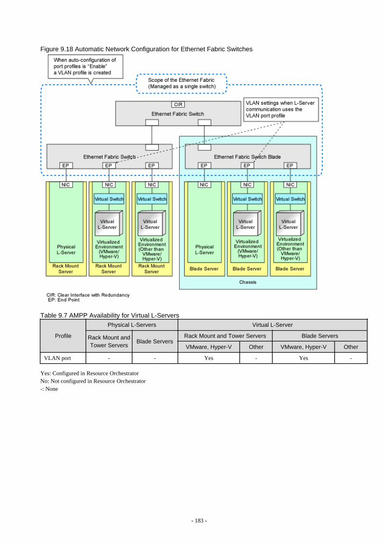
Figure 9.18 Automatic Network Configuration for Ethernet Fabric Switches
Table 9.7 AMPP Availability for Virtual L-Servers
Profile
Physical L-Servers Virtual L-Server
Rack Mount andTower Servers
Blade ServersRack Mount and Tower Servers Blade Servers
VMware, Hyper-V Other VMware, Hyper-V Other
VLAN port - - Yes - Yes -
Yes: Configured in Resource OrchestratorNo: Not configured in Resource Orchestrator-: None
- 183 -
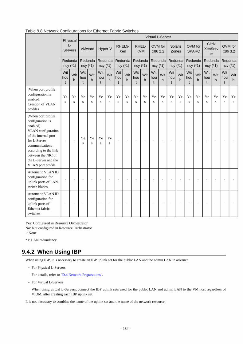
Table 9.8 Network Configurations for Ethernet Fabric Switches
PhysicalL-
Servers
Virtual L-Server
VMware Hyper-VRHEL5-
XenRHEL-KVM
OVM forx86 2.2
SolarisZones
OVM forSPARC
CitrixXenServ
er
OVM forx86 3.2
Redundancy (*1)
Redundancy (*1)
Redundancy (*1)
Redundancy (*1)
Redundancy (*1)
Redundancy (*1)
Redundancy (*1)
Redundancy (*1)
Redundancy (*1)
Redundancy (*1)
Withou
t
With
Withou
t
With
Withou
t
With
Withou
t
With
Withou
t
With
Withou
t
With
Withou
t
With
Withou
t
With
Withou
t
With
Withou
t
With
[When port profileconfiguration isenabled]Creation of VLANprofiles
Yes
Yes
Yes
Yes
Yes
Yes
Yes
Yes
Yes
Yes
Yes
Yes
Yes
Yes
Yes
Yes
Yes
Yes
Yes
Yes
[When port profileconfiguration isenabled]VLAN configurationof the internal portfor L-Servercommunicationsaccording to the linkbetween the NIC ofthe L-Server and theVLAN port profile
- -Yes
Yes
Yes
Yes
- - - - - - - - - - - - - -
Automatic VLAN IDconfiguration foruplink ports of LANswitch blades
- - - - - - - - - - - - - - - - - - - -
Automatic VLAN IDconfiguration foruplink ports ofEthernet fabricswitches
- - - - - - - - - - - - - - - - - - - -
Yes: Configured in Resource OrchestratorNo: Not configured in Resource Orchestrator-: None
*1: LAN redundancy.
9.4.2 When Using IBPWhen using IBP, it is necessary to create an IBP uplink set for the public LAN and the admin LAN in advance.
- For Physical L-Servers
For details, refer to "D.4 Network Preparations".
- For Virtual L-Servers
When using virtual L-Servers, connect the IBP uplink sets used for the public LAN and admin LAN to the VM host regardless ofVIOM, after creating each IBP uplink set.
It is not necessary to combine the name of the uplink set and the name of the network resource.
- 184 -
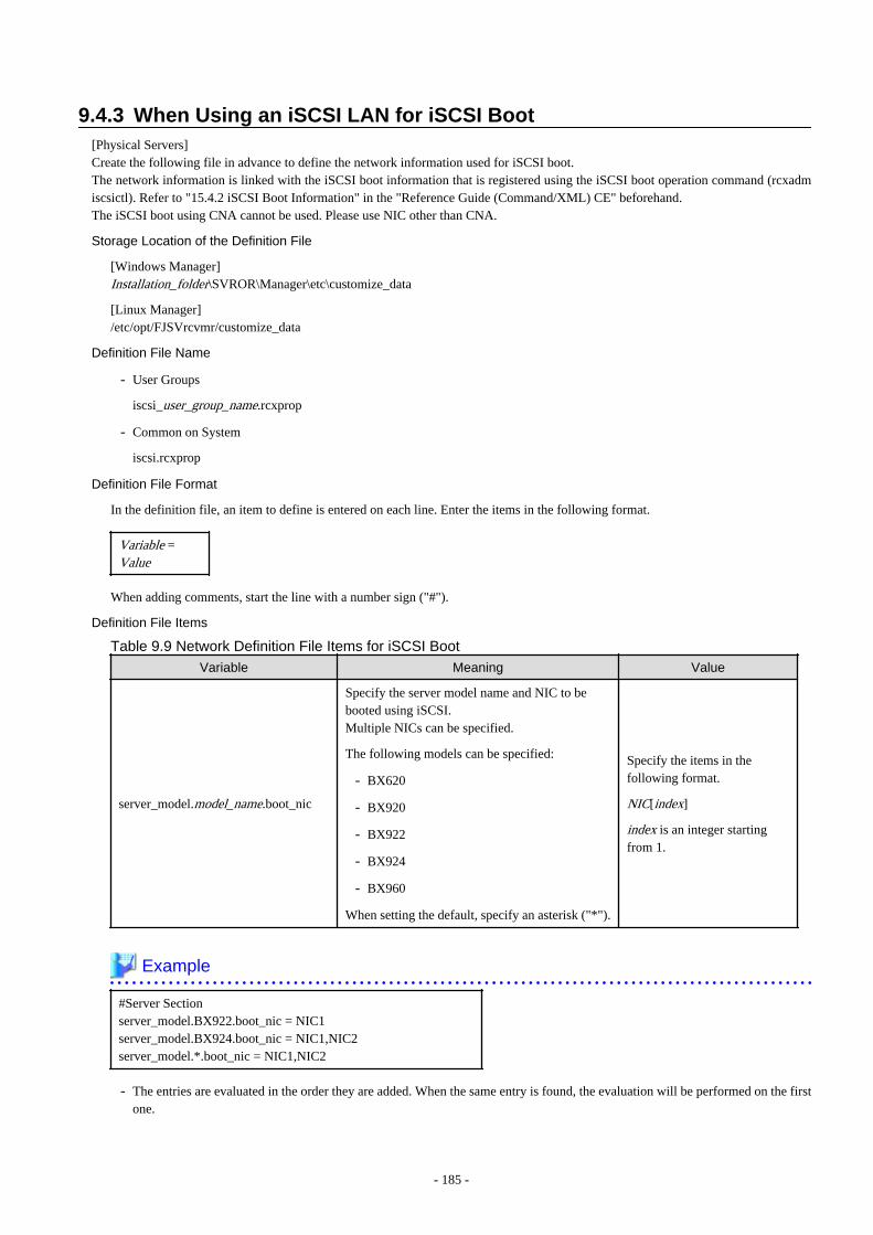
9.4.3 When Using an iSCSI LAN for iSCSI Boot[Physical Servers]Create the following file in advance to define the network information used for iSCSI boot.The network information is linked with the iSCSI boot information that is registered using the iSCSI boot operation command (rcxadmiscsictl). Refer to "15.4.2 iSCSI Boot Information" in the "Reference Guide (Command/XML) CE" beforehand.The iSCSI boot using CNA cannot be used. Please use NIC other than CNA.
Storage Location of the Definition File
[Windows Manager]Installation_folder\SVROR\Manager\etc\customize_data
[Linux Manager]/etc/opt/FJSVrcvmr/customize_data
Definition File Name
- User Groups
iscsi_user_group_name.rcxprop
- Common on System
iscsi.rcxprop
Definition File Format
In the definition file, an item to define is entered on each line. Enter the items in the following format.
Variable =Value
When adding comments, start the line with a number sign ("#").
Definition File Items Table 9.9 Network Definition File Items for iSCSI Boot
Variable Meaning Value
server_model.model_name.boot_nic
Specify the server model name and NIC to bebooted using iSCSI.Multiple NICs can be specified.
The following models can be specified:
- BX620
- BX920
- BX922
- BX924
- BX960
When setting the default, specify an asterisk ("*").
Specify the items in thefollowing format.
NIC[index]
index is an integer startingfrom 1.
Example
#Server Sectionserver_model.BX922.boot_nic = NIC1server_model.BX924.boot_nic = NIC1,NIC2server_model.*.boot_nic = NIC1,NIC2
- The entries are evaluated in the order they are added. When the same entry is found, the evaluation will be performed on the firstone.
- 185 -
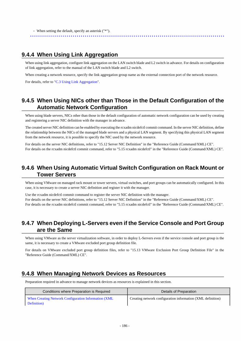
- When setting the default, specify an asterisk ("*").
9.4.4 When Using Link AggregationWhen using link aggregation, configure link aggregation on the LAN switch blade and L2 switch in advance. For details on configurationof link aggregation, refer to the manual of the LAN switch blade and L2 switch.
When creating a network resource, specify the link aggregation group name as the external connection port of the network resource.
For details, refer to "C.3 Using Link Aggregation".
9.4.5 When Using NICs other than Those in the Default Configuration of theAutomatic Network Configuration
When using blade servers, NICs other than those in the default configuration of automatic network configuration can be used by creatingand registering a server NIC definition with the manager in advance.
The created server NIC definition can be enabled by executing the rcxadm nicdefctl commit command. In the server NIC definition, definethe relationship between the NICs of the managed blade servers and a physical LAN segment. By specifying this physical LAN segmentfrom the network resource, it is possible to specify the NIC used by the network resource.
For details on the server NIC definitions, refer to "15.12 Server NIC Definition" in the "Reference Guide (Command/XML) CE".For details on the rcxadm nicdefctl commit command, refer to "5.15 rcxadm nicdefctl" in the "Reference Guide (Command/XML) CE".
9.4.6 When Using Automatic Virtual Switch Configuration on Rack Mount orTower Servers
When using VMware on managed rack mount or tower servers, virtual switches, and port groups can be automatically configured. In thiscase, it is necessary to create a server NIC definition and register it with the manager.
Use the rcxadm nicdefctl commit command to register the server NIC definition with the manager.For details on the server NIC definitions, refer to "15.12 Server NIC Definition" in the "Reference Guide (Command/XML) CE".For details on the rcxadm nicdefctl commit command, refer to "5.15 rcxadm nicdefctl" in the "Reference Guide (Command/XML) CE".
9.4.7 When Deploying L-Servers even if the Service Console and Port Groupare the Same
When using VMware as the server virtualization software, in order to deploy L-Servers even if the service console and port group is thesame, it is necessary to create a VMware excluded port group definition file.
For details on VMware excluded port group definition files, refer to "15.13 VMware Exclusion Port Group Definition File" in the"Reference Guide (Command/XML) CE".
9.4.8 When Managing Network Devices as ResourcesPreparation required in advance to manage network devices as resources is explained in this section.
Conditions where Preparation is Required Details of Preparation
When Creating Network Configuration Information (XMLDefinition)
Creating network configuration information (XML definition)
- 186 -
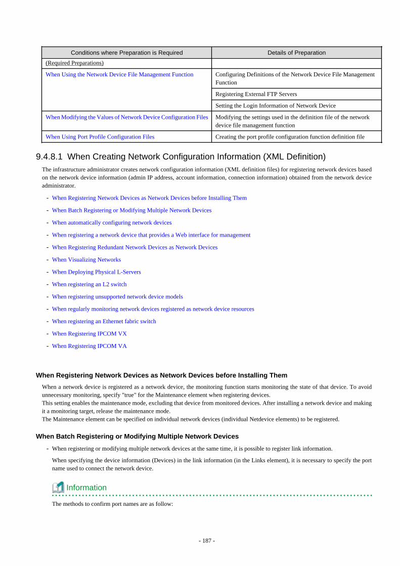
Conditions where Preparation is Required Details of Preparation
(Required Preparations)
When Using the Network Device File Management Function Configuring Definitions of the Network Device File ManagementFunction
Registering External FTP Servers
Setting the Login Information of Network Device
When Modifying the Values of Network Device Configuration Files Modifying the settings used in the definition file of the networkdevice file management function
When Using Port Profile Configuration Files Creating the port profile configuration function definition file
9.4.8.1 When Creating Network Configuration Information (XML Definition)The infrastructure administrator creates network configuration information (XML definition files) for registering network devices basedon the network device information (admin IP address, account information, connection information) obtained from the network deviceadministrator.
- When Registering Network Devices as Network Devices before Installing Them
- When Batch Registering or Modifying Multiple Network Devices
- When automatically configuring network devices
- When registering a network device that provides a Web interface for management
- When Registering Redundant Network Devices as Network Devices
- When Visualizing Networks
- When Deploying Physical L-Servers
- When registering an L2 switch
- When registering unsupported network device models
- When regularly monitoring network devices registered as network device resources
- When registering an Ethernet fabric switch
- When Registering IPCOM VX
- When Registering IPCOM VA
When Registering Network Devices as Network Devices before Installing Them
When a network device is registered as a network device, the monitoring function starts monitoring the state of that device. To avoidunnecessary monitoring, specify "true" for the Maintenance element when registering devices.This setting enables the maintenance mode, excluding that device from monitored devices. After installing a network device and makingit a monitoring target, release the maintenance mode.The Maintenance element can be specified on individual network devices (individual Netdevice elements) to be registered.
When Batch Registering or Modifying Multiple Network Devices
- When registering or modifying multiple network devices at the same time, it is possible to register link information.
When specifying the device information (Devices) in the link information (in the Links element), it is necessary to specify the portname used to connect the network device.
Information
The methods to confirm port names are as follow:
- 187 -
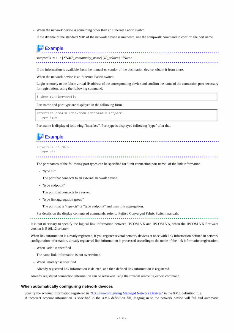
- When the network device is something other than an Ethernet Fabric switch
If the ifName of the standard MIB of the network device is unknown, use the snmpwalk command to confirm the port name.
Example
snmpwalk -v 1 -c [SNMP_community_name] [IP_address] ifName
If the information is available from the manual or vendor of the destination device, obtain it from there.
- When the network device is an Ethernet Fabric switch
Login remotely to the fabric virtual IP address of the corresponding device and confirm the name of the connection port necessaryfor registration, using the following command:
# show running-config
Port name and port type are displayed in the following form.
interface domain_id/switch_id/chassis_id/port type type
Port name is displayed following "interface". Port type is displayed following "type" after that.
Example
interface 3/1/0/3 type cir
The port names of the following port types can be specified for "unit connection port name" of the link information.
- "type cir"
The port that connects to an external network device.
- "type endpoint"
The port that connects to a server.
- "type linkaggregation group"
The port that is "type cir" or "type endpoint" and uses link aggregation.
For details on the display contents of commands, refer to Fujitsu Converged Fabric Switch manuals.
- It is not necessary to specify the logical link information between IPCOM VX and IPCOM VA, when the IPCOM VX firmwareversion is E10L12 or later.
- When link information is already registered, if you register several network devices at once with link information defined in networkconfiguration information, already registered link information is processed according to the mode of the link information registration.
- When "add" is specified
The same link information is not overwritten.
- When "modify" is specified
Already registered link information is deleted, and then defined link information is registered.
Already registered connection information can be retrieved using the rcxadm netconfig export command.
When automatically configuring network devices
Specify the account information registered in "9.3.3 Pre-configuring Managed Network Devices" in the XML definition file.If incorrect account information is specified in the XML definition file, logging in to the network device will fail and automatic
- 188 -
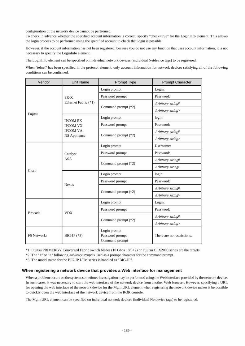
configuration of the network device cannot be performed.To check in advance whether the specified account information is correct, specify "check=true" for the LoginInfo element. This allowsthe login process to be performed using the specified account to check that login is possible.
However, if the account information has not been registered, because you do not use any function that uses account information, it is notnecessary to specify the LoginInfo element.
The LoginInfo element can be specified on individual network devices (individual Netdevice tags) to be registered.
When "telnet" has been specified in the protocol element, only account information for network devices satisfying all of the followingconditions can be confirmed.
Vendor Unit Name Prompt Type Prompt Character
Fujitsu
SR-XEthernet Fabric (*1)
Login prompt Login:
Password prompt Password:
Command prompt (*2)Arbitrary string#
Arbitrary string>
IPCOM EXIPCOM VXIPCOM VANS Appliance
Login prompt login:
Password prompt Password:
Command prompt (*2)Arbitrary string#
Arbitrary string>
Cisco
CatalystASA
Login prompt Username:
Password prompt Password:
Command prompt (*2)Arbitrary string#
Arbitrary string>
Nexus
Login prompt login:
Password prompt Password:
Command prompt (*2)Arbitrary string#
Arbitrary string>
Brocade VDX
Login prompt Login:
Password prompt Password:
Command prompt (*2)Arbitrary string#
Arbitrary string>
F5 Networks BIG-IP (*3)Login promptPassword promptCommand prompt
There are no restrictions.
*1: Fujitsu PRIMERGY Converged Fabric switch blades (10 Gbps 18/8+2) or Fujitsu CFX2000 series are the targets.*2: The "#" or ">" following arbitrary string is used as a prompt character for the command prompt.*3: The model name for the BIG-IP LTM series is handled as "BIG-IP".
When registering a network device that provides a Web interface for management
When a problem occurs on the system, sometimes investigation may be performed using the Web interface provided by the network device.In such cases, it was necessary to start the web interface of the network device from another Web browser. However, specifying a URLfor opening the web interface of the network device for the MgmtURL element when registering the network device makes it be possibleto quickly open the web interface of the network device from the ROR console.
The MgmtURL element can be specified on individual network devices (individual Netdevice tags) to be registered.
- 189 -
When Registering Redundant Network Devices as Network Devices
Network devices that have the same "vendor name" and "device name" can be registered for redundant configurations. When registeringa network device that has the same vendor name and device name, specify the same value as the registered network device for "Group_ID"of the Redundancy group_id element to treat that device as being in a redundant configuration.
For the "vendor name" and "device name" of a network device, collect MIB information from the network device when registering it, andconfirm that the "vendor name" and "device name" are same as the ones of the registered device.
When Visualizing Networks
Register following network link information enables visualization of their connection relationships.
- Link information between two network devices
- Link information between network devices and LAN switch blades
- Link information between network devices and rack mount servers or tower servers
For details on visualization of networks, refer to "Chapter 11 NetworkViewer" in the "User's Guide for Infrastructure Administrators(Resource Management) CE".
For details on how to specify link information, refer to "15.6.1 Creation" in the "Reference Guide (Command/XML) CE".
When Deploying Physical L-Servers
In order to perform automatic configuration of network devices when deploying physical L-servers, it is necessary to register theinformation about links between the network devices and the rack mount or tower servers.
- Register all link information of the admin LAN and public LANs connected to the rack mount servers or tower servers.
- It is necessary to align the NIC number of the rack mount server or tower server with the subscript of the interface name of the serverOS in advance. Also, use NIC1 and NIC2 (for redundancy) for the admin LAN.As NIC numbers used for the public LAN are 3 or a higher number, be careful when specifying connection information.
Example
[Windows]NIC number = the subscript of the OS interface name
The first NIC: Local Area ConnectionThe second NIC: Local Area Connection 2
[Linux]NIC number -1 = the subscript of the OS interface name
The first NIC: eth0The second NIC: eth1
For details on how to specify link information, refer to "15.6.1 Creation" in the "Reference Guide (Command/XML) CE".
When registering an L2 switch
When registering an L2 switch as a network device, omit the Tenant element.
When registering unsupported network device models
Add the model of the network device to be registered to the model definition for network devices, and register the network device afterupdating the model definition file.
When regularly monitoring network devices registered as network device resources
When the workload of the network or network devices is temporarily increased, the response to the communication of regular monitoringmay be delayed. When this delay exceeds the time-out period, the communication for regular monitoring will be executed again.
- 190 -
Therefore, if the monitoring interval (Interval element) or timeout period (Timeout element) specified during registration is short, thenumber of communications for regular monitoring may increase. It is recommended to use the default values in order to avoid increasingthe load on the network and network devices.
When registering an Ethernet fabric switch
- About Virtual Fabrics (VFAB)
When managing virtual fabrics using Resource Orchestrator, it is necessary to define the virtual fabric information in the Vfab elementof the network configuration information.
- Usage form of virtual fabrics
Virtual fabrics can be used in the following two forms using Resource Orchestrator:
- Use pre-configured virtual fabrics.
- Auto-configuration of virtual fabrics.
- When using pre-configured virtual fabrics
Specify "false" for the vfabauto attribute of the Vfab element, and specify pre-configured information for the other definitionsunder the Vfab element.Do not specify values for the Dot1adPorts element or the CirPorts element.
- When configuring virtual fabrics automatically
Specify "true" for the vfabauto attribute of the Vfab element, and specify the information to automatically configure for the otherdefinitions under the Vfab element.When configuring a virtual fabric in host mode, the CIR for the virtual fabric can be automatically configured by specifying aCIR port in the CirPort element.For details, refer to "H.1.3 Virtual Fabrics".
When connecting with IPCOM VX, IEEE802.1ad frame communication ports can be automatically configured by specifying aport to connect with the IPCOM VX in the Dot1adPort element.
- Relationship with tenants
In Resource Orchestrator, virtual fabrics are handled as being related to tenants.By allocating a virtual fabric for each tenant, it is possible to provide an independent VLAN space for each tenant.To associate a virtual fabric with a tenant, specify the tenant name in the Tenant element of the Vfab tag.For details on the relationship between tenants and virtual fabrics, refer to "H.1.3 Virtual Fabrics".
- About Operation of Virtual Fabrics (VFAB)
Specify the Vfab element so the number of operated VFABs does not exceed the limit (100).Operated VFABs differ depending on the value specified for the VFAB registration mode (the Mode element) as follows.
- When the VFAB registration mode is omitted or set to "replace"
The sum of the number of Vfab elements included in the network configuration information and the number of registeredVFABs not corresponding to the VFAB ID attributes of such Vfab elements (VFABs to be deleted)
- When the VFAB registration mode is set to "add", "modify", or "delete"
The number of Vfab elements included in the network configuration information
Note
When modifying the modification information of the domain switch in an Ethernet Fabric switch registered as the network devicein Resource Orchestrator, reflect the modified information on Resource Orchestrator.
For details on how to reflect the modified information, refer to "9.5.3.4 Reflecting a Modified Domain Switch Configuration onthe Ethernet Fabric" in the "Operation Guide CE".
- 191 -
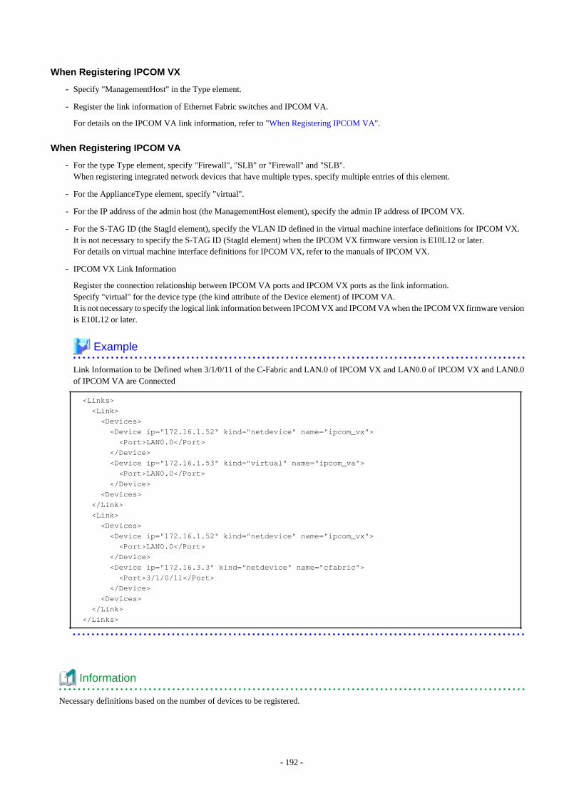
When Registering IPCOM VX
- Specify "ManagementHost" in the Type element.
- Register the link information of Ethernet Fabric switches and IPCOM VA.
For details on the IPCOM VA link information, refer to "When Registering IPCOM VA".
When Registering IPCOM VA
- For the type Type element, specify "Firewall", "SLB" or "Firewall" and "SLB".When registering integrated network devices that have multiple types, specify multiple entries of this element.
- For the ApplianceType element, specify "virtual".
- For the IP address of the admin host (the ManagementHost element), specify the admin IP address of IPCOM VX.
- For the S-TAG ID (the StagId element), specify the VLAN ID defined in the virtual machine interface definitions for IPCOM VX.It is not necessary to specify the S-TAG ID (StagId element) when the IPCOM VX firmware version is E10L12 or later.For details on virtual machine interface definitions for IPCOM VX, refer to the manuals of IPCOM VX.
- IPCOM VX Link Information
Register the connection relationship between IPCOM VA ports and IPCOM VX ports as the link information.Specify "virtual" for the device type (the kind attribute of the Device element) of IPCOM VA.It is not necessary to specify the logical link information between IPCOM VX and IPCOM VA when the IPCOM VX firmware versionis E10L12 or later.
Example
Link Information to be Defined when 3/1/0/11 of the C-Fabric and LAN.0 of IPCOM VX and LAN0.0 of IPCOM VX and LAN0.0of IPCOM VA are Connected
<Links> <Link> <Devices> <Device ip="172.16.1.52" kind="netdevice" name="ipcom_vx"> <Port>LAN0.0</Port> </Device> <Device ip="172.16.1.53" kind="virtual" name="ipcom_va"> <Port>LAN0.0</Port> </Device> <Devices> </Link> <Link> <Devices> <Device ip="172.16.1.52" kind="netdevice" name="ipcom_vx"> <Port>LAN0.0</Port> </Device> <Device ip="172.16.3.3" kind="netdevice" name="cfabric"> <Port>3/1/0/11</Port> </Device> <Devices> </Link> </Links>
Information
Necessary definitions based on the number of devices to be registered.
- 192 -
- When registering each network device individually
The Netdevice element must be the first.
- When registering all network devices at once
Starting with the Netconfig element, define the settings for each network device under the Netdevices element.When registering multiple network devices at once, connection information can be also defined under the Links element.
See
- For details on network configuration information (XML definitions), refer to "15.6 Network Configuration Information" in the"Reference Guide (Command/XML) CE".
- For details on the rcxadm netconfig command, refer to "3.7 rcxadm netconfig" in the "Reference Guide (Command/XML) CE".
- For details on releasing maintenance mode, refer to "22.1 Switchover of Maintenance Mode" in the "User's Guide for InfrastructureAdministrators (Resource Management) CE".
- For details on model definitions for network devices, refer to "15.14 Network Device Model Definition" in the "Reference Guide(Command/XML) CE".
9.4.8.2 When Using the Network Device File Management FunctionThe preparation necessary to use the network device file management function is explained in this section.
Information
When the Ethernet fabric is comprised of "Fujitsu PRIMERGY Converged Fabric Switch Blade (10 Gps 18/8+2)" and "Fujitsu ConvergedFabric Switch ", the network device file management function is not used. Follow the maintenance procedure of the corresponding device.Follow the maintenance procedure of the corresponding device.
Configuring Definitions of the Network Device File Management Function
When using the network device file management function, it is necessary to configure the functions to be used and the number of generationfiles in the definition file in advance.
When details on how to define the network device file management function, refer to "9.4.8.3 When Modifying the Values of NetworkDevice Configuration Files".
Registering External FTP Servers
When managing network device files, for network devices without an FTP server function, an external FTP server is necessary.
- Backup the network device file
- Transfer the backed up network device file to the admin server the manager is operating on
- Transfer the backed up network device file from the admin server the manager is operating on
- Restore the network device file transferred from the admin server to the target network device
Execute the rcxadm netconfig import command and register an external ftp server.
For details on the rcxadm netconfig command, refer to "3.7 rcxadm netconfig" in the "Reference Guide (Command/XML) CE".
Point
When using a Nexus 5000 series, it is necessary to set the following settings for external ftp server in advance to enable backup andrestoration of network device files.
1. Set the change root.
- 193 -
2. Change the root directory("/") of the account to the home directory.
Setting the Login Information of Network Device
When registering or changing network devices, register the login information in the network configuration information (XML definition).
- For the "SR-X series"
- LoginInfo protocol: ftp
- User: Must be specified
- Password: Must be specified
- Tenant: Do not specify
- For the "BIG-IP Local Traffic Manager series"
- LoginInfo protocol: ssh
- LoginInfo authority: admin
- User: Must be specified
- Password: Must be specified
- Tenant: Do not specify
- For the "Nexus 5000 series"
- LoginInfo protocol: telnet or ssh
- LoginInfo authority: admin
- User: Must be specified
- Password: Must be specified
- Tenant: Do not specify
- For other supported devices
- LoginInfo protocol: telnet or ssh
- LoginInfo authority: user
- User: Must be specified
- Password: Must be specified
- PrivilegedPassword: Must be specified
- Tenant: Do not specify
Note
This section explains points to keep in mind when using this function.
- When using an "IPCOM EX series" or an "IPCOM VA series"
- This function creates a temporary file in the network device.Do not create the following files in the network device.
- ror-running-config.cli
- ror-startup-config.cli
Also, secure sufficient disk space to save the network device configuration file on the network device itself.
- 194 -
- When restoring the network device file without initializing the authentication information
Execute the rcxadm netdevice cfexport command and export the network device environment file in advance, and then configureIPCOM EX or IPCOM VA manually.For details on configuration, refer to the IPCOM EX or IPCOM VA manuals.
- When deleting, changing, or deleting the account information registered in this product
Execute the rcxadm netdevice cfbackup command and backup the network device configuration file.If restoration is performed without backing up, the restoration may fail due to account information inconsistency.
- When using the automatic updating function for authentication information
When executing the rcxadm netdevice cfrestore command and restoring the network device environment file, authenticationinformation may be initialized.
Example
Functions that are automatically updated include the following.
- When "skey" in account authentication type is specified
- When the authentication in SSL-VPN client or L2TP/IPsec client is performed using "local database operation"
- When using a "BIG-IP Local Traffic Manager series"
- The user specified in login information must operate the network device using tmsh immediately after login.
- This function creates a temporary file in the network device.Do not create the following files in the network device.
- /var/local/ucs/environment.ucs
- /var/local/scf/config.scf
Also, secure sufficient disk space to save the network device file on the network device.
- When using a "Nexus 5000 series"
- When restoring a "Nexus 5000 series", perform the following.
- When not connecting a "Nexus 2000 series"
(1) Log in to the target Nexus, and confirm the management IP address and SNMP community name.(2) Clear startup-config using the write erase command.(3) Restart the target Nexus.(4) After restarting, log in to the target Nexus again.(5) Set the management IP address and SNMP community name which were confirmed in (1).(6) After log out of the target Nexus, and perform to restoration.
- When connecting a "Nexus 2000 series"
(1) Log in to the target Nexus, and confirm the management IP address and SNMP community name.(2) Clear startup-config using the write erase command.(3) Restart the target Nexus.(4) After restarting, log in to the target Nexus again.(5) Set the FEX.(6) Set the management IP address and SNMP community name which were confirmed in (1).(7) After log out of the target Nexus, and perform to restoration.
- When using a "Cisco ASA 5500 series"
When using redundancy configurations and only one device is faulty, it is not necessary to execute the rcxadm netdevice cfrestorecommand.Using the functions of the "Cisco ASA 5500 series", the configuration of the active device can be reflected automatically.For details, refer to the "Cisco ASA 5500 series" manuals.
- 195 -

- When using a "Catalyst series"
This function creates a temporary file in the network device.Do not create the following files in the network device.
- flash:ror-running-config
Also, secure sufficient disk space to save the network device configuration file on the network device itself.
9.4.8.3 When Modifying the Values of Network Device Configuration FilesThe definition of the configuration management of the network device can be changed by setting the value to the following definition filesbeforehand.
Storage Location of the Definition File
[Windows Manager]Installation_folder\SVROR\Manager\etc\customize_data
[Linux Manager]/etc/opt/FJSVrcvmr/customize_data
Definition File Name
unm_mon.rcxprop
Definition File Format
Specify variables in the definition file in the following format.
Parameter =Value
Parameter
Specify variables for network device configuration file management.
Parameter Meaning and Value
CONFIG_BACKUP Specify whether to enable the network device file backup function.
- true
Network device file backup is enabled.
- false
Network device file backup is disabled.
If left blank, "true" is set.
CONFIG_AUTO_MASTER Specify whether to collect a master configuration file when registering a network deviceas a resource.
- true
A master configuration file is collected.
- false
A master configuration file is not collected.
If left blank, "false" is set.
CONFIG_AUTO_BACKUP Specify whether to back up configuration files when network device auto-configurationis performed.
- true
Network device configuration file backup is performed.
- false
- 196 -
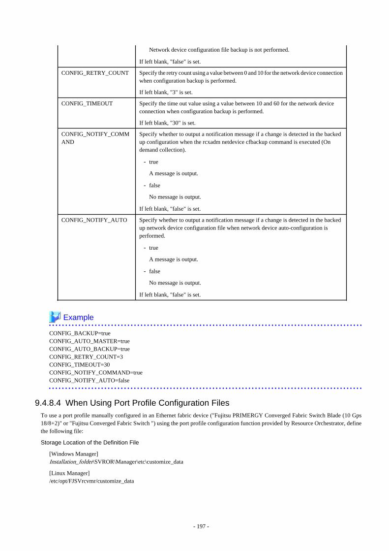
Network device configuration file backup is not performed.
If left blank, "false" is set.
CONFIG_RETRY_COUNT Specify the retry count using a value between 0 and 10 for the network device connectionwhen configuration backup is performed.
If left blank, "3" is set.
CONFIG_TIMEOUT Specify the time out value using a value between 10 and 60 for the network deviceconnection when configuration backup is performed.
If left blank, "30" is set.
CONFIG_NOTIFY_COMMAND
Specify whether to output a notification message if a change is detected in the backedup configuration when the rcxadm netdevice cfbackup command is executed (Ondemand collection).
- true
A message is output.
- false
No message is output.
If left blank, "false" is set.
CONFIG_NOTIFY_AUTO Specify whether to output a notification message if a change is detected in the backedup network device configuration file when network device auto-configuration isperformed.
- true
A message is output.
- false
No message is output.
If left blank, "false" is set.
Example
CONFIG_BACKUP=trueCONFIG_AUTO_MASTER=trueCONFIG_AUTO_BACKUP=trueCONFIG_RETRY_COUNT=3CONFIG_TIMEOUT=30CONFIG_NOTIFY_COMMAND=trueCONFIG_NOTIFY_AUTO=false
9.4.8.4 When Using Port Profile Configuration FilesTo use a port profile manually configured in an Ethernet fabric device ("Fujitsu PRIMERGY Converged Fabric Switch Blade (10 Gps18/8+2)" or "Fujitsu Converged Fabric Switch ") using the port profile configuration function provided by Resource Orchestrator, definethe following file:
Storage Location of the Definition File
[Windows Manager]Installation_folder\SVROR\Manager\etc\customize_data
[Linux Manager]/etc/opt/FJSVrcvmr/customize_data
- 197 -
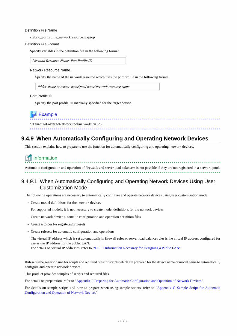
Definition File Name
cfabric_portprofile_networkresource.rcxprop
Definition File Format
Specify variables in the definition file in the following format.
Network Resource Name=Port Profile ID
Network Resource Name
Specify the name of the network resource which uses the port profile in the following format:
folder_name or tenant_name/pool name/network resource name
Port Profile ID
Specify the port profile ID manually specified for the target device.
Example
"/TenantA/FolderA/NetworkPool/network1"=123
9.4.9 When Automatically Configuring and Operating Network DevicesThis section explains how to prepare to use the function for automatically configuring and operating network devices.
Information
Automatic configuration and operation of firewalls and server load balancers is not possible if they are not registered in a network pool.
9.4.9.1 When Automatically Configuring and Operating Network Devices Using UserCustomization Mode
The following operations are necessary to automatically configure and operate network devices using user customization mode.
- Create model definitions for the network devices
For supported models, it is not necessary to create model definitions for the network devices.
- Create network device automatic configuration and operation definition files
- Create a folder for registering rulesets
- Create rulesets for automatic configuration and operations
The virtual IP address which is set automatically in firewall rules or server load balance rules is the virtual IP address configured foruse as the IP address for the public LAN.For details on virtual IP addresses, refer to "9.1.3.1 Information Necessary for Designing a Public LAN".
Ruleset is the generic name for scripts and required files for scripts which are prepared for the device name or model name to automaticallyconfigure and operate network devices.
This product provides samples of scripts and required files.
For details on preparation, refer to "Appendix F Preparing for Automatic Configuration and Operation of Network Devices".
For details on sample scripts and how to prepare when using sample scripts, refer to "Appendix G Sample Script for AutomaticConfiguration and Operation of Network Devices".
- 198 -

9.4.9.2 When Automatically Configuring and Operating Network Devices Using SimpleConfiguration Mode
The following operations are necessary to automatically configure and operate network devices using simple configuration mode.
- Creating Interface Configuration Files
For details on pre-configuration, refer to "Appendix I Auto-configuration and Operations of Network Devices Using Simple ConfigurationMode".
9.5 When Providing an IPv6 Network for Public LANsWhen building an IPv6 network on a public LAN, the required network devices and settings vary depending on the desired operations.
Note
- Resource Orchestrator does not provide IPv6 address management.
Address management should be performed by the infrastructure administrator and tenant administrator.
- Network configurations that allow IPv6 packets on a public LAN to pass through the admin LAN to reach the admin server andmanaged server or units are not supported.
Table 9.10 Network Devices Required for an IPv6 Network on a Public LAN
OperationRequired Network
DeviceRequired Configuration
Use of a static IP address to allow access fromother servers.
None Configure an IPv6 address for the server OS.
Connects with the other servers as a client.IP addresses are configured by the server'sautomatic configuration function.
IPv6 routers Set a prefix and the RA M/O flag on the IPv6 router.
Use of the name published using DNS toallow access from the other servers.IP addresses are configured by the server'sautomatic configuration function.
IPv6 routers Set a prefix and the RA M/O flag on the IPv6 router.
DHCPv6 server Register the DNS address on the DHCPv6 server.
DNS server
Configure the DNS server to enable connection with theIPv6 network.
Configure the IPv6 address assigned to the server anddomain name to be published on the DNS server.
Use of the name published using DNS toallow access from the other servers.Static IP addresses are assigned using aDHCPv6 server.
IPv6 routers Set a prefix and the RA M/O flag on the IPv6 router.
DHCPv6 server
Register the DNS address on the DHCPv6 server.
Add an entry for the server identifier (DUID) and entriesincluding the pair of the NIC identifier (IAID) and theIPv6 address to the DHCPv6 server.
DNS server
Configure the DNS server to enable connection with theIPv6 network.
Configure the IPv6 address assigned to the server anddomain name to be published on the DNS server.
* Note: When the IP address changes because of automatic IP address configuration performed by the server, the server may be temporarilyinaccessible until updating processes for DNS cache, etc. complete. To avoid such a problem, use an automatic IP address configurationmethod that would not change IP addresses over time (such as EUI-64 or the OS specific method).
- 199 -

Information
- In order to use IPv6 immediately after image deployment, perform the following on the collection target OS before collecting theimage:
- Enable IPv6
- When there are manually configured IPv6 addresses, delete them
- In Resource Orchestrator, an IPv6 network can be used for the public LAN only when using the following L-Servers:
- Physical L-Servers
- Virtual L-Servers (only for VMware)
For details on required configurations for individual devices, refer to the manual of each device.
Design of IPv6 Prefixes to be Allocated to Public LANs
An example of designing the IPv6 address range (prefix and network ID) to be allocated to each public LAN based on the assigned GUAis given below:
Assign prefixes in the unit of /64 for each network t so that automatic server configuration can be selected.
For three-tier models, assign /62 for the prefix length of each L-Platform, as this model requires four networks (three "public LAN networks"and one "network connecting IPv4/v6 routers and firewalls").
When performing static routing, configure routing settings on the IPv6 router. For details on how to configure routing on the IPv6 router,refer to the manual for the IPv6 router being used.
- 200 -
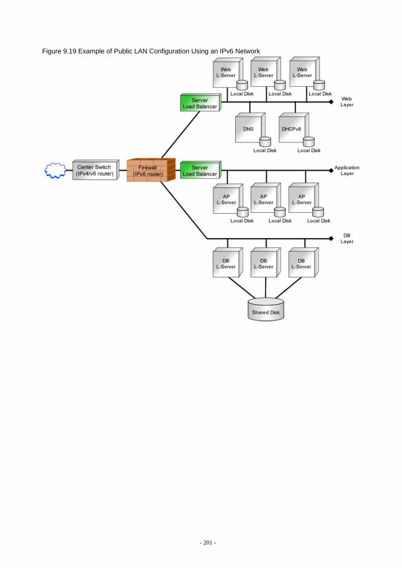
Figure 9.19 Example of Public LAN Configuration Using an IPv6 Network
- 201 -
Chapter 10 Deciding and Configuring the StorageEnvironment
This section explains how to define and configure the storage environment.
10.1 Deciding the Storage EnvironmentThis section explains how to define the storage environment settings required for a Resource Orchestrator setup.
10.1.1 Allocating StorageWhen preparing physical servers and virtual machines, it was difficult to smoothly provide servers as the configuration of storage unitsand the storage network was necessary.
Using the following functions of Resource Orchestrator, servers can be provided smoothly.
Allocating Storage to a Virtual L-Server
There are two ways to allocate storage to a virtual L-Server:
- Allocate disk resources (virtual disks) automatically created from virtual storage resources (datastores) [VMware] [Hyper-V] [OVMfor x86] [Xen] [KVM]
- Allocate disk resources (raw devices or partitions) that were created in advance [KVM] [Solaris Zones] [OVM for SPARC]
Allocate disk resources (virtual disks) automatically created from virtual storage resources (datastores)
1. Through coordination with VM management software, virtual storage resources (such as the file systems of VM guests) thatwere created in advance are automatically detected by Resource Orchestrator. From the detected virtual storage resources, virtualstorage resources meeting virtual L-Server specifications are automatically selected by Resource Orchestrator.
(Virtual storage resources registered in a storage pool where the priority level is high and virtual storage resources with a highcapacity are selected by priority.)
2. From the automatically selected virtual storage resources, disk resources (such as virtual disks) of the specified size areautomatically created and allocated to the virtual L-Server.
[Xen]GDS single disks can be used as virtual storage.
Allocate disk resources (raw devices or partitions) that were created in advance [KVM] [Solaris Zones] [OVM for SPARC]
1. Create LUNs for the storage units.
LUNs are used for virtual L-Server disks. Create the same number of LUNs as that of necessary disks.The size of each LUN must be larger than the size of each virtual L-Server disk.
2. Make the VM host (In a Solaris Zone, the global zone) recognize the LUNs created in step 1 as raw devices.
When migrating VM guests (In a Solaris Zone, the non-global zone) for virtual L-Servers, configure zoning and affinity to setLUNs as shared disks.
Partitions are also used for virtual L-Server disks. Create the same number of partitions as that of necessary disks. The size ofeach partition must be larger than the size of each virtual L-Server disk.
3. Use the rcxadm disk command to register the raw devices or the partitions with Resource Orchestrator as disk resources.
When migrating VM guests for virtual L-Servers, register the raw devices or the partitions shared between multiple VM hostsas disk resources defined to be shared.
It is not necessary to register disk resources used for Solaris 11 VM hosts.
- 202 -

4. From the registered disk resources, disk resources meeting the virtual L-Server specifications are automatically selected andallocated to the L-Server by Resource Orchestrator.
For details on storage allocation methods and server virtualization types for virtual L-Servers, refer to "Table 2.8 Storage AllocationMethods and Storage Types and Server Virtualization Types for Virtual L-Servers".
Allocating Storage to a Physical L-Server
There are two ways to allocate storage to a physical L-Server:
- Allocate disk resources (LUNs) automatically created from virtual storage resources (RAID groups)
1. Through coordination with storage products, Resource Orchestrator automatically detects virtual storage resources that werecreated in advance.
2. From the detected virtual storage resources, Resource Orchestrator automatically selects virtual storage resources meetingphysical L-Server specifications.
(Virtual storage resources registered in a storage pool where the priority level is high and virtual storage resources with a highcapacity are selected by priority.)
3. From the automatically selected virtual storage resources, create disk resources of the specified size and allocate them to thephysical L-Server.
- Allocate disk resources (LUNs) that were created in advance
1. Through coordination with storage products, Resource Orchestrator automatically detects disk resources that were created inadvance.
2. From the detected disk resources, Resource Orchestrator automatically selects disk resources meeting physical L-Serverspecifications and allocates them to the L-Server.
For detail on storage allocation methods and storage types for physical L-Servers, refer to "Table 2.7 Storage Allocation Methods andStorage Types for Physical L-Servers".
Effective Utilization of Storage Using Thin Provisioning
Thin provisioning is technology for virtualizing storage capacities.
It enables efficient utilization of storage.
The function does not require the necessary storage capacity to be secured in advance, and can secure and extend the storage capacityaccording to how much is actually being used.
Thin provisioning can be achieved using the following two methods:
- Method for using the thin provisioning of a storage unit
Resource Orchestrator can be coordinated with the thin provisioning of ETERNUS storage, EMC CLARiiON storage, EMC VNXstorage, EMC Symmetrix DMX storage, or EMC Symmetrix VMAX storage.
With ETERNUS storage, a virtual resource pool comprised of one or more RAID groups is called a Thin Provisioning Pool (hereinafterTPP).
Also, a virtual volume that shows a volume with a greater capacity than the physical disk capacity of the server is called a ThinProvisioning Volume (hereinafter TPV).
Capacity is allocated to TPVs from TPPs.
With Resource Orchestrator, TPPs can be managed as virtual storage resources.
The virtual storage resource of a TPP is called a virtual storage resource with thin provisioning attributes set.
The virtual storage resource of a RAID group is called a virtual storage resource with thick provisioning attributes set.
With Resource Orchestrator, ESC can be used to create a TPV in advance and manage that TPV as a disk resource.
The disk resource of a TPV is called a disk with thin provisioning attributes set.
- 203 -
The disk resource of an LUN is called a disk with thick provisioning attributes set.
With EMC CLARiiON storage or EMC VNX storage, a Storage Pool can be composed of a physical disk.
Also, a virtual volume that shows a volume with a greater capacity than the physical disk capacity of the server is called a Thin LUN.
Capacity is allocated to Thin LUNs from the Storage Pool.
With Resource Orchestrator, Storage Pools can be managed as virtual storage resources.
In Resource Orchestrator, Thin LUNs can be managed by creating a Thin LUN in advance using Navisphere.
The disk resource of a Thin LUN is called a disk with thin provisioning attributes set.
The disk resource of a Traditional LUN or Thick LUN made for Storage Pool is called a disk with thick provisioning attributes set.
With EMC Symmetrix DMX storage or EMC Symmetrix VMAX storage, a device with thin provisioning attributes set (hereinafterThin Device) can be made from the DISK group.
In Resource Orchestrator, Thin Devices can be managed by creating a Thin Device in advance using Solutions Enabler.
A disk resource of a Thin Device is called a disk with thin provisioning attributes set.
A disk resource other than a Thin Device is called a disk with thick provisioning attributes set.
- Method for using the thin provisioning of server virtualization software
Resource Orchestrator can be coordinated with VMware vStorage Thin Provisioning.
In VMware, a virtual disk with a thin provisioning configuration is called a thin format virtual disk.
With Resource Orchestrator, thin format virtual disks can be managed as disk resources.A thin format virtual disk is called a disk with thin provisioning attributes set.A thick format disk resource is called a disk with thick provisioning attributes set.
- Storage resource management
With Resource Orchestrator, storage resources (virtual storage resources and disk resources) can be managed in a storage pool. Storagepools must take into account the existence of thin provisioning attributes.
The following resources can be registered in a storage pool with thin provisioning attributes set:
- Virtual storage resources with thin provisioning attributes set
- Disk resources with thin provisioning attributes set
- Disk resources with thick provisioning attributes set
The following resources can be registered in a storage pool without thin provisioning attributes set:
- Virtual storage resources with thick provisioning attributes set
- Disk resources with thick provisioning attributes set
- Disk resources with thin provisioning attributes set
[VMware]Thin provisioning cannot be set for VMware datastores. Therefore, the following settings must be specified in Resource Orchestrator.
- When creating disk resources from virtual storage resources registered in a storage pool with thin provisioning attributes set, setthe thin format and allocate the disk resources to an L-Server.
- When creating disk resources from virtual storage resources registered in a storage pool without thin provisioning attributes set,set the thick format and allocate the disk resources to an L-Server.
For how to set thin provisioning attributes for a storage pool, refer to "20.2 Creating" in the "User's Guide for InfrastructureAdministrators (Resource Management) CE".
- 204 -

Note
[VMware]When creating a virtual L-Server with a cloning image specified, the provisioning attribute of the cloning image takes preference overthe provisioning attribute of the storage pool.
[KVM]The only disk resources that can be created from virtual storage are thin format disk resources. Thick format disk resources cannot becreated.
For details, refer to "E.5.4 Preparations for Storage Environments (NAS Configurations)".
Note
When the virtual storage resource is used by the thin provisioning, the area is secured according to the capacity actually used.Therefore, the capacity that Resource Orchestrator virtually allocated from the size of the unused space of the virtual storage resource tothe virtual storage resource cannot be comprehended.
In Resource Orchestrator, to understand the total capacity virtually allocated to the storage pool, the following results are displayed in thefree space of the storage pool where the thin provisioning attribute was set.
Total capacity of virtual storage resources registered in storage pool - "Total of capacity that Resource Orchestrator virtually allocated"
Therefore, the free space of the storage pool where the free space of virtual storage(*) that the VM management product or the storagemanagement product displayed and the attribute of the thin provisioning were set might not correspond.
*Note: Datastore, storage repository, TPP, and FTRP, etc.
Effective Utilization of Storage Using Automatic Storage Layering
Automatic Storage Layering is a feature that monitors data access frequency in mixed environments that contain different storage classesand disk types. It then automatically relocates data to the most appropriate storage devices based on set data usage policies.
Resource Orchestrator can be coordinated with Automatic Storage Layering for ETERNUS storage. For details on coordination withAutomatic Storage Layering, refer to "10.1.2 Storage Configuration".
- Coordination with Automatic Storage Layering for ETERNUS Storage
In ETERNUS storage, the physical disk pool created using Automatic Storage Layering is called a Flexible TieR Pool (hereafterFTRP). The virtual volume created using Automatic Storage Layering is called a Flexible Tier Volume (hereafter FTV). FTV isallocated from FTRP.
In Resource Orchestrator, an FTRP can be managed as a virtual storage resource. The virtual storage resource for FTRP, similar to aTPP, is called a virtual storage resource for which the Thin Provisioning attribute has been configured.
In Resource Orchestrator, after creating an FTV using ESC, that FTV can be managed as a disk resource. The disk resource for FTV,similar to a TPV, is called a disk for which the Thin Provisioning attribute has been configured.
- Management of FTRP and FTV
In Resource Orchestrator, FTRP and FTV can be managed as storage resources in storage pools.
FTRP and FTV are considered the same as TPP and TPV for Thin Provisioning. For details, refer to "Effective Utilization of StorageUsing Thin Provisioning".
Note
Users are recommended to operate the storage pool used for registering FTRP and FTV separately from the storage pool used forregistering TPP and TPV.
- 205 -
When operating the storage in the same storage pool, the storage may not be operated by taking advantage of the properties, since thevirtual storage to be selected will change depending on the amount of free space when allocating disks.
Automatic Detection of Storage Resources
When addition or modification of storage is performed using storage management software or VM management software, periodic queriesare made to the storage management software or VM management software to detect changes to the configuration/status of storage. Theinterval between regular updates varies according to the number of storage resources.By right-clicking a storage resource on the ROR console orchestration tree and selecting [Update] on the displayed menu, the configuration/status of the storage management software and VM management software is refreshed without waiting for the regular update.After that, perform registration in the storage pool.
10.1.2 Storage ConfigurationThis section provides an overview of storage configurations.The storage configurations supported by Resource Orchestrator are as follow:
- When Using Physical L-Servers
Refer to "Prerequisites for Storage when Creating a Physical L-Server" and "Regarding Storage Configuration" in "D.3.1 Decidingthe Storage Environment".
- When Using Virtual L-Servers
[VMware]Refer to "Supported Storage Configurations" in "E.1.3 Storage Preparations".
[Hyper-V]Refer to "Supported Storage Configurations" in "E.2.3 Storage Preparations".
[Xen]Refer to "Supported Storage Configurations" in "E.3.3 Storage Preparations".
[OVM for x86 2.2]Refer to "Supported Storage Configurations" in "E.4.3 Storage Preparations".
[KVM]Refer to "Supported Storage Configurations" in "E.5.3 Storage Preparations".
[Solaris Zones]Refer to "Supported Storage Configurations" in "E.6.3 Storage Preparations".
[OVM for SPARC]Refer to "Supported Storage Configurations" in "E.7.3 Storage Preparations".
[Citrix Xen]Refer to "Supported Storage Configurations" in "E.8.3 Preparations for Storage".
[OVM for x86 3.2]Refer to "Supported Storage Configurations" in "E.9.3 Preparations for Storage".
10.1.3 HBA and Storage Device SettingsSystem configuration requires that the relationship between physical servers and HBA WWNs from the perspective of the server, and therelationship between storage volumes and HBA WWNs from the perspective of storage devices be defined clearly.An example where blades connect to storage devices via multiple paths using two HBA ports is shown below.Refer to the storage device manual of each storage device for details.
- 206 -
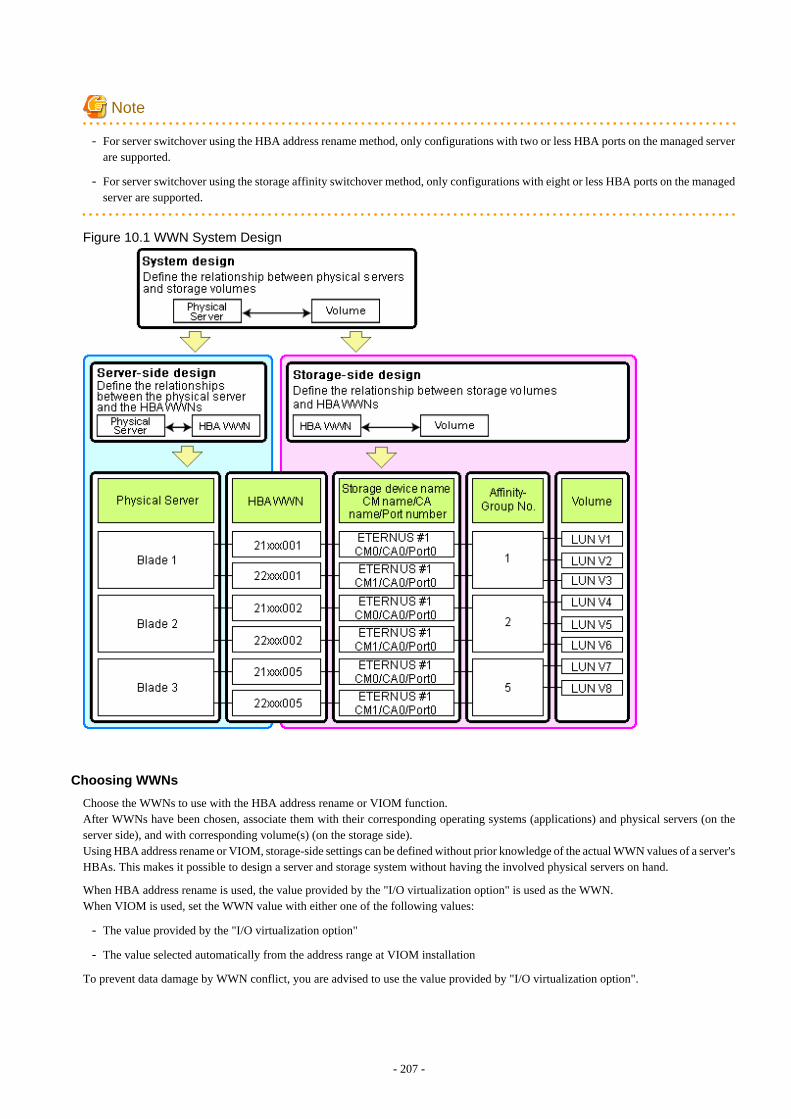
Note
- For server switchover using the HBA address rename method, only configurations with two or less HBA ports on the managed serverare supported.
- For server switchover using the storage affinity switchover method, only configurations with eight or less HBA ports on the managedserver are supported.
Figure 10.1 WWN System Design
Choosing WWNs
Choose the WWNs to use with the HBA address rename or VIOM function.After WWNs have been chosen, associate them with their corresponding operating systems (applications) and physical servers (on theserver side), and with corresponding volume(s) (on the storage side).Using HBA address rename or VIOM, storage-side settings can be defined without prior knowledge of the actual WWN values of a server'sHBAs. This makes it possible to design a server and storage system without having the involved physical servers on hand.
When HBA address rename is used, the value provided by the "I/O virtualization option" is used as the WWN.When VIOM is used, set the WWN value with either one of the following values:
- The value provided by the "I/O virtualization option"
- The value selected automatically from the address range at VIOM installation
To prevent data damage by WWN conflict, you are advised to use the value provided by "I/O virtualization option".
- 207 -
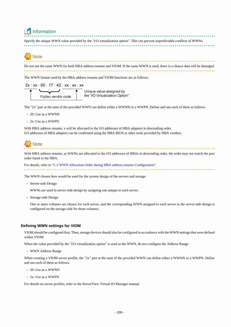
Information
Specify the unique WWN value provided by the "I/O virtualization option". This can prevent unpredictable conflicts of WWNs.
Note
Do not use the same WWN for both HBA address rename and VIOM. If the same WWN is used, there is a chance data will be damaged.
The WWN format used by the HBA address rename and VIOM functions are as follows:
The "2x" part at the start of the provided WWN can define either a WWNN or a WWPN. Define and use each of them as follows.
- 20: Use as a WWNN
- 2x: Use as a WWPN
With HBA address rename, x will be allocated to the I/O addresses of HBA adapters in descending order.I/O addresses of HBA adapters can be confirmed using the HBA BIOS or other tools provided by HBA vendors.
Note
With HBA address rename, as WWNs are allocated to the I/O addresses of HBAs in descending order, the order may not match the portorder listed in the HBA.
For details, refer to "C.2 WWN Allocation Order during HBA address rename Configuration".
The WWN chosen here would be used for the system design of the servers and storage.
- Server-side Design
WWNs are used in server-side design by assigning one unique to each server.
- Storage-side Design
One or more volumes are chosen for each server, and the corresponding WWN assigned to each server in the server-side design isconfigured on the storage-side for those volumes.
Defining WWN settings for VIOM
VIOM should be configured first. Then, storage devices should also be configured in accordance with the WWN settings that were definedwithin VIOM.
When the value provided by the "I/O virtualization option" is used as the WWN, do not configure the Address Range.
- WWN Address Range
When creating a VIOM server profile, the "2x" part at the start of the provided WWN can define either a WWNN or a WWPN. Defineand use each of them as follows.
- 20: Use as a WWNN
- 2x: Use as a WWPN
For details on server profiles, refer to the ServerView Virtual-IO Manager manual.
- 208 -
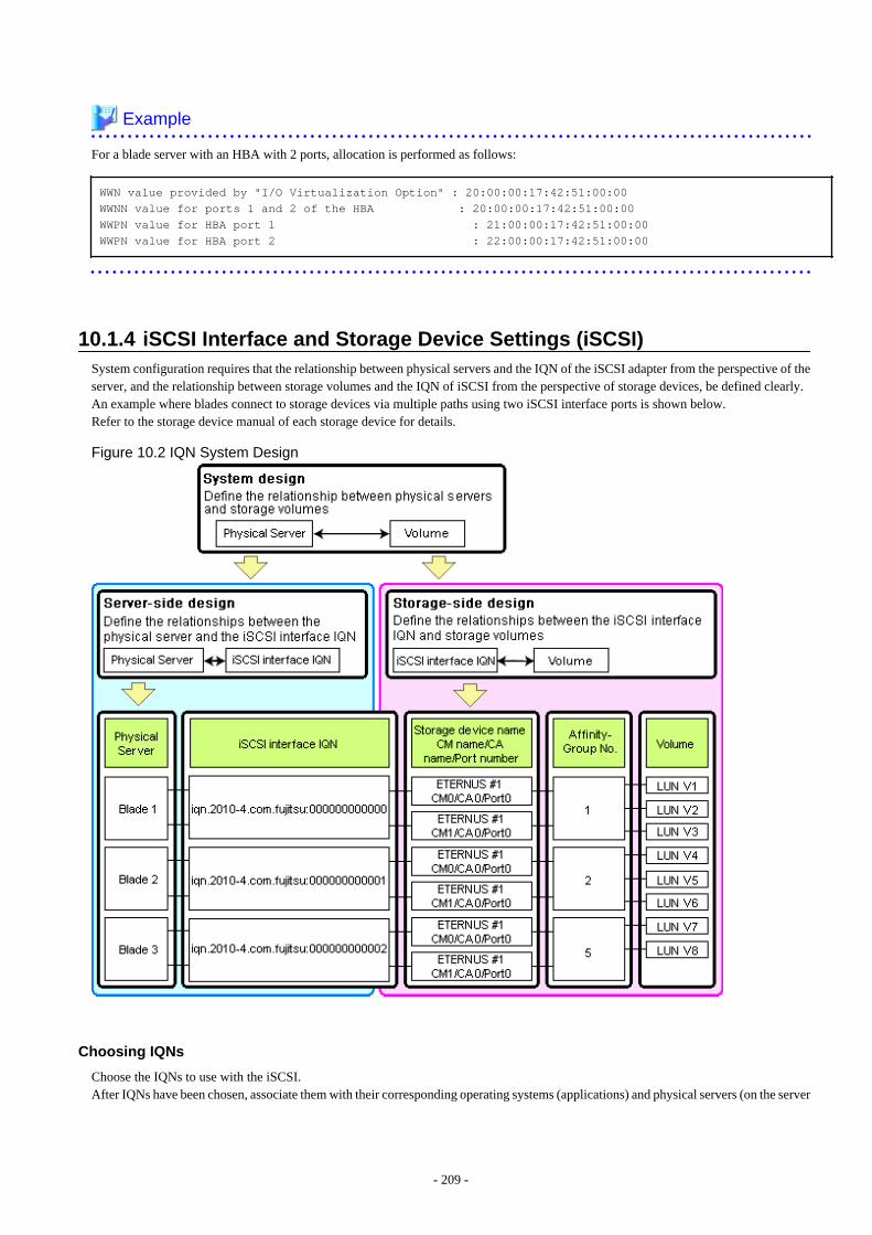
Example
For a blade server with an HBA with 2 ports, allocation is performed as follows:
WWN value provided by "I/O Virtualization Option" : 20:00:00:17:42:51:00:00WWNN value for ports 1 and 2 of the HBA : 20:00:00:17:42:51:00:00WWPN value for HBA port 1 : 21:00:00:17:42:51:00:00WWPN value for HBA port 2 : 22:00:00:17:42:51:00:00
10.1.4 iSCSI Interface and Storage Device Settings (iSCSI)System configuration requires that the relationship between physical servers and the IQN of the iSCSI adapter from the perspective of theserver, and the relationship between storage volumes and the IQN of iSCSI from the perspective of storage devices, be defined clearly.An example where blades connect to storage devices via multiple paths using two iSCSI interface ports is shown below.Refer to the storage device manual of each storage device for details.
Figure 10.2 IQN System Design
Choosing IQNs
Choose the IQNs to use with the iSCSI.After IQNs have been chosen, associate them with their corresponding operating systems (applications) and physical servers (on the server
- 209 -
side), and with corresponding volume(s) (on the storage side).IQNs are made up of the following:
- Type identifier "iqn."
- Domain acquisition date
- Domain name
- Character string assigned by domain acquirer
IQNs must be unique.Create a unique IQN by using the server name, or the MAC address provided by the "I/O virtualization option" that is to be allocated tothe network interface of the server, as part of the IQN.If IQNs overlap, there is a chance that data will be damaged when accessed simultaneously.An example of using the virtual MAC address allocated by the "I/O virtualization option" is given below.
Example
When the MAC address is 00:00:00:00:00:FF
IQN iqn.2010-04.com.fujitsu:0000000000ff
The IQN chosen here would be used for the system design of the servers and storage.
- Server-side Design
IQNs are used in server-side design by assigning one unique to each server.
- Storage-side Design
One or more volumes are chosen for each server, and the corresponding IQN assigned to each server in the server-side design isconfigured on the storage-side for those volumes.
10.2 Configuring the Storage EnvironmentThis section describes how to configure storage devices for Resource Orchestrator.
The settings differ depending on whether the L-Server is physical or virtual.
When Using Physical L-Servers
- Configure SAN Storage Environments
- Configure HBA address rename or VIOM coordination
Configure the HBA address rename function or VIOM coordination in advance.
- Configure the storage and fibre channel switch, install and set up storage management software
With physical L-Servers, virtual storage resources and disk resources are controlled via storage management software.
When allocating disk resources automatically created from virtual storage to physical L-Servers, create the virtual storage resourcessuch as RAID groups or aggregates in advance.
When allocating disk resources to physical L-Servers, create the disk resources such as LUNs in advance.
- When using ETERNUS storage
Refer to "D.3.3 When Using ETERNUS Storage".
- When using NetApp FAS storage
Refer to "D.3.4 When Using NetApp FAS Storage".
- When using EMC CLARiiON storage or EMC VNX Storage
Refer to "D.3.5 When Using EMC CLARiiON Storage or EMC VNX Storage".
- 210 -
- When using EMC Symmetrix DMX storage or EMC Symmetrix VMAX storage
Refer to "D.3.6 When Using EMC Symmetrix DMX Storage or EMC Symmetrix VMAX Storage".
- When using Storage Server on which FalconStor NSS operates
Refer to "D.3.7 When Using Storage Server on which FalconStor NSS Operates".
- Configure iSCSI Storage Environments
- Configure the storage and fibre channel switch, install and set up storage management software
When using iSCSI boot on physical L-Servers, create LUNs that can be connected to L-Servers in advance.
- When using ETERNUS storage
Refer to "D.3.3 When Using ETERNUS Storage".
- When using NetApp FAS storage
Refer to "D.3.4 When Using NetApp FAS Storage".
When Using Virtual L-Servers
- Configure the storage and fibre channel switch, install and set up VM management software
Virtual L-Servers are controlled via VM management software.
Create the virtual storage resources such as datastores and the disk resources such as raw devices in advance.
- When Using VMware
Refer to "Preparations for Storage Environments" in "E.1.3 Storage Preparations".
- When Using Hyper-V
Refer to "Preparations for Storage Environments" in "E.2.3 Storage Preparations".
- When Using RHEL5-Xen
Refer to "Preparations for Storage Environments" in "E.3.3 Storage Preparations".
- When Using OVM for x86 2.2
Refer to "Preparations for Storage Environments" in "E.4.3 Storage Preparations".
- When Using RHEL-KVM
Refer to "Preparations for Storage Environments" in "E.5.3 Storage Preparations".
- When Using Solaris Zones
Refer to "Preparations for Storage Environments" in "E.6.3 Storage Preparations".
- When Using OVM for SPARC
Refer to "Preparations for Storage Environments" in "E.7.3 Storage Preparations".
- When Using Citrix XenServer
Refer to "E.8.3 Preparations for Storage".
- When Using OVM for x86 3.2
Refer to "E.9.3 Preparations for Storage".
- 211 -
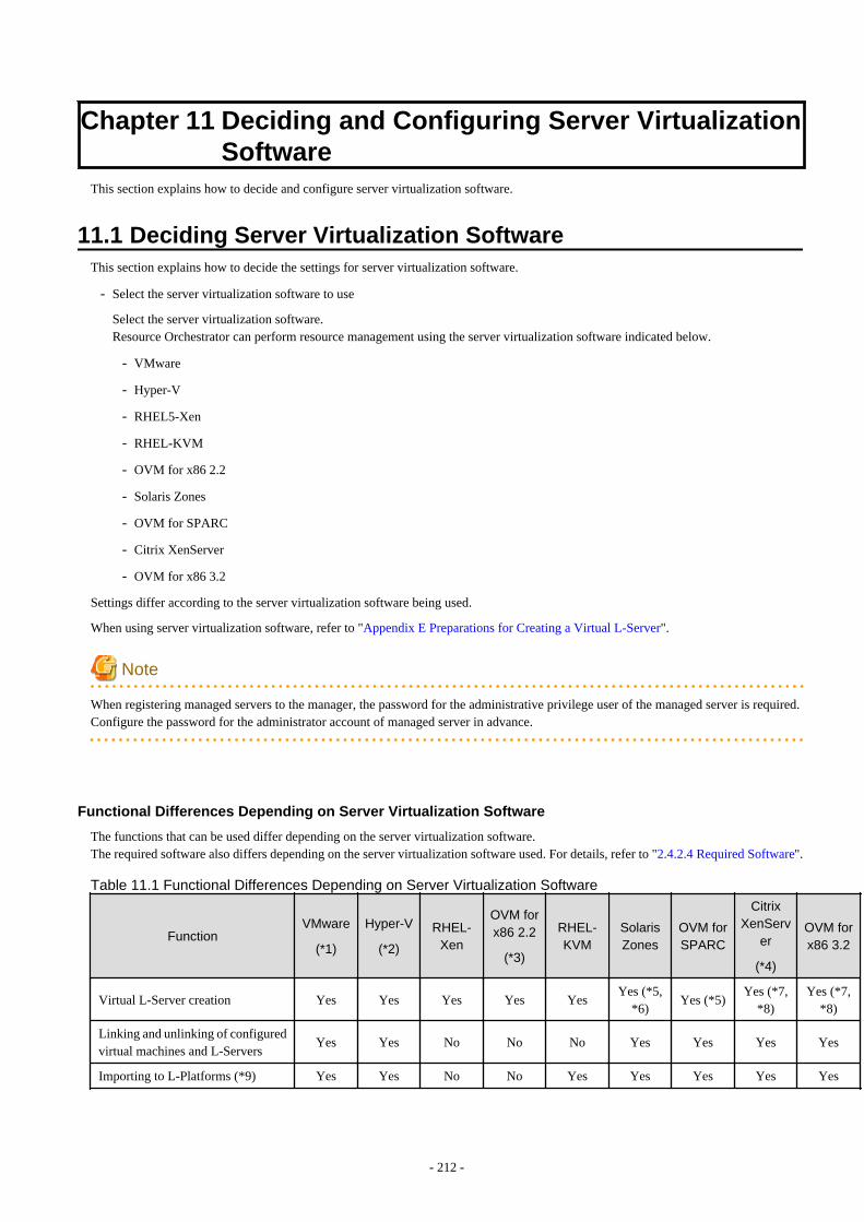
Chapter 11 Deciding and Configuring Server VirtualizationSoftware
This section explains how to decide and configure server virtualization software.
11.1 Deciding Server Virtualization SoftwareThis section explains how to decide the settings for server virtualization software.
- Select the server virtualization software to use
Select the server virtualization software.Resource Orchestrator can perform resource management using the server virtualization software indicated below.
- VMware
- Hyper-V
- RHEL5-Xen
- RHEL-KVM
- OVM for x86 2.2
- Solaris Zones
- OVM for SPARC
- Citrix XenServer
- OVM for x86 3.2
Settings differ according to the server virtualization software being used.
When using server virtualization software, refer to "Appendix E Preparations for Creating a Virtual L-Server".
Note
When registering managed servers to the manager, the password for the administrative privilege user of the managed server is required.Configure the password for the administrator account of managed server in advance.
Functional Differences Depending on Server Virtualization Software
The functions that can be used differ depending on the server virtualization software.The required software also differs depending on the server virtualization software used. For details, refer to "2.4.2.4 Required Software".
Table 11.1 Functional Differences Depending on Server Virtualization Software
FunctionVMware
(*1)
Hyper-V
(*2)
RHEL-Xen
OVM forx86 2.2
(*3)
RHEL-KVM
SolarisZones
OVM forSPARC
CitrixXenServ
er
(*4)
OVM forx86 3.2
Virtual L-Server creation Yes Yes Yes Yes YesYes (*5,
*6)Yes (*5)
Yes (*7,*8)
Yes (*7,*8)
Linking and unlinking of configuredvirtual machines and L-Servers
Yes Yes No No No Yes Yes Yes Yes
Importing to L-Platforms (*9) Yes Yes No No Yes Yes Yes Yes Yes
- 212 -
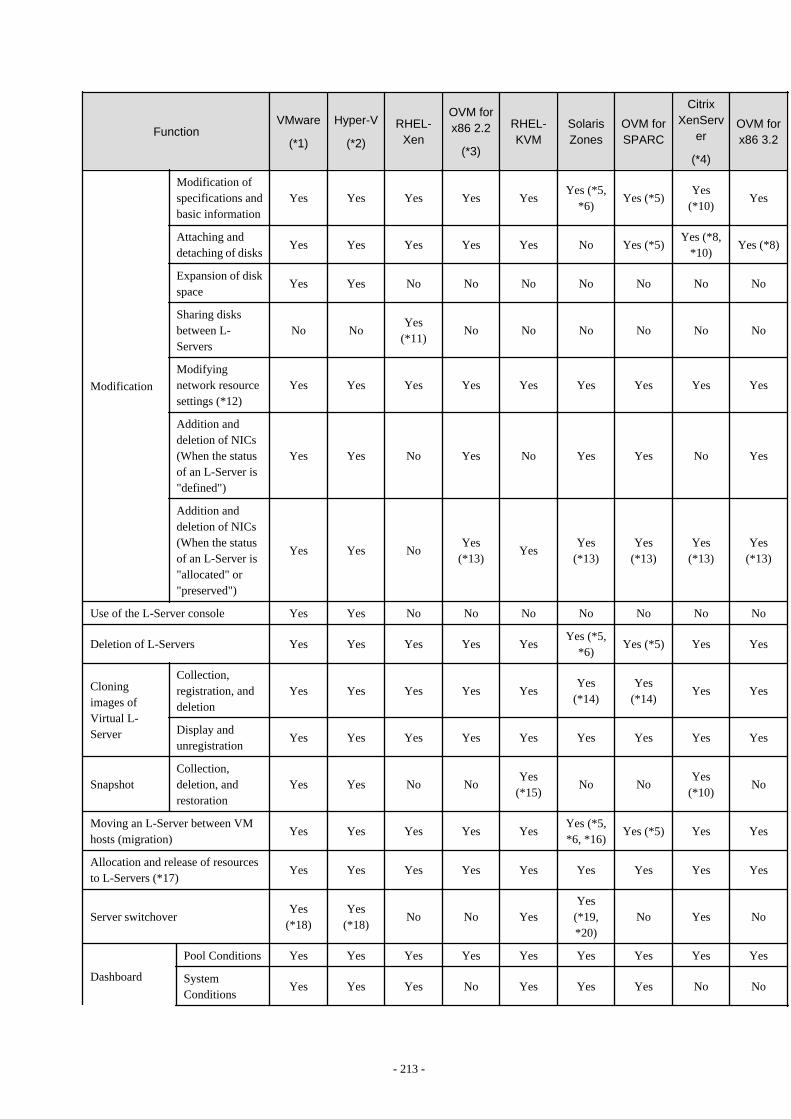
FunctionVMware
(*1)
Hyper-V
(*2)
RHEL-Xen
OVM forx86 2.2
(*3)
RHEL-KVM
SolarisZones
OVM forSPARC
CitrixXenServ
er
(*4)
OVM forx86 3.2
Modification
Modification ofspecifications andbasic information
Yes Yes Yes Yes YesYes (*5,
*6)Yes (*5)
Yes(*10)
Yes
Attaching anddetaching of disks
Yes Yes Yes Yes Yes No Yes (*5)Yes (*8,
*10)Yes (*8)
Expansion of diskspace
Yes Yes No No No No No No No
Sharing disksbetween L-Servers
No NoYes
(*11)No No No No No No
Modifyingnetwork resourcesettings (*12)
Yes Yes Yes Yes Yes Yes Yes Yes Yes
Addition anddeletion of NICs(When the statusof an L-Server is"defined")
Yes Yes No Yes No Yes Yes No Yes
Addition anddeletion of NICs(When the statusof an L-Server is"allocated" or"preserved")
Yes Yes NoYes
(*13)Yes
Yes(*13)
Yes(*13)
Yes(*13)
Yes(*13)
Use of the L-Server console Yes Yes No No No No No No No
Deletion of L-Servers Yes Yes Yes Yes YesYes (*5,
*6)Yes (*5) Yes Yes
Cloningimages ofVirtual L-Server
Collection,registration, anddeletion
Yes Yes Yes Yes YesYes
(*14)Yes
(*14)Yes Yes
Display andunregistration
Yes Yes Yes Yes Yes Yes Yes Yes Yes
SnapshotCollection,deletion, andrestoration
Yes Yes No NoYes
(*15)No No
Yes(*10)
No
Moving an L-Server between VMhosts (migration)
Yes Yes Yes Yes YesYes (*5,*6, *16)
Yes (*5) Yes Yes
Allocation and release of resourcesto L-Servers (*17)
Yes Yes Yes Yes Yes Yes Yes Yes Yes
Server switchoverYes
(*18)Yes
(*18)No No Yes
Yes(*19,*20)
No Yes No
Dashboard
Pool Conditions Yes Yes Yes Yes Yes Yes Yes Yes Yes
SystemConditions
Yes Yes Yes No Yes Yes Yes No No
- 213 -
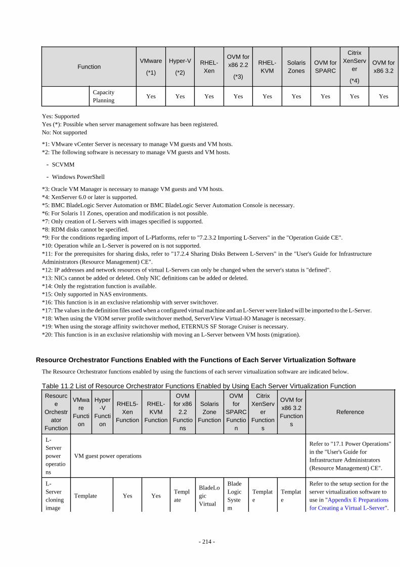
FunctionVMware
(*1)
Hyper-V
(*2)
RHEL-Xen
OVM forx86 2.2
(*3)
RHEL-KVM
SolarisZones
OVM forSPARC
CitrixXenServ
er
(*4)
OVM forx86 3.2
CapacityPlanning
Yes Yes Yes Yes Yes Yes Yes Yes Yes
Yes: SupportedYes (*): Possible when server management software has been registered.No: Not supported
*1: VMware vCenter Server is necessary to manage VM guests and VM hosts.*2: The following software is necessary to manage VM guests and VM hosts.
- SCVMM
- Windows PowerShell
*3: Oracle VM Manager is necessary to manage VM guests and VM hosts.*4: XenServer 6.0 or later is supported.*5: BMC BladeLogic Server Automation or BMC BladeLogic Server Automation Console is necessary.*6: For Solaris 11 Zones, operation and modification is not possible.*7: Only creation of L-Servers with images specified is supported.*8: RDM disks cannot be specified.*9: For the conditions regarding import of L-Platforms, refer to "7.2.3.2 Importing L-Servers" in the "Operation Guide CE".*10: Operation while an L-Server is powered on is not supported.*11: For the prerequisites for sharing disks, refer to "17.2.4 Sharing Disks Between L-Servers" in the "User's Guide for InfrastructureAdministrators (Resource Management) CE".*12: IP addresses and network resources of virtual L-Servers can only be changed when the server's status is "defined".*13: NICs cannot be added or deleted. Only NIC definitions can be added or deleted.*14: Only the registration function is available.*15: Only supported in NAS environments.*16: This function is in an exclusive relationship with server switchover.*17: The values in the definition files used when a configured virtual machine and an L-Server were linked will be imported to the L-Server.*18: When using the VIOM server profile switchover method, ServerView Virtual-IO Manager is necessary.*19: When using the storage affinity switchover method, ETERNUS SF Storage Cruiser is necessary.*20: This function is in an exclusive relationship with moving an L-Server between VM hosts (migration).
Resource Orchestrator Functions Enabled with the Functions of Each Server Virtualization Software
The Resource Orchestrator functions enabled by using the functions of each server virtualization software are indicated below.
Table 11.2 List of Resource Orchestrator Functions Enabled by Using Each Server Virtualization FunctionResourc
eOrchestr
atorFunction
VMware
Function
Hyper-V
Function
RHEL5-Xen
Function
RHEL-KVM
Function
OVMfor x86
2.2Functio
ns
SolarisZone
Function
OVMfor
SPARCFunctio
n
CitrixXenServ
erFunction
s
OVM forx86 3.2Function
s
Reference
L-Serverpoweroperations
VM guest power operations
Refer to "17.1 Power Operations"in the "User's Guide forInfrastructure Administrators(Resource Management) CE".
L-Servercloningimage
Template Yes YesTemplate
BladeLogicVirtual
BladeLogicSystem
Template
Template
Refer to the setup section for theserver virtualization software touse in "Appendix E Preparationsfor Creating a Virtual L-Server".
- 214 -

Resource
Orchestrator
Function
VMware
Function
Hyper-V
Function
RHEL5-Xen
Function
RHEL-KVM
Function
OVMfor x86
2.2Functio
ns
SolarisZone
Function
OVMfor
SPARCFunctio
n
CitrixXenServ
erFunction
s
OVM forx86 3.2Function
s
Reference
GuestPackage
Package
L-Serversnapshots
Snapshot
Checkpoints
-Snapshot
- - -Snapshot
-
Refer to "17.6 Snapshots, andBackup and Restoration of L-Servers" in the "User's Guide forInfrastructure Administrators(Resource Management) CE".
VM hostmaintenancemode
Maintenancemode
- -Maintenancemode
- -Maintenancemode
Maintenancemode
Refer to "15.2 VM MaintenanceMode of VM Hosts" in the "User'sGuide VE".
Movingan L-ServerbetweenVMhosts(migration)
Migration
Migrationusingclusters
Migration YesMigration
Migration
Migration
Refer to "17.7 Migration betweenVM Hosts" in the "User's Guidefor Infrastructure Administrators(Resource Management) CE".
Overcommit(CPU)
Reservation /Limit/Shares
Reservation /Limit/VirtualQuantityofVMs
- Yes - Yes Yes Yes Yes
[VMware]Refer to "C.2.11 Overcommit" inthe "Setup Guide CE".
[Hyper-V]Refer to "C.3.11 Overcommit" inthe "Setup Guide CE".
[KVM]Refer to "C.6.10 Overcommit" inthe "Setup Guide CE".
[Solaris Zones]Refer to "C.7.9 Overcommit" inthe "Setup Guide CE".
[OVM for SPARC]Refer to "C.8.9 Overcommit" inthe "Setup Guide CE".
[Citrix Xen]Refer to "C.9.11 Overcommit" inthe "Setup Guide CE".
[OVM for x86 3.2]Refer to "C.10.11 Overcommit" inthe "Setup Guide CE".
Overcommit(memory)
Reservation /Limit/Shares
DynamicMemory
- Yes - Yes Yes Yes Yes
[VMware]Refer to "C.2.11 Overcommit" inthe "Setup Guide CE".
[Hyper-V]Refer to "C.3.11 Overcommit" inthe "Setup Guide CE".
- 215 -

Resource
Orchestrator
Function
VMware
Function
Hyper-V
Function
RHEL5-Xen
Function
RHEL-KVM
Function
OVMfor x86
2.2Functio
ns
SolarisZone
Function
OVMfor
SPARCFunctio
n
CitrixXenServ
erFunction
s
OVM forx86 3.2Function
s
Reference
[KVM]Refer to "C.6.10 Overcommit" inthe "Setup Guide CE".
[Solaris Zones]Refer to "C.7.9 Overcommit" inthe "Setup Guide CE".
[OVM for SPARC]Refer to "C.8.9 Overcommit" inthe "Setup Guide CE".
[Citrix Xen]Refer to "C.9.11 Overcommit" inthe "Setup Guide CE".
[OVM for x86 3.2]Refer to "C.10.11 Overcommit" inthe "Setup Guide CE".
ServerRecovery
Located onacluster forwhichVMwareHA isenabled
Located ontheMSFC
- -
Located on aserverpoolforwhichHA isenabled
Yes Yes
Locatedon aserverpool forwhichHA isenabled
Locatedon aserverpool forwhichHA isenabled
Refer to "16.3.2 [Server] Tab" inthe "User's Guide forInfrastructure Administrators(Resource Management) CE".
AliveMonitoring
VMwareHAClusterVMandApplicationMonitoring
MSFCHeartbeat
- - - - - - -
Refer to "16.3.2 [Server] Tab" inthe "User's Guide forInfrastructure Administrators(Resource Management) CE".
ThinProvisioning
ThinProvisioning
- -
Allocation ofqcow2sparsefiles
- - --
(*1)
Sparseallocation
Refer to "10.1.1 AllocatingStorage".
L-ServerConsole
VirtualMachine
VirtualMachine
- - - - - - -For details, refer to "17.3 Usingthe L-Server Console" in the"User's Guide for Infrastructure
- 216 -
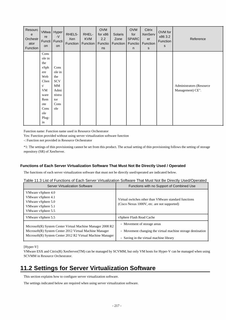
Resource
Orchestrator
Function
VMware
Function
Hyper-V
Function
RHEL5-Xen
Function
RHEL-KVM
Function
OVMfor x86
2.2Functio
ns
SolarisZone
Function
OVMfor
SPARCFunctio
n
CitrixXenServ
erFunction
s
OVM forx86 3.2Function
s
Reference
Console inthevSphereWebClient/VMwareRemoteConsolePlug-in
Console intheSCVMMAdministratorConsole
Administrators (ResourceManagement) CE".
Function name: Function name used in Resource OrchestratorYes: Function provided without using server virtualization software function-: Function not provided in Resource Orchestrator
*1: The settings of thin provisioning cannot be set from this product. The actual setting of thin provisioning follows the setting of storagerepository (SR) of XenServer.
Functions of Each Server Virtualization Software That Must Not Be Directly Used / Operated
The functions of each server virtualization software that must not be directly used/operated are indicated below.
Table 11.3 List of Functions of Each Server Virtualization Software That Must Not Be Directly Used/Operated
Server Virtualization Software Functions with no Support of Combined Use
VMware vSphere 4.0VMware vSphere 4.1VMware vSphere 5.0VMware vSphere 5.1VMware vSphere 5.5
Virtual switches other than VMware standard functions(Cisco Nexus 1000V, etc. are not supported)
VMware vSphere 5.5 vSphere Flash Read Cache
Microsoft(R) System Center Virtual Machine Manager 2008 R2Microsoft(R) System Center 2012 Virtual Machine ManagerMicrosoft(R) System Center 2012 R2 Virtual Machine Manager
- Movement of storage areas
- Movement changing the virtual machine storage destination
- Saving in the virtual machine library
[Hyper-V]VMware ESX and Citrix(R) XenServer(TM) can be managed by SCVMM, but only VM hosts for Hyper-V can be managed when usingSCVMM in Resource Orchestrator.
11.2 Settings for Server Virtualization SoftwareThis section explains how to configure server virtualization software.
The settings indicated below are required when using server virtualization software.
- 217 -
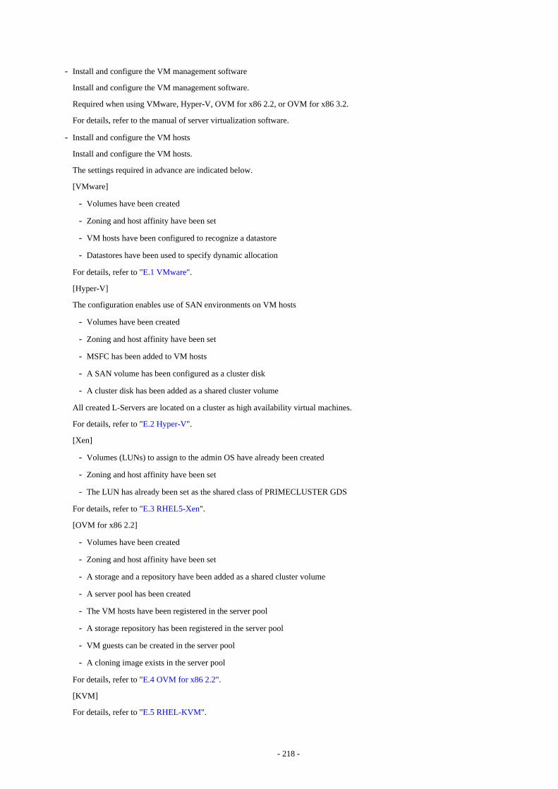
- Install and configure the VM management software
Install and configure the VM management software.
Required when using VMware, Hyper-V, OVM for x86 2.2, or OVM for x86 3.2.
For details, refer to the manual of server virtualization software.
- Install and configure the VM hosts
Install and configure the VM hosts.
The settings required in advance are indicated below.
[VMware]
- Volumes have been created
- Zoning and host affinity have been set
- VM hosts have been configured to recognize a datastore
- Datastores have been used to specify dynamic allocation
For details, refer to "E.1 VMware".
[Hyper-V]
The configuration enables use of SAN environments on VM hosts
- Volumes have been created
- Zoning and host affinity have been set
- MSFC has been added to VM hosts
- A SAN volume has been configured as a cluster disk
- A cluster disk has been added as a shared cluster volume
All created L-Servers are located on a cluster as high availability virtual machines.
For details, refer to "E.2 Hyper-V".
[Xen]
- Volumes (LUNs) to assign to the admin OS have already been created
- Zoning and host affinity have been set
- The LUN has already been set as the shared class of PRIMECLUSTER GDS
For details, refer to "E.3 RHEL5-Xen".
[OVM for x86 2.2]
- Volumes have been created
- Zoning and host affinity have been set
- A storage and a repository have been added as a shared cluster volume
- A server pool has been created
- The VM hosts have been registered in the server pool
- A storage repository has been registered in the server pool
- VM guests can be created in the server pool
- A cloning image exists in the server pool
For details, refer to "E.4 OVM for x86 2.2".
[KVM]
For details, refer to "E.5 RHEL-KVM".
- 218 -

[Solaris Zones]
For details, refer to "E.6 Solaris Zones".
[OVM for SPARC]
For details, refer to "E.7 OVM for SPARC".
[Citrix Xen]
For details, refer to "E.8 Citrix XenServer".
[OVM for x86 3.2]
For details, refer to "E.9 OVM for x86 3.2".
- 219 -
Chapter 12 Installing and Defining Single Sign-OnThe Single Sign-On function of ServerView Operations Manager is used for user authentication in Resource Orchestrator. When usingthe Single Sign-On function of ServerView Operations Manager, authentication is performed using the user information managed by theDirectory Service.
The flow of Single Sign-On installation is as follows.
1. Install ServerView Operations Manager
2. Register administrator users in the Directory Service in Resource Orchestrator
3. Install Resource Orchestrator
This section explains how to configure ServerView Operations Manager and the directory service environment.
When upgrading Resource Orchestrator from earlier versions, configure the Single Sign-On environment, referring to "F.6 Configuringa Single Sign-On Environment" in the "Setup Guide CE".
12.1 Deciding the Directory Service to UseDecide the directory service to use with the ServerView Operations Manager function. The directory services which can be used in ResourceOrchestrator use the ServerView Operations Manager settings.
- OpenDS provided with ServerView Operations Manager
OpenDJ is provided as the directory service with ServerView Operations Manager V6.1 and later.In the following explanation, take "OpenDS" as meaning "OpenDJ".
- Active Directory
When already using Active Directory for user management of another system, it can be used instead of the OpenDS provided withServerView Operations Manager.
Note
After deployment of Resource Orchestrator, only the password of the directory server's administrator can be changed.
12.2 Setting Up ServerView Operations Manager and the DirectoryService Environment
Set up ServerView Operations Manager and the Directory Service Environment.The following settings can be made for coordination of Resource Orchestrator and a directory service.
- Coordination with the User Registration Directory Service
- To Use a User already Registered with Active Directory as a Resource Orchestrator User
- Single Sign-On When Using the ServerView Operations Manager Console
- When Installing ServerView Operations Manager Again
Note
Do not modify the LDAP port number of OpenDS.
- 220 -
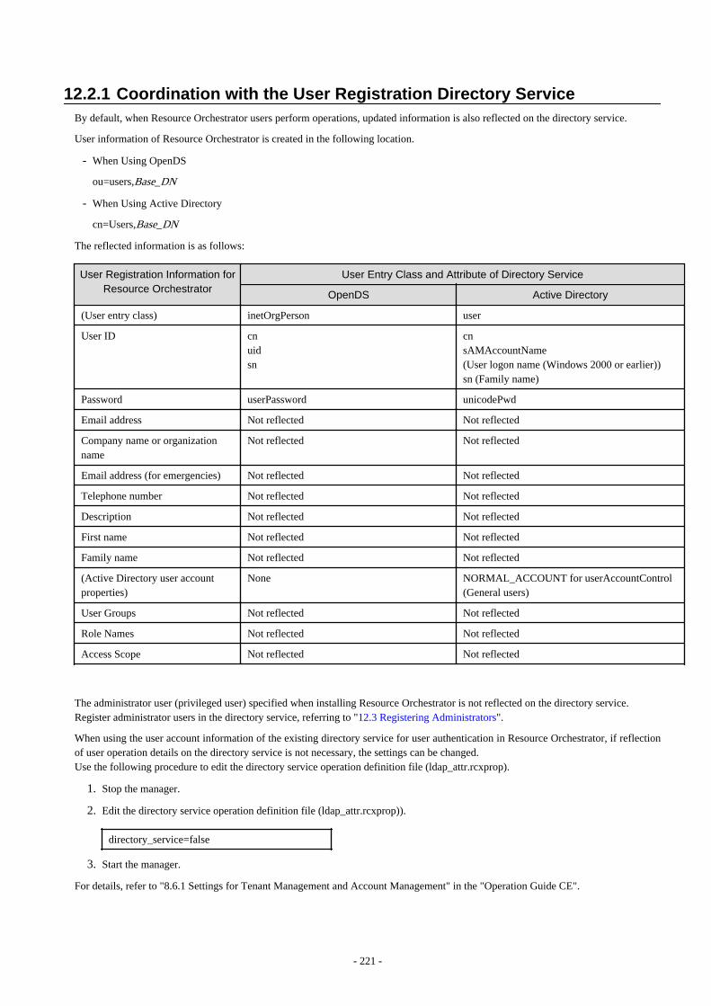
12.2.1 Coordination with the User Registration Directory ServiceBy default, when Resource Orchestrator users perform operations, updated information is also reflected on the directory service.
User information of Resource Orchestrator is created in the following location.
- When Using OpenDS
ou=users,Base_DN
- When Using Active Directory
cn=Users,Base_DN
The reflected information is as follows:
User Registration Information for
Resource OrchestratorUser Entry Class and Attribute of Directory Service
OpenDS Active Directory
(User entry class) inetOrgPerson user
User ID cnuidsn
cnsAMAccountName(User logon name (Windows 2000 or earlier))sn (Family name)
Password userPassword unicodePwd
Email address Not reflected Not reflected
Company name or organizationname
Not reflected Not reflected
Email address (for emergencies) Not reflected Not reflected
Telephone number Not reflected Not reflected
Description Not reflected Not reflected
First name Not reflected Not reflected
Family name Not reflected Not reflected
(Active Directory user accountproperties)
None NORMAL_ACCOUNT for userAccountControl(General users)
User Groups Not reflected Not reflected
Role Names Not reflected Not reflected
Access Scope Not reflected Not reflected
The administrator user (privileged user) specified when installing Resource Orchestrator is not reflected on the directory service.Register administrator users in the directory service, referring to "12.3 Registering Administrators".
When using the user account information of the existing directory service for user authentication in Resource Orchestrator, if reflectionof user operation details on the directory service is not necessary, the settings can be changed.Use the following procedure to edit the directory service operation definition file (ldap_attr.rcxprop).
1. Stop the manager.
2. Edit the directory service operation definition file (ldap_attr.rcxprop)).
directory_service=false
3. Start the manager.
For details, refer to "8.6.1 Settings for Tenant Management and Account Management" in the "Operation Guide CE".
- 221 -
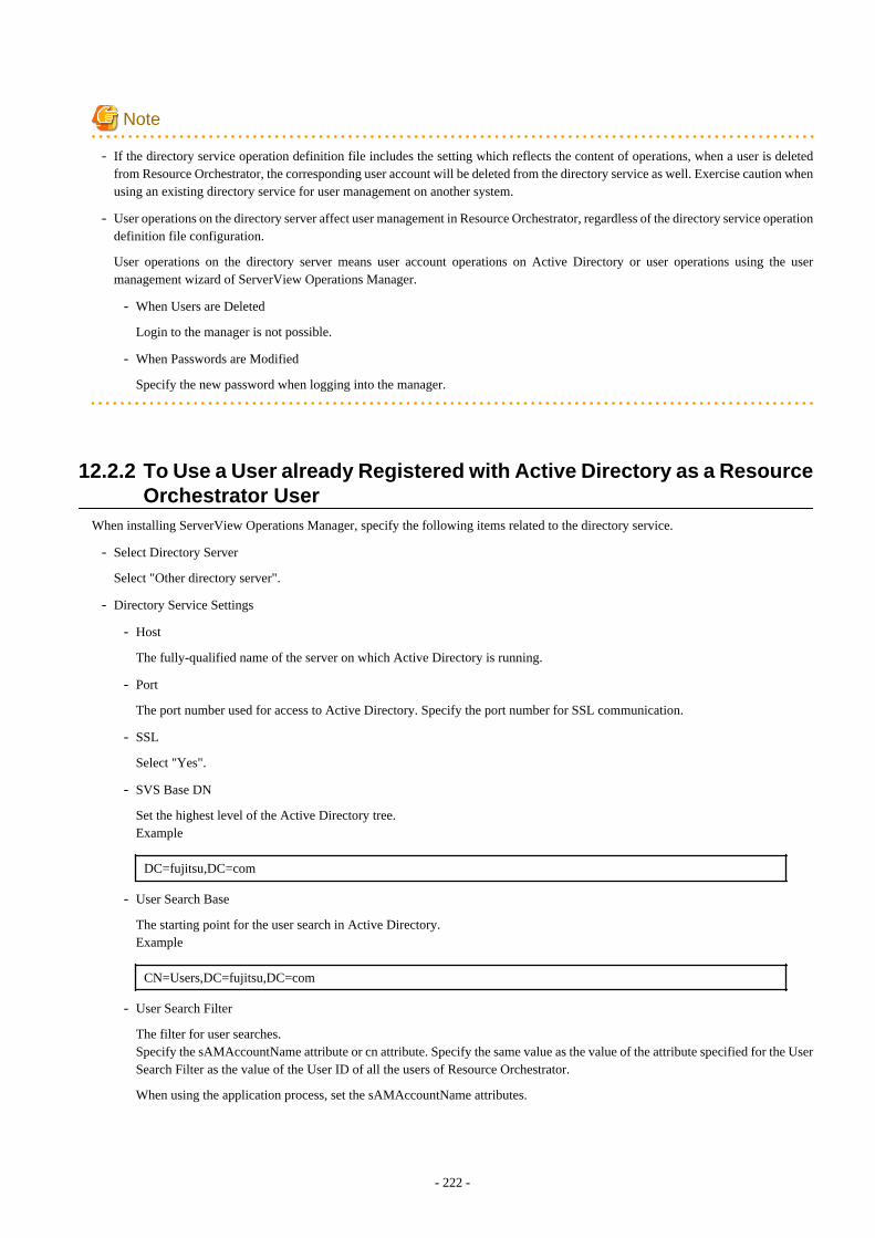
Note
- If the directory service operation definition file includes the setting which reflects the content of operations, when a user is deletedfrom Resource Orchestrator, the corresponding user account will be deleted from the directory service as well. Exercise caution whenusing an existing directory service for user management on another system.
- User operations on the directory server affect user management in Resource Orchestrator, regardless of the directory service operationdefinition file configuration.
User operations on the directory server means user account operations on Active Directory or user operations using the usermanagement wizard of ServerView Operations Manager.
- When Users are Deleted
Login to the manager is not possible.
- When Passwords are Modified
Specify the new password when logging into the manager.
12.2.2 To Use a User already Registered with Active Directory as a ResourceOrchestrator User
When installing ServerView Operations Manager, specify the following items related to the directory service.
- Select Directory Server
Select "Other directory server".
- Directory Service Settings
- Host
The fully-qualified name of the server on which Active Directory is running.
- Port
The port number used for access to Active Directory. Specify the port number for SSL communication.
- SSL
Select "Yes".
- SVS Base DN
Set the highest level of the Active Directory tree.Example
DC=fujitsu,DC=com
- User Search Base
The starting point for the user search in Active Directory.Example
CN=Users,DC=fujitsu,DC=com
- User Search Filter
The filter for user searches.Specify the sAMAccountName attribute or cn attribute. Specify the same value as the value of the attribute specified for the UserSearch Filter as the value of the User ID of all the users of Resource Orchestrator.
When using the application process, set the sAMAccountName attributes.
- 222 -

sAMAccountName=%u
- User
Specify a user account with write privileges for Active Directory.Example
CN=Administrator,CN=Users,DC=fujitsu,DC=com
- Password / Confirm password
Specify the password of the user who specified it as the "User".
For more details, refer to the following manual.
- "Menu-Driven Installation of the Operations Manager Software" in the "ServerView Suite ServerView Operations ManagerInstallation Guide"
For details on how to change the directory service of ServerView Operations Manager, refer to the following manual.
- "Configuring directory service access" in "ServerView Suite User Management in ServerView"
[Windows Manager]When setting up Resource Orchestrator, it is necessary to establish communication beforehand, since communication between the managerand the directory service requires LDAP (Lightweight Directory Access Protocol) of the TCP/IP protocol protected by SSL. Use tools orcommands to check communications.
Right-click the certificate issued by the Certification Authority, and install the certificate using the certificate import wizard.
For details, refer to the Microsoft web site below.
How to enable LDAP over SSL with a third-party certification authority
URL: http://support.microsoft.com/kb/321051/en/
12.2.3 Single Sign-On When Using the ServerView Operations ManagerConsole
In the "Resource" tab of the ROR console, you can open the screen of ServerView Operations Manager using the function to open theserver management screen. This section explains how to set up Single Sign-on. You can use it access the server management screen ofServerView Operations Manager without being prompted to log in.
Perform user role assignment or release on ServerView Operations Manager.
When Registering Users
Assign roles to users in the following procedure.
When Using OpenDS Provided with ServerView Operations Manager
- ServerView Operations Manager V5.5 or later
1. Register a user from the ROR console.
2. The user is registered in the directory service
3. Start the "User Management Wizard" of ServerView Operations Manager.
4. The user registered in step 2 is displayed in the list. Assign a suitable role to the user.
- Versions earlier than ServerView Operations Manager V5.5
1. Register a user from the ROR console.
2. The user is registered in the directory service
- 223 -

3. Create an ldif file.
An example of how to assign the Administrator role to the "rormanager" user account is indicated below.
dn: cn=Administrator,OU=AuthorizationRoles,OU=CMS,OU=Departments,OU=SVS,dc=fujitsu,dc=comchangetype: modifyadd: membermember: cn=rormanager,ou=users,dc=fujitsu,dc=com
dn:cn=Administrator,OU=AuthorizationRoles,OU=DEFAULT,OU=Departments,OU=SVS,dc=fujitsu,dc=comchangetype: modifyadd: membermember: cn=rormanager,ou=users,dc=fujitsu,dc=com
4. Execute the OpenDS ldapmodify command to register the ldif file created in step 3 with the directory service.
Set the Java SE 6 path for the environment variable JAVA_HOME, before executing the ldapmodify command of OpenDS.Example:
[Windows]
>"C:\Program Files\Fujitsu\ServerView Suite\opends\bat\ldapmodify.bat" -p 1473 -f user.ldif -D"cn=Directory Manager" -w admin -c <RETURN>
[Linux]
# /opt/fujitsu/ServerViewSuite/opends/bin/ldapmodify -p 1473 -f user.ldif -D "cn=Directory Manager" -wadmin -c <RETURN>
The meanings of the options of the ldapmodify command are as follow.
-p: the port number when not using SSL communications in the OpenDS (the default value is 1473).-f: the ldif file-D: the OpenDS administrator user DN("cn=Directory Manager")-w: the password of the OpenDS administrator user DN.
When Using Active Directory
Refer to the following manual.
- "Integrating ServerView user management into Microsoft Active Directory" of the "ServerView Suite User Management inServerView"
When Deleting Users
When Using OpenDS Provided with ServerView Operations Manager
Release the role assignment in ServerView Operations Manager first, then delete the users in Resource Orchestrator.
- ServerView Operations Manager V5.5 or later
1. Start the "User Management Wizard" of ServerView Operations Manager.
2. Registered user names are displayed. Delete all roles from the users to be deleted.
3. Delete the users from the ROR console.
The users will be deleted from OpenDS.
- 224 -
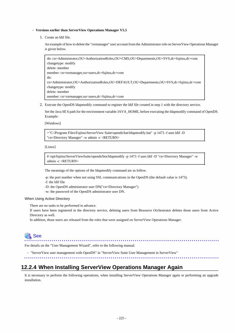
- Versions earlier than ServerView Operations Manager V5.5
1. Create an ldif file.
An example of how to delete the "rormanager" user account from the Administrator role on ServerView Operations Manageris given below.
dn: cn=Administrator,OU=AuthorizationRoles,OU=CMS,OU=Departments,OU=SVS,dc=fujitsu,dc=comchangetype: modifydelete: membermember: cn=rormanager,ou=users,dc=fujitsu,dc=comdn:cn=Administrator,OU=AuthorizationRoles,OU=DEFAULT,OU=Departments,OU=SVS,dc=fujitsu,dc=comchangetype: modifydelete: membermember: cn=rormanager,ou=users,dc=fujitsu,dc=com
2. Execute the OpenDS ldapmodify command to register the ldif file created in step 1 with the directory service.
Set the Java SE 6 path for the environment variable JAVA_HOME, before executing the ldapmodify command of OpenDS.Example:
[Windows]
>"C:\Program Files\Fujitsu\ServerView Suite\opends\bat\ldapmodify.bat" -p 1473 -f user.ldif -D"cn=Directory Manager" -w admin -c <RETURN>
[Linux]
# /opt/fujitsu/ServerViewSuite/opends/bin/ldapmodify -p 1473 -f user.ldif -D "cn=Directory Manager" -wadmin -c <RETURN>
The meanings of the options of the ldapmodify command are as follow.
-p: the port number when not using SSL communications in the OpenDS (the default value is 1473).-f: the ldif file-D: the OpenDS administrator user DN("cn=Directory Manager")-w: the password of the OpenDS administrator user DN.
When Using Active Directory
There are no tasks to be performed in advance.If users have been registered in the directory service, deleting users from Resource Orchestrator deletes those users from ActiveDirectory as well.In addition, those users are released from the roles that were assigned on ServerView Operations Manager.
See
For details on the "User Management Wizard", refer to the following manual.
- "ServerView user management with OpenDS" in "ServerView Suite User Management in ServerView"
12.2.4 When Installing ServerView Operations Manager AgainIt is necessary to perform the following operations, when installing ServerView Operations Manager again or performing an upgradeinstallation.
- 225 -
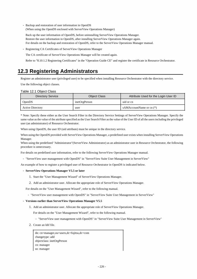
- Backup and restoration of user information in OpenDS(When using the OpenDS enclosed with ServerView Operations Manager)
Back up the user information of OpenDS, before uninstalling ServerView Operations Manager.Restore the user information in OpenDS, after installing ServerView Operations Manager again.For details on the backup and restoration of OpenDS, refer to the ServerView Operations Manager manual.
- Registering CA Certificates of ServerView Operations Manager
The CA certificate of ServerView Operations Manager will be created again.
Refer to "8.10.1.2 Registering Certificates" in the "Operation Guide CE" and register the certificate in Resource Orchestrator.
12.3 Registering AdministratorsRegister an administrator user (privileged user) to be specified when installing Resource Orchestrator with the directory service.
Use the following object classes.
Table 12.1 Object Class
Directory Service Object Class Attribute Used for the Login User ID
OpenDS inetOrgPerson uid or cn
Active Directory user sAMAccountName or cn (*)
* Note: Specify these either as the User Search Filter in the Directory Service Settings of ServerView Operations Manager. Specify thesame value as the value of the attribute specified as the User Search Filter as the value of the User ID of all the users including the privilegeduser (an administrator) of Resource Orchestrator.
When using OpenDS, the user ID (uid attribute) must be unique in the directory service.
When using the OpenDS provided with ServerView Operations Manager, a predefined user exists when installing ServerView OperationsManager.When using the predefined "Administrator"(ServerView Administrator) as an administrator user in Resource Orchestrator, the followingprocedure is unnecessary.
For details on predefined user information, refer to the following ServerView Operations Manager manual.
- "ServerView user management with OpenDS" in "ServerView Suite User Management in ServerView"
An example of how to register a privileged user of Resource Orchestrator in OpenDS is indicated below.
- ServerView Operations Manager V5.5 or later
1. Start the "User Management Wizard" of ServerView Operations Manager.
2. Add an administrator user. Allocate the appropriate role of ServerView Operations Manager.
For details on the "User Management Wizard", refer to the following manual.
- "ServerView user management with OpenDS" in "ServerView Suite User Management in ServerView"
- Versions earlier than ServerView Operations Manager V5.5
1. Add an administrator user. Allocate the appropriate role of ServerView Operations Manager.
For details on the "User Management Wizard", refer to the following manual.
- "ServerView user management with OpenDS" in "ServerView Suite User Management in ServerView"
2. Create an ldif file.
dn: cn=manager,ou=users,dc=fujitsu,dc=comchangetype: addobjectclass: inetOrgPersoncn: managersn: manager
- 226 -
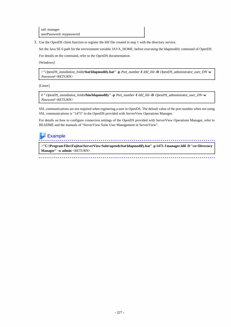
uid: manageruserPassword: mypassword
3. Use the OpenDS client function to register the ldif file created in step 1 with the directory service.
Set the Java SE 6 path for the environment variable JAVA_HOME, before executing the ldapmodify command of OpenDS.
For details on the command, refer to the OpenDS documentation.
[Windows]
>"OpenDS_installation_folder\bat\ldapmodify.bat" -p Port_number -f ldif_file -D OpenDS_administrator_user_DN -wPassword <RETURN>
[Linux]
# "OpenDS_installation_folder/bin/ldapmodify" -p Port_number -f ldif_file -D OpenDS_administrator_user_DN -wPassword <RETURN>
SSL communications are not required when registering a user in OpenDS. The default value of the port number when not usingSSL communications is "1473" in the OpenDS provided with ServerView Operations Manager.
For details on how to configure connection settings of the OpenDS provided with ServerView Operations Manager, refer toREADME and the manuals of "ServerView Suite User Management in ServerView".
Example
>"C:\Program Files\Fujitsu\ServerView Suite\opends\bat\ldapmodify.bat" -p 1473 -f manager.ldif -D "cn=DirectoryManager" -w admin <RETURN>
- 227 -
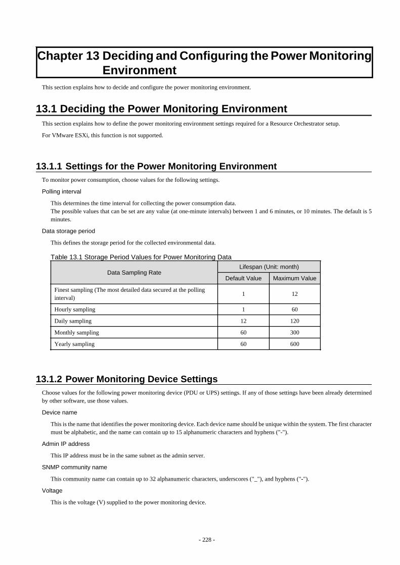
Chapter 13 Deciding and Configuring the Power MonitoringEnvironment
This section explains how to decide and configure the power monitoring environment.
13.1 Deciding the Power Monitoring EnvironmentThis section explains how to define the power monitoring environment settings required for a Resource Orchestrator setup.
For VMware ESXi, this function is not supported.
13.1.1 Settings for the Power Monitoring EnvironmentTo monitor power consumption, choose values for the following settings.
Polling interval
This determines the time interval for collecting the power consumption data.The possible values that can be set are any value (at one-minute intervals) between 1 and 6 minutes, or 10 minutes. The default is 5minutes.
Data storage period
This defines the storage period for the collected environmental data.
Table 13.1 Storage Period Values for Power Monitoring Data
Data Sampling RateLifespan (Unit: month)
Default Value Maximum Value
Finest sampling (The most detailed data secured at the pollinginterval)
1 12
Hourly sampling 1 60
Daily sampling 12 120
Monthly sampling 60 300
Yearly sampling 60 600
13.1.2 Power Monitoring Device SettingsChoose values for the following power monitoring device (PDU or UPS) settings. If any of those settings have been already determinedby other software, use those values.
Device name
This is the name that identifies the power monitoring device. Each device name should be unique within the system. The first charactermust be alphabetic, and the name can contain up to 15 alphanumeric characters and hyphens ("-").
Admin IP address
This IP address must be in the same subnet as the admin server.
SNMP community name
This community name can contain up to 32 alphanumeric characters, underscores ("_"), and hyphens ("-").
Voltage
This is the voltage (V) supplied to the power monitoring device.
- 228 -

Comments
These comments can be any description desired for the power monitoring device. The comments can contain up to 128 characters.
13.2 Configuring the Power Monitoring EnvironmentThis section describes how to configure power monitor devices for Resource Orchestrator.
Apply the following settings to power monitoring targets. Refer to the manual of each power monitoring target for configurationinstructions.
Admin IP address
This IP address is used by the admin server to communicate with a power monitoring target.
SNMP community name
This SNMP community name is used by the admin server to collect power consumption data from a power monitoring target (via theSNMP protocol).
- 229 -
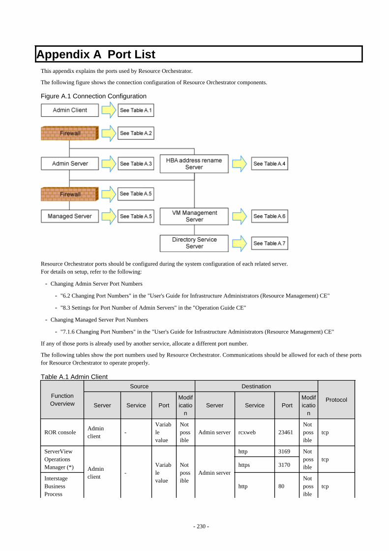
Appendix A Port ListThis appendix explains the ports used by Resource Orchestrator.
The following figure shows the connection configuration of Resource Orchestrator components.
Figure A.1 Connection Configuration
Resource Orchestrator ports should be configured during the system configuration of each related server.For details on setup, refer to the following:
- Changing Admin Server Port Numbers
- "6.2 Changing Port Numbers" in the "User's Guide for Infrastructure Administrators (Resource Management) CE"
- "8.3 Settings for Port Number of Admin Servers" in the "Operation Guide CE"
- Changing Managed Server Port Numbers
- "7.1.6 Changing Port Numbers" in the "User's Guide for Infrastructure Administrators (Resource Management) CE"
If any of those ports is already used by another service, allocate a different port number.
The following tables show the port numbers used by Resource Orchestrator. Communications should be allowed for each of these portsfor Resource Orchestrator to operate properly.
Table A.1 Admin Client
FunctionOverview
Source Destination
ProtocolServer Service Port
Modificatio
nServer Service Port
Modificatio
n
ROR consoleAdminclient
-Variablevalue
Notpossible
Admin server rcxweb 23461Notpossible
tcp
ServerViewOperationsManager (*) Admin
client-
Variablevalue
Notpossible
Admin server
http 3169 Notpossible
tcphttps 3170
InterstageBusinessProcess
http 80Notpossible
tcp
- 230 -
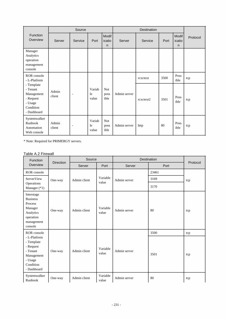
FunctionOverview
Source Destination
ProtocolServer Service Port
Modificatio
nServer Service Port
Modificatio
n
ManagerAnalyticsoperationmanagementconsole
ROR console- L-Platform- Template- TenantManagement- Request- UsageCondition- Dashboard
Adminclient
-Variablevalue
Notpossible
Admin server
rcxctext 3500Possible
tcp
rcxctext2 3501Possible
tcp
SystemwalkerRunbookAutomationWeb console
Adminclient
-Variablevalue
Notpossible
Admin server http 80Possible
tcp
* Note: Required for PRIMERGY servers.
Table A.2 Firewall
FunctionOverview
DirectionSource Destination
ProtocolServer Port Server Port
ROR console
One-way Admin clientVariablevalue
Admin server
23461
tcpServerViewOperationsManager (*1)
3169
3170
InterstageBusinessProcessManagerAnalyticsoperationmanagementconsole
One-way Admin clientVariablevalue
Admin server 80 tcp
ROR console- L-Platform- Template- Request- TenantManagement- UsageCondition- Dashboard
One-way Admin clientVariablevalue
Admin server
3500 tcp
3501 tcp
SystemwalkerRunbook
One-way Admin clientVariablevalue
Admin server 80 tcp
- 231 -
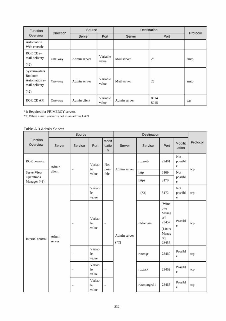
FunctionOverview
DirectionSource Destination
ProtocolServer Port Server Port
AutomationWeb console
ROR CE e-mail delivery
(*2)
One-way Admin serverVariablevalue
Mail server 25 smtp
SystemwalkerRunbookAutomation e-mail delivery
(*2)
One-way Admin serverVariablevalue
Mail server 25 smtp
ROR CE API One-way Admin clientVariablevalue
Admin server80148015
tcp
*1: Required for PRIMERGY servers.*2: When a mail server is not in an admin LAN
Table A.3 Admin Server
FunctionOverview
Source Destination
ProtocolServer Service Port
Modificatio
nServer Service Port
Modification
ROR console
Adminclient
-Variablevalue
Notpossible
Admin server
rcxweb 23461Notpossible
tcpServerViewOperationsManager (*1)
http 3169 Notpossiblehttps 3170
Internal controlAdminserver
-Variablevalue
-
Admin server
(*2)
- (*3) 3172Notpossible
tcp
-Variablevalue
- nfdomain
[WindowsManager]23457
[LinuxManager]23455
Possible
tcp
-Variablevalue
- rcxmgr 23460Possible
tcp
-Variablevalue
- rcxtask 23462Possible
tcp
-Variablevalue
- rcxmongrel1 23463Possible
tcp
- 232 -
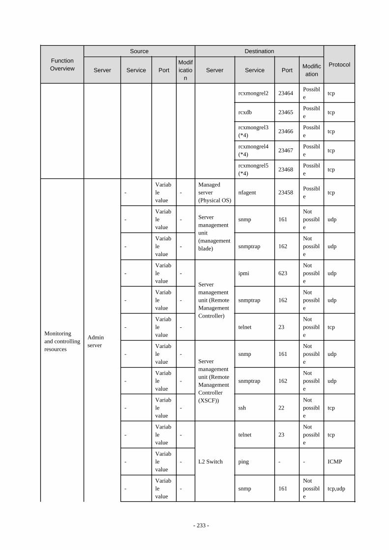
FunctionOverview
Source Destination
ProtocolServer Service Port
Modificatio
nServer Service Port
Modification
rcxmongrel2 23464Possible
tcp
rcxdb 23465Possible
tcp
rcxmongrel3(*4)
23466Possible
tcp
rcxmongrel4(*4)
23467Possible
tcp
rcxmongrel5(*4)
23468Possible
tcp
Monitoringand controllingresources
Adminserver
-Variablevalue
-Managedserver(Physical OS)
nfagent 23458Possible
tcp
-Variablevalue
- Servermanagementunit(managementblade)
snmp 161Notpossible
udp
-Variablevalue
- snmptrap 162Notpossible
udp
-Variablevalue
-
Servermanagementunit (RemoteManagementController)
ipmi 623Notpossible
udp
-Variablevalue
- snmptrap 162Notpossible
udp
-Variablevalue
- telnet 23Notpossible
tcp
-Variablevalue
-Servermanagementunit (RemoteManagementController(XSCF))
snmp 161Notpossible
udp
-Variablevalue
- snmptrap 162Notpossible
udp
-Variablevalue
- ssh 22Notpossible
tcp
-Variablevalue
-
L2 Switch
telnet 23Notpossible
tcp
-Variablevalue
- ping - - ICMP
-Variablevalue
- snmp 161Notpossible
tcp,udp
- 233 -
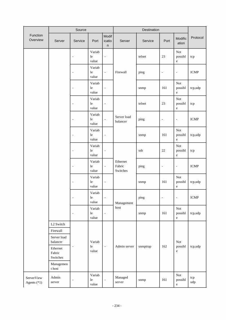
FunctionOverview
Source Destination
ProtocolServer Service Port
Modificatio
nServer Service Port
Modification
-Variablevalue
-
Firewall
telnet 23Notpossible
tcp
-Variablevalue
- ping - - ICMP
-Variablevalue
- snmp 161Notpossible
tcp,udp
-Variablevalue
-
Server loadbalancer
telnet 23Notpossible
tcp
-Variablevalue
- ping - - ICMP
-Variablevalue
- snmp 161Notpossible
tcp,udp
-Variablevalue
-
EthernetFabricSwitches
ssh 22Notpossible
tcp
-Variablevalue
- ping - - ICMP
-Variablevalue
- snmp 161Notpossible
tcp,udp
-Variablevalue
-
Managementhost
ping - - ICMP
-Variablevalue
- snmp 161Notpossible
tcp,udp
L2 Switch
-Variablevalue
- Admin server snmptrap 162Notpossible
tcp,udp
Firewall
Server loadbalancer
EthernetFabricSwitches
Management host
ServerViewAgents (*1)
Adminserver
-Variablevalue
-Managedserver
snmp 161Notpossible
tcpudp
- 234 -
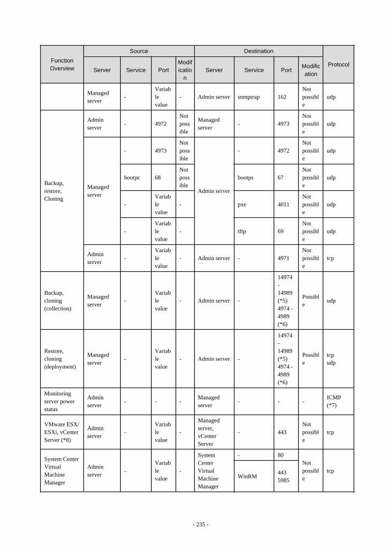
FunctionOverview
Source Destination
ProtocolServer Service Port
Modificatio
nServer Service Port
Modification
Managedserver
-Variablevalue
- Admin server snmptrap 162Notpossible
udp
Backup,restore,Cloning
Adminserver
- 4972Notpossible
Managedserver
- 4973Notpossible
udp
Managedserver
- 4973Notpossible
Admin server
- 4972Notpossible
udp
bootpc 68Notpossible
bootps 67Notpossible
udp
-Variablevalue
- pxe 4011Notpossible
udp
-Variablevalue
- tftp 69Notpossible
udp
Adminserver
-Variablevalue
- Admin server - 4971Notpossible
tcp
Backup,cloning(collection)
Managedserver
-Variablevalue
- Admin server -
14974-14989(*5)4974 -4989(*6)
Possible
udp
Restore,cloning(deployment)
Managedserver
-Variablevalue
- Admin server -
14974-14989(*5)4974 -4989(*6)
Possible
tcpudp
Monitoringserver powerstatus
Adminserver
- - -Managedserver
- - -ICMP(*7)
VMware ESX/ESXi, vCenterServer (*8)
Adminserver
-Variablevalue
-
Managedserver,vCenterServer
- 443Notpossible
tcp
System CenterVirtualMachineManager
Adminserver
-Variablevalue
-
SystemCenterVirtualMachineManager
- 80Notpossible
tcpWinRM
4435985
- 235 -
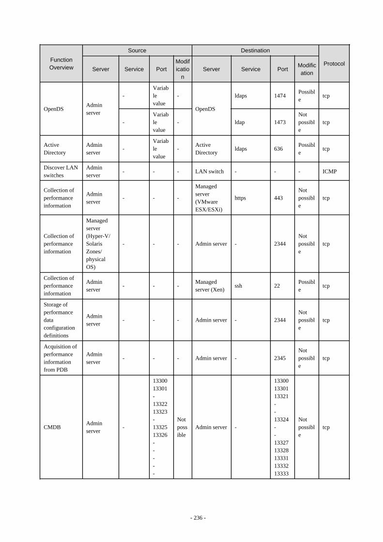
FunctionOverview
Source Destination
ProtocolServer Service Port
Modificatio
nServer Service Port
Modification
OpenDSAdminserver
-Variablevalue
-
OpenDS
ldaps 1474Possible
tcp
-Variablevalue
- ldap 1473Notpossible
tcp
ActiveDirectory
Adminserver
-Variablevalue
-ActiveDirectory
ldaps 636Possible
tcp
Discover LANswitches
Adminserver
- - - LAN switch - - - ICMP
Collection ofperformanceinformation
Adminserver
- - -
Managedserver(VMwareESX/ESXi)
https 443Notpossible
tcp
Collection ofperformanceinformation
Managedserver(Hyper-V/SolarisZones/physicalOS)
- - - Admin server - 2344Notpossible
tcp
Collection ofperformanceinformation
Adminserver
- - -Managedserver (Xen)
ssh 22Possible
tcp
Storage ofperformancedataconfigurationdefinitions
Adminserver
- - - Admin server - 2344Notpossible
tcp
Acquisition ofperformanceinformationfrom PDB
Adminserver
- - - Admin server - 2345Notpossible
tcp
CMDBAdminserver
-
1330013301-1332213323-1332513326-----
Notpossible
Admin server -
133001330113321--13324--1332713328133311333213333
Notpossible
tcp
- 236 -

FunctionOverview
Source Destination
ProtocolServer Service Port
Modificatio
nServer Service Port
Modification
InterstageBusinessProcessManagerAnalytics ruleengine
Adminserver
- - - Admin server -
[WindowsManager]40320
[LinuxManager]61320
Possible
tcp
ROR console- L-Platform- Template- TenantManagement- Request
Adminclient
-Variablevalue
Notpossible
Admin server
rcxctext 3500Notpossible
tcp
rcxctext2 3501Possible (*9)
tcp
SystemwalkerRunbookAutomationWeb console
Adminclient
-Variablevalue
Notpossible
Admin server http 80Possible (*9)
tcp
ROR CEmanagementfunction
Adminserver
-Variablevalue
Notpossible
Admin server rcxcfvsys 8013Possible (*9)
tcp
ROR CE APIAdminclient
-Variablevalue
Notpossible
Admin serverrcxcfapircxctacnt
80148015
Possible (*9)
tcp
ROR CE forinternal control
Adminserver
-Variablevalue
- Admin server rcxctrestchg 3550Notpossible
tcp
Adminserver
-Variablevalue
- Admin server rcxctint 3551Notpossible
tcp
Adminserver
-Variablevalue
- Admin server rcxctdbchg 5441Possible (*9)
tcp
Adminserver
-Variablevalue
- Admin server rcxctdbdsb 5442Notpossible
tcp
Adminserver
-Variablevalue
- Admin server CORBA 8002Possible (*9)
tcp
Adminserver
-Variablevalue
- Admin server Servlet
9available portnumbers areusedfromPort
Notpossible
tcp
- 237 -

FunctionOverview
Source Destination
ProtocolServer Service Port
Modificatio
nServer Service Port
Modification
9000/tcp
ROR CE e-mail delivery
Adminserver
-Variablevalue
- Mail server smtp 25Possible
tcp
SystemwalkerRunbookAutomation e-mail delivery
Adminserver
-Variablevalue
- Mail server smtp 25Possible
tcp
Interstagemanagementconsole
Adminclient
-Variablevalue
- Admin server http 12000Possible
tcp
Interstage JavaEE Adminconsole
Adminserver
-Variablevalue
- Admin server - 12001Possible (*10)
tcp
SystemwalkerRunbookAutomationfile transferplatform
Adminserver
-Variablevalue
- Admin server - 9664Possible
tcp
SystemwalkerRunbookAutomation forinternal control
Adminserver
-Variablevalue
- Admin server CORBA 8002Possible (*9)
tcp
Adminserver
-Variablevalue
- Admin server - 9657Notpossible
tcp
Adminserver
-Variablevalue
- Admin server - 12200Notpossible
tcp
Adminserver
-Variablevalue
- Admin server - 12210Notpossible
tcp
Adminserver
-Variablevalue
- Admin server - 18005Notpossible
tcp
Adminserver
-Variablevalue
- Admin server - 18009Notpossible
tcp
Adminserver
-Variablevalue
- Admin server - 28080Possible (*11)
tcp
Adminserver
-Variablevalue
- Admin server - 23600Possible (*12)
tcp
Adminserver
-Variablevalue
- Admin server - 23601Possible (*13)
tcp
- 238 -
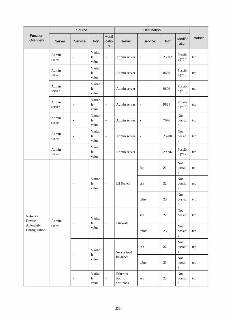
FunctionOverview
Source Destination
ProtocolServer Service Port
Modificatio
nServer Service Port
Modification
Adminserver
-Variablevalue
- Admin server - 23602Possible (*14)
tcp
Adminserver
-Variablevalue
- Admin server - 8686Possible (*15)
tcp
Adminserver
-Variablevalue
- Admin server - 9690Possible (*16)
tcp
Adminserver
-Variablevalue
- Admin server - 9691Possible (*16)
tcp
Adminserver
-Variablevalue
- Admin server - 7676Notpossible
tcp
Adminserver
-Variablevalue
- Admin server - 23700Notpossible
tcp
Adminserver
-Variablevalue
- Admin server - 29696Possible (*17)
tcp
NetworkDeviceAutomaticConfiguration
Adminserver
-Variablevalue
- L2 Switch
ftp 21Notpossible
tcp
ssh 22Notpossible
tcp
telnet 23Notpossible
tcp
-Variablevalue
- Firewall
ssh 22Notpossible
tcp
telnet 23Notpossible
tcp
-Variablevalue
-Server loadbalancer
ssh 22Notpossible
tcp
telnet 23Notpossible
tcp
-Variablevalue
-EthernetFabricSwitches
ssh 22Notpossible
tcp
- 239 -
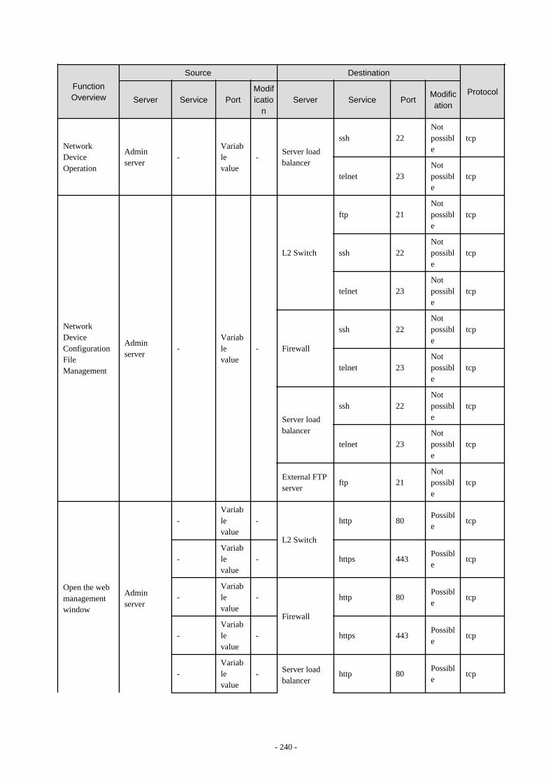
FunctionOverview
Source Destination
ProtocolServer Service Port
Modificatio
nServer Service Port
Modification
NetworkDeviceOperation
Adminserver
-Variablevalue
-Server loadbalancer
ssh 22Notpossible
tcp
telnet 23Notpossible
tcp
NetworkDeviceConfigurationFileManagement
Adminserver
-Variablevalue
-
L2 Switch
ftp 21Notpossible
tcp
ssh 22Notpossible
tcp
telnet 23Notpossible
tcp
Firewall
ssh 22Notpossible
tcp
telnet 23Notpossible
tcp
Server loadbalancer
ssh 22Notpossible
tcp
telnet 23Notpossible
tcp
External FTPserver
ftp 21Notpossible
tcp
Open the webmanagementwindow
Adminserver
-Variablevalue
-
L2 Switch
http 80Possible
tcp
-Variablevalue
- https 443Possible
tcp
-Variablevalue
-
Firewall
http 80Possible
tcp
-Variablevalue
- https 443Possible
tcp
-Variablevalue
- Server loadbalancer
http 80Possible
tcp
- 240 -
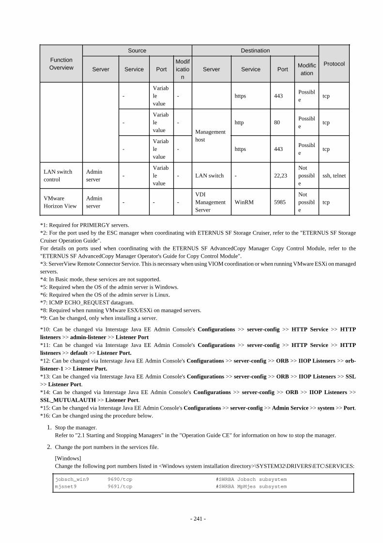
FunctionOverview
Source Destination
ProtocolServer Service Port
Modificatio
nServer Service Port
Modification
-Variablevalue
- https 443Possible
tcp
-Variablevalue
-
Managementhost
http 80Possible
tcp
-Variablevalue
- https 443Possible
tcp
LAN switchcontrol
Adminserver
-Variablevalue
- LAN switch - 22,23Notpossible
ssh, telnet
VMwareHorizon View
Adminserver
- - -VDIManagementServer
WinRM 5985Notpossible
tcp
*1: Required for PRIMERGY servers.*2: For the port used by the ESC manager when coordinating with ETERNUS SF Storage Cruiser, refer to the "ETERNUS SF StorageCruiser Operation Guide".For details on ports used when coordinating with the ETERNUS SF AdvancedCopy Manager Copy Control Module, refer to the"ETERNUS SF AdvancedCopy Manager Operator's Guide for Copy Control Module".*3: ServerView Remote Connector Service. This is necessary when using VIOM coordination or when running VMware ESXi on managedservers.*4: In Basic mode, these services are not supported.*5: Required when the OS of the admin server is Windows.*6: Required when the OS of the admin server is Linux.*7: ICMP ECHO_REQUEST datagram.*8: Required when running VMware ESX/ESXi on managed servers.*9: Can be changed, only when installing a server.
*10: Can be changed via Interstage Java EE Admin Console's Configurations >> server-config >> HTTP Service >> HTTPlisteners >> admin-listener >> Listener Port*11: Can be changed via Interstage Java EE Admin Console's Configurations >> server-config >> HTTP Service >> HTTPlisteners >> default >> Listener Port.*12: Can be changed via Interstage Java EE Admin Console's Configurations >> server-config >> ORB >> IIOP Listeners >> orb-listener-1 >> Listener Port.*13: Can be changed via Interstage Java EE Admin Console's Configurations >> server-config >> ORB >> IIOP Listeners >> SSL>> Listener Port.*14: Can be changed via Interstage Java EE Admin Console's Configurations >> server-config >> ORB >> IIOP Listeners >>SSL_MUTUALAUTH >> Listener Port.*15: Can be changed via Interstage Java EE Admin Console's Configurations >> server-config >> Admin Service >> system >> Port.*16: Can be changed using the procedure below.
1. Stop the manager.Refer to "2.1 Starting and Stopping Managers" in the "Operation Guide CE" for information on how to stop the manager.
2. Change the port numbers in the services file.
[Windows]Change the following port numbers listed in <Windows system installation directory>\SYSTEM32\DRIVERS\ETC\SERVICES:
jobsch_win9 9690/tcp #SWRBA Jobsch subsystemmjsnet9 9691/tcp #SWRBA MpMjes subsystem
- 241 -
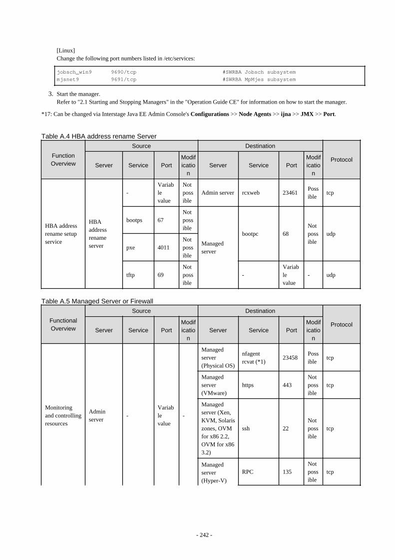
[Linux]Change the following port numbers listed in /etc/services:
jobsch_win9 9690/tcp #SWRBA Jobsch subsystemmjsnet9 9691/tcp #SWRBA MpMjes subsystem
3. Start the manager.Refer to "2.1 Starting and Stopping Managers" in the "Operation Guide CE" for information on how to start the manager.
*17: Can be changed via Interstage Java EE Admin Console's Configurations >> Node Agents >> ijna >> JMX >> Port.
Table A.4 HBA address rename Server
FunctionOverview
Source Destination
ProtocolServer Service Port
Modificatio
nServer Service Port
Modificatio
n
HBA addressrename setupservice
HBAaddressrenameserver
-Variablevalue
Notpossible
Admin server rcxweb 23461Possible
tcp
bootps 67Notpossible
Managedserver
bootpc 68Notpossible
udp
pxe 4011Notpossible
tftp 69Notpossible
-Variablevalue
- udp
Table A.5 Managed Server or Firewall
FunctionalOverview
Source Destination
ProtocolServer Service Port
Modificatio
nServer Service Port
Modificatio
n
Monitoringand controllingresources
Adminserver
-Variablevalue
-
Managedserver(Physical OS)
nfagentrcvat (*1)
23458Possible
tcp
Managedserver(VMware)
https 443Notpossible
tcp
Managedserver (Xen,KVM, Solariszones, OVMfor x86 2.2,OVM for x863.2)
ssh 22Notpossible
tcp
Managedserver(Hyper-V)
RPC 135Notpossible
tcp
- 242 -

FunctionalOverview
Source Destination
ProtocolServer Service Port
Modificatio
nServer Service Port
Modificatio
n
NETBIOSName Service
137Notpossible
tcpudp
NETBIOSDatagramService
138Notpossible
udp
NETBIOSSessionService
139Notpossible
tcp
SMB 445Notpossible
tcpudp
L2 Switch
telnet 23Notpossible
tcp
ping - - ICMP
snmp 161Notpossible
tcp,udp
Firewall
telnet 23Notpossible
tcp
ping - - ICMP
snmp 161Notpossible
tcp,udp
Server loadbalancer
telnet 23Notpossible
tcp
ping - - ICMP
snmp 161Notpossible
tcp,udp
EthernetFabricSwitches
ssh 22Notpossible
tcp
ping - - ICMP
snmp 161Notpossible
tcp,udp
Managementhost
ping - - ICMP
snmp 161Notpossible
tcp,udp
- 243 -
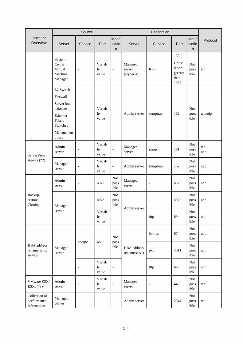
FunctionalOverview
Source Destination
ProtocolServer Service Port
Modificatio
nServer Service Port
Modificatio
n
SystemCenterVirtualMachineManager
-Variablevalue
-Managedserver(Hyper-V)
RPC
135
Unused portgreaterthan1024
Notpossible
tcp
L2 Switch
-Variablevalue
- Admin server snmptrap 162Notpossible
tcp,udp
Firewall
Server loadbalancer
EthernetFabricSwitches
Management host
ServerViewAgents (*2)
Adminserver
-Variablevalue
-Managedserver
snmp 161Notpossible
tcpudp
Managedserver
-Variablevalue
- Admin server snmptrap 162Notpossible
udp
Backup,restore,Cloning
Adminserver
- 4972Notpossible
Managedserver
- 4973Notpossible
udp
Managedserver
- 4973Notpossible
Admin server
- 4972Notpossible
udp
-Variablevalue
- tftp 69Notpossible
udp
HBA addressrename setupservice
Managedserver
bootpc 68Notpossible HBA address
rename server
bootps 67Notpossible
udp
pxe 4011Notpossible
udp
-Variablevalue
- tftp 69Notpossible
udp
VMware ESX/ESXi (*3)
Adminserver
-Variablevalue
-Managedserver
- 443Notpossible
tcp
Collection ofperformanceinformation
ManagedServer
- - - Admin server - 2344Notpossible
tcp
- 244 -
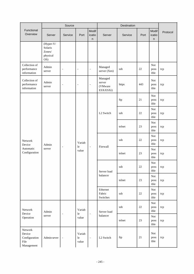
FunctionalOverview
Source Destination
ProtocolServer Service Port
Modificatio
nServer Service Port
Modificatio
n
(Hyper-V/SolarisZones/physicalOS)
Collection ofperformanceinformation
Adminserver
- - -Managedserver (Xen)
ssh 22Notpossible
tcp
Collection ofperformanceinformation
Adminserver
- - -
Managedserver(VMwareESX/ESXi)
https 443Notpossible
tcp
NetworkDeviceAutomaticConfiguration
Adminserver
-Variablevalue
-
L2 Switch
ftp 21Notpossible
tcp
ssh 22Notpossible
tcp
telnet 23Notpossible
tcp
Firewall
ssh 22Notpossible
tcp
telnet 23Notpossible
tcp
Server loadbalancer
ssh 22Notpossible
tcp
telnet 23Notpossible
tcp
EthernetFabricSwitches
ssh 22Notpossible
tcp
NetworkDeviceOperation
Adminserver
-Variablevalue
-Server loadbalancer
ssh 22Notpossible
tcp
telnet 23Notpossible
tcp
NetworkDeviceConfigurationFileManagement
Admin sever -Variablevalue
- L2 Switch ftp 21Notpossible
tcp
- 245 -
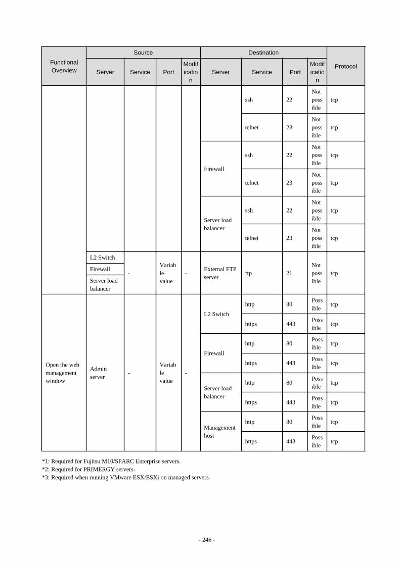
FunctionalOverview
Source Destination
ProtocolServer Service Port
Modificatio
nServer Service Port
Modificatio
n
ssh 22Notpossible
tcp
telnet 23Notpossible
tcp
Firewall
ssh 22Notpossible
tcp
telnet 23Notpossible
tcp
Server loadbalancer
ssh 22Notpossible
tcp
telnet 23Notpossible
tcp
L2 Switch
-Variablevalue
-External FTPserver
ftp 21Notpossible
tcpFirewall
Server loadbalancer
Open the webmanagementwindow
Adminserver
-Variablevalue
-
L2 Switch
http 80Possible
tcp
https 443Possible
tcp
Firewall
http 80Possible
tcp
https 443Possible
tcp
Server loadbalancer
http 80Possible
tcp
https 443Possible
tcp
Managementhost
http 80Possible
tcp
https 443Possible
tcp
*1: Required for Fujitsu M10/SPARC Enterprise servers.*2: Required for PRIMERGY servers.*3: Required when running VMware ESX/ESXi on managed servers.
- 246 -
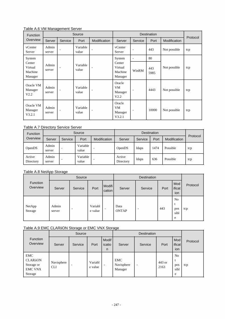
Table A.6 VM Management Server
FunctionOverview
Source DestinationProtocol
Server Service Port Modification Server Service Port Modification
vCenterServer
Adminserver
-Variablevalue
-vCenterServer
- 443 Not possible tcp
SystemCenterVirtualMachineManager
Adminserver
-Variablevalue
-
SystemCenterVirtualMachineManager
- 80
Not possible tcpWinRM
4435985
Oracle VMManagerV2.2
Adminserver
-Variablevalue
-
OracleVMManagerV2.2
- 4443 Not possible tcp
Oracle VMManagerV3.2.1
Adminserver
-Variablevalue
-
OracleVMManagerV3.2.1
- 10000 Not possible tcp
Table A.7 Directory Service Server
FunctionOverview
Source DestinationProtocol
Server Service Port Modification Server Service Port Modification
OpenDSAdminserver
-Variablevalue
- OpenDS ldaps 1474 Possible tcp
ActiveDirectory
Adminserver
-Variablevalue
-ActiveDirectory
ldaps 636 Possible tcp
Table A.8 NetApp Storage
FunctionOverview
Source Destination
ProtocolServer Service Port
Modification
Server Service PortModification
NetAppStorage
Adminserver
-Variable value
-DataONTAP
- 443
Notpossible
tcp
Table A.9 EMC CLARiiON Storage or EMC VNX Storage
FunctionOverview
Source Destination
ProtocolServer Service Port
Modificatio
nServer Service Port
Modification
EMCCLARiiONStorage orEMC VNXStorage
NavisphereCLI
-Variable value
-EMCNavisphereManager
-443 or2163
Notpossible
tcp
- 247 -
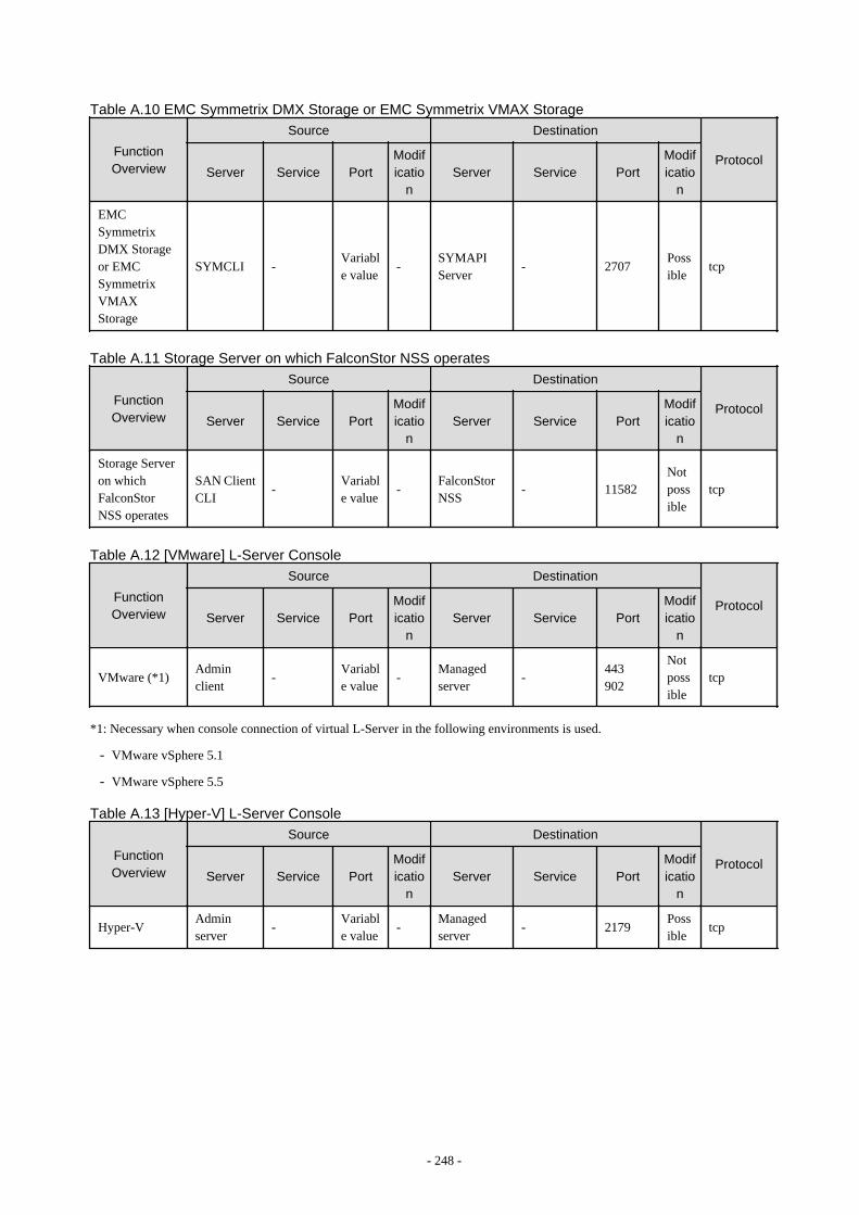
Table A.10 EMC Symmetrix DMX Storage or EMC Symmetrix VMAX Storage
FunctionOverview
Source Destination
ProtocolServer Service Port
Modificatio
nServer Service Port
Modificatio
n
EMCSymmetrixDMX Storageor EMCSymmetrixVMAXStorage
SYMCLI -Variable value
-SYMAPIServer
- 2707Possible
tcp
Table A.11 Storage Server on which FalconStor NSS operates
FunctionOverview
Source Destination
ProtocolServer Service Port
Modificatio
nServer Service Port
Modificatio
n
Storage Serveron whichFalconStorNSS operates
SAN ClientCLI
-Variable value
-FalconStorNSS
- 11582Notpossible
tcp
Table A.12 [VMware] L-Server Console
FunctionOverview
Source Destination
ProtocolServer Service Port
Modificatio
nServer Service Port
Modificatio
n
VMware (*1)Adminclient
-Variable value
-Managedserver
-443902
Notpossible
tcp
*1: Necessary when console connection of virtual L-Server in the following environments is used.
- VMware vSphere 5.1
- VMware vSphere 5.5
Table A.13 [Hyper-V] L-Server Console
FunctionOverview
Source Destination
ProtocolServer Service Port
Modificatio
nServer Service Port
Modificatio
n
Hyper-VAdminserver
-Variable value
-Managedserver
- 2179Possible
tcp
- 248 -

Table A.14 VDI Management Server
FunctionOverview
Source Destination
ProtocolServer Service Port
Modificatio
nServer Service Port
Modificatio
n
vCenter ServerVDIManagement Server
-Variable value
-vCenterServer
- 443Notpossible
tcp
ActiveDirectory
VDIManagement Server
-Variable value
-ActiveDirectory
ldaps 636Possible
tcp
- 249 -
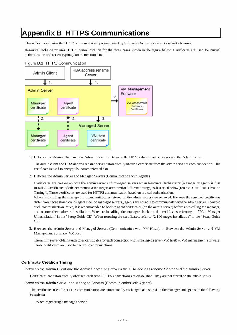
Appendix B HTTPS CommunicationsThis appendix explains the HTTPS communication protocol used by Resource Orchestrator and its security features.
Resource Orchestrator uses HTTPS communication for the three cases shown in the figure below. Certificates are used for mutualauthentication and for encrypting communication data.
Figure B.1 HTTPS Communication
1. Between the Admin Client and the Admin Server, or Between the HBA address rename Server and the Admin Server
The admin client and HBA address rename server automatically obtain a certificate from the admin server at each connection. Thiscertificate is used to encrypt the communicated data.
2. Between the Admin Server and Managed Servers (Communication with Agents)
Certificates are created on both the admin server and managed servers when Resource Orchestrator (manager or agent) is firstinstalled. Certificates of other communication targets are stored at different timings, as described below (refer to "Certificate CreationTiming"). Those certificates are used for HTTPS communication based on mutual authentication.When re-installing the manager, its agent certificates (stored on the admin server) are renewed. Because the renewed certificatesdiffer from those stored on the agent side (on managed servers), agents are not able to communicate with the admin server. To avoidsuch communication issues, it is recommended to backup agent certificates (on the admin server) before uninstalling the manager,and restore them after re-installation. When re-installing the manager, back up the certificates referring to "20.1 ManagerUninstallation" in the "Setup Guide CE". When restoring the certificates, refer to "2.1 Manager Installation" in the "Setup GuideCE".
3. Between the Admin Server and Managed Servers (Communication with VM Hosts), or Between the Admin Server and VMManagement Software [VMware]
The admin server obtains and stores certificates for each connection with a managed server (VM host) or VM management software.Those certificates are used to encrypt communications.
Certificate Creation Timing
Between the Admin Client and the Admin Server, or Between the HBA address rename Server and the Admin Server
Certificates are automatically obtained each time HTTPS connections are established. They are not stored on the admin server.
Between the Admin Server and Managed Servers (Communication with Agents)
The certificates used for HTTPS communication are automatically exchanged and stored on the manager and agents on the followingoccasions:
- When registering a managed server
- 250 -
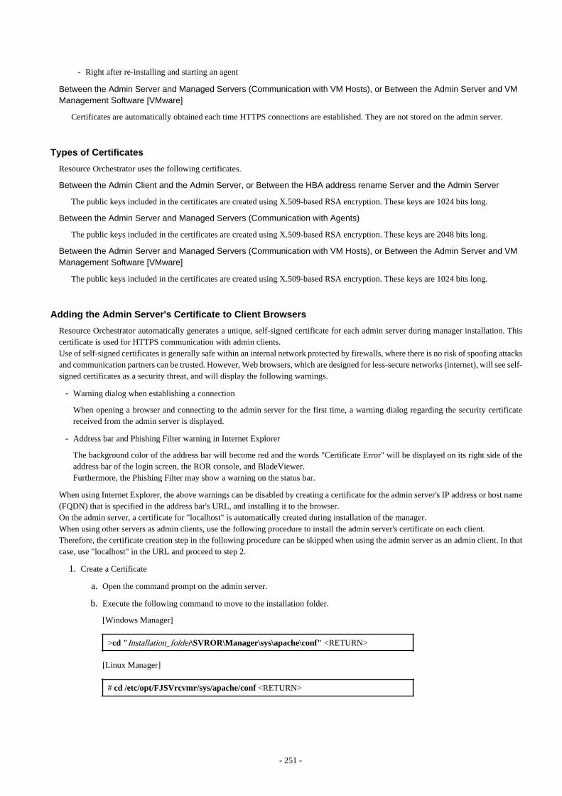
- Right after re-installing and starting an agent
Between the Admin Server and Managed Servers (Communication with VM Hosts), or Between the Admin Server and VMManagement Software [VMware]
Certificates are automatically obtained each time HTTPS connections are established. They are not stored on the admin server.
Types of Certificates
Resource Orchestrator uses the following certificates.
Between the Admin Client and the Admin Server, or Between the HBA address rename Server and the Admin Server
The public keys included in the certificates are created using X.509-based RSA encryption. These keys are 1024 bits long.
Between the Admin Server and Managed Servers (Communication with Agents)
The public keys included in the certificates are created using X.509-based RSA encryption. These keys are 2048 bits long.
Between the Admin Server and Managed Servers (Communication with VM Hosts), or Between the Admin Server and VMManagement Software [VMware]
The public keys included in the certificates are created using X.509-based RSA encryption. These keys are 1024 bits long.
Adding the Admin Server's Certificate to Client Browsers
Resource Orchestrator automatically generates a unique, self-signed certificate for each admin server during manager installation. Thiscertificate is used for HTTPS communication with admin clients.Use of self-signed certificates is generally safe within an internal network protected by firewalls, where there is no risk of spoofing attacksand communication partners can be trusted. However, Web browsers, which are designed for less-secure networks (internet), will see self-signed certificates as a security threat, and will display the following warnings.
- Warning dialog when establishing a connection
When opening a browser and connecting to the admin server for the first time, a warning dialog regarding the security certificatereceived from the admin server is displayed.
- Address bar and Phishing Filter warning in Internet Explorer
The background color of the address bar will become red and the words "Certificate Error" will be displayed on its right side of theaddress bar of the login screen, the ROR console, and BladeViewer.Furthermore, the Phishing Filter may show a warning on the status bar.
When using Internet Explorer, the above warnings can be disabled by creating a certificate for the admin server's IP address or host name(FQDN) that is specified in the address bar's URL, and installing it to the browser.On the admin server, a certificate for "localhost" is automatically created during installation of the manager.When using other servers as admin clients, use the following procedure to install the admin server's certificate on each client.Therefore, the certificate creation step in the following procedure can be skipped when using the admin server as an admin client. In thatcase, use "localhost" in the URL and proceed to step 2.
1. Create a Certificate
a. Open the command prompt on the admin server.
b. Execute the following command to move to the installation folder.
[Windows Manager]
>cd "Installation_folder\SVROR\Manager\sys\apache\conf" <RETURN>
[Linux Manager]
# cd /etc/opt/FJSVrcvmr/sys/apache/conf <RETURN>
- 251 -
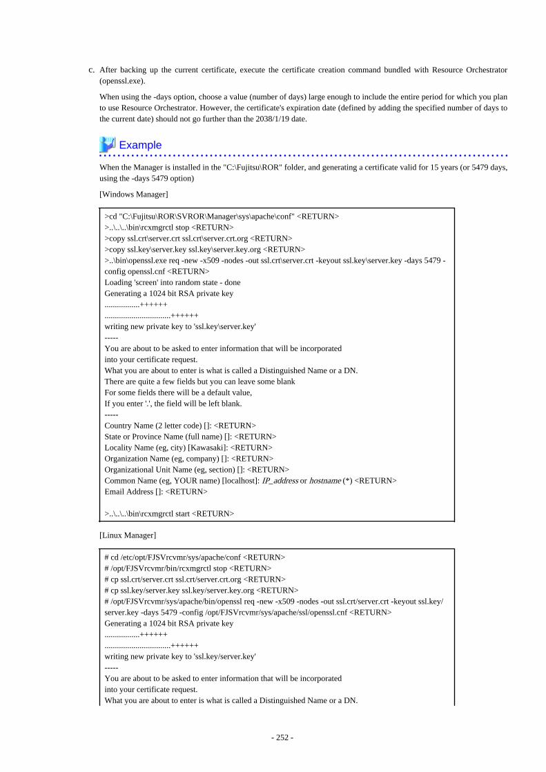
c. After backing up the current certificate, execute the certificate creation command bundled with Resource Orchestrator(openssl.exe).
When using the -days option, choose a value (number of days) large enough to include the entire period for which you planto use Resource Orchestrator. However, the certificate's expiration date (defined by adding the specified number of days tothe current date) should not go further than the 2038/1/19 date.
Example
When the Manager is installed in the "C:\Fujitsu\ROR" folder, and generating a certificate valid for 15 years (or 5479 days,using the -days 5479 option)
[Windows Manager]
>cd "C:\Fujitsu\ROR\SVROR\Manager\sys\apache\conf" <RETURN>>..\..\..\bin\rcxmgrctl stop <RETURN>>copy ssl.crt\server.crt ssl.crt\server.crt.org <RETURN>>copy ssl.key\server.key ssl.key\server.key.org <RETURN>>..\bin\openssl.exe req -new -x509 -nodes -out ssl.crt\server.crt -keyout ssl.key\server.key -days 5479 -config openssl.cnf <RETURN>Loading 'screen' into random state - doneGenerating a 1024 bit RSA private key.................++++++................................++++++writing new private key to 'ssl.key\server.key'-----You are about to be asked to enter information that will be incorporatedinto your certificate request.What you are about to enter is what is called a Distinguished Name or a DN.There are quite a few fields but you can leave some blankFor some fields there will be a default value,If you enter '.', the field will be left blank.-----Country Name (2 letter code) []: <RETURN>State or Province Name (full name) []: <RETURN>Locality Name (eg, city) [Kawasaki]: <RETURN>Organization Name (eg, company) []: <RETURN>Organizational Unit Name (eg, section) []: <RETURN>Common Name (eg, YOUR name) [localhost]: IP_address or hostname (*) <RETURN>Email Address []: <RETURN>
>..\..\..\bin\rcxmgrctl start <RETURN>
[Linux Manager]
# cd /etc/opt/FJSVrcvmr/sys/apache/conf <RETURN># /opt/FJSVrcvmr/bin/rcxmgrctl stop <RETURN># cp ssl.crt/server.crt ssl.crt/server.crt.org <RETURN># cp ssl.key/server.key ssl.key/server.key.org <RETURN># /opt/FJSVrcvmr/sys/apache/bin/openssl req -new -x509 -nodes -out ssl.crt/server.crt -keyout ssl.key/server.key -days 5479 -config /opt/FJSVrcvmr/sys/apache/ssl/openssl.cnf <RETURN>Generating a 1024 bit RSA private key.................++++++................................++++++writing new private key to 'ssl.key/server.key'-----You are about to be asked to enter information that will be incorporatedinto your certificate request.What you are about to enter is what is called a Distinguished Name or a DN.
- 252 -
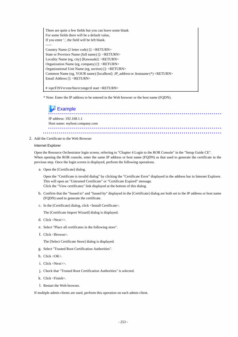
There are quite a few fields but you can leave some blankFor some fields there will be a default value,If you enter '.', the field will be left blank.-----Country Name (2 letter code) []: <RETURN>State or Province Name (full name) []: <RETURN>Locality Name (eg, city) [Kawasaki]: <RETURN>Organization Name (eg, company) []: <RETURN>Organizational Unit Name (eg, section) []: <RETURN>Common Name (eg, YOUR name) [localhost]: IP_address or hostname (*) <RETURN>Email Address []: <RETURN>
# /opt/FJSVrcvmr/bin/rcxmgrctl start <RETURN>
* Note: Enter the IP address to be entered in the Web browser or the host name (FQDN).
Example
IP address: 192.168.1.1Host name: myhost.company.com
2. Add the Certificate to the Web Browser
Internet Explorer
Open the Resource Orchestrator login screen, referring to "Chapter 4 Login to the ROR Console" in the "Setup Guide CE".When opening the ROR console, enter the same IP address or host name (FQDN) as that used to generate the certificate in theprevious step. Once the login screen is displayed, perform the following operations.
a. Open the [Certificate] dialog.
Open the "Certificate is invalid dialog" by clicking the "Certificate Error" displayed in the address bar in Internet Explorer.This will open an "Untrusted Certificate" or "Certificate Expired" message.Click the "View certificates" link displayed at the bottom of this dialog.
b. Confirm that the "Issued to" and "Issued by" displayed in the [Certificate] dialog are both set to the IP address or host name(FQDN) used to generate the certificate.
c. In the [Certificate] dialog, click <Install Certificate>.
The [Certificate Import Wizard] dialog is displayed.
d. Click <Next>>.
e. Select "Place all certificates in the following store".
f. Click <Browse>.
The [Select Certificate Store] dialog is displayed.
g. Select "Trusted Root Certification Authorities".
h. Click <OK>.
i. Click <Next>>.
j. Check that "Trusted Root Certification Authorities" is selected.
k. Click <Finish>.
l. Restart the Web browser.
If multiple admin clients are used, perform this operation on each admin client.
- 253 -
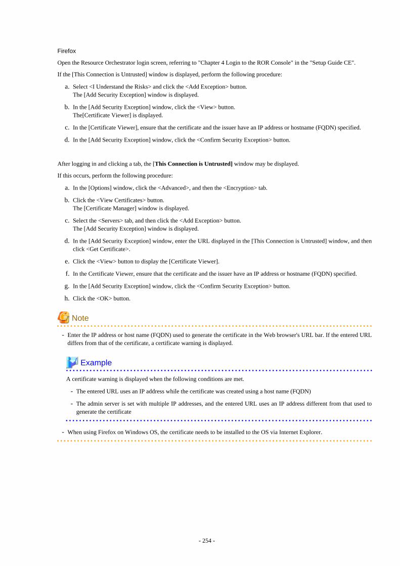
Firefox
Open the Resource Orchestrator login screen, referring to "Chapter 4 Login to the ROR Console" in the "Setup Guide CE".
If the [This Connection is Untrusted] window is displayed, perform the following procedure:
a. Select <I Understand the Risks> and click the <Add Exception> button.The [Add Security Exception] window is displayed.
b. In the [Add Security Exception] window, click the <View> button. The[Certificate Viewer] is displayed.
c. In the [Certificate Viewer], ensure that the certificate and the issuer have an IP address or hostname (FQDN) specified.
d. In the [Add Security Exception] window, click the <Confirm Security Exception> button.
After logging in and clicking a tab, the [This Connection is Untrusted] window may be displayed.
If this occurs, perform the following procedure:
a. In the [Options] window, click the <Advanced>, and then the <Encryption> tab.
b. Click the <View Certificates> button.The [Certificate Manager] window is displayed.
c. Select the <Servers> tab, and then click the <Add Exception> button.The [Add Security Exception] window is displayed.
d. In the [Add Security Exception] window, enter the URL displayed in the [This Connection is Untrusted] window, and thenclick <Get Certificate>.
e. Click the <View> button to display the [Certificate Viewer].
f. In the Certificate Viewer, ensure that the certificate and the issuer have an IP address or hostname (FQDN) specified.
g. In the [Add Security Exception] window, click the <Confirm Security Exception> button.
h. Click the <OK> button.
Note
- Enter the IP address or host name (FQDN) used to generate the certificate in the Web browser's URL bar. If the entered URLdiffers from that of the certificate, a certificate warning is displayed.
Example
A certificate warning is displayed when the following conditions are met.
- The entered URL uses an IP address while the certificate was created using a host name (FQDN)
- The admin server is set with multiple IP addresses, and the entered URL uses an IP address different from that used togenerate the certificate
- When using Firefox on Windows OS, the certificate needs to be installed to the OS via Internet Explorer.
- 254 -
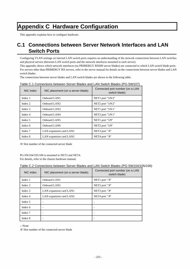
Appendix C Hardware ConfigurationThis appendix explains how to configure hardware.
C.1 Connections between Server Network Interfaces and LANSwitch Ports
Configuring VLAN settings on internal LAN switch ports requires an understanding of the network connections between LAN switchesand physical servers (between LAN switch ports and the network interfaces mounted in each server).This appendix shows which network interfaces (on PRIMERGY BX600 server blades) are connected to which LAN switch blade ports.For servers other than PRIMERGY BX servers, refer to the server manual for details on the connections between server blades and LANswitch blades.The connections between server blades and LAN switch blades are shown in the following table.
Table C.1 Connections between Server Blades and LAN Switch Blades (PG-SW107)
NIC index NIC placement (on a server blade)Connected port number (on a LAN
switch blade)
Index 1 Onboard LAN1 NET1 port "3N-2"
Index 2 Onboard LAN2 NET2 port "3N-2"
Index 3 Onboard LAN3 NET1 port "3N-1"
Index 4 Onboard LAN4 NET2 port "3N-1"
Index 5 Onboard LAN5 NET1 port "3N"
Index 6 Onboard LAN6 NET2 port "3N"
Index 7 LAN expansion card LAN1 NET3 port "N"
Index 8 LAN expansion card LAN2 NET4 port "N"
N: Slot number of the connected server blade
PG-SW104/105/106 is mounted in NET3 and NET4.For details, refer to the chassis hardware manual.
Table C.2 Connections between Server Blades and LAN Switch Blades (PG-SW104/105/106)
NIC index NIC placement (on a server blade)Connected port number (on a LAN
switch blade)
Index 1 Onboard LAN1 NET1 port "N"
Index 2 Onboard LAN2 NET2 port "N"
Index 3 LAN expansion card LAN1 NET3 port "N"
Index 4 LAN expansion card LAN2 NET4 port "N"
Index 5 - -
Index 6 - -
Index 7 - -
Index 8 - -
-: NoneN: Slot number of the connected server blade
- 255 -

Note
VLAN settings cannot be configured on the following devices.
- PRIMERGY BX600 Ethernet Blade Panel 1Gb 10/6 (IBP 10/6) and 30/12 (IBP 30/12)
- A LAN switch directly connected to a PRIMERGY BX 600 LAN pass-thru blade
- A LAN switch directly connected to servers other than PRIMERGY BX servers
LAN switch blade product names may differ between countries.This appendix refers to the product names used in Japan.The following table shows product references often used in other countries.
Reference Product Name
PG-SW104PRIMERGY BX600 Switch Blade (1Gbps)PRIMERGY BX600 Ethernet Switch 1GB 10/6(SB9)
PG-SW105PRIMERGY BX600 Switch Blade (10Gbps)PRIMERGY BX600 Ethernet Switch 1GB 10/6+2(SB9)
PG-SW106Cisco Catalyst Blade Switch 3040PRIMERGY BX600 Ethernet Switch 1GB 10/6(Cisco CBS 3040)
PG-SW107PRIMERGY BX600 Switch Blade (1Gbps)PRIMERGY BX600 Ethernet Switch 1GB 30/12(SB9F)
C.2 WWN Allocation Order during HBA address renameConfiguration
This section explains the order in which WWNs are allocated during configuration of HBA address rename.
With HBA address rename, as WWNs are allocated to the I/O addresses of HBAs in descending order, the order may not match the portorder listed in the HBA.When specifying the locations for WWN allocation, check the I/O addresses of HBAs.The I/O addresses of HBAs can be confirmed using tools provided by HBA vendors or FC-HBA BIOS.
- For blade servers
Example
For a blade server with an HBA with 2 ports, allocation is performed as follows:
WWN value provided by "I/O Virtualization Option": 20:00:00:17:42:51:00:00WWNN value for ports 1 and 2 of the HBA : 20:00:00:17:42:51:00:00WWPN value for HBA port 1 : 9:00:00 PM:17:42:51:00:00WWPN value for HBA port 2 : 10:00:00 PM:17:42:51:00:00
- For rack mount or tower servers
For the PCI slots of rack mount or tower servers, WWNs are allocated in the following order:
PRIMERGY RX200 S4 slot2 -> slot1 -> slot3PRIMERGY RX200 S5 or later slot1 -> slot2 -> slot3PRIMERGY RX300 S4 slot5 -> slot6 -> slot1 -> slot7 -> slot4 -> slot2 -> slot3PRIMERGY RX300 S5 or later slot2 -> slot3 -> slot4 -> slot5 -> slot6 -> slot7 -> slot1PRIMERGY RX600 S4 slot6 -> slot3 -> slot4 -> slot1 -> slot2 -> slot7 -> slot5PRIMERGY RX600 S5 slot7 -> slot6 -> (slot5 -> slot8 -> slot9 -> slot10) -> slot4 -> slot3 -> slot2 -> slot1PRIMERGY RX600 S6 slot7 -> slot6 -> (slot5 -> slot8 -> slot9 -> slot10) -> slot4 -> slot3 -> slot2 -> slot1
- 256 -

PRIMERGY TX300 S4 slot5 -> slot6 -> slot1 -> slot7 -> slot4 -> slot2 -> slot3PRIMERGY TX300 S5 (slot7) -> slot6 -> slot5 -> slot4 -> slot3 -> slot2 -> (slot1)PRIMERGY TX300 S6 slot5 -> slot6 -> slot1 -> slot7 -> slot4 -> slot2 -> slot3
In a single PCI slot, allocate WWNs in the following order:
port 2 -> port 1
Example
When one port HBAs are mounted in slot 2 and slot 3 of an RX600 S4, WWNs are allocated in the following order:
slot 3 -> slot 2
WWN value provided by "I/O Virtualization Option": 20:00:00:17:42:51:00:00WWNN value for slots 2 and 3 of the HBA : 20:00:00:17:42:51:00:00WWPN value for HBA slot 2 : 22:00:00:17:42:51:00:00WWPN value for HBA slot 3 : 21:00:00:17:42:51:00:00
When two port HBAs are mounted in slot 2 of an RX600 S4, WWNs are allocated in the following order:
slot 2 (port 2) -> slot 2 (port 1)
WWN value provided by "I/O Virtualization Option": 20:00:00:17:42:51:00:00WWNN value for ports 1 and 2 of the HBA : 20:00:00:17:42:51:00:00WWPN value for HBA port 1 : 10:00:00 PM:17:42:51:00:00WWPN value for HBA port 2 : 9:00:00 PM:17:42:51:00:00
C.3 Using Link AggregationThis appendix explains the procedure to use Resource Orchestrator and link aggregation at the same time. By using link aggregationbetween switches, it is possible to increase the bandwidth and reliability of the network used by L-Servers.
Figure C.1 Connection Image Using Link Aggregation
C.3.1 Configuration of Link Aggregation and a ServerThis section explains about link aggregation configuration.
Configuration for Blade Servers
Connect an external port of a LAN switch blade and an external port using link aggregation. Usually, link aggregation is not used forconnecting an internal port of a LAN switch blade and a blade server. Configure the NIC on the server in active/standby and connect.
- 257 -
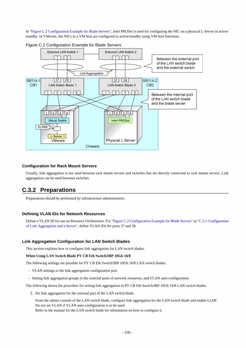
In "Figure C.2 Configuration Example for Blade Servers", Intel PROSet is used for configuring the NIC on a physical L-Server in active/standby. In VMware, the NICs in a VM host are configured in active/standby using VM host functions.
Figure C.2 Configuration Example for Blade Servers
Configuration for Rack Mount Servers
Usually, link aggregation is not used between rack mount servers and switches that are directly connected to rack mount servers. Linkaggregation can be used between switches.
C.3.2 PreparationsPreparations should be performed by infrastructure administrators.
Defining VLAN IDs for Network Resources
Define a VLAN ID for use on Resource Orchestrator. For "Figure C.2 Configuration Example for Blade Servers" in "C.3.1 Configurationof Link Aggregation and a Server", define VLAN IDs for ports 37 and 38.
Link Aggregation Configuration for LAN Switch Blades
This section explains how to configure link aggregation for LAN switch blades.
When Using LAN Switch Blade PY CB Eth Switch/IBP 10Gb 18/8
The following settings are possible for PY CB Eth Switch/IBP 10Gb 18/8 LAN switch blades.
- VLAN settings to the link aggregation configuration port
- Setting link aggregation groups in the external ports of network resources, and VLAN auto-configuration
The following shows the procedure for setting link aggregation in PY CB Eth Switch/IBP 10Gb 18/8 LAN switch blades.
1. Set link aggregation for the external port of the LAN switch blade.
From the admin console of the LAN switch blade, configure link aggregation for the LAN switch blade and enable LLDP.Do not set VLAN if VLAN auto-configuration is to be used.Refer to the manual for the LAN switch blade for information on how to configure it.
- 258 -
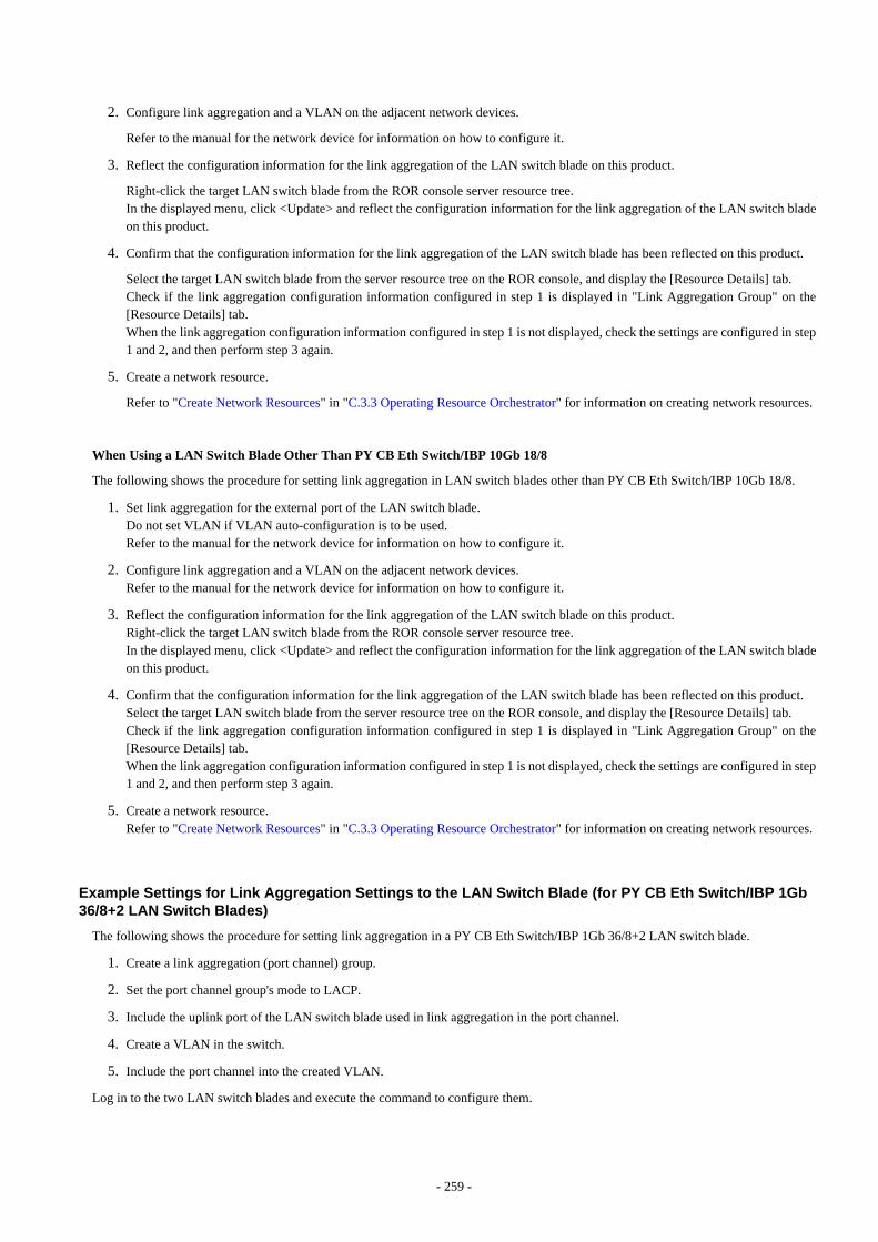
2. Configure link aggregation and a VLAN on the adjacent network devices.
Refer to the manual for the network device for information on how to configure it.
3. Reflect the configuration information for the link aggregation of the LAN switch blade on this product.
Right-click the target LAN switch blade from the ROR console server resource tree.In the displayed menu, click <Update> and reflect the configuration information for the link aggregation of the LAN switch bladeon this product.
4. Confirm that the configuration information for the link aggregation of the LAN switch blade has been reflected on this product.
Select the target LAN switch blade from the server resource tree on the ROR console, and display the [Resource Details] tab.Check if the link aggregation configuration information configured in step 1 is displayed in "Link Aggregation Group" on the[Resource Details] tab.When the link aggregation configuration information configured in step 1 is not displayed, check the settings are configured in step1 and 2, and then perform step 3 again.
5. Create a network resource.
Refer to "Create Network Resources" in "C.3.3 Operating Resource Orchestrator" for information on creating network resources.
When Using a LAN Switch Blade Other Than PY CB Eth Switch/IBP 10Gb 18/8
The following shows the procedure for setting link aggregation in LAN switch blades other than PY CB Eth Switch/IBP 10Gb 18/8.
1. Set link aggregation for the external port of the LAN switch blade.Do not set VLAN if VLAN auto-configuration is to be used.Refer to the manual for the network device for information on how to configure it.
2. Configure link aggregation and a VLAN on the adjacent network devices.Refer to the manual for the network device for information on how to configure it.
3. Reflect the configuration information for the link aggregation of the LAN switch blade on this product.Right-click the target LAN switch blade from the ROR console server resource tree.In the displayed menu, click <Update> and reflect the configuration information for the link aggregation of the LAN switch bladeon this product.
4. Confirm that the configuration information for the link aggregation of the LAN switch blade has been reflected on this product.Select the target LAN switch blade from the server resource tree on the ROR console, and display the [Resource Details] tab.Check if the link aggregation configuration information configured in step 1 is displayed in "Link Aggregation Group" on the[Resource Details] tab.When the link aggregation configuration information configured in step 1 is not displayed, check the settings are configured in step1 and 2, and then perform step 3 again.
5. Create a network resource.Refer to "Create Network Resources" in "C.3.3 Operating Resource Orchestrator" for information on creating network resources.
Example Settings for Link Aggregation Settings to the LAN Switch Blade (for PY CB Eth Switch/IBP 1Gb36/8+2 LAN Switch Blades)
The following shows the procedure for setting link aggregation in a PY CB Eth Switch/IBP 1Gb 36/8+2 LAN switch blade.
1. Create a link aggregation (port channel) group.
2. Set the port channel group's mode to LACP.
3. Include the uplink port of the LAN switch blade used in link aggregation in the port channel.
4. Create a VLAN in the switch.
5. Include the port channel into the created VLAN.
Log in to the two LAN switch blades and execute the command to configure them.
- 259 -
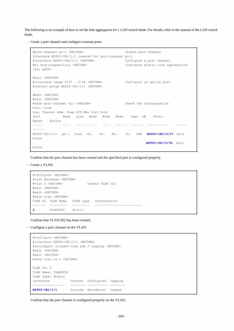
The following is an example of how to set the link aggregation for 1 LAN switch blade. For details, refer to the manual of the LAN switchblade.
- Create a port channel and configure external ports.
#port-channel pc-1 <RETURN> Create port channelInterface BX900-CB1/1/1 created for port-channel pc-1#interface BX900-CB1/1/1 <RETURN> Configure a port channel#no staticcapability <RETURN> Configure static link aggregation (for LACP)
#exit <RETURN>#interface range 0/37 - 0/38 <RETURN> Configure an uplink port#channel-group BX900-CB1/1/1 <RETURN>
#exit <RETURN>#exit <RETURN>#show port-channel all <RETURN> Check the configurationPort- LinkLog. Channel Adm. Trap STP Mbr Port PortIntf Name Link Mode Mode Mode Type LB Ports Speed Active------ ---- ------ ---- ---- ------ ------- ----------- ------ ------
BX900-CB1/1/1 pc-1 Down En. En. En. St. SDM BX900-CB1/0/37 Auto False
BX900-CB1/0/38 Auto False
Confirm that the port channel has been created and the specified port is configured properly.
- Create a VLAN
#configure <RETURN>#vlan database <RETURN>#vlan 2 <RETURN> Create VLAN ID2#exit <RETURN>#exit <RETURN>#show vlan <RETURN>VLAN ID VLAN Name VLAN Type Interface(s)------- --------- --------- -------------------------
2 VLAN0002 Static
Confirm that VLAN ID2 has been created.
- Configure a port channel on the VLAN
#configure <RETURN>#interface BX900-CB1/1/1 <RETURN>#switchport allowed vlan add 2 tagging <RETURN>#exit <RETURN>#exit <RETURN>#show vlan id 2 <RETURN>
VLAN ID: 2VLAN Name: VLAN0002VLAN Type: StaticInterface Current Configured Tagging----------------- -------- ----------- --------
BX900-CB1/1/1 Include Autodetect Tagged
Confirm that the port channel is configured properly on the VLAN.
- 260 -
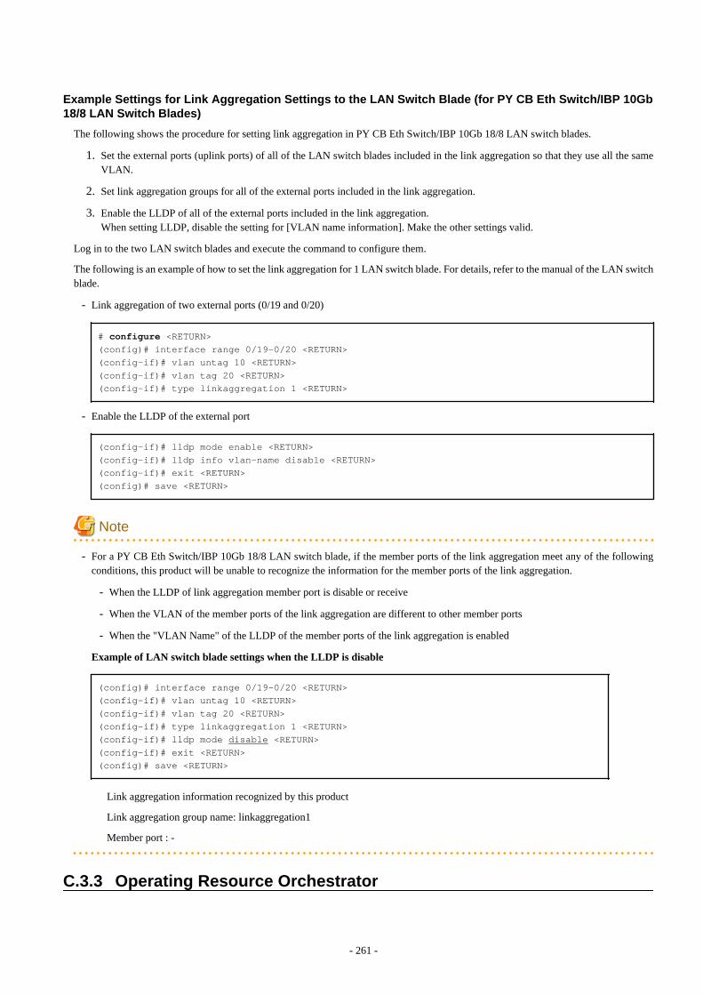
Example Settings for Link Aggregation Settings to the LAN Switch Blade (for PY CB Eth Switch/IBP 10Gb18/8 LAN Switch Blades)
The following shows the procedure for setting link aggregation in PY CB Eth Switch/IBP 10Gb 18/8 LAN switch blades.
1. Set the external ports (uplink ports) of all of the LAN switch blades included in the link aggregation so that they use all the sameVLAN.
2. Set link aggregation groups for all of the external ports included in the link aggregation.
3. Enable the LLDP of all of the external ports included in the link aggregation.When setting LLDP, disable the setting for [VLAN name information]. Make the other settings valid.
Log in to the two LAN switch blades and execute the command to configure them.
The following is an example of how to set the link aggregation for 1 LAN switch blade. For details, refer to the manual of the LAN switchblade.
- Link aggregation of two external ports (0/19 and 0/20)
# configure <RETURN>(config)# interface range 0/19-0/20 <RETURN>(config-if)# vlan untag 10 <RETURN>(config-if)# vlan tag 20 <RETURN>(config-if)# type linkaggregation 1 <RETURN>
- Enable the LLDP of the external port
(config-if)# lldp mode enable <RETURN>(config-if)# lldp info vlan-name disable <RETURN>(config-if)# exit <RETURN>(config)# save <RETURN>
Note
- For a PY CB Eth Switch/IBP 10Gb 18/8 LAN switch blade, if the member ports of the link aggregation meet any of the followingconditions, this product will be unable to recognize the information for the member ports of the link aggregation.
- When the LLDP of link aggregation member port is disable or receive
- When the VLAN of the member ports of the link aggregation are different to other member ports
- When the "VLAN Name" of the LLDP of the member ports of the link aggregation is enabled
Example of LAN switch blade settings when the LLDP is disable
(config)# interface range 0/19-0/20 <RETURN>(config-if)# vlan untag 10 <RETURN>(config-if)# vlan tag 20 <RETURN>(config-if)# type linkaggregation 1 <RETURN>(config-if)# lldp mode disable <RETURN>(config-if)# exit <RETURN>(config)# save <RETURN>
Link aggregation information recognized by this product
Link aggregation group name: linkaggregation1
Member port : -
C.3.3 Operating Resource Orchestrator
- 261 -
Create Network Resources
Network resources should be created by infrastructure administrators.
For details on parameters to configure, refer to "14.3 Network Resources" in the "User's Guide for Infrastructure Administrators (ResourceManagement) CE".
L-Server creation
L-Servers should be created by infrastructure administrators.
Specify the created network resources and create an L-Server.
Communication Checks between L-Servers and External Devices
Communication between L-Server and devices outside the chassis should be checked by tenant administrators. Enable the TCP/IP protocol.Link aggregation configuration can be used to check whether L-Servers can operate.
- 262 -

Appendix D Preparations for Creating a Physical L-ServerThis appendix explains how to perform configuration when creating a physical L-Server.
D.1 System ConfigurationThis section explains system configuration when creating a physical L-Server.
Prerequisites
To create a physical L-Server, Virtual I/O using VIOM or HBA address rename is required.For details on VIOM, refer to the ServerView Virtual-IO Manager manual.
For details on HBA address rename, refer to "5.5.2 HBA address rename Settings" in the "User's Guide for Infrastructure Administrators(Resource Management) CE".
Usage methods of VIOM and HBA address rename differ depending on the hardware of managed servers used to configure a physical L-Server.
- Blade Servers
Use VIOM.
- Rack Mount Servers
Use HBA address rename.When using rack mount servers that are supported by VIOM, the target servers are managed by VIOM.
In other cases, link L-Servers with configured physical servers. For details, refer to "Chapter 18 Linking L-Servers with ConfiguredPhysical Servers or Virtual Machines" in the "User's Guide for Infrastructure Administrators (Resource Management) CE".
Note
When using iSCSI boot, VIOM is required in the server environment.
Example of System Configuration using VIOM's Virtual I/O
An example system configuration for L-Server creation using Virtual I/O by VIOM is given below.
Install ServerView Virtual-IO Manager on the admin server.
- 263 -
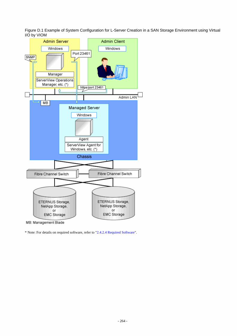
Figure D.1 Example of System Configuration for L-Server Creation in a SAN Storage Environment using VirtualI/O by VIOM
* Note: For details on required software, refer to "2.4.2.4 Required Software".
- 264 -
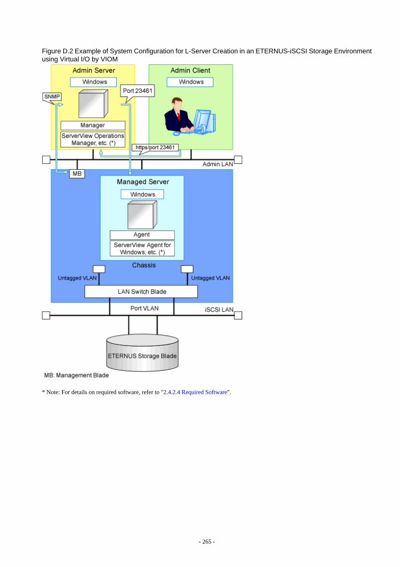
Figure D.2 Example of System Configuration for L-Server Creation in an ETERNUS-iSCSI Storage Environmentusing Virtual I/O by VIOM
* Note: For details on required software, refer to "2.4.2.4 Required Software".
- 265 -
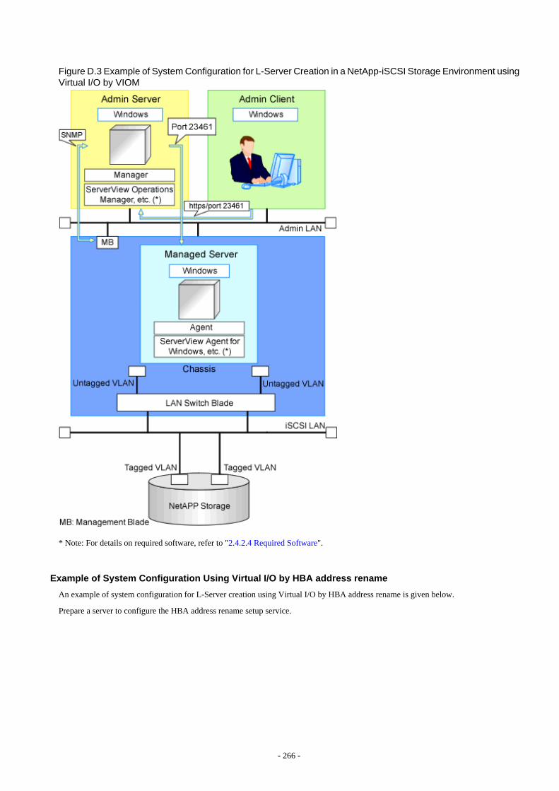
Figure D.3 Example of System Configuration for L-Server Creation in a NetApp-iSCSI Storage Environment usingVirtual I/O by VIOM
* Note: For details on required software, refer to "2.4.2.4 Required Software".
Example of System Configuration Using Virtual I/O by HBA address rename
An example of system configuration for L-Server creation using Virtual I/O by HBA address rename is given below.
Prepare a server to configure the HBA address rename setup service.
- 266 -
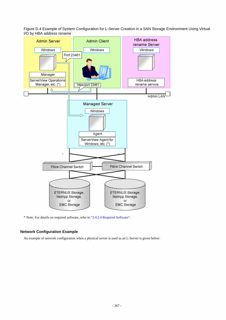
Figure D.4 Example of System Configuration for L-Server Creation in a SAN Storage Environment Using VirtualI/O by HBA address rename
* Note: For details on required software, refer to "2.4.2.4 Required Software".
Network Configuration Example
An example of network configuration when a physical server is used as an L-Server is given below:
- 267 -
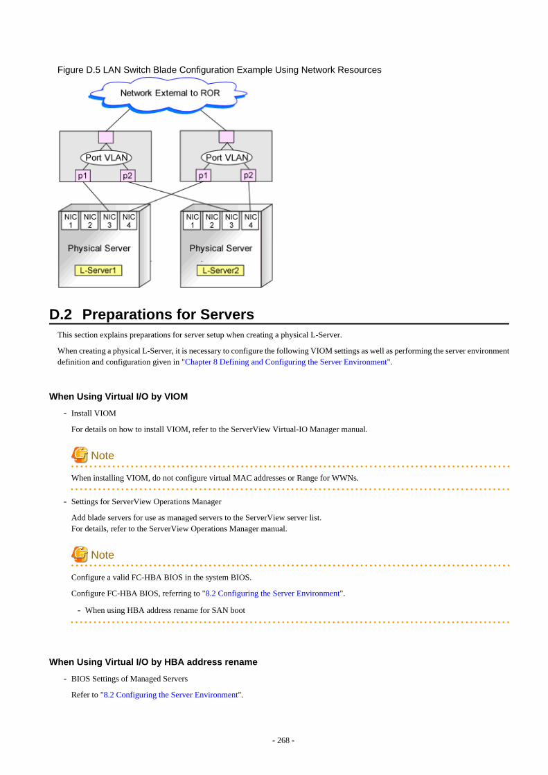
Figure D.5 LAN Switch Blade Configuration Example Using Network Resources
D.2 Preparations for ServersThis section explains preparations for server setup when creating a physical L-Server.
When creating a physical L-Server, it is necessary to configure the following VIOM settings as well as performing the server environmentdefinition and configuration given in "Chapter 8 Defining and Configuring the Server Environment".
When Using Virtual I/O by VIOM
- Install VIOM
For details on how to install VIOM, refer to the ServerView Virtual-IO Manager manual.
Note
When installing VIOM, do not configure virtual MAC addresses or Range for WWNs.
- Settings for ServerView Operations Manager
Add blade servers for use as managed servers to the ServerView server list.For details, refer to the ServerView Operations Manager manual.
Note
Configure a valid FC-HBA BIOS in the system BIOS.
Configure FC-HBA BIOS, referring to "8.2 Configuring the Server Environment".
- When using HBA address rename for SAN boot
When Using Virtual I/O by HBA address rename
- BIOS Settings of Managed Servers
Refer to "8.2 Configuring the Server Environment".
- 268 -
- When using HBA address rename for SAN boot
Configuration Using PXE Boot
When using PXE boot, the server for boot must be located and configured.
Note
PXE boot is unavailable on networks that use tagged VLAN settings.
Do not configure tagged VLANs for PXE boot servers.
D.3 Storage PreparationsThis section explains how to decide and configure a storage environment when using a physical L-Server.
D.3.1 Deciding the Storage Environment
Prerequisites for Storage when Creating a Physical L-Server
- L-Servers support SAN boot and iSCSI boot configurations.
- When using a physical server as an L-Server, it is necessary that connection using VIOM or HBA address rename is supported. Fordetails on connection using VIOM or HBA address rename, refer to "10.1 Deciding the Storage Environment" and "10.2 Configuringthe Storage Environment".
- Usage methods of VIOM and HBA address rename differ depending on the hardware of managed servers used to configure a physicalL-Server.
- Blade Servers
Use VIOM.
- Rack Mount Servers
Use HBA address rename.When using rack mount servers that are supported by VIOM, the target servers are managed by VIOM.
- For L-Server SAN storage paths and iSCSI storage paths, multipaths (two paths) are supported.
- Configurations with two or less HBA ports on managed servers are supported.
- When using the MMB firmware for which Fibre Channel card information cannot be obtained by blade servers, only configurationswhere Fibre Channel cards are mounted in expansion slot 2 are supported. The servers for which the information of Fibre Channelcards can be obtained are as follows:
- PRIMERGY BX900 series servers
4.70 or later
- PRIMERGY BX400 series servers
6.22 or later
- When setting up VIOM, do not configure the following items.
- WWN Address Range
- MAC Address Range
Regarding Storage Configuration
Decide the storage configuration necessary for the system.
- 269 -
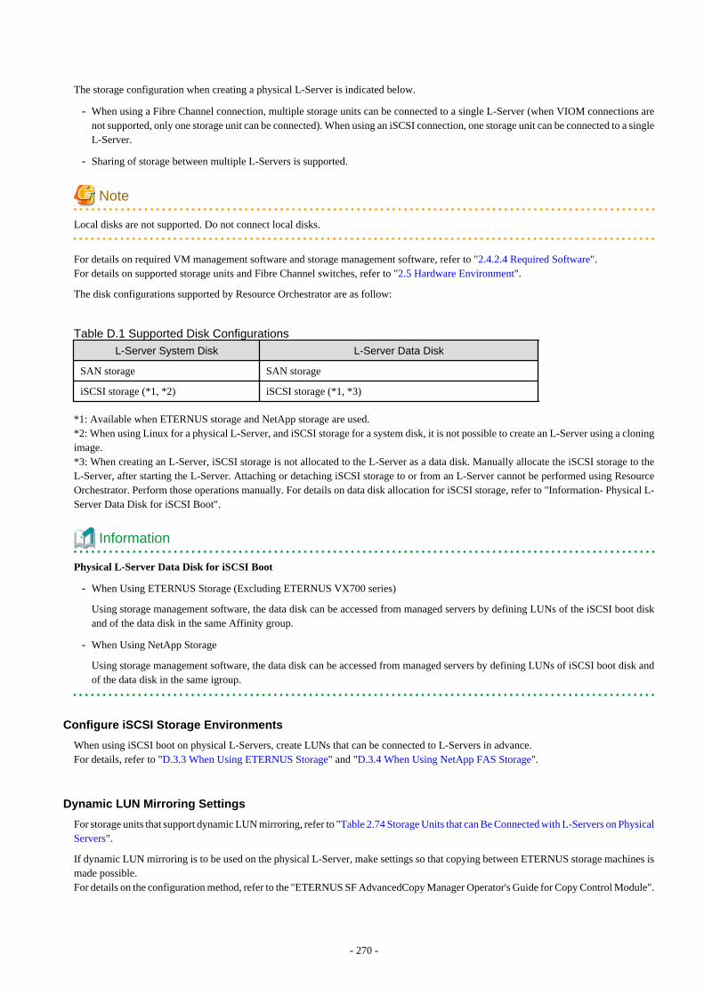
The storage configuration when creating a physical L-Server is indicated below.
- When using a Fibre Channel connection, multiple storage units can be connected to a single L-Server (when VIOM connections arenot supported, only one storage unit can be connected). When using an iSCSI connection, one storage unit can be connected to a singleL-Server.
- Sharing of storage between multiple L-Servers is supported.
Note
Local disks are not supported. Do not connect local disks.
For details on required VM management software and storage management software, refer to "2.4.2.4 Required Software".For details on supported storage units and Fibre Channel switches, refer to "2.5 Hardware Environment".
The disk configurations supported by Resource Orchestrator are as follow:
Table D.1 Supported Disk Configurations
L-Server System Disk L-Server Data Disk
SAN storage SAN storage
iSCSI storage (*1, *2) iSCSI storage (*1, *3)
*1: Available when ETERNUS storage and NetApp storage are used.*2: When using Linux for a physical L-Server, and iSCSI storage for a system disk, it is not possible to create an L-Server using a cloningimage.*3: When creating an L-Server, iSCSI storage is not allocated to the L-Server as a data disk. Manually allocate the iSCSI storage to theL-Server, after starting the L-Server. Attaching or detaching iSCSI storage to or from an L-Server cannot be performed using ResourceOrchestrator. Perform those operations manually. For details on data disk allocation for iSCSI storage, refer to "Information- Physical L-Server Data Disk for iSCSI Boot".
Information
Physical L-Server Data Disk for iSCSI Boot
- When Using ETERNUS Storage (Excluding ETERNUS VX700 series)
Using storage management software, the data disk can be accessed from managed servers by defining LUNs of the iSCSI boot diskand of the data disk in the same Affinity group.
- When Using NetApp Storage
Using storage management software, the data disk can be accessed from managed servers by defining LUNs of iSCSI boot disk andof the data disk in the same igroup.
Configure iSCSI Storage Environments
When using iSCSI boot on physical L-Servers, create LUNs that can be connected to L-Servers in advance.For details, refer to "D.3.3 When Using ETERNUS Storage" and "D.3.4 When Using NetApp FAS Storage".
Dynamic LUN Mirroring Settings
For storage units that support dynamic LUN mirroring, refer to "Table 2.74 Storage Units that can Be Connected with L-Servers on PhysicalServers".
If dynamic LUN mirroring is to be used on the physical L-Server, make settings so that copying between ETERNUS storage machines ismade possible.For details on the configuration method, refer to the "ETERNUS SF AdvancedCopy Manager Operator's Guide for Copy Control Module".
- 270 -
D.3.2 Preparations for Storage EnvironmentsThe settings necessary when using storage environments are performed using the following flow.
1. Storage Unit Configuration
- When using ETERNUS storage
Refer to "ETERNUS Storage Configuration" of "D.3.3 When Using ETERNUS Storage".
- When using NetApp FAS series/V series
Refer to "NetApp FAS Storage Configuration" of "D.3.4 When Using NetApp FAS Storage".
- When using EMC CLARiiON storage or EMC VNX Storage
Refer to "D.3.5 When Using EMC CLARiiON Storage or EMC VNX Storage" of "EMC CLARiiON Storage or EMC VNXStorage Configuration".
- When using EMC Symmetrix DMX storage or EMC Symmetrix VMAX storage
Refer to "Configuration of EMC Symmetrix DMX Storage or EMC Symmetrix VMAX Storage" of "D.3.6 When Using EMCSymmetrix DMX Storage or EMC Symmetrix VMAX Storage".
- When using Storage Server on which FalconStor NSS operates
Refer to "Configuration of Storage Server on which FalconStor NSS Operates" of "D.3.7 When Using Storage Server on whichFalconStor NSS Operates".
2. Fibre Channel Switch Configuration
- When connecting ETERNUS storage to fibre channel switches
Refer to "When Connecting ETERNUS Storage to Fibre Channel Switches" of "D.3.3 When Using ETERNUS Storage".
- When connecting NetApp storage to fibre channel switches
Refer to "When Connecting NetApp Storage to Fibre Channel Switches" of "D.3.4 When Using NetApp FAS Storage".
- When connecting EMC Symmetrix DMX storage or EMC Symmetrix VMAX storage with fibre channel switches
Refer to "When Connecting EMC CLARiiON Storage or EMC VNX Storage to Fibre Channel Switches" of "EMC CLARiiONStorage or EMC VNX Storage Configuration".
- When Connecting EMC Symmetrix DMX Storage or EMC Symmetrix VMAX Storage to Fibre Channel Switches
Refer to "When Connecting EMC Symmetrix DMX Storage or EMC Symmetrix VMAX Storage to Fibre Channel Switches"of "D.3.6 When Using EMC Symmetrix DMX Storage or EMC Symmetrix VMAX Storage".
- When connecting Storage Server on which FalconStor NSS operates
Refer to "When Connecting the Storage Server on which FalconStor NSS Operates to Fibre Channel Switches" of "D.3.7 WhenUsing Storage Server on which FalconStor NSS Operates".
D.3.3 When Using ETERNUS StorageThis section explains how to configure ETERNUS storage.
ETERNUS Storage Configuration
Resource Orchestrator manages only ETERNUS registered on ESC. Register the target ETERNUS on ESC.
For details on how to register to ESC, refer to the "ETERNUS SF Storage Cruiser Operation Guide".
URL: http://software.fujitsu.com/jp/manual/manualindex/p13000447e.html
- 271 -

Note
- Definition of ETERNUS hot spares, RAID groups, and TPP is not possible in Resource Orchestrator. Predefine hot spares, RAIDgroups, and TPP using ETERNUSmgr or other software.
- Resource Orchestrator supports access path settings on the FC-CA ports of ETERNUS connected using Fabric connections. It isnecessary to select "Fabric connection" in the settings of the connection method of ETERNUS FC-CA ports.
- Resource Orchestrator uses ETERNUS host affinity to enable recognition of LUNs by servers. Therefore, for affinity mode settingsof ETERNUS FC-CA ports, "ON" must be selected.
When Connecting ETERNUS Storage to Fibre Channel Switches
When creating a disk from an ETERNUS RAID group, configure one-to-one WWPN zoning for the Fibre Channel switch registered onESC. Therefore, it is necessary to register the Fibre Channel switch connected to ETERNUS and all Fibre Channel switches connected toit using a cascade connection on ESC.
For details on how to register to ESC, refer to the "ETERNUS SF Storage Cruiser Operation Guide".
Zoning settings may not have been configured for Fibre Channel switches. When zoning is not configured, ensure that temporary zoningis configured, since there is a chance that one-to-one WWPN zoning settings cannot be configured. For details on how to performconfiguration, refer to the ESC manual.
When Using ETERNUS Storage for iSCSI Boot
Define the following using storage management software. Regarding the defined information, register a disk on a resource, using theoperation command (rcxadm iscsictl) for iSCSI boot.
- Creation of the LUN used by iSCSI boot. Settings to permit access to the LUN from the server.
Note
If iSCSI boot information already registered is specified, the registered information continues to exist.
If the registered information is changed, delete the iSCSI boot information using the unregister subcommand, and then register the iSCSIboot information by using the register subcommand again.
The definition information registered using the operation command (rcxadm iscsictl) for iSCSI boot is as follows:
For details, refer to "15.4.2 iSCSI Boot Information" in the "Reference Guide (Command/XML) CE".
- Storage Information
IP address of the storage port used for iSCSI
Storage port IQN name used for iSCSI
- Server Information
IP address of the server used for iSCSI
Server IQN name used for iSCSI
- Disk Information
LUN disk size used for iSCSI boot
- Authentication Information for iSCSI
When using dynamic LUN mirroring
When using dynamic LUN mirroring, copying chassis is possible through coordination with CCM.
- 272 -
When using this function, make settings so that copying between ETERNUS storage chassis is possible.
For details on the configuration method, refer to the "ETERNUS SF AdvancedCopy Manager Operator's Guide for Copy Control Module".
D.3.4 When Using NetApp FAS StorageThis section explains how to configure NetApp storage.
NetApp FAS Storage Configuration
- For Fibre Channel Connections
Use the following procedure to configure NetApp FAS series/V series settings:
1. Initial Configuration
Set the password of the Data ONTAP root account (using more than one character) and the admin IP address of Data ONTAP,referring to the "Data ONTAP Software Setup Guide" manual.
Note
- Resource Orchestrator uses the NetApp FAS series/V series which is not registered on storage management software suchas DataFabric Manager.
- Only one admin IP address can be registered for the NetApp FAS series/ V series on Resource Orchestrator.
2. Configuration of SSL
Configure SSL, referring to the "Data ONTAP System Administration Guide" manual.
For Data ONTAP7.3, execute the following command on the Data ONTAP that is to be managed:
>secureadmin setup ssl <RETURN>>options tls.enable on <RETURN>>secureadmin enable ssl <RETURN>
3. Creation of Aggregates
Create more than one aggregate, referring to the "Data ONTAP Storage Management Guide" manual.
Set any desired number when subdividing the management, such as when managing by users.
Aggregates can be added later.
4. Fibre Channel Connection Environment Settings
Configure the following settings, referring to the "Data ONTAP Block Access Management Guide for iSCSI and FC" manual.
- Configure the license settings of the Fibre Channel service.
- Confirm the port settings, and configure the FC port for connection with the managed server as the target port.
5. Creation of portset
Refer to the "Data ONTAP Block Access Management Guide for iSCSI and FC" manual, and create one or more portsets thatcombine FC ports used for access to the L-Server disk.
Up to two port numbers can be set up per portset.
When using NetApp storage with multiple controllers, create it combining the FC ports of the different controllers.
Use the following name for the portset name:
rcx-portsetNN (*)
* Note: For NN, specify a number from 00 - 99
- 273 -
Note
- For the FC port to register in a portset, specify an FC port that is not registered in another portset.
- Specify the FC port the Fibre Channel cable was connected to.
- No portset other than the rcx-portsetNN is used.
- For iSCSI Connections
Perform the following operations referring to the "Data ONTAP Block Access Management Guide for iSCSI and FC":
- Creation of LUNs to connect to L-Servers
- Confirmation of storage information to register using the operation command for iSCSI boot (rcxadm iscsictl)
The main definition information is as follows:
For details, refer to "15.4.2 iSCSI Boot Information" in the "Reference Guide (Command/XML) CE".
- Storage Information
IP address of the storage port used for iSCSI
Storage port IQN name used for iSCSI
- Server Information
IP address of the server used for iSCSI
Server IQN name used for iSCSI
- Disk Information
LUN disk size used for iSCSI boot
- Authentication Information for iSCSI
Note
- Disks with iSCSI boot information registered may be detected as resources of registered storage management software.
Do not use the disks for iSCSI boot as the LUNs created in advance.
- If iSCSI boot information already registered is specified, the registered information continues to exist.
If the registered information is changed, delete the iSCSI boot information using the unregister subcommand, and then registerthe iSCSI boot information by using the register subcommand again.
When Connecting NetApp Storage to Fibre Channel Switches
In Resource Orchestrator, when creating disks from NetApp aggregates, configuration of Fibre Channel switches connected to NetApp isnot performed.
It is necessary to configure one-to-one WWPN zoning for Fibre Channel switches in advance.
It is necessary to define zoning combining the fibre channel switch combining the HBA Port WWPN value based on the WWN providedby the I/O Virtualization Option and the FC port WWPN value defined in the NetApp portset used in Resource Orchestrator. For detailson the configuration method, refer to the manual of the fibre channel switch.
Fibre Channel Switch Zoning Settings
Set zoning combining the WWPN value of HBA Port1 and the WWPN value of defined FC port first in portset, and combining the WWPNvalue of HBA Port2 and the WWPN value of defined FC port second in portset.
- 274 -
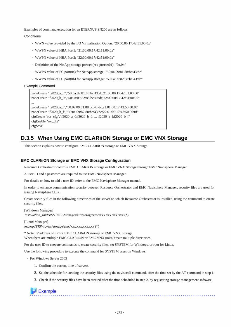
Examples of command execution for an ETERNUS SN200 are as follows:
Conditions
- WWN value provided by the I/O Virtualization Option: "20:00:00:17:42:51:00:0x"
- WWPN value of HBA Port1: "21:00:00:17:42:51:00:0x"
- WWPN value of HBA Port2: "22:00:00:17:42:51:00:0x"
- Definition of the NetApp storage portset (rcx-portset01): "0a,0b"
- WWPN value of FC port(0a) for NetApp storage: "50:0a:09:81:88:bc:43:dc"
- WWPN value of FC port(0b) for NetApp storage: "50:0a:09:82:88:bc:43:dc"
Example Command
zoneCreate "f2020_a_0","50:0a:09:81:88:bc:43:dc;21:00:00:17:42:51:00:00"zoneCreate "f2020_b_0","50:0a:09:82:88:bc:43:dc;22:00:00:17:42:51:00:00"...zoneCreate "f2020_a_f","50:0a:09:81:88:bc:43:dc;21:01:00:17:43:50:00:0f"zoneCreate "f2020_b_f","50:0a:09:82:88:bc:43:dc;22:01:00:17:43:50:00:0f"cfgCreate "ror_cfg","f2020_a_0;f2020_b_0; ... ;f2020_a_f;f2020_b_f"cfgEnable "ror_cfg"cfgSave
D.3.5 When Using EMC CLARiiON Storage or EMC VNX StorageThis section explains how to configure EMC CLARiiON storage or EMC VNX Storage.
EMC CLARiiON Storage or EMC VNX Storage Configuration
Resource Orchestrator controls EMC CLARiiON storage or EMC VNX Storage through EMC Navisphere Manager.
A user ID and a password are required to use EMC Navisphere Manager.
For details on how to add a user ID, refer to the EMC Navisphere Manager manual.
In order to enhance communication security between Resource Orchestrator and EMC Navisphere Manager, security files are used forissuing Navisphere CLIs.
Create security files in the following directories of the server on which Resource Orchestrator is installed, using the command to createsecurity files.
[Windows Manager]Installation_folder\SVROR\Manager\etc\storage\emc\xxx.xxx.xxx.xxx (*)
[Linux Manager]/etc/opt/FJSVrcvmr/storage/emc/xxx.xxx.xxx.xxx (*)
* Note: IP address of SP for EMC CLARiiON storage or EMC VNX Storage.When there are multiple EMC CLARiiON or EMC VNX units, create multiple directories.
For the user ID to execute commands to create security files, set SYSTEM for Windows, or root for Linux.
Use the following procedure to execute the command for SYSTEM users on Windows.
- For Windows Server 2003
1. Confirm the current time of servers.
2. Set the schedule for creating the security files using the naviseccli command, after the time set by the AT command in step 1.
3. Check if the security files have been created after the time scheduled in step 2, by registering storage management software.
Example
- 275 -
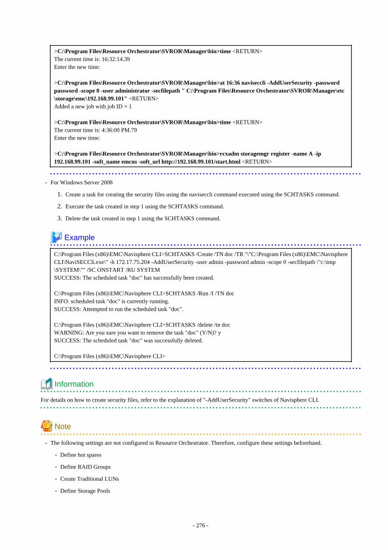
>C:\Program Files\Resource Orchestrator\SVROR\Manager\bin>time <RETURN>The current time is: 16:32:14.39Enter the new time:
>C:\Program Files\Resource Orchestrator\SVROR\Manager\bin>at 16:36 naviseccli -AddUserSecurity -passwordpassword -scope 0 -user administrator -secfilepath " C:\Program Files\Resource Orchestrator\SVROR\Manager\etc\storage\emc\192.168.99.101" <RETURN>Added a new job with job ID = 1
>C:\Program Files\Resource Orchestrator\SVROR\Manager\bin>time <RETURN>The current time is: 4:36:00 PM.79Enter the new time:
>C:\Program Files\Resource Orchestrator\SVROR\Manager\bin>rcxadm storagemgr register -name A -ip192.168.99.101 -soft_name emcns -soft_url http://192.168.99.101/start.html <RETURN>
- For Windows Server 2008
1. Create a task for creating the security files using the naviseccli command executed using the SCHTASKS command.
2. Execute the task created in step 1 using the SCHTASKS command.
3. Delete the task created in step 1 using the SCHTASKS command.
Example
C:\Program Files (x86)\EMC\Navisphere CLI>SCHTASKS /Create /TN doc /TR "\"C:\Program Files (x86)\EMC\NavisphereCLI\NaviSECCli.exe\" -h 172.17.75.204 -AddUserSecurity -user admin -password admin -scope 0 -secfilepath \"c:\tmp\SYSTEM\"" /SC ONSTART /RU SYSTEMSUCCESS: The scheduled task "doc" has successfully been created.
C:\Program Files (x86)\EMC\Navisphere CLI>SCHTASKS /Run /I /TN docINFO: scheduled task "doc" is currently running.SUCCESS: Attempted to run the scheduled task "doc".
C:\Program Files (x86)\EMC\Navisphere CLI>SCHTASKS /delete /tn docWARNING: Are you sure you want to remove the task "doc" (Y/N)? ySUCCESS: The scheduled task "doc" was successfully deleted.
C:\Program Files (x86)\EMC\Navisphere CLI>
Information
For details on how to create security files, refer to the explanation of "-AddUserSecurity" switches of Navisphere CLI.
Note
- The following settings are not configured in Resource Orchestrator. Therefore, configure these settings beforehand.
- Define hot spares
- Define RAID Groups
- Create Traditional LUNs
- Define Storage Pools
- 276 -
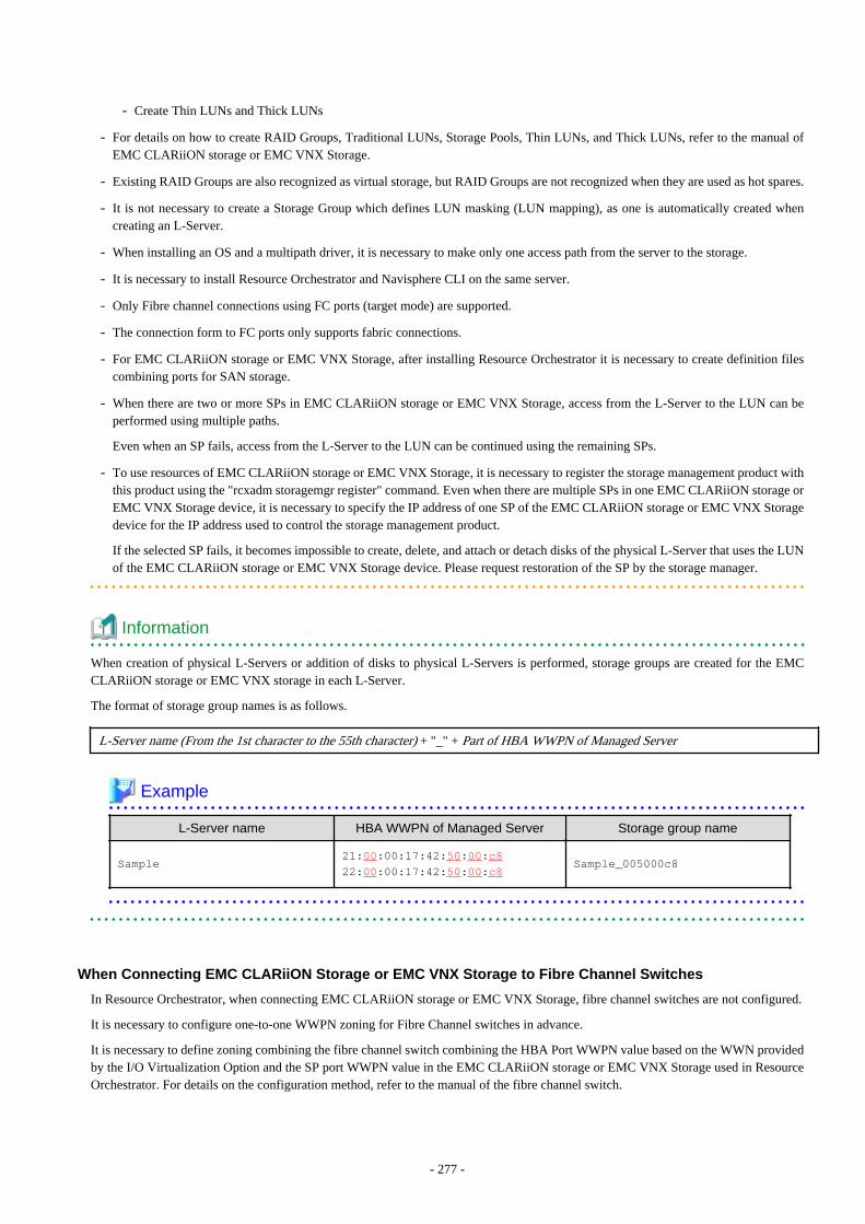
- Create Thin LUNs and Thick LUNs
- For details on how to create RAID Groups, Traditional LUNs, Storage Pools, Thin LUNs, and Thick LUNs, refer to the manual ofEMC CLARiiON storage or EMC VNX Storage.
- Existing RAID Groups are also recognized as virtual storage, but RAID Groups are not recognized when they are used as hot spares.
- It is not necessary to create a Storage Group which defines LUN masking (LUN mapping), as one is automatically created whencreating an L-Server.
- When installing an OS and a multipath driver, it is necessary to make only one access path from the server to the storage.
- It is necessary to install Resource Orchestrator and Navisphere CLI on the same server.
- Only Fibre channel connections using FC ports (target mode) are supported.
- The connection form to FC ports only supports fabric connections.
- For EMC CLARiiON storage or EMC VNX Storage, after installing Resource Orchestrator it is necessary to create definition filescombining ports for SAN storage.
- When there are two or more SPs in EMC CLARiiON storage or EMC VNX Storage, access from the L-Server to the LUN can beperformed using multiple paths.
Even when an SP fails, access from the L-Server to the LUN can be continued using the remaining SPs.
- To use resources of EMC CLARiiON storage or EMC VNX Storage, it is necessary to register the storage management product withthis product using the "rcxadm storagemgr register" command. Even when there are multiple SPs in one EMC CLARiiON storage orEMC VNX Storage device, it is necessary to specify the IP address of one SP of the EMC CLARiiON storage or EMC VNX Storagedevice for the IP address used to control the storage management product.
If the selected SP fails, it becomes impossible to create, delete, and attach or detach disks of the physical L-Server that uses the LUNof the EMC CLARiiON storage or EMC VNX Storage device. Please request restoration of the SP by the storage manager.
Information
When creation of physical L-Servers or addition of disks to physical L-Servers is performed, storage groups are created for the EMCCLARiiON storage or EMC VNX storage in each L-Server.
The format of storage group names is as follows.
L-Server name (From the 1st character to the 55th character) + "_" + Part of HBA WWPN of Managed Server
Example
L-Server name HBA WWPN of Managed Server Storage group name
Sample21:00:00:17:42:50:00:c822:00:00:17:42:50:00:c8
Sample_005000c8
When Connecting EMC CLARiiON Storage or EMC VNX Storage to Fibre Channel Switches
In Resource Orchestrator, when connecting EMC CLARiiON storage or EMC VNX Storage, fibre channel switches are not configured.
It is necessary to configure one-to-one WWPN zoning for Fibre Channel switches in advance.
It is necessary to define zoning combining the fibre channel switch combining the HBA Port WWPN value based on the WWN providedby the I/O Virtualization Option and the SP port WWPN value in the EMC CLARiiON storage or EMC VNX Storage used in ResourceOrchestrator. For details on the configuration method, refer to the manual of the fibre channel switch.
- 277 -

Fibre Channel Switch Zoning Settings
Set zoning combining the WWPN value of HBA Port1 and the WWPN value of the first SP port defined in the storage_portset.rcxpropdefinition file, and combining the WWPN value of HBA Port2 and the WWPN value of the second SP port defined in portset.
Examples of command execution for an ETERNUS SN200 are as follows:
In the following examples, 64 patterns of zoning are performed using combination of 16 WWN and 4 SP ports.
Example
Conditions
- WWN value provided by the I/O Virtualization Option
"20:00:00:17:42:51:00:0x"
- WWPN value of HBA Port1
"9:00:00 PM:17:42:51:00:0x"
- WWPN value of HBA Port2
"10:00:00 PM:17:42:51:00:0x"
- Content of the definition file "storage_portset.rcxprop"
192.168.1.24,"SPAPort0:SPBPort0","SPAPort1:SPBPort1"
- WWPN value of SP port "SPAPort0"
"50:0a:09:81:88:bc:43:dc"
- WWPN value of SP port "SPBPort0"
"50:0a:09:82:88:bc:43:dc"
- WWPN value of SP port "SPAPort1"
"50:0a:09:83:88:bc:43:dc"
- WWPN value of SP port "SPBPort1"
"50:0a:09:84:88:bc:43:dc"
zoneCreate "emc_a_0","50:0a:09:81:88:bc:43:dc;21:00:00:17:42:51:00:00" <RETURN>zoneCreate "emc_b_0","50:0a:09:82:88:bc:43:dc;22:00:00:17:42:51:00:00" <RETURN>...zoneCreate "emc_a_f","50:0a:09:81:88:bc:43:dc;21:01:00:17:42:50:00:0f" <RETURN>zoneCreate "emc_b_f","50:0a:09:82:88:bc:43:dc;22:01:00:17:42:50:00:0f" <RETURN>zoneCreate "emc_c_0","50:0a:09:83:88:bc:43:dc;21:00:00:17:42:51:00:00" <RETURN>zoneCreate "emc_d_0","50:0a:09:84:88:bc:43:dc;22:00:00:17:42:51:00:00" <RETURN>...zoneCreate "emc_c_f","50:0a:09:83:88:bc:43:dc;21:01:00:17:42:50:00:0f" <RETURN>zoneCreate "emc_d_f","50:0a:09:84:88:bc:43:dc;22:01:00:17:42:50:00:0f" <RETURN>cfgCreate "ror_cfg","emc_a_0;emc_b_0; ... ;emc_a_f;emc_b_f;emc_c_0;emc_d_0; ... ;emc_c_f;emc_d_f" <RETURN>cfgEnable "ror_cfg" <RETURN>cfgSave <RETURN>
D.3.6 When Using EMC Symmetrix DMX Storage or EMC Symmetrix VMAXStorage
This section explains how to configure EMC Symmetrix DMX storage and EMC Symmetrix VMAX storage.
- 278 -
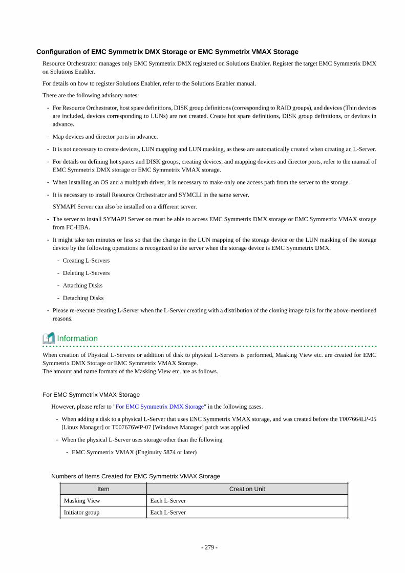
Configuration of EMC Symmetrix DMX Storage or EMC Symmetrix VMAX Storage
Resource Orchestrator manages only EMC Symmetrix DMX registered on Solutions Enabler. Register the target EMC Symmetrix DMXon Solutions Enabler.
For details on how to register Solutions Enabler, refer to the Solutions Enabler manual.
There are the following advisory notes:
- For Resource Orchestrator, host spare definitions, DISK group definitions (corresponding to RAID groups), and devices (Thin devicesare included, devices corresponding to LUNs) are not created. Create hot spare definitions, DISK group definitions, or devices inadvance.
- Map devices and director ports in advance.
- It is not necessary to create devices, LUN mapping and LUN masking, as these are automatically created when creating an L-Server.
- For details on defining hot spares and DISK groups, creating devices, and mapping devices and director ports, refer to the manual ofEMC Symmetrix DMX storage or EMC Symmetrix VMAX storage.
- When installing an OS and a multipath driver, it is necessary to make only one access path from the server to the storage.
- It is necessary to install Resource Orchestrator and SYMCLI in the same server.
SYMAPI Server can also be installed on a different server.
- The server to install SYMAPI Server on must be able to access EMC Symmetrix DMX storage or EMC Symmetrix VMAX storagefrom FC-HBA.
- It might take ten minutes or less so that the change in the LUN mapping of the storage device or the LUN masking of the storagedevice by the following operations is recognized to the server when the storage device is EMC Symmetrix DMX.
- Creating L-Servers
- Deleting L-Servers
- Attaching Disks
- Detaching Disks
- Please re-execute creating L-Server when the L-Server creating with a distribution of the cloning image fails for the above-mentionedreasons.
Information
When creation of Physical L-Servers or addition of disk to physical L-Servers is performed, Masking View etc. are created for EMCSymmetrix DMX Storage or EMC Symmetrix VMAX Storage.The amount and name formats of the Masking View etc. are as follows.
For EMC Symmetrix VMAX Storage
However, please refer to "For EMC Symmetrix DMX Storage" in the following cases.
- When adding a disk to a physical L-Server that uses ENC Symmetrix VMAX storage, and was created before the T007664LP-05[Linux Manager] or T007676WP-07 [Windows Manager] patch was applied
- When the physical L-Server uses storage other than the following
- EMC Symmetrix VMAX (Enginuity 5874 or later)
Numbers of Items Created for EMC Symmetrix VMAX Storage
Item Creation Unit
Masking View Each L-Server
Initiator group Each L-Server
- 279 -
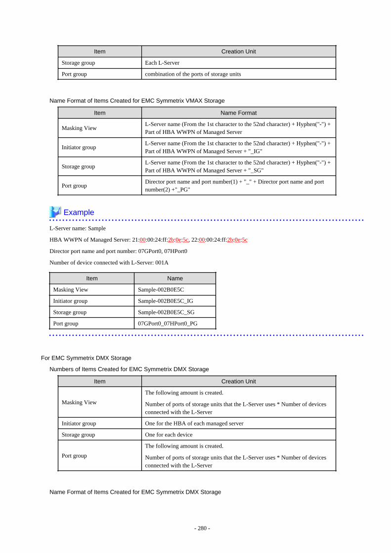
Item Creation Unit
Storage group Each L-Server
Port group combination of the ports of storage units
Name Format of Items Created for EMC Symmetrix VMAX Storage
Item Name Format
Masking ViewL-Server name (From the 1st character to the 52nd character) + Hyphen("-") +Part of HBA WWPN of Managed Server
Initiator groupL-Server name (From the 1st character to the 52nd character) + Hyphen("-") +Part of HBA WWPN of Managed Server + "_IG"
Storage groupL-Server name (From the 1st character to the 52nd character) + Hyphen("-") +Part of HBA WWPN of Managed Server + "_SG"
Port groupDirector port name and port number(1) + "_" + Director port name and portnumber(2) +"_PG"
Example
L-Server name: Sample
HBA WWPN of Managed Server: 21:00:00:24:ff:2b:0e:5c, 22:00:00:24:ff:2b:0e:5c
Director port name and port number: 07GPort0, 07HPort0
Number of device connected with L-Server: 001A
Item Name
Masking View Sample-002B0E5C
Initiator group Sample-002B0E5C_IG
Storage group Sample-002B0E5C_SG
Port group 07GPort0_07HPort0_PG
For EMC Symmetrix DMX Storage
Numbers of Items Created for EMC Symmetrix DMX Storage
Item Creation Unit
Masking View
The following amount is created.
Number of ports of storage units that the L-Server uses * Number of devicesconnected with the L-Server
Initiator group One for the HBA of each managed server
Storage group One for each device
Port group
The following amount is created.
Number of ports of storage units that the L-Server uses * Number of devicesconnected with the L-Server
Name Format of Items Created for EMC Symmetrix DMX Storage
- 280 -

Item Name Format
Masking ViewHBA WWPN of Managed Server + Director port name and port number +Number of device
Initiator group HBA WWPN of Managed Server
Storage group Number of device connected with L-Server
Port groupHBA WWPN of Managed Server + Director port name and port number +Number of device
Example
L-Server name: Sample
HBA WWPN of Managed Server: 21:00:00:24:ff:2b:0e:5c, 22:00:00:24:ff:2b:0e:5c
Director port name and port number: 07GPort0, 07HPort0
Number of device connected with L-Server: 001A
Item Name
Masking View21000024FF2B0E5C07G0001A22000024FF2B0E5C07H0001A
Initiator group21000024FF2B0E5C22000024FF2B0E5C
Storage group 001A
Port group21000024FF2B0E5C07G0001A22000024FF2B0E5C07H0001A
When Connecting EMC Symmetrix DMX Storage or EMC Symmetrix VMAX Storage to Fibre ChannelSwitches
In Resource Orchestrator, when connecting EMC Symmetrix DMX storage or EMC Symmetrix VMAX storage, Fibre Channel switchesare not configured.
It is necessary to configure one-to-one WWPN zoning for Fibre Channel switches in advance.
It is necessary to define zoning combining the fibre channel switch combining the HBA Port WWPN value based on the WWN providedby the I/O Virtualization Option and the DIRECTOR port WWPN value in the EMC Symmetrix DMX storage or EMC Symmetrix VMAXstorage used in Resource Orchestrator. For details on the configuration method, refer to the manual of the fibre channel switch.
Fibre Channel Switch Zoning Settings
Set zoning combining the WWPN value of HBA Port1 and the WWPN value of the first Director port defined in the storage_portset.rcxpropdefinition file, and combining the WWPN value of HBA Port2 and the WWPN value of the second Director port defined in portset.
Examples of command execution for an ETERNUS SN200 are as follows:
Example
Conditions
- WWN value provided by the I/O Virtualization Option
"20:00:00:17:42:51:00:0x"
- 281 -

- WWPN value of HBA Port1
"9:00:00 PM:17:42:51:00:0x"
- WWPN value of HBA Port2
"10:00:00 PM:17:42:51:00:0x"
- WWPN value of the DIRECTOR portset defined first
"50:0a:09:81:88:bc:43:dc"
- WWPN value of the DIRECTOR portset defined first
"50:0a:09:82:88:bc:43:dc"
zoneCreate "emc_a_0","50:0a:09:81:88:bc:43:dc;21:00:00:17:42:51:00:00" <RETURN>zoneCreate "emc_b_0","50:0a:09:82:88:bc:43:dc;22:00:00:17:42:51:00:00" <RETURN>...zoneCreate "emc_a_f","50:0a:09:81:88:bc:43:dc;21:01:00:17:42:50:00:0f" <RETURN>zoneCreate "emc_b_f","50:0a:09:82:88:bc:43:dc;22:01:00:17:42:50:00:0f" <RETURN>cfgCreate "ror_cfg","emc_a_0;emc_b_0; ... ;emc_a_f;emc_b_f" <RETURN>cfgEnable "ror_cfg" <RETURN>cfgSave <RETURN>
D.3.7 When Using Storage Server on which FalconStor NSS OperatesThis section explains how to configure Storage Server on which FalconStor NSS operates.
Configuration of Storage Server on which FalconStor NSS Operates
Resource Orchestrator controls FalconStor NSS through a SAN Client CLI installed on the management server.FalconStor NSS controls Storage Server and storage units connected with Storage Server.Therefore, the user ID and the password to use FalconStor NSS are necessary.
The type of user ID must be "IPstor Admin" or "IPStor User" (A user that manages storage devices to be used with this product).For details on how to add a user ID, refer to the FalconStor NSS manual.
Note
- The following settings are not configured in Resource Orchestrator. Therefore, configure these settings beforehand.
- Define Physical Devices (for Virtual Devices)
- Define Storage Pools (for Virtual Devices)
- Create Virtual Devices
For details on how to perform configuration, refer to the FalconStor NSS manual.
- The following are recognized as virtual storage in this product.
- Physical Device (for Virtual Device) not registered in Storage Pool
- Storage Pool (for Virtual Device)
- The following are recognized as disks in this product.
- A Virtual Device created from one PhysicalDevice (for Virtual Device)
- PhysicalDevice(for Service Enabled Device) is not recognized.
- StoragePool(for Service Enabled Device) is not recognized.
- PhysicalDevice (for Virtual Device) registered in StoragePool is not recognized.
- 282 -
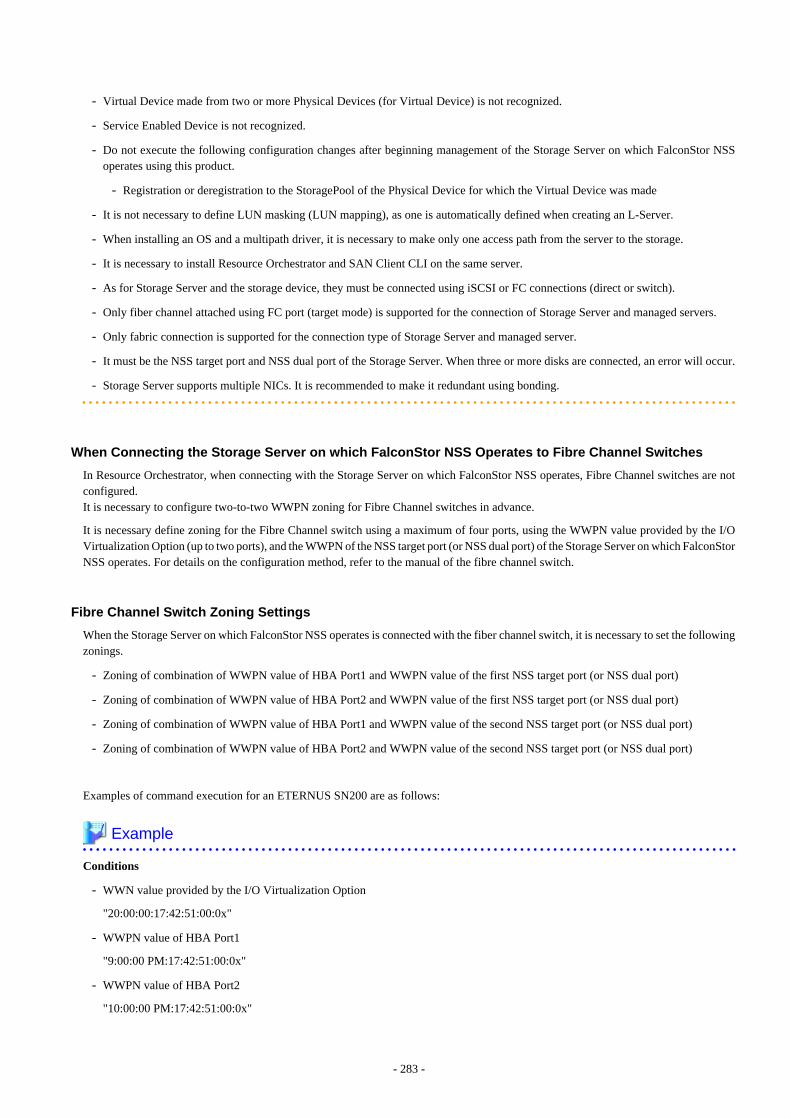
- Virtual Device made from two or more Physical Devices (for Virtual Device) is not recognized.
- Service Enabled Device is not recognized.
- Do not execute the following configuration changes after beginning management of the Storage Server on which FalconStor NSSoperates using this product.
- Registration or deregistration to the StoragePool of the Physical Device for which the Virtual Device was made
- It is not necessary to define LUN masking (LUN mapping), as one is automatically defined when creating an L-Server.
- When installing an OS and a multipath driver, it is necessary to make only one access path from the server to the storage.
- It is necessary to install Resource Orchestrator and SAN Client CLI on the same server.
- As for Storage Server and the storage device, they must be connected using iSCSI or FC connections (direct or switch).
- Only fiber channel attached using FC port (target mode) is supported for the connection of Storage Server and managed servers.
- Only fabric connection is supported for the connection type of Storage Server and managed server.
- It must be the NSS target port and NSS dual port of the Storage Server. When three or more disks are connected, an error will occur.
- Storage Server supports multiple NICs. It is recommended to make it redundant using bonding.
When Connecting the Storage Server on which FalconStor NSS Operates to Fibre Channel Switches
In Resource Orchestrator, when connecting with the Storage Server on which FalconStor NSS operates, Fibre Channel switches are notconfigured.It is necessary to configure two-to-two WWPN zoning for Fibre Channel switches in advance.
It is necessary define zoning for the Fibre Channel switch using a maximum of four ports, using the WWPN value provided by the I/OVirtualization Option (up to two ports), and the WWPN of the NSS target port (or NSS dual port) of the Storage Server on which FalconStorNSS operates. For details on the configuration method, refer to the manual of the fibre channel switch.
Fibre Channel Switch Zoning Settings
When the Storage Server on which FalconStor NSS operates is connected with the fiber channel switch, it is necessary to set the followingzonings.
- Zoning of combination of WWPN value of HBA Port1 and WWPN value of the first NSS target port (or NSS dual port)
- Zoning of combination of WWPN value of HBA Port2 and WWPN value of the first NSS target port (or NSS dual port)
- Zoning of combination of WWPN value of HBA Port1 and WWPN value of the second NSS target port (or NSS dual port)
- Zoning of combination of WWPN value of HBA Port2 and WWPN value of the second NSS target port (or NSS dual port)
Examples of command execution for an ETERNUS SN200 are as follows:
Example
Conditions
- WWN value provided by the I/O Virtualization Option
"20:00:00:17:42:51:00:0x"
- WWPN value of HBA Port1
"9:00:00 PM:17:42:51:00:0x"
- WWPN value of HBA Port2
"10:00:00 PM:17:42:51:00:0x"
- 283 -
- WWPN value of the first NSS target port (or NSS dual port)
"50:0a:09:81:88:bc:43:dc"
- WWPN value of the second NSS target port (or NSS dual port)
"50:0a:09:82:88:bc:43:dc"
Example Command
zoneCreate "nss_1_1_0","50:0a:09:81:88:bc:43:dc;21:00:00:17:42:51:00:00"zoneCreate "nss_2_1_0","50:0a:09:82:88:bc:43:dc;21:00:00:17:42:51:00:00"zoneCreate "nss_1_2_0","50:0a:09:81:88:bc:43:dc;22:00:00:17:42:51:00:00"zoneCreate "nss_2_2_0","50:0a:09:82:88:bc:43:dc;22:00:00:17:42:51:00:00"...zoneCreate "nss_1_1_f","50:0a:09:81:88:bc:43:dc;21:00:00:17:42:51:00:0f"zoneCreate "nss_2_1_f","50:0a:09:82:88:bc:43:dc;21:00:00:17:42:51:00:0f"zoneCreate "nss_1_2_f","50:0a:09:81:88:bc:43:dc;22:00:00:17:42:51:00:0f"zoneCreate "nss_2_2_f","50:0a:09:82:88:bc:43:dc;22:00:00:17:42:51:00:0f"cfgCreate "ror_cfg","nss_1_1_0;nss_2_1_0; nss_1_2_0;nss_2_2_0; ... ; nss_1_1_f;nss_2_1_f; nss_1_2_f;nss_2_2_f"cfgEnable "ror_cfg"cfgSave
D.4 Network PreparationsThis section explains the preparations for setting up a network.
The network environment and physical server required to run Resource Orchestrator must satisfy the following prerequisites:
- The configuration for the admin and public LANs has been designed
- The network environment for the admin LAN is configured
For details on the network environment for the admin LAN, refer to "9.1.1 Admin LAN Network Design".
Perform the following procedures if necessary.
- The configuration for the iSCSI LAN has been designed
For details on how to design and configure a network environment for iSCSI, refer to "9.1.3 Physical Network Design for the PublicLAN and iSCSI LAN".
Note
When using a physical L-Server, the default physical network adapter numbers available for the admin LAN are as given below.
- When not performing redundancy, "1" is available
- When performing redundancy, "1" and "2" are available
When using a NIC other than the default one, the configuration at the time of physical server registration and at L-Server creation mustbe the same. Thus when designing systems it is recommended that physical servers registered in the same server pool use the same NICindex.
On the physical L-Servers used by L-Platforms, only the default NIC can be used. The physical network adapter number for NetworkInterface Cards that can be used as an admin LAN on the L-Platform is as below:
- When not performing redundancy, "1" is available
- When performing redundancy, "1" and "2" are available
- 284 -

Information
The first NIC that is available for the admin LAN can be changed.
For details, refer to "5.4.2 Registering Blade Servers" in the "User's Guide for Infrastructure Administrators (Resource Management) CE".
When Using IBP
When using IBP, it is necessary to create IBP uplink set for the public LAN and the admin LAN in advance.
When using physical L-Servers, it is necessary to create an IBP uplink set for the public LAN and the admin LAN in advance, usingVIOM.
- Public LAN
Create a network resource with the same name as the created uplink set.
- Admin LAN
Describe the name of the admin LAN uplink set in the uplink set definition file for the admin LAN.
When there are no definition files, refer to "B.1.9 Definition File for Admin LAN Uplink Set" in the "Setup Guide CE".
When Using iSCSI
For details on the definition files for iSCSI network, refer to "B.1.10 Definition File for iSCSI Network" in the "Setup Guide CE".
- 285 -
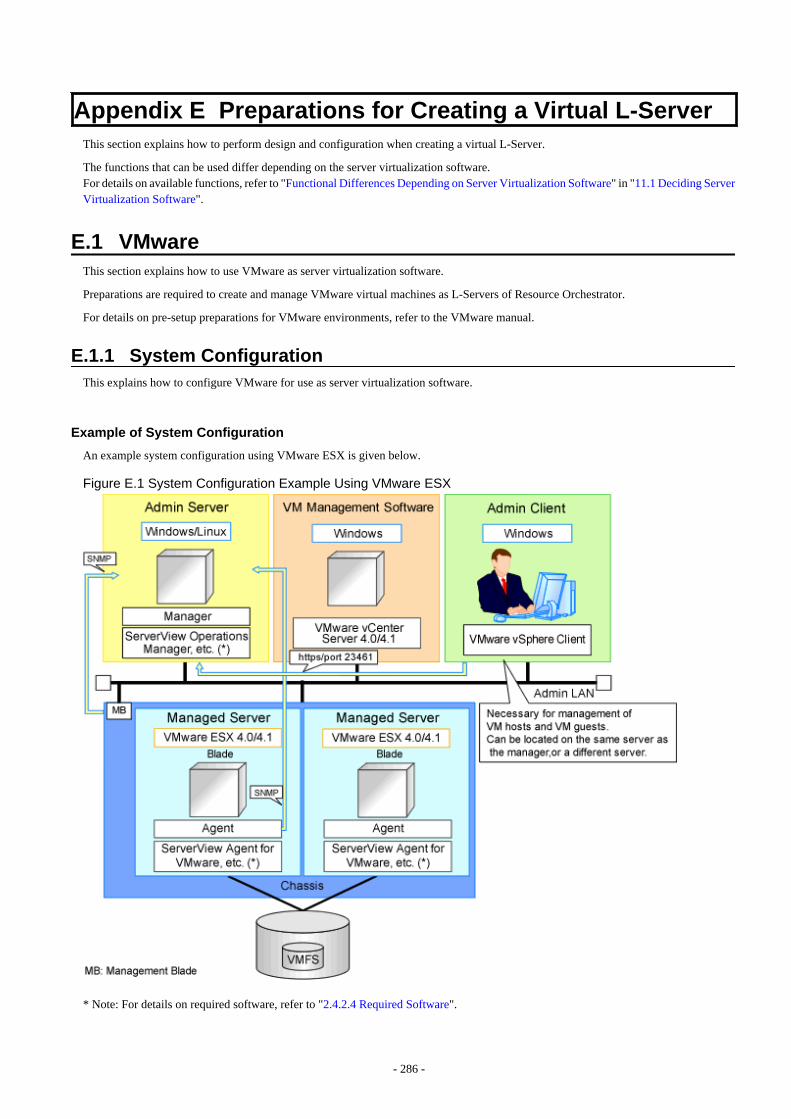
Appendix E Preparations for Creating a Virtual L-ServerThis section explains how to perform design and configuration when creating a virtual L-Server.
The functions that can be used differ depending on the server virtualization software.For details on available functions, refer to "Functional Differences Depending on Server Virtualization Software" in "11.1 Deciding ServerVirtualization Software".
E.1 VMwareThis section explains how to use VMware as server virtualization software.
Preparations are required to create and manage VMware virtual machines as L-Servers of Resource Orchestrator.
For details on pre-setup preparations for VMware environments, refer to the VMware manual.
E.1.1 System ConfigurationThis explains how to configure VMware for use as server virtualization software.
Example of System Configuration
An example system configuration using VMware ESX is given below.
Figure E.1 System Configuration Example Using VMware ESX
* Note: For details on required software, refer to "2.4.2.4 Required Software".
- 286 -
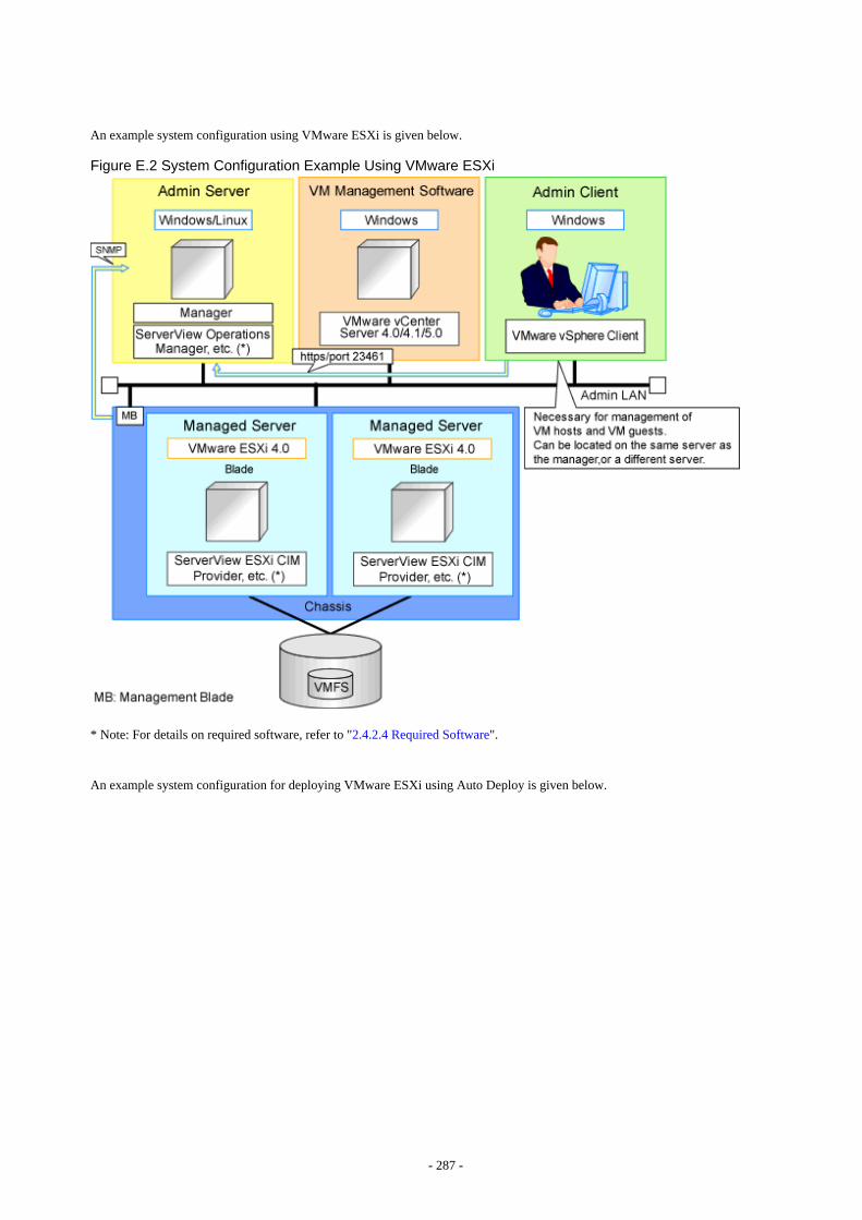
An example system configuration using VMware ESXi is given below.
Figure E.2 System Configuration Example Using VMware ESXi
* Note: For details on required software, refer to "2.4.2.4 Required Software".
An example system configuration for deploying VMware ESXi using Auto Deploy is given below.
- 287 -
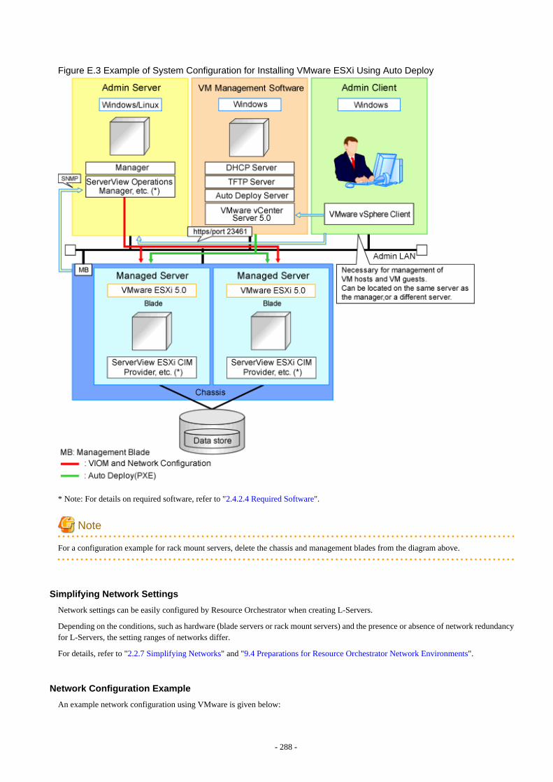
Figure E.3 Example of System Configuration for Installing VMware ESXi Using Auto Deploy
* Note: For details on required software, refer to "2.4.2.4 Required Software".
Note
For a configuration example for rack mount servers, delete the chassis and management blades from the diagram above.
Simplifying Network Settings
Network settings can be easily configured by Resource Orchestrator when creating L-Servers.
Depending on the conditions, such as hardware (blade servers or rack mount servers) and the presence or absence of network redundancyfor L-Servers, the setting ranges of networks differ.
For details, refer to "2.2.7 Simplifying Networks" and "9.4 Preparations for Resource Orchestrator Network Environments".
Network Configuration Example
An example network configuration using VMware is given below:
- 288 -
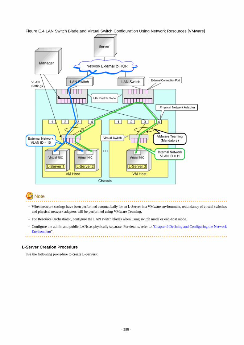
Figure E.4 LAN Switch Blade and Virtual Switch Configuration Using Network Resources [VMware]
Note
- When network settings have been performed automatically for an L-Server in a VMware environment, redundancy of virtual switchesand physical network adapters will be performed using VMware Teaming.
- For Resource Orchestrator, configure the LAN switch blades when using switch mode or end-host mode.
- Configure the admin and public LANs as physically separate. For details, refer to "Chapter 9 Defining and Configuring the NetworkEnvironment".
L-Server Creation Procedure
Use the following procedure to create L-Servers:
- 289 -

Figure E.5 Resource Orchestrator Setup Procedure
For details on pre-setup preparations, refer to "E.1 VMware".For details on how to install Resource Orchestrator, refer to "Chapter 2 Installation" in the "Setup Guide CE".For details on how to set up Resource Orchestrator, refer to "C.2 VMware" in the "Setup Guide CE".For details on how to create an L-Server, refer to "C.2.7 Creating an L-Server" in the "Setup Guide CE".
Point
- When Using VMware ESX
Install Resource Orchestrator agents and ServerView for VMware agents.
- When Using VMware ESXi
Install ServerView ESXi CIM Provider.
E.1.2 Preparations for ServersIn addition to the operations in "Chapter 8 Defining and Configuring the Server Environment", the following operations are necessary.
- Configure VIOM
When using I/O virtualization, configuration of VIOM is necessary.
- Install and configure VMware ESX
When installing an OS on a physical server, refer to the server virtualization software manual.
When installing a VM host on an L-Server, refer to "Appendix D Installing VM Hosts on Physical L-Servers" in the "Setup GuideCE".
- Install and configure VMware vCenter Server
Necessary for management of VM hosts and L-Servers.
It is necessary to install the Microsoft Sysprep tools for VMware vCenter Server to enable collection of L-Server cloning images. Fordetails on how to install the Microsoft Sysprep tools, refer to the installation section of "vSphere Basic System Administration" ofVMware.
Refer to the relevant version of document, referring to the following URL:
vSphere Basic System Administration
- 290 -
URL: http://www.vmware.com/support/pubs/vs_pubs.html
- Configure VMware clusters
When performing movement between servers (migration), register the source and destination VM hosts for migration in the samecluster.
When not performing redundancy of L-Servers, it is not necessary to enable VMware HA or VMware DRS.
- Design and configure VMware HA
When performing redundancy of L-Servers, VMware HA configuration must be done in advance.
When using VMware HA admission control, set "Percentage of cluster resources reserved" or "Specify failover hosts" for the admissioncontrol policy.
When multiple VM hosts are set for "Specify failover hosts", or a policy other than the above is set, the L-Server may fail to start.
- Design and configure VMware DPM, VMware DRS, VMware FT, and VMware Storage VMotion
When using VMware DPM, VMware DRS, VMware FT, or VMware Storage VMotion, configure them in advance using VMwarevCenter Server.
When setting configuration of VMware DRS or VMware DPM to "Manual", startup of L-Servers and VM guests may fail. For details,refer to "When using VMware DRS or VMware DPM".
- When using VMware DRS or VMware DPM
It is necessary to configure the following settings beforehand, when moving L-Servers between VM hosts on VMware DRS or whenturning on a VM host during an L-Server startup.
1. Configure VMware DRS and VMware DPM
Refer to VMware manuals and configure VMware DRS as "partly automatic" or "full automatic", or configure VMware DPMas "off" or "automatic".
When setting configuration of VMware DRS or VMware DPM to "Manual" and enabling the power control configuration ofVMware DRS or DPM, startup of the L-Server may fail. In this case, start the L-Server from VM management software.
2. Configure Power Control for VMware DRS and DPM
When configuring power control for VMware DRS or DPM, specify "true", referring to "Server Virtualization SoftwareDefinition File" in "C.2.1 Creating Definition Files" in the "Setup Guide CE".
- When using console connection of L-Server of VMware vSphere(VMware vSphere 5.1/5.5)
The console connection of L-Server of VMware vSphere communicates with the VM host where L-Server operates according to theproxy setting of browser.To use the console connection of L-Server of VMware vSphere through the proxy server, please connect a virtual switch of managementLAN of the VM host to the proxy server.
For details, refer to the VMware manual.
Information
When performing inter-cluster movement (migration), for VMware this means inter-resource pool movement (migration). Moving an L-Server (migration) is only possible in the same cluster (the same resource pool) because resource pools of VMware are not managed inResource Orchestrator. For details on resource pools of VMware, refer to the "vSphere Resource Management Guide" of VMware.
Refer to the relevant version of the document, referring to the following web site:
URL: http://www.vmware.com/support/pubs/vs_pubs.html
- 291 -
When Deploying VM Hosts Using Auto Deploy
1. Setup the Auto Deploy Server
Setup the Auto Deploy server.For details, refer to the manual of server virtualization software.
2. Configure the DHCP Server
Prepare a server other than admin server, and configure the DHCP server to be used by the Auto Deploy function.Perform configuration so the DHCP server assigns IP addresses only to VM hosts that have been configured using network bootservices that use DHCP protocols such as Auto Deploy.For details, refer to the manual of the server used as the DHCP server.
3. Configure the TFT Server
Prepare a server other than admin server, and configure the TFTP server to be used by the Auto Deploy function.For details, refer to the manual of the server used as the TFTP server.
4. Setup a VM Host
Setup a VM host for a physical L-Server.Refer to "Appendix D Installing VM Hosts on Physical L-Servers" in the "Setup Guide CE", and set up VM hosts.
Point
- When creating an L-Server, prepare a disk for the dump area.
At least one disk should be prepared specifying a disk that is not shared with other L-Servers.On that disk, create a dump area for VMware ESXi.
- For the first L-Server that uses Auto Deploy, prepare the necessary number of disks with the disk capacity necessary for storingVM guests to share with other L-Servers.
When there are two or more L-Servers, prepare the disk for storing VM guests connected to the first L-Server.
On that disk, create an area for VMFS to use as a datastore.
- When configuring a VM host using Auto Deploy, use VIOM for I/O virtualization.
Note
As HBA address rename requires PXE boot, use in combination with Auto Deploy using the same PXE boot is not possible.
E.1.3 Storage PreparationsThis section explains the preparations for setting up storage.
Supported Storage Configurations
The supported storage configurations are as follow:
- Storage supported by VMware
For details on the storage supported by VMware, refer to the VMware manual.
- Storage configured for datastores of VMware ESX/ESXi (VMFS Version 3 or later, or NFS mount), including L-Server system disksand data disks
Preparations for Storage Environments
Check the following:
- 292 -
- Volumes to allocate to VMware ESX/VMware ESXi have been already created
- Zoning and affinity have been set
- VMware ESX/VMware ESXi has been configured to recognize a VMFS datastore
Information
By registering the agent of the VM management software and the VM host with Resource Orchestrator, VMFS (datastores) are detectedas virtual storage resources in Resource Orchestrator.
The datastore name is used for the virtual storage resource name. However, when characters other than the following are included in adatastore name, they are replaced with hyphens ("-").When this product manages two or more vCenters, there may be multiple datastores with the same name. In that case, the form of virtualstorage resource names is the datastore name + "_" + serial number (Example: "_1").
- Numerals (0 to 9)
- Alphabetical characters: upper case (A to Z), lower case (a to z)
- Hyphens ("-") and underscores ("_")
E.1.4 Network PreparationsCheck the following:
- The configuration for the admin and public LANs has been designed
- The network environment for the admin LAN is configured
- The virtual switch to connect to the admin LAN has been designed and configured
When Using IBP
When using virtual L-Servers, connect the IBP uplink sets used for the public LAN and admin LAN to the VM host regardless of VIOM,after creating each IBP uplink set.
It is not necessary to use the same name for the uplink set and the name of the network resource.
Point
- For VMware virtual switches, configuration is not necessary as they are automatically configured by Resource Orchestrator.
- When performing movement between servers (migration), configure the VMkernel port group for VMotion on each VM host.
- For details on how to configure the VMkernel port group, refer to the information in "vSphere Basic System Administration" ofVMware.
Refer to the relevant version of the document, referring to the following web site:
vSphere Basic System Administration
URL: http://www.vmware.com/support/pubs/vs_pubs.html
When Using Distributed Virtual Switch (VMware vDS)
In Resource Orchestrator, the NICs of VM guests and port groups can be connected to the port groups of a distributed virtual switch(VMware vDS). The port groups of the distributed virtual switch should be configured beforehand manually.
When using VMware vDS, the following preparation is necessary:
- 293 -
1. Create Port Groups of the Distributed Virtual Switch
Refer to the VMware manual, and create them manually.
2. Define the Correspondence of the Port Groups of the Distributed Virtual Switch and VLAN IDs
Create the distributed virtual network definition file shown below, and associate the port groups and the VLAN IDs:
Storage location of distributed virtual network definition files
[Windows Manager]Installation_folder\SVROR\Manager\etc\customize_data
[Linux Manager]/etc/opt/FJSVrcvmr/customize_data
Distributed virtual network definition file name
vnetwork_vmware.rcxprop
File format for distributed virtual network definitions
Describe the distributed virtual network definition file in individual lines in the following format:
"Port_group_name_of_Distributed_Virtual_Switch"=VLAN ID[,VLAN ID...]
For the VLAN ID, an integer between 1 and 4094 can be specified. When specifying a sequence of numbers, use a hyphen ("-")such as in "1-4094".
Example
"Network A"=10"Network B"=21,22,23"Network C"=100-200,300-400,500
- Blank spaces before and after equal signs ("=") and commas (",") are ignored.
- Describe the port group name of the distributed virtual switch correctly, as entry is case-sensitive.
- Use the UTF-8 character code.
- When there are multiple lines with the same distributed virtual switch port group name, all specified lines are valid.
- When the same VLAN ID is used in lines where the port group names of different distributed virtual switches are described,the VLAN ID in the first line is valid.
3. Place the Distributed Virtual Switch Usage Configuration File
Place the distributed virtual switch use configuration file. Create the following folder and place an empty file in it.
Storage location of distributed virtual switch usage configuration files
[Windows Manager]Installation_folder\SVROR\Manager\etc\vm
[Linux Manager]/etc/opt/FJSVrcvmr/vm
Distributed virtual switch usage configuration name
vds_vc
- 294 -
When Using the Definition for Port Groups Excluded from the Selections for Automatic NetworkConfiguration
If the names of the port groups to be excluded from automatic network configuration have been specified in the VMware excluded portgroup definition file, creation of L-Servers is possible, even if the VLAN set for the service console or VMkernel network and the one setfor the port group on the virtual switch is the same.
When using a VMware excluded port group definition, the following preparation is necessary:
1. On the managed server, create a port group of the service console (or VMkernel) and the virtual switch that use the same VLANID.
Refer to the VMware manual, and create them manually.
2. Create a VMware excluded port group definition file, and define the name of the service console created in step 1 as the port groupname to be excluded.
Storage location of the VMware excluded port group definition file
[Windows Manager]Installation_folder\SVROR\Manager\etc\customize_data
[Linux Manager]/etc/opt/FJSVrcvmr/customize_data
File name of the VMware excluded port group definition file
vnetwork_excluded_vmware.rcxprop
File format for the VMware excluded port group definition file
Describe the VMware excluded port group definition file in individual lines in the following format:
Port_group_name_to_be_excluded
Example
Service ConsoleVMkernelService Console2
- Lines starting with "#" are regarded as comments, and ignored.
- Blank lines are ignored.
- Describe Port_group_name_to_be_excluded correctly, as the entry is case-sensitive.
- Use the UTF-8 character code.
- For the Port_group_name_to_be_excluded, from the front of the line to the line break code in each line is regarded as asingle name.
- When there are multiple lines with the same Port_group_name_to_be_excluded, all specified lines are valid.
Note
When using the definition of the port groups excluded from the selections for automatic network configuration, take note of thefollowing points:
- The VLAN of the service console and VMkernel network is the admin LAN. As this configuration allows a public LAN usingthe same VLAN, security risks increase.
For these reasons, that this configuration is for users using the same VLAN in the system configuration. The infrastructureadministrator should determine if these directions can be used or not, taking possible security risks into account.
- 295 -
When Performing Alive Monitoring (Heartbeat Monitoring) for L-Server
For Resource Orchestrator alive monitoring functions, "VM Monitoring" functions for VMware HA are used. Therefore, configure thefollowing settings:
1. Configure VMware Clusters
Configure VMware clusters in a VM host operating an L-Server.
2. Configure VMware HA
Enable VMware HA in VMware clusters configured in step 1.
When using Console Connections from Public LAN
Use the following procedure when using console connections from the public LAN. For details on the configuration method, refer to theVM management software manual.
1. Create a virtual switch to connect with the public LAN on VM management software.
2. Create a Service Console or port group for VMKernel on the created virtual switch on VM management software.
- When Using VMware ESX
Create a port group for Service Console.
- When Using VMware ESXi
Create a port group for VMKernel.
When creating port groups for Service Console or VMkernel, configure IP addresses and VLAN IDs for the VM host to match tothe settings of the public LAN which is the destination for connection. When using multiple network resources as public LANs,create port groups for Service Console or VMKernel corresponding to each resource, and configure the IP addresses and VLANIDs appropriately.
3. Configure port groups excluded from the selection for automatic network configuration in Resource Orchestrator.
The VLAN ID for network resources corresponding to the public LAN and the VLAN ID for Service Console or VMKernel maybe the same. Therefore, define the port group for the Service Console or VMKernel created in step 2 for the port group to be excludedfrom selection for automatic network configuration.
For details, refer to "When Using the Definition for Port Groups Excluded from the Selections for Automatic NetworkConfiguration".
4. Configure the IP addresses to exclude from allocation in Resource Orchestrator.
Set the IP address of the VM host configured for public LANs in step 2, in the network corresponding to the public LAN, to beexcluded from allocation.
For details, refer to the following:
- "7.5 Modifying Network Resource Specifications" in the "User's Guide for Infrastructure Administrators (ResourceManagement) CE".
- "14.3.1 Creating New Network Resources" in the "User's Guide for Infrastructure Administrators (Resource Management) CE".
Note
When using console connection of L-Server in the following environments from Public LAN through the proxy server, please connect thevirtual switch to the proxy server in step 1.
- VMware vSphere 5.1
- VMware vSphere 5.5
- 296 -
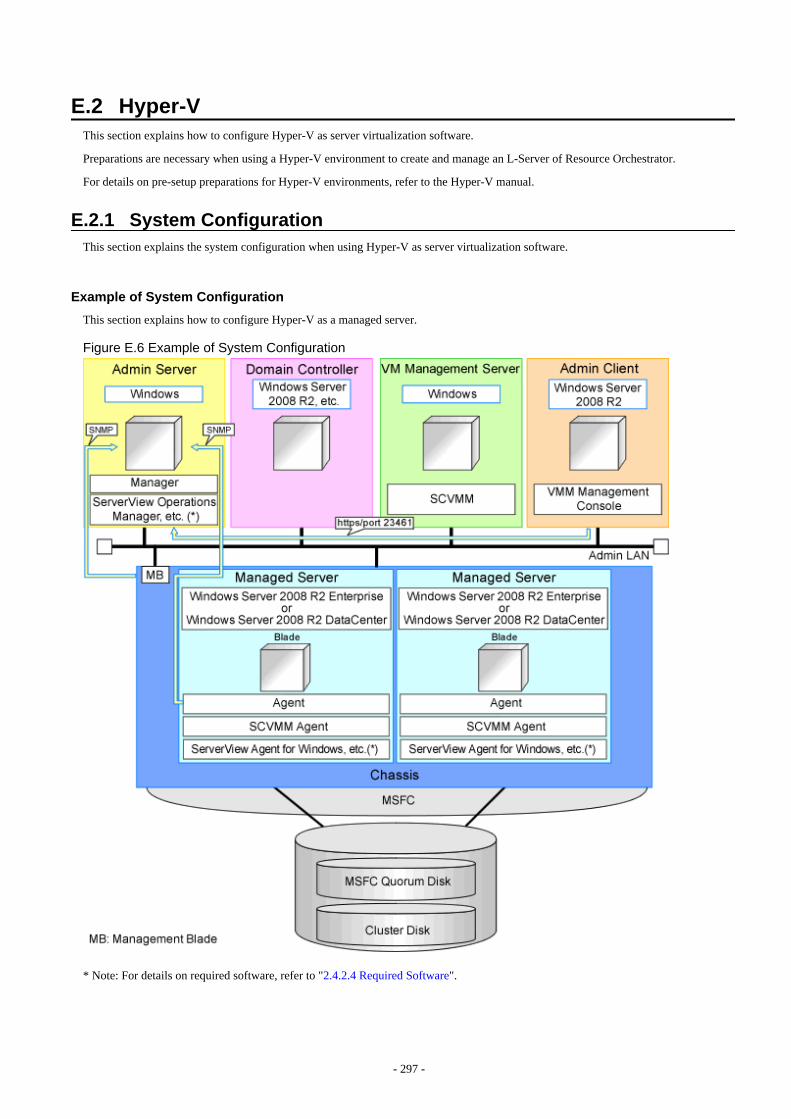
E.2 Hyper-VThis section explains how to configure Hyper-V as server virtualization software.
Preparations are necessary when using a Hyper-V environment to create and manage an L-Server of Resource Orchestrator.
For details on pre-setup preparations for Hyper-V environments, refer to the Hyper-V manual.
E.2.1 System ConfigurationThis section explains the system configuration when using Hyper-V as server virtualization software.
Example of System Configuration
This section explains how to configure Hyper-V as a managed server.
Figure E.6 Example of System Configuration
* Note: For details on required software, refer to "2.4.2.4 Required Software".
- 297 -
Note
- For a configuration example for rack mount servers, delete the chassis and management blades from the diagram above.
- For the manager, agents, SCVMM, SCVMM agents, and Windows guest OSs, apply the latest updated program using MicrosoftUpdate. Necessary for installing the latest integrated services provided by each OS on VM guests.
SCVMM
Necessary for management of VM hosts and VM guests.
Can be placed on the same admin server as the manager or on another server.
Can be placed on the same server as the domain controller or on another server.
SCVMM must be in the domain of the domain controller in this configuration.
Domain Controller
Can be placed on the same admin server as the manager or on another server.
Can be placed on the same server as SCVMM or on another server.
Managed Server
Create a cluster using MSFC.
Managed servers must be in the domain of the domain controller in this configuration.
Admin Client
Must be in the same domain as SCVMM and the VM host. The SCVMM administrator console must be installed.
Advisory Notes for System Configuration
- SCVMM and the VM host must be in the same domain.
- SCVMM and a VM host cannot be placed on the same server, when simplifying of network settings is used.
- The VM host must be connected to the Resource Orchestrator admin LAN.
- For the Resource Orchestrator manager, it is recommended that the configuration enables access to SCVMM through the ResourceOrchestrator admin LAN.
- When opening the SCVMM management window from an ROR console executed on a Resource Orchestrator admin client, the adminclient must be in the same domain as SCVMM, and logged in to the domain account.
- When connecting with the L-Server console from the ROR console executed on the admin client of Resource Orchestrator, the adminclient must be in the same domain as SCVMM.
Simplifying Network Settings
Network settings can be easily configured by Resource Orchestrator when creating L-Servers.
Depending on the conditions, such as hardware (such as blade servers or rack mount servers) used and whether or not network redundancyis performed for L-Servers, the setting ranges of networks differ.
For details, refer to "2.2.7 Simplifying Networks" and "9.4 Preparations for Resource Orchestrator Network Environments".
- 298 -
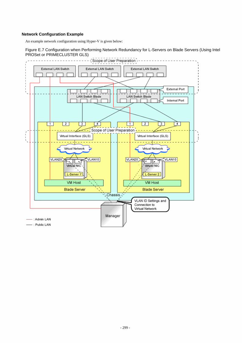
Network Configuration Example
An example network configuration using Hyper-V is given below:
Figure E.7 Configuration when Performing Network Redundancy for L-Servers on Blade Servers (Using IntelPROSet or PRIMECLUSTER GLS)
- 299 -
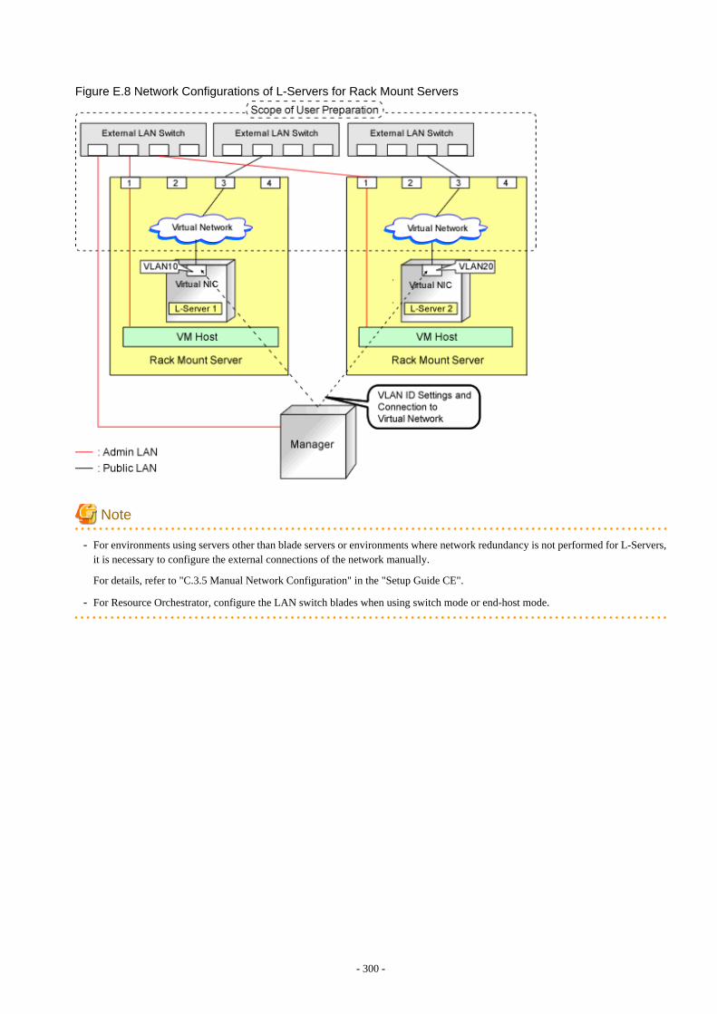
Figure E.8 Network Configurations of L-Servers for Rack Mount Servers
Note
- For environments using servers other than blade servers or environments where network redundancy is not performed for L-Servers,it is necessary to configure the external connections of the network manually.
For details, refer to "C.3.5 Manual Network Configuration" in the "Setup Guide CE".
- For Resource Orchestrator, configure the LAN switch blades when using switch mode or end-host mode.
- 300 -
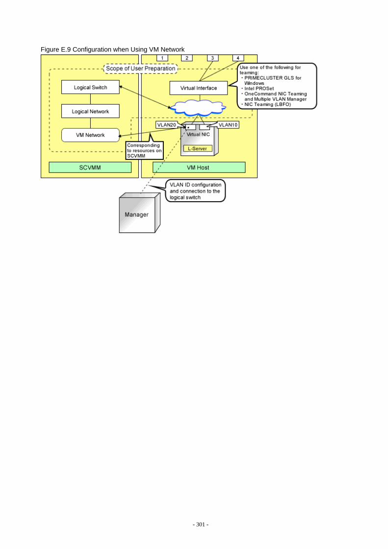
Figure E.9 Configuration when Using VM Network
- 301 -
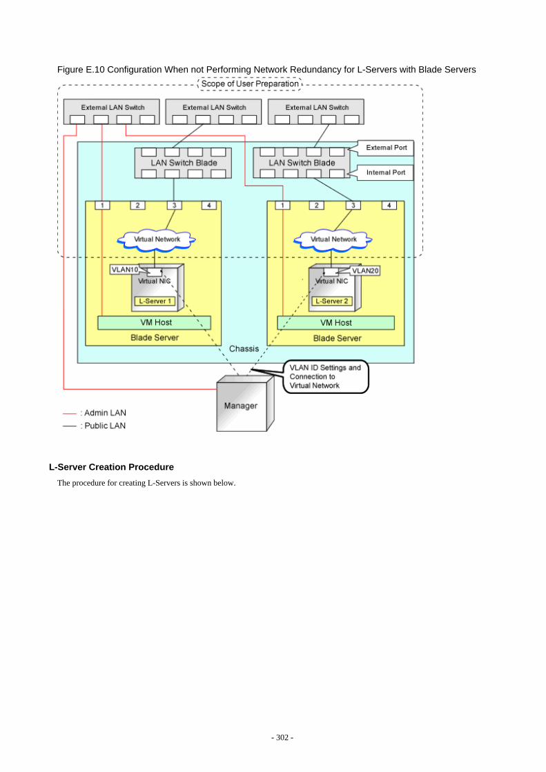
Figure E.10 Configuration When not Performing Network Redundancy for L-Servers with Blade Servers
L-Server Creation Procedure
The procedure for creating L-Servers is shown below.
- 302 -
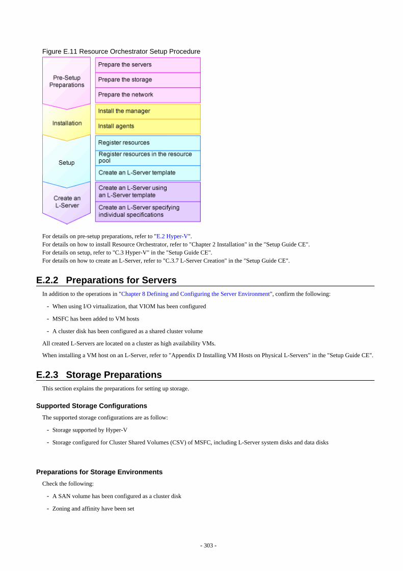
Figure E.11 Resource Orchestrator Setup Procedure
For details on pre-setup preparations, refer to "E.2 Hyper-V".For details on how to install Resource Orchestrator, refer to "Chapter 2 Installation" in the "Setup Guide CE".For details on setup, refer to "C.3 Hyper-V" in the "Setup Guide CE".For details on how to create an L-Server, refer to "C.3.7 L-Server Creation" in the "Setup Guide CE".
E.2.2 Preparations for ServersIn addition to the operations in "Chapter 8 Defining and Configuring the Server Environment", confirm the following:
- When using I/O virtualization, that VIOM has been configured
- MSFC has been added to VM hosts
- A cluster disk has been configured as a shared cluster volume
All created L-Servers are located on a cluster as high availability VMs.
When installing a VM host on an L-Server, refer to "Appendix D Installing VM Hosts on Physical L-Servers" in the "Setup Guide CE".
E.2.3 Storage PreparationsThis section explains the preparations for setting up storage.
Supported Storage Configurations
The supported storage configurations are as follow:
- Storage supported by Hyper-V
- Storage configured for Cluster Shared Volumes (CSV) of MSFC, including L-Server system disks and data disks
Preparations for Storage Environments
Check the following:
- A SAN volume has been configured as a cluster disk
- Zoning and affinity have been set
- 303 -
- The configuration enables use of SAN environments on VM hosts
Information
Once the infrastructure administrator registers VM management software and VM host agents, CSV is detected as a virtual storage resourceof Resource Orchestrator.
The CSV name is used for the virtual storage resource name. However, when characters other than the following are included in the CSVname, they are replaced with hyphens ("-").
When this product manages two or more SCVMMs, there may be multiple CSVs with the same name. In that case, the form of virtualstorage resource names is the CSV name + "_" + serial number (Example: "_1").
- Numerals (0 to 9)
- Alphabetical characters: upper case (A to Z), lower case (a to z)
- Hyphens ("-") and underscores ("_")
E.2.4 Network PreparationsIn addition to the operations in "Chapter 9 Defining and Configuring the Network Environment", confirm the following:
- The configuration for the admin and public LANs has been designed
- The network environment for the admin LAN is configured
- The virtual switch to connect to the admin LAN has been designed and configured
- When performing network redundancy for L-Servers, using Intel PROSet or PRIMECLUSTER GLS with blade servers
- The external LAN switch to connect to the LAN switch blade has been designed and configured
- The LAN switch blade has been designed
- When not performing network redundancy for L-Servers with blade servers
- The external LAN switch to connect to the LAN switch blade has been designed and configured
- The LAN switch blade has been designed and configured
- When using servers other than blade servers
- The external LAN switch to connect to servers other than blade servers has been designed and configured
See
- For details on the server NIC definitions, refer to "15.12 Server NIC Definition" in the "Reference Guide (Command/XML) CE".
- For details on the rcxadm nicdefctl command, refer to "5.15 rcxadm nicdefctl" in the "Reference Guide (Command/XML) CE".
When Using IBP
When using virtual L-Servers, connect the IBP uplink sets used for the public LAN and admin LAN to the VM host regardless of VIOM,after creating each IBP uplink set.
It is not necessary to use the same name for the uplink set and the name of the network resource.
- 304 -
E.2.5 Pre-setup Preparations in Hyper-V EnvironmentsUse the following procedure for pre-setup preparations for Hyper-V environments.For details, refer to the MSFC help.
1. Installation of an Operating System and Configuration of a Domain Controller on the Domain Controller Server
2. Storage Preparations
Creation of the volume (LUN) for allocation to the MSFC of the managed server (quorum disk and cluster disk)
3. Configuration of Managed Servers
a. BIOS configuration (hardware virtualization and Data Execution Prevention (DEP))
b. Install an OS
When installing an OS on a physical server, refer to the server virtualization software manual.
When installing a VM host on an L-Server, refer to "Appendix D Installing VM Hosts on Physical L-Servers" in the "SetupGuide CE".
c. Join a domain
d. Add SNMP services
e. Configure SNMP services and SNMP traps
f. Add Hyper-V roles
g. Add a failover cluster function
4. Cluster Configuration of Managed Servers (MSFC)
a. Create an access point for cluster management on the admin LAN side.
b. In a quorum configuration, select one of the following:
- When the number of nodes is even
Select [Node and Disk Majority], and specify a quorum disk.
- When the number of nodes is uneven
Select [Node Majority].
c. Enable the shared volume of the cluster.
d. Add a cluster disk to a shared cluster volume.
5. Configuration After Creation of Clusters for Managed Servers
a. Enable remote WMI settings.
1. In each VM host, access the Control Panel and open the [Administrative Tools]-[Computer Management].
The [Computer Management] window is displayed.
2. Open [Services and Applications], right-click on [WMI Control] and select [Properties].
The [WMI Control Properties] dialog is displayed.
3. Open the [Security] tab, select [Root]-[virtualization] and click <Security>.
The [Security for ROOT\virtualization] window is displayed.
4. Select the login user for the VM host, and check [Allow] from [Remote Enable].
5. When using Windows Server 2012 R2, the following procedure is also needed.
a. Open the [Security] tab, select [Root]-[virtualization]-[v2] and click <Security>.
The [Security for ROOT\virtualization\v2] window is displayed.
b. Select the login user for the VM host, and check "Allow" from "Remote Enable".
- 305 -
c. Click <OK>.
6. Open the [Security] tab, select [Root]-[MSCluster] and click <Security>.
The [Security for ROOT\MSCluster] window is displayed.
7. Check if all checkboxes are selected, excluding "Special Permissions" for the local Administrators group for the VMhost. When these checkboxes are not selected, check the checkboxes.
In the default settings, these checkboxes, other than, "Special Permissions" are all selected.
8. Click <OK>.
The remote WMI settings are enabled.
b. Configure the Windows firewall to enable remote WMI management.
1. On each VM host, run the "GPedit.msc" command.
The [Local Group Policy Editor] dialog is displayed.
2. Select the following folder:
[Computer Configuration]-[Administrative Templates]-[Network]-[Network Connections]-[Windows Firewall]
3. If the VM host is a member of a domain, double-click [Domain Profile]; otherwise double-click [Standard Profile].
Either one of the [Domain Profile] or [Standard Profile] screen is displayed.
4. Right-click [Windows Firewall: Allow remote administration exception properties], and select [Properties].
The [Windows Firewall: Allow remote administration exception properties] window is displayed.
5. Select "Enabled".
6. Click <OK>.
c. Configure DCOM.
1. On each VM host, run the "Dcomcnfg.exe" command.
The [Component Services] window is displayed.
2. Right-click [Component Services]-[Computers]-[My Computer], and select [Properties].
The [My Computer Properties] window is displayed.
3. Select the [COM Security] tab.
4. Click <Edit Limits> from [Launch and Activation Permissions].
The [Launch and Activation Permission] window is displayed.
5. Select the VM host's user name under [Groups or user names:], and select the [Allow] checkbox for [Remote Launch]and [Remote Activation].
6. Click <OK>.
7. Click <Edit Limits> under [Access Permissions].
The [Access Permission] window is displayed.
8. Select [ANONYMOUS LOGON] under [Group or user names], and check the [Allow] checkbox for [Remote Access].
9. Click <OK>.
6. Configuration and Installation of SCVMM
Use the following procedure to install and configure SCVMM:
a. Install an OS
b. Join a domain
- 306 -
c. Install SCVMM
Install a VMM server and a VMM management console.
d. Register a VM host
Register by the cluster. An SCVMM agent is automatically installed on newly registered VM hosts.
e. Configure Windows remote management environment
Configure remote administration on VM management software registered with Resource Orchestrator.
1. Log in to the server on which VM management software operates, using administrative privileges.
2. Execute the following command from the command prompt.
>winrm quickconfig <RETURN>
3. Enter "y", when requested.
f. SCVMM Server Web Services for Management Settings
7. Configure the Resource Orchestrator Admin Server
Configure remote management authentication settings on the machine the Resource Orchestrator admin server will be set up.
a. Log on to the admin server as the administrator.
b. Execute the following command from the command prompt to record the configuration details for TrustedHosts.
>winrm get winrm/config/client <RETURN>
Record the displayed details in TrustedHosts.
Example
When multiple SCVMMs are registered
192.168.1.100, 192.168.1.101
When a single asterisk ("*") is displayed, the following procedure is unnecessary as all hosts will be trusted in theconfiguration.
c. Execute the following command.
Enter the result obtained from b. for Recorded_content_in_b.
>winrm set winrm/config/client @{TrustedHosts="Recorded_content_in_b. , Additionally_registered_SCVMM_address"} <RETURN>
Example
The command specification when multiple SCVMMs are registered
>winrm set winrm/config/client @{TrustedHosts="192.168.1.100, 192.168.1.101, Additionally_registered_SCVMM_address"} <RETURN>
d. Execute the following command to check the details for TrustedHosts.
>winrm get winrm/config/client <RETURN>
If the address of the SCVMM additionally registered has been added to the details recorded in b., there are no problems.
- 307 -
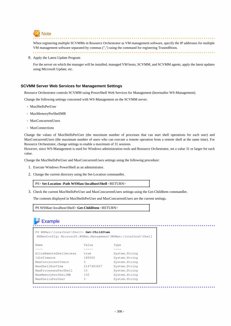
Note
When registering multiple SCVMMs in Resource Orchestrator as VM management software, specify the IP addresses for multipleVM management software separated by commas (",") using the command for registering TrustedHosts.
8. Apply the Latest Update Program
For the server on which the manager will be installed, managed VM hosts, SCVMM, and SCVMM agents, apply the latest updatesusing Microsoft Update, etc.
SCVMM Server Web Services for Management Settings
Resource Orchestrator controls SCVMM using PowerShell Web Services for Management (hereinafter WS-Management).
Change the following settings concerned with WS-Management on the SCVMM server.
- MaxShellsPerUser
- MaxMemoryPerShellMB
- MaxConcurrentUsers
- MaxConnections
Change the values of MaxShellsPerUser (the maximum number of processes that can start shell operations for each user) andMaxConcurrentUsers (the maximum number of users who can execute a remote operation from a remote shell at the same time). ForResource Orchestrator, change settings to enable a maximum of 31 sessions.However, since WS-Management is used for Windows administration tools and Resource Orchestrator, set a value 31 or larger for eachvalue.
Change the MaxShellsPerUser and MaxConcurrentUsers settings using the following procedure:
1. Execute Windows PowerShell as an administrator.
2. Change the current directory using the Set-Location commandlet.
PS> Set-Location -Path WSMan:\localhost\Shell <RETURN>
3. Check the current MaxShellsPerUser and MaxConcurrentUsers settings using the Get-ChildItem commandlet.
The contents displayed in MaxShellsPerUser and MaxConcurrentUsers are the current settings.
PS WSMan:\localhost\Shell> Get-ChildItem <RETURN>
Example PS WSMan:\localhost\Shell> Get-ChildItem WSManConfig: Microsoft.WSMan.Management\WSMan::localhost\Shell
Name Value Type---- ----- ----AllowRemoteShellAccess true System.StringIdleTimeout 180000 System.StringMaxConcurrentUsers 5 System.StringMaxShellRunTime 2147483647 System.StringMaxProcessesPerShell 15 System.StringMaxMemoryPerShellMB 150 System.StringMaxShellsPerUser 5 System.String
- 308 -

4. Configure MaxShellsPerUser and MaxConcurrentUsers using the Set-Item commandlet.
Example
When setting MaxShellsPerUser and MaxConcurrentUsers as "36"
PS WSMan:\localhost\Shell> Set-Item .\MaxShellsPerUser 36 <RETURN>PS WSMan:\localhost\Shell> Set-Item .\MaxConcurrentUsers 36 <RETURN>
Next, change the MaxMemoryPerShellMB setting.For Resource Orchestrator, change the setting to over 1024 MB.
Change the MaxMemoryPerShellMB setting using the following procedure:
1. Check the current MaxMemoryPerShellMB setting using the Get-ChildItem commandlet.
The content displayed in MaxMemoryPerShellMB is the current setting.
PS WSMan:\localhost\Shell> Get-ChildItem <RETURN>
2. Configure MaxShellsPerUser using the Set-Item commandlet.
Example
When setting MaxMemoryPerShellMB as "1024"
PS WSMan:\localhost\Shell> Set-Item .\MaxMemoryPerShellMB 1024 <RETURN>
Finally, change the MaxConnections setting. In Resource Orchestrator, the maximum number of sessions is 31, so change the setting.Since WS-Management is used for Windows administration tools and Resource Orchestrator, set a value of 32 or larger.
Change the MaxConnections setting using the following procedure:
1. Change the current directory using the Set-Location commandlet.
PS> Set-Location -Path WSMan:\localhost\Service <RETURN>
2. Check the current MaxConnections setting using the Get-ChildItem commandlet.
The content displayed in MaxConnections is the current setting.
PS WSMan:\localhost\Service> Get-ChildItem <RETURN>
3. Configure MaxConnections using the Set-Item commandlet.
Example
When setting MaxConnections as "46"
PS WSMan:\localhost\Service> Set-Item .\MaxConnections 46 <RETURN>
E.3 RHEL5-XenThis section explains how to configure RHEL5-Xen as server virtualization software.
- 309 -
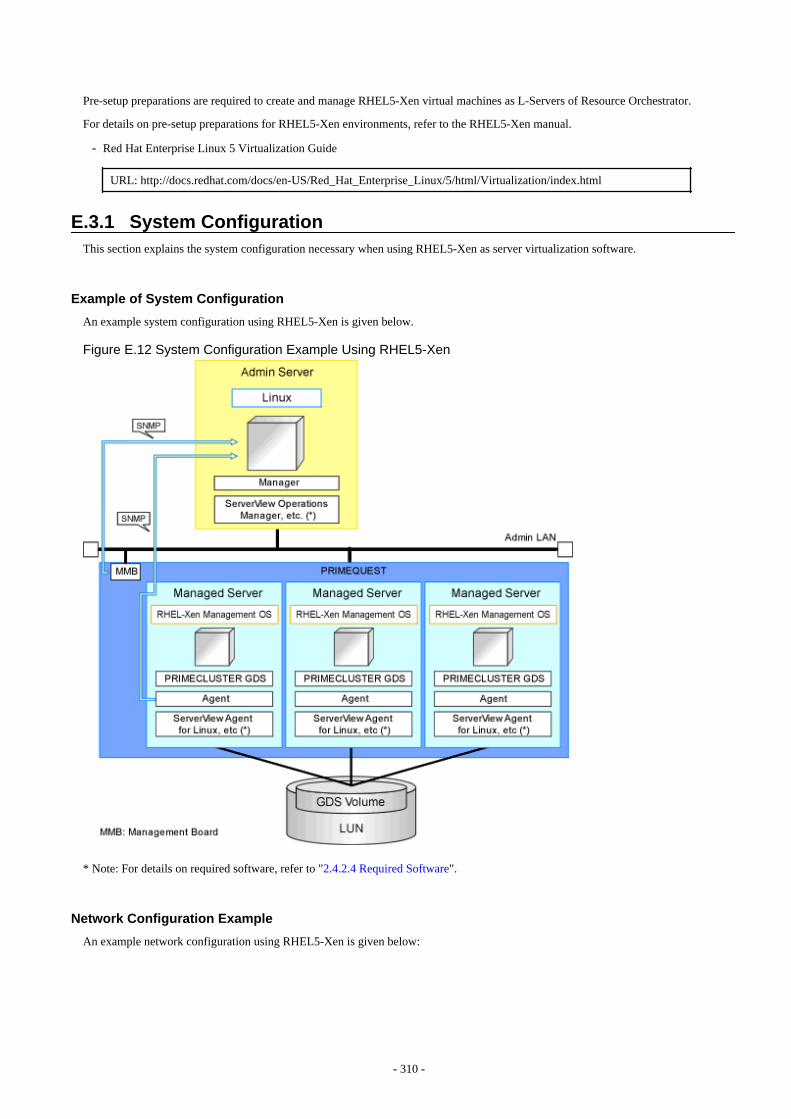
Pre-setup preparations are required to create and manage RHEL5-Xen virtual machines as L-Servers of Resource Orchestrator.
For details on pre-setup preparations for RHEL5-Xen environments, refer to the RHEL5-Xen manual.
- Red Hat Enterprise Linux 5 Virtualization Guide
URL: http://docs.redhat.com/docs/en-US/Red_Hat_Enterprise_Linux/5/html/Virtualization/index.html
E.3.1 System ConfigurationThis section explains the system configuration necessary when using RHEL5-Xen as server virtualization software.
Example of System Configuration
An example system configuration using RHEL5-Xen is given below.
Figure E.12 System Configuration Example Using RHEL5-Xen
* Note: For details on required software, refer to "2.4.2.4 Required Software".
Network Configuration Example
An example network configuration using RHEL5-Xen is given below:
- 310 -

Figure E.13 Virtual Bridge Settings Using Network Resources
L-Server Creation Procedure
Use the following procedure to create L-Servers:
- 311 -
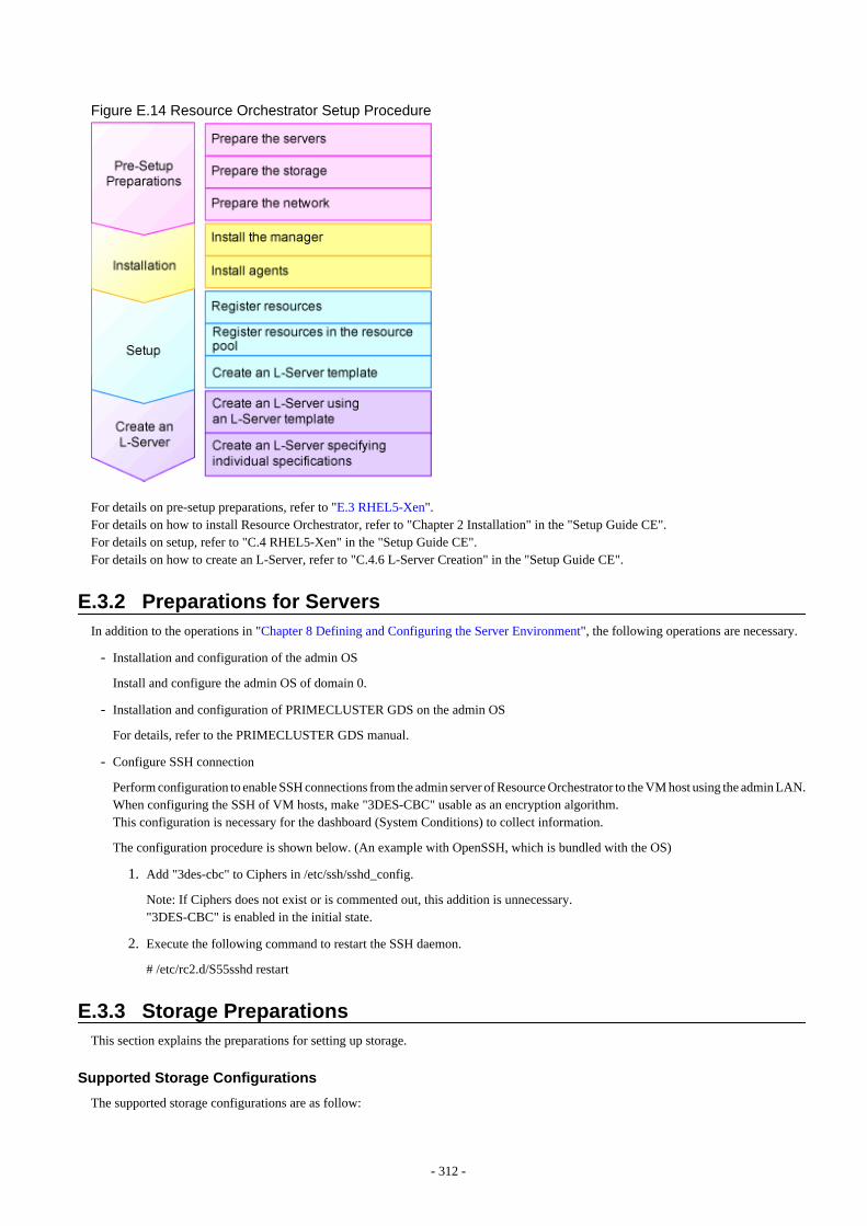
Figure E.14 Resource Orchestrator Setup Procedure
For details on pre-setup preparations, refer to "E.3 RHEL5-Xen".For details on how to install Resource Orchestrator, refer to "Chapter 2 Installation" in the "Setup Guide CE".For details on setup, refer to "C.4 RHEL5-Xen" in the "Setup Guide CE".For details on how to create an L-Server, refer to "C.4.6 L-Server Creation" in the "Setup Guide CE".
E.3.2 Preparations for ServersIn addition to the operations in "Chapter 8 Defining and Configuring the Server Environment", the following operations are necessary.
- Installation and configuration of the admin OS
Install and configure the admin OS of domain 0.
- Installation and configuration of PRIMECLUSTER GDS on the admin OS
For details, refer to the PRIMECLUSTER GDS manual.
- Configure SSH connection
Perform configuration to enable SSH connections from the admin server of Resource Orchestrator to the VM host using the admin LAN.When configuring the SSH of VM hosts, make "3DES-CBC" usable as an encryption algorithm.This configuration is necessary for the dashboard (System Conditions) to collect information.
The configuration procedure is shown below. (An example with OpenSSH, which is bundled with the OS)
1. Add "3des-cbc" to Ciphers in /etc/ssh/sshd_config.
Note: If Ciphers does not exist or is commented out, this addition is unnecessary."3DES-CBC" is enabled in the initial state.
2. Execute the following command to restart the SSH daemon.
# /etc/rc2.d/S55sshd restart
E.3.3 Storage PreparationsThis section explains the preparations for setting up storage.
Supported Storage Configurations
The supported storage configurations are as follow:
- 312 -
- Storage supported by RHEL5-Xen
For details on the storage supported by RHEL5-Xen, refer to the RHEL5-Xen manual.
Preparations for Storage Environments
Check the following:
- Volumes (LUNs) to assign to the admin OS have already been createdThe LUN must be larger than the size to allocate to the L-Server.
- Zoning and affinity have been set
- The LUN has already been set as the shared class of PRIMECLUSTER GDS
Start the name of the shared class and single disk with "rcx".Do not overlap the class name within the VM hosts registered in Resource Orchestrator.
For details, refer to the ETERNUS and PRIMECLUSTER GDS manuals.
Information
Once the infrastructure administrator registers storage management software and VM host agents, a GDS single disk is detected as a virtualstorage resource.
A name consisting of the GDS disk name connected by a hyphen to the GDS class name is used for the virtual storage resource name.However, when characters other than the following are included in the name, they are replaced with hyphens ("-").
When this product manages two or more storage management products, there may be multiple GDS single disks with the same name(combination of GDS class name and GDS disk name). In that case, the form of virtual storage resource names is the name + "_" + serialnumber (Example: "_1").
- Numerals (0 to 9)
- Alphabetical characters: upper case (A to Z), lower case (a to z)
- Hyphens ("-") and underscores ("_")
E.3.4 Network PreparationsCheck the following:
- The configuration for the admin and public LANs has been designed
- The network environment for the admin LAN is configured
- The VLAN ID to allocate to the network resource has been configured
- The virtual bridge has been configured beforehand
- The MAC address range for the virtual network interface (VNIF) has been decided
When Using IBP
When using virtual L-Servers, connect the IBP uplink sets used for the public LAN and admin LAN to the VM host regardless of VIOM,after creating each IBP uplink set.
It is not necessary to use the same name for the uplink set and the name of the network resource.
Creating a Virtual Bridge
The virtual bridge is required on the admin OS, in order to connect the L-Server to the network.
- 313 -
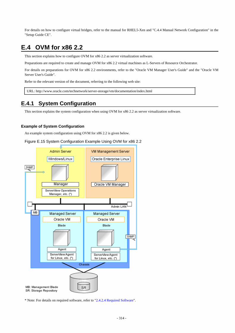
For details on how to configure virtual bridges, refer to the manual for RHEL5-Xen and "C.4.4 Manual Network Configuration" in the"Setup Guide CE".
E.4 OVM for x86 2.2This section explains how to configure OVM for x86 2.2 as server virtualization software.
Preparations are required to create and manage OVM for x86 2.2 virtual machines as L-Servers of Resource Orchestrator.
For details on preparations for OVM for x86 2.2 environments, refer to the "Oracle VM Manager User's Guide" and the "Oracle VMServer User's Guide".
Refer to the relevant version of the document, referring to the following web site:
URL: http://www.oracle.com/technetwork/server-storage/vm/documentation/index.html
E.4.1 System ConfigurationThis section explains the system configuration when using OVM for x86 2.2 as server virtualization software.
Example of System Configuration
An example system configuration using OVM for x86 2.2 is given below.
Figure E.15 System Configuration Example Using OVM for x86 2.2
* Note: For details on required software, refer to "2.4.2.4 Required Software".
- 314 -
Simplifying Network Settings
Network settings can be easily configured by Resource Orchestrator when creating L-Servers.
Depending on the conditions, such as hardware (blade servers or rack mount servers) and the presence or absence of network redundancyfor L-Servers, the setting ranges of networks differ.
For details, refer to "2.2.7 Simplifying Networks".
E.4.2 Preparations for ServersIn addition to the operations in "Chapter 8 Defining and Configuring the Server Environment", the following operations are necessary.
- Configure VIOM
When using I/O virtualization, configuration of VIOM is necessary.
- Install and configure Oracle VM Server for x86
When installing an OS on a physical server, refer to the server virtualization software manual.
When installing a VM host on an L-Server, refer to "Appendix D Installing VM Hosts on Physical L-Servers" in the "Setup GuideCE".
- Install and configure Oracle VM Manager
Necessary for management of VM hosts and L-Servers.
- Configure server pools
Configure the server pool that contains the VM host used as the L-Server location.
For details on the configurations of server pools, refer to the "Oracle VM Server User's Guide".
- Design and configure high availability
When performing redundancy of L-Servers, enable high availability for the server pool.
- Configure SSH connection
Perform configuration to enable SSH connections from the admin server of Resource Orchestrator to the VM host using the adminLAN.
E.4.3 Storage Preparations
Supported Storage Configurations
The supported storage configurations are as follow:
- Storage supported by OVM for x86 2.2
For details on the storage supported by OVM for x86 2.2, refer to the Oracle VM manual.
Preparations for Storage Environments
Check the following:
- Volumes (LUN) to allocate to domain 0 have been already created
The LUN must be larger than the size to allocate to the L-Server.
- Zoning and affinity have been set
- 315 -
Information
The infrastructure administrator registers VM management product and VM host's agents. Then, root storage repository is detected as avirtual storage resource.
The root storage repository name is used for the virtual storage resource name. However, when characters other than the following areincluded in the root storage repository name, they are replaced with hyphens ("-").
When this product manages two or more Oracle VM Managers, there may be multiple root storage repositories with the same name. Inthat case, the form of virtual storage resource names is the root storage repository name + "_" + serial number (Example: "_1").
- Numerals (0 to 9)
- Alphabetical characters: upper case (A to Z), lower case (a to z)
- Hyphens ("-") and underscores ("_")
E.4.4 Network PreparationsCheck the following:
- The configuration for the admin and public LANs has been designed
- The network environment for the admin LAN is configured
- The VLAN ID to allocate to the network resource has been configured
- The virtual bridge has been configured beforehand
When Using IBP
When using virtual L-Servers, connect the IBP uplink sets used for the public LAN and admin LAN to the VM host regardless of VIOM,after creating each IBP uplink set. It is not necessary to use the same name for the uplink set and the name of the network resource.
Creating a Virtual Bridge
A virtual bridge is required on domain 0, in order to connect the L-Server to the network.
The virtual bridge is configured by default. When changing the settings, refer to the "Oracle VM Server User's Guide" and "C.5.4 ManualNetwork Configuration" in the "Setup Guide CE".
E.5 RHEL-KVMThis section explains how to configure RHEL-KVM as server virtualization software.
Pre-setup preparations are required to create and manage RHEL-KVM virtual machines as L-Servers of Resource Orchestrator.
For details on pre-setup preparations for RHEL-KVM environments, refer to the RHEL-KVM manual.
- Red Hat Enterprise Linux 6 Virtualization Administration Guide
- Red Hat Enterprise Linux 6 Virtualization Getting Started Guide
- Red Hat Enterprise Linux 6 Virtualization Host Configuration and Guest Installation Guide
URL: https://access.redhat.com/site/documentation/en-US/Red_Hat_Enterprise_Linux/index.html
E.5.1 System ConfigurationThis section explains the system configuration necessary when using RHEL-KVM as server virtualization software.
- 316 -
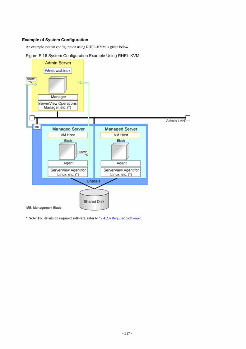
Example of System Configuration
An example system configuration using RHEL-KVM is given below.
Figure E.16 System Configuration Example Using RHEL-KVM
* Note: For details on required software, refer to "2.4.2.4 Required Software".
- 317 -

Figure E.17 System Configuration Example Using RHEL-KVM (When Using a NAS Configuration)
* Note: For details on required software, refer to "2.4.2.4 Required Software".
- 318 -
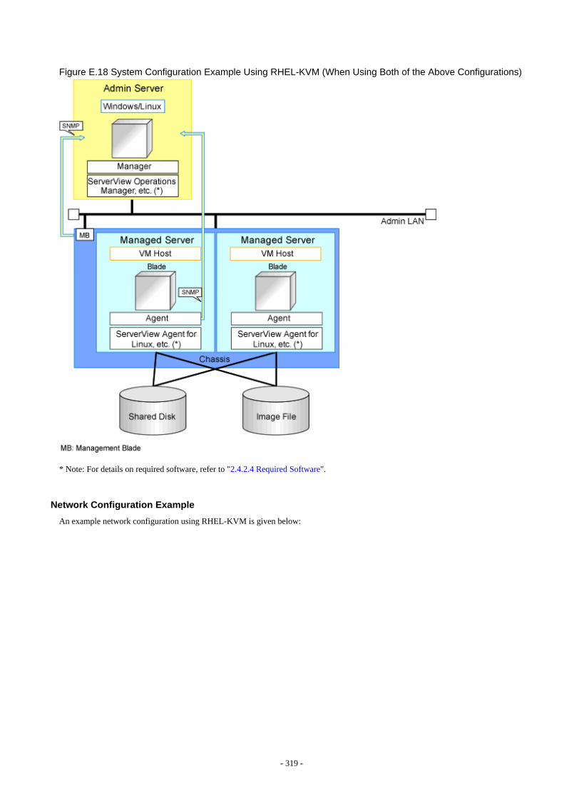
Figure E.18 System Configuration Example Using RHEL-KVM (When Using Both of the Above Configurations)
* Note: For details on required software, refer to "2.4.2.4 Required Software".
Network Configuration Example
An example network configuration using RHEL-KVM is given below:
- 319 -

Figure E.19 Virtual Bridge Settings Using Network Resources
L-Server Creation Procedure
The procedure for creating L-Servers is shown below.
- 320 -
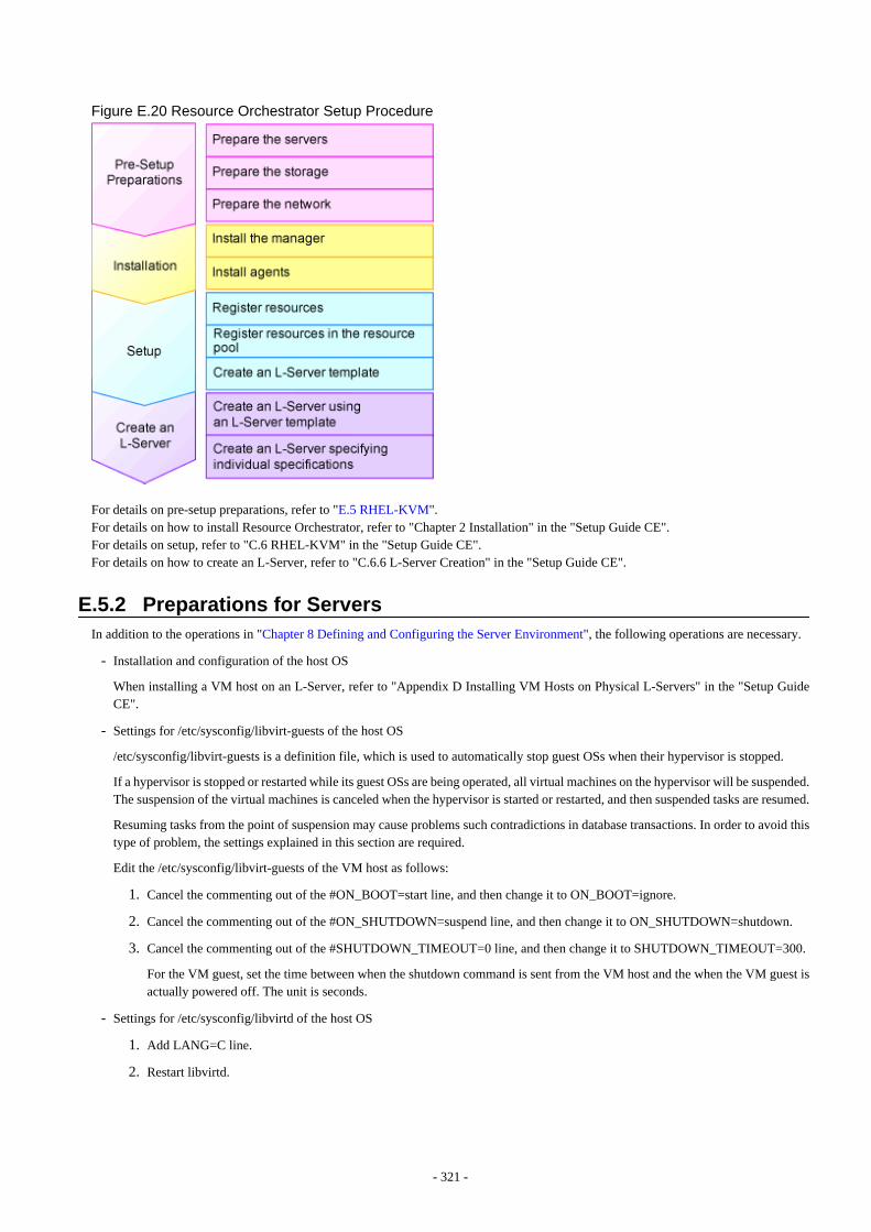
Figure E.20 Resource Orchestrator Setup Procedure
For details on pre-setup preparations, refer to "E.5 RHEL-KVM".For details on how to install Resource Orchestrator, refer to "Chapter 2 Installation" in the "Setup Guide CE".For details on setup, refer to "C.6 RHEL-KVM" in the "Setup Guide CE".For details on how to create an L-Server, refer to "C.6.6 L-Server Creation" in the "Setup Guide CE".
E.5.2 Preparations for ServersIn addition to the operations in "Chapter 8 Defining and Configuring the Server Environment", the following operations are necessary.
- Installation and configuration of the host OS
When installing a VM host on an L-Server, refer to "Appendix D Installing VM Hosts on Physical L-Servers" in the "Setup GuideCE".
- Settings for /etc/sysconfig/libvirt-guests of the host OS
/etc/sysconfig/libvirt-guests is a definition file, which is used to automatically stop guest OSs when their hypervisor is stopped.
If a hypervisor is stopped or restarted while its guest OSs are being operated, all virtual machines on the hypervisor will be suspended.The suspension of the virtual machines is canceled when the hypervisor is started or restarted, and then suspended tasks are resumed.
Resuming tasks from the point of suspension may cause problems such contradictions in database transactions. In order to avoid thistype of problem, the settings explained in this section are required.
Edit the /etc/sysconfig/libvirt-guests of the VM host as follows:
1. Cancel the commenting out of the #ON_BOOT=start line, and then change it to ON_BOOT=ignore.
2. Cancel the commenting out of the #ON_SHUTDOWN=suspend line, and then change it to ON_SHUTDOWN=shutdown.
3. Cancel the commenting out of the #SHUTDOWN_TIMEOUT=0 line, and then change it to SHUTDOWN_TIMEOUT=300.
For the VM guest, set the time between when the shutdown command is sent from the VM host and the when the VM guest isactually powered off. The unit is seconds.
- Settings for /etc/sysconfig/libvirtd of the host OS
1. Add LANG=C line.
2. Restart libvirtd.
- 321 -
Note
- Version check and upgrade of libvirt packages
Check if the version of the libvirt package of the Host OS is 0.9.4-23.el6_2.4 or later.
The libvirt package contains some security incompatibilities.
If the package is an earlier version, upgrade it.
For details, refer to the following web site.
URL: https://access.redhat.com/knowledge/solutions/71283
- When using RHEL6.4 or later on a VM host, check if each of the following packages is the version listed below or a later one. Ifthe package is an earlier version, upgrade it.
- augeas-0.9.0-4.el6.x86_64.rpm
- libvirt-0.10.2-18.el6_4.5.x86_64.rpm
- libvirt-client-0.10.2-18.el6_4.5.x86_64.rpm
- libvirt-debuginfo-0.10.2-18.el6_4.5.x86_64.rpm
- libvirt-devel-0.10.2-18.el6_4.5.x86_64.rpm
- libvirt-lock-sanlock-0.10.2-18.el6_4.5.x86_64.rpm
- libvirt-python-0.10.2-18.el6_4.5.x86_64.rpm
- sanlock-2.6-2.el6.x86_64.rpm
- sanlock-lib-2.6-2.el6.x86_64.rpm
There is a problem with libvirt. For details, refer to the following:
URL: https://bugzilla.redhat.com/show_bug.cgi?id=953107
- Configuration of SSH connection
Configure VM hosts so that the admin server can establish SSH connections to them through admin LANs.When configuring the SSH of VM hosts, make "3DES-CBC" usable as an encryption algorithm.This configuration is necessary for the dashboard (System Conditions) to collect information.
An example configuration procedure is shown below. (the example uses OpenSSH, which is bundled with the OS):
1. Add "3des-cbc" to Ciphers in /etc/ssh/sshd_config.
Note: If Ciphers does not exist or is commented out, this addition is not necessary."3DES-CBC" is enabled by default.
2. Restart the SSH daemon.
# /etc/rc2.d/S55sshd restart
Prerequisites for L-Server Migration
Prerequisites for virtual L-Server live/cold migration in RHEL-KVM environments are described as follows:
- The following items for the source and destination VM hosts for migration must be the same
- Kernel versions (including minor versions)
These prerequisites are necessary for live migration.
- CPU architectures (Intel64 or x86)
- CPU model names
- The disk used for a virtual L-Server must be connected to the destination VM host
- 322 -
- The virtual bridge connected to a virtual L-Server must be in the destination VM host.
Configuration for L-Server Live Migration
When using Resource Orchestrator in RHEL-KVM environments, SSH is used for virtual L-Server live migration.
The following settings must be configured in each host which performs live migration of L-Servers, using the manager.
- /etc/hosts configuration
- configuration when using SSH
Refer to the following sections in the "Red Hat Enterprise Linux 6 Virtualization Administration Guide", and configure the settings.
- Chapter 5. KVM live migration
- Chapter 6. Remote management of guests
URL: http://docs.redhat.com/docs/en-US/Red_Hat_Enterprise_Linux/6/html/Virtualization_Administration_Guide/index.html
The manuals for Red Hat Enterprise Linux can be referred to from the following URL.
URL: https://access.redhat.com/site/documentation/en-US/Red_Hat_Enterprise_Linux/index.html
Configuration of Swap Area for the Host OS
When there is insufficient swap area for the Host OS, the virtual L-Server may fail to start. Be sure to configure it appropriately.
For details, refer to the following section in the "Red Hat Enterprise Linux 6 Virtualization Administration Guide".
Chapter 7. Overcommitting with KVM
7.1. Introduction
URL:https://access.redhat.com/site/documentation/en-US/Red_Hat_Enterprise_Linux/6/html/Virtualization_Administration_Guide/chap-Virtualization-Tips_and_tricks-Overcommitting_with_KVM.html
When it is difficult to secure sufficient swap area, it is also possible to configure the kernel parameters (/proc/sys/vm/overcommit_memory)to avoid failure of start operations due to a lack of virtual L-Server memory space.
For details, refer to the following section in the "Red Hat Enterprise Linux 6 Performance Tuning Guide".
Chapter 5. Memory
5.4. Capacity Tuning
URL:https://access.redhat.com/site/documentation/en-US/Red_Hat_Enterprise_Linux/6/html/Performance_Tuning_Guide/s-memory-captun.html
Configuration for Red Hat DM Multipath
Edit the /etc/multipath.conf configuration file, and perform the following:
- Set the user_friendly_names attribute to "yes".
- Do not set the alias attribute.
- Leave other settings at their default values.
For details, refer to the following RedHat document:
- 323 -
URL: https://access.redhat.com/knowledge/docs/en-US/Red_Hat_Enterprise_Linux/6/html/DM_Multipath/index.html
The manuals for Red Hat Enterprise Linux can be referred to from the following URL.
URL: https://access.redhat.com/site/documentation/en-US/Red_Hat_Enterprise_Linux/index.html
E.5.3 Storage Preparations
Supported Storage Configurations
- Storage supported by KVM
For details on the storage supported by KVM, refer to the KVM manual
- The method involving allocation of storage to VM guests supports only the following:
Entire Block Devices (such as LUN)
Due to specification changes to libvirt, when LVM partitions or physical disk partitions are allocated to a VM guest, SG_IO on theguest OS cannot be issued.Resource Orchestrator only supports the method involving allocation of entire block devices, which allows SG_IO to be issued fromthe guest OS.
For details, refer to the following section in the "Virtualization Host Configuration and Guest Installation Guide".
- 6.1. Guest virtual machine prerequisites and considerations
URL:https://access.redhat.com/site/documentation/en-US/Red_Hat_Enterprise_Linux/6/html/Virtualization_Host_Configuration_and_Guest_Installation_Guide/index.html
Note
It is not possible to allocate physical disk partitions and LVM partitions to virtual L-Servers as disk resources created in advance.
Preparations for Storage Environments
Check the following:
- Volumes (LUNs) to assign to the virtual L-Server have already been created
LUNs are used for virtual L-Server disks. Create the same number of LUNs as the number of necessary disks. The size of each LUNmust be larger than the size of each disk.
- Volumes (LUN) to allocate to cloning images have been already created
Cloning images are stored on LUNs. Create LUNs based on the number of cloning images to be created. The size of each LUN mustbe larger than the size of each cloning image.
- Zoning and affinity have been set
When migrating VM guests for Virtual L-Servers, configure zoning and affinity, and set LUNs as shared disks.
E.5.4 Preparations for Storage Environments (NAS Configurations)In NAS configurations, libvirt storage pools are used.
This section explains the preparations for such environments.
Supported libvirt Storage Pool Configurations
The supported configuration is as follows:
- 324 -
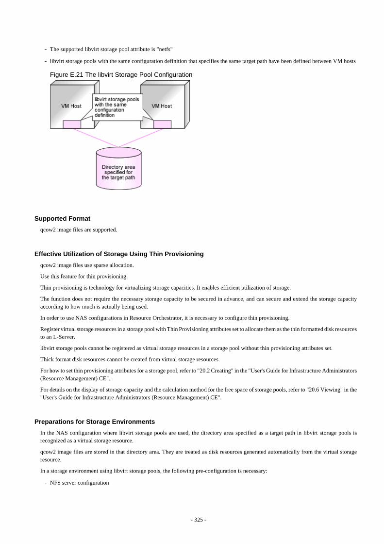
- The supported libvirt storage pool attribute is "netfs"
- libvirt storage pools with the same configuration definition that specifies the same target path have been defined between VM hosts
Figure E.21 The libvirt Storage Pool Configuration
Supported Format
qcow2 image files are supported.
Effective Utilization of Storage Using Thin Provisioning
qcow2 image files use sparse allocation.
Use this feature for thin provisioning.
Thin provisioning is technology for virtualizing storage capacities. It enables efficient utilization of storage.
The function does not require the necessary storage capacity to be secured in advance, and can secure and extend the storage capacityaccording to how much is actually being used.
In order to use NAS configurations in Resource Orchestrator, it is necessary to configure thin provisioning.
Register virtual storage resources in a storage pool with Thin Provisioning attributes set to allocate them as the thin formatted disk resourcesto an L-Server.
libvirt storage pools cannot be registered as virtual storage resources in a storage pool without thin provisioning attributes set.
Thick format disk resources cannot be created from virtual storage resources.
For how to set thin provisioning attributes for a storage pool, refer to "20.2 Creating" in the "User's Guide for Infrastructure Administrators(Resource Management) CE".
For details on the display of storage capacity and the calculation method for the free space of storage pools, refer to "20.6 Viewing" in the"User's Guide for Infrastructure Administrators (Resource Management) CE".
Preparations for Storage Environments
In the NAS configuration where libvirt storage pools are used, the directory area specified as a target path in libvirt storage pools isrecognized as a virtual storage resource.
qcow2 image files are stored in that directory area. They are treated as disk resources generated automatically from the virtual storageresource.
In a storage environment using libvirt storage pools, the following pre-configuration is necessary:
- NFS server configuration
- 325 -
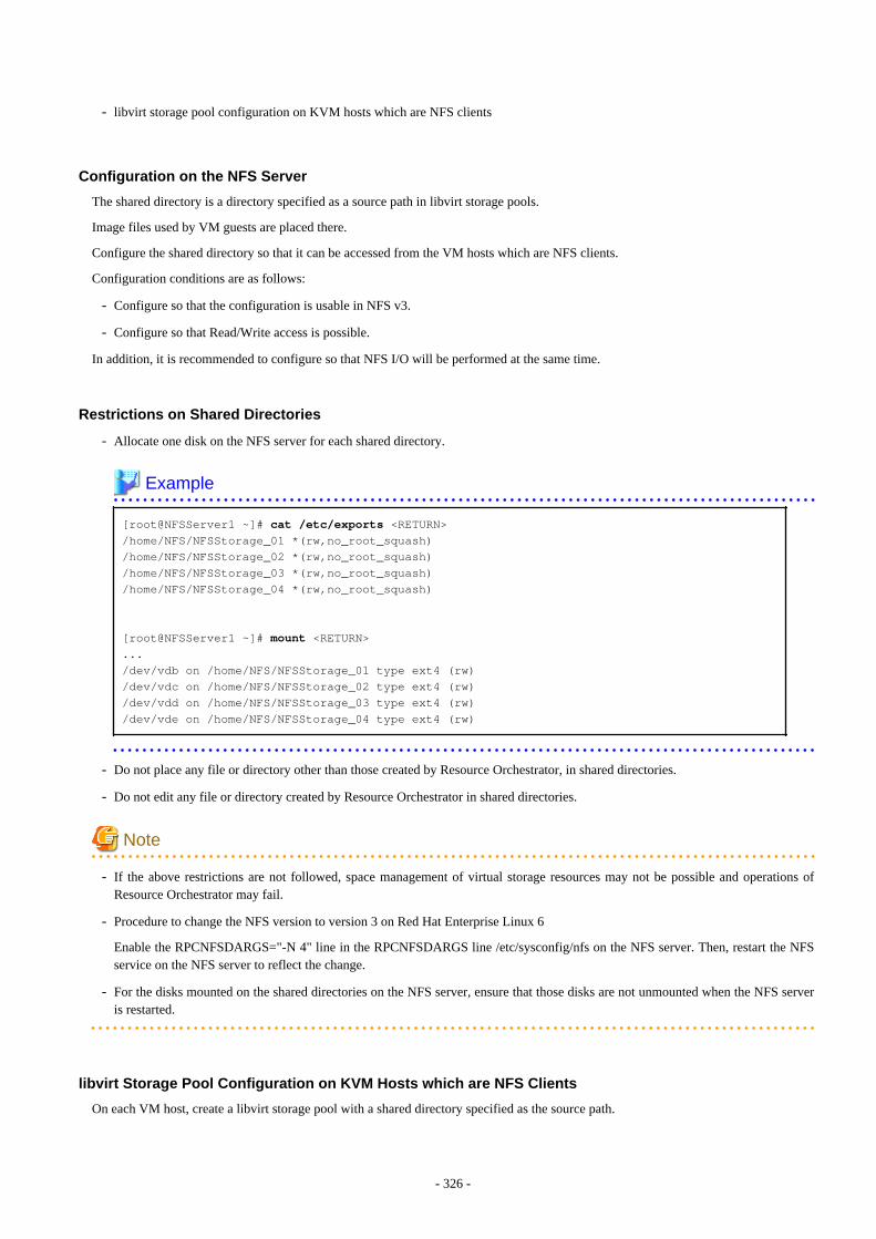
- libvirt storage pool configuration on KVM hosts which are NFS clients
Configuration on the NFS Server
The shared directory is a directory specified as a source path in libvirt storage pools.
Image files used by VM guests are placed there.
Configure the shared directory so that it can be accessed from the VM hosts which are NFS clients.
Configuration conditions are as follows:
- Configure so that the configuration is usable in NFS v3.
- Configure so that Read/Write access is possible.
In addition, it is recommended to configure so that NFS I/O will be performed at the same time.
Restrictions on Shared Directories
- Allocate one disk on the NFS server for each shared directory.
Example [root@NFSServer1 ~]# cat /etc/exports <RETURN>/home/NFS/NFSStorage_01 *(rw,no_root_squash)/home/NFS/NFSStorage_02 *(rw,no_root_squash)/home/NFS/NFSStorage_03 *(rw,no_root_squash)/home/NFS/NFSStorage_04 *(rw,no_root_squash)
[root@NFSServer1 ~]# mount <RETURN>.../dev/vdb on /home/NFS/NFSStorage_01 type ext4 (rw)/dev/vdc on /home/NFS/NFSStorage_02 type ext4 (rw)/dev/vdd on /home/NFS/NFSStorage_03 type ext4 (rw)/dev/vde on /home/NFS/NFSStorage_04 type ext4 (rw)
- Do not place any file or directory other than those created by Resource Orchestrator, in shared directories.
- Do not edit any file or directory created by Resource Orchestrator in shared directories.
Note
- If the above restrictions are not followed, space management of virtual storage resources may not be possible and operations ofResource Orchestrator may fail.
- Procedure to change the NFS version to version 3 on Red Hat Enterprise Linux 6
Enable the RPCNFSDARGS="-N 4" line in the RPCNFSDARGS line /etc/sysconfig/nfs on the NFS server. Then, restart the NFSservice on the NFS server to reflect the change.
- For the disks mounted on the shared directories on the NFS server, ensure that those disks are not unmounted when the NFS serveris restarted.
libvirt Storage Pool Configuration on KVM Hosts which are NFS Clients
On each VM host, create a libvirt storage pool with a shared directory specified as the source path.
- 326 -
When doing so, ensure that settings for the following items in the configuration definition for the libvirt storage pool are the same on eachVM host:
- Name(1)
- uuid(2)
- NFS Server IP(3)
- Source Path(4)
- Target Path(5)
Note
Do not include the following characters in the settings of the above items. If any of the following characters is included, that storage poolcannot be detected as a virtual storage resource.
- Blank spaces (" ")
- Double-byte characters
- Yen marks ("\")
- Double quotes (""")
- Single quotes ("'")
- Semicolons (";")
- Parenthesis ("()")
Example
An example of the configuration definition for a libvirt storage pool is given below:
<pool type='netfs'> <name>rcxnfs</name>(1) <uuid>bd0a2edc-66fb-e630-d2c9-cafc85a9cd29</uuid>(2) <capacity>52844822528</capacity> <allocation>44229459968</allocation> <available>8615362560</available> <source> <host name='192.168.1.1'/>(3) <dir path='/root/rcx_nfs'/>(4) <format type='nfs'/> </source> <target> <path>/root/rcx_lib_pool</path>(5) <permissions> <mode>0700</mode> <owner>-1</owner> <group>-1</group> </permissions> </target></pool>
- 327 -
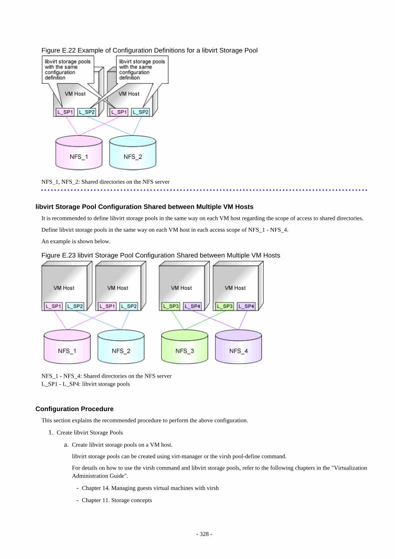
Figure E.22 Example of Configuration Definitions for a libvirt Storage Pool
NFS_1, NFS_2: Shared directories on the NFS server
libvirt Storage Pool Configuration Shared between Multiple VM Hosts
It is recommended to define libvirt storage pools in the same way on each VM host regarding the scope of access to shared directories.
Define libvirt storage pools in the same way on each VM host in each access scope of NFS_1 - NFS_4.
An example is shown below.
Figure E.23 libvirt Storage Pool Configuration Shared between Multiple VM Hosts
NFS_1 - NFS_4: Shared directories on the NFS serverL_SP1 - L_SP4: libvirt storage pools
Configuration Procedure
This section explains the recommended procedure to perform the above configuration.
1. Create libvirt Storage Pools
a. Create libvirt storage pools on a VM host.
libvirt storage pools can be created using virt-manager or the virsh pool-define command.
For details on how to use the virsh command and libvirt storage pools, refer to the following chapters in the "VirtualizationAdministration Guide".
- Chapter 14. Managing guests virtual machines with virsh
- Chapter 11. Storage concepts
- 328 -
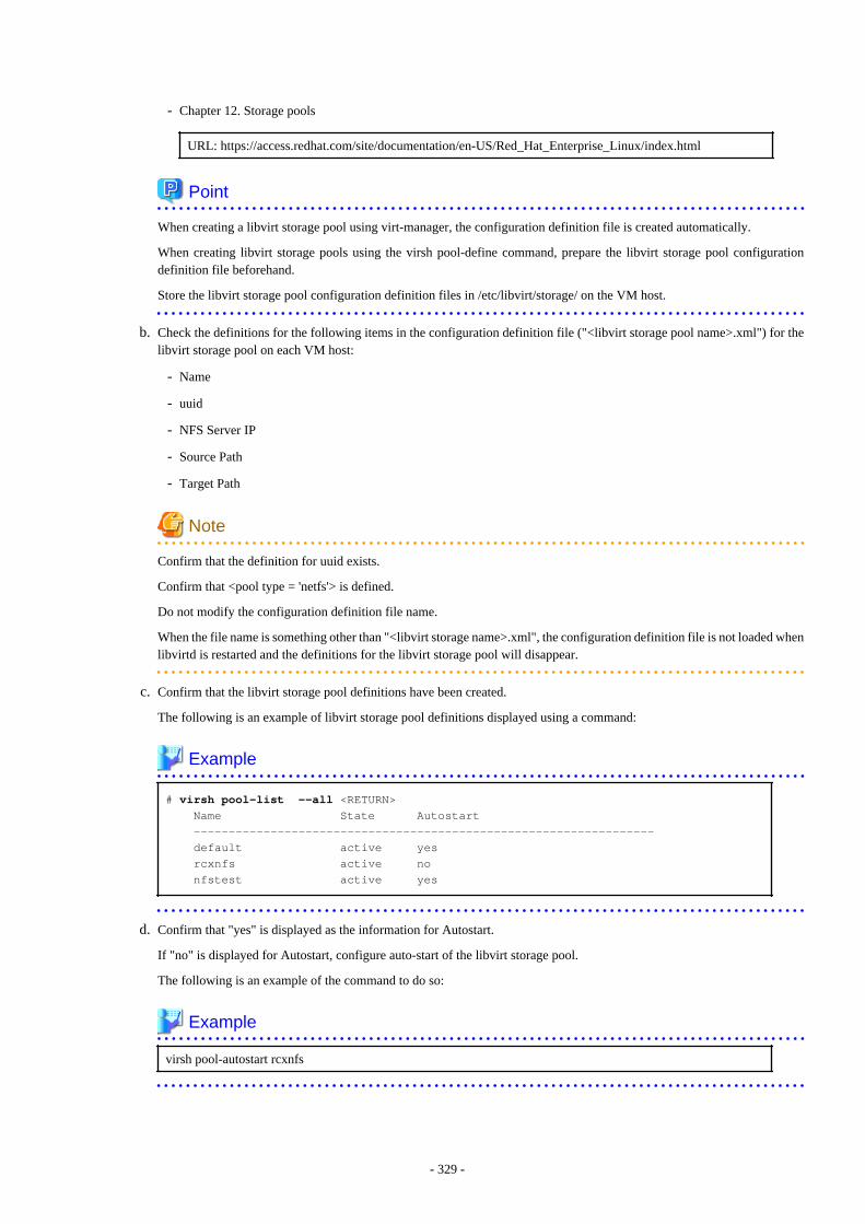
- Chapter 12. Storage pools
URL: https://access.redhat.com/site/documentation/en-US/Red_Hat_Enterprise_Linux/index.html
Point
When creating a libvirt storage pool using virt-manager, the configuration definition file is created automatically.
When creating libvirt storage pools using the virsh pool-define command, prepare the libvirt storage pool configurationdefinition file beforehand.
Store the libvirt storage pool configuration definition files in /etc/libvirt/storage/ on the VM host.
b. Check the definitions for the following items in the configuration definition file ("<libvirt storage pool name>.xml") for thelibvirt storage pool on each VM host:
- Name
- uuid
- NFS Server IP
- Source Path
- Target Path
Note
Confirm that the definition for uuid exists.
Confirm that <pool type = 'netfs'> is defined.
Do not modify the configuration definition file name.
When the file name is something other than "<libvirt storage name>.xml", the configuration definition file is not loaded whenlibvirtd is restarted and the definitions for the libvirt storage pool will disappear.
c. Confirm that the libvirt storage pool definitions have been created.
The following is an example of libvirt storage pool definitions displayed using a command:
Example # virsh pool-list --all <RETURN> Name State Autostart ------------------------------------------------------------------ default active yes rcxnfs active no nfstest active yes
d. Confirm that "yes" is displayed as the information for Autostart.
If "no" is displayed for Autostart, configure auto-start of the libvirt storage pool.
The following is an example of the command to do so:
Example
virsh pool-autostart rcxnfs
- 329 -
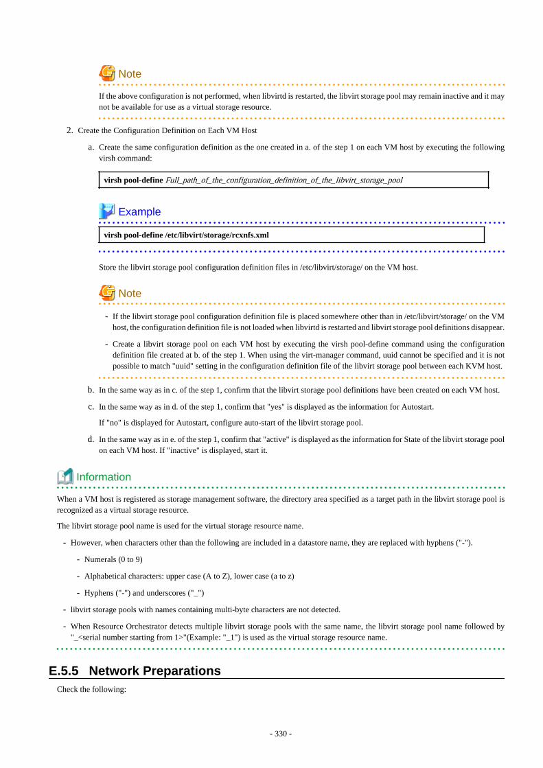
Note
If the above configuration is not performed, when libvirtd is restarted, the libvirt storage pool may remain inactive and it maynot be available for use as a virtual storage resource.
2. Create the Configuration Definition on Each VM Host
a. Create the same configuration definition as the one created in a. of the step 1 on each VM host by executing the followingvirsh command:
virsh pool-define Full_path_of_the_configuration_definition_of_the_libvirt_storage_pool
Example
virsh pool-define /etc/libvirt/storage/rcxnfs.xml
Store the libvirt storage pool configuration definition files in /etc/libvirt/storage/ on the VM host.
Note
- If the libvirt storage pool configuration definition file is placed somewhere other than in /etc/libvirt/storage/ on the VMhost, the configuration definition file is not loaded when libvirtd is restarted and libvirt storage pool definitions disappear.
- Create a libvirt storage pool on each VM host by executing the virsh pool-define command using the configurationdefinition file created at b. of the step 1. When using the virt-manager command, uuid cannot be specified and it is notpossible to match "uuid" setting in the configuration definition file of the libvirt storage pool between each KVM host.
b. In the same way as in c. of the step 1, confirm that the libvirt storage pool definitions have been created on each VM host.
c. In the same way as in d. of the step 1, confirm that "yes" is displayed as the information for Autostart.
If "no" is displayed for Autostart, configure auto-start of the libvirt storage pool.
d. In the same way as in e. of the step 1, confirm that "active" is displayed as the information for State of the libvirt storage poolon each VM host. If "inactive" is displayed, start it.
Information
When a VM host is registered as storage management software, the directory area specified as a target path in the libvirt storage pool isrecognized as a virtual storage resource.
The libvirt storage pool name is used for the virtual storage resource name.
- However, when characters other than the following are included in a datastore name, they are replaced with hyphens ("-").
- Numerals (0 to 9)
- Alphabetical characters: upper case (A to Z), lower case (a to z)
- Hyphens ("-") and underscores ("_")
- libvirt storage pools with names containing multi-byte characters are not detected.
- When Resource Orchestrator detects multiple libvirt storage pools with the same name, the libvirt storage pool name followed by"_<serial number starting from 1>"(Example: "_1") is used as the virtual storage resource name.
E.5.5 Network PreparationsCheck the following:
- 330 -
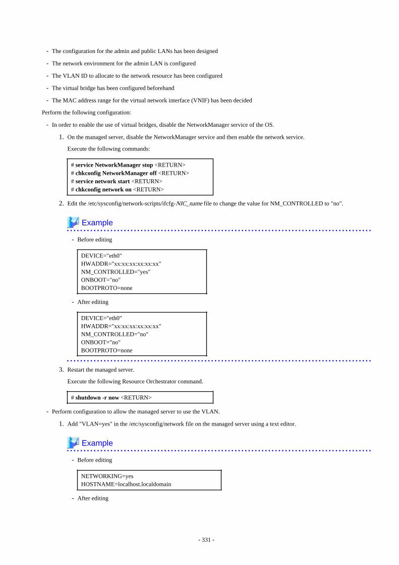
- The configuration for the admin and public LANs has been designed
- The network environment for the admin LAN is configured
- The VLAN ID to allocate to the network resource has been configured
- The virtual bridge has been configured beforehand
- The MAC address range for the virtual network interface (VNIF) has been decided
Perform the following configuration:
- In order to enable the use of virtual bridges, disable the NetworkManager service of the OS.
1. On the managed server, disable the NetworkManager service and then enable the network service.
Execute the following commands:
# service NetworkManager stop <RETURN># chkconfig NetworkManager off <RETURN># service network start <RETURN># chkconfig network on <RETURN>
2. Edit the /etc/sysconfig/network-scripts/ifcfg-NIC_name file to change the value for NM_CONTROLLED to "no".
Example
- Before editing
DEVICE="eth0"HWADDR="xx:xx:xx:xx:xx:xx"NM_CONTROLLED="yes"ONBOOT="no"BOOTPROTO=none
- After editing
DEVICE="eth0"HWADDR="xx:xx:xx:xx:xx:xx"NM_CONTROLLED="no"ONBOOT="no"BOOTPROTO=none
3. Restart the managed server.
Execute the following Resource Orchestrator command.
# shutdown -r now <RETURN>
- Perform configuration to allow the managed server to use the VLAN.
1. Add "VLAN=yes" in the /etc/sysconfig/network file on the managed server using a text editor.
Example
- Before editing
NETWORKING=yesHOSTNAME=localhost.localdomain
- After editing
- 331 -
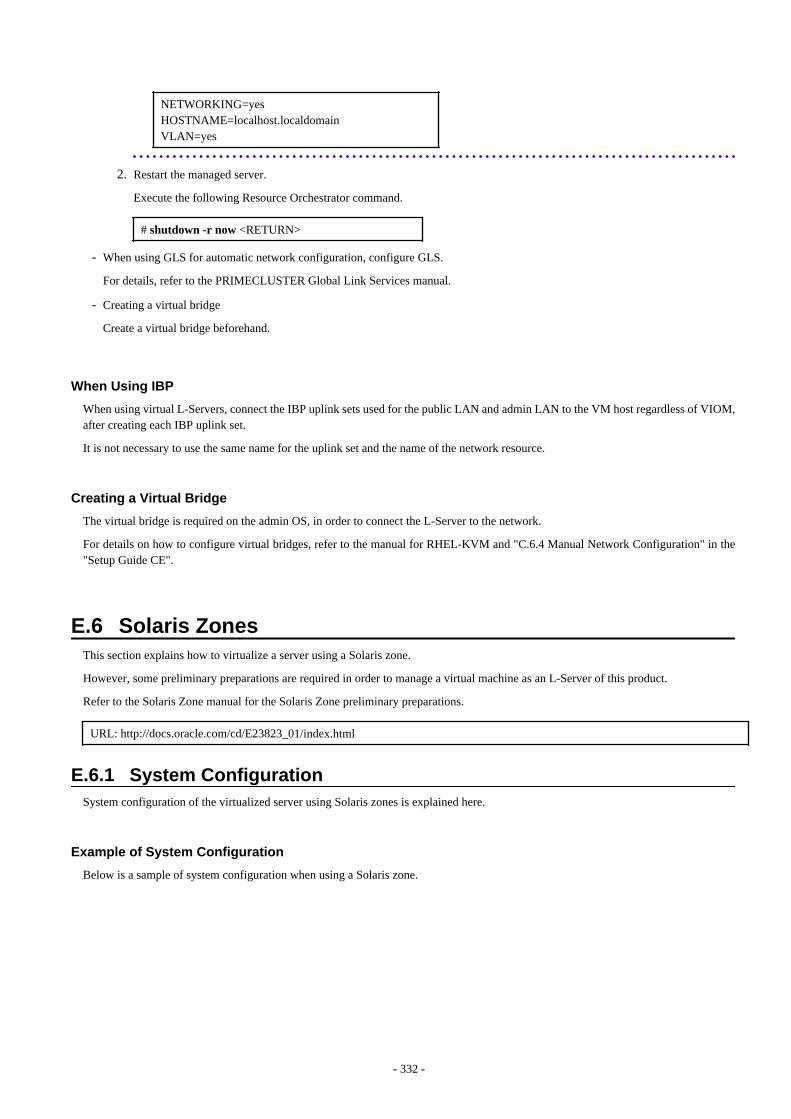
NETWORKING=yesHOSTNAME=localhost.localdomainVLAN=yes
2. Restart the managed server.
Execute the following Resource Orchestrator command.
# shutdown -r now <RETURN>
- When using GLS for automatic network configuration, configure GLS.
For details, refer to the PRIMECLUSTER Global Link Services manual.
- Creating a virtual bridge
Create a virtual bridge beforehand.
When Using IBP
When using virtual L-Servers, connect the IBP uplink sets used for the public LAN and admin LAN to the VM host regardless of VIOM,after creating each IBP uplink set.
It is not necessary to use the same name for the uplink set and the name of the network resource.
Creating a Virtual Bridge
The virtual bridge is required on the admin OS, in order to connect the L-Server to the network.
For details on how to configure virtual bridges, refer to the manual for RHEL-KVM and "C.6.4 Manual Network Configuration" in the"Setup Guide CE".
E.6 Solaris ZonesThis section explains how to virtualize a server using a Solaris zone.
However, some preliminary preparations are required in order to manage a virtual machine as an L-Server of this product.
Refer to the Solaris Zone manual for the Solaris Zone preliminary preparations.
URL: http://docs.oracle.com/cd/E23823_01/index.html
E.6.1 System ConfigurationSystem configuration of the virtualized server using Solaris zones is explained here.
Example of System Configuration
Below is a sample of system configuration when using a Solaris zone.
- 332 -
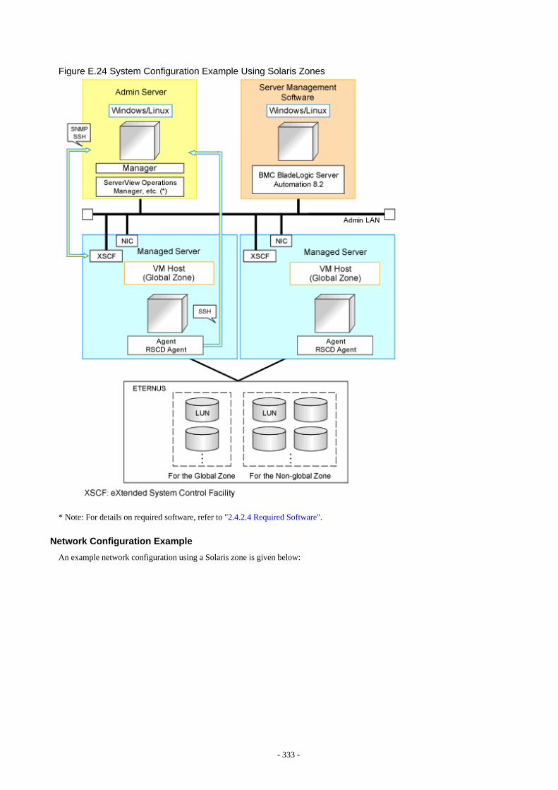
Figure E.24 System Configuration Example Using Solaris Zones
* Note: For details on required software, refer to "2.4.2.4 Required Software".
Network Configuration Example
An example network configuration using a Solaris zone is given below:
- 333 -
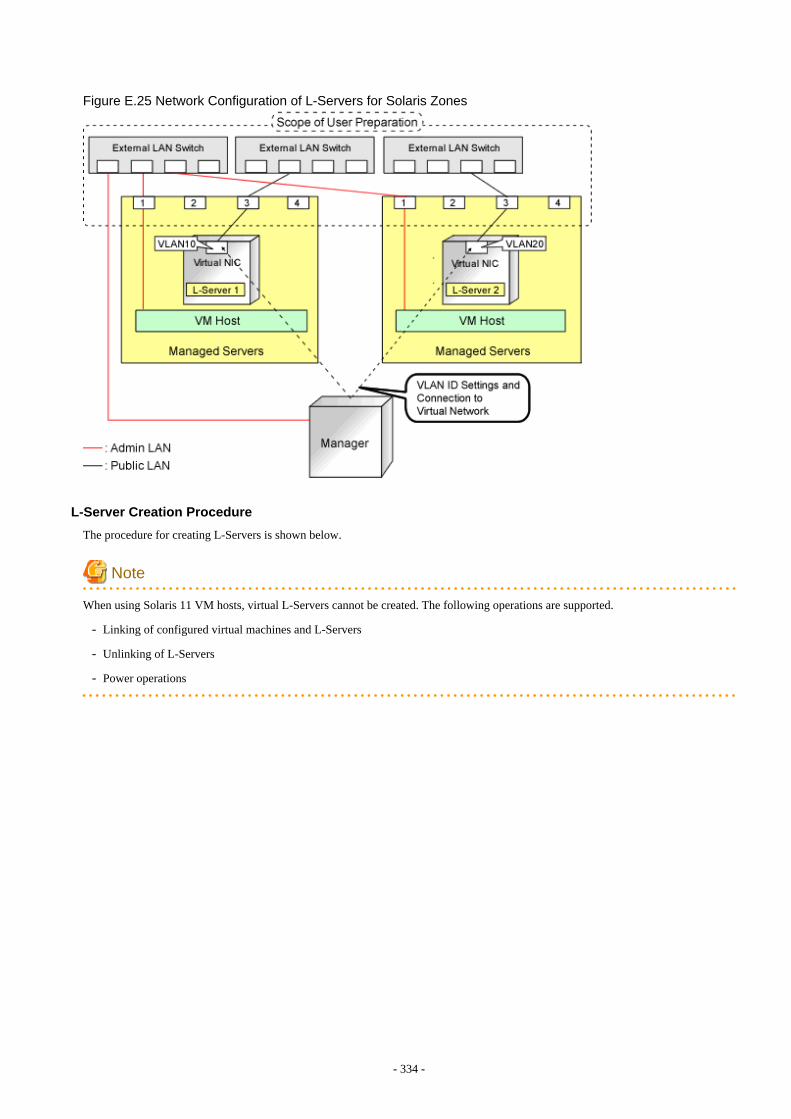
Figure E.25 Network Configuration of L-Servers for Solaris Zones
L-Server Creation Procedure
The procedure for creating L-Servers is shown below.
Note
When using Solaris 11 VM hosts, virtual L-Servers cannot be created. The following operations are supported.
- Linking of configured virtual machines and L-Servers
- Unlinking of L-Servers
- Power operations
- 334 -

Figure E.26 Resource Orchestrator Setup Procedure
For details on pre-setup preparations, refer to "E.6 Solaris Zones".For details on how to install Resource Orchestrator, refer to "Chapter 2 Installation" in the "Setup Guide CE".For details on setup, refer to "C.7 Solaris Zones" in the "Setup Guide CE".For details on how to create an L-Server, refer to "C.7.6 Creating an L-Server" in the "Setup Guide CE".
E.6.2 Preparations for ServersThe following procedures are required.
When you create Solaris zones on the OVM for SPARC guest domain, consider the guest domain to be a global zone, and design in thesame way to create a global zone on a physical server.
- Installation and configuration of the admin OS
Install and configure the global zone.
When the OS of a VM host is Solaris10, use UFS as the file system.
Set SSH access permission, and enable password authentication for accounts with administrator privileges.
When mounting a pool on a system, resources are classified using their settings.
Create pools with configurations that give consideration to operation with reduced hardware.
This configuration is necessary to obtain information of Virtual L-Servers and VM guests and perform power operation of them.
When the Logical Domains Manager daemon is enabled, VM hosts can be registered as Solaris Zones by configuring the definitionfiles. For details, refer to "Chapter 8 Creating Definition Files" in the "Setup Guide CE".
- Create the Solaris Zone resource pool
Create the Solaris Zone resource pool for the global zone and the non-global zone.
The resource pools of Solaris Zones are referred to as Solaris Zone resource pools.
If this product is used for managing resources, create a resource pool for the non-global zone only, and name the resource pool"pool_resource".
The resource pool name can be changed.
For details, refer to "C.7 Solaris Zones" in the "Setup Guide CE".
It is necessary to enable the target resource pool's service.
- 335 -
- Set the capping of CPU and capping of the memory for the non-global zone
Already created non-global zones will be the target of resource management when the capping value is set.
The capping supported with this product is as follows.
- CPU capping
zone.cpu-cap
- Memory capping
rcapd
This product does not show the capping value applied to the running non-global zone (using the prctl command) but configurationinformation of the non-global zone.
Therefore set the zone.cpu-cap using the zonecfg command.
Design capping values based on the estimated resource usage of a non-global zone.
When the non-global zone uses resources beyond capping, it will have impact on system performance.
Please refer to the relevant version of the document, referring to the following URL:
Oracle corporation
URL: http://www.oracle.com/index.html
- When the non-global zone is the target of resource management, the amount of resources of this product is calculated as follows:
- CPU capping
Number of CPUs = capping of CPUs / 100 (if there is a decimal value, round it up)
CPU performance = (capping of CPUs / (number of CPUs * 100)) * performance of physical CPUs(GHz)
Example
- When capping of CPUs is 720 and performance of physical CPUs is 3.0GHz
Number of CPUs = 720 / 100 (rounded up) = 8
CPU performance = (720 / (8 * 100)) * 3.0 = 2.7(GHz)
- Memory capping
Capping of memory resources
- Install the RSCD agent
When using the function which needs BMC BladeLogic Server Automation described in "Table 11.1 Functional DifferencesDepending on Server Virtualization Software" in "11.1 Deciding Server Virtualization Software", do so using the following procedure.
1. Install the RSCD agent.
2. Enable control of the global zone of the RSCD agent.
3. Add the managed server to BladeLogic.
At this time, specify the IP address of the managed server when adding it.
For details, contact Fujitsu technical staff.
- Pre-configuration of Server Management Software
When coordinating with BMC BladeLogic Server Automation, register BMC BladeLogic Server Automation in Resource Orchestratoras server management software. Perform pre-configuration before registration.For details on pre-configuration, refer to "I.1 Coordination with BMC BladeLogic Server Automation" in the "Setup Guide CE".
- 336 -
E.6.3 Storage PreparationsThis section explains the preparations for setting up storage.
Supported Storage Configurations
The supported storage configurations are as follow:
- LUNs managed by ETERNUS
Preparations for Storage Environments
- When use disks in non-global zones, prepare a LUN for each non-global zone.
- Mount a LUN for each zone path of a non-global zone.
Configure a non-global zone in the mounted LUN.
- Configure /etc/vfstab so that LUNs corresponding to the zone paths used by virtual L-Servers will be mounted.
- For the zone path used by the virtual L-Server, provide only the owner of the directory with read, write, and execution permissions(700).
- The storage affinity switchover method can be used as a server switchover function.
For details on how to configure the server switchover, refer to "8.1.6 Settings when Switching Over Fujitsu M10/SPARC EnterpriseServers".
For details on the function, refer to "Chapter 4 Server Switchover" in the "Operation Guide VE".
- Only the server switchover function or the migration function can be used.
Perform design of the configuration based on the function that you will be using.
- When using the server switchover function, the following configurations are necessary:
- Design the area used for the non-global zone so that it can be referred to in the same way both before and after switchover.
Use the switchover SAN area for server switchover.
- When using the server switchover function, non-global zones are not automatically started.
Perform configuration so that non-global zones are automatically started when global zones are started after server switchover.
- When using the migration function, or [Relocate at startup] has been configured for the L-Server boot location, the followingconfigurations are necessary.
- Perform configuration so that LUNs corresponding to the zone paths used by virtual L-Servers will not be automaticallymounted.
- When using the migration function of this product, unmount the disk that is the migration source, and then mount the diskthat is the migration destination. At this time, the zone paths defined in the disk resource and the /etc/vfstab mount settingsfor the zone paths are used for migration.
Therefore, perform connection and setting so the disk on which a non-global zone is to be created can be mounted on boththe migration source and destination.However, do not mount it in a location other than the global zone where the non-global zone operates.
Note
- Do not execute the mounting of LUNs in other global zones when the LUN is shared from two or more global zones and the LUNcorresponds to the zone path that a virtual L-Server uses. There is a possibility that the data of the LUN will be damaged due to anaccess conflict when a virtual L-Server that uses this LUN is created.
- 337 -
E.6.4 Network PreparationsCheck the following:
- The configuration for the admin and public LANs has been designed
- The network environment for the admin LAN is configured
- A global zone is already connected to the admin LAN
- NICs to be used in the non-global zones are already designed
- The IDs for distinguishing the NICs used in the non-global zone have been designed.
When Using IBP
When using virtual L-Servers, connect the IBP uplink sets used for the public LAN and admin LAN to the VM host regardless of VIOM,after creating each IBP uplink set. It is not necessary to use the same name for the uplink set and the name of the network resource.
Designing NICs to be Used in Non-Global Zones
- When creating L-Servers using Resource Orchestrator, create a non-global zone using exclusive IP settings.
For the NICs to be used by L-Servers, design them so those NICs will not be used in the global zone or non-global zones which havealready been created.When migrating VM guests (non-global zone) between VM hosts (global zones), perform design so a NIC with the same name is usedon the source and destination.Also, design the IDs for distinguishing the NICs used by the L-Server. This value corresponds to the VLAN ID of the network resource,so please use a value between 1 and 4094.
- When associating already created non-global zones with L-Servers, there are no restrictions on the network configurations.
- When NICs for L-Servers are DHCP, place the DHCP servers, and configure the settings to allocate IP addresses to L-Servers.
- Design IP addresses to allocate to L-Servers that do not overlap with IP addresses that are not managed in Resource Orchestrator.
- The NIC hardware configurations must be the same on servers in the same pool.
E.7 OVM for SPARCThis section explains how to configure OVM for SPARC as server virtualization software.
However, some preliminary preparations are required in order to manage an OVM for SPARC virtual machine as an L-Server of thisproduct.
For details on pre-setup preparations for OVM for SPARC environments, refer to the OVM for SPARC manual.
URL: http://www.oracle.com/technetwork/server-storage/vm/documentation/index.html
E.7.1 System ConfigurationThis section explains the system configuration when using OVM for SPARC as server virtualization software.
Example of System Configuration
An example system configuration using OVM for SPARC is given below.
- 338 -
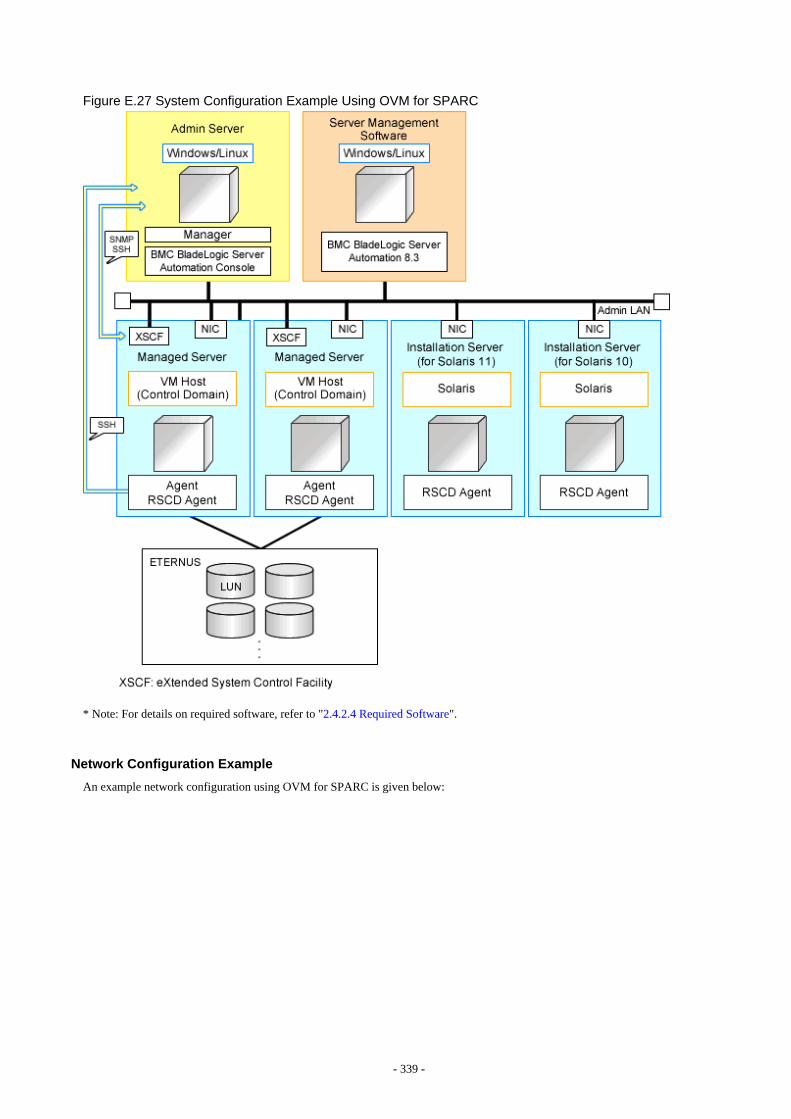
Figure E.27 System Configuration Example Using OVM for SPARC
* Note: For details on required software, refer to "2.4.2.4 Required Software".
Network Configuration Example
An example network configuration using OVM for SPARC is given below:
- 339 -

Figure E.28 Virtual Switch Settings Using Network Resources
L-Server Creation Procedure
The procedure for creating L-Servers is shown below.
- 340 -
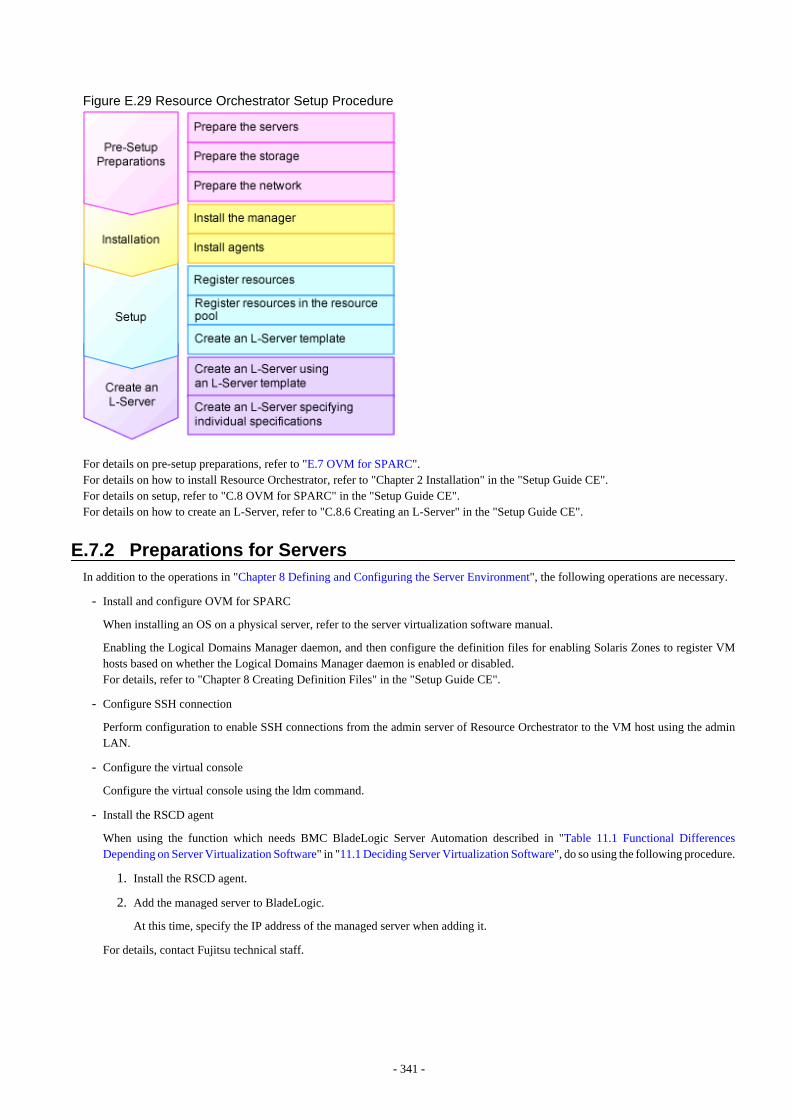
Figure E.29 Resource Orchestrator Setup Procedure
For details on pre-setup preparations, refer to "E.7 OVM for SPARC".For details on how to install Resource Orchestrator, refer to "Chapter 2 Installation" in the "Setup Guide CE".For details on setup, refer to "C.8 OVM for SPARC" in the "Setup Guide CE".For details on how to create an L-Server, refer to "C.8.6 Creating an L-Server" in the "Setup Guide CE".
E.7.2 Preparations for ServersIn addition to the operations in "Chapter 8 Defining and Configuring the Server Environment", the following operations are necessary.
- Install and configure OVM for SPARC
When installing an OS on a physical server, refer to the server virtualization software manual.
Enabling the Logical Domains Manager daemon, and then configure the definition files for enabling Solaris Zones to register VMhosts based on whether the Logical Domains Manager daemon is enabled or disabled.For details, refer to "Chapter 8 Creating Definition Files" in the "Setup Guide CE".
- Configure SSH connection
Perform configuration to enable SSH connections from the admin server of Resource Orchestrator to the VM host using the adminLAN.
- Configure the virtual console
Configure the virtual console using the ldm command.
- Install the RSCD agent
When using the function which needs BMC BladeLogic Server Automation described in "Table 11.1 Functional DifferencesDepending on Server Virtualization Software" in "11.1 Deciding Server Virtualization Software", do so using the following procedure.
1. Install the RSCD agent.
2. Add the managed server to BladeLogic.
At this time, specify the IP address of the managed server when adding it.
For details, contact Fujitsu technical staff.
- 341 -
- Pre-configuration of Server Management Software
When coordinating with BMC BladeLogic Server Automation, register BMC BladeLogic Server Automation in Resource Orchestratoras server management software. Perform pre-configuration before registration.For details on pre-configuration, refer to "I.1 Coordination with BMC BladeLogic Server Automation" in the "Setup Guide CE".
- Preparation for creating an L-Server with an image specified
- When creating an L-Server with a Solaris 10 image specified
When creating an L-Server with a Solaris 10 image specified, coordinate Resource Orchestrator with BMC BladeLogic ServerAutomation, and install the OS using the JumpStart function of Solaris.Therefore, the following setup is necessary.
1. Enable the provisioning function of Application Server of BMC BladeLogic Server Automation.
2. Create a JumpStart server.
For details, refer to the manual of Solaris.
Supported configuration of the JumpStart server
"Installation method"Resource Orchestrator only supports installation via a Local Area Network.Resource Orchestrator does not support the following installation styles.- Installation via a Wide Area Network- Installation from media
"Boot method"Resource Orchestrator only supports a boot server (A system which acquires network information by RARP).Resource Orchestrator does not support booting by a DHCP server.
Configuration contents of the JumpStart server
The settings related to clients are not required. For details, refer to the manual of Solaris.
3. Store the file required for coordination with BMC BladeLogic Server Automation in the JumpStart server.
For details, contact Fujitsu technical staff.
Store the following files in the JumpStart server.
- rscd.sh (*1)
- bmisolaris.tar (*1)
- nsh-install-defaults (*2)
- check file (*3)
*1 It is a file included in BladeLogic Server Automation.*2 Create the response file required for RSCD agent installation, and store it in the JumpStart server.*3 Copy from the installation media of the OS. For details on the copy source, refer to the Solaris manual.
4. Install an RSCD agent in the installation server.
5. Add the installation server to BladeLogic.
6. Configure the datastore of BMC BladeLogic Server Automation.
Create a datastore instance of "Jumpstart DataStore".
7. Configure the system package type of BMC BladeLogic Server Automation.
Configure the system package type of "Solaris 10 Sparc".
- When creating an L-Server with a Solaris 11 image specified
When creating an L-Server with a Solaris 11 image specified, coordinate Resource Orchestrator with BMC BladeLogic ServerAutomation, and install the OS using the Automated Installation (hereinafter AI) function of Solaris.Therefore, the following setup is necessary.
1. Enable the provisioning function of Application Server of BMC BladeLogic Server Automation.
- 342 -
2. Create an Automated Installation server.
For details, refer to the manual of Solaris.
Supported configuration of the Automated Installation server
Create the Automated Installation service, without setting up DHCP.
Configuration contents of the Automated Installation server
The settings related to clients are not required. For details, refer to the manual of Solaris.Creation of an IPS repository server for the OS is also necessary.Create an Automated Installation service using the following name.
ROR_AI
3. Store the file required for coordination with BMC BladeLogic Server Automation in the Automated Installation server.
For details, contact Fujitsu technical staff.
Store the following files in the Automated Installation server.
- rscd.sh (*1)
- bmisolaris.tar (*1)
- nsh-install-defaults (*2)
*1 It is a file included in BladeLogic Server Automation.*2 Create the response file required for RSCD agent installation, and store in the Automated Installation server.
4. Install an RSCD agent in the installation server.
5. Add the installation server to BladeLogic.
6. Configure the datastore of BMC BladeLogic Server Automation.
Create a datastore instance of "AI DataStore".
7. Configure the system package type of BMC BladeLogic Server Automation.
Configure the system package type of "Solaris 11 Sparc".
E.7.3 Storage PreparationsThis section explains the preparations for setting up storage.
Supported Storage Configurations
The supported storage configurations are as follow:
- Storage supported by OVM for SPARC
For details on the storage supported by OVM for SPARC, refer to the OVM for SPARC manual.
Preparations for Storage Environments
Check the following:
- After installing and configuring OVM for SPARC, configure the virtual disk services and register the disks.
- The storage affinity switchover method can be used as a server switchover function.
For details on how to configure the server switchover, refer to "8.1.6 Settings when Switching Over Fujitsu M10/SPARC EnterpriseServers".
For details on server switchover, refer to "Chapter 4 Server Switchover" in the "Operation Guide VE".
- When using the server switchover function, design the area used for each domain so that it can be referred to in the same way bothbefore and after switchover.
For server switchover, use an area that can be referred to for the access path that is the target of switchover.
- 343 -
- When using the server switchover function, guest domains are not automatically started.
Perform configuration so that guest domains are automatically started when control domains are started after server switchover.
E.7.4 Network PreparationsCheck the following:
- The configuration for the admin and public LANs has been designed
- The network environment for the admin LAN is configured
- The VLAN ID to allocate to the network resource has been configured
- The virtual switch has been configured beforehand
When Using IBP
When using virtual L-Servers, connect the IBP uplink sets used for the public LAN and admin LAN to the VM host regardless of VIOM,after creating each IBP uplink set. It is not necessary to use the same name for the uplink set and the name of the network resource.
Virtual switch creation
It is necessary to create the virtual switch in OVM for SPARC, in order to connect the L-Server to the network.For details on how to create a virtual switch, refer to the OVM for SPARC manual.
E.8 Citrix XenServerThis section explains how to configure Citrix XenServer as server virtualization software.
E.8.1 System ConfigurationThis section explains a system configuration.
Example of System Configuration
System configuration examples are given below.
- 344 -
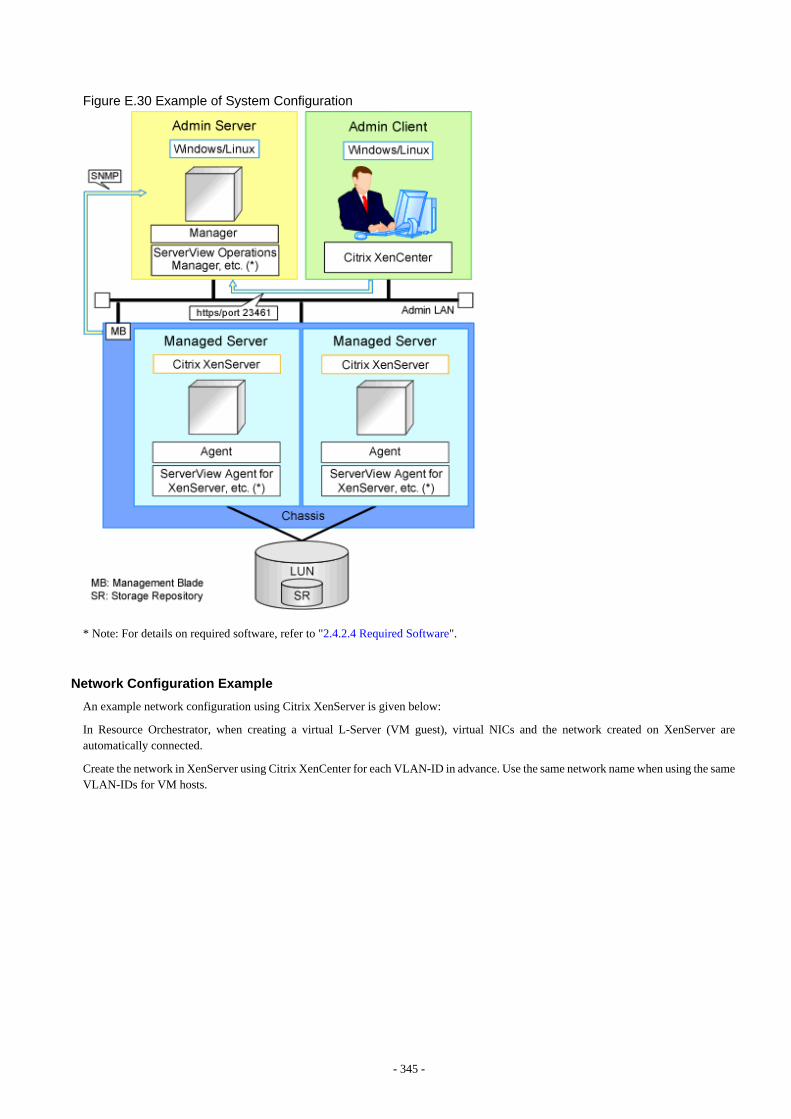
Figure E.30 Example of System Configuration
* Note: For details on required software, refer to "2.4.2.4 Required Software".
Network Configuration Example
An example network configuration using Citrix XenServer is given below:
In Resource Orchestrator, when creating a virtual L-Server (VM guest), virtual NICs and the network created on XenServer areautomatically connected.
Create the network in XenServer using Citrix XenCenter for each VLAN-ID in advance. Use the same network name when using the sameVLAN-IDs for VM hosts.
- 345 -

Figure E.31 Network Configuration Example
L-Server Creation Procedure
Use the following procedure to create L-Servers:
- 346 -
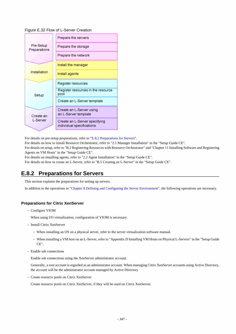
Figure E.32 Flow of L-Server Creation
For details on pre-setup preparations, refer to "E.8.2 Preparations for Servers".For details on how to install Resource Orchestrator, refer to "2.1 Manager Installation" in the "Setup Guide CE".For details on setup, refer to "B.2 Registering Resources with Resource Orchestrator" and "Chapter 11 Installing Software and RegisteringAgents on VM Hosts" in the "Setup Guide CE".For details on installing agents, refer to "2.2 Agent Installation" in the "Setup Guide CE".For details on how to create an L-Server, refer to "B.5 Creating an L-Server" in the "Setup Guide CE".
E.8.2 Preparations for ServersThis section explains the preparations for setting up servers.
In addition to the operations in "Chapter 8 Defining and Configuring the Server Environment", the following operations are necessary.
Preparations for Citrix XenServer
- Configure VIOM
When using I/O virtualization, configuration of VIOM is necessary.
- Install Citrix XenServer
- When installing an OS on a physical server, refer to the server virtualization software manual.
- When installing a VM host on an L-Server, refer to "Appendix D Installing VM Hosts on Physical L-Servers" in the "Setup GuideCE".
- Enable ssh connections
Enable ssh connections using the XenServer administrator account.
Generally, a root account is regarded as an administrator account. When managing Citrix XenServer accounts using Active Directory,the account will be the administrator account managed by Active Directory
- Create resource pools on Citrix XenServer
Create resource pools on Citrix XenServer, if they will be used on Citrix XenServer.
- 347 -
E.8.3 Preparations for StorageThis section explains the preparations for setting up storage.
Supported Storage Configurations
The supported storage configurations are as follow:
- Remote access storage (one of iSCSI, NFS, or HBA) supported by Citrix XenServerFor details on the storage supported by Citrix XenServer, refer to the Citrix XenServer manual.
- Check in advance that the storage repository to use is shared with all VM hosts in the Citrix XenServer pool.
Effective Utilization of Storage Using Thin Provisioning
In this manual, for the disks of Citrix XenServer, sparse allocation is regarded as Thin Provisioning, and non-sparse allocation is regardedas Thick Provisioning.
Thin provisioning is technology for virtualizing storage capacities.
It enables efficient utilization of storage.
The function does not require the necessary storage capacity to be secured in advance, and can secure and extend the storage capacityaccording to how much is actually being used.
Citrix XenServer can realize Thin Provisioning using an NFS storage repository.
In Resource Orchestrator, configure Thin Provisioning as follows:
- When registering an NFS storage repository as a virtual storage resource registered in a storage pool with Thin Provisioning attributesset, set the thin format and allocate the disk resources to an L-Server.
For how to set thin provisioning attributes for a storage pool, refer to "20.2 Creating" in the "User's Guide for Infrastructure Administrators(Resource Management) CE".
For details on the display of available free space of storage pools and the calculation method for free space, refer to "20.6 Viewing" in the"User's Guide for Infrastructure Administrators (Resource Management) CE".
Note
- When registering a NFS storage repository as a virtual storage resource in a storage pool without Thin Provisioning attributes set, ascalculation is performed assuming that the necessary amount of space has been allocated, the amount of available space is less thanthe actual free space.
- When registering a storage repository other than NFS as a virtual storage resource registered in a storage pool with Thin Provisioningattributes set, secure the necessary space, and allocate the disk resources to an L-Server.
Allocating Storage to a Virtual L-Server
1. When a VM host is registered as storage management software, the storage repositories made beforehand are detected automaticallyas a virtual storage resource.
2. From the detected virtual storage resources, virtual storage resources meeting virtual L-Server specifications are automaticallyselected by Resource Orchestrator.
(Virtual storage resources registered in a storage pool where the priority level is high and virtual storage resources with a highcapacity are selected by priority.)
3. From the automatically selected virtual storage resources, disk resources (such as virtual disks) of the specified size are automaticallycreated and allocated to the virtual L-Server.
- 348 -
Information
The storage repository name is used for the virtual storage resource name.
- However, when characters other than the following are included in a datastore name, they are replaced with hyphens ("-").
- Numerals (0 to 9)
- Alphabetical characters: upper case (A to Z), lower case (a to z)
- Hyphens ("-") and underscores ("_")
- When a multi-byte character is contained in the name of storage repository, it is not detected.
- When this product manages two or more types of storage management software, there may be multiple storage repositories with thesame name. In that case, the form of virtual storage resource names is the datastore name + "_" + serial number (Example: "_1").
E.8.4 Network PreparationsThis section explains the preparations for setting up a network.
Defining and Configuring the Network Environment
For details, refer to "Chapter 9 Defining and Configuring the Network Environment".
Regarding the descriptions for each server virtualization software in the reference, Citrix XenServer is the same as RHEL5-Xen, RHEL-KVM, and OVM for x86.
Network Preparations
Check the following:
- The configuration for the admin and public LANs has been designed
- The network environment for the admin LAN is configured
- The VLAN ID to allocate to the network resource has been configured
- The virtual machine network has been configured
Create a Network on XenServer
It is necessary to create the network in XenServer, in order to connect the L-Server to the network. For details on how to create a network,refer to the Citrix XenServer manual.
E.9 OVM for x86 3.2This section explains how to configure OVM for x86 3.2 as server virtualization software.
E.9.1 System ConfigurationThis section explains a system configuration.
Example of System Configuration
System configuration examples are given below.
- 349 -
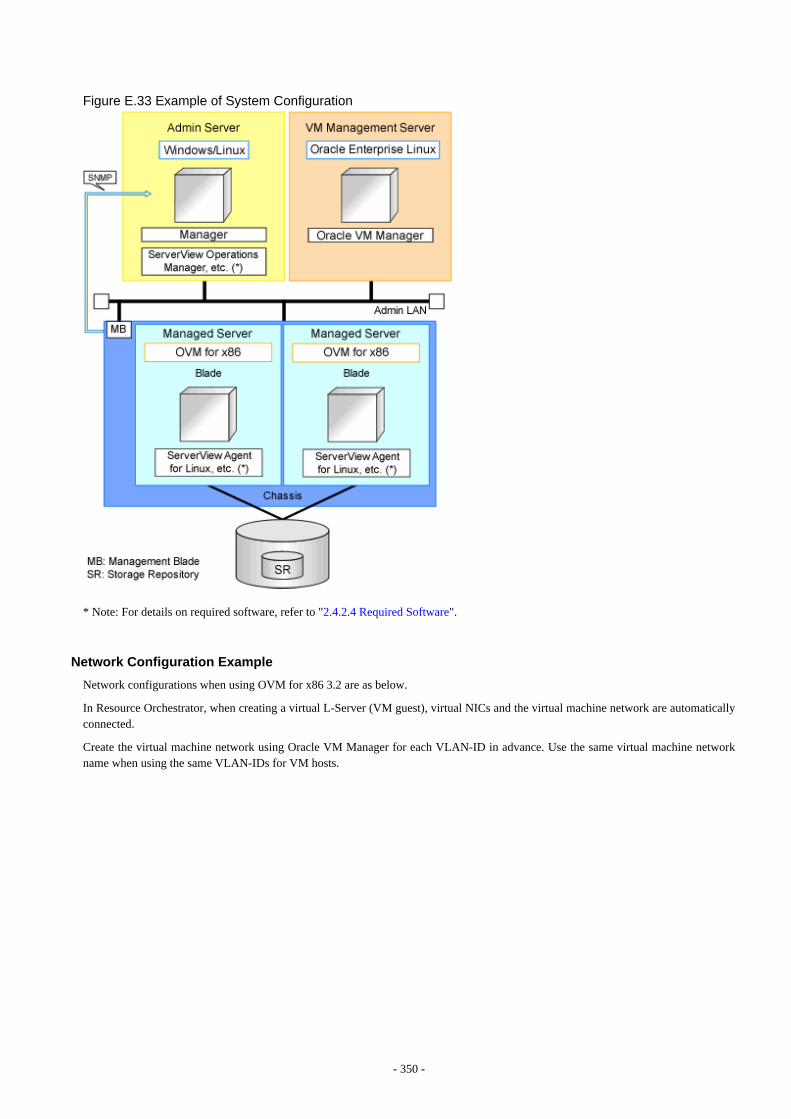
Figure E.33 Example of System Configuration
* Note: For details on required software, refer to "2.4.2.4 Required Software".
Network Configuration Example
Network configurations when using OVM for x86 3.2 are as below.
In Resource Orchestrator, when creating a virtual L-Server (VM guest), virtual NICs and the virtual machine network are automaticallyconnected.
Create the virtual machine network using Oracle VM Manager for each VLAN-ID in advance. Use the same virtual machine networkname when using the same VLAN-IDs for VM hosts.
- 350 -
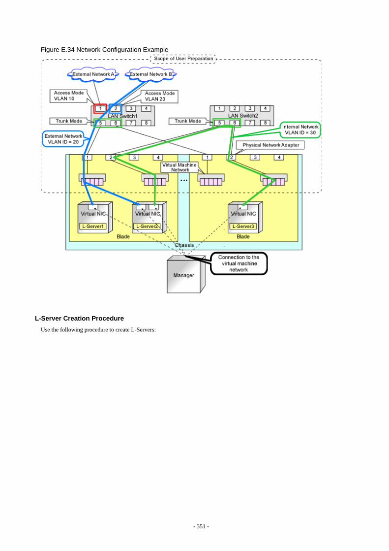
Figure E.34 Network Configuration Example
L-Server Creation Procedure
Use the following procedure to create L-Servers:
- 351 -

Figure E.35 Flow of L-Server Creation
For details on pre-setup preparations, refer to "E.9.2 Preparations for Servers".For details on how to install Resource Orchestrator, refer to "2.1 Manager Installation" in the "Setup Guide CE".For details on setup, refer to "B.2 Registering Resources with Resource Orchestrator" and "Chapter 11 Installing Software and RegisteringAgents on VM Hosts" in the "Setup Guide CE".
For details on installing agents, refer to "2.2 Agent Installation" in the "Setup Guide CE".For details on how to create an L-Server, refer to "B.5 Creating an L-Server" in the "Setup Guide CE".
E.9.2 Preparations for ServersThis section explains the preparations for setting up servers.
In addition to the operations in "Chapter 8 Defining and Configuring the Server Environment", the following operations are necessary.
Preparations for OVM for x86 3.2
- Install and configure Oracle VM Manager
Necessary for management of VM hosts and L-Servers.
After installing Oracle VM Manager, create a server pool, and register resources.
When installing a VM host on an L-Server, refer to "Appendix D Installing VM Hosts on Physical L-Servers" in the "Setup GuideCE".
- Enable ssh connections
For Oracle VM Server for x86, configure the settings using a root account so ssh connections are available.
- Register a virtual NIC in Oracle VM Manager
Register virtual NICs in Oracle VM Manager.
In this procedure, register the number calculated using the formula: number of L-Servers to be created * 8(*1) + 30(*2) * 31(*3)
*1: 8 is the maximum number of NICs which can be connected to an L-Server*2: The maximum number of L-Servers that can be created simultaneously using ROR*3: 31 is the maximum number of NICs which can be connected to a template as Oracle VM
- 352 -
E.9.3 Preparations for StorageThis section explains the preparations for setting up storage.
Supported Storage Configurations
The supported storage configurations are as follow:
- Storage supported by OVM for x86 3.2
For details on the storage supported by OVM for x86 3.2, refer to the Oracle VM manual.
Effective Utilization of Storage Using Thin Provisioning
In this manual, for the disks of Oracle VM Manager, sparse allocation is regarded as Thin Provisioning, and non-sparse allocation isregarded as Thick Provisioning.
Thin provisioning is technology for virtualizing storage capacities.
It enables efficient utilization of storage.
The function does not require the necessary storage capacity to be secured in advance, and can secure and extend the storage capacityaccording to how much is actually being used.
In Resource Orchestrator, virtual storage resources can be managed in storage pools.
Storage pools must take into account the existence of thin provisioning attributes.
The following resources can be registered in a storage pool with thin provisioning attributes set:
- Virtual storage resources with thin provisioning attributes set
The following resources can be registered in a storage pool without thin provisioning attributes set:
- Virtual storage resources with thick provisioning attributes set
Thin Provisioning cannot be configured in an OVM for x86 3.2 storage repository. Therefore, in Resource Orchestrator, the attributesconfigured in the registered storage pool are regarded as the provisioning attributes of the storage repository.
For details on the provisioning attributes of disk resources allocated to an L-Server during creation, refer to "B.3 Registering Resourcesin Resource Pools" in the "Setup Guide CE".
For how to set thin provisioning attributes for a storage pool, refer to "20.2 Creating" in the "User's Guide for Infrastructure Administrators(Resource Management) CE".
Allocating Storage to a Virtual L-Server
Refer to the "Allocate disk resources (virtual disks) automatically created from virtual storage resources (datastores)" section in "AllocatingStorage to a Virtual L-Server" in "10.1.1 Allocating Storage".
Preparations for Storage Environments
Refer to "D.3.2 Preparations for Storage Environments" in "D.3 Storage Preparations".
E.9.4 Preparations for the Network EnvironmentThis section explains the preparations for setting up a network.
- 353 -
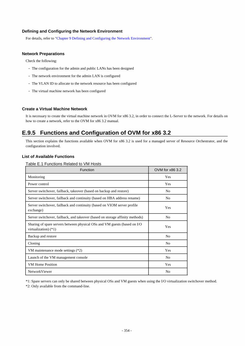
Defining and Configuring the Network Environment
For details, refer to "Chapter 9 Defining and Configuring the Network Environment".
Network Preparations
Check the following:
- The configuration for the admin and public LANs has been designed
- The network environment for the admin LAN is configured
- The VLAN ID to allocate to the network resource has been configured
- The virtual machine network has been configured
Create a Virtual Machine Network
It is necessary to create the virtual machine network in OVM for x86 3.2, in order to connect the L-Server to the network. For details onhow to create a network, refer to the OVM for x86 3.2 manual.
E.9.5 Functions and Configuration of OVM for x86 3.2This section explains the functions available when OVM for x86 3.2 is used for a managed server of Resource Orchestrator, and theconfiguration involved.
List of Available Functions
Table E.1 Functions Related to VM Hosts
Function OVM for x86 3.2
Monitoring Yes
Power control Yes
Server switchover, failback, takeover (based on backup and restore) No
Server switchover, failback and continuity (based on HBA address rename) No
Server switchover, failback and continuity (based on VIOM server profileexchange)
Yes
Server switchover, failback, and takeover (based on storage affinity methods) No
Sharing of spare servers between physical OSs and VM guests (based on I/Ovirtualization) (*1)
Yes
Backup and restore No
Cloning No
VM maintenance mode settings (*2) Yes
Launch of the VM management console No
VM Home Position Yes
NetworkViewer No
*1: Spare servers can only be shared between physical OSs and VM guests when using the I/O virtualization switchover method.*2: Only available from the command-line.
- 354 -
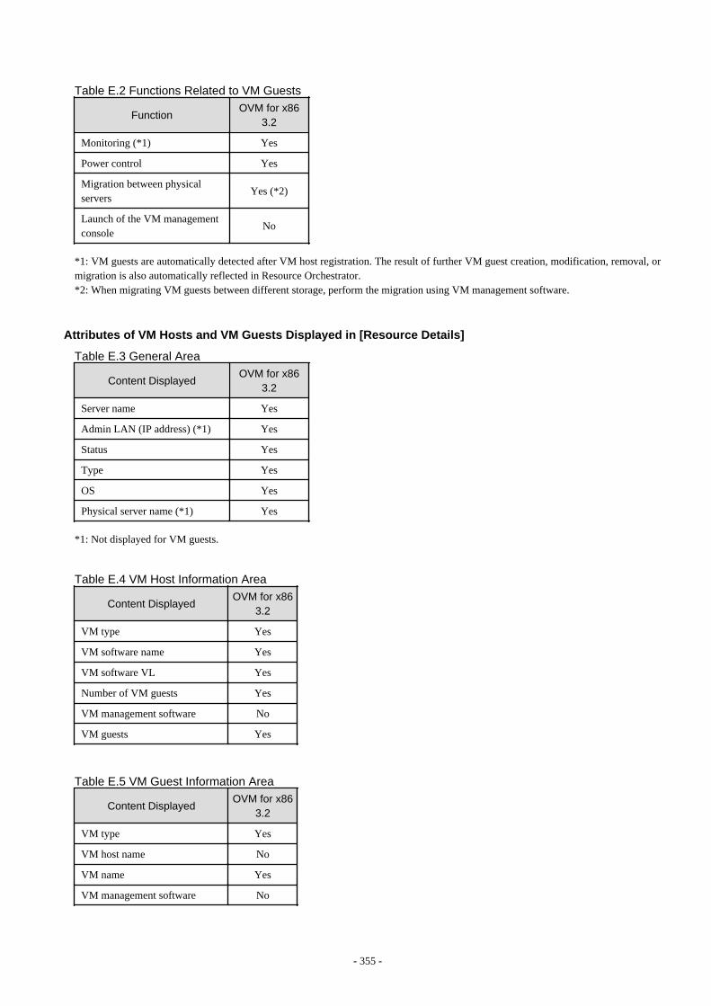
Table E.2 Functions Related to VM Guests
FunctionOVM for x86
3.2
Monitoring (*1) Yes
Power control Yes
Migration between physicalservers
Yes (*2)
Launch of the VM managementconsole
No
*1: VM guests are automatically detected after VM host registration. The result of further VM guest creation, modification, removal, ormigration is also automatically reflected in Resource Orchestrator.*2: When migrating VM guests between different storage, perform the migration using VM management software.
Attributes of VM Hosts and VM Guests Displayed in [Resource Details]
Table E.3 General Area
Content DisplayedOVM for x86
3.2
Server name Yes
Admin LAN (IP address) (*1) Yes
Status Yes
Type Yes
OS Yes
Physical server name (*1) Yes
*1: Not displayed for VM guests.
Table E.4 VM Host Information Area
Content DisplayedOVM for x86
3.2
VM type Yes
VM software name Yes
VM software VL Yes
Number of VM guests Yes
VM management software No
VM guests Yes
Table E.5 VM Guest Information Area
Content DisplayedOVM for x86
3.2
VM type Yes
VM host name No
VM name Yes
VM management software No
- 355 -
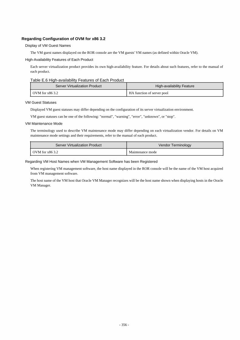
Regarding Configuration of OVM for x86 3.2
Display of VM Guest Names
The VM guest names displayed on the ROR console are the VM guests' VM names (as defined within Oracle VM).
High-Availability Features of Each Product
Each server virtualization product provides its own high-availability feature. For details about such features, refer to the manual ofeach product.
Table E.6 High-availability Features of Each Product
Server Virtualization Product High-availability Feature
OVM for x86 3.2 HA function of server pool
VM Guest Statuses
Displayed VM guest statuses may differ depending on the configuration of its server virtualization environment.
VM guest statuses can be one of the following: "normal", "warning", "error", "unknown", or "stop".
VM Maintenance Mode
The terminology used to describe VM maintenance mode may differ depending on each virtualization vendor. For details on VMmaintenance mode settings and their requirements, refer to the manual of each product.
Server Virtualization Product Vendor Terminology
OVM for x86 3.2 Maintenance mode
Regarding VM Host Names when VM Management Software has been Registered
When registering VM management software, the host name displayed in the ROR console will be the name of the VM host acquiredfrom VM management software.
The host name of the VM host that Oracle VM Manager recognizes will be the host name shown when displaying hosts in the OracleVM Manager.
- 356 -
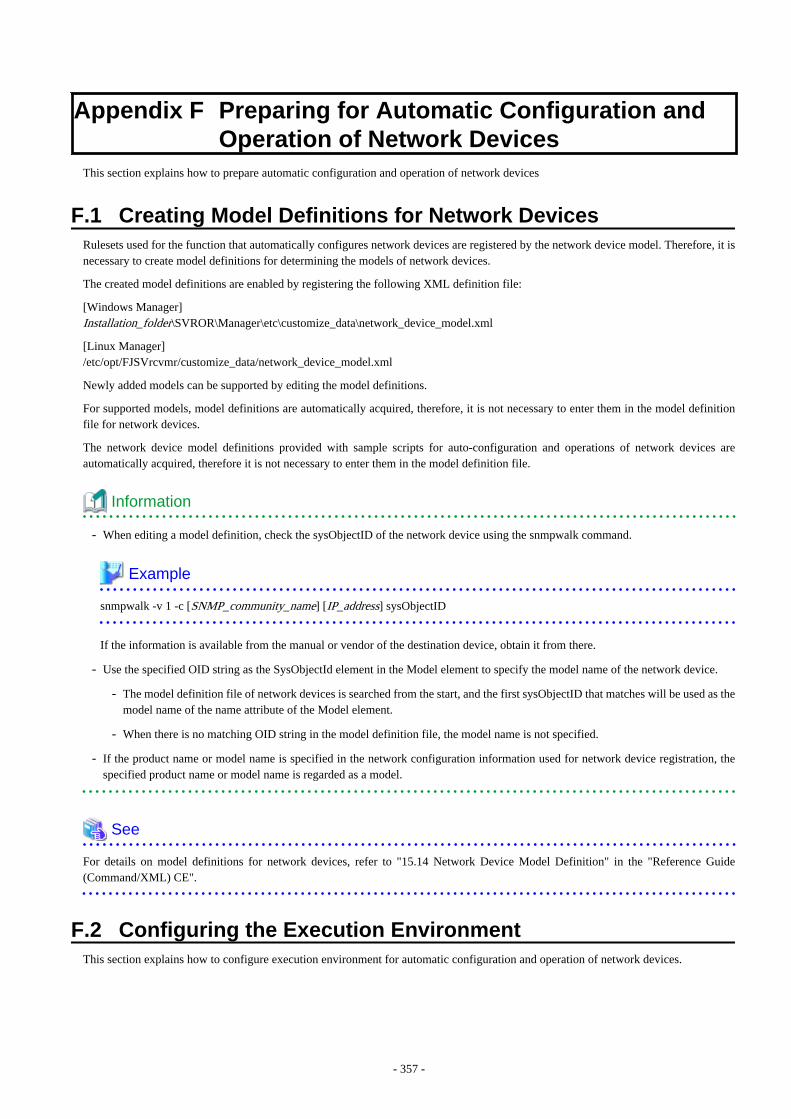
Appendix F Preparing for Automatic Configuration andOperation of Network Devices
This section explains how to prepare automatic configuration and operation of network devices
F.1 Creating Model Definitions for Network DevicesRulesets used for the function that automatically configures network devices are registered by the network device model. Therefore, it isnecessary to create model definitions for determining the models of network devices.
The created model definitions are enabled by registering the following XML definition file:
[Windows Manager]Installation_folder\SVROR\Manager\etc\customize_data\network_device_model.xml
[Linux Manager]/etc/opt/FJSVrcvmr/customize_data/network_device_model.xml
Newly added models can be supported by editing the model definitions.
For supported models, model definitions are automatically acquired, therefore, it is not necessary to enter them in the model definitionfile for network devices.
The network device model definitions provided with sample scripts for auto-configuration and operations of network devices areautomatically acquired, therefore it is not necessary to enter them in the model definition file.
Information
- When editing a model definition, check the sysObjectID of the network device using the snmpwalk command.
Example
snmpwalk -v 1 -c [SNMP_community_name] [IP_address] sysObjectID
If the information is available from the manual or vendor of the destination device, obtain it from there.
- Use the specified OID string as the SysObjectId element in the Model element to specify the model name of the network device.
- The model definition file of network devices is searched from the start, and the first sysObjectID that matches will be used as themodel name of the name attribute of the Model element.
- When there is no matching OID string in the model definition file, the model name is not specified.
- If the product name or model name is specified in the network configuration information used for network device registration, thespecified product name or model name is regarded as a model.
See
For details on model definitions for network devices, refer to "15.14 Network Device Model Definition" in the "Reference Guide(Command/XML) CE".
F.2 Configuring the Execution EnvironmentThis section explains how to configure execution environment for automatic configuration and operation of network devices.
- 357 -
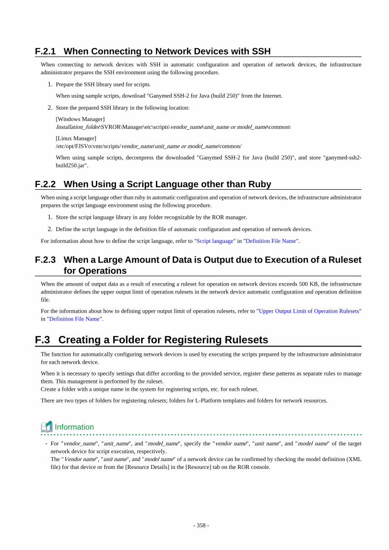
F.2.1 When Connecting to Network Devices with SSHWhen connecting to network devices with SSH in automatic configuration and operation of network devices, the infrastructureadministrator prepares the SSH environment using the following procedure.
1. Prepare the SSH library used for scripts.
When using sample scripts, download "Ganymed SSH-2 for Java (build 250)" from the Internet.
2. Store the prepared SSH library in the following location:
[Windows Manager]Installation_folder\SVROR\Manager\etc\scripts\vendor_name\unit_name or model_name\common\
[Linux Manager]/etc/opt/FJSVrcvmr/scripts/vendor_name/unit_name or model_name/common/
When using sample scripts, decompress the downloaded "Ganymed SSH-2 for Java (build 250)", and store "ganymed-ssh2-build250.jar".
F.2.2 When Using a Script Language other than RubyWhen using a script language other than ruby in automatic configuration and operation of network devices, the infrastructure administratorprepares the script language environment using the following procedure.
1. Store the script language library in any folder recognizable by the ROR manager.
2. Define the script language in the definition file of automatic configuration and operation of network devices.
For information about how to define the script language, refer to "Script language" in "Definition File Name".
F.2.3 When a Large Amount of Data is Output due to Execution of a Rulesetfor Operations
When the amount of output data as a result of executing a ruleset for operation on network devices exceeds 500 KB, the infrastructureadministrator defines the upper output limit of operation rulesets in the network device automatic configuration and operation definitionfile.
For the information about how to defining upper output limit of operation rulesets, refer to "Upper Output Limit of Operation Rulesets"in "Definition File Name".
F.3 Creating a Folder for Registering RulesetsThe function for automatically configuring network devices is used by executing the scripts prepared by the infrastructure administratorfor each network device.
When it is necessary to specify settings that differ according to the provided service, register these patterns as separate rules to managethem. This management is performed by the ruleset.Create a folder with a unique name in the system for registering scripts, etc. for each ruleset.
There are two types of folders for registering rulesets; folders for L-Platform templates and folders for network resources.
Information
- For "vendor_name", "unit_name", and "model_name", specify the "vendor name", "unit name", and "model name" of the targetnetwork device for script execution, respectively.The "Vendor name", "unit name", and "model name" of a network device can be confirmed by checking the model definition (XMLfile) for that device or from the [Resource Details] in the [Resource] tab on the ROR console.
- 358 -
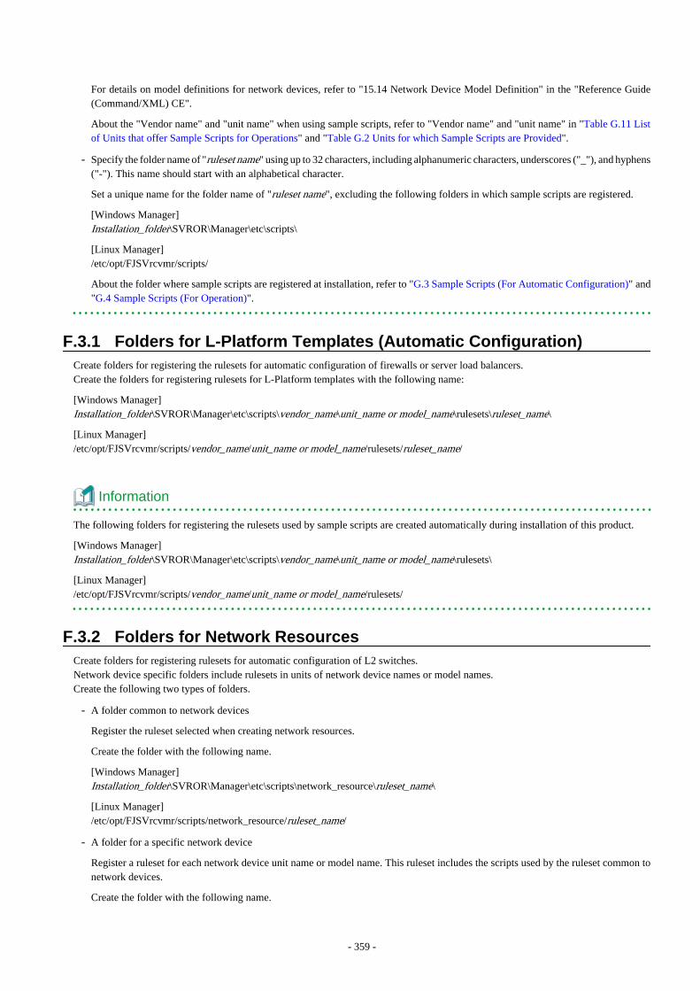
For details on model definitions for network devices, refer to "15.14 Network Device Model Definition" in the "Reference Guide(Command/XML) CE".
About the "Vendor name" and "unit name" when using sample scripts, refer to "Vendor name" and "unit name" in "Table G.11 Listof Units that offer Sample Scripts for Operations" and "Table G.2 Units for which Sample Scripts are Provided".
- Specify the folder name of "ruleset name" using up to 32 characters, including alphanumeric characters, underscores ("_"), and hyphens("-"). This name should start with an alphabetical character.
Set a unique name for the folder name of "ruleset name", excluding the following folders in which sample scripts are registered.
[Windows Manager]Installation_folder\SVROR\Manager\etc\scripts\
[Linux Manager]/etc/opt/FJSVrcvmr/scripts/
About the folder where sample scripts are registered at installation, refer to "G.3 Sample Scripts (For Automatic Configuration)" and"G.4 Sample Scripts (For Operation)".
F.3.1 Folders for L-Platform Templates (Automatic Configuration)Create folders for registering the rulesets for automatic configuration of firewalls or server load balancers.Create the folders for registering rulesets for L-Platform templates with the following name:
[Windows Manager]Installation_folder\SVROR\Manager\etc\scripts\vendor_name\unit_name or model_name\rulesets\ruleset_name\
[Linux Manager]/etc/opt/FJSVrcvmr/scripts/vendor_name/unit_name or model_name/rulesets/ruleset_name/
Information
The following folders for registering the rulesets used by sample scripts are created automatically during installation of this product.
[Windows Manager]Installation_folder\SVROR\Manager\etc\scripts\vendor_name\unit_name or model_name\rulesets\
[Linux Manager]/etc/opt/FJSVrcvmr/scripts/vendor_name/unit_name or model_name/rulesets/
F.3.2 Folders for Network ResourcesCreate folders for registering rulesets for automatic configuration of L2 switches.Network device specific folders include rulesets in units of network device names or model names.Create the following two types of folders.
- A folder common to network devices
Register the ruleset selected when creating network resources.
Create the folder with the following name.
[Windows Manager]Installation_folder\SVROR\Manager\etc\scripts\network_resource\ruleset_name\
[Linux Manager]/etc/opt/FJSVrcvmr/scripts/network_resource/ruleset_name/
- A folder for a specific network device
Register a ruleset for each network device unit name or model name. This ruleset includes the scripts used by the ruleset common tonetwork devices.
Create the folder with the following name.
- 359 -
[Windows Manager]Installation_folder\SVROR\Manager\etc\scripts\vendor_name\unit_name or model_name\rulesets\ruleset_name\
[Linux Manager]/etc/opt/FJSVrcvmr/scripts/vendor_name/unit_name or model_name/rulesets/ruleset_name/
Information
- The following folders for registering the rulesets used by sample scripts are created automatically during installation of this product.
- A folder common to network devices
[Windows Manager]Installation_folder \SVROR\Manager\etc\scripts\network_resource\
[Linux Manager]/etc/opt/FJSVrcvmr/scripts/network_resource/
- A folder for a specific network device
[Windows Manager]Installation_folder\SVROR\Manager\etc\scripts\vendor_name\unit_name or model_name\rulesets\
[Linux Manager]/etc/opt/FJSVrcvmr/scripts/vendor_name/unit_name or model_name/rulesets/
- When configuring a tagged vlan in a SR-X300 using the sample script, register the following rulesets in the folder for registeringrulesets for network resources.
- Rulesets registered in the folder for a particular network device
- tag_vlan_port--SR-X300 or
- tag_vlan_port--SR-X300_n
- Rulesets registered in the folder common to network devices
- tag_vlan_net--SR-X300 or
- tag_vlan_net--SR-X300_n
Regarding combinations of rulesets of sample scripts, refer to "G.3.12 For Deploying L2 Switches".
F.3.3 Common Information of RulesetsIt is possible to share the information used for ensuring consistency of configurations between multiple rulesets for automatic configurationof the same device type. For example, there is an information file to common information for identifying definitions.The infrastructure administrator should create the following system directory and place the files in it:
[Windows Manager]Installation_folder\SVROR\Manager\etc\scripts\vendor_name\unit_name or model_name\common\
[Linux Manager]/etc/opt/FJSVrcvmr/scripts/vendor_name/unit_name or model_name/common/
Information
The folders for registering the rulesets used for the sample scripts are created automatically during installation of this product.
- 360 -
F.3.4 Folders for L-Platform Templates (Operations)Create folders for registering rulesets for operation of server load balancers.Create the folders for registering rulesets for L-Platform templates with the following name:
[Windows Manager]Installation_folder\SVROR\Manager\etc\scripts\vendor_name\unit_name or model_name\operations\ruleset_name\
[Linux Manager]/etc/opt/FJSVrcvmr/scripts/vendor_name/unit_name or model_name/operations/ruleset_name/
Information
The following folders for registering the rulesets used by sample scripts are created automatically during installation of this product.
[Windows Manager]Installation_folder\SVROR\Manager\etc\scripts\vendor_name\unit_name or model_name \operations\
[Linux Manager]/etc/opt/FJSVrcvmr/scripts/vendor_name/unit_name or model_name /operations/
F.4 Basic Script StructureThis section explains the basic operation and structure of a script used for automatic configuration and operation of network devices.
The basic flow of configuration and operation of network devices using scripts is as follows:
1. Confirm the syntax of the script list file.
2. The following is processed starting from the start of the script list file.
a. Specify the target network device.
b. Complete the script file to convert variable information in the script file corresponding to "Script Name" with the informationof the parameter file.
c. When "cmd operand" is specified in a script list, complete the specified command file. In this process, variable informationin the command file is converted using the information of parameter files.
d. Script files are executed sequentially, from top to bottom.At this time, if necessary, commands are loaded from the command file.
For the function of each file, refer to "F.4.1 Function and Attributes of Each File".
As examples of basic script structure, the following basic structures are shown.
- Basic Structure Example when Using Scripts for L-Platform Templates (Automatic Configuration)
- Basic Structure for Network Resources
- Basic Structure of an L-Platform Template (Operation)
- 361 -
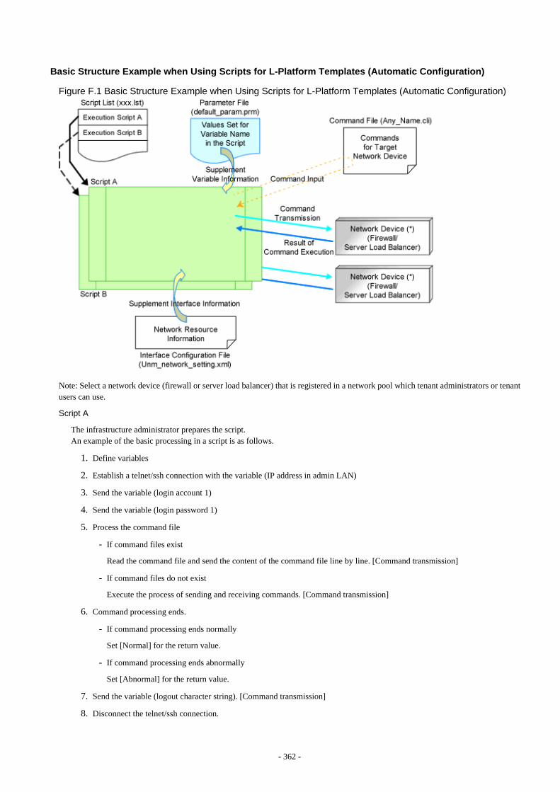
Basic Structure Example when Using Scripts for L-Platform Templates (Automatic Configuration)
Figure F.1 Basic Structure Example when Using Scripts for L-Platform Templates (Automatic Configuration)
Note: Select a network device (firewall or server load balancer) that is registered in a network pool which tenant administrators or tenantusers can use.
Script A
The infrastructure administrator prepares the script.An example of the basic processing in a script is as follows.
1. Define variables
2. Establish a telnet/ssh connection with the variable (IP address in admin LAN)
3. Send the variable (login account 1)
4. Send the variable (login password 1)
5. Process the command file
- If command files exist
Read the command file and send the content of the command file line by line. [Command transmission]
- If command files do not exist
Execute the process of sending and receiving commands. [Command transmission]
6. Command processing ends.
- If command processing ends normally
Set [Normal] for the return value.
- If command processing ends abnormally
Set [Abnormal] for the return value.
7. Send the variable (logout character string). [Command transmission]
8. Disconnect the telnet/ssh connection.
- 362 -

Script B
The infrastructure administrator prepares the script.The example of the basic processing in the script is the same as for script A.
Script List (xxx.lst)
The infrastructure administrator prepares the script.The script list of the ruleset selected when creating the L-Platform.Scripts specified in script lists are executed sequentially.
Parameter File (default_param.prm)
The infrastructure administrator prepares the script.Information for setting or changing specified parameter values when tenant administrators or users create or modify L-Platforms.
Command File (Any_Name.cli)
The infrastructure administrator prepares the script.Define processes for after log in to devices with log in accounts, excluding command processes included in scripts.
Interface Configuration File (Unm_network_setting.xml)
The infrastructure administrator prepares the script.Prepare one script per system.
Basic Structure for Network Resources
Figure F.2 Basic Structure Example when Using Scripts for Network Resources
Note: It is possible to specify parameters in a script without a parameter file.
Script A
This script is prepared by the infrastructure administrator and registered under a specific network device ruleset folder.An example of the basic process in a script is as follows:
1. Define variables
2. Establish a telnet/ssh connection with the variable (IP address in admin LAN)
3. Send the variable (login account 1)
4. Send the variable (login password 1)
- 363 -

5. Process the command file
- If command files exist
Read the command file and send the content of the command file line by line. [Command transmission]
- If command files do not exist
Execute the process of sending and receiving commands. [Command transmission]
6. Command processing ends.
- If command processing ends normally
Set [Normal] for the return value.
- If command processing ends abnormally
Set [Abnormal] for the return value.
7. Send the variable (logout character string). [Command transmission]
8. Disconnect the telnet/ssh connection.
Script B
This script is prepared by the infrastructure administrator and registered under a specific network device ruleset folder.The example of the basic processing in the script is the same as for script A.
Script List (xxx.lst)
This script is prepared by the infrastructure administrator and registered under a specific network device ruleset folder.For network devices related to the operated L-Platform.Scripts specified in the script list are executed in order.
Parameter File (Any_Name.prm)
The infrastructure administrator prepares this if necessary.
Command File (Any_Name.cli)
The infrastructure administrator prepares the script.Define processes for after log in to devices with log in accounts, excluding command processes included in scripts.
Basic Structure of an L-Platform Template (Operation)
Figure F.3 Basic Structure Example when Using Scripts for L-Platform Templates (Operations)
Note: Select a network device (server load balancer) that is registered in a network pool which the tenant administrators or tenant userscreating the L-Platform can use.
- 364 -
Script A
The infrastructure administrator prepares the script.An example of the basic processing in a script is as follows.
1. Define variables
2. Establish a telnet/ssh connection with the variable (IP address in admin LAN)
3. Send the variable (login account 1)
4. Send the variable (login password 1)
5. Process the command file
- If command files exist
Read the command file and send the content of the command file line by line. [Command transmission]Obtains command execution results and writes them to the standard output
- If command files do not exist
Execute the process of sending and receiving commands. [Command transmission]Obtains command execution results and writes them to the standard output
6. Command processing ends.
- If command processing ends normally
Set [Normal] for the return value.
- If command processing ends abnormally
Set [Abnormal] for the return value.
7. Send the variable (logout character string). [Command transmission]
8. Disconnect the telnet/ssh connection.
Script B
The infrastructure administrator prepares the script.The example of the basic processing in the script is the same as for script A.
Script List (xxx.lst)
The infrastructure administrator prepares the script.Script list of the ruleset selected when creating the L-Platform.Scripts specified in the script list are executed in order.
Parameter File (default_param.prm)
The infrastructure administrator prepares the script.Information for setting specified parameter values when tenant administrators or users operate an L-Platform.
Command File (Any_Name.cli)
The infrastructure administrator prepares the script.Define processes for after log in to devices with log in accounts, excluding command processes included in scripts.
Note that each file needs to be created according to the script to be used.The example of basic structure is the explanation of the structure corresponding to the sample scripts provided with this product.
F.4.1 Function and Attributes of Each FileThis section explains the functions and attributes of each file which compose a script.
Table F.1 Function and Attributes of Each File
File Type Function File Name Rule Extension
- 365 -
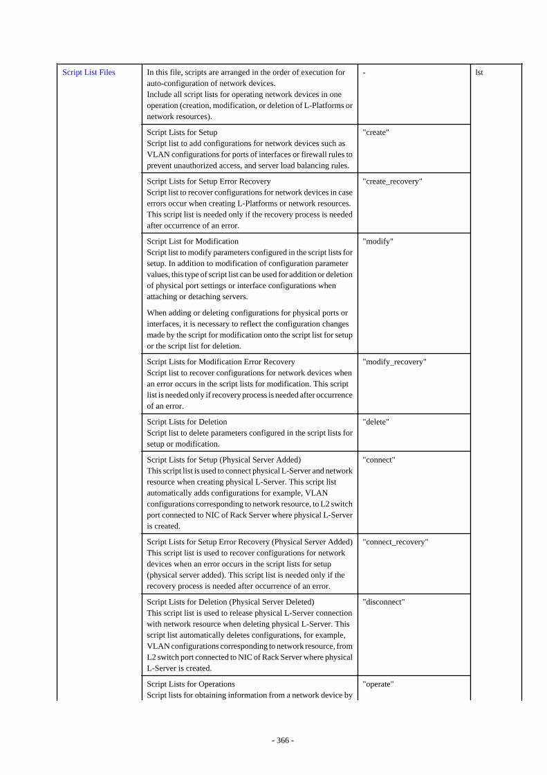
Script List Files In this file, scripts are arranged in the order of execution forauto-configuration of network devices.Include all script lists for operating network devices in oneoperation (creation, modification, or deletion of L-Platforms ornetwork resources).
- lst
Script Lists for SetupScript list to add configurations for network devices such asVLAN configurations for ports of interfaces or firewall rules toprevent unauthorized access, and server load balancing rules.
"create"
Script Lists for Setup Error RecoveryScript list to recover configurations for network devices in caseerrors occur when creating L-Platforms or network resources.This script list is needed only if the recovery process is neededafter occurrence of an error.
"create_recovery"
Script List for ModificationScript list to modify parameters configured in the script lists forsetup. In addition to modification of configuration parametervalues, this type of script list can be used for addition or deletionof physical port settings or interface configurations whenattaching or detaching servers.
When adding or deleting configurations for physical ports orinterfaces, it is necessary to reflect the configuration changesmade by the script for modification onto the script list for setupor the script list for deletion.
"modify"
Script Lists for Modification Error RecoveryScript list to recover configurations for network devices whenan error occurs in the script lists for modification. This scriptlist is needed only if recovery process is needed after occurrenceof an error.
"modify_recovery"
Script Lists for DeletionScript list to delete parameters configured in the script lists forsetup or modification.
"delete"
Script Lists for Setup (Physical Server Added)This script list is used to connect physical L-Server and networkresource when creating physical L-Server. This script listautomatically adds configurations for example, VLANconfigurations corresponding to network resource, to L2 switchport connected to NIC of Rack Server where physical L-Serveris created.
"connect"
Script Lists for Setup Error Recovery (Physical Server Added)This script list is used to recover configurations for networkdevices when an error occurs in the script lists for setup(physical server added). This script list is needed only if therecovery process is needed after occurrence of an error.
"connect_recovery"
Script Lists for Deletion (Physical Server Deleted)This script list is used to release physical L-Server connectionwith network resource when deleting physical L-Server. Thisscript list automatically deletes configurations, for example,VLAN configurations corresponding to network resource, fromL2 switch port connected to NIC of Rack Server where physicalL-Server is created.
"disconnect"
Script Lists for OperationsScript lists for obtaining information from a network device by
"operate"
- 366 -
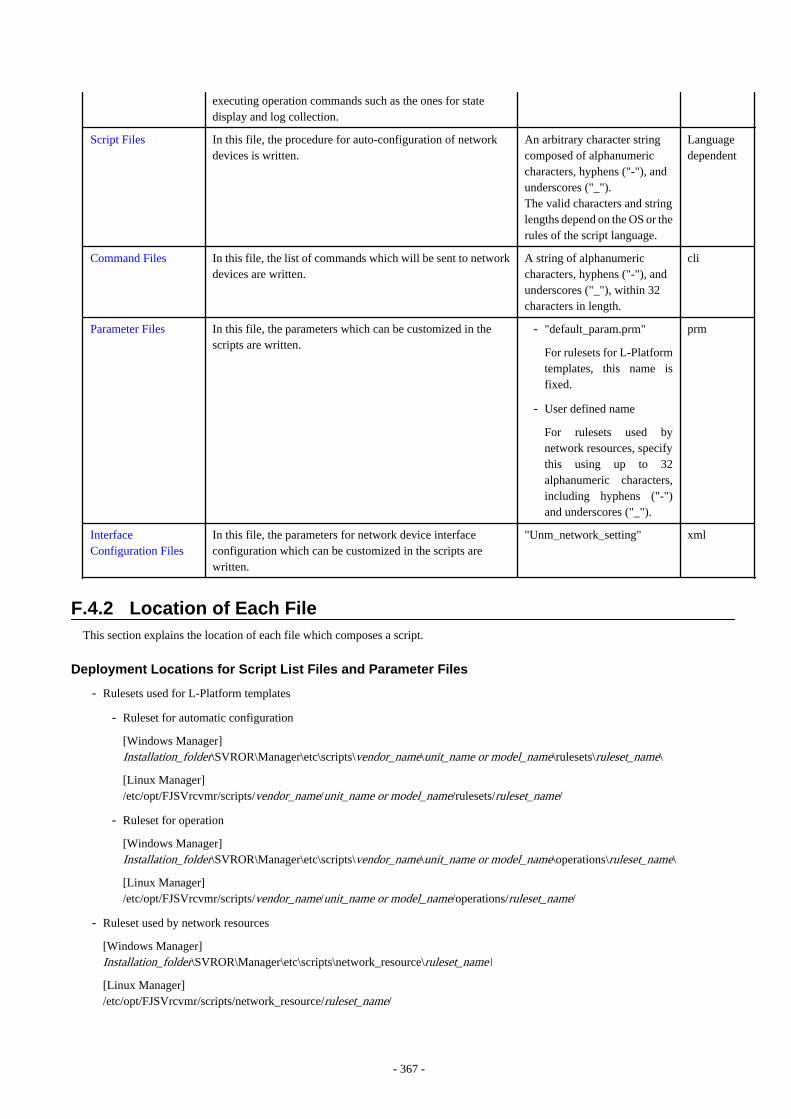
executing operation commands such as the ones for statedisplay and log collection.
Script Files In this file, the procedure for auto-configuration of networkdevices is written.
An arbitrary character stringcomposed of alphanumericcharacters, hyphens ("-"), andunderscores ("_").The valid characters and stringlengths depend on the OS or therules of the script language.
Languagedependent
Command Files In this file, the list of commands which will be sent to networkdevices are written.
A string of alphanumericcharacters, hyphens ("-"), andunderscores ("_"), within 32characters in length.
cli
Parameter Files In this file, the parameters which can be customized in thescripts are written.
- "default_param.prm"
For rulesets for L-Platformtemplates, this name isfixed.
- User defined name
For rulesets used bynetwork resources, specifythis using up to 32alphanumeric characters,including hyphens ("-")and underscores ("_").
prm
InterfaceConfiguration Files
In this file, the parameters for network device interfaceconfiguration which can be customized in the scripts arewritten.
"Unm_network_setting" xml
F.4.2 Location of Each FileThis section explains the location of each file which composes a script.
Deployment Locations for Script List Files and Parameter Files
- Rulesets used for L-Platform templates
- Ruleset for automatic configuration
[Windows Manager]Installation_folder\SVROR\Manager\etc\scripts\vendor_name\unit_name or model_name\rulesets\ruleset_name\
[Linux Manager]/etc/opt/FJSVrcvmr/scripts/vendor_name/unit_name or model_name/rulesets/ruleset_name/
- Ruleset for operation
[Windows Manager]Installation_folder\SVROR\Manager\etc\scripts\vendor_name\unit_name or model_name\operations\ruleset_name\
[Linux Manager]/etc/opt/FJSVrcvmr/scripts/vendor_name/unit_name or model_name/operations/ruleset_name/
- Ruleset used by network resources
[Windows Manager]Installation_folder\SVROR\Manager\etc\scripts\network_resource\ruleset_name\
[Linux Manager]/etc/opt/FJSVrcvmr/scripts/network_resource/ruleset_name/
- 367 -

Deployment Locations for Script Files and Command Files
- Ruleset for automatic configuration
[Windows Manager]Installation_folder\SVROR\Manager\etc\scripts\vendor_name\unit_name or model_name\rulesets\ruleset_name\
[Linux Manager]/etc/opt/FJSVrcvmr/scripts/vendor_name/unit_name or model_name/rulesets/ruleset_name/
- Ruleset for operation
[Windows Manager]Installation_folder\SVROR\Manager\etc\scripts\vendor_name\unit_name or model_name\operations\ruleset_name\
[Linux Manager]/etc/opt/FJSVrcvmr/scripts/vendor_name/unit_name or model_name/operations/ruleset_name/
Deployment Location for Interface Configuration Files
[Windows Manager]Installation_folder\SVROR\Manager\etc\scripts\network_resource\
[Linux Manager]/etc/opt/FJSVrcvmr/scripts/network_resource/
F.5 Timing of Ruleset ExecutionThe timing at which rulesets in the folder for ruleset registration are executed is listed below.
Table F.2 Timing of Ruleset Execution
Operation Registration Folder Target Device Remarks
L-Platform creationL-Platform modificationL-Platform deletion
Folders for L-PlatformTemplates(automatic configuration)
FirewallSets the initial firewallrule.
Server Load Balancer
Folders for Network Resources L2 Switch
When deploying a physicalL-Server using a rackmount server, configure anL2 switch.
Update using "settings" in "L-Platform Details" Folders for L-Platform
Templates(automatic configuration)
Firewall Modifies firewall rules.
Update using "SLB settings" in"L-Platform Details"
Server Load BalancerSets server load balancerrules.
Update using "Operation" in "L-Platform Details" Folders for L-Platform
Templates(operation)
Server Load Balancer
Executes operations.
Update using "Operation log" in"L-Platform Details"
Displays operation logs.
Network resource creationNetwork resource modificationNetwork resource deletion
Folders for Network Resources L2 SwitchSets the VLANcorresponding to networkresources.
F.6 File Components of RulesetsThis section describes each file contents for configuration and operation according to the structure of the script described in "F.4 BasicScript Structure".
- 368 -
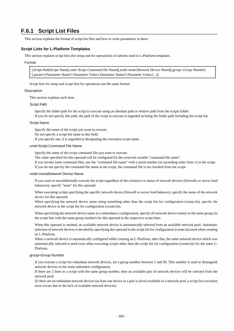
F.6.1 Script List FilesThis section explains the format of script list files and how to write parameters in them.
Script Lists for L-Platform Templates
This section explains script lists (for setup and for operations) of rulesets used in L-Platform templates.
Format
[Script Path]Script Name[,cmd=Script Command file Name][,node=none|Network Device Name][,group=Group Number][,param=(Parameter Name1=Parameter Value1,Parameter Name2=Parameter Value2,...)]
Script lists for setup and script lists for operations use the same format.
Description
This section explains each item.
Script Path
Specify the folder path for the script to execute using an absolute path or relative path from the scripts folder.If you do not specify this path, the path of the script to execute is regarded as being the folder path including the script list.
Script Name
Specify the name of the script you want to execute.Do not specify a script list name in this field.If you specify one, it is regarded as designating the execution script name.
cmd=Script Command File Name
Specify the name of the script command file you want to execute.The value specified for this operand will be configured for the reserved variable "command file name".If you invoke some command files, use the "command file name" with a serial number (in ascending order from 1) in the script.If you do not specify the command file name in the script, the command file is not invoked from the script.
node=none|Network Device Name
If you want to unconditionally execute the script regardless of the existence or status of network devices (firewalls or server loadbalancers), specify "none" for this operand.
When executing scripts specifying the specific network device (firewall or server load balancer), specify the name of the networkdevice for this operand.When specifying the network device name using something other than the script list for configuration (create.lst), specify thenetwork device in the script list for configuration (create.lst).
When specifying the network device name in a redundancy configuration, specify all network device names in the same group (inthe script line with the same group number) for this operand in the respective script lines.
When this operand is omitted, an available network device is automatically selected from an available network pool. Automaticselection of network devices is decided by specifying this operand in the script list for configuration (create.lst) used when creatingan L-Platform.When a network device is automatically configured while creating an L-Platform, after that, the same network device which wasautomatically selected is used even when executing scripts other than the script list for configuration (create.lst) for the same L-Platform.
group=Group Number
If you execute a script for redundant network devices, set a group number between 1 and 99. This number is used to distinguishnetwork devices in the same redundant configuration.If there are 2 lines in a script with the same group number, then an available pair of network devices will be selected from thenetwork pool.(If there are no redundant network devices (at least one device in a pair is alive) available in a network pool, a script list executionerror occurs due to the lack of available network devices).
- 369 -

param=(Parameter Name1=Parameter Value1,Parameter Name2=Parameter Value2,...)
If you want to change the configuration values of variable parameters in a parameter file per script list line, specify this operand.Specify all parameter names and changed parameter values that you want to change.If infrastructure administrators want to decide parameter values per script, writing parameters and their values at this operand meansthose variable parameters do not have fixed values in scripts.If tenant users or administrators specify these parameters when creating an L-Platform, the parameter values are used in the script.
Information
- Specified parameters are separated by "," and blank spaces between parameters and "," are ignored.
- The number of lines specified in a script list is limited to 100, excluding comment lines.
- Comments begin with "#" in the first column. Any characters can be used in the comment line.Write comments such as description of executed scripts when necessary.Comments are ignored when script lists are processed.
- Blank lines are regarded as comments and ignored when a script list is processed.
- Scripts in a script list are executed in the defined order.
Execution Image
Script lists are executed in the order of the list.
[Script Path]Script Name1,group=1[,cmd=Command File Name1][Script Path]Script Name2,group=2[,cmd=Command File Name2]
Script List for Network Resources
This section explains the ruleset script list used by network resources.
Format
Script Path Script Name[,cmd=Script Command File Name],node=Network Device Name[,paramfile=Parameter File Name][,param=(Parameter Name1=Parameter Value1,Parameter Name2=Parameter Value2,...)]
Description
This section explains each item.
Script Path
Specify the folder path for the script to execute using an absolute path or relative path from the scripts folder.The folder path, including the execution script, is necessary.
Script Name
Specify the name of the script you want to execute.Do not specify a script list name in this field. If you specify it, it is regarded as designating the name of the script to execute.
cmd=Script Command File Name
Specify the name of the script command file you want to execute.The value specified for this operand will be configured for the reserved variable "command file name".If you invoke multiple command files, it is necessary to use the "command file names" including a serial number (in ascendingorder from 1).If you do not specify the command file name in the script, the command file is not invoked from the script.
node=Network Device Name
Specify the name of the network device to execute the script.If you specify the wrong network device name in this field, an automatic configuration error or incorrect configuration occurs whenthe script is executed. Specify the network device name carefully.
- 370 -

paramfile=Parameter File Name
Specify the parameter file name of the variable information passed to the script.If you use variable information from a parameter file, specify the name of the parameter file.
param=(Parameter Name1=Parameter Value1,Parameter Name2=Parameter Value2,...)
If you want to change the settings of variable parameters in the parameter file specified for the "paramfile" field per line of scriptlist, use this operand.Specify all parameter names and changed parameter values that you want to change.
Information
- Specified parameters are separated by "," and blank spaces between parameters and "," are ignored.
- The number of lines specified in a script list is limited to 100, excluding comment lines.
- Comments begin with "#" in the first column. Any characters can be used in the comment line.Write comments such as description of executed scripts when necessary.Comments are ignored when script lists are processed.
- Blank lines are regarded as comments and ignored when a script list is processed.
- When a script list processes the same network device, the script list is not executed at the same time but executed in order. On theother hand, when a script list does not process the same network device, the script list is executed at the same time.
Execution Image
Script lists are executed in the order of the list.
[Script Path]Script Name1,node=Network Device Name1,param=(Parameter Name1=Value,...)[Script Path]Script Name2,node=Network Device Name2,param=(Parameter Name2=Value,...)[Script Path]Script Name3,node=Network Device Name3,param=(Parameter Name3=Value,...)
Differences Between Script Lists of L-Platform templates and Network Resources
This section explains the differences between script lists of L-Platform templates and network resources.
Table F.3 Differences Between Script Lists
Item Folders for L-Platform Templates Folders for Network Resources
node operand:network device name configured by scripts
Network devices cannot be specified. Thenetwork device is automatically selected.
"none" can be specified when the script isnot related to the specified network device.
Can be specified
group operand:The number to distinguish a network devicein a redundant configuration
Can be specified Cannot be specified
paramfile operand:parameter file name
Cannot be specified Can be specified
F.6.2 Script FilesThis section explains how to create script files.
- 371 -
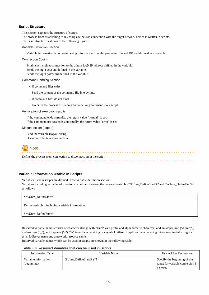
Script Structure
This section explains the structure of scripts.The process from establishing to releasing a telnet/ssh connection with the target network device is written in scripts.The basic structure is shown in the following figure.
Variable Definition Section
Variable information is converted using information from the parameter file and DB and defined as a variable.
Connection (login)
Establishes a telnet connection to the admin LAN IP address defined in the variable.Sends the login account defined in the variable.Sends the login password defined in the variable.
Command Sending Section
- If command files exist
Send the content of the command file line by line.
- If command files do not exist
Executes the process of sending and receiving commands in a script.
Verification of execution results
If the command ends normally, the return value "normal" is set.If the command process ends abnormally, the return value "error" is set.
Disconnection (logout)
Send the variable (logout string).Disconnect the telnet connection.
Note
Define the process from connection to disconnection in the script.
Variable Information Usable in Scripts
Variables used in scripts are defined in the variable definition section.Variables including variable information are defined between the reserved variables "%Unm_DefineStart%" and "%Unm_DefineEnd%"as follows.
# %Unm_DefineStart%
Define variables, including variable information.
# %Unm_DefineEnd%
Reserved variable names consist of character strings with "Unm" as a prefix and alphanumeric characters and an ampersand ("&"),underscores ("_"), and hyphens ("-"). "&" in a character string is a symbol utilized to split a character string into a meaningful string suchas an L-Server name and a network resource name.Reserved variable names which can be used in scripts are shown in the following table.
Table F.4 Reserved Variables that can be Used in Scripts
Information Type Variable Name Usage After Conversion
Variable information(beginning)
%Unm_DefineStart% (*1) Specify the beginning of therange for variable conversion ina script.
- 372 -
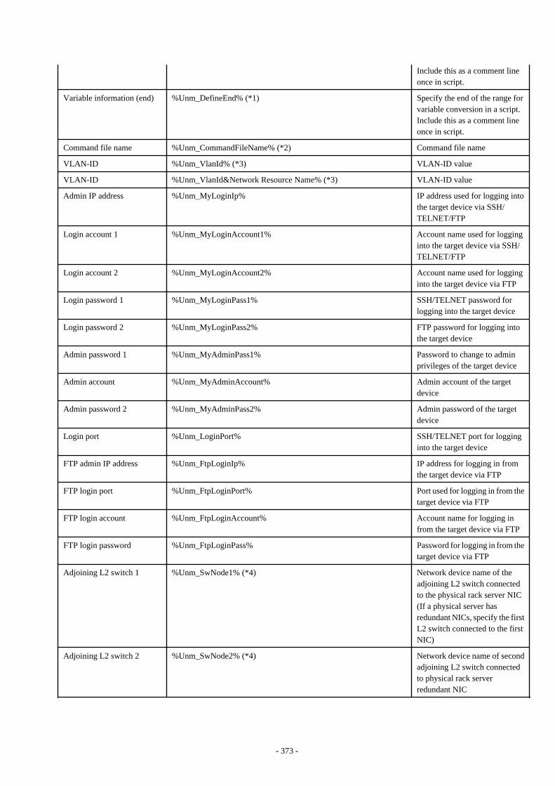
Include this as a comment lineonce in script.
Variable information (end) %Unm_DefineEnd% (*1) Specify the end of the range forvariable conversion in a script.Include this as a comment lineonce in script.
Command file name %Unm_CommandFileName% (*2) Command file name
VLAN-ID %Unm_VlanId% (*3) VLAN-ID value
VLAN-ID %Unm_VlanId&Network Resource Name% (*3) VLAN-ID value
Admin IP address %Unm_MyLoginIp% IP address used for logging intothe target device via SSH/TELNET/FTP
Login account 1 %Unm_MyLoginAccount1% Account name used for logginginto the target device via SSH/TELNET/FTP
Login account 2 %Unm_MyLoginAccount2% Account name used for logginginto the target device via FTP
Login password 1 %Unm_MyLoginPass1% SSH/TELNET password forlogging into the target device
Login password 2 %Unm_MyLoginPass2% FTP password for logging intothe target device
Admin password 1 %Unm_MyAdminPass1% Password to change to adminprivileges of the target device
Admin account %Unm_MyAdminAccount% Admin account of the targetdevice
Admin password 2 %Unm_MyAdminPass2% Admin password of the targetdevice
Login port %Unm_LoginPort% SSH/TELNET port for logginginto the target device
FTP admin IP address %Unm_FtpLoginIp% IP address for logging in fromthe target device via FTP
FTP login port %Unm_FtpLoginPort% Port used for logging in from thetarget device via FTP
FTP login account %Unm_FtpLoginAccount% Account name for logging infrom the target device via FTP
FTP login password %Unm_FtpLoginPass% Password for logging in from thetarget device via FTP
Adjoining L2 switch 1 %Unm_SwNode1% (*4) Network device name of theadjoining L2 switch connectedto the physical rack server NIC(If a physical server hasredundant NICs, specify the firstL2 switch connected to the firstNIC)
Adjoining L2 switch 2 %Unm_SwNode2% (*4) Network device name of secondadjoining L2 switch connectedto physical rack serverredundant NIC
- 373 -
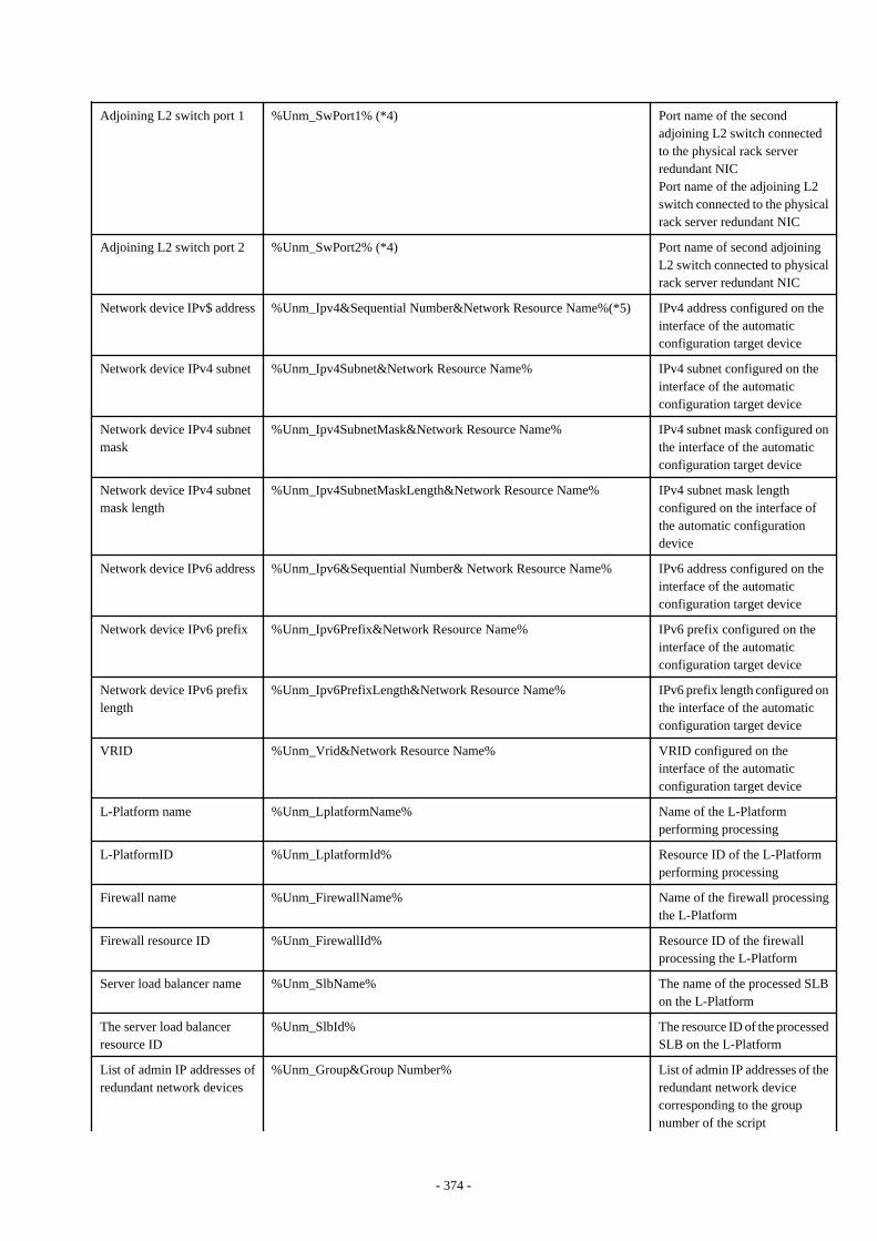
Adjoining L2 switch port 1 %Unm_SwPort1% (*4) Port name of the secondadjoining L2 switch connectedto the physical rack serverredundant NICPort name of the adjoining L2switch connected to the physicalrack server redundant NIC
Adjoining L2 switch port 2 %Unm_SwPort2% (*4) Port name of second adjoiningL2 switch connected to physicalrack server redundant NIC
Network device IPv$ address %Unm_Ipv4&Sequential Number&Network Resource Name%(*5) IPv4 address configured on theinterface of the automaticconfiguration target device
Network device IPv4 subnet %Unm_Ipv4Subnet&Network Resource Name% IPv4 subnet configured on theinterface of the automaticconfiguration target device
Network device IPv4 subnetmask
%Unm_Ipv4SubnetMask&Network Resource Name% IPv4 subnet mask configured onthe interface of the automaticconfiguration target device
Network device IPv4 subnetmask length
%Unm_Ipv4SubnetMaskLength&Network Resource Name% IPv4 subnet mask lengthconfigured on the interface ofthe automatic configurationdevice
Network device IPv6 address %Unm_Ipv6&Sequential Number& Network Resource Name% IPv6 address configured on theinterface of the automaticconfiguration target device
Network device IPv6 prefix %Unm_Ipv6Prefix&Network Resource Name% IPv6 prefix configured on theinterface of the automaticconfiguration target device
Network device IPv6 prefixlength
%Unm_Ipv6PrefixLength&Network Resource Name% IPv6 prefix length configured onthe interface of the automaticconfiguration target device
VRID %Unm_Vrid&Network Resource Name% VRID configured on theinterface of the automaticconfiguration target device
L-Platform name %Unm_LplatformName% Name of the L-Platformperforming processing
L-PlatformID %Unm_LplatformId% Resource ID of the L-Platformperforming processing
Firewall name %Unm_FirewallName% Name of the firewall processingthe L-Platform
Firewall resource ID %Unm_FirewallId% Resource ID of the firewallprocessing the L-Platform
Server load balancer name %Unm_SlbName% The name of the processed SLBon the L-Platform
The server load balancerresource ID
%Unm_SlbId% The resource ID of the processedSLB on the L-Platform
List of admin IP addresses ofredundant network devices
%Unm_Group&Group Number% List of admin IP addresses of theredundant network devicecorresponding to the groupnumber of the script
- 374 -
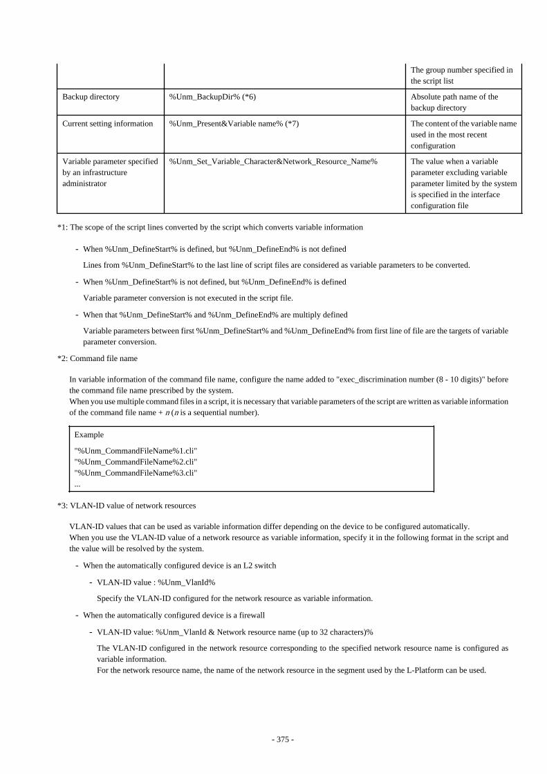
The group number specified inthe script list
Backup directory %Unm_BackupDir% (*6) Absolute path name of thebackup directory
Current setting information %Unm_Present&Variable name% (*7) The content of the variable nameused in the most recentconfiguration
Variable parameter specifiedby an infrastructureadministrator
%Unm_Set_Variable_Character&Network_Resource_Name% The value when a variableparameter excluding variableparameter limited by the systemis specified in the interfaceconfiguration file
*1: The scope of the script lines converted by the script which converts variable information
- When %Unm_DefineStart% is defined, but %Unm_DefineEnd% is not defined
Lines from %Unm_DefineStart% to the last line of script files are considered as variable parameters to be converted.
- When %Unm_DefineStart% is not defined, but %Unm_DefineEnd% is defined
Variable parameter conversion is not executed in the script file.
- When that %Unm_DefineStart% and %Unm_DefineEnd% are multiply defined
Variable parameters between first %Unm_DefineStart% and %Unm_DefineEnd% from first line of file are the targets of variableparameter conversion.
*2: Command file name
In variable information of the command file name, configure the name added to "exec_discrimination number (8 - 10 digits)" beforethe command file name prescribed by the system.When you use multiple command files in a script, it is necessary that variable parameters of the script are written as variable informationof the command file name + n (n is a sequential number).
Example
"%Unm_CommandFileName%1.cli""%Unm_CommandFileName%2.cli""%Unm_CommandFileName%3.cli"...
*3: VLAN-ID value of network resources
VLAN-ID values that can be used as variable information differ depending on the device to be configured automatically.When you use the VLAN-ID value of a network resource as variable information, specify it in the following format in the script andthe value will be resolved by the system.
- When the automatically configured device is an L2 switch
- VLAN-ID value : %Unm_VlanId%
Specify the VLAN-ID configured for the network resource as variable information.
- When the automatically configured device is a firewall
- VLAN-ID value: %Unm_VlanId & Network resource name (up to 32 characters)%
The VLAN-ID configured in the network resource corresponding to the specified network resource name is configured asvariable information.For the network resource name, the name of the network resource in the segment used by the L-Platform can be used.
- 375 -

- When the automatically configured device is a server load balancer
- VLAN-ID value: %Unm_VlanId & Network resource name (up to 32 characters)%
The VLAN-ID configured in the network resource corresponding to the specified network resource name is configured asvariable information.For the network resource name, the name of the network resource in the segment where the server load balancer is locatedcan be used.
*4: Reserved variable names when physical rack servers have redundant NICs
For a physical rack server with redundant NICs, the reserved variable names are as follow:
Figure F.4 Reserved Variable Names for Physical Rack Mount Servers with Redundant NICs
*5: Sequential numbers
Ensure that specified sequential numbers are the values corresponding to the IPv4/IPv6 addresses for the desired purpose.Assign sequential numbers for each purpose to the IPv4/IPv6 addresses required by network devices, such as physical IPv4/IPv6addresses for active units and virtual IPv4/IPv6 addresses for standby units.Specify the mapping of the IPv4/IPv6 addresses for each purpose and assign sequential numbers in the following elements in theinterface configuration file:
- The IPv4Address element
- The IPv4Address element
*6: Backup directory
Parameters in the following definition files are configured as a backup directory name.
- Storage Location of the Definition File
[Windows Manager]Installation_folder\SVROR\Manager\etc\customize_data\manager_backup.rcxprop
- 376 -
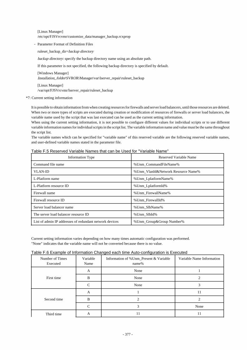
[Linux Manager]/etc/opt/FJSVrcvmr/customize_data/manager_backup.rcxprop
- Parameter Format of Definition Files
ruleset_backup_dir=backup directory
backup directory: specify the backup directory name using an absolute path.
If this parameter is not specified, the following backup directory is specified by default.
[Windows Manager]Installation_folder\SVROR\Manager\var\lserver_repair\ruleset_backup
[Linux Manager]/var/opt/FJSVrcvmr/lserver_repair/ruleset_backup
*7: Current setting information
It is possible to obtain information from when creating resources for firewalls and server load balancers, until those resources are deleted.When two or more types of scripts are executed during creation or modification of resources of firewalls or server load balancers, thevariable name used by the script that was last executed can be used as the current setting information.When using the current setting information, it is not possible to configure different values for individual scripts or to use differentvariable information names for individual scripts in the script list. The variable information name and value must be the same throughoutthe script list.The variable names which can be specified for "variable name" of this reserved variable are the following reserved variable names,and user-defined variable names stated in the parameter file.
Table F.5 Reserved Variable Names that can be Used for "Variable Name"
Information Type Reserved Variable Name
Command file name %Unm_CommandFileName%
VLAN-ID %Unm_VlanId&Network Resource Name%
L-Platform name %Unm_LplatformName%
L-Platform resource ID %Unm_LplatformId%
Firewall name %Unm_FirewallName%
Firewall resource ID %Unm_FirewallId%
Server load balancer name %Unm_SlbName%
The server load balancer resource ID %Unm_SlbId%
List of admin IP addresses of redundant network devices %Unm_Group&Group Number%
Current setting information varies depending on how many times automatic configuration was performed."None" indicates that the variable name will not be converted because there is no value.
Table F.6 Example of Information Changed each time Auto-configuration is Executed
Number of TimesExecuted
VariableName
Information of %Unm_Present & Variablename%
Variable Name Information
First time
A None 1
B None 2
C None 3
Second time
A 1 11
B 2 2
C 3 None
Third time A 11 11
- 377 -
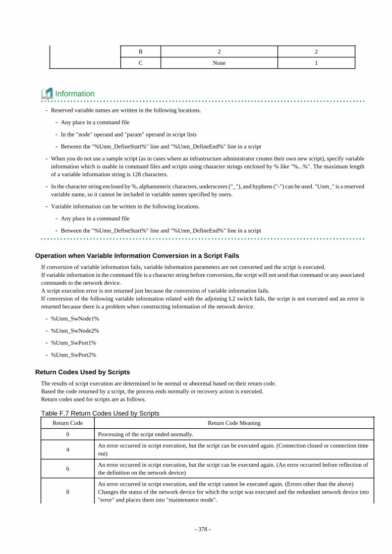
B 2 2
C None 1
Information
- Reserved variable names are written in the following locations.
- Any place in a command file
- In the "node" operand and "param" operand in script lists
- Between the "%Unm_DefineStart%" line and "%Unm_DefineEnd%" line in a script
- When you do not use a sample script (as in cases where an infrastructure administrator creates their own new script), specify variableinformation which is usable in command files and scripts using character strings enclosed by % like "%...%". The maximum lengthof a variable information string is 128 characters.
- In the character string enclosed by %, alphanumeric characters, underscores ("_"), and hyphens ("-") can be used. "Unm_" is a reservedvariable name, so it cannot be included in variable names specified by users.
- Variable information can be written in the following locations.
- Any place in a command file
- Between the "%Unm_DefineStart%" line and "%Unm_DefineEnd%" line in a script
Operation when Variable Information Conversion in a Script Fails
If conversion of variable information fails, variable information parameters are not converted and the script is executed.If variable information in the command file is a character string before conversion, the script will not send that command or any associatedcommands to the network device.A script execution error is not returned just because the conversion of variable information fails.If conversion of the following variable information related with the adjoining L2 switch fails, the script is not executed and an error isreturned because there is a problem when constructing information of the network device.
- %Unm_SwNode1%
- %Unm_SwNode2%
- %Unm_SwPort1%
- %Unm_SwPort2%
Return Codes Used by Scripts
The results of script execution are determined to be normal or abnormal based on their return code.Based the code returned by a script, the process ends normally or recovery action is executed.Return codes used for scripts are as follows.
Table F.7 Return Codes Used by Scripts
Return Code Return Code Meaning
0 Processing of the script ended normally.
4An error occurred in script execution, but the script can be executed again. (Connection closed or connection timeout)
6An error occurred in script execution, but the script can be executed again. (An error occurred before reflection ofthe definition on the network device)
8An error occurred in script execution, and the script cannot be executed again. (Errors other than the above)Changes the status of the network device for which the script was executed and the redundant network device into"error" and places them into "maintenance mode".
- 378 -
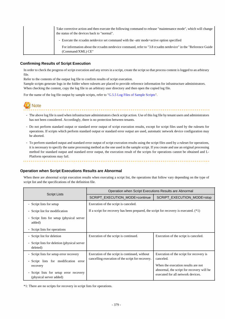
Take corrective action and then execute the following command to release "maintenance mode", which will changethe status of the devices back to "normal".
- Execute the rcxadm netdevice set command with the -attr mode=active option specified
For information about the rcxadm netdevice command, refer to "3.8 rcxadm netdevice" in the "Reference Guide(Command/XML) CE"
Confirming Results of Script Execution
In order to check the progress of script execution and any errors in a script, create the script so that process content is logged to an arbitraryfile.Refer to the contents of the output log file to confirm results of script execution.Sample scripts generate logs in the folder where rulesets are placed to provide reference information for infrastructure administrators.When checking the content, copy the log file to an arbitrary user directory and then open the copied log file.
For the name of the log file output by sample scripts, refer to "G.5.5 Log Files of Sample Scripts".
Note
- The above log file is used when infrastructure administrators check script action. Use of this log file by tenant users and administratorshas not been considered. Accordingly, there is no protection between tenants.
- Do not perform standard output or standard error output of script execution results, except for script files used by the rulesets foroperations. If scripts which perform standard output or standard error output are used, automatic network device configuration maybe aborted.
- To perform standard output and standard error output of script execution results using the script files used by a ruleset for operations,it is necessary to specify the same processing method as the one used in the sample script. If you create and use an original processingmethod for standard output and standard error output, the execution result of the scripts for operations cannot be obtained and L-Platform operations may fail.
Operation when Script Executions Results are Abnormal
When there are abnormal script execution results when executing a script list, the operations that follow vary depending on the type ofscript list and the specifications of the definition file.
Script ListsOperation when Script Executions Results are Abnormal
SCRIPT_EXECUTION_MODE=continue SCRIPT_EXECUTION_MODE=stop
- Script lists for setup
- Script list for modification
- Script lists for setup (physical serveradded)
- Script lists for operations
Execution of the script is canceled.
If a script for recovery has been prepared, the script for recovery is executed. (*1)
- Script list for deletion
- Script lists for deletion (physical serverdeleted)
Execution of the script is continued. Execution of the script is canceled.
- Script lists for setup error recovery
- Script lists for modification errorrecovery
- Script lists for setup error recovery(physical server added)
Execution of the script is continued, withoutcancelling execution of the script for recovery.
Execution of the script for recovery iscanceled.
When the execution results are notabnormal, the script for recovery will beexecuted for all network devices.
*1: There are no scripts for recovery in script lists for operations.
- 379 -
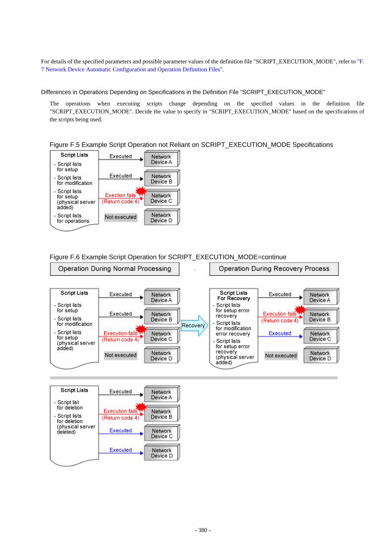
For details of the specified parameters and possible parameter values of the definition file "SCRIPT_EXECUTION_MODE", refer to "F.7 Network Device Automatic Configuration and Operation Definition Files".
Differences in Operations Depending on Specifications in the Definition File "SCRIPT_EXECUTION_MODE"
The operations when executing scripts change depending on the specified values in the definition file"SCRIPT_EXECUTION_MODE". Decide the value to specify in "SCRIPT_EXECUTION_MODE" based on the specifications ofthe scripts being used.
Figure F.5 Example Script Operation not Reliant on SCRIPT_EXECUTION_MODE Specifications
Figure F.6 Example Script Operation for SCRIPT_EXECUTION_MODE=continue
- 380 -
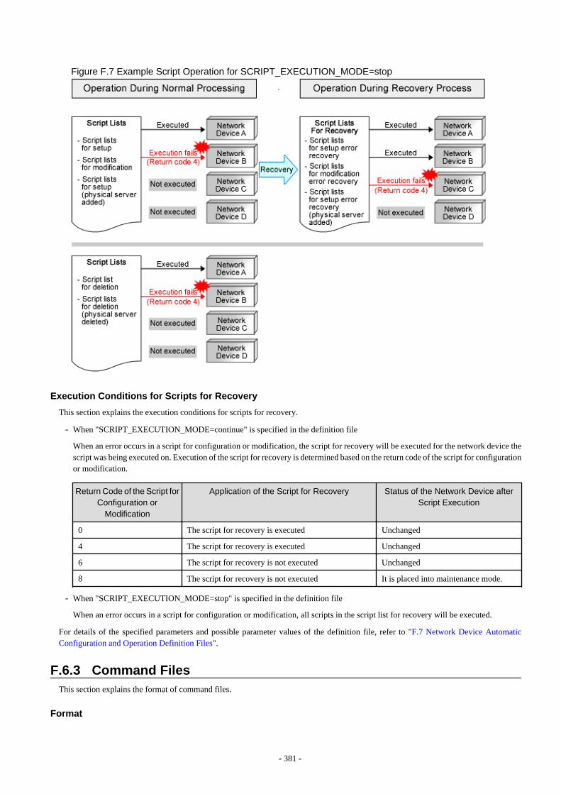
Figure F.7 Example Script Operation for SCRIPT_EXECUTION_MODE=stop
Execution Conditions for Scripts for Recovery
This section explains the execution conditions for scripts for recovery.
- When "SCRIPT_EXECUTION_MODE=continue" is specified in the definition file
When an error occurs in a script for configuration or modification, the script for recovery will be executed for the network device thescript was being executed on. Execution of the script for recovery is determined based on the return code of the script for configurationor modification.
Return Code of the Script for
Configuration orModification
Application of the Script for Recovery Status of the Network Device afterScript Execution
0 The script for recovery is executed Unchanged
4 The script for recovery is executed Unchanged
6 The script for recovery is not executed Unchanged
8 The script for recovery is not executed It is placed into maintenance mode.
- When "SCRIPT_EXECUTION_MODE=stop" is specified in the definition file
When an error occurs in a script for configuration or modification, all scripts in the script list for recovery will be executed.
For details of the specified parameters and possible parameter values of the definition file, refer to "F.7 Network Device AutomaticConfiguration and Operation Definition Files".
F.6.3 Command FilesThis section explains the format of command files.
Format
- 381 -

Command for Network Device.....Command for Network Device
Only include commands for the target network device in the command file.
Information
- Command format depends on the type of network device.
- When creating scripts referring to sample scripts, initial commands executed after logging in to a network device depend on the typeof network device. So, it is necessary to change the initial commands and their responses in the script.
- If the structure of a script is same as that of a sample script, commands in the command file are executed after the execution of initialcommands.
Creation Example
class-map match-all %classmapname%match source-address ip %ip%match source-port %port%match destination-address ip %Unm_IPv4& LServer_name&network_resource_name %match destination-port %serverport%...interface %ifname%rule access %num% in %classmapname% accept audit-session-norma audit-match-none...commitsave startup-config
Point
- All variable information in a command file is within the conversion range and converted before script execution.For the variable information which can be used, refer to "Variable Information Usable in Scripts".
- When not using any sample scripts (such as when the infrastructure administrator creates their own new script), create command filesin the appropriate format for the created script.
- When scripts do not invoke command files, such as when not using sample scripts, it is no necessary to create a command file.
F.6.4 Parameter FilesThis section explains the format of the parameter file.
Format
The parameter file is in XML format.Refer to "15.15 Parameter Files (for Scripts)" in the "Reference Guide (Command/XML) CE" for details.
F.6.5 Interface Configuration FilesThis section explains the format of the interface configuration file.
Format
The interface configuration file is in XML format.Refer to "15.16 Network Device Interface Configuration File" in the "Reference Guide (Command/XML) CE" for details.
- 382 -
F.6.6 In Advance Script Operation ChecksThis appendix explains the procedure for checking the operation of created scripts in advance.
Please perform checks in a separate environment in order to prevent the operation check affecting the operational environment.
Operation Checks of Scripts other than "Variable Information"
Check the operation of scripts excluding their "variable information".
1. Prepare the network devices to use for the operation check.Prepare a network using network devices other than those used in the operating public LAN and admin LAN.
2. Register the network devices for the operation check.When using firewalls or server load balancers, create a network pool for the operation check and then register the network devices.
3. Prepare the script for the operation check, basing it on the script you plan to use in actual operation.At this time, make the following modifications to enable the operation check.
- Replace the "variable information" of the script with the post-conversion values.
- Change the log output settings to save the log in the desired location so that the execution results can be checked.
4. Use the auto-configuration function to perform auto-configuration of the network devices to be used in the operation check.
5. Check the operation results of the script in the output log.
6. Connect to the network devices and delete the definition set for the operation check.
Conversion Checks of "Variable Information"
Check whether the "variable information" specified in the script file and command file was converted as intended.
1. Prepare the network devices to use for the operation check.Prepare a network using network devices other than those used in the operating public LAN and admin LAN.
2. Register the network devices for the operation check.When using firewalls or server load balancers, create a network pool for the operation check and then register the network devices.
3. Prepare the script that will be used in actual operation as the operation check script.
- As configuration of network devices is not necessary, change the script to finish before it connects to the network devices.
- Change the settings to save the log in the desired location so that the post-conversion "variable information" can be checked.
4. Use the auto-configuration function to perform auto-configuration of the network devices to be used in the operation check.
- 383 -
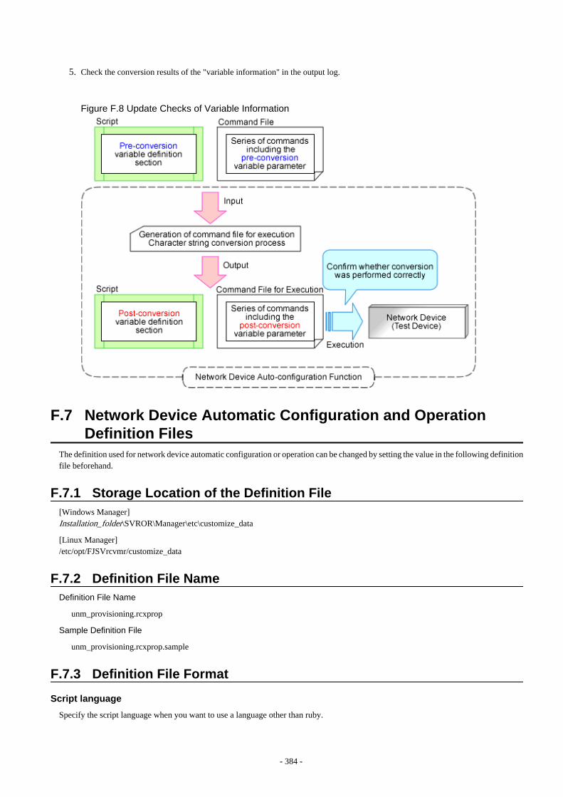
5. Check the conversion results of the "variable information" in the output log.
Figure F.8 Update Checks of Variable Information
F.7 Network Device Automatic Configuration and OperationDefinition Files
The definition used for network device automatic configuration or operation can be changed by setting the value in the following definitionfile beforehand.
F.7.1 Storage Location of the Definition File[Windows Manager]Installation_folder\SVROR\Manager\etc\customize_data
[Linux Manager]/etc/opt/FJSVrcvmr/customize_data
F.7.2 Definition File NameDefinition File Name
unm_provisioning.rcxprop
Sample Definition File
unm_provisioning.rcxprop.sample
F.7.3 Definition File Format
Script language
Specify the script language when you want to use a language other than ruby.
- 384 -
Information
Ruby is used as the script language in sample scripts.
Parameter Format of Definition Files
extension_EXTENSION=execution file path
Specify the extension of the script language such as "rb" or "pl" for EXTENSION.
When there is no specification for the EXTENSION jruby is used.
Execution file path specifies the absolute path.
Example
extension_rb=/usr/bin/jruby
Monitoring Time of Script
Specify the monitoring time when you want to change it to a value besides 300(s).
Information
In the network device automatic configuration function, script execution time is monitored.When the monitoring time has passed since the beginning of the script execution, the processing of the script is terminated.
Parameter Format of Definition Files
EXECUTE_TIMEOUT=monitoring time
Specify the monitoring time within the range of 1 to 7200(s).
When the specified value is non-numeric or is outside of the above-mentioned range, 300(s) is used.
Example
EXECUTE_TIMEOUT=600
Upper Output Limit of Operation Rulesets
Specify the upper output limit of operation ruleset when you want to change it to a value other than 500 (KB).
Information
When a large amount of data is output as a result of executing a ruleset for operations on network devices, a large amount of memoryresources is consumed. Memory consumption can be limited by customizing the upper output limit.
Parameter Format of Definition Files
SCRIPT_OUTPUT_SIZE_LIMIT= upper output limit
Specify the upper output limit within the range of 1-10000 (KB).
When the specified value is non-numeric or is outside the range mentioned above, 500 (KB) is used.
- 385 -
Example
SCRIPT_OUTPUT_SIZE_LIMIT=300
Operation Specifications when Script Executions Results are Abnormal
This section explains the operations when there are abnormal script execution results when executing a script list. The following scriptlists are the targets.
- Script lists for setup error recovery
- Script lists for modification error recovery
- Script list for deletion
- Script lists for setup error recovery (physical server added)
- Script lists for deletion (physical server deleted)
For details on the operations when scripts are executed based on specified values, refer to "Differences in Operations Depending onSpecifications in the Definition File "SCRIPT_EXECUTION_MODE"".
Information
When using simple configuration, as the scripts are prepared in advance configuration of this definition is not necessary.
Parameter Format of Definition Files
- To execute successive scripts listed in the script list
SCRIPT_EXECUTION_MODE=continue
- To cancel successive scripts listed in the script list
SCRIPT_EXECUTION_MODE=stop
If a value other than continue or stop is specified, or no value is specified, stop will be used.
Example
SCRIPT_EXECUTION_MODE=continue
- 386 -
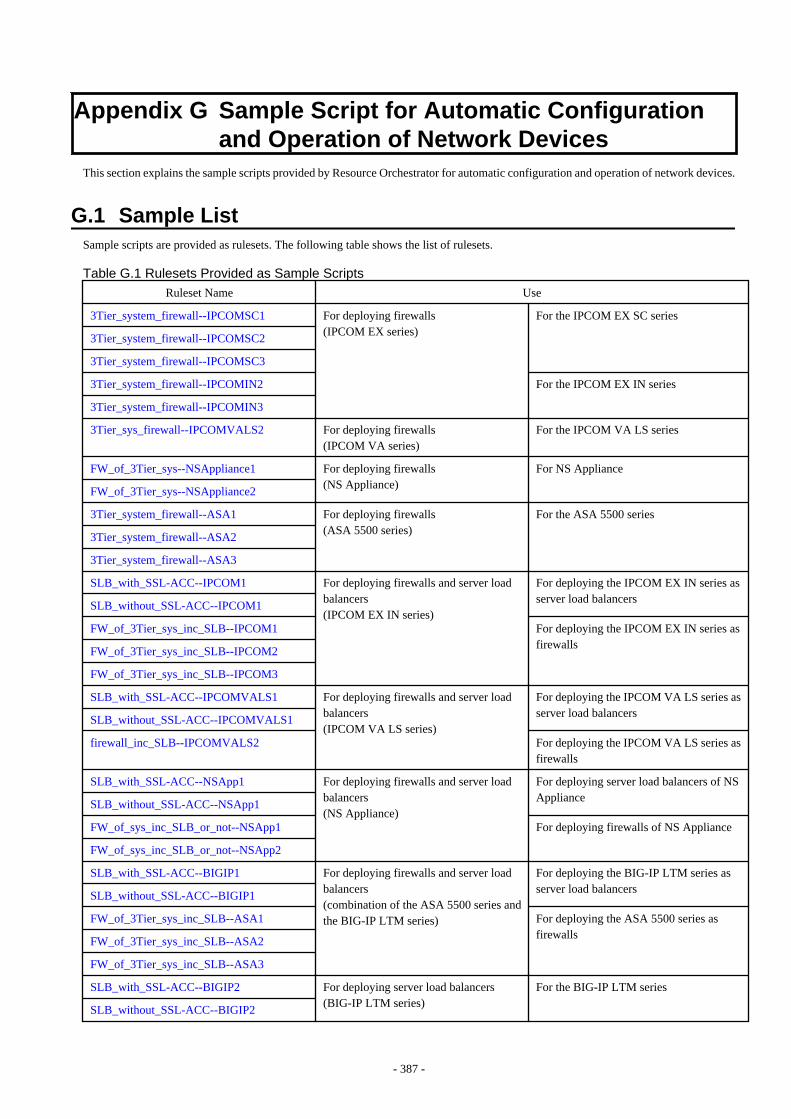
Appendix G Sample Script for Automatic Configurationand Operation of Network Devices
This section explains the sample scripts provided by Resource Orchestrator for automatic configuration and operation of network devices.
G.1 Sample ListSample scripts are provided as rulesets. The following table shows the list of rulesets.
Table G.1 Rulesets Provided as Sample Scripts
Ruleset Name Use
3Tier_system_firewall--IPCOMSC1 For deploying firewalls(IPCOM EX series)
For the IPCOM EX SC series
3Tier_system_firewall--IPCOMSC2
3Tier_system_firewall--IPCOMSC3
3Tier_system_firewall--IPCOMIN2 For the IPCOM EX IN series
3Tier_system_firewall--IPCOMIN3
3Tier_sys_firewall--IPCOMVALS2 For deploying firewalls(IPCOM VA series)
For the IPCOM VA LS series
FW_of_3Tier_sys--NSAppliance1 For deploying firewalls(NS Appliance)
For NS Appliance
FW_of_3Tier_sys--NSAppliance2
3Tier_system_firewall--ASA1 For deploying firewalls(ASA 5500 series)
For the ASA 5500 series
3Tier_system_firewall--ASA2
3Tier_system_firewall--ASA3
SLB_with_SSL-ACC--IPCOM1 For deploying firewalls and server loadbalancers(IPCOM EX IN series)
For deploying the IPCOM EX IN series asserver load balancers
SLB_without_SSL-ACC--IPCOM1
FW_of_3Tier_sys_inc_SLB--IPCOM1 For deploying the IPCOM EX IN series asfirewalls
FW_of_3Tier_sys_inc_SLB--IPCOM2
FW_of_3Tier_sys_inc_SLB--IPCOM3
SLB_with_SSL-ACC--IPCOMVALS1 For deploying firewalls and server loadbalancers(IPCOM VA LS series)
For deploying the IPCOM VA LS series asserver load balancers
SLB_without_SSL-ACC--IPCOMVALS1
firewall_inc_SLB--IPCOMVALS2 For deploying the IPCOM VA LS series asfirewalls
SLB_with_SSL-ACC--NSApp1 For deploying firewalls and server loadbalancers(NS Appliance)
For deploying server load balancers of NSAppliance
SLB_without_SSL-ACC--NSApp1
FW_of_sys_inc_SLB_or_not--NSApp1 For deploying firewalls of NS Appliance
FW_of_sys_inc_SLB_or_not--NSApp2
SLB_with_SSL-ACC--BIGIP1 For deploying firewalls and server loadbalancers(combination of the ASA 5500 series andthe BIG-IP LTM series)
For deploying the BIG-IP LTM series asserver load balancers
SLB_without_SSL-ACC--BIGIP1
FW_of_3Tier_sys_inc_SLB--ASA1 For deploying the ASA 5500 series asfirewalls
FW_of_3Tier_sys_inc_SLB--ASA2
FW_of_3Tier_sys_inc_SLB--ASA3
SLB_with_SSL-ACC--BIGIP2 For deploying server load balancers(BIG-IP LTM series)
For the BIG-IP LTM series
SLB_without_SSL-ACC--BIGIP2
- 387 -
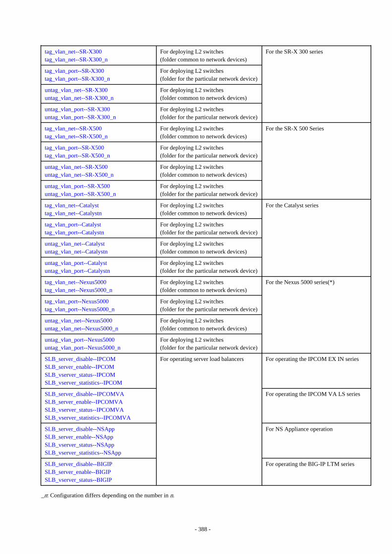
tag_vlan_net--SR-X300tag_vlan_net--SR-X300_n
For deploying L2 switches(folder common to network devices)
For the SR-X 300 series
tag_vlan_port--SR-X300tag_vlan_port--SR-X300_n
For deploying L2 switches(folder for the particular network device)
untag_vlan_net--SR-X300untag_vlan_net--SR-X300_n
For deploying L2 switches(folder common to network devices)
untag_vlan_port--SR-X300untag_vlan_port--SR-X300_n
For deploying L2 switches(folder for the particular network device)
tag_vlan_net--SR-X500tag_vlan_net--SR-X500_n
For deploying L2 switches(folder common to network devices)
For the SR-X 500 Series
tag_vlan_port--SR-X500tag_vlan_port--SR-X500_n
For deploying L2 switches(folder for the particular network device)
untag_vlan_net--SR-X500untag_vlan_net--SR-X500_n
For deploying L2 switches(folder common to network devices)
untag_vlan_port--SR-X500untag_vlan_port--SR-X500_n
For deploying L2 switches(folder for the particular network device)
tag_vlan_net--Catalysttag_vlan_net--Catalystn
For deploying L2 switches(folder common to network devices)
For the Catalyst series
tag_vlan_port--Catalysttag_vlan_port--Catalystn
For deploying L2 switches(folder for the particular network device)
untag_vlan_net--Catalystuntag_vlan_net--Catalystn
For deploying L2 switches(folder common to network devices)
untag_vlan_port--Catalystuntag_vlan_port--Catalystn
For deploying L2 switches(folder for the particular network device)
tag_vlan_net--Nexus5000tag_vlan_net--Nexus5000_n
For deploying L2 switches(folder common to network devices)
For the Nexus 5000 series(*)
tag_vlan_port--Nexus5000tag_vlan_port--Nexus5000_n
For deploying L2 switches(folder for the particular network device)
untag_vlan_net--Nexus5000untag_vlan_net--Nexus5000_n
For deploying L2 switches(folder common to network devices)
untag_vlan_port--Nexus5000untag_vlan_port--Nexus5000_n
For deploying L2 switches(folder for the particular network device)
SLB_server_disable--IPCOMSLB_server_enable--IPCOMSLB_vserver_status--IPCOMSLB_vserver_statistics--IPCOM
For operating server load balancers For operating the IPCOM EX IN series
SLB_server_disable--IPCOMVASLB_server_enable--IPCOMVASLB_vserver_status--IPCOMVASLB_vserver_statistics--IPCOMVA
For operating the IPCOM VA LS series
SLB_server_disable--NSAppSLB_server_enable--NSAppSLB_vserver_status--NSAppSLB_vserver_statistics--NSApp
For NS Appliance operation
SLB_server_disable--BIGIPSLB_server_enable--BIGIPSLB_vserver_status--BIGIP
For operating the BIG-IP LTM series
_n: Configuration differs depending on the number in n.
- 388 -
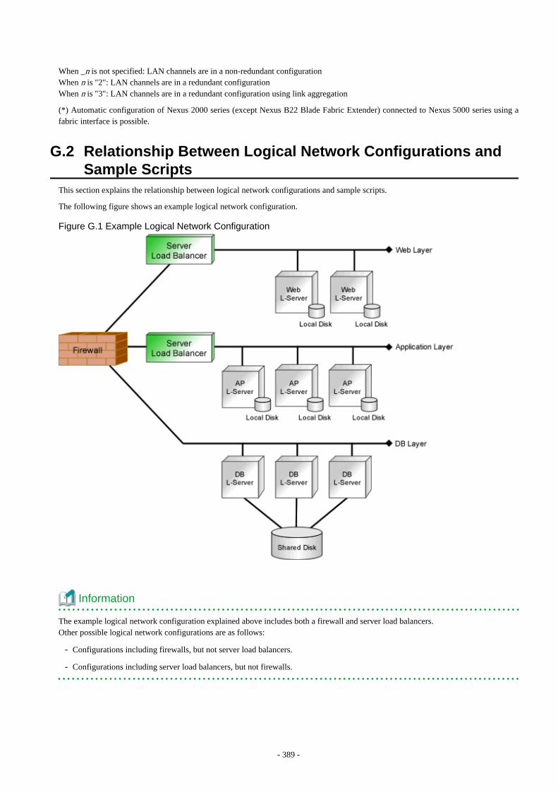
When _n is not specified: LAN channels are in a non-redundant configurationWhen n is "2": LAN channels are in a redundant configurationWhen n is "3": LAN channels are in a redundant configuration using link aggregation
(*) Automatic configuration of Nexus 2000 series (except Nexus B22 Blade Fabric Extender) connected to Nexus 5000 series using afabric interface is possible.
G.2 Relationship Between Logical Network Configurations andSample Scripts
This section explains the relationship between logical network configurations and sample scripts.
The following figure shows an example logical network configuration.
Figure G.1 Example Logical Network Configuration
Information
The example logical network configuration explained above includes both a firewall and server load balancers.Other possible logical network configurations are as follows:
- Configurations including firewalls, but not server load balancers.
- Configurations including server load balancers, but not firewalls.
- 389 -
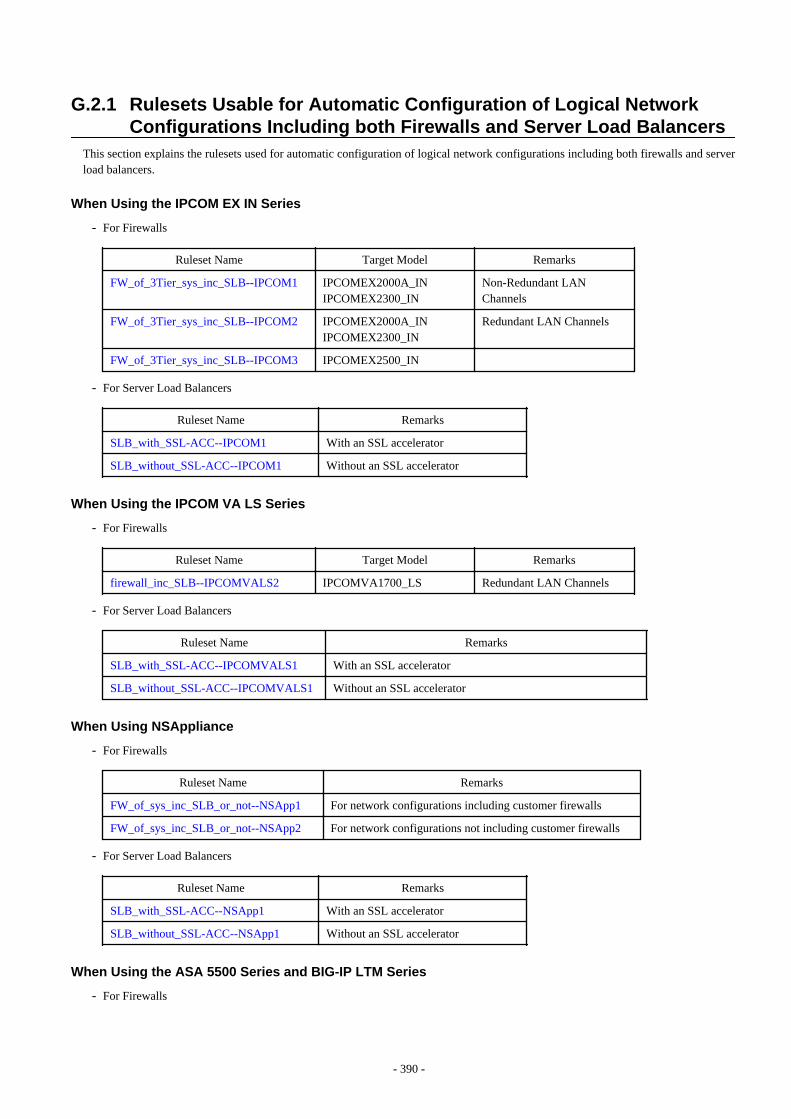
G.2.1 Rulesets Usable for Automatic Configuration of Logical NetworkConfigurations Including both Firewalls and Server Load Balancers
This section explains the rulesets used for automatic configuration of logical network configurations including both firewalls and serverload balancers.
When Using the IPCOM EX IN Series
- For Firewalls
Ruleset Name Target Model Remarks
FW_of_3Tier_sys_inc_SLB--IPCOM1 IPCOMEX2000A_INIPCOMEX2300_IN
Non-Redundant LANChannels
FW_of_3Tier_sys_inc_SLB--IPCOM2 IPCOMEX2000A_INIPCOMEX2300_IN
Redundant LAN Channels
FW_of_3Tier_sys_inc_SLB--IPCOM3 IPCOMEX2500_IN
- For Server Load Balancers
Ruleset Name Remarks
SLB_with_SSL-ACC--IPCOM1 With an SSL accelerator
SLB_without_SSL-ACC--IPCOM1 Without an SSL accelerator
When Using the IPCOM VA LS Series
- For Firewalls
Ruleset Name Target Model Remarks
firewall_inc_SLB--IPCOMVALS2 IPCOMVA1700_LS Redundant LAN Channels
- For Server Load Balancers
Ruleset Name Remarks
SLB_with_SSL-ACC--IPCOMVALS1 With an SSL accelerator
SLB_without_SSL-ACC--IPCOMVALS1 Without an SSL accelerator
When Using NSAppliance
- For Firewalls
Ruleset Name Remarks
FW_of_sys_inc_SLB_or_not--NSApp1 For network configurations including customer firewalls
FW_of_sys_inc_SLB_or_not--NSApp2 For network configurations not including customer firewalls
- For Server Load Balancers
Ruleset Name Remarks
SLB_with_SSL-ACC--NSApp1 With an SSL accelerator
SLB_without_SSL-ACC--NSApp1 Without an SSL accelerator
When Using the ASA 5500 Series and BIG-IP LTM Series
- For Firewalls
- 390 -
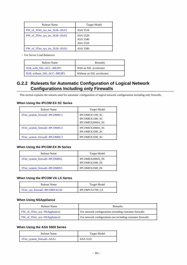
Ruleset Name Target Model
FW_of_3Tier_sys_inc_SLB--ASA1 ASA 5510
FW_of_3Tier_sys_inc_SLB--ASA2 ASA 5520ASA 5540ASA 5550
FW_of_3Tier_sys_inc_SLB--ASA3 ASA 5580
- For Server Load Balancers
Ruleset Name Remarks
SLB_with_SSL-ACC--BIGIP1 With an SSL accelerator
SLB_without_SSL-ACC--BIGIP1 Without an SSL accelerator
G.2.2 Rulesets for Automatic Configuration of Logical NetworkConfigurations Including only Firewalls
This section explains the rulesets used for automatic configuration of logical network configurations including only firewalls.
When Using the IPCOM EX SC Series
Ruleset Name Target Model
3Tier_system_firewall--IPCOMSC1 IPCOMEX1100_SCIPCOMEX1300_SCIPCOMEX2000A_SC
3Tier_system_firewall--IPCOMSC2 IPCOMEX2000A_SCIPCOMEX2300_SC
3Tier_system_firewall--IPCOMSC3 IPCOMEX2500_SC
When Using the IPCOM EX IN Series
Ruleset Name Target Model
3Tier_system_firewall--IPCOMIN2 IPCOMEX2000A_INIPCOMEX2300_IN
3Tier_system_firewall--IPCOMIN3 IPCOMEX2500_IN
When Using the IPCOM VA LS Series
Ruleset Name Target Model
3Tier_sys_firewall--IPCOMVALS2 IPCOMVA1700_LS
When Using NSAppliance
Ruleset Name Remarks
FW_of_3Tier_sys--NSAppliance1 For network configurations including customer firewalls
FW_of_3Tier_sys--NSAppliance2 For network configurations not including customer firewalls
When Using the ASA 5500 Series
Ruleset Name Target Model
3Tier_system_firewall--ASA1 ASA 5510
- 391 -
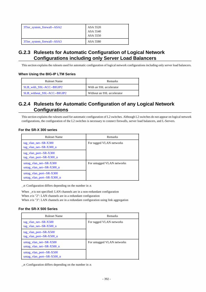
3Tier_system_firewall--ASA2 ASA 5520ASA 5540ASA 5550
3Tier_system_firewall--ASA3 ASA 5580
G.2.3 Rulesets for Automatic Configuration of Logical NetworkConfigurations including only Server Load Balancers
This section explains the rulesets used for automatic configuration of logical network configurations including only server load balancers.
When Using the BIG-IP LTM Series
Ruleset Name Remarks
SLB_with_SSL-ACC--BIGIP2 With an SSL accelerator
SLB_without_SSL-ACC--BIGIP2 Without an SSL accelerator
G.2.4 Rulesets for Automatic Configuration of any Logical NetworkConfigurations
This section explains the rulesets used for automatic configuration of L2 switches. Although L2 switches do not appear on logical networkconfigurations, the configuration of the L2 switches is necessary to connect firewalls, server load balancers, and L-Servers.
For the SR-X 300 series
Ruleset Name Remarks
tag_vlan_net--SR-X300tag_vlan_net--SR-X300_n
For tagged VLAN networks
tag_vlan_port--SR-X300tag_vlan_port--SR-X300_n
untag_vlan_net--SR-X300untag_vlan_net--SR-X300_n
For untagged VLAN networks
untag_vlan_port--SR-X300untag_vlan_port--SR-X300_n
_n: Configuration differs depending on the number in n.
When _n is not specified: LAN channels are in a non-redundant configurationWhen n is "2": LAN channels are in a redundant configurationWhen n is "3": LAN channels are in a redundant configuration using link aggregation
For the SR-X 500 Series
Ruleset Name Remarks
tag_vlan_net--SR-X500tag_vlan_net--SR-X500_n
For tagged VLAN networks
tag_vlan_port--SR-X500tag_vlan_port--SR-X500_n
untag_vlan_net--SR-X500untag_vlan_net--SR-X500_n
For untagged VLAN networks
untag_vlan_port--SR-X500untag_vlan_port--SR-X500_n
_n: Configuration differs depending on the number in n.
- 392 -
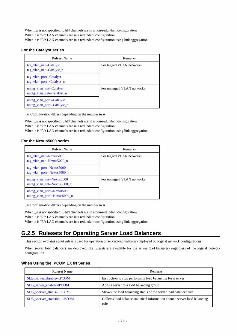
When _n is not specified: LAN channels are in a non-redundant configurationWhen n is "2": LAN channels are in a redundant configurationWhen n is "3": LAN channels are in a redundant configuration using link aggregation
For the Catalyst series
Ruleset Name Remarks
tag_vlan_net--Catalysttag_vlan_net--Catalyst_n
For tagged VLAN networks
tag_vlan_port--Catalysttag_vlan_port--Catalyst_n
untag_vlan_net--Catalystuntag_vlan_net--Catalyst_n
For untagged VLAN networks
untag_vlan_port--Catalystuntag_vlan_port--Catalyst_n
_n: Configuration differs depending on the number in n.
When _n is not specified: LAN channels are in a non-redundant configurationWhen n is "2": LAN channels are in a redundant configurationWhen n is "3": LAN channels are in a redundant configuration using link aggregation
For the Nexus5000 series
Ruleset Name Remarks
tag_vlan_net--Nexus5000tag_vlan_net--Nexus5000_n
For tagged VLAN networks
tag_vlan_port--Nexus5000tag_vlan_port--Nexus5000_n
untag_vlan_net--Nexus5000untag_vlan_net--Nexus5000_n
For untagged VLAN networks
untag_vlan_port--Nexus5000untag_vlan_port--Nexus5000_n
_n: Configuration differs depending on the number in n.
When _n is not specified: LAN channels are in a non-redundant configurationWhen n is "2": LAN channels are in a redundant configurationWhen n is "3": LAN channels are in a redundant configuration using link aggregation
G.2.5 Rulesets for Operating Server Load BalancersThis section explains about rulesets used for operation of server load balancers deployed on logical network configurations.
When server load balancers are deployed, the rulesets are available for the server load balancers regardless of the logical networkconfiguration.
When Using the IPCOM EX IN Series
Ruleset Name Remarks
SLB_server_disable--IPCOM Instruction to stop performing load balancing for a server
SLB_server_enable--IPCOM Adds a server to a load balancing group
SLB_vserver_status--IPCOM Shows the load balancing status of the server load balancer rule
SLB_vserver_statistics--IPCOM Collects load balance statistical information about a server load balancingrule
- 393 -
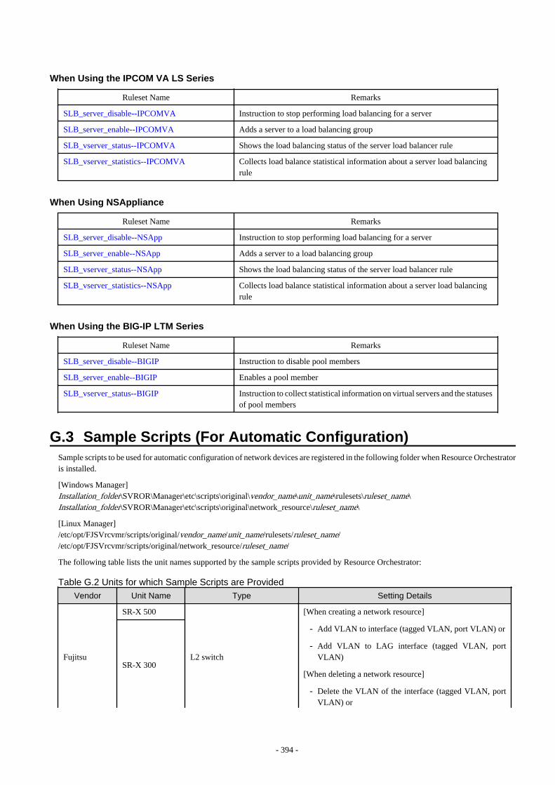
When Using the IPCOM VA LS Series
Ruleset Name Remarks
SLB_server_disable--IPCOMVA Instruction to stop performing load balancing for a server
SLB_server_enable--IPCOMVA Adds a server to a load balancing group
SLB_vserver_status--IPCOMVA Shows the load balancing status of the server load balancer rule
SLB_vserver_statistics--IPCOMVA Collects load balance statistical information about a server load balancingrule
When Using NSAppliance
Ruleset Name Remarks
SLB_server_disable--NSApp Instruction to stop performing load balancing for a server
SLB_server_enable--NSApp Adds a server to a load balancing group
SLB_vserver_status--NSApp Shows the load balancing status of the server load balancer rule
SLB_vserver_statistics--NSApp Collects load balance statistical information about a server load balancingrule
When Using the BIG-IP LTM Series
Ruleset Name Remarks
SLB_server_disable--BIGIP Instruction to disable pool members
SLB_server_enable--BIGIP Enables a pool member
SLB_vserver_status--BIGIP Instruction to collect statistical information on virtual servers and the statusesof pool members
G.3 Sample Scripts (For Automatic Configuration)Sample scripts to be used for automatic configuration of network devices are registered in the following folder when Resource Orchestratoris installed.
[Windows Manager]Installation_folder\SVROR\Manager\etc\scripts\original\vendor_name\unit_name\rulesets\ruleset_name\Installation_folder\SVROR\Manager\etc\scripts\original\network_resource\ruleset_name\
[Linux Manager]/etc/opt/FJSVrcvmr/scripts/original/vendor_name/unit_name/rulesets/ruleset_name//etc/opt/FJSVrcvmr/scripts/original/network_resource/ruleset_name/
The following table lists the unit names supported by the sample scripts provided by Resource Orchestrator:
Table G.2 Units for which Sample Scripts are Provided
Vendor Unit Name Type Setting Details
Fujitsu
SR-X 500
L2 switch
[When creating a network resource]
- Add VLAN to interface (tagged VLAN, port VLAN) or
- Add VLAN to LAG interface (tagged VLAN, portVLAN)
[When deleting a network resource]
- Delete the VLAN of the interface (tagged VLAN, portVLAN) or
SR-X 300
- 394 -
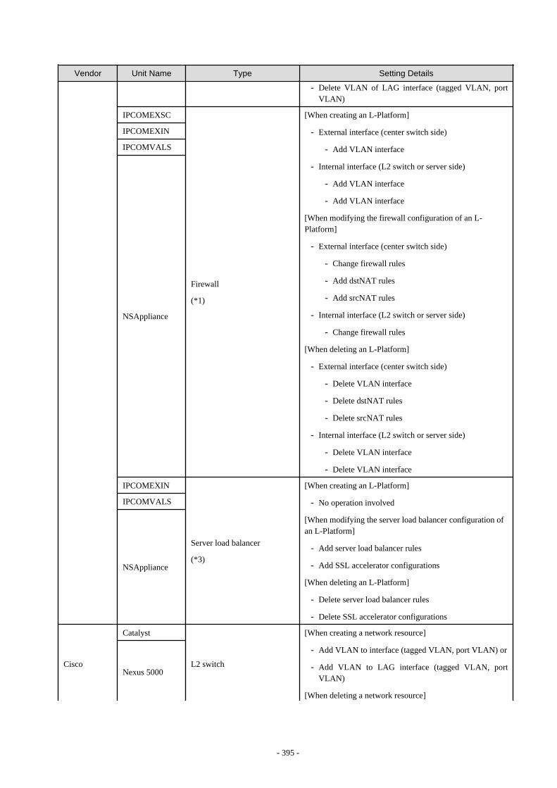
Vendor Unit Name Type Setting Details
- Delete VLAN of LAG interface (tagged VLAN, portVLAN)
IPCOMEXSC
Firewall
(*1)
[When creating an L-Platform]
- External interface (center switch side)
- Add VLAN interface
- Internal interface (L2 switch or server side)
- Add VLAN interface
- Add VLAN interface
[When modifying the firewall configuration of an L-Platform]
- External interface (center switch side)
- Change firewall rules
- Add dstNAT rules
- Add srcNAT rules
- Internal interface (L2 switch or server side)
- Change firewall rules
[When deleting an L-Platform]
- External interface (center switch side)
- Delete VLAN interface
- Delete dstNAT rules
- Delete srcNAT rules
- Internal interface (L2 switch or server side)
- Delete VLAN interface
- Delete VLAN interface
IPCOMEXIN
IPCOMVALS
NSAppliance
IPCOMEXIN
Server load balancer
(*3)
[When creating an L-Platform]
- No operation involved
[When modifying the server load balancer configuration ofan L-Platform]
- Add server load balancer rules
- Add SSL accelerator configurations
[When deleting an L-Platform]
- Delete server load balancer rules
- Delete SSL accelerator configurations
IPCOMVALS
NSAppliance
Cisco
Catalyst
L2 switch
[When creating a network resource]
- Add VLAN to interface (tagged VLAN, port VLAN) or
- Add VLAN to LAG interface (tagged VLAN, portVLAN)
[When deleting a network resource]
Nexus 5000
- 395 -
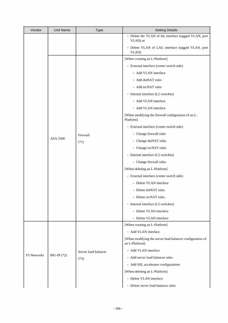
Vendor Unit Name Type Setting Details
- Delete the VLAN of the interface (tagged VLAN, portVLAN) or
- Delete VLAN of LAG interface (tagged VLAN, portVLAN)
ASA 5500Firewall
(*1)
[When creating an L-Platform]
- External interface (center switch side)
- Add VLAN interface
- Add dstNAT rules
- Add srcNAT rules
- Internal interface (L2 switches)
- Add VLAN interface
- Add VLAN interface
[When modifying the firewall configuration of an L-Platform]
- External interface (center switch side)
- Change firewall rules
- Change dstNAT rules
- Change srcNAT rules
- Internal interface (L2 switches)
- Change firewall rules
[When deleting an L-Platform]
- External interface (center switch side)
- Delete VLAN interface
- Delete dstNAT rules
- Delete srcNAT rules
- Internal interface (L2 switches)
- Delete VLAN interface
- Delete VLAN interface
F5 Networks BIG-IP (*2)Server load balancer
(*3)
[When creating an L-Platform]
- Add VLAN interface
[When modifying the server load balancer configuration ofan L-Platform]
- Add VLAN interface
- Add server load balancer rules
- Add SSL accelerator configurations
[When deleting an L-Platform]
- Delete VLAN interface
- Delete server load balancer rules
- 396 -

Vendor Unit Name Type Setting Details
- Delete SSL accelerator configurations
*1: Configure firewall rules for the VLAN interfaces of LAN ports to use as public LANs.*2: Network device names of the BIG-IP LTM series are treated as being "BIG-IP".*3: Server load balancer rules are configured for public LAN connections.
Information
When using the sample scripts provided by Resource Orchestrator, the protocols used for automatic configuration and network devicenames are as follows. Sample scripts use those protocols when connecting to network devices.
- With TELNET protocol
- SR-X 300/SR-X 500
- IPCOMEXSC/IPCOMEXIN
- IPCOMVALS
- NSAppliance
- Catalyst
- Nexus 5000
- ASA 5500
- With SSH protocol
- BIG-IP
Note
The sample scripts provided by Resource Orchestrator may be added or deleted when the software is updated.When using the sample scripts, confirm the directory on the admin server in which the sample scripts are registered beforehand.
G.3.1 Preparations for Using Sample ScriptsThis section explains the preparations for using sample scripts for automatic configuration of network devices.
- Specify "SCRIPT_EXECUTION_MODE=continue" in the definition file.For details on definition files, refer to "Definition File Name".
- For rulesets, it is necessary to register a folder created using the "Vendor" and "Unit Name" described in "Table G.2 Units for whichSample Scripts are Provided". If the necessary sample scripts are not registered in the folder, the sample scripts registered when thisproduct was installed will be copied.
- It is required to change the following files based on your system configuration.
- Parameter Files (for Scripts)
For information about parameter files, refer to "15.15 Parameter Files (for Scripts)" in the "Reference Guide (Command/XML)CE".
- Network Device Interface Configuration File
For details on how to configure the interfaces of network devices, refer to "G.5.4 Interface Configuration Files".
- It is necessary to customize the parameters of sample scripts for deploying L2 switches according to their model configuration.For information about customization, refer to the explanation of each ruleset
- 397 -
- When using the BIG-IP LTM series, it is necessary to prepare an SSH environment.Refer to "F.2.1 When Connecting to Network Devices with SSH" for more information.
G.3.2 Types of Sample ScriptsThe following sections explain the sample scripts in the following list.
- For Deploying Firewalls (IPCOM EX Series)
- For Deploying Firewalls (IPCOM VA Series)
- For Deploying Firewalls (NS Appliance)
- For Deploying Firewalls (ASA 5500 Series)
- For Deploying Firewalls and Server Load Balancers (IPCOM EX IN Series)
- For Deploying Firewalls and Server Load Balancers (IPCOM VA LS Series)
- For Deploying Firewalls and Server Load Balancers (NS Appliance)
- For Deploying Firewalls or Server Load Balancers (Combinations of ASA 5500 Series and BIG-IP LTM Series)
- For Deploying Server Load Balancers (BIG-IP LTM Series)
- For Deploying L2 Switches
G.3.3 For Deploying Firewalls (IPCOM EX Series)The default model configuration assumed by a sample script is given below:
- 398 -
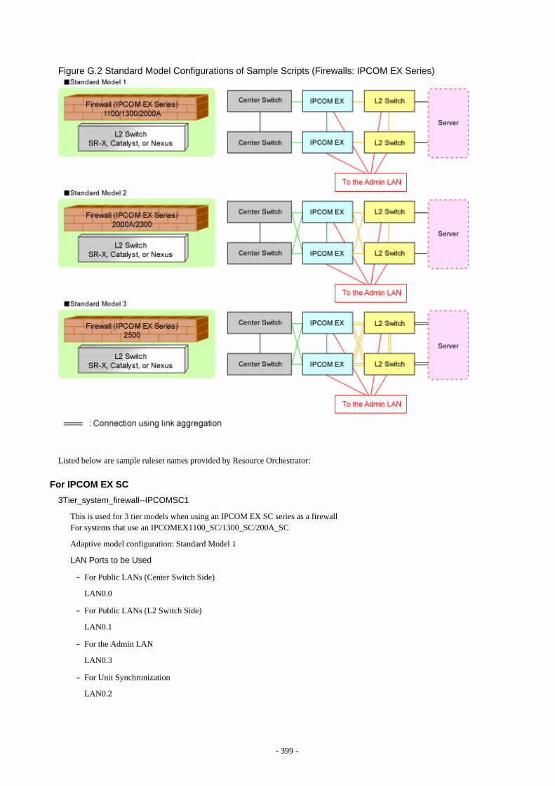
Figure G.2 Standard Model Configurations of Sample Scripts (Firewalls: IPCOM EX Series)
Listed below are sample ruleset names provided by Resource Orchestrator:
For IPCOM EX SC
3Tier_system_firewall--IPCOMSC1
This is used for 3 tier models when using an IPCOM EX SC series as a firewallFor systems that use an IPCOMEX1100_SC/1300_SC/200A_SC
Adaptive model configuration: Standard Model 1
LAN Ports to be Used
- For Public LANs (Center Switch Side)
LAN0.0
- For Public LANs (L2 Switch Side)
LAN0.1
- For the Admin LAN
LAN0.3
- For Unit Synchronization
LAN0.2
- 399 -
3Tier_system_firewall--IPCOMSC2
This is used for 3 tier models when using an IPCOM EX SC series as a firewallFor systems that use an IPCOMEX2000A_SC/2300_SC
Adaptive model configuration: Standard Model 2
LAN Ports to be Used
- For Public LANs (Center Switch Side)
bnd0: Redundant LAN Channels
- LAN0.0
- LAN1.0
- For Public LANs (L2 Switch Side)
bnd1: Redundant LAN Channels
- LAN0.1
- LAN1.1
- For the Admin LAN
LAN0.3
- For Unit Synchronization
LAN1.3
3Tier_system_firewall--IPCOMSC3
This is used for 3 tier models when using an IPCOM EX SC series as a firewallFor systems that use an IPCOMEX2500_SC
Adaptive model configuration: Standard Model 3
LAN Ports to be Used
- For Public LANs (Center Switch Side)
bnd0: Redundant LAN Channels
- LAN0.0
- LAN1.0
- For Public LANs (L2 Switch Side)
bnd1: Redundant LAN Channels
- LAN0.1 and LAN0.2
- LAN1.1 and LAN1.2
Connection using Link aggregation
- For the Admin LAN
LAN0.3
- For Unit Synchronization
LAN1.3
For IPCOM EX IN
3Tier_system_firewall--IPCOMIN2
This is used for 3 tier models when using an IPCOM EX IN series as a firewallFor systems that use an IPCOMEX2000A_IN/2300_IN
- 400 -
Adaptive model configuration: Standard Model 2
LAN Ports to be Used
- For Public LANs (Center Switch Side)
bnd0: Redundant LAN Channels
- LAN0.0
- LAN1.0
- For Public LANs (L2 Switch Side)
bnd1: Redundant LAN Channels
- LAN0.1
- LAN1.1
- For the Admin LAN
LAN0.3
- For Unit Synchronization
LAN1.3
3Tier_system_firewall--IPCOMIN3
This is used for 3 tier models when using an IPCOM EX IN series as a firewallFor systems that use an IPCOMEX2500_IN
Adaptive model configuration: Standard Model 3
LAN Ports to be Used
- For Public LANs (Center Switch Side)
bnd0: Redundant LAN Channels
- LAN0.0
- LAN1.0
- For Public LANs (L2 Switch Side)
bnd1: Redundant LAN Channels
- LAN0.1 and LAN0.2
- LAN1.1 and LAN1.2
Connection using Link aggregation
- For the Admin LAN
LAN0.3
- For Unit Synchronization
LAN1.3
G.3.4 For Deploying Firewalls (IPCOM VA Series)The default model configuration assumed by a sample script is given below:
- 401 -
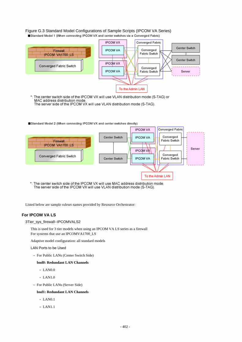
Figure G.3 Standard Model Configurations of Sample Scripts (IPCOM VA Series)
Listed below are sample ruleset names provided by Resource Orchestrator:
For IPCOM VA LS
3Tier_sys_firewall--IPCOMVALS2
This is used for 3 tier models when using an IPCOM VA LS series as a firewallFor systems that use an IPCOMVA1700_LS
Adaptive model configuration: all standard models
LAN Ports to be Used
- For Public LANs (Center Switch Side)
bnd0: Redundant LAN Channels
- LAN0.0
- LAN1.0
- For Public LANs (Server Side)
bnd1: Redundant LAN Channels
- LAN0.1
- LAN1.1
- 402 -
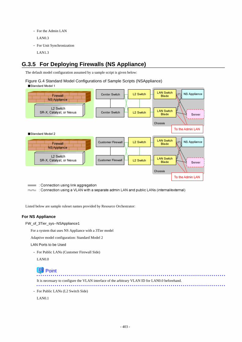
- For the Admin LAN
LAN0.3
- For Unit Synchronization
LAN1.3
G.3.5 For Deploying Firewalls (NS Appliance)The default model configuration assumed by a sample script is given below:
Figure G.4 Standard Model Configurations of Sample Scripts (NSAppliance)
Listed below are sample ruleset names provided by Resource Orchestrator:
For NS Appliance
FW_of_3Tier_sys--NSAppliance1
For a system that uses NS Appliance with a 3Tier model
Adaptive model configuration: Standard Model 2
LAN Ports to be Used
- For Public LANs (Customer Firewall Side)
LAN0.0
Point
It is necessary to configure the VLAN interface of the arbitrary VLAN ID for LAN0.0 beforehand.
- For Public LANs (L2 Switch Side)
LAN0.1
- 403 -
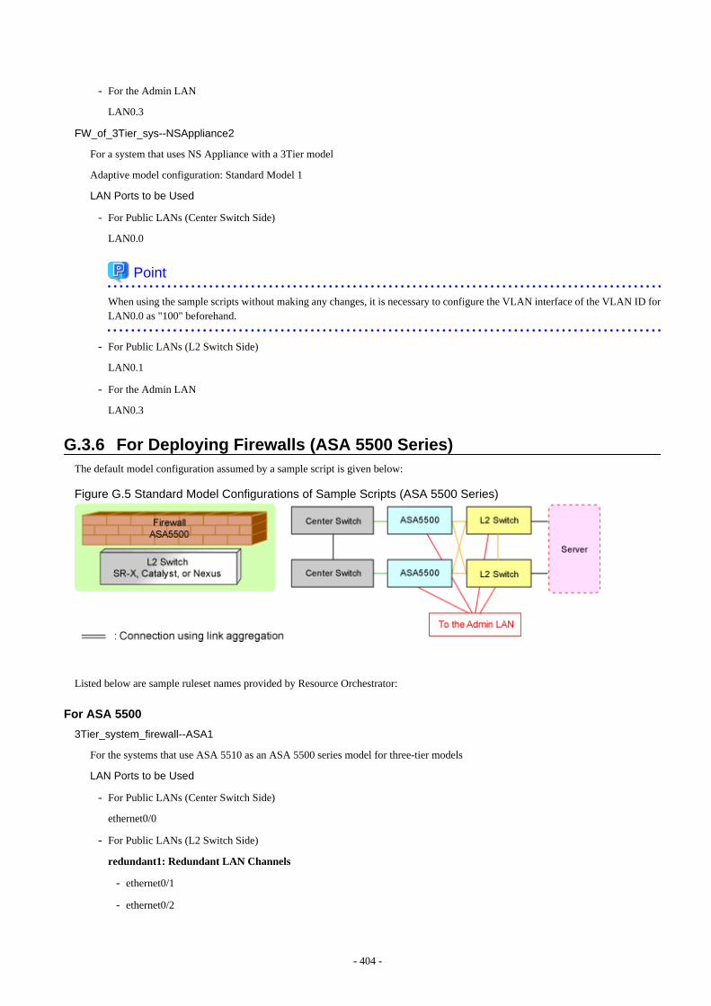
- For the Admin LAN
LAN0.3
FW_of_3Tier_sys--NSAppliance2
For a system that uses NS Appliance with a 3Tier model
Adaptive model configuration: Standard Model 1
LAN Ports to be Used
- For Public LANs (Center Switch Side)
LAN0.0
Point
When using the sample scripts without making any changes, it is necessary to configure the VLAN interface of the VLAN ID forLAN0.0 as "100" beforehand.
- For Public LANs (L2 Switch Side)
LAN0.1
- For the Admin LAN
LAN0.3
G.3.6 For Deploying Firewalls (ASA 5500 Series)The default model configuration assumed by a sample script is given below:
Figure G.5 Standard Model Configurations of Sample Scripts (ASA 5500 Series)
Listed below are sample ruleset names provided by Resource Orchestrator:
For ASA 5500
3Tier_system_firewall--ASA1
For the systems that use ASA 5510 as an ASA 5500 series model for three-tier models
LAN Ports to be Used
- For Public LANs (Center Switch Side)
ethernet0/0
- For Public LANs (L2 Switch Side)
redundant1: Redundant LAN Channels
- ethernet0/1
- ethernet0/2
- 404 -
- For the Admin LAN
management0/0
- For Unit Synchronization
ethernet0/3
3Tier_system_firewall--ASA2
For the systems that use ASA 5520/5540/5550 as an ASA 5500 series model for three-tier models
LAN Ports to be Used
- For Public LANs (Center Switch Side)
gigabitethernet0/0
- For Public LANs (L2 Switch Side)
redundant1: Redundant LAN Channels
- gigabitethernet0/1
- gigabitethernet0/2
- For the Admin LAN
management0/0
- For Unit Synchronization
gigabitethernet0/3
3Tier_system_firewall--ASA3
For the systems that use ASA 5580 as an ASA 5500 series model for three-tier models
LAN Ports to be Used
- For Public LANs (Center Switch Side)
gigabitethernet3/0
- For Public LANs (L2 Switch Side)
redundant1: Redundant LAN Channels
- gigabitethernet3/1
- gigabitethernet3/2
- For the Admin LAN
management0/0
- For Unit Synchronization
gigabitethernet3/3
G.3.7 For Deploying Firewalls and Server Load Balancers (IPCOM EX INSeries)
The default model configuration assumed by a sample script is given below:
- 405 -
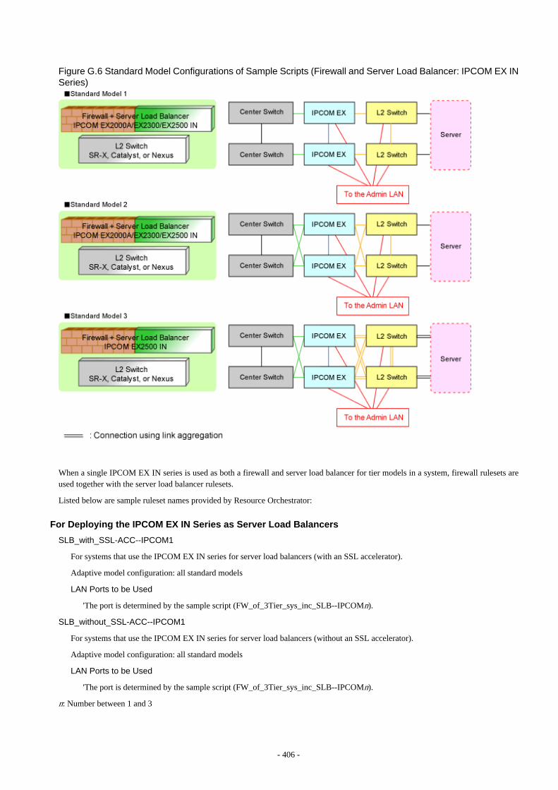
Figure G.6 Standard Model Configurations of Sample Scripts (Firewall and Server Load Balancer: IPCOM EX INSeries)
When a single IPCOM EX IN series is used as both a firewall and server load balancer for tier models in a system, firewall rulesets areused together with the server load balancer rulesets.
Listed below are sample ruleset names provided by Resource Orchestrator:
For Deploying the IPCOM EX IN Series as Server Load Balancers
SLB_with_SSL-ACC--IPCOM1
For systems that use the IPCOM EX IN series for server load balancers (with an SSL accelerator).
Adaptive model configuration: all standard models
LAN Ports to be Used
'The port is determined by the sample script (FW_of_3Tier_sys_inc_SLB--IPCOMn).
SLB_without_SSL-ACC--IPCOM1
For systems that use the IPCOM EX IN series for server load balancers (without an SSL accelerator).
Adaptive model configuration: all standard models
LAN Ports to be Used
'The port is determined by the sample script (FW_of_3Tier_sys_inc_SLB--IPCOMn).
n: Number between 1 and 3
- 406 -
For deploying the IPCOM EX IN series as firewalls
FW_of_3Tier_sys_inc_SLB--IPCOM1
For the systems that use IPCOMEX2000A_IN/2300_IN (Non-Redundant LAN Channels).
Adaptive model configuration: Standard Model 1
LAN Ports to be Used
- For Public LANs (Center Switch Side)
LAN0.0
- For Public LANs (L2 Switch Side)
LAN0.1
- For the Admin LAN
LAN0.3
- For Unit Synchronization
LAN0.2
FW_of_3Tier_sys_inc_SLB--IPCOM2
For the systems that use IPCOMEX2000A_IN/2300_IN Redundant LAN Channels).
Adaptive model configuration: Standard Model 2
LAN Ports to be Used
- For Public LANs (Center Switch Side)
bnd0: Redundant LAN Channels
- LAN0.0
- LAN1.0
- For Public LANs (L2 Switch Side)
bnd1: Redundant LAN Channels
- LAN0.1
- LAN1.1
- For the Admin LAN
LAN0.3
- For Unit Synchronization
LAN1.3
FW_of_3Tier_sys_inc_SLB--IPCOM3
For systems that use an IPCOMEX2500_IN
Adaptive model configuration: Standard Model 3
LAN Ports to be Used
- For Public LANs (Center Switch Side)
bnd0: Redundant LAN Channels
- LAN0.0
- LAN1.0
- 407 -
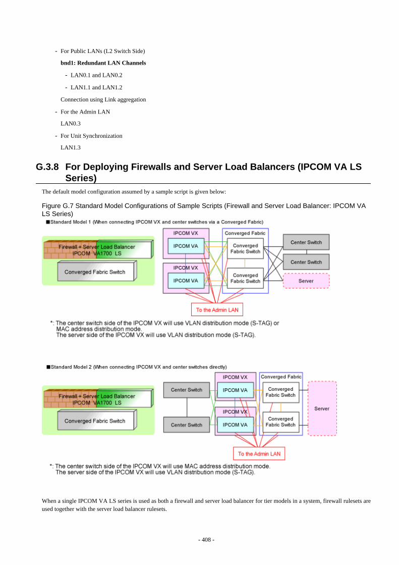
- For Public LANs (L2 Switch Side)
bnd1: Redundant LAN Channels
- LAN0.1 and LAN0.2
- LAN1.1 and LAN1.2
Connection using Link aggregation
- For the Admin LAN
LAN0.3
- For Unit Synchronization
LAN1.3
G.3.8 For Deploying Firewalls and Server Load Balancers (IPCOM VA LSSeries)
The default model configuration assumed by a sample script is given below:
Figure G.7 Standard Model Configurations of Sample Scripts (Firewall and Server Load Balancer: IPCOM VALS Series)
When a single IPCOM VA LS series is used as both a firewall and server load balancer for tier models in a system, firewall rulesets areused together with the server load balancer rulesets.
- 408 -
Listed below are sample ruleset names provided by Resource Orchestrator:
For deploying the IPCOM VA LS series as server load balancers
SLB_with_SSL-ACC--IPCOMVALS1
For systems that use the IPCOM VA LS series for server load balancers (with an SSL accelerator)
Adaptive model configuration: all standard models
LAN Ports to be Used
The port is determined by the sample script (firewall_inc_SLB--IPCOMVALS2).
SLB_without_SSL-ACC--IPCOMVALS1
For systems that use the IPCOM VA LS series for server load balancers (without an SSL accelerator)
Adaptive model configuration: all standard models
LAN Ports to be Used
The port is determined by the sample script (firewall_inc_SLB--IPCOMVALS2).
For deploying the IPCOM VA LS series as firewalls
firewall_inc_SLB--IPCOMVALS2
For the systems that use IPCOMVA1700LS (Redundant LAN Channels)
Adaptive model configuration: all standard models
LAN Ports to be Used
- For Public LANs (Center Switch Side)
bnd0: Redundant LAN Channels
- LAN0.0
- LAN1.0
- For Public LANs (Server Side)
bnd1: Redundant LAN Channels
- LAN0.1
- LAN1.1
- For the Admin LAN
LAN0.3
- For Unit Synchronization
LAN1.3
G.3.9 For Deploying Firewalls and Server Load Balancers (NS Appliance)The default model configuration assumed by a sample script is given below:
- 409 -

Figure G.8 Standard Model Configurations of Sample Scripts (Firewall and Server Load Balancer: NS Appliance)
When a single NS appliance is used as both a firewall and server load balancer for tier models in a system, firewall rulesets are usedtogether with the server load balancer rulesets.
Listed below are sample ruleset names provided by Resource Orchestrator:
For deploying NS Appliances as server load balancers
SLB_with_SSL-ACC--NSApp1
For systems that use NS appliances as server load balancers (with an SSL accelerator)
Adaptive model configuration: all standard models
LAN Ports to be Used
The port is determined by the sample script (FW_of_sys_inc_SLB_or_not--NSAppn).
SLB_without_SSL-ACC--NSApp1
For systems that use NS appliances for server load balancers (without an SSL accelerator).
Adaptive model configuration: all standard models
LAN Ports to be Used
The port is determined by the sample script (FW_of_sys_inc_SLB_or_not--NSAppn).
n: Number between 1 and 2
For deploying NS Appliances as firewalls
FW_of_sys_inc_SLB_or_not--NSApp1
For a system that uses NS appliance as a firewall with a three-tier model
Adaptive model configuration: Standard Model 2
LAN Ports to be Used
- 410 -
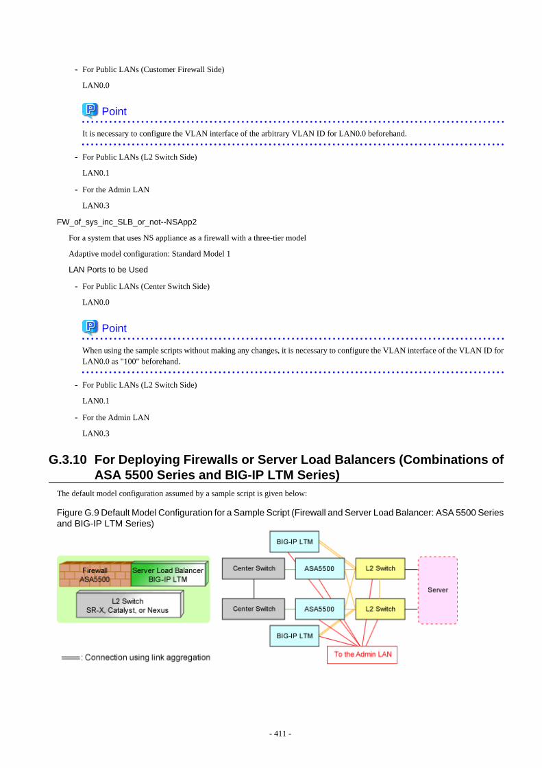
- For Public LANs (Customer Firewall Side)
LAN0.0
Point
It is necessary to configure the VLAN interface of the arbitrary VLAN ID for LAN0.0 beforehand.
- For Public LANs (L2 Switch Side)
LAN0.1
- For the Admin LAN
LAN0.3
FW_of_sys_inc_SLB_or_not--NSApp2
For a system that uses NS appliance as a firewall with a three-tier model
Adaptive model configuration: Standard Model 1
LAN Ports to be Used
- For Public LANs (Center Switch Side)
LAN0.0
Point
When using the sample scripts without making any changes, it is necessary to configure the VLAN interface of the VLAN ID forLAN0.0 as "100" beforehand.
- For Public LANs (L2 Switch Side)
LAN0.1
- For the Admin LAN
LAN0.3
G.3.10 For Deploying Firewalls or Server Load Balancers (Combinations ofASA 5500 Series and BIG-IP LTM Series)
The default model configuration assumed by a sample script is given below:
Figure G.9 Default Model Configuration for a Sample Script (Firewall and Server Load Balancer: ASA 5500 Seriesand BIG-IP LTM Series)
- 411 -
When a combination of ASA 5500 series and BIG-IP LTM series are used as the firewall and server load balancer for tier models in asystem, the firewall rulesets are used together with the server load balancer rulesets.
Listed below are sample ruleset names provided by Resource Orchestrator:
For deploying the BIG-IP LTM series as server load balancers
SLB_with_SSL-ACC--BIGIP1
For systems that use the BIG-IP LTM series as server load balancers (with an SSL accelerator)
LAN Ports to be Used
- For Public LANs and Unit Synchronization
mytrunk: Connection using Link aggregation
- 1.1
- 1.2
- For the Admin LAN
mgmt
SLB_without_SSL-ACC--BIGIP1
For systems that use the BIG-IP LTM series for server load balancers (without SSL accelerator).
LAN Ports to be Used
- For Public LANs and Unit Synchronization
mytrunk: Connection using Link aggregation
- 1.1
- 1.2
- For the Admin LAN
mgmt
For Deploying the ASA 5500 Series as Firewalls (for ASA 5500)
FW_of_3Tier_sys_inc_SLB--ASA1
For the systems that use ASA 5510 as an ASA 5500 series model for three-tier models
LAN Ports to be Used
- For Public LANs (Center Switch Side)
ethernet0/0
- For Public LANs (L2 Switch Side)
redundant1: Redundant LAN Channels
- ethernet0/1
- ethernet0/2
- For the Admin LAN
management0/0
- For Unit Synchronization
ethernet0/3
FW_of_3Tier_sys_inc_SLB--ASA2
For the systems that use ASA 5520/5540/5550 as an ASA 5500 series model for three-tier models
- 412 -

LAN Ports to be Used
- For Public LANs (Center Switch Side)
gigabitethernet0/0
- For Public LANs (L2 Switch Side)
redundant1: Redundant LAN Channels
- gigabitethernet0/1
- gigabitethernet0/2
- For the Admin LAN
management0/0
- For Unit Synchronization
gigabitethernet0/3
FW_of_3Tier_sys_inc_SLB--ASA3
For the systems that use ASA 5580 as an ASA 5500 series model for three-tier models
LAN Ports to be Used
- For Public LANs (Center Switch Side)
gigabitethernet3/0
- For Public LANs (L2 Switch Side)
redundant1: Redundant LAN Channels
- gigabitethernet3/1
- gigabitethernet3/2
- For the Admin LAN
management0/0
- For Unit Synchronization
gigabitethernet3/3
G.3.11 For Deploying Server Load Balancers (BIG-IP LTM Series)The default model configuration assumed by a sample script is given below:
Figure G.10 Standard Model Configurations of Sample Scripts (Server Load Balancers:BIG-IP LTM Series)
Listed below are sample ruleset names provided by Resource Orchestrator:
- 413 -
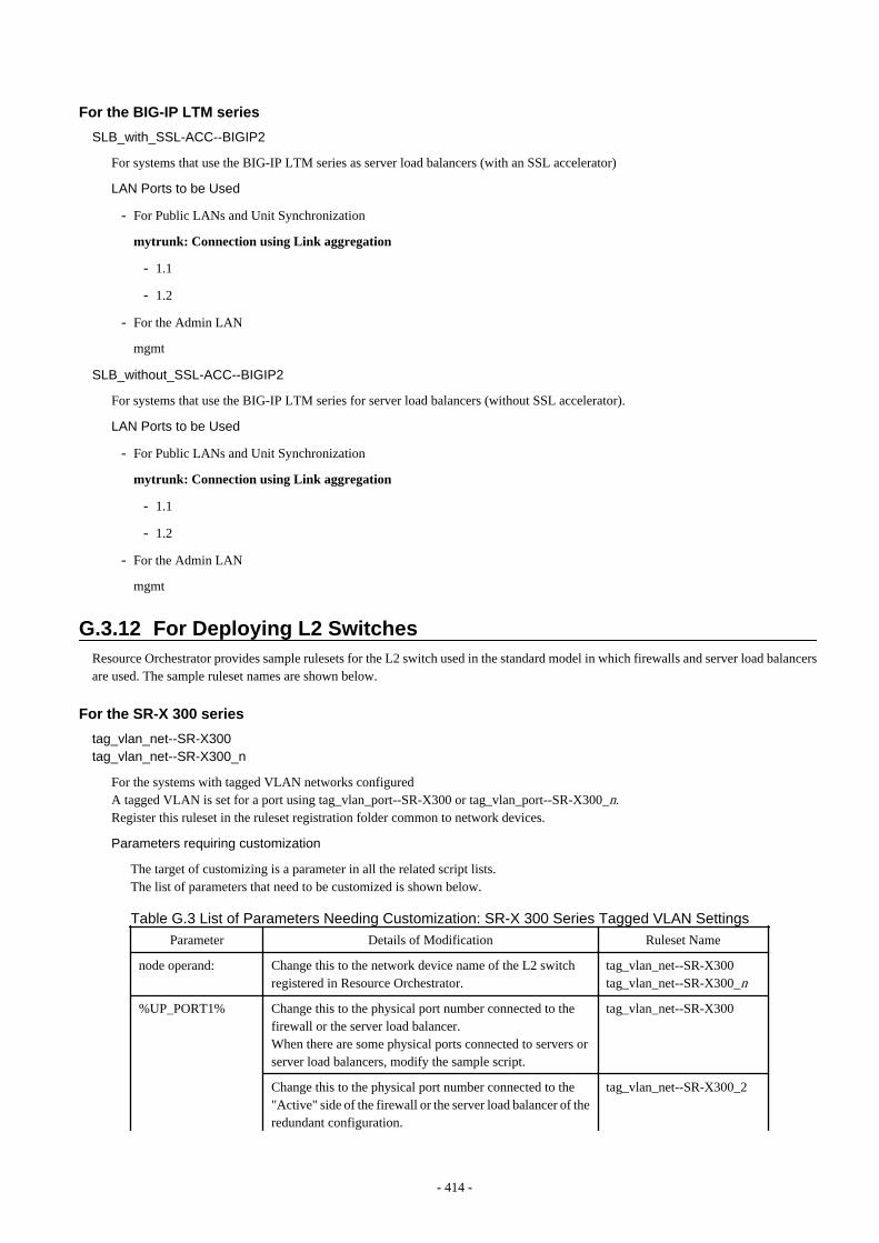
For the BIG-IP LTM series
SLB_with_SSL-ACC--BIGIP2
For systems that use the BIG-IP LTM series as server load balancers (with an SSL accelerator)
LAN Ports to be Used
- For Public LANs and Unit Synchronization
mytrunk: Connection using Link aggregation
- 1.1
- 1.2
- For the Admin LAN
mgmt
SLB_without_SSL-ACC--BIGIP2
For systems that use the BIG-IP LTM series for server load balancers (without SSL accelerator).
LAN Ports to be Used
- For Public LANs and Unit Synchronization
mytrunk: Connection using Link aggregation
- 1.1
- 1.2
- For the Admin LAN
mgmt
G.3.12 For Deploying L2 SwitchesResource Orchestrator provides sample rulesets for the L2 switch used in the standard model in which firewalls and server load balancersare used. The sample ruleset names are shown below.
For the SR-X 300 series
tag_vlan_net--SR-X300tag_vlan_net--SR-X300_n
For the systems with tagged VLAN networks configuredA tagged VLAN is set for a port using tag_vlan_port--SR-X300 or tag_vlan_port--SR-X300_n.Register this ruleset in the ruleset registration folder common to network devices.
Parameters requiring customization
The target of customizing is a parameter in all the related script lists.The list of parameters that need to be customized is shown below.
Table G.3 List of Parameters Needing Customization: SR-X 300 Series Tagged VLAN Settings
Parameter Details of Modification Ruleset Name
node operand: Change this to the network device name of the L2 switchregistered in Resource Orchestrator.
tag_vlan_net--SR-X300tag_vlan_net--SR-X300_n
%UP_PORT1% Change this to the physical port number connected to thefirewall or the server load balancer.When there are some physical ports connected to servers orserver load balancers, modify the sample script.
tag_vlan_net--SR-X300
Change this to the physical port number connected to the"Active" side of the firewall or the server load balancer of theredundant configuration.
tag_vlan_net--SR-X300_2
- 414 -
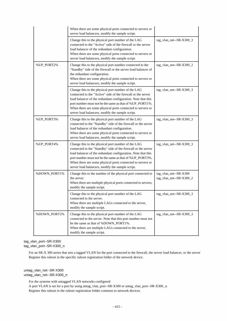
When there are some physical ports connected to servers orserver load balancers, modify the sample script.
Change this to the physical port number of the LAGconnected to the "Active" side of the firewall or the serverload balancer of the redundant configuration.When there are some physical ports connected to servers orserver load balancers, modify the sample script.
tag_vlan_net--SR-X300_3
%UP_PORT2% Change this to the physical port number connected to the"Standby" side of the firewall or the server load balancer ofthe redundant configuration.When there are some physical ports connected to servers orserver load balancers, modify the sample script.
tag_vlan_net--SR-X300_2
Change this to the physical port number of the LAGconnected to the "Active" side of the firewall or the serverload balancer of the redundant configuration. Note that thisport number must not be the same as that of %UP_PORT1%.When there are some physical ports connected to servers orserver load balancers, modify the sample script.
tag_vlan_net--SR-X300_3
%UP_PORT3% Change this to the physical port number of the LAGconnected to the "Standby" side of the firewall or the serverload balancer of the redundant configuration.When there are some physical ports connected to servers orserver load balancers, modify the sample script.
tag_vlan_net--SR-X300_3
%UP_PORT4% Change this to the physical port number of the LAGconnected to the "Standby" side of the firewall or the serverload balancer of the redundant configuration. Note that thisport number must not be the same as that of %UP_PORT3%.When there are some physical ports connected to servers orserver load balancers, modify the sample script.
tag_vlan_net--SR-X300_3
%DOWN_PORT1% Change this to the number of the physical port connected tothe server.When there are multiple physical ports connected to servers,modify the sample script.
tag_vlan_net--SR-X300tag_vlan_net--SR-X300_2
Change this to the physical port number of the LAGconnected to the server.When there are multiple LAGs connected to the server,modify the sample script.
tag_vlan_net--SR-X300_3
%DOWN_PORT2% Change this to the physical port number of the LAGconnected to the server. Note that this port number must notbe the same as that of %DOWN_PORT1%.When there are multiple LAGs connected to the server,modify the sample script.
tag_vlan_net--SR-X300_3
tag_vlan_port--SR-X300tag_vlan_port--SR-X300_n
For an SR-X 300 series that sets a tagged VLAN for the port connected to the firewall, the server load balancer, or the serverRegister this ruleset in the specific ruleset registration folder of the network device.
untag_vlan_net--SR-X300untag_vlan_net--SR-X300_n
For the systems with untagged VLAN networks configuredA port VLAN is set for a port by using untag_vlan_port--SR-X300 or untag_vlan_port--SR-X300_n.Register this ruleset in the ruleset registration folder common to network devices.
- 415 -
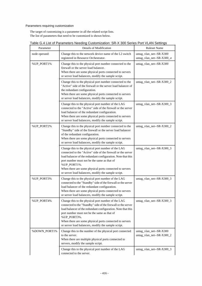
Parameters requiring customization
The target of customizing is a parameter in all the related script lists.The list of parameters that need to be customized is shown below.
Table G.4 List of Parameters Needing Customization: SR-X 300 Series Port VLAN Settings
Parameter Details of Modification Ruleset Name
node operand: Change this to the network device name of the L2 switchregistered in Resource Orchestrator.
untag_vlan_net--SR-X300untag_vlan_net--SR-X300_n
%UP_PORT1% Change this to the physical port number connected to thefirewall or the server load balancer.When there are some physical ports connected to serversor server load balancers, modify the sample script.
untag_vlan_net--SR-X300
Change this to the physical port number connected to the"Active" side of the firewall or the server load balancer ofthe redundant configuration.When there are some physical ports connected to serversor server load balancers, modify the sample script.
untag_vlan_net--SR-X300_2
Change this to the physical port number of the LAGconnected to the "Active" side of the firewall or the serverload balancer of the redundant configuration.When there are some physical ports connected to serversor server load balancers, modify the sample script.
untag_vlan_net--SR-X300_3
%UP_PORT2% Change this to the physical port number connected to the"Standby" side of the firewall or the server load balancerof the redundant configuration.When there are some physical ports connected to serversor server load balancers, modify the sample script.
untag_vlan_net--SR-X300_2
Change this to the physical port number of the LAGconnected to the "Active" side of the firewall or the serverload balancer of the redundant configuration. Note that thisport number must not be the same as that of%UP_PORT1%.When there are some physical ports connected to serversor server load balancers, modify the sample script.
untag_vlan_net--SR-X300_3
%UP_PORT3% Change this to the physical port number of the LAGconnected to the "Standby" side of the firewall or the serverload balancer of the redundant configuration.When there are some physical ports connected to serversor server load balancers, modify the sample script.
untag_vlan_net--SR-X300_3
%UP_PORT4% Change this to the physical port number of the LAGconnected to the "Standby" side of the firewall or the serverload balancer of the redundant configuration. Note that thisport number must not be the same as that of%UP_PORT3%.When there are some physical ports connected to serversor server load balancers, modify the sample script.
untag_vlan_net--SR-X300_3
%DOWN_PORT1% Change this to the number of the physical port connectedto the server.When there are multiple physical ports connected toservers, modify the sample script.
untag_vlan_net--SR-X300untag_vlan_net--SR-X300_2
Change this to the physical port number of the LAGconnected to the server.
untag_vlan_net--SR-X300_3
- 416 -
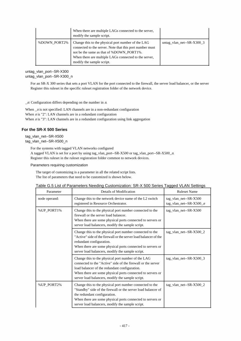
When there are multiple LAGs connected to the server,modify the sample script.
%DOWN_PORT2% Change this to the physical port number of the LAGconnected to the server. Note that this port number mustnot be the same as that of %DOWN_PORT1%.When there are multiple LAGs connected to the server,modify the sample script.
untag_vlan_net--SR-X300_3
untag_vlan_port--SR-X300untag_vlan_port--SR-X300_n
For an SR-X 300 series that sets a port VLAN for the port connected to the firewall, the server load balancer, or the serverRegister this ruleset in the specific ruleset registration folder of the network device.
_n: Configuration differs depending on the number in n.
When _n is not specified: LAN channels are in a non-redundant configurationWhen n is "2": LAN channels are in a redundant configurationWhen n is "3": LAN channels are in a redundant configuration using link aggregation
For the SR-X 500 Series
tag_vlan_net--SR-X500tag_vlan_net--SR-X500_n
For the systems with tagged VLAN networks configuredA tagged VLAN is set for a port by using tag_vlan_port--SR-X500 or tag_vlan_port--SR-X500_n.Register this ruleset in the ruleset registration folder common to network devices.
Parameters requiring customization
The target of customizing is a parameter in all the related script lists.The list of parameters that need to be customized is shown below.
Table G.5 List of Parameters Needing Customization: SR-X 500 Series Tagged VLAN Settings
Parameter Details of Modification Ruleset Name
node operand: Change this to the network device name of the L2 switchregistered in Resource Orchestrator.
tag_vlan_net--SR-X500tag_vlan_net--SR-X500_n
%UP_PORT1% Change this to the physical port number connected to thefirewall or the server load balancer.When there are some physical ports connected to servers orserver load balancers, modify the sample script.
tag_vlan_net--SR-X500
Change this to the physical port number connected to the"Active" side of the firewall or the server load balancer of theredundant configuration.When there are some physical ports connected to servers orserver load balancers, modify the sample script.
tag_vlan_net--SR-X500_2
Change this to the physical port number of the LAGconnected to the "Active" side of the firewall or the serverload balancer of the redundant configuration.When there are some physical ports connected to servers orserver load balancers, modify the sample script.
tag_vlan_net--SR-X500_3
%UP_PORT2% Change this to the physical port number connected to the"Standby" side of the firewall or the server load balancer ofthe redundant configuration.When there are some physical ports connected to servers orserver load balancers, modify the sample script.
tag_vlan_net--SR-X500_2
- 417 -
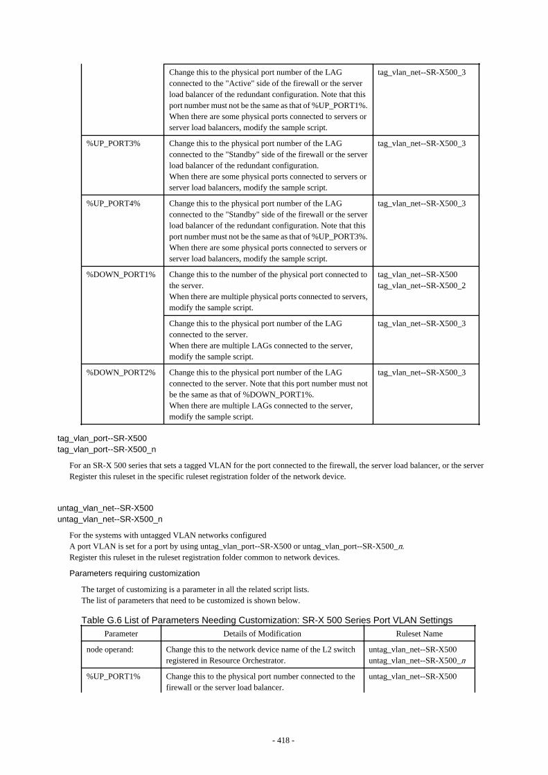
Change this to the physical port number of the LAGconnected to the "Active" side of the firewall or the serverload balancer of the redundant configuration. Note that thisport number must not be the same as that of %UP_PORT1%.When there are some physical ports connected to servers orserver load balancers, modify the sample script.
tag_vlan_net--SR-X500_3
%UP_PORT3% Change this to the physical port number of the LAGconnected to the "Standby" side of the firewall or the serverload balancer of the redundant configuration.When there are some physical ports connected to servers orserver load balancers, modify the sample script.
tag_vlan_net--SR-X500_3
%UP_PORT4% Change this to the physical port number of the LAGconnected to the "Standby" side of the firewall or the serverload balancer of the redundant configuration. Note that thisport number must not be the same as that of %UP_PORT3%.When there are some physical ports connected to servers orserver load balancers, modify the sample script.
tag_vlan_net--SR-X500_3
%DOWN_PORT1% Change this to the number of the physical port connected tothe server.When there are multiple physical ports connected to servers,modify the sample script.
tag_vlan_net--SR-X500tag_vlan_net--SR-X500_2
Change this to the physical port number of the LAGconnected to the server.When there are multiple LAGs connected to the server,modify the sample script.
tag_vlan_net--SR-X500_3
%DOWN_PORT2% Change this to the physical port number of the LAGconnected to the server. Note that this port number must notbe the same as that of %DOWN_PORT1%.When there are multiple LAGs connected to the server,modify the sample script.
tag_vlan_net--SR-X500_3
tag_vlan_port--SR-X500tag_vlan_port--SR-X500_n
For an SR-X 500 series that sets a tagged VLAN for the port connected to the firewall, the server load balancer, or the serverRegister this ruleset in the specific ruleset registration folder of the network device.
untag_vlan_net--SR-X500untag_vlan_net--SR-X500_n
For the systems with untagged VLAN networks configuredA port VLAN is set for a port by using untag_vlan_port--SR-X500 or untag_vlan_port--SR-X500_n.Register this ruleset in the ruleset registration folder common to network devices.
Parameters requiring customization
The target of customizing is a parameter in all the related script lists.The list of parameters that need to be customized is shown below.
Table G.6 List of Parameters Needing Customization: SR-X 500 Series Port VLAN Settings
Parameter Details of Modification Ruleset Name
node operand: Change this to the network device name of the L2 switchregistered in Resource Orchestrator.
untag_vlan_net--SR-X500untag_vlan_net--SR-X500_n
%UP_PORT1% Change this to the physical port number connected to thefirewall or the server load balancer.
untag_vlan_net--SR-X500
- 418 -
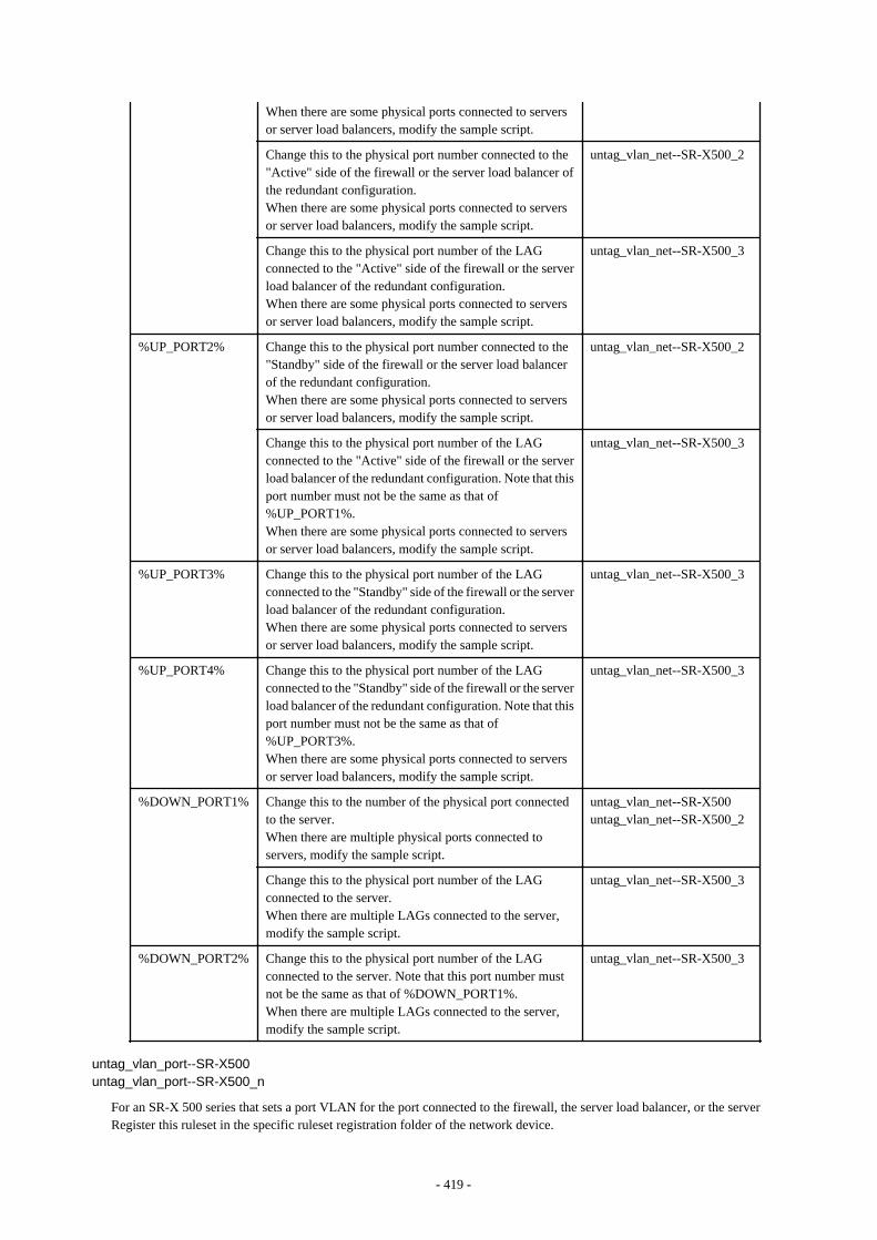
When there are some physical ports connected to serversor server load balancers, modify the sample script.
Change this to the physical port number connected to the"Active" side of the firewall or the server load balancer ofthe redundant configuration.When there are some physical ports connected to serversor server load balancers, modify the sample script.
untag_vlan_net--SR-X500_2
Change this to the physical port number of the LAGconnected to the "Active" side of the firewall or the serverload balancer of the redundant configuration.When there are some physical ports connected to serversor server load balancers, modify the sample script.
untag_vlan_net--SR-X500_3
%UP_PORT2% Change this to the physical port number connected to the"Standby" side of the firewall or the server load balancerof the redundant configuration.When there are some physical ports connected to serversor server load balancers, modify the sample script.
untag_vlan_net--SR-X500_2
Change this to the physical port number of the LAGconnected to the "Active" side of the firewall or the serverload balancer of the redundant configuration. Note that thisport number must not be the same as that of%UP_PORT1%.When there are some physical ports connected to serversor server load balancers, modify the sample script.
untag_vlan_net--SR-X500_3
%UP_PORT3% Change this to the physical port number of the LAGconnected to the "Standby" side of the firewall or the serverload balancer of the redundant configuration.When there are some physical ports connected to serversor server load balancers, modify the sample script.
untag_vlan_net--SR-X500_3
%UP_PORT4% Change this to the physical port number of the LAGconnected to the "Standby" side of the firewall or the serverload balancer of the redundant configuration. Note that thisport number must not be the same as that of%UP_PORT3%.When there are some physical ports connected to serversor server load balancers, modify the sample script.
untag_vlan_net--SR-X500_3
%DOWN_PORT1% Change this to the number of the physical port connectedto the server.When there are multiple physical ports connected toservers, modify the sample script.
untag_vlan_net--SR-X500untag_vlan_net--SR-X500_2
Change this to the physical port number of the LAGconnected to the server.When there are multiple LAGs connected to the server,modify the sample script.
untag_vlan_net--SR-X500_3
%DOWN_PORT2% Change this to the physical port number of the LAGconnected to the server. Note that this port number mustnot be the same as that of %DOWN_PORT1%.When there are multiple LAGs connected to the server,modify the sample script.
untag_vlan_net--SR-X500_3
untag_vlan_port--SR-X500untag_vlan_port--SR-X500_n
For an SR-X 500 series that sets a port VLAN for the port connected to the firewall, the server load balancer, or the serverRegister this ruleset in the specific ruleset registration folder of the network device.
- 419 -
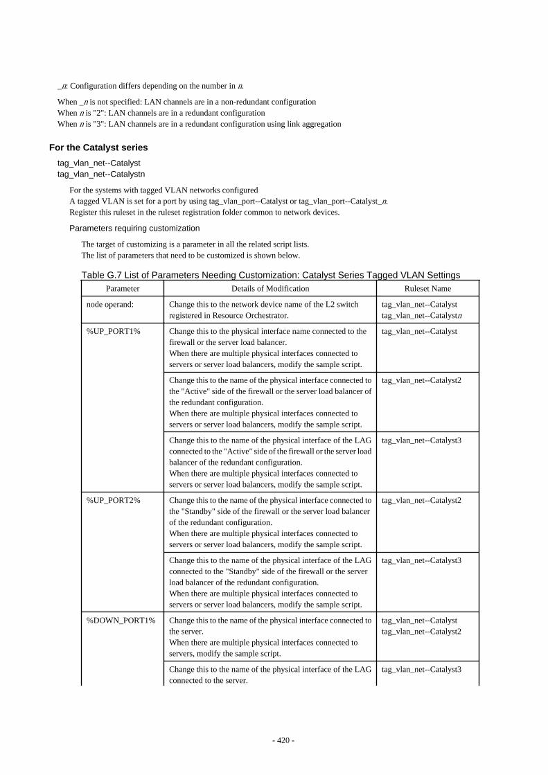
_n: Configuration differs depending on the number in n.
When _n is not specified: LAN channels are in a non-redundant configurationWhen n is "2": LAN channels are in a redundant configurationWhen n is "3": LAN channels are in a redundant configuration using link aggregation
For the Catalyst series
tag_vlan_net--Catalysttag_vlan_net--Catalystn
For the systems with tagged VLAN networks configuredA tagged VLAN is set for a port by using tag_vlan_port--Catalyst or tag_vlan_port--Catalyst_n.Register this ruleset in the ruleset registration folder common to network devices.
Parameters requiring customization
The target of customizing is a parameter in all the related script lists.The list of parameters that need to be customized is shown below.
Table G.7 List of Parameters Needing Customization: Catalyst Series Tagged VLAN Settings
Parameter Details of Modification Ruleset Name
node operand: Change this to the network device name of the L2 switchregistered in Resource Orchestrator.
tag_vlan_net--Catalysttag_vlan_net--Catalystn
%UP_PORT1% Change this to the physical interface name connected to thefirewall or the server load balancer.When there are multiple physical interfaces connected toservers or server load balancers, modify the sample script.
tag_vlan_net--Catalyst
Change this to the name of the physical interface connected tothe "Active" side of the firewall or the server load balancer ofthe redundant configuration.When there are multiple physical interfaces connected toservers or server load balancers, modify the sample script.
tag_vlan_net--Catalyst2
Change this to the name of the physical interface of the LAGconnected to the "Active" side of the firewall or the server loadbalancer of the redundant configuration.When there are multiple physical interfaces connected toservers or server load balancers, modify the sample script.
tag_vlan_net--Catalyst3
%UP_PORT2% Change this to the name of the physical interface connected tothe "Standby" side of the firewall or the server load balancerof the redundant configuration.When there are multiple physical interfaces connected toservers or server load balancers, modify the sample script.
tag_vlan_net--Catalyst2
Change this to the name of the physical interface of the LAGconnected to the "Standby" side of the firewall or the serverload balancer of the redundant configuration.When there are multiple physical interfaces connected toservers or server load balancers, modify the sample script.
tag_vlan_net--Catalyst3
%DOWN_PORT1% Change this to the name of the physical interface connected tothe server.When there are multiple physical interfaces connected toservers, modify the sample script.
tag_vlan_net--Catalysttag_vlan_net--Catalyst2
Change this to the name of the physical interface of the LAGconnected to the server.
tag_vlan_net--Catalyst3
- 420 -
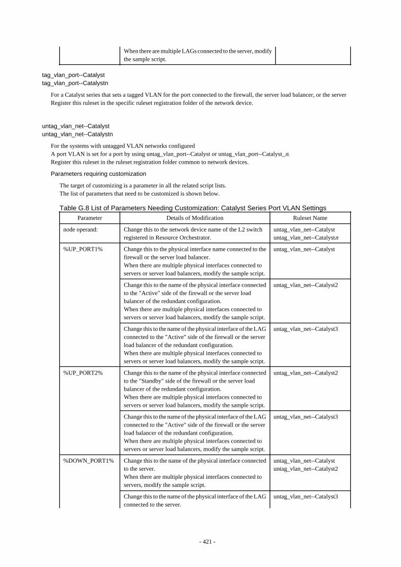
When there are multiple LAGs connected to the server, modifythe sample script.
tag_vlan_port--Catalysttag_vlan_port--Catalystn
For a Catalyst series that sets a tagged VLAN for the port connected to the firewall, the server load balancer, or the serverRegister this ruleset in the specific ruleset registration folder of the network device.
untag_vlan_net--Catalystuntag_vlan_net--Catalystn
For the systems with untagged VLAN networks configuredA port VLAN is set for a port by using untag_vlan_port--Catalyst or untag_vlan_port--Catalyst_n.Register this ruleset in the ruleset registration folder common to network devices.
Parameters requiring customization
The target of customizing is a parameter in all the related script lists.The list of parameters that need to be customized is shown below.
Table G.8 List of Parameters Needing Customization: Catalyst Series Port VLAN Settings
Parameter Details of Modification Ruleset Name
node operand: Change this to the network device name of the L2 switchregistered in Resource Orchestrator.
untag_vlan_net--Catalystuntag_vlan_net--Catalystn
%UP_PORT1% Change this to the physical interface name connected to thefirewall or the server load balancer.When there are multiple physical interfaces connected toservers or server load balancers, modify the sample script.
untag_vlan_net--Catalyst
Change this to the name of the physical interface connectedto the "Active" side of the firewall or the server loadbalancer of the redundant configuration.When there are multiple physical interfaces connected toservers or server load balancers, modify the sample script.
untag_vlan_net--Catalyst2
Change this to the name of the physical interface of the LAGconnected to the "Active" side of the firewall or the serverload balancer of the redundant configuration.When there are multiple physical interfaces connected toservers or server load balancers, modify the sample script.
untag_vlan_net--Catalyst3
%UP_PORT2% Change this to the name of the physical interface connectedto the "Standby" side of the firewall or the server loadbalancer of the redundant configuration.When there are multiple physical interfaces connected toservers or server load balancers, modify the sample script.
untag_vlan_net--Catalyst2
Change this to the name of the physical interface of the LAGconnected to the "Active" side of the firewall or the serverload balancer of the redundant configuration.When there are multiple physical interfaces connected toservers or server load balancers, modify the sample script.
untag_vlan_net--Catalyst3
%DOWN_PORT1% Change this to the name of the physical interface connectedto the server.When there are multiple physical interfaces connected toservers, modify the sample script.
untag_vlan_net--Catalystuntag_vlan_net--Catalyst2
Change this to the name of the physical interface of the LAGconnected to the server.
untag_vlan_net--Catalyst3
- 421 -
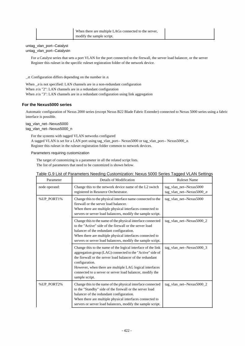
When there are multiple LAGs connected to the server,modify the sample script.
untag_vlan_port--Catalystuntag_vlan_port--Catalystn
For a Catalyst series that sets a port VLAN for the port connected to the firewall, the server load balancer, or the serverRegister this ruleset in the specific ruleset registration folder of the network device.
_n: Configuration differs depending on the number in n.
When _n is not specified: LAN channels are in a non-redundant configurationWhen n is "2": LAN channels are in a redundant configurationWhen n is "3": LAN channels are in a redundant configuration using link aggregation
For the Nexus5000 series
Automatic configuration of Nexus 2000 series (except Nexus B22 Blade Fabric Extender) connected to Nexus 5000 series using a fabricinterface is possible.
tag_vlan_net--Nexus5000tag_vlan_net--Nexus5000_n
For the systems with tagged VLAN networks configuredA tagged VLAN is set for a LAN port using tag_vlan_port-- Nexus5000 or tag_vlan_port-- Nexus5000_n.Register this ruleset in the ruleset registration folder common to network devices.
Parameters requiring customization
The target of customizing is a parameter in all the related script lists.The list of parameters that need to be customized is shown below.
Table G.9 List of Parameters Needing Customization: Nexus 5000 Series Tagged VLAN Settings
Parameter Details of Modification Ruleset Name
node operand: Change this to the network device name of the L2 switchregistered in Resource Orchestrator.
tag_vlan_net--Nexus5000tag_vlan_net--Nexus5000_n
%UP_PORT1% Change this to the physical interface name connected to thefirewall or the server load balancer.When there are multiple physical interfaces connected toservers or server load balancers, modify the sample script.
tag_vlan_net--Nexus5000
Change this to the name of the physical interface connectedto the "Active" side of the firewall or the server loadbalancer of the redundant configuration.When there are multiple physical interfaces connected toservers or server load balancers, modify the sample script.
tag_vlan_net--Nexus5000_2
Change this to the name of the logical interface of the linkaggregation group (LAG) connected to the "Active" side ofthe firewall or the server load balancer of the redundantconfiguration.However, when there are multiple LAG logical interfacesconnected to a server or server load balancer, modify thesample script.
tag_vlan_net--Nexus5000_3
%UP_PORT2% Change this to the name of the physical interface connectedto the "Standby" side of the firewall or the server loadbalancer of the redundant configuration.When there are multiple physical interfaces connected toservers or server load balancers, modify the sample script.
tag_vlan_net--Nexus5000_2
- 422 -

Change this to the name of the logical interface of the linkaggregation group (LAG) connected to the "Standby" sideof the firewall or the server load balancer of the redundantconfiguration.However, when there are multiple LAG logical interfacesconnected to a server or server load balancer, modify thesample script.
tag_vlan_net--Nexus5000_3
%DOWN_PORT1% Change this to the name of the physical interface connectedto the server.When there are multiple physical interfaces connected toservers, modify the sample script.
tag_vlan_net--Nexus5000tag_vlan_net--Nexus5000_2
Change the logical interface name of the LAG connectedto the server.When there are multiple LAG logical interfaces connectedto a server, modify the sample script.
tag_vlan_net--Nexus5000_3
When configuring a Nexus 2000 (excluding Nexus B22 Blade Fabric Extender) connected to a Nexus 5000 with fabric interface,set the physical interface name of the Nexus 2000 for the above parameter.
tag_vlan_port--Nexus5000tag_vlan_port--Nexus5000_n
For a Nexus 5000 with a tagged VLAN configured for the port connected to the firewall, server load balancer, or serverRegister this ruleset in the specific ruleset registration folder of the network device.
untag_vlan_net--Nexus5000untag_vlan_net--Nexus5000_n
For the systems with untagged VLAN networks configuredA port VLAN is set for a port using untag_vlan_port-Nexus5000 or untag_vlan_port-Nexus5000_n.Register this ruleset in the ruleset registration folder common to network devices.
Parameters requiring customization
The target of customizing is a parameter in all the related script lists.The list of parameters that need to be customized is shown below.
Table G.10 List of Parameters Needing Customization: Nexus 5000 Series Port VLAN Settings
Parameter Details of Modification Ruleset Name
node operand: Change this to the network device name of the L2 switchregistered in Resource Orchestrator.
untag_vlan_net--Nexus5000untag_vlan_net--Nexus5000_n
%UP_PORT1% Change this to the physical interface name connected tothe firewall or the server load balancer.When there are multiple physical interfaces connected toservers or server load balancers, modify the samplescript.
untag_vlan_net--Nexus5000
Change this to the name of the physical interfaceconnected to the "Active" side of the firewall or theserver load balancer of the redundant configuration.When there are multiple physical interfaces connected toservers or server load balancers, modify the samplescript.
untag_vlan_net--Nexus5000_2
Change this to the name of the logical interface of thelink aggregation group (LAG) connected to the "Active"side of the firewall or the server load balancer of theredundant configuration.However, when there are multiple LAG logical
untag_vlan_net--Nexus5000_3
- 423 -
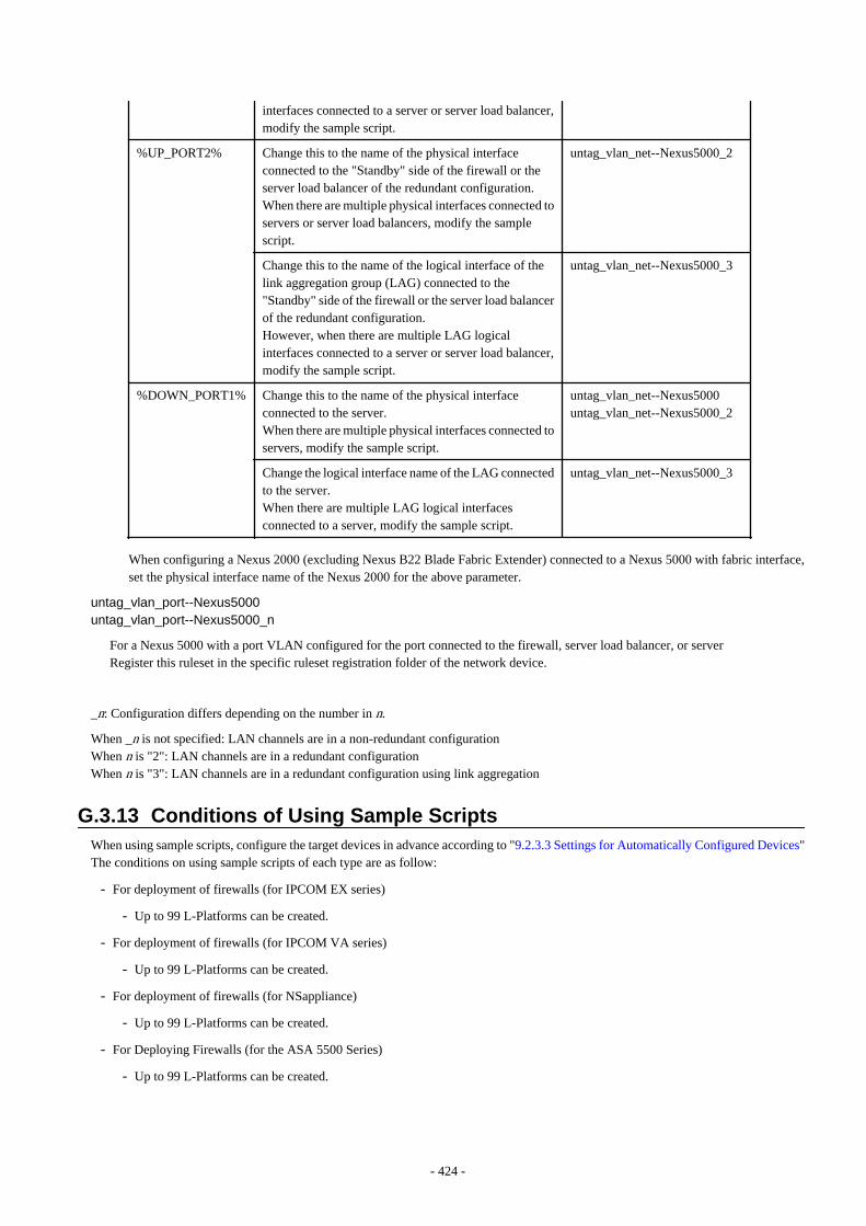
interfaces connected to a server or server load balancer,modify the sample script.
%UP_PORT2% Change this to the name of the physical interfaceconnected to the "Standby" side of the firewall or theserver load balancer of the redundant configuration.When there are multiple physical interfaces connected toservers or server load balancers, modify the samplescript.
untag_vlan_net--Nexus5000_2
Change this to the name of the logical interface of thelink aggregation group (LAG) connected to the"Standby" side of the firewall or the server load balancerof the redundant configuration.However, when there are multiple LAG logicalinterfaces connected to a server or server load balancer,modify the sample script.
untag_vlan_net--Nexus5000_3
%DOWN_PORT1% Change this to the name of the physical interfaceconnected to the server.When there are multiple physical interfaces connected toservers, modify the sample script.
untag_vlan_net--Nexus5000untag_vlan_net--Nexus5000_2
Change the logical interface name of the LAG connectedto the server.When there are multiple LAG logical interfacesconnected to a server, modify the sample script.
untag_vlan_net--Nexus5000_3
When configuring a Nexus 2000 (excluding Nexus B22 Blade Fabric Extender) connected to a Nexus 5000 with fabric interface,set the physical interface name of the Nexus 2000 for the above parameter.
untag_vlan_port--Nexus5000untag_vlan_port--Nexus5000_n
For a Nexus 5000 with a port VLAN configured for the port connected to the firewall, server load balancer, or serverRegister this ruleset in the specific ruleset registration folder of the network device.
_n: Configuration differs depending on the number in n.
When _n is not specified: LAN channels are in a non-redundant configurationWhen n is "2": LAN channels are in a redundant configurationWhen n is "3": LAN channels are in a redundant configuration using link aggregation
G.3.13 Conditions of Using Sample ScriptsWhen using sample scripts, configure the target devices in advance according to "9.2.3.3 Settings for Automatically Configured Devices"The conditions on using sample scripts of each type are as follow:
- For deployment of firewalls (for IPCOM EX series)
- Up to 99 L-Platforms can be created.
- For deployment of firewalls (for IPCOM VA series)
- Up to 99 L-Platforms can be created.
- For deployment of firewalls (for NSappliance)
- Up to 99 L-Platforms can be created.
- For Deploying Firewalls (for the ASA 5500 Series)
- Up to 99 L-Platforms can be created.
- 424 -
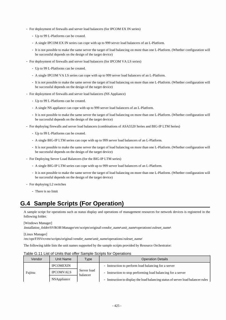
- For deployment of firewalls and server load balancers (for IPCOM EX IN series)
- Up to 99 L-Platforms can be created.
- A single IPCOM EX IN series can cope with up to 999 server load balancers of an L-Platform.
- It is not possible to make the same server the target of load balancing on more than one L-Platform. (Whether configuration willbe successful depends on the design of the target device)
- For deployment of firewalls and server load balancers (for IPCOM VA LS series)
- Up to 99 L-Platforms can be created.
- A single IPCOM VA LS series can cope with up to 999 server load balancers of an L-Platform.
- It is not possible to make the same server the target of load balancing on more than one L-Platform. (Whether configuration willbe successful depends on the design of the target device)
- For deployment of firewalls and server load balancers (NS Appliance)
- Up to 99 L-Platforms can be created.
- A single NS appliance can cope with up to 999 server load balancers of an L-Platform.
- It is not possible to make the same server the target of load balancing on more than one L-Platform. (Whether configuration willbe successful depends on the design of the target device)
- For deploying firewalls and server load balancers (combinations of ASA5520 Series and BIG-IP LTM Series)
- Up to 99 L-Platforms can be created.
- A single BIG-IP LTM series can cope with up to 999 server load balancers of an L-Platform.
- It is not possible to make the same server the target of load balancing on more than one L-Platform. (Whether configuration willbe successful depends on the design of the target device)
- For Deploying Server Load Balancers (for the BIG-IP LTM series)
- A single BIG-IP LTM series can cope with up to 999 server load balancers of an L-Platform.
- It is not possible to make the same server the target of load balancing on more than one L-Platform. (Whether configuration willbe successful depends on the design of the target device)
- For deploying L2 switches
- There is no limit
G.4 Sample Scripts (For Operation)A sample script for operations such as status display and operations of management resources for network devices is registered in thefollowing folder.
[Windows Manager]Installation_folder\SVROR\Manager\etc\scripts\original\vendor_name\unit_name\operations\ruleset_name\
[Linux Manager]/etc/opt/FJSVrcvmr/scripts/original/vendor_name/unit_name/operations/ruleset_name/
The following table lists the unit names supported by the sample scripts provided by Resource Orchestrator:
Table G.11 List of Units that offer Sample Scripts for Operations
Vendor Unit Name Type Operation Details
Fujitsu
IPCOMEXINServer loadbalancer
- Instruction to perform load balancing for a server
- Instruction to stop performing load balancing for a server
- Instruction to display the load balancing status of server load balancer rules
IPCOMVALS
NSAppliance
- 425 -

Vendor Unit Name Type Operation Details
- Instruction to collect statistical information of the load balancing status ofserver load balancer rules
F5 Networks BIG-IP (*)
- Instruction to enable pool members
- Instruction to disable pool members
- Instruction to collect statistical information on virtual servers and thestatuses of pool members
*: Device names of the BIG-IP LTM series are treated as being "BIG-IP".
Information
When using the sample scripts provided by Resource Orchestrator, the protocols used for automatic configuration and network devicenames are as follows. Sample scripts use those protocols when connecting to network devices.
- With TELNET protocol
- IPCOMEXIN
- IPCOMVALS
- NSAppliance
- With SSH protocol
- BIG-IP
Note
The sample scripts provided by Resource Orchestrator may be added or deleted when the software is updated.When using the sample scripts, confirm the directory on the admin server in which the sample scripts are registered beforehand.
G.4.1 Preparations for Using Sample ScriptsThis section explains the preparations for using sample scripts for automatic configuration of network devices.
- Make sure that "Folders for Registering Rulesets" are created.The names of these folders are "Vendor", "Unit name", and "ruleset name" of the sample scripts described in "Table G.11 List of Unitsthat offer Sample Scripts for Operations".When necessary sample scripts are not registered, copy the sample scripts registered when installing this product.
G.4.2 Prerequisites for Executing Sample Scripts for OperationsIf you execute sample scripts for operations, they must meet all of the following conditions.
- The server load balancer is deployed using the sample script provided for deploying server load balancers.
- Server load balancer rules have been configured for the server load balancer after deploying the L-Platform
- For the IPCOM EX IN series, IPCOM VA LS series, and BIG-IP LTM series of redundant configurations, devices in active status arenot set to maintenance mode
G.4.3 For Operation of Server Load BalancersThe names of sample rulesets for operations provided in this product are shown below.
- 426 -
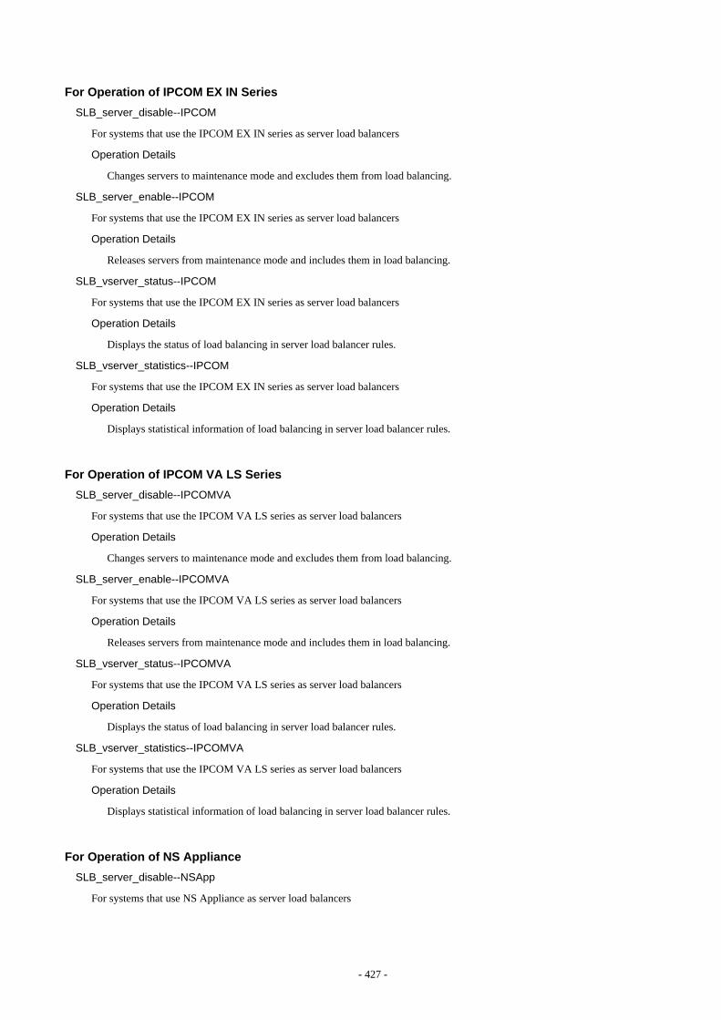
For Operation of IPCOM EX IN Series
SLB_server_disable--IPCOM
For systems that use the IPCOM EX IN series as server load balancers
Operation Details
Changes servers to maintenance mode and excludes them from load balancing.
SLB_server_enable--IPCOM
For systems that use the IPCOM EX IN series as server load balancers
Operation Details
Releases servers from maintenance mode and includes them in load balancing.
SLB_vserver_status--IPCOM
For systems that use the IPCOM EX IN series as server load balancers
Operation Details
Displays the status of load balancing in server load balancer rules.
SLB_vserver_statistics--IPCOM
For systems that use the IPCOM EX IN series as server load balancers
Operation Details
Displays statistical information of load balancing in server load balancer rules.
For Operation of IPCOM VA LS Series
SLB_server_disable--IPCOMVA
For systems that use the IPCOM VA LS series as server load balancers
Operation Details
Changes servers to maintenance mode and excludes them from load balancing.
SLB_server_enable--IPCOMVA
For systems that use the IPCOM VA LS series as server load balancers
Operation Details
Releases servers from maintenance mode and includes them in load balancing.
SLB_vserver_status--IPCOMVA
For systems that use the IPCOM VA LS series as server load balancers
Operation Details
Displays the status of load balancing in server load balancer rules.
SLB_vserver_statistics--IPCOMVA
For systems that use the IPCOM VA LS series as server load balancers
Operation Details
Displays statistical information of load balancing in server load balancer rules.
For Operation of NS Appliance
SLB_server_disable--NSApp
For systems that use NS Appliance as server load balancers
- 427 -

Operation Details
Changes servers to maintenance mode and excludes them from load balancing.
SLB_server_enable--NSApp
For systems that use NS Appliance as server load balancers
Operation Details
Releases servers from maintenance mode and includes them in load balancing.
SLB_vserver_status--NSApp
For systems that use NS Appliance as server load balancers
Operation Details
Displays the status of load balancing in server load balancer rules.
SLB_vserver_statistics--NSApp
For systems that use NS Appliance as server load balancers
Operation Details
Displays statistical information of load balancing in server load balancer rules.
For operating the BIG-IP LTM series
SLB_server_disable--BIGIP
For systems that use the BIG-IP LTM series as server load balancers
Operation Details
Changes pool member (load-balanced servers) to disable status and excludes them from load balancing.
SLB_server_enable--BIGIP
For systems that use the BIG-IP LTM series as server load balancers
Operation Details
Changes pool members (load-balanced servers) to enable status and includes them in load balancing.
SLB_vserver_status--BIGIP
For systems that use the BIG-IP LTM series as server load balancers
Operation Details
Collects statistical information of virtual servers and the statuses of pool members.
G.5 Sample Script FilesThis section describes files related to the sample scripts.
G.5.1 Script List FilesThis section describes the script list files that are provided for each ruleset.
Table G.12 List of Script List Files Provided for each Ruleset
Script List Type File Name
Script lists for setup create.lst
Script lists for setup error recovery create_recovery.lst
Script list for modification modify.lst
Script lists for modification error recovery modify_recovery.lst
- 428 -
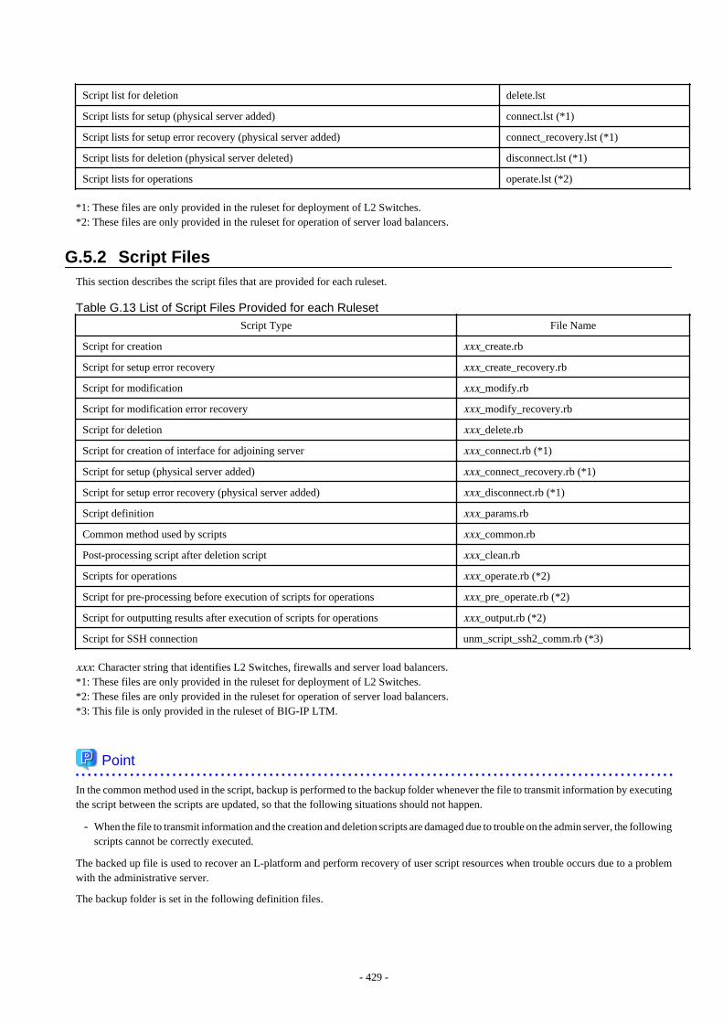
Script list for deletion delete.lst
Script lists for setup (physical server added) connect.lst (*1)
Script lists for setup error recovery (physical server added) connect_recovery.lst (*1)
Script lists for deletion (physical server deleted) disconnect.lst (*1)
Script lists for operations operate.lst (*2)
*1: These files are only provided in the ruleset for deployment of L2 Switches.*2: These files are only provided in the ruleset for operation of server load balancers.
G.5.2 Script FilesThis section describes the script files that are provided for each ruleset.
Table G.13 List of Script Files Provided for each Ruleset
Script Type File Name
Script for creation xxx_create.rb
Script for setup error recovery xxx_create_recovery.rb
Script for modification xxx_modify.rb
Script for modification error recovery xxx_modify_recovery.rb
Script for deletion xxx_delete.rb
Script for creation of interface for adjoining server xxx_connect.rb (*1)
Script for setup (physical server added) xxx_connect_recovery.rb (*1)
Script for setup error recovery (physical server added) xxx_disconnect.rb (*1)
Script definition xxx_params.rb
Common method used by scripts xxx_common.rb
Post-processing script after deletion script xxx_clean.rb
Scripts for operations xxx_operate.rb (*2)
Script for pre-processing before execution of scripts for operations xxx_pre_operate.rb (*2)
Script for outputting results after execution of scripts for operations xxx_output.rb (*2)
Script for SSH connection unm_script_ssh2_comm.rb (*3)
xxx: Character string that identifies L2 Switches, firewalls and server load balancers.*1: These files are only provided in the ruleset for deployment of L2 Switches.*2: These files are only provided in the ruleset for operation of server load balancers.*3: This file is only provided in the ruleset of BIG-IP LTM.
Point
In the common method used in the script, backup is performed to the backup folder whenever the file to transmit information by executingthe script between the scripts are updated, so that the following situations should not happen.
- When the file to transmit information and the creation and deletion scripts are damaged due to trouble on the admin server, the followingscripts cannot be correctly executed.
The backed up file is used to recover an L-platform and perform recovery of user script resources when trouble occurs due to a problemwith the administrative server.
The backup folder is set in the following definition files.
- 429 -
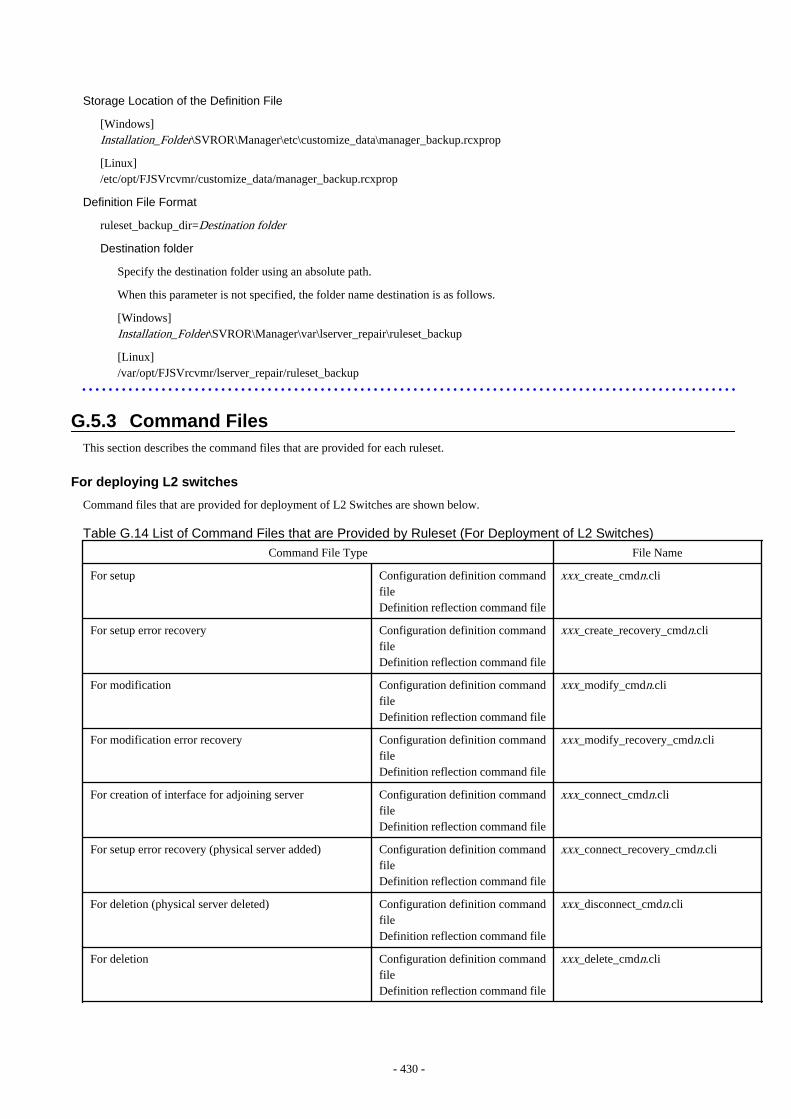
Storage Location of the Definition File
[Windows]Installation_Folder\SVROR\Manager\etc\customize_data\manager_backup.rcxprop
[Linux]/etc/opt/FJSVrcvmr/customize_data/manager_backup.rcxprop
Definition File Format
ruleset_backup_dir=Destination folder
Destination folder
Specify the destination folder using an absolute path.
When this parameter is not specified, the folder name destination is as follows.
[Windows]Installation_Folder\SVROR\Manager\var\lserver_repair\ruleset_backup
[Linux]/var/opt/FJSVrcvmr/lserver_repair/ruleset_backup
G.5.3 Command FilesThis section describes the command files that are provided for each ruleset.
For deploying L2 switches
Command files that are provided for deployment of L2 Switches are shown below.
Table G.14 List of Command Files that are Provided by Ruleset (For Deployment of L2 Switches)
Command File Type File Name
For setup Configuration definition commandfileDefinition reflection command file
xxx_create_cmdn.cli
For setup error recovery Configuration definition commandfileDefinition reflection command file
xxx_create_recovery_cmdn.cli
For modification Configuration definition commandfileDefinition reflection command file
xxx_modify_cmdn.cli
For modification error recovery Configuration definition commandfileDefinition reflection command file
xxx_modify_recovery_cmdn.cli
For creation of interface for adjoining server Configuration definition commandfileDefinition reflection command file
xxx_connect_cmdn.cli
For setup error recovery (physical server added) Configuration definition commandfileDefinition reflection command file
xxx_connect_recovery_cmdn.cli
For deletion (physical server deleted) Configuration definition commandfileDefinition reflection command file
xxx_disconnect_cmdn.cli
For deletion Configuration definition commandfileDefinition reflection command file
xxx_delete_cmdn.cli
- 430 -
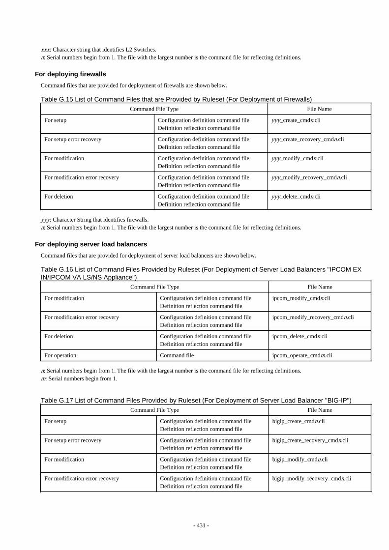
xxx: Character string that identifies L2 Switches.n: Serial numbers begin from 1. The file with the largest number is the command file for reflecting definitions.
For deploying firewalls
Command files that are provided for deployment of firewalls are shown below.
Table G.15 List of Command Files that are Provided by Ruleset (For Deployment of Firewalls)
Command File Type File Name
For setup Configuration definition command fileDefinition reflection command file
yyy_create_cmdn.cli
For setup error recovery Configuration definition command fileDefinition reflection command file
yyy_create_recovery_cmdn.cli
For modification Configuration definition command fileDefinition reflection command file
yyy_modify_cmdn.cli
For modification error recovery Configuration definition command fileDefinition reflection command file
yyy_modify_recovery_cmdn.cli
For deletion Configuration definition command fileDefinition reflection command file
yyy_delete_cmdn.cli
yyy: Character String that identifies firewalls.n: Serial numbers begin from 1. The file with the largest number is the command file for reflecting definitions.
For deploying server load balancers
Command files that are provided for deployment of server load balancers are shown below.
Table G.16 List of Command Files Provided by Ruleset (For Deployment of Server Load Balancers "IPCOM EXIN/IPCOM VA LS/NS Appliance")
Command File Type File Name
For modification Configuration definition command fileDefinition reflection command file
ipcom_modify_cmdn.cli
For modification error recovery Configuration definition command fileDefinition reflection command file
ipcom_modify_recovery_cmdn.cli
For deletion Configuration definition command fileDefinition reflection command file
ipcom_delete_cmdn.cli
For operation Command file ipcom_operate_cmdm.cli
n: Serial numbers begin from 1. The file with the largest number is the command file for reflecting definitions.m: Serial numbers begin from 1.
Table G.17 List of Command Files Provided by Ruleset (For Deployment of Server Load Balancer "BIG-IP")
Command File Type File Name
For setup Configuration definition command fileDefinition reflection command file
bigip_create_cmdn.cli
For setup error recovery Configuration definition command fileDefinition reflection command file
bigip_create_recovery_cmdn.cli
For modification Configuration definition command fileDefinition reflection command file
bigip_modify_cmdn.cli
For modification error recovery Configuration definition command fileDefinition reflection command file
bigip_modify_recovery_cmdn.cli
- 431 -
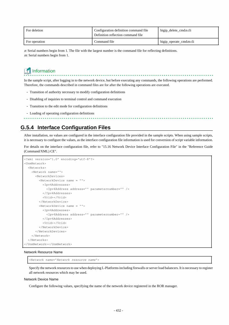
For deletion Configuration definition command fileDefinition reflection command file
bigip_delete_cmdn.cli
For operation Command file bigip_operate_cmdm.cli
n: Serial numbers begin from 1. The file with the largest number is the command file for reflecting definitions.m: Serial numbers begin from 1.
Information
In the sample script, after logging in to the network device, but before executing any commands, the following operations are performed.Therefore, the commands described in command files are for after the following operations are executed.
- Transition of authority necessary to modify configuration definitions
- Disabling of inquiries to terminal control and command execution
- Transition to the edit mode for configuration definitions
- Loading of operating configuration definitions
G.5.4 Interface Configuration FilesAfter installation, no values are configured in the interface configuration file provided in the sample scripts. When using sample scripts,it is necessary to configure the values, as the interface configuration file information is used for conversion of script variable information.
For details on the interface configuration file, refer to "15.16 Network Device Interface Configuration File" in the "Reference Guide(Command/XML) CE".
<?xml version="1.0" encoding="utf-8"?><UnmNetwork> <Networks> <Network name=""> <NetworkDevices> <NetworkDevice name = ""> <Ipv4Addresses> <Ipv4Address address="" parameternumber="" /> </Ipv4Addresses> <Vrid></Vrid> </NetworkDevice> <NetworkDevice name = ""> <Ipv4Addresses> <Ipv4Address address="" parameternumber="" /> </Ipv4Addresses> <Vrid></Vrid> </NetworkDevice> </NetworkDevices> </Network> </Networks></UnmNetwork></UnmNetwork>
Network Resource Name
<Network name="Network resource name">
Specify the network resources to use when deploying L-Platforms including firewalls or server load balancers. It is necessary to registerall network resources which may be used.
Network Device Name
Configure the following values, specifying the name of the network device registered in the ROR manager.
- 432 -
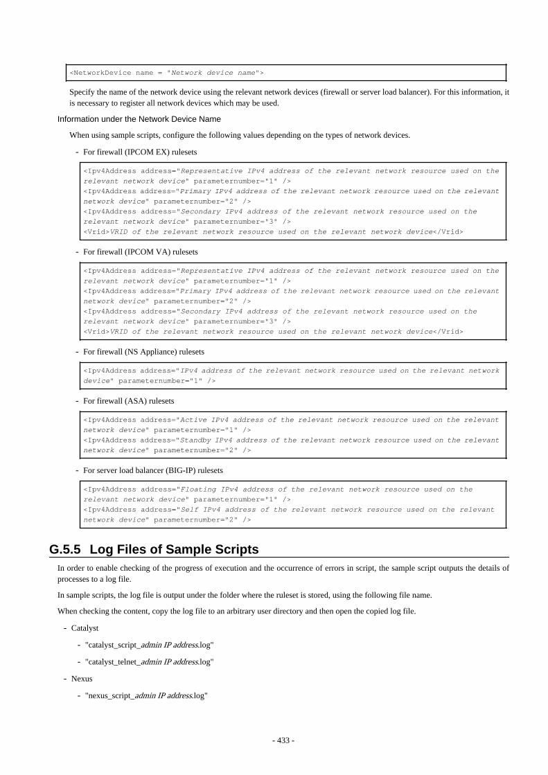
<NetworkDevice name = "Network device name">
Specify the name of the network device using the relevant network devices (firewall or server load balancer). For this information, itis necessary to register all network devices which may be used.
Information under the Network Device Name
When using sample scripts, configure the following values depending on the types of network devices.
- For firewall (IPCOM EX) rulesets
<Ipv4Address address="Representative IPv4 address of the relevant network resource used on the relevant network device" parameternumber="1" /><Ipv4Address address="Primary IPv4 address of the relevant network resource used on the relevant network device" parameternumber="2" /><Ipv4Address address="Secondary IPv4 address of the relevant network resource used on the relevant network device" parameternumber="3" /><Vrid>VRID of the relevant network resource used on the relevant network device</Vrid>
- For firewall (IPCOM VA) rulesets
<Ipv4Address address="Representative IPv4 address of the relevant network resource used on the relevant network device" parameternumber="1" /><Ipv4Address address="Primary IPv4 address of the relevant network resource used on the relevant network device" parameternumber="2" /><Ipv4Address address="Secondary IPv4 address of the relevant network resource used on the relevant network device" parameternumber="3" /><Vrid>VRID of the relevant network resource used on the relevant network device</Vrid>
- For firewall (NS Appliance) rulesets
<Ipv4Address address="IPv4 address of the relevant network resource used on the relevant network device" parameternumber="1" />
- For firewall (ASA) rulesets
<Ipv4Address address="Active IPv4 address of the relevant network resource used on the relevant network device" parameternumber="1" /><Ipv4Address address="Standby IPv4 address of the relevant network resource used on the relevant network device" parameternumber="2" />
- For server load balancer (BIG-IP) rulesets
<Ipv4Address address="Floating IPv4 address of the relevant network resource used on the relevant network device" parameternumber="1" /><Ipv4Address address="Self IPv4 address of the relevant network resource used on the relevant network device" parameternumber="2" />
G.5.5 Log Files of Sample ScriptsIn order to enable checking of the progress of execution and the occurrence of errors in script, the sample script outputs the details ofprocesses to a log file.
In sample scripts, the log file is output under the folder where the ruleset is stored, using the following file name.
When checking the content, copy the log file to an arbitrary user directory and then open the copied log file.
- Catalyst
- "catalyst_script_admin IP address.log"
- "catalyst_telnet_admin IP address.log"
- Nexus
- "nexus_script_admin IP address.log"
- 433 -

- "nexus_telnet_admin IP address.log"
- SR-X
- "srx_script_admin IP address.log"
- "srx_telnet_admin IP address.log"
- IPCOM EX, IPCOM VA, and NSAppliance
- "ipcom_script_admin IP address.log"
- "ipcom_telnet_admin IP address.log"
- ASA 5500
- "asa_script_admin IP address.log"
- "asa_telnet_admin IP address.log"
- BIG-IP LTM
- "bigip_script_admin IP address.log"
- "bigip_ssh_admin IP address.log"
- 434 -
Appendix H Ethernet Fabric DevicesThis appendix explains the method for managing Ethernet fabric devices in Resource Orchestrator.
H.1 Fujitsu PRIMERGY Converged Fabric Switch Blade (10 Gbps18/8+2) and Fujitsu Converged Fabric Switch
This section explains the method for managing Ethernet fabric configured using "Fujitsu PRIMERGY Converged Fabric Switch Blade(10 GPS 18/8+2)" and "Fujitsu CFX 2000 Series".
H.1.1 Management UnitThe configuration example of the Ethernet fabric configured using "Fujitsu PRIMERGY Converged Fabric Switch Blade (10 GPS 18/8+2)"and "Fujitsu CFX 2000 Series" is shown in "Figure H.1 Network Device Management Unit".
Resource Orchestrator manages all devices comprising an Ethernet fabric as a single network device.
For the port name to specify for the link information of the network configuration information necessary for registration as a networkdevice, specify a port with the type EP (End Point) and CIR (Clean Interface with Redundancy). For details on how to confirm the portname to specify, refer to "9.4.8.1 When Creating Network Configuration Information (XML Definition)".
For the admin IP address to specify when stating the network device information in the Network Configuration Information, specify therepresentative virtual IP address of the fabric.
- 435 -

Figure H.1 Network Device Management Unit
H.1.2 Automatic Network ConfigurationWhen the network adjacent to servers is configured using an Ethernet fabric, automatic migration of port profiles (hereinafter AMPP) canbe used for L-Servers. The AMPP function works with L-Server migration and automatically migrates the physical switch portconfiguration to the physical port of the Ethernet fabric switch connected to the destination server.
Resource Orchestrator supports VLAN as a parameter of AMPP. The ARP method is used for realizing AMPP.
When creating network resources, by setting auto-configuration, a VLAN port profile is created for an Ethernet fabric switch with portprofile configuration enabled. When creating a single network resource, a single VLAN port profile is created on an Ethernet fabric switch.
When creating an L-Server, link the NIC of the L-Server with the VLAN port profile.
When auto-configuration for network resources is valid, link them with the port profile auto-configured by Resource Orchestrator. Forthe cases other than the above, link them with the port profile based on the description in the port profile configuration function definitionfile. Through this, VLANs are configured for the internal port ("End Point") of the Ethernet Fabric for L-Server communication.
For details on automatic network configuration, refer to "9.4.1.9 Automatic Network Configuration for Ethernet Fabric Switches".
For details on the port profile configuration function definition file, refer to "9.4.8.4 When Using Port Profile Configuration Files".
- 436 -
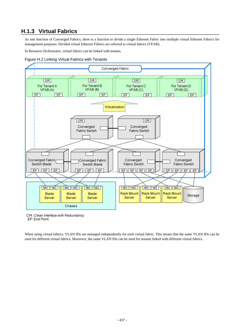
H.1.3 Virtual FabricsAs one function of Converged Fabrics, there is a function to divide a single Ethernet Fabric into multiple virtual Ethernet Fabrics formanagement purposes. Divided virtual Ethernet Fabrics are referred to virtual fabrics (VFAB).
In Resource Orchestrator, virtual fabrics can be linked with tenants.
Figure H.2 Linking Virtual Fabrics with Tenants
When using virtual fabrics, VLAN IDs are managed independently for each virtual fabric. This means that the same VLAN IDs can beused for different virtual fabrics. Moreover, the same VLAN IDs can be used for tenants linked with different virtual fabrics.
- 437 -
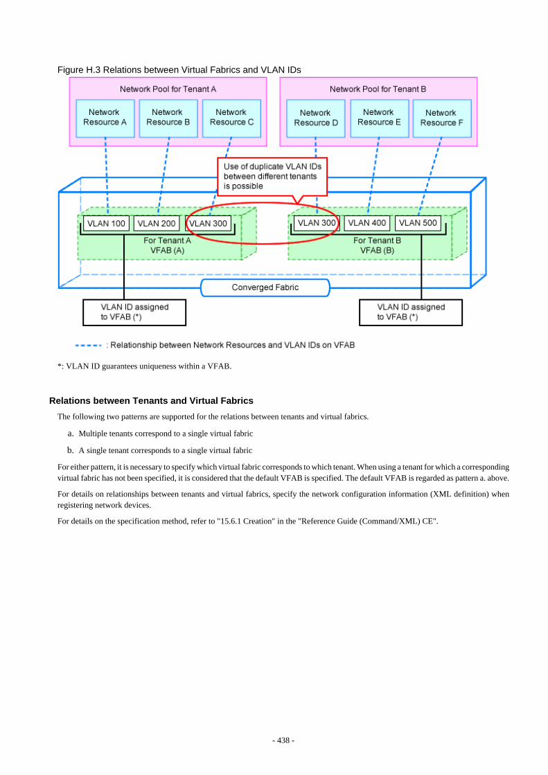
Figure H.3 Relations between Virtual Fabrics and VLAN IDs
*: VLAN ID guarantees uniqueness within a VFAB.
Relations between Tenants and Virtual Fabrics
The following two patterns are supported for the relations between tenants and virtual fabrics.
a. Multiple tenants correspond to a single virtual fabric
b. A single tenant corresponds to a single virtual fabric
For either pattern, it is necessary to specify which virtual fabric corresponds to which tenant. When using a tenant for which a correspondingvirtual fabric has not been specified, it is considered that the default VFAB is specified. The default VFAB is regarded as pattern a. above.
For details on relationships between tenants and virtual fabrics, specify the network configuration information (XML definition) whenregistering network devices.
For details on the specification method, refer to "15.6.1 Creation" in the "Reference Guide (Command/XML) CE".
- 438 -
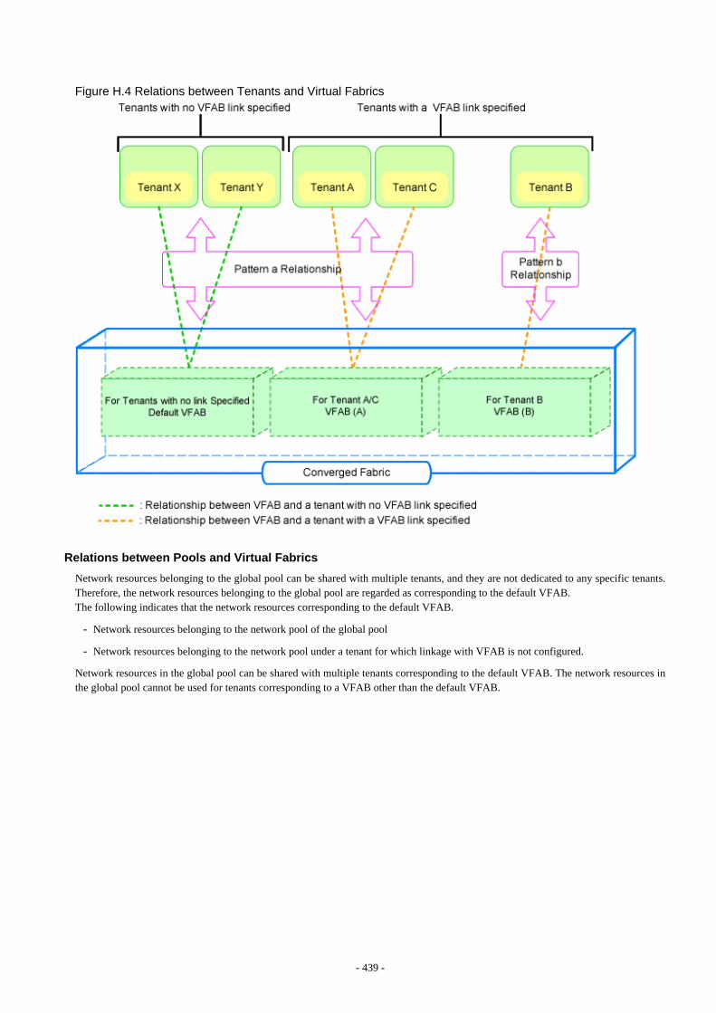
Figure H.4 Relations between Tenants and Virtual Fabrics
Relations between Pools and Virtual Fabrics
Network resources belonging to the global pool can be shared with multiple tenants, and they are not dedicated to any specific tenants.Therefore, the network resources belonging to the global pool are regarded as corresponding to the default VFAB.The following indicates that the network resources corresponding to the default VFAB.
- Network resources belonging to the network pool of the global pool
- Network resources belonging to the network pool under a tenant for which linkage with VFAB is not configured.
Network resources in the global pool can be shared with multiple tenants corresponding to the default VFAB. The network resources inthe global pool cannot be used for tenants corresponding to a VFAB other than the default VFAB.
- 439 -
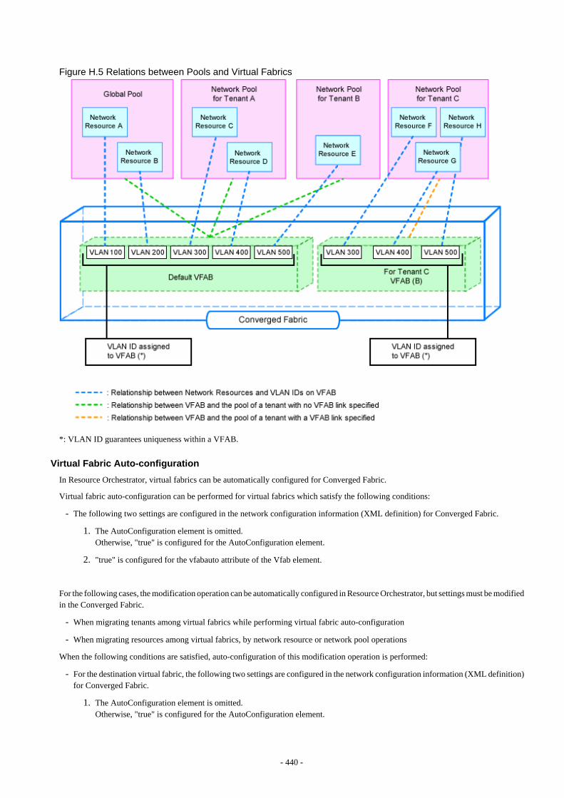
Figure H.5 Relations between Pools and Virtual Fabrics
*: VLAN ID guarantees uniqueness within a VFAB.
Virtual Fabric Auto-configuration
In Resource Orchestrator, virtual fabrics can be automatically configured for Converged Fabric.
Virtual fabric auto-configuration can be performed for virtual fabrics which satisfy the following conditions:
- The following two settings are configured in the network configuration information (XML definition) for Converged Fabric.
1. The AutoConfiguration element is omitted.Otherwise, "true" is configured for the AutoConfiguration element.
2. "true" is configured for the vfabauto attribute of the Vfab element.
For the following cases, the modification operation can be automatically configured in Resource Orchestrator, but settings must be modifiedin the Converged Fabric.
- When migrating tenants among virtual fabrics while performing virtual fabric auto-configuration
- When migrating resources among virtual fabrics, by network resource or network pool operations
When the following conditions are satisfied, auto-configuration of this modification operation is performed:
- For the destination virtual fabric, the following two settings are configured in the network configuration information (XML definition)for Converged Fabric.
1. The AutoConfiguration element is omitted.Otherwise, "true" is configured for the AutoConfiguration element.
- 440 -
2. "true" is configured for the vfabauto attribute of the Vfab element.
Moreover, in addition to the conditions above, when the following conditions are satisfied, the configuration of the virtual fabric informationrelated to the port profile configured in Resource Orchestrator is modified automatically.
- The Netdevice element in the portprofile attribute has been omitted in the network configuration information (XML definition).Otherwise, "enable" is configured in the portprofile attribute.
The default VFAB is not the target of auto-configuration, as it is the virtual fabric which was configured in the device when installingConverged Fabric. Therefore, the values specified in the vfabauto attribute in the Vfab element in the network configuration information(XML definition) have no meaning. They are treated as if "false" is specified.
At the timing of the first auto-configuration, auto-configuration of virtual fabrics is performed on the condition that "pre-configurationinvolving the target virtual fabric in the target virtual Converged Fabric has not been performed". This condition defines the status thatthe following has been satisfied:
1. The vfab use command has not been executed for the relevant virtual fabric, and
2. The vfab mode command has not been executed for the relevant virtual fabric, and
3. The vfab cir-ports command has not been executed for the relevant virtual fabric, and
4. The ports in dot1ad mode that use the relevant virtual fabric are in either one of the following statuses:
- Do not belong to the interface group for Converged Fabric.
- Belong to only the Converged Fabric interface group which is composed of the ports in dot1ad mode. Moreover, VLAN is notconfigured for the interface group.
When auto-configuration cannot be performed, as the conditions above are not satisfied, operation is as below.
- When registering or modifying the network devices for Converged Fabric
When even a single auto-configuration among virtual fabrics of the auto-configuration targets to be registered or modified cannot beperformed, registration or modification of Converged Fabric network devices fails.
When registration or modification fail, after performing either of the following corrective actions, perform registration or modificationof network devices for Converged Fabric again.
- Delete the virtual fabric for which auto-configuration could not be performed from the network configuration information (XMLdefinition).
- Modify the hardware settings for Converged Fabric to satisfy the conditions above.
- When performing batch registration or modification of network devices for Converged Fabric
When registration or modification of multiple Converged Fabrics is performed, if there is even one Converged Fabric which cannotbe automatically configured, registration or modification will fail. Other Converged Fabrics are processed as below.
- Registration or modification of Converged Fabrics which were defined before the failure are performed correctly.
- Converged Fabrics which were defined after the failure are not registered or modified.
When registration or modification fail, perform either of the following corrective actions, and then perform batch registration ormodification of network devices for Converged Fabrics which have been defined after the failure again.
- Delete the virtual fabric for which auto-configuration could not be performed from the network configuration information (XMLdefinition).
- Modify the hardware settings for Converged Fabric to satisfy the conditions above.
- 441 -
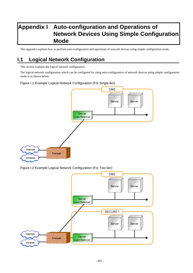
Appendix I Auto-configuration and Operations ofNetwork Devices Using Simple ConfigurationMode
This appendix explains how to perform auto-configuration and operations of network devices using simple configuration mode.
I.1 Logical Network ConfigurationThis section explains the logical network configuration.
The logical network configuration which can be configured by using auto-configuration of network devices using simple configurationmode is as shown below.
Figure I.1 Example Logical Network Configuration (For Single-tier)
Figure I.2 Example Logical Network Configuration (For Two-tier)
- 442 -
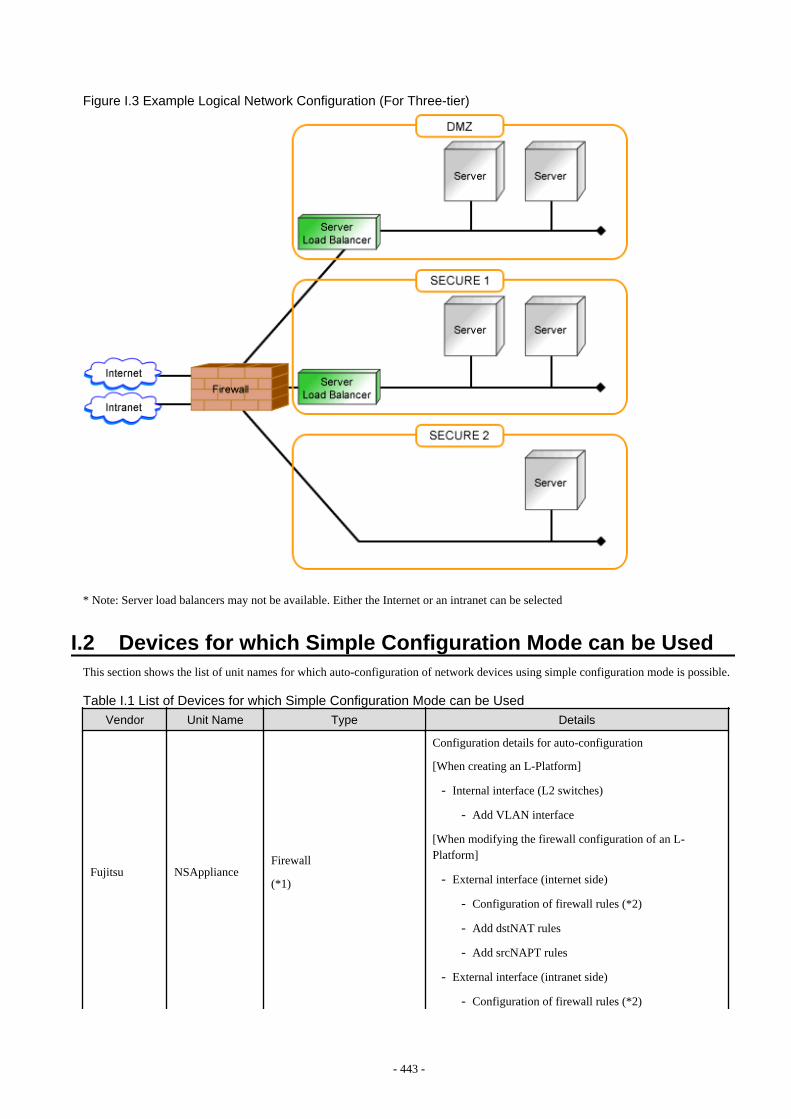
Figure I.3 Example Logical Network Configuration (For Three-tier)
* Note: Server load balancers may not be available. Either the Internet or an intranet can be selected
I.2 Devices for which Simple Configuration Mode can be UsedThis section shows the list of unit names for which auto-configuration of network devices using simple configuration mode is possible.
Table I.1 List of Devices for which Simple Configuration Mode can be Used
Vendor Unit Name Type Details
Fujitsu NSApplianceFirewall
(*1)
Configuration details for auto-configuration
[When creating an L-Platform]
- Internal interface (L2 switches)
- Add VLAN interface
[When modifying the firewall configuration of an L-Platform]
- External interface (internet side)
- Configuration of firewall rules (*2)
- Add dstNAT rules
- Add srcNAPT rules
- External interface (intranet side)
- Configuration of firewall rules (*2)
- 443 -
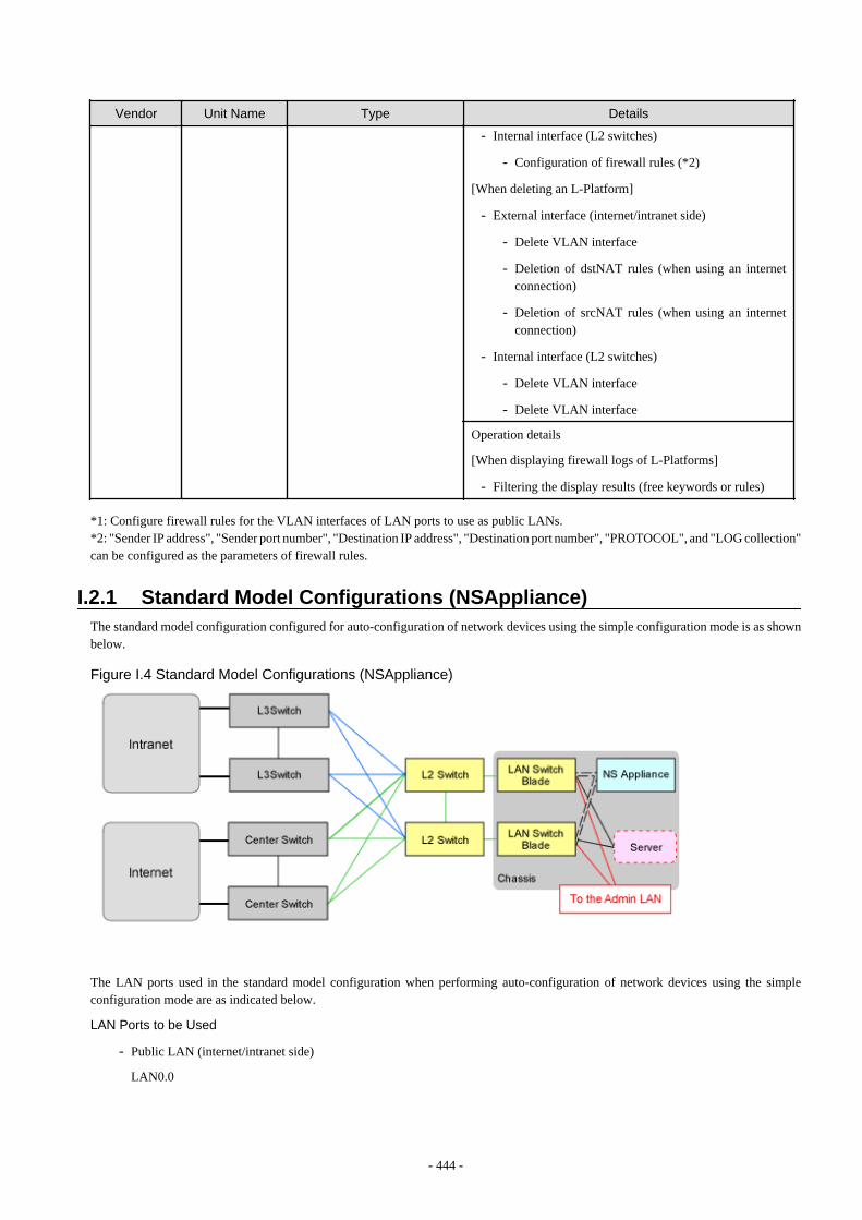
Vendor Unit Name Type Details
- Internal interface (L2 switches)
- Configuration of firewall rules (*2)
[When deleting an L-Platform]
- External interface (internet/intranet side)
- Delete VLAN interface
- Deletion of dstNAT rules (when using an internetconnection)
- Deletion of srcNAT rules (when using an internetconnection)
- Internal interface (L2 switches)
- Delete VLAN interface
- Delete VLAN interface
Operation details
[When displaying firewall logs of L-Platforms]
- Filtering the display results (free keywords or rules)
*1: Configure firewall rules for the VLAN interfaces of LAN ports to use as public LANs.*2: "Sender IP address", "Sender port number", "Destination IP address", "Destination port number", "PROTOCOL", and "LOG collection"can be configured as the parameters of firewall rules.
I.2.1 Standard Model Configurations (NSAppliance)The standard model configuration configured for auto-configuration of network devices using the simple configuration mode is as shownbelow.
Figure I.4 Standard Model Configurations (NSAppliance)
The LAN ports used in the standard model configuration when performing auto-configuration of network devices using the simpleconfiguration mode are as indicated below.
LAN Ports to be Used
- Public LAN (internet/intranet side)
LAN0.0
- 444 -
- For Public LANs (L2 Switch Side)
LAN0.1
- For the Admin LAN
LAN0.3
Information
For public LAN (internet/intranet side), configure the NS appliance referring to "3.6 Configuring NS Appliances" in the "NS OptionInstruction".
I.2.2 Usage Conditions for Standard Model ConfigurationThis section explains the usage conditions for standard model configuration.
Information
When using auto-configuration of network devices using the simple configuration mode, configure the target devices in advance accordingto "9.2.3.3 Settings for Automatically Configured Devices".
For details on pre-configuration for the NS appliance (NS Option), refer to "2.2.2 Preparations for NS Appliance" in the "NS OptionInstruction".
NS Appliance
- An L-Platform is comprised of one to three-tier network segments.
- Up to 10 L-Servers can be deployed in a single network segment.
- The maximum number of firewall rules which can be configured in an L-Platform is 180.
- Up to five L-Platforms can be created for a single NS appliance.
- Only a single NS appliance using the "simple configuration mode" can be registered for a single tenant.
I.3 PreparationsThis section explains pre-configuration necessary for using auto-configuration of network devices using the simple configuration mode.
I.3.1 Interface Configuration FilesWhen performing auto-configuration of network devices using simple configuration mode, it is necessary to create the interfaceconfiguration file. Refer to "15.16 Network Device Interface Configuration File" in the "Reference Guide (Command/XML) CE" fordetails.
Deployment Location for Interface Configuration Files
[Windows Manager]Installation_folder\SVROR\Manager\etc\scripts\network_resource\
[Linux Manager]/etc/opt/FJSVrcvmr/scripts/network_resource/
Format
NS Appliance
<?xml version="1.0" encoding="utf-8"?><UnmNetwork>
- 445 -

<Networks> <Network name="Network resource name"> <NetworkDevices> <NetworkDevice name="Network device name"> <Ipv4Addresses> <Ipv4Address address="Default gateway" parameternumber="1" /> </Ipv4Addresses> </NetworkDevice> : </NetworkDevices> : </Network> : </Networks></UnmNetwork>
Network Resource Name
<Network name="Network resource name">
Specify the network resources to use when deploying L-Platforms.It is necessary to register all network resources which may be used.
Network Device Name
<NetworkDevice name="Network device name">
For the network device name, specify the network device name of the NS appliance which is the configuration target of the simpleconfiguration mode used for the network resources.
Information under the Network Device Name
Configure the following values depending on the types of network devices.
<Ipv4Address address="Default gateway" parameternumber="1" />
Default gateway
Specify the IPv4 address of the default gateway in the network resource used on the relevant network device for the defaultgateway.
I.4 RulesetsWhen performing auto-configuration or operations for network devices using simple configuration mode, use the built-in ruleset toconfigure the network devices. The ruleset names displayed in messages, when performing auto-configuration and operations of networkdevices using simple configuration mode, are indicated below.
NS Appliance
- Ruleset for configuration
_Simple_FW_setting_for_NS
- Ruleset for operation
_Simple_log_display_for_NS
I.5 Definition fileModify the definition to use for auto-configuration and operations of network devices using the simple configuration mode, by configuringthe values in the definition file in advance.
- 446 -
I.5.1 Storage Location of the Definition File[Windows Manager]Installation_folder\SVROR\Manager\etc\customize_data
[Linux Manager]/etc/opt/FJSVrcvmr/customize_data
I.5.2 Definition File Nameunm_provisioning.rcxprop
I.5.3 Definition File FormatThis section explains the definition information to use for auto-configuration and operations of network devices using the simpleconfiguration mode.
Monitoring Time of Script
Specify the monitoring time when you want to change it to a value besides 1200(s).
Information
In the network device automatic configuration function, script execution time is monitored.When the monitoring time has passed since the beginning of the script execution, the processing of the script is terminated.
Parameter Format of Definition Files
SIMPLE_SCRIPT_EXECUTE_TIMEOUT=Monitoring time
Specify the monitoring time within the range of 1 to 7200(s).
When the specified value is non-numeric or is outside of the above-mentioned range, 1200(s) is used.
Example
SIMPLE_SCRIPT_EXECUTE_TIMEOUT=1800
I.6 Collecting Troubleshooting Data when an Error OccursThis section explains how to collect troubleshooting data necessary for determination of causes or recovery of auto-configuration details,when auto-configuration of network devices fails, while using auto-configuration of network devices with the simple configuration mode.
When auto-configuration for network devices fails, take corrective action or confirm operations depending on the output messages.
If, as the result of confirmation of operations, the cause of auto-configuration failure cannot be removed, collect the output message andtroubleshooting data, and request investigation by Fujitsu technical staff.
The troubleshooting data to collect is as follows:
- Simple configuration log files
- Troubleshooting data of network devices
- Troubleshooting data of admin servers
I.6.1 Simple Configuration Log FilesWhen performing auto-configuration of network devices using simple configuration mode, the operation details are output in the files aslogs.
- 447 -
When requesting investigation by Fujitsu technical staff, copy the log files stored in the following locations, and send them.
Note that the storage locations and the file names of the log files are different depending on the models of target network devices for whichauto-configuration failed.
- NS Appliance
- Storage directories
[Windows Manager]Installation_folder\SVROR\Manager\etc\scripts\Simple\Fujitsu\NSAppliance\rulesets\_Simple_FW_setting_for_NSInstallation_folder\SVROR\Manager\etc\scripts\Simple\Fujitsu\NSAppliance\operations\_Simple_log_display_for_NS
[Linux Manager]/etc/opt/FJSVrcvmr/scripts/Simple/Fujitsu/NSAppliance/rulesets/_Simple_FW_setting_for_NS/etc/opt/FJSVrcvmr/scripts/Simple/Fujitsu/NSAppliance/operations/_Simple_log_display_for_NS
- Log file names
- "ns_script_admin IP address.log"
- ns_script_unknown_device.log
I.6.2 Troubleshooting Data of Network DevicesCollect the troubleshooting data (maintenance data, etc.) for investigation of network devices for which auto-configuration failed.
For details on how to collect the data necessary for investigation, refer to the manuals of the relevant network devices.
I.6.3 Troubleshooting Data of Admin ServersCollect the data necessary for investigation of admin servers.
For details on how to collect troubleshooting data of admin servers, refer to "1.3 Collecting Investigation Data(Cloud Edition)" in"Troubleshooting".
- 448 -

Appendix J IPCOM VX Series DevicesThis appendix explains the method for managing IPCOM VX series devices in Resource Orchestrator.
J.1 IPCOM VX SeriesThis section explains how to manage IPCOM VX series devices configured for linking with Ethernet fabrics.
J.1.1 Management UnitA configuration example of IPCOM VX series configured for linking with Ethernet fabrics is shown in "Figure J.1 Network Device(IPCOM VX Series) Management Unit".
Resource Orchestrator manages IP VX series devices as a single management host network device. Each IPCOM VA in an IPCOM VXseries device is managed as a network device (firewall or server load balancer).
For the port name of the Ethernet fabric to specify for the link information of the network configuration information necessary forregistration as a network device, specify an IEEE802.1ad frame communication port with the type EP (End Point) and CIR (Clean Interfacewith Redundancy). The port type cares about neither EP nor CIR. For details on how to confirm the port name to specify, refer to "9.4.8.1When Creating Network Configuration Information (XML Definition)".
For the admin IP address to specify when stating the network device information in the network configuration information, specify theadmin IP address configured for the IPCOPM VX series device or IPCOM VA.
The following configurations have been described assuming that VFAB is set to the network mode.
- 449 -

Figure J.1 Network Device (IPCOM VX Series) Management Unit
J.1.2 IPCOM VAThe IPCOM VX series provides the functions to deploy and manage multiple virtual network devices (IPCOM VA).
Resource Orchestrator can link each IPCOM VA with tenants in coordination with virtual fabrics using Ethernet fabric.
- 450 -

Figure J.2 Linking IPCOM VA and Virtual Fabrics with Tenants
When using virtual fabrics, a VFAB VLAN ID (S-TAG ID) for the fabric ID of each virtual fabric is configured independently. In orderto enable communication between IPCOM VA and virtual fabrics, the S-TAG IDs of both the IPCOM VA and the virtual fabric must bethe same.
There are following two patterns for matching the S-TAG IDs of IPCOM VA and virtual fabrics:
- Configuration matching S-TAG IDs between IPCOM VA and virtual fabric
For details on configuration, refer to "Figure J.3 Relationship of S-TAG IDs of IPCOM VA and Virtual Fabrics".
- Configuration matching S-TAG IDs between each interface of IPCOM VA and virtual fabrics
For details on configuration, refer to "Figure J.4 Relationship of S-TAG IDs of IPCOM VA and Multiple Virtual Fabrics".
- 451 -
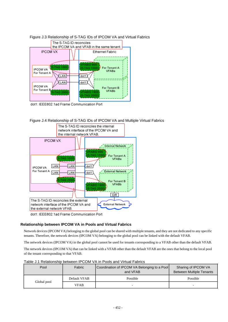
Figure J.3 Relationship of S-TAG IDs of IPCOM VA and Virtual Fabrics
Figure J.4 Relationship of S-TAG IDs of IPCOM VA and Multiple Virtual Fabrics
Relationship between IPCOM VA in Pools and Virtual Fabrics
Network devices (IPCOM VA) belonging to the global pool can be shared with multiple tenants, and they are not dedicated to any specifictenants. Therefore, the network devices (IPCOM VA) belonging to the global pool can be linked with the default VFAB.
The network devices (IPCOM VA) in the global pool cannot be used for tenants corresponding to a VFAB other than the default VFAB.
The network devices (IPCOM VA) that can be linked with a VFAB other than the default VFAB are the ones that belong to the local poolof the tenant corresponding to that VFAB.
Table J.1 Relationship between IPCOM VA in Pools and Virtual Fabrics
Pool Fabric Coordination of IPCOM VA Belonging to a Pooland VFAB
Sharing of IPCOM VABetween Multiple Tenants
Global poolDefault VFAB Possible Possible
VFAB - -
- 452 -
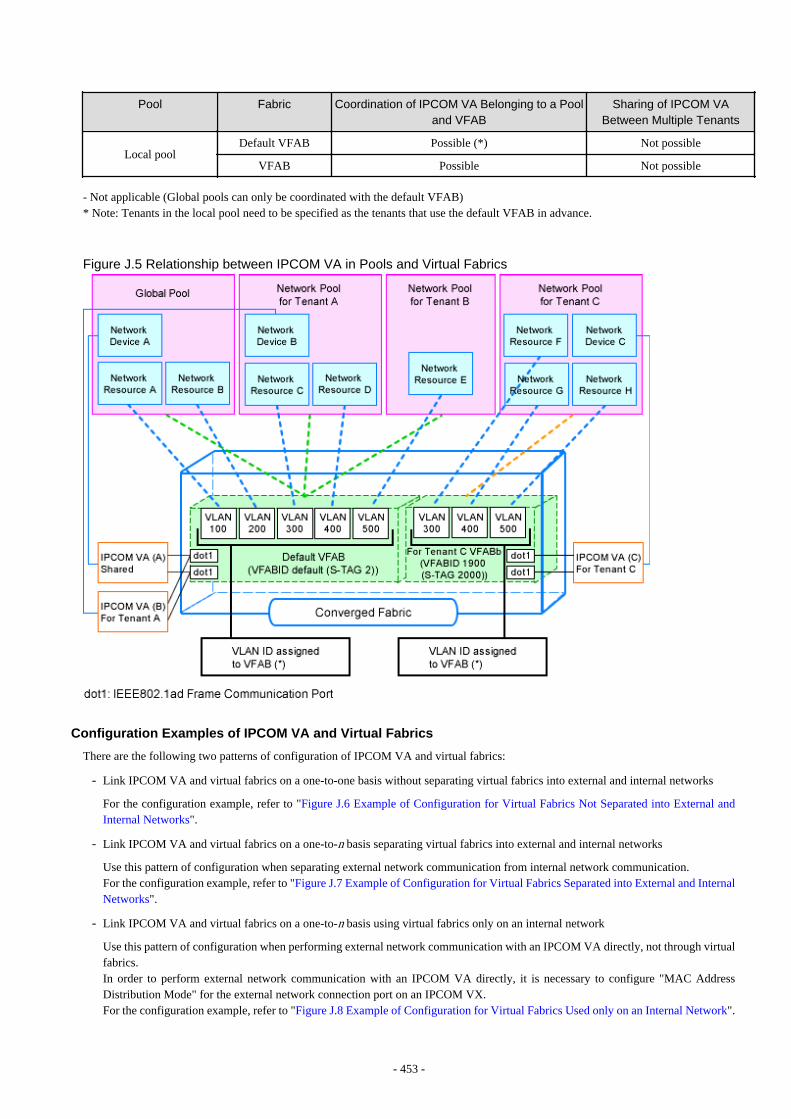
Pool Fabric Coordination of IPCOM VA Belonging to a Pooland VFAB
Sharing of IPCOM VABetween Multiple Tenants
Local poolDefault VFAB Possible (*) Not possible
VFAB Possible Not possible
- Not applicable (Global pools can only be coordinated with the default VFAB)* Note: Tenants in the local pool need to be specified as the tenants that use the default VFAB in advance.
Figure J.5 Relationship between IPCOM VA in Pools and Virtual Fabrics
Configuration Examples of IPCOM VA and Virtual Fabrics
There are the following two patterns of configuration of IPCOM VA and virtual fabrics:
- Link IPCOM VA and virtual fabrics on a one-to-one basis without separating virtual fabrics into external and internal networks
For the configuration example, refer to "Figure J.6 Example of Configuration for Virtual Fabrics Not Separated into External andInternal Networks".
- Link IPCOM VA and virtual fabrics on a one-to-n basis separating virtual fabrics into external and internal networks
Use this pattern of configuration when separating external network communication from internal network communication.For the configuration example, refer to "Figure J.7 Example of Configuration for Virtual Fabrics Separated into External and InternalNetworks".
- Link IPCOM VA and virtual fabrics on a one-to-n basis using virtual fabrics only on an internal network
Use this pattern of configuration when performing external network communication with an IPCOM VA directly, not through virtualfabrics.In order to perform external network communication with an IPCOM VA directly, it is necessary to configure "MAC AddressDistribution Mode" for the external network connection port on an IPCOM VX.For the configuration example, refer to "Figure J.8 Example of Configuration for Virtual Fabrics Used only on an Internal Network".
- 453 -
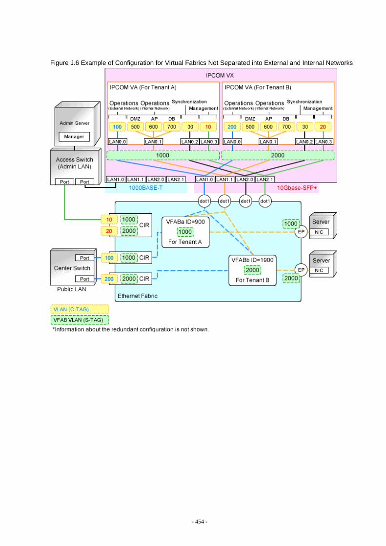
Figure J.6 Example of Configuration for Virtual Fabrics Not Separated into External and Internal Networks
- 454 -
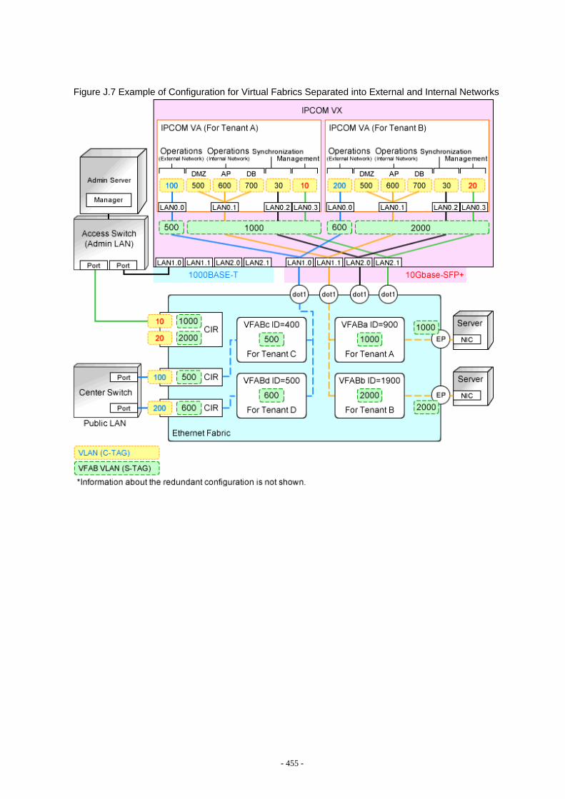
Figure J.7 Example of Configuration for Virtual Fabrics Separated into External and Internal Networks
- 455 -

Figure J.8 Example of Configuration for Virtual Fabrics Used only on an Internal Network
- 456 -
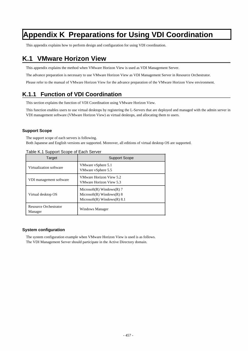
Appendix K Preparations for Using VDI CoordinationThis appendix explains how to perform design and configuration for using VDI coordination.
K.1 VMware Horizon ViewThis appendix explains the method when VMware Horizon View is used as VDI Management Server.
The advance preparation is necessary to use VMware Horizon View as VDI Management Server in Resource Orchestrator.
Please refer to the manual of VMware Horizon View for the advance preparation of the VMware Horizon View environment.
K.1.1 Function of VDI CoordinationThis section explains the function of VDI Coordination using VMware Horizon View.
This function enables users to use virtual desktops by registering the L-Servers that are deployed and managed with the admin server inVDI management software (VMware Horizon View) as virtual desktops, and allocating them to users.
Support Scope
The support scope of each servers is following.Both Japanese and English versions are supported. Moreover, all editions of virtual desktop OS are supported.
Table K.1 Support Scope of Each Server
Target Support Scope
Virtualization softwareVMware vSphere 5.1VMware vSphere 5.5
VDI management softwareVMware Horizon View 5.2VMware Horizon View 5.3
Virtual desktop OSMicrosoft(R) Windows(R) 7Microsoft(R) Windows(R) 8Microsoft(R) Windows(R) 8.1
Resource OrchestratorManager
Windows Manager
System configuration
The system configuration example when VMware Horizon View is used is as follows.The VDI Management Server should participate in the Active Directory domain.
- 457 -
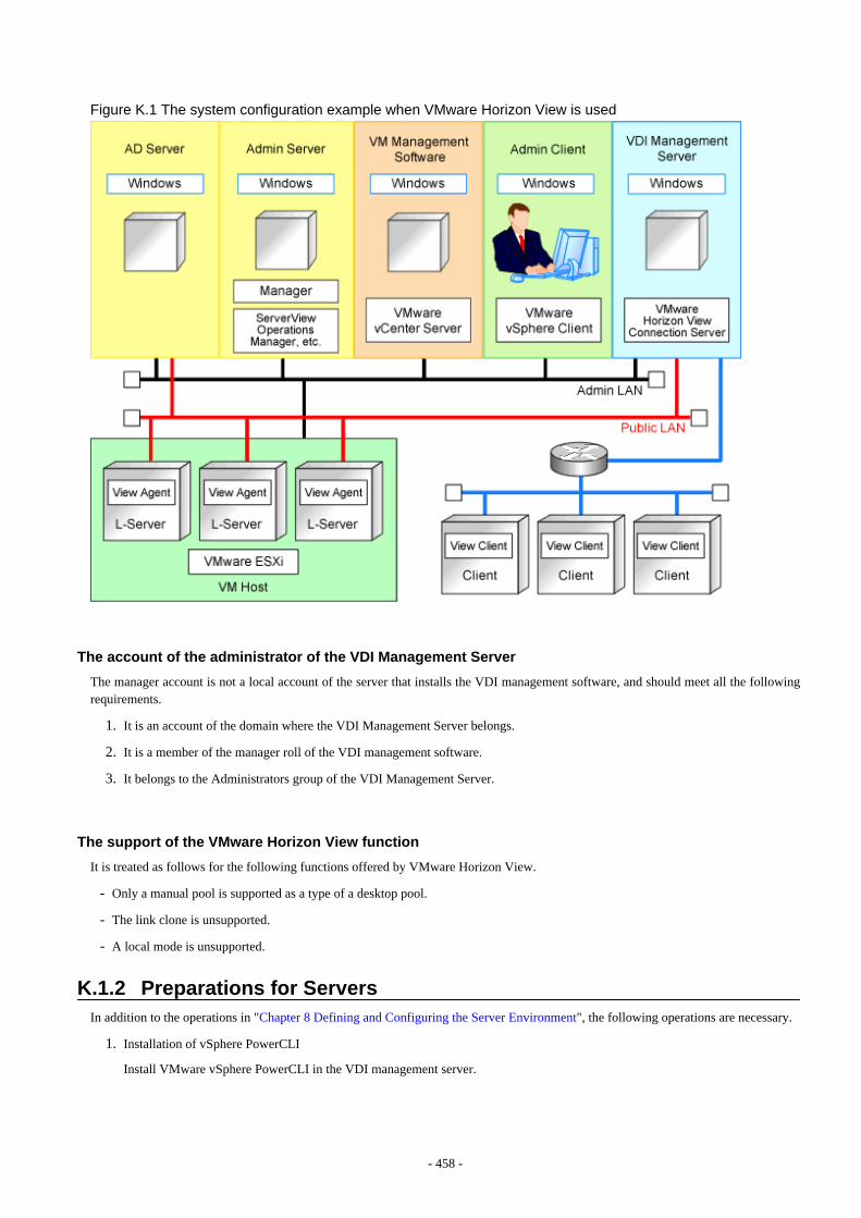
Figure K.1 The system configuration example when VMware Horizon View is used
The account of the administrator of the VDI Management Server
The manager account is not a local account of the server that installs the VDI management software, and should meet all the followingrequirements.
1. It is an account of the domain where the VDI Management Server belongs.
2. It is a member of the manager roll of the VDI management software.
3. It belongs to the Administrators group of the VDI Management Server.
The support of the VMware Horizon View function
It is treated as follows for the following functions offered by VMware Horizon View.
- Only a manual pool is supported as a type of a desktop pool.
- The link clone is unsupported.
- A local mode is unsupported.
K.1.2 Preparations for ServersIn addition to the operations in "Chapter 8 Defining and Configuring the Server Environment", the following operations are necessary.
1. Installation of vSphere PowerCLI
Install VMware vSphere PowerCLI in the VDI management server.
- 458 -

2. Setting of VMware script
a. The Infrastructure Administrator sets the VMware script in the VDI management server according to the following procedures.
The VMware scripts are under the following folder of this product.
[Windows manager]installation_folder\SVROR\Manager\opt\FJSVrcxmr\sys\VMwareViewScript
- AddRemovePoolVms.ps1
- MachineId.ps1
b. Copy these scripts of "a" under the following folder in the VDI management server.
VMware_Horizon_View_installation_folder\extras\PowerShell\
3. Configuration of winrm
Configure remote administration on VDI management server.
Login to the VDI management server using administrative privileges and execute the following command from the command prompt.Enter "y", when requested.
> winrm quickconfig <RETURN>
4. Configuration of TrustedHosts
Configure remote management authentication settings on the machine the Resource Orchestrator admin server will be set up.
a. Log on to the admin server as the administrator.
b. Execute the following command from the command prompt to record the configuration details for TrustedHosts.
>winrm get winrm/config/client <RETURN>
Record the displayed details in TrustedHosts.
Example
When multiple VDI Management Servers are registered
192.168.1.100, 192.168.1.101
When a single asterisk ("*") is displayed, the following procedure is unnecessary as all hosts will be trusted in theconfiguration.
c. Execute the following command.
Enter the result obtained from b. for Recorded_content_in_b.
>winrm set winrm/config/client @{TrustedHosts="Recorded_content_in_b. , Additionally_ registered_VDIManagement Server_address"} <RETURN>
Example
The command specification when multiple VDI Management Servers are registered
>winrm set winrm/config/client @{TrustedHosts="192.168.1.100, 192.168.1.101, Additionally_registered_SCVMM_address"} <RETURN>
d. Execute the following command to check the details for TrustedHosts.
>winrm get winrm/config/client <RETURN>
- 459 -
If the address of the VDI management server additionally registered has been added to the details recorded in b., there are noproblems.
Note
When registering multiple VDI Management Servers in Resource Orchestrator as VM management software, specify the IPaddresses for multiple VM management software separated by commas (",") using the command for registering TrustedHosts.
5. Change of PowerShell execution policy
On the machine the Resource Orchestrator admin server and VDI management server, change the PowerShell execution policy to"RemoteSigned".Start the PowerShell console using administrator privileges and execute the following command:
>Set-ExecutionPolicy -ExecutionPolicy RemoteSigned <RETURN>
Note
When VDI management server does not connect with the Internet, by fault to need long time for loading of View PowerCLI snap inn,creation and deletion processing of L-Server are inhibited.Please connect the VDI management server to the Internet.
When you cannot connect VDI management server to the Internet, execute the setting of Internet Explorer according to the followingprocedures.
1. Log in the VDI Management Server with the account of the administrator of the VDI Management Server explained in "K.1.1Function of VDI Coordination".
2. Start Internet Explorer, and uncheck the following check box.
[Internet Options] - [Advanced] tab - [Check for publisher's certificate revocation]
- 460 -