Embed Size (px)
Citation preview

8
Design Aspects of a Testbed for an IPv6-Based Future Network for Aeronautical Safety and
Non-Safety Communication
Oliver Lücke and Eriza Hafid Fazli TriaGnoSys GmbH
Germany
1. Introduction
In this chapter, the development of a networking testbed to test and validate IPv6-based protocols for future Air Traffic Management (ATM) network is presented. The development was originally initiated within the EC FP6 project NEWSKY (Networking the Sky for Aeronautical Communications), which aimed at developing a concept for a global, heterogeneous communication network for aeronautical communications, based on IPv6 protocol stack. The NEWSKY network integrates different applications (ATS, AOC, AAC, and APC) and different data link technologies (legacy and future long range terrestrial radio, satellite, airport data link, etc.) using a common IPv6 network layer. For proof-of-concept, the NEWSKY testbed has successfully implemented NEWSKY network mobility, handover, and quality of service solutions, and tested and demonstrated them over real satellite link (Fazli et al., 2009). Also the EC FP7 project SANDRA (Seamless Aeronautical Networking through integration of Data-Links, Radios and Antennas) aims at designing and implementing an integrated aeronautical communication system and validating it through a testbed and, further, in-flight trials on an A320 (SANDRA web page, 2011). Central design paradigm is the improvement of efficiency and cost-effectiveness by ensuring a high degree of flexibility, scalability, modularity and re-configurability. Whereas the NEWSKY testbed is considered to be a proof-of-concept, the SANDRA testbed will represent a proof-of-principle prototype aircraft communication system, integrating prototypes developed and implemented in SANDRA, comprising AeroMACS, Integrated Modular Radio (IMR), Integrated Router (IR), and a novel Ku-band electronically steerable antenna array. SANDRA focuses on the air-to-ground communication and on the development of the on-board airborne SANDRA terminal. The SANDRA terminal, in particular the IR and the IMR have to jointly implement the capabilities of resource allocation among heterogeneous link access technologies and link reconfigurability (e.g. when new links become available or previously available become unavailable, including handover between links). The required technology-dependent functions (such as control of the heterogeneous link technologies) reside in the IMR, whereas technology-independent functions are implemented in the IR, while using IP to achieve convergence and interoperability between the different link access
www.intechopen.com
Future Aeronautical Communications
172
technologies. Although the focus is on the airborne terminal, the testbed of course also has to implement a ground network side. The main aspects of the testbed design and the testbed core concepts and components are presented in this chapter, namely the security and QoS (quality of service) provision concepts for segregation of safety and non-safety domains in an integrated system, the Integrated Router, IPv6 and IPv4 internetworking. This chapter is organised as follows. First, in Sec. 2 the NEWSKY project will be shortly described, including the study objectives and the architecture of the IPv6 network testbed for NEWSKY demonstration is also described. The following Sec. 3 contains a short overview of the SANDRA main goals and testbed purpose. The main differences of the SANDRA testbed from the NEWSKY testbed will become evident. This includes improvements in the protocols and configuration taking into account lessons learnt in NEWSKY, additional features such as automatic modem and bandwidth control, Integrated Modular Radio (IMR), and the additional requirement that the testbed shall be integrated in an Airbus A320 for in-flight test. Sec. 4 focuses on presenting the overall SANDRA testbed network architecture. This includes a reference network architecture, which is independent of restrictions specific to the testbed implementation, and the actual testbed network architecture which has to take into account various constraints, e.g. unavailability of IPv6 satellite access networks. Sec. 5 presents in some more detail selected topics related to the SANDRA testbed which are specifically interesting aspects of implementation and investigation, such as IPv6 over IPv4 network traversal and header compression. Finally, Sec. 6 gives a short summary and presents the next steps and schedule for the testbed implementation and laboratory and flight trials.
2. NEWSKY testbed overview
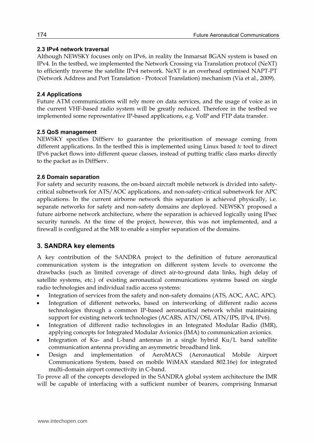
The main objective of the laboratory testbed development in NEWSKY was to implement some basic functionalities of the NEWSKY networking design, in particular with respect to mobility, security, and QoS aspects. However, due to the constraints within the project, not all design aspects were implemented in the testbed. This section describes the NEWSKY testbed architecture, components, and points out the differences between the design and the implementation wherever applicable. The laboratory testbed consists of two main subnetworks: the airborne mobile network representing an aircraft, and the ground network representing a connected ATC and airline network, and the public Internet. The two main subnetworks are connected by two different data links. The network architecture is depicted in Fig. 1. The airborne network consists of the Mobile Network Node (MNN) and the Mobile Router (MR). The MNN represents the airborne user terminal, which could belong either to the cockpit (e.g. an interface for pilot-ATC communication) or to the cabin (e.g. passenger’s laptop). As part of the NEMO (Network Mobility) protocol (see description below), a Home Agent (HA) is installed in the ground network. The Correspondent Node (CN) acts as the other end point of the communication, e.g. it could be the air traffic controller, or the airline. An interface to the public Internet is also implemented to emulate passenger Internet connectivity. Further testbed components are described below. Improvement of the testbed was continued after NEWSKY was completed. Some of the improvements include the integration of Multiple Care-of Address (MCoA) extension for
www.intechopen.com
Design Aspects of a Testbed for an IPv6-Based Future Network for Aeronautical Safety and Non-Safety Communication
173
NEMO (Wakikawa et al., 2009), and the implementation of NEWSKY IPsec based domain separation. The testbed served as an initial proof-of-concept of the NEWSKY’s future ATM networking design, and is to be further developed into a prototype within the SANDRA project.
2.1 Network mobility protocol Mobile IPv6 (MIPv6)/NEMO (Johnson et al., 2004; Devrapalli et al., 2005; Perkins et al., 2011) and its extensions have been selected by the International Civil Aviation Organization (ICAO) Aeronautical Communications Panel Working Group I (ACP WG-I) to be the solution for global network mobility in future IPv6-based aeronautical telecommunication network (ATN). NEWSKY took the same approach by specifying MIPv6 as its solution for mobility. Network Mobility (NEMO) protocol is introduced to extend MIPv6, enabling the mobility of a complete network instead of just a single host. The testbed uses Linux based NEMO protocol from the Nautilus6 project (Nautilus web page, 2009).
2.2 Data links
Two data link technologies are integrated in the testbed, namely the Broadband Global Area Network (BGAN) system from Inmarsat, and an emulated terrestrial link of a potential future air-ground data link technology, L-DACS-1 (L-band digital aeronautical communications system). The satellite link is a real physical link through the Inmarsat I4 satellites, whereas the emulator is software based, introducing transmission delay and limiting the data rate of an Ethernet link, representing the physical and data-link layer of L-DACS-1.
Fig. 1. NEWSKY laboratory testbed network architecture.
www.intechopen.com
Future Aeronautical Communications
174
2.3 IPv4 network traversal
Although NEWSKY focuses only on IPv6, in reality the Inmarsat BGAN system is based on IPv4. In the testbed, we implemented the Network Crossing via Translation protocol (NeXT) to efficiently traverse the satellite IPv4 network. NeXT is an overhead optimised NAPT-PT (Network Address and Port Translation - Protocol Translation) mechanism (Via et al., 2009).
2.4 Applications
Future ATM communications will rely more on data services, and the usage of voice as in the current VHF-based radio system will be greatly reduced. Therefore in the testbed we implemented some representative IP-based applications, e.g. VoIP and FTP data transfer.
2.5 QoS management
NEWSKY specifies DiffServ to guarantee the prioritisation of message coming from different applications. In the testbed this is implemented using Linux based tc tool to direct IPv6 packet flows into different queue classes, instead of putting traffic class marks directly to the packet as in DiffServ.
2.6 Domain separation
For safety and security reasons, the on-board aircraft mobile network is divided into safety-
critical subnetwork for ATS/AOC applications, and non-safety-critical subnetwork for APC
applications. In the current airborne network this separation is achieved physically, i.e.
separate networks for safety and non-safety domains are deployed. NEWSKY proposed a
future airborne network architecture, where the separation is achieved logically using IPsec
security tunnels. At the time of the project, however, this was not implemented, and a
firewall is configured at the MR to enable a simpler separation of the domains.
3. SANDRA key elements
A key contribution of the SANDRA project to the definition of future aeronautical
communication system is the integration on different system levels to overcome the
drawbacks (such as limited coverage of direct air-to-ground data links, high delay of
satellite systems, etc.) of existing aeronautical communications systems based on single
radio technologies and individual radio access systems:
Integration of services from the safety and non-safety domains (ATS, AOC, AAC, APC).
Integration of different networks, based on interworking of different radio access technologies through a common IP-based aeronautical network whilst maintaining support for existing network technologies (ACARS, ATN/OSI, ATN/IPS, IPv4, IPv6).
Integration of different radio technologies in an Integrated Modular Radio (IMR), applying concepts for Integrated Modular Avionics (IMA) to communication avionics.
Integration of Ku- and L-band antennas in a single hybrid Ku/L band satellite communication antenna providing an asymmetric broadband link.
Design and implementation of AeroMACS (Aeronautical Mobile Airport Communications System, based on mobile WiMAX standard 802.16e) for integrated multi-domain airport connectivity in C-band.
To prove all of the concepts developed in the SANDRA global system architecture the IMR will be capable of interfacing with a sufficient number of bearers, comprising Inmarsat
www.intechopen.com
Design Aspects of a Testbed for an IPv6-Based Future Network for Aeronautical Safety and Non-Safety Communication
175
SwiftBroadband (SBB) class 6/7, Ku DVB-S2 (2nd generation Digital video broadcast, receive only), AeroMACS, VHF Voice and VDL Mode 2 (VDL2). Closely related to the key contributions, the key requirements for SANDRA comprise
Support of data and digital voice services for ATS, AOC, AAC and APC.
Support of interfacing with legacy and future data links.
Ensuring network interoperability comprising ACARS, ATN/OSI, IPv4, IPv6.
Deploying IPv6 as unification.
Compatibility with ATN/IPS.
Performing link selection based on information from applications, policies, and link layer information.
A further key element of the SANDRA project is the testbed, which has the purpose to implement and demonstrate as many of these SANDRA key elements as possible for validation of the overall SANDRA concept and architecture up to Technology Readiness Level (TRL) 5-61. The SANDRA testbed design and implementation will also take into account more specific and comprehensive requirements definitions prepared within SANDRA in various Work Packages (WP). SANDRA activities being relevant for the testbed specification are “WP3.1 - Detailed network requirements”, “WP3.2 - Network architecture”, “WP3.5 - IPS network design”, “WP4.2 - IMR interface”, “WP7.1 - identification of specific hardware available for the testbed”, “WP7.2 - Use cases and scenarios to be covered by the testbed”, and “WP7.3 - Identification and Implementation of Applications”. According to the envisaged TRL, a central goal of the SANDRA testbed is the development of a SANDRA proof-of-principle prototype (in contrast to NEWSKY’s testbed for proof-of-concept), integrating the prototypes implemented in SANDRA (Integrated Router (IR), Integrated Modular Radio (IMR), novel Ku-band antenna, and AeroMACS) for validation&verification and also demonstration
a. in a laboratory set-up of a high-fidelity representation of the target SANDRA system, including the airborne and the ground networks, and also comprising a realistic system environment for the airborne network (i.e. an aircraft) and
b. during flight trials on an Airbus A320 (planned for 2nd quarter 2013). In addition to the SANDRA prototypes all network elements will be implemented and integrated in the testbed that are necessary to create the high-fidelity representation of the SANDRA target system (e.g., global geographically distributed networks, mobility via NEMO including extensions, security provisions, techniques for improving efficiency (e.g. Robust Header Compression/RoHC, etc.), including the 4 domains (ATS, AOC, AAC, and APC) for the end systems (ES) which will host the applications, and all other entities in the airborne and in the ground networks (cf. Sec. 4 and 5 for details). The detailed testbed requirements specification and implementation phase was started in Oct. 2010 and is expected to be on-going until end of 2nd quarter 2012. The subsequent integration of all components and testbed trials will continue until 1st quarter 2013. In addition to the above stated main purpose of the testbed, further suggestions and new algorithms from SANDRA activities running in parallel to the testbed design and implementation will be considered for implementation in the testbed.
1 TRL 5: components and/or breadboard validation in relevant environment; thus, flight trials will be performed within SANDRA. TRL 6: system & subsystem model or prototype demonstration in a relevant environment (ground or space). The highest TRL (TRL 9) corresponds to the actual system "flight proven" through successful mission operations.
www.intechopen.com
Future Aeronautical Communications
176
Thus this chapter shows work in progress and cannot provide all details of the SANDRA testbed, in particular presentation of results will have to wait until the testbed implementation is finalised and trials have been performed. Finally, as stated above, the SANDRA testbed will be deployed in a laboratory environment and in an aircraft for flight trials. The testbed set-up for the flight trials will be subject to some restrictions, e.g. no Ku-band link will be available for the flight trials because of the too high costs for the installation and certification of the Ku-band antenna on the aircraft fuselage. However, we will not further address in the following the differences between the two testbed set-ups (laboratory and flight trials) and will not address in more detail the restrictions for the flight trials.
4. SANDRA testbed network architecture overview
4.1 Testbed reference network architecture
In Oct. 2010, the SANDRA testbed network architecture was finalised in a Software
Requirements Document (SRD). In this SRD, the SANDRA testbed reference network
architecture is defined, which initially is independent of the restrictions specific to the
testbed (e.g. no IPv6 satellite network); a schematical overview is shown in Fig. 2.2 ATC (air
traffic control, safety related) ground networks and (public) Internet (non-safety related)
and Correspondent Nodes (CN) for the 4 domains are also located in other geographical
regions (region 2 and 3 in reference architecture diagram) but not shown to keep the figure
simpler.
The network nodes in the airborne network are:
Airborne mobile network nodes (MNN) in the domains ATS, AOC, AAC, and APC; these are hosting the applications. Note that middleware and/or transition gateways may need to be deployed to integrate end-nodes that do not provide IPv6 interfaces.
Firewalls at the entry/exits points of the 4 operational and non-operational domains to inhibit entry/exit of packets from malicious hosts (intentional or unintentional). Firewalls will not be implemented in the testbed because no penetration or performance tests will be performed.
IPsec (IPv6) gateways to provide authentication and integrity, with or without encryption, for safety (ATS/AOC) and non-safety related data traffic (AAC/APC). Further, IPsec enforces in the airborne network segregation of the safety domains from the non-safety domains. Also VLANs, port or tag based, are possible options to further enforce segregation but, like the firewalls, will not be implemented in the testbed.
The Mobile Router (MR, IPv4 and IPv6) (also referred to as the Integrated Router, IR), is responsible for controlling the modems (for the fall-back solution3) or the IMR, resource allocation, QoS provision at IP packet level, etc. The NEMO related functionalities of the
2 Because NEMO is used for mobility support, the reference architecture uses the nomenclature of
(Devarapalli, 2005), comprising Mobile Network Nodes (MNN), Mobile Router (MR), Home Agent (HA), and Correspondent Node (CN). 3 Already included in the SANDRA proposal is a fall-back solution without the IMR, in which case the
IR directly interfaces with respective COTS (Commercial off-the-shelf) modems (SBB, DVB-S2, WiMAX). The fall-back solution is included to mitigate a potential risk of delay in the IMR implementation due to the high complexity of this prototype development. In this case, the IR has to implement some functionalities of the IMR, such as modem control and handover management.
www.intechopen.com
Design Aspects of a Testbed for an IPv6-Based Future Network for Aeronautical Safety and Non-Safety Communication
177
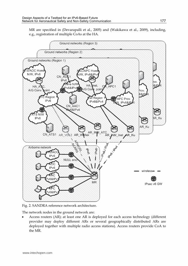
MR are specified in (Devarapalli et al., 2005) and (Wakikawa et al., 2009), including, e.g., registration of multiple CoAs at the HA.
Fig. 2. SANDRA reference network architecture.
The network nodes in the ground network are:
Access routers (AR); at least one AR is deployed for each access technology (different
provider may deploy different ARs or several geographically distributed ARs are
deployed together with multiple radio access stations). Access routers provide CoA to
the MR.
www.intechopen.com
Future Aeronautical Communications
178
Home Agents (HA); at least one HA is deployed. The functionality of the HA are again specified in (Devarapalli et al., 2005) and (Wakikawa et al., 2009). An HA further represents an air-ground routing convergence point, being aware of all routing paths (multiple CoAs) to the aircraft MR and forwarding traffic by policy routing to the MR on a particular routing path, e.g. based on QoS requirements.
IPsec gateways being the counterparts of the airborne IPsec gateways securing the ATS, AOC, AAC, and APC domains.
Correspondent Nodes (CN) in the domains ATS, AOC, AAC, APC; these are hosting the respective applications.
Depending on geographical location, the MR connects to a respective AR. ATC regional ground subnetworks are interconnected to implement global connectivity and the same holds for the Internet and its regional subnetworks. The ES (MNN and CN) are not addressed in detail in this chapter, which only deals with the IP network up to the interfaces where the ES are connected to. Although integration of legacy data links and interoperability with ACARS, ATN/OSI, IPv4 are considered essential for SANDRA (cf. Sec. 3), in the testbed the focus is on IP networking (IPv6 and IPv4). However, integration of legacy ES and applications (ACARS, ATN/OSI, analog voice) and VDL2 as access network into the testbed is currently still under investigation in terms of the details of implementation and thus not included here.
4.2 Testbed network architecture
In contrast to the reference SANDRA testbed network architecture presented in the previous
section, the actual testbed architecture and implementation will have to take into account
various constraints, such as the necessity to include IPv4 access and ground networks also
for ATS/AOC because of the current unavailability of IPv6 satellite networks.
The testbed ground-network will mainly be set-up at TriaGnoSys (TGS) premises in
Oberpfaffenhofen, Germany. Also the airborne side will initially be set-up at TGS premises
as well.
Due to limitations for the flight trials that do not apply to the laboratory set-up (e.g. no Ku-
band antenna on aircraft), only a subset of the laboratory equipment of the airborne network
will be used in the flight trials and installed in the aircraft.
Note that, as already stated above, the actual testbed network architecture will comprise
IPv4 access and ground networks between the IPv6 only ATS/AOC airborne and ground
networks due to the lack of support of IPv6 in the satellite networks available for the testbed
implementation.
In contrast to ATS/AOC, for AAC/APC the IPv4 access and ground networks are a desired element of the testbed, because support of IPv4 hosts and access networks is required for AAC/APC. In an aeronautical communication system that is deployed world-wide, MNN and MR, AR, HA, and CN are generally geographically distributed. Latencies between nodes that are close to each other are typically small, whereas latencies between nodes that are far away from each other may be significantly larger (Ayaz et al., 2009). To reflect this, the testbed ground network is separated in three regions (three regions are considered sufficient for most scenarios, e.g. that AR, HA, and CN are located in at most three different regions); latencies between nodes in the same region are small, whereas latencies between nodes in different regions may be significantly larger.
www.intechopen.com
Design Aspects of a Testbed for an IPv6-Based Future Network for Aeronautical Safety and Non-Safety Communication
179
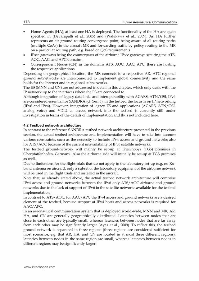
Further, it is currently not foreseen to implement separate ATC and public Internet ground networks (cf. reference network architecture from previous section). However, if later definition of use cases, scenarios, and applications, not known currently, will require this, then separate ground networks will be implemented by deployment of additional routers (possibly virtual). The resulting SANDRA testbed network architecture is shown in Fig. 3. As for NEWSKY, the mobility solution for the SANDRA testbed is NEMO (Devarapalli et al., 2005), including the possibility to register multiple Care-of-Addresses (Wakikawa et al., 2009). NEMO Route Optimisation (RO) will be considered (e.g. Global HAHA, Correspondent Router, etc.), however, implementation in the testbed will depend on an assessment of benefit and effort of the implementation, in particular if open source implementations are not yet available. Use of multiple CoAs requires synchronisation of policy routing rules at the MR and the HA. This is addressed in the recent IETF RFC 6089 (Tsirtsis et al., 2011), which also will be considered in the SANDRA testbed. Finally, NEMO Basic Mobility Support as specified in (Devarapalli et al., 2005) does not foresee IPv4 access networks. Two options allowing deployment of NEMO over IPv4 access networks will be considered for implementation in the testbed; first, RFC 5555 (Soliman, 2009) and, second, an efficient NAPT-PT based solution (Via et al., 2009) that was already successfully deployed in the NEWSKY testbed.
Fig. 3. Testbed network architecture overview, including IPv4 access and ground networks.
www.intechopen.com
Future Aeronautical Communications
180
5. Selected topics in the SANDRA testbed
In the following, we highlight a selection of topics addressed in the SANDRA testbed.
5.1 IPv6 over IPv4 network traversal
For each connected access network, the IR obtains from the IMR (or directly from a modem
in case of the fall-back solution) one or more IPv6 or IPv4 CoAs (e.g. SBB allocates an IPv4
address for each primary packet data protocol (PDP) context), which are provided by the
respective AR (by which protocol this is specifically done may depend on the IMR interface
to the IR, the specific modem, the access network etc., which are not yet defined in the
necessary detail).
In case RFC 5555 is deployed for IPv4 network traversal, IPv4 CoA are registered at the HA
via a binding update (Soliman, 2009). IPv6 packets, including NEMO signalling, are
tunnelled between MR and HA in IPv4 and a UDP header is added in case that NAT
(Network Address Translation) is present on the path.
When NeXT is deployed, traversal of the IPv4 access network for IPv6 packets is achieved
via IPv4/IPv6 translation. A context is set-up between NeXT master (in the IR) and slave
(e.g. located at the border between IPv4 Internet and IPv6 SANDRA ground networks),
mapping IPv4 CoA to an IPv6 CoA for NAPT-PT.
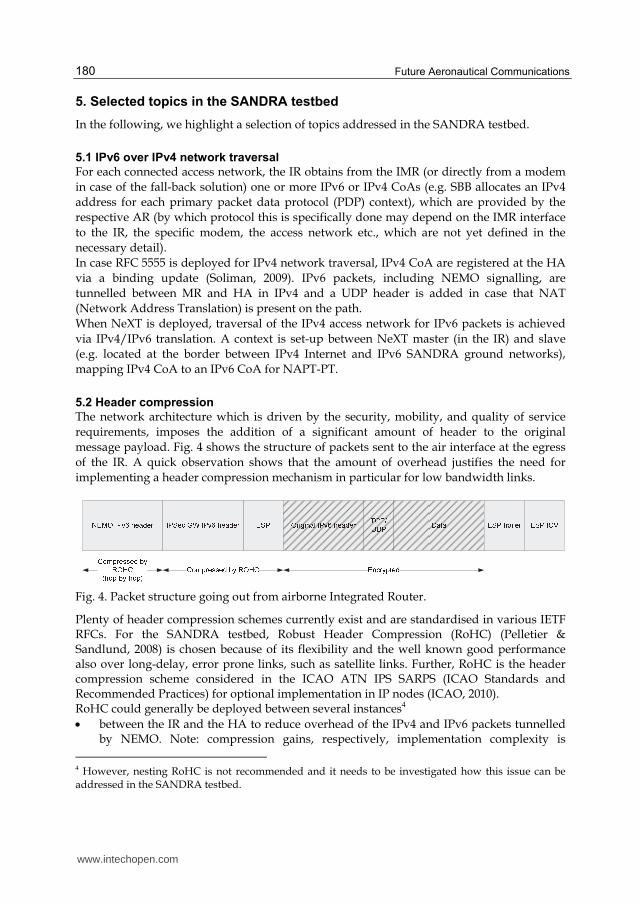
5.2 Header compression
The network architecture which is driven by the security, mobility, and quality of service
requirements, imposes the addition of a significant amount of header to the original
message payload. Fig. 4 shows the structure of packets sent to the air interface at the egress
of the IR. A quick observation shows that the amount of overhead justifies the need for
implementing a header compression mechanism in particular for low bandwidth links.
Fig. 4. Packet structure going out from airborne Integrated Router.
Plenty of header compression schemes currently exist and are standardised in various IETF RFCs. For the SANDRA testbed, Robust Header Compression (RoHC) (Pelletier & Sandlund, 2008) is chosen because of its flexibility and the well known good performance also over long-delay, error prone links, such as satellite links. Further, RoHC is the header compression scheme considered in the ICAO ATN IPS SARPS (ICAO Standards and Recommended Practices) for optional implementation in IP nodes (ICAO, 2010). RoHC could generally be deployed between several instances4
between the IR and the HA to reduce overhead of the IPv4 and IPv6 packets tunnelled by NEMO. Note: compression gains, respectively, implementation complexity is
4 However, nesting RoHC is not recommended and it needs to be investigated how this issue can be addressed in the SANDRA testbed.
www.intechopen.com

Design Aspects of a Testbed for an IPv6-Based Future Network for Aeronautical Safety and Non-Safety Communication
181
significantly affected by IPsec deployment, in particular if encryption is used (cf. next bullet)
if IPsec is deployed the relatively new RoHCoIPsec related RFCs could be implemented (Ertekin et al., 2010a, 2010b, 2010c) and deployed in the respective IPsec gateways,
between the IR and the AR, e.g. within a point-to-point protocol (PPP) context, if supported by the AR.
RoHC requires access to IP and TCP/UDP header for compressing packets. When these headers are encrypted (e.g. when using IPsec ESP) the compression is not possible. RoHC has defined a profile for ESP, but it only enables the compression of IP and the 8-Byte ESP header. Moreover, the compression works only in a hop-by-hop basis. The encrypted inner header remains untouched, as indicated in Fig. 4. A framework for integrating RoHC over IPsec (RoHCoIPsec) is defined in (Ertekin et al., 2010a). It defines the modification required in IPsec protocol stack to allow the compression of IPsec encrypted packets. Further investigations will be performed in the frame of the testbed development to assess in detail whether the expected compression gain obtained by implementing RoHCoIPSec justifies the implementation effort. Also alternatives to RoHCoIPsec will be investigated, such as Multilayer-IPsec (Zhang, 2004). Due to regulatory constraints, ANSPs (Air Navigation Service Providers) do not allow data traffic in their network to be encrypted. This puts ATS, AOC traffic in a particular situation, where IPsec with AH or ESP Null encryption could be deployed for ensuring domain separation, authenticity, and integrity of the packets, but not their confidentiality. As the inner IPv6 and transport layer header are thus unencrypted, a dedicated RoHC profile could be defined to compress all the headers except the outermost one, as it is needed for routing.
5.3 ATS and AOC data traffic Performance assessment in the testbed, not only for the assessment of RoHCoIPsec and RoHC for AH or ESP Null encryption (cf. previous section), requires realistic ATS, AOC, AAC, and APC data traffic. For ATS and AOC, the services defined in the COCR (Communications Operating Concept and Requirements for the Future Radio System) will be used (EUROCONTROL/FAA, 2007). A challenge is to obtain a communication traffic profile per aircraft (i.e. packet length, and frequency of occurrence), imposed by the COCR messages to the network. A realistic estimate needs to take into account the COCR service instance, which states, for example, that a message exchange shall take place once per sector, once per domain in airport, etc. Our COCR traffic estimate is obtained from the methodology and tool developed in the framework of the EC project ANASTASIA (Airborne New and Advanced Satellite Techniques & Technologies in A System Integrated Approach) and ESA Iris programmes. The methodology uses information from a global flight route simulation. The obtained information, e.g. average flight duration, average flight duration in a domain, etc., is used to approximate and normalise the COCR service instances, thus simplifying the complex multi-service COCR traffic. The methodology has been presented to the (satellite) ATM community several times, including EUROCONTROL and NexSAT meetings in particular, and received comments have been continuously used to improve methodology and tool. The average traffic intensity of COCR messages (in bit-per-second per aircraft) will be used, e.g. in the context of deriving RoHCoIPSec compression gain.
www.intechopen.com
Future Aeronautical Communications
182
5.4 Consideration on transport layer and IP fragmentation Some networking design aspects are also considered in the design of the SANDRA testbed. Transport layer design is currently being investigated within the SANDRA project. Basic TCP is not efficient to use due to some issues specific to the aeronautical communications: TCP slow start mechanism: TCP slow-start phase takes several RTTs to achieve the
optimum throughput. As most services require only few exchanges of small messages (some tens of kB), the available link capacity will be used inefficiently. TCP congestion control algorithm: TCP interpret segment losses as an indication of link congestion, which is usually the case in the terrestrial Internet, and immediately reduces its congestion window to reduce the network load. In wireless links bit errors may also cause segment loss, in which case reducing window size (and hence throughput) is not necessarily the most appropriate strategy. Different links with different characteristics: The variety of the link technologies also poses a challenge, because optimisation of TCP parameters with respect to one link may not be applicable to other links.
Several alternative solutions have been investigated including: Solutions to TCP slow start issue: increasing TCP Initial Window (through TCP parameters configuration), and TCP start-up optimisation mechanisms such as Jump Start, Quick Start, and Swift Start. Congestion control alternatives: TCP CUBIC, Fast-TCP, Compound TCP, and Explicit Congestion Notification (ECN). ECN extensions: eXplicit Congestion Protocol (XCP) and Rate Control Protocol (RCP).
Based on the earlier investigation within NEWSKY, two separate approaches are considered for safety and non-safety domains: an enhanced TCP solution is recommended for safety domain, and a PEP-based solution for the non-safety domain. XCP is currently considered to be an attractive TCP enhancement approach. The SANDRA testbed takes into account the transport layer issue and will implement the most appropriate solution accordingly. Another issue is related to Maximum Transmission Unit (MTU) and IP fragmentation. Although generally not considered as an issue in IPv6, IP fragmentation deserves also some consideration. In a tunnelled connection between two routers, the tunnel end points become the communication end points. RFC 2473 specifies that the routers are allowed to fragment the packets if its size is larger than the tunnel MTU (i.e. the link/path MTU minus the tunnel overhead(s)), and if the tunnel MTU is smaller than the minimum IPv6 MTU requirement (1280 Byte). One such scenario is when the IMR adds the mobility header, causing the packet size to be larger than the link MTU, e.g. satellite link, and fragments the tunnelled packet before sending it to the link. The fragmented packets can then be only reassembled at the HA. The issue of in-network reassembly then applies, e.g. the HA needs to allocate sufficient buffer to anticipate lost or out-of-order fragments, and if a fragment is lost the whole packet is considered as lost. These issues can cause a significant routing slowdown at the HA, and in turn adding up to the end-to-end latency. The SANDRA testbed will take this into account and implement the necessary solutions whenever applicable, e.g. adjusting the MTU values to allow for maximum possible packet size, or by using Path MTU Discovery (PMTUD) protocol.
6. Conclusions
This chapter has presented a detailed overview over the SANDRA testbed, including a comparison with its precursor, the NEWSKY testbed.
www.intechopen.com
Design Aspects of a Testbed for an IPv6-Based Future Network for Aeronautical Safety and Non-Safety Communication
183
It was stated that the main difference between the two testbeds is that the SANDRA testbed will represent a proof-of-principle prototype of a future aeronautical communications system, whereas the NEWSKY testbed resembled a proof-of-concept. This has quite far reaching consequences in terms of complexity of the testbed design and implementation efforts and also for verification&validation and trials, which need to be performed in a relevant environment, comprising integration on an aircraft and performing in-flight trials. In contrast to the NEWSKY proof-of-concept, the SANDRA prototype needs a high degree of automatism for QoS provision, dynamic link selection, and resource allocation, etc. These functionalities are jointly implemented in SANDRA by the Integrated Router and the Integrated Modular Radio, which both were not present in NEWSKY. Detailed design and implementation of the SANDRA testbed components including the SANDRA prototypes will continue until 2nd quarter 2012. Subsequently, all testbed components will be integrated, followed by extensive laboratory trials (until 1st quarter 2013) to verify&validate the SANDRA testbed and to investigate the performance of the deployed prototypes and protocols. After successful integration of the testbed, flight trials on an Airbus A320 will be performed in the 2nd quarter 2013 to assess performance in a real-world scenario. Of course, we intend to publish the final testbed design and trials results in future publications.
7. Acknowledgement
The research leading to these results has been partially funded by the European Community's Seventh Framework Programme (FP7/2007-2013) under Grant Agreement n° 233679. The SANDRA project is a Large Scale Integrating Project for the FP7 Topic AAT.2008.4.4.2 (Integrated approach to network centric aircraft communications for global aircraft operations). The project has 31 partners and started on 1st October 2009.
8. References
Ayaz, S.; Bauer, Chr.; Arnal, F. (2009). Minimizing End-to-End Delay in Global HAHA Networks Considering Aeronautical Scenarios, Proceedings of the 7th ACM international symposium on Mobility management and wireless access (MobiWAC ‘09), Tenerife, Canary Islands, Spain, Oct. 26-27, 2009.
Devarapalli, V.; Wakikawa, R.; Petrescu, A. & Thubert, P. (2005). Network Mobility (NEMO) Basic Support Protocol (RFC 3963), Available from:
datatracker.ietf.org/doc/rfc3963 Ertekin, E.; Jasani, R.; Christou, C. & Bormann, C. (2010a). Integration of Robust Header
Compression over IPsec Security Associations (RFC 5856), Available from: datatracker.ietf.org/doc/rfc5856
Ertekin, E.; Jasani, R.; Christou, C.; Kivinen, T. & Bormann, C. (2010b). IKEv2 Extensions to Support Robust Header Compression over IPsec (RFC 5857), Available from: datatracker.ietf.org/doc/rfc5857
Ertekin, R.; Christou, C. & Bormann, C. (2010c). IPsec Extensions to Support Robust Header Compression over IPsec (RFC 5858), Available from:
datatracker.ietf.org/doc/rfc5858
www.intechopen.com

Future Aeronautical Communications
184
EUROCONTROL/FAA (May 2007). Communications operating concept and requirements for the future radio system (COCR Version 2.0)
Fazli, E. H.; Via, A.; Duflot, S. & Werner, M. (2009). Demonstration of IPv6 Network Mobility in Aeronautical Communications Network, Proceedings of International Conference on Communications 2009 (ICC 2009), Dresden, Germany, Jun. 14-18, 2009
ICAO (2010). ICAO Doc 9896, Manual on the Aeronautical Telecommunication Network (ATN) using Internet Protocol Suite (IPS) Standards and Protocols (1st Edition), ICAO, ISBN 978-92-9231-439-2, Montréal, Quebec, Canada
Johnson, D.; Perkins, C. & Arkko, J. (2004). Mobility Support in IPv6 (RFC 3775), Available from: datatracker.ietf.org/doc/rfc3775
Nautilus project web page. (2009). 03.5.2011, Available from: www.nautilus6.org Pelletier, G. & Sandlund, K. (2008). RObust Header Compression Version 2 (RoHCv2):
Profiles for RTP, UDP, IP, ESP and UDP-Lite (RFC 5225), Available from: datatracker.ietf.org/doc/rfc5225
Perkins, C.; Johnson, D. & Arkko, J. (2011). Mobility Support in IPv6 (IETF Internet Draft), Available from: datatracker.ietf.org/doc/draft-ietf-mext-rfc3775bis
SANDRA project web page (2011). 03.5.2011, Available from: www.sandra.aero Soliman, H. (2009). Mobile IPv6 Support for Dual Stack Hosts and Routers (RFC 5555),
Available from: datatracker.ietf.org/doc/rfc5555 Tsirtsis, G.; Soliman, H.; Montavont, N.; Giaretta, G. & Kuladinithi, K. (2011). Flow Bindings
in Mobile IPv6 and Network Mobility (NEMO) Basic Support (RFC 6089), Available from: datatracker.ietf.org/doc/rfc6089
Via, A.; Fazli, E. H.; Duflot, S.; Riera, N. & Werner, M. (2009). IP Overhead Comparison in a Test-bed for Air Traffic Management Services, Proceedings of the Vehicular Technology Conference 2009 (VTC 2009), Barcelona, Spain, Apr. 26-29, 2009
Wakikawa, R.; Devarapalli, V.; Tsirtsis, G.; Ernst, T. & Nagami, K. (2009). Multiple Care-of Addresses Registration (RFC 5648), Available from: datatracker.ietf.org/doc/rfc5648
Zhang, Y. (2004). A Multilayer IP Security Protocol for TCP Performance Enhancement in Wireless Networks. IEEE Journal on Selected Areas in Communications, Vol.22, No.4, (May 2004), pp. 767-776, ISSN 0733-8716
www.intechopen.com
Future Aeronautical CommunicationsEdited by Dr. Simon Plass
ISBN 978-953-307-625-6Hard cover, 378 pagesPublisher InTechPublished online 26, September, 2011Published in print edition September, 2011
InTech EuropeUniversity Campus STeP Ri Slavka Krautzeka 83/A 51000 Rijeka, Croatia Phone: +385 (51) 770 447 Fax: +385 (51) 686 166www.intechopen.com
InTech ChinaUnit 405, Office Block, Hotel Equatorial Shanghai No.65, Yan An Road (West), Shanghai, 200040, China
Phone: +86-21-62489820 Fax: +86-21-62489821
There are well-founded concerns that current air transportation systems will not be able to cope with theirexpected growth. Current processes, procedures and technologies in aeronautical communications do notprovide the flexibility needed to meet the growing demands. Aeronautical communications is seen as a majorbottleneck stressing capacity limits in air transportation. Ongoing research projects are developing thefundamental methods, concepts and technologies for future aeronautical communications that are required toenable higher capacities in air transportation. The aim of this book is to edit the ensemble of newestcontributions and research results in the field of future aeronautical communications. The book gives thereaders the opportunity to deepen and broaden their knowledge of this field. Today’s and tomorrow’sproblems / methods in the field of aeronautical communications are treated: current trends are identified; IPv6aeronautical network aspect are covered; challenges for the satellite component are illustrated; AeroMACSand LDACS as future data links are investigated and visions for aeronautical communications are formulated.
How to referenceIn order to correctly reference this scholarly work, feel free to copy and paste the following:
Oliver Lu ̈cke and Eriza Hafid Fazli (2011). Design Aspects of a Testbed for an IPv6-Based Future Network forAeronautical Safety and Non-Safety Communication, Future Aeronautical Communications, Dr. Simon Plass(Ed.), ISBN: 978-953-307-625-6, InTech, Available from: http://www.intechopen.com/books/future-aeronautical-communications/design-aspects-of-a-testbed-for-an-ipv6-based-future-network-for-aeronautical-safety-and-non-safety-