Embed Size (px)
Citation preview
DESIGN AND TEST RESULTS OF A MICROVIBRATION IMPROVEMENT FOR AN
ANTENNA POINTING MECHANISM
Ignacio Granero Moneva (1)
, Beata Kunicka (1)
, Robert Schweikle (1)
, Matthias Oettrich (1)
, Harald Langenbach (1)
(1) Airbus Defence and Space GmbH, Claude-Dornier-Straße, 88090 Immenstaad am Bodensee, Germany.
Contact emails: [email protected] / [email protected]
ABSTRACT
The X-Band Antenna Pointing Mechanism (APM)
developed at Airbus Defence and Space Friedrichshafen
is being improved in order to meet the challenging
requirements of a current Earth Observation mission.
With the objective of reducing the microvibrations
generated by the stepper motors, a low-stiffness solution
has been implemented that decouples the big antenna
inertia from the actuators, acting like a low-pass
filtering element.
The effectiveness of the solution has been verified on a
Breadboard model, making use of a Kistler table to
measure the exported forces and torques. This paper
describes the design solution and presents the measured
test results.
1. INTRODUCTION
The Mechanisms Department at Airbus Defence and
Space in Friedrichshafen (ADSF) has developed an X-
Band Antenna Pointing Mechanism (APM) for data
downlink onboard a Low Earth Orbit (LEO) Earth
Observation (EO) Satellite.
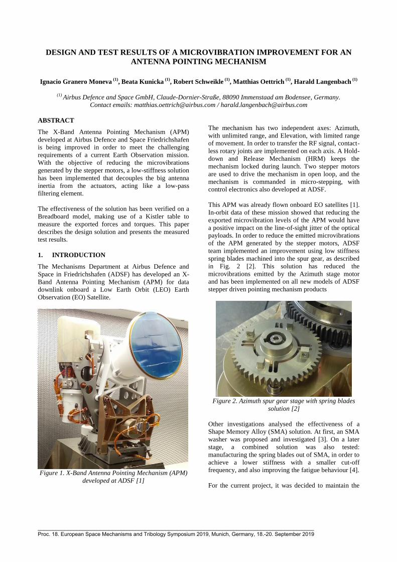
Figure 1. X-Band Antenna Pointing Mechanism (APM)
developed at ADSF [1]
The mechanism has two independent axes: Azimuth,
with unlimited range, and Elevation, with limited range
of movement. In order to transfer the RF signal, contact-
less rotary joints are implemented on each axis. A Hold-
down and Release Mechanism (HRM) keeps the
mechanism locked during launch. Two stepper motors
are used to drive the mechanism in open loop, and the
mechanism is commanded in micro-stepping, with
control electronics also developed at ADSF.
This APM was already flown onboard EO satellites [1].
In-orbit data of these mission showed that reducing the
exported microvibration levels of the APM would have
a positive impact on the line-of-sight jitter of the optical
payloads. In order to reduce the emitted microvibrations
of the APM generated by the stepper motors, ADSF
team implemented an improvement using low stiffness
spring blades machined into the spur gear, as described
in Fig. 2 [2]. This solution has reduced the
microvibrations emitted by the Azimuth stage motor
and has been implemented on all new models of ADSF
stepper driven pointing mechanism products
Figure 2. Azimuth spur gear stage with spring blades
solution [2]
Other investigations analysed the effectiveness of a
Shape Memory Alloy (SMA) solution. At first, an SMA
washer was proposed and investigated [3]. On a later
stage, a combined solution was also tested:
manufacturing the spring blades out of SMA, in order to
achieve a lower stiffness with a smaller cut-off
frequency, and also improving the fatigue behaviour [4].
For the current project, it was decided to maintain the
_____________________________________________________________________________________________ Proc. 18. European Space Mechanisms and Tribology Symposium 2019, Munich, Germany, 18.-20. September 2019
qualification status of the last flown pointing
mechanism, using the ADSF spring blades solution for
the Azimuth stage. In addition to this, a further
improvement of the microvibration emissions was
investigated, focusing on the Elevation axis and motor.
The solution investigated on the Elevation stage has the
same working principle as for the Azimuth stage. By
choosing the appropriate stiffness, it has been possible
to further improve the microvibration performance. This
paper presents the design and results of the
aforementioned investigation.
2. TARGET PERFORMANCE
The target performance is to reduce the exported forces
and torques by factor 2 at the interface of the APM to
the Spacecraft, in the frequency range 0 – 500 Hz. It
was decided to verify the improvement with on-ground
testing of the mechanism.
3. DESIGN SOLUTION
Boundary Conditions
As part of the boundary conditions, the qualification
status of the major mechanism components shall remain
unchanged, allowing only minor modifications to the
design. This drives the design of the solution.
On the one hand, only a mechanical solution is
considered, as any change in the control electronics and
operation of the stepper motor would have a high
impact on the qualification status, considering that
microstepping is already implemented in the electronics.
On the other hand, a mechanical solution shall not affect
the main load path, so that the mechanical analysis stays
applicable. Furthermore, the solution had to be passive,
as no extra control electronics could be accommodated.
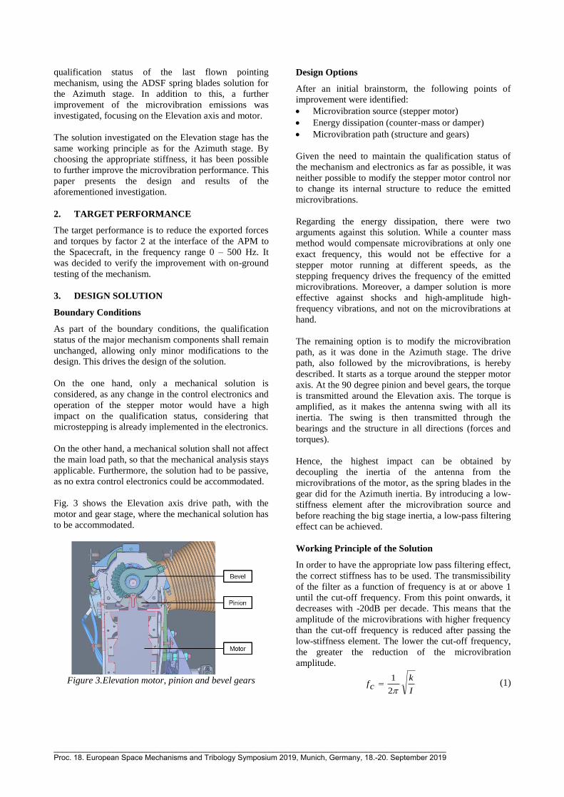
Fig. 3 shows the Elevation axis drive path, with the
motor and gear stage, where the mechanical solution has
to be accommodated.
Figure 3.Elevation motor, pinion and bevel gears
Design Options
After an initial brainstorm, the following points of
improvement were identified:
Microvibration source (stepper motor)
Energy dissipation (counter-mass or damper)
Microvibration path (structure and gears)
Given the need to maintain the qualification status of
the mechanism and electronics as far as possible, it was
neither possible to modify the stepper motor control nor
to change its internal structure to reduce the emitted
microvibrations.
Regarding the energy dissipation, there were two
arguments against this solution. While a counter mass
method would compensate microvibrations at only one
exact frequency, this would not be effective for a
stepper motor running at different speeds, as the
stepping frequency drives the frequency of the emitted
microvibrations. Moreover, a damper solution is more
effective against shocks and high-amplitude high-
frequency vibrations, and not on the microvibrations at
hand.
The remaining option is to modify the microvibration
path, as it was done in the Azimuth stage. The drive
path, also followed by the microvibrations, is hereby
described. It starts as a torque around the stepper motor
axis. At the 90 degree pinion and bevel gears, the torque
is transmitted around the Elevation axis. The torque is
amplified, as it makes the antenna swing with all its
inertia. The swing is then transmitted through the
bearings and the structure in all directions (forces and
torques).
Hence, the highest impact can be obtained by
decoupling the inertia of the antenna from the
microvibrations of the motor, as the spring blades in the
gear did for the Azimuth inertia. By introducing a low-
stiffness element after the microvibration source and
before reaching the big stage inertia, a low-pass filtering
effect can be achieved.
Working Principle of the Solution
In order to have the appropriate low pass filtering effect,
the correct stiffness has to be used. The transmissibility
of the filter as a function of frequency is at or above 1
until the cut-off frequency. From this point onwards, it
decreases with -20dB per decade. This means that the
amplitude of the microvibrations with higher frequency
than the cut-off frequency is reduced after passing the
low-stiffness element. The lower the cut-off frequency,
the greater the reduction of the microvibration
amplitude.
I
kcf
2
1 (1)
_____________________________________________________________________________________________ Proc. 18. European Space Mechanisms and Tribology Symposium 2019, Munich, Germany, 18.-20. September 2019
Eq. 1 describes the dependence of the cut-off frequency
on the stiffness and inertia (without considering
damping for simplicity). For a given inertia (I), a lower
stiffness (k) results in a lower cut-off frequency (fc). In
the project at hand, the inertia is given by the antenna
and Elevation stage design, and the modifiable variable
is the stiffness.
In terms of filtering effect, it is clear that reducing the
stiffness is beneficial. The cut-off frequency has to be
lower than the main microvibration modes. Eq. 2 can be
used to calculate the modes of the stepper motor, where
the stepping frequency (fs) is defined as a function of
the desired antenna speed (v), the stepping ratio of the
motor (sr) and the gear ratio between the antenna and
the motor (gr).
grsrvs
f (2)
Tab. 1 shows the typical values of the APM antenna
velocity and its corresponding stepping frequencies
(full-step). Notice that the harmonics of these
frequencies are also excited during the stepper motor
operation. It has been observed that the amplitude of the
microvibrations emitted is directly proportional to the
power of the motor.
Table 1. Typical antenna velocities and the
corresponding stepping frequencies for the APM
Velocity Antenna
[deg/s]
Stepping Frequency
[Hz]
0.5 22.2
1 44.4
2.5 111.1
5 222.2
10 444.4
It was calculated that for the APM a cut-off frequency
lower than 20 Hz is necessary, in order to achieve the
desired filtering effect.
Analysis of the Filter Solution
In order to have a low cut-off frequency, the stiffness
has to be low too, up to a limit. A introducing a flexible
element has structural consequences that need to be
taken into consideration:
Reduced load capability
Structural integrity of the low-stiffness blades
Pointing error
On-ground testing (1-g load case)
This means that a mid-point stiffness value can be found
on a trade-off process, achieving optimal results.
Regarding the load capability, the solution was designed
in such a way that the drive and load path are separated,
meaning that the filter will not be loaded with the
Antenna weight during the vibration test or during
launch. The vibration loads are guided through the
bearings into the structure, and not through the low-
stiffness blades.
A pointing error assessment was performed too. When
the motor creates a torque, the filter is deflected until
the torque is high enough to move the rest of the
Elevation stage and the antenna (overcoming the
friction in the bearings). Once this occurs, the filter
stays deflected during the movement, which creates a
misalignment between the motor and the antenna
pointing (this misalignment is equal to the filter’s
deflection). When the motor stops, the filter resumes its
nominal position and the antenna and motor are aligned.
In order to limit the displacement of the filter, redundant
end-stops have been implemented into the design. The
displacement has to be limited for the following
reasons:
Structural: to stay below the fatigue limit
Pointing error: to limit the offset between the
antenna and the motor.
A FEM structural analysis of the filter element was
performed, taking into account both on-ground and on-
orbit load cases. As it can be observed in Tab. 4, the
maximum displacement reached on-orbit is orders of
magnitude below the usual pointing accuracy of LEO
X-Band downlink APMs, which means that the on-orbit
pointing accuracy will not be affected by the filter.
Table 2. Results of FEM Structural Analysis of an
example Filter Solution
Load Case Max. Stress
[MPa]
Max. Displacement
[deg]
Without End-stops
On-orbit (0g) 0.08 0.0002
On-ground (1g) 403.2 1.054
With End-stops
On-orbit (0g) 0.08 0.0002
On-ground (1g) 250 0.654
Regarding the structural integrity of the filter, the end-
stops were introduced in order to limit the maximum
stress to 250MPa. With this value, the filter is fatigue
safe for the on-ground and on-orbit operation cycles.
After having seen that the load capability, the structural
integrity of the filter and the pointing error do not create
significant restrictions to the filter stiffness, the final
point to be considered is the on-ground testing. If the
filter touches the end-stops, the load path changes and
the flexible blades are not active anymore. The load
goes through the end-stops, so no filtering is achieved.
Thus, the stiffness shall be high enough to allow the
correct testing of the mechanism on ground, ensuring
that the end-stops are not touched.
_____________________________________________________________________________________________ Proc. 18. European Space Mechanisms and Tribology Symposium 2019, Munich, Germany, 18.-20. September 2019
With this in mind, a breadboard was built and the
following filters were tested:
Low-stiffness filter
High-stiffness filter
No Filter (for comparison)
Both filter solutions tested (low and high stiffness) had
a cut-off frequency of 20 Hz and below this value,
respectively.
4. BREADBOARD TESTING
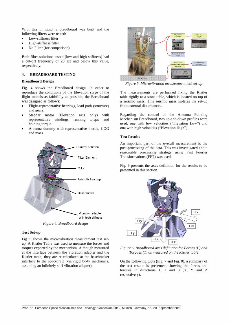
Breadboard Design
Fig. 4 shows the Breadboard design. In order to
reproduce the conditions of the Elevation stage of the
flight models as faithfully as possible, the Breadboard
was designed as follows:
Flight-representative bearings, load path (structure)
and gears.
Stepper motor (Elevation axis only) with
representative windings, running torque and
holding torque.
Antenna dummy with representative inertia, COG
and mass.
Figure 4. Breadboard design
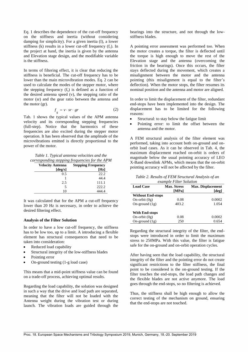
Test Set-up
Fig. 5 shows the microvibration measurement test set-
up. A Kistler Table was used to measure the forces and
torques exported by the mechanism. Although measured
at the interface between the vibration adapter and the
Kistler table, they are re-calculated at the basebracket
interface to the spacecraft (via rigid body mechanics,
assuming an infinitely stiff vibration adapter).
Figure 5. Microvibration measurement test set-up
The measurements are performed fixing the Kistler
table rigidly to a stone table, which is located on top of
a seismic mass. This seismic mass isolates the set-up
from external disturbances.
Regarding the control of the Antenna Pointing
Mechanism Breadboard, two up-and-down profiles were
used, one with low velocities (“Elevation Low”) and
one with high velocities (“Elevation High”).
Test Results
An important part of the overall measurement is the
post-processing of the data. This was investigated and a
reasonable processing strategy using Fast Fourier
Transformations (FFT) was used.
Fig. 6 presents the axes definition for the results to be
presented in this section.
Figure 6. Breadboard axes definition for Forces (F) and
Torques (T) as measured on the Kistler table
On the following plots (Fig. 7 and Fig. 8), a summary of
the test results is presented, showing the forces and
torques in directions 1, 2 and 3 (X, Y and Z
respectively).
_____________________________________________________________________________________________ Proc. 18. European Space Mechanisms and Tribology Symposium 2019, Munich, Germany, 18.-20. September 2019
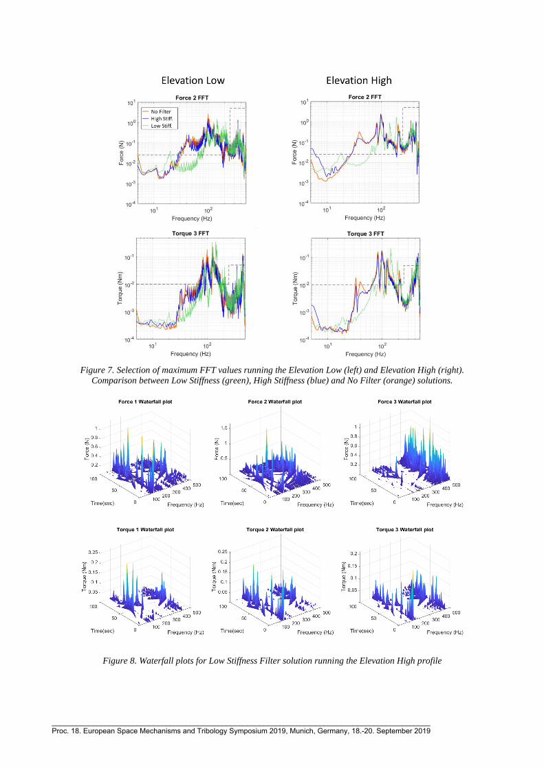
Figure 7. Selection of maximum FFT values running the Elevation Low (left) and Elevation High (right).
Comparison between Low Stiffness (green), High Stiffness (blue) and No Filter (orange) solutions.
Figure 8. Waterfall plots for Low Stiffness Filter solution running the Elevation High profile
_____________________________________________________________________________________________ Proc. 18. European Space Mechanisms and Tribology Symposium 2019, Munich, Germany, 18.-20. September 2019
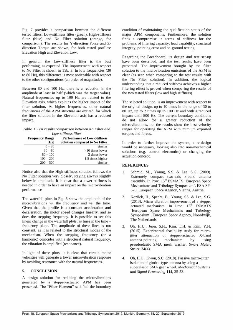
Fig. 7 provides a comparison between the different
tested filters: Low-stiffness filter (green), High-stiffness
filter (blue) and No Filter solution (orange, for
comparison). The results for Y-direction Force and Z-
direction Torque are shown, for both tested profiles:
Elevation High and Elevation Low.
In general, the Low-stiffness filter is the best
performing, as expected. The improvement with respect
to No Filter is shown in Tab. 3. In low frequencies (30
to 80 Hz), this difference is most noticeable with respect
to the other configurations (an order of magnitude).
Between 80 and 100 Hz, there is a reduction in the
amplitude at least in half (which was the target value).
Natural frequencies up to 100 Hz are related to the
Elevation axis, which explains the higher impact of the
filter solution. At higher frequencies, other natural
frequencies of the APM structure are excited, for which
the filter solution in the Elevation axis has a reduced
impact.
Table 3. Test results comparison between No Filter and
Low-stiffness filter
Frequency Range
[Hz]
Performance of Low-Stiffness
Solution compared to No Filter
0 – 30 similar
30 – 80 >10 times lower
80 – 100 2 times lower
100 – 200 1.5 times higher
200 – 500 similar
Notice also that the High-stiffness solution follows the
No Filter solution very closely, staying always slightly
below in amplitude. It is clear that a lower stiffness is
needed in order to have an impact on the microvibration
performance
The waterfall plots in Fig. 8 show the amplitude of the
microvibrations vs. the frequency and vs. the time.
Given that the profile is a constant acceleration and
deceleration, the motor speed changes linearly, and so
does the stepping frequency. It is possible to see this
linear change in the waterfall plots, as lines in the time –
frequency plane. The amplitude of these lines is not
constant, as it is related to the structural modes of the
mechanism. When the stepping frequency (or a
harmonic) coincides with a structural natural frequency,
the vibration is amplified (resonance).
In light of these plots, it is clear that certain motor
velocities will generate a lower microvibration response
by avoiding resonance with the natural frequencies.
5. CONCLUSION
A design solution for reducing the microvibrations
generated by a stepper-actuated APM has been
presented. The “Filter Element” satisfied the boundary
condition of maintaining the qualification status of the
major APM components. Furthermore, the solution
finds a compromise in terms of stiffness for the
problems of filtering capacity, load capability, structural
integrity, pointing error and on-ground testing.
Regarding the Breadboard, its design and test set-up
have been described, and the test results have been
presented. The improvement brought by the filter
solution to the microvibration emissions of the APM is
clear (as seen when comparing to the test results with
the No Filter solution). In addition, the logical
understanding that a reduced stiffness achieves a higher
filtering effect is proved when comparing the results of
the two tested filters (low and high stiffness).
The selected solution is an improvement with respect to
the original design, up to 10 times in the range of 30 to
80 Hz, up to 2 times up to 100 Hz and with a reduced
impact until 500 Hz. The current boundary conditions
do not allow for a greater reduction of the
microvibrations, but the results show the best velocity
ranges for operating the APM with mimium exported
torques and forces.
In order to further improve the system, a re-design
would be necessary, looking also into non-mechanical
solutions (e.g. control electronics) or changing the
actuation concept.
REFERENCES
1. Schmid, M.., Young, S.S. & Lee, S.G. (2009).
Extremely compact two-axis x-band antenna
assembly. In Proc. 15th
ESMATS ‘European Space
Mechanisms and Tribology Symposium’, ESA SP-
670, European Space Agency, Vienna, Austria.
2. Kozilek, H., Specht, B., Young, SS. & Lee, S.G.
(2013). Micro vibration improvement of a stepper
actuated mechanism. In Proc. 13th
ESMATS
‘European Space Mechanisms and Tribology
Symposium’, European Space Agency, Noordwijk,
The Netherlands.
3. Oh, H:U., Jeon, S.H., Kim, T.H. & Kim, Y.H.
(2015). Experimental feasibility study for micro-
jitter attenuation of stepper-actuated X-band
antenna-pointing mechanism by using
pseudoelastic SMA mesh washer. Smart Mater.
Struct. 24(4).
4. Oh, H.U., Kwon, S.C. (2018). Passive micro-jitter
isolation of gimbal-type antenna by using a
superelastic SMA gear wheel. Mechanical Systems
and Signal Processing 114, 35-53.
_____________________________________________________________________________________________ Proc. 18. European Space Mechanisms and Tribology Symposium 2019, Munich, Germany, 18.-20. September 2019