Embed Size (px)
Citation preview
University of North DakotaUND Scholarly Commons
Theses and Dissertations Theses, Dissertations, and Senior Projects
January 2016
Design And Implementation Of Co-OperativeControl Strategy For Hybrid AC/DC MicrogridsRasel Mahmud
Follow this and additional works at: https://commons.und.edu/theses
This Thesis is brought to you for free and open access by the Theses, Dissertations, and Senior Projects at UND Scholarly Commons. It has beenaccepted for inclusion in Theses and Dissertations by an authorized administrator of UND Scholarly Commons. For more information, please [email protected].
Recommended CitationMahmud, Rasel, "Design And Implementation Of Co-Operative Control Strategy For Hybrid AC/DC Microgrids" (2016). Theses andDissertations. 2041.https://commons.und.edu/theses/2041
DESIGN AND IMPLEMENTATION OF CO-OPERATIVE CONTROL
STRATEGY FOR HYBRID AC/DC MICROGRIDS
by
Rasel Mahmud
A Thesis
Submitted to the Graduate Faculty
of the
University of North Dakota
in partial fulfillment of the requirements
for the degree of
Master of Science
Grand Forks, North Dakota
August
2016

PERMISSION
Title Design and implementation of co-operative control strategy for hybrid AC/DC microgrids
Department Electrical Engineering
Degree Master of Science
In presenting this thesis in partial fulfillment of the requirements for a graduate degree from the University of North Dakota, I agree that the library of this University shall make it freely available for inspection. I further agree that permission for extensive copying for scholarly purposes may be granted by the professor who supervised my thesis work or, in his absence, by the chairperson of the department or the dean of the Graduate School. It is understood that any copying or publication or other use of this thesis or part thereof for financial gain shall not be allowed without my written permission. It is also understood that due recognition shall be given to me and to the University of North Dakota in any scholarly use which may be made of any material in my thesis.
Signature
Date c-.r /'2 vj·.J cl£
lll
iv
TABLE OF CONTENTS
LIST OF FIGURES………………………………………………………………VIII
ACKNOWLEDGEMENTS ....................................................................................... XI
ABSTRACT ............................................................................................................. XV
CHAPTER
1. INTRODUCTION...................................................................................................... 1
1.1 Research Objectives and Methodology ......................................................... 2
1.2 Outline of the Thesis ...................................................................................... 4
2. LITERATURE REVIEW ............................................................................................ 7
2.1 Overview ........................................................................................................ 7
2.2 Microgrid operation and control ................................................................... 7
2.2.1 DC microgrid with PEV ......................................................................... 7
2.2.2 Islanded mode of operation of AC microgrid ....................................... 10
2.2.3 Power management of hybrid AC/DC microgrid ................................. 12
2.3 Microgrid laboratory prototype development ............................................. 13
3. DC MICROGRID WITH PEV .................................................................................. 16
3.1 Overview ...................................................................................................... 16
v
3.2 SoC Based Distributed Co-operative Control ............................................. 17
3.2.1 Description of the microgrid ................................................................. 17
3.2.2 Background on graph theory ................................................................ 18
3.2.3 Distributed Co-operative Control (DCC) ............................................. 19
3.2.4 SoC based Distributed Co-operative Control for PEV charging and
discharging ............................................................................................................ 21
3.2.5 Distributed Energy Management System (EMS) ................................. 25
3.3 Case Studies ................................................................................................. 27
3.3.1 All the PEVs are discharging ................................................................ 28
3.3.2 All the PEVs are charging while DGs are supplying demand .............. 29
3.3.3 Transient performance of the proposed method ................................... 31
3.3.4 Performance of the control scheme under varying load ....................... 31
3.3.5 Performance comparison between droop control and DCC ................. 32
3.4 Conclusion ................................................................................................... 34
4. CONTROL OF AC MICROGRID IN ISLANDED MODE OF OPERATION ....................... 35
4.1 Overview ...................................................................................................... 35
4.2 Dynamic Model of Inverter based DGs ....................................................... 35
4.3 Beyond droop control .................................................................................. 44
4.3.1 Distributed co-operative control (DCC) for AC microgrid: ................. 45
vi
5. CO-OPERATIVE CONTROL FOR AC/DC HYBRID MICROGRID ................................ 50
5.1 Overview ...................................................................................................... 50
5.2 Hybrid microgrid architecture and mode of operations.............................. 51
5.2.1 Grid-connected mode of operation for hybrid microgrid: .................... 51
5.2.2 Islanded mode of operation for hybrid microgrid: ............................... 53
5.2.3 Proposed DCC for hybrid AC/DC microgrid ....................................... 55
5.3 Simulation results: ....................................................................................... 59
5.3.1 Case 1: .................................................................................................. 60
5.3.2 Case 2 .................................................................................................... 62
6. MICROGRID LABORATORY PROTOTYPE .............................................................. 65
6.1 Overview ...................................................................................................... 65
6.2 Overview of the components in the PERL-Microgrid (P-MG) .................... 66
6.2.1 Renewable energy source models: ........................................................ 68
6.2.2 Photovoltaics (PV) simulator ................................................................ 69
6.2.3 Energy storage systems (ESS) simulator .............................................. 70
6.2.4 Fuel Cell system emulator: ................................................................... 71
6.2.5 Wind energy system simulator and grid simulator ............................... 71
6.3 Power electronic Converter ......................................................................... 72
6.4 Filters ........................................................................................................... 74
vii
6.5 Microgrid distribution network model......................................................... 76
6.6 Load model .................................................................................................. 77
6.7 Real-time data communication control platform ......................................... 79
6.8 Microgrid software architecture.................................................................. 80
6.9 Microgrid Power Network architecture ...................................................... 82
6.10 Microgrid control architecture .................................................................. 84
6.10.1 Control of the converters .................................................................... 84
6.10.2 Control of the Microgrid ..................................................................... 85
6.10.3 Phase-locked-loop (PLL) and Synchronization .................................. 86
7. EXPERIMENTAL VERIFICATION ........................................................................... 90
7.1 Case 1: System start-up and steady-state operation.................................... 91
7.2 Case 2: Change of load share .................................................................... 93
7.3 Case 3: Load dynamics ................................................................................ 94
7.4 Case 4: De-synchronization of the DGs ...................................................... 96
7.5 Case 5: Power network topology Reconfiguration ...................................... 98
8. FUTURE WORK AND CONCLUSION ..................................................................... 100
Future Work: ................................................................................................... 100
Conclusion ....................................................................................................... 103
REFERENCES ........................................................................................................ 104
viii
LIST OF FIGURES
Figure Page
3.1 DC microgrid System layout with PEVs ..............................................................17
3.2 Communication network layout over physical network .......................................19
3.3 Rate of change of SoC decreases as per unit current (Ipu) increases ..................25
3.4 Charging/discharging decision flowchart for PEV ..............................................26
3.5 Simulink model of the DC microgrid ...................................................................27
3.6 Both of the PEVs are discharging. a) Voltage profile b) Load sharing among
the DGs and the PEVs c) SoC of the PEV batteries. ............................................29
3.7 Both of the PEVs are charging a) Voltage profile b) Load sharing among the
DGs and the PEVs charging currents c) SoC of the PEV batteries. .....................30
3.8 Transient performance of the proposed method when both of the PEVs were
switched from discharging mode to charging. .....................................................31
3.9 Transient performance of the control scheme under varying load when both
of the PEVs are discharging a) Voltage profile b) Load sharing among the
DGs and the PEVs. ...............................................................................................32
3.10 Performance comparison between droop control and DCC .................................33
4.1 Control of three-phase inverter .............................................................................36
4.2 Control block diagram of VSC voltage control, a) Voltage controller, b)
Current controller .................................................................................................37
4.3 Schematic diagram of an AC microgrid ...............................................................39
4.4 Frequency vs real power droop ............................................................................41
4.5 Voltage vs reactive power Droop .........................................................................42

ix
4.6 Simulink model of the AC microgrid ...................................................................42
4.7 Performance of droop control a) Voltage profile b) frequency c) real power
sharing, and d) reactive power sharing .................................................................44
4.8 Control block and communication graph for DCC of AC microgrid ...................46
4.9 Performance of DCC a) Voltage profile b) frequency c) real power sharing d)
reactive power sharing ..........................................................................................48
5.1 Structure of the AC/DC hybrid microgrid ............................................................52
5.2 Communication graph for DCC of hybrid AC/DC microgrid .............................56
5.3 Calculation of second correction factor ................................................................58
5.4 Simulink model of the AC/DC hybrid microgrid .................................................59
5.5 Performance of the controller under the condition of fixed scheduled power
through the IC .......................................................................................................62
5.6 Performance of the controller to share the load among the DGs in a hybrid
microgrid according to the power rating ..............................................................64
6.1 Hardware side of AC microgrid in the P-MG showing the inverters, filters,
lines and power sources. The controller computers are located on the other
side. .......................................................................................................................67
6. 2 P-MG DC microgrid showing the interfacing converter, DC-DC converter
and the dSPACE to control the DC microgrid .....................................................67
6.3 Semikron AC-DC converter used in P-MG and its internal power stage a)
Semikron converter with custom built gate-drive circuit, b) diode-rectifier
and DC-AC converter power stage ......................................................................73
6.4 Gate drive signal amplifier circuit for the Semikron inverters .............................73
6.5 LCL filter used in P_MG a) close view of the filter built at P-MG b)
Frequency response of the filter. ..........................................................................75
6.6 The distribution lines built for P-MG following pi-model. The top box
contains a line model and the bottom box contains the fuses and
electromagnetic relays for protection. ..................................................................77
x
6.7 Active and passive loads used in P-MG. a) Chroma AC/DC Electronic Load
(model 63803) b) Chroma High Power DC Electronic Load (model 63203)
c) induction motor-generator set d) BK precision DC electronic load
(MDL305) e) three-phase resistive load bank f) lighting load bank ....................78
6.8 Real-time data communication for control and monitoring using dSPACE
ds1103. .................................................................................................................80
6.9 Software platforms used in P-MG to developed different application software ..82
6.10 A typical multi-bus power architecture of P-MG with different DGs and
loads connected at different buses. .......................................................................83
6.11 Running average filter (RAF) based enhanced PLL (E-PLL) ..............................87
6.12 Details of the synchronization scheme used in P-MG a) shows the
information flow from and to different blocks in the synchronization scheme
b) voltage, frequency and phase angle adjustment approach used in the
synchronizer .........................................................................................................88
7.1 Experimental topology ........................................................................................91
7.2 Start-up of the DGs and synchronization of the DGs in the Microgrid ..............92
7.3 Effect of changing the droop parameters ............................................................94
7.4 Repetitive Load change effects on the microgrid operation ...............................95
7.5 De-synchronization of the DGs in P-MG ...........................................................97
7.6 Change of current through line 4 for the change of network topology. ..............99

xi
ACKNOWLEDGEMENTS
I would like to thank my thesis advisor, Dr. Arash Nejadpak, for his guidance,
generous support, and patience over the course of the last two years. I would also like to
thank Dr. Hossein Salehfer, Dr. Reza Fazel-Rezai, Dr. Prakash Ranganathan and Dr. Ali
Sarikhani for serving as my thesis committee members.
Special thanks to my wife, parents, sister and brother for their continuous support
patience, and encouragement.
xii
ABBREVIATIONS
AC Alternating Current
ADC Analog-to-digital converter
CSI Current source inverters
DC Direct Current
DCC Distributed cooperative control
DER Distributed energy resource
DG Distributed generator
DNO Distribution Network Operator
DR Demand Response
ECU Electronic control unit
EMS Energy management system
EPLL Enhanced phase-locked-loop
EPS Electric power system
ESS Energy storage systems
GUI Graphical user interface
IC Interfacing converter
MAS Multi Agent System
xiii
MPPT Maximum Power Point Tracking
PCC Point of common coupling
PERL Power Electronics Research Laboratory
PEV Plug-in-electric-vehicle
PHIL Power hardware-in-the-loop
PI Proportional-Integral
PLL Phase-locked-loop
P-MG PERL Microgrid
PSC Post synchronization controller
PV Photo-voltaic
PWM Pulse-width-modulation
RAF Running average filter
RES Renewable energy source
SITL System-in-the-loop
SoC State-of-charge
STS Static transfer switch
SU Synchronizer unit
VSC Voltage source converter

xiv
VSI Voltage source converters
xv
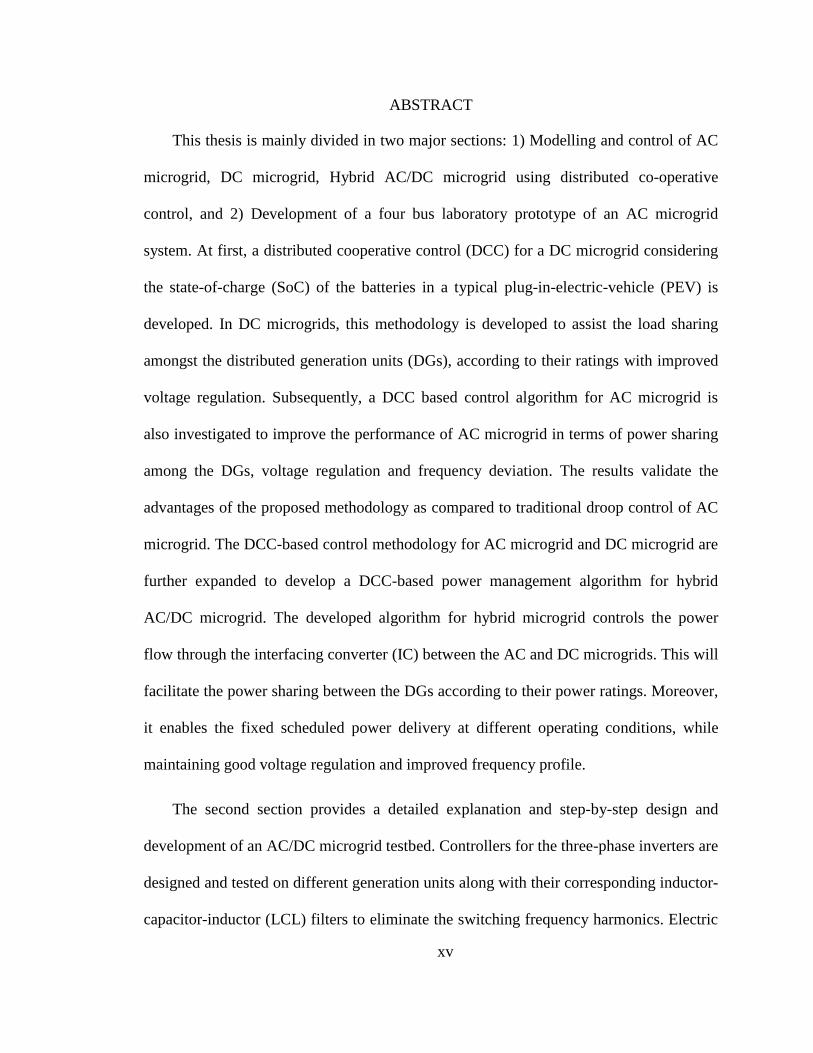
ABSTRACT
This thesis is mainly divided in two major sections: 1) Modelling and control of AC
microgrid, DC microgrid, Hybrid AC/DC microgrid using distributed co-operative
control, and 2) Development of a four bus laboratory prototype of an AC microgrid
system. At first, a distributed cooperative control (DCC) for a DC microgrid considering
the state-of-charge (SoC) of the batteries in a typical plug-in-electric-vehicle (PEV) is
developed. In DC microgrids, this methodology is developed to assist the load sharing
amongst the distributed generation units (DGs), according to their ratings with improved
voltage regulation. Subsequently, a DCC based control algorithm for AC microgrid is
also investigated to improve the performance of AC microgrid in terms of power sharing
among the DGs, voltage regulation and frequency deviation. The results validate the
advantages of the proposed methodology as compared to traditional droop control of AC
microgrid. The DCC-based control methodology for AC microgrid and DC microgrid are
further expanded to develop a DCC-based power management algorithm for hybrid
AC/DC microgrid. The developed algorithm for hybrid microgrid controls the power
flow through the interfacing converter (IC) between the AC and DC microgrids. This will
facilitate the power sharing between the DGs according to their power ratings. Moreover,
it enables the fixed scheduled power delivery at different operating conditions, while
maintaining good voltage regulation and improved frequency profile.
The second section provides a detailed explanation and step-by-step design and
development of an AC/DC microgrid testbed. Controllers for the three-phase inverters are
designed and tested on different generation units along with their corresponding inductor-
capacitor-inductor (LCL) filters to eliminate the switching frequency harmonics. Electric
xvi
power distribution line models are developed to form the microgrid network topology.
Voltage and current sensors are placed in the proper positions to achieve a full visibility
over the microgrid. A running average filter (RAF) based enhanced phase-locked-loop
(EPLL) is designed and implemented to extract frequency and phase angle information.
A PLL-based synchronizing scheme is also developed to synchronize the DGs to the
microgrid. The developed laboratory prototype runs on dSpace platform for real time data
acquisition, communication and controller implementation.
1
Chapter 1
Introduction
A microgrid is a small scale electrical power distribution network which includes a
number of distributed generations (DGs), energy storage systems (ESS) serving the local
loads. The microgrid can be operated in grid-tied mode or islanded mode depending on
the emergency conditions or the planned islanding of the microgrid. Examples of
microgrid applications are university campuses, remote island communities, residential
complexes, and industrial or commercial facilities. Microgrids are ideal candidates for
integrating renewable energy sources (RES) and DGs in power distribution network by
minimizing the impact of the stochastic nature of DGs and RESs, such as photovoltaic,
and wind energy through effective control strategies [1]-[2]. Other pertinent benefits of
the microgrids are reduced transmission and distribution costs, greater reliability, and
lower energy losses. Several advantages of DC microgrids over AC microgrids have been
reported in the literature in terms of power availability [3]-[4], and loss reduction [5].
Issues of AC power systems such as synchronizations, reactive power flow, and
frequency control are not present in DC microgrids [6]. However, AC power systems
have matured protection system and standards which DC microgrids lack [7]. In order to
take advantage of both of the systems, hybrid microgrids, combining AC and DC
microgrids, have been proposed in many research papers [8]–[11].
2
The presence of different energy sources and ESS with diverse dynamic properties
with varied electrical and mechanical properties in microgrids has raised the concerns of
safety, efficiency and stability of the system. The operation and control of microgrids
become more crucial in islanded mode of operation when there is no support from the
utility. The concentration of this work includes the islanded mode of operation and
control of AC microgrid, DC microgrid, hybrid AC/DC microgrid and development of a
microgrid laboratory prototype testbed.
1.1 Research Objectives and Methodology
This thesis examines the modeling and designing the control of AC/DC microgrids.
This work investigates the possibility of improving the voltage profile of both for AC and
DC microgrids and the frequency profile (AC microgrid) in steady-state islanded mode of
operation while providing accurate control over the power sharing among the DGs
connected to the microgrids. The operation of microgrids is further explored in this thesis
by developing a laboratory prototype of AC/DC microgrid testbed.
The first objective of this thesis is to investigate the operation of a DC microgrid
comprising several DGs connected to the system through DC-DC converters. The
conventional method of DC microgrid operation is droop-based where output voltage of
each of the DC-DC converters is proportional to the output power of the converter.
Though this approach is very simple in operation, the voltage regulation of the microgrid
is very poor and power sharing among the converters is not accurate if droop-based
control is employed. In order to overcome these issues, a distributed co-operative control
3
(DCC) strategy is proposed and developed where each DC-DC converter is provided with
information from its neighboring converters to improve and properly regulate its output
voltage. Specifically, the proposed DCC augments the droop-based control by using the
information from the neighboring DGs to improve the voltage regulation of the microgrid
and provides accurate power sharing between the converters. The operation of the
proposed DCC strategy is extended to include the dynamic behavior of battery charging
and discharging of plug-in-electric–vehicles (PEVs). A distributed energy management
system (EMS) is also developed for the charging/discharging of PEVs in a DC microgrid.
Currently droop-based control is also mostly used to control the voltage and
frequency of the AC microgrids in islanded mode of operation. However, droop
controlled AC microgrids also suffer from problems, including poor voltage regulation,
large deviation of frequency from nominal value, and poor real power and reactive power
sharing. To address these issues, a DCC strategy for the AC microgrid is also investigated
in this thesis. Using an estimated average voltage value, delivered real power and reactive
power normalized with respect to rated values from the neighboring DGs in an AC
microgrid, the controller updates the reference values of voltage and frequency of its own
DG to achieve good voltage and frequency profiles while maintaining accurate real
power and reactive power sharing.
Hybrid AC/DC microgrids will be the most efficient way to integrate DC and AC
energy sources/load in future smart grid architecture. Though power management of
individual AC microgrids and DC microgrids has been extensively studied, power
management of hybrid AC/DC microgrids has not yet received that much of attention.As
4
such different modes of operation of AC/DC hybrid microgrids, and power management
control strategies for hybrid microgrids using DCC are also investigated in this thesis.
Most of the power management strategies for hybrid AC/DC microgrids found in the
literature are droop based which exhibit the inherent problems of droop-based controls
such as poor voltage regulation and inaccurate power sharing. A DCC-based power
management scheme for hybrid microgrid under different mode of operation is proposed
and developed in this thesis.
Power electronic interfaced DGs are the main constituents of AC microgrids. That is
why the operation and control strategies for AC microgrids are not the same as the
conventional AC power systems. Before the control methods are implemented in a real
microgrid serving critical loads, they have to be first tested in laboratory based microgrid
prototypes in order to ensure their reliability and dependability. One of the major
objectives of this thesis is to design and develop a four-bus AC/DC microgrid testbed.
Each of the hardware, software, and communication components of the laboratory
prototype are designed, built, analyzed, verified and implemented at the Power
Electronics Research Laboratory (PERL) at University of North Dakota. Finally, the
microgrid testbed is tested under different network topologies and load variations for
dynamic and steady-state performance evaluation purposes.
1.2 Outline of the Thesis
The contents of the remaining chapters of the thesis are briefly discussed in this
section.
5
Chapter 2 provides the literature survey on microgrid that are relevant to the
investigations carried out in this thesis. The literature survey is broken down into four
groups discussing previous works, developments and researches on control strategy for
DC microgrids, AC microgrids in islanded mode of operation, control strategy for
AC/DC hybrid microgrid power management, and microgrid laboratory prototype
developments.
Chapter 3 briefly discusses graph theory which provides the basic mathematical
foundation for the DCC based control strategy. The communication graph required for
implementing the proposed DCC for DC microgrid is presented in this chapter. Using
this communication graph, the development of DCC for DC microgrid is discussed in the
next section. Using an optimum control strategy, the State-of-Charge (SoC) of the
batteries of PEVs connected to the DC microgrid is analyzed. Furthermore, an energy
management system (EMS) for the DC microgrid with PEVs is also presented. The
chapter finally includes simulation results to verify the effectiveness of the developed
SoC based DCC for the DC microgrid.
Chapter 4 starts with a detailed mathematical model of the AC microgrid and lays
the foundation for development of the DCC for AC microgrid. Using the graph theory
presented in chapter 3, a communication graph for AC microgrid is developed. DCC for
AC microgrid is developed where voltage and frequency references are updated by
employing the communication graph for information sharing from neighboring DGs. The
performance improvement in terms of voltage profile, frequency profile, and power
sharing are demonstrated through simulation at the end of this chapter.
6
Chapter 5 discusses the different mode of operation and power management
strategies for hybrid AC/DC microgrid. The DCC strategy developed for AC and DC
microgrids in the previous chapters are investigated to achieve power flow control in
AC/DC hybrid microgrids. A DCC based power management control strategy is proposed
in this chapter for hybrid AC/DC microgrids. The proposed method is verified through
simulation under different operating conditions at the end of this chapter.
Chapter 6 presents the design, development, validation and operation of the
microgrid laboratory testbed at PERL, UND. The chapter first elaborates on the design
procedures of hardware components such as power supplies, power electronic converters,
filters, distribution line models, load models, and the real-time data communication
platform used in the laboratory testbed. It then discusses the microgrid software
architecture, microgrid power network architecture and microgrid control architecture.
Design of the phase-locked-loop (PLL) used for synchronization and inverter control is
discussed in this chapter.
Chapter 7 analyzes the experimental data obtained from the laboratory testbed under
varying load conditions and topology changes.
Chapter 8 concludes the thesis with an overall discussion about the methods and
results obtained through simulations and experiments. This chapter also recommends
some future research areas on microgrids that can improve the works done so far at the
PERL, UND.
7
Chapter 2
Literature Review
2.1 Overview
The literatures reviews on microgrids operation, control, and prototype development
surveyed during this thesis are briefly discussed in this chapter.
2.2 Microgrid operation and control
2.2.1 DC microgrid with PEV
Plug-in-electric-vehicles (PEVs), with their batteries, can store energy, making them
one of the most common sources of distributed energy storage. In distributed storage,
PEVs have the potentials to participate in both net metering or “vehicle-to-grid” (V2G)
energy outflows, and demand response programs. With the introduction of Distributed
Generation (DG) sources, microgrids are becoming a key concept in accommodation of
these DGs and energy storage systems [12]. Microgrids are small scale power systems
with generation, consumption, and storage all placed in a close physical vicinity [13]. To
supply different kind of loads from renewable energy sources, it is necessary to have
multiple AC-DC and DC-AC conversions which cause a significant energy wastage
before end use [14]. Considering the fact that many of the emerging Renewable Energy
Sources (RES), e.g., solar photovoltaics, fuel cells, and energy storage units, e.g.,
8
batteries, hydrolysers, and ultra-capacitors, produce DC power, DC microgrids have been
suggested to reduce cost and avoid redundant conversion stages [12]-[13], [15]. Aside
from the great popularity of DC microgrids, the rapid development of Plug-in-Electric-
Vehicle (PEV) technology is attracting much attention both in industrial and academic
field [16]. In recent years, penetration of PEVs in the market has increased dramatically
[17]. However, uncoordinated charging of these PEVs may have serious negative
impacts, both technical and economical, on the Grid [18]-[19]. As distributed energy
storage units, the batteries of PEVs can offer an attractive solution to the intermittent and
random nature of the RESs. PEVs can also contribute significantly to the power flow
controls, energy management, and maintaining power quality if the charging/discharging
of PEV batteries are properly captured and coordinated [20].
A composite DC microgrid system may be connected to a number of DGs, ESSs, and
other resources such as solar photovoltaic units, fuel cells, and PEVs along with local
loads. Similar to the control of AC microgrids, hierarchical controls DC microgrid can be
adopted with three layers of control, namely primary control, secondary control and
tertiary control [12]-[13], [15], [21]. In the primary control, a virtual output-impedance
regulates the converter output voltages to reduce the circulating current among parallel
converters and reduces the difference between the scheduled power and the actual
instantaneous actual power delivered by the converters. One of the drawbacks of primary
control or droop control is that it has a poor voltage regulation, i.e., the converter output
voltage deviates from the reference voltage. To compensate for this voltage deviation, a
secondary controller restores the voltage of the converter to its reference level. The
tertiary control regulates the power flow between the DC microgrid with other networks,
9
such as, AC/DC distribution networks or AC/DC microgrids. The overall objectives of
the hierarchical control are to ensure good voltage regulation and proportional load
sharing (in per unit) among the converters.
Secondary and tertiary control of DC microgrids can be further categorized into two
classes, centralized control structures [22], [23], [24] and decentralized control structures
[25]. An energy control center (ECC) regulates the microgrid terminals using extensive
communications in the centralized control structure. This type of system suffers heavily
from reliability and scalability issues because a single communication link failure may
result in the disruption of the microgrid operation. Decentralized control architecture
itself may be of two forms, 1) local controller where only local information are used [26],
and 2) distributed controller [27] where information from neighboring terminals are used
to reach a global consensus which then eliminates the requirement of extensive
communications between the central controller and microgrid terminals.
A fuzzy logic power flow controller was used in [19] to control the
charging/discharging of PEV batteries in a workplace parking garage within a DC
distribution system. Variations of DC link voltage in Photovoltaic (PV) generation
systems was used in [28] to develop a smart PEV charging controller. However, both of
these controllers are designed assuming grid connection and do not consider isolated
microgrid operations. Using radial basis function network (RBFN) technique for
forecasting PV generation, and Genetic Algorithm (GA) for the solution of optimization
problem, a method for optimal integration of PEVs in microgrids was proposed in [20].
But this method requires a centralized control for Distribution Network Operators
10
(DNOs). A distributed optimal charging rate control method of PEVs using Multi Agent
System (MAS)-based framework and consensus algorithm was presented in [29], though
it does not consider the case of PEV discharging. In [26], a double-quadrant state-of-
charge (SoC) based droop control method for energy management system (EMS) of
energy storage units (ESUs) is proposed. As this method uses only the local SoC
estimation, generation capacity of the microgrid has no effect on the PEV battery
charging rate.
2.2.2 Islanded mode of operation of AC microgrid
High penetration of renewable energy sources (RESs) into modern electric grid is
expected to grow in near future [30] as an alternative to conventional power stations [31].
The concept of microgrid was introduced to accommodate these RESs into power system
for better power quality and environment friendliness [32]. Most of the RESs are
connected to the microgrid through power electronic converters [33]. The interfacing
converters are parallel connected in a microgrid to integrate the RESs. Due to the parallel
configuration of the converter connection, output power should be distributed among the
converters based on the power ratings of the generation sources[30]. The control
objectives of microgrid are almost same as conventional grid. Three objectives must be
met for microgrid operation: 1) balance of instantaneous real power generation and
demand, 2) frequency regulation & control of interchange power, and 3) generation
economic dispatch. All of these objectives have to be met considering the constraints of
DGs (generation limit) and power flow network. In a hierarchical control of AC
microgrid, droop control acts as primary control and operates instantaneously to match
11
real power generation and demand. Due to the close proximity of the generation and load
in a microgrid, unlike conventional grid where the required reactive power has to be
produced or consumed locally, reactive power can be shared by the converters according
to the rating of the parallel converters. Droop control also takes care of reactive power
sharing. The frequency and voltage are regulated in secondary control to minimize the
deviations in these parameters caused by droop control. Another objective of the
secondary control is to maintain a proper interchange of power among the DGs in a
microgrid and with the utility. Tertiary control is responsible for the optimal generation
dispatch in a microgrid to minimize generation cost and network power flow losses.
Droop/primary control is activated using only local information in both conventional
grid and microgrid. In traditional grid, secondary and tertiary controls are realized
through the centralized energy management System (EMS). However, there is no pre-
established control architecture for microgrid. Methods for secondary and tertiary control
of AC microgrid reported in literature can be classified into three groups: 1) centralized
control [34], 2) Master-slave control [35], and 3) distributed control. Reliance on high
speed communication channels for centralized and master-slave controls of AC microgrid
lowers the system reliability and increases maintenance cost. With droop control only,
decentralized control can be achieved but at the cost of reduced performance in terms of
power quality. Hence droop based hierarchical distributed control can offer a much
affordable solution with high reliability, low bandwidth and less complex communication
networks and plug-play capabilities. With constrained information only from neighboring
DGs and local measurements, distributed control architecture can achieve the same
12
performance of centralized control without any knowledge of number, type or capabilities
of other DGs in the microgrid or the communication network [36].
There is a significant effort in microgrid research community on designing control
architectures for microgrid operation. A distributed control architecture has been
proposed in [36] for frequency regulation and optimal dispatch. However, voltage
regulation and power interchange have not been addressed in the paper. The power
management strategies have been investigated in [37], and [38], though the strategies are
based on centralized control. A distributed model predictive control (MPC) framework is
presented in [39] for Automatic Generation Control (AGC) for large power systems,
though it does not consider the special case of microgrids. A distributed control strategy
for reactive power compensation has been considered in [40] while frequency regulation
and power interchanged were not discussed. The status of different hierarchical structures
of microgrid control systems has been reviewed in [41]. Effect of the communication
delays in the secondary control for frequency regulation was studied in [42] for the stable
operation of microgrid. To compensate the voltage unbalance in an islanded microgrid,
hierarchical control scheme was proposed in [43] with centralized secondary control.
2.2.3 Power management of hybrid AC/DC microgrid
Though there are several benefits of DC microgrids over AC microgrids, AC system
dominates the microgrid area due to the maturity of the technology of AC power systems.
Recently the idea of integrating both of the AC and DC microgrids to form AC/DC
hybrid microgrids in order to take advantage of both of the systems [44],[9] has drawn
the attention of several researchers. A droop control based scheme is presented in [8] in
13
order to ensure proportional power sharing among the AC sources and DC sources
through interlinking converter. A decentralized control algorithm is proposed in [45] for
an AC/DC/distributed storage (DS) hybrid microgrid. The authors in [45] realized the
decentralized power control by local power sharing for individual AC or DC network,
global power sharing for the entire microgrid and storage power sharing for the energy
storage system. A two stage modified droop based method is investigated in [46] for the
control of interfacing converters (IC) in an AC/DC hybrid microgrid. The controller takes
the frequency information from the AC microgrid and voltage measurement from the DC
microgrid to generate the power reference for the ICs using the proposed droop
characteristics. Authors in [47] proposed an interlinking control scheme for hybrid
AC/DC microgrid in order to share real power proportional to the rating of sources, not
on the placement of sources. A nonlinear disturbance observer based DC-bus voltage
control algorithm for a hybrid microgrid is discussed in [48] to eliminate the
requirements of remote measurement with communication. However, this method only
improves the transient performance without any contribution to the power management
of an AC/DC microgrid.
2.3 Microgrid laboratory prototype development
Increased international awareness and strict regulations to reduce green-house gas
emissions have prompted the research on RES integration in academia as well as
industry. Microgrids are seen as ideal candidates to increase the RES participation in total
energy consumption due to higher efficiency, economy, reliability and better utilization
of the locally available energy sources as a result of the recent improvements in power
14
electronic technology, control methodologies and the availability of fast communication
networks. Researches on microgrids are mainly focused on 1) control 2) energy
management and 3) microgrid protection [49]. However, a hardware-software integrated
microgrid testbed is essential to verify the proposed methods and techniques coming out
of these research initiatives.
Recently, a number of microgrid laboratory testbeds have been developed in several
universities and research institutions with varying degree of complexities for educational
and research purpose. The CERTS microgrid at Columbus, OH was developed to
showcase the ease of small energy sources integration into microgrid [50]. The CERTS
microgrid concept demonstrates the techniques of seamless transmission between grid-
connected mode and islanded mode, microgrid protection and voltage and frequency
stability with low-speed communication networks. The inverter-based Microgrid
Research Laboratory (MGRL) with hierarchical control at Aalborg University, Denmark
was designed to provide a platform for comprehensive studies on Microgrid [51]. An
integrated microgrid laboratory system with multi-microgrid structure was presented in
[52]. This microgrid was developed with master-slave control architecture and smaller
microgrids within the system can form a larger microgrid and the system is capable of
running in stand-alone mode or grid-connected mode. The Laboratory based-smart power
system at Energy Systems Research Laboratory, Florida International University (FIU)
includes implementation of control strategies implementation for generating stations and
programmable loads in a laboratory scale with power rating up to 35KW ac power [53].
The smart power system at FIU is capable of conducting automated power system
15
network operation and control in real-time. A highly flexible and reconfigurable
microgrid testbed was reported in [54] which contains distributed generation units and
energy storage systems. This microgrid testbed was used for research on microgrids and
deriving guidelines for microgrid projects. The laboratory prototype at Applied Power
Electronics Laboratory (APEL), IIT-Bombay for hierarchical and re-configurable
microgrids has the capability of power network and control layer re-configuration [55].
The microgrid prototype is supported by a hybrid communication layer consisting of
CAN, RS-485 and MODBUS protocols. The Microgrid testbed at the University of Texas
at Arlington (UTA) uses off the shelf components and has an active control system based
on national instruments for the operation of three smaller microgrids jointly or
independently [56]. By combining Power hardware-in-the-loop (PHIL) and System-in-
the-loop (SITL), the design and development of a hybrid reconfigurable microgrid
testbed was described in [57]. In order to emulate different branches in microgrid, the
authors in [57] used power electronic circuits, programmable sources, and loads as
emulators. The microgrid testbed at Mount Holly, North Carolina by Duke Energy has
capability of inter-operability achieved by sharing data among the devices by publish and
subscribe message bus protocols via distributed intelligent platform (DIP) [58]. The
University of Genoa Smart Polygeneration Microgrid (SPM) produces energy for the
university with low emissions and is used for research on development for smart grid
components [59]. The SmartGridLab, a lab scale smart grid testbed, uses the 802.15.4
wireless network to emulate the behavior of a smart grid [60].
16
Chapter 3
DC microgrid with PEV
3.1 Overview
In this chapter, a SoC based distributed cooperative control (DCC) for the
charging/discharging of PEV batteries and a distributed Energy Management System for
a DC microgrid with PEV are introduced. Using only the information from neighboring
DGs and PEVs, not only the PEVs can optimally balance their charging and discharging
process, but also the DGs can share the load according to their ratings while keeping the
microgrid voltage acceptably close to the reference voltage. By using distributed control,
the requirement of centralized control has been eliminated which offers a higher
reliability and scalability of the system. The distributed cooperative control of this work
is adopted from [13] and is extended to include the management of PEVs
charging/discharging based on SoC. The proposed method is computationally less
demanding, hence can be used for real time operations in PEVs without the need of
installing expensive computing resource.
17
3.2 SoC Based Distributed Co-operative Control
3.2.1 Description of the microgrid
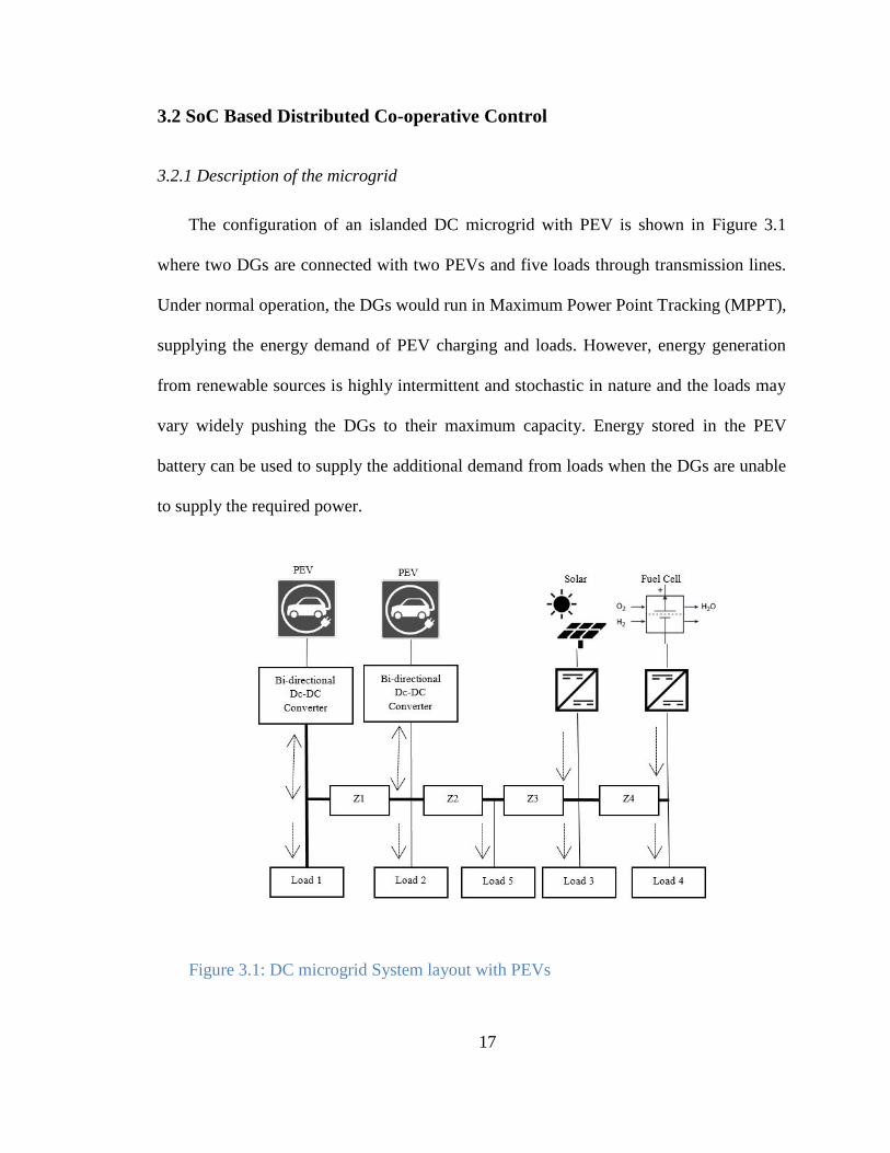
The configuration of an islanded DC microgrid with PEV is shown in Figure 3.1
where two DGs are connected with two PEVs and five loads through transmission lines.
Under normal operation, the DGs would run in Maximum Power Point Tracking (MPPT),
supplying the energy demand of PEV charging and loads. However, energy generation
from renewable sources is highly intermittent and stochastic in nature and the loads may
vary widely pushing the DGs to their maximum capacity. Energy stored in the PEV
battery can be used to supply the additional demand from loads when the DGs are unable
to supply the required power.
Figure 3.1: DC microgrid System layout with PEVs
18
Whichever is supplying the energy demand, i.e., DGs, PEVs, the load has to be
distributed according to the ratings of the energy suppliers to guarantee that none of them
are overloaded. Additional care has to be taken for PEV batteries during charging and
discharging process, as available energy from the batteries also depends on their SoC. To
prevent the overuse and prolong the life of PEV batteries, SoC of each of the PEV
batteries has to be balanced and a power equalization must be maintained during their
charging and discharging process [26]. In the discharging mode of the PEVs, batteries
with more SoC should supply more power than those with a lower SoC. A PEV
disconnects from the microgrid when the SoC of its battery reaches the minimum
acceptable limit and waits for a charging signal to commence charging. Meanwhile,
during the charging process, a battery with lower SoC should charge faster than that with
a higher SoC. When SoC reaches the maximum limit, the corresponding PEV waits for a
discharging signal after disconnecting from the microgrid.
3.2.2 Background on graph theory
A directed graph (diagraph) in a communication network can be represented as
( ), where {
} is a set of nonempty N nodes connected
through a set of edges or arcs and the associated adjacency matrix
[ ] . In the communication network of a microgrid, converters are considered as
nodes and the communication links are taken as edges. is the weight of the edges in
adjacency matrix , where if (
) and , otherwise. The
sequence of edges connecting the nodes
and
is called direct path. If a diagraph has
at least one root node from where all other nodes have direct path, then the diagraph is
19
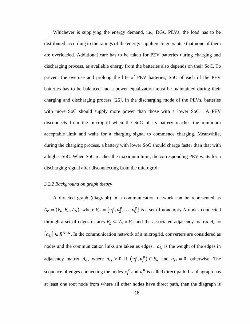
said to have a spinning tree [61]. The communication network for the microgrid in Figure
3.1 is planned with at least one spanning tree and is also chosen in such a way that in case
of any communication link failures the network would contain at least one spanning tree.
Figure 3.2 shows the communication network superimposed on the physical network of
the microgrid.
3.2.3 Distributed Co-operative Control (DCC)
Each converter i transmits a set of data, [ ], to its neighbors where is the
estimated average voltage across the microgrid measured at node i, and
is the
measured per-unit current at node i and
where is the rated current
of i-th converter of a DG and is the instantaneous current at node i .
Figure 3.2: Communication network layout over physical network [13]
20
In the secondary control of the DC microgrid, local and neighbor’s information are
used to adjust the local voltage set point using two correction factor ( and )
[13]:
(3.1)
where comes from voltage regulator, comes from current regulator, is the
virtual output-impedance, and
is the reference voltage of the DC microgrid.
The voltage regulator has two parts 1) voltage observer and 2) PI controller. The
voltage observer estimates the average voltage at node i using the average voltage
estimates, , of its neighboring nodes as shown below.
( ) ( ) ∫ ∑ ( ( ) ( ))
(3.2)
where ( ) is the measured voltage at node i, is the number of nodes exchanging
information with node i, and is the edge between node i and node j in the
communication graph. If all communication links are bi-directional, then converges to
the true average value [13]. The PI controller compares
and to produce the
. The current regulator uses one PI controller to compute from the current
mismatch, which compares
and the average of neighbor’s per-unit current,
:
∑ (
) (3.3)
21
where c is the coupling gain. This second correction, , factor ensures that the
converter’s per unit currents become equal so that they share the load in proportion of
their ratings.
3.2.4 SoC based Distributed Co-operative Control for PEV charging and discharging
The concept of SoC based droop control introduced in [26] uses only local
information for controlling the battery charging and discharging. In the present research
work, the availability of generation in the microgrid is also taken as an extra parameter in
the droop control by using the distributed cooperative control. The proposed method
controls the PEV battery discharging/charging for optimal use of the available generation
capacity that exists in the microgrid. The distributed cooperative control of DC microgrid
ensures a proportional load sharing among different converters by equalizing the per unit
currents of the converters, mathematically in steady state,
(3.4)
The per unit current of the i-th battery is updated as:
(
) (3.5)
where is the available current injection capacity of the i-th battery and
is
the maximum current injection capacity of that battery and n is the speed regulator for
SoC balancing. Combining (3.4) and (3.5) and considering the fact that the voltage drop
across the DC microgrid should be within 5% of the reference voltage regardless of the
cable length, the power sharing of PEV batteries during discharging mode can be
achieved according to the following equation:
22
(3.6)
(3.6) states that by updating the per unit current of i-th battery according to (3.5),
while in discharging mode, the proposed method not only balances the SoCs of the
batteries by faster discharging of the battery with higher SoC but also ensures the
distribution of load among the batteries according to their ratings so that none of them are
overloaded.
In charging mode, the conventional droop control method is modified to control the
speed of charging according to the available generation capacity of the DGs.
Conventional droop control method can be expressed as:
(3.7)
where , and are output reference voltage under loaded condition, droop
coefficient and the charging power respectively. For SoC balancing, the droop coefficient
was set to:
(3.8)
where is the constant droop coefficient for battery. With higher value of n,
charging rate of the battery will be higher [26]. As DCC guarantees that the per unit
currents of all the DGs would be same under steady state condition, that per unit current
is a good measure of the available power delivery capacity of the DGs. When the per unit
current approaches unity, there will be not much power left to meet the demand. So the
ideal condition would be to charge the PEVs faster when there is enough power in the
DGs and when the DGs are running closer to their maximum capacities, the charging rate
23
should be slower. This approach will ensure Demand Response (DR) within the
microgrid by controlling the charging current of the batteries depending on the
availability of power delivery capacity of all the DGs in the microgrid. To achieve DR,
the value of n was updated dynamically according to following equation:
( ) (3.9)
where k is the maximum allowable value of n and
is the per unit current of the
neighboring j-th DG. According to (3.9), the value of n decreases when
increases and
vice versa. A higher voltage, , from equation (3.7) will cause higher current from the
battery. As it is evident from (3.7) and (3.8) that the battery charging rate is higher with
higher value of n, the battery will charge faster when
is lower. But lower
means
that microgrid has more power to deliver than the case of higher
. From (3.4) and
(3.7)-(3.9), it can be shown that the charging power of PEV batteries should be controlled
using the following formulae to achieve DR:
(
)
(
)
(
) (3.10)
From (3.10), it is clear that the charging rate of the batteries with lower SoC are
higher than those with higher SoC.
Considering the simple equivalent circuit model given by [29] and [62] for a battery,
the SoC of the battery can be modelled as:
( ) ( )
( ) (3.11)
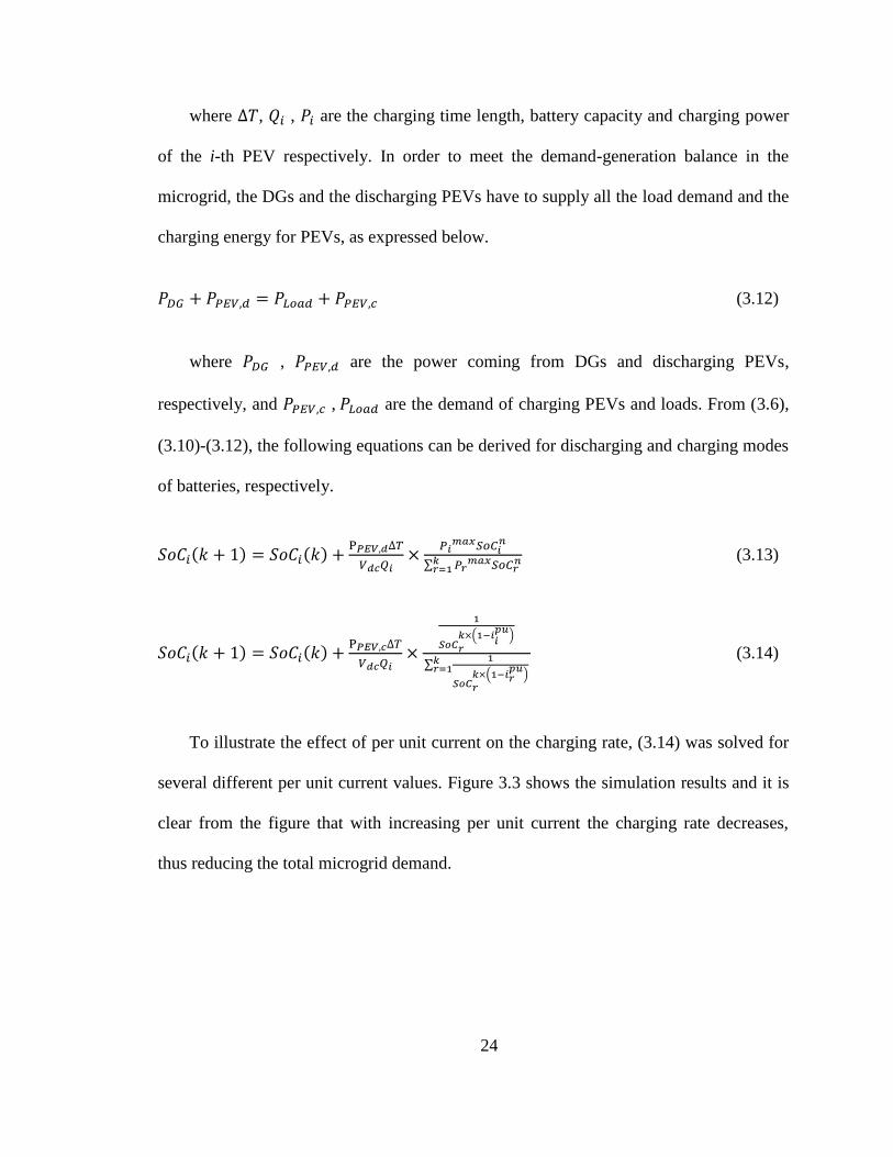
24
where , , are the charging time length, battery capacity and charging power
of the i-th PEV respectively. In order to meet the demand-generation balance in the
microgrid, the DGs and the discharging PEVs have to supply all the load demand and the
charging energy for PEVs, as expressed below.
(3.12)
where , are the power coming from DGs and discharging PEVs,
respectively, and , are the demand of charging PEVs and loads. From (3.6),
(3.10)-(3.12), the following equations can be derived for discharging and charging modes
of batteries, respectively.
( ) ( )
∑
(3.13)
( ) ( )
(
)
∑
(
)
(3.14)
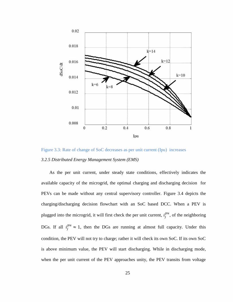
To illustrate the effect of per unit current on the charging rate, (3.14) was solved for
several different per unit current values. Figure 3.3 shows the simulation results and it is
clear from the figure that with increasing per unit current the charging rate decreases,
thus reducing the total microgrid demand.
25
Figure 3.3: Rate of change of SoC decreases as per unit current (Ipu) increases
3.2.5 Distributed Energy Management System (EMS)
As the per unit current, under steady state conditions, effectively indicates the
available capacity of the microgrid, the optimal charging and discharging decision for
PEVs can be made without any central supervisory controller. Figure 3.4 depicts the
charging/discharging decision flowchart with an SoC based DCC. When a PEV is
plugged into the microgrid, it will first check the per unit current,
, of the neighboring
DGs. If all , then the DGs are running at almost full capacity. Under this
condition, the PEV will not try to charge; rather it will check its own SoC. If its own SoC
is above minimum value, the PEV will start discharging. While in discharging mode,
when the per unit current of the PEV approaches unity, the PEV transits from voltage
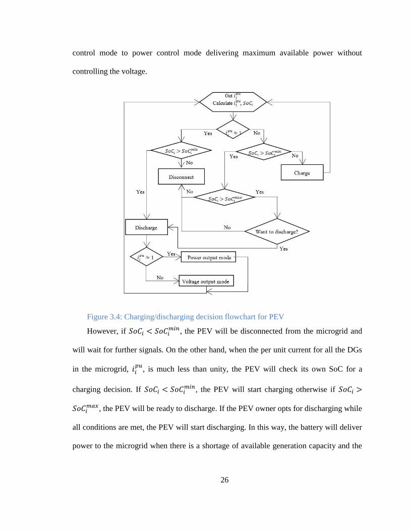
26
control mode to power control mode delivering maximum available power without
controlling the voltage.
Figure 3.4: Charging/discharging decision flowchart for PEV
However, if , the PEV will be disconnected from the microgrid and
will wait for further signals. On the other hand, when the per unit current for all the DGs
in the microgrid,
, is much less than unity, the PEV will check its own SoC for a
charging decision. If , the PEV will start charging otherwise if
, the PEV will be ready to discharge. If the PEV owner opts for discharging while
all conditions are met, the PEV will start discharging. In this way, the battery will deliver
power to the microgrid when there is a shortage of available generation capacity and the
27
battery will store energy when there is enough generation capacity. This scenario is ideal
for microgrids with renewable energy sources.
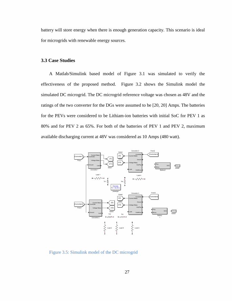
3.3 Case Studies
A Matlab/Simulink based model of Figure 3.1 was simulated to verify the
effectiveness of the proposed method. Figure 3.2 shows the Simulink model the
simulated DC microgrid. The DC microgrid reference voltage was chosen as 48V and the
ratings of the two converter for the DGs were assumed to be [20, 20] Amps. The batteries
for the PEVs were considered to be Lithiam-ion batteries with initial SoC for PEV 1 as
80% and for PEV 2 as 65%. For both of the batteries of PEV 1 and PEV 2, maximum
available discharging current at 48V was considered as 10 Amps (480 watt).
Figure 3.5: Simulink model of the DC microgrid
28
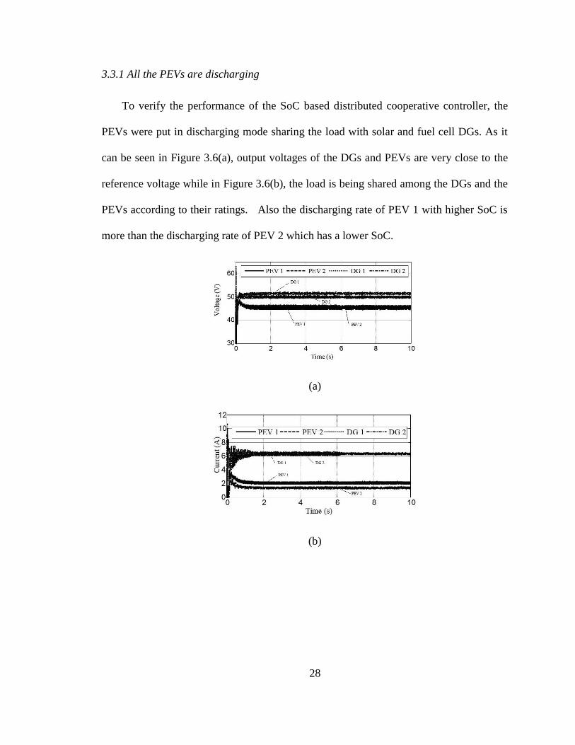
3.3.1 All the PEVs are discharging
To verify the performance of the SoC based distributed cooperative controller, the
PEVs were put in discharging mode sharing the load with solar and fuel cell DGs. As it
can be seen in Figure 3.6(a), output voltages of the DGs and PEVs are very close to the
reference voltage while in Figure 3.6(b), the load is being shared among the DGs and the
PEVs according to their ratings. Also the discharging rate of PEV 1 with higher SoC is
more than the discharging rate of PEV 2 which has a lower SoC.
(a)
(b)
29
(c)
Figure 3.6: Both of the PEVs are discharging. a) Voltage profile b) Load sharing
among the DGs and the PEVs c) SoC of the PEV batteries.
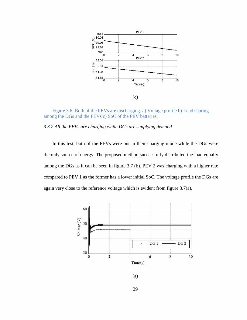
3.3.2 All the PEVs are charging while DGs are supplying demand
In this test, both of the PEVs were put in their charging mode while the DGs were
the only source of energy. The proposed method successfully distributed the load equally
among the DGs as it can be seen in figure 3.7 (b). PEV 2 was charging with a higher rate
compared to PEV 1 as the former has a lower initial SoC. The voltage profile the DGs are
again very close to the reference voltage which is evident from figure 3.7(a).
(a)

30
(b)
(c)
Figure 3.7: Both of the PEVs are charging a) Voltage profile b) Load sharing among
the DGs and the PEVs charging currents c) SoC of the PEV batteries.
31
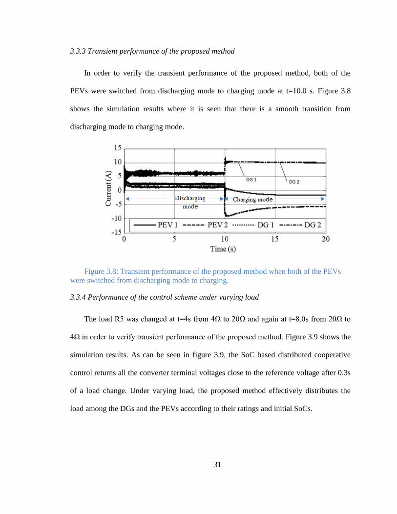
3.3.3 Transient performance of the proposed method
In order to verify the transient performance of the proposed method, both of the
PEVs were switched from discharging mode to charging mode at t=10.0 s. Figure 3.8
shows the simulation results where it is seen that there is a smooth transition from
discharging mode to charging mode.
Figure 3.8: Transient performance of the proposed method when both of the PEVs
were switched from discharging mode to charging.
3.3.4 Performance of the control scheme under varying load
The load R5 was changed at t=4s from 4Ω to 20Ω and again at t=8.0s from 20Ω to
4Ω in order to verify transient performance of the proposed method. Figure 3.9 shows the
simulation results. As can be seen in figure 3.9, the SoC based distributed cooperative
control returns all the converter terminal voltages close to the reference voltage after 0.3s
of a load change. Under varying load, the proposed method effectively distributes the
load among the DGs and the PEVs according to their ratings and initial SoCs.
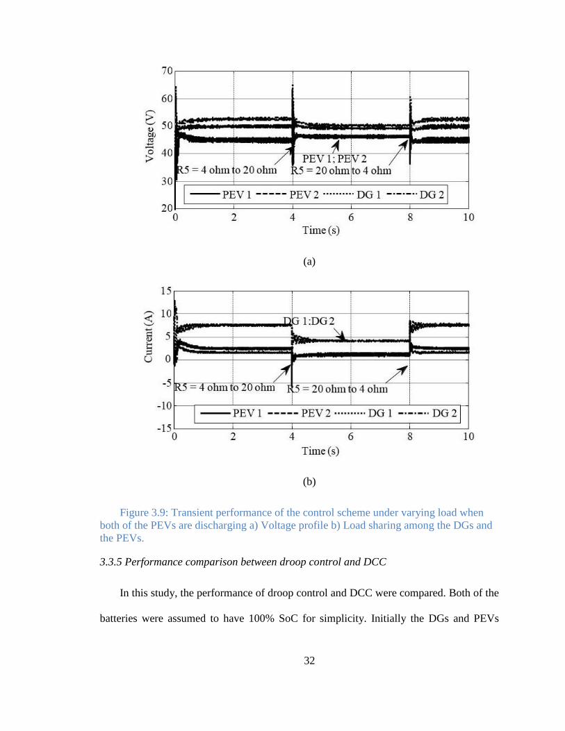
32
(a)
(b)
Figure 3.9: Transient performance of the control scheme under varying load when
both of the PEVs are discharging a) Voltage profile b) Load sharing among the DGs and
the PEVs.
3.3.5 Performance comparison between droop control and DCC
In this study, the performance of droop control and DCC were compared. Both of the
batteries were assumed to have 100% SoC for simplicity. Initially the DGs and PEVs
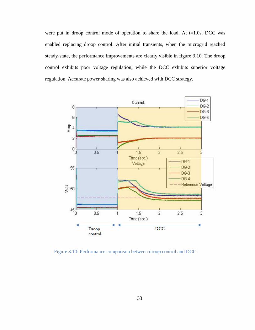
33
were put in droop control mode of operation to share the load. At t=1.0s, DCC was
enabled replacing droop control. After initial transients, when the microgrid reached
steady-state, the performance improvements are clearly visible in figure 3.10. The droop
control exhibits poor voltage regulation, while the DCC exhibits superior voltage
regulation. Accurate power sharing was also achieved with DCC strategy.
Figure 3.10: Performance comparison between droop control and DCC
34
3.4 Conclusion
In this chapter, a SoC based distributed cooperative control has been proposed for
PEV charging and discharging in an isolated DC microgrid. Available generation
capacity of the microgrid was estimated using DCC without requiring a central control
mechanism. This estimation was used to control the charging rate of PEVs to reduce the
burden on the power generation units, i.e., DGs and discharging PEVs. The proposed
method ensures a proportional load sharing among the DGs and discharging PEVs
according to their ratings. While in discharging mode, the SoC balancing is also
considered. Finally, a distributed EMS was proposed to coordinate the
charging/discharging decisions using information only from the neighboring DGs or
PEVs. Simulation results were presented to illustrate the effectiveness of the proposed
method.
35
Chapter 4
Control of AC microgrid in islanded mode of operation
4.1 Overview
In This chapter models for each distributed energy resource (DER) and the AC
microgrid where the DERs are connected are presented. A Simplified model of the three-
phase inverter in synchronous reference frame (d-q frame) and droop control for AC
microgrid and DCC for AC microgrid in islanded mode are presented.
4.2 Dynamic Model of Inverter based DGs
Each DG is connected to the microgrid through an impedance with
is the phase angle difference between voltages of DG bus, , and the Point of Common
Coupling, . Then the real and reactive powers shared by each DG with the microgrid
is given by,
( ( )) (4.1)
( ( )) (4.2)
(4.1) and (4.2) indicate that for a highly inductive line, real power is mostly
determined by voltage angle, and reactive power is determined by the amplitude of
voltage source converter (VSC) voltage. Thus real power can be shared by the DGs in a
36
microgrid by inserting an artificial droop in the DG frequency and reactive power can be
shared by inserting an artificial droop in DG voltage magnitude as in (4.3) and (4.4),
(4.3)
(4.4)
(4.5)
where
are d-axis inverter voltage, q-axis inverter voltage,
reference voltage for the inverter, reference angular frequency, angular frequency, real
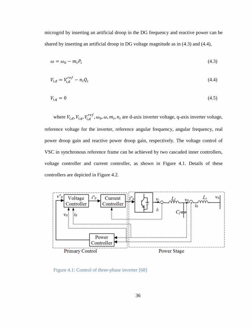
power droop gain and reactive power droop gain, respectively. The voltage control of
VSC in synchronous reference frame can be achieved by two cascaded inner controllers,
voltage controller and current controller, as shown in Figure 4.1. Details of these
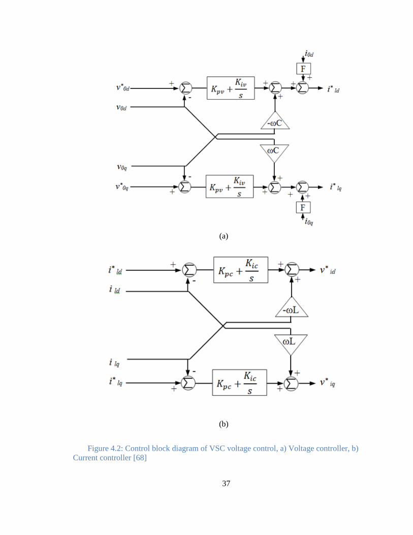
controllers are depicted in Figure 4.2.
Figure 4.1: Control of three-phase inverter [68]
37
(a)
(b)
Figure 4.2: Control block diagram of VSC voltage control, a) Voltage controller, b)
Current controller [68]
38
The droop gains are calculated based on the maximum allowable change of
frequency and voltage as in (4.6)-(4.7)
(4.6)
(4.7)
By increasing the droop gain coefficients and , real and reactive power sharing
accuracy among the DGs in a microgrid can be improved, but this will adversely affect
the frequency and voltage regulation [63]-[64]. High values of droop gains can also lead
to system instability and a poor transient response [65]. As the phase angle of voltage
source converter (VSC) can be changed instantaneously, phase angle can be drooped
instead of frequency drooping for real power sharing as follows:
(4.8)
The benefit of the above approach is the operation in constant frequency. However,
when the load angle is large, this approach suffers from lower stability margins
[65],[66],[67]. A centralized control approach may be adopted as in [64] to mitigate this
stability problem. But centralized control system is not only costlier but also susceptible
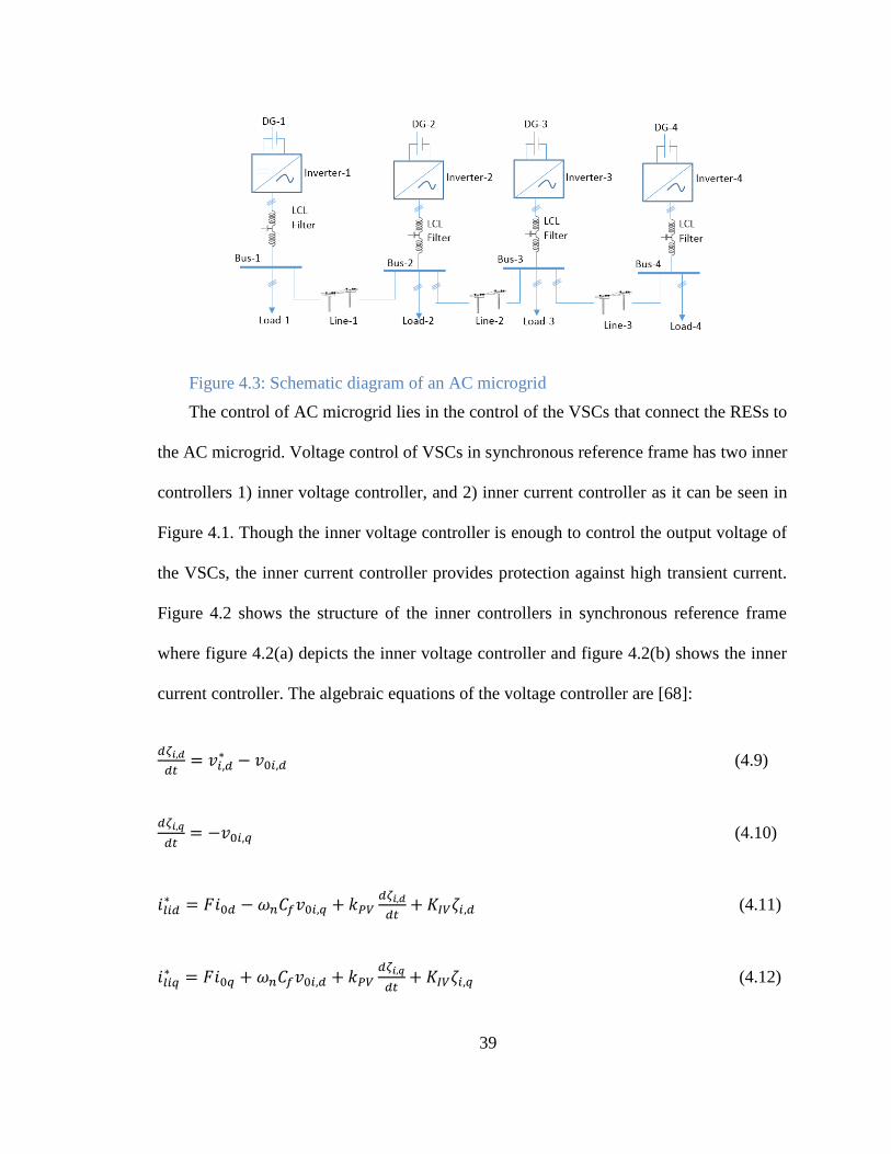
to collapse in case of any communication link failures. Figure 4.3 shows a schematic
diagram of four bus AC microgrid where each bus is connected to a DG through an
interfacing VSC, in this case inverters, and associated LCL filters.
39
Figure 4.3: Schematic diagram of an AC microgrid
The control of AC microgrid lies in the control of the VSCs that connect the RESs to
the AC microgrid. Voltage control of VSCs in synchronous reference frame has two inner
controllers 1) inner voltage controller, and 2) inner current controller as it can be seen in
Figure 4.1. Though the inner voltage controller is enough to control the output voltage of
the VSCs, the inner current controller provides protection against high transient current.
Figure 4.2 shows the structure of the inner controllers in synchronous reference frame
where figure 4.2(a) depicts the inner voltage controller and figure 4.2(b) shows the inner
current controller. The algebraic equations of the voltage controller are [68]:
(4.9)
(4.10)
(4.11)
(4.12)
40
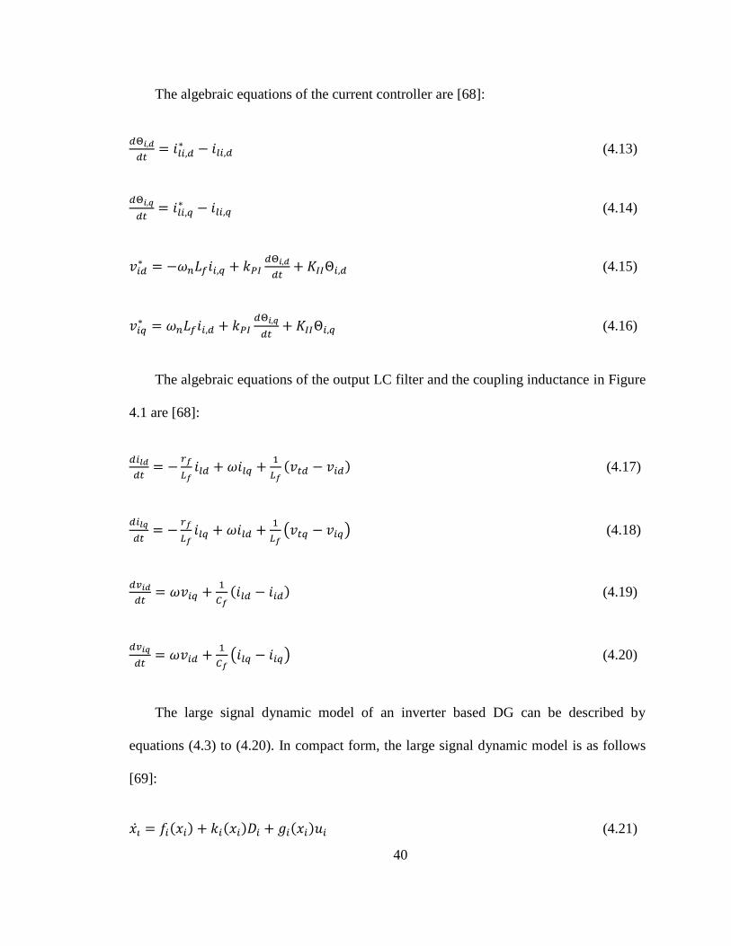
The algebraic equations of the current controller are [68]:
(4.13)
(4.14)
(4.15)
(4.16)
The algebraic equations of the output LC filter and the coupling inductance in Figure
4.1 are [68]:
( ) (4.17)
( ) (4.18)
( ) (4.19)
( ) (4.20)
The large signal dynamic model of an inverter based DG can be described by
equations (4.3) to (4.20). In compact form, the large signal dynamic model is as follows
[69]:
( ) ( ) ( ) (4.21)
41
( ) (4.22)
The state vector in (4.21) and (4.22) is defined as:
[ ] (4.23)
is considered as a known disturbance and is given by . The
other functions of ( ), ( ), ( ) can be synthesized from equations (4.3) to (4.20).
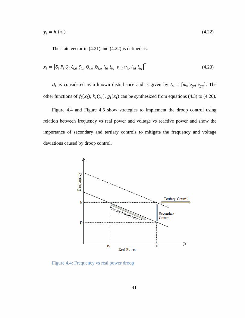
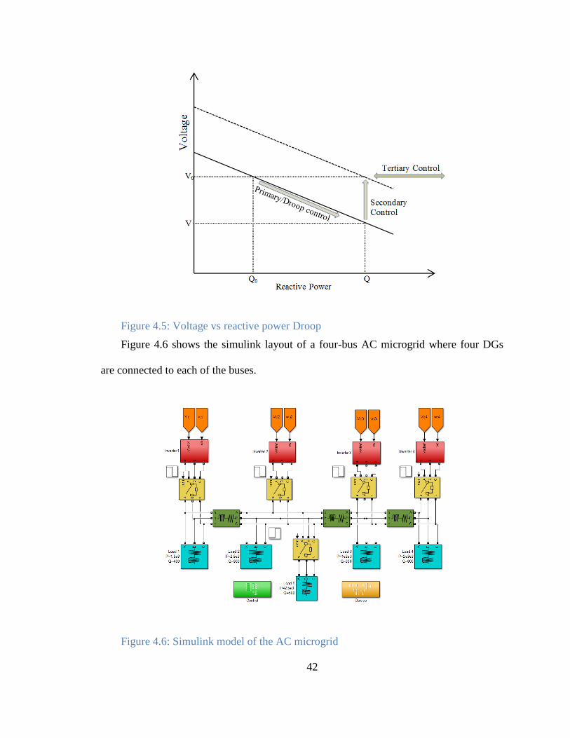
Figure 4.4 and Figure 4.5 show strategies to implement the droop control using
relation between frequency vs real power and voltage vs reactive power and show the
importance of secondary and tertiary controls to mitigate the frequency and voltage
deviations caused by droop control.
Figure 4.4: Frequency vs real power droop
42
Figure 4.5: Voltage vs reactive power Droop
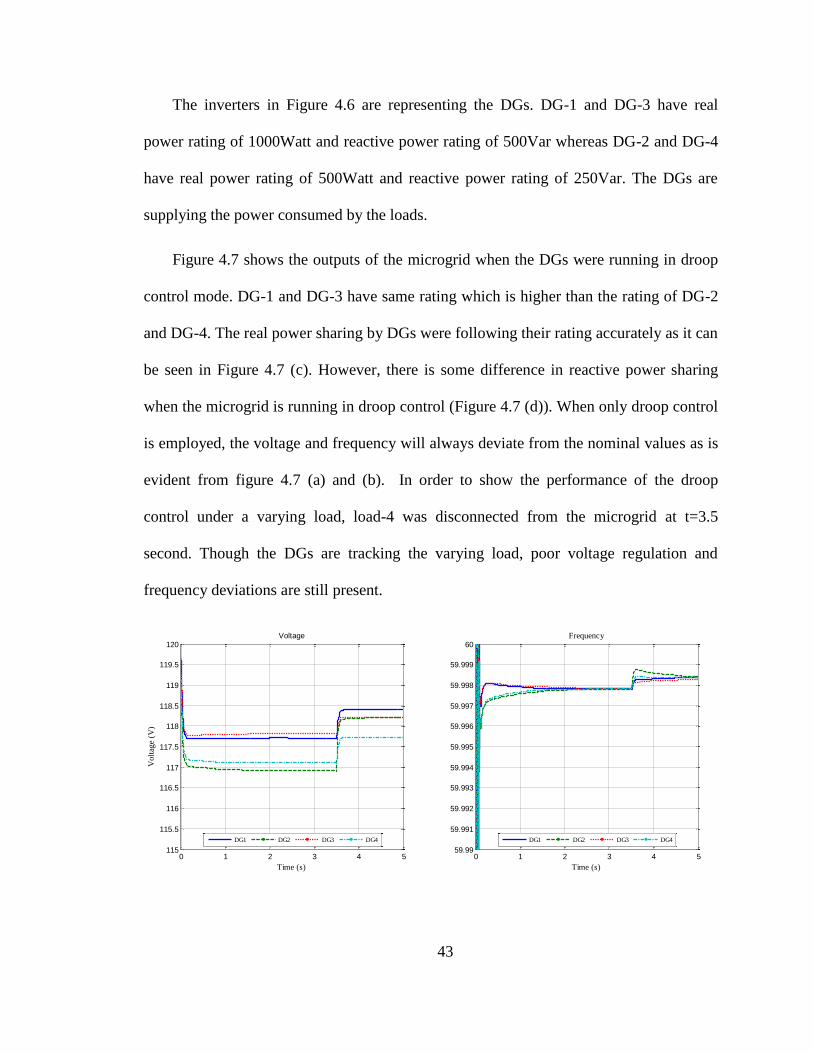
Figure 4.6 shows the simulink layout of a four-bus AC microgrid where four DGs
are connected to each of the buses.
Figure 4.6: Simulink model of the AC microgrid
43
The inverters in Figure 4.6 are representing the DGs. DG-1 and DG-3 have real
power rating of 1000Watt and reactive power rating of 500Var whereas DG-2 and DG-4
have real power rating of 500Watt and reactive power rating of 250Var. The DGs are
supplying the power consumed by the loads.
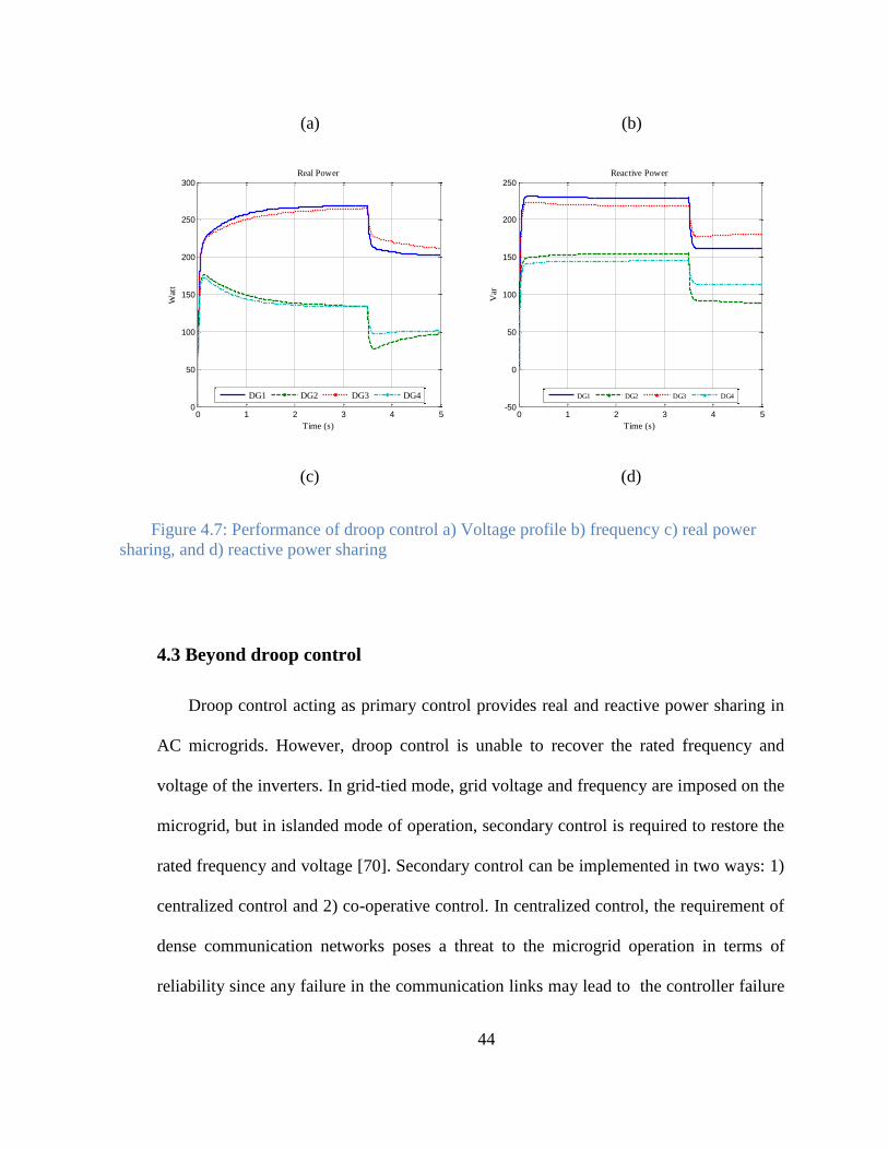
Figure 4.7 shows the outputs of the microgrid when the DGs were running in droop
control mode. DG-1 and DG-3 have same rating which is higher than the rating of DG-2
and DG-4. The real power sharing by DGs were following their rating accurately as it can
be seen in Figure 4.7 (c). However, there is some difference in reactive power sharing
when the microgrid is running in droop control (Figure 4.7 (d)). When only droop control
is employed, the voltage and frequency will always deviate from the nominal values as is
evident from figure 4.7 (a) and (b). In order to show the performance of the droop
control under a varying load, load-4 was disconnected from the microgrid at t=3.5
second. Though the DGs are tracking the varying load, poor voltage regulation and
frequency deviations are still present.
0 1 2 3 4 5115
115.5
116
116.5
117
117.5
118
118.5
119
119.5
120
Time (s)
Vo
ltag
e (V
)
Voltage
DG1 DG2 DG3 DG4
0 1 2 3 4 559.99
59.991
59.992
59.993
59.994
59.995
59.996
59.997
59.998
59.999
60Frequency
Time (s)
DG1 DG2 DG3 DG4
44
(a) (b)
(c)
(d)
4.3 Beyond droop control
Droop control acting as primary control provides real and reactive power sharing in
AC microgrids. However, droop control is unable to recover the rated frequency and
voltage of the inverters. In grid-tied mode, grid voltage and frequency are imposed on the
microgrid, but in islanded mode of operation, secondary control is required to restore the
rated frequency and voltage [70]. Secondary control can be implemented in two ways: 1)
centralized control and 2) co-operative control. In centralized control, the requirement of
dense communication networks poses a threat to the microgrid operation in terms of
reliability since any failure in the communication links may lead to the controller failure
0 1 2 3 4 50
50
100
150
200
250
300Real Power
Time (s)
Wat
t
DG1 DG2 DG3 DG4
0 1 2 3 4 5-50
0
50
100
150
200
250Reactive Power
Time (s)
Var
DG1 DG2 DG3 DG4
Figure 4.7: Performance of droop control a) Voltage profile b) frequency c) real power
sharing, and d) reactive power sharing
45
while and at the same time implementation of centralized controllers is costly.
Distributed co-operative controller gets an upper hand with respect to centralized
controller because of the requirement of lower number of communication links, resiliency
and robustness to communication link failures.
4.3.1 Distributed co-operative control (DCC) for AC microgrid:
In order to implement the DCC for an AC microgrid, a communication graph with
adjacency matrix [ ] is required. The communication graph should have
the following characteristics:
Must contain at least one spanning tree
The graph should have balanced Laplacian matrix
The graph should carry minimum redundancy
Each DG, considered as a node in a communication graph, shares a set of
information from its neighboring DGs. The information set shared by the DGs is
expressed as {
}, where is the overall estimated average voltage
magnitude for the whole microgrid calculated at node i,
is the normalized delivered
real power by and is calculated as
, and
is the normalized
delivered reactive power by and is calculated as
. Using this set of
information from neighboring DGs, the DCC tries to achieve 1) a nominal voltage at all
buses 2) nominal frequency for the microgrid 3) sharing of the real power and reactive
power of the DGs according to their ratings.
46
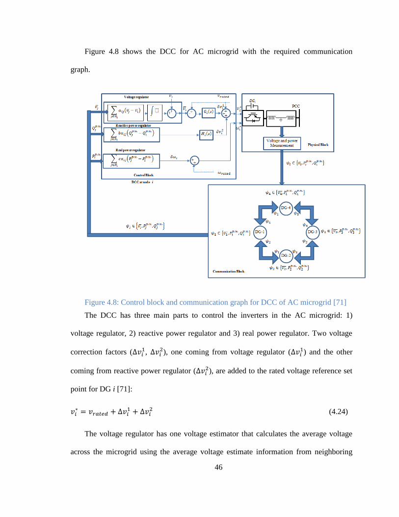
Figure 4.8 shows the DCC for AC microgrid with the required communication
graph.
Figure 4.8: Control block and communication graph for DCC of AC microgrid [71]
The DCC has three main parts to control the inverters in the AC microgrid: 1)
voltage regulator, 2) reactive power regulator and 3) real power regulator. Two voltage
correction factors ( ,
), one coming from voltage regulator ( ) and the other
coming from reactive power regulator ( ), are added to the rated voltage reference set
point for DG i [71]:
(4.24)
The voltage regulator has one voltage estimator that calculates the average voltage
across the microgrid using the average voltage estimate information from neighboring
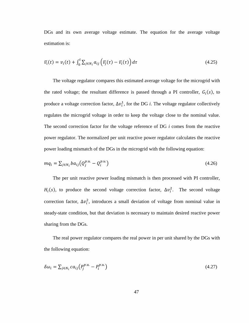
47
DGs and its own average voltage estimate. The equation for the average voltage
estimation is:
( ) ( ) ∫ ∑ ( ( ) ( ))
(4.25)
The voltage regulator compares this estimated average voltage for the microgrid with
the rated voltage; the resultant difference is passed through a PI controller, ( ), to
produce a voltage correction factor, , for the DG i. The voltage regulator collectively
regulates the microgrid voltage in order to keep the voltage close to the nominal value.
The second correction factor for the voltage reference of DG i comes from the reactive
power regulator. The normalized per unit reactive power regulator calculates the reactive
power loading mismatch of the DGs in the microgrid with the following equation:
∑ (
) (4.26)
The per unit reactive power loading mismatch is then processed with PI controller,
( ), to produce the second voltage correction factor, . The second voltage
correction factor, , introduces a small deviation of voltage from nominal value in
steady-state condition, but that deviation is necessary to maintain desired reactive power
sharing from the DGs.
The real power regulator compares the real power in per unit shared by the DGs with
the following equation:
∑ (
) (4.27)
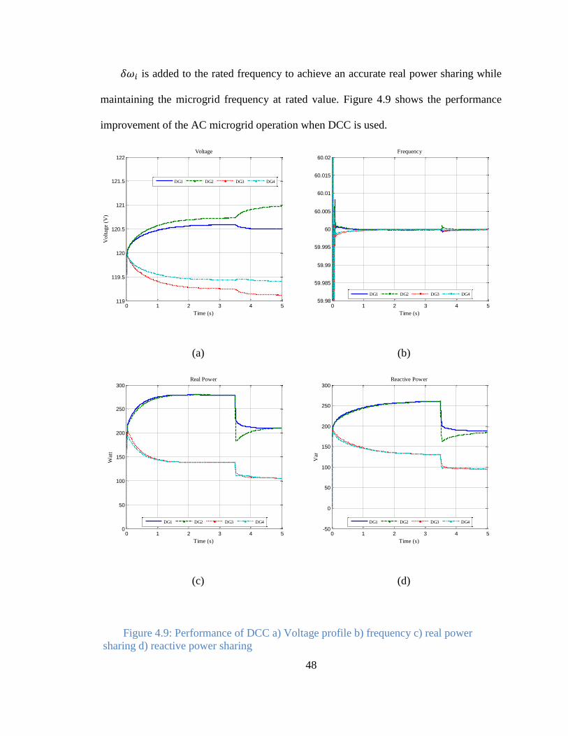
48
is added to the rated frequency to achieve an accurate real power sharing while
maintaining the microgrid frequency at rated value. Figure 4.9 shows the performance
improvement of the AC microgrid operation when DCC is used.
(a)
(b)
(c)
(d)
0 1 2 3 4 5119
119.5
120
120.5
121
121.5
122Voltage
Time (s)
Vo
ltag
e (V
)
DG1 DG2 DG3 DG4
0 1 2 3 4 559.98
59.985
59.99
59.995
60
60.005
60.01
60.015
60.02Frequency
Time (s)
DG1 DG2 DG3 DG4
0 1 2 3 4 50
50
100
150
200
250
300Real Power
Time (s)
Wat
t
DG1 DG2 DG3 DG4
0 1 2 3 4 5-50
0
50
100
150
200
250
300Reactive Power
Time (s)
Var
DG1 DG2 DG3 DG4
Figure 4.9: Performance of DCC a) Voltage profile b) frequency c) real power
sharing d) reactive power sharing
49
The AC microgrid simulated to verify the DCC is same as the microgrid that was
tested for droop control AC microgrid. In this case, DG1 and DG 2 are assumed to have
same real power and reactive power rating and DG3 and DG4 are also assumed to have
same ratings. However, the DG-1 & 2 have twice the power rating than that of DG-3 & 4.
Figure 4.9(c) and (d) clearly show that DGs are sharing real power and reactive power
exactly according to their rating. The voltage profile of the microgrid, as it can be seen in
Figure 4.9(a), shows superior performance than the of the droop control. Except during
transients, the microgrid frequency is also very close to its nominal value. In order to
verify the transient performance of the controller, the load-4 was disconnected from the
microgrid at t=3.5s. From the curves in Figure 4.9(a)-Figure 4.9(d), it is clear that the
controller is able to track the changes in the load accurately while maintaining the voltage
and frequency close to their nominal values.
50
Chapter 5
Co-operative control for AC/DC hybrid microgrid
5.1 Overview
Both the AC and DC microgrids have some advantages and disadvantages of their
own. Hybrid AC/DC microgrids have been proposed to take advantage of these two types
of microgrid in order to provide a better platform for integration of DGs in power system.
Hybrid AC/DC microgrids use interfacing converters (IC) to link the AC and DC
subgrids within the hybrid microgrid. The power management control of hybrid AC/DC
microgrids then focuses on the control of this IC. When the hybrid system is running in
an islanded mode of operation, the IC considers one subgrid as the source of energy while
the other subgrid is considered to be the load. In this chapter, a DCC for the hybrid
AC/DC microgrid realized through controlling the IC is proposed. A flexible hybrid
microgrid architecture has been considered where all the DGs and loads are conveniently
placed in either AC subgrid or DC subgrid depending on their AC or DC characteristics.
Overall system integration cost can be decreased and efficiency can be increased as this
flexible hybrid microgrid architecture reduces the number of various power conversion
stages such as AC-DC or DC-AC converters.
51
5.2 Hybrid microgrid architecture and mode of operations
Figure 5.1 shows a simple flexible structure of hybrid AC/DC microgrid which is
formed by one AC microgrid and one DC microgrid connected together through an
interfacing converter (IC). The subgrids in the hybrid system are serving their local loads.
The IC provides bi-directional power flow between the two subgrids depending on the
demand-supply constraints in the individual subgrids. Moreover, the hybrid microgrid
can be connected with the utility from the AC subgrid side by a static transfer switch
(STS). Under grid connected mode of operation, STS will remain closed and utility will
determine the overall dynamics of the hybrid system as the utility can be considered as an
infinite bus. The voltage and frequency of AC subgrid under grid connected mode will be
controlled by utility and the role of IC will be mainly to control the voltage of the DC
subgrid along with power sharing from the DC bus. The RESs connected in both of the
subgrids will mainly operate in maximum power point tracking (MPPT) mode to harness
the maximum power from the sources. In the islanded mode of operation, the DGs in
both of the subgrids will participate in power balancing as well as system stability. The
following section describes the performance requirements for both of these modes of
operation.
5.2.1 Grid-connected mode of operation for hybrid microgrid:
During grid connected mode, the voltage and frequency of the AC subgrid is
controlled by the utility. The voltage of the DC subgrid is controlled by the utility
through the IC. However, DGs connected to the AC subgrid will be responsible for
generating fixed real/reactive power or vary their real/reactive power by a small amount
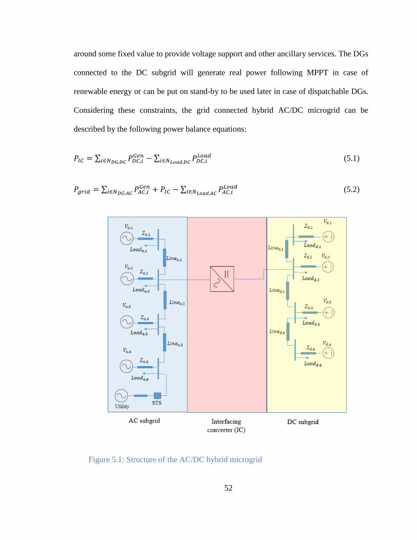
52
around some fixed value to provide voltage support and other ancillary services. The DGs
connected to the DC subgrid will generate real power following MPPT in case of
renewable energy or can be put on stand-by to be used later in case of dispatchable DGs.
Considering these constraints, the grid connected hybrid AC/DC microgrid can be
described by the following power balance equations:
∑
∑
(5.1)
∑
∑
(5.2)
Figure 5.1: Structure of the AC/DC hybrid microgrid
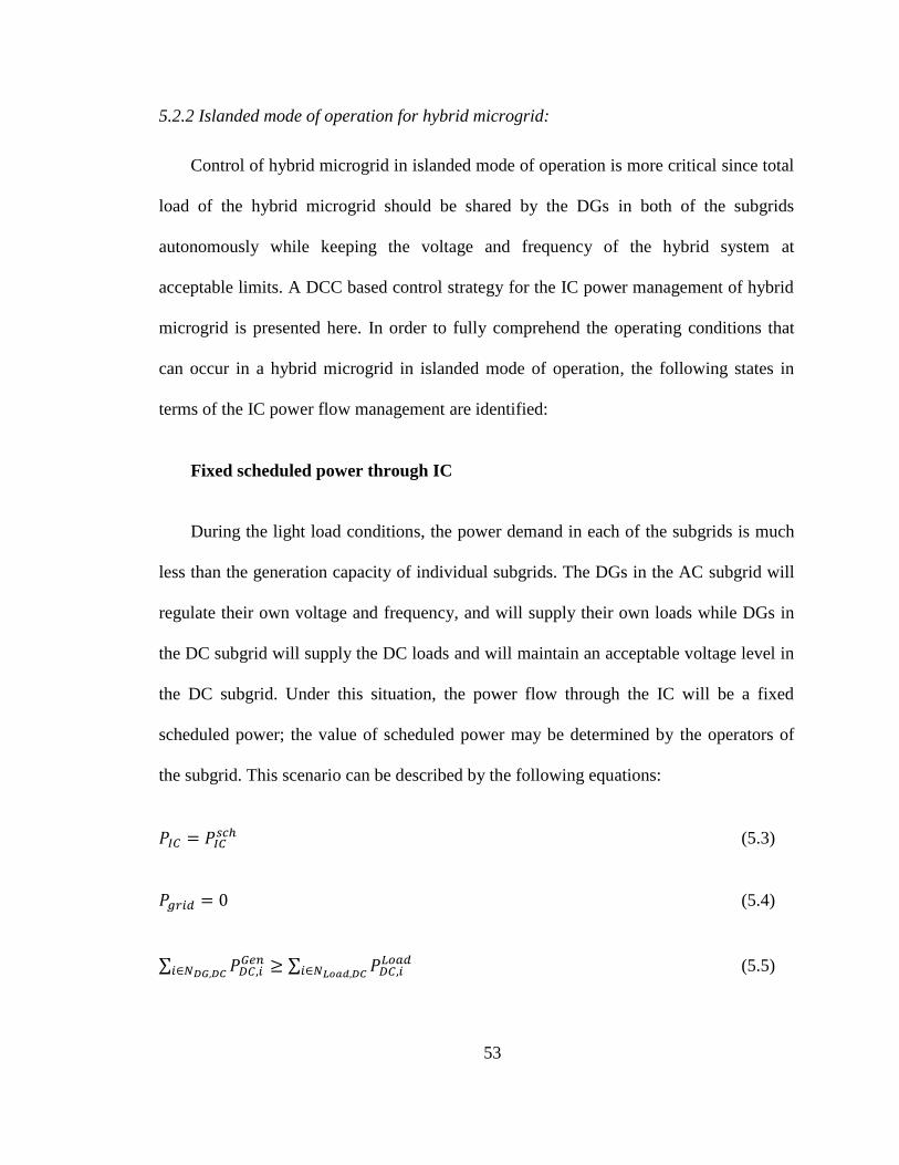
53
5.2.2 Islanded mode of operation for hybrid microgrid:
Control of hybrid microgrid in islanded mode of operation is more critical since total
load of the hybrid microgrid should be shared by the DGs in both of the subgrids
autonomously while keeping the voltage and frequency of the hybrid system at
acceptable limits. A DCC based control strategy for the IC power management of hybrid
microgrid is presented here. In order to fully comprehend the operating conditions that
can occur in a hybrid microgrid in islanded mode of operation, the following states in
terms of the IC power flow management are identified:
Fixed scheduled power through IC
During the light load conditions, the power demand in each of the subgrids is much
less than the generation capacity of individual subgrids. The DGs in the AC subgrid will
regulate their own voltage and frequency, and will supply their own loads while DGs in
the DC subgrid will supply the DC loads and will maintain an acceptable voltage level in
the DC subgrid. Under this situation, the power flow through the IC will be a fixed
scheduled power; the value of scheduled power may be determined by the operators of
the subgrid. This scenario can be described by the following equations:
(5.3)
(5.4)
∑
∑
(5.5)
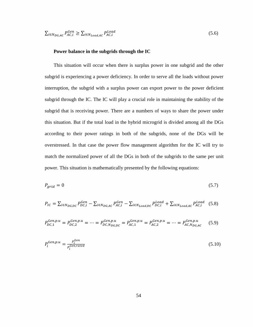
54
∑
∑
(5.6)
Power balance in the subgrids through the IC
This situation will occur when there is surplus power in one subgrid and the other
subgrid is experiencing a power deficiency. In order to serve all the loads without power
interruption, the subgrid with a surplus power can export power to the power deficient
subgrid through the IC. The IC will play a crucial role in maintaining the stability of the
subgrid that is receiving power. There are a numbers of ways to share the power under
this situation. But if the total load in the hybrid microgrid is divided among all the DGs
according to their power ratings in both of the subgrids, none of the DGs will be
overstressed. In that case the power flow management algorithm for the IC will try to
match the normalized power of all the DGs in both of the subgrids to the same per unit
power. This situation is mathematically presented by the following equations:
(5.7)
∑
∑
∑
∑
(5.8)
(5.9)
(5.10)
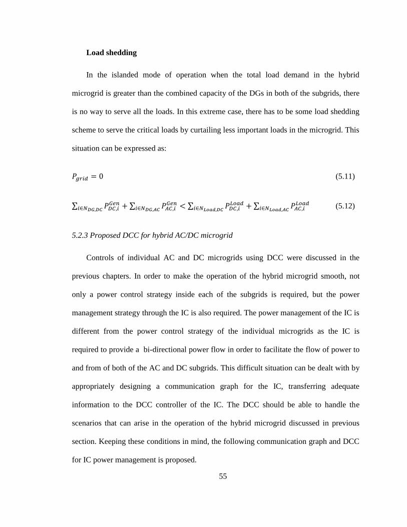
55
Load shedding
In the islanded mode of operation when the total load demand in the hybrid
microgrid is greater than the combined capacity of the DGs in both of the subgrids, there
is no way to serve all the loads. In this extreme case, there has to be some load shedding
scheme to serve the critical loads by curtailing less important loads in the microgrid. This
situation can be expressed as:
(5.11)
∑
∑
∑
∑
(5.12)
5.2.3 Proposed DCC for hybrid AC/DC microgrid
Controls of individual AC and DC microgrids using DCC were discussed in the
previous chapters. In order to make the operation of the hybrid microgrid smooth, not
only a power control strategy inside each of the subgrids is required, but the power
management strategy through the IC is also required. The power management of the IC is
different from the power control strategy of the individual microgrids as the IC is
required to provide a bi-directional power flow in order to facilitate the flow of power to
and from of both of the AC and DC subgrids. This difficult situation can be dealt with by
appropriately designing a communication graph for the IC, transferring adequate
information to the DCC controller of the IC. The DCC should be able to handle the
scenarios that can arise in the operation of the hybrid microgrid discussed in previous
section. Keeping these conditions in mind, the following communication graph and DCC
for IC power management is proposed.
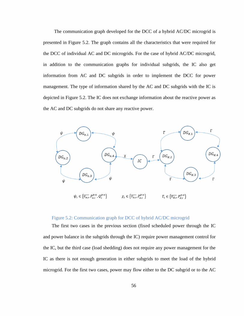
56
The communication graph developed for the DCC of a hybrid AC/DC microgrid is
presented in Figure 5.2. The graph contains all the characteristics that were required for
the DCC of individual AC and DC microgrids. For the case of hybrid AC/DC microgrid,
in addition to the communication graphs for individual subgrids, the IC also get
information from AC and DC subgrids in order to implement the DCC for power
management. The type of information shared by the AC and DC subgrids with the IC is
depicted in Figure 5.2. The IC does not exchange information about the reactive power as
the AC and DC subgrids do not share any reactive power.
Figure 5.2: Communication graph for DCC of hybrid AC/DC microgrid
The first two cases in the previous section (fixed scheduled power through the IC
and power balance in the subgrids through the IC) require power management control for
the IC, but the third case (load shedding) does not require any power management for the
IC as there is not enough generation in either subgrids to meet the load of the hybrid
microgrid. For the first two cases, power may flow either to the DC subgrid or to the AC
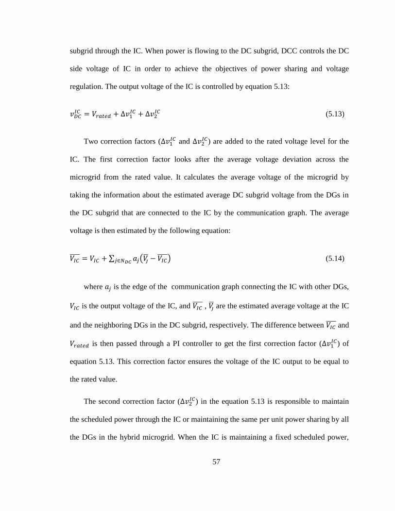
57
subgrid through the IC. When power is flowing to the DC subgrid, DCC controls the DC
side voltage of IC in order to achieve the objectives of power sharing and voltage
regulation. The output voltage of the IC is controlled by equation 5.13:
(5.13)
Two correction factors ( and
) are added to the rated voltage level for the
IC. The first correction factor looks after the average voltage deviation across the
microgrid from the rated value. It calculates the average voltage of the microgrid by
taking the information about the estimated average DC subgrid voltage from the DGs in
the DC subgrid that are connected to the IC by the communication graph. The average
voltage is then estimated by the following equation:
∑ (
) (5.14)
where is the edge of the communication graph connecting the IC with other DGs,
is the output voltage of the IC, and , are the estimated average voltage at the IC
and the neighboring DGs in the DC subgrid, respectively. The difference between and
is then passed through a PI controller to get the first correction factor ( ) of
equation 5.13. This correction factor ensures the voltage of the IC output to be equal to
the rated value.
The second correction factor ( ) in the equation 5.13 is responsible to maintain
the scheduled power through the IC or maintaining the same per unit power sharing by all
the DGs in the hybrid microgrid. When the IC is maintaining a fixed scheduled power,
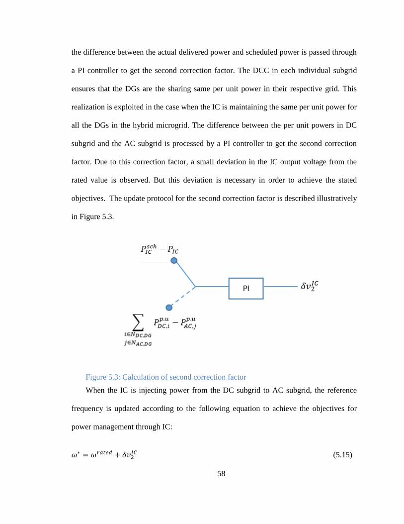
58
the difference between the actual delivered power and scheduled power is passed through
a PI controller to get the second correction factor. The DCC in each individual subgrid
ensures that the DGs are the sharing same per unit power in their respective grid. This
realization is exploited in the case when the IC is maintaining the same per unit power for
all the DGs in the hybrid microgrid. The difference between the per unit powers in DC
subgrid and the AC subgrid is processed by a PI controller to get the second correction
factor. Due to this correction factor, a small deviation in the IC output voltage from the
rated value is observed. But this deviation is necessary in order to achieve the stated
objectives. The update protocol for the second correction factor is described illustratively
in Figure 5.3.
Figure 5.3: Calculation of second correction factor
When the IC is injecting power from the DC subgrid to AC subgrid, the reference
frequency is updated according to the following equation to achieve the objectives for
power management through IC:
(5.15)
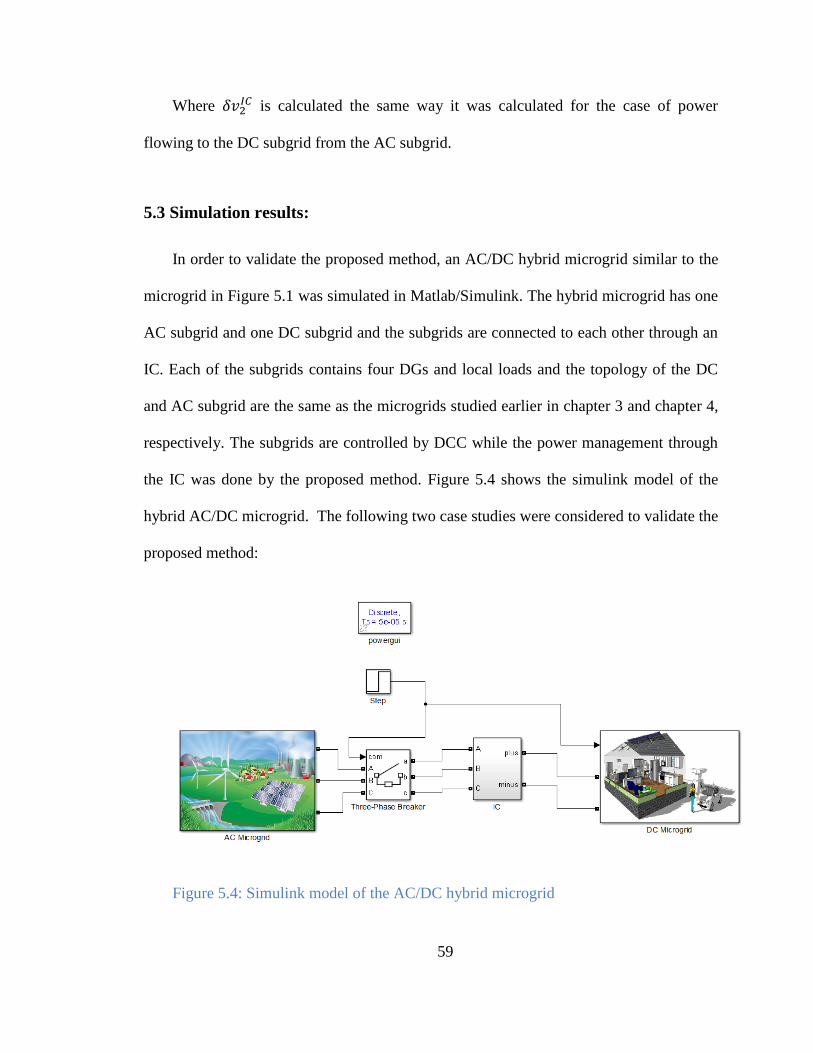
59
Where is calculated the same way it was calculated for the case of power
flowing to the DC subgrid from the AC subgrid.
5.3 Simulation results:
In order to validate the proposed method, an AC/DC hybrid microgrid similar to the
microgrid in Figure 5.1 was simulated in Matlab/Simulink. The hybrid microgrid has one
AC subgrid and one DC subgrid and the subgrids are connected to each other through an
IC. Each of the subgrids contains four DGs and local loads and the topology of the DC
and AC subgrid are the same as the microgrids studied earlier in chapter 3 and chapter 4,
respectively. The subgrids are controlled by DCC while the power management through
the IC was done by the proposed method. Figure 5.4 shows the simulink model of the
hybrid AC/DC microgrid. The following two case studies were considered to validate the
proposed method:
Figure 5.4: Simulink model of the AC/DC hybrid microgrid

60
5.3.1 Case 1:
In this case, the hybrid AC/DC microgrid is assumed to be operating with the
condition that a fixed scheduled power should flow through the IC. Figure 5.5 shows the
performance of the proposed method. Initially the AC subgrid and DC subgrid were
running separately and isolated from each other when the three-phase breaker was open.
At t=1.5s, the breaker was closed, and a fixed 80 W power was scheduled to flow through
the IC from the AC subgrid to the DC subgrid. It can be seen from Figure 5.5 (a) that the
power through the IC changes to fixed 80 watt at t=1.5s without any severe transient. The
power delivered by the DGs in the DC subgrid changes (Figure 5.5 (b)) as the DC
subgrid is receiving extra power from the AC subgrid. The voltage profile of the DC
subgrid remains at an acceptable limit which is evident from the Figure 5.5(b). The power
delivered by the DGs at AC subgrid also changes in order to generate this extra 80 W
power. At t=4s, an extra 200 W load was added in the DC subgrid to evaluate the
dynamic performance of the controller. From the curves in Figure 5.5, it is clear that
though there is an increase in the DC load, the power flow through the IC does not
change.
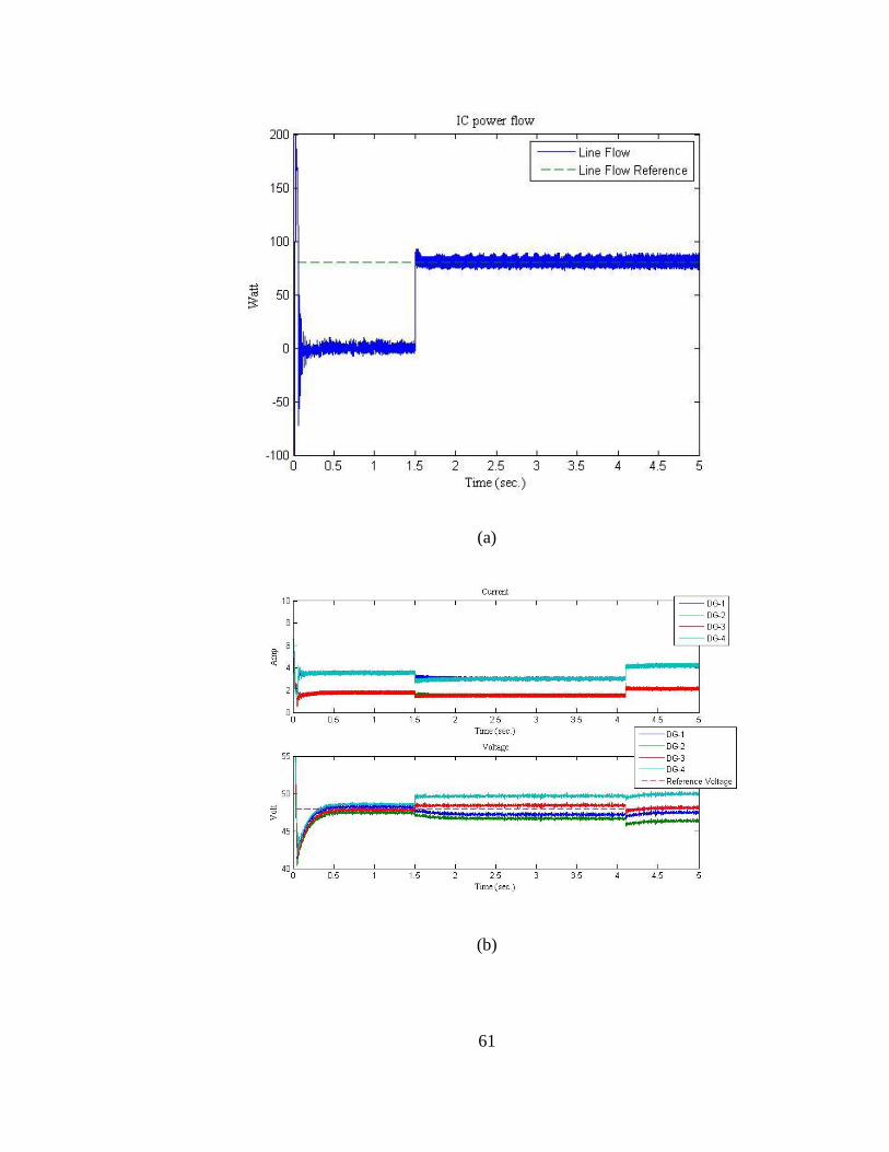
61
(a)
(b)
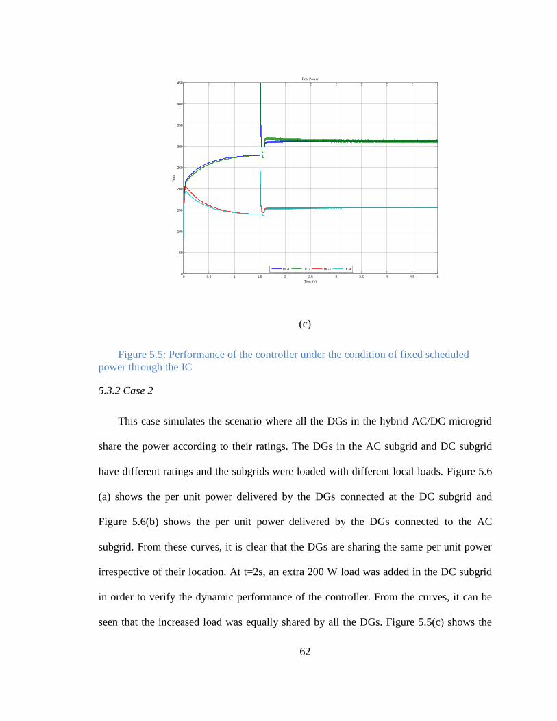
62
(c)
Figure 5.5: Performance of the controller under the condition of fixed scheduled
power through the IC
5.3.2 Case 2
This case simulates the scenario where all the DGs in the hybrid AC/DC microgrid
share the power according to their ratings. The DGs in the AC subgrid and DC subgrid
have different ratings and the subgrids were loaded with different local loads. Figure 5.6
(a) shows the per unit power delivered by the DGs connected at the DC subgrid and
Figure 5.6(b) shows the per unit power delivered by the DGs connected to the AC
subgrid. From these curves, it is clear that the DGs are sharing the same per unit power
irrespective of their location. At t=2s, an extra 200 W load was added in the DC subgrid
in order to verify the dynamic performance of the controller. From the curves, it can be
seen that the increased load was equally shared by all the DGs. Figure 5.5(c) shows the
0 0.5 1 1.5 2 2.5 3 3.5 4 4.5 50
50
100
150
200
250
300
350
400
450Real Power
Time (s)
Wat
t
DG1 DG2 DG3 DG4
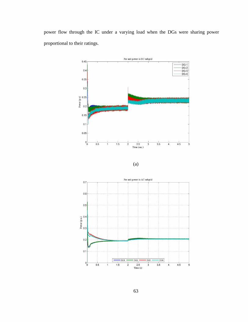
63
power flow through the IC under a varying load when the DGs were sharing power
proportional to their ratings.
(a)
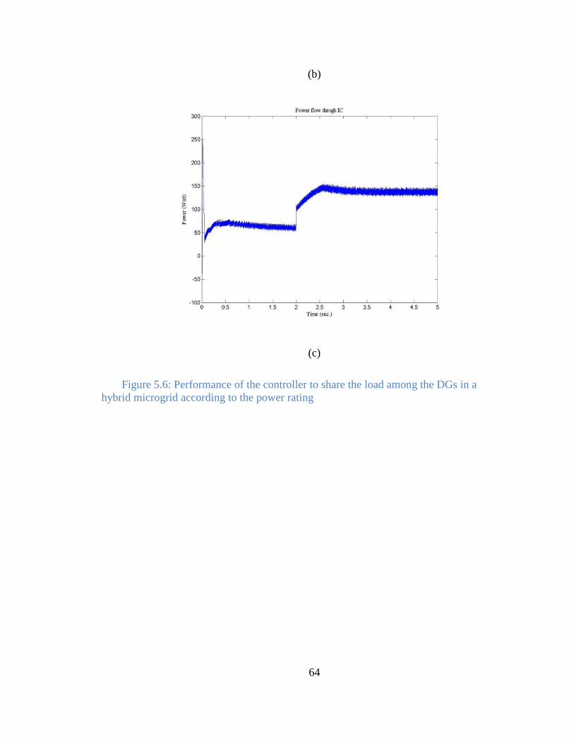
64
(b)
(c)
Figure 5.6: Performance of the controller to share the load among the DGs in a
hybrid microgrid according to the power rating
65
Chapter 6
Microgrid Laboratory Prototype
6.1 Overview
The types of hardware and their configurations in most of the Microgrid testbeds are
often fixed and require a good amount of work and time to change or upgrade the
hardware setup. These fixed-hardware microgrid testbeds are suitable for a limited
number of experiments; and cannot provide the platform to carry on a wide variety of
studies. The interactions between distributed generators (DGs) in a microgrid and the grid
can be very complex. The microgrid testbeds to study grid-connected mode of operation
are mostly connected with the utility. This approach also limits the number of plausible
grid condition scenarios that can happen under different conditions. In order to address
the aforementioned issues about laboratory scale microgrid testbeds, as a part of the
present research work, a highly flexible, scalable multifunctional microgrid testbed is
developed at the Power Electronic Research Laboratory (PERL), University of North
Dakota (UND). The PERL Microgrid (P-MG) offers a platform for Microgrid research
with the following characteristics:
A flexible, scalable design for the power network components and
communication network.
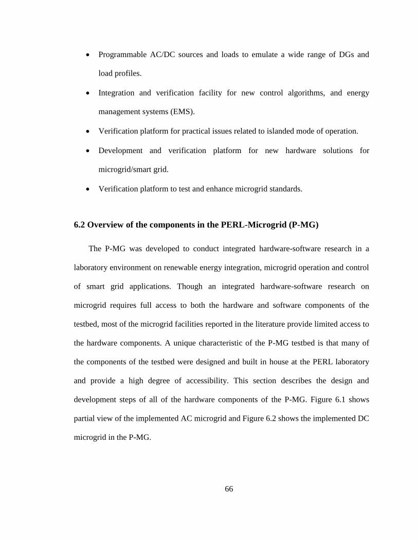
66
Programmable AC/DC sources and loads to emulate a wide range of DGs and
load profiles.
Integration and verification facility for new control algorithms, and energy
management systems (EMS).
Verification platform for practical issues related to islanded mode of operation.
Development and verification platform for new hardware solutions for
microgrid/smart grid.
Verification platform to test and enhance microgrid standards.
6.2 Overview of the components in the PERL-Microgrid (P-MG)
The P-MG was developed to conduct integrated hardware-software research in a
laboratory environment on renewable energy integration, microgrid operation and control
of smart grid applications. Though an integrated hardware-software research on
microgrid requires full access to both the hardware and software components of the
testbed, most of the microgrid facilities reported in the literature provide limited access to
the hardware components. A unique characteristic of the P-MG testbed is that many of
the components of the testbed were designed and built in house at the PERL laboratory
and provide a high degree of accessibility. This section describes the design and
development steps of all of the hardware components of the P-MG. Figure 6.1 shows
partial view of the implemented AC microgrid and Figure 6.2 shows the implemented DC
microgrid in the P-MG.
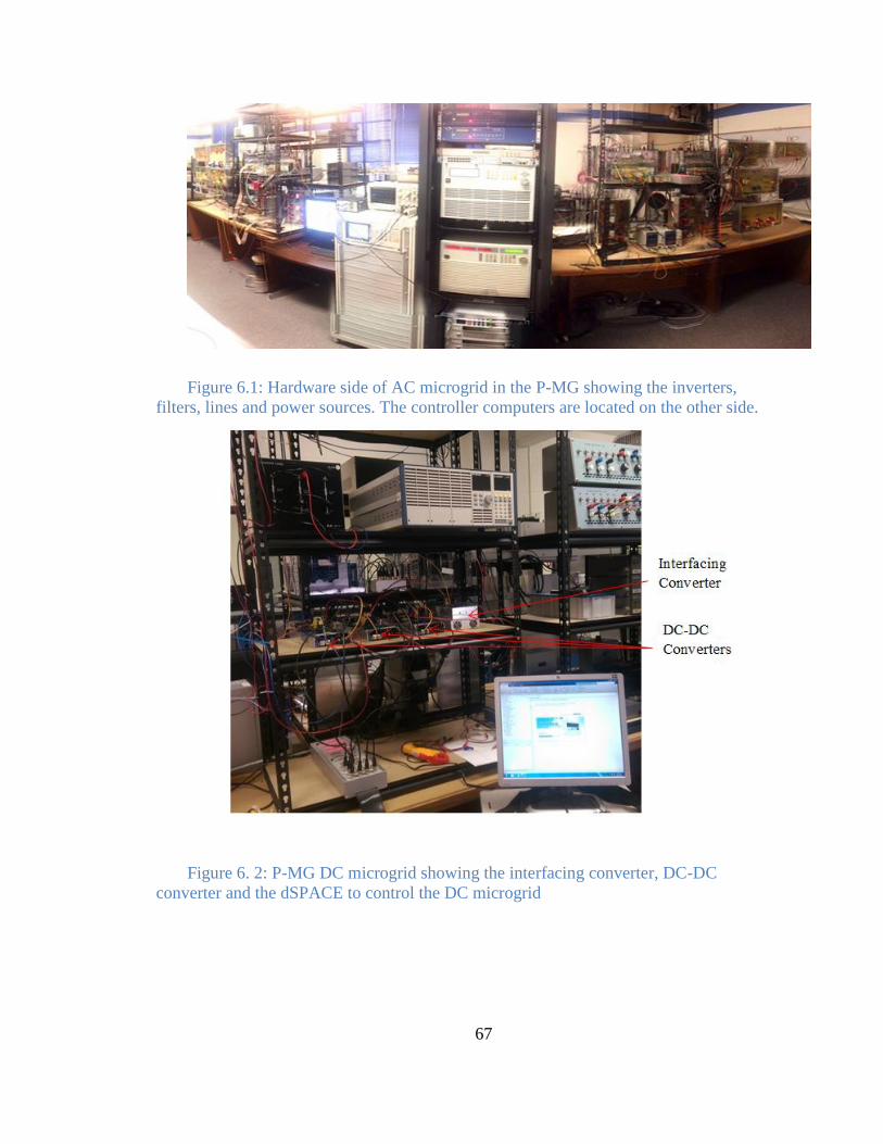
67
Figure 6.1: Hardware side of AC microgrid in the P-MG showing the inverters,
filters, lines and power sources. The controller computers are located on the other side.
Figure 6. 2: P-MG DC microgrid showing the interfacing converter, DC-DC
converter and the dSPACE to control the DC microgrid
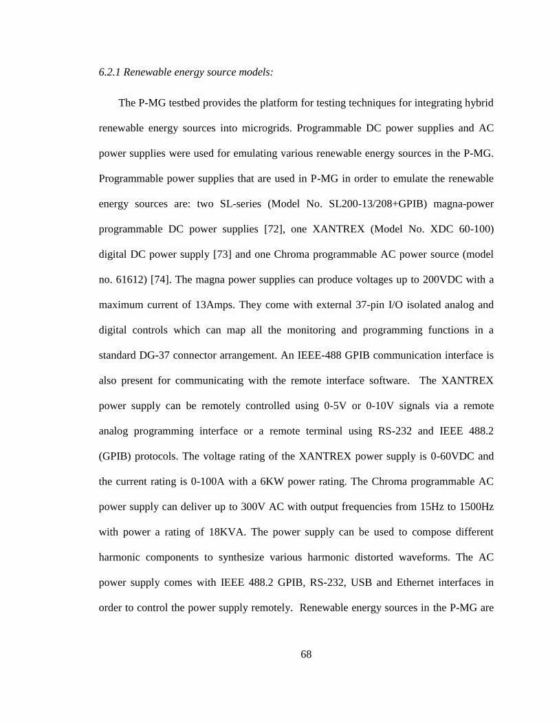
68
6.2.1 Renewable energy source models:
The P-MG testbed provides the platform for testing techniques for integrating hybrid
renewable energy sources into microgrids. Programmable DC power supplies and AC
power supplies were used for emulating various renewable energy sources in the P-MG.
Programmable power supplies that are used in P-MG in order to emulate the renewable
energy sources are: two SL-series (Model No. SL200-13/208+GPIB) magna-power
programmable DC power supplies [72], one XANTREX (Model No. XDC 60-100)
digital DC power supply [73] and one Chroma programmable AC power source (model
no. 61612) [74]. The magna power supplies can produce voltages up to 200VDC with a
maximum current of 13Amps. They come with external 37-pin I/O isolated analog and
digital controls which can map all the monitoring and programming functions in a
standard DG-37 connector arrangement. An IEEE-488 GPIB communication interface is
also present for communicating with the remote interface software. The XANTREX
power supply can be remotely controlled using 0-5V or 0-10V signals via a remote
analog programming interface or a remote terminal using RS-232 and IEEE 488.2
(GPIB) protocols. The voltage rating of the XANTREX power supply is 0-60VDC and
the current rating is 0-100A with a 6KW power rating. The Chroma programmable AC
power supply can deliver up to 300V AC with output frequencies from 15Hz to 1500Hz
with power a rating of 18KVA. The power supply can be used to compose different
harmonic components to synthesize various harmonic distorted waveforms. The AC
power supply comes with IEEE 488.2 GPIB, RS-232, USB and Ethernet interfaces in
order to control the power supply remotely. Renewable energy sources in the P-MG are

69
solar photovoltaic, wind, and fuel-cell technologies. Details of these emulators are
described below:
6.2.2 Photovoltaics (PV) simulator
There are numerous photovoltaics power systems in the market each having its own
dynamics and steady-state characteristics. Testing actual solar power systems is costly
and highly dependent on weather conditions [75]. That is why a simulator which can
confidently emulate the behavior of different photovoltaics power systems is a more
attractive choice for a microgrid testbed facility such as P-MG.
The Magna-power and XANTREX DC power supplies are used for emulating the
current and voltage characteristics of PV panels. A lookup table in a data memory
[76][77] or equations describing the semiconductor physics can be used to simulate the
behavior of PV panels [78]. The following chareacteristic equation is used at P-MG
for PV emulation representing a practical PV array [79]:
[
]
(6.1)
where and are the panel and saturation currents of the PV array, respectively.
The thermal voltage of the array when cells are connected in series is defined by
, is the electron charge, is Boltzmann constant, is temperature in Kelvin,
is the equivalent series resistance of the array, and is the equivalent parallel
resistance. The DC power supplies can reliably produce the static and dynamic behavior
70
of arrays of solar cells with different configurations under varying weather and load
conditions.
6.2.3 Energy storage systems (ESS) simulator
Since ESSs are relatively expensive, using real ESSs for testing different
charging/discharging algorithms and circuits is uneconomical [80]. Equations 2 to 4
were used to emulate the characteristic of an ESS such as batteries [81] with the
programmable DC power supplies:
( )
∫ ( ) ( ) (6.2)
( ) ( ) ( ) ( ) ( ) (6.3)
( ) ( ) ( ) ( ) (6.4)
where ( ) and are the present and initial state of charge (SoC) of the
battery, ( ) is the SoC dependent open circuit voltage, is the terminal
voltage of the ESS, is the battery current, and are maximum and
unavailable capacity of the ESS. The battery model updates the output voltage by taking
measurements of load current to reflect the charging/discharging mode of the emulated
battery. The ESS emulator can successfully mimic the behavior of ESS at different age,
temperature and state-of-charge (SoC) conditions reducing the development cost and
preventing safety hazards.
71
6.2.4 Fuel Cell system emulator:
The static voltage-current relationship of proton exchange membrane (PEM) fuel cell
system was defined as [82][83]:
( )
(6.5)
where is the fuel cell output voltage, is the fuel cell output current and
are the co-efficient of the static relationship. The fuel cell simulator describes the
static and dynamic characteristics of a PEM fuel cell. The characteristic model is
implemented with the programmable DC power supplies.
6.2.5 Wind energy system simulator and grid simulator
The Chroma programmable AC power supply is used to simulate grid [84] and
variable frequency wind energy systems. As the Chroma power supply can produce AC
power with variable frequency and voltage amplitude, it can be programmed to emulate
wind power system for a wide variety of weather condition. The ability of the Chroma
power supply to generate fixed frequency and voltage AC power makes it suitable for
grid emulators as for most practical purpose the grid is assumed to be an infinite bus.
Furthermore, predefined harmonics can be added to the AC power from the Chroma
power supply when presence of harmonics is required for the experimental purpose.
72
6.3 Power electronic Converter
All the emulated DGs in P-MG are connected to the microgrid through power
electronic interfaces. The power generated by the PV, fuel-cell and ESS emulators is
converted from DC to AC by DC-AC inverters before being connected with the AC
network. The DC loads connected in the AC microgrid are fed by AC-DC rectifiers.
There are four Semikron 3-phase converters in P-MG that can be used as both DC-AC
controllable inverter and AC-DC controllable rectifiers. The converters also come with
integrated three phase AC-DC diode rectifiers as can be seen in Figure 6.3(b). The
maximum current rating for the converters is 30A for both the rectifier and inverter
operation, maximum allowable DC rectifier output voltage is 600V DC and allowable
AC IGBT inverter output is 400VAC [85]. The control algorithms for inverter operation
are implemented in ControlDesk software for dSPACE to produce the required PWM
signals. The PWM gate drive signals for the inverters are generated by dSPACE which
produces the gate drive signals in the range of 0-5V but the voltage requirement for the
Semikron inverter gate signal is 0-15V. In order to match the voltage requirement for the
gate drive signal, a Gate-drive circuit, shown in Figure 6.4, was built at P-MG to amplify
the signal coming from dSPACE. Opto-couplers (FOD 3120) were used to amplify the
gating signals coming from dSPACE. The optocouplers also provides over-current
protection for the dSPACE by electrical isolation. In order to test the MPPT algorithms
on the renewable energy source output, the P-MG also has some DC-DC buck converters
and DC-DC boost converters.
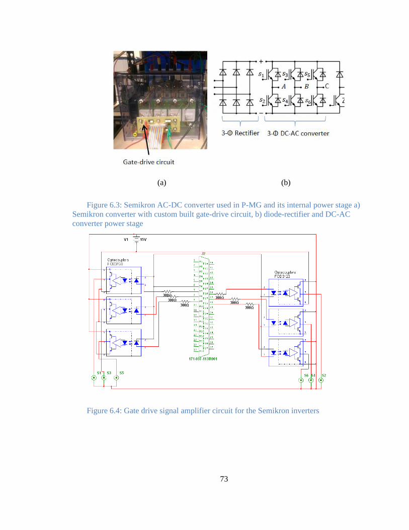
73
(a) (b)
Figure 6.3: Semikron AC-DC converter used in P-MG and its internal power stage a)
Semikron converter with custom built gate-drive circuit, b) diode-rectifier and DC-AC
converter power stage
Figure 6.4: Gate drive signal amplifier circuit for the Semikron inverters
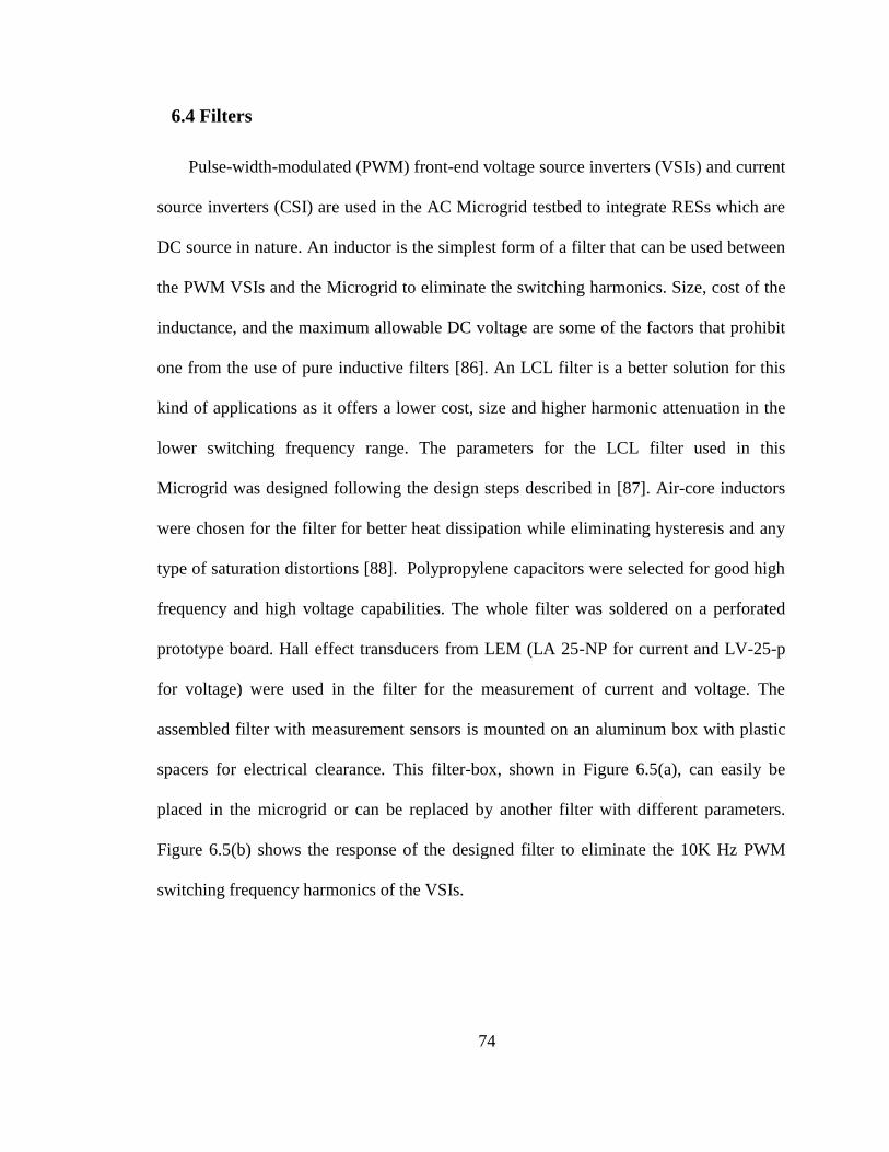
74
6.4 Filters
Pulse-width-modulated (PWM) front-end voltage source inverters (VSIs) and current
source inverters (CSI) are used in the AC Microgrid testbed to integrate RESs which are
DC source in nature. An inductor is the simplest form of a filter that can be used between
the PWM VSIs and the Microgrid to eliminate the switching harmonics. Size, cost of the
inductance, and the maximum allowable DC voltage are some of the factors that prohibit
one from the use of pure inductive filters [86]. An LCL filter is a better solution for this
kind of applications as it offers a lower cost, size and higher harmonic attenuation in the
lower switching frequency range. The parameters for the LCL filter used in this
Microgrid was designed following the design steps described in [87]. Air-core inductors
were chosen for the filter for better heat dissipation while eliminating hysteresis and any
type of saturation distortions [88]. Polypropylene capacitors were selected for good high
frequency and high voltage capabilities. The whole filter was soldered on a perforated
prototype board. Hall effect transducers from LEM (LA 25-NP for current and LV-25-p
for voltage) were used in the filter for the measurement of current and voltage. The
assembled filter with measurement sensors is mounted on an aluminum box with plastic
spacers for electrical clearance. This filter-box, shown in Figure 6.5(a), can easily be
placed in the microgrid or can be replaced by another filter with different parameters.
Figure 6.5(b) shows the response of the designed filter to eliminate the 10K Hz PWM
switching frequency harmonics of the VSIs.
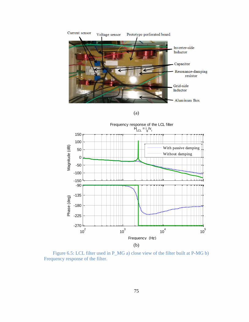
75
(a)
(b)
Figure 6.5: LCL filter used in P_MG a) close view of the filter built at P-MG b)
Frequency response of the filter.
-150
-100
-50
0
50
100
150
Magnitu
de (
dB
)
102
103
104
105
-270
-225
-180
-135
-90
Phase (
deg)
Frequency response of the LCL filter H
LCL = i
g/v
i
Frequency (Hz)
With passive damping
Without damping
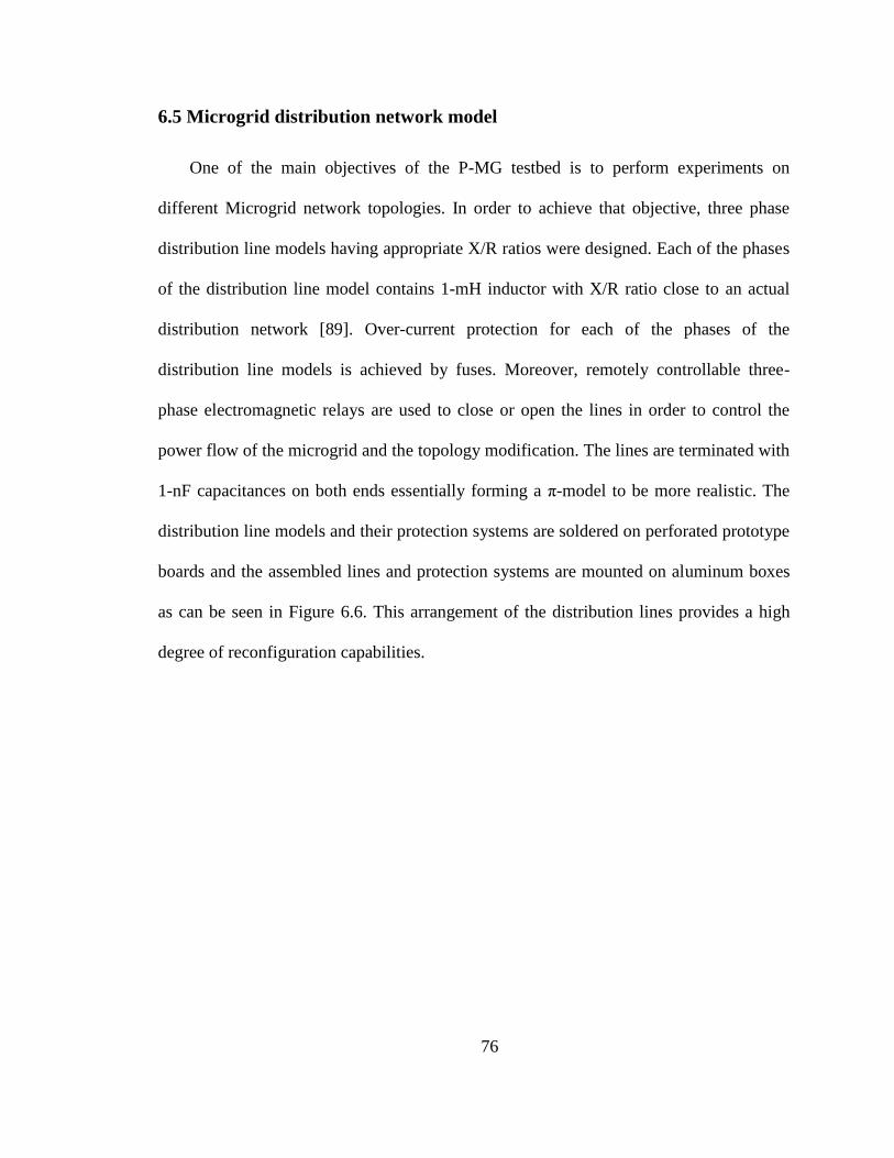
76
6.5 Microgrid distribution network model
One of the main objectives of the P-MG testbed is to perform experiments on
different Microgrid network topologies. In order to achieve that objective, three phase
distribution line models having appropriate X/R ratios were designed. Each of the phases
of the distribution line model contains 1-mH inductor with X/R ratio close to an actual
distribution network [89]. Over-current protection for each of the phases of the
distribution line models is achieved by fuses. Moreover, remotely controllable three-
phase electromagnetic relays are used to close or open the lines in order to control the
power flow of the microgrid and the topology modification. The lines are terminated with
1-nF capacitances on both ends essentially forming a π-model to be more realistic. The
distribution line models and their protection systems are soldered on perforated prototype
boards and the assembled lines and protection systems are mounted on aluminum boxes
as can be seen in Figure 6.6. This arrangement of the distribution lines provides a high
degree of reconfiguration capabilities.
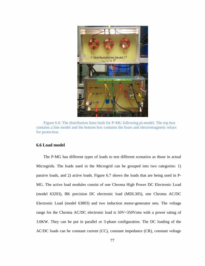
77
Figure 6.6: The distribution lines built for P-MG following pi-model. The top box
contains a line model and the bottom box contains the fuses and electromagnetic relays
for protection.
6.6 Load model
The P-MG has different types of loads to test different scenarios as those in actual
Microgrids. The loads used in the Microgrid can be grouped into two categories: 1)
passive loads, and 2) active loads. Figure 6.7 shows the loads that are being used in P-
MG. The active load modules consist of one Chroma High Power DC Electronic Load
(model 63203), BK precision DC electronic load (MDL305), one Chroma AC/DC
Electronic Load (model 63803) and two induction motor-generator sets. The voltage
range for the Chroma AC/DC electronic load is 50V~350Vrms with a power rating of
3.6KW. They can be put in parallel or 3-phase configuration. The DC loading of the
AC/DC loads can be constant current (CC), constant impedance (CR), constant voltage
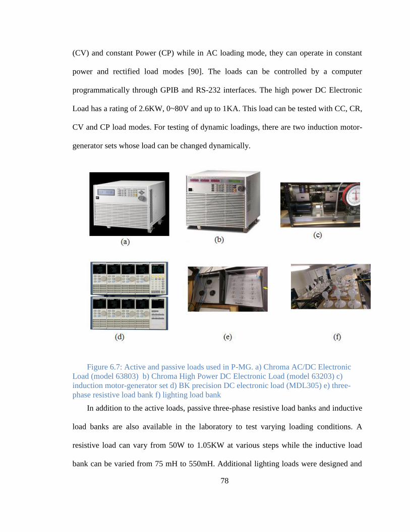
78
(CV) and constant Power (CP) while in AC loading mode, they can operate in constant
power and rectified load modes [90]. The loads can be controlled by a computer
programmatically through GPIB and RS-232 interfaces. The high power DC Electronic
Load has a rating of 2.6KW, 0~80V and up to 1KA. This load can be tested with CC, CR,
CV and CP load modes. For testing of dynamic loadings, there are two induction motor-
generator sets whose load can be changed dynamically.
Figure 6.7: Active and passive loads used in P-MG. a) Chroma AC/DC Electronic
Load (model 63803) b) Chroma High Power DC Electronic Load (model 63203) c)
induction motor-generator set d) BK precision DC electronic load (MDL305) e) three-
phase resistive load bank f) lighting load bank
In addition to the active loads, passive three-phase resistive load banks and inductive
load banks are also available in the laboratory to test varying loading conditions. A
resistive load can vary from 50W to 1.05KW at various steps while the inductive load
bank can be varied from 75 mH to 550mH. Additional lighting loads were designed and
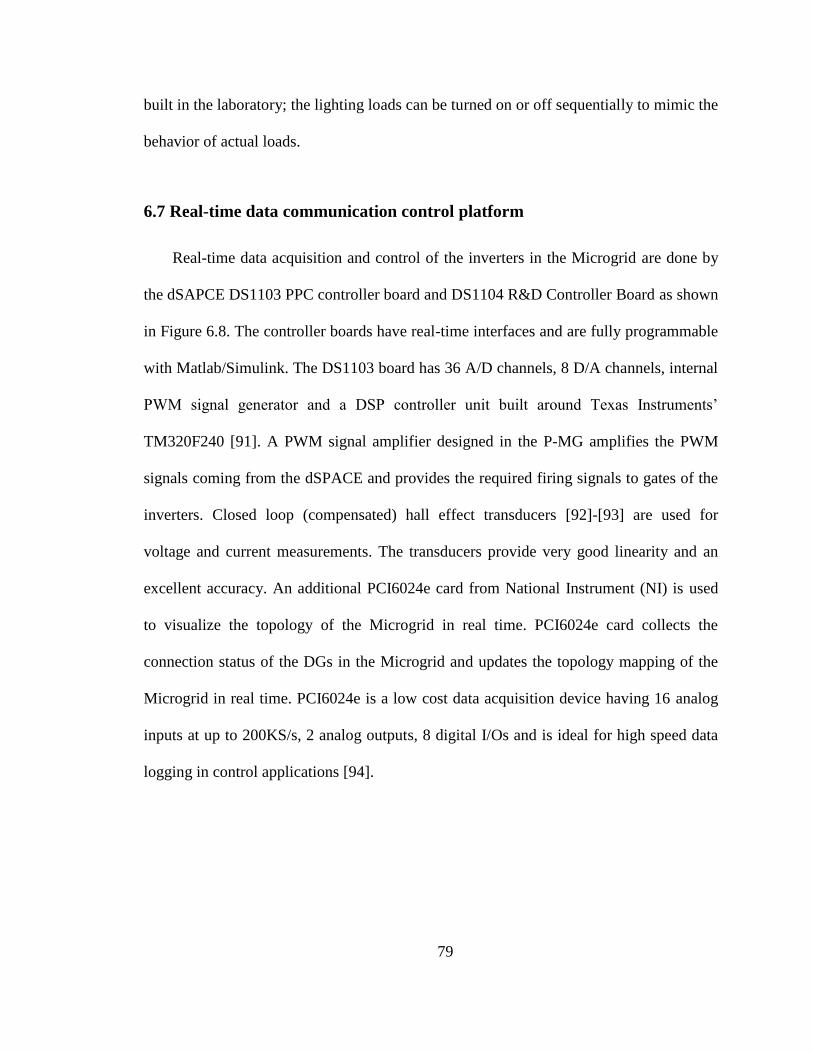
79
built in the laboratory; the lighting loads can be turned on or off sequentially to mimic the
behavior of actual loads.
6.7 Real-time data communication control platform
Real-time data acquisition and control of the inverters in the Microgrid are done by
the dSAPCE DS1103 PPC controller board and DS1104 R&D Controller Board as shown
in Figure 6.8. The controller boards have real-time interfaces and are fully programmable
with Matlab/Simulink. The DS1103 board has 36 A/D channels, 8 D/A channels, internal
PWM signal generator and a DSP controller unit built around Texas Instruments’
TM320F240 [91]. A PWM signal amplifier designed in the P-MG amplifies the PWM
signals coming from the dSPACE and provides the required firing signals to gates of the
inverters. Closed loop (compensated) hall effect transducers [92]-[93] are used for
voltage and current measurements. The transducers provide very good linearity and an
excellent accuracy. An additional PCI6024e card from National Instrument (NI) is used
to visualize the topology of the Microgrid in real time. PCI6024e card collects the
connection status of the DGs in the Microgrid and updates the topology mapping of the
Microgrid in real time. PCI6024e is a low cost data acquisition device having 16 analog
inputs at up to 200KS/s, 2 analog outputs, 8 digital I/Os and is ideal for high speed data
logging in control applications [94].
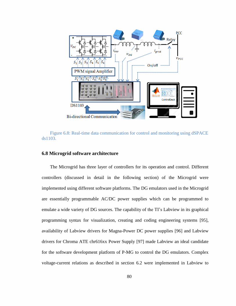
80
Figure 6.8: Real-time data communication for control and monitoring using dSPACE
ds1103.
6.8 Microgrid software architecture
The Microgrid has three layer of controllers for its operation and control. Different
controllers (discussed in detail in the following section) of the Microgrid were
implemented using different software platforms. The DG emulators used in the Microgrid
are essentially programmable AC/DC power supplies which can be programmed to
emulate a wide variety of DG sources. The capability of the TI’s Labview in its graphical
programming syntax for visualization, creating and coding engineering systems [95],
availability of Labview drivers for Magna-Power DC power supplies [96] and Labview
drivers for Chroma ATE chr616xx Power Supply [97] made Labview an ideal candidate
for the software development platform of P-MG to control the DG emulators. Complex
voltage-current relations as described in section 6.2 were implemented in Labview to
81
mimic the behavior of DG sources. Separate Graphical User Interfaces (GUIs) were
developed for each of the DGs. The initial design, tuning and verification of the
controllers for the inverters were done in Matlab/Simulink environment with off-line
simulation. Then the designed controllers were converted to C-programming code which
was then compiled and built in order to be compatible with ControlDesk of dSPACE.
ControlDesk is the dSPACE’s modular experimental and instrumentation software for
electronic control unit (ECU) development [98]. Using the DS 1103 or DS 1104 boards
for data acquisition, ControlDesk performs real-time computations on the developed
controller, computes the necessary control signals and transmits again the computed
control signals in real-time to the physical systems. A graphical user interface (GUI) built
around ControlDesk allows the user to run the inverters in standalone, set reference
values, log the measured and calculated data and tune the control parameters. Software,
called Remote Monitor (RM), is also developed to remotely monitor the performance and
topology of the Microgrid. The RM program can take relay status, different analog values
in real time from different sources and then update the topology mapping of the
Microgrid accordingly. RM was developed in the Labview environment. A summary of
the software architecture developed for the P-MG can be seen in Figure 6.9.
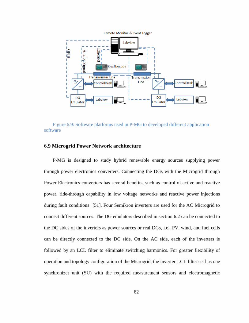
82
Figure 6.9: Software platforms used in P-MG to developed different application
software
6.9 Microgrid Power Network architecture
P-MG is designed to study hybrid renewable energy sources supplying power
through power electronics converters. Connecting the DGs with the Microgrid through
Power Electronics converters has several benefits, such as control of active and reactive
power, ride-through capability in low voltage networks and reactive power injections
during fault conditions [51]. Four Semikron inverters are used for the AC Microgrid to
connect different sources. The DG emulators described in section 6.2 can be connected to
the DC sides of the inverters as power sources or real DGs, i.e., PV, wind, and fuel cells
can be directly connected to the DC side. On the AC side, each of the inverters is
followed by an LCL filter to eliminate switching harmonics. For greater flexibility of
operation and topology configuration of the Microgrid, the inverter-LCL filter set has one
synchronizer unit (SU) with the required measurement sensors and electromagnetic
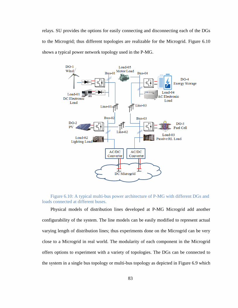
83
relays. SU provides the options for easily connecting and disconnecting each of the DGs
to the Microgrid; thus different topologies are realizable for the Microgrid. Figure 6.10
shows a typical power network topology used in the P-MG.
Figure 6.10: A typical multi-bus power architecture of P-MG with different DGs and
loads connected at different buses.
Physical models of distribution lines developed at P-MG Microgrid add another
configurability of the system. The line models can be easily modified to represent actual
varying length of distribution lines; thus experiments done on the Microgrid can be very
close to a Microgrid in real world. The modularity of each component in the Microgrid
offers options to experiment with a variety of topologies. The DGs can be connected to
the system in a single bus topology or multi-bus topology as depicted in Figure 6.9 which
84
is the typical power architecture for the P-MG. This approach also allows to study
Microgrid clusters where each Microgrid can share power with their neighboring
Microgrid depending on the shortage or surplus of power [99] while maintaining its own
voltage and frequency. In order to perform studies on hybrid AC/DC microgrid systems,
a DC microgrid development program has been initiated at the P-MG laboratory.
6.10 Microgrid control architecture
Microgrids are small scale power systems having the capability of operating in grid
connected modes or islanded modes with DGs, and ESS as power sources which are
connected to the loads distributed in a small geographical area through distribution lines
[100]-[101]. One of the future electric power system (EPS) requirements will be to
ensure Microgrids can operate in an islanded mode from the main grid powering the
islanded EPSs [102]. The P-MG is designed to study plausible scenarios that can occur in
a real situation of future EPSs. The following section describes the control algorithms
used for operation of the converters and the microgrid.
6.10.1 Control of the converters
There are three modes of operation for the converters in a P-MG: 1) grid forming, 2)
grid feeding, and 3) grid supporting [103]. Grid forming converters are more like ideal
voltage sources with low output impedance with controllable output voltages and
frequencies. Grid forming converters are essential for islanded mode of operation.
Several grid forming inverters can operate in parallel, such as in droop control described
later in this section, or one grid forming converter can be used to set the reference voltage
85
and frequency for rest of the Microgrid such as in master-slave mode of operation. The
grid feeding inverters are current sources with high parallel output impedance. These
inverters can inject pre-specified real and reactive powers into the Microgrid with no
control over the voltage and frequency. Hence they cannot operate in stand-alone mode
and require at least one grid-forming inverter in the microgrid. The operation of grid-
supporting inverters is basically in-between the grid-forming inverters and grid-feeding
inverters. They act like current sources to supply active and reactive powers with voltage
and frequency regulatory functions. They can adjust their real and reactive power set
point to support the voltage and frequency of the Microgrid.
Low level controllers such as voltage controllers and current controllers described in
Chapter 4 are responsible for controlling the local output variables, i.e., voltage, current
and frequency. These controllers have high bandwidths and fast response times. Higher
level controllers are required to maintain stability of the system as well as proper power
sharing of the DGs.
6.10.2 Control of the Microgrid
Large percentage of renewable energy source integration into a system requires an
accurate control of voltage and frequency for reliability and stability purpose[104].
Proper sharing of real and reactive powers among DGs connected to the Microgrid is one
of the major objectives of the Microgrid operation. The controllers that can achieve that
objective can be classified into three groups: droop control, centralized control, and
distributed control. Droop control is the most popular controller used for Microgrid
operation due to the benefits of higher reliability and no requirements of communication
86
networks. The primary power sharing controller used in P-MG is the droop-based
controller described in Chapter 4. Voltage-Var droop control ensures that the more a DG
supplies reactive power to the network, the more the voltage set point for that DG is
reduced. Properly selected droop parameter also reduces the circulating current among
the parallel DGs connected to the Microgrid [104]. The real power-frequency droop
enables the DGs to share real power proportional to the frequency-active power droop
parameter.
6.10.3 Phase-locked-loop (PLL) and Synchronization
Synchronization is an important aspect in the accurate operation of Microgrids both
in grid-connected mode and islanded mode. The controllers for the grid-feeding and grid-
supporting inverters require accurate information about the voltage and frequency of the
Microgrid or the grid in order to inject power to the system. Connection and
disconnection of the inverters from the grid also demand precise information on the grid.
During a synchronization process, the voltage, frequency and voltage angle of the
incoming inverter are slowly changed to synchronize with the point of common coupling
(PCC). A running-average filter (RAF) based enhanced phase-locked loop (E-PLL) was
developed for the synchronizer used in P-MG. Figure 6.11 shows the details of the
designed E-PLL.
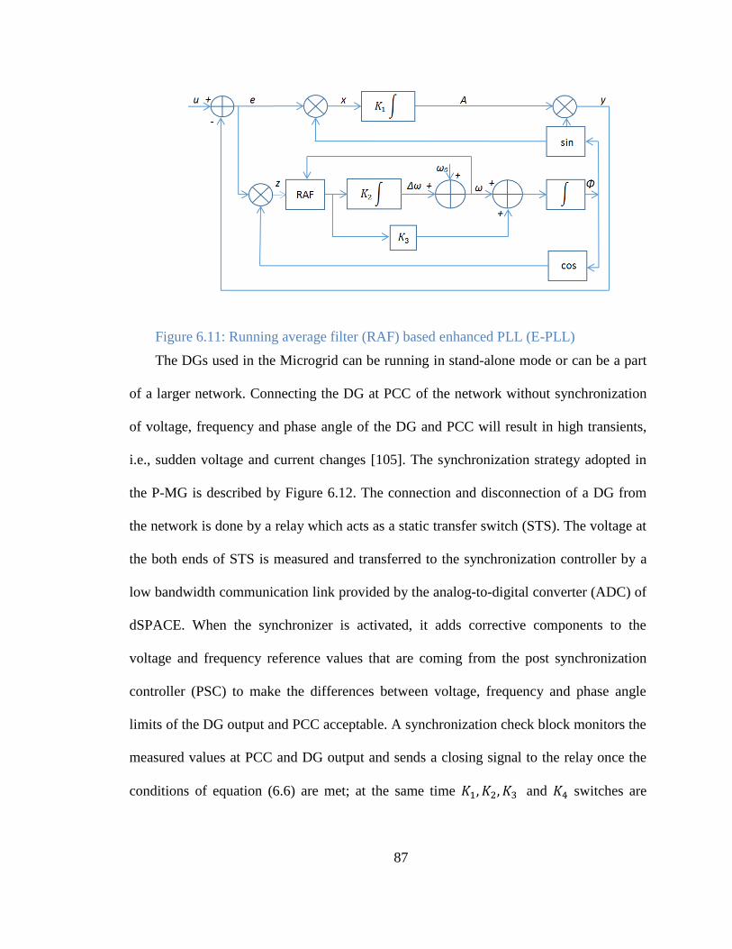
87
Figure 6.11: Running average filter (RAF) based enhanced PLL (E-PLL)
The DGs used in the Microgrid can be running in stand-alone mode or can be a part
of a larger network. Connecting the DG at PCC of the network without synchronization
of voltage, frequency and phase angle of the DG and PCC will result in high transients,
i.e., sudden voltage and current changes [105]. The synchronization strategy adopted in
the P-MG is described by Figure 6.12. The connection and disconnection of a DG from
the network is done by a relay which acts as a static transfer switch (STS). The voltage at
the both ends of STS is measured and transferred to the synchronization controller by a
low bandwidth communication link provided by the analog-to-digital converter (ADC) of
dSPACE. When the synchronizer is activated, it adds corrective components to the
voltage and frequency reference values that are coming from the post synchronization
controller (PSC) to make the differences between voltage, frequency and phase angle
limits of the DG output and PCC acceptable. A synchronization check block monitors the
measured values at PCC and DG output and sends a closing signal to the relay once the
conditions of equation (6.6) are met; at the same time and switches are
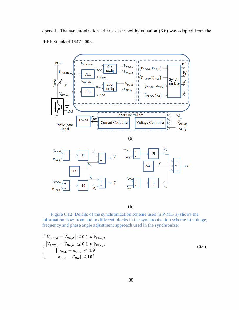
88
opened. The synchronization criteria described by equation (6.6) was adopted from the
IEEE Standard 1547-2003.
(a)
(b)
Figure 6.12: Details of the synchronization scheme used in P-MG a) shows the
information flow from and to different blocks in the synchronization scheme b) voltage,
frequency and phase angle adjustment approach used in the synchronizer
{
| |
| |
| |
| |
(6.6)

89
where , , , are the d-axis voltage at PCC, d-axis voltage of the
DG, q-axis voltage of PCC, q-axis voltage of the DG, respectively. and are the
frequency of the voltage at PCC and the frequency of DG output voltage, respectively.
And are the phase angle of the voltage at PCC and the phase angle of DG
output voltage respectively.
90
Chapter 7
Experimental Verification
The purpose of the P-MG is to study various aspects of renewable energy integration
through power electronic interfaces, microgrid operation under various scenarios and
energy management of microgrid. The high degree of reconfiguration capabilities and
easy access to almost all hardware and software components of the system make the P-
MG setup an ideal platform for control strategy verification, microgrid optimization
algorithm evaluation and microgrid topology planning. To demonstrate that the designed
P-MG can perform these tasks, several experimental tests were performed on the
microgrid. Figure 7.1 shows the ring-bus topology of the microgrid that was used to carry
out several experiments:
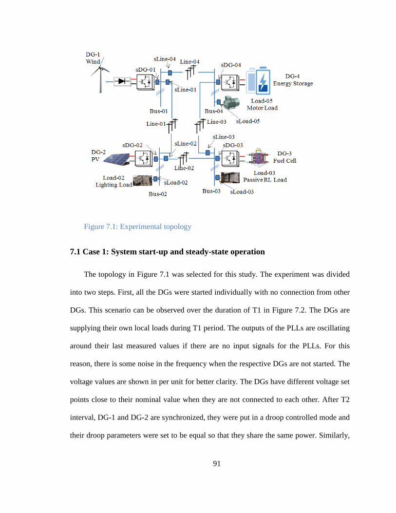
91
Figure 7.1: Experimental topology
7.1 Case 1: System start-up and steady-state operation
The topology in Figure 7.1 was selected for this study. The experiment was divided
into two steps. First, all the DGs were started individually with no connection from other
DGs. This scenario can be observed over the duration of T1 in Figure 7.2. The DGs are
supplying their own local loads during T1 period. The outputs of the PLLs are oscillating
around their last measured values if there are no input signals for the PLLs. For this
reason, there is some noise in the frequency when the respective DGs are not started. The
voltage values are shown in per unit for better clarity. The DGs have different voltage set
points close to their nominal value when they are not connected to each other. After T2
interval, DG-1 and DG-2 are synchronized, they were put in a droop controlled mode and
their droop parameters were set to be equal so that they share the same power. Similarly,
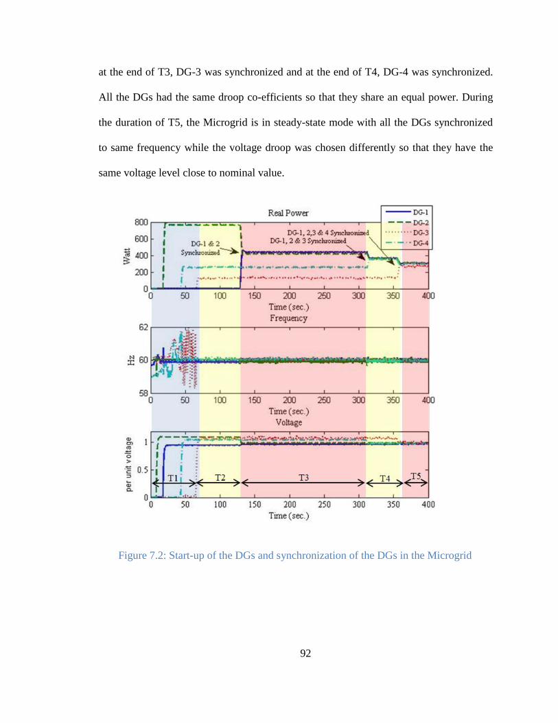
92
at the end of T3, DG-3 was synchronized and at the end of T4, DG-4 was synchronized.
All the DGs had the same droop co-efficients so that they share an equal power. During
the duration of T5, the Microgrid is in steady-state mode with all the DGs synchronized
to same frequency while the voltage droop was chosen differently so that they have the
same voltage level close to nominal value.
Figure 7.2: Start-up of the DGs and synchronization of the DGs in the Microgrid
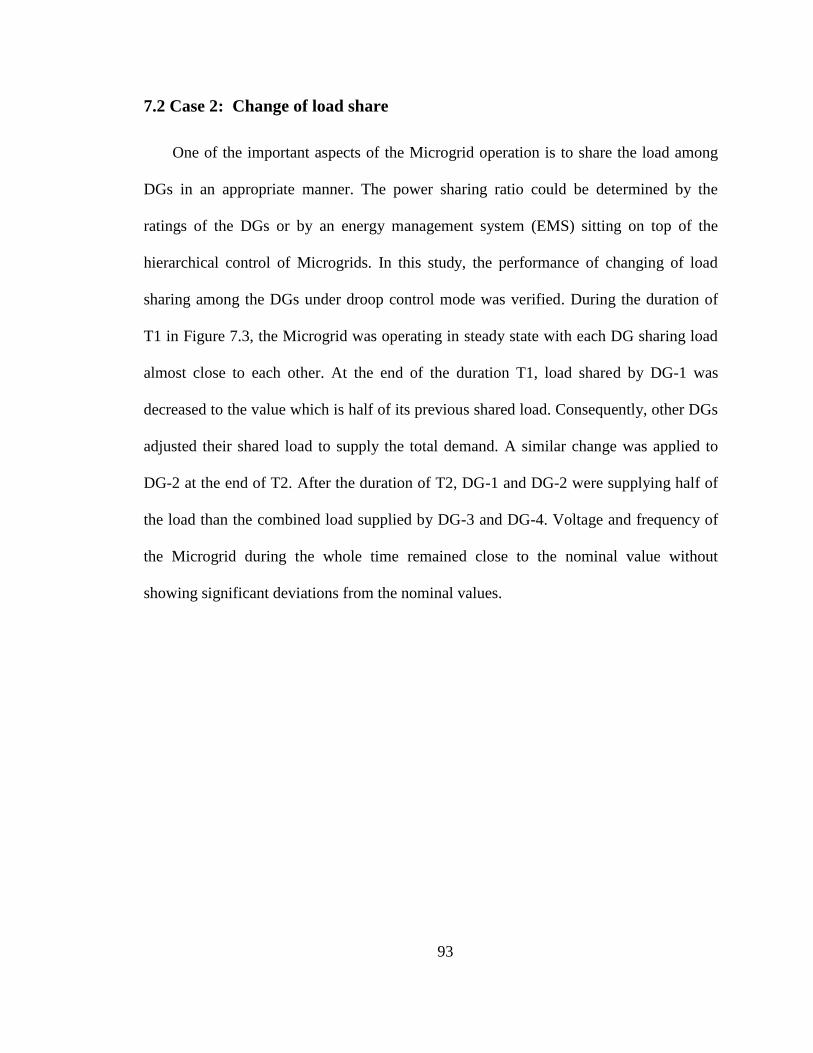
93
7.2 Case 2: Change of load share
One of the important aspects of the Microgrid operation is to share the load among
DGs in an appropriate manner. The power sharing ratio could be determined by the
ratings of the DGs or by an energy management system (EMS) sitting on top of the
hierarchical control of Microgrids. In this study, the performance of changing of load
sharing among the DGs under droop control mode was verified. During the duration of
T1 in Figure 7.3, the Microgrid was operating in steady state with each DG sharing load
almost close to each other. At the end of the duration T1, load shared by DG-1 was
decreased to the value which is half of its previous shared load. Consequently, other DGs
adjusted their shared load to supply the total demand. A similar change was applied to
DG-2 at the end of T2. After the duration of T2, DG-1 and DG-2 were supplying half of
the load than the combined load supplied by DG-3 and DG-4. Voltage and frequency of
the Microgrid during the whole time remained close to the nominal value without
showing significant deviations from the nominal values.
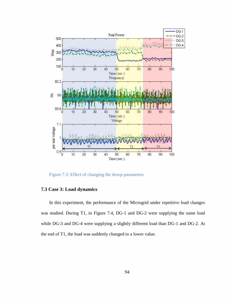
94
Figure 7.3: Effect of changing the droop parameters
7.3 Case 3: Load dynamics
In this experiment, the performance of the Microgrid under repetitive load changes
was studied. During T1, in Figure 7.4, DG-1 and DG-2 were supplying the same load
while DG-3 and DG-4 were supplying a slightly different load than DG-1 and DG-2. At
the end of T1, the load was suddenly changed to a lower value.
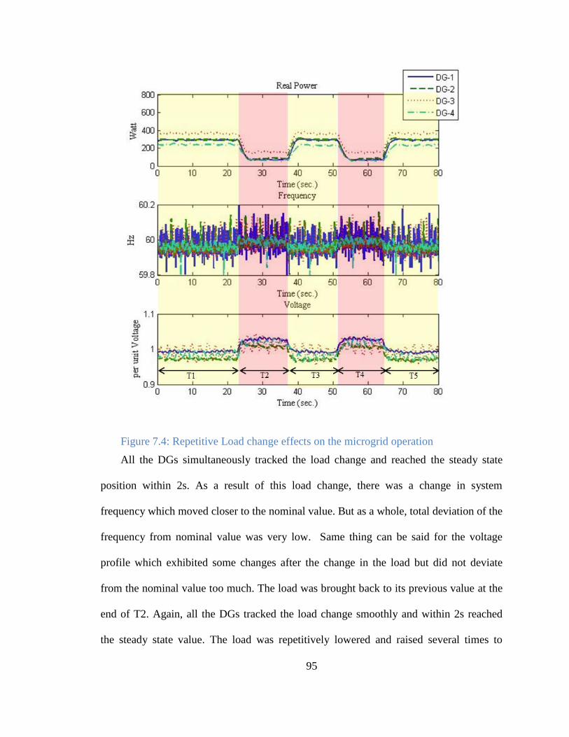
95
Figure 7.4: Repetitive Load change effects on the microgrid operation
All the DGs simultaneously tracked the load change and reached the steady state
position within 2s. As a result of this load change, there was a change in system
frequency which moved closer to the nominal value. But as a whole, total deviation of the
frequency from nominal value was very low. Same thing can be said for the voltage
profile which exhibited some changes after the change in the load but did not deviate
from the nominal value too much. The load was brought back to its previous value at the
end of T2. Again, all the DGs tracked the load change smoothly and within 2s reached
the steady state value. The load was repetitively lowered and raised several times to
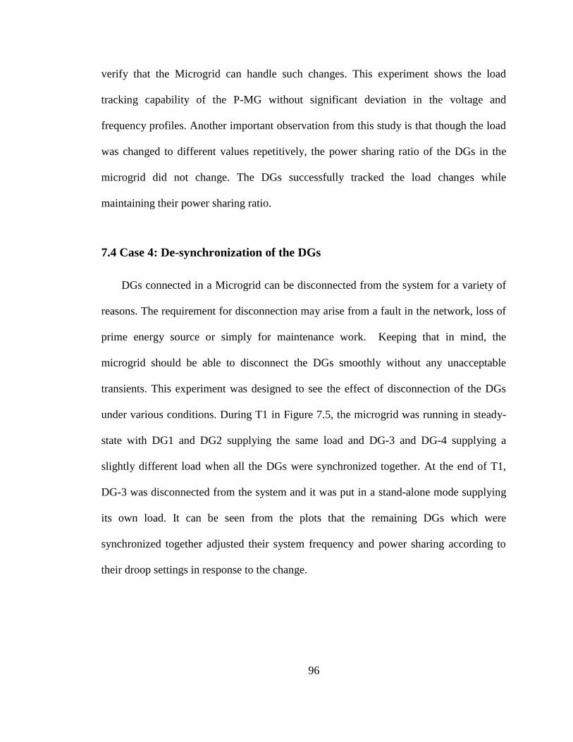
96
verify that the Microgrid can handle such changes. This experiment shows the load
tracking capability of the P-MG without significant deviation in the voltage and
frequency profiles. Another important observation from this study is that though the load
was changed to different values repetitively, the power sharing ratio of the DGs in the
microgrid did not change. The DGs successfully tracked the load changes while
maintaining their power sharing ratio.
7.4 Case 4: De-synchronization of the DGs
DGs connected in a Microgrid can be disconnected from the system for a variety of
reasons. The requirement for disconnection may arise from a fault in the network, loss of
prime energy source or simply for maintenance work. Keeping that in mind, the
microgrid should be able to disconnect the DGs smoothly without any unacceptable
transients. This experiment was designed to see the effect of disconnection of the DGs
under various conditions. During T1 in Figure 7.5, the microgrid was running in steady-
state with DG1 and DG2 supplying the same load and DG-3 and DG-4 supplying a
slightly different load when all the DGs were synchronized together. At the end of T1,
DG-3 was disconnected from the system and it was put in a stand-alone mode supplying
its own load. It can be seen from the plots that the remaining DGs which were
synchronized together adjusted their system frequency and power sharing according to
their droop settings in response to the change.
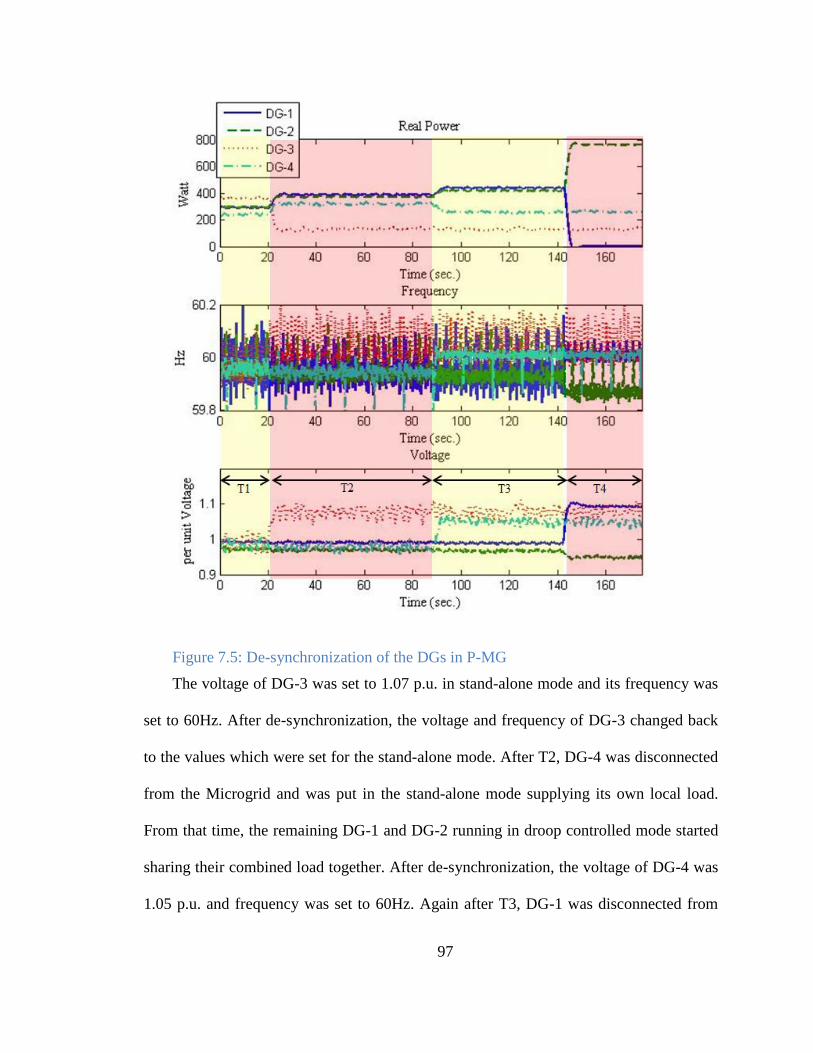
97
Figure 7.5: De-synchronization of the DGs in P-MG
The voltage of DG-3 was set to 1.07 p.u. in stand-alone mode and its frequency was
set to 60Hz. After de-synchronization, the voltage and frequency of DG-3 changed back
to the values which were set for the stand-alone mode. After T2, DG-4 was disconnected
from the Microgrid and was put in the stand-alone mode supplying its own local load.
From that time, the remaining DG-1 and DG-2 running in droop controlled mode started
sharing their combined load together. After de-synchronization, the voltage of DG-4 was
1.05 p.u. and frequency was set to 60Hz. Again after T3, DG-1 was disconnected from

98
the Microgrid. DG-1 does not have its local load, so its output power was reduced to
zero, output voltage was 1.08 and output frequency was 60Hz after the de-
synchronization. From that point on, DG-2 was supplying the load in droop mode. Hence,
there is a frequency deviation coming from the droop setting for DG-2 after T4.
7.5 Case 5: Power network topology Reconfiguration
In a practical microgrid operation, power network topology should be reconfigurable
to serve loads from different sources through different power network branches under
various conditions. In this experiment, topology reconfiguration was considered which
demonstrates the high degree of flexibility and re-configurability of P-MG. Initially the
microgrid was running in radial bus formation by opening the switch sLine-01 (Figure
7.1). Duration T1 Figure 7.6 shows the current flowing through line-04 under this radial
configuration. The network topology was then changed to a ring bus formation at the end
of T1 by closing the switch sLine-01. Both lines Line-01 and Line-04 connect BUS-01 to
the system and there is no local load connected to the BUS-01. Hence current through
Line-04 was reduced when the topology was changed from radial network to ring bus
network formation as some of the power from DG-1 was being delivered through Line-
01. This scenario is evident from Figure 7.6 during T2. At this time, current through
Line-04 was less than that of the case during T1. At the end of T2, sLine-01 switch was
again openned to form the radial network. As a result of this topology change the current
through Line-04 increased during T3.
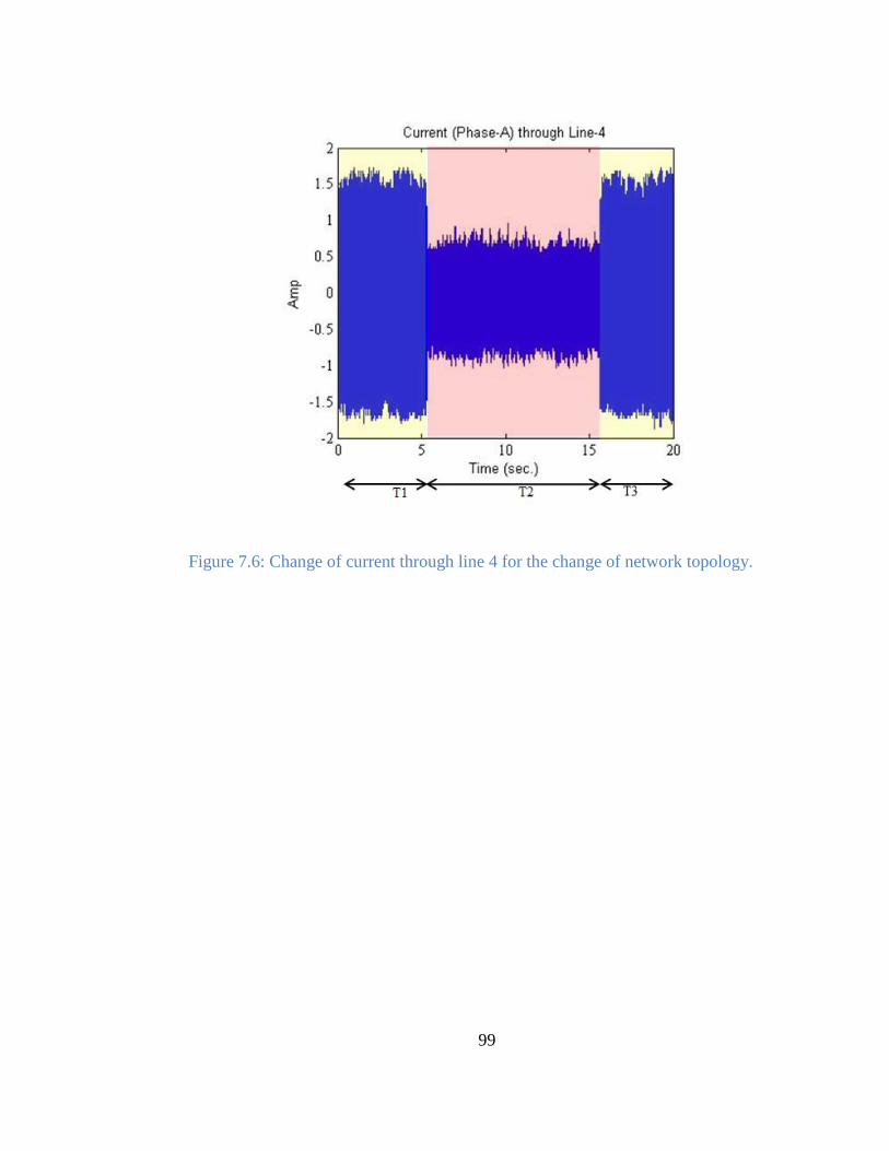
99
Figure 7.6: Change of current through line 4 for the change of network topology.

100
Chapter 8
Future work and conclusion
This work reveals the impact of cooperative control strategies on the modernization
of future microgrids. Microgrids provide the opportunity to integrate a variety of
renewable energy sources and conventional fossil-fuel sources in a local energy network
to significantly boost efficiency. Therefore, they have the potential to be the basic core
technology that will make up the entire future power grid.
Future Work:
A possible future for a smart power grid, could be the combination of clusters of
micro-grids. Many studies have been performed on the stand-alone and grid-tied micro-
grids, which prove that these systems tend to work well independently. However, when
they are combined to form clusters of micro-grid systems, many unexpected behaviors
can occur. Creating a resilient, reliable, and safe smart grid thus requires the capability to
test how systems perform and interact prior to deployment in practical operating
environments. Realistic test environments can fill this role.
Testbeds are essentially platforms for the demanding and replicable testing of
theories, computational tools, new technologies, and systems. The micro-grid testbed

101
provides a development environment without the potential hazards or consequences
present when testing in a real scale production environment. A testbed can be used to
demonstrate new components or entire systems, and can include software and hardware
/physical equipment as well as networking components.
As mentioned earlier, during this project a laboratory setup for a typical AC/DC
microgrid system was developed. Although this setup has been used to study some
control aspects and issues related to power management of the microgrid systems, there is
still more to investigate. Some of the limitations of the P-MG systems can be summarized
as follows:
Uni-direction power flow between the AC and DC part of the hybrid AC/DC
microgrid.
Grid connectivity has been neglected in this study. Therefore, the system is
always operating off the grid.
The grid size is limited to 4-bus system in both AC and DC system.
Hence, improving these limitations could be the potential tasks for future researchers
to be addressed. Additionally, the other aspects of the power grid to be studied are as
follows:
i. Islanding in microgrid: In an islanded microgrid operation, DGs continue to
power the loads located in the microgrid without requiring to obtain power from
the utility grid.
ii. Cyber security analysis: The U.S. Department of Homeland Security (DHS)
reports that cyber-attacks on the electric power grid are enormously increasing.

102
Concern over the possibility of hacking into power grid software and disruption in
the electrical supply system is growing because such an attack could be one of the
quickest ways to mark irreversible economic and environmental impacts.
iii. Reliability analysis and evaluation of microgrids: For microgrid owners, there are
insurers who will cover losses for some types of equipment and systems. But
there are currently no insurance policies that will cover the mis-performance of
the entire microgrid. That suggests a need to uncover some of the complexities
associated with the resilience of microgrids.
iv. Data visualization and management using the phasor measurement units (PMU):
Due to recent installation of the PMUs in the power grids, one major component
of this research is management and analysis of big data.
v. Construction and development of clusters of microgrids: Development of clusters
of microgrids shared between multiple universities and research centers will
provide a platform to develop a practical solution for uncertainties, components’
failure and cyber-attacks in a typical smart grid.
vi. Stability analysis of microgrid: Stability of microgrid is of paramount interest as
microgrids will serve critical loads when employed in real world. Especially the
stability is a big concern when several microgrids are connected together to from
cluster of microgrid.
vii. Energy storage systems (ESS): ESSs are one of the key components of microgrid
operations. In order to effectively manage the intermittent characteristics of RESs,
ESSs are required to provide support to the microgrid.
103
Conclusion
In this study, the performance of droop-based cooperative methodology has been
studied and verified through simulation and experiments. These experiments have been
done on a standalone AC microgrid, DC microgrid and hybrid AC/DC microgrid
systems. The results have proven that the application of the designed methodology
provides a promising solution to the realization of the resilient and intelligent microgrids.
Since the term “microgrid” has still a vague definition in the vocabulary of power
systems engineering and the standards are yet to be fully developed, further improvement
of this approach can drive the microgrid evolution one step forward.
104
References
[1] R. H. Lasseter, “MicroGrids,” in 2002 IEEE Power Engineering Society Winter
Meeting. Conference Proceedings (Cat. No.02CH37309), vol. 1, pp. 305–308,
2002.
[2] S. M. Ashabani and Y. A. I. Mohamed, “New Family of Microgrid Control and
Management Strategies in Smart Distribution Grids—Analysis, Comparison and
Testing,” IEEE Trans. Power Syst., vol. 29, no. 5, pp. 2257–2269, Sep. 2014.
[3] A. Kwasinski, “Quantitative Evaluation of DC Microgrids Availability: Effects of
System Architecture and Converter Topology Design Choices,” IEEE Trans.
Power Electron., vol. 26, no. 3, pp. 835–851, Mar. 2011.
[4] T. Dragicevic, J. C. Vasquez, J. M. Guerrero, and D. Skrlec, “Advanced LVDC
Electrical Power Architectures and Microgrids: A step toward a new generation of
power distribution networks.,” IEEE Electrif. Mag., vol. 2, no. 1, pp. 54–65, Mar.
2014.
[5] S. Anand and B. G. Fernandes, “Optimal voltage level for DC microgrids,” in
IECON - 36th Annual Conference on IEEE Industrial Electronics Society, 2010,
pp. 3034–3039, 2010.
[6] J.-D. Park and J. Candelaria, “Fault Detection and Isolation in Low-Voltage DC-
Bus Microgrid System,” IEEE Trans. Power Deliv., vol. 28, no. 2, pp. 779–787,
Apr. 2013.
105
[7] R. Salcedo, A. Bokhari, M. Diaz-Aguilo, N. Lin, T. Hong, F. de Leon, D.
Czarkowski, S. Flank, A. McDonnell, and R. E. Uosef, “Benefits of a
Nonsynchronous Microgrid on Dense-Load LV Secondary Networks,” IEEE
Trans. Power Deliv., vol. 31, no. 3, pp. 1076–1084, Jun. 2016.
[8] P. C. Loh and F. Blaabjerg, “Autonomous operation of hybrid microgrid with AC
and DC sub-grids,” pp. 1–10.
[9] X. Liu, P. Wang, and P. C. Loh, “A Hybrid AC/DC Microgrid and Its
Coordination Control,” IEEE Trans. Smart Grid, vol. 2, no. 2, pp. 278–286, Jun.
2011.
[10] T.-P. Chen, “Zero-Sequence Circulating Current Reduction Method for Parallel
HEPWM Inverters Between AC Bus and DC Bus,” IEEE Trans. Ind. Electron.,
vol. 59, no. 1, pp. 290–300, Jan. 2012.
[11] Z. Jiang and Xunwei Yu, “Power electronics interfaces for hybrid DC and AC-
linked microgrids,” in 2009 IEEE 6th International Power Electronics and Motion
Control Conference, 2009, pp. 730–736.
[12] J. M. Guerrero, J. C. Vasquez, J. Matas, L. G. de Vicuna, and M. Castilla,
“Hierarchical Control of Droop-Controlled AC and DC Microgrids—A General
Approach Toward Standardization,” IEEE Trans. Ind. Electron., vol. 58, no. 1, pp.
158–172, Jan. 2011.
[13] V. Nasirian, S. Moayedi, A. Davoudi, and F. L. Lewis, “Distributed Cooperative
Control of DC Microgrids,” IEEE Trans. Power Electron., vol. 30, no. 4, pp.
2288–2303, Apr. 2015.
106
[14] S. Anand and B. G. Fernandes, “Optimal voltage level for DC microgrids,” in
IECON 2010 - 36th Annual Conference on IEEE Industrial Electronics Society,
2010, pp. 3034–3039.
[15] S. Anand, B. G. Fernandes, and J. Guerrero, “Distributed Control to Ensure
Proportional Load Sharing and Improve Voltage Regulation in Low-Voltage DC
Microgrids,” IEEE Trans. Power Electron., vol. 28, no. 4, pp. 1900–1913, Apr.
2013.
[16] K. Mets, T. Verschueren, F. De Turck, and C. Develder, “Exploiting V2G to
optimize residential energy consumption with electrical vehicle (dis)charging,” in
2011 IEEE First International Workshop on Smart Grid Modeling and Simulation
(SGMS), 2011, pp. 7–12.
[17] R. Yu, J. Ding, W. Zhong, Y. Liu, and S. Xie, “PHEV Charging and Discharging
Cooperation in V2G Networks: A Coalition Game Approach,” IEEE Internet
Things J., vol. 1, no. 6, pp. 578–589, Dec. 2014.
[18] S. W. Hadley, “Evaluating the impact of Plug-in Hybrid Electric Vehicles on
regional electricity supplies,” in 2007 iREP Symposium - Bulk Power System
Dynamics and Control - VII. Revitalizing Operational Reliability, 2007, pp. 1–12.
[19] T. Ma, S. Member, and O. A. Mohammed, “Optimal Charging of Plug-in Electric
Vehicles for a Car-Park Infrastructure,” vol. 50, no. 4, pp. 2323–2330, 2014.
[20] C. Chen and S. Duan, “Optimal Integration of Plug-In Hybrid Electric Vehicles in
Microgrids,” IEEE Trans. Ind. Informatics, vol. 10, no. 3, pp. 1917–1926, Aug.
2014.
107
[21] V. Nasirian, A. Davoudi, F. L. Lewis, and J. M. Guerrero, “Distributed Adaptive
Droop Control for DC Distribution Systems,” IEEE Trans. Energy Convers., vol.
29, no. 4, pp. 944–956, Dec. 2014.
[22] S. Bashash, S. J. Moura, J. C. Forman, and H. K. Fathy, “Plug-in hybrid electric
vehicle charge pattern optimization for energy cost and battery longevity,” J.
Power Sources, vol. 196, no. 1, pp. 541–549, Jan. 2011.
[23] S. Chen, T. Mount, and L. Tong, “Optimizing Operations for Large Scale
Charging of Electric Vehicles,” in 2013 46th Hawaii International Conference on
System Sciences, 2013, pp. 2319–2326.
[24] W. Su and M.-Y. Chow, “Performance evaluation of a PHEV parking station using
Particle Swarm Optimization,” in 2011 IEEE Power and Energy Society General
Meeting, 2011, pp. 1–6.
[25] Y. Gu, X. Xiang, W. Li, and X. He, “Mode-Adaptive Decentralized Control for
Renewable DC Microgrid With Enhanced Reliability and Flexibility,” IEEE
Trans. Power Electron., vol. 29, no. 9, pp. 5072–5080, Sep. 2014.
[26] X. Lu, K. Sun, J. M. Guerrero, J. C. Vasquez, and L. Huang, “Double-Quadrant
State-of-Charge-Based Droop Control Method for Distributed Energy Storage
Systems in Autonomous DC Microgrids,” IEEE Trans. Smart Grid, vol. 6, no. 1,
pp. 147–157, Jan. 2015.
[27] N. Rahbari-Asr and M.-Y. Chow, “Cooperative Distributed Demand Management
for Community Charging of PHEV/PEVs Based on KKT Conditions and
Consensus Networks,” IEEE Trans. Ind. Informatics, vol. PP, no. 3, pp. 1–1, 2014.
108
[28] D. C. Link, V. Sensing, P. Goli, S. Member, W. Shireen, and S. Member, “PV
Integrated Smart Charging of PHEVs Based on,” vol. 5, no. 3, pp. 1421–1428,
2014.
[29] Y. Xu, “Optimal Distributed Charging Rate Control of Plug-In Electric Vehicles
for Demand Management,” IEEE Trans. Power Syst., vol. PP, no. 99, pp. 1–10,
2014.
[30] X. Lu, J. M. Guerrero, K. Sun, J. C. Vasquez, R. Teodorescu, and L. Huang,
“Hierarchical Control of Parallel AC-DC Converter Interfaces for Hybrid
Microgrids,” IEEE Trans. Smart Grid, vol. 5, no. 2, pp. 683–692, Mar. 2014.
[31] J. M. Carrasco, L. G. Franquelo, J. T. Bialasiewicz, E. Galvan, R. C.
PortilloGuisado, M. A. M. Prats, J. I. Leon, and N. Moreno-Alfonso, “Power-
Electronic Systems for the Grid Integration of Renewable Energy Sources: A
Survey,” IEEE Trans. Ind. Electron., vol. 53, no. 4, pp. 1002–1016, Jun. 2006.
[32] B. S. Hartono and R. Setiabudy, “Review of microgrid technology,” in 2013
International Conference on QiR, 2013, pp. 127–132.
[33] F. Blaabjerg, Z. Chen, and S. B. Kjaer, “Power Electronics as Efficient Interface in
Dispersed Power Generation Systems,” IEEE Trans. Power Electron., vol. 19, no.
5, pp. 1184–1194, Sep. 2004.
[34] A. P. Martins, A. S. Carvalho, and A. S. Araujo, “Design and implementation of a
current controller for the parallel operation of standard UPSs,” in Proceedings of
IECON ’95 - 21st Annual Conference on IEEE Industrial Electronics, 1995, vol. 1,
pp. 584–589.
109
[35] R. A. Kaushik and N. M. Pindoriya, “Power flow control of hybrid AC-DC
microgrid using master-slave technique,” in 2014 IEEE Conference on Energy
Conversion (CENCON), 2014, pp. 389–394.
[36] S. T. Cady, A. D. Dominguez-Garcia, and C. N. Hadjicostis, “A Distributed
Generation Control Architecture for Islanded AC Microgrids,” IEEE Trans.
Control Syst. Technol., vol. PP, no. 99, pp. 1–1, 2015.
[37] F. Katiraei and M. R. Iravani, “Power Management Strategies for a Microgrid
With Multiple Distributed Generation Units,” IEEE Trans. Power Syst., vol. 21,
no. 4, pp. 1821–1831, Nov. 2006.
[38] A. G. Tsikalakis and N. D. Hatziargyriou, “Centralized Control for Optimizing
Microgrids Operation,” IEEE Trans. Energy Convers., vol. 23, no. 1, pp. 241–248,
Mar. 2008.
[39] A. N. Venkat, I. A. Hiskens, J. B. Rawlings, and S. J. Wright, “Distributed MPC
Strategies With Application to Power System Automatic Generation Control,”
IEEE Trans. Control Syst. Technol., vol. 16, no. 6, pp. 1192–1206, Nov. 2008.
[40] S. Bolognani and S. Zampieri, “A Distributed Control Strategy for Reactive Power
Compensation in Smart Microgrids,” IEEE Trans. Automat. Contr., vol. 58, no. 11,
pp. 2818–2833, Nov. 2013.
[41] A. Bidram and A. Davoudi, “Hierarchical Structure of Microgrids Control
System,” IEEE Trans. Smart Grid, vol. 3, no. 4, pp. 1963–1976, Dec. 2012.
110
[42] S. Liu, X. Wang, and P. X. Liu, “Impact of Communication Delays on Secondary
Frequency Control in an Islanded Microgrid,” IEEE Trans. Ind. Electron., vol. 62,
no. 4, pp. 2021–2031, Apr. 2015.
[43] M. Savaghebi, A. Jalilian, J. C. Vasquez, and J. M. Guerrero, “Secondary Control
Scheme for Voltage Unbalance Compensation in an Islanded Droop-Controlled
Microgrid,” IEEE Trans. Smart Grid, vol. 3, no. 2, pp. 797–807, Jun. 2012.
[44] B. Dong, Y. Li, Z. Zheng, and L. Xu, “Control strategies of microgrid with Hybrid
DC and AC Buses,” in Power Electronics and Applications (EPE 2011),
Proceedings of the 2011-14th European Conference on, 2011, pp. 1–8.
[45] P. Wang, S. Member, C. Jin, D. Zhu, S. Member, Y. Tang, P. C. Loh, and F. H.
Choo, “Distributed Control for Autonomous Operation of a Three-Port AC / DC /
DS Hybrid Microgrid,” vol. 62, no. 2, pp. 1279–1290, 2015.
[46] N. Eghtedarpour and E. Farjah, “Power control and management in a Hybrid
AC/DC microgrid,” IEEE Trans. Smart Grid, vol. 5, no. 3, pp. 1494–1505, 2014.
[47] P. C. Loh, D. Li, Y. K. Chai, and F. Blaabjerg, “Autonomous control of
interlinking converter with energy storage in hybrid AC-DC microgrid,” IEEE
Trans. Ind. Appl., vol. 49, no. 3, pp. 1374–1382, 2013.
[48] C. Wang, X. Li, L. Guo, and Y. W. Li, “A nonlinear-disturbance-observer-based
DC-Bus voltage control for a hybrid AC/DC microgrid,” IEEE Trans. Power
Electron., vol. 29, no. 11, pp. 6162–6177, 2014.
111
[49] T. S. Ustun, C. Ozansoy, and A. Zayegh, “Recent developments in microgrids and
example cases around the world—A review,” Renew. Sustain. Energy Rev., vol.
15, no. 8, pp. 4030–4041, Oct. 2011.
[50] C. E. Commission, “Certs microgrid laboratory test bed,” Energy, vol. 26, no.
February, pp. 1–8, 2009.
[51] L. Meng, A. Luna, E. Diaz, B. Sun, T. Dragicevic, M. Savaghebi, J. Vasquez, J.
Guerrero, and M. Graells, “Flexible System Integration and Advanced Hierarchical
Control Architectures in the Microgrid Research Laboratory of Aalborg
University,” IEEE Trans. Ind. Appl., vol. 52, no. 2, pp. 1–1, 2015.
[52] B. Zhao, X. Zhang, and J. Chen, “Integrated microgrid laboratory system,” IEEE
Trans. Power Syst., vol. 27, no. 4, pp. 2175–2185, 2012.
[53] V. Salehi, A. Mohamed, A. Mazloomzadeh, and O. A. Mohammed, “Laboratory-
based smart power system, part I: Design and system development,” IEEE Trans.
Smart Grid, vol. 3, no. 3, pp. 1394–1404, 2012.
[54] C. Wang, X. Yang, Z. Wu, Y. Che, L. Guo, S. Zhang, and Y. Liu, “A Highly
Integrated and Reconfigurable Microgrid Testbed with Hybrid Distributed Energy
Sources,” IEEE Trans. Smart Grid, vol. 7, no. 1, pp. 451–459, 2014.
[55] S. S. Thale, R. G. Wandhare, and V. Agarwal, “A Novel Reconfigurable Microgrid
Architecture With Renewable Energy Sources and Storage,” IEEE Trans. Ind.
Appl., vol. 51, no. 2, pp. 1805–1816, 2015.
112
[56] G. Turner, J. P. Kelley, C. L. Storm, D. A. Wetz, and W. J. Lee, “Design and
active control of a microgrid testbed,” IEEE Trans. Smart Grid, vol. 6, no. 1, pp.
73–81, 2015.
[57] F. Guo, L. Herrera, M. Alsolami, H. Li, P. Xu, X. Lu, A. Lang, J. Wang, and Z.
Long, “Design and development of a reconfigurable hybrid Microgrid testbed,” in
2013 IEEE Energy Conversion Congress and Exposition, 2013, pp. 1350–1356.
[58] A. Vukojevic, S. Laval, and J. Handley, “An integrated utility microgrid test site
ecosystem optimized by an open interoperable distributed intelligence platform,”
in 2015 IEEE Power & Energy Society Innovative Smart Grid Technologies
Conference (ISGT), 2015, pp. 1–5.
[59] S. Bracco, F. Delfino, F. Pampararo, M. Robba, and M. Rossi, “The University of
Genoa smart polygeneration microgrid test-bed facility: The overall system, the
technologies and the research challenges,” Renew. Sustain. Energy Rev., vol. 18,
pp. 442–459, Feb. 2013.
[60] D. De and S. K. Das, “A wireless smart grid testbed in lab,” IEEE Wirel.
Commun., vol. 19, no. 3, pp. 58–64, Jun. 2012.
[61] R. Olfati-Saber, J. A. Fax, and R. M. Murray, “Consensus and Cooperation in
Networked Multi-Agent Systems,” Proc. IEEE, vol. 95, no. 1, pp. 215–233, Jan.
2007.
[62] N. Rotering and M. Ilic, “Optimal Charge Control of Plug-In Hybrid Electric
Vehicles in Deregulated Electricity Markets,” IEEE Trans. Power Syst., vol. 26,
no. 3, pp. 1021–1029, Aug. 2011.
113
[63] J. Kim, J. M. Guerrero, P. Rodriguez, R. Teodorescu, and K. Nam, “Mode
adaptive droop control with virtual output impedances for an inverter-based
flexible AC microgrid,” IEEE Trans. Power Electron., vol. 26, no. 3, pp. 689–701,
Mar. 2011.
[64] R. Majumder, G. Ledwich, A. Ghosh, S. Chakrabarti, and F. Zare, “Droop Control
of Converter-Interfaced Microsources in Rural Distributed Generation,” IEEE
Trans. Power Deliv., vol. 25, no. 4, pp. 2768–2778, Oct. 2010.
[65] S. M. Ashabani and Y. A.-R. I. Mohamed, “General Interface for Power
Management of Micro-Grids Using Nonlinear Cooperative Droop Control,” IEEE
Trans. Power Syst., vol. 28, no. 3, pp. 2929–2941, Aug. 2013.
[66] Y. Mohamed and E. F. El-Saadany, “Adaptive Decentralized Droop Controller to
Preserve Power Sharing Stability of Paralleled Inverters in Distributed Generation
Microgrids,” IEEE Trans. Power Electron., vol. 23, no. 6, pp. 2806–2816, Nov.
2008.
[67] R. Majumder, A. Ghosh, G. Ledwich, and F. Zare, “Angle droop versus frequency
droop in a voltage source converter based autonomous microgrid,” in 2009 IEEE
Power & Energy Society General Meeting, 2009, pp. 1–8.
[68] N. Pogaku, M. Prodanovic, and T. C. Green, “Modeling, Analysis and Testing of
Autonomous Operation of an Inverter-Based Microgrid,” IEEE Trans. Power
Electron., vol. 22, no. 2, pp. 613–625, Mar. 2007.
114
[69] A. Bidram, A. Davoudi, F. L. Lewis, and J. M. Guerrero, “Distributed Cooperative
Secondary Control of Microgrids Using Feedback Linearization,” IEEE Trans.
Power Syst., vol. 28, no. 3, pp. 3462–3470, Aug. 2013.
[70] L. Che, M. Shahidehpour, A. Alabdulwahab, and Y. Al-Turki, “Hierarchical
Coordination of a Community Microgrid With AC and DC Microgrids,” IEEE
Trans. Smart Grid, vol. PP, no. 99, pp. 1–1, 2015.
[71] V. Nasirian, Q. Shafiee, J. M. Guerrero, F. L. Lewis, and A. Davoudi, “Droop-Free
Distributed Control for AC Microgrids,” IEEE Trans. Power Electron., vol. 31, no.
2, pp. 1600–1617, 2016.
[72] “DC Power Supply Products - High Voltage and High Current | Magna-Power.”
[Online]. Available: http://www.magna-power.com/products. [Accessed: 18-May-
2016].
[73] “XDC 6000 Watt and 12000 Watt Series Digital Programmable DC Power
Supply.”[Online].Available:http://www.programmablepower.com/products/XDC/d
ownloads/XDC_6kW_12kW_User_Guide_XDOP-01XN.pdf. [Accessed: 18-May-
2016].
[74] “Programmable AC Power Source Model 61511/61512/61611/61612 .” [Online].
Available: http://www.chromausa.com/pdf/Br-61611+61612-acsource-022011.pdf.
[Accessed: 18-May-2016].
[75] A. Koran and K. Sano, “Design of a Photovoltaic Simulator With a Novel
Reference Signal Generator and Two-Stage LC Output Filter,” IEEE Trans. Power
Electron., vol. 25, no. 5, pp. 1331–1338, May 2010.
115
[76] Qingrong Zeng, Pinggang Song, and Liuchen Chang, “A photovoltaic simulator
based on DC chopper,” in IEEE CCECE2002. Canadian Conference on Electrical
and Computer Engineering. Conference Proceedings (Cat. No.02CH37373), 2002,
vol. 1, pp. 257–261.
[77] M. Park and I.-K. Yu, “A Novel Real-Time Simulation Technique of Photovoltaic
Generation Systems Using RTDS,” IEEE Trans. Energy Convers., vol. 19, no. 1,
pp. 164–169, Mar. 2004.
[78] E. Koutroulis, K. Kalaitzakis, and V. Tzitzilonis, “Development of an FPGA-based
System for Real-Time Simulation of Photovoltaic Modules,” in Seventeenth IEEE
International Workshop on Rapid System Prototyping (RSP’06), 2006, pp. 200–
208.
[79] M. G. Villalva, J. R. Gazoli, and E. R. Filho, “Comprehensive Approach to
Modeling and Simulation of Photovoltaic Arrays,” IEEE Trans. Power Electron.,
vol. 24, no. 5, pp. 1198–1208, May 2009.
[80] S. Farag, C. Lerman, S. Lineykin, and A. Kuperman, “Off-the-shelf-Power-
Supply-based Battery-Supercapacitor Emulator for Charger Functionality
Testing,” IEEE Trans. Transp. Electrif., vol. 2, no. 99, pp. 1–1, 2016.
[81] T. Kim and W. Qiao, “A Hybrid Battery Model Capable of Capturing Dynamic
Circuit Characteristics and Nonlinear Capacity Effects,” IEEE Trans. Energy
Convers., vol. 26, no. 4, pp. 1172–1180, Dec. 2011.
116
[82] K. Nguyen-Duy, A. Knott, and M. A. E. Andersen, “High Dynamic Performance
Nonlinear Source Emulator,” IEEE Trans. Power Electron., vol. 31, no. 3, pp.
2562–2574, Mar. 2016.
[83] L. H.-W. L. J.-G. K. S.-H. S. Eun-Kyung, “Implementation of Fuel Cell Dynamic
Simulator,” in 37th IEEE Power Electronics Specialists Conference, 2006, pp. 1–
5.
[84] linkchain. t. co., “Chroma ATE Inc. | English,” Jan. 2012.
[85] “SEMIKRON Online Shop | SEMITEACH B6U+E1CIF+B6CI | Buy Power
Modules online!” [Online]. Available: http://shop.semikron.com/en/Products-and-
Shop/Product-Groups/STACKs/SEMITEACH/SEMITEACH-B6U-E1CIF-
B6CI.html. [Accessed: 19-May-2016].
[86] K. Jalili and S. Bernet, “Design of LCL Filters of Active-Front-End Two-Level
Voltage-Source Converters,” IEEE Trans. Ind. Electron., vol. 56, no. 5, pp. 1674–
1689, May 2009.
[87] A. Reznik, M. G. Simoes, A. Al-Durra, and S. M. Muyeen, “LCL Filter design and
performance analysis for grid-interconnected systems,” IEEE Trans. Ind. Appl.,
vol. 50, no. 2, pp. 1225–1232, 2014.
[88] “Jantzen Audio 1.0mH 18 AWG Air Core Inductor Crossover Coil.” [Online].
Available: http://www.parts-express.com/jantzen-audio-10mh-18-awg-air-core-
inductor-crossover-coil--255-250. [Accessed: 19-May-2016].
117
[89] X. Yang, S. P. Carullo, K. Miu, and C. O. Nwankpa, “Reconfigurable Distribution
Automation and Control Laboratory: Multiphase, Radial Power Flow Experiment,”
IEEE Trans. Power Syst., vol. 20, no. 3, pp. 1207–1214, Aug. 2005.
[90] “PROGRAMMABLE AC&DC ELECTRONIC LOAD MODEL 63800 SERIES.”
[Online]. Available: http://www.chromausa.com/pdf/63800-E.pdf. [Accessed: 02-
May-2016].
[91] “DS1103 PPC Controller Board Powerful controller board for rapid control
prototyping.”[Online].Available:https://www.dspace.com/shared/data/pdf/2014/DS
1103.pdf. [Accessed: 03-May-2016].
[92] “LEM Website - Search .”[Online]. Available: http://www. lem. com/hq/en/
component/ option,com_catalog/ task,displaymodel/id,90.08.19.000.0/. [Accessed:
03-May-2016].
[93] “LEM Website - Search.” [Online]. Available: http://www.lem.com/
hq/en/component/ option,com_catalog/ task,displaymodel/ id,90.27.19.000.0/
[Accessed: 03-May-2016].
[94] “NI PCI-6024E (Legacy) - National Instruments.” [Online]. Available:
http://sine.ni.com/nips/cds/view/p/lang/en/nid/10968. [Accessed: 04-May-2016].
[95] “LabVIEW System Design Software - National Instruments.” [Online]. Available:
http://www.ni.com/labview/. [Accessed: 04-May-2016].
118
[96] “Software, Drivers, Manuals for Programmable DC Power Supplies | Magna-
Power.” [Online]. Available: http://www.magna-power.com/support/download-
center. [Accessed: 04-May-2016].
[97] “Chroma ATE chr616xx Power Supply - IEEE 488.2 (GPIB) Driver for LabVIEW
- National Instruments.” [Online]. Available: http://sine.ni.com/apps/
utf8/niid_web_display.download_page?p_id_guid=E3B19B3E9172659CE034080
020E74861. [Accessed: 04-May-2016].
[98] “ControlDesk Next Generation - dSPACE.” [Online]. Available:
https://www.dspace.com/en/inc/home/products/sw/experimentandvisualization/con
troldesk.cfm. [Accessed: 04-May-2016].
[99] T. Dragiˇ and J. M. Guerrero, “DC Microgrids — Part II : A Review of Power
Architectures , Applications , and,” IEEE Trans. Power Electron., vol. 31, no. 5,
pp. 3528–3549, 2016.
[100] G. Pepermans, J. Driesen, D. Haeseldonckx, R. Belmans, and W. D’haeseleer,
“Distributed generation: definition, benefits and issues,” Energy Policy, vol. 33,
no. 6, pp. 787–798, Apr. 2005.
[101] T. C. Green and M. Prodanović, “Control of inverter-based micro-grids,” Electr.
Power Syst. Res., vol. 77, no. 9, pp. 1204–1213, Jul. 2007.
[102] “IEEE Std 1547.4-2011,” IEEE Std 1547.4-2011. pp. 1–54, 2011.
119
[103] J. Rocabert, A. Luna, F. Blaabjerg, and P. Rodríguez, “Control of Power
Converters in AC Microgrids,” IEEE Trans. Power Electron., vol. 27, no. 11, pp.
4734–4749, Nov. 2012.
[104] P. Piagi and R. H. Lasseter, “Autonomous control of microgrids,” 2006 IEEE
Power Eng. Soc. Gen. Meet., no. June, p. 8 pp., 2006.
[105] T. L. Vandoorn, B. Meersman, and L. Vandevelde, “Transition From Islanded to
Grid-Connected Mode of Microgrids With Voltage-Based Droop Control,” IEEE
Trans. Power Syst., vol. 28, no. 3, pp. 2545–2553, Aug. 2013.


![Chapter [6] Strategy Implementation and Control Strategy Implementation and Control](https://img.dokumen.tips/doc/110x75/56649cdb5503460f949a5895/chapter-6-strategy-implementation-and-control-strategy-implementation-and.jpg)