Embed Size (px)
Citation preview
Design and Construction of a Sustainable Composite Pavement at MnROAD
Facility – Recycled Concrete Pavement with a Hot Mix Asphalt Surface
Word Count = 4588 + 250 * 11 = 7338
Shreenath Rao, Ph.D., P.E. (corresponding author)
Applied Research Associates (ARA), Inc.
100 Trade Centre South, Suite 200
Champaign, IL 61820
Phone: (314) 255-8872
Email: [email protected]
Derek Tompkins
University of Minnesota, Department of Civil Engineering
500 Pillsbury Drive S.E.
Minneapolis, MN 55455
E-mail: [email protected]
Mary Vancura
University of Minnesota, Department of Civil Engineering
500 Pillsbury Drive S.E.
Minneapolis, MN 55455
E-mail: [email protected]
Lev Khazanovich, Ph.D.
University of Minnesota, Department of Civil Engineering
500 Pillsbury Drive S.E.
Minneapolis, MN 55455
E-mail: [email protected]
Michael I. Darter. Ph.D., P.E.
Applied Research Associates, Inc.
100 Trade Centre Drive, Suite 200
Champaign, IL 61820
E-mail: [email protected]
Submitted for presentation and publication at the 2011
Transportation Research Board 90th
Annual Meeting
January 23-27, 2011
Washington, D.C.

Rao, Tompkins, Vancura, Khazanovich, and Darter 1
Design and Construction of a Sustainable Composite Pavement at MnROAD
Facility – Recycled Concrete Pavement with a Hot Mix Asphalt Surface
ABSTRACT
Composite pavements consisting of a relatively thin functional top layer of high quality asphalt
or concrete bonded to a lower layer of concrete materials have been utilized in Europe and to a
limited extent in the United States. These composite pavements have generally provided long
structural lives through design aimed at exceptionally low concrete fatigue damage but also with
good surface characteristics (smoothness, low noise, and high friction). The surface layer can
consist of a variety of asphalt bound materials including hot-mixed asphalt (HMA), stone matrix
asphalt (SMA), or rubber-asphalt porous friction courses. The surface characteristics of the top
layer can be rapidly renewed as needed with no structural repairs required to the lower layer.
The lower layer is typically a sustainable yet structurally sound portland cement concrete (PCC)
layer that utilizes recycled and/or lower cost locally available materials, thus reducing the need
to haul aggregates and pavement materials over long distances.
This paper describes the design and construction of a sustainable composite pavement test
section constructed as part of the Strategic Highway Research Program 2 (SHRP 2) project R21.
The instrumented 150 mm (6 in) PCC jointed pavement with a 75 mm (3 in) hot-mix asphalt
(HMA) riding surface was constructed in Spring 2010 on Interstate 94 at the Minnesota Road
Research Facility (MnROAD) in Albertville, just northwest of Minneapolis. Successes and
challenges of constructing new HMA/PCC composite pavements using recycled materials based
on first-hand experience are presented. Agencies with existing old deteriorated concrete or
asphalt overlaid pavements may find that the recycling of these pavements directly into a lower
low cost recycled concrete aggregate (RCA) slab surfaced with a high-quality asphaltic surface
(HMA, SMA, rubber-asphalt porous friction course) could be an economical alternative. Results
also are applicable to widening an existing old HMA/PCC type of pavement.
Rao, Tompkins, Vancura, Khazanovich, and Darter 2
INTRODUCTION
Two types of composite pavement systems are currently being researched as part of the SHRP2
R21 project. These include (1) surfacing new portland cement concrete (PCC) layer with a high-
quality hot-mix asphalt (HMA) layer(s), and (2) placing a relatively thin, high-quality PCC
surface wet-on-wet atop a thicker, less expensive PCC layer. These two types of pavements are
promising technologies that address the goals of the SHRP 2’s “Renewal” area to produce long-
lived facilities that can be constructed rapidly with minimal disruption to the traveling public.
Composite pavements can be designed and constructed to be strong, durable, safe, smooth, and
quiet with minimal need for structural maintenance over the design life of the pavement.
Composite pavements are sustainable pavement structures because they:
1. Utilize recycled materials in the lower PCC layer typically performed in-place.
2. Make use of locally available materials, thus reducing the need to haul materials through
long distances.
3. Allow for design of the lower PCC layer with lower cement content and higher amounts
of cementitious alternatives such as fly ash.
4. Durability of the aggregates in the lower PCC layer is less of an issue as compared to a
conventional PCC pavement because the ride quality is determined by the quality of the
surface layer.
5. Are designed to have a longer-lasting structural capability than conventional pavements,
thus minimizing the lane closures and environmental impact of repeated reconstruction.
6. Can be rapidly renewed by milling and replacing the surface layer resulting in less traffic
disruption and congestion.
7. When an existing PCC or HMA overlay of PCC exists that requires lane addition, a
composite pavement structure can be designed.
This paper documents the decision-making process, the details of construction, and lessons
learned during the design and construction of a HMA/PCC composite pavement on Interstate 94
at MnROAD in Albertville, MN so they will be available for future analysis. The project
consisted of recycling an existing concrete pavement in-place; the coarse aggregate (RCA) from
the recycled pavement was used to construct the jointed 150-mm (6-in) thick lower PCC layer.
This PCC substructure is the primary load carrying layer in the pavement and is expected to
provide a durable, long-lasting, and strong support for the HMA surface. The relatively thin (75
mm [3 in]) high-quality dense-graded HMA layer was placed and bonded to the newly placed
PCC layer after the PCC had hardened sufficiently. The HMA layer is primarily a functional
layer with a low noise smooth riding surface that can be rapidly renewed through milling
operations when the functional capacity of the pavement is reduced. The HMA layer is also
expected to effectively reduce nonlinear temperature and moisture gradients in the PCC, thus
reducing curling and warping of the PCC layer, and increasing the structural life of the
composite pavement.

Rao, Tompkins, Vancura, Khazanovich, and Darter 3
BACKGROUND
HMA/PCC composite pavements are by no means a recent development. They have been
constructed since the 1950’s using a cementitious base with an HMA wearing surface by various
national, state/provincial, and local highway agencies such as States of New Jersey and
Washington, Province of Ontario, City of Toronto, Canada, New York City, Washington, D.C.,
and Columbus, Ohio. Recently, Arizona has constructed several new composite pavements
consisting of a rubber asphalt porous friction course over a thick jointed PCC layer. Several
European countries such as the Netherlands, the United Kingdom, and Italy have constructed
major composite pavement projects with low noise HMA surfacing and either continuously
reinforced or jointed PCC as the lower layer. HMA/PCC composite pavements are also
routinely constructed by many highway agencies when widening existing PCC pavements or
existing overlaid HMA/PCC pavements.
Major thrusts toward an engineered composite pavement began in the late 1950’s, through the
guidance of the Committee on Composite Pavement Design of the Highway Research Board.
An important task of this committee was to develop a precise definition of “composite
pavement,” as by some definitions, any pavement consisting of varied layer materials could be
considered a composite structure. The eventual definition decided upon by the committee, after
considering the variations in language and terminology among practitioners and researchers was
(Smith 1963):
“A structure comprising multiple, structurally significant, layers of different, sometimes
heterogeneous composition. Two layers or more must employ dissimilar, manufactured
binding agents.”
As part of the movement toward a broader use of composite pavements, numerous design
possibilities were suggested for study (Van Breemen 1963), including the HMA/PCC composite
pavement detailed in this paper. Early full-scale test section research into the construction
(Smith 1963) and evaluation (Ryell and Corkill 1973) of composite pavements with numerous
layering options was conducted in Ontario, Canada. The focus of the study was multifold,
including addressing the following questions:
• Can a smooth-riding pavement be easily constructed by surfacing a concrete base with
HMA layer(s)?
• What is the best combination of thicknesses of concrete base and HMA surface for a
high-class type of pavement designed to carry heavy traffic with high structural capacity?
• How can reflective cracking be prevented or reduced?
Between the 1950’s and the 1970’s several long-term studies on the performance of
composite pavements were conducted in the U.S. and Canada. These include the Ontario
Highway 401 Study (Smith 1963, Ryell and Corkhill 1973), New Jersey Composite
Pavement Study (Baker 1972), Zero Maintenance Pavement Study (Darter and Barenberg
1976), and Premium Pavements Study (Von Quintus et al. 1980). Transverse reflective crack
deterioration was the major distress type observed on these composite pavements. Rutting
was rated as only “minor” to “moderate” even under very heavy traffic (Darter and
Rao, Tompkins, Vancura, Khazanovich, and Darter 4
Barenberg 1976). The thinner HMA and PCC slab seemed to have a definite effect on
minimizing HMA rutting. Ryell and Corkhill (1973) concluded that better performance may
be achieved if the wide transverse cracks were prevented from occurring which may be
accomplished by the use of “transverse crack inducers” (joints) in the concrete base at
approximately 15-ft centers. The authors go on to suggest that the extra cost of this could be
offset through use of “lower quality” concrete in the slab.
As noted above, urban areas have used HMA/PCC composite pavements as their primary
pavement design strategy for many years because of the perceived benefits regarding ease of
maintenance from the HMA wearing surface and better load carrying capacity of the PCC base.
One example is the city of New York, which has been using composite pavements since the
1990’s. New York has found that reflective cracking is the primary distress that limits the
performance of this design strategy. The city sponsored and built an experimental project that
included HMA over jointed PCC (new construction) with various treatments and techniques to
retard and prevent the deterioration of reflective cracks in the HMA wearing surface. The
reflective cracking treatment that was found to be most economical and has provided
consistently good performance was the “saw and seal” method. This has also worked well for
HMA overlays of jointed plain concrete pavements (JPCP) for many years. Arizona has been
building a thin rubber asphalt porous friction course on all its JPCP constructed in urban areas
for over 5 years now to provide a low noise surfacing.
This current research focuses on improving the design using the mechanistic-empirical pavement
design guide (MEPDG) consistent design procedures and constructability (including guidelines
and specifications). The research focuses on providing a sustainable high structural capacity in
the lower layer with a high-quality functional surface that can be renewed as needed. In
addition, controlling transverse reflection cracking is critical for longer life. This practice is
common in France, where they use lower-quality local aggregates in concrete pavements for
which an HMA overlay is also to be placed during construction. This reduces overall pavement
costs in areas where only poor aggregates exist.
Differences between HMA Overlay of Old Concrete and New HMA/PCC Composite
Pavement
There are several key differences that should provide for superior performance of a new
HMA/PCC composite pavement as compared to HMA overlay of existing JPCP:
• The concrete slab is undamaged.
o No fatigue damage or fatigue cracks exist in the concrete slabs and thus with
proper design fewer fatigue cracks are expected to develop over the design
life.
o No durability-related distresses or spalling exist in the concrete slabs thus
minimizing the chances of localized failures of the HMA surface.
o A new concrete slab is less likely to have localized areas that rock and cause
reflection cracks through the HMA surface.
o New transverse joints have much higher load transfer leading to lower
deterioration rates for the functional thin HMA surface.
Rao, Tompkins, Vancura, Khazanovich, and Darter 5
• New PCC layer should be built to smoothness specifications and this provides the
opportunity to build a very smooth HMA surface on top.
• Improved bond between the HMA surface and the concrete slab because it is cleaner
and textured for a mechanical bond as well as from the tack coat application.
Of course, all of the above perceived differences needs to be proven in carefully designed
field trials such as the one described herein. In addition another major heavily instrumented
field trial has been constructed at the University of California at Davis to be tested at their
HVS facility. These two experiments will complement each other.
DESIGN AND CONSTRUCTION OF HMA/PCC TEST SECTION AT MNROAD
A full scale HMA/PCC test section was constructed at MnROAD in May 2010 to emulate best
practices of constructing composite pavements using recycled materials designed for Interstate
traffic and to use the experience to help develop guidelines and specifications for HMA/PCC
composite pavements. There were several candidate HMA materials that could have been used
including porous HMA, rubber-asphalt porous friction course, Novachip, and SMA. The cost of
placement of any specialized material prohibited the use of any of these surfaces. A typical
SuperPave HMA conforming to Mn/DOT specifications was specified. The test section will be
monitored over the next few years and the results obtained from the embedded instrumentation
used to develop design procedures for HMA/PCC composite pavements that are consistent with
the MEPDG. The following sections describe in detail the design and construction of this test
section.
Design and Specifications
The HMA/PCC section constructed at MnROAD was designed to feature a 75-mm (3-in) high-
quality Superpave HMA layer over a 150-mm (6-in) low-cost RCA PCC lower lift. The design is
shown in table 1. Because of the unique nature of this project, special provisions were used as
part of the bid package to modify Mn/DOT’s existing specifications. The special provisions
included:
1. Salvage Concrete Pavement: specifications for the salvage operation to recycle and reuse
coarse aggregate from existing on-site concrete pavement.
2. Structural Concrete: specifications for the concrete mix design and lower layer concrete
design details.
3. Concrete Curing and Texturing: specifications for the curing and texturing of the PCC
surface to ensure adequate bond with the HMA layer.
4. Concrete Pavement Joints: specifications covering details of saw cutting the joints in the
PCC layer.
5. HMA Joints: specifications covering details of saw cutting the joints in the HMA layer.
6. HMA/PCC Composite Pavement Operation: Sequence of paving activities for the
construction of HMA/PCC composite pavements.
Rao, Tompkins, Vancura, Khazanovich, and Darter 6
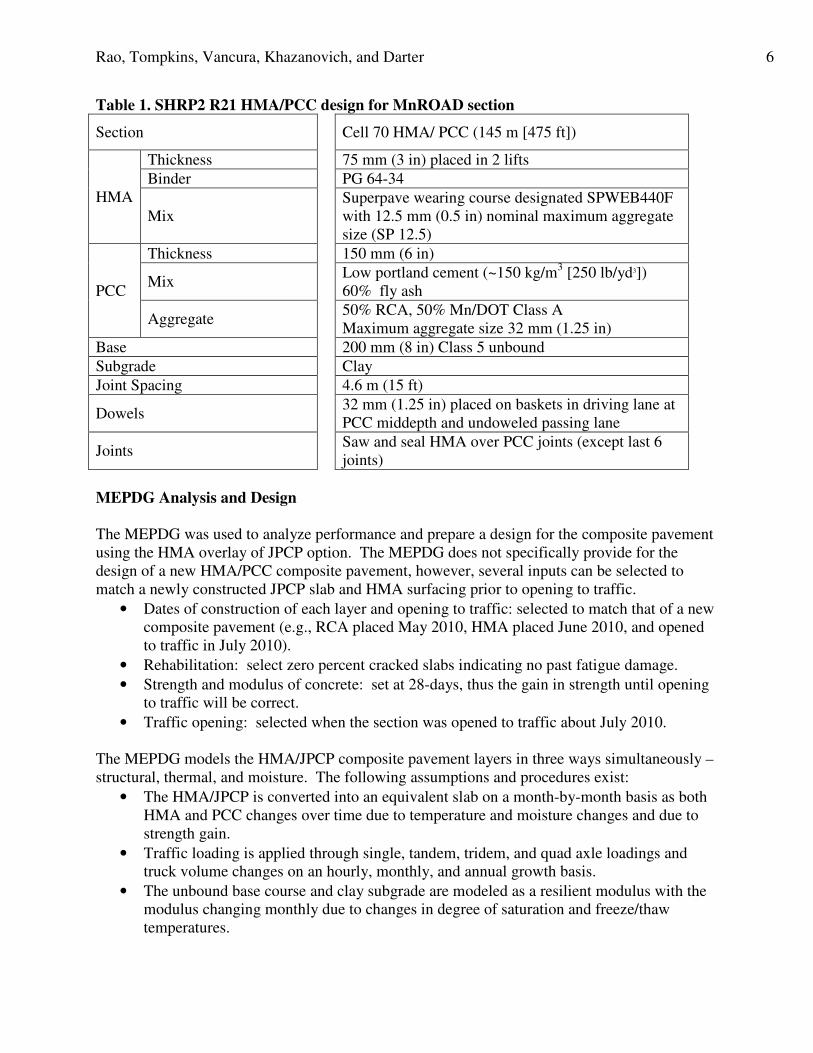
Table 1. SHRP2 R21 HMA/PCC design for MnROAD section
Section Cell 70 HMA/ PCC (145 m [475 ft])
HMA
Thickness 75 mm (3 in) placed in 2 lifts
Binder PG 64-34
Mix
Superpave wearing course designated SPWEB440F
with 12.5 mm (0.5 in) nominal maximum aggregate
size (SP 12.5)
PCC
Thickness 150 mm (6 in)
Mix Low portland cement (~150 kg/m
3 [250 lb/yd3])
60% fly ash
Aggregate 50% RCA, 50% Mn/DOT Class A
Maximum aggregate size 32 mm (1.25 in)
Base 200 mm (8 in) Class 5 unbound
Subgrade Clay
Joint Spacing 4.6 m (15 ft)
Dowels 32 mm (1.25 in) placed on baskets in driving lane at
PCC middepth and undoweled passing lane
Joints Saw and seal HMA over PCC joints (except last 6
joints)
MEPDG Analysis and Design
The MEPDG was used to analyze performance and prepare a design for the composite pavement
using the HMA overlay of JPCP option. The MEPDG does not specifically provide for the
design of a new HMA/PCC composite pavement, however, several inputs can be selected to
match a newly constructed JPCP slab and HMA surfacing prior to opening to traffic.
• Dates of construction of each layer and opening to traffic: selected to match that of a new
composite pavement (e.g., RCA placed May 2010, HMA placed June 2010, and opened
to traffic in July 2010).
• Rehabilitation: select zero percent cracked slabs indicating no past fatigue damage.
• Strength and modulus of concrete: set at 28-days, thus the gain in strength until opening
to traffic will be correct.
• Traffic opening: selected when the section was opened to traffic about July 2010.
The MEPDG models the HMA/JPCP composite pavement layers in three ways simultaneously –
structural, thermal, and moisture. The following assumptions and procedures exist:
• The HMA/JPCP is converted into an equivalent slab on a month-by-month basis as both
HMA and PCC changes over time due to temperature and moisture changes and due to
strength gain.
• Traffic loading is applied through single, tandem, tridem, and quad axle loadings and
truck volume changes on an hourly, monthly, and annual growth basis.
• The unbound base course and clay subgrade are modeled as a resilient modulus with the
modulus changing monthly due to changes in degree of saturation and freeze/thaw
temperatures.

Rao, Tompkins, Vancura, Khazanovich, and Darter 7
• Hourly temperatures are computed throughout the HMA and JPCP layers and converted
into temperature gradients for use in stress calculation. Moisture gradient through the
slab depends on the monthly relative humidity. Note that for new composite pavements
with HMA surfaces, this calculation is not quite correct and needs to be modified since
the top of the concrete will now be saturated much of the time.
• Distress types predicted include the following:
o Top-down and bottom-up fatigue concrete slab transverse cracking,
o Rutting of the HMA surfacing,
o Transverse reflection cracking of the HMA surfacing,
o Top down fatigue longitudinal cracking of the HMA surfacing in the wheel path,
o Bottom up fatigue cracking in the HMA surfacing, and
o IRI.
Table 2 shows the output from the MEPDG run over a 15 year period where the composite
pavement was loaded with over 8 million trucks (or over 16 million ESALs). The only two
distresses that are expected to show problems include the following:
• Reflection cracking from the transverse joints: Note that most of the transverse joints
were sawed and sealed which may mitigate their deterioration into a maintenance
requirement. Some joints were left unsealed and they should breakdown and deteriorate.
• Transverse (bottom-up) fatigue cracking from the slab. Obviously, this 75-mm (3-in)
HMA over 150-mm (6-in) jointed RCA PCC pavement is not sufficient to last more than
15 years and 8 million heavy truck loadings and a thicker slab would be needed if this
were regular Mn/DOT design over a 35-year period and not a research project. In fact,
by increasing the PCC thickness from 150 mm (6 in) to 200 mm (8 in), the composite
pavement design life would be extended to 30 years and 20 million trucks with no
fatigue cracking of the PCC slabs.
Table 2. Predicted performance of the MnROAD HMA/PCC pavement over time using the
MEPDG (note: inputs level 1 from construction data)
Age/
Trucks*
Transverse
Slab
Crack**
Transverse
Joint Reflection
Cracks
Rutting,
in
Top-Down
Longitudinal
Crack, %
Bottom Up
HMA
Fatigue
Cracking, %
IRI,
in/mi
0/0 0 0 0 0 0 63
5/2.5 1.1% All trans. joints 0.11 0 0 93
10/5 3.9% All trans. joints +
3.9% slabs 0.15 0 0 100
15/8 8.1% All trans. joints +
8% slabs 0.19 0 0 107
*Age in years/trucks in millions in design lane (multiply by 2 to obtain rigid ESALs)
**All bottom-up fatigue cracking.
Recycling Operations
The recycling operations consisted of breaking, removing, transporting, crushing, washing,
screening and stockpiling of the concrete pavement material from an existing MnROAD cell to
be used as coarse aggregate in the recycled concrete mix. The concrete portions of the existing

Rao, Tompkins, Vancura, Khazanovich, and Darter 8
cells were broken with a guillotine crusher, removed, and transported to a crushing location
(figure 1). At the crushing location this concrete material was crushed with an impact type
crusher operating at less than full capacity, then washed, screened and stockpiled. As specified,
all joint material, reinforcing members, and other inert material (such as wood) were separated
from the concrete sections before the existing concrete was crushed into coarse aggregate.
The crushing method and system determines some of the qualities of the RCA such as mortar
content and the gradation. An increase in the number of crushing processes reduces the mortar
content (Sanchez and Gutierrez 2009). For this project the contractor used an industrial crushing
operation that included a primary jaw crusher and a secondary cone crusher (figure 1). The jaw
crusher jaws were distanced to adjust the maximum aggregate size produced. The cone crusher
was used as secondary crusher to further remove the mortar from the natural aggregates. A cone
crusher squeezes material between an eccentrically gyrating spindle and a bowl below. As the
pieces are broken they fall to the lower, more closely spaced part of the crusher and further
crushed until small enough to fall through the bottom opening.
Figure 1. Salvage operations showing broken PCC pavement (top left) and removal (top
right). Jaw crusher (bottom left) and cone crusher (bottom right) used in the production of
RCA at MnROAD
Laboratory tests on the recycled aggregate (AASHTO T-84 and T-85) revealed that the RCA
percent absorption was 2.93%.
Rao, Tompkins, Vancura, Khazanovich, and Darter 9
PCC Mix Design
Per the special provisions, the RCA comprised 50% of the total coarse aggregate in the PCC mix.
Also, aggregate fines less than 4.75 mm (#4) and coarse aggregates greater than 25.4 mm (1”)
used in the PCC mix were specified to come from virgin aggregate sources. The special
provisions also required the contractor to clean and wash the RCA. Up to 10% of the total
recycled coarse aggregate could consist of bituminous particles as per the special provisions.
The cementitious fraction was specified to be comprised of up to 60% supplementary
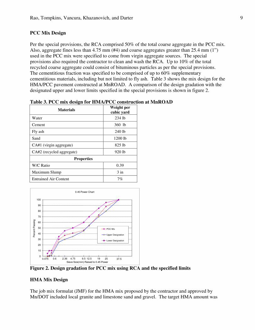
cementitious materials, including but not limited to fly ash. Table 3 shows the mix design for the
HMA/PCC pavement constructed at MnROAD. A comparison of the design gradation with the
designated upper and lower limits specified in the special provisions is shown in figure 2.
Table 3. PCC mix design for HMA/PCC construction at MnROAD
Materials Weight per
cubic yard
Water 234 lb
Cement 360 lb
Fly ash 240 lb
Sand 1200 lb
CA#1 (virgin aggregate) 825 lb
CA#2 (recycled aggregate) 920 lb
Properties
W/C Ratio 0.39
Maximum Slump 3 in
Entrained Air Content 7%
1912.59.54.752.36 37.50.6 250.075
0
1
0
10
20
30
40
50
60
70
80
90
100
0 . 0 4 . 0
Perc
ent P
assin
g
Sieve Size(mm) Raised to 0.45 Power
0.45 Power Chart
PCC Mix
Upper Designation
Lower Designation
Figure 2. Design gradation for PCC mix using RCA and the specified limits
HMA Mix Design
The job mix formulat (JMF) for the HMA mix proposed by the contractor and approved by
Mn/DOT included local granite and limestone sand and gravel. The target HMA amount was

Rao, Tompkins, Vancura, Khazanovich, and Darter 10
5.4% with 4.0% air voids. Tests indicated a gyratory density of 2,386 kg/m3 (149 lbs/ft
3) at 90
design gyrations. 100% of the aggregates pass the 19 mm (¾ in) sieve and 4.5% of the
aggregates passes the #200 sieve.
Paving Operations
The paving operations for the construction of HMA/PCC composite pavement at MnROAD are
summarized below and shown in figures 3 through 6:
1. Place lower PCC layer – The lower PCC layer was paved on May 5th
. The tie bars
and dowel bars (with the use of dowel baskets) were placed in the lower layer of the
concrete at the middepth (75 mm [3 in]) of the PCC layer. Dowels were only used in
the driving lane, while the passing lane was undoweled as per plans. As part of this
research the pavement layers were instrumented with embedded thermocouples,
moisture sensors, dynamic strain gauges, and vibrating wire strain gauges. The goal
of the instrumentation is to study the responses of the HMA/PCC composite
pavements to environmental and traffic loading, which will be used in developing
mechanistic-empirical procedures for the design of HMA/PCC composite pavements.
2. Finish smooth – The surface was finished smooth to remove surface irregularities.
3. Texture surface (longitudinal tined) – The surface of the PCC layer was
longitudinally tined to texture the surface and ensure a mechanical bond between the
PCC and HMA layer. Texturing the surface of the concrete has been shown in
previous studies (Al-Qadi 2008, Leng 2008) to improve bond strength.
4. Spray on a curing compound – The surface of the PCC layer was sprayed with a
curing compound to control the surface drying of the PCC and minimize early-age
distresses. The PCC was specified to be cured for 7 days or until the flexural strength
of the concrete samples reach 550 psi, before the HMA overlay was to be placed.
There was some concern that the curing compound would reduce the bond between
the HMA and PCC. Bonding will be examined over time through coring and NDT
testing.
5. Saw concrete joints – Unsealed single saw cuts for both transverse and longitudinal
joints were cut in the PCC as soon as it gained adequate strength to perform the saw
cutting operation without spalling the PCC. Both transverse and longitudinal joints
were cut at depth of T/3 where T indicates the thickness of the PCC (50 mm [2 in] for
the 150-mm [6-in] PCC).
6. Pave HMA surface – The HMA surface was specified to be paved after 7 days or a
concrete flexural strength of 550 psi. The paving of the HMA layer was performed
on May 20th
, 15 days following the construction of the PCC layer at the discretion of
the paving contractor due to weather-related delays. A bituminous tack coat was
sprayed on the concrete before the HMA paving to further help ensure adequate long
term bonding between the PCC and the HMA. Applying a tack coat to the PCC
surface has been shown in previous laboratory and field studies (Donovan et al. 2000,
Al-Qadi 2008, Leng et al. 2008) to improve bond strength.
7. Saw and seal HMA over the PCC transverse joints – Bituminous transverse joints
were cut with a single saw cut of 12.5 mm (0.5 in) wide by 16 mm (5/8 in) deep for
the HMA layer. The sawn bituminous joints were specified to be located within 12.5

Rao, Tompkins, Vancura, Khazanovich, and Darter 11
mm (0.5 in) of the concrete joints. The contractor ensured this by using stakes
beyond the aggregate shoulders to mark the location of the joints in the PCC. 6 joints
were left unsealed for research purposes.
Figure 3. Placement of the RCA PCC layer
Figure 4. Instrumentation installed prior to placement of the PCC to measure pavement
responses to temperature and traffic loads (dynamic strain gages – top left, static strain
gages – bottom left, humidity sensors – bottom right, overall view – top right)

Rao, Tompkins, Vancura, Khazanovich, and Darter 12
Figure 5. Texturing and curing of the RCA PCC
Figure 6. Tack coat applied to PCC surface (top left) prior to HMA paving (top right).
Sawing (bottom left) and sealing (bottom right) HMA layer – saw cuts in the HMA were
matched to the saw cuts in the PCC below to within 12.5 mm (0.5 in)
As-Constructed Properties
The Federal Highway Administration (FHWA) Mobile Concrete Lab visited the R21
construction site and collected PCC cores and material samples. The results, which are the
average of two tests, are summarized in table 4. As constructed material properties for the HMA
mix is shown in table 5.
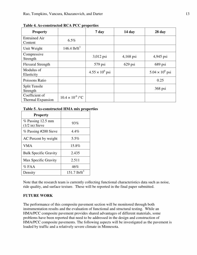
Rao, Tompkins, Vancura, Khazanovich, and Darter 13
Table 4. As-constructed RCA PCC properties
Property 7 day 14 day 28 day
Entrained Air
Content 6.5%
Unit Weight 146.4 lb/ft3
Compressive
Strength 3,012 psi 4,168 psi 4,945 psi
Flexural Strength 579 psi 629 psi 689 psi
Modulus of
Elasticity 4.55 × 10
6 psi 5.04 × 10
6 psi
Poissons Ratio 0.25
Split Tensile
Strength 368 psi
Coefficient of
Thermal Expansion 10.4 × 10
-6 /°C
Table 5. As-constructed HMA mix properties
Property
% Passing 12.5 mm
(1/2 in) Sieve 93%
% Passing #200 Sieve 4.4%
AC Percent by weight 5.5%
VMA 15.8%
Bulk Specific Gravity 2.435
Max Specific Gravity 2.511
% FAA 46%
Density 151.7 lb/ft3
Note that the research team is currently collecting functional characteristics data such as noise,
ride quality, and surface texture. These will be reported in the final paper submitted.
FUTURE WORK
The performance of this composite pavement section will be monitored through both
instrumentation results and the evaluation of functional and structural testing. While an
HMA/PCC composite pavement provides shared advantages of different materials, some
problems have been reported that need to be addressed in the design and construction of
HMA/PCC composite pavements. The following aspects will be investigated as the pavement is
loaded by traffic and a relatively severe climate in Minnesota.

Rao, Tompkins, Vancura, Khazanovich, and Darter 14
1. Comparison of the overall performance with other sections at MnROAD: There are
several other sections, including especially the SHRP 2 PCC/PCC wet-on-wet sections,
will be compared to the performance of this HMA/PCC section. The diversion of traffic
from the MnROAD test sections to the parallel roadway, to conduct in-depth studies will
be invaluable over time.
2. Instrumentation, structural, and performance monitoring data: Extensive temperature,
moisture, deflection, and strain data is being collected and will be analyzed to determine
the basic mechanistic behavior of the composite pavement. Monitoring will include
FWD testing, other NDT, coring, smoothness, all forms of cracking, rutting, texture,
noise and other factors. These results will provide a comprehensive knowledge of the
mechanisms behind the composite pavements performance.
3. Impact of placement of the RCA PCC layer: The 6-in layer that included very high
amount of fly ash was quite sensitive to water content, and this caused some problems
with consistent placement. Some visual “tearing’ of the plastic concrete surface (for
dryer mixes) was observed. The effects of this on performance will be investigated
through NDT, backcalculation, and cores. The strength and modulus of the lab tested
RCA was excellent with a typical coefficient of thermal expansion.
4. Fatigue cracking of the RCA PCC layer: This layer was 150 mm (6 in) thick so that
fatigue cracking would initiate within a few years of heavy traffic. A normal concrete
pavement carrying heavy Interstate 94 traffic would be several inches thicker especially if
it were designed to limit fatigue damage over a long service life. The HMA surface is
expected to reduce the required thickness due to the reduction in thermal and moisture
gradients through the RCA PCC slab. Thermal and moisture gradients in the HMA/PCC
will be measured and compared to PCC/PCC sections.
5. Reflective cracking: Reflective cracking is the most common problem reported in the
literature for composite pavements. Various reflective cracking treatments have been
used but without consistent success. The jointing or cracking of the base PCC slab is one
factor that is critical to reflective cracking, with shorter spaced joints and cracks
considered superior. The load transfer efficiency of these joints and cracks over time is
also critical. Reflective cracking for the HMA/PCC pavement at MnROAD was
addressed by sawing and sealing a majority of joints in the HMA layer and use of dowel
bars in the driving lane to maintain high load transfer of transverse joints. As discussed
before, 6 joints were not sawed and sealed and the passing lane was undoweled. The
condition of all these joints and the bonding nearby will be monitored and evaluated.
6. Inadequate bond or loss of bond between the HMA wearing surface and lower PCC layer:
Another problem that has been reported on HMA/PCC composite pavements is the lack
of interface friction or bond between the HMA surface and lower PCC layer. Inadequate
bond will result in fatigue cracking, potholes, and slippage cracks (NAPA 2000).
Adequate bond was attempted at the MnROAD construction through a combination of
mechanical texturing of the PCC surface and placement of a tack coat. Bond will be
investigated over time through coring and NDT.
7. Cost analysis: A complete cost analysis of the construction costs and future maintenance
and rehabilitation costs will be conducted for this composite pavement. Although two
paving operations (concrete and asphalt) are required, the lower cost of the RCA in most
instances where quality aggregate shortages exist) should show the pavement to be
Rao, Tompkins, Vancura, Khazanovich, and Darter 15
competitive. Many areas of the United States are now shipping high quality aggregates
for hundreds of miles to a project. There are many existing old PCC pavements that can
be recycled into a lower layer of RCA and resurfaced with a high quality thin HMA-type
surface. Aggregate durability is less of a concern compared to conventional JPCP
because of the high quality surface layer. Note also that because the PCC layer is not the
surface riding layer, the contractor does not need to perform spot grinding of the PCC
layer to meet the smoothness specifications or incentives. The lower PCC layer can be
constructed quicker than a conventional PCC pavement, because the lower layer need not
be constructed to the same degree of smoothness.
CONCLUSIONS
Thin asphalt surfacing over jointed plain or continuously reinforced PCC layers are a promising
technology and represent another design option for pavement engineers. These pavements are
designed to have the structural capacity and long life of PCC pavements (can be designed for
minimal cracking over design life) with the functional characteristics (smoothness, friction, and
low noise) of asphalt-surfaced pavements. There are several different types of HMA surfaces
that have been used including porous HMA, rubber-asphalt porous friction course, SMA, and
Novachip among others. By design, the surface HMA layer is expected to be milled and
replaced when the functional characteristics drop below an acceptable level. This renewal can be
done rapidly with minimal disruption to the traveling public.
The construction at MnROAD of an HMA/PCC composite pavement with recycled coarse
aggregates in the PCC layer demonstrated the ability to construct a more sustainable HMA/PCC
composite pavement (the old PCC pavement was broken up, hauled to a crusher and recycled
into coarse aggregate for the lower layer). However, there are still many issues that need to be
resolved including the performance of saw and sealed joints, the long term bonding between the
HMA and PCC, the possible development of joint faulting, durability of the RCA, and the
reduction of fatigue cracking of the relatively thin PCC slab with an HMA surface that should
reduce the extreme temperature gradients.
ACKNOWLEDGEMENTS
The authors acknowledge the support of the Strategic Highway Research Program Project R21.
Dr. James Bryant is the SHRP2 R21 Project Manager. The authors would like to thank Prof.
Julie Vandenbossche of the University of Pittsburgh and graduate students at both the
Universities of Minnesota and Pittsburgh for their assistance. Also, the authors thank the
Minnesota Department of Transportation (Mn/DOT) and Mr. Mark Watson, who served as the
Mn/DOT project manager, McCrossan Inc., the general construction contractor for the project,
and the FHWA for providing the services of the Mobile Concrete Lab.

Rao, Tompkins, Vancura, Khazanovich, and Darter 16
REFERENCES
Al-Qadi, I. L. et al. Tack Coat Optimization for HMA Overlays: Laboratory Testing. Report
Number FHWA-ICT-08-023. Illinois Center for Transportation, University of Illinois.
September 2008.
Baker, R.F. 1973. “New Jersey Composite Pavement Project,” Highway Research Record,
Number 434, pp. 16-23.
Darter, M.I. and E.J. Barenberg. 1976. Zero-Maintenance Pavement: Field Studies on the
Performance Requirements and Capabilities of Conventional Pavement Systems, Report FHWA-
RD-76-105, FHWA.
Donovan, E. P., Al-Qadi, I. L., and Loulizi A. 2000. “Optimization of Tack Coat Application
Rate for Geocomposite Membrane on Bridge Decks.” Transportation Research Record: Journal
of the Transportation Research Board, Number 1740, p.143–50.
Leng, Z., Al-Qadi, I.L., Carpenter, S. H., and Ozer, H. 2008. “Interface Bonding between HMA
and Various PCC Surfaces: Laboratory Assessment.” Transportation Research Record: Journal
of the Transportation Research Board, Number 2127, p.20–28.
NAPA. 2000. Hot-Mix Asphalt Construction Reference for Quality HMA Pavements. QIP112.
National Asphalt Pavement Association.
Ryell, J., and Corkill, J.T. 1973. “Long-Term Performance of an Experimental Composite
Pavement”, Highway Research Record, Number 434, pp. 1-15.
Sanchez de Juan, M. and Gutierrez, P. A. 2009. “Study on the Influence of Attached Mortar
Content on the Properties of Recycled Concrete Aggregate,” Construction and Building
Materials, Volume 23, Issue 2, pp. 872-877.
Smith, P. 1963. “Past Performance of Composite Pavements”, Highway Research Record
Number 37, pp. 14-30.
Van Breemen, W. 1963. “Discussion of Possible Designs of Composite Pavements”, Highway
Research Record, Number 37, pp. 5- 10.
Von Quintus, H., F. Finn, R. Hudson, and F. Roberts. 1980. Flexible and Composite Structures
for Premium Pavements. FHWA RD-80-154 and 155, Federal Highway Administration,
Washington, D.C.


![POROUS ASPHALT PAVEMENTS1].pdf · Porous asphalt is an environmentally . friendly tool for stormwater management. POROUS. ASPHALT PAVEMENTS. In the natural environment, rainfall sinks](https://img.dokumen.tips/doc/110x75/5e0b552e1e73a745da693b59/porous-asphalt-pavements-1pdf-porous-asphalt-is-an-environmentally-friendly.jpg)


![POROUS ASPHALT PAVEMENTS1].pdf · Porous asphalt is an environmentally friendly tool for stormwater management. POROUS ASPHALT PAVEMENTS In the natural environment, rainfall sinks](https://img.dokumen.tips/doc/110x75/5afff62e7f8b9a54578be0b6/porous-asphalt-1pdfporous-asphalt-is-an-environmentally-friendly-tool-for-stormwater.jpg)