Embed Size (px)
Citation preview
Mechatronics LabMechatronics Lab
Design and characterization for regenerative shock absorbers
Candidate: Yijun XU
PhD in Mechanical Engineering Tutor: Prof. Nicola AMATI
Mechatronics Lab
Outlines
2
• Motivation and State of the Art
• Suspension assessment
• Design method for motor-pump unit
• Prototype assembly and efficiency assessment
• Experimental tests and results
• Conclusion and work in progress
Mechatronics Lab
Motivation and State of the art
3
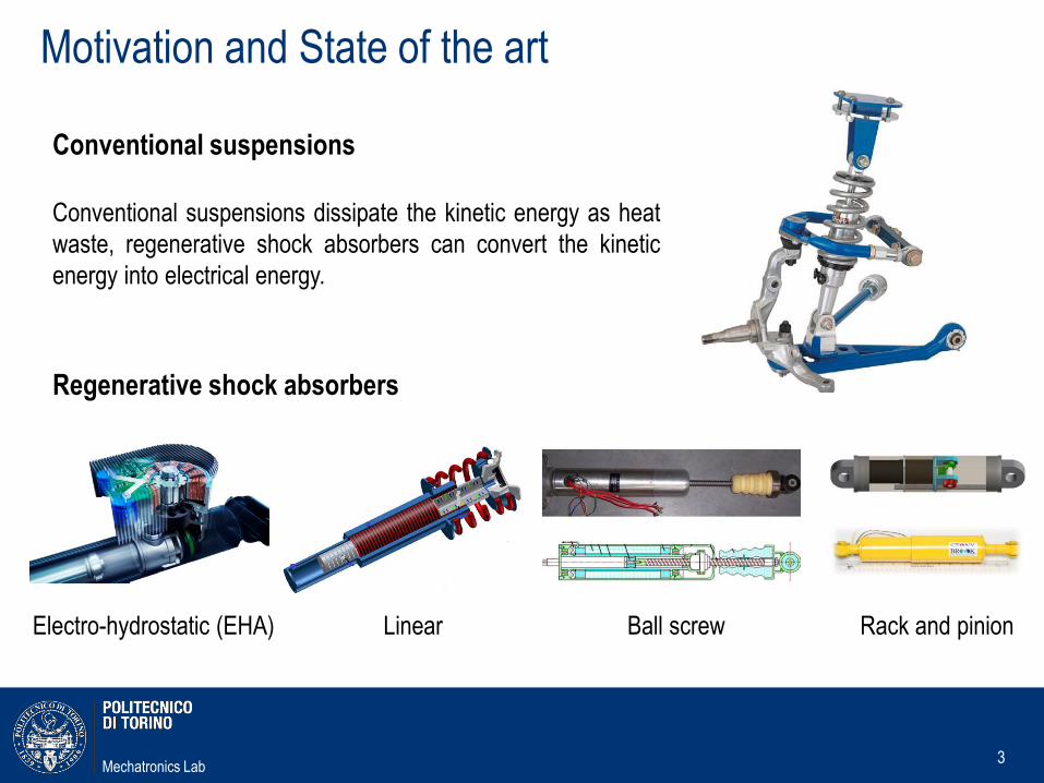
Regenerative shock absorbers
Conventional suspensions
Conventional suspensions dissipate the kinetic energy as heat
waste, regenerative shock absorbers can convert the kinetic
energy into electrical energy.
Linear Ball screw Rack and pinion Electro-hydrostatic (EHA)
Mechatronics Lab
Why EHA dampers?
4
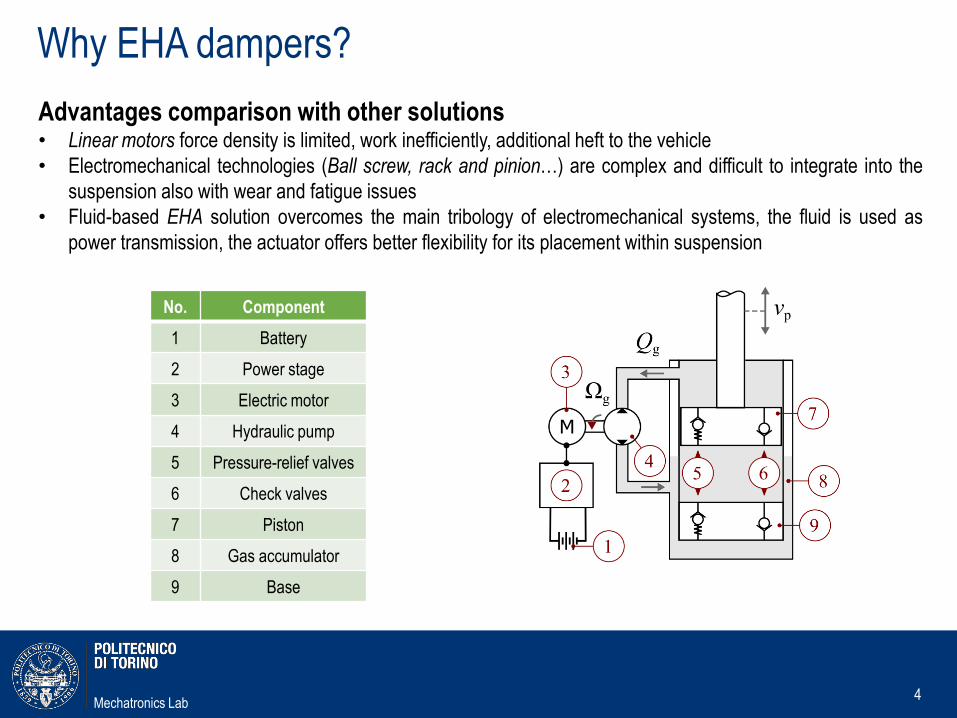
Advantages comparison with other solutions• Linear motors force density is limited, work inefficiently, additional heft to the vehicle
• Electromechanical technologies (Ball screw, rack and pinion…) are complex and difficult to integrate into the
suspension also with wear and fatigue issues
• Fluid-based EHA solution overcomes the main tribology of electromechanical systems, the fluid is used as
power transmission, the actuator offers better flexibility for its placement within suspension
No. Component
1 Battery
2 Power stage
3 Electric motor
4 Hydraulic pump
5 Pressure-relief valves
6 Check valves
7 Piston
8 Gas accumulator
9 Base
Mechatronics Lab
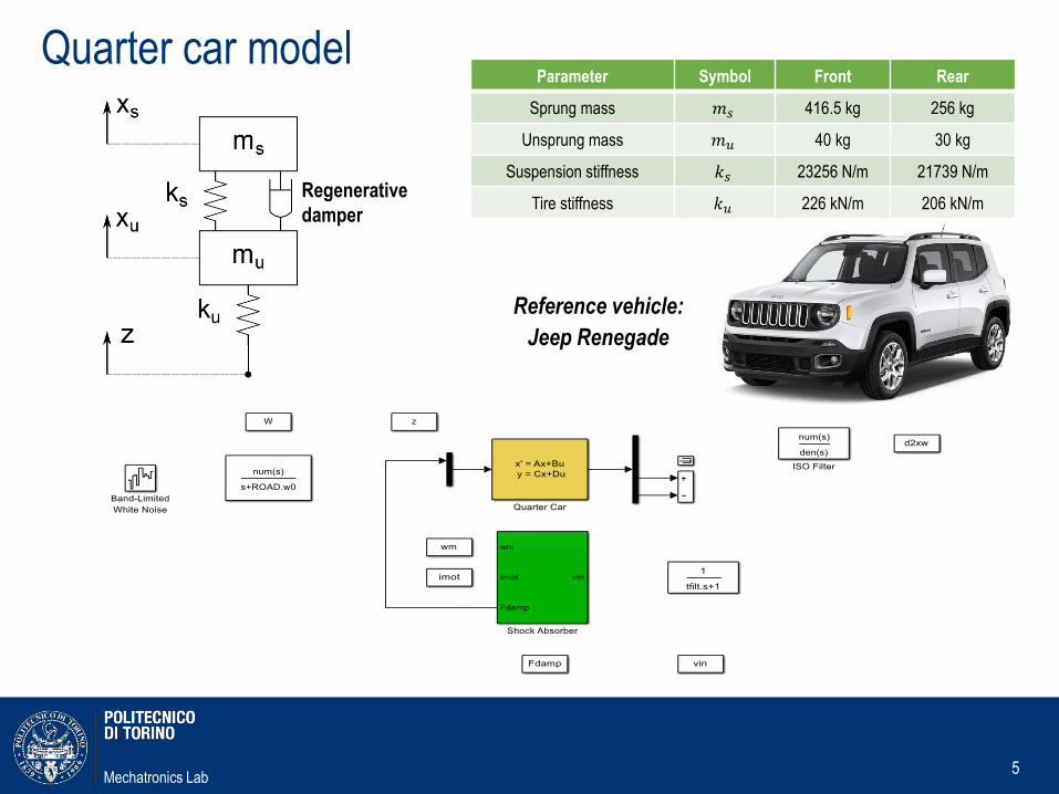
Quarter car model
5
Regenerative
damper
Reference vehicle:
Jeep Renegade
Parameter Symbol Front Rear
Sprung mass 𝑚𝑠 416.5 kg 256 kg
Unsprung mass 𝑚𝑢 40 kg 30 kg
Suspension stiffness 𝑘𝑠 23256 N/m 21739 N/m
Tire stiffness 𝑘𝑢 226 kN/m 206 kN/m
Mechatronics Lab
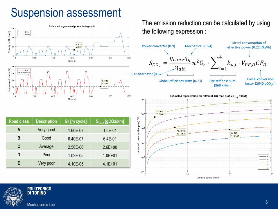
Suspension assessment
6
Road class Description Gr [m cycle] SCO2 [gCO2/km]
A Very good 1.60E-07 1.6E-01
B Good 6.40E-07 6.4E-01
C Average 2.56E-06 2.6E+00
D Poor 1.02E-05 1.0E+01
E Very poor 4.10E-05 4.1E+01
The emission reduction can be calculated by using
the following expression :
Mechatronics Lab
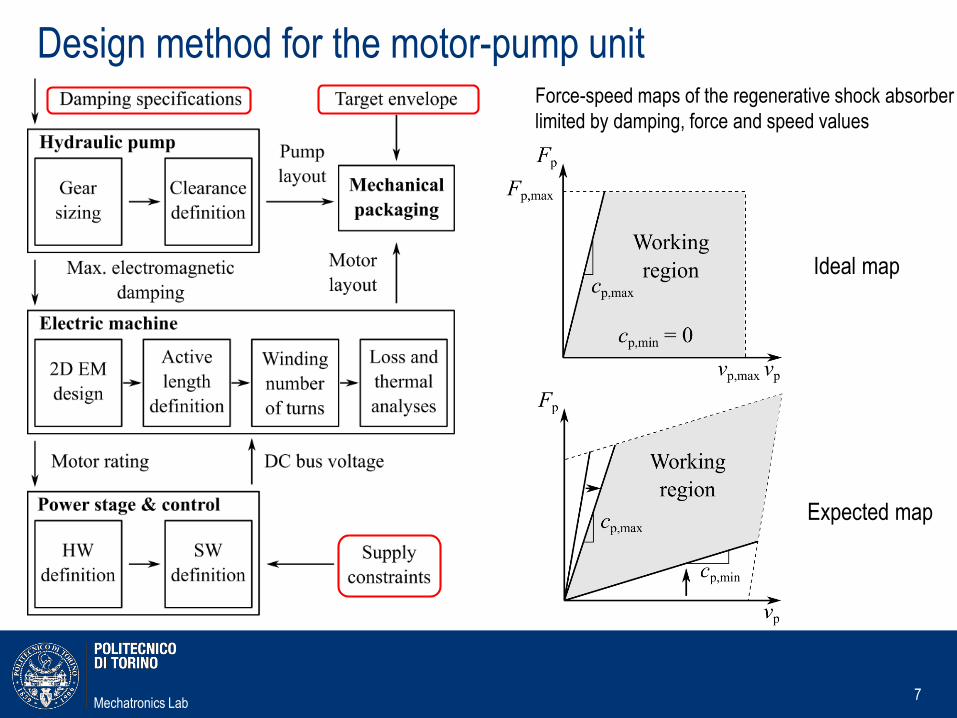
Design method for the motor-pump unit
7
Force-speed maps of the regenerative shock absorber
limited by damping, force and speed values
Ideal map
Expected map
Mechatronics Lab
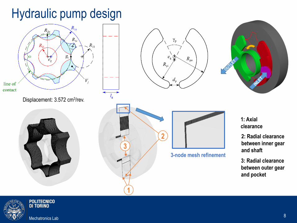
Hydraulic pump design
8
2
3
1
3-node mesh refinement
1: Axial
clearance
2: Radial clearance
between inner gear
and shaft
3: Radial clearance
between outer gear
and pocket
Displacement: 3.572 cm3/rev.
Mechatronics Lab
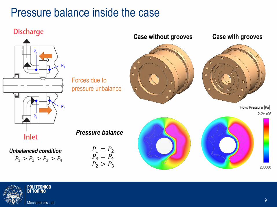
Pressure balance inside the case
9
P1
P4
P2
P3
Pressure balance
𝑃1 = 𝑃2𝑃3 = 𝑃4𝑃2 > 𝑃3
Unbalanced condition
𝑃1 > 𝑃2 > 𝑃3 > 𝑃4
Forces due to
pressure unbalance
Case with groovesCase without grooves
Mechatronics Lab
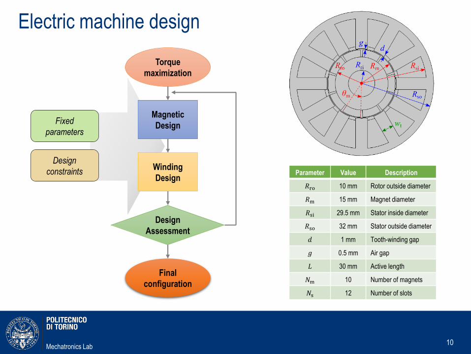
Electric machine design
10
Magnetic
Design
Torque
maximization
Winding
Design
Fixed
parameters
Design
constraints
Design
Assessment
Final
configuration
Parameter Value Description
𝑅ro 10 mm Rotor outside diameter
𝑅m 15 mm Magnet diameter
𝑅si 29.5 mm Stator inside diameter
𝑅so 32 mm Stator outside diameter
𝑑 1 mm Tooth-winding gap
𝑔 0.5 mm Air gap
𝐿 30 mm Active length
𝑁m 10 Number of magnets
𝑁s 12 Number of slots
Mechatronics Lab
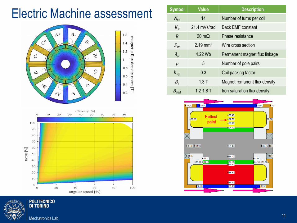
Electric Machine assessment
11
Hottest
point
Symbol Value Description
𝑁tc 14 Number of turns per coil
𝐾e 21.4 mVs/rad Back EMF constant
𝑅 20 mΩ Phase resistance
𝑆w 2.19 mm2 Wire cross section
𝜆𝑝 4.22 Wb Permanent magnet flux linkage
𝑝 5 Number of pole pairs
𝑘cp 0.3 Coil packing factor
𝐵r 1.3 T Magnet remanent flux density
𝐵sat 1.2-1.8 T Iron saturation flux density
Mechatronics Lab
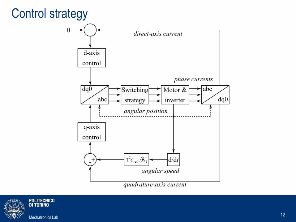
Control strategy
12
Mechatronics Lab
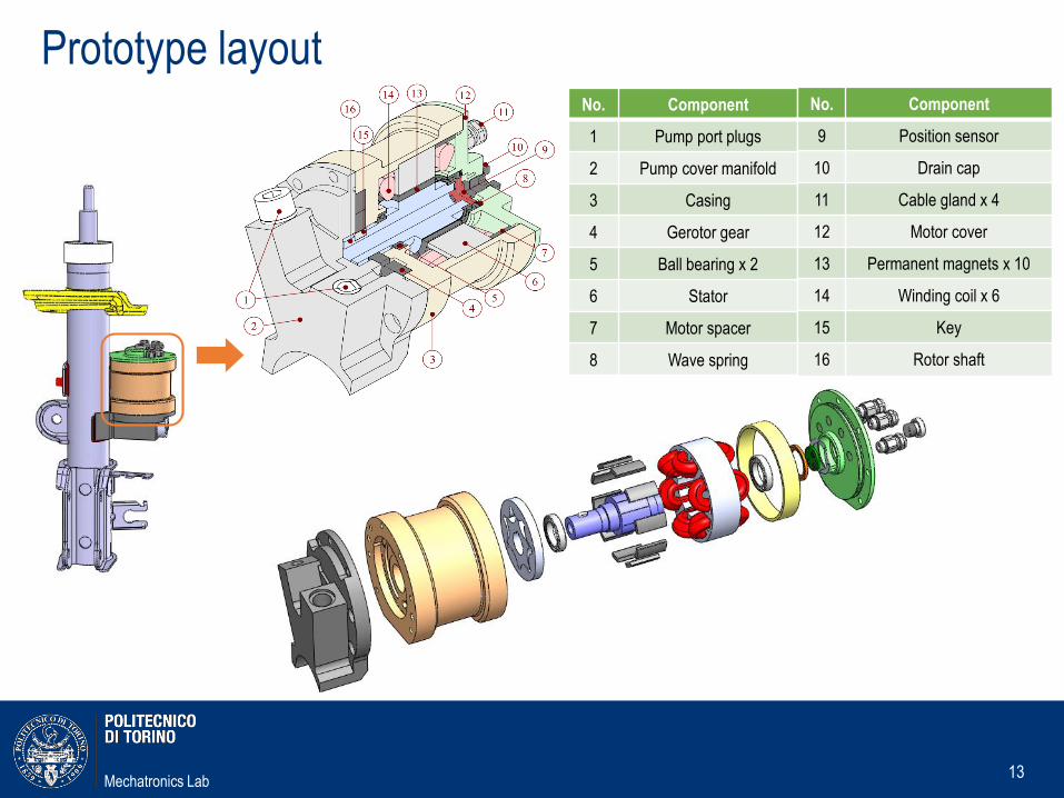
Prototype layout
13
No. Component
1 Pump port plugs
2 Pump cover manifold
3 Casing
4 Gerotor gear
5 Ball bearing x 2
6 Stator
7 Motor spacer
8 Wave spring
No. Component
9 Position sensor
10 Drain cap
11 Cable gland x 4
12 Motor cover
13 Permanent magnets x 10
14 Winding coil x 6
15 Key
16 Rotor shaft

Mechatronics Lab
Prototype layout
14
Main data Unit Value
Added mass per corner kg 2.1
Max diameter mm 88
Max axial size mm 84
Pump displacement cc/rev 3.57
Max e-motor torque Nm 0.67
Mechatronics Lab
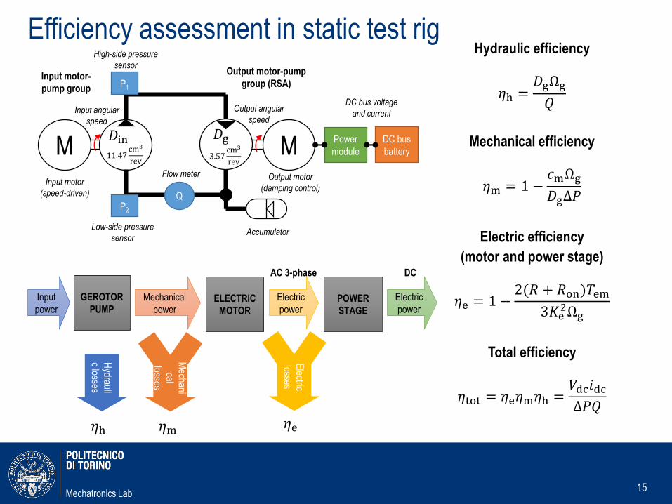
Efficiency assessment in static test rig
15
Input
power
GEROTOR
PUMP
Hydrauli
c losses
Mechanical
powerELECTRIC
MOTOR
Electric
powerPOWER
STAGE
Electric
power
AC 3-phase DC
Mechani
cal
losses
𝜂h 𝜂m 𝜂e
Electric
losses
𝐷in11.47
cm3
rev
𝐷g3.57
cm3
revM M
Q
P1
P2
Power
module
DC bus
battery
High-side pressure
sensor
Flow meter
Low-side pressure
sensor
Input angular
speed
Output angular
speed
DC bus voltage
and current
Input motor-
pump group
Output motor-pump
group (RSA)
Input motor
(speed-driven)
Output motor
(damping control)
Accumulator
Hydraulic efficiency
𝜂h =𝐷gΩg
𝑄
Mechanical efficiency
𝜂m = 1 −𝑐mΩg
𝐷gΔ𝑃
Electric efficiency
(motor and power stage)
𝜂e = 1 −2(𝑅 + 𝑅on)𝑇em
3𝐾e2Ωg
Total efficiency
𝜂tot = 𝜂e𝜂m𝜂h =𝑉dc𝑖dcΔ𝑃𝑄

Mechatronics Lab
Static test results
16
No. Description
1 Motor-pump prototype
2 Power stage
3 Driving motor-pump unit
4 Current probe
5 Hydraulic lines
6 Hand pump to fill the circuit
No. Description
7 Battery array
8 Data logging PC
9 Driving motor switchboard
10 Control PC
11 Gas-loaded accumulator
Mechatronics Lab
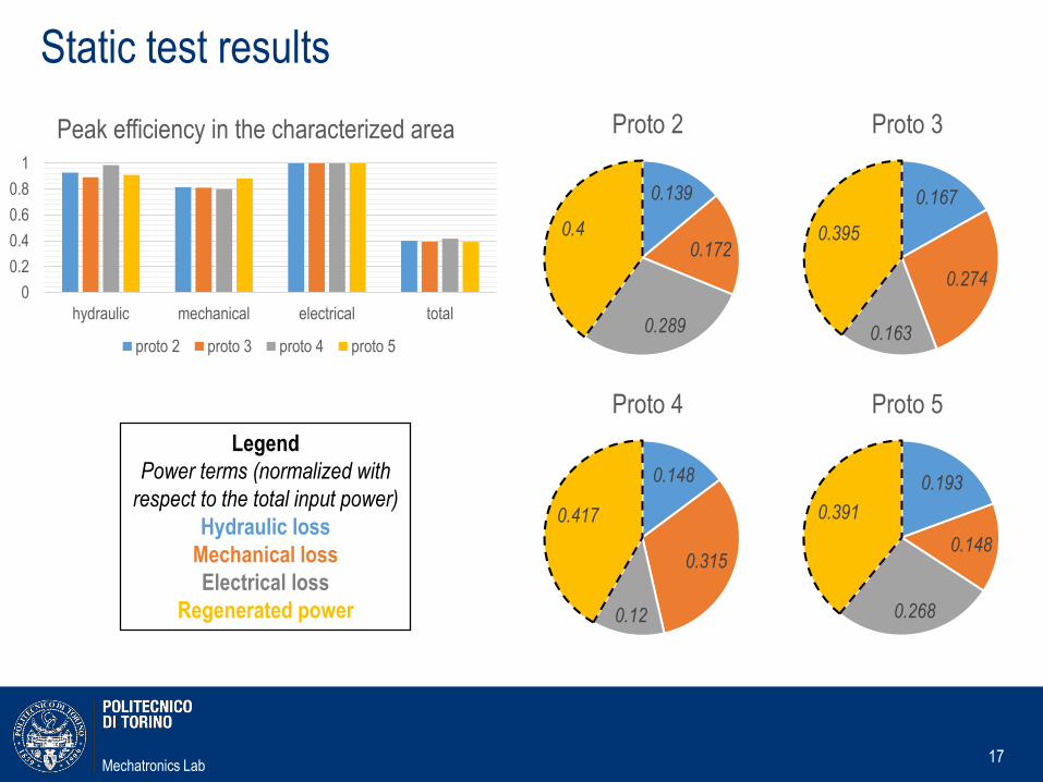
Static test results
17
0.139
0.172
0.289
0.4
Proto 2
0.167
0.274
0.163
0.395
Proto 3
0.148
0.315
0.12
0.417
Proto 4
0.193
0.148
0.268
0.391
Proto 5
Legend
Power terms (normalized with
respect to the total input power)
Hydraulic loss
Mechanical loss
Electrical loss
Regenerated power
0
0.2
0.4
0.6
0.8
1
hydraulic mechanical electrical total
Peak efficiency in the characterized area
proto 2 proto 3 proto 4 proto 5
Mechatronics Lab
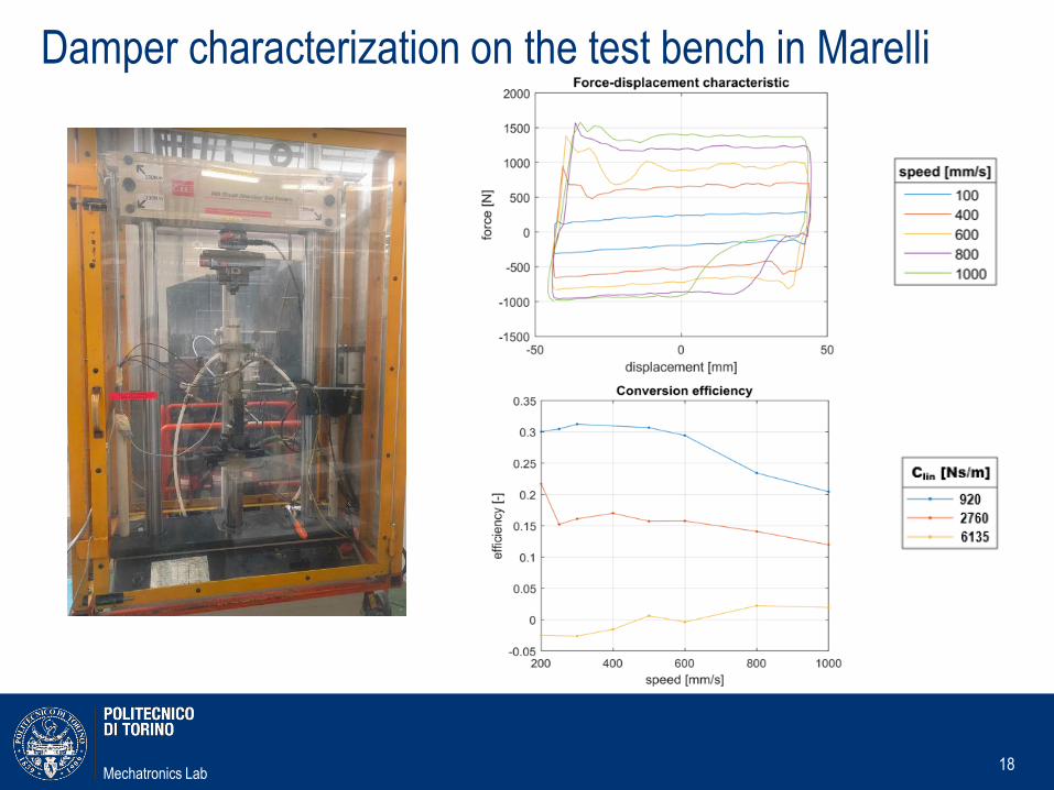
Damper characterization on the test bench in Marelli
18
Mechatronics Lab
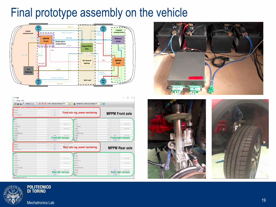
Final prototype assembly on the vehicle
19
Front axle reg. power monitoring
Rear axle reg. power monitoring
Front-left damper Front-right damper
Rear-left damper Rear-right damper
MPPM Front axle
MPPM Rear axle
Mechatronics Lab
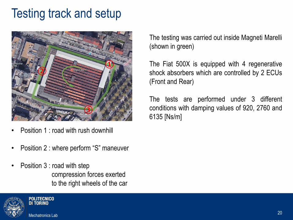
Testing track and setup
20
The testing was carried out inside Magneti Marelli
(shown in green)
The Fiat 500X is equipped with 4 regenerative
shock absorbers which are controlled by 2 ECUs
(Front and Rear)
The tests are performed under 3 different
conditions with damping values of 920, 2760 and
6135 [Ns/m]
• Position 1 : road with rush downhill
• Position 2 : where perform “S” maneuver
• Position 3 : road with step
compression forces exerted
to the right wheels of the car
①②
③
Mechatronics Lab
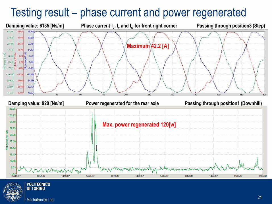
Testing result – phase current and power regenerated
21
Damping value: 6135 [Ns/m] Phase current Iu, Iv and Iw for front right corner Passing through position3 (Step)
Maximum 42.2 [A]
Max. power regenerated 120[w]
Damping value: 920 [Ns/m] Power regenerated for the rear axle Passing through position1 (Downhill)
Mechatronics Lab
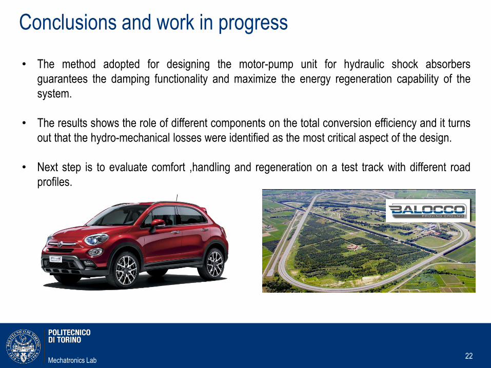
Conclusions and work in progress
22
• The method adopted for designing the motor-pump unit for hydraulic shock absorbers
guarantees the damping functionality and maximize the energy regeneration capability of the
system.
• The results shows the role of different components on the total conversion efficiency and it turns
out that the hydro-mechanical losses were identified as the most critical aspect of the design.
• Next step is to evaluate comfort ,handling and regeneration on a test track with different road
profiles.
Mechatronics Lab23
The End
Thank You for Your Attention