Embed Size (px)
Citation preview
DESIGN AND ANALYSIS OF LEAF SPRINGS USING COMPOSITE
MATERIAL FOR LMV
M.Vimal Teja1, V.Sai Surendra2, B.Sudhakara Rao3, K.Radha Krishna4,
Y.Venkatesh5
1,2,3,4,5 Dept. of Mechanical Engineering, Ramachandra College of Engineering, Eluru, AP. [email protected]
2 [email protected] [email protected] [email protected] [email protected]
ABSTRACT: The automobile vehicles have number of parts which can be able to replace by composite material, but due to
the improvement of mechanical properties of composite material. It has more elastic strength and high strength to weight ratio
has compared with those of steel material. So, out of many components one of the components of automobile, the leaf spring
which use for carried out the whole weight of the vehicle is best option for replacement of steel material by composite material.
For reduce the weight of leaf spring the analysis was carried out on the Light duty Vehicle Mahindra Model Bolero Maxi Truck
leaf springs with same dimensional geometry. The material select for leaf spring are Graphite epoxy composite material which
is more economical with similar mechanical and geometrical properties to the steel leaf spring. The aim of this report was to
design and analysis of Leaf springs. It is modeled by using Auto CAD, and Static analysis is done on the Leaf springs by using
ANSYS 16.0 software. Deflections, stresses values are calculated.
KEYWORDS: Leaf Springs, Graphite Epoxy, ANSYS 16.0, Auto CAD.
1. INTRODUCTION
In now a day the fuel efficiency and emission gas regulation of automobiles are two important issues. To fulfil this
problem the automobile industries are trying to make new vehicle which can provide high efficiency with low cost.
The best way to increase the fuel efficiency is to reduce the weight of the automobile. The weight reduction can be
achieved primarily by the introduction of better material, design optimization and better manufacturing processes.
The achievement of weight reduction with adequate improvement of mechanical properties has made composite a
very good replacement material for conventional steel. In automobile car out of many components one of the
components of automobile which can be easily replaced is leaf spring. A leaf spring is a simple form of spring,
commonly used for the suspension in wheeled vehicles. The suspension of leaf spring is the area which needs to
focus to improve the suspensions of the vehicle for comfort ride. The suspension leaf spring is one of the potential
items for weight reduction in automobile as it accounts for 10 to 20% of unspring weight.
It is well known that springs are designed to absorb shocks. So the strain energy of the material becomes a major
factor in designing the springs. The introduction of composite material will make it possible to reduce the weight of
the leaf spring without reduction in load carrying capacity and stiffness. Since the composite material have high
strength to weight ratio and have more elastic strain energy storage capacity as compared with steel. It can be easily
observed that material having lower density and modulus will have a greater specific strain energy capacity. Thus
composite material offer high strength and light weight. In this work, leaf springs of automobile vehicle are
Mahindra Model Maxi Truck is considers for further investigation. The suspension quality can be improved by
minimizing the vertical vibrations, impacts and bumps due to road irregularities which create the comfortable ride.
1.2 CONSTRUCTION OF LEAF SPRING
A leaf spring commonly used in automobiles is of semi-elliptical form as shown in Figure 1.1. It is built up of a
number of plates (known as leaves). The leaves are usually given an initial curvature or cambered so that they will
tend to straighten under the load. The leaves are held together by means of a band shrunk around them at the centre
or by a bolt passing through the centre. Since the band exerts stiffening and strengthening effect, therefore the
International Journal of Scientific Research and Review
Volume 7, Issue 2, 2018
ISSN NO: 2279-543X
http://dynamicpublisher.org/103
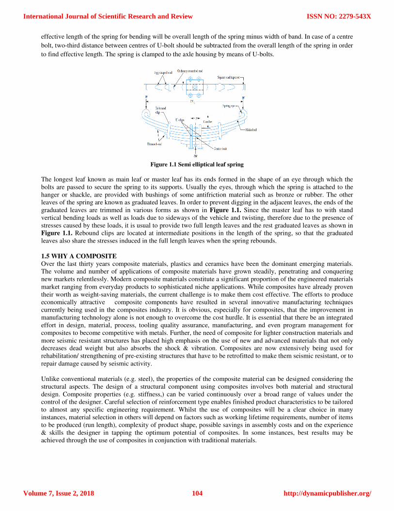
effective length of the spring for bending will be overall length of the spring minus width of band. In case of a centre
bolt, two-third distance between centres of U-bolt should be subtracted from the overall length of the spring in order
to find effective length. The spring is clamped to the axle housing by means of U-bolts.
Figure 1.1 Semi elliptical leaf spring
The longest leaf known as main leaf or master leaf has its ends formed in the shape of an eye through which the
bolts are passed to secure the spring to its supports. Usually the eyes, through which the spring is attached to the
hanger or shackle, are provided with bushings of some antifriction material such as bronze or rubber. The other
leaves of the spring are known as graduated leaves. In order to prevent digging in the adjacent leaves, the ends of the
graduated leaves are trimmed in various forms as shown in Figure 1.1. Since the master leaf has to with stand
vertical bending loads as well as loads due to sideways of the vehicle and twisting, therefore due to the presence of
stresses caused by these loads, it is usual to provide two full length leaves and the rest graduated leaves as shown in
Figure 1.1. Rebound clips are located at intermediate positions in the length of the spring, so that the graduated
leaves also share the stresses induced in the full length leaves when the spring rebounds.
1.5 WHY A COMPOSITE
Over the last thirty years composite materials, plastics and ceramics have been the dominant emerging materials.
The volume and number of applications of composite materials have grown steadily, penetrating and conquering
new markets relentlessly. Modern composite materials constitute a significant proportion of the engineered materials
market ranging from everyday products to sophisticated niche applications. While composites have already proven
their worth as weight-saving materials, the current challenge is to make them cost effective. The efforts to produce
economically attractive composite components have resulted in several innovative manufacturing techniques
currently being used in the composites industry. It is obvious, especially for composites, that the improvement in
manufacturing technology alone is not enough to overcome the cost hurdle. It is essential that there be an integrated
effort in design, material, process, tooling quality assurance, manufacturing, and even program management for
composites to become competitive with metals. Further, the need of composite for lighter construction materials and
more seismic resistant structures has placed high emphasis on the use of new and advanced materials that not only
decreases dead weight but also absorbs the shock & vibration. Composites are now extensively being used for
rehabilitation/ strengthening of pre-existing structures that have to be retrofitted to make them seismic resistant, or to
repair damage caused by seismic activity.
Unlike conventional materials (e.g. steel), the properties of the composite material can be designed considering the
structural aspects. The design of a structural component using composites involves both material and structural
design. Composite properties (e.g. stiffness,) can be varied continuously over a broad range of values under the
control of the designer. Careful selection of reinforcement type enables finished product characteristics to be tailored
to almost any specific engineering requirement. Whilst the use of composites will be a clear choice in many
instances, material selection in others will depend on factors such as working lifetime requirements, number of items
to be produced (run length), complexity of product shape, possible savings in assembly costs and on the experience
& skills the designer in tapping the optimum potential of composites. In some instances, best results may be
achieved through the use of composites in conjunction with traditional materials.
International Journal of Scientific Research and Review
Volume 7, Issue 2, 2018
ISSN NO: 2279-543X
http://dynamicpublisher.org/104
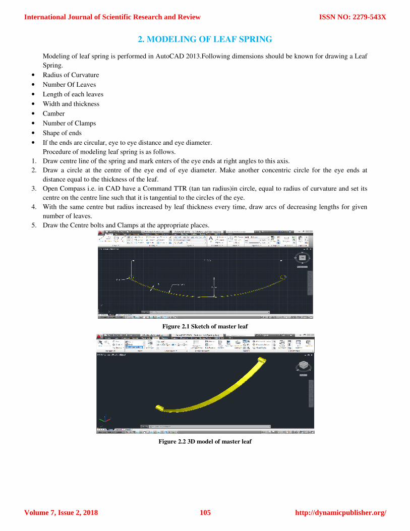
2. MODELING OF LEAF SPRING
Modeling of leaf spring is performed in AutoCAD 2013.Following dimensions should be known for drawing a Leaf
Spring.
• Radius of Curvature
• Number Of Leaves
• Length of each leaves
• Width and thickness
• Camber
• Number of Clamps
• Shape of ends
• If the ends are circular, eye to eye distance and eye diameter.
Procedure of modeling leaf spring is as follows.
1. Draw centre line of the spring and mark enters of the eye ends at right angles to this axis.
2. Draw a circle at the centre of the eye end of eye diameter. Make another concentric circle for the eye ends at
distance equal to the thickness of the leaf.
3. Open Compass i.e. in CAD have a Command TTR (tan tan radius)in circle, equal to radius of curvature and set its
centre on the centre line such that it is tangential to the circles of the eye.
4. With the same centre but radius increased by leaf thickness every time, draw arcs of decreasing lengths for given
number of leaves.
5. Draw the Centre bolts and Clamps at the appropriate places.
Figure 2.1 Sketch of master leaf
Figure 2.2 3D model of master leaf
International Journal of Scientific Research and Review
Volume 7, Issue 2, 2018
ISSN NO: 2279-543X
http://dynamicpublisher.org/105
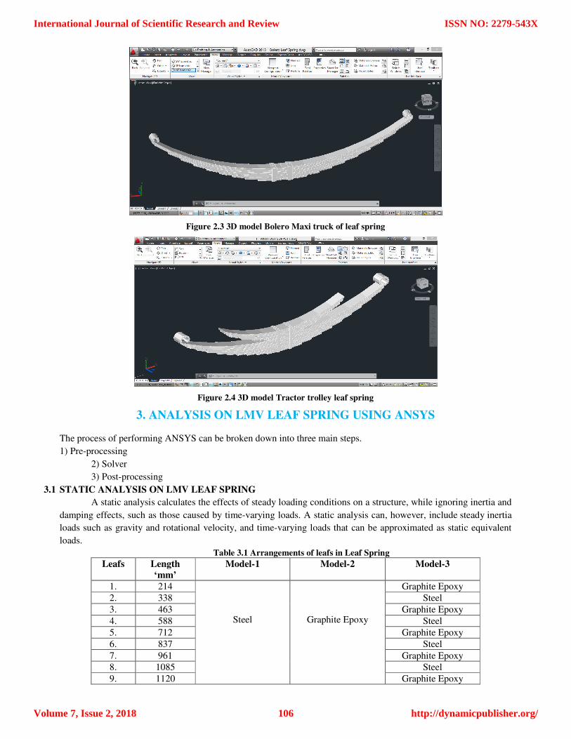
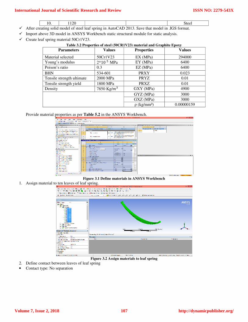
Figure 2.3 3D model Bolero Maxi truck of leaf spring
Figure 2.4 3D model Tractor trolley leaf spring
3. ANALYSIS ON LMV LEAF SPRING USING ANSYS
The process of performing ANSYS can be broken down into three main steps.
1) Pre-processing
2) Solver
3) Post-processing
3.1 STATIC ANALYSIS ON LMV LEAF SPRING
A static analysis calculates the effects of steady loading conditions on a structure, while ignoring inertia and
damping effects, such as those caused by time-varying loads. A static analysis can, however, include steady inertia
loads such as gravity and rotational velocity, and time-varying loads that can be approximated as static equivalent
loads.
Table 3.1 Arrangements of leafs in Leaf Spring
Leafs Length
‘mm’
Model-1 Model-2 Model-3
1. 214
Steel
Graphite Epoxy
Graphite Epoxy
2. 338 Steel
3. 463 Graphite Epoxy
4. 588 Steel
5. 712 Graphite Epoxy
6. 837 Steel
7. 961 Graphite Epoxy
8. 1085 Steel
9. 1120 Graphite Epoxy
International Journal of Scientific Research and Review
Volume 7, Issue 2, 2018
ISSN NO: 2279-543X
http://dynamicpublisher.org/106
10. 1120 Steel
� After creating solid model of steel leaf spring in AutoCAD 2013. Save that model in .IGS format.
� Import above 3D model in ANSYS Workbench static structural module for static analysis.
� Create leaf spring material 50Cr1V23.
Table 3.2 Properties of steel (50CR1V23) material and Graphite Epoxy
Parameters Values Properties Values
Material selected 50Cr1V23 EX (MPa) 294000
Young’s modulus 2*10 � MPa EY (MPa) 6400
Poison’s ratio 0.3 EZ (MPa) 6400
BHN 534-601 PRXY 0.023
Tensile strength ultimate 2000 MPa PRYZ 0.01
Tensile strength yield 1800 MPa PRXZ 0.01
Density 7850 Kg/�� GXY (MPa) 4900
GYZ (MPa) 3000
GXZ (MPa) 3000
ρ (kg/mm³) 0.00000159
Provide material properties as per Table 5.2 in the ANSYS Workbench.
Figure 3.1 Define materials in ANSYS Workbench
1. Assign material to ten leaves of leaf spring.
Figure 3.2 Assign materials to leaf spring
2. Define contact between leaves of leaf spring
• Contact type: No separation
International Journal of Scientific Research and Review
Volume 7, Issue 2, 2018
ISSN NO: 2279-543X
http://dynamicpublisher.org/107
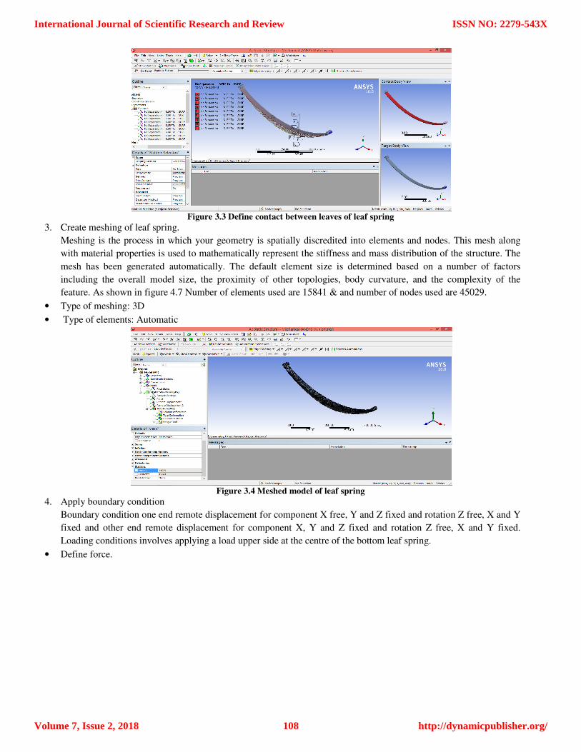
Figure 3.3 Define contact between leaves of leaf spring
3. Create meshing of leaf spring.
Meshing is the process in which your geometry is spatially discredited into elements and nodes. This mesh along
with material properties is used to mathematically represent the stiffness and mass distribution of the structure. The
mesh has been generated automatically. The default element size is determined based on a number of factors
including the overall model size, the proximity of other topologies, body curvature, and the complexity of the
feature. As shown in figure 4.7 Number of elements used are 15841 & and number of nodes used are 45029.
• Type of meshing: 3D
• Type of elements: Automatic
Figure 3.4 Meshed model of leaf spring
4. Apply boundary condition
Boundary condition one end remote displacement for component X free, Y and Z fixed and rotation Z free, X and Y
fixed and other end remote displacement for component X, Y and Z fixed and rotation Z free, X and Y fixed.
Loading conditions involves applying a load upper side at the centre of the bottom leaf spring.
• Define force.
International Journal of Scientific Research and Review
Volume 7, Issue 2, 2018
ISSN NO: 2279-543X
http://dynamicpublisher.org/108
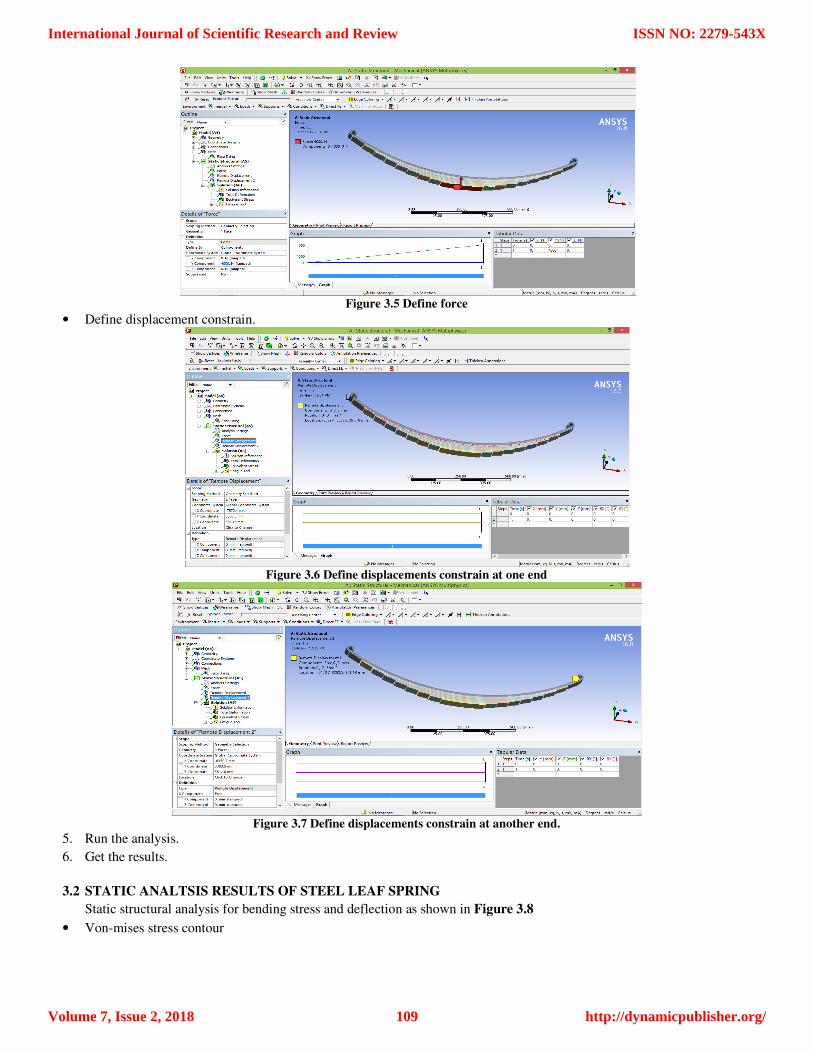
Figure 3.5 Define force
• Define displacement constrain.
Figure 3.6 Define displacements constrain at one end
Figure 3.7 Define displacements constrain at another end.
5. Run the analysis.
6. Get the results.
3.2 STATIC ANALTSIS RESULTS OF STEEL LEAF SPRING
Static structural analysis for bending stress and deflection as shown in Figure 3.8
• Von-mises stress contour
International Journal of Scientific Research and Review
Volume 7, Issue 2, 2018
ISSN NO: 2279-543X
http://dynamicpublisher.org/109
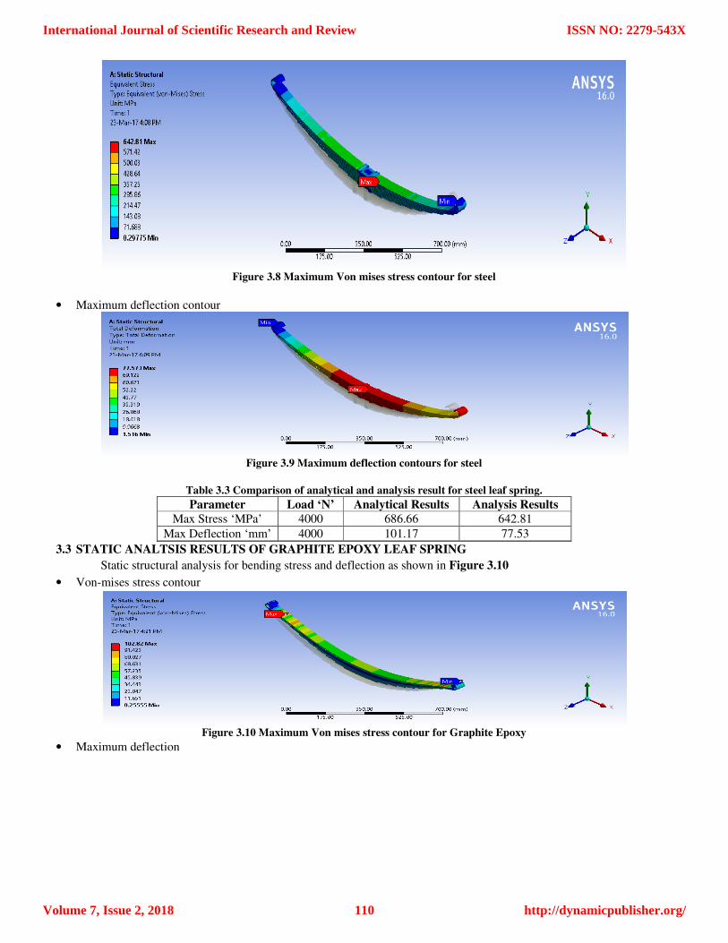
Figure 3.8 Maximum Von mises stress contour for steel
• Maximum deflection contour
Figure 3.9 Maximum deflection contours for steel
Table 3.3 Comparison of analytical and analysis result for steel leaf spring.
Parameter Load ‘N’ Analytical Results Analysis Results
Max Stress ‘MPa’ 4000 686.66 642.81
Max Deflection ‘mm’ 4000 101.17 77.53
3.3 STATIC ANALTSIS RESULTS OF GRAPHITE EPOXY LEAF SPRING
Static structural analysis for bending stress and deflection as shown in Figure 3.10
• Von-mises stress contour
Figure 3.10 Maximum Von mises stress contour for Graphite Epoxy
• Maximum deflection
International Journal of Scientific Research and Review
Volume 7, Issue 2, 2018
ISSN NO: 2279-543X
http://dynamicpublisher.org/110
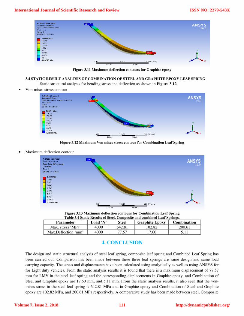
Figure 3.11 Maximum deflection contours for Graphite epoxy
3.4 STATIC RESULT ANALTSIS OF COMBINATION OF STEEL AND GRAPHITE EPOXY LEAF SPRING
Static structural analysis for bending stress and deflection as shown in Figure 3.12
• Von-mises stress contour
Figure 3.12 Maximum Von mises stress contour for Combination Leaf Spring
• Maximum deflection contour
Figure 3.13 Maximum deflection contours for Combination Leaf Spring
Table 3.4 Static Results of Steel, Composite and combined Leaf Springs.
Parameter Load ‘N’ Steel Graphite Epoxy Combination
Max. stress ‘MPa’ 4000 642.81 102.82 200.61
Max.Deflection ‘mm’ 4000 77.57 17.60 5.11
4. CONCLUSION
The design and static structural analysis of steel leaf spring, composite leaf spring and Combined Leaf Spring has
been carried out. Comparison has been made between these three leaf springs are same design and same load
carrying capacity. The stress and displacements have been calculated using analytically as well as using ANSYS for
for Light duty vehicles. From the static analysis results it is found that there is a maximum displacement of 77.57
mm for LMV in the steel leaf spring and the corresponding displacements in Graphite epoxy, and Combination of
Steel and Graphite epoxy are 17.60 mm, and 5.11 mm. From the static analysis results, it also seen that the von-
mises stress in the steel leaf spring is 642.81 MPa and in Graphite epoxy and Combination of Steel and Graphite
epoxy are 102.82 MPa, and 200.61 MPa respectively. A comparative study has been made between steel, Composite
International Journal of Scientific Research and Review
Volume 7, Issue 2, 2018
ISSN NO: 2279-543X
http://dynamicpublisher.org/111
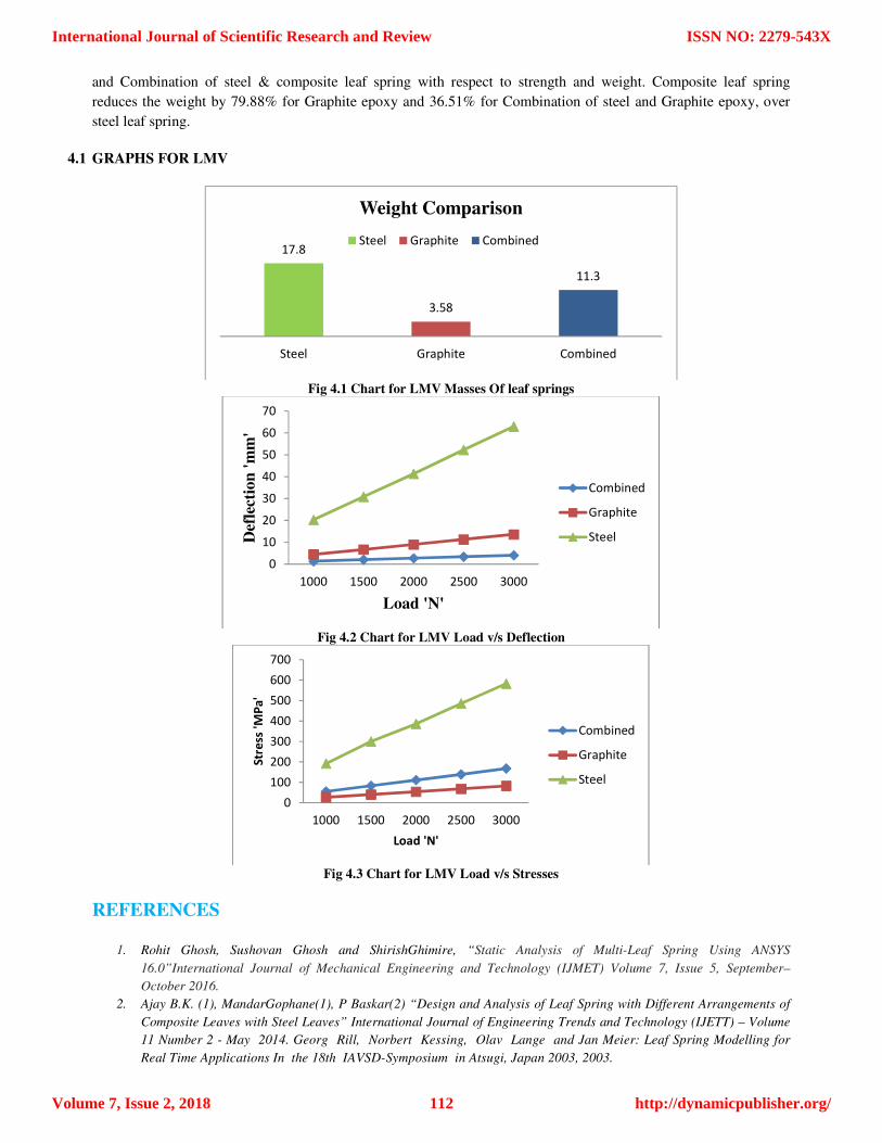
and Combination of steel & composite leaf spring with respect to strength and weight. Composite leaf spring
reduces the weight by 79.88% for Graphite epoxy and 36.51% for Combination of steel and Graphite epoxy, over
steel leaf spring.
4.1 GRAPHS FOR LMV
Fig 4.1 Chart for LMV Masses Of leaf springs
Fig 4.2 Chart for LMV Load v/s Deflection
Fig 4.3 Chart for LMV Load v/s Stresses
REFERENCES
1. Rohit Ghosh, Sushovan Ghosh and ShirishGhimire, “Static Analysis of Multi-Leaf Spring Using ANSYS
16.0”International Journal of Mechanical Engineering and Technology (IJMET) Volume 7, Issue 5, September–
October 2016.
2. Ajay B.K. (1), MandarGophane(1), P Baskar(2) “Design and Analysis of Leaf Spring with Different Arrangements of
Composite Leaves with Steel Leaves” International Journal of Engineering Trends and Technology (IJETT) – Volume
11 Number 2 - May 2014. Georg Rill, Norbert Kessing, Olav Lange and Jan Meier: Leaf Spring Modelling for
Real Time Applications In the 18th IAVSD-Symposium in Atsugi, Japan 2003, 2003.
17.8
3.58
11.3
Steel Graphite Combined
Weight Comparison
Steel Graphite Combined
0
10
20
30
40
50
60
70
1000 1500 2000 2500 3000
Def
lect
ion
'm
m'
Load 'N'
Combined
Graphite
Steel
0
100
200
300
400
500
600
700
1000 1500 2000 2500 3000
Str
ess '
MP
a'
Load 'N'
Combined
Graphite
Steel
International Journal of Scientific Research and Review
Volume 7, Issue 2, 2018
ISSN NO: 2279-543X
http://dynamicpublisher.org/112

3. Mohammed Liyaquat Ali Farooqui “Design And Assessment of Multi-Layer Leaf Spring Design and analysis of
composite leaf spring”International Journal of Mechanical Engineering and Technology (IJMET) Volume 7, Issue 5,
September–October 2016.
4. Mahmood M. Shokrieh, DavoodRezaei, “Analysis and optimization of a composite leaf spring”, Composite Structures
60 (2003) 317–325
5. M.Venkatesan, D.Helmen, “Design and analysis of composite leaf spring in light vehicle”, International Journal of
Modern Engineering Research, Vol.2, Issue.1, 2012, pp 213-218
6. Kumar Krishan, Aggarwal M.L, “Computer aided FEA comparison of mono steel and mono GRP leaf spring”,
International Journal of Advanced Engineering Research and Studies, Vol. I, Issue II, 2012, pp 155-158.
7. N. P. Dhoshi, Prof. N. K. Ingole, Prof. U. D. Gulhane, “Analysis and modification of leaf spring of tractor trailer using
analytical and finite element method”, International Journal of Modern Engineering Research, Vol.1, Issue.2, pp 719-
722.
8. K. K. Jadhao, DR. R. S. Dalu, “Experimental investigation & numerical analysis of composite leaf spring”,
International Journal of Engineering Science and Technology, Vol. 3, No. 6, 2011.
International Journal of Scientific Research and Review
Volume 7, Issue 2, 2018
ISSN NO: 2279-543X
http://dynamicpublisher.org/113