Embed Size (px)
Citation preview
Deploying Oracle 11gR2 Real Application Clusters on the Cisco Unified Computing
System with EMC CLARiiON Storage
Cisco Validated Design
September 2010
© 2010 Cisco Systems, Inc. All rights reserved. This document is Cisco Public Information. Cisco Validated Design Page 2
Contents
What You Will Learn ................................................................................................................................. 3 Introduction ............................................................................................................................................... 3
Leadership from Cisco ......................................................................................................................... 3 Oracle Certified Configuration .............................................................................................................. 3 Benefits of the Configuration ................................................................................................................ 3
High-Performance Platform for Oracle RAC .................................................................................... 4 Safer Deployments with Certified and Validated Configurations ..................................................... 4
Implementation Instructions ................................................................................................................. 4 Introducing the Cisco Unified Computing System .................................................................................... 5
Comprehensive Management .............................................................................................................. 5 Radical Simplification ........................................................................................................................... 5 High Performance................................................................................................................................. 5 Scalability Decoupled from Complexity ................................................................................................ 5 Ready for the Future............................................................................................................................. 5
Overview of the Certified Configuration .................................................................................................... 5 Overview of the Solution ........................................................................................................................... 8
Detailed Topology................................................................................................................................. 9 Configuring Cisco Unified Computing System for the Eight-Node Oracle RAC ..................................... 11
Configuring the Cisco UCS 6120XP Fabric Interconnect................................................................... 11 Configuring the Server Ports .............................................................................................................. 11 Configuring Uplinks to the SAN and LAN ........................................................................................... 12 Configuring the SAN and LAN on Cisco UCS Manager ..................................................................... 12
Setting up Service Profiles ...................................................................................................................... 14 Creating the Service Profile Template................................................................................................ 15 Creating and Associating the vNICs With VLANs .............................................................................. 19 Creating and Associating Service Profiles With Blade Servers ......................................................... 22
Configuring the SAN Switch and Zoning ................................................................................................ 24 Setting Up EMC CLARiiON Storage ....................................................................................................... 25
Configuring Storage............................................................................................................................ 25 Applying Patches, Environment, and OS Settings ............................................................................. 28 Installing the OS and Setting up the Environment ............................................................................. 29
Oracle 11gR2 Clusterware and the Database ........................................................................................ 33 Installing Oracle Clusterware and the Database ................................................................................ 34 Database and Workload Configuration .............................................................................................. 34
OLTP Database ............................................................................................................................. 35 DSS Database ............................................................................................................................... 36 STRAC Database ........................................................................................................................... 36 Additional Configuration ................................................................................................................. 36
Testing Workload Performance .......................................................................................................... 38 OLTP Workload .............................................................................................................................. 39 DSS Workload ................................................................................................................................ 39
FCoE Traffic ....................................................................................................................................... 40 Availability after Hardware Failures ........................................................................................................ 41 Conclusion .............................................................................................................................................. 42 For More Information .............................................................................................................................. 43 Appendix A - Cisco Unified Computing System Kernel Settings (/etc/sysctl.conf) ................................. 44 Appendix B - Oracle RAC 11gR2 Database Instances Configuration .................................................... 45 Appendix C - DNS and GNS Setup and Configuration .......................................................................... 51
© 2010 Cisco Systems, Inc. All rights reserved. This document is Cisco Public Information. Cisco Validated Design Page 3
What You Will Learn This document describes how the Cisco Unified Computing System™ can be used in conjunction with EMC®
CLARiiON® storage systems to implement an Oracle Real Application Clusters (RAC) solution that is an Oracle
Certified Configuration. The Cisco Unified Computing System provides the compute, network, and storage access
components of the cluster, deployed as a single cohesive system. The result is an implementation that addresses
many of the challenges that database administrators and their IT departments face today, including needs for a
simplified deployment and operation model, high performance for Oracle RAC software, and lower total cost of
ownership (TCO). The document introduces the Cisco Unified Computing System and provides instructions for
implementing it; it concludes with an analysis of the cluster‘s performance and reliability characteristics.
Introduction Data powers essentially every operation in a modern enterprise, from keeping the supply chain operating
efficiently to managing relationships with customers. Oracle RAC brings an innovative approach to the challenges
of rapidly increasing amounts of data and demand for high performance. Oracle RAC uses a horizontal scaling (or
scale-out) model that allows organizations to take advantage of the fact that the price of one-to-four-socket x86-
architecture servers continues to drop while their processing power increases unabated. The clustered approach
allows each server to contribute its processing power to the overall cluster‘s capacity, enabling a new approach to
managing the cluster‘s performance and capacity.
Leadership from Cisco Cisco is the undisputed leader in providing network connectivity in enterprise data centers. With the introduction
of the Cisco Unified Computing System, Cisco is now equipped to provide the entire clustered infrastructure for
Oracle RAC deployments. The Cisco Unified Computing System provides compute, network, virtualization, and
storage access resources that are centrally controlled and managed as a single cohesive system. With the
capability to scale to up to 320 servers and incorporate both blade and rack-mount servers in a single system, the
Cisco Unified Computing System provides an ideal foundation for Oracle RAC deployments.
Historically, enterprise database management systems have run on costly symmetric multiprocessing servers that
use a vertical scaling (or scale-up) model. However, as the cost of one-to-four-socket x86-architecture servers
continues to drop while their processing power increases, a new model has emerged. Oracle RAC uses a
horizontal scaling, or scale-out, model, in which the active-active cluster uses multiple servers, each contributing
its processing power to the cluster, increasing performance, scalability, and availability. The cluster balances the
workload across the servers in the cluster, and the cluster can provide continuous availability in the event of a
failure.
Oracle Certified Configuration All components in an Oracle RAC implementation must work together flawlessly, and Cisco has worked closely
with EMC and Oracle to create, test, and certify a configuration of Oracle RAC on the Cisco Unified Computing
System. Cisco‘s Oracle Certified Configurations provide an implementation of Oracle Database with Real
Application Clusters technology consistent with industry best practices. For back-end Fibre Channel storage, the
certification environment included an EMC CLARiiON storage system with a mix of Fibre Channel drives and
state-of-the-art Flash Drives (FDs) to further speed performance.
Benefits of the Configuration The Oracle Certified Configuration of Oracle RAC on the Cisco Unified Computing System offers a number of
important benefits.
Simplified Deployment and Operation Because the entire cluster runs on a single cohesive system, database administrators no longer need to
painstakingly configure each element in the hardware stack independently. The system‘s compute, network, and
storage-access resources are essentially stateless, provisioned dynamically by Cisco® UCS Manager. This role-

© 2010 Cisco Systems, Inc. All rights reserved. This document is Cisco Public Information. Cisco Validated Design Page 4
and policy-based embedded management system handles every aspect of system configuration, from a server‘s
firmware and identity settings to the network connections that connect storage traffic to the destination storage
system. This capability dramatically simplifies the process of scaling an Oracle RAC configuration or rehosting an
existing node on an upgrade server. Cisco UCS Manager uses the concept of service profiles and service profile
templates to consistently and accurately configure resources. The system automatically configures and deploys
servers in minutes, rather than the hours or days required by traditional systems composed of discrete, separately
managed components. Indeed, Cisco UCS Manager can simplify server deployment to the point where it can
automatically discover, provision, and deploy a new blade server when it is inserted into a chassis.
The system is based on a 10-Gbps unified network fabric that radically simplifies cabling at the rack level by
consolidating both IP and Fibre Channel traffic onto the same rack-level 10-Gbps converged network. This ―wire-
once‖ model allows in-rack network cabling to be configured once, with network features and configurations all
implemented by changes in software rather than by error-prone changes in physical cabling. This Oracle Certified
Configuration not only supports physically separate public and private networks; it provides redundancy with
automatic failover.
High-Performance Platform for Oracle RAC
The Cisco UCS B-Series Blade Servers used in this certified configuration feature Intel Xeon 5500 series
processors that deliver intelligent performance, automated energy efficiency, and flexible virtualization. Intel Turbo
Boost Technology automatically boosts processing power through increased frequency and use of hyperthreading
to deliver high performance when workloads demand and thermal conditions permit.
The patented Cisco Extended Memory Technology offers twice the memory footprint (384 GB) of any other server
using 8-GB DIMMs, or the economical option of a 192-GB memory footprint using inexpensive 4-GB DIMMs. Both
choices for large memory footprints can help speed database performance by allowing more data to be cached in
memory.
The Cisco Unified Computing System‘s 10-Gbps unified fabric delivers standards-based Ethernet and Fibre
Channel over Ethernet (FCoE) capabilities that simplify and secure rack-level cabling while speeding network
traffic compared to traditional Gigabit Ethernet networks. The balanced resources of the Cisco Unified Computing
System allow the system to easily process an intensive online transaction processing (OLTP) and decision-
support system (DSS) workload with no resource saturation.
Safer Deployments with Certified and Validated Configurations
Cisco and Oracle are working together to promote interoperability of Oracle‘s next-generation database and
application solutions with the Cisco Unified Computing System, helping make the Cisco Unified Computing
System a simple and reliable platform on which to run Oracle software. In addition to the certified Oracle RAC
configuration described in this document, Cisco, Oracle and EMC have:
● Completed an Oracle Validated Configuration for Cisco Unified Computing System running Oracle
Enterprise Linux running directly on the hardware or in a virtualized environment running Oracle VM
● Certified single-instance database implementations of Oracle Database 11gR2 on Oracle Enterprise Linux
and Red Hat Enterprise Linux 5.4
Implementation Instructions This document introduces the Cisco Unified Computing System and discusses the ways it addresses many of the
challenges that database administrators and their IT departments face today. The document provides an overview
of the certified Oracle RAC configuration along with instructions for setting up the Cisco Unified Computing
System and the EMC CLARiiON storage system, including database table setup and the use of Flash drives. The
document reports on Cisco‘s performance measurements for the cluster and a reliability analysis that
demonstrates how the system continues operation even when commonly encountered hardware faults occur.
© 2010 Cisco Systems, Inc. All rights reserved. This document is Cisco Public Information. Cisco Validated Design Page 5
Introducing the Cisco Unified Computing System The Cisco Unified Computing System addresses many of the challenges faced by database administrators and
their IT departments, making it an ideal platform for Oracle RAC implementations.
Comprehensive Management The system uses an embedded, end-to-end management system that uses a high-availability active-standby
configuration. Cisco UCS Manager uses role and policy-based management that allows IT departments to
continue to use subject-matter experts to define server, network, and storage access policy. After a server and its
identity, firmware, configuration, and connectivity are defined, the server, or a number of servers like it, can be
deployed in minutes, rather than the hours or days that it typically takes to move a server from the loading dock to
production use. This capability relieves database administrators from tedious, manual assembly of individual
components and makes scaling an Oracle RAC configuration a straightforward process.
Radical Simplification The Cisco Unified Computing System represents a radical simplification compared to the way that servers and
networks are deployed today. It reduces network access-layer fragmentation by eliminating switching inside the
blade server chassis. It integrates compute resources on a unified I/O fabric that supports standard IP protocols
as well as Fibre Channel through FCoE encapsulation. The system eliminates the limitations of fixed I/O
configurations with an I/O architecture that can be changed through software on a per-server basis to provide
needed connectivity using a just-in-time deployment model. The result of this radical simplification is fewer
switches, cables, adapters, and management points, helping reduce cost, complexity, power needs, and cooling
overhead.
High Performance The system‘s blade servers are based on the Intel Xeon 5500 and 7500 series processors. These processors
adapt performance to application demands, increasing the clock rate on specific processor cores as workload and
thermal conditions permit. These processors, combined with patented Cisco Extended Memory Technology,
deliver database performance along with the memory footprint needed to support large in-server caches. The
system is integrated within a 10 Gigabit Ethernet–based unified fabric that delivers the throughput and low-latency
characteristics needed to support the demands of the cluster‘s public network, storage traffic, and high-volume
cluster messaging traffic.
Scalability Decoupled from Complexity The system used to create the certified configuration is designed to be highly scalable, with up to 40 blade
chassis and 320 blade servers connected by a single pair of low-latency, lossless fabric interconnects. New
compute resources can be put into service quickly, enabling Oracle RAC configurations to be scaled on demand,
and with the compute resources they require.
Ready for the Future The system gives Oracle RAC room to scale while anticipating future technology investments. The blade server
chassis, power supplies, and midplane are capable of handling future servers with even greater processing
capacity. Likewise, the chassis is built to support future 40 Gigabit Ethernet standards when they become
available.
Overview of the Certified Configuration The Cisco Unified Computing System used for the certified configuration is based on Cisco B-Series Blade
Servers; however, the breadth of Cisco‘s server and network product line suggests that similar product
combinations will meet the same requirements. The Cisco Unified Computing System uses a form-factor-neutral
architecture that will allow Cisco C-Series Rack-Mount Servers to be integrated as part of the system using
capabilities planned to follow the product‘s first customer shipment (FCS). Similarly, the system‘s core

© 2010 Cisco Systems, Inc. All rights reserved. This document is Cisco Public Information. Cisco Validated Design Page 6
components -- high-performance compute resources integrated using a unified fabric -- can be integrated
manually today using Cisco C-Series servers and Cisco Nexus™ 5000 Series Switches.
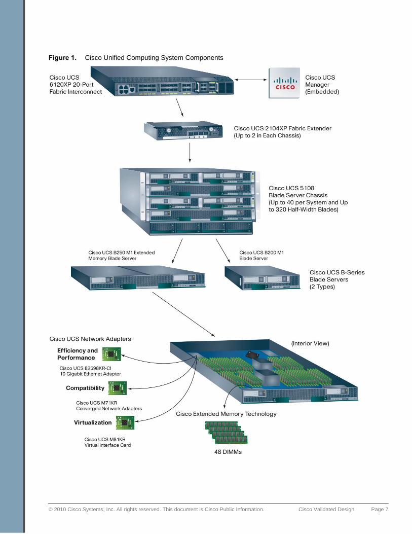
The system used to create the Oracle Certified Configuration is built from the hierarchy of components illustrated
in Figure 1:
● The Cisco UCS 6120XP 20-Port Fabric Interconnect provides low-latency, lossless, 10-Gbps unified fabric
connectivity for the cluster. The interconnect provides connectivity to blade server chassis and the
enterprise IP network. Through an 8-port, 4-Gbps Fibre Channel expansion card, the interconnect provides
native Fibre Channel access to the EMC CLARiiON storage system. Two fabric interconnects are
configured in the cluster, providing physical separation between the public and private networks and also
providing the capability to securely host both networks in the event of a failure.
● The Cisco UCS 2104XP Fabric Extender brings the unified fabric into each blade server chassis. The fabric
extender is configured and managed by the fabric interconnects, eliminating the complexity of blade-server-
resident switches. Two fabric extenders are configured in each of the cluster‘s two blade server chassis.
Each one uses two of the four available 10-Gbps uplinks to connect to one of the two fabric interconnects.
● The Cisco UCS 5108 Blade Server Chassis houses the fabric extenders, up to four power supplies, and up
to eight blade servers. As part of the system‘s radical simplification, the blade server chassis is also
managed by the fabric interconnects, eliminating another point of management. Two chassis were
configured for the Oracle RAC described in this document.
The blade chassis supports up to eight half-width blades or up to four full-width blades. The certified
configuration uses eight (four in each chassis) Cisco UCS B200 M1 Blade Servers, each equipped with two
quad-core Intel Xeon 5500 series processors at 2.93 GHz. Each blade server was configured with 24 GB of
memory. A memory footprint of up to 384 GB can be accommodated through the use of a Cisco UCS B250
M1 Extended Memory Blade Server.
● The blade server form factor supports a range of mezzanine-format Cisco UCS network adapters, including
a 10 Gigabit Ethernet network adapter designed for efficiency and performance, the Cisco UCS M81KR
Virtual Interface Card designed to deliver the system‘s full support for virtualization, and a set of Cisco UCS
M71KR converged network adapters designed for full compatibility with existing Ethernet and Fibre
Channel environments. These adapters present both an Ethernet network interface card (NIC) and a Fibre
Channel host bus adapter (HBA) to the host operating system. They make the existence of the unified
fabric transparent to the operating system, passing traffic from both the NIC and the HBA onto the unified
fabric. Versions are available with either Emulex or QLogic HBA silicon; the certified configuration uses a
Cisco UCS M71KR-Q QLogic Converged Network Adapter that provides 20-Gbps of connectivity by
connecting to each of the chassis fabric extenders.
© 2010 Cisco Systems, Inc. All rights reserved. This document is Cisco Public Information. Cisco Validated Design Page 7
Figure 1. Cisco Unified Computing System Components
© 2010 Cisco Systems, Inc. All rights reserved. This document is Cisco Public Information. Cisco Validated Design Page 8
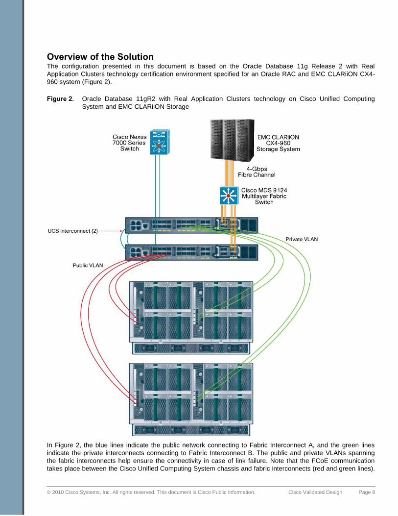
Overview of the Solution The configuration presented in this document is based on the Oracle Database 11g Release 2 with Real
Application Clusters technology certification environment specified for an Oracle RAC and EMC CLARiiON CX4-
960 system (Figure 2).
Figure 2. Oracle Database 11gR2 with Real Application Clusters technology on Cisco Unified Computing
System and EMC CLARiiON Storage
In Figure 2, the blue lines indicate the public network connecting to Fabric Interconnect A, and the green lines
indicate the private interconnects connecting to Fabric Interconnect B. The public and private VLANs spanning
the fabric interconnects help ensure the connectivity in case of link failure. Note that the FCoE communication
takes place between the Cisco Unified Computing System chassis and fabric interconnects (red and green lines).
© 2010 Cisco Systems, Inc. All rights reserved. This document is Cisco Public Information. Cisco Validated Design Page 9
This is a typical configuration that can be deployed in a customer's environment. The best practices and setup
recommendations are described in subsequent sections of this document.
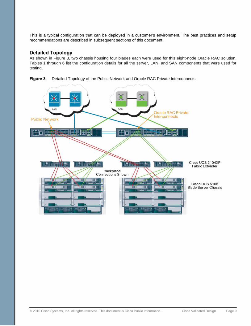
Detailed Topology As shown in Figure 3, two chassis housing four blades each were used for this eight-node Oracle RAC solution.
Tables 1 through 6 list the configuration details for all the server, LAN, and SAN components that were used for
testing.
Figure 3. Detailed Topology of the Public Network and Oracle RAC Private Interconnects
© 2010 Cisco Systems, Inc. All rights reserved. This document is Cisco Public Information. Cisco Validated Design Page 10
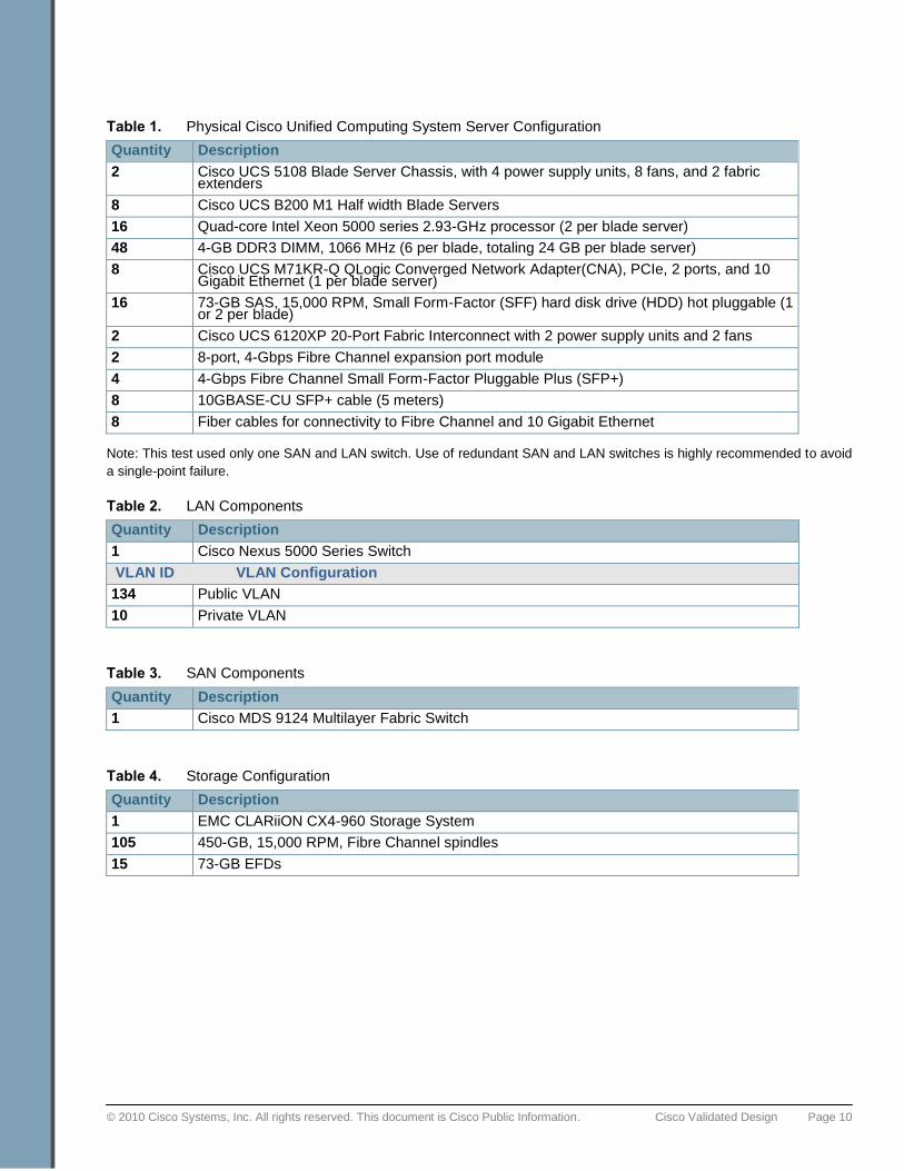
Table 1. Physical Cisco Unified Computing System Server Configuration
Quantity Description
2 Cisco UCS 5108 Blade Server Chassis, with 4 power supply units, 8 fans, and 2 fabric extenders
8 Cisco UCS B200 M1 Half width Blade Servers
16 Quad-core Intel Xeon 5000 series 2.93-GHz processor (2 per blade server)
48 4-GB DDR3 DIMM, 1066 MHz (6 per blade, totaling 24 GB per blade server)
8 Cisco UCS M71KR-Q QLogic Converged Network Adapter(CNA), PCIe, 2 ports, and 10 Gigabit Ethernet (1 per blade server)
16 73-GB SAS, 15,000 RPM, Small Form-Factor (SFF) hard disk drive (HDD) hot pluggable (1 or 2 per blade)
2 Cisco UCS 6120XP 20-Port Fabric Interconnect with 2 power supply units and 2 fans
2 8-port, 4-Gbps Fibre Channel expansion port module
4 4-Gbps Fibre Channel Small Form-Factor Pluggable Plus (SFP+)
8 10GBASE-CU SFP+ cable (5 meters)
8 Fiber cables for connectivity to Fibre Channel and 10 Gigabit Ethernet
Note: This test used only one SAN and LAN switch. Use of redundant SAN and LAN switches is highly recommended to avoid
a single-point failure.
Table 2. LAN Components
Quantity Description
1 Cisco Nexus 5000 Series Switch
VLAN ID VLAN Configuration
134 Public VLAN
10 Private VLAN
Table 3. SAN Components
Quantity Description
1 Cisco MDS 9124 Multilayer Fabric Switch
Table 4. Storage Configuration
Quantity Description
1 EMC CLARiiON CX4-960 Storage System
105 450-GB, 15,000 RPM, Fibre Channel spindles
15 73-GB EFDs
© 2010 Cisco Systems, Inc. All rights reserved. This document is Cisco Public Information. Cisco Validated Design Page 11
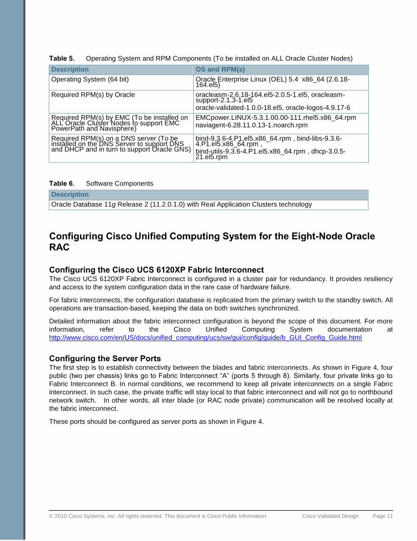
Table 5. Operating System and RPM Components (To be installed on ALL Oracle Cluster Nodes)
Description OS and RPM(s)
Operating System (64 bit) Oracle Enterprise Linux (OEL) 5.4 x86_64 (2.6.18-164.el5)
Required RPM(s) by Oracle oracleasm-2.6.18-164.el5-2.0.5-1.el5, oracleasm-support-2.1.3-1.el5 oracle-validated-1.0.0-18.el5, oracle-logos-4.9.17-6
Required RPM(s) by EMC (To be installed on ALL Oracle Cluster Nodes to support EMC PowerPath and Navisphere)
EMCpower.LINUX-5.3.1.00.00-111.rhel5.x86_64.rpm naviagent-6.28.11.0.13-1.noarch.rpm
Required RPM(s) on a DNS server (To be installed on the DNS Server to support DNS and DHCP and in turn to support Oracle GNS)
bind-9.3.6-4.P1.el5.x86_64.rpm , bind-libs-9.3.6-4.P1.el5.x86_64.rpm , bind-utils-9.3.6-4.P1.el5.x86_64.rpm , dhcp-3.0.5-21.el5.rpm
Table 6. Software Components
Description
Oracle Database 11g Release 2 (11.2.0.1.0) with Real Application Clusters technology
Configuring Cisco Unified Computing System for the Eight-Node Oracle RAC
Configuring the Cisco UCS 6120XP Fabric Interconnect The Cisco UCS 6120XP Fabric Interconnect is configured in a cluster pair for redundancy. It provides resiliency
and access to the system configuration data in the rare case of hardware failure.
For fabric interconnects, the configuration database is replicated from the primary switch to the standby switch. All
operations are transaction-based, keeping the data on both switches synchronized.
Detailed information about the fabric interconnect configuration is beyond the scope of this document. For more
information, refer to the Cisco Unified Computing System documentation at
http://www.cisco.com/en/US/docs/unified_computing/ucs/sw/gui/config/guide/b_GUI_Config_Guide.html
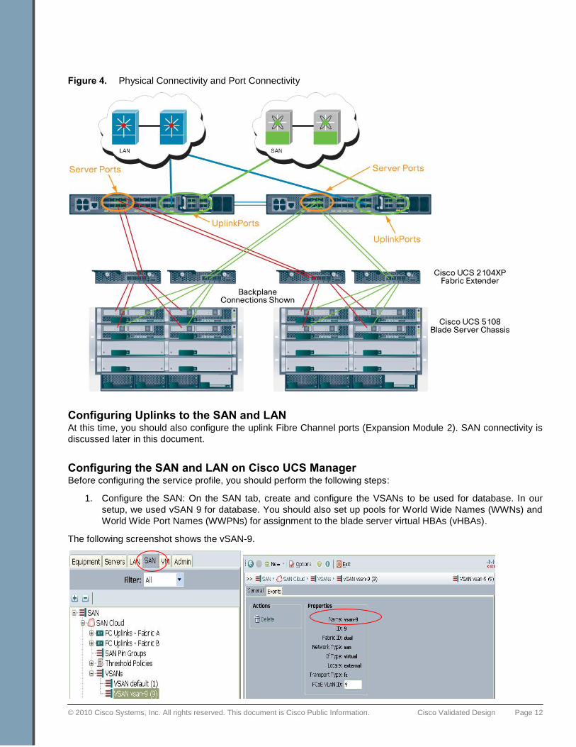
Configuring the Server Ports The first step is to establish connectivity between the blades and fabric interconnects. As shown in Figure 4, four
public (two per chassis) links go to Fabric Interconnect ―A‖ (ports 5 through 8). Similarly, four private links go to
Fabric Interconnect B. In normal conditions, we recommend to keep all private interconnects on a single Fabric
interconnect. In such case, the private traffic will stay local to that fabric interconnect and will not go to northbound
network switch. In other words, all inter blade (or RAC node private) communication will be resolved locally at
the fabric interconnect.
These ports should be configured as server ports as shown in Figure 4.
© 2010 Cisco Systems, Inc. All rights reserved. This document is Cisco Public Information. Cisco Validated Design Page 12
Figure 4. Physical Connectivity and Port Connectivity
Configuring Uplinks to the SAN and LAN At this time, you should also configure the uplink Fibre Channel ports (Expansion Module 2). SAN connectivity is
discussed later in this document.
Configuring the SAN and LAN on Cisco UCS Manager Before configuring the service profile, you should perform the following steps:
1. Configure the SAN: On the SAN tab, create and configure the VSANs to be used for database. In our
setup, we used vSAN 9 for database. You should also set up pools for World Wide Names (WWNs) and
World Wide Port Names (WWPNs) for assignment to the blade server virtual HBAs (vHBAs).
The following screenshot shows the vSAN-9.
© 2010 Cisco Systems, Inc. All rights reserved. This document is Cisco Public Information. Cisco Validated Design Page 13
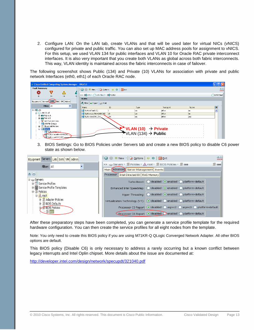
2. Configure LAN: On the LAN tab, create VLANs and that will be used later for virtual NICs (vNICS)
configured for private and public traffic. You can also set up MAC address pools for assignment to vNICS.
For this setup, we used VLAN 134 for public interfaces and VLAN 10 for Oracle RAC private interconnect
interfaces. It is also very important that you create both VLANs as global across both fabric interconnects.
This way, VLAN identity is maintained across the fabric interconnects in case of failover.
The following screenshot shows Public (134) and Private (10) VLANs for association with private and public
network Interfaces (eth0, eth1) of each Oracle RAC node.
3. BIOS Settings: Go to BIOS Policies under Servers tab and create a new BIOS policy to disable C6 power
state as shown below.
After these preparatory steps have been completed, you can generate a service profile template for the required
hardware configuration. You can then create the service profiles for all eight nodes from the template.
Note: You only need to create this BIOS policy if you are using M71KR-Q QLogic Converged Network Adapter. All other BIOS
options are default.
This BIOS policy (Disable C6) is only necessary to address a rarely occurring but a known conflict between
legacy interrupts and Intel Oplin chipset. More details about the issue are documented at:
http://developer.intel.com/design/network/specupdt/321040.pdf
VLAN (10) Private VLAN (134) Public
© 2010 Cisco Systems, Inc. All rights reserved. This document is Cisco Public Information. Cisco Validated Design Page 14
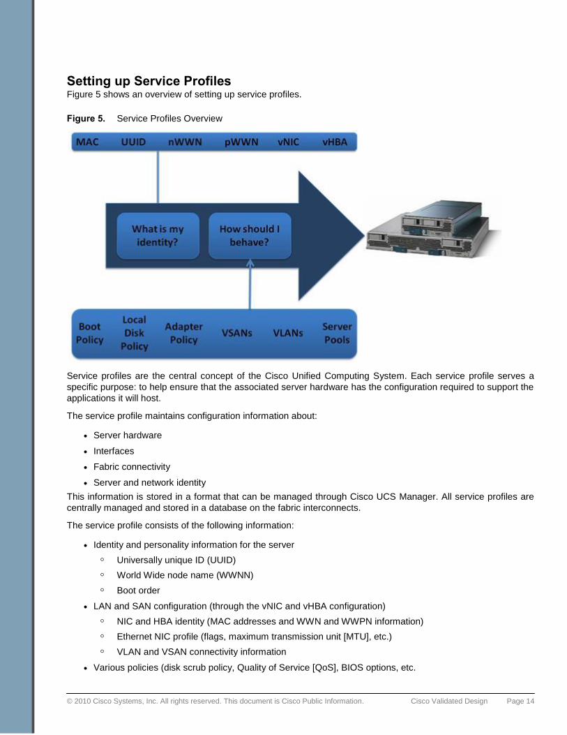
Setting up Service Profiles Figure 5 shows an overview of setting up service profiles.
Figure 5. Service Profiles Overview
Service profiles are the central concept of the Cisco Unified Computing System. Each service profile serves a
specific purpose: to help ensure that the associated server hardware has the configuration required to support the
applications it will host.
The service profile maintains configuration information about:
● Server hardware
● Interfaces
● Fabric connectivity
● Server and network identity
This information is stored in a format that can be managed through Cisco UCS Manager. All service profiles are
centrally managed and stored in a database on the fabric interconnects.
The service profile consists of the following information:
● Identity and personality information for the server
◦ Universally unique ID (UUID)
◦ World Wide node name (WWNN)
◦ Boot order
● LAN and SAN configuration (through the vNIC and vHBA configuration)
◦ NIC and HBA identity (MAC addresses and WWN and WWPN information)
◦ Ethernet NIC profile (flags, maximum transmission unit [MTU], etc.)
◦ VLAN and VSAN connectivity information
● Various policies (disk scrub policy, Quality of Service [QoS], BIOS options, etc.
© 2010 Cisco Systems, Inc. All rights reserved. This document is Cisco Public Information. Cisco Validated Design Page 15
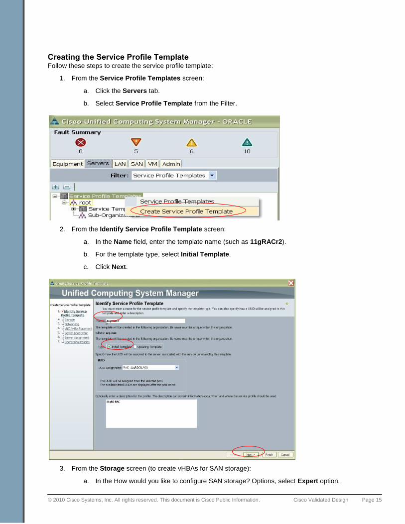
Creating the Service Profile Template Follow these steps to create the service profile template:
1. From the Service Profile Templates screen:
a. Click the Servers tab.
b. Select Service Profile Template from the Filter.
2. From the Identify Service Profile Template screen:
a. In the Name field, enter the template name (such as 11gRACr2).
b. For the template type, select Initial Template.
c. Click Next.
3. From the Storage screen (to create vHBAs for SAN storage):
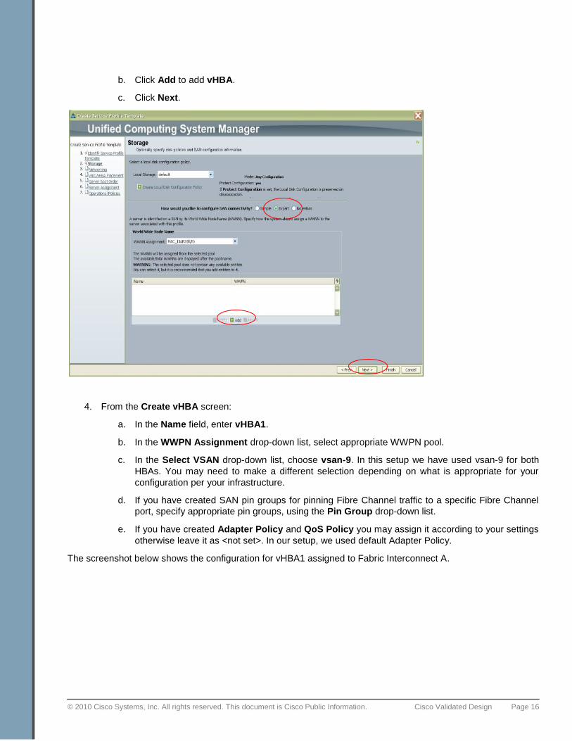
a. In the How would you like to configure SAN storage? Options, select Expert option.
© 2010 Cisco Systems, Inc. All rights reserved. This document is Cisco Public Information. Cisco Validated Design Page 16
b. Click Add to add vHBA.
c. Click Next.
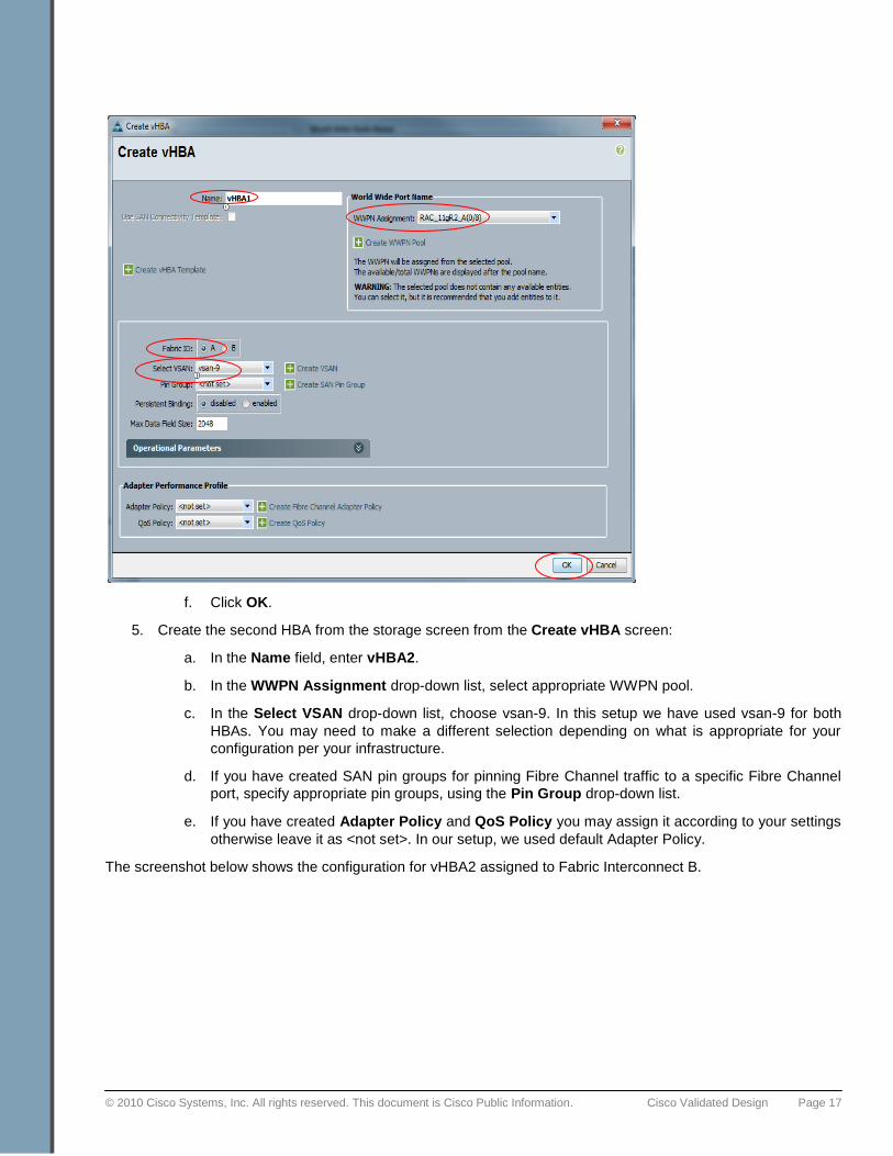
4. From the Create vHBA screen:
a. In the Name field, enter vHBA1.
b. In the WWPN Assignment drop-down list, select appropriate WWPN pool.
c. In the Select VSAN drop-down list, choose vsan-9. In this setup we have used vsan-9 for both
HBAs. You may need to make a different selection depending on what is appropriate for your
configuration per your infrastructure.
d. If you have created SAN pin groups for pinning Fibre Channel traffic to a specific Fibre Channel
port, specify appropriate pin groups, using the Pin Group drop-down list.
e. If you have created Adapter Policy and QoS Policy you may assign it according to your settings
otherwise leave it as <not set>. In our setup, we used default Adapter Policy.
The screenshot below shows the configuration for vHBA1 assigned to Fabric Interconnect A.
© 2010 Cisco Systems, Inc. All rights reserved. This document is Cisco Public Information. Cisco Validated Design Page 17
f. Click OK.
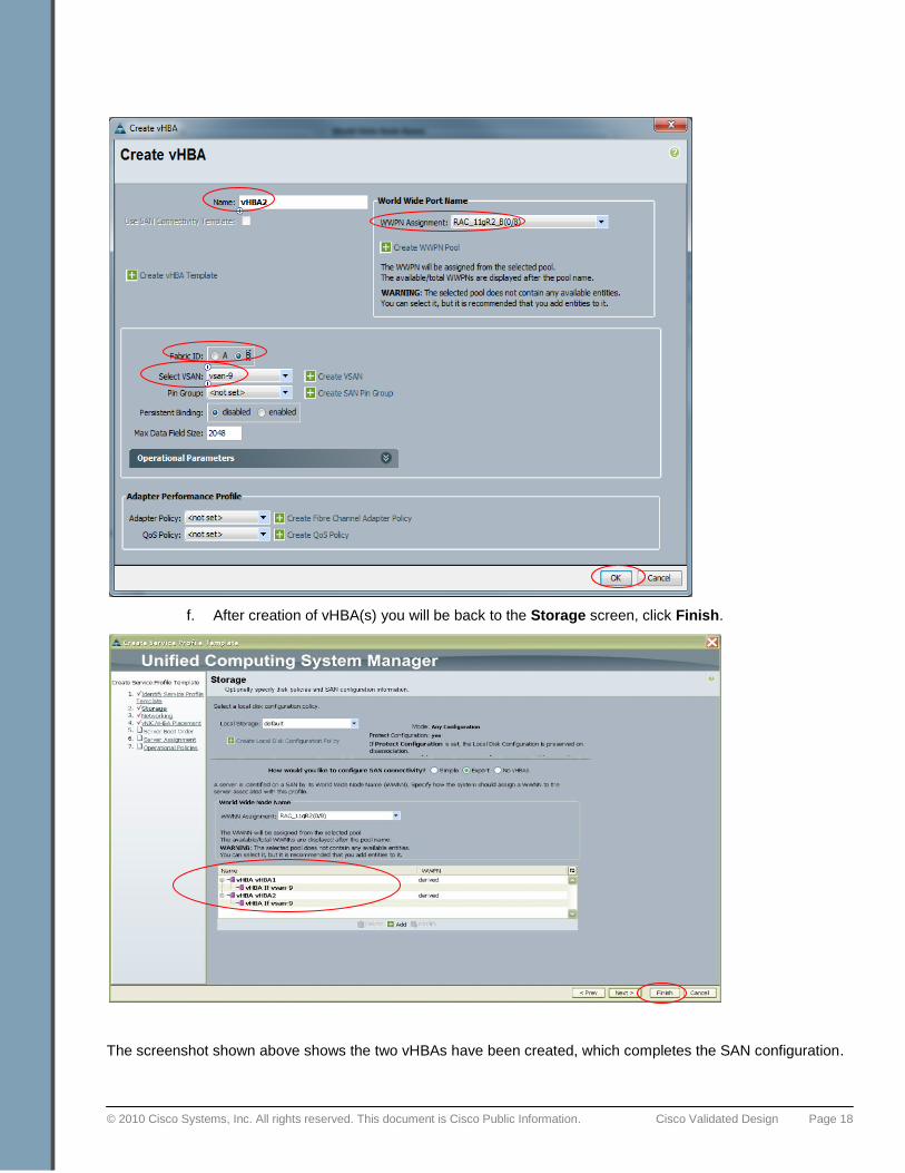
5. Create the second HBA from the storage screen from the Create vHBA screen:
a. In the Name field, enter vHBA2.
b. In the WWPN Assignment drop-down list, select appropriate WWPN pool.
c. In the Select VSAN drop-down list, choose vsan-9. In this setup we have used vsan-9 for both
HBAs. You may need to make a different selection depending on what is appropriate for your
configuration per your infrastructure.
d. If you have created SAN pin groups for pinning Fibre Channel traffic to a specific Fibre Channel
port, specify appropriate pin groups, using the Pin Group drop-down list.
e. If you have created Adapter Policy and QoS Policy you may assign it according to your settings
otherwise leave it as <not set>. In our setup, we used default Adapter Policy.
The screenshot below shows the configuration for vHBA2 assigned to Fabric Interconnect B.
© 2010 Cisco Systems, Inc. All rights reserved. This document is Cisco Public Information. Cisco Validated Design Page 18
f. After creation of vHBA(s) you will be back to the Storage screen, click Finish.
The screenshot shown above shows the two vHBAs have been created, which completes the SAN configuration.
© 2010 Cisco Systems, Inc. All rights reserved. This document is Cisco Public Information. Cisco Validated Design Page 19
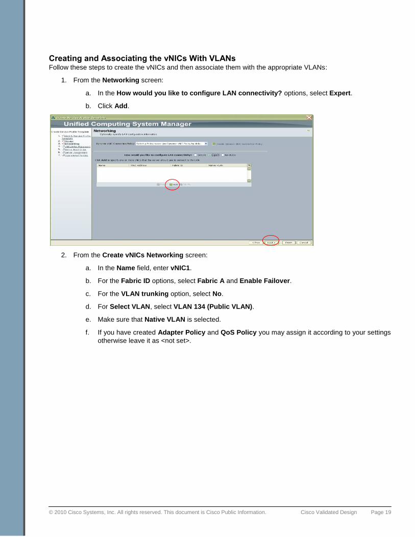
Creating and Associating the vNICs With VLANs Follow these steps to create the vNICs and then associate them with the appropriate VLANs:
1. From the Networking screen:
a. In the How would you like to configure LAN connectivity? options, select Expert.
b. Click Add.
2. From the Create vNICs Networking screen:
a. In the Name field, enter vNIC1.
b. For the Fabric ID options, select Fabric A and Enable Failover.
c. For the VLAN trunking option, select No.
d. For Select VLAN, select VLAN 134 (Public VLAN).
e. Make sure that Native VLAN is selected.
f. If you have created Adapter Policy and QoS Policy you may assign it according to your settings
otherwise leave it as <not set>.
© 2010 Cisco Systems, Inc. All rights reserved. This document is Cisco Public Information. Cisco Validated Design Page 20
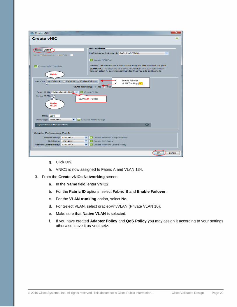
g. Click OK.
h. VNIC1 is now assigned to Fabric A and VLAN 134.
3. From the Create vNICs Networking screen:
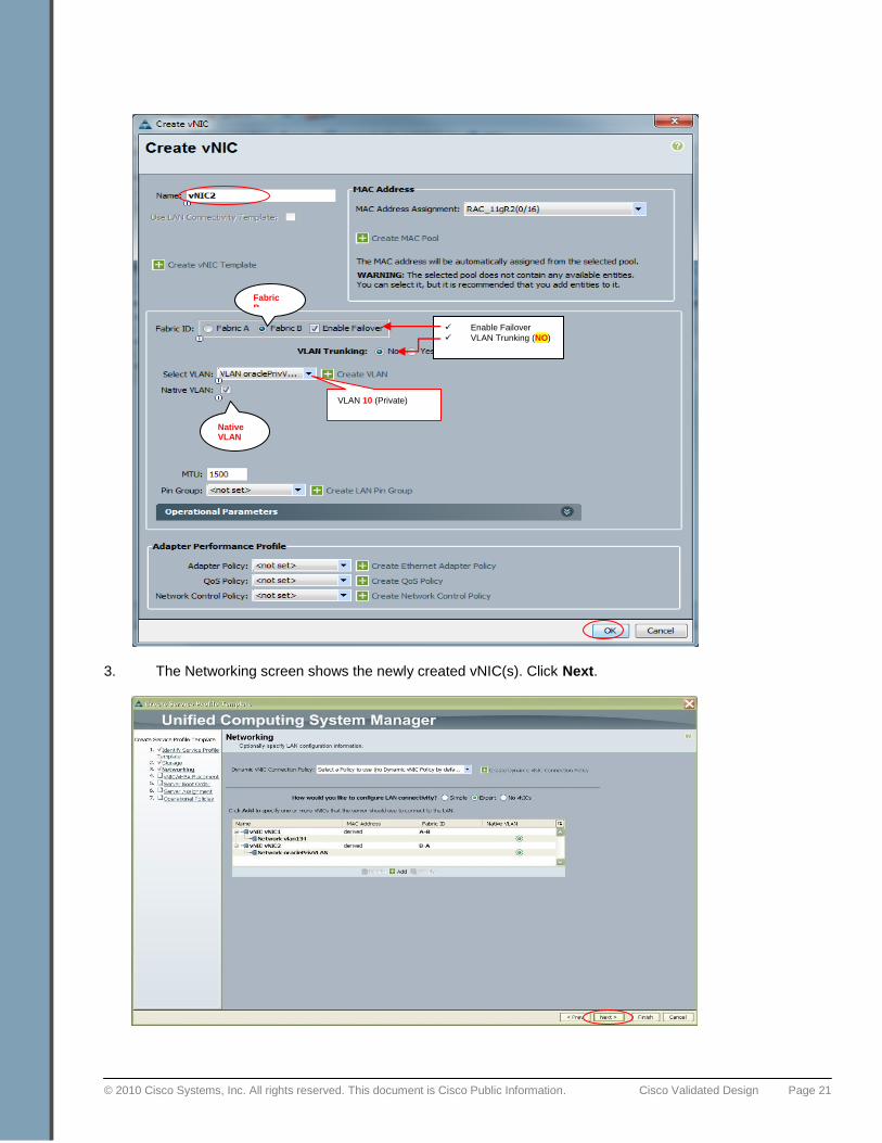
a. In the Name field, enter vNIC2.
b. For the Fabric ID options, select Fabric B and Enable Failover.
c. For the VLAN trunking option, select No.
d. For Select VLAN, select oraclepPrivVLAN (Private VLAN 10).
e. Make sure that Native VLAN is selected.
f. If you have created Adapter Policy and QoS Policy you may assign it according to your settings
otherwise leave it as <not set>.
Fabric A
VLAN 134 (Public)
Native VLAN
Enable Failover
VLAN Trunking (NO)
© 2010 Cisco Systems, Inc. All rights reserved. This document is Cisco Public Information. Cisco Validated Design Page 21
3. The Networking screen shows the newly created vNIC(s). Click Next.
VLAN 10 (Private)
Fabric B
Native VLAN
Enable Failover
VLAN Trunking (NO)
© 2010 Cisco Systems, Inc. All rights reserved. This document is Cisco Public Information. Cisco Validated Design Page 22
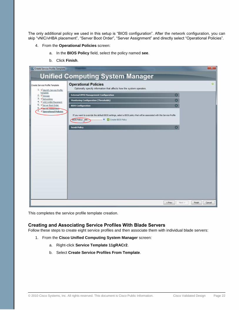
The only additional policy we used in this setup is ―BIOS configuration‖. After the network configuration, you can
skip ―vNIC/vHBA placement‖, ―Server Boot Order‖, ―Server Assignment‖ and directly select ―Operational Policies‖.
4. From the Operational Policies screen:
a. In the BIOS Policy field, select the policy named see.
b. Click Finish.
This completes the service profile template creation.
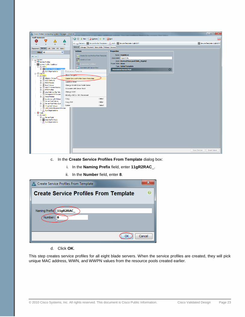
Creating and Associating Service Profiles With Blade Servers Follow these steps to create eight service profiles and then associate them with individual blade servers:
1. From the Cisco Unified Computing System Manager screen:
a. Right-click Service Template 11gRACr2.
b. Select Create Service Profiles From Template.
© 2010 Cisco Systems, Inc. All rights reserved. This document is Cisco Public Information. Cisco Validated Design Page 23
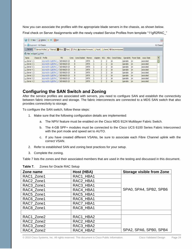
c. In the Create Service Profiles From Template dialog box:
i. In the Naming Prefix field, enter 11gR2RAC_.
ii. In the Number field, enter 8.
d. Click OK.
This step creates service profiles for all eight blade servers. When the service profiles are created, they will pick
unique MAC address, WWN, and WWPN values from the resource pools created earlier.
© 2010 Cisco Systems, Inc. All rights reserved. This document is Cisco Public Information. Cisco Validated Design Page 24
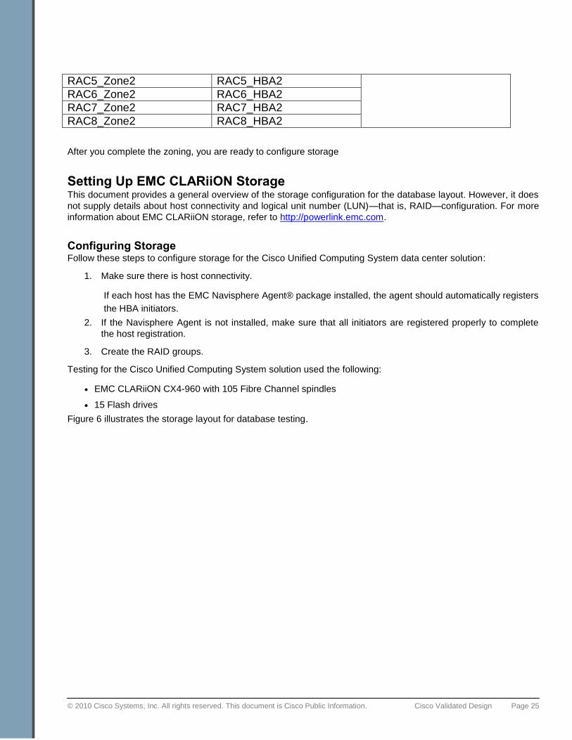
Now you can associate the profiles with the appropriate blade servers in the chassis, as shown below.
Final check on Server Assignments with the newly created Service Profiles from template ―11gR2RAC_‖
Configuring the SAN Switch and Zoning After the service profiles are associated with servers, you need to configure SAN and establish the connectivity
between fabric interconnect and storage. The fabric interconnects are connected to a MDS SAN switch that also
provides connectivity to storage.
To configure the SAN switch, follow these steps:
1. Make sure that the following configuration details are implemented:
a. The NPIV feature must be enabled on the Cisco MDS 9124 Multilayer Fabric Switch.
b. The 4-GB SPF+ modules must be connected to the Cisco UCS 6100 Series Fabric Interconnect
with the port mode and speed set to AUTO.
c. If you have created different VSANs, be sure to associate each Fibre Channel uplink with the
correct VSAN.
2. Refer to established SAN and zoning best practices for your setup.
3. Complete the zoning.
Table 7 lists the zones and their associated members that are used in the testing and discussed in this document.
Table 7. Zones for Oracle RAC Setup
Zone name Host (HBA) Storage visible from Zone
RAC1_Zone1 RAC1_HBA1 SPA0, SPA4, SPB2, SPB6
RAC2_Zone1 RAC2_HBA1
RAC3_Zone1 RAC3_HBA1
RAC4_Zone1 RAC4_HBA1
RAC5_Zone1 RAC5_HBA1
RAC6_Zone1 RAC6_HBA1
RAC7_Zone1 RAC7_HBA1
RAC8_Zone1 RAC8_HBA1
RAC1_Zone2 RAC1_HBA2 SPA2, SPA6, SPB0, SPB4
RAC2_Zone2 RAC2_HBA2
RAC3_Zone2 RAC3_HBA2
RAC4_Zone2 RAC4_HBA2
© 2010 Cisco Systems, Inc. All rights reserved. This document is Cisco Public Information. Cisco Validated Design Page 25
RAC5_Zone2 RAC5_HBA2
RAC6_Zone2 RAC6_HBA2
RAC7_Zone2 RAC7_HBA2
RAC8_Zone2 RAC8_HBA2
After you complete the zoning, you are ready to configure storage
Setting Up EMC CLARiiON Storage This document provides a general overview of the storage configuration for the database layout. However, it does
not supply details about host connectivity and logical unit number (LUN)—that is, RAID—configuration. For more
information about EMC CLARiiON storage, refer to http://powerlink.emc.com.
Configuring Storage Follow these steps to configure storage for the Cisco Unified Computing System data center solution:
1. Make sure there is host connectivity.
If each host has the EMC Navisphere Agent® package installed, the agent should automatically registers
the HBA initiators.
2. If the Navisphere Agent is not installed, make sure that all initiators are registered properly to complete
the host registration.
3. Create the RAID groups.
Testing for the Cisco Unified Computing System solution used the following:
● EMC CLARiiON CX4-960 with 105 Fibre Channel spindles
● 15 Flash drives
Figure 6 illustrates the storage layout for database testing.
© 2010 Cisco Systems, Inc. All rights reserved. This document is Cisco Public Information. Cisco Validated Design Page 26
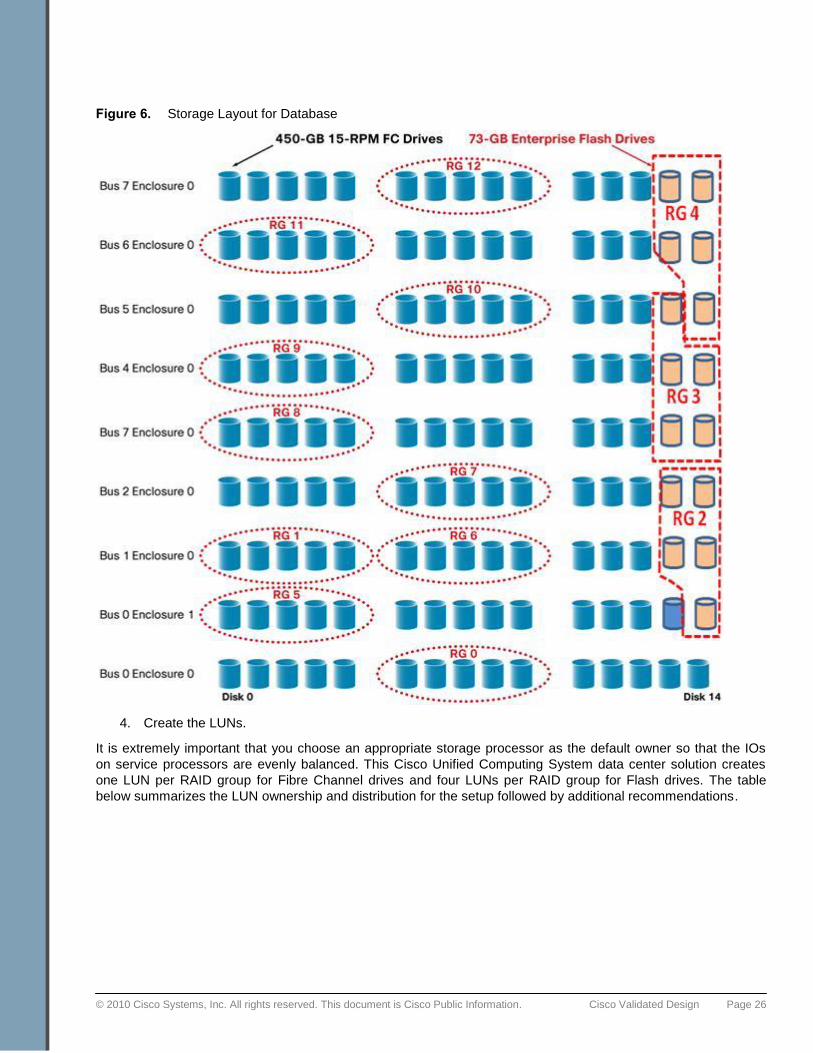
Figure 6. Storage Layout for Database
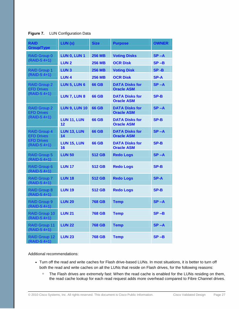
4. Create the LUNs.
It is extremely important that you choose an appropriate storage processor as the default owner so that the IOs
on service processors are evenly balanced. This Cisco Unified Computing System data center solution creates
one LUN per RAID group for Fibre Channel drives and four LUNs per RAID group for Flash drives. The table
below summarizes the LUN ownership and distribution for the setup followed by additional recommendations.
© 2010 Cisco Systems, Inc. All rights reserved. This document is Cisco Public Information. Cisco Validated Design Page 27
Figure 7. LUN Configuration Data
RAID Group/Type
LUN (s) Size Purpose OWNER
RAID Group 0 (RAID-5 4+1)
LUN 0, LUN 1 256 MB Voting Disks SP –A
LUN 2 256 MB OCR Disk SP –B
RAID Group 1 (RAID-5 4+1)
LUN 3 256 MB Voting Disk SP -B
LUN 4 256 MB OCR Disk SP-A
RAID Group 2 EFD Drives (RAID-5 4+1)
LUN 5, LUN 6 66 GB DATA Disks for Oracle ASM
SP –A
LUN 7, LUN 8 66 GB DATA Disks for Oracle ASM
SP-B
RAID Group 2 EFD Drives (RAID-5 4+1)
LUN 9, LUN 10 66 GB DATA Disks for Oracle ASM
SP –A
LUN 11, LUN 12
66 GB DATA Disks for Oracle ASM
SP-B
RAID Group 4 EFD Drives EFD Drives (RAID-5 4+1)
LUN 13, LUN 14
66 GB DATA Disks for Oracle ASM
SP –A
LUN 15, LUN 16
66 GB DATA Disks for Oracle ASM
SP-B
RAID Group 5 (RAID-5 4+1)
LUN 50 512 GB Redo Logs SP –A
RAID Group 6 (RAID-5 4+1)
LUN 17 512 GB Redo Logs SP-B
RAID Group 7 (RAID-5 4+1)
LUN 18 512 GB Redo Logs SP-A
RAID Group 8 (RAID-5 4+1)
LUN 19 512 GB Redo Logs SP-B
RAID Group 9 (RAID-5 4+1)
LUN 20 768 GB Temp SP –A
RAID Group 10 (RAID-5 4+1)
LUN 21 768 GB Temp SP –B
RAID Group 11 (RAID-5 4+1)
LUN 22 768 GB Temp SP –A
RAID Group 12 (RAID-5 4+1)
LUN 23 768 GB Temp SP –B
Additional recommendations:
● Turn off the read and write caches for Flash drive-based LUNs. In most situations, it is better to turn off
both the read and write caches on all the LUNs that reside on Flash drives, for the following reasons:
◦ The Flash drives are extremely fast: When the read cache is enabled for the LUNs residing on them,
the read cache lookup for each read request adds more overhead compared to Fibre Channel drives.

© 2010 Cisco Systems, Inc. All rights reserved. This document is Cisco Public Information. Cisco Validated Design Page 28
This scenario occurs in an application profile that is not expected to get many read cache hits at any
rate. It is generally much faster to directly read the block from the Flash drive.
◦ In typical situations, the storage array is also shared by several other applications and the database.
This situation occurs particularly when storage deploys mixed drives, which may also consist of
slower SATA drives. The write cache may become fully saturated, placing the Flash drives in a force-
flush situation, which adds latency. Therefore, it is better in these situations to write the block directly
to the Flash drives than to the write cache of the storage system.
◦ Distribute database files for Flash drives. Refer to the table below for recommendations about
distributing database files based on the type of workload.
Table 8. Distribution of Data Files Based on Type of Workload
EFD-Friendly DB Workloads Not as Cost-Effective on EFD
User Tablespace Based Data Files Random Reads B-Tree leaf access
ROWID look up into Table
Access to out-of-line LOB
Access to overflowed row
Index scan over Unclustered Table
Compression: Increases I/O intensity (IOPS/GB)
Serial Reads
Random Writes
Row update by PK
Index maintenance
Reduce checkpoint interval
Temp Tablespace Files - Sort Areas and Intermediate Tables Sequentially read and written but I/O done
in 1 MB units: not enough to amortize seeks.
Lower Latency: Get In, Get Out
Redo Log Files Sequential I/O
Read and write and commit latency already handled by cache in storage controller
Undo Tablespace Sequential writes and randomly read
by Oracle Flashback.
Generally, reads are for recently written data that is likely to be in the buffer cache
Large Table Scans (if single stream)
The configuration described here employs most of EMC‘s best practices and recommendations for LUN
distribution in the database. It also adopts the layout for a mixed storage environment consisting of Fibre Channel
disks and Flash drives.
For more information about Oracle database best practices for flash-drive-based EMC CLARiiON storage, refer to
the document ―Leveraging EMC CLARiiON CX4 with Enterprise Flash Drives for Oracle Database Deployments‖
at http://www.emc.com/collateral/hardware/white-papers/h5967-leveraging-clariion-cx4-oracle-deploy-wp.pdf.
Applying Patches, Environment, and OS Settings The following is the summary for 8-node Oracle RAC setup.
Oracle 11gR2 – Cisco UCS Certification test bed setup:
1. 8 Node RAC Cluster on CISCO UCS B200-M1 Half width blades
2. EMC CLARiiON CX4-960 Storage

© 2010 Cisco Systems, Inc. All rights reserved. This document is Cisco Public Information. Cisco Validated Design Page 29
3. FCoE (Carries 10GigE Ethernet and Fiber Channel Traffic)
4. CISCO M71KR-Q CNA.
5. Oracle Enterprise Linux (OEL) 5 Update 4, 64-bit
6. 11gR2 Grid Infrastructure and Oracle Real Application Clusters
7. 3 ASM Disk Groups
a. ASMDG: Contains Voting and OCR disks.
Note: It is not mandatory to create a separate diskgroup for OCR and Voting disks.
b. DATADG: Contains All Data and Temp tablespaces using Flash drives.
c. REDODG: Contains All Redo Logs
After completing the configuration of the Cisco Unified Computing System, the SAN, and storage, you are ready
to install the OS.
Installing the OS and Setting up the Environment Follow these steps to install the OS and other required packages to enable the RAC environment settings:
1. Install 64-bit Oracle Enterprise Linux (OEL) 5.4, on all eight nodes (During OS install, select packages
shown below)
a. Install the following RPM(s) by choosing from the options:
i. Oracle Validated Configuration RPM package
The Oracle Validated Configuration RPM sets and verifies system parameters based on
recommendations from the Oracle Validated Configurations program, and installs any
additional packages needed for Oracle Clusterware and database installation. It also
updates sysctl.conf settings, system startup parameters, user limits, and driver
parameters to Oracle recommended values.
ii. Linux ASMLib RPMs.
Oracle recommends that you use ASM for database file management, and install the
Linux ASMLIB RPMs to simplify administration. ASMLib 2.0 is delivered as a set of three
Linux RPM packages:
oracleasmlib-2.0 - the ASM libraries
oracleasm-support-2.0 - utilities needed to administer ASMLib
oracleasm - a kernel module for the ASM library
Please refer to Oracle documentation to identify the kernel and appropriate RPM packages.
2. Install the EMC Navisphere Agent RPM package on all the nodes (naviagent-6.28.11.0.13-1)
The EMC Navisphere Host Agent is server-based software that communicates with Navisphere client
applications, such as the Navisphere Command Line Interface (CLI) and Manager. A host agent
automatically registers hosts and HBAs and also provides drive mapping information for the UI and CLI.
3. Install the EMC PowerPath RPM package on all nodes (EMCpower.LINUX-5.3.1.00.00-111)
EMC PowerPath software is a server-resident, performance and application availability enhancing
software solution. PowerPath combines multiple path I/O capabilities, automatic load balancing, and path
failover functions into one integrated package. Here are the basic commands to install and configure
PowerPath. Please refer to PowerPath documentation for detailed information.
© 2010 Cisco Systems, Inc. All rights reserved. This document is Cisco Public Information. Cisco Validated Design Page 30
Install the EMC PowerPath rpm
rpm -ivh EMCpower.LINUX-5.3.1.00.00-111.rhel5.x86_64.rpm
Install the license key
emcpreg -add xxxx-xxxx-xxxx
Confirm license key installation
powermt check_registration
Save the License
powermt save
Start powerpath
/etc/init.d/PowerPath start
Checking if powerpath has been installed.
powermt display dev=all
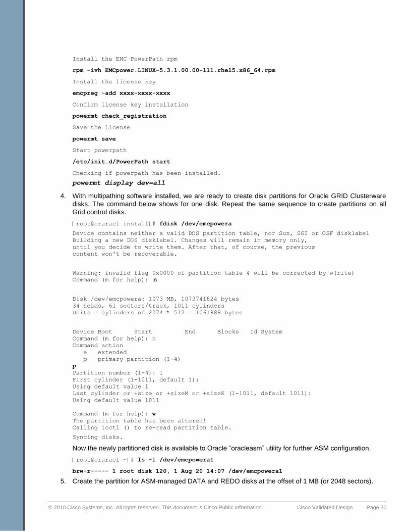
4. With multipathing software installed, we are ready to create disk partitions for Oracle GRID Clusterware
disks. The command below shows for one disk. Repeat the same sequence to create partitions on all
Grid control disks.
[root@orarac1 install]# fdisk /dev/emcpowera
Device contains neither a valid DOS partition table, nor Sun, SGI or OSF disklabel
Building a new DOS disklabel. Changes will remain in memory only,
until you decide to write them. After that, of course, the previous
content won't be recoverable.
Warning: invalid flag 0x0000 of partition table 4 will be corrected by w(rite)
Command (m for help): n
Disk /dev/emcpowera: 1073 MB, 1073741824 bytes
34 heads, 61 sectors/track, 1011 cylinders
Units = cylinders of 2074 * 512 = 1061888 bytes
Device Boot Start End Blocks Id System
Command (m for help): n
Command action
e extended
p primary partition (1-4)
p
Partition number (1-4): 1
First cylinder (1-1011, default 1):
Using default value 1
Last cylinder or +size or +sizeM or +sizeK (1-1011, default 1011):
Using default value 1011
Command (m for help): w
The partition table has been altered!
Calling ioctl () to re-read partition table.
Syncing disks.
Now the newly partitioned disk is available to Oracle ―oracleasm‖ utility for further ASM configuration.
[root@orarac1 ~]# ls -l /dev/emcpowera1
brw-r----- 1 root disk 120, 1 Aug 20 14:07 /dev/emcpowera1
5. Create the partition for ASM-managed DATA and REDO disks at the offset of 1 MB (or 2048 sectors).

© 2010 Cisco Systems, Inc. All rights reserved. This document is Cisco Public Information. Cisco Validated Design Page 31
The 1MB partition header offset is recommended for CLARiiON storage due to the fact that when doing
parity RAID (e.g. RAID-5 or RAID-6), CLARiiON uses a patented parity rotation scheme that shifts the
parity data to a different drive after multiple stripes of data as opposed to every data stripe. With this
parity rotation scheme, 1MB worth of data, that actually represents multiple default parity RAID stripes
worth of data, would have the data pieces all stored consecutives on all but one (R5) or two (R6) drives,
and with the parity for those multiple full data stripes stored completely on the same drive (R5) or drives
(R6). As long as application is storing data in 1MB units, aligned on 1MB offset within the LUNs, all 1MB
data chunk accesses will only involve reading data from the data spindles, and the drives holding the
parity will not be involved. If the reads are not aligned on 1MB LUN boundaries, the opportunity would
then exist that the same 1MB of data would have to be satisfied from reading uneven amount of data
from all the drives in that RAID group.
Use the following setup to create partitions for ASM–managed data disks, for example:
[root@orarac1 install]# fdisk /dev/emcpowerf
n new partition
p primary partition
1 partition 1
(CR) start from beginning of device or LUN
(CR) use all the available sectors
x go into EXPERT mode
b adjust partition header data begin offset
1 for partition 1
2048 to sector 2048 from beginning of LUN, or 1MB
w commit changes
The above step will create partition /dev/emcpowerf1 which can be used for DATA_1 for
Oracle ASM. Repeat same procedure to create partitions for the rest of the DATA, REDO
disks as well.
6. After all the partitions are created, you are ready to configure the ASM kernel module and stamp the ASM
disks.
Note: These are sample commands and the purpose is to highlight logical steps for the Oracle configuration. Please refer to
Oracle documentation for step-by-step install and detailed configuration.
● With the ASMLib RPMs installed, configure the ASM kernel module on all the nodes.
[root@orarac1 tmp]# /usr/sbin/oracleasm configure -i
Configuring the Oracle ASM library driver.
This will configure the on-boot properties of the Oracle ASM library
driver. The following questions will determine whether the driver is
loaded on boot and what permissions it will have. The current values
will be shown in brackets ('[]'). Hitting <ENTER> without typing an
answer will keep that current value. Ctrl-C will abort.
Default user to own the driver interface []: grid
Default group to own the driver interface []: asmadmin
Start Oracle ASM library driver on boot (y/n) [n]: y
Scan for Oracle ASM disks on boot (y/n) [y]: y
Writing Oracle ASM library driver configuration: done
---------------------------------------------------------------------------------
© 2010 Cisco Systems, Inc. All rights reserved. This document is Cisco Public Information. Cisco Validated Design Page 32
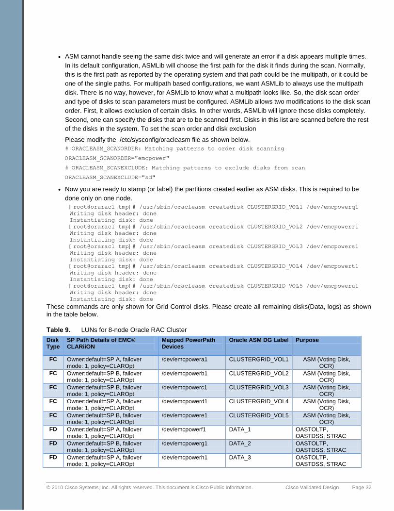
● ASM cannot handle seeing the same disk twice and will generate an error if a disk appears multiple times.
In its default configuration, ASMLib will choose the first path for the disk it finds during the scan. Normally,
this is the first path as reported by the operating system and that path could be the multipath, or it could be
one of the single paths. For multipath based configurations, we want ASMLib to always use the multipath
disk. There is no way, however, for ASMLib to know what a multipath looks like. So, the disk scan order
and type of disks to scan parameters must be configured. ASMLib allows two modifications to the disk scan
order. First, it allows exclusion of certain disks. In other words, ASMLib will ignore those disks completely.
Second, one can specify the disks that are to be scanned first. Disks in this list are scanned before the rest
of the disks in the system. To set the scan order and disk exclusion
Please modify the /etc/sysconfig/oracleasm file as shown below.
# ORACLEASM_SCANORDER: Matching patterns to order disk scanning
ORACLEASM_SCANORDER="emcpower"
# ORACLEASM_SCANEXCLUDE: Matching patterns to exclude disks from scan
ORACLEASM_SCANEXCLUDE="sd"
● Now you are ready to stamp (or label) the partitions created earlier as ASM disks. This is required to be
done only on one node.
[root@orarac1 tmp]# /usr/sbin/oracleasm createdisk CLUSTERGRID_VOL1 /dev/emcpowerq1
Writing disk header: done
Instantiating disk: done
[root@orarac1 tmp]# /usr/sbin/oracleasm createdisk CLUSTERGRID_VOL2 /dev/emcpowerr1
Writing disk header: done
Instantiating disk: done
[root@orarac1 tmp]# /usr/sbin/oracleasm createdisk CLUSTERGRID_VOL3 /dev/emcpowers1
Writing disk header: done
Instantiating disk: done
[root@orarac1 tmp]# /usr/sbin/oracleasm createdisk CLUSTERGRID_VOL4 /dev/emcpowert1
Writing disk header: done
Instantiating disk: done
[root@orarac1 tmp]# /usr/sbin/oracleasm createdisk CLUSTERGRID_VOL5 /dev/emcpoweru1
Writing disk header: done
Instantiating disk: done
These commands are only shown for Grid Control disks. Please create all remaining disks(Data, logs) as shown
in the table below.
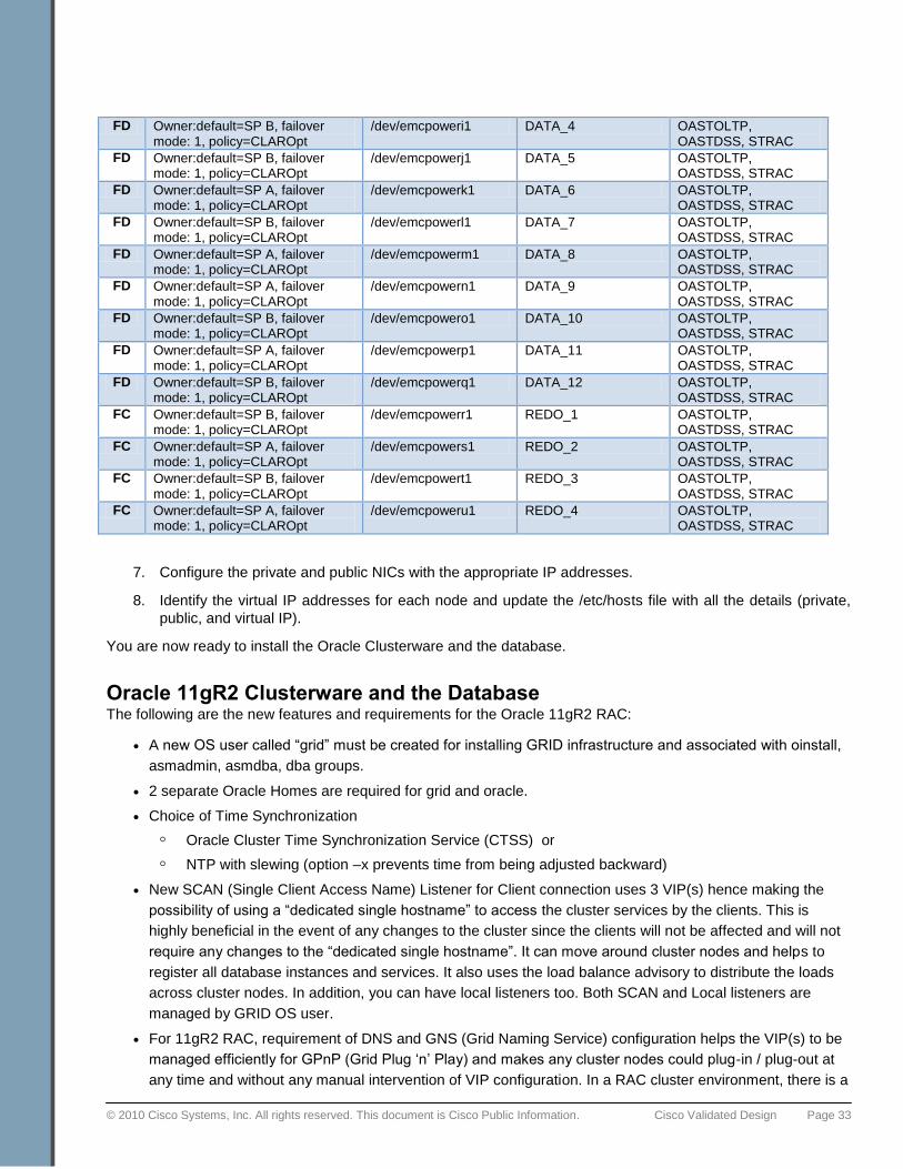
Table 9. LUNs for 8-node Oracle RAC Cluster
Disk Type
SP Path Details of EMC® CLARiiON
Mapped PowerPath Devices
Oracle ASM DG Label Purpose
FC Owner:default=SP A, failover mode: 1, policy=CLAROpt
/dev/emcpowera1 CLUSTERGRID_VOL1 ASM (Voting Disk, OCR)
FC Owner:default=SP B, failover mode: 1, policy=CLAROpt
/dev/emcpowerb1 CLUSTERGRID_VOL2 ASM (Voting Disk, OCR)
FC Owner:default=SP B, failover mode: 1, policy=CLAROpt
/dev/emcpowerc1 CLUSTERGRID_VOL3 ASM (Voting Disk, OCR)
FC Owner:default=SP A, failover mode: 1, policy=CLAROpt
/dev/emcpowerd1 CLUSTERGRID_VOL4 ASM (Voting Disk, OCR)
FC Owner:default=SP B, failover mode: 1, policy=CLAROpt
/dev/emcpowere1 CLUSTERGRID_VOL5 ASM (Voting Disk, OCR)
FD Owner:default=SP A, failover mode: 1, policy=CLAROpt
/dev/emcpowerf1 DATA_1 OASTOLTP, OASTDSS, STRAC
FD Owner:default=SP B, failover mode: 1, policy=CLAROpt
/dev/emcpowerg1 DATA_2 OASTOLTP, OASTDSS, STRAC
FD Owner:default=SP A, failover mode: 1, policy=CLAROpt
/dev/emcpowerh1 DATA_3 OASTOLTP, OASTDSS, STRAC
© 2010 Cisco Systems, Inc. All rights reserved. This document is Cisco Public Information. Cisco Validated Design Page 33
FD Owner:default=SP B, failover mode: 1, policy=CLAROpt
/dev/emcpoweri1 DATA_4 OASTOLTP, OASTDSS, STRAC
FD Owner:default=SP B, failover mode: 1, policy=CLAROpt
/dev/emcpowerj1 DATA_5 OASTOLTP, OASTDSS, STRAC
FD Owner:default=SP A, failover mode: 1, policy=CLAROpt
/dev/emcpowerk1 DATA_6 OASTOLTP, OASTDSS, STRAC
FD Owner:default=SP B, failover mode: 1, policy=CLAROpt
/dev/emcpowerl1 DATA_7 OASTOLTP, OASTDSS, STRAC
FD Owner:default=SP A, failover mode: 1, policy=CLAROpt
/dev/emcpowerm1 DATA_8 OASTOLTP, OASTDSS, STRAC
FD Owner:default=SP A, failover mode: 1, policy=CLAROpt
/dev/emcpowern1 DATA_9 OASTOLTP, OASTDSS, STRAC
FD Owner:default=SP B, failover mode: 1, policy=CLAROpt
/dev/emcpowero1 DATA_10 OASTOLTP, OASTDSS, STRAC
FD Owner:default=SP A, failover mode: 1, policy=CLAROpt
/dev/emcpowerp1 DATA_11 OASTOLTP, OASTDSS, STRAC
FD Owner:default=SP B, failover mode: 1, policy=CLAROpt
/dev/emcpowerq1 DATA_12 OASTOLTP, OASTDSS, STRAC
FC Owner:default=SP B, failover mode: 1, policy=CLAROpt
/dev/emcpowerr1 REDO_1 OASTOLTP, OASTDSS, STRAC
FC Owner:default=SP A, failover mode: 1, policy=CLAROpt
/dev/emcpowers1 REDO_2 OASTOLTP, OASTDSS, STRAC
FC Owner:default=SP B, failover mode: 1, policy=CLAROpt
/dev/emcpowert1 REDO_3 OASTOLTP, OASTDSS, STRAC
FC Owner:default=SP A, failover mode: 1, policy=CLAROpt
/dev/emcpoweru1 REDO_4 OASTOLTP, OASTDSS, STRAC
7. Configure the private and public NICs with the appropriate IP addresses.
8. Identify the virtual IP addresses for each node and update the /etc/hosts file with all the details (private,
public, and virtual IP).
You are now ready to install the Oracle Clusterware and the database.
Oracle 11gR2 Clusterware and the Database The following are the new features and requirements for the Oracle 11gR2 RAC:
● A new OS user called ―grid‖ must be created for installing GRID infrastructure and associated with oinstall,
asmadmin, asmdba, dba groups.
● 2 separate Oracle Homes are required for grid and oracle.
● Choice of Time Synchronization
◦ Oracle Cluster Time Synchronization Service (CTSS) or
◦ NTP with slewing (option –x prevents time from being adjusted backward)
● New SCAN (Single Client Access Name) Listener for Client connection uses 3 VIP(s) hence making the
possibility of using a ―dedicated single hostname‖ to access the cluster services by the clients. This is
highly beneficial in the event of any changes to the cluster since the clients will not be affected and will not
require any changes to the ―dedicated single hostname‖. It can move around cluster nodes and helps to
register all database instances and services. It also uses the load balance advisory to distribute the loads
across cluster nodes. In addition, you can have local listeners too. Both SCAN and Local listeners are
managed by GRID OS user.
● For 11gR2 RAC, requirement of DNS and GNS (Grid Naming Service) configuration helps the VIP(s) to be
managed efficiently for GPnP (Grid Plug ‗n‘ Play) and makes any cluster nodes could plug-in / plug-out at
any time and without any manual intervention of VIP configuration. In a RAC cluster environment, there is a
© 2010 Cisco Systems, Inc. All rights reserved. This document is Cisco Public Information. Cisco Validated Design Page 34
high chance of nodes being added and removed dynamically as per certain customer requirements. In this
situation, the complete administration with ip address management and name resolution management is
done by the cluster itself using GNS. There is no need to do any manual work in updating connection
strings, configuring Virtual IP numbers etc. If you decide to use GNS, it is required that a GNS sub-domain
must be created and the DNS must be configured such that each request for this sub-domain will be
delegated to the GNS sub-domain for request handling. The GNS VIP address is the ip address of the
server that will host the GNS. You need to make sure that one GNS VIP is available for use. Single SCAN
hostname resolves to 3 VIPs and during installation, DNS resolution provides 3 VIPs which are used to
create 3 SCAN-VIP / Listener pairs scattered across the cluster.
● Policy-based cluster and Server Pool capacity management allows efficient allocation of resources to all
kinds of applications in the cluster. This way, the applications can be hosted on a shared infrastructure
while being isolated regarding their resource consumption via policies and therefore behave as if they were
deployed in dedicated system environments. These features can be summarized as following:
Database Policy Management:
◦ Allows defining resource requirements of workload.
◦ Oracle Clusterware allocates and reassigns capacity based on defined policies. This enables faster
resource failover and dynamic capacity assignment.
◦ Enough instances are started to support workload requirements
◦ Eliminates need to hard code a service to a specific instance or node.
Server Pool:
◦ Logical division of the cluster into pools of servers
◦ Managed by crsctl (applications), srvctl (Oracle)
◦ Defined by 3 attributes (min, max, importance) or a defined list of nodes.
● The following Metalink notes provide additional details about these new features:
◦ 1053147.1: Oracle 11gR2 Clusterware and Grid Home (What you need to know) details
◦ 887522.1 Oracle 11gR2 Grid Infrastructure SCAN Explained.
◦ 946452.1 11gR2 Grid Infrastructure GNS Explained
Installing Oracle Clusterware and the Database The next step is to install the Oracle Clusterware and database software. For more information about the Oracle
RAC installation, refer to the Oracle install documentation.
1. Download the Oracle Database 11g Release 2 (11.2.0.1.0) software.
2. Install Oracle Database 11g Release 2 Grid Infrastructure.
3. Install Oracle Database 11g Release 2 Database ―Software Only‖; do not create the database.
Database and Workload Configuration After the database software is installed, create the following two databases using DBCA for 8 node 11gR2 cluster
using Policy based Management:
● OLTP database – 2400 Users performing smaller and random transactions.
● DSS database – 160 Users with larger transactions
In addition, we also used a custom database (STRAC) with a focus to generate high amount of cache fusion
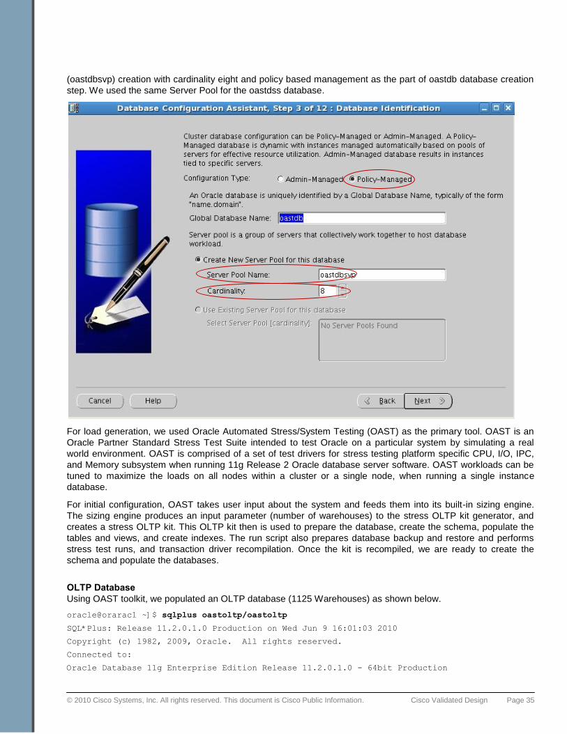
traffic. We will not go into step-by-step database creation but the screenshot below highlights the server pool
© 2010 Cisco Systems, Inc. All rights reserved. This document is Cisco Public Information. Cisco Validated Design Page 35
(oastdbsvp) creation with cardinality eight and policy based management as the part of oastdb database creation
step. We used the same Server Pool for the oastdss database.
For load generation, we used Oracle Automated Stress/System Testing (OAST) as the primary tool. OAST is an
Oracle Partner Standard Stress Test Suite intended to test Oracle on a particular system by simulating a real
world environment. OAST is comprised of a set of test drivers for stress testing platform specific CPU, I/O, IPC,
and Memory subsystem when running 11g Release 2 Oracle database server software. OAST workloads can be
tuned to maximize the loads on all nodes within a cluster or a single node, when running a single instance
database.
For initial configuration, OAST takes user input about the system and feeds them into its built-in sizing engine.
The sizing engine produces an input parameter (number of warehouses) to the stress OLTP kit generator, and
creates a stress OLTP kit. This OLTP kit then is used to prepare the database, create the schema, populate the
tables and views, and create indexes. The run script also prepares database backup and restore and performs
stress test runs, and transaction driver recompilation. Once the kit is recompiled, we are ready to create the
schema and populate the databases.
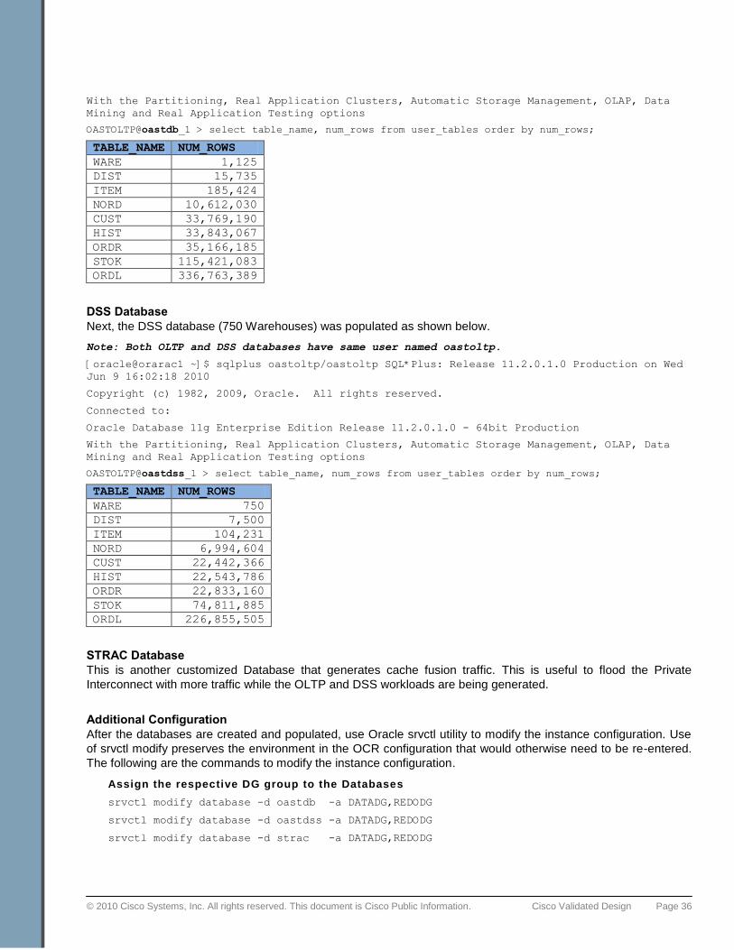
OLTP Database
Using OAST toolkit, we populated an OLTP database (1125 Warehouses) as shown below.
oracle@orarac1 ~]$ sqlplus oastoltp/oastoltp
SQL*Plus: Release 11.2.0.1.0 Production on Wed Jun 9 16:01:03 2010
Copyright (c) 1982, 2009, Oracle. All rights reserved.
Connected to:
Oracle Database 11g Enterprise Edition Release 11.2.0.1.0 - 64bit Production
© 2010 Cisco Systems, Inc. All rights reserved. This document is Cisco Public Information. Cisco Validated Design Page 36
With the Partitioning, Real Application Clusters, Automatic Storage Management, OLAP, Data
Mining and Real Application Testing options
OASTOLTP@oastdb_1 > select table_name, num_rows from user_tables order by num_rows;
TABLE_NAME NUM_ROWS
WARE 1,125
DIST 15,735
ITEM 185,424
NORD 10,612,030
CUST 33,769,190
HIST 33,843,067
ORDR 35,166,185
STOK 115,421,083
ORDL 336,763,389
DSS Database
Next, the DSS database (750 Warehouses) was populated as shown below.
Note: Both OLTP and DSS databases have same user named oastoltp.
[oracle@orarac1 ~]$ sqlplus oastoltp/oastoltp SQL*Plus: Release 11.2.0.1.0 Production on Wed
Jun 9 16:02:18 2010
Copyright (c) 1982, 2009, Oracle. All rights reserved.
Connected to:
Oracle Database 11g Enterprise Edition Release 11.2.0.1.0 - 64bit Production
With the Partitioning, Real Application Clusters, Automatic Storage Management, OLAP, Data
Mining and Real Application Testing options
OASTOLTP@oastdss_1 > select table_name, num_rows from user_tables order by num_rows;
TABLE_NAME NUM_ROWS
WARE 750
DIST 7,500
ITEM 104,231
NORD 6,994,604
CUST 22,442,366
HIST 22,543,786
ORDR 22,833,160
STOK 74,811,885
ORDL 226,855,505
STRAC Database
This is another customized Database that generates cache fusion traffic. This is useful to flood the Private
Interconnect with more traffic while the OLTP and DSS workloads are being generated.
Additional Configuration
After the databases are created and populated, use Oracle srvctl utility to modify the instance configuration. Use
of srvctl modify preserves the environment in the OCR configuration that would otherwise need to be re-entered.
The following are the commands to modify the instance configuration.
Assign the respective DG group to the Databases
srvctl modify database -d oastdb -a DATADG,REDODG
srvctl modify database -d oastdss -a DATADG,REDODG
srvctl modify database -d strac -a DATADG,REDODG
© 2010 Cisco Systems, Inc. All rights reserved. This document is Cisco Public Information. Cisco Validated Design Page 37
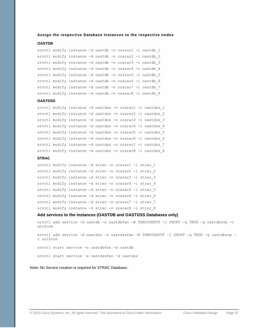
Assign the respective Database Instances to the respective nodes OASTDB
srvctl modify instance -d oastdb -n orarac1 -i oastdb_1
srvctl modify instance -d oastdb -n orarac2 -i oastdb_2
srvctl modify instance -d oastdb -n orarac3 -i oastdb_3
srvctl modify instance -d oastdb -n orarac4 -i oastdb_4
srvctl modify instance -d oastdb -n orarac5 -i oastdb_5
srvctl modify instance -d oastdb -n orarac6 -i oastdb_6
srvctl modify instance -d oastdb -n orarac7 -i oastdb_7
srvctl modify instance -d oastdb -n orarac8 -i oastdb_8
OASTDSS
srvctl modify instance -d oastdss -n orarac1 -i oastdss_1
srvctl modify instance -d oastdss -n orarac2 -i oastdss_2
srvctl modify instance -d oastdss -n orarac3 -i oastdss_3
srvctl modify instance -d oastdss -n orarac4 -i oastdss_4
srvctl modify instance -d oastdss -n orarac5 -i oastdss_5
srvctl modify instance -d oastdss -n orarac6 -i oastdss_6
srvctl modify instance -d oastdss -n orarac7 -i oastdss_7
srvctl modify instance -d oastdss -n orarac8 -i oastdss_8
STRAC
srvctl modify instance -d strac -n orarac1 -i strac_1
srvctl modify instance -d strac -n orarac2 -i strac_2
srvctl modify instance -d strac -n orarac3 -i strac_3
srvctl modify instance -d strac -n orarac4 -i strac_4
srvctl modify instance -d strac -n orarac5 -i strac_5
srvctl modify instance -d strac -n orarac6 -i strac_6
srvctl modify instance -d strac -n orarac7 -i strac_7
srvctl modify instance -d strac -n orarac8 -i strac_8
Add services to the instances (OASTDB and OASTDSS Databases only)
srvctl add service -d oastdb -s oastdbfan -B THROUGHPUT -j SHORT -q TRUE -g oastdbsvp -c
uniform
srvctl add service -d oastdss -s oastdssfan -B THROUGHPUT -j SHORT -q TRUE -g oastdbsvp -
c uniform
srvctl start service -s oastdbfan -d oastdb
srvctl start service -s oastdssfan -d oastdss
Note: No Service creation is required for STRAC Database.
© 2010 Cisco Systems, Inc. All rights reserved. This document is Cisco Public Information. Cisco Validated Design Page 38
Testing Workload Performance After the databases are created and configured, you need to perform the stress tests. The stress test criteria is
listed below.
● Normal CPU utilization should be close to 100% and run queues higher than 30 should be achieved.
External tools such as CPU busy scripts can be used as a supplemental tool to maximize CPU.
● Memory utilization greater than 90 percent should be sustained and spikes in the workload should cause
memory utilization going over 100% to force, memory paging, swapping and memory defragmentation.
● Disk IO stress should be high, but not as high that it would limit the CPU utilization on the system. If not
enough disk stress can be achieved by just running the database workloads, artificial stress should be
added to the system using disk stress tools.
● Network IO stress should be high, but not as high that it would limit the CPU utilization on the system. If not
enough network stress can be achieved by just running the database workloads, artificial stress should be
added to the system using network stress tools.
After the appropriate baseline is established for the above stress level criteria, the load must be run for 24 hours.
We established the baseline with:
● Database workloads:
◦ OLTP workload with 2400 users (Approx 300 users/node)
◦ DSS workload with 160 users (Approx. 20 users/node)
◦ STRAC cache fusion workload scripts were run to flood private interconnect
● CPU stress Program: This program runs high CPU cycle oriented functions and saturates CPU usage. This
program runs on all 8 nodes.
● IPERF iperf is a commonly used network testing tool that can create TCP and UDP data streams and
measure the throughput of a network that is carrying them. This program was run on all 8 nodes.
The following are the general observations from the stress tests followed by workload specific details.
Observations:
● Achieved very consistent resource utilization around 90 percent on all 8 nodes.
● No saturation levels or resource stalling on any subsystems (CPU, disk, I/O, or networking)
● Sustained FCoE-based I/O ranging between 2.0 GBytes/Sec and 2.4 GBytes per second.
● No performance degradation over time or occurrences of bottlenecks or wait times.
● Excellent I/O service times from the EMC CLARiiON storage.
This consistent workload performance without any significant tuning can be attributed to:
● The simplified, excellent architectural design of the Cisco Unified Computing System based on a 10-Gbps
unified fabric.
● The pairing of the Cisco Unified Computing System with EMC CLARiiON storage with high-performance
Flash drives.
Note: This is a testing, not a performance benchmarking, exercise. The numbers presented here should not be used for
comparison purposes. The intent here is to look at the Cisco Unified Computing System supporting a sustained load over a
long time period. Note that no tuning was performed and the lack of resource saturation without external load generation tools
indicate that significant headroom is available to support greater performance than that shown in this exercise.

© 2010 Cisco Systems, Inc. All rights reserved. This document is Cisco Public Information. Cisco Validated Design Page 39
OLTP Workload
The figure below shows a three hour sample of the OLTP workload running with 2400 users during the stress test.
Figure 8. OLTP Transactions per Minute
For OLTP workload, we observed the transactions ranging between 1.5 Million to 2.5 Million.
DSS Workload
DSS workloads are generally sequential in nature and read intensive. For DSS workloads, it is common practice
to set the parallel queries and the degree of parallelism on heavily read tables. This practice was followed in the
test environment and achieved excellent performance, as indicated in the Tablespace and File IO Stats
information from the Oracle Automated Workload Repository (AWR) report (24-hour duration) shown in the tables
below.
Table 10. Oracle AWR Report Tablespace IO Stats Information for DSS
Tablespace Reads Av Reads/s
Av Rd(ms)
Av Blks/Rd
Writes Av Writes/s
Buffer Waits
Av Buf Wt(ms)
CUST_0 33,087,581 189 0.01 63.88 0 0 9 30.00
ORDL_0 22,915,549 131 0.00 39.30 0 0 20,720,091 39.93
As shown above, the CUST_0 and ORDL_0 tablespaces have combined 320 read operations per second. The
CUST_0 reads are approximately (64 Blocks * 8K * 189) 97 Mbytes/Sec. and ORDL_0 reads are (39 * 8K * 131)
41Mbytes/Sec. So, the total reads from these two tablespaces are about 137 Mbytes/sec. We observed similar IO
patterns across all 8 nodes. The table below highlights superb read response times that the Flash drives on the
CLARiiON are providing on the same tables.
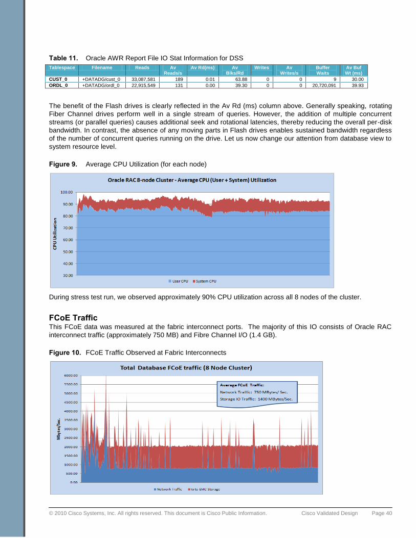
© 2010 Cisco Systems, Inc. All rights reserved. This document is Cisco Public Information. Cisco Validated Design Page 40
Table 11. Oracle AWR Report File IO Stat Information for DSS
Tablespace Filename Reads Av Reads/s
Av Rd(ms) Av Blks/Rd
Writes Av Writes/s
Buffer Waits
Av Buf Wt (ms)
CUST_0 +DATADG/cust_0 33,087,581 189 0.01 63.88 0 0 9 30.00
ORDL_0 +DATADG/ordl_0 22,915,549 131 0.00 39.30 0 0 20,720,091 39.93
The benefit of the Flash drives is clearly reflected in the Av Rd (ms) column above. Generally speaking, rotating
Fiber Channel drives perform well in a single stream of queries. However, the addition of multiple concurrent
streams (or parallel queries) causes additional seek and rotational latencies, thereby reducing the overall per-disk
bandwidth. In contrast, the absence of any moving parts in Flash drives enables sustained bandwidth regardless
of the number of concurrent queries running on the drive. Let us now change our attention from database view to
system resource level.
Figure 9. Average CPU Utilization (for each node)
During stress test run, we observed approximately 90% CPU utilization across all 8 nodes of the cluster.
FCoE Traffic This FCoE data was measured at the fabric interconnect ports. The majority of this IO consists of Oracle RAC
interconnect traffic (approximately 750 MB) and Fibre Channel I/O (1.4 GB).
Figure 10. FCoE Traffic Observed at Fabric Interconnects
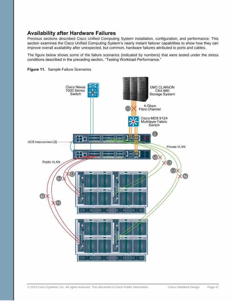
© 2010 Cisco Systems, Inc. All rights reserved. This document is Cisco Public Information. Cisco Validated Design Page 41
Availability after Hardware Failures Previous sections described Cisco Unified Computing System installation, configuration, and performance. This
section examines the Cisco Unified Computing System‘s nearly instant failover capabilities to show how they can
improve overall availability after unexpected, but common, hardware failures attributed to ports and cables.
The figure below shows some of the failure scenarios (indicated by numbers) that were tested under the stress
conditions described in the preceding section, ―Testing Workload Performance.‖
Figure 11. Sample Failure Scenarios
© 2010 Cisco Systems, Inc. All rights reserved. This document is Cisco Public Information. Cisco Validated Design Page 42
The table below summarizes the failure scenarios (each indicated by a number in Figure 10) and describes how
the Cisco Unified Computing System architecture sustains unexpected failures related to ports, links, and the
fabric interconnect (a rare occurrence).
Table 12. Failure Scenarios and the Cisco Unified Computing System Response
Failure Scenario (Figure 10)
Description Response
1 or 3 Single-link failure (public interface) Represents port failure; nodes should continue to work
2 or 4 All-links failure (public interface) Nodes should continue to work through other I/O module
5 or 7 Single-link failure (private interconnect) Represents port failure; nodes should continue to work
6 or 8 All-links failure (private interconnect) Nodes should continue to work through other I/O module
9 Storage path failure Single I/O path loss should have no effect; if all I/O paths fail, nodes should reboot
2 and 6 or 4 and 8
Failure of both I/O modules on a single chassis
All nodes in failed chassis should reboot; nodes in other chassis should continue to work
10 Fabric interconnect failure All nodes should continue to work through other fabric interconnect
Conclusion Designed using a new and innovative approach to improve data center infrastructure, the Cisco Unified
Computing System unites compute, network, storage access, and virtualization resources into a scalable,
modular architecture that is managed as a single system.
For the Cisco Unified Computing System, Cisco has partnered with Oracle because Oracle databases and
applications provide mission-critical software foundations for the majority of large enterprises worldwide. In
addition, the architecture and large memory capabilities of the Cisco Unified Computing System connected to the
industry-proven and scalable CLARiiON storage system enable customers to scale and manage Oracle database
environments in ways not previously possible.
Both database administrators and system administrators will benefit from the Cisco Unified Computing System
combination of superior architecture, outstanding performance, and unified fabric. They can achieve
demonstrated results by following the documented best practices for database installation, configuration, and
management outlined in this document.
The workload performance testing included a realistic mix of OLTP and DSS workloads, which generated a
sustained load on the eight-node Oracle RAC configuration for a period of 72 hours. This type of load far exceeds
the demands of typical database deployments.
Despite the strenuous workload, the following high-performance metrics were achieved:
● The quad-core Intel Xeon 5500 series processors barely reached 50 percent of their capacity, leaving
substantial headroom for additional load.
● The average 10 Gigabit Ethernet port utilization at the fabric interconnect was about 40 percent.
● The I/O demands generated by the load were supported very efficiently by the capabilities of the minimally
configured EMC CLARiiON storage array. The array featured a mix of Fibre Channel and Flash drives.
In summary, the Cisco Unified Computing System is a new computing model that uses integrated management
and combines a wire-once unified fabric with an industry-standard computing platform.

© 2010 Cisco Systems, Inc. All rights reserved. This document is Cisco Public Information. Cisco Validated Design Page 43
The platform:
● Optimizes database environments
● Reduces total overall cost of the data center
● Provides dynamic resource provisioning for increased business agility
The benefits of the Cisco Unified Computing System include:
● Reduced TCO: Enables up to 20 percent reduction in capital expenditures (CapEx) and up to 30 percent
reduction in operating expenses (OpEx)
● Improved IT productivity and business agility: Enables IT to provision applications in minutes instead of
days and shifts the focus from IT maintenance to IT innovation
● Increased scalability without added complexity: Is managed as a single system, whether the system has
one server or 320 servers with thousands of virtual machines
● Improved energy efficiency: Significantly reduces power and cooling costs
● Interoperability and investment protection: Provides assurance through infrastructure based on industry
standards
For More Information Please visit http://www.cisco.com/en/US/netsol/ns944/index.html#.
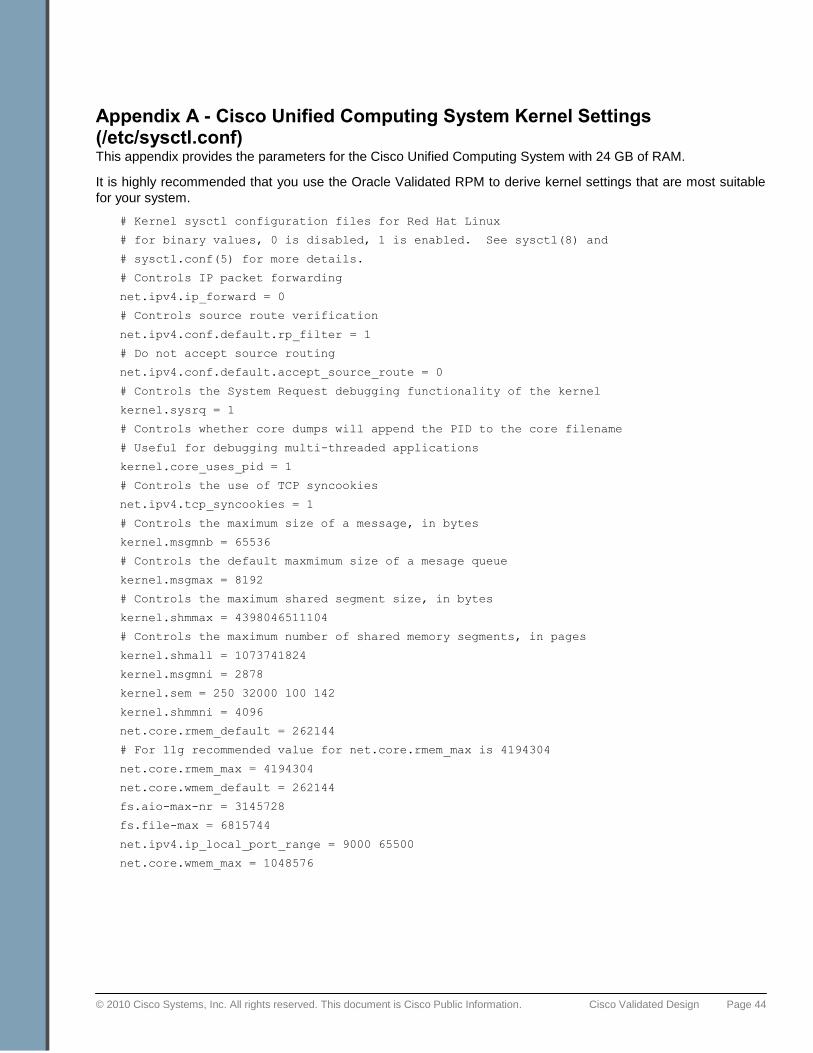
© 2010 Cisco Systems, Inc. All rights reserved. This document is Cisco Public Information. Cisco Validated Design Page 44
Appendix A - Cisco Unified Computing System Kernel Settings (/etc/sysctl.conf) This appendix provides the parameters for the Cisco Unified Computing System with 24 GB of RAM.
It is highly recommended that you use the Oracle Validated RPM to derive kernel settings that are most suitable
for your system.
# Kernel sysctl configuration files for Red Hat Linux
# for binary values, 0 is disabled, 1 is enabled. See sysctl(8) and
# sysctl.conf(5) for more details.
# Controls IP packet forwarding
net.ipv4.ip_forward = 0
# Controls source route verification
net.ipv4.conf.default.rp_filter = 1
# Do not accept source routing
net.ipv4.conf.default.accept_source_route = 0
# Controls the System Request debugging functionality of the kernel
kernel.sysrq = 1
# Controls whether core dumps will append the PID to the core filename
# Useful for debugging multi-threaded applications
kernel.core_uses_pid = 1
# Controls the use of TCP syncookies
net.ipv4.tcp_syncookies = 1
# Controls the maximum size of a message, in bytes
kernel.msgmnb = 65536
# Controls the default maxmimum size of a mesage queue
kernel.msgmax = 8192
# Controls the maximum shared segment size, in bytes
kernel.shmmax = 4398046511104
# Controls the maximum number of shared memory segments, in pages
kernel.shmall = 1073741824
kernel.msgmni = 2878
kernel.sem = 250 32000 100 142
kernel.shmmni = 4096
net.core.rmem_default = 262144
# For 11g recommended value for net.core.rmem_max is 4194304
net.core.rmem_max = 4194304
net.core.wmem_default = 262144
fs.aio-max-nr = 3145728
fs.file-max = 6815744
net.ipv4.ip_local_port_range = 9000 65500
net.core.wmem_max = 1048576
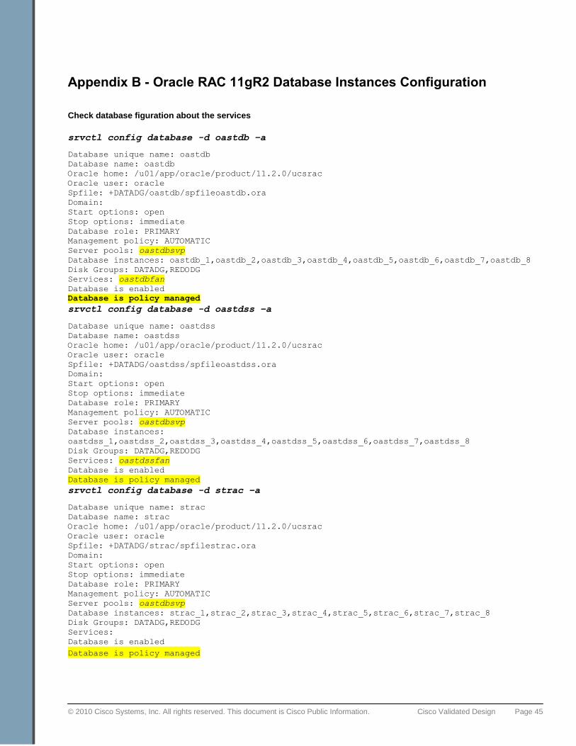
© 2010 Cisco Systems, Inc. All rights reserved. This document is Cisco Public Information. Cisco Validated Design Page 45
Appendix B - Oracle RAC 11gR2 Database Instances Configuration
Check database figuration about the services
srvctl config database -d oastdb –a
Database unique name: oastdb
Database name: oastdb
Oracle home: /u01/app/oracle/product/11.2.0/ucsrac
Oracle user: oracle
Spfile: +DATADG/oastdb/spfileoastdb.ora
Domain:
Start options: open
Stop options: immediate
Database role: PRIMARY
Management policy: AUTOMATIC
Server pools: oastdbsvp
Database instances: oastdb_1,oastdb_2,oastdb_3,oastdb_4,oastdb_5,oastdb_6,oastdb_7,oastdb_8
Disk Groups: DATADG,REDODG
Services: oastdbfan
Database is enabled
Database is policy managed
srvctl config database -d oastdss –a
Database unique name: oastdss
Database name: oastdss
Oracle home: /u01/app/oracle/product/11.2.0/ucsrac
Oracle user: oracle
Spfile: +DATADG/oastdss/spfileoastdss.ora
Domain:
Start options: open
Stop options: immediate
Database role: PRIMARY
Management policy: AUTOMATIC
Server pools: oastdbsvp
Database instances:
oastdss_1,oastdss_2,oastdss_3,oastdss_4,oastdss_5,oastdss_6,oastdss_7,oastdss_8
Disk Groups: DATADG,REDODG
Services: oastdssfan
Database is enabled
Database is policy managed
srvctl config database -d strac –a
Database unique name: strac
Database name: strac
Oracle home: /u01/app/oracle/product/11.2.0/ucsrac
Oracle user: oracle
Spfile: +DATADG/strac/spfilestrac.ora
Domain:
Start options: open
Stop options: immediate
Database role: PRIMARY
Management policy: AUTOMATIC
Server pools: oastdbsvp
Database instances: strac_1,strac_2,strac_3,strac_4,strac_5,strac_6,strac_7,strac_8
Disk Groups: DATADG,REDODG
Services:
Database is enabled
Database is policy managed
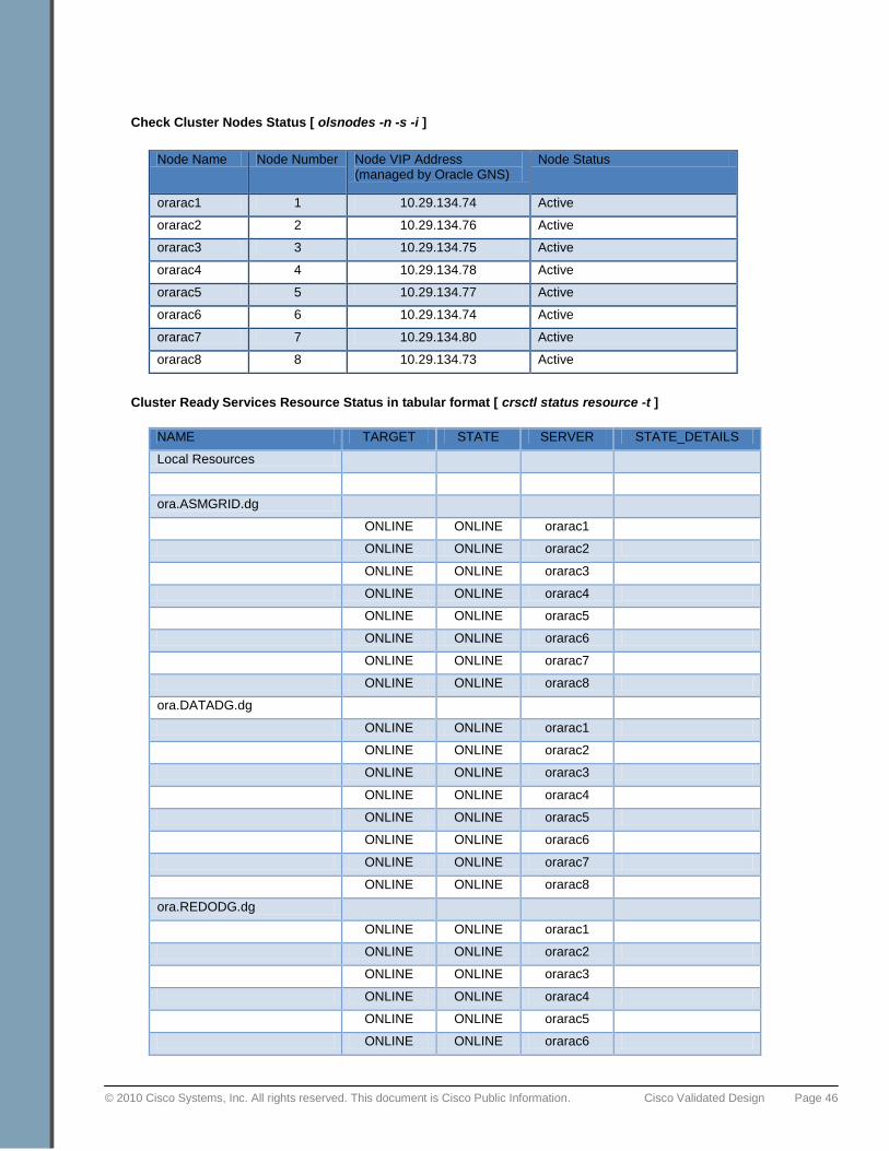
© 2010 Cisco Systems, Inc. All rights reserved. This document is Cisco Public Information. Cisco Validated Design Page 46
Check Cluster Nodes Status [ olsnodes -n -s -i ]
Cluster Ready Services Resource Status in tabular format [ crsctl status resource -t ]
NAME TARGET STATE SERVER STATE_DETAILS
Local Resources
ora.ASMGRID.dg
ONLINE ONLINE orarac1
ONLINE ONLINE orarac2
ONLINE ONLINE orarac3
ONLINE ONLINE orarac4
ONLINE ONLINE orarac5
ONLINE ONLINE orarac6
ONLINE ONLINE orarac7
ONLINE ONLINE orarac8
ora.DATADG.dg
ONLINE ONLINE orarac1
ONLINE ONLINE orarac2
ONLINE ONLINE orarac3
ONLINE ONLINE orarac4
ONLINE ONLINE orarac5
ONLINE ONLINE orarac6
ONLINE ONLINE orarac7
ONLINE ONLINE orarac8
ora.REDODG.dg
ONLINE ONLINE orarac1
ONLINE ONLINE orarac2
ONLINE ONLINE orarac3
ONLINE ONLINE orarac4
ONLINE ONLINE orarac5
ONLINE ONLINE orarac6
Node Name Node Number Node VIP Address (managed by Oracle GNS)
Node Status
orarac1 1 10.29.134.74 Active
orarac2 2 10.29.134.76 Active
orarac3 3 10.29.134.75 Active
orarac4 4 10.29.134.78 Active
orarac5 5 10.29.134.77 Active
orarac6 6 10.29.134.74 Active
orarac7 7 10.29.134.80 Active
orarac8 8 10.29.134.73 Active

© 2010 Cisco Systems, Inc. All rights reserved. This document is Cisco Public Information. Cisco Validated Design Page 47
ONLINE ONLINE orarac7
ONLINE ONLINE orarac8
ora.LISTENER.lsnr
ONLINE ONLINE orarac1
ONLINE ONLINE orarac2
ONLINE ONLINE orarac3
ONLINE ONLINE orarac4
ONLINE ONLINE orarac5
ONLINE ONLINE orarac6
ONLINE ONLINE orarac7
ONLINE ONLINE orarac8
ora.asm
ONLINE ONLINE orarac1 Started
ONLINE ONLINE orarac2 Started
ONLINE ONLINE orarac3 Started
ONLINE ONLINE orarac4 Started
ONLINE ONLINE orarac5 Started
ONLINE ONLINE orarac6 Started
ONLINE ONLINE orarac7 Started
ONLINE ONLINE orarac8 Started
ora.eons
ONLINE ONLINE orarac1
ONLINE ONLINE orarac2
ONLINE ONLINE orarac3
ONLINE ONLINE orarac4
ONLINE ONLINE orarac5
ONLINE ONLINE orarac6
ONLINE ONLINE orarac7
ONLINE ONLINE orarac8
ora.gsd
OFFLINE OFFLINE orarac1
OFFLINE OFFLINE orarac2
OFFLINE OFFLINE orarac3
OFFLINE OFFLINE orarac4
OFFLINE OFFLINE orarac5
OFFLINE OFFLINE orarac6
OFFLINE OFFLINE orarac7
OFFLINE OFFLINE orarac8
ora.net1.network
ONLINE ONLINE orarac1
ONLINE ONLINE orarac2
ONLINE ONLINE orarac3

© 2010 Cisco Systems, Inc. All rights reserved. This document is Cisco Public Information. Cisco Validated Design Page 48
ONLINE ONLINE orarac4
ONLINE ONLINE orarac5
ONLINE ONLINE orarac6
ONLINE ONLINE orarac7
ONLINE ONLINE orarac8
ora.ons
ONLINE ONLINE orarac1
ONLINE ONLINE orarac2
ONLINE ONLINE orarac3
ONLINE ONLINE orarac4
ONLINE ONLINE orarac5
ONLINE ONLINE orarac6
ONLINE ONLINE orarac7
ONLINE ONLINE orarac8
ora.registry.acfs
ONLINE ONLINE orarac1
ONLINE ONLINE orarac2
ONLINE ONLINE orarac3
ONLINE ONLINE orarac4
ONLINE ONLINE orarac5
ONLINE ONLINE orarac6
ONLINE ONLINE orarac7
ONLINE ONLINE orarac8
Cluster Resources
ora.LISTENER_SCAN1.lsnr
1 ONLINE ONLINE orarac7
ora.LISTENER_SCAN2.lsnr
1 ONLINE ONLINE orarac8
ora.LISTENER_SCAN3.lsnr
1 ONLINE ONLINE orarac2
ora.gns
1 ONLINE ONLINE orarac3
ora.gns.vip
1 ONLINE ONLINE orarac3
ora.oastdb.db
1 ONLINE ONLINE orarac1 Open
2 ONLINE ONLINE orarac7 Open
3 ONLINE ONLINE orarac3 Open
4 ONLINE ONLINE orarac4 Open
5 ONLINE ONLINE orarac5 Open

© 2010 Cisco Systems, Inc. All rights reserved. This document is Cisco Public Information. Cisco Validated Design Page 49
6 ONLINE ONLINE orarac6 Open
7 ONLINE ONLINE orarac2 Open
8 ONLINE ONLINE orarac8 Open
ora.oastdb.oastdbfan.svc
1 ONLINE ONLINE orarac1
2 ONLINE ONLINE orarac6
3 ONLINE ONLINE orarac3
4 ONLINE ONLINE orarac4
5 ONLINE ONLINE orarac2
6 ONLINE ONLINE orarac5
7 ONLINE ONLINE orarac7
8 ONLINE ONLINE orarac8
ora.oastdss.db
1 ONLINE ONLINE orarac1 Open
2 ONLINE ONLINE orarac6 Open
3 ONLINE ONLINE orarac3 Open
4 ONLINE ONLINE orarac4 Open
5 ONLINE ONLINE orarac2 Open
6 ONLINE ONLINE orarac5 Open
7 ONLINE ONLINE orarac7 Open
8 ONLINE ONLINE orarac8 Open
ora.oastdss.oastdssfan.svc
1 ONLINE ONLINE orarac1
2 ONLINE ONLINE orarac6
3 ONLINE ONLINE orarac2
4 ONLINE ONLINE orarac3
5 ONLINE ONLINE orarac5
6 ONLINE ONLINE orarac4
7 ONLINE ONLINE orarac7
8 ONLINE ONLINE orarac8
ora.oc4j
1 OFFLINE OFFLINE
ora.orarac1.vip
1 ONLINE ONLINE orarac1
ora.orarac2.vip
1 ONLINE ONLINE orarac2
ora.orarac3.vip
1 ONLINE ONLINE orarac3
ora.orarac4.vip
1 ONLINE ONLINE orarac4
ora.orarac5.vip
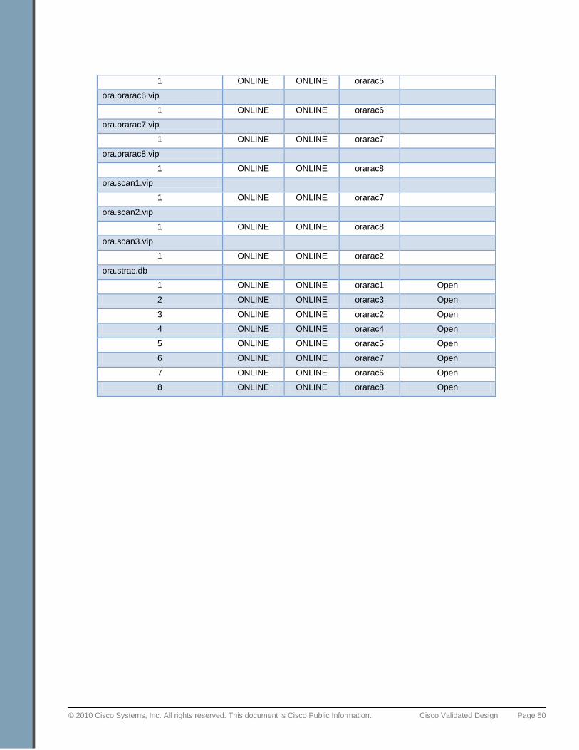
© 2010 Cisco Systems, Inc. All rights reserved. This document is Cisco Public Information. Cisco Validated Design Page 50
1 ONLINE ONLINE orarac5
ora.orarac6.vip
1 ONLINE ONLINE orarac6
ora.orarac7.vip
1 ONLINE ONLINE orarac7
ora.orarac8.vip
1 ONLINE ONLINE orarac8
ora.scan1.vip
1 ONLINE ONLINE orarac7
ora.scan2.vip
1 ONLINE ONLINE orarac8
ora.scan3.vip
1 ONLINE ONLINE orarac2
ora.strac.db
1 ONLINE ONLINE orarac1 Open
2 ONLINE ONLINE orarac3 Open
3 ONLINE ONLINE orarac2 Open
4 ONLINE ONLINE orarac4 Open
5 ONLINE ONLINE orarac5 Open
6 ONLINE ONLINE orarac7 Open
7 ONLINE ONLINE orarac6 Open
8 ONLINE ONLINE orarac8 Open

© 2010 Cisco Systems, Inc. All rights reserved. This document is Cisco Public Information. Cisco Validated Design Page 51
Appendix C - DNS and GNS Setup and Configuration If you would like to use Oracle GNS and it requires the DNS server, DHCP server to do the range of VIP(s) to be
published to the respective 8 Node(s) VIP(s), 3 SCAN VIP(s).
DNS Settings (/etc/named.conf)
options {
// DNS tables are located in the /var/named directory
directory "/var/named";
// Forward any unresolved requests to our ISP's name server
// (this is an example IP address only -- do not use!)
// forwarders {
// 10;
// };
/*
* If there is a firewall between you and nameservers you want
* to talk to, you might need to uncomment the query-source
* directive below. Previous versions of BIND always asked
* questions using port 53, but BIND 8.1 uses an unprivileged
* port by default.
*/
// query-source address * port 53;
allow-query { any; };
};
// Enable caching and load root server info
zone "named.root" {
type hint;
file "";
};
zone "0.0.127.in-addr.arpa" {
type master;
file "127_0_0.rev";
notify no;
};
zone "ucs.cisco.com" IN {
type master;
file "ucs_cisco_com.db";
};
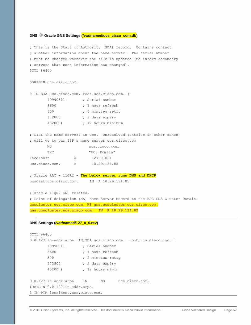
© 2010 Cisco Systems, Inc. All rights reserved. This document is Cisco Public Information. Cisco Validated Design Page 52
DNS Oracle GNS Settings (/var/named/ucs_cisco_com.db)
; This is the Start of Authority (SOA) record. Contains contact
; & other information about the name server. The serial number
; must be changed whenever the file is updated (to inform secondary
; servers that zone information has changed).
$TTL 86400
$ORIGIN ucs.cisco.com.
@ IN SOA ucs.cisco.com. root.ucs.cisco.com. (
19990811 ; Serial number
3600 ; 1 hour refresh
300 ; 5 minutes retry
172800 ; 2 days expiry
43200 ) ; 12 hours minimum
; List the name servers in use. Unresolved (entries in other zones)
; will go to our ISP's name server ucs.cisco.com
NS ucs.cisco.com.
TXT "UCS Domain"
localhost A 127.0.0.1
ucs.cisco.com. A 10.29.134.85
; Oracle RAC - 11GR2 - The below server runs DNS and DHCP
ucsoast.ucs.cisco.com. IN A 10.29.134.85
; Oracle 11gR2 GNS related.
; Point of delegation (NS) Name Server Record to the RAC GNS Cluster Domain.
ucscluster.ucs.cisco.com. NS gns.ucscluster.ucs.cisco.com.
gns.ucscluster.ucs.cisco.com. IN A 10.29.134.82
DNS Settings (/var/named/127_0_0.rev)
$TTL 86400
0.0.127.in-addr.arpa. IN SOA ucs.cisco.com. root.ucs.cisco.com. (
19990811 ; Serial number
3600 ; 1 hour refresh
300 ; 5 minutes retry
172800 ; 2 days expiry
43200 ) ; 12 hours minim
0.0.127.in-addr.arpa. IN NS ucs.cisco.com.
$ORIGIN 0.0.127.in-addr.arpa.
1 IN PTR localhost.ucs.cisco.com.
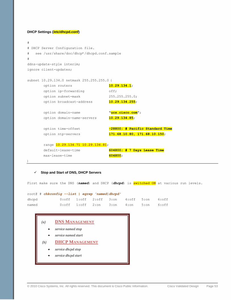
© 2010 Cisco Systems, Inc. All rights reserved. This document is Cisco Public Information. Cisco Validated Design Page 53
DHCP Settings (/etc/dhcpd.conf)
#
# DHCP Server Configuration file.
# see /usr/share/doc/dhcp*/dhcpd.conf.sample
#
ddns-update-style interim;
ignore client-updates;
subnet 10.29.134.0 netmask 255.255.255.0 {
option routers 10.29.134.1;
option ip-forwarding off;
option subnet-mask 255.255.255.0;
option broadcast-address 10.29.134.255;
option domain-name "ucs.cisco.com";
option domain-name-servers 10.29.134.85;
option time-offset -28800; # Pacific Standard Time
option ntp-servers 171.68.10.80, 171.68.10.150;
range 10.29.134.71 10.29.134.81;
default-lease-time 604800; # 7 Days Lease Time
max-lease-time 604800;
}
Stop and Start of DNS, DHCP Servers
First make sure the DNS (named) and DHCP (dhcpd) is switched ON at various run levels.
root@ # chkconfig --list | egrep 'named|dhcpd'
dhcpd 0:off 1:off 2:off 3:on 4:off 5:on 6:off
named 0:off 1:off 2:on 3:on 4:on 5:on 6:off
(a) DNS MANAGEMENT
service named stop
service named start
(b) DHCP MANAGEMENT
service dhcpd stop
service dhcpd start
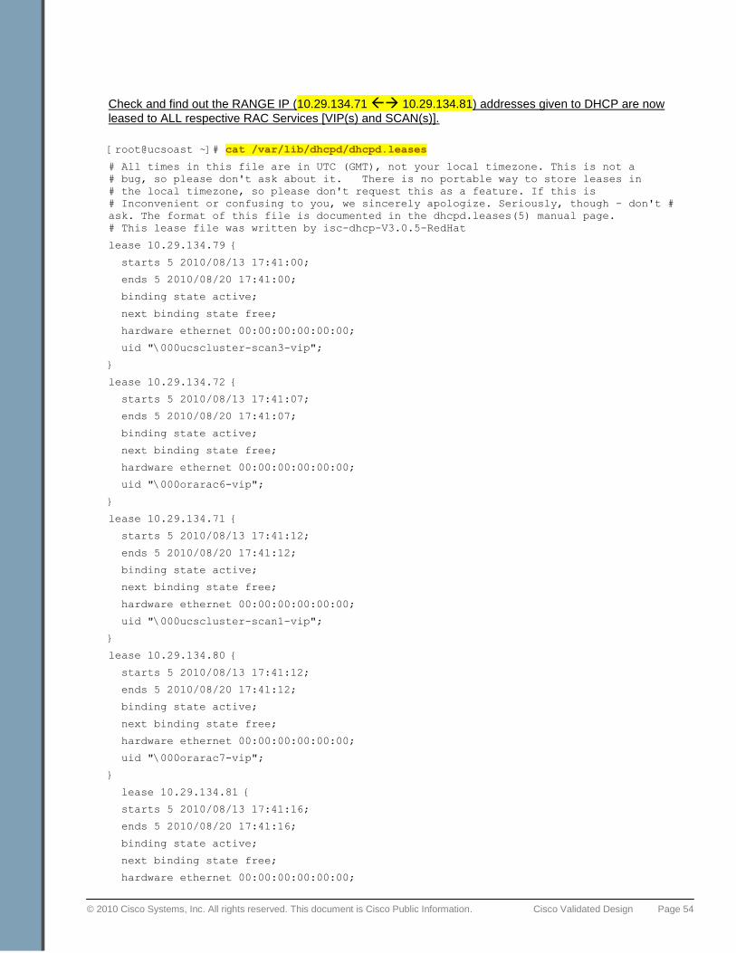
© 2010 Cisco Systems, Inc. All rights reserved. This document is Cisco Public Information. Cisco Validated Design Page 54
Check and find out the RANGE IP (10.29.134.71 10.29.134.81) addresses given to DHCP are now
leased to ALL respective RAC Services [VIP(s) and SCAN(s)].
[root@ucsoast ~]# cat /var/lib/dhcpd/dhcpd.leases
# All times in this file are in UTC (GMT), not your local timezone. This is not a
# bug, so please don't ask about it. There is no portable way to store leases in
# the local timezone, so please don't request this as a feature. If this is
# Inconvenient or confusing to you, we sincerely apologize. Seriously, though - don't #
ask. The format of this file is documented in the dhcpd.leases(5) manual page.
# This lease file was written by isc-dhcp-V3.0.5-RedHat
lease 10.29.134.79 {
starts 5 2010/08/13 17:41:00;
ends 5 2010/08/20 17:41:00;
binding state active;
next binding state free;
hardware ethernet 00:00:00:00:00:00;
uid "\000ucscluster-scan3-vip";
}
lease 10.29.134.72 {
starts 5 2010/08/13 17:41:07;
ends 5 2010/08/20 17:41:07;
binding state active;
next binding state free;
hardware ethernet 00:00:00:00:00:00;
uid "\000orarac6-vip";
}
lease 10.29.134.71 {
starts 5 2010/08/13 17:41:12;
ends 5 2010/08/20 17:41:12;
binding state active;
next binding state free;
hardware ethernet 00:00:00:00:00:00;
uid "\000ucscluster-scan1-vip";
}
lease 10.29.134.80 {
starts 5 2010/08/13 17:41:12;
ends 5 2010/08/20 17:41:12;
binding state active;
next binding state free;
hardware ethernet 00:00:00:00:00:00;
uid "\000orarac7-vip";
}
lease 10.29.134.81 {
starts 5 2010/08/13 17:41:16;
ends 5 2010/08/20 17:41:16;
binding state active;
next binding state free;
hardware ethernet 00:00:00:00:00:00;
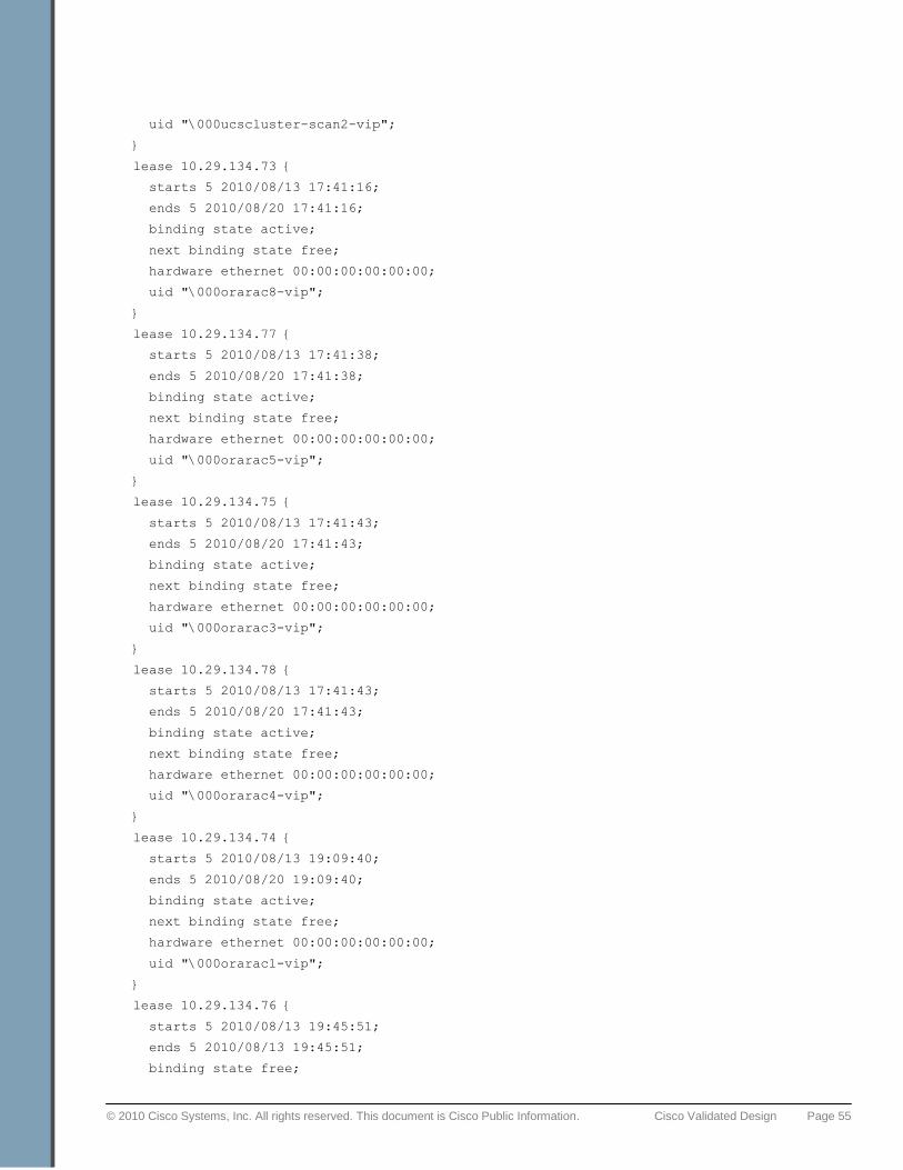
© 2010 Cisco Systems, Inc. All rights reserved. This document is Cisco Public Information. Cisco Validated Design Page 55
uid "\000ucscluster-scan2-vip";
}
lease 10.29.134.73 {
starts 5 2010/08/13 17:41:16;
ends 5 2010/08/20 17:41:16;
binding state active;
next binding state free;
hardware ethernet 00:00:00:00:00:00;
uid "\000orarac8-vip";
}
lease 10.29.134.77 {
starts 5 2010/08/13 17:41:38;
ends 5 2010/08/20 17:41:38;
binding state active;
next binding state free;
hardware ethernet 00:00:00:00:00:00;
uid "\000orarac5-vip";
}
lease 10.29.134.75 {
starts 5 2010/08/13 17:41:43;
ends 5 2010/08/20 17:41:43;
binding state active;
next binding state free;
hardware ethernet 00:00:00:00:00:00;
uid "\000orarac3-vip";
}
lease 10.29.134.78 {
starts 5 2010/08/13 17:41:43;
ends 5 2010/08/20 17:41:43;
binding state active;
next binding state free;
hardware ethernet 00:00:00:00:00:00;
uid "\000orarac4-vip";
}
lease 10.29.134.74 {
starts 5 2010/08/13 19:09:40;
ends 5 2010/08/20 19:09:40;
binding state active;
next binding state free;
hardware ethernet 00:00:00:00:00:00;
uid "\000orarac1-vip";
}
lease 10.29.134.76 {
starts 5 2010/08/13 19:45:51;
ends 5 2010/08/13 19:45:51;
binding state free;

© 2010 Cisco Systems, Inc. All rights reserved. This document is Cisco Public Information. Cisco Validated Design Page 56
hardware ethernet 00:00:00:00:00:00;
uid "\000orarac2-vip";
}
© 2010 Cisco Systems, Inc. All rights reserved. This document is Cisco Public Information. Cisco Validated Design Page 57
About Cisco Validated Design (CVD) Program
The CVD program consists of systems and solutions designed, tested, and documented to facilitate faster, more
reliable, and more predictable customer deployments. For more information visit www.cisco.com/go/designzone.
ALL DESIGNS, SPECIFICATIONS, STATEMENTS, INFORMATION, AND RECOMMENDATIONS
(COLLECTIVELY, "DESIGNS") IN THIS MANUAL ARE PRESENTED "AS IS," WITH ALL FAULTS. CISCO AND
ITS SUPPLIERS DISCLAIM ALL WARRANTIES, INCLUDING, WITHOUT LIMITATION, THE WARRANTY OF
MERCHANTABILITY, FITNESS FOR A PARTICULAR PURPOSE AND NONINFRINGEMENT OR ARISING
FROM A COURSE OF DEALING, USAGE, OR TRADE PRACTICE. IN NO EVENT SHALL CISCO OR ITS
SUPPLIERS BE LIABLE FOR ANY INDIRECT, SPECIAL, CONSEQUENTIAL, OR INCIDENTAL DAMAGES,
INCLUDING, WITHOUT LIMITATION, LOST PROFITS OR LOSS OR DAMAGE TO DATA ARISING OUT OF
THE USE OR INABILITY TO USE THE DESIGNS, EVEN IF CISCO OR ITS SUPPLIERS HAVE BEEN ADVISED
OF THE POSSIBILITY OF SUCH DAMAGES.
THE DESIGNS ARE SUBJECT TO CHANGE WITHOUT NOTICE. USERS ARE SOLELY RESPONSIBLE FOR
THEIR APPLICATION OF THE DESIGNS. THE DESIGNS DO NOT CONSTITUTE THE TECHNICAL OR
OTHER PROFESSIONAL ADVICE OF CISCO, ITS SUPPLIERS OR PARTNERS. USERS SHOULD CONSULT
THEIR OWN TECHNICAL ADVISORS BEFORE IMPLEMENTING THE DESIGNS. RESULTS MAY VARY
DEPENDING ON FACTORS NOT TESTED BY CISCO.
CCDE, CCENT, Cisco Eos, Cisco Lumin, Cisco Nexus, Cisco StadiumVision, Cisco TelePresence, Cisco WebEx,
the Cisco logo, DCE, and Welcome to the Human Network are trademarks; Changing the Way We Work, Live,
Play, and Learn and Cisco Store are service marks; and Access Registrar, Aironet, AsyncOS, Bringing the
Meeting To You, Catalyst, CCDA, CCDP, CCIE, CCIP, CCNA, CCNP, CCSP, CCVP, Cisco, the Cisco Certified
Internetwork Expert logo, Cisco IOS, Cisco Press, Cisco Systems, Cisco Systems Capital, the Cisco Systems
logo, Cisco Unity, Collaboration Without Limitation, EtherFast, EtherSwitch, Event Center, Fast Step, Follow Me
Browsing, FormShare, GigaDrive, HomeLink, Internet Quotient, IOS, iPhone, iQuick Study, IronPort, the IronPort
logo, LightStream, Linksys, MediaTone, MeetingPlace, MeetingPlace Chime Sound, MGX, Networkers,
Networking Academy, Network Registrar, PCNow, PIX, PowerPanels, ProConnect, ScriptShare, SenderBase,
SMARTnet, Spectrum Expert, StackWise, The Fastest Way to Increase Your Internet Quotient, TransPath,
WebEx, and the WebEx logo are registered trademarks of Cisco Systems, Inc. and/or its affiliates in the United
States and certain other countries.
All other trademarks mentioned in this document or website are the property of their respective owners. The use
of the word partner does not imply a partnership relationship between Cisco and any other company. (0809R)
© 2010 Cisco Systems, Inc. All rights reserved.
© 2010 Cisco Systems, Inc. All rights reserved. This document is Cisco Public Information. Cisco Validated Design Page 58
Cisco Systems, Inc.
170 West Tasman Drive
San Jose, CA 95134-1706
USA
www.cisco.com
Tel: 408 526-4000
800 553-NETS (6387)
Fax: 408 527-0883
Oracle Corporation
500 Oracle Parkway
Redwood Shores, CA 94065
USA
www.oracle.com
General Inquiries: 1.800.ORACLE1
International: 1.650.506.7000
© 2010 Cisco Systems, Inc. and/or its affiliated entities. All rights reserved. Cisco and the Cisco Logo are trademarks of Cisco Systems,
Inc. and/or its affiliates in the U.S. and other countries. A listing of Cisco's trademarks can be found at www.cisco.com/go/trademarks.
Third-party trademarks mentioned are the property of their respective owners. The use of the word partner does not imply a partnership
relationship between Cisco and any other company. (1005R)
Oracle, JD Edwards, PeopleSoft, and Siebel are registered trademarks of Oracle Corporation and/or its affiliates. Other names may be
trademarks of their respective owners.
Document number: UCS-TR100018