Embed Size (px)
Citation preview
DEPLOYMENT GUIDE
DEPLOYING F5 AUTOMATED NETWORK PROVISIONING FOR VMWARE INFRASTRUCTURE
Version: 1.0

Deploying F5 Automated Network Provisioning for VMware Infrastructure
Both VMware Infrastructure and the F5 BIG-IP system offer rich Application Programming Interfaces (APIs) that allow administrators to programmatically gather information or take actions through a variety of client libraries and languages. Additionally, VMware Infrastructure and ESX Server include the ability to take actions according to specific trigger events specific to a virtual machine or host.
Taken together, the combination of these capabilities provides a flexible infrastructure by which VMware Infrastructure and the F5 BIG-IP system can interact effectively to automatically scale applications as demand increases. The benefits of such a system include:
• Reduced server infrastructure usage during low volume times
• Reduced power and cooling costs
• Almost immediate response to changes in application traffic volumes
• Reduced administration effort to manage the virtual infrastructure
• Reduced risk of error during network configuration changes.
This guide outlines a simple architecture which demonstrates such a deployment. Your actual virtual machine and BIG-IP interactive provisioning will be highly application and infrastructure-specific. Rather than providing a rigid deployment topology and strategy, we show the basic functionality and give guidance for you to customize the suggestions according to your own specific needs.
Note
Throughout this document, the terms virtual machine and guest are used interchangeably to indicate virtualized operating systems running on VMware’s ESX virtualization platform. The term virtual server is used exclusively to indicate an object on F5's BIG-IP platform.
For information on the F5 Management Plug-In™ for VMware vSphere, see www.f5.com/pdf/deployment-guides/f5-management-plug-in-vsphere-dg.pdf
For additional resources on F5 and VMware, see the VMware forum on DevCentral.
This deployment guide is broken up into the following sections:
• Example 1: BIG-IP Local Traffic Manager and VMware Virtual Center, on page 3
• Example 2: F5 BIG-IP Global Traffic Manager and VMWare Virtual Center, on page 13
1
Deploying F5 Automated Network Provisioning for VMware Infrastructure
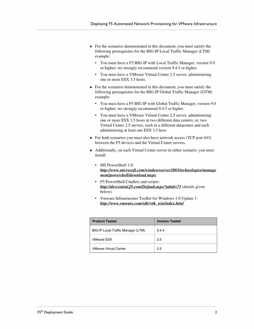
◆ For the scenarios demonstrated in this document, you must satisfy the following prerequisites for the BIG-IP Local Traffic Manager (LTM) example:
• You must have a F5 BIG-IP with Local Traffic Manager, version 9.0 or higher; we strongly recommend version 9.4.5 or higher.
• You must have a VMware Virtual Center 2.5 server, administering one or more ESX 3.5 hosts.
◆ For the scenarios demonstrated in this document, you must satisfy the following prerequisites for the BIG-IP Global Traffic Manager (GTM) example:
• You must have a F5 BIG-IP with Global Traffic Manager, version 9.0 or higher; we strongly recommend 9.4.5 or higher.
• You must have a VMware Virtual Center 2.5 server, administering one or more ESX 3.5 hosts in two different data centers; or, two Virtual Center 2.5 servers, each in a different datacenter and each administering at least one ESX 3.5 host.
◆ For both scenarios you must also have network access (TCP port 443) between the F5 devices and the Virtual Center servers.
◆ Additionally, on each Virtual Center server in either scenario, you must install:
• MS PowerShell 1.0: http://www.microsoft.com/windowsserver2003/technologies/management/powershell/download.mspx
• F5 PowerShell Cmdlets and scripts: http://devcentral.f5.com/Default.aspx?tabid=71 (details given below)
• Vmware Infrastructure Toolkit for Windows 1.0 Update 1: http://www.vmware.com/sdk/vitk_win/index.html
Product Tested Version Tested
BIG-IP Local Traffic Manager (LTM) 9.4.4
VMware ESX 3.5
VMware Virtual Center 2.5
F5® Deployment Guide 2

Example 1: BIG-IP Local Traffic Manager and VMware Virtual Center
Virtualization allows the rapid addition of application resources. For instance, if a pool of web servers reaches a pre-set threshold for RAM usage, Virtual Center can take action by starting another virtual machine instance of the web server on another host.
Without the ability to direct traffic to the new virtual machine-based application server, adding that instance by itself does not allow your environment to process additional traffic. By using the BIG-IP LTM to direct appropriate levels of traffic to the new virtual machine, at a time the virtual machine is able to correctly accept and process traffic, you are able to effectively scale as needed.
Although you could pre-configure BIG-IP LTM pools to include all possible members (i.e. IP address and port combinations) for potential but not-yet-activated virtual machines, you may wish to have iControl scripts do that automatically in response to Virtual Center events.
Goals and TopologyIn this example, we show the following scenario and resulting actions:
1. A VMware Infrastructure-hosted virtual machine running a web server (that is accessed through a BIG-IP LTM) reaches a pre-determined CPU usage threshold.
2. VMware Infrastructure brings a pre-configured virtual machine hosting another instance of the web server out of Suspended status.
3. VMware Infrastructure launches a PowerShell script that informs the LTM of the existence of the new virtual machine, and adds that VM as a member of the appropriate LTM pool.
4. Once the VM is online and available, the LTM directs traffic to the new virtual machine, according to pre-defined load-balancing rules.
The basic topology of such a deployment might look like Figure 1 on the following page.
3

Deploying F5 Automated Network Provisioning for VMware Infrastructure
Figure 1 Logical configuration example
Summary of StepsThis document will provide details, or links to external resources required to complete the following steps:
• Creating the web server virtual machine guests
• Creating the BIG-IP LTM configuration objects
• Installing Microsoft PowerShell on your Virtual Center Server
• Installing VMware VI Toolkit for Windows
• Creating a VI Toolkit Script to Power On Virtual Machines
• Installing the F5 iControl PowerShell Snapin
• Configuring the Alarm and Trigger Event
Firewalls
Internet
BIG-IP Local Traffic Manager
ESX Host
Clients
VM: web2(suspended)
VM: web1
Virtual Center
F5® Deployment Guide 4

Creating the web server virtual machine guestsIn this section, we create the web server virtual machine guests. For specific instructions on how to create or configure VMware objects, see the VMware documentation.
1. Using your Virtual Center server, create two resource pools on your ESX cluster. Name the pools ActiveWebServers and StandbyWebServers, respectively. You may keep default configuration settings for the pools or adjust them as appropriate for your environment.
2. Create two virtual machines that each run a web server on port 80. Exact procedures vary according to the operating system and web server software. Alternately, you can download a pre-configured virtual appliance from the VMWare Virtual Appliance Marketplace at http://vmware.com/appliances/directory/cat/53. In our example, we name the virtual machines web1 and web2 using the Virtual Infrastructure Client interface.
Each web server should be configured to have a different IP address. Each IP address must be accessible from your F5 BIG-IP LTM.
3. Place one of the web server virtual machines (in our case, web1) in the ActiveWebServers resource group and make sure it is running. Place the other virtual machine (web2) in StandbyWebServers and then Suspend that guest.
Creating the BIG-IP LTM configuration objectsIn this section, we create the BIG-IP LTM configuration objects.
Note
Exact procedures will vary according to the network configuration you are using and any specific settings required by your choice of web server software. The majority of settings in that guide will be identical for any choice of web servers.
Creating a nodeThe first step is to create a node for the virtual machine on the BIG-IP LTM system.
To create a node
1. On the Main tab, expand Local Traffic, and then click Nodes.The Node screen opens.
2. In the upper right portion of the screen, click the Create button. The New Node screen opens.
5

Deploying F5 Automated Network Provisioning for VMware Infrastructure
3. In the Address box, type the IP address of the web server in the ActiveWebServers resource pool.
4. In the Name box, type a name for the node. In our example, we type web1 to correspond with the name of the virtual machine that it represents.
5. Click the Finished button.
Figure 2 Creating the node
Creating the poolThe next task is to create a pool containing the node you just created.
To create the pool
1. On the Main tab, expand Local Traffic, and then click Pools.In the upper right portion of the screen, click the Create button. The New Pool screen opens.
2. In the Name box, type a name for your pool. In our example, we use WebServers.
3. From the Load Balancing Method list, select Least Connections (member).
4. In the New Members section, click Node List, and then select the node you created in the preceding procedure. In our example, we select 192.168.21.110.
5. In the Service Port box, type the appropriate port.
6. Click the Add button to add the member to the list.
7. Click the Finished button (see Figure 3).
F5® Deployment Guide 6

Figure 3 Creating the Pool
Creating the virtual serverThe final step in this section is to create a virtual server.
To create a virtual server
1. On the Main tab, expand Local Traffic, and then click Virtual Servers. The Virtual Servers screen opens.
2. In the upper right portion of the screen, click the Create button. The New Virtual Server screen opens.
3. In the Name box, type a name for this virtual server. In our example, we type MyHTTPVirtual.
4. In the Address box, type the IP address of this virtual server. In our example, we use 10.133.39.51.
5. In the Service Port box, type 80, or select HTTP from the list.
6. In the Resources section, from the HTTP profile list, select HTTP. You can optionally create a new HTTP profile before performing this step if you want to configure specific properties.
7

Deploying F5 Automated Network Provisioning for VMware Infrastructure
7. In the Resources section, from the Default Pool list, select the pool you created in the Creating the pool section. In our example, we select WebServers.
8. Click the Finished button.
Installing Microsoft PowerShell on your Virtual Center Server The next task is to install Microsoft PowerShell on your Virtual Center server. Although the Virtual Center API can be accessed via scripts running on a remote system, this example configuration requires local scripts so that they may be run directly by Virtual Center.
Instructions for Windows Server 2003 can be found at http://www.microsoft.com/windowsserver2003/technologies/management/powershell/download.mspx. Be sure to install all available updates.
For Windows Server 2008, you can install PowerShell by issuing the following command:
ServerManagerCmd -i PowerShell
On either platform, after installing, launch the PowerShell command prompt. When the command prompt appears, type:
Set-ExecutionPolicy RemoteSigned
And press Return. This establishes the correct execution policy for launching the scripts that you will create.
Installing VMware VI Toolkit for WindowsNext, we install the VMware VI Toolkit for Microsoft Windows. You can download and install the VI Toolkit for Windows from http://www.vmware.com/sdk/vitk_win/
Follow the included instructions for installing on your Virtual Center server.
Creating a VI Toolkit Script to Power On Virtual MachinesThe PowerShell environment and VI Toolkit provide a rich set of features through which you could clone, query, modify and otherwise manipulate guests. However, in our example, we are going to take a simple example from the VI Toolkit for Windows Admin Guide and start the virtual machines (in our example, just one) that have previously placed in a standby resource pool.
Create a script named PowerOnSpareWeb.ps1 that contains the following lines:
Connect-VIServer -server localhost
F5® Deployment Guide 8

Get-ResourcePool StandbyWebServers | Get-VM | Start-VM
Place the file in the scripts directory on your Virtual Center server (in our example, we use the directory c:\Program Files\VMware\Infrastructure\VIToolkitForWindows\Scripts\).
Installing the F5 iControl PowerShell SnapinThe next task is to install the iControl PowerShell Snapin. Full instructions for downloading and installing the F5 PowerShell Snapin can be found on DevCentral at http://devcentral.f5.com/Default.aspx?tabid=63&articleType=ArticleView&articleId=83
DevCentral requires a free registration.
Creating the PowerShell iControl scriptThe next task is to create a script named AddWebServerToPool.ps1 that contains the script code found in Appendix A: Script code for example 1, on page 24.
Place the file in the scripts directory on your Virtual Center server (in our example, we use the directory c:\Program Files\F5 Networks\iControlSnapIn\.
Configuring the Alarm and Trigger EventUsing your Virtual Infrastructure Client, connected to your Virtual Center Server with appropriate permissions, perform the following tasks:
1. Select the virtual machine guest to which you want to apply an alarm and trigger. In our example, we select Web Server 1. Right-click the guest and click Add Alarm…
2. On the General tab, in the Alarm Name box, type a descriptive name. In our example, we type Web CPU Shortage. Optionally, enter a description. Leave all other values at their defaults.
9

Deploying F5 Automated Network Provisioning for VMware Infrastructure
Figure 4 Configuring the Alarm settings
3. Click the Triggers tab, and then click Add. Leave the Trigger Type at the default setting: Virtual Machine CPU Usage. In our example, we leave the Warning and Alert options at their default values. In a real-world setting you might wish to change these based on the behavior of your application and capacity of your ESX hosts and guests.
Figure 5 Adding a trigger to the alarm
4. On the Reporting tab, select reasonable Tolerance and Frequency values based on your expected traffic patterns and virtual infrastructure capacity. As such values are highly dependent on application, guest and host configuration, as well as traffic profile, it is outside the scope of this document to anticipate real-world values. In our example, we have selected a 5% Tolerance range for
F5® Deployment Guide 10

repeating an alarm, and a 300 second (5 minute) Frequency value to allow our intended mitigation steps of bringing a new guest online time to alleviate the CPU resource starvation within the guest.
Figure 6 Configuring the Tolerance and Frequency of the alarm
5. On the Actions tab, click Add. Place your mouse over the default action to open the drop-down list, and change the default value to Run a script. Click to deselect the default value of From Yellow to Red and click the From Green to Yellow box. In the Value section, click into the field to get a curser. In the box, type, as one line, the path to your script to bring a virtual machine guest out of suspended state that you created above, and the required arguments. In our example, we type:
powershell -noprofile -noexit -command "c:\Program Files\VMware\Infrastructure\VIToolkitForWindows\Scripts\PowerOnSpareWeb.ps1"
Figure 7 Configuring the Alarm to run a script
11

Deploying F5 Automated Network Provisioning for VMware Infrastructure
Note: The GUI may not show the entire typed entry once the entry field is no longer active.
Note: Although our example in the Value section above is shown on more than one line because of space limitation, it should be entered as a single line within the Virtual Infrastructure Client GUI.
6. In the same Actions tab, select Add again. Change the new Action to Run a script. This time, leave the default threshold for the new value as From yellow to red. In the Value field, type the path and arguments to the F5 iControl PowerShell script you created above to add the new VM to the correct pool. In our example, we type:
powershell -noprofile -noexit -command "c:\Program Files\F5 Networks\iControlSnapIn\AddWebServerToPool.ps1 <BIG-IP FQDN or IP> <BIG-IP username> <BIG-IP password> <BIG-IP pool name> <Pool Member IP address:port>"
Replace the values in brackets with the proper information from your BIG-IP LTM system (do not include the brackets).
Note: Although this example is shown on more than one line because of space limitation, it should be entered as a single line within the Virtual Infrastructure Client GUI.
Figure 8 Adding a second Action on the Alarm
7. When completed with this step, click OK to complete the Alarm configuration.
The script in Appendix A: Script code for example 1, on page 24 is an adaptation of the examples presented at http://devcentral.f5.com/Default.aspx?tabid=63&articleType=ArticleView&articleId=254. The script for this guide has been modified with much of the debugging logic and output removed for readability, and because the script is intended to be run in non-interactive mode.
F5® Deployment Guide 12

Example 2: F5 BIG-IP Global Traffic Manager and VMWare Virtual Center
As organizations move their infrastructure to virtualized platforms such as VMware ESX, they gain the ability to have multiple data centers with closely-synchronized data and identical applications by doing little more than copying the files that represent virtualized servers from location to location. These secondary locations might serve as disaster recovery sites; alternately, organizations may wish to make use of a second data centers, or a cloud computing provider, to handle overflow traffic to some applications.
Using VMware Virtual Infrastructure in conjunction with F5 BIG-IP LTM and GTM products makes it possible to add remote capacity and direct appropriate traffic to the secondary data center.
Goals and TopologyIn this example, we show the following scenario and resulting actions:
1. A VMware ESX host that runs several virtual machine-based web servers. The web servers are accessed through a single virtual server on a local BIG-IP LTM; traffic is directed to that LTM by a GTM. In this example, the ESX host reaches a pre-determined memory usage threshold.
2. The local Virtual Center signals a remote Virtual Center (located at another datacenter) to bring pre-configured web server virtual machines out of Suspended status. These web servers sit behind a pre-configured LTM virtual server.
3. When a further threshold is passed, Virtual Infrastructure launches a PowerShell script that enables the remote LTM virtual server as a member in the appropriate pool.
4. The GTM directs new traffic to the remote datacenter, once the application is online and available, according to pre-defined load-balancing rules.
See Figure 9 for a logical configuration example.
13

Deploying F5 Automated Network Provisioning for VMware Infrastructure
Figure 9 Logical configuration example with BIG-IP LTM and GTM
As with the LTM example shown in the first section of this guide, this example is meant to demonstrate only the broad outlines of a solution. A complete deployment for your organization will be highly specific to your application, business-logic, and topology.
Summary of stepsThis document provides details, or links to external resources required to complete the following steps:
• Creating Web Server Virtual Machine Guests via Virtual Center
• Creating Objects on BIG-IP Local Traffic Manager
• Configuring the BIG-IP GTM
• Installing Microsoft PowerShell on your Local Virtual Center Server
Internet
Clients
Firewalls
BIG-IP Local Traffic Manager
Global Traffic Manager
ESX Host
VM: web2(suspended)
VM: web1
LocalVirtual Center
Local Data Center
Firewalls
BIG-IP Local Traffic Manager
ESX Host
VM: web2(suspended)
VM: web1
RemoteVirtual Center
Remote Data Center
with
F5® Deployment Guide 14

• Installing the VMware VI Toolkit for Windows
• Creating a VI Toolkit Script to Power On Virtual Machines
• Installing the F5 iControl PowerShell Snapin
• Configuring the Alarm and Trigger Event
Creating Web Server Virtual Machine Guests via Virtual Center1. In your local datacenter, using your Virtual Center server, create
two virtual machines that each run a web server on port 80. Exact procedures will vary according to your choice of operating system and web server software. Alternately, you can download a pre-configured virtual appliance from the VMWare Virtual Appliance Marketplace at http://vmware.com/appliances/directory/cat/53.
In our example, we name the virtual machines web1 and web2 using the Virtual Infrastructure Client interface. Make sure both virtual machines are running on the same ESX server and are not configured to move to another host based on HA or DRS triggers.
2. In your remote datacenter, using your Virtual Center server, create two virtual machines that each run a Web server on port 80 (or copy the virtual machines from your local ESX server). In our example, we name the virtual machines web3 and web4 using the Virtual Infrastructure Client interface.
3. Create a resource pool on your remote Virtual Center server and name the pool StandbyWebServers. Place the remote datacenter virtual machines into the resource pool. As with the previous example, you may keep default configuration settings for the pools or adjust them as appropriate for your environment.
Within each datacenter, each web server should be configured to have a different IP address. Each IP address must be accessible from your F5 BIG-IP LTM.
The web servers in the local datacenter should be running. The web server virtual machines in the remote datacenter should be placed into Suspended mode, once they are confirmed to work correctly.
Creating Objects on BIG-IP Local Traffic ManagerYou will need to create an HTTP virtual server on each LTM that directs traffic to pools containing the web servers that are local to the datacenter.
As with the previous example, exact procedures will vary according to the network configuration you are using and any specific settings required by your choice of web server software. Refer to the example above for basic instructions and reference documentation.
For this scenario, you need to create these specific objects (which differ slightly from the LTM example in the local data center:
15

Deploying F5 Automated Network Provisioning for VMware Infrastructure
◆ Create two nodes, each with the IP address of one of the local web server virtual machines. Follow the procedure Creating a node, on page 5. In our examples, we name the nodes web1 and web2 to correspond to the names of the virtual machines that they represent.
◆ Create a pool containing the nodes you have just created, with the load-balancing method set to 'Least Connections' and with a basic HTTP health monitor assigned. Follow the procedure Creating the pool, on page 6, though add both nodes and the health monitor. In our example, we name the pool LocalWebServers.
◆ Create a host virtual server that has the pool you have just created as a resource. Follow the procedure Creating the virtual server, on page 7. In our example, we name the virtual server LocalHTTPVirtual. The virtual server should be a Standard type, and should have an http profile assigned to it. The virtual server must have an IP address that is accessible from the Internet (or from whichever networks your clients will connect). All other settings may be left at their defaults.
In the remote datacenter, you need to create the following:
◆ Two nodes, each with the IP address of one of the remote web server virtual machines. Follow the procedure Creating a node, on page 5. In our examples, we name the nodes web3 and web4 to correspond to the names of the virtual machines that they represent.
◆ A pool containing the node you have just created, with the load-balancing method set to Least Connections and with a basic HTTP health monitor assigned. Follow the procedure Creating the pool, on page 6. In our example, we name the pool RemoteWebServers.
◆ A host virtual server that has the pool you have just created as a resource. Follow the procedure Creating the virtual server, on page 7. In our example, we name the virtual server RemoteHTTPVirtual. The virtual server should be a Standard type, and should have an 'http' profile assigned to it. The virtual server must have an IP address that is accessible from the Internet (or from whichever networks your clients will connect). All other settings may be left at their defaults.
Configuring the BIG-IP GTMF5's Global Traffic Manager must be configured to direct traffic to the correct LTM virtual server. In our example, we will send all traffic to the Local datacenter, unless the utilization alarms we set up are triggered.
Creating the data centersIn this task you need to create two data centers, called Local and Remote respectively, that correspond to your physical data centers.
F5® Deployment Guide 16

To create the data centers
1. On the Main tab of the navigation pane, expand Global Traffic and click Data Centers. The main screen for data centers opens.
2. Click the Create button. The New Data Center screen opens.
3. In the Name box, type a name for this data center. In our example, we type Local.
4. Complete the rest of the configuration as applicable for your deployment.
5. Click the Finished button. Repeat this procedure for the Remote data center.
Creating the monitorThe next step is to create an HTTP monitor.
To create the monitor
1. On the Main tab of the navigation pane, expand Global Traffic and then click Monitors.
2. Click the Create button. The New Monitor screen opens.
3. In the Name box, type a name for the monitor. In our example, we type VM-http-monitor.
4. From the Type list, select HTTP.
5. Configure the options as applicable for your deployment.
6. Click the Finished button. The new monitor is added to the list.
Creating the GTM serversThe next task is to create servers on the BIG-IP GTM system.
1. On the Main tab of the navigation pane, expand Global Traffic and click Servers. The main screen for servers opens.
2. Click the Create button. The New Server screen opens.
3. In the Name box, type a name that identifies the Local Traffic Manager. In our example, we type Local-BIG-IP.
4. Configure the properties of the server as applicable for your deployment.
5. In the Health Monitors section, from the Available list, select the name of the monitor you created in Creating the monitor, on page 17, and click the Add (<<) button. In our example, we select VM-http-monitor.
6. Click the Finished button
17

Deploying F5 Automated Network Provisioning for VMware Infrastructure
Creating the GTM poolThe next task is to create a pool on the BIG-IP GTM system that includes the LTM virtual server in the local datacenter, and one that includes the LTM virtual server in the remote datacenter. The remote datacenter pool should be Disabled after creation.
To create a GTM pool
1. On the Main tab of the navigation pane, expand Global Traffic and click Pools (located under Wide IPs).
2. Click the Create button. The New Pool screen opens.
3. In the Name box, type a name for the pool. In our example, we type Local_pool.
4. In the Health Monitors section, from the Available list, select the name of the monitor you created in Creating the monitor, on page 17, and click the Add (<<) button. In our example, we select VM-http-monitor.
5. In the Load Balancing Method section, choose the load balancing methods from the lists appropriate for your configuration.
6. In the Member List section, from the Virtual Server list, select the virtual server you created in Creating the virtual server, on page 7, and click the Add button. Note that you must select the virtual server by IP Address and port number combination. In our example, we select 10.133.39.51:80.
7. Configure the other settings as applicable for your deployment
8. Click the Finished button.
Creating a wide IP on the GTMThe final step in the GTM configuration is to create a wide IP that includes both newly-created pools, and that uses the FQDN that you wish to use for your applications. In our example, we use vmhttp.siterequest.com.
To create a wide IP
1. On the Main tab of the navigation pane, expand Global Traffic and click Wide IPs.
2. Click the Create button. The New Wide IP screen opens.
3. In the Name box, type a name for the Wide IP. In our example, we type wmhttp.siterequest.com.
4. From the State list, ensure that Enabled is selected.
5. From the Pools section, from the Load Balancing Method list, select a load balancing method appropriate for your configuration.
F5® Deployment Guide 18

6. In the Pool List section, from the Pool list, select the name of the pool you created in Creating the GTM pool, on page 18, and then click the Add button. In our example, we select Local_pool.Repeat this step for the remote pool.
7. All other settings are optional, configure as appropriate for your deployment.
8. Click the Finished button
Installing Microsoft PowerShell on your Local Virtual Center Server
Follow the instructions in Installing Microsoft PowerShell on your Virtual Center Server, on page 8 to load Microsoft PowerShell on the local Virtual Center server. You do not need to install on the remote Virtual Center server.
Installing the VMware VI Toolkit for WindowsFollow the instructions in Installing VMware VI Toolkit for Windows, on page 8 for installing the VMware VI Toolkit on your Virtual Center server. As with PowerShell, you do not need to install on the remote Virtual Center server.
Creating a VI Toolkit Script to Power On Virtual MachinesAs with the previous example, we are demonstrating only bare functionality. If you wish to make use of more advanced features, such as logging or trapping errors, please refer to the VMware documentation.
Also, this example hardcodes a user name and password in the PowerShell script. You may wish to pull the credentials from Active Directory or from an external database for security purposes; if so, consult Microsoft PowerShell documentation for the various methods by which this can be accomplished.
Create a script named EnableRemoteWeb.ps1 that contains the following lines
Connect-VIServer -Server remoteserver -Protocol https -User username -Password password
Get-ResourcePool StandbyWebServers | Get-VM | Start-VM
Place the script in the scripts directory on your Virtual Center server (in our example, we use the directory c:\Program Files\VMware\Infrastructure\VIToolkitForWindows\Scripts\):
Replace remoteserver with the FQDN or IP address of the remote Virtual Center server, username and password with the actual credentials of a user on the remote Virtual Center server that has permissions to start and stop virtual machines.
19

Deploying F5 Automated Network Provisioning for VMware Infrastructure
Installing the F5 iControl PowerShell SnapinThe next task is to install the iControl PowerShell Snapin. Full instructions for downloading and installing the F5 PowerShell Snapin can be found on DevCentral at http://devcentral.f5.com/Default.aspx?tabid=63&articleType=ArticleView&articleId=83
DevCentral requires a free registration.
Creating the PowerShell iControl scriptCreate a script named EnableRemoteDatacenter.ps1 that contains the script found in Appendix B: Script code for example 2, on page 25.
Place the file in the scripts directory on your Virtual Center server (in our example, we use the directory c:\Program Files\F5 Networks\iControlSnapIn\.
Configuring the Alarm and Trigger EventUsing your Virtual Infrastructure Client, connected to your local Virtual Center Server with appropriate permissions, perform the following tasks:
1. Select the host machine containing the VMs to which you want to apply an alarm and trigger. In our example, we select ESX 1. Right-click the guest and select Add Alarm…
2. On the General tab, in the Alarm Name box, give the Alarm a descriptive name. In our example, we call the alarm Local RAM Shortage. Optionally, enter a description. Leave all other values at their defaults.
F5® Deployment Guide 20
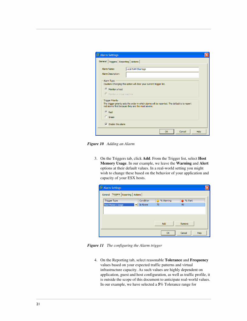
Figure 10 Adding an Alarm
3. On the Triggers tab, click Add. From the Trigger list, select Host Memory Usage. In our example, we leave the Warning and Alert options at their default values. In a real-world setting you might wish to change these based on the behavior of your application and capacity of your ESX hosts.
Figure 11 The configuring the Alarm trigger
4. On the Reporting tab, select reasonable Tolerance and Frequency values based on your expected traffic patterns and virtual infrastructure capacity. As such values are highly dependent on application, guest and host configuration, as well as traffic profile, it is outside the scope of this document to anticipate real-world values. In our example, we have selected a 5% Tolerance range for
21

Deploying F5 Automated Network Provisioning for VMware Infrastructure
repeating an alarm, and a 300 second (5 minute) Frequency value to allow our intended mitigation steps of bringing a new guest online time to alleviate the CPU resource starvation within the guest.
Figure 12 Configuring the reporting options
5. On the Actions tab, click Add. Place your mouse over the default action to open the drop-down list, and change the default value to Run a script. Click to deselect the default value of From Yellow to Red and click the From Green to Yellow box. In the Value section, click into the field to get a curser. In the box, type, as one line, the path to your script to bring a virtual machine guest out of suspended state that you created above, and the required arguments. In our example, we type:
powershell -noprofile -noexit -command "c:\Program Files\VMware\Infrastructure\VIToolkitForWindows\Scripts\EnableRemoteWeb.ps1"
Figure 13 Configuring the Alarm actions
F5® Deployment Guide 22

Note: Although our example in the Steps above and below are shown on more than one line because of space limitation, it should be entered as a single line within the Virtual Infrastructure Client GUI.
6. In the same Actions tab, select Add again. Change the new Action to Run a script. This time, leave the default threshold for the new value as From yellow to red. In the Value field, type the path and arguments to the F5 iControl PowerShell script you created above to add the new VM to the correct pool. In our example, we type:
powershell -noprofile -noexit -command "c:\Program Files\F5 Networks\iControlSnapIn\EnableRemoteDatacenter. ps1 <GTM FQDN or IP address> <GTM username> <GTM password> Remote"
Replace the values in brackets with values from your BIG-IP GTM system (do not include the brackets).
Figure 14 Configuring a second action
Note: Although our example in the Value section above is shown on more than one line because of space limitation, it should be entered as a single line within the Virtual Infrastructure Client GUI.
7. When completed with this step, click OK to complete the Alarm configuration.
The script in Appendix B: Script code for example 2, on page 25 is an adaptation of the examples presented at devcentral.f5.com/wiki/default.aspx/iControl/PsGtmDataCenter.html. The script for this guide has been modified with much of the debugging logic and output removed for readability, and because the script is intended to be run in non-interactive mode.
This completes the configuration.
23
Deploying F5 Automated Network Provisioning for VMware Infrastructure
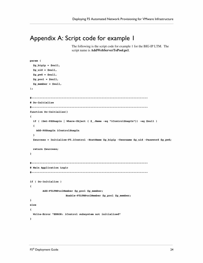
Appendix A: Script code for example 1The following is the script code for example 1 for the BIG-IP LTM. The script name is AddWebServerToPool.ps1.
param (
$g_bigip = $null,
$g_uid = $null,
$g_pwd = $null,
$g_pool = $null,
$g_member = $null,
);
#-------------------------------------------------------------------------
# Do-Initialize
#-------------------------------------------------------------------------
function Do-Initialize()
{
if ( (Get-PSSnapin | Where-Object { $_.Name -eq "iControlSnapIn"}) -eq $null )
{
Add-PSSnapIn iControlSnapIn
}
$success = Initialize-F5.iControl -HostName $g_bigip -Username $g_uid -Password $g_pwd;
return $success;
}
#-------------------------------------------------------------------------
# Main Application Logic
#-------------------------------------------------------------------------
if ( Do-Initialize )
{
Add-F5LTMPoolMember $g_pool $g_member;
Enable-F5LTMPoolMember $g_pool $g_member;
}
else
{
Write-Error "ERROR: iControl subsystem not initialized"
}
F5® Deployment Guide 24

Appendix B: Script code for example 2The following is the script code for example 2 for the BIG-IP GTM. The script name is EnableRemoteDatacenter.ps1.
param (
$g_bigip = $null,
$g_uid = $null,
$g_pwd = $null,
$g_name = $null,
);
#-------------------------------------------------------------------------
# Set-DataCenterEnabledState
#-------------------------------------------------------------------------
function Set-DataCenterEnabledState()
{
param([string]$name = $null, [string]$state = $null);
if ( $name -and $state )
{
$EnabledState = "STATE_DISABLED";
if ( $state -eq "enabled" ) { $EnabledState = "STATE_ENABLED"; }
(Get-F5.iControl).GlobalLBDataCenter.set_enabled_state(
(, $name),
(, $EnabledState)
);
Get-DataCenterList $name;
}
}
#-------------------------------------------------------------------------
# Do-Initialize
#-------------------------------------------------------------------------
function Do-Initialize()
{
if ( (Get-PSSnapin | Where-Object { $_.Name -eq "iControlSnapIn"}) -eq $null )
{
Add-PSSnapIn iControlSnapIn
}
$success = Initialize-F5.iControl -HostName $g_bigip -Username $g_uid -Password $g_pwd;
return $success;
}
#-------------------------------------------------------------------------
25

Deploying F5 Automated Network Provisioning for VMware Infrastructure
# Main Application Logic
#-------------------------------------------------------------------------
if ( ($g_bigip -eq $null) -or ($g_uid -eq $null) -or ($g_pwd -eq $null) )
{
Write-Usage;
}
if ( Do-Initialize )
{
Set-DataCenterEnabledState $g_name enabled;
}
else
{
Write-Error "ERROR: iControl subsystem not initialized"
}
F5® Deployment Guide 26


![PowerShell Basics - 1 PowerShell Basics - 2 VMware ...€¦ · Out-GridView [-InputObject ] # PowerShell 2 CTP3 & .net Framework 3.5 required Get-VM | Out-GridView](https://img.dokumen.tips/doc/110x75/5f8511013bb95c25160af588/powershell-basics-1-powershell-basics-2-vmware-out-gridview-inputobject.jpg)


![[Webinar] PowerShell series part 3 – PowerShell and WMI](https://img.dokumen.tips/doc/110x75/559b61c31a28ab125f8b47a2/webinar-powershell-series-part-3-powershell-and-wmi.jpg)