Embed Size (px)
Citation preview
August 2, 2013
By
Reference Architecture Guide
Deploy Hitachi Unified Compute Platform Select for VMware vSphere using Hitachi NAS Platform with Hitachi Unified Storage VM
Michael Nakamura
FeedbackHitachi Data Systems welcomes your feedback. Please share your thoughts by sending an email message to [email protected]. To assist the routing of this message, use the paper number in the subject and the title of this white paper in the text.
Table of ContentsSolution Overview.............. .................................................................................3
Key Solution Components..................................................................................5
Hardware Components.............................................................................5Software Components............... ...............................................................8
Solution Design.............. .....................................................................................9
Infrastructure Cell for Compute Resources............... .............................11Infrastructure Cell for Storage Resources............... ...............................17Infrastructure Cell for Hitachi NAS Platform Resources............... ..........19Application Cell for Hitachi Unified Compute Platform Select Management...........................................................................................23Application Cell for VMware vSphere............... ......................................26
Engineering Validation......................................................................................35
Test Methodology............... ....................................................................35Application Performance.........................................................................40Test Results............................................................................................40
Conclusion.............. ...........................................................................................52
1
1
Deploy Hitachi Unified Compute Platform Select for VMware vSphere using Hitachi NAS Platform with Hitachi Unified Storage VMReference Architecture Guide
Hitachi Unified Compute Platform Select with VMware vSphere using Hitachi NAS Platform with Hitachi Unified Storage VM is a Network File System (NFS)-based storage solution. You can integrate this environment with an existing SAN solution.
This reference architecture guide contains advice on how to build a virtual infrastructure that meets the unique requirements of your organization. It provides the flexibility to scale out the environment as organizational needs grow. The benefits of this solution include the following:
Faster deployment
Reduced risk
Predictability
Ability to scale out
Lower cost of ownership
Hitachi Unified Compute Platform Select is a family of completely integrated and flexible solutions. Each solution is configured for immediate deployment to run top-tier infrastructure applications without over-purchasing or provisioning unnecessary equipment. Each custom-built solution has its entire solution stack-certified. There are no compatibility issues.
This reference architecture guide focuses on designing a virtual infrastructure capable of hosting virtual machines running general server application workloads.
Hitachi Data Systems strongly recommends that you run a server capacity-planning pilot to gather sizing and IOPS information before designing your environment.
2
2
You need familiarity with the use and configuration of the following to use this reference architecture guide:
Hitachi NAS Platform
Hitachi Unified Storage VM
Hitachi Compute Blade 500
VMware vSphere 5
Note — Testing of this configuration was in a lab environment. Many things affect production environments beyond prediction or duplication in a lab environment. Follow the recommended practice of conducting proof-of-concept testing for acceptable results in a non-production, isolated test environment that otherwise matches your production environment before your production implementation of this solution.
3
3
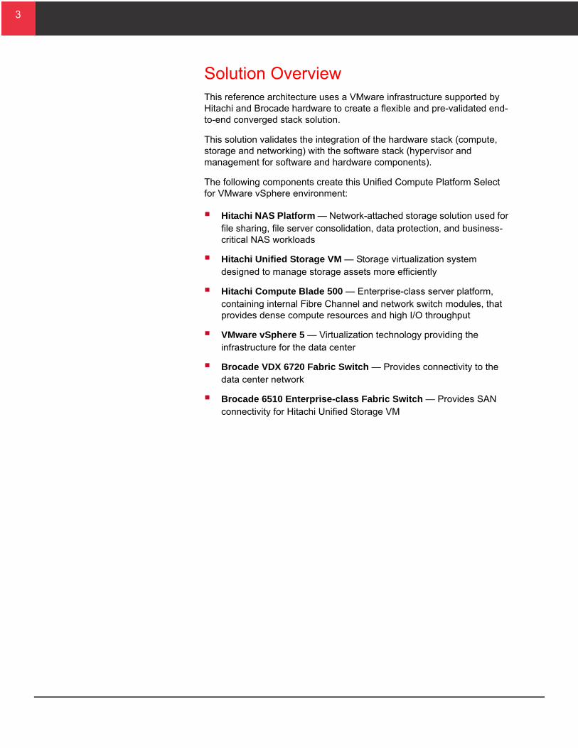
Solution OverviewThis reference architecture uses a VMware infrastructure supported by Hitachi and Brocade hardware to create a flexible and pre-validated end-to-end converged stack solution.
This solution validates the integration of the hardware stack (compute, storage and networking) with the software stack (hypervisor and management for software and hardware components).
The following components create this Unified Compute Platform Select for VMware vSphere environment:
Hitachi NAS Platform — Network-attached storage solution used for file sharing, file server consolidation, data protection, and business-critical NAS workloads
Hitachi Unified Storage VM — Storage virtualization system designed to manage storage assets more efficiently
Hitachi Compute Blade 500 — Enterprise-class server platform, containing internal Fibre Channel and network switch modules, that provides dense compute resources and high I/O throughput
VMware vSphere 5 — Virtualization technology providing the infrastructure for the data center
Brocade VDX 6720 Fabric Switch — Provides connectivity to the data center network
Brocade 6510 Enterprise-class Fabric Switch — Provides SAN connectivity for Hitachi Unified Storage VM
4
4
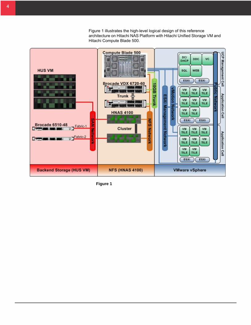
Figure 1 illustrates the high-level logical design of this reference architecture on Hitachi NAS Platform with Hitachi Unified Storage VM and Hitachi Compute Blade 500.
Figure 1
5
5
T
Key Solution ComponentsThese are descriptions of the key hardware and software components used to deploy this Hitachi Unified Compute Platform Select for VMware vSphere reference solution with Hitachi NAS Platform.
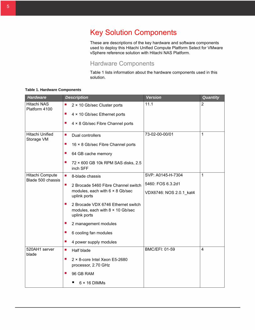
Hardware ComponentsTable 1 lists information about the hardware components used in this solution.
able 1. Hardware Components
Hardware Description Version Quantity
Hitachi NAS Platform 4100
2 × 10 Gb/sec Cluster ports
4 × 10 Gb/sec Ethernet ports
4 × 8 Gb/sec Fibre Channel ports
11.1 2
Hitachi Unified Storage VM
Dual controllers
16 × 8 Gb/sec Fibre Channel ports
64 GB cache memory
72 × 600 GB 10k RPM SAS disks, 2.5 inch SFF
73-02-00-00/01 1
Hitachi Compute Blade 500 chassis
8-blade chassis
2 Brocade 5460 Fibre Channel switch modules, each with 6 × 8 Gb/sec uplink ports
2 Brocade VDX 6746 Ethernet switch modules, each with 8 × 10 Gb/sec uplink ports
2 management modules
6 cooling fan modules
4 power supply modules
SVP: A0145-H-7304
5460: FOS 6.3.2d1
VDX6746: NOS 2.0.1_kat4
1
520AH1 server blade
Half blade
2 × 8-core Intel Xeon E5-2680 processor, 2.70 GHz
96 GB RAM
6 × 16 DIMMs
BMC/EFI: 01-59 4
6
6
T
Hitachi NAS PlatformHitachi NAS Platform is an advanced and integrated network attached storage (NAS) solution. It provides a powerful tool for file sharing, file server consolidation, data protection, and business-critical NAS workloads.
Powerful hardware-accelerated file system with multi-protocol file services, dynamic provisioning, intelligent tiering, virtualization, and cloud infrastructure
Seamless integration with Hitachi SAN storage, Hitachi Command Suite, and Hitachi Data Discovery Suite for advanced search and index
Integration with Hitachi Content Platform for active archiving, regulatory compliance, and large object storage for cloud infrastructure
Take advantage of the following features for better management and tighter integration of your Hitachi NAS environment with your VMware infrastructure.
Hitachi NAS Virtual Infrastructure Integrator — Simplify virtual machine backup, restoration, cloning, and NFS datastore management
VMware vSphere API for Array Integration — Enables the ESXi host to offload certain storage operations to the storage array
VMware vSphere API for Storage Awareness — Shows storage capabilities
Hitachi NAS Deduplication — Reclaim up to 90% of unstructured data storage capacity, to extend the life of existing storage assets
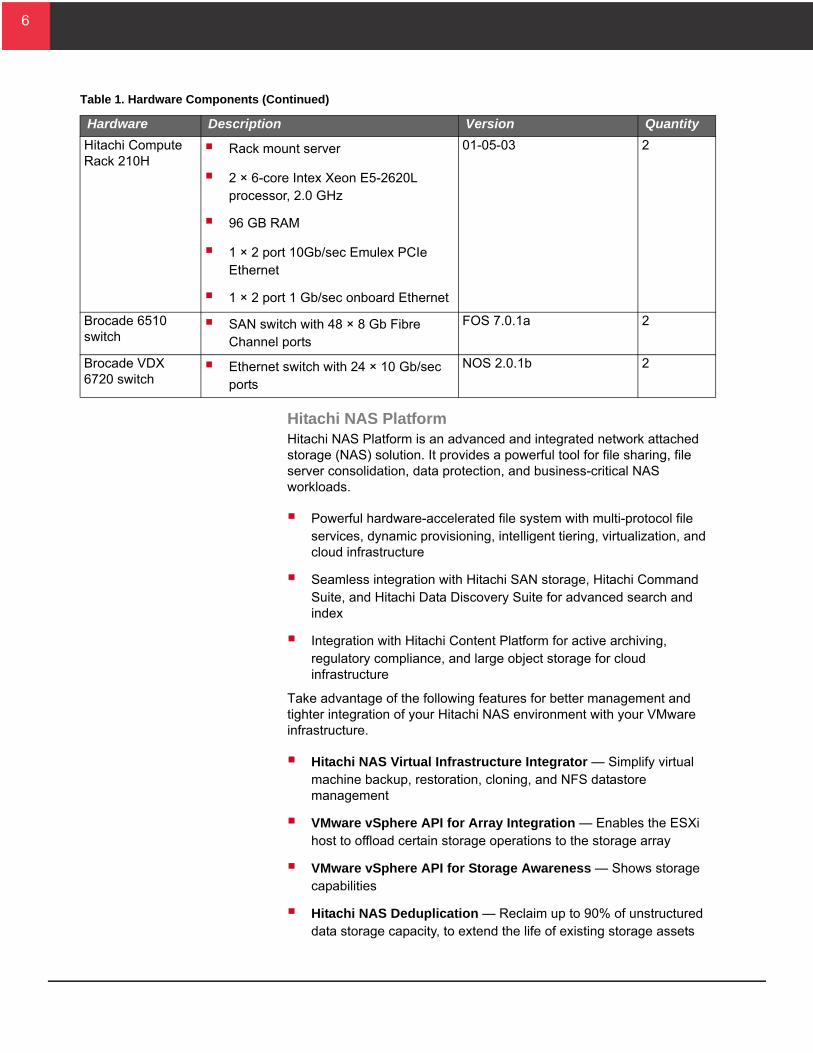
Hitachi Compute Rack 210H
Rack mount server
2 × 6-core Intex Xeon E5-2620L processor, 2.0 GHz
96 GB RAM
1 × 2 port 10Gb/sec Emulex PCIe Ethernet
1 × 2 port 1 Gb/sec onboard Ethernet
01-05-03 2
Brocade 6510 switch
SAN switch with 48 × 8 Gb Fibre Channel ports
FOS 7.0.1a 2
Brocade VDX 6720 switch
Ethernet switch with 24 × 10 Gb/sec ports
NOS 2.0.1b 2
able 1. Hardware Components (Continued)
Hardware Description Version Quantity
7
7
Hitachi Unified Storage VMHitachi Unified Storage VM is an entry-level enterprise storage platform. It combines storage virtualization services with unified block, file, and object data management. This versatile, scalable platform offers a storage virtualization system to provide central storage services to existing storage assets.
Unified management delivers end-to-end central storage management of all virtualized internal and external storage on Unified Storage VM. A unique, hardware-accelerated, object-based file system supports intelligent file tiering and migration, as well as virtual NAS functionality, without compromising performance or scalability.
The benefits of Unified Storage VM are the following:
Enables the move to a new storage platform with less effort and cost when compared to the industry average
Increases performance and lowers operating cost with automated data placement
Supports scalable management for growing and complex storage environment while using fewer resources
Achieves better power efficiency and with more storage capacity for more sustainable data centers
Lowers operational risk and data loss exposure with data resilience solutions
Consolidates management with end-to-end virtualization to prevent virtual server sprawl
Hitachi Compute Blade 500Hitachi Compute Blade 500 combines the high-end features with the high compute density and adaptable architecture you need to lower costs and protect investment. Safely mix a wide variety of application workloads on a highly reliable, scalable, and flexible platform. Add server management and system monitoring at no cost with Hitachi Compute Systems Manager, which can seamlessly integrate with Hitachi Command Suite in IT environments using Hitachi storage.
The Hitachi Compute Blade 500 chassis contains internal Fibre Channel and network switches for the high availability requirements of Hitachi Unified Compute Platform Select for VMware vSphere.
8
8
T
Brocade Storage Area Network SwitchesBrocade and Hitachi Data Systems have collaborated to deliver storage networking and data center solutions. These solutions reduce complexity and cost, as well as enable virtualization and cloud computing to increase business agility.
This reference architecture uses the following Brocade products:
Brocade 6510 Switch
Brocade VDX 6720 Data Center Switch
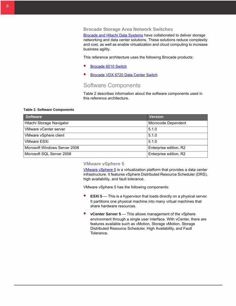
Software ComponentsTable 2 describes information about the software components used in this reference architecture.
VMware vSphere 5VMware vSphere 5 is a virtualization platform that provides a data center infrastructure. It features vSphere Distributed Resource Scheduler (DRS), high availability, and fault tolerance.
VMware vSphere 5 has the following components:
ESXi 5 — This is a hypervisor that loads directly on a physical server. It partitions one physical machine into many virtual machines that share hardware resources.
vCenter Server 5 — This allows management of the vSphere environment through a single user interface. With vCenter, there are features available such as vMotion, Storage vMotion, Storage Distributed Resource Scheduler, High Availability, and Fault Tolerance.
able 2. Software Components
Software Version
Hitachi Storage Navigator Microcode Dependent
VMware vCenter server 5.1.0
VMware vSphere client 5.1.0
VMware ESXi 5.1.0
Microsoft Windows Server 2008 Enterprise edition, R2
Microsoft SQL Server 2008 Enterprise edition, R2
9
9
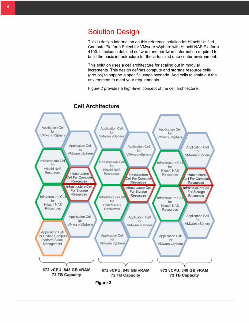
Solution DesignThis is design information on this reference solution for Hitachi Unified Compute Platform Select for VMware vSphere with Hitachi NAS Platform 4100. It includes detailed software and hardware information required to build the basic infrastructure for the virtualized data center environment.
This solution uses a cell architecture for scaling out in modular increments. This design defines compute and storage resource cells (groups) to support a specific usage scenario. Add cells to scale out the environment to meet your requirements.
Figure 2 provides a high-level concept of the cell architecture.
Figure 2
10
10
The architecture consists of preconfigured cells designed to support general server workload. These cells provide the following:
Infrastructure cell for compute resources — Foundation for compute components
Infrastructure cell for storage resources — Foundation for storage components
Infrastructure cell for Hitachi NAS Platform resources — Foundation for NAS Platform components
Application cell for Unified Compute Platform Select management — Resource to manage this environment
This cell is required only if an existing configuration for managing a VMware vSphere environment does not exist.
Application cell for VMware vSphere — Provides the resource for hosting virtual machines running general server application workloads.
Expansion cell for compute resources — Provides the compute resources for scaling out the Unified Compute Platform Select for VMware vSphere environment.
Expansion cell for storage resources — Provides the storage resources for scaling out the Unified Compute Platform Select for VMware vSphere environment.
These cells provide the compute and storage hardware needed to build this scalable Hitachi Unified Compute Platform Select for VMware vSphere solution.
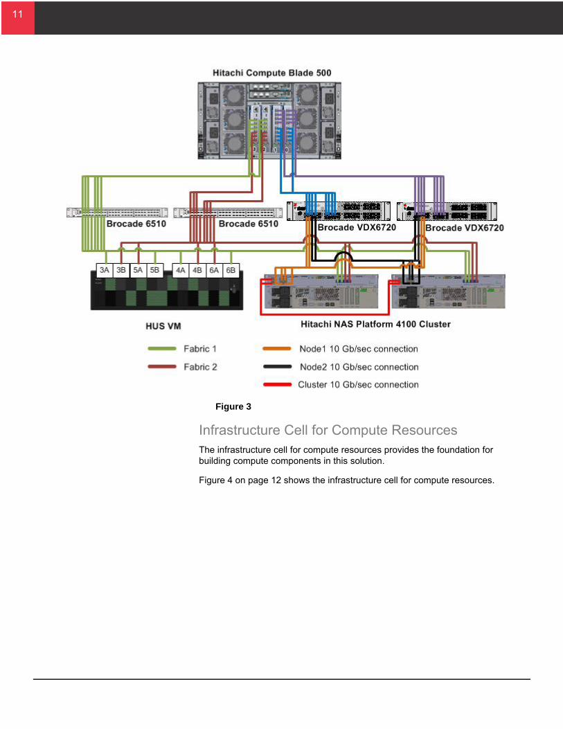
Figure 3 on page 11 provides an overview of the infrastructure connectivity.
11
11
Figure 3
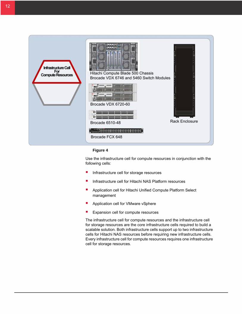
Infrastructure Cell for Compute ResourcesThe infrastructure cell for compute resources provides the foundation for building compute components in this solution.
Figure 4 on page 12 shows the infrastructure cell for compute resources.
12
12
Figure 4
Use the infrastructure cell for compute resources in conjunction with the following cells:
Infrastructure cell for storage resources
Infrastructure cell for Hitachi NAS Platform resources
Application cell for Hitachi Unified Compute Platform Select management
Application cell for VMware vSphere
Expansion cell for compute resources
The infrastructure cell for compute resources and the infrastructure cell for storage resources are the core infrastructure cells required to build a scalable solution. Both infrastructure cells support up to two infrastructure cells for Hitachi NAS resources before requiring new infrastructure cells. Every infrastructure cell for compute resources requires one infrastructure cell for storage resources.
13
13
T
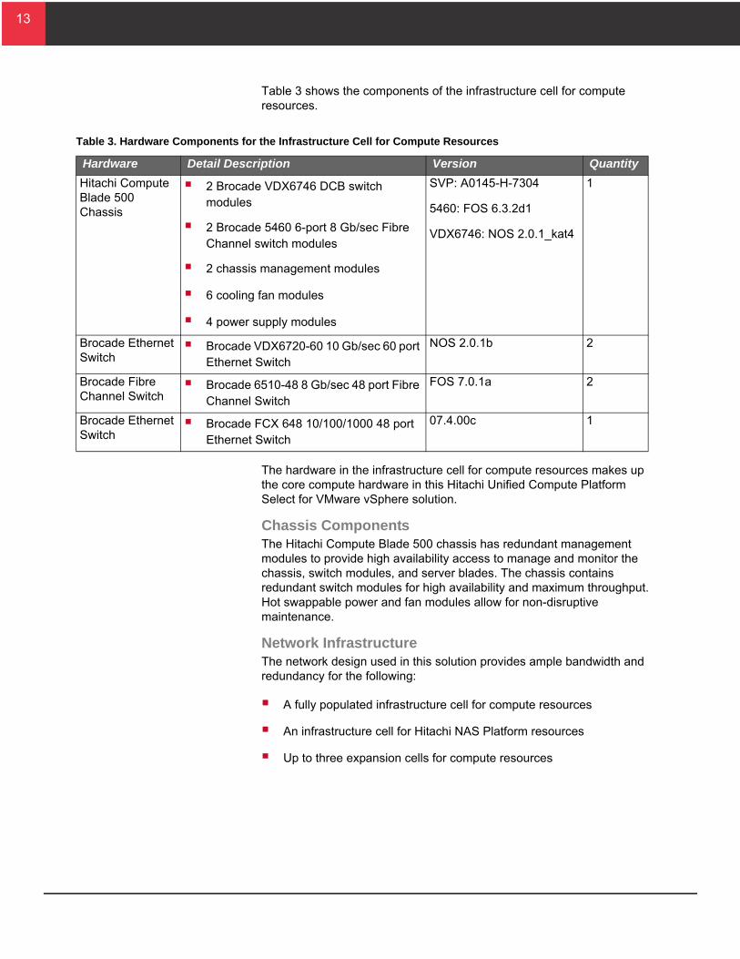
Table 3 shows the components of the infrastructure cell for compute resources.
The hardware in the infrastructure cell for compute resources makes up the core compute hardware in this Hitachi Unified Compute Platform Select for VMware vSphere solution.
Chassis ComponentsThe Hitachi Compute Blade 500 chassis has redundant management modules to provide high availability access to manage and monitor the chassis, switch modules, and server blades. The chassis contains redundant switch modules for high availability and maximum throughput. Hot swappable power and fan modules allow for non-disruptive maintenance.
Network InfrastructureThe network design used in this solution provides ample bandwidth and redundancy for the following:
A fully populated infrastructure cell for compute resources
An infrastructure cell for Hitachi NAS Platform resources
Up to three expansion cells for compute resources
able 3. Hardware Components for the Infrastructure Cell for Compute Resources
Hardware Detail Description Version Quantity
Hitachi Compute Blade 500 Chassis
2 Brocade VDX6746 DCB switch modules
2 Brocade 5460 6-port 8 Gb/sec Fibre Channel switch modules
2 chassis management modules
6 cooling fan modules
4 power supply modules
SVP: A0145-H-7304
5460: FOS 6.3.2d1
VDX6746: NOS 2.0.1_kat4
1
Brocade Ethernet Switch
Brocade VDX6720-60 10 Gb/sec 60 port Ethernet Switch
NOS 2.0.1b 2
Brocade Fibre Channel Switch
Brocade 6510-48 8 Gb/sec 48 port Fibre Channel Switch
FOS 7.0.1a 2
Brocade Ethernet Switch
Brocade FCX 648 10/100/1000 48 port Ethernet Switch
07.4.00c 1
14
14
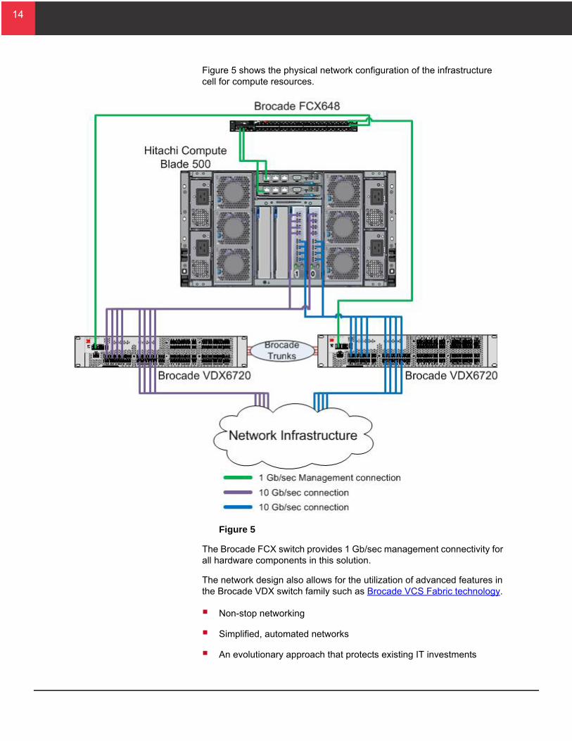
Figure 5 shows the physical network configuration of the infrastructure cell for compute resources.
Figure 5
The Brocade FCX switch provides 1 Gb/sec management connectivity for all hardware components in this solution.
The network design also allows for the utilization of advanced features in the Brocade VDX switch family such as Brocade VCS Fabric technology.
Non-stop networking
Simplified, automated networks
An evolutionary approach that protects existing IT investments
15
15
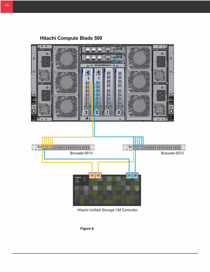
SAN Infrastructure (Optional)For this file services-based reference architecture, direct access from the Hitachi Compute Blade 500 chassis to the SAN infrastructure is not a requirement because the environment presents storage resources through the network. Consider this option when designing a hybrid architecture, when you need access to file storage resources and block storage resources.
The Hitachi Unified Storage VM controller used for this solution has 16 ports for connections to the Brocade 6510 enterprise Fabric switches. Zone the infrastructure cell for compute resources to four ports on the Hitachi Unified Storage VM controller, two ports per cluster. When adding an expansion cell for compute resources to the solution, zone four new open storage ports on the cluster.
Dedicating four ports to each Hitachi Compute Blade 500 chassis ensures sufficient bandwidth between the chassis and Hitachi Unified Storage VM.
Figure 6 on page 16 illustrates the physical SAN architecture of the infrastructure cell for compute.
16
16
Figure 6
17
17
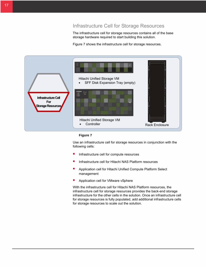
Infrastructure Cell for Storage ResourcesThe infrastructure cell for storage resources contains all of the base storage hardware required to start building this solution.
Figure 7 shows the infrastructure cell for storage resources.
Figure 7
Use an infrastructure cell for storage resources in conjunction with the following cells:
Infrastructure cell for compute resources
Infrastructure cell for Hitachi NAS Platform resources
Application cell for Hitachi Unified Compute Platform Select management
Application cell for VMware vSphere
With the infrastructure cell for Hitachi NAS Platform resources, the infrastructure cell for storage resources provides the back-end storage infrastructure for the other cells in the solution. Once an infrastructure cell for storage resources is fully populated, add additional infrastructure cells for storage resources to scale out the solution.
18
18
T
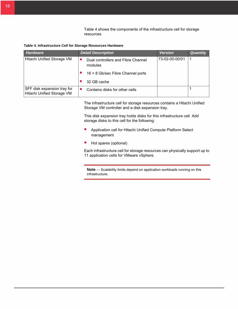
Table 4 shows the components of the infrastructure cell for storage resources.
The infrastructure cell for storage resources contains a Hitachi Unified Storage VM controller and a disk expansion tray.
This disk expansion tray holds disks for this infrastructure cell. Add storage disks to this cell for the following:
Application cell for Hitachi Unified Compute Platform Select management
Hot spares (optional)
Each infrastructure cell for storage resources can physically support up to 11 application cells for VMware vSphere.
Note — Scalability limits depend on application workloads running on this infrastructure.
able 4. Infrastructure Cell for Storage Resources Hardware
Hardware Detail Description Version Quantity
Hitachi Unified Storage VM Dual controllers and Fibre Channel modules
16 × 8 Gb/sec Fibre Channel ports
32 GB cache
73-02-00-00/01 1
SFF disk expansion tray for Hitachi Unified Storage VM
Contains disks for other cells 1
19
19
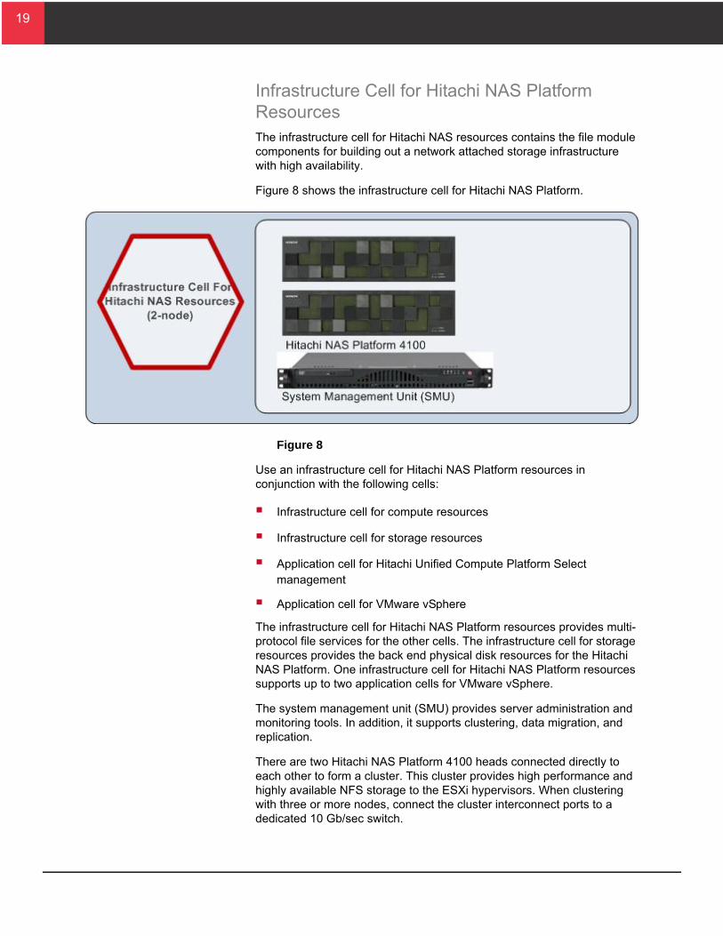
Infrastructure Cell for Hitachi NAS Platform ResourcesThe infrastructure cell for Hitachi NAS resources contains the file module components for building out a network attached storage infrastructure with high availability.
Figure 8 shows the infrastructure cell for Hitachi NAS Platform.
Figure 8
Use an infrastructure cell for Hitachi NAS Platform resources in conjunction with the following cells:
Infrastructure cell for compute resources
Infrastructure cell for storage resources
Application cell for Hitachi Unified Compute Platform Select management
Application cell for VMware vSphere
The infrastructure cell for Hitachi NAS Platform resources provides multi-protocol file services for the other cells. The infrastructure cell for storage resources provides the back end physical disk resources for the Hitachi NAS Platform. One infrastructure cell for Hitachi NAS Platform resources supports up to two application cells for VMware vSphere.
The system management unit (SMU) provides server administration and monitoring tools. In addition, it supports clustering, data migration, and replication.
There are two Hitachi NAS Platform 4100 heads connected directly to each other to form a cluster. This cluster provides high performance and highly available NFS storage to the ESXi hypervisors. When clustering with three or more nodes, connect the cluster interconnect ports to a dedicated 10 Gb/sec switch.
20
20
T
A LUN presented from Hitachi Unified Storage VM to Hitachi NAS Platform 4100 is called a system drive. A storage pool is the logical container for one or more system drives. The storage pool can be expanded by adding storage drives to the pool.
Create one or more file systems from a storage pool. The file system is the primary storage component in Hitachi NAS Platform. All other features directly or indirectly support file systems.
For this solution, the VMware vSphere infrastructure uses NFS exports from a file system to connect to the storage resources provided by Hitachi NAS Platform 4100.
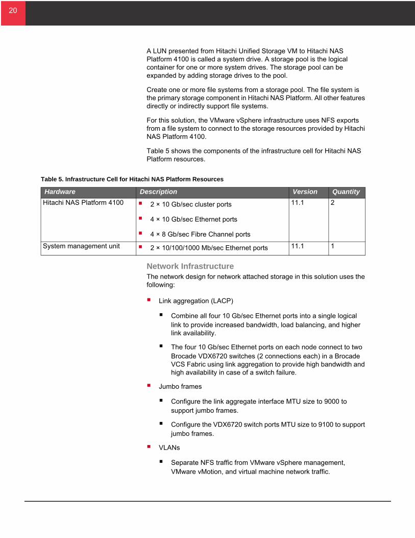
Table 5 shows the components of the infrastructure cell for Hitachi NAS Platform resources.
Network InfrastructureThe network design for network attached storage in this solution uses the following:
Link aggregation (LACP)
Combine all four 10 Gb/sec Ethernet ports into a single logical link to provide increased bandwidth, load balancing, and higher link availability.
The four 10 Gb/sec Ethernet ports on each node connect to two Brocade VDX6720 switches (2 connections each) in a Brocade VCS Fabric using link aggregation to provide high bandwidth and high availability in case of a switch failure.
Jumbo frames
Configure the link aggregate interface MTU size to 9000 to support jumbo frames.
Configure the VDX6720 switch ports MTU size to 9100 to support jumbo frames.
VLANs
Separate NFS traffic from VMware vSphere management, VMware vMotion, and virtual machine network traffic.
able 5. Infrastructure Cell for Hitachi NAS Platform Resources
Hardware Description Version Quantity
Hitachi NAS Platform 4100 2 × 10 Gb/sec cluster ports
4 × 10 Gb/sec Ethernet ports
4 × 8 Gb/sec Fibre Channel ports
11.1 2
System management unit 2 × 10/100/1000 Mb/sec Ethernet ports 11.1 1
21
21
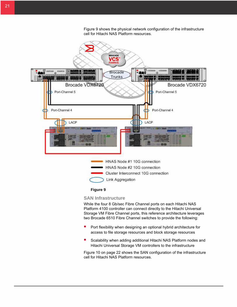
Figure 9 shows the physical network configuration of the infrastructure cell for Hitachi NAS Platform resources.
Figure 9
SAN InfrastructureWhile the four 8 Gb/sec Fibre Channel ports on each Hitachi NAS Platform 4100 controller can connect directly to the Hitachi Universal Storage VM Fibre Channel ports, this reference architecture leverages two Brocade 6510 Fibre Channel switches to provide the following:
Port flexibility when designing an optional hybrid architecture for access to file storage resources and block storage resources
Scalability when adding additional Hitachi NAS Platform nodes and Hitachi Universal Storage VM controllers to the infrastructure
Figure 10 on page 22 shows the SAN configuration of the infrastructure cell for Hitachi NAS Platform resources.
22
22
T
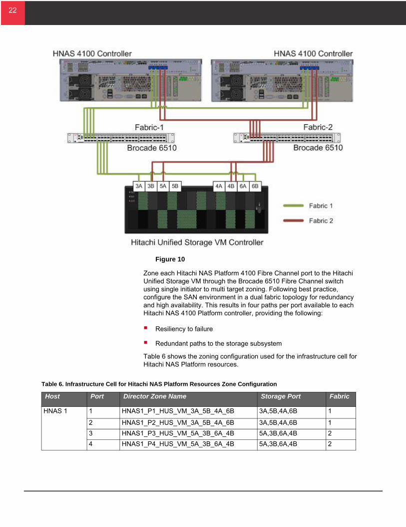
Figure 10
Zone each Hitachi NAS Platform 4100 Fibre Channel port to the Hitachi Unified Storage VM through the Brocade 6510 Fibre Channel switch using single initiator to multi target zoning. Following best practice, configure the SAN environment in a dual fabric topology for redundancy and high availability. This results in four paths per port available to each Hitachi NAS 4100 Platform controller, providing the following:
Resiliency to failure
Redundant paths to the storage subsystem
Table 6 shows the zoning configuration used for the infrastructure cell for Hitachi NAS Platform resources.
able 6. Infrastructure Cell for Hitachi NAS Platform Resources Zone Configuration
Host Port Director Zone Name Storage Port Fabric
HNAS 1 1 HNAS1_P1_HUS_VM_3A_5B_4A_6B 3A,5B,4A,6B 1
2 HNAS1_P2_HUS_VM_3A_5B_4A_6B 3A,5B,4A,6B 1
3 HNAS1_P3_HUS_VM_5A_3B_6A_4B 5A,3B,6A,4B 2
4 HNAS1_P4_HUS_VM_5A_3B_6A_4B 5A,3B,6A,4B 2
23
23
T
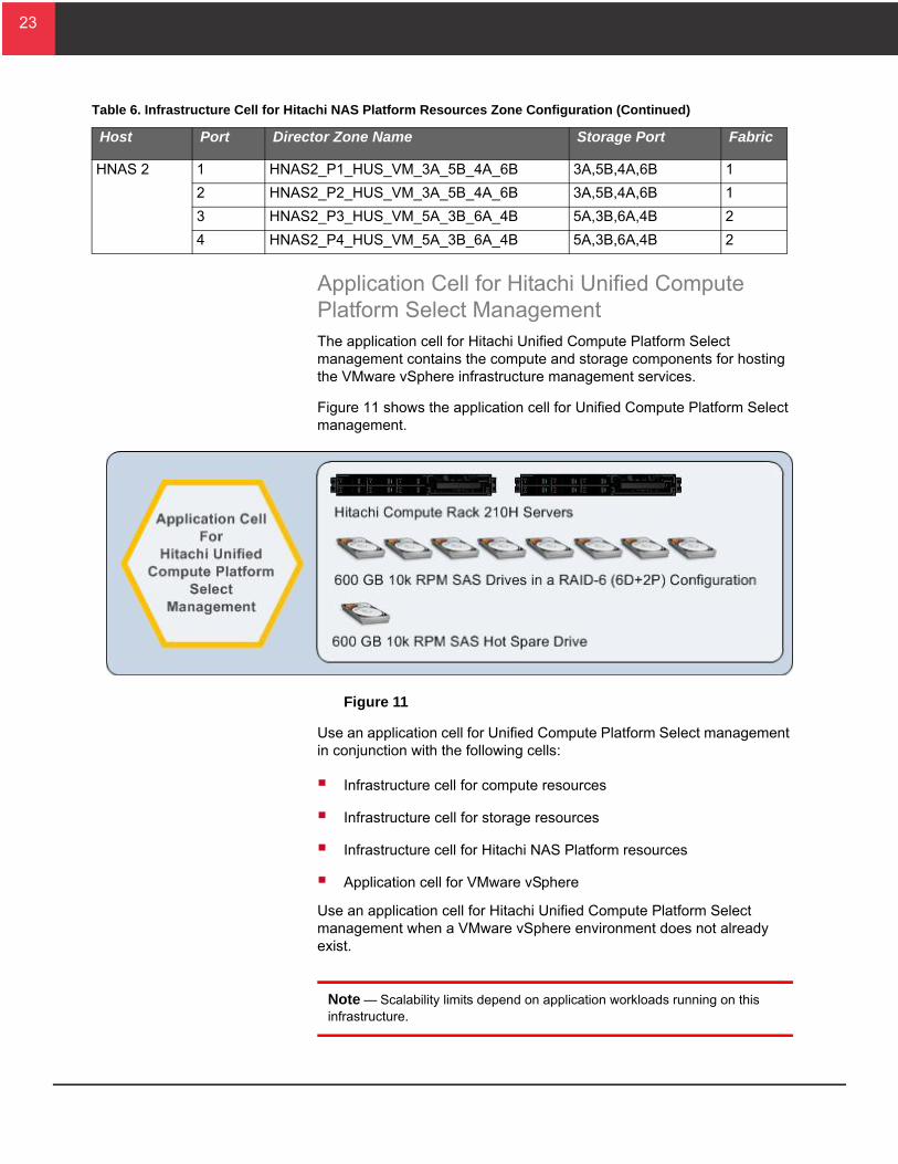
Application Cell for Hitachi Unified Compute Platform Select ManagementThe application cell for Hitachi Unified Compute Platform Select management contains the compute and storage components for hosting the VMware vSphere infrastructure management services.
Figure 11 shows the application cell for Unified Compute Platform Select management.
Figure 11
Use an application cell for Unified Compute Platform Select management in conjunction with the following cells:
Infrastructure cell for compute resources
Infrastructure cell for storage resources
Infrastructure cell for Hitachi NAS Platform resources
Application cell for VMware vSphere
Use an application cell for Hitachi Unified Compute Platform Select management when a VMware vSphere environment does not already exist.
Note — Scalability limits depend on application workloads running on this infrastructure.
HNAS 2 1 HNAS2_P1_HUS_VM_3A_5B_4A_6B 3A,5B,4A,6B 1
2 HNAS2_P2_HUS_VM_3A_5B_4A_6B 3A,5B,4A,6B 1
3 HNAS2_P3_HUS_VM_5A_3B_6A_4B 5A,3B,6A,4B 2
4 HNAS2_P4_HUS_VM_5A_3B_6A_4B 5A,3B,6A,4B 2
able 6. Infrastructure Cell for Hitachi NAS Platform Resources Zone Configuration (Continued)
Host Port Director Zone Name Storage Port Fabric
24
24
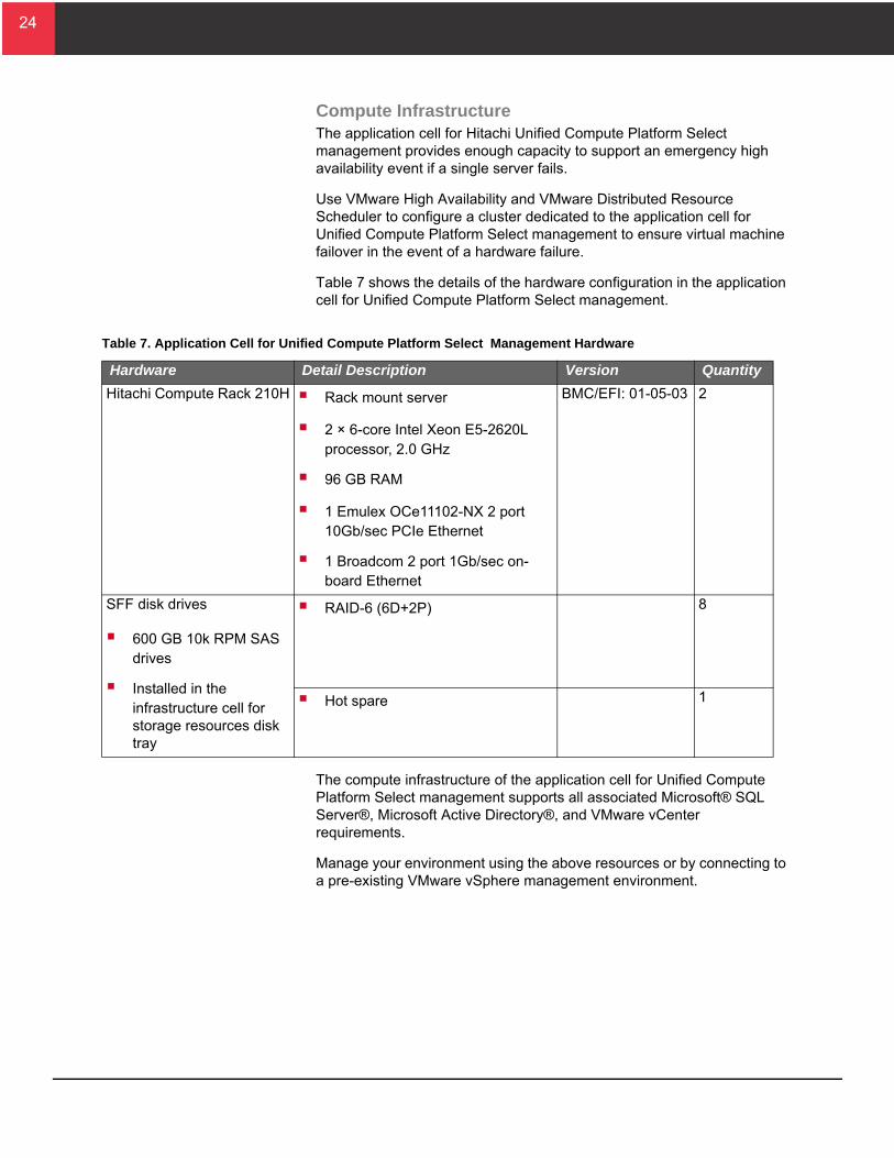
Compute InfrastructureThe application cell for Hitachi Unified Compute Platform Select management provides enough capacity to support an emergency high availability event if a single server fails.
Use VMware High Availability and VMware Distributed Resource Scheduler to configure a cluster dedicated to the application cell for Unified Compute Platform Select management to ensure virtual machine failover in the event of a hardware failure.
Table 7 shows the details of the hardware configuration in the application cell for Unified Compute Platform Select management.
The compute infrastructure of the application cell for Unified Compute Platform Select management supports all associated Microsoft® SQL Server®, Microsoft Active Directory®, and VMware vCenter requirements.
Manage your environment using the above resources or by connecting to a pre-existing VMware vSphere management environment.
Table 7. Application Cell for Unified Compute Platform Select Management Hardware
Hardware Detail Description Version Quantity
Hitachi Compute Rack 210H Rack mount server
2 × 6-core Intel Xeon E5-2620L processor, 2.0 GHz
96 GB RAM
1 Emulex OCe11102-NX 2 port 10Gb/sec PCIe Ethernet
1 Broadcom 2 port 1Gb/sec on-board Ethernet
BMC/EFI: 01-05-03 2
SFF disk drives
600 GB 10k RPM SAS drives
Installed in the infrastructure cell for storage resources disk tray
RAID-6 (6D+2P) 8
Hot spare 1
25
25
Network InfrastructureConfigure each Hitachi Compute Rack 210H server with a single Emulex OCe11102-NX 2 port 10 Gb/sec PCIe Ethernet card for network traffic.
This solution uses the following VLANs to separate network traffic in the application cell for VMware vSphere:
Management-VLAN — Chassis management connections and primary management of the ESXi hypervisors
vMotion-VLAN — Configured for VMware vMotion
VM-VLAN — Configured for the virtual machine network
NFS-VLAN — Configured for management applications that access infrastructure on the NFS VLAN
Following best practice, separate the management, vMotion, virtual machine, and NFS traffic to achieve greater security or better performance.
Team the two physical NICs to allow network path redundancy
Set the load balancing policy to “route based on IP hash”
With enhancements to VMware vSphere 5, the VMkernel load balances vMotion traffic over all vmkernel ports configured for vMotion. This improves performance and reduces migration times.
Storage InfrastructureThe storage infrastructure of the application cell for Hitachi Unified Compute Platform Select management consists of eight 600 GB 10k RPM SAS drives housed in the disk expansion tray contained in the infrastructure cell for storage resources.
Configure the storage into a single RAID-6 (6D+2P) LDEV. Present the storage as a system drive to the Hitachi NAS Platform 4100 node. Create a storage pool and file system dedicated to management servers. The pool provides an overall capacity of 3 TB.
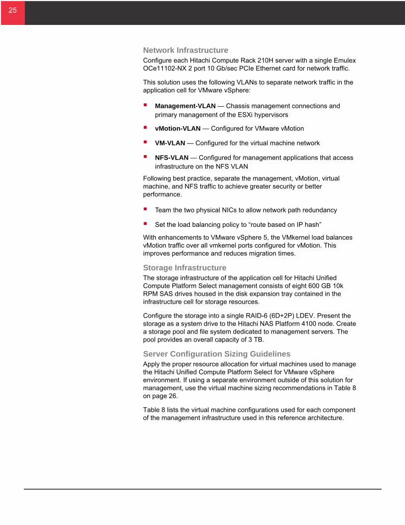
Server Configuration Sizing GuidelinesApply the proper resource allocation for virtual machines used to manage the Hitachi Unified Compute Platform Select for VMware vSphere environment. If using a separate environment outside of this solution for management, use the virtual machine sizing recommendations in Table 8 on page 26.
Table 8 lists the virtual machine configurations used for each component of the management infrastructure used in this reference architecture.
26
26
T
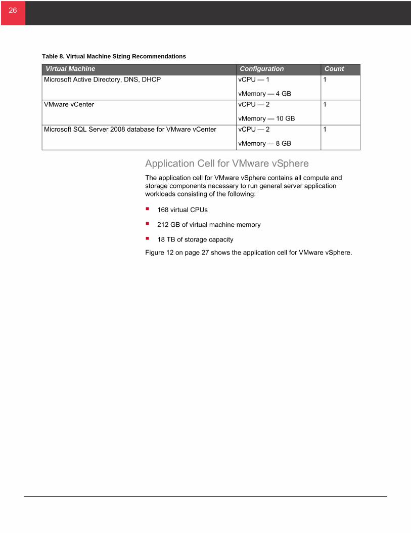
Application Cell for VMware vSphereThe application cell for VMware vSphere contains all compute and storage components necessary to run general server application workloads consisting of the following:
168 virtual CPUs
212 GB of virtual machine memory
18 TB of storage capacity
Figure 12 on page 27 shows the application cell for VMware vSphere.
able 8. Virtual Machine Sizing Recommendations
Virtual Machine Configuration Count
Microsoft Active Directory, DNS, DHCP vCPU — 1
vMemory — 4 GB
1
VMware vCenter vCPU — 2
vMemory — 10 GB
1
Microsoft SQL Server 2008 database for VMware vCenter vCPU — 2
vMemory — 8 GB
1
27
27
Figure 12
Use the application cell for VMware vSphere in conjunction with the following cells:
Infrastructure cell for compute resources
Infrastructure cell for storage resources
Infrastructure cell for Hitachi NAS Platform resources
Expansion cell for compute resources (used for scale-out)
Add the compute components of the application cell for VMware vSphere to the infrastructure cell for compute and the storage components to the infrastructure cell for storage to start building a scalable Hitachi Unified Compute Platform Select for VMware vSphere environment.
To scale out the solution and increase capacity, add additional application cells for VMware vSphere to the following:
Infrastructure cells for compute resources
Expansion cells for compute resources
28
28
This physically supports up to four application cells for VMware vSphere before there is need to add new infrastructure cells with the following:
1 infrastructure cell for compute resources
1 infrastructure cell for storage resources
2 infrastructure cells for Hitachi NAS Platform resources
Note — Scalability limits depend on application workloads running on this infrastructure.
Compute InfrastructureThe application cell for VMware vSphere supports a maximum density of the following:
168 virtual CPUs
212 GB of virtual machine memory
In a maximum density configuration, a cell cannot support the failover of virtual machines in case of a server blade failure. To provide high availability, do the following:
Reduce the number of virtual CPUs and virtual machine memory per host up to 50%.
Configure a VMware High Availability and VMware Distributed Resource Scheduler cluster dedicated to application cells for VMware vSphere.
Place additional hosts from each application cell for VMware vSphere into the cluster. When scaling the solution, increase the number of virtual machines per host as you add more resources to the cluster.
Based on VMware maximums, each High Availability and Distributed Resource Scheduler cluster can support up to 16 application cells for VMware vSphere (32 hosts).
29
29
T
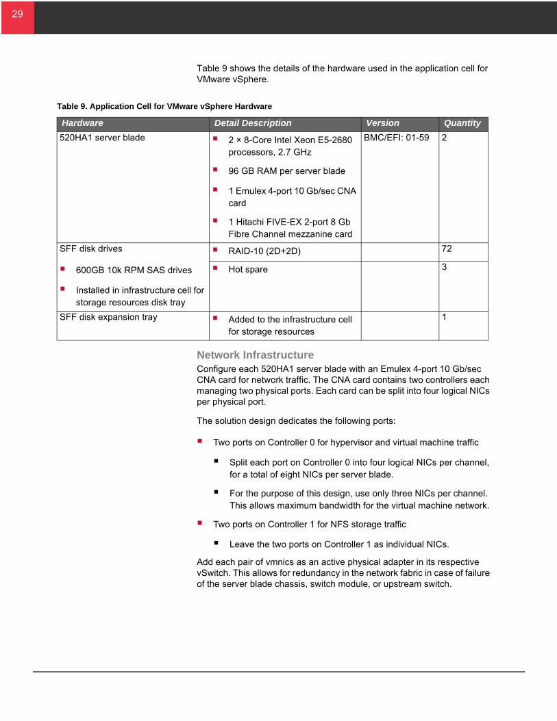
Table 9 shows the details of the hardware used in the application cell for VMware vSphere.
Network InfrastructureConfigure each 520HA1 server blade with an Emulex 4-port 10 Gb/sec CNA card for network traffic. The CNA card contains two controllers each managing two physical ports. Each card can be split into four logical NICs per physical port.
The solution design dedicates the following ports:
Two ports on Controller 0 for hypervisor and virtual machine traffic
Split each port on Controller 0 into four logical NICs per channel, for a total of eight NICs per server blade.
For the purpose of this design, use only three NICs per channel. This allows maximum bandwidth for the virtual machine network.
Two ports on Controller 1 for NFS storage traffic
Leave the two ports on Controller 1 as individual NICs.
Add each pair of vmnics as an active physical adapter in its respective vSwitch. This allows for redundancy in the network fabric in case of failure of the server blade chassis, switch module, or upstream switch.
able 9. Application Cell for VMware vSphere Hardware
Hardware Detail Description Version Quantity
520HA1 server blade 2 × 8-Core Intel Xeon E5-2680 processors, 2.7 GHz
96 GB RAM per server blade
1 Emulex 4-port 10 Gb/sec CNA card
1 Hitachi FIVE-EX 2-port 8 Gb Fibre Channel mezzanine card
BMC/EFI: 01-59 2
SFF disk drives
600GB 10k RPM SAS drives
Installed in infrastructure cell for storage resources disk tray
RAID-10 (2D+2D) 72
Hot spare 3
SFF disk expansion tray Added to the infrastructure cell for storage resources
1
30
30
Set bandwidth allocation for each NIC as follows:
Controller 0 — Channel 0 and 1 NIC 0 (vmnic0 and vmnic1)
Virtual machine management network
VMkernel management network vSwitch
1 Gb/sec per NIC, for a total of 2 Gb/sec
Controller 0 — Channel 0 and 1 NIC 1 (vmnic2 and vmnic3)
vMotion network
VMkernel vMotion network vSwitch
2 Gb/sec per NIC, for a total of 4 Gb/sec
Controller 0 — Channel 0 and 1 NIC 2 (vmnic4 and vmnic5)
Virtual machine network
Virtual machine network vSwitch
7 Gb/sec per NIC, for a total of 14 Gb/sec
Controller 1 — Channel 0 and 1 NIC 3 (vmnic8 and vmnic9)
NFS storage network
VMkernel NFS network vSwitch
10 Gb/sec per NIC, for a total of 20 Gb/sec
This solution uses the following VLANs to separate network traffic in the application cell for VMware vSphere:
Management-VLAN — Chassis management connections and primary management of the ESXi hypervisors
vMotion-VLAN — Configured for VMware vMotion
VM-VLAN — Configured for the virtual machine network
NFS-VLAN — Configured for NFS traffic
Following best practice, separate the management, vMotion, virtual machine, and NFS traffic to achieve greater security and better performance.
Team the logical NICs to allow network path redundancy.
Configure the vmkernel NFS vSwitch MTU size to 9000 to support jumbo frames.
31
31
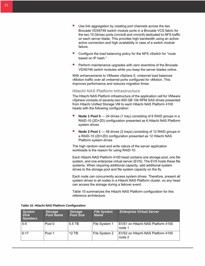
T
Use link aggregation by creating port channels across the two Brocade VDX6746 switch module ports in a Brocade VCS fabric for the two 10 Gb/sec ports (vmnic8 and vmnic9) dedicated to NFS traffic on each server blade, This provides high bandwidth using an active-active connection and high availability in case of a switch module failure.
Configure the load balancing policy for the NFS vSwitch for “route based on IP hash.”
Perform maintenance upgrades with zero downtime of the Brocade VDX6746 switch modules while you keep the server blades online.
With enhancements to VMware vSphere 5, vmkernel load balances vMotion traffic over all vmkernel ports configured for vMotion. This improves performance and reduces migration times.
Hitachi NAS Platform InfrastructureThe Hitachi NAS Platform infrastructure of the application cell for VMware vSphere consists of seventy-two 600 GB 10k RPM SAS drives presented from Hitachi Unified Storage VM to each Hitachi NAS Platform 4100 heads with the following configuration:
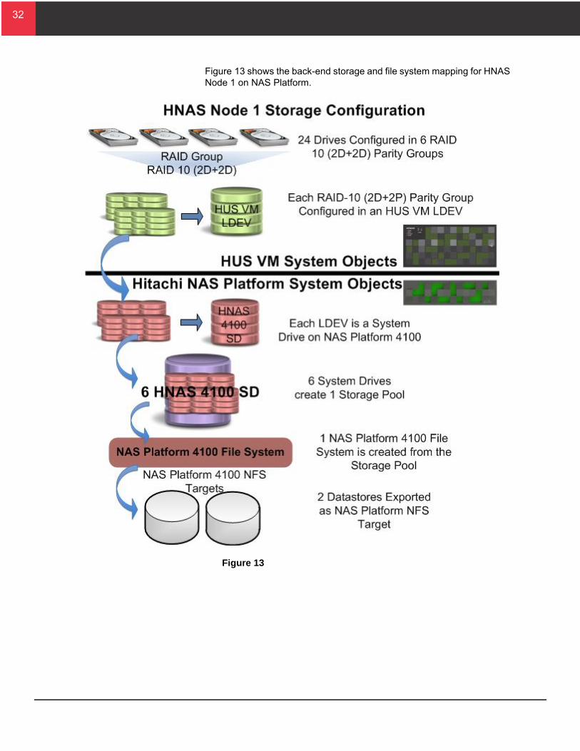
Node 1 Pool 0 — 24 drives (1 tray) consisting of 6 RAID groups in a RAID-10 (2D+2D) configuration presented as 6 Hitachi NAS Platform system drives
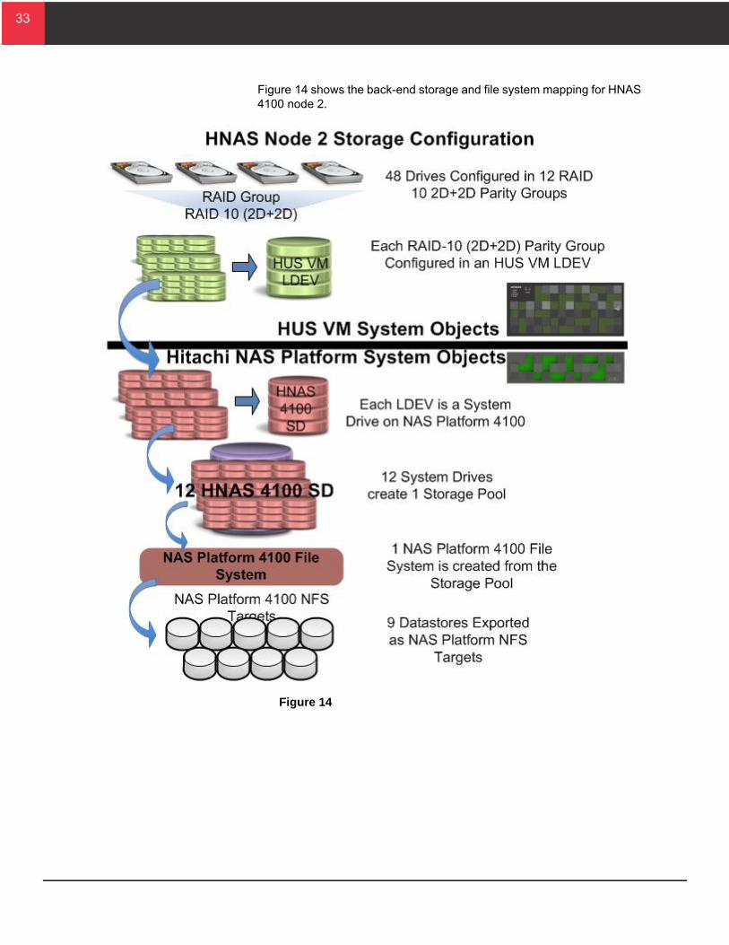
Node 2 Pool 1 — 48 drives (2 trays) consisting of 12 RAID groups in a RAID-10 (2D+2D) configuration presented as 12 Hitachi NAS Platform system drives
The high random read and write nature of the server application workloads is the reason for using RAID-10.
Each Hitachi NAS Platform 4100 head contains one storage pool, one file system, and one enterprise virtual server (EVS). The EVS hosts these file systems. When requiring additional capacity, add additional system drives to the storage pool and file system capacity on the fly.
Each node can concurrently access system drives. Therefore, present all system drives to all nodes in a Hitachi NAS Platform cluster, so any head can access the storage during a failover event.
Table 10 summarizes the Hitachi NAS Platform configuration for this reference architecture.
able 10. Hitachi NAS Platform Configuration
System Disk Numbers
Storage Pool Name
Storage Pool Size
File System Name
Enterprise Virtual Server
0-5 Pool 0 5.5 TB File System 1 EVS1 on Hitachi NAS Platform 4100 node 1
6-17 Pool 1 12 TB File System 2 EVS2 on Hitachi NAS Platform 4100 node 2
32
32
Figure 13 shows the back-end storage and file system mapping for HNAS Node 1 on NAS Platform.
Figure 13
33
33
Figure 14 shows the back-end storage and file system mapping for HNAS 4100 node 2.
Figure 14
34
34
Configure Hitachi NAS Platform 4100 with the following best practice recommendations:
Disable the read ahead cache on the Hitachi NAS Platform 4100 cluster.
Use a 4 KB file system block size with VMware environments.
Install and use VMware VAAI for NAS adapter for Hitachi NAS Platform.
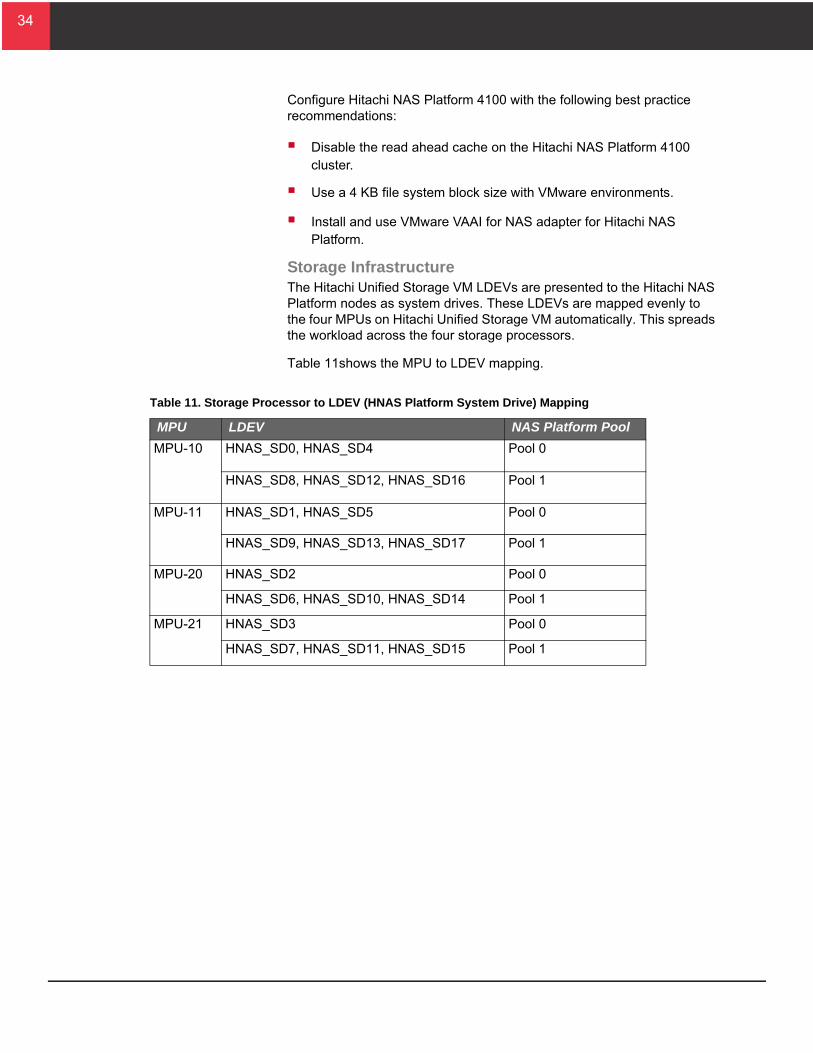
Storage InfrastructureThe Hitachi Unified Storage VM LDEVs are presented to the Hitachi NAS Platform nodes as system drives. These LDEVs are mapped evenly to the four MPUs on Hitachi Unified Storage VM automatically. This spreads the workload across the four storage processors.
Table 11shows the MPU to LDEV mapping.
Table 11. Storage Processor to LDEV (HNAS Platform System Drive) Mapping
MPU LDEV NAS Platform Pool
MPU-10 HNAS_SD0, HNAS_SD4 Pool 0
HNAS_SD8, HNAS_SD12, HNAS_SD16 Pool 1
MPU-11 HNAS_SD1, HNAS_SD5 Pool 0
HNAS_SD9, HNAS_SD13, HNAS_SD17 Pool 1
MPU-20 HNAS_SD2 Pool 0
HNAS_SD6, HNAS_SD10, HNAS_SD14 Pool 1
MPU-21 HNAS_SD3 Pool 0
HNAS_SD7, HNAS_SD11, HNAS_SD15 Pool 1
35
35
T
Engineering ValidationThis is the test methodology used to validate this reference architecture and the results of the testing. These tests demonstrated the maximum utilization of the reference architecture.
The purpose of the tests was to determine maximum loads that the solution could support and still maintain an acceptable application performance.
Test MethodologyTesting of the core components of this Hitachi Unified Compute Platform Select for VMware vSphere reference architecture solution validated its performance and design. Testing validated a mixed workload of the following:
Email messages
Web pages
Online transaction processing (OLTP)
The workload was grouped into a tile-based system to measure application performance and scalability. Each tile contained mixed workloads that stress critical compute and storage resources. These workloads represent a general purpose data center environment for VMware vSphere.
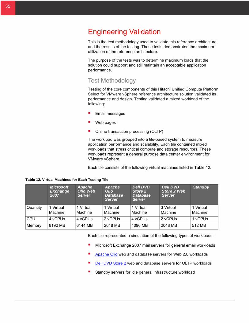
Each tile consists of the following virtual machines listed in Table 12.
Each tile represented a simulation of the following types of workloads:
Microsoft Exchange 2007 mail servers for general email workloads
Apache Olio web and database servers for Web 2.0 workloads
Dell DVD Store 2 web and database servers for OLTP workloads
Standby servers for idle general infrastructure workload
able 12. Virtual Machines for Each Testing Tile
Microsoft Exchange 2007
Apache Olio Web Server
Apache Olio Database Server
Dell DVD Store 2 Database Server
Dell DVD Store 2 Web Server
Standby
Quantity 1 Virtual Machine
1 Virtual Machine
1 Virtual Machine
1 Virtual Machine
3 Virtual Machine
1 Virtual Machine
CPU 4 vCPUs 4 vCPUs 2 vCPUs 4 vCPUs 2 vCPUs 1 vCPUs
Memory 8192 MB 6144 MB 2048 MB 4096 MB 2048 MB 512 MB
36
36
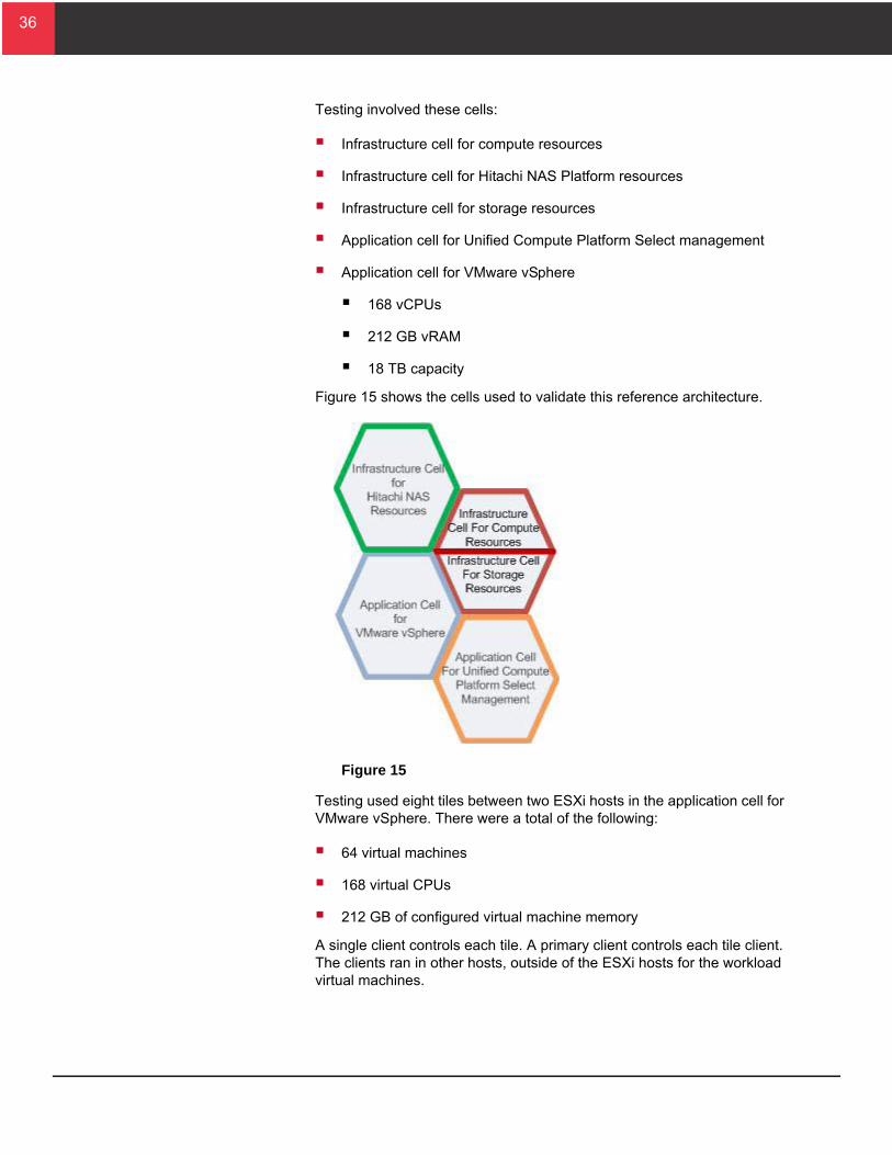
Testing involved these cells:
Infrastructure cell for compute resources
Infrastructure cell for Hitachi NAS Platform resources
Infrastructure cell for storage resources
Application cell for Unified Compute Platform Select management
Application cell for VMware vSphere
168 vCPUs
212 GB vRAM
18 TB capacity
Figure 15 shows the cells used to validate this reference architecture.
Figure 15
Testing used eight tiles between two ESXi hosts in the application cell for VMware vSphere. There were a total of the following:
64 virtual machines
168 virtual CPUs
212 GB of configured virtual machine memory
A single client controls each tile. A primary client controls each tile client. The clients ran in other hosts, outside of the ESXi hosts for the workload virtual machines.
37
37
T
T
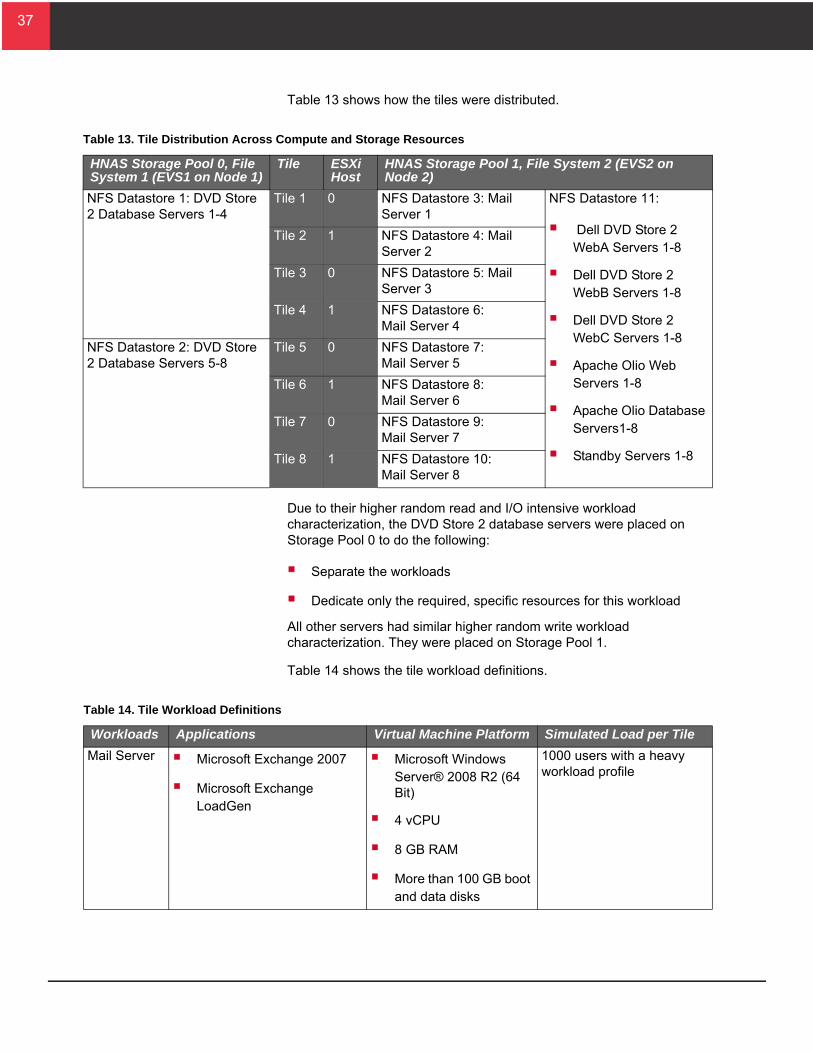
Table 13 shows how the tiles were distributed.
Due to their higher random read and I/O intensive workload characterization, the DVD Store 2 database servers were placed on Storage Pool 0 to do the following:
Separate the workloads
Dedicate only the required, specific resources for this workload
All other servers had similar higher random write workload characterization. They were placed on Storage Pool 1.
Table 14 shows the tile workload definitions.
able 13. Tile Distribution Across Compute and Storage Resources
HNAS Storage Pool 0, File System 1 (EVS1 on Node 1)
Tile ESXi Host
HNAS Storage Pool 1, File System 2 (EVS2 on Node 2)
NFS Datastore 1: DVD Store 2 Database Servers 1-4
Tile 1 0 NFS Datastore 3: Mail Server 1
NFS Datastore 11:
Dell DVD Store 2 WebA Servers 1-8
Dell DVD Store 2 WebB Servers 1-8
Dell DVD Store 2 WebC Servers 1-8
Apache Olio Web Servers 1-8
Apache Olio Database Servers1-8
Standby Servers 1-8
Tile 2 1 NFS Datastore 4: Mail Server 2
Tile 3 0 NFS Datastore 5: Mail Server 3
Tile 4 1 NFS Datastore 6:Mail Server 4
NFS Datastore 2: DVD Store 2 Database Servers 5-8
Tile 5 0 NFS Datastore 7:Mail Server 5
Tile 6 1 NFS Datastore 8:Mail Server 6
Tile 7 0 NFS Datastore 9:Mail Server 7
Tile 8 1 NFS Datastore 10:Mail Server 8
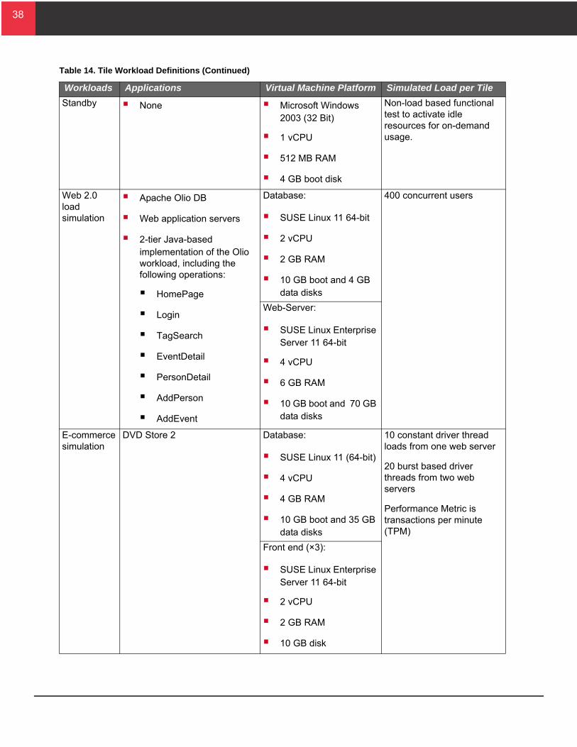
able 14. Tile Workload Definitions
Workloads Applications Virtual Machine Platform Simulated Load per Tile
Mail Server Microsoft Exchange 2007
Microsoft Exchange LoadGen
Microsoft Windows Server® 2008 R2 (64 Bit)
4 vCPU
8 GB RAM
More than 100 GB boot and data disks
1000 users with a heavy workload profile
38
38
T
Standby None Microsoft Windows 2003 (32 Bit)
1 vCPU
512 MB RAM
4 GB boot disk
Non-load based functional test to activate idle resources for on-demand usage.
Web 2.0 load simulation
Apache Olio DB
Web application servers
2-tier Java-based implementation of the Olio workload, including the following operations:
HomePage
Login
TagSearch
EventDetail
PersonDetail
AddPerson
AddEvent
Database:
SUSE Linux 11 64-bit
2 vCPU
2 GB RAM
10 GB boot and 4 GB data disks
400 concurrent users
Web-Server:
SUSE Linux Enterprise Server 11 64-bit
4 vCPU
6 GB RAM
10 GB boot and 70 GB data disks
E-commerce simulation
DVD Store 2 Database:
SUSE Linux 11 (64-bit)
4 vCPU
4 GB RAM
10 GB boot and 35 GB data disks
10 constant driver thread loads from one web server
20 burst based driver threads from two web servers
Performance Metric is transactions per minute (TPM)
Front end (×3):
SUSE Linux Enterprise Server 11 64-bit
2 vCPU
2 GB RAM
10 GB disk
able 14. Tile Workload Definitions (Continued)
Workloads Applications Virtual Machine Platform Simulated Load per Tile
39
39
Compute InfrastructureMultiple performance metrics were collected from the ESXi hypervisor during the test.
With hyper-threading enabled on the two 8-Core Intel Xeon E5-2680 processors, 32 logical CPUs are available for each host. There were 32 virtual machines configured with 84 virtual CPUs which ran on each server blade.
Each 520HA1 server blade contained 96 GB of RAM. The 32 virtual machines were configured with a total of 106 GB of vRAM on each blade. Over commitment of memory allocation was 10 GB.
Guest operating system metrics for each type of server were also collected during the workload runs.
Hitachi NAS Platform InfrastructureMultiple performance metrics were collected from Hitachi NAS Platform during the test. Analysis of the metrics from the Hitachi NAS Platform 4100 heads was performed to show the following:
System load was at consistently optimal levels
Impact of cluster node failover
Hitachi NAS Platform Infrastructure (High Availability)High availability of the Hitachi NAS Platform cluster was tested during a separate test run. The following actions were performed on Node 2 to simulate failures and to ensure that a single node could handle the general server application workloads:
All four 10 Gb/sec Ethernet connections were disconnected from Node 2.
EVS migration from Node 2 to Node 1.
Reboot of Node 2.
Storage InfrastructureMultiple performance metrics from Hitachi Unified Storage VM were collected during the test. Analysis of the metrics from the Hitachi Unified Storage VM controllers was performed to verify the following:
Physical disks were not saturated
Storage processor and cache were not overwhelmed
LDEVs (presented as Hitachi NAS Platform system drives) performance
40
40
Application PerformanceTesting measured application performance using the following metrics:
Application workload throughput
Application workload latency was below 500 msec with the storage-optimized configuration described in Storage Infrastructure.
Test ResultsThese are the test results for the Application Cell for VMware vSphere environment operating in a steady state condition with an 8-tile workload.
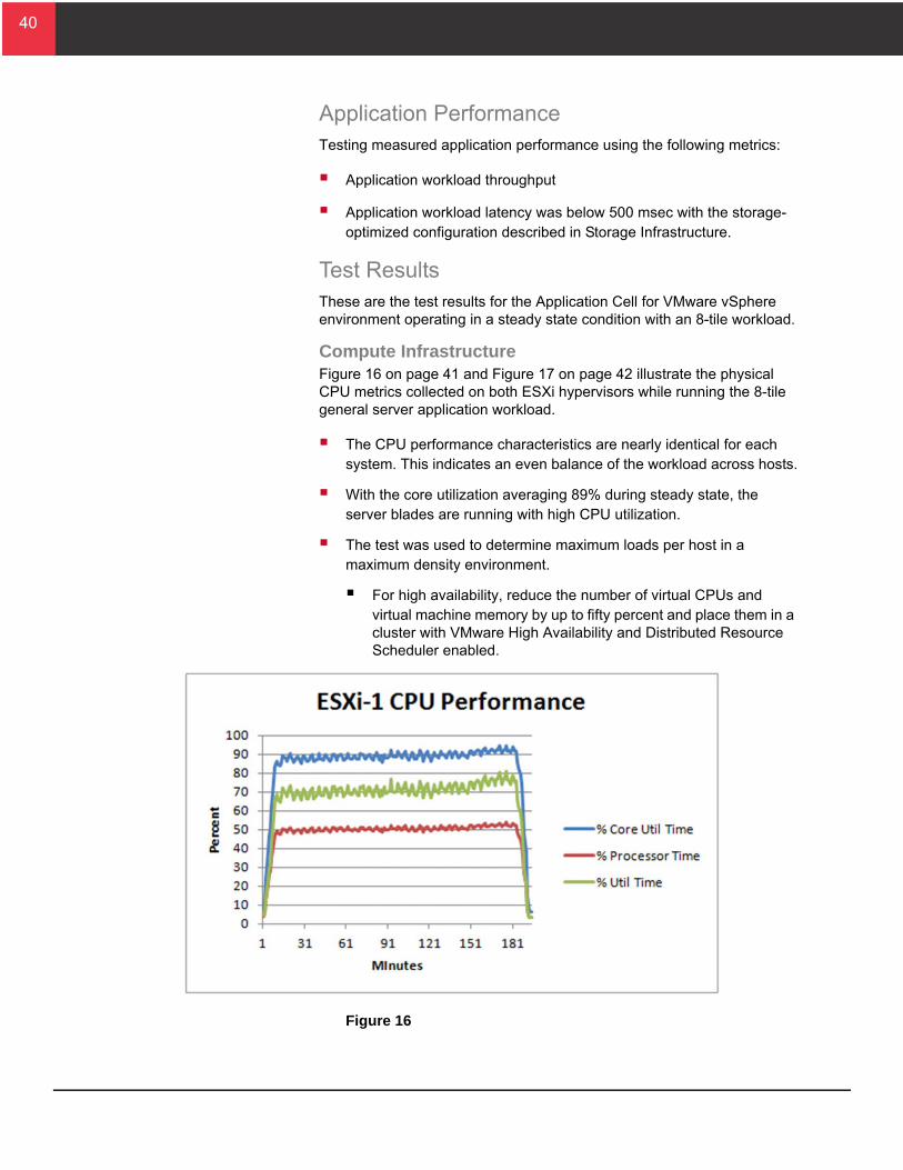
Compute InfrastructureFigure 16 on page 41 and Figure 17 on page 42 illustrate the physical CPU metrics collected on both ESXi hypervisors while running the 8-tile general server application workload.
The CPU performance characteristics are nearly identical for each system. This indicates an even balance of the workload across hosts.
With the core utilization averaging 89% during steady state, the server blades are running with high CPU utilization.
The test was used to determine maximum loads per host in a maximum density environment.
For high availability, reduce the number of virtual CPUs and virtual machine memory by up to fifty percent and place them in a cluster with VMware High Availability and Distributed Resource Scheduler enabled.
Figure 16
41
41
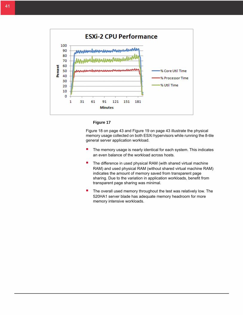
Figure 17
Figure 18 on page 43 and Figure 19 on page 43 illustrate the physical memory usage collected on both ESXi hypervisors while running the 8-tile general server application workload.
The memory usage is nearly identical for each system. This indicates an even balance of the workload across hosts.
The difference in used physical RAM (with shared virtual machine RAM) and used physical RAM (without shared virtual machine RAM) indicates the amount of memory saved from transparent page sharing. Due to the variation in application workloads, benefit from transparent page sharing was minimal.
The overall used memory throughout the test was relatively low. The 520HA1 server blade has adequate memory headroom for more memory intensive workloads.
42
42
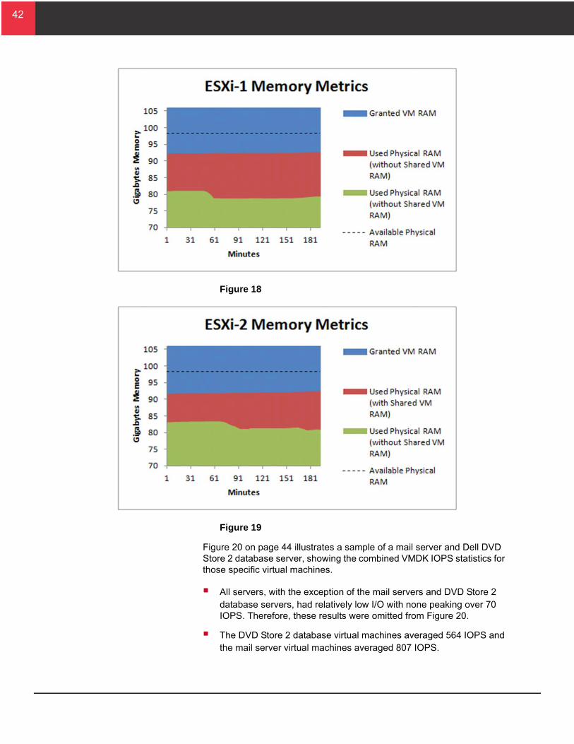
Figure 18
Figure 19
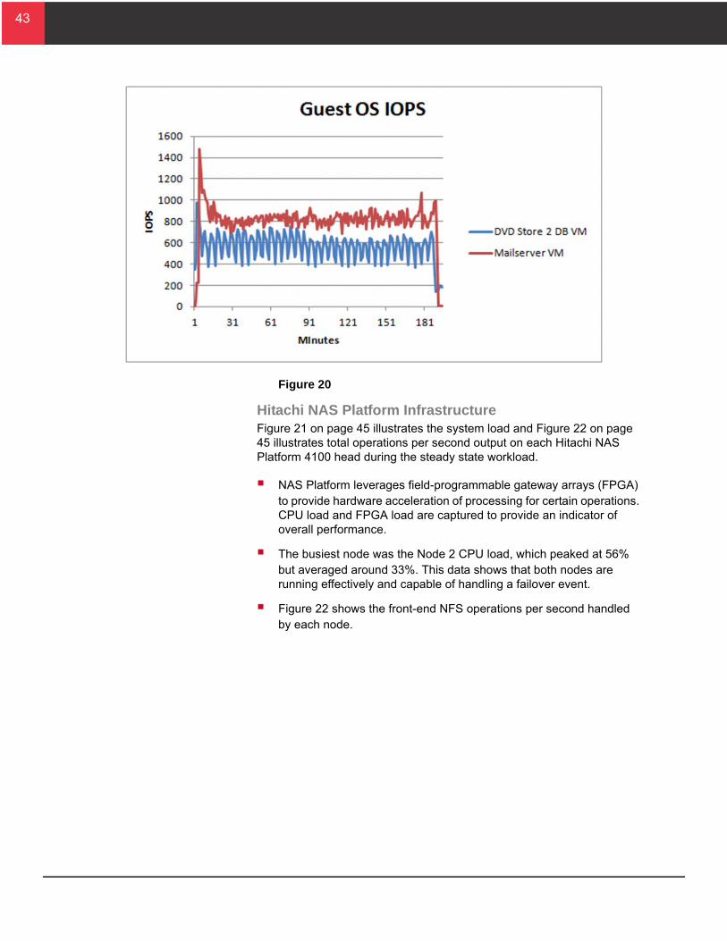
Figure 20 on page 44 illustrates a sample of a mail server and Dell DVD Store 2 database server, showing the combined VMDK IOPS statistics for those specific virtual machines.
All servers, with the exception of the mail servers and DVD Store 2 database servers, had relatively low I/O with none peaking over 70 IOPS. Therefore, these results were omitted from Figure 20.
The DVD Store 2 database virtual machines averaged 564 IOPS and the mail server virtual machines averaged 807 IOPS.
43
43
Figure 20
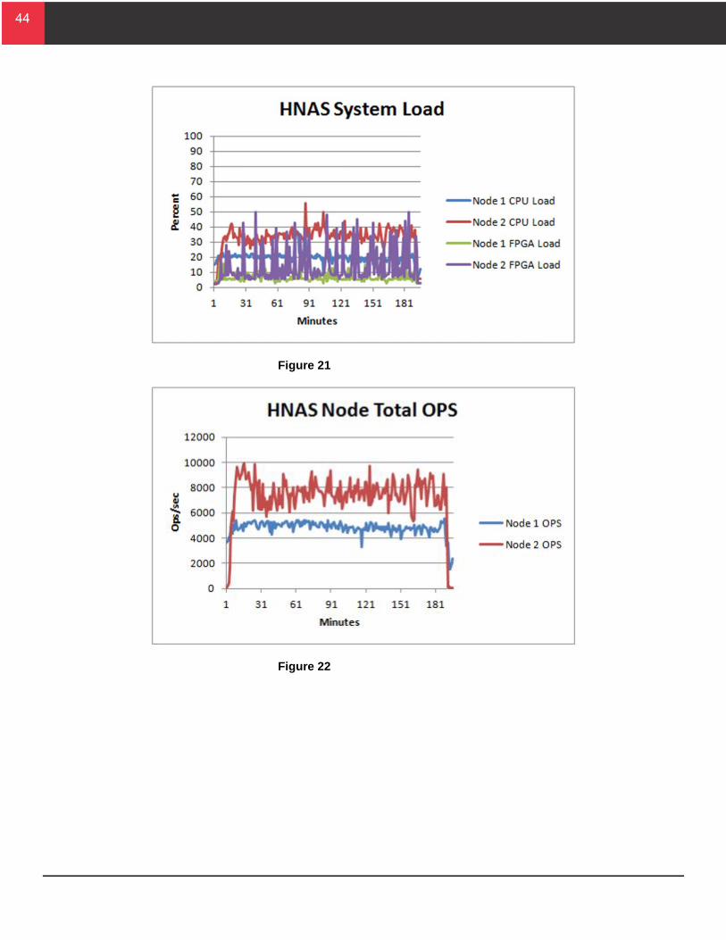
Hitachi NAS Platform InfrastructureFigure 21 on page 45 illustrates the system load and Figure 22 on page 45 illustrates total operations per second output on each Hitachi NAS Platform 4100 head during the steady state workload.
NAS Platform leverages field-programmable gateway arrays (FPGA) to provide hardware acceleration of processing for certain operations. CPU load and FPGA load are captured to provide an indicator of overall performance.
The busiest node was the Node 2 CPU load, which peaked at 56% but averaged around 33%. This data shows that both nodes are running effectively and capable of handling a failover event.
Figure 22 shows the front-end NFS operations per second handled by each node.
44
44
Figure 21
Figure 22
45
45
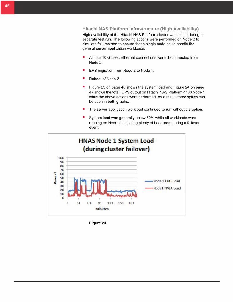
Hitachi NAS Platform Infrastructure (High Availability)High availability of the Hitachi NAS Platform cluster was tested during a separate test run. The following actions were performed on Node 2 to simulate failures and to ensure that a single node could handle the general server application workloads:
All four 10 Gb/sec Ethernet connections were disconnected from Node 2.
EVS migration from Node 2 to Node 1.
Reboot of Node 2.
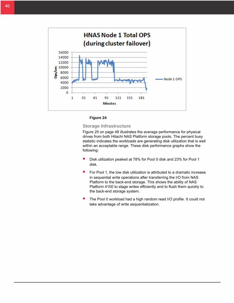
Figure 23 on page 46 shows the system load and Figure 24 on page 47 shows the total IOPS output on Hitachi NAS Platform 4100 Node 1 while the above actions were performed. As a result, three spikes can be seen in both graphs.
The server application workload continued to run without disruption.
System load was generally below 50% while all workloads were running on Node 1 indicating plenty of headroom during a failover event.
Figure 23
46
46
Figure 24
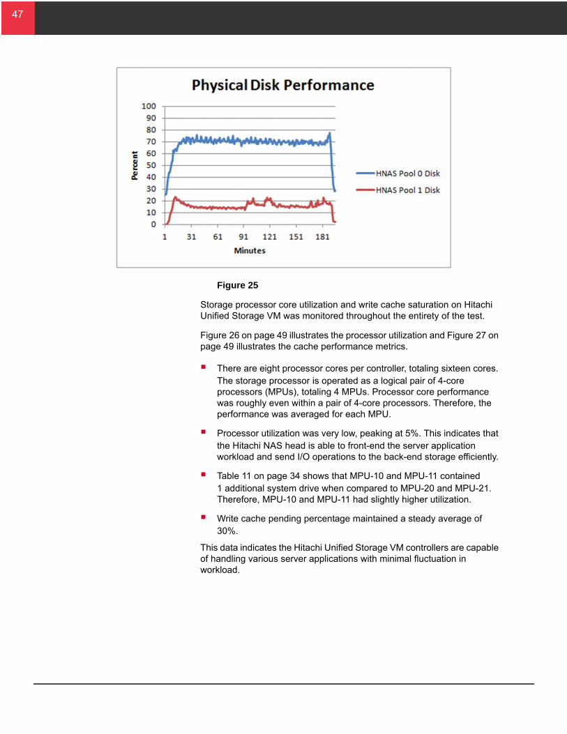
Storage InfrastructureFigure 25 on page 48 illustrates the average performance for physical drives from both Hitachi NAS Platform storage pools. The percent busy statistic indicates the workloads are generating disk utilization that is well within an acceptable range. These disk performance graphs show the following:
Disk utilization peaked at 78% for Pool 0 disk and 23% for Pool 1 disk.
For Pool 1, the low disk utilization is attributed to a dramatic increase in sequential write operations after transferring the I/O from NAS Platform to the back-end storage. This shows the ability of NAS Platform 4100 to stage writes efficiently and to flush them quickly to the back-end storage system.
The Pool 0 workload had a high random read I/O profile. It could not take advantage of write sequentialization.
47
47
Figure 25
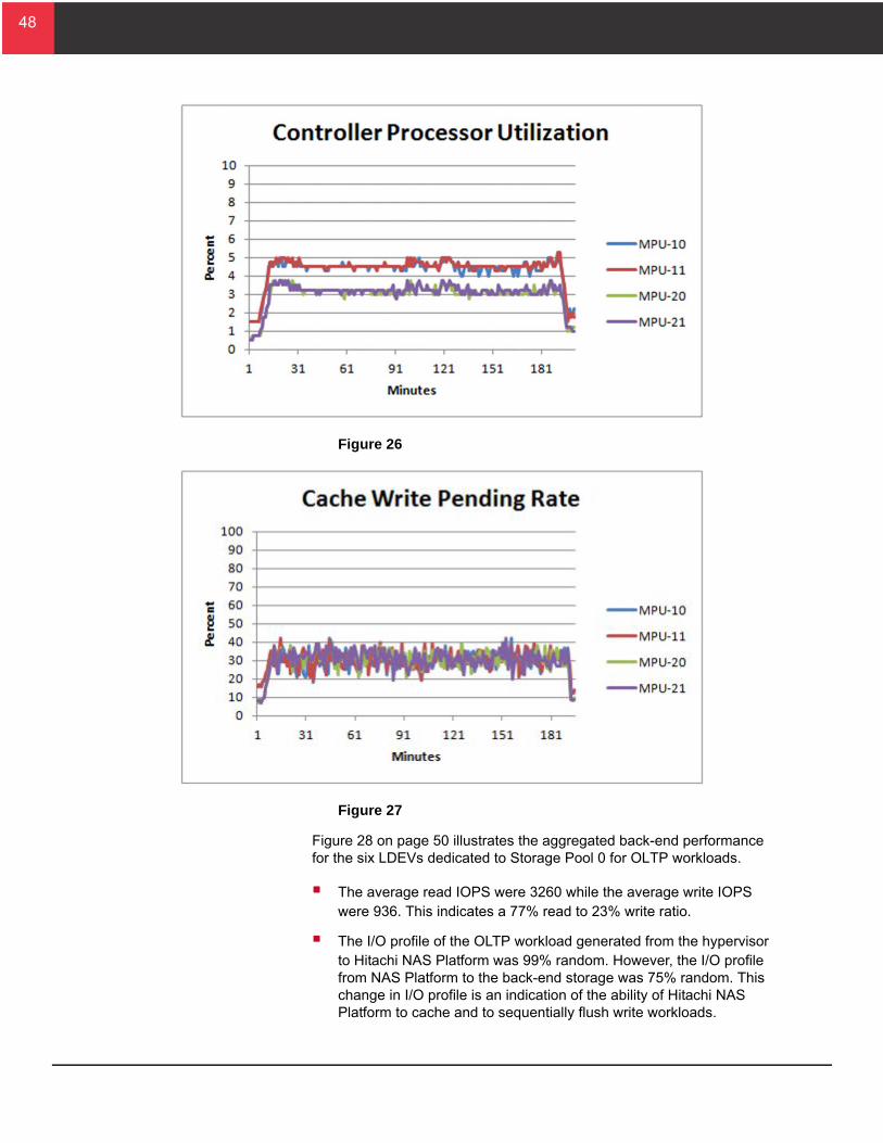
Storage processor core utilization and write cache saturation on Hitachi Unified Storage VM was monitored throughout the entirety of the test.
Figure 26 on page 49 illustrates the processor utilization and Figure 27 on page 49 illustrates the cache performance metrics.
There are eight processor cores per controller, totaling sixteen cores. The storage processor is operated as a logical pair of 4-core processors (MPUs), totaling 4 MPUs. Processor core performance was roughly even within a pair of 4-core processors. Therefore, the performance was averaged for each MPU.
Processor utilization was very low, peaking at 5%. This indicates that the Hitachi NAS head is able to front-end the server application workload and send I/O operations to the back-end storage efficiently.
Table 11 on page 34 shows that MPU-10 and MPU-11 contained 1 additional system drive when compared to MPU-20 and MPU-21. Therefore, MPU-10 and MPU-11 had slightly higher utilization.
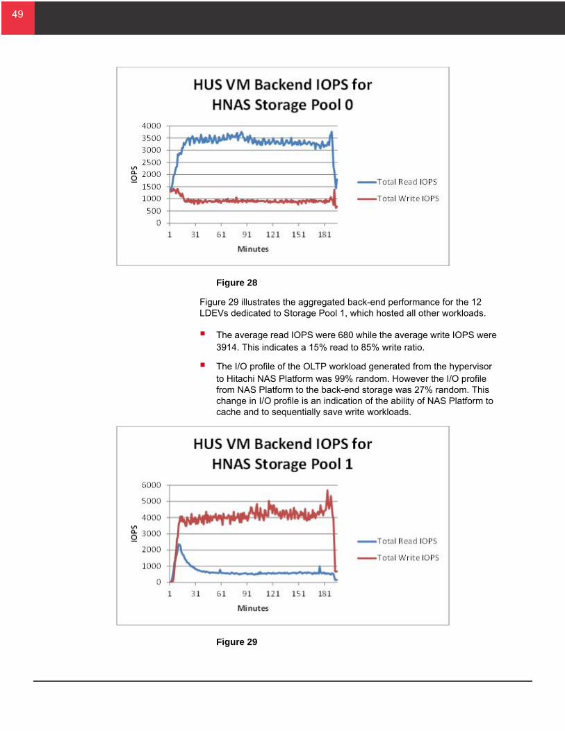
Write cache pending percentage maintained a steady average of 30%.
This data indicates the Hitachi Unified Storage VM controllers are capable of handling various server applications with minimal fluctuation in workload.
48
48
Figure 26
Figure 27
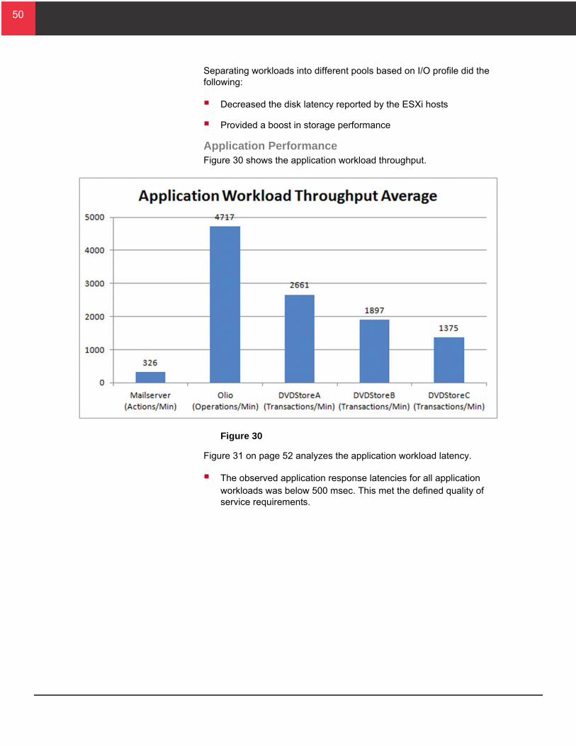
Figure 28 on page 50 illustrates the aggregated back-end performance for the six LDEVs dedicated to Storage Pool 0 for OLTP workloads.
The average read IOPS were 3260 while the average write IOPS were 936. This indicates a 77% read to 23% write ratio.
The I/O profile of the OLTP workload generated from the hypervisor to Hitachi NAS Platform was 99% random. However, the I/O profile from NAS Platform to the back-end storage was 75% random. This change in I/O profile is an indication of the ability of Hitachi NAS Platform to cache and to sequentially flush write workloads.
49
49
Figure 28
Figure 29 illustrates the aggregated back-end performance for the 12 LDEVs dedicated to Storage Pool 1, which hosted all other workloads.
The average read IOPS were 680 while the average write IOPS were 3914. This indicates a 15% read to 85% write ratio.
The I/O profile of the OLTP workload generated from the hypervisor to Hitachi NAS Platform was 99% random. However the I/O profile from NAS Platform to the back-end storage was 27% random. This change in I/O profile is an indication of the ability of NAS Platform to cache and to sequentially save write workloads.
Figure 29
50
50
Separating workloads into different pools based on I/O profile did the following:
Decreased the disk latency reported by the ESXi hosts
Provided a boost in storage performance
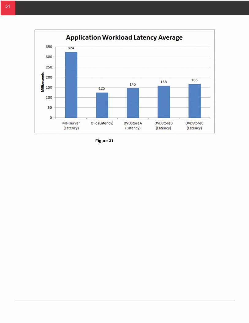
Application PerformanceFigure 30 shows the application workload throughput.
Figure 30
Figure 31 on page 52 analyzes the application workload latency.
The observed application response latencies for all application workloads was below 500 msec. This met the defined quality of service requirements.
51
51
Figure 31
52
52
ConclusionValidation testing proves that this Hitachi Unified Compute Platform Select for VMware vSphere reference architecture provides a build-as-you-go model using Hitachi Unified Storage VM, Hitachi NAS Platform 4100, and Hitachi Compute Blade 500. The modular design, using a cell architecture, permits you to start your implementation with an environment for modest needs. Later, you have the flexibility to scale out the environment as your IT needs grow.

53
53
For More InformationHitachi Data Systems Global Services offers experienced storage consultants, proven methodologies and a comprehensive services portfolio to assist you in implementing Hitachi products and solutions in your environment. For more information, see the Hitachi Data Systems Global Services website.
Live and recorded product demonstrations are available for many Hitachi products. To schedule a live demonstration, contact a sales representative. To view a recorded demonstration, see the Hitachi Data Systems Corporate Resources website. Click the Product Demos tab for a list of available recorded demonstrations.
Hitachi Data Systems Academy provides best-in-class training on Hitachi products, technology, solutions and certifications. Hitachi Data Systems Academy delivers on-demand web-based training (WBT), classroom-based instructor-led training (ILT) and virtual instructor-led training (vILT) courses. For more information, see the Hitachi Data Systems Services Education website.
For more information about Hitachi products and services, contact your sales representative or channel partner or visit the Hitachi Data Systems website.
Corporate Headquarters2845 Lafayette Street, Santa Clara, California 95050-2627 USAwww.HDS.com
Regional Contact InformationAmericas: +1 408 970 1000 or [email protected], Middle East and Africa: +44 (0) 1753 618000 or [email protected] Asia-Pacific: +852 3189 7900 or [email protected]
© Hitachi Data Systems Corporation 2013. All Rights Reserved. HITACHI is a trademark or registered trademark of Hitachi, Ltd. Innovate With Information is a trademark or registered trademark of Hitachi Data Systems Corporation. Microsoft, SQL Server, Active Directory, and Windows Server are trademarks or registered trademarks of Microsoft Corporation. All other trademarks, service marks, and company names are properties of their respective owners.
Notice: This document is for informational purposes only, and does not set forth any warranty, expressed or implied, concerning any equipment or service offered or to be offered by Hitachi Data Systems Corporation.
AS-238-01, August 2013