Embed Size (px)
Citation preview

QMP 7.1 D/F
Channabasaveshwara Institute of Technology (Affiliated to VTU, Belgaum & Approved by AICTE, New Delhi)
(NAAC Accredited & ISO 9001:2015 Certified Institution) NH 206 (B.H. Road), Gubbi, Tumkur – 572 216. Karnataka.
Department of Mechanical Engineering
LAB MANUAL (2018-19)
FOUNDRY AND FORGING LABORATORY (17MEL38A/48A)
III/IV Semester
Name:__________________________________________
U.S.N:__________________________________________
Batch:________________ Section:________________

QMP 7.1 D/F
Channabasaveshwara Institute of Technology (Affiliated to VTU, Belgaum & Approved by AICTE, New Delhi)
(NAAC Accredited & ISO 9001:2015 Certified Institution) NH 206 (B.H. Road), Gubbi, Tumkur – 572 216. Karnataka.
Department of Mechanical Engineering
FOUNDRY AND FORGING LABORATORY
2018-19
Prepared by: Approved by:
Mr. Shreenivas P Patil Mr. Giridhar S Kulkarni Assistant Professor Professor and Head,
Dept. of Mechanical Engineering Dept. of Mechanical Engineering

Channabasaveshwara Institute of Technology(Affiliated to VTU, Belgaum & Approved by AICTE, New Delhi)
(NAAC Accredited & ISO 9001:2015 Certified Institution) NH 206 (B.H. Road), Gubbi, Tumkur
SL.NO 01 Vision and Mission
02 Syllabus
03 Objectives and Outcomes
04 Safety measures
05 Foundry and Forging
06 List of Experiments
07 Lab Lesson Plan
TESTING OF MOULD AND CORE SAND
Expt. No
Properties of Moulding sand
01 Compression strength test for moulding sand
02 Shear strength test for moulding sand
03 Tensile strength test of core sand04 Permeability test
05 Core hardness and mould hardness test
06 Sieve analysis to find grain fineness number of base sand
07 Clay content test
Introduction to foundry
01 Solid Pattern
02 Hand Cutting
03 Self Cored Pattern
04 Stepped Cone Pulley With Core Print
QMP 7.1 D/FChannabasaveshwara Institute of Technology
(Affiliated to VTU, Belgaum & Approved by AICTE, New Delhi) NAAC Accredited & ISO 9001:2015 Certified Institution)
NH 206 (B.H. Road), Gubbi, Tumkur – 572 216. Karnataka.
CONTENTS
Subject of college and department
Objectives and Outcomes of the lab
Foundry and Forging Lab Layout
PART-A
TESTING OF MOULD AND CORE SAND
Title of the Experiment
Properties of Moulding sand
Compression strength test for moulding sand
Shear strength test for moulding sand
strength test of core sand
Core hardness and mould hardness test
Sieve analysis to find grain fineness number of base sand
PART-B
FOUNDRY
Introduction to foundry
Stepped Cone Pulley With Core Print
QMP 7.1 D/F Channabasaveshwara Institute of Technology
Page No I
II- III
IV
V
VI
VII
VIII-IX
Page No
3-5
6-9
10-12
13-17
18-21
22-23
24-27
28-29
31-46
48-49
50-51
52-53
54-55

05 Split Pattern with Two Halves 56-57
06 Loose Piece Pattern [additional] 58-59
Estimation of material cost 60-63
PART-C
FORGING
Forging Theory 67-79
01 Hexagonal Allen key 80-81
02 Square section nail 82-83
03 T-bolt (hexagonal headed bolt) 84
Viva question with answers 85-89
References 90

Channabasaveshwara Institute of Technology(Affiliated to VTU, Belgaum & Approved by AICTE, New Delhi)
(NAAC Accredited & ISO 9001:2015 Certified Institution) NH 206 (B.H. Road), Gubbi, Tumkur
To create centres of excellence in education and to serve the society by enhancing the quality of life through value based professional leadership.
To provide high quality technical and professionally relevant education in a diverse learnenvironment.
• To provide the values that prepare students to lead their lives with personal integrity,
professional ethics and civic responsibility in a global society.
• To prepare the next generation of skilled professionals to successfully compete in t
global market.
• To promote a campus environment that welcomes and honors women and men of all races,
creeds and cultures, values and intellectual curiosity, pursuit of knowledge and academic
integrity and freedom.
• To offer a wide variety of off
groups.
• To stimulate collaborative efforts with industry, universities, government and professional
societies.
• To facilitate public understanding of technical issues and achieve excellence in the
of the institute.
To create state of the art learning environment to nurture the learning, blending human values, academic professionalism and research process in the field of mechanical engineering for the betterment of society.
The mission of the department is to provide requisite foundation to our students in Mechanical Engineering provide cutting edge laboratory resources to bridge the gap between theoretical and practical concepts provideperiodic industrial visits enhance our students skill set and to make them industry ready by systematic skill development program.
Channabasaveshwara Institute of Technology(Affiliated to VTU, Belgaum & Approved by AICTE, New Delhi)
NAAC Accredited & ISO 9001:2015 Certified Institution) NH 206 (B.H. Road), Gubbi, Tumkur – 572 216. Karnataka.
College Vision To create centres of excellence in education and to serve the society by enhancing the quality of life through value based professional leadership.
College Mission
To provide high quality technical and professionally relevant education in a diverse learn
To provide the values that prepare students to lead their lives with personal integrity,
professional ethics and civic responsibility in a global society.
To prepare the next generation of skilled professionals to successfully compete in t
To promote a campus environment that welcomes and honors women and men of all races,
creeds and cultures, values and intellectual curiosity, pursuit of knowledge and academic
To offer a wide variety of off-campus education and training programmes to individuals and
To stimulate collaborative efforts with industry, universities, government and professional
To facilitate public understanding of technical issues and achieve excellence in the
Vision of the Department
To create state of the art learning environment to nurture the learning, blending human values, academic professionalism and research process in the field of mechanical engineering
Mission of the Department The mission of the department is to provide requisite foundation to our students in Mechanical Engineering provide cutting edge laboratory resources to bridge the gap between theoretical and practical concepts provide exposure to various mechanical industries through periodic industrial visits enhance our students skill set and to make them industry ready by systematic skill development program.
I
Channabasaveshwara Institute of Technology NAAC Accredited & ISO 9001:2015 Certified Institution)
To create centres of excellence in education and to serve the society by enhancing the quality
To provide high quality technical and professionally relevant education in a diverse learning
To provide the values that prepare students to lead their lives with personal integrity,
To prepare the next generation of skilled professionals to successfully compete in the diverse
To promote a campus environment that welcomes and honors women and men of all races,
creeds and cultures, values and intellectual curiosity, pursuit of knowledge and academic
ampus education and training programmes to individuals and
To stimulate collaborative efforts with industry, universities, government and professional
To facilitate public understanding of technical issues and achieve excellence in the operations
To create state of the art learning environment to nurture the learning, blending human values, academic professionalism and research process in the field of mechanical engineering
The mission of the department is to provide requisite foundation to our students in Mechanical Engineering provide cutting edge laboratory resources to bridge the gap between
exposure to various mechanical industries through periodic industrial visits enhance our students skill set and to make them industry ready by

QMP 7.1 D/F Channabasaveshwara Institute of Technology
(Affiliated to VTU, Belgaum & Approved by AICTE, New Delhi) (NAAC Accredited & ISO 9001:2015 Certified Institution)
NH 206 (B.H. Road), Gubbi, Tumkur – 572 216. Karnataka.
Syllabus
FOUNDRY AND FORGING LAB B.E, IV Semester, Mechanical Engineering
[As per Choice Based Credit System (CBCS) scheme] Course Code 17MEL38A / 48A CIE Marks 40
Number of Lecture Hours/Week
03 (1 Hour Instruction + 2 Hours Laboratory)
SEE Marks 60
RBT Levels L1, L2, L3 Exam Hours 03 Credits – 02
COURSE OBJECTIVES:
� To provide an insight into different sand preparation and foundry equipment’s.
� To provide an insight into different forging tools and equipment’s.
� To provide training to students to enhance their practical skills.
� To practically demonstrate precautions to be taken during casting and hot working.
� To develop team qualities and ethical principles.
PART A 1. Testing of Molding sand and Core sand Preparation of sand specimens and conduction of the following tests: 1. Compression, Shear and Tensile tests on Universal Sand Testing Machine. 2. Permeability test 3. Sieve Analysis to find Grain Fineness Number (GFN) of Base Sand 4. Clay content determination in Base Sand.
PART B 2. Foundry Practice 1. Use of foundry tools and other equipment’s. 2. Preparation of molding sand mixture. 3. Preparation of green sand molds using two molding boxes kept ready for pouring.
• Using patterns (Single piece pattern and Split pattern) • Without patterns. • Incorporating core in the mold. (Core boxes). • Preparation of one casting (Aluminium or cast iron-Demonstration only)
II

PART C
3. Forging Operations: Use of forging tools and other equipment’s
• Calculation of length of the raw material required to prepare the model considering scale loss. • Preparing minimum three forged models involving upsetting, drawing and bending
operations. • Demonstration of forging model using Power Hammer.
COURSE OUTCOMES
Students will be able to � Demonstrate various skills of sand preparation, molding.
� Demonstrate various skills of forging operations.
� Work as a team keeping up ethical principles.
Scheme of Examination: One question is to be set from Part-A 30 Marks One question is to be set from either Part-B or Part-C 50 Marks Viva – Voce 20 Marks _________________________________________________________________ Total 100 Marks
III
Channabasaveshwara Institute of Technology(Affiliated to VTU, Belgaum & Approved by AICTE, New Delhi)
(NAAC Accredited & ISO 9001:2015 Certified Institution) NH 206 (B.H. Road), Gubbi, Tumkur
COURSE OBJECTIVES:
� To provide an insight into different sand preparation and foundry equipment’s.
� To provide an insight into different forging tools and equipment’s.
� To provide training to students to enhance their practical skills.
� To practically demonstrate pr
� To develop team qualities and ethical principles.
COURSE OUTCOMES:
Students will be able to
� Demonstrate various skills of sand preparation, molding.
� Demonstrate various skills of forging
� Work as a team keeping up ethical principles.
Channabasaveshwara Institute of Technology(Affiliated to VTU, Belgaum & Approved by AICTE, New Delhi)
NAAC Accredited & ISO 9001:2015 Certified Institution) NH 206 (B.H. Road), Gubbi, Tumkur – 572 216. Karnataka.
To provide an insight into different sand preparation and foundry equipment’s.
To provide an insight into different forging tools and equipment’s.
To provide training to students to enhance their practical skills.
To practically demonstrate precautions to be taken during casting and hot working.
To develop team qualities and ethical principles.
Demonstrate various skills of sand preparation, molding.
Demonstrate various skills of forging operations.
Work as a team keeping up ethical principles. IV
Channabasaveshwara Institute of Technology
To provide an insight into different sand preparation and foundry equipment’s.
ecautions to be taken during casting and hot working.

Channabasaveshwara Institute of Technology(Affiliated to VTU, Belgaum & Approved by AICTE, New Delhi)
(NAAC Accredited & ISO 9001:2015 Certified Institution) NH 206 (B.H. Road), Gubbi, Tumkur
Department of
LABORATORY SAFETY PRECAUTIONS 1. Laboratory uniform, shoes & safety glasses are compulsory in the lab. 2. Do not touch anything with which you are not completely familiar. Carelessness may not only
break the valuable equipment in the lab but may also cause serious injury to you and others in the lab.
3. Please follow instructions precisely as instructed byexperiment unless your setup is verified & approved by your supervisor.
4. Do not leave the experiments unattended while in progress. 5. Do not crowd around the equipment’s & run inside the laboratory. 6. During experiments material may fail and disperse, please wear safety glasses and maintain a
safe distance from the experiment. 7. If any part of the equipment fails while being used, report it immediately to your supervisor.
Never try to fix the problem yourself becaharm yourself and others in the lab.
8. Keep the work area clear of all materials except those needed for your work and cleanup after your work.
‘INSTRUCTIONS TO THE CANDIDATES’
1. Students should come with thorough preparation for the experiment to be conducted. 2. Students will not be permitted to attend the laboratory unless they bring the practical record
fully completed in all respects pertaining to the experiment conducted 3. Experiment should be started only after the staff
setup. 4. All the calculations should be made in the observation book. Specimen calculations for one set
of readings have to be shown in th5. Wherever graphs are to be drawn, A
firmly attached to the practical record. 6. Practical record should be neatly maintained. 7. They should obtain the signature of the staf
completing each experiment. 8. Theory regarding each experiment should be written in the practical record before procedure
in your own words.
Channabasaveshwara Institute of Technology(Affiliated to VTU, Belgaum & Approved by AICTE, New Delhi)
NAAC Accredited & ISO 9001:2015 Certified Institution) NH 206 (B.H. Road), Gubbi, Tumkur – 572 216. Karnataka.
Department of Mechanical Engineering
LABORATORY SAFETY PRECAUTIONS
1. Laboratory uniform, shoes & safety glasses are compulsory in the lab. 2. Do not touch anything with which you are not completely familiar. Carelessness may not only
break the valuable equipment in the lab but may also cause serious injury to you and others in
3. Please follow instructions precisely as instructed by your supervisor. Do not start the experiment unless your setup is verified & approved by your supervisor.
4. Do not leave the experiments unattended while in progress. 5. Do not crowd around the equipment’s & run inside the laboratory.
ments material may fail and disperse, please wear safety glasses and maintain a safe distance from the experiment.
7. If any part of the equipment fails while being used, report it immediately to your supervisor. Never try to fix the problem yourself because you could further damage the equipment and harm yourself and others in the lab.
8. Keep the work area clear of all materials except those needed for your work and cleanup after
‘INSTRUCTIONS TO THE CANDIDATES’
1. Students should come with thorough preparation for the experiment to be conducted. 2. Students will not be permitted to attend the laboratory unless they bring the practical record
fully completed in all respects pertaining to the experiment conducted in the previous class. 3. Experiment should be started only after the staff-in-charge has checked the experimental
4. All the calculations should be made in the observation book. Specimen calculations for one set of readings have to be shown in the practical record.
5. Wherever graphs are to be drawn, A-4 size graphs only should be used and the same should be firmly attached to the practical record. Practical record should be neatly maintained.
should obtain the signature of the staff-in-charge in the observation book after
8. Theory regarding each experiment should be written in the practical record before procedure
V
Channabasaveshwara Institute of Technology
2. Do not touch anything with which you are not completely familiar. Carelessness may not only break the valuable equipment in the lab but may also cause serious injury to you and others in
your supervisor. Do not start the
ments material may fail and disperse, please wear safety glasses and maintain a
7. If any part of the equipment fails while being used, report it immediately to your supervisor. use you could further damage the equipment and
8. Keep the work area clear of all materials except those needed for your work and cleanup after
1. Students should come with thorough preparation for the experiment to be conducted. 2. Students will not be permitted to attend the laboratory unless they bring the practical record
in the previous class. charge has checked the experimental
4. All the calculations should be made in the observation book. Specimen calculations for one set
4 size graphs only should be used and the same should be
charge in the observation book after
8. Theory regarding each experiment should be written in the practical record before procedure

Channabasaveshwara Institute of Technology(Affiliated to VTU, Belgaum & A(NAAC Accredited & ISO 9001:2015 Certified Institution)
DEPARTMENT OF MECHANICAL ENGINEERING
Layout Of Foundry & Forging
Total Area: 10.0 × 19.95 = 199.5 M2 Channabasaveshwara Institute of Technology (Affiliated to VTU, Belgaum & Approved by AICTE, New Delhi)
NAAC Accredited & ISO 9001:2015 Certified Institution)
DEPARTMENT OF MECHANICAL ENGINEERING
Layout Of Foundry & Forging Lab 1. 2. 3. 4. 5. 6. 7. 8. 9. 10.11.12.13.14.15.16.17.18.19.20.21.22.23.24.25.26.27. VI Green Board. Staff Table. Instructor Table. Almerha. Student Rack. Students Desk. Molding Sand Pit. Silica Sand & Clay Pit. Surface Plate. 10. Molding Practice Table. 11. Sand Testing Table. 12. Anvils. 13. Swage Blocks. 14. LPG Hearth Furnaces. 15. Fitting Tables. 16. Carpentry Tables. 17. Bench Drilling Machine. 18. Leg Vice. 19. Sheet Metal Stakes Table. 20. Forging Tools Display Board. 21. Welding Cabin. 22. Hand Wash Basin. 23. First Aid Box. 24. Fire Extinguisher. 25. Automated power Hammer. 26. Compression Moulding Machine 27. Induction Metal Melting Furnace

Channabasaveshwara Institute of Technology(Affiliated to VTU, Belgaum & Approved by AICTE, New Delhi)
(NAAC Accredited & ISO 9001:2015 Certified Institution)
DEPARTMENT OF MECHANICAL ENGINEERINGFOUNDRY AND FORGING LAB
B.E, IV[As per Choice Based Credit System (CBCS) scheme]
Course Code 17MEL38A / 48A
Number of Lecture Hours/Week
03 (1 Hour Instruction + 2 Hours Laboratory)
RBT Levels L1, L2, L3
LIST OF EXPERIMENTS
PART-A TESTING OF MOULD AND CORE SAND
01 Determination of 02 Determination of 03 Determination of 04 Determination of 05 Determination of 06 Sieve analysis to find grain fineness number of base sand07 Determination of
PART-B FOUNDRY
01 Preparation of mould by using Solid02 Preparation of mould by using 03 Preparation of mould by 04 Preparation of mould by using 05 Preparation of mould by using 06 Preparation of mould by using
PART-C FORGING
01 Preparation of Hexagonal Allen key02 Preparation of Square section nail03 Preparation of T
Staff In-Charge Shreenivas P Patil
Channabasaveshwara Institute of Technology (Affiliated to VTU, Belgaum & Approved by AICTE, New Delhi)
NAAC Accredited & ISO 9001:2015 Certified Institution)
DEPARTMENT OF MECHANICAL ENGINEERING FOUNDRY AND FORGING LAB
B.E, IV Semester, Mechanical Engineering [As per Choice Based Credit System (CBCS) scheme]
17MEL38A / 48A CIE Marks03 (1 Hour Instruction + 2 Hours Laboratory) SEE Marks
L1, L2, L3 Exam HoursCredits – 02
TESTING OF MOULD AND CORE SAND
Determination of Compression strength of moulding sand Determination of Shear strength of moulding sand Determination of Tensile strength of core sand Determination of Permeability number of moulding sand Determination of Core hardness and mould hardness Sieve analysis to find grain fineness number of base sand Determination of Clay content of base sand
mould by using Solid Pattern Preparation of mould by using Self Cored Pattern Preparation of mould by Hand Cutting Preparation of mould by using Stepped Cone Pulley With Core PrintPreparation of mould by using Split Pattern with Two Halves Preparation of mould by using Loose Piece Pattern [additional]
Hexagonal Allen key Square section nail T-bolt (hexagonal headed bolt)
VII
CIE Marks 40
SEE Marks 60
Exam Hours 03
Stepped Cone Pulley With Core Print
Loose Piece Pattern [additional]
HOD

QMP 7.5 R/A Rev.1
Channabasaveshwara Institute of Technology (Affiliated to VTU, Belgaum & Approved by AICTE, New Delhi)
(NAAC Accredited & ISO 9001:2015 Certified Institution) .
DEPARTMENT OF MECHANICAL ENGINEERING
LECTURE PLAN Faculty Name: Sem. & Sec.: IV & B Sub.: Foundry and Forging Lab Sub. Code: 17MEL48A
Sl. No Date
Lesson Plan No.
Topic Remarks
Batch: ___
1 LP.1
• Introduction: Introduction of Foundry, Practical Applications, Tools and Equipments.
• Demonstration of preparing a Mould using Pattern. • Demonstration of preparing a Forging Job. • Moulding and Forging practice by students
2 LP.2
• Instructions: Classification of foundries, Steps in Foundry process.
• Compression strength of moulding sand by using UTM (Group-1)
• Prepare of Molding using solid pattern (Group-2) • Prepare Forging Job(Allen Key) (Group-3)
3 LP.3
• Instructions: Patterns, and Types of Foundry Sand, Moudling Methods
• Prepare of Molding using solid pattern (Group-1) • Prepare Forging Job(Allen Key) (Group-2) • Compression strength of moulding sand by using UTM
(Group-3)
4 LP.4
• Instructions: Nomenclature of mould • Prepare of Molding using solid pattern (Group-3) • Prepare Forging Job(Allen Key) (Group-1) • Compression strength of moulding sand by using UTM
(Group-2)
5 LP.5
• Instructions: Introduction to core and core making. • Prepare of Molding by Hand cutting method (Group-2) • Prepare Forging Job(Square section Nail) (Group-3) • Clay content test (Group-1)
6 LP.6
• Instructions: Working steps /sequence of operation in making the Mould using solid pattern ready to pour the molten metal
• Prepare of Molding by Hand cutting method (Group-1) • Prepare Forging Job(Square section Nail) (Group-2) • Clay content test (Group-3)
7 LP.7
• Instructions: Introduction to properties of Moulding sand and testing Equipments.
• Prepare of Molding by Hand cutting method (Group-3) • Prepare Forging Job(Square section Nail) (Group-1) • Clay content test (Group-2)
8 LP.8
• Instructions: Introduction of Forging, Practical applications • Prepare a Mould by using self core pattern (Group-2) • Prepare Forging Job(Bolt) (Group-3) • Conducting sieve analysis test (Group-1) • 1st LAB INTERNAL
VIII

EXTRA LAB
Sl.No. Month Extra Lab
Date of Extra Lab Taken
LP. No.
1 FEBRUARY 2 1 MARCH 2 1 APRIL 2 1 MAY 2
Signature of staff H O D
IX
9 LP.9
• Instructions: Forging Methods • Prepare a Mould by using self core pattern (Group-1) • Prepare Forging Job(Bolt) (Group-2) • Conducting sieve analysis test (Group-3)
10 LP10
• Instructions: Forging Operations • Prepare a Mould by using self core pattern (Group-3) • Prepare Forging Job(Bolt) (Group-1) • Conducting sieve analysis test (Group-2)
11 LP.11
• Instructions: Forging Tools and Equipments. • Prepare a Mould by using Stepped Cone Pulley With Core
Print (Group-2) • Shear strength of moulding sand by UTM (Group-1) • Permeability test by Permeability Meter (Group-3)
12 LP.12
• Estimation of material cost • Prepare a Mould by using Stepped Cone Pulley With Core
Print (Group-3) • Shear strength of moulding sand by UTM (Group-2)
Permeability test by Permeability Meter (Group-1)
13 LP.13
• Demonstration of Electric Arc Welding process, Soldering, Brazing and comparison.
• Prepare a Mould by using Stepped Cone Pulley With Core Print (Group-1)
• Shear strength of moulding sand by UTM (Group-3) • Permeability test by Permeability Meter (Group-2)
14 LP.14
• Prepare a Mould by using Split Pattern with Two Halves (Group-1)
• Prepare a Mould by using Split Pattern with Two Halves (Group-2)
• Prepare a Mould by using Split Pattern with Two Halves (Group-3)
• Demonstration of preparation of a Mould by using Loose piece pattern ( For all groups) [Additional work]
• 2nd LAB INTERNAL
• 3rd LAB INTERNAL

Foundry and Forging Lab 17MEL38A/48A III/IV Dept. of ME, CIT, Gubbi- 572216 Page 1
PART – A
TESTING OF MOULD SAND AND CORE SAND

Foundry and Forging Lab 17MEL38A/48A III/IV Dept. of ME, CIT, Gubbi- 572216 Page 2

Foundry and Forging Lab 17MEL38A/48A III/IV Dept. of ME, CIT, Gubbi- 572216 Page 3
PROPERTIES OF MOULDING SAND
Good moulding sand must possess the following properties. The properties are determined by the amount of clay, moisture content and by the shape and size of the silica grain in the sand. PERMEABILITY: It is the ability of sand to allow the gasses to escape from the mould. COHESIVENESS OR STRENGTH: This is the ability of sand particles to stick together. Insufficient strength may lead to a collapse in the mould or its partial destruction during conveying turning over or closing. ADHESIVENESS: The sand particles must be capable of adhering to another body, i.e, they should cling to the sides of the moulding boxes. PLASTICITY: It is the property to retain it shape when the pressure of the pattern is removed. REFRACTORINESS: The sand must be capable of withstanding the high temperature of the molten metal without fusing. BINDING: Binder allows sand to flow to take up pattern shape. CHEMICAL RESISTIVITY: Moulding sand should not chemically react or combine with molten metal so that it can be used again and again. FLOWBILITY: It is the ability of sand to take up the desired shape.

Foundry and Forging Lab 17MEL38A/48A III/IV Dept. of ME, CIT, Gubbi- 572216 Page 4

Foundry and Forging Lab 17MEL38A/48A III/IV Dept. of ME, CIT, Gubbi- 572216 Page 5
SAND TESTING EXPERIMENTS Periodic test are necessary to determine the essential qualities of foundry sand. The most important tests to be conducted for any foundry sand are as follows. 1. Compression, shear and tensile strength test on universal sand testing machine.
Purpose: i) Moulding sand must have good strength otherwise it may lead to collapse of mould. ii) It must be retained when the molten metal enters the mould (bond strength) iii) To retain its shape when the patter is removed and movement of the mould. 2. Permeability test. It is the property of moulding sand which allows gases to pass through easily in the mould. 3. Core and mould hardness test. The hardness test is useful to find out the moulds surface uniformly. 4. Sieve analysis to find the grain fineness number of base sand. To find the average grain fineness number for the selection of fine, medium, and course sand. 5. Clay content determination in base sand. It is to find the % of the clay content in the base sand.

Foundry and Forging Lab 17MEL38A/48A III/IV Dept. of ME, CIT, Gubbi- 572216 Page 6
TABULAR COLUMN
1. VARYING THE % OF CLAY SL. NO
Percentage of sand
Percentage of clay
Percentage of water
compression strength gm/cm2 1 91%(182gms) 4%(8gms) 5%(10gms) 2 89%(178gms) 6%(12gms) 5%(10gms) 3 87%(174gms) 8%(16gms) 5%(10gms)
2. VARYING THE % OF WATER
SL. NO
Percentage of sand
Percentage of clay
Percentage of water
compression strength gm/cm2 1 90%(180gms) 6%(12gms) 4%(8gms) 2 88%(176gms) 6%(12gms) 6%(12gms) 3 86%(172gms) 6%(12gms) 8%(16gms)
UNIVERSAL STRENGTH MACHINE (Model-VUN)

Foundry and Forging Lab 17MEL38A/48A III/IV Dept. of ME, CIT, Gubbi- 572216 Page 7
Experiment No. 1 Date: __ /__ / _____
COMPRESSION STRENGTH TEST FOR MOULDING SAND AIM: To find the green compression strength of the given specimen at different percentage of clay and moisture Materials used: Base sand, clay, water, Apparatus used: Sand Ramming machine (Rammer) with specimen tube with base, stripper, universal sand testing machine with Compression shackles, weighing pan, measuring jar, steel scale, Electronic weighing scale. Theory: 1. Periodic tests are necessary to check the quality of foundry sand and compression strength test is one among them. 2. The constituents of moulding sand are silica sand, clay, water and other special additives. 3. Clay imparts the necessary bonding strength to the moulding sand when it is mixed with water etc. bentonite. 4. Compression test determines the bonding or adhesiveness power of various bonding materials in green sand. 5. The green compressive strength of foundry sand is the maximum compression strength a mixture is capable of developing when it is in most condition. Procedure: 1. Conduct the experiment in two parts: a) Vary the clay content keeping the water content constant b) Vary the water content keeping the clay content constant 2. Take weighed proportions of sand and clay and dry mix them together in a Muller for 3 minutes. 3. Adjust the weight (168gms) of the sand to get standard specimen. 4. Transfer the sand mixture into the specimen tube and ram it with the help of a sand rammer thrice. 5. Remove the standard specimen by the stripper and place it between shackles which are fixed in the sand testing machine. 6. Preliminary adjustments are made before applying the hydraulic pressure of the testing machine 7. Rotate the handle of the testing machine to actuate the ram. Thus hydraulic pressure is applied continuously till the specimen raptures. 8. Read the compression strength from the gauge and record the same. 9. Conduct the experiment for the above said two cases and tabulate the result.

Foundry and Forging Lab 17MEL38A/48A III/IV Dept. of ME, CIT, Gubbi- 572216 Page 8
SAND RAMMER
Foundry and Forging Lab 17MEL38A/48A III/IV Dept. of ME, CIT, Gubbi- 572216 Page 9
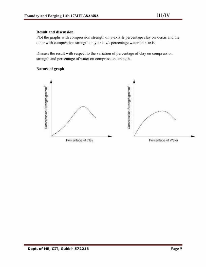
Result and discussion Plot the graphs with compression strength on y-axis & percentage clay on x-axis and the other with compression strength on y-axis v/s percentage water on x-axis. Discuss the result with respect to the variation of percentage of clay on compression strength and percentage of water on compression strength.
Nature of graph

Foundry and Forging Lab 17MEL38A/48A III/IV Dept. of ME, CIT, Gubbi- 572216 Page 10
TABULAR COLUMN
1. VARYING THE % OF CLAY 2. VARYING THE % OF WATER
SL. NO
Percentage of sand
Percentage of clay
Percentage of water
Shear strength gm/cm2 1 90%(180gms) 6%(12gms) 4%(8gms) 2 88%(176gms) 6%(12gms) 6%(12gms) 3 86%(172gms) 6%(12gms) 8%(16gms)
Graphs: a) Shear strength (Y-axis) V/s Percentage of clay (X-axis). b) Shear strength (Y-axis) V/s Percentage of water (X-axis).
SL. NO
Percentage of sand
Percentage of clay
Percentage of water
Shear strength gm/cm2 1 91%(182gms) 4%(8gms) 5%(10gms) 2 89%(178gms) 6%(12gms) 5%(10gms) 3 87%(174gms) 8%(16gms) 5%(10gms)

Foundry and Forging Lab 17MEL38A/48A III/IV Dept. of ME, CIT, Gubbi- 572216 Page 11
Experiment No. 2 Date: __ /__ / _____
SHEAR STRENGTH TEST FOR MOULDING SAND AIM: To determine the green shear strength of the given specimen for different percentages of clay and moisture. Materials used: Base sand, clay, water. Apparatus used: Sand ramming machine (rammer), universal sand testing machine with attachments, weighing pan. Theory: 1. Shear strength is the ability of sand particles to resist the shear stress and to stick together. 2. Insufficient Shear strength may lead to the collapsing of sand in the mould or its partial destruction during handling. The mould and core may also be damaged during flow of molten metal in the mould cavity. 3. The moulding sand must possess sufficient strength to permit the mould to be formed to the desired shape and to retain the shape even after the hot metal is poured into the mould cavity. 4. In shearing, the rupture occurs parallel to the axis of the specimen. Procedure: 1. Conduct the experiment in two parts: a) Vary the clay content keeping the water content constant b) Vary the water content keeping the clay content constant 2. Take weighed amount of foundry sand (mixture of sand, clay & water as specified). 3. Transfer the sand mixture into the tube and ram it with the help of a sand rammer thrice. 4. Fix the shackles to the universal sand testing machine. 5. Remove the specimen from the tube with the help of a stripper and load it into the universal sand testing machine. 6. Preliminary adjustments are made before applying the hydraulic pressure of the testing machine 7. Apply the hydraulic pressure by rotating the handle of the universal sand testing machine continuously until the specimen ruptures. 8. Read the shear strength directly from the scale and tabulate the readings.

Foundry and Forging Lab 17MEL38A/48A III/IV Dept. of ME, CIT, Gubbi- 572216 Page 12
Results and Discussions: The Graphs above reveal: a) With the increase in the percentage of water the shear strength of the specimen ……………………………. b) With the increase in the percentage of clay the shear strength of the specimen …………………………….

Foundry and Forging Lab 17MEL38A/48A III/IV Dept. of ME, CIT, Gubbi- 572216 Page 13
Experiment No. 3 Date: __ /__ / _____
TENSILE STRENGTH TEST OF CORE SAND AIM: To determine the tensile strength of sand using two types of binders Viz. core oil binder and sodium silicate binder. Materials used: Base sand, core oil, sodium silicate. Apparatus used: universal sand testing machine, Split core box, Sand rammer, oven, tension shackles. Theory: 1. A core is compacted sand mass of a known shape. 2. When a hollow casting (to have a hole – through or bind) is required, a core is used in the mould or when a complex contour is required a mould is created out of cores. This core has to be properly seated in the mould on formed impressions in the sand. To form these impressions extra projections called core points are added on the pattern surface at proper places. 3. Core boxes are used for making cores. They are either made single or in two parts. Their classification is generally according to the shape of the core or the method of making the core. 4. Split core box is very widely used and is made in two parts, which can be joined together by means of dowels to form the complete cavity for making the core. 5. The purpose of adding binder to the moulding sand is to impart strength and cohesiveness to the sand to enable it to retain its shape after the core has been rammed. 6. binders used can be a) organic: ex. Dextrin, core oil b) Inorganic: ex. Sodium silicate, Bentonite 7. Classification of binders: a. Baking type: Binding action is realized in the sand after baking the sand mixture in an oven. b. Gassing type: Binding action is obtained in the sand after passing a known gas through the sand mixture. Ex. Co2 gas passed through a mixture of sand and sodium silicate. 8. Core oil is used as binder that hardens with the addition of heat. The sand and binder is mixed and backed at a temperature of 250O – 300O C and binding action takes place within few hours. 9. Sodium silicate is a self setting binder and no external heat is required for the binding action which takes place at room temperature when Co2 gas is passed.
10. During casting the core is placed inside the mould and the molten metal is poured in to the cavity. As the molten metal begins to cool, it begins to contract on the inner radius as

Foundry and Forging Lab 17MEL38A/48A III/IV Dept. of ME, CIT, Gubbi- 572216 Page 14
TABULAR COLUMN
SL. NO
Percentage of sand
Percentage of sodium Silicate or core oil Tensile strength N/m2 1 2 3 4 5 6
Result and discussion: Discuss the effect of variation of binder content on tensile strength.

Foundry and Forging Lab 17MEL38A/48A III/IV Dept. of ME, CIT, Gubbi- 572216 Page 15

Foundry and Forging Lab 17MEL38A/48A III/IV Dept. of ME, CIT, Gubbi- 572216 Page 16
TENSILE CORE BOX
Tensile strength attachment (Model-VAS)
Foundry and Forging Lab 17MEL38A/48A III/IV Dept. of ME, CIT, Gubbi- 572216 Page 17
well as the outer radius. Due to the contraction of the inner radius the core sand will be pulled outwards causing a tensile load around the core. Hence knowledge of tensile strength of core sand is important. Procedure: 1. Conduct the experiment in two parts. a. Using core oil as binder and b. Using sodium silicate as binder. 2. Take proper proportions of base sand and binder then mix them together thoroughly. 3. Assembly the core box and fill the mixture into it. 4. Place the core box under sand rammer and ram the sand thrice. 5. Using a wooden piece tap the core box gently from sides. Remove the core box leaving the rammed core on a flat metal plate 6. Bake the specimen (which is on a plate) for about 30 minutes at a temperature of 150O – 200O C in an oven. (When the binder is core oil) 7. If the binder is sodium silicate, pass Co2 gas for 5 secs. The core hardens instantly and the core can be directly used. 8. Fix the tension shackles on to the sand testing machine, and place the hardened specimen in the shackles. 9. Apply the load gradually by turning the hand wheel of the testing machine. Note down the readings when the specimen breaks. 10. Repeat the procedure for the different percentage of binder and tabulate the readings.

Foundry and Forging Lab 17MEL38A/48A III/IV Dept. of ME, CIT, Gubbi- 572216 Page 18
TABULAR COLUMN
1. Varying the percentage of Clay and keeping percentage of Water constant (5%). 2. Varying the percentage of water and keeping percentage of Clay constant (6%).
Draw graph: Permeability number v/s % of Clay Permeability number v/s % of water Discuss the effect of water and clay on Permeability
SL. NO
Percentage of Clay
Pressure gm/cm2 Time in min.
PN
Indicated Calculated 1 4%(8gms) 2 6%(12gms) 3 8%(16gms) SL. NO
Percentage of water
Pressure gm/cm2 Time in min.
PN
Indicated Calculated 1 4%(8gms) 2 6%(12gms) 3 8%(16gms)

Foundry and Forging Lab 17MEL38A/48A III/IV Dept. of ME, CIT, Gubbi- 572216 Page 19
Experiment No. 4 Date: __ /__ / _____
PERMEABILITY TEST AIM: To find the effect of water content, clay content on green permeability of foundry sand. Materials used: Base sand, clay and water. Apparatus used: Sand rammer, Permeability meter, Electronic weighing scale, stripper, stop watch, measuring jar, specimen tube, specimen tube cup. Theory: 1. Molten metals always contain certain amount of dissolved gases, which are evolved when the metal starts freezing. 2. When molten meal comes in contact with moist sand, generates steam or water vapour. 3. Gases and water vapour are released in the mould cavity by the molten metal and sand. If they do not find opportunity to escape completely through the mould, they will get entrapped and form gas holes or pores in the casting. The sand must therefore be sufficiently porous to allow the gases and water vapour to escape out. This property of sand is referred to as permeability. 4. Permeability is one of the most important properties affecting the characteristic of moulds which depends upon the grain size, grain shape, grain distribution, binder content, moisture level and degree of compactness. 5. Permeability is a physical property of the physical sand mixture, which allows gases to pass through it easily. 6. The AFS (American Foundry Men Society) definition of permeability is “the number obtained by passing 2000cc of air through a standard specimen under a pressure of 10 gm/cm2 for a given time in minutes”. 7. The permeability number PN can be found out by the equation PN = Where V = Volume of air passing through the specimen, 2000cc H = Height of the specimen = 50.8 mm (standard value) P = Pressure as read from the manometer in gm/cm2 A = Area of the specimen = πd2/4 Where d = 50.8 mm (standard value) T= time in minutes for 2000 cc of air passed through the sand specimen.

Foundry and Forging Lab 17MEL38A/48A III/IV Dept. of ME, CIT, Gubbi- 572216 Page 20
PERMEABILITY METER
Nature of graph

Foundry and Forging Lab 17MEL38A/48A III/IV Dept. of ME, CIT, Gubbi- 572216 Page 21
Experimental setup details: Permeability meter has a cylindrical water tank in which an air tank is floating. By properly opening the valve, air from the air tank can be made to flow through the sand specimen and a back pressure is setup. The pressure of this air is obtained with the water manometer. The meter also contains the chart, which directly gives the PN depending on pressure. Procedure: 1. Conduct the experiment in two parts. In the first case vary water percent keeping clay percent constant. In the second case vary clay percent and keep water percent constant. 2. Take weighed proportions of sand dry mix them together for 3 minutes. Then add required proportions of water and wet mix for another 2 minutes, to get a homogeneous and mixture. Take the total weight of the mixture between 150-200 grams. The correct weight has to be determined by trail and error method. 3. Fill the sand mixture into the specimen tube and ram thrice using sand rammer. Use the tolerance limit provided at the top end of the rammer for checking the specimen size. If the top end of the rammer is within the tolerance limit, the correct specimen is obtained. If it lies below the limit, increase the weight of sand mixture and prepare a new specimen. The specimen conforming to within limits represent the standard specimen required. 4. Now the prepared standard specimen is having a dia.50.8mm and height 50.8mm. 5. Place the standard specimen along with the tube in the inverted position on the rubber seal or on the mercury cup (specimen in the top position in the manometer reading). 6. Operate the valve and start the stop watch simultaneously. When the zero mark on the inverted jar just touches the top of water tank, note down the manometer reading. 7. Note down the time required to pass 2000cc of air through the specimen. Calculate the permeability number by using the formula given. Direct scale reading: The permeability can also be determined by making use of the graduated marker provided near the manometer. Procedure to be followed:
• Coincide the graduations on the transparent scale with the meniscus of the manometer liquid. • Note the reading of the scale. • This reading represents the permeability number of the sand.

Foundry and Forging Lab 17MEL38A/48A III/IV Dept. of ME, CIT, Gubbi- 572216 Page 22
Tabular column for Core Hardness Test SL. NO % of Sand % of sodium silicate Core Hardness Number 1 2 3
Tabular column for Mould Hardness Test
SL. NO % of Sand % of Water Mould hardness Number 1 2 3

Foundry and Forging Lab 17MEL38A/48A III/IV Dept. of ME, CIT, Gubbi- 572216 Page 23
Experiment No. 5 Date: __ /__ / _____
CORE HARDNESS AND MOULD HARDNESS TEST Mould and core hardness can be found out by the hardness – tester which is base on the same principle as Brinell hardness tester. A steel ball of 50 mm diameter weighing 237 gm is pressed on the mould surface. The depth of penetration of steel ball will give the hardness of mould surface on the direct reading dial. This hardness test is useful in finding out the mould uniformity The following are the moulding hardness numbers for Moulding sand (1 number = 1/100 mm) Soft rammed moulds = 100 Medium rammed moulds = 125 Hard rammed mould = 175

Foundry and Forging Lab 17MEL38A/48A III/IV Dept. of ME, CIT, Gubbi- 572216 Page 24
Tabular Column: Total weight of sand taken = 100g.
SL. NO
(a) Sieve NO in
Microns
(b) Weight in grams (c)
% Retained
(d) Multiplying
factor
(e) Product ∑e = c x d
Empty Sieve W1
Sieve with Sand W2 1 1700 5 2 850 10 3 600 20 4 425 30 5 300 40 6 212 50 7 150 70 8 106 100 9 75 140 10 53 200 11 Sieve pan 300 P= ∑c Q = ∑e (Calculate the average GFN using the formula as shown below.) % Retained C = Weight of sand in each sieve x 100 Total weight of sand Calculation: AFS grain number = Q (sum) / P (total)
Results: The average grain fineness number is =

Foundry and Forging Lab 17MEL38A/48A III/IV Dept. of ME, CIT, Gubbi- 572216 Page 25
Experiment No. 6 Date: __ /__ / _____
SIEVE ANALYSIS TO FIND GRAIN FINENESS NUMBER OF BASE SAND AIM: To find the distribution of sand grains using a set of sieves and to find the average grain fineness number. Materials used: Base sand- Silica sand. Apparatus used: Electronic weighing scale, stop watch, sieve shaker. Theory: 1. The base sand is a mixture of grains having a variety of shapes such as a) Round b) sub-angular c) angular d) compounded grains. Base sand is relatively free from any binder or additives. 2. Depending on the average size of the grains, the sand can be grouped into: a) Fine b) Medium and c) Coarse grains. 3. The shape and size of grains has a large influence on the permeability of sand mix as well as on the bonding action. 4. The shape and size of grains determine the possibility of its application in various types of foundry practice. Ex: Fine grain sand results in good surface, on the casting but gases cannot escape out of the mould made from it. Coarse grain sand allows gases to escape out easily but the casting surface will be very rough. Hence grain size should select appropriately. 5. The given size of sand grains is designated by a number called grain fineness number that indicates the average size of grains in the mixture. 6. The size is determined by passing the sand through sieves having specified apparatus which are measured in microns. 7. The sieve number designates the pore size through which the sand grains, may pass through it or retained in it. 8. Average grains fineness number can be found out by the equation GFN = Q/P Where Q = sum of product of percentage sand retained in sieves and Corresponding multiplier. P = sum of percentage of sand retained in sieves.

Foundry and Forging Lab 17MEL38A/48A III/IV Dept. of ME, CIT, Gubbi- 572216 Page 26
SIEVE SHAKER
Graph: Percentage of sand retained v/s sieve number Nature of graph

Foundry and Forging Lab 17MEL38A/48A III/IV Dept. of ME, CIT, Gubbi- 572216 Page 27
Procedure: 1. Take 50 gm or100 gm of dry sand and place in the top sieve of a series and close the lid. 2. Place the whole assembly of sieves on the vibratory sieve shaker and clamp it. 3. Switch on the motor and allow the sieve assembly to vibrate for 5 minutes. Then switch off the motor. 4. Collect the sand particles retained in each of the sieve separately and weigh in Electronic weighing scale and enter into the tabular column. Calculate the percentage weight retained by each of the sieves. Multiply this value with the multiplier for each sieve.

Foundry and Forging Lab 17MEL38A/48A III/IV Dept. of ME, CIT, Gubbi- 572216 Page 28
Calculations Weight of sand W1= 100 gms Weight of dried sand W2 = ----------- gms % of clay= ( W1- W2) X 100 100 Results and discussion: The percentage of clay is =___________% Discuss whether the % of clay is present is high or low and whether this % is enough to act as binder in the sand.
CLAY WASHER
Foundry and Forging Lab 17MEL38A/48A III/IV Dept. of ME, CIT, Gubbi- 572216 Page 29
Experiment No. 7 Date: __ /__ / _____
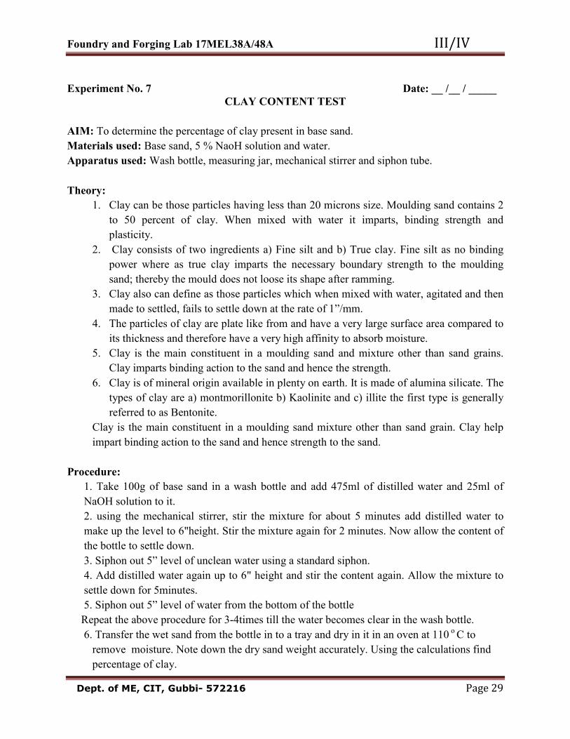
CLAY CONTENT TEST AIM: To determine the percentage of clay present in base sand. Materials used: Base sand, 5 % NaoH solution and water. Apparatus used: Wash bottle, measuring jar, mechanical stirrer and siphon tube. Theory: 1. Clay can be those particles having less than 20 microns size. Moulding sand contains 2 to 50 percent of clay. When mixed with water it imparts, binding strength and plasticity. 2. Clay consists of two ingredients a) Fine silt and b) True clay. Fine silt as no binding power where as true clay imparts the necessary boundary strength to the moulding sand; thereby the mould does not loose its shape after ramming. 3. Clay also can define as those particles which when mixed with water, agitated and then made to settled, fails to settle down at the rate of 1”/mm. 4. The particles of clay are plate like from and have a very large surface area compared to its thickness and therefore have a very high affinity to absorb moisture. 5. Clay is the main constituent in a moulding sand and mixture other than sand grains. Clay imparts binding action to the sand and hence the strength. 6. Clay is of mineral origin available in plenty on earth. It is made of alumina silicate. The types of clay are a) montmorillonite b) Kaolinite and c) illite the first type is generally referred to as Bentonite. Clay is the main constituent in a moulding sand mixture other than sand grain. Clay help impart binding action to the sand and hence strength to the sand. Procedure: 1. Take 100g of base sand in a wash bottle and add 475ml of distilled water and 25ml of NaOH solution to it. 2. using the mechanical stirrer, stir the mixture for about 5 minutes add distilled water to make up the level to 6"height. Stir the mixture again for 2 minutes. Now allow the content of the bottle to settle down. 3. Siphon out 5” level of unclean water using a standard siphon. 4. Add distilled water again up to 6" height and stir the content again. Allow the mixture to settle down for 5minutes. 5. Siphon out 5” level of water from the bottom of the bottle Repeat the above procedure for 3-4times till the water becomes clear in the wash bottle. 6. Transfer the wet sand from the bottle in to a tray and dry in it in an oven at 110 o C to remove moisture. Note down the dry sand weight accurately. Using the calculations find percentage of clay.

Foundry and Forging Lab 17MEL38A/48A III/IV Dept. of ME, CIT, Gubbi- 572216 Page 30

Foundry and Forging Lab 17MEL38A/48A III/IV Dept. of ME, CIT, Gubbi- 572216 Page 31
PART – B
FOUNDRY
Foundry and Forging Lab 17MEL38A/48A III/IV Dept. of ME, CIT, Gubbi- 572216 Page 32

Foundry and Forging Lab 17MEL38A/48A III/IV Dept. of ME, CIT, Gubbi- 572216 Page 33
FOUNDRY Introduction: Foundry is a process of shaping the metal components in their molten stage. It is the also called as metal casting the shape and size of the metal casting is obtained depends on the shape and size of the cavity produced in sand mould by using wooden/ metal pattern. Practical application 1. Casting is the cheapest and most direct way of producing the shape of the component 2. Casting is best suited to work where components required is in low quantity. 3. Complicated shapes having internal openings and complex section variation can be produced quickly and cheaply by casting since liquid metal can flow into any form/ shape. Example: 1. Outer casing of all automobile engines. 2. Electric motor housing 3. Bench vice, Irrigation pumps etc. 4. Heavy equipment such as machine beds of lathe, milling machine, shaping, drilling planing machine etc. can be cast/easily 5. Casting is best suited for composite components Example.1. steel screw threads in zinc die casting All conductors into slot in iron armature for electric motor. Steps in foundry process The Foundry process involves three steps. (a) Making the required pattern (b) Moulding process to produce the cavity in sand using pattern. (c) Pouring the molten metal into the cavity to get casting.

Foundry and Forging Lab 17MEL38A/48A III/IV Dept. of ME, CIT, Gubbi- 572216 Page 34
Classification of foundries
• Steel foundry • C.I foundry • Light alloy foundry • Brass foundry • Shell moulding foundry • Die casting foundry (using permanent metal or dies for high volume of low and pressure die) Pattern: A pattern is normally a wooden/ metal model or thermosetting plastic which is facsimile of the cast product to be made, there are many types of pattern and are either one piece, two piece or three piece, split pattern, loose piece pattern, Gated and match plate pattern etc. Pattern size: Actual casting size +shrinkage allowance +shake allowance +finish allowance 1. Shrinkage allowance: The liquid metal shrinks during solidification and it contraction to its room temperature, so that the pattern must be made larger then the casting to provide for total contraction. 2. Finishing allowance: The casting is to be machined at some points then the casting should be provided with excess metal for machining. Types of foundry sand 1. Natural sand: Sand containing the silica grains and clay bond as found. It varies in grain size and clay content. Collected from natural recourses. 2. Synthetic sand: It is an artificial sand obtained by mixing relatively clay free sand, binder (water and bentonoite). It is better moulding sand as its properties can be easily controlled.

Foundry and Forging Lab 17MEL38A/48A III/IV Dept. of ME, CIT, Gubbi- 572216 Page 35
3. Facing sand: It is the fine grade sand used against the face of the pattern and finally governs the surface finish of the casting. 4. Parting sand: It is fine dry sand + brick dust used to preserve the joint face between the cope and the drag. Natural Green sand= sand + clay + moisture (10 to 15%) (7 to 9%) Synthetic Green sand= sand + clay + moisture (5 to 7%) (4 to 8%) 5. Green sand: mouldings is the most common moulding process 5. Dry sand mould: Dry sand mould refer to a mould which is artificially dried before the molten metal is poured into it. Dry sand moulds are costly, stronger, used for complicated castings, i.e. avoid casting defects, casting gets smoother surface. Moulding methods:
• Bench moulding: In this method the moulding is carried out on convenient bench and moulds are relatively small. • Floor mouldings: In this method the mouldings is carried out in medium and large moulds are carried out on the floor. • Plate mouldings: For large quantity production and for very heavy casting two plates may be used with pattern. • Pit moulding: In this method the moulding is carried out in the pits and generally very large moulds are made. • Machine mouldings: A machine is used to prepare moulds of small and medium. This method is faster and gives uniform mouldings.

Foundry and Forging Lab 17MEL38A/48A III/IV Dept. of ME, CIT, Gubbi- 572216 Page 36
CORE AND CORE MAKING
CORES: Cores are sand blocks they are used to make hollow portion in a casting. It is placed in a mould so that when molten metal is poured into the mould. This apart of mould will remain vacant i.e. the molten metal will not fill this part of the mould. So when the mould is broken and the castings removed a hollow portion will result in the casting. Core sand= Moulding sand+ binders (ABC core oil) or sodium silicate
Core making: Cores are made separately in a core box made of wood or metal.
Core binders 1. Water soluble binders (2 t0 4% by weight) 2. Oil binders (1-3% by weight) 3. Pitch and resin binders (1-35 by weight) The sand is treated with binder to achieve cohesion
Core Baking The core is baked (hardened) by heating at 150C depends on core size in oven. This hardening of the core helps to handle and to place the core in the mould. The core is supported in the mould by projection known as core prints.

Foundry and Forging Lab 17MEL38A/48A III/IV Dept. of ME, CIT, Gubbi- 572216 Page 37
NOMENCLATURE OF A MOULD

Foundry and Forging Lab 17MEL38A/48A III/IV Dept. of ME, CIT, Gubbi- 572216 Page 38
MOULDING TOOLS & EQUIPMENTS

Foundry and Forging Lab 17MEL38A/48A III/IV Dept. of ME, CIT, Gubbi- 572216 Page 39

Foundry and Forging Lab 17MEL38A/48A III/IV Dept. of ME, CIT, Gubbi- 572216 Page 40

Foundry and Forging Lab 17MEL38A/48A III/IV Dept. of ME, CIT, Gubbi- 572216 Page 41

Foundry and Forging Lab 17MEL38A/48A III/IV Dept. of ME, CIT, Gubbi- 572216 Page 42

Foundry and Forging Lab 17MEL38A/48A III/IV Dept. of ME, CIT, Gubbi- 572216 Page 43

Foundry and Forging Lab 17MEL38A/48A III/IV Dept. of ME, CIT, Gubbi- 572216 Page 44

Foundry and Forging Lab 17MEL38A/48A III/IV Dept. of ME, CIT, Gubbi- 572216 Page 45
Trowels: These are used for working up into a square corner. Taper trowel: It is more useful for working along the curved edges of a pattern. Trowels are measured by the length and width of the blade. Slicks: Use for repairing and slicking of small surfaces. They are named according to the shape of the blade and measured at the widest part of the blade. Lifters and Cleaners: They are used to clean & finish the bottom and sides of deep narrow openings. Gate Knife: is for cutting the channel from the mould to the bottom of the runner or riser. Spoon tool: is convenient for cutting the pouring basin. Corner Slicks: are, as the shape implies, for finishing off fillets and corners of moulds. Draw Spike: is a spike for knocking into the wooden pattern in order to withdraw it. Draw Screw: is for the same purpose as the draw spike; the end is threaded to screw into the rapping plate. Swap: is a soft – pointed brush for moistening the edges of the mould before lifting the pattern. The angle at which it is held will decide the area to be covered. Care must be taken not to get the sand too damp. Bellows: are used for blowing out loose sand from the completed mould; they must be used gently; too vigorous use will damage the mould.

Foundry and Forging Lab 17MEL38A/48A III/IV Dept. of ME, CIT, Gubbi- 572216 Page 46
Working steps in making the sand casting
• Place the pattern on the turn over board. • Place the drag around the pattern with upside and sprinkle the parting sand at the bottom. • Fill the Moulding sand over the pattern pack, Ram, Jolt & squeeze. • Level the bottom drag surface by leveller & turn over the drag. • Sprinkle the parting sand, place the cope on the drag to suit the drag slot. • Select the in and out gate in the drag, Place the sprue pins. • Fill the moulding sand around the sprue pins pack, Ram, Jolt and Squeeze & level the surface. • Make vent holes on both the boxes with the help of vent wire. • Remove the sprue pin & Separate cope from drag. • Remove the pattern carefully with the help of draw pin, Cut gate ways to flow the molten metal. • From the funnel shape on runner & riser, Hole to pour the molten metal on the top of the cope box. • Join the two boxes with clamps, Now the mould is ready to pour the molten metal.

Foundry and Forging Lab 17MEL38A/48A III/IV Dept. of ME, CIT, Gubbi- 572216 Page 47

Foundry and Forging Lab 17MEL38A/48A III/IV Dept. of ME, CIT, Gubbi- 572216 Page 48
Experiment No. 1 Date: __ /__ / _____ Exercise No. 1
Solid Pattern
W1 W2 All dimensions are in mm
Foundry and Forging Lab 17MEL38A/48A III/IV Dept. of ME, CIT, Gubbi- 572216 Page 49
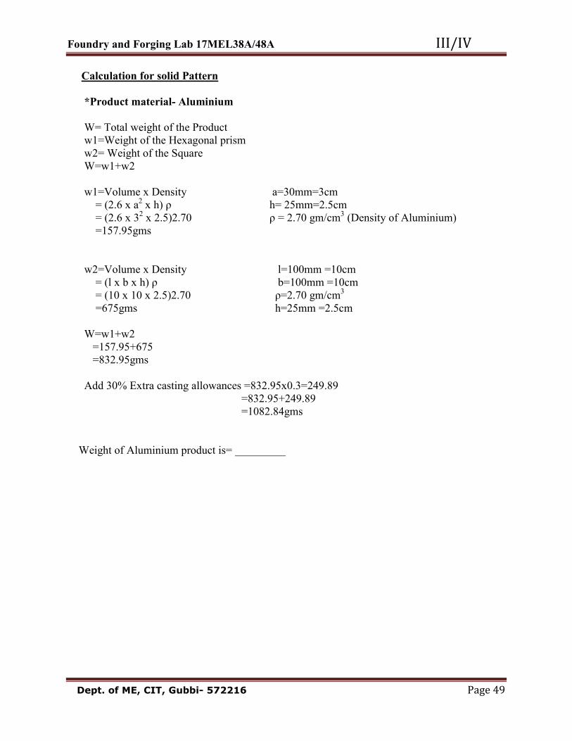
Calculation for solid Pattern *Product material- Aluminium W= Total weight of the Product w1=Weight of the Hexagonal prism w2= Weight of the Square W=w1+w2 w1=Volume x Density a=30mm=3cm = (2.6 x a2 x h) ρ h= 25mm=2.5cm = (2.6 x 32 x 2.5)2.70 ρ = 2.70 gm/cm3 (Density of Aluminium) =157.95gms w2=Volume x Density l=100mm =10cm = (l x b x h) ρ b=100mm =10cm = (10 x 10 x 2.5)2.70 ρ=2.70 gm/cm3 =675gms h=25mm =2.5cm W=w1+w2 =157.95+675 =832.95gms Add 30% Extra casting allowances =832.95x0.3=249.89 =832.95+249.89 =1082.84gms Weight of Aluminium product is= _________

Foundry and Forging Lab 17MEL38A/48A III/IV Dept. of ME, CIT, Gubbi- 572216 Page 50
Experiment No. 2 Date: __ /__ / _____ Exercise No. 2
Hand Cutting
W2 W1 All dimensions are in mm

Foundry and Forging Lab 17MEL38A/48A III/IV Dept. of ME, CIT, Gubbi- 572216 Page 51
Calculation for Hand Cutting
*Product material- Aluminium W= Total weight of the Product w1=Weight of the Cylinder w2= Weight of the Square W=w1+w2 w1=Volume x Density d=100mm=10cm w1= (A x L) ρ l= 30mm=3cm = (∏d2/4 x L) ρ ρ= 2.70 gm/cm3 = (∏102/4 x 3) 2.7 =636.17gms w2=Volume x Density l=20mm=2cm = (l x b x h) ρ b=50mm=5cm = (2 x 5 x 5) 2.70 ρ=2.70 gm/cm3 =135gms h=50mm=5cm W=w1+w2 =771.17gms Add 30% Extra casting allowances =771.17x0.3= 231.35gms =771.17+231.35 =1002.52gms Weight of final product is 1002.52gms.

Foundry and Forging Lab 17MEL38A/48A III/IV Dept. of ME, CIT, Gubbi- 572216 Page 52
Experiment No. 3 Date: __ /__ / _____ Exercise No. 3
Self Cored Pattern
Ø (Cylinder ‘c’) Ø (Cylinder ‘b’) Ø (Cylinder ‘a’) All dimensions are in mm

Foundry and Forging Lab 17MEL38A/48A III/IV Dept. of ME, CIT, Gubbi- 572216 Page 53
Calculation for Self Cored Pattern *Product material- Aluminium
W= Total Weight of the Product w1=Weight of the Cylinder (a) w2= Weight of the Cylinder (b) w3= Weight of the Cylinder (c) W=w1+w2-w3 w1=Volume x Density d=90mm=9cm w1= (A x L) ρ L= 25mm=2.5cm = (∏d2/4 x L) ρ ρ=2.70 gm/cm3 = (∏ (9)2/4 x 2.5) 2.7 =429.42gms W2=Volume x Density d=65mm=6.5cm W2= (A x L) ρ L= 25mm=2.5cm = (∏d2/4 x L) ρ ρ=2.70 gm/cm3 = (∏ (6.5)2/4 x 2.5)2.7 =223.98gms w1=Volume x Density d=40mm=4cm w1= (A x L) ρ L= 50mm=5cm = (∏d2/4 x L) ρ ρ=2.70 gm/cm3 = (∏ (4)2/4 x 5) 2.7 =169.65gms W= (w1+w2)-w3 = (429.42+223.98)-169.65 =653.4-169.65 = 483.75gms Add 30% Extra casting allowance =483.75x0.3= 145.13 =483.75+145.13 =628.88gms Weight of final product is 628.88 gms

Foundry and Forging Lab 17MEL38A/48A III/IV Dept. of ME, CIT, Gubbi- 572216 Page 54
Experiment No. 4 Date: __ /__ / _____ Exercise No. 4
Stepped Cone Pulley With Core Print
Ø ø ø ø All dimensions are in mm

Foundry and Forging Lab 17MEL38A/48A III/IV Dept. of ME, CIT, Gubbi- 572216 Page 55
Calculation:

Foundry and Forging Lab 17MEL38A/48A III/IV Dept. of ME, CIT, Gubbi- 572216 Page 56
Experiment No. 5 Date: __ /__ / _____ Exercise No. 5
Split Pattern with Two Halves ø ø ø
All dimensions are in mm

Foundry and Forging Lab 17MEL38A/48A III/IV Dept. of ME, CIT, Gubbi- 572216 Page 57
Calculation:

Foundry and Forging Lab 17MEL38A/48A III/IV Dept. of ME, CIT, Gubbi- 572216 Page 58
Experiment No. 6 Date: __ /__ / _____ Exercise No. 6
Loose Piece Pattern [additional]
All dimensions are in mm

Foundry and Forging Lab 17MEL38A/48A III/IV Dept. of ME, CIT, Gubbi- 572216 Page 59
Calculation:

Foundry and Forging Lab 17MEL38A/48A III/IV Dept. of ME, CIT, Gubbi- 572216 Page 60
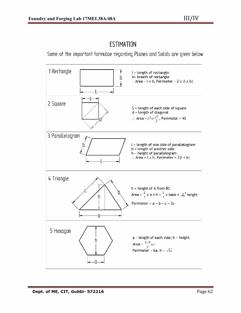
Estimation of Material Costs In this chapter the material cost means the direct material cost. The frequently used materials are: Aluminum, Copper, Gunmetal, Brass, Iron, Tin, Magnesium, Mild steel, Alloy steel & Lead etc. The generalized procedure to calculate the Material Cost: 1. Observe the component drawings, break up the drawing into simple parts as per convenience. 2. Using formulae calculate area & Volume of each part. Scrap should be taken into account while calculating the volume. 3. Add the Volume of all the parts. 4. Multiply the component volume & density of material. It will be weight of the component. Density X Volume = Weight. 5. Multiply the weight of the component with the cost of material per unit weight. The following table gives the densities of various materials:
No. Material Density Gm/cc
No. Material Density Gm/cc 1 Aluminum Cast 2.70 2. Al-wrought 2.681 3. Cast Iron 7.209 4. Wrought-Iron 7.707 5. Steel 7.868 6. Mild Steel 7.2 7. Brass-Cast 8.109 8. Brass-Wire 8.382 9. Bronze 8.7 10. Gun Metal 8.735 11. Zinc-Cast 6.872 12. Zinc Sheet 7.209 13. Copper 8.622 14. Gold 19.316 15. Lead 11.368 16. Tin 7.418
Solved Examples: Stepped Pulley: QNo 1. A Cast-Iron Step cone pulley is shown in the following Figure. The Density of the C.I. is 7.209 gm/cc, Material Cost is Rs.20/ kg. Calculate the weight and material cost. Solutions:

Foundry and Forging Lab 17MEL38A/48A III/IV Dept. of ME, CIT, Gubbi- 572216 Page 61
Let L, M, N, P are the different parts of the fig shown. Total Length of the Fig.=80+80+80 = 240 mm Now calculate the volume of Each Part: a) Volume of hole i.e., Part ‘L’ 3222 584.6786785842406044 cmmmxxxlxdVL ====λλ b) Volume of part ‘M’:- 3322 99.392639269908025044 cmmmxxxlxdVM ====
λλ c) Volume of part ‘N’:- 3322 72.2035203575280)180(44 cmmmxxxlxdVN ====λλ d) Volume of part ‘P’:- 3322 778.90468.9047788012044 cmmmxxxlxdVP ====λλ The volume of the fig= (b + c + d) – a = (3926.99 + 2035.72 + 904.778) – 678.584 = 6188.904 3cm Total weight of the fig.= Volume of the fig. X Density of the CI Material = 6188.904 X 7.209 = 44615.809 gm. = 44.615 kg Assume the Rate of CI = Rs. 75/- Cost of the Material Required = Weight X Cost = 44. 615 X Rs. 75 = Rs. 3346.125
Foundry and Forging Lab 17MEL38A/48A III/IV Dept. of ME, CIT, Gubbi- 572216 Page 62

Foundry and Forging Lab 17MEL38A/48A III/IV Dept. of ME, CIT, Gubbi- 572216 Page 63

Foundry and Forging Lab 17MEL38A/48A III/IV Dept. of ME, CIT, Gubbi- 572216 Page 64

Foundry and Forging Lab 17MEL38A/48A III/IV Dept. of ME, CIT, Gubbi- 572216 Page 65
PART – C
FORGING

Foundry and Forging Lab 17MEL38A/48A III/IV Dept. of ME, CIT, Gubbi- 572216 Page 66

Foundry and Forging Lab 17MEL38A/48A III/IV Dept. of ME, CIT, Gubbi- 572216 Page 67
FORGING Introduction: Forging is a process of shaping the metal components in cold or hot condition by the application of impact or pressure but the primary difference between various forging methods is the rate which the energy is applied to the work piece. Practical Application: Forging is generally used for those components which require high strength and resistance to shock or vibration sudden impact of load and uniform properties Example: Automobiles (1) chassis of all vehicles (2) Front and Rear axel (3) Wheel drums (4) Spring blades (5) Rocker arm (6) Gear shifter (7) Connecting rod etc. Railways (1) Railway wheels (2) Railway tracks General (1) D. E. Spanners (2) Ring Spanner (3) Wrenches (4) Cutting Pliers (5) Hammers etc. FORGING METHODS (1) Hand forging (2) Drop forging (3) Press forging (4) Roll forging

Foundry and Forging Lab 17MEL38A/48A III/IV Dept. of ME, CIT, Gubbi- 572216 Page 68
Hand forging: Hand forging is made by heating the metal until it is plastic state in an open hearth furnace and there by hammering is done on anvil by smith/sledge hammer with use of open face dies to get the desired shape and size by judgment of an individual. Drop forging: In this process of forming the desired shape by placing a heated bar or billet on the lower half of the forging die and hammering the top half of the die into the metal by means of a power hammer by repeated blows the impact of which compel the plastic metal to conform the shape of the die. This method is used to produce large number of small and medium sized forging of similar parts. Press forging: In this process the heated billet is squeezed between die. The pressure is applied by the forging press which completes the operation in a single stroke. Large forging are generally shaped by thin method. Roll forging: Rolling involves the passing of a heated bar between revolving rolls that contains an impression of the required shape. It is used to reduce short thick section to long slender pieces.
FORGING operations; (1) Drawing down (2) Up setting (3) Punching (4) Bending (5) Welding (6) Cutting Drawing down: The operation of spreading or thinning action and is accomplished by striking the work piece with flat dies. Due to impact of die on metal its thickness is reduced and length is increased

Foundry and Forging Lab 17MEL38A/48A III/IV Dept. of ME, CIT, Gubbi- 572216 Page 69
Fullers: are blunt hosed chisel and are used to reduce the thickness of hot metal. They may be held with hand fitted with a rod handle. Bottom fullers may be inserted in the square hole of the anvil. Flatters: this is used to flatten and smoothen metal flatters are used under a sledge hammer to flatten the metal particularly after its thickness has been reduced using fullers.

Foundry and Forging Lab 17MEL38A/48A III/IV Dept. of ME, CIT, Gubbi- 572216 Page 70
Upsetting: This is just opposite to drawing and involves increasing of the cross sectional area usually by pressing or hammering in the direction parallel to the original in got axis. Only the part to be upset is heated to forging temper and the bar or work is then struck at the end, usually between the hammer and the axis as shown in figure. Punching: It is the process of producing hole generally cylindrical by using a hot punch over a cylindrical die. Drifting: It is the opening out of holes previously punched. Bending: It is one of the most important processes of forging and is very frequently used. Bends may be classified a sharp cornered bends or more gradual bends. The operation is performed by hammering the metal over the edge of the anvil or over a block of metal held in vice. When the metal is bending by hammering, the outer and inner surface does not remain same. The inside surface is shortened while the outer surface is stretched which causes bulging of the side at the inner surface and a radius on the outer surface of a sharp corner is required an

Foundry and Forging Lab 17MEL38A/48A III/IV Dept. of ME, CIT, Gubbi- 572216 Page 71
additional metal is required at the place where the bend occur in order to permit stretching of metal at outer surface. Welding: Metal like wrought iron and steel are welded by pressing or hammering together surface after they have been raised to the correct welding temperature at 1350ºC when the metal is white not. The operation of such a type of welding is performed in forge shop. And hence is also called forge welding. Cutting: In order to perform a rapid cutting operation by chiselling, the metal is heated in black smith fire to a temperature of 850-900ºC and then hammer blows are directed on the chisel head. If the thickness of metal to be cut is more then two notched or grooves are made 180º apart. Swaging: it is a process of finishing a round or hexagonal section of bar between a pair of swages of the appropriate size. These may be separate tools for top and bottom or these may be held to gather by a long spring handle as shown in figure.
Swages

Foundry and Forging Lab 17MEL38A/48A III/IV Dept. of ME, CIT, Gubbi- 572216 Page 72
TOOLS & EQUIPMENTS REQUIRED FOR FORGING.

Foundry and Forging Lab 17MEL38A/48A III/IV Dept. of ME, CIT, Gubbi- 572216 Page 73

Foundry and Forging Lab 17MEL38A/48A III/IV Dept. of ME, CIT, Gubbi- 572216 Page 74

Foundry and Forging Lab 17MEL38A/48A III/IV Dept. of ME, CIT, Gubbi- 572216 Page 75

Foundry and Forging Lab 17MEL38A/48A III/IV Dept. of ME, CIT, Gubbi- 572216 Page 76

Foundry and Forging Lab 17MEL38A/48A III/IV Dept. of ME, CIT, Gubbi- 572216 Page 77

Foundry and Forging Lab 17MEL38A/48A III/IV Dept. of ME, CIT, Gubbi- 572216 Page 78
Anvil: It is used as a mount for pairs of tools between which the work is forged by hammer blows. The main body of the anvil is made of mild steel with a hardened top face welded on. The beak is soft and with an increasing diameter of cross section. Beak is useful for producing bends of different radii. The ledge between the beak and the anvil face is soft and can be used as a base for cutting operation with hot chisels. Sledge hammer: It is a very heavy hammer with a long handle. It may weigh from 4 to 16 kg. These are used for heavy work. The length of the handle increases with the weight. Chisel: It is fitted with a long handle. The chisel is held on the work and struck with a hammer. Cold chisel: It is used for cutting cold metal. Hot chisel: It is used for cutting hot metal.

Foundry and Forging Lab 17MEL38A/48A III/IV Dept. of ME, CIT, Gubbi- 572216 Page 79
Hardie: This is a chisel fitted in to a hole in the anvil with its cutting edge at the top. There is usually one for hot and another for cold use. Swages: These are used in pairs to shape hot metal. They are supplied in pairs, top and bottom. Fullers: These are blunt nosed chisels and are used to reduce the thickness of hot metal. They may be held with hand or fitted with a rod handle. Bottom fullers may be inserted in the square hole of the anvil .For occasional use, fullers can be improvised from round mild steel bar. Flatter: This is used to flatten and smooth the metal. It is used under a sledge hammer to flatten and smoothen the metal, particularly after its thickness has been reduced using fullers. Tongs: These are used to hold hot metal pieces. Various shapes of blacksmith’s tongs are available.
Types of Tongs:
Single pick up tong: It is used to pick up either flat work or round work. Curved lip tong: This is also called as chisel or bolt tong. It is used to hold round work. Straight lip tong: It is also called as flat-jawed or flat mouth tong. It is used to hold flat work. Double hollow bit: It is used to pick up either flat work or round work.

Foundry and Forging Lab 17MEL38A/48A III/IV Dept. of ME, CIT, Gubbi- 572216 Page 80
Experiment No. 1 Date: __ /__ / _____ Exercise 1
HEX ALLEN KEY 10A/F
All dimensions are in mm Calculation of length of the raw material required to do the component W= Total weight of the finished product Hexagon = Volume x Density a= 6mm=0.6cm (Where a is side of hexagon) = (2.6 x a2 x L) ρ ρ = 7.2gm/cm3 (ρ is Density of mild steel) = (2.6 x 0.62 x 16) 7.2 L=160mm=16cm W = 107.8 gms To find length of the raw material required Total weight of the finished product (W) =weight of the raw material given (12mm MS Bar) Weight of bar = Volume x Density L =? W = (A x L) ρ d=12mm=1.2cm 107.8= (∏d2/4 x L) ρ ρ=7.2gm/cm3 107.8= (∏ (1.2)2/4 x L) 7.2 w=107.8 107.8=8.14L L= 13.25cm Add extra 10 % forging allowance =13.25x0.1=1.32 =13.25+1.32 Length of the raw material required =14.57cm

Foundry and Forging Lab 17MEL38A/48A III/IV Dept. of ME, CIT, Gubbi- 572216 Page 81
Working steps in making the Forging Job
1) Calculate the final length of the model to be forged of the given round rod of 12mm diameter. 2) Place the given round rod in the LPG Hearth furnace in suitable place. 3) Switch on the blower and set the temperature range up to 900-10000C in control panel. 4) The job is heated to red hot temperature. 5) Place the heated job in between open faced Bottom & Top Die, Which is set on Anvil. 6) Draw down the heated work piece to calculated length with the help of hammer, tong & flatter. 7) The process is carried approximately until the circular rod is transformed into desired shape and with desired dimensions. 8) The work piece is re-heated to carry out bending operation. 9) Bending is carried out on Leg vice as per dimensions. 10) With the help of flatter, open faced dies finish the work piece to the final dimension and surface finish; cool the specimen by dipping in water.

Foundry and Forging Lab 17MEL38A/48A III/IV Dept. of ME, CIT, Gubbi- 572216 Page 82
Experiment No. 2 Date: __ /__ / _____
Exercise 2
SQUARE SECTION NAIL
All dimensions are in mm Calculation of length of the raw material required to do the component W= Total weight of the finished product W=w1+w2 w1= square prism = volume x density L= 140mm=14cm = (L x b x h) ρ b= 12mm=1.2cm = (14 x 1.2 x 1.2) 7.2 h= 12mm=1.2cm = 145.15gms ρ = 7.2gm/cm3 w2=Square Pyramid = (1/3 x a2 x h) ρ a=12mm=1.2cm = (1/3 x 1.22 x 3) 7.2 h= 30mm=3cm = 10.36gms ρ = 7.2gm/cm3 W=w1+w2 =145.15+10.36 =155.51gms W = weight of the raw material MS round Weight= Volume x Density L=? 155.51 = (∏d2/4 x L) ρ d=16mm=1.6cm 155.51 = (∏(1.6)2/4 x L) 7.2 ρ = 7.2gm/cm3 L=10.74cm Add extra 10 % forging allowance =1.07 cm =10.74 + 1.07 Length of the raw material required = 11.81 cm

Foundry and Forging Lab 17MEL38A/48A III/IV Dept. of ME, CIT, Gubbi- 572216 Page 83

Foundry and Forging Lab 17MEL38A/48A III/IV Dept. of ME, CIT, Gubbi- 572216 Page 84
Experiment No.3 Date: __ /__ / _____ Exercise 3
T-BOLT (HEXAGONAL HEADED BOLT)
All dimensions are in mm Calculation of length of the raw material required to do the component W= weight of the finished product W=w1+w2 w1= Hexagon prism = (2.6 x a2 x L) ρ a=12mm=1.2cm (Where a is side of hexagon) = (2.6 x 1.22 x 0.8)7.2 L=8mm=0.8cm = 21.56gm ρ = 7.2gm/cm3 w2= Round = (∏d2/4 x L) ρ d=12mm=1.2cm = (∏ (1.2)2/4 x 5) 7.2 L=50mm=5cm = 40.71gm ρ = 7.2gm/cm3 W=w1+w2 = 21.56+40.71 = 62.27gm W = wt of the raw material MS Round d=12mm=1.2cm 62.27= (∏d2/4 x L) ρ L=? 62.27= (∏ (1.2)2/4 x L) 7.2 ρ=7.2gm/cm3 62.27=8.14L L= 7.65 cm Add extra 10 % forging allowance = 7.65x0.1=0.76 cm = 7.65 + 0.76 = 8.41 Length of the raw material required = 8.41cm

Foundry and Forging Lab 17MEL38A/48A III/IV Dept. of ME, CIT, Gubbi- 572216 Page 85
Viva Question with answers 1. What is core sand? Sand that prepared by mixing a special binder such as core oil with sand, that develop high strength. 2. What are the properties of good moulding sand? -Permeability -Cohesiveness or Strength - Adhesiveness -Plasticity -Refractoriness -Binding -Chemical resistivity -Flowbility. 3. What is molding sand? Its prepared by using a mixture of base sand, binder, additives and with or without water.The mixture of sand is referred to as moulding sand. 4. What is a binder? it is a material, which imparts the necessary binding action to the sand, a binder holds the sand grains together and induces strength and other properties to the moulds 5. What is green sand? –Containing 5-7% water and 6-10% clay it’s the cheapest of sand mix. 6. What is permeability? - The ability of sand to allow the gasses to escape from the mould 7. What is clay? -its most common binder system used in foundries, it’s a product of silicious rocks, containing hydro silicates of alumina (Al2o3). 8. What is the importance of GFN? Explain how GFN affects the properties of sand and casting. -Grains fineness number Fine grain sand result in good surface, on the casting but gases cannot escape out of the mould made from it. Coarse grain sand allows gases to escape out easily but the casting surface will be very rough. Hence grain size should select appropriately. 9. What are the different types of patterns used in foundry? -Solid pattern

Foundry and Forging Lab 17MEL38A/48A III/IV Dept. of ME, CIT, Gubbi- 572216 Page 86
-Split pattern -Cope and Drag pattern -Loose piece pattern -Gated Pattern -Match plate pattern -Follow board pattern -Skeleton pattern -Sweep pattern. 10. What are the different methods of preparing moulds? -open mould -Pit mould -Loma mould -Sweep mould -Core sand mould -Cement bonded mould -Plaster mould -CO2 Sand mould -Shell mould. 11. What is a dry sand mould? Why binder is used. -its refers to sand mould in the dried condition when there is no moisture in the mould, Dextrin is used up to 2% with clay as Binder. 12. What are the different types of furnaces used for melting? -Crucible Furnace -Coke Fired Furnace -Gas or oil Fired Furnace -Resistance Furnace -Electric Arc Furnace -Induction Furnace -Cupola Furnace. 13. What are the different tools used for making moulds in the foundry? -Round Rammer -English Trowels -English cleaner -Spoon tool -Smoothers -Bellows.

Foundry and Forging Lab 17MEL38A/48A III/IV Dept. of ME, CIT, Gubbi- 572216 Page 87
14. What is pattern allowance? Why it is required. -Pattern has the same shape as that of the casting but the dimensions will be generally than that of the casting. This extra dimensions or deviations from the required value, given on the pattern are referred to as pattern allowance. 15. Name different allowances given for the pattern. -Shrinkage allowances -Draft allowances -Machining allowances -Scale & grinding allowances -Distortion allowances 16. What are the different patterns materials used in foundry? -Wood -Metal -Plastic -Wax -Plaster of Paris. 17. What is cope and Drag? -The upper part of mould is cope and lower part of mould is drag. 18. What is foundry? –Shaping the metal components in their molten stage is known as Foundry. 19. Name different additives used in foundry practice. -Cereal husks -Sea Coal -pitch -wood flour -Silica flour -Iron oxide -Dextrin -Molasses. 20. What is casting? -Casting is a manufacturing process by which a liquid material is usually poured into a mold, which contains a hollow cavity of the desired shape, and then allowed to solidify.

Foundry and Forging Lab 17MEL38A/48A III/IV Dept. of ME, CIT, Gubbi- 572216 Page 88
The solidified part is also known as a casting, which is ejected or broken out of the mold to complete the process. 21. Name the different casting processes. -Sand Casting -Permanent Mold Casting -Low Pressure Casting -Die Casting (high pressure) -Direct Squeeze Casting -Continuous Casting -Investment Casting -Shell mould casting -Vacuum Casting -Investment (top) and Conventional Castings -Lost Foam Casting -Centrifugal Casting 22. What is a Core? -Core is sand blocks they are used to make hollow portion in a casting. 23. How a core is made? -Core is made separately in a core box made of wood or metal. 24. What is Sprue? -it is taper shaped vertical component in the system. It will help transfer of molten metal from the pouring cup into the runner. 25. What is Runner and Riser? -it is a long horizontal channel which carries molten metal and distributes it to the ingates or gates. It will ensure proper supply of molten metal to the cavity so that proper filling of the cavity takes place. -Riser is to supply the molten metal to the solidifying casting and eliminate shrinkage cavity and should permit easy escape of air and gases. 26. Name some of the Common casting defects. -Porosity/Holes -Shrinkage cavity -Inclusions

Foundry and Forging Lab 17MEL38A/48A III/IV Dept. of ME, CIT, Gubbi- 572216 Page 89
-Hot Tears -Scab, Rat tails -Sand burn-on/sand fusion -Cold shut -Core shift/Mould shift -Fins. 27. What is gating? -Molten metal is conveyed into the mould cavity and the mould gets completely filled up. After solidification, the solid metal represents casting, For conveying the molten metal into the mould cavity components referred to as Gating system. 28. What is forging? -The process of shaping the metal components in cold or hot condition by the application of impact or pressure but the primary difference b/w various forging method is the rate which the energy is applied to the work piece.
Experiment Questions 1. Find the green compression strength of the given specimen at different percentage of clay and water. 2. Determine the green shear strength of the given specimen for different percentage of clay & moisture. 3. Determine the tensile strength of sand using 2 types of binder’s viz. core oil binder & sodium silicate binder 4. Find the effect of water content, clay content on green permeability of foundry sand 5. Find the distribution of sand grains using a set of silver & to find the average GFN. 6. Determine the percentage of clay present in the base sand 7. Find the core hardness & mould hardness. 8. Prepare the mould using single piece pattern. 9. Prepare the mould using split pattern 10. Prepare the mould using match plate pattern. 11. Prepare the forged model which involves upsetting, drawing & bending operation 12. Prepare the forging model using Power hammer.

Foundry and Forging Lab 17MEL38A/48A III/IV Dept. of ME, CIT, Gubbi- 572216 Page 90
References:
1.“Manufacturing & Technology: Foundry Forming and Welding”,P.N.Rao, 3rd Ed., Tata McGraw Hill, 2003. 2.“Manufacturing Process-I”, Dr.K.Radhakrishna, Sapna Book House,5th Revised Edition 2009. 3. Worshop technology by Hajra choudhary Vol.1, Vol.2.