Embed Size (px)
Citation preview
This article was downloaded by: [Universitaetsbibliothek Heidelberg]On: 14 November 2014, At: 18:29Publisher: Taylor & FrancisInforma Ltd Registered in England and Wales Registered Number: 1072954 Registered office: Mortimer House,37-41 Mortimer Street, London W1T 3JH, UK
Coal PreparationPublication details, including instructions for authors and subscription information:http://www.tandfonline.com/loi/gcop19
Dense Medium Cyclone Separation of Fine ParticlesPart 1. The Effect of Medium Split Ratio on DenseMedium Cyclone PerformanceY. B. HE a & J. S. LASKOWSKI aa Department of Mining and Mineral Process Engineering , The University of BritishColumbia , B.C., Vancouver, CanadaPublished online: 08 Feb 2007.
To cite this article: Y. B. HE & J. S. LASKOWSKI (1995) Dense Medium Cyclone Separation of Fine Particles Part 1. The Effectof Medium Split Ratio on Dense Medium Cyclone Performance, Coal Preparation, 16:1-2, 1-25
To link to this article: http://dx.doi.org/10.1080/07349349508905239
PLEASE SCROLL DOWN FOR ARTICLE
Taylor & Francis makes every effort to ensure the accuracy of all the information (the “Content”) containedin the publications on our platform. However, Taylor & Francis, our agents, and our licensors make norepresentations or warranties whatsoever as to the accuracy, completeness, or suitability for any purpose of theContent. Any opinions and views expressed in this publication are the opinions and views of the authors, andare not the views of or endorsed by Taylor & Francis. The accuracy of the Content should not be relied upon andshould be independently verified with primary sources of information. Taylor and Francis shall not be liable forany losses, actions, claims, proceedings, demands, costs, expenses, damages, and other liabilities whatsoeveror howsoever caused arising directly or indirectly in connection with, in relation to or arising out of the use ofthe Content.
This article may be used for research, teaching, and private study purposes. Any substantial or systematicreproduction, redistribution, reselling, loan, sub-licensing, systematic supply, or distribution in anyform to anyone is expressly forbidden. Terms & Conditions of access and use can be found at http://www.tandfonline.com/page/terms-and-conditions
Coal Prepararion. 1995 Vol. 16, pp. 1-25 Reprints available directly from publisher Photocopying permitted by license only
O 1995 OPA (Overseas Publishers Association) Amsterdam B V. Published under license by
Gordon and Breach Science Publishers SA Printed in Malaysia
Dense Medium Cyclone Separation of Fine Particles Part 1. The Effect of Medium Split Ratio on Dense Medium Cyclone Performance Y. 6. HE and J. S. LASKOWSKI* Department of Mining a n d Mineral Process Engineering, The University of British Columbia. B.C.. Vancouver, Canada
(Received December 15. 1994; infinal form May 4, 1995)
Among dense medium cyclone operating variables, the medium split ratio is identified as the fundamental operating variable. It is most directly related to dense medium cyclone performance; other operating variables influence the dense medium cyclone performance by changing the medium split ratio. At medium split ratios below one, the separation efficiency deteriorates drastically due to the short-circuiting of the feed. Increasing the medium split ratio improves the separation efficiency. At medium split ratios above 4.0, the improvement in dense medium cyclone performance is insignificant, while the adverse effects of plugging and roping become more pronounced. The cutpoint shift also increases with the medium split ratio. It is recommended that the medium split ratio be close to the overflow to underflow product ratio.
Key words: Gravity separation, dense medium, dense medium rheology, dense medium stability, magnetite dense medium, dense medium cyclone, separation efficiency, panicle size distribution, medium split ratio
INTRODUCTION
In optimizing cyclone performance, researchedd have often treated the orifice diameters as individual variables. The recommended cyclone orifice diameters relative to the diameter of the cyclone, which are traceable to the Dutch State Mines, were given by Deurbrouck and Hudy5 as follows:
Cylindrical diameter = Dc Inlet = 0.20 Dc Underflow = 0.32 Dc Overflow = 0.40 Dc
This guideline has been widely followed in dense medium cyclone design. Deurbrouck and HudyS showed that the variations in orifice diameter did not affect cyclone performance. Results obtained by other researchers, however, proved otherwise. It was
*Author for communication
Dow
nloa
ded
by [
Uni
vers
itaet
sbib
lioth
ek H
eide
lber
g] a
t 18:
29 1
4 N
ovem
ber
2014
2 Y. B. HE and 1. S. LASKOWSKI
observed that by decreasing the spigot diameter, the separation efficiency4 and cutpoint shift'.', which is defined as the difference between separation density and medium density, were significantly increased. Sokaski er al.' claimed that the spigot diameter can be used as a coarse adjustment to the cutpoint. Such an idea has been explored by the Krebs Engineers6 in an attempt to build a DMC with a pneumatically controlled rubber- bladder spigot for cutpoint control.
The cyclone spigot and vortex finder diameters were found to be interrelated7. Their ratio, DJD,, which is also called cone ratio, was found to be more closely related to the medium flow pattern and cyclone performance. At cone ratios below 1 .O, as observed by Stas7, the underflow medium density and separation cutpoint increased rapidly. This conclusion was later confirmed by Brien and ~ o m r n i e r . ~ A similar approach was taken by Restarick and ICmic9 who manipulated the cone ratio to modify medium stability. They found that at a higher cone ratio, the dense medium became more stable and the cutpoint shift was less sensitive to the effect of the cyclone feed flowrate.
The above investigators related DMC performance to cyclone geometry. In essence, the cyclone geometry may influence DMC performance mainly through modifying the medium flow pattern. The extensive data obtained in this study indicate that the medium flow pattern can be identified as the medium split ratio. It has been found that the medium split ratio, which is defined as the cyclone overflow to underflow flowrate ratio, is the fundamental operating variable most directly related to DMC performance, while other cyclone operating variables affect DMC performance through, or partially through, changing the medium split ratio.
EXPERIMENTAL
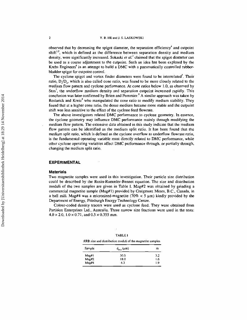
Materials Two magnetite samples were used in this investigation. Their particle size distribution could be described by the ~osin-~ammler- enn net equation. The size and distribution moduli of the two samples are given in Table I. Mag#2 was obtained by grinding a commercial magnetite sample (Mag#l) provided by Craigmont Mines, B.C., Canada, in a ball mill. Mag#4 was a micronized-magnetite (70% < 5 pm) kindly provided by the Department of Energy. Pittsburgh Energy Technology Centre.
Colour-coded density tracers were used as cyclone feed. They were obtained from Partition Enterprises Ltd., Australia. Three narrow size fractions were used in the tests: 4 . 0 ~ 2.0, l.Ox0.71, andO.Sx0.355 mm.
TABLE 1
KRB size and distribution moduli of the magnetite samples
Dow
nloa
ded
by [
Uni
vers
itaet
sbib
lioth
ek H
eide
lber
g] a
t 18:
29 1
4 N
ovem
ber
2014
DENSE MEDIUM CYCLONE PERFORMANCE 3
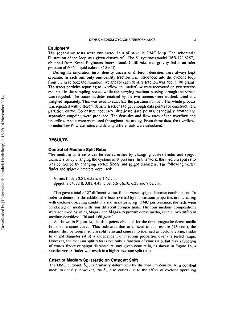
Equipment The separation tests were conducted in a pilot-scale DMC loop. The schematic illustration of the loop was given elsewherelo. The 6" cyclone (model D6B-12'-S287). obtained from Krebs Engineers International, California, was gravity-fed at an inlet pressure of 60.6" liquid column (10 x D).
During the separation tests, density tracers of different densities were always kept separate. In each run, only one density fraction was introduced into the cyclone loop from the head box; the minimum weight for each density fraction was about 100 grams. The tracer particles reporting to ovefflow and undefflow were recovered on two screens mounted in the sampling boxes, while the carrying medium passing through the screen was recycled. The tracer particles retained by the two screens were washed, dried and weighed separately. This was used to calculate the partition number. The whole process was repeated with different density fractions to get enough data points for constructing a partition curve. To ensure accuracy, duplicate data points, especially around the separation cutpoint, were produced. The densities and flow rates of the ovefflow and undefflow media were monitored throughout the testing. From these data, the ovefflow- to-underflow flowrate ratios and density differentials were calculated.
RESULTS
Control of Medium Split Ratio The medium split ratio can be varied either by changing vortex finder and spigot diameters or by changing the cyclone inlet pressure. In this work, the medium split ratio was controlled by changing vortex finder and spigot diameters. The following vortex finder and spigot diameters were used:
Vortex finder: 3.81,6.35 and 7.62 cm. Spigot: 2.54, 3.18, 3.81,4.45, 5.08, 5.64, 6.10, 6.35 and 7.62 cm.
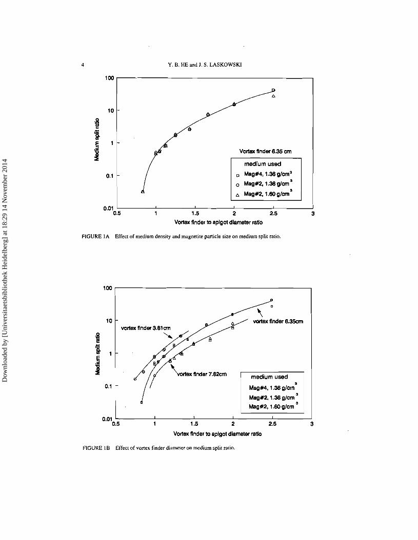
This gave a total of 27 different vortex finder versus spigot diameter combinations. In order to determine the additional effects exerted by the medium properties in interacting with cyclone operating conditions and in influencing DMC performance, the tests were conducted on media with four different compositions. The four medium compositions were achieved by using Mag#2 and Mag#4 to prepare dense media, each at two different medium densities: 1.36 and 1.60 g/cm3.
As shown in Figure la, the data points obtained for the three magnetite dense media fall on the same curve. This indicates that at a fixed inlet pressure (150 cm), the relationship between medium split ratio and cone ratio (defined as cyclone vortex finder to spigot diameter ratio) is independent of medium properties over the tested range. However, the medium split ratio is not only a function of cone ratio, but also a function of vortex finder or spigot diameter. At any given cone ratio, as shown in Figure Ib, a smaller vortex finder will result in a higher medium split ratio.
Effect of Medium Split Ratio on Cutpoint Shift The DMC cutpoint, S,, , is primarily determined by the medium density. At a constant medium density, however, the S,, also varies due to the effect of cyclone operating
Dow
nloa
ded
by [
Uni
vers
itaet
sbib
lioth
ek H
eide
lber
g] a
t 18:
29 1
4 N
ovem
ber
2014
4 Y. B. HE and J. S . LASKOWSKI
Vortex flnder 8.35 cm
Mag#4,1.36 glcm3
0 Mag#2,1.36 glcm
0.01 1 0.5 1 1.5 2 2.5 3
Vortex flnder to splgot diameter ratlo
FIGURE I A Effect of medium density and magnetite particle size on medium split ratio.
vortex flnder 3.81
rtex flnder 7.62cm
Mag#4,1.36 glcm
Mag#2,1.36 glcm
Mag#2,1 .M) glcm
0.01 1 I I I I I 0.6 1 1.5 2 2.5 3
Vortex finder to splgot diameter ratlo
FIGURE 1 B Effect of vortex finder diameter on medium split ratio.
Dow
nloa
ded
by [
Uni
vers
itaet
sbib
lioth
ek H
eide
lber
g] a
t 18:
29 1
4 N
ovem
ber
2014
DENSE MEDIUM CYCLONE PERFORMANCE 5
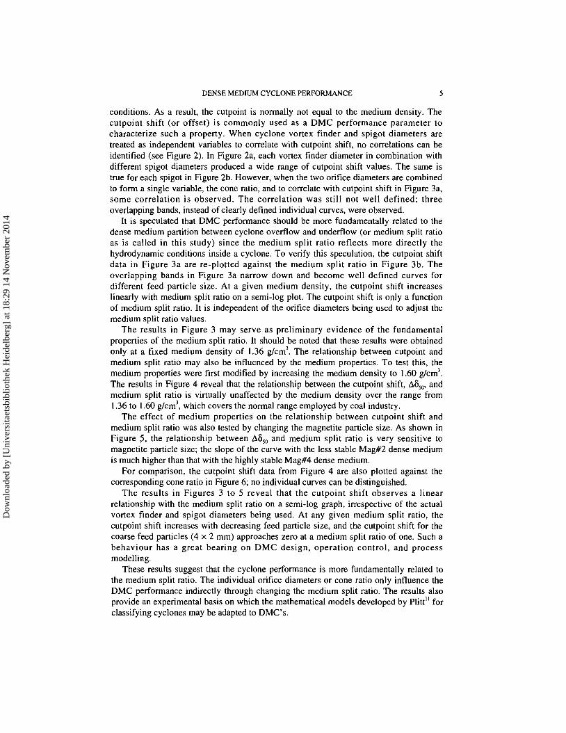
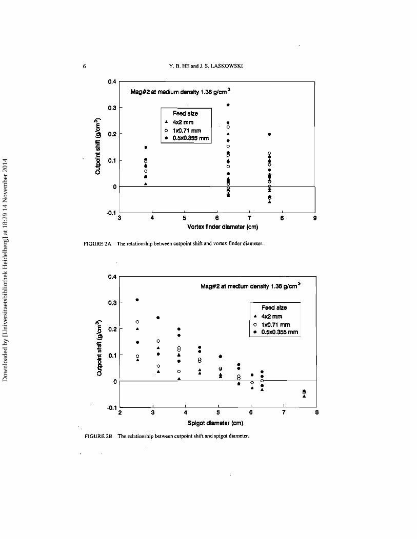
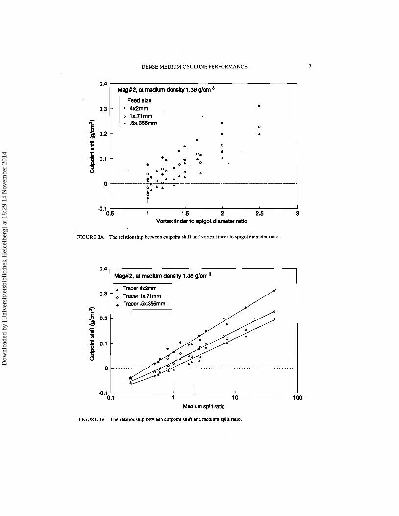
conditions. As a result, the cutpoint is normally not equal to the medium density. The cutpoint shift (or offset) is commonly used as a DMC performance parameter to characterize such a property. When cyclone vortex finder and spigot diameters are treated as independent variables to correlate with cutpoint shift, no correlations can be identified (see Figure 2). In Figure 2a, each vortex finder diameter in combination with different spigot diameters produced a wide range of cutpoint shift values. The same is true for each spigot in Figure 2b. However, when the two orifice diameters are combined to form a single variable, the cone ratio, and to correlate with cutpoint shift in Figure 3a, some correlation is observed. The correlation was still not well defined; three overlapping bands, instead of clearly defined individual curves, were observed.
It is speculated that DMC performance should be more fundamentally related to the dense medium partition between cyclone overflow and underflow (or medium split ratio as is called in this study) since the medium split ratio reflects more directly the hydrodynamic conditions inside a cyclone. To verify this speculation, the cutpoint shift data in Figure 3a are re-plotted against the medium split ratio in Figure 3b. The overlapping bands in Figure 3a narrow down and become well defined curves for different feed particle size. At a given medium density, the cutpoint shift increases linearly with medium split ratio on a semi-log plot. The cutpoint shift is only a function of medium split ratio. It is independent of the orifice diameters being used to adjust the medium split ratio values.
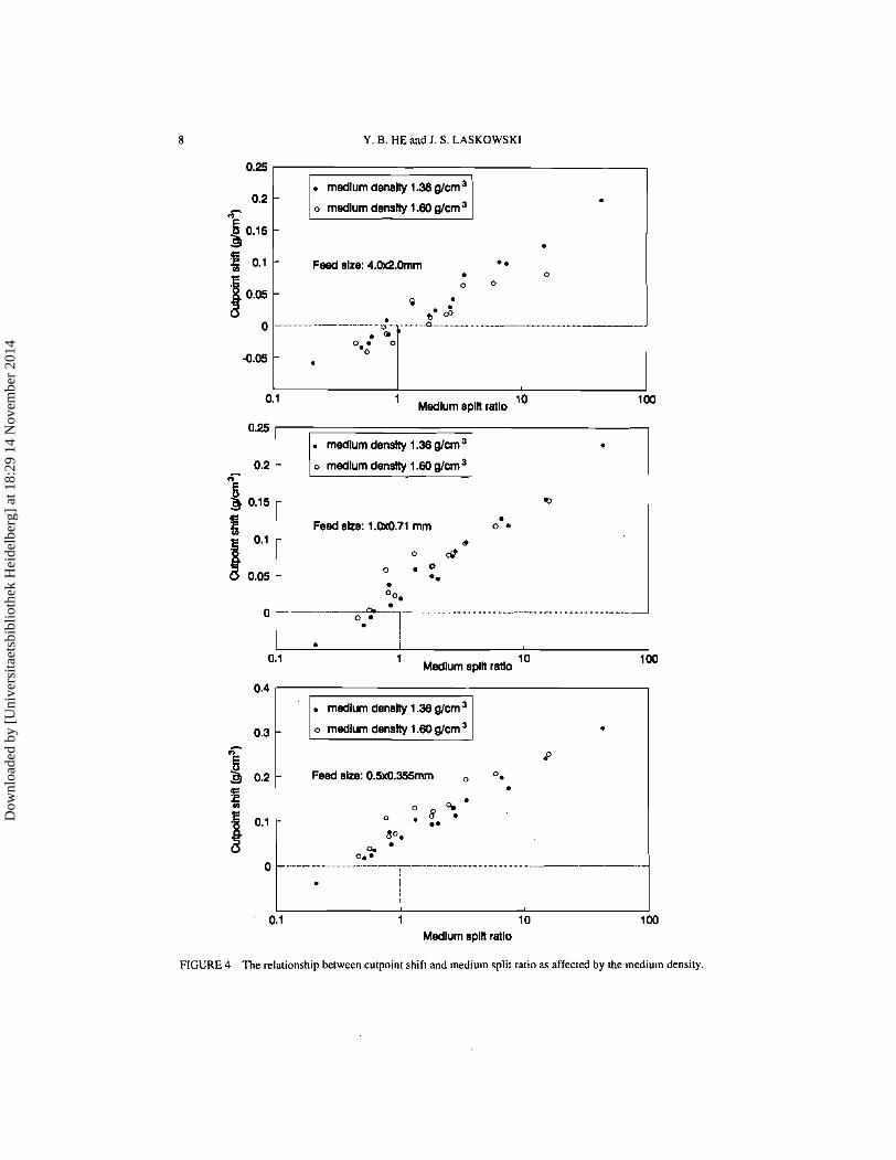
The results in Figure 3 may serve as preliminary evidence of the fundamental properties of the medium split ratio. It should be noted that these results were obtained only at a fixed medium density of 1.36 g/cml. The relationship between cutpoint and medium split ratio may also be influenced by the medium properties. To test this, the medium properties were first modified by increasing the medium density to 1.60 g/cml. The results in Figure 4 reveal that the relationship between the cutpoint shift, A&,, and medium split ratio is virtually unaffected by the medium density over the range from 1.36 to 1.60 g/cml, which covers the normal range employed by coal industry.
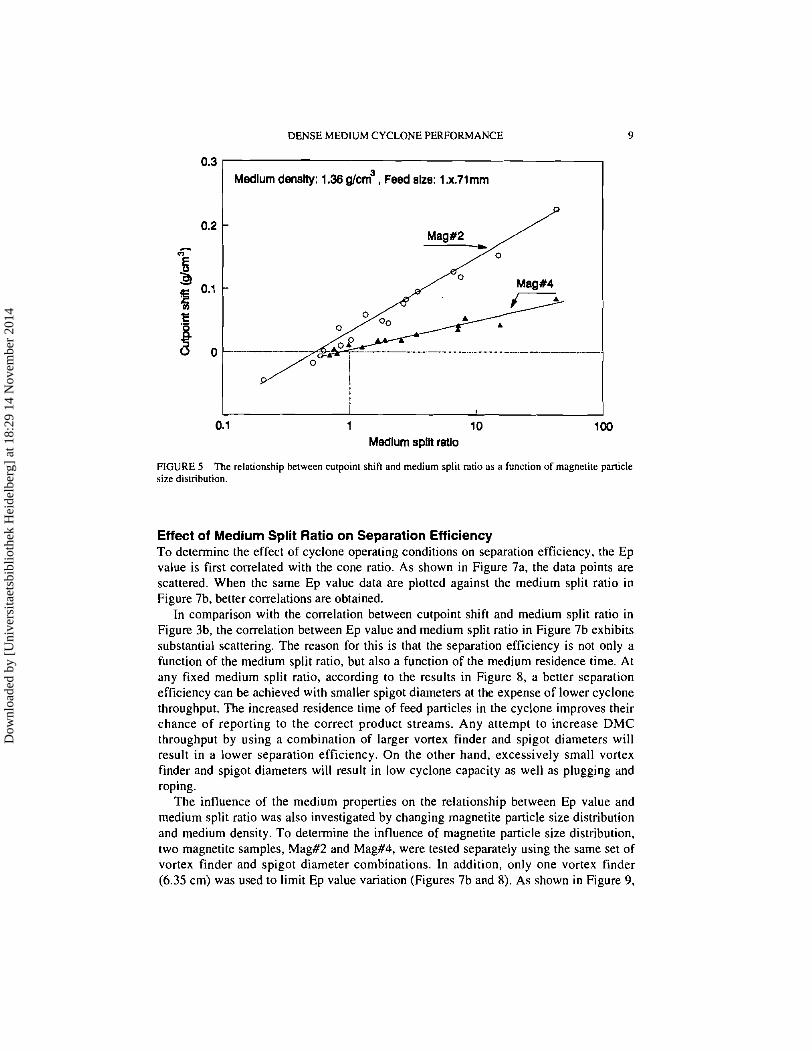
The effect of medium properties on the relationship between cutpoint shift and medium split ratio was also tested by changing the magnetite particle size. As shown in Figure 5, the relationship between A6,, and medium split ratio is very sensitive to magnetite particle size; the slope of the curve with the less stable Mag#2 dense medium is much higher than that with the highly stable Mag#4 dense medium.
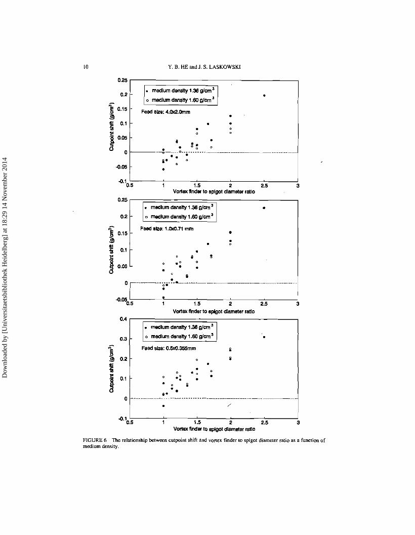
For comparison, the cutpoint shift data from Figure 4 are also plotted against the corresponding cone ratio in Figure 6; no individual curves can be distinguished.
The results in Figures 3 to 5 reveal that the cutpoint shift observes a linear relationship with the medium split ratio on a semi-log graph, irrespective of the actual vortex finder and spigot diameters being used. At any given medium split ratio, the cutpoint shift increases with decreasing feed particle size, and the cutpoint shift for the coarse feed particles (4 x 2 mm) approaches zero at a medium split ratio of one. Such a behaviour has a great bearing on DMC design, operation control, and process modelling.
These results suggest that the cyclone performance is more fundamentally related to the medium solit ratio. The individual orifice diameters or cone ratio onlv influence the DMC performance indirectly through changing the medium split ratio. The results also provide an experimental basis on which the mathematical models developed bv Plitt" for classifying cyclones may be adapted to DMC's.
Dow
nloa
ded
by [
Uni
vers
itaet
sbib
lioth
ek H
eide
lber
g] a
t 18:
29 1
4 N
ovem
ber
2014
Y. 8. HE and I. S . LASKOWSKI
I Mag#? a! medium density 1.36 gfcm
-0.1 1 3 4 5 8 7 8
Vortex flnder dlameter (cm)
FIGURE 2A The relationship between cutpoint shift and vortex finder diameter.
0.4
Mag#2 a! medlum denslty 1.38 gfcm
Splgot dlameter (cm)
FIGURE 2B The relationship between cutpoint shift and spigot diameter.
Dow
nloa
ded
by [
Uni
vers
itaet
sbib
lioth
ek H
eide
lber
g] a
t 18:
29 1
4 N
ovem
ber
2014
DENSE MEDIUM CYCLONE PERFORMANCE
0.4 ( Mag#2, at medlum denslty 1.38 g/cm
-0.1 0.5 1 1.5 2 2.5 3
Vortex flnder to splgot dlameter ratlo
FIGURE 3A The relationship between cutpoint shift and vortex finder to spigot diameter ratio.
Mag#2, at medlum denstty 1.38 g/cm
Tracer lx.71 mm
~..
-0.1 0.1 1 I 0 100
Medium split ratio
FIGURE 38 The relationship between cutpoint shift and medium split ratio.
Dow
nloa
ded
by [
Uni
vers
itaet
sbib
lioth
ek H
eide
lber
g] a
t 18:
29 1
4 N
ovem
ber
2014
8 Y . B. HEand I. S. LASKOWSKI
I 0.1
Medlurn spin ratio 10 1
0.25
o rnedlum density 1.60 glcm
0
0.2 - '--
Feed slze: 1 .OkQ.71 mm 0 8
e 0 d
0 . O *. OO.
.- -. . ---.- -.- -
I
. rnedlum deneity 1.38 glcm - o rnedlum density 1.60 glcrn a I
I 0.1 10
Medlurn spin ratlo
Medlurn spln ratio
0.4
0.3
5 3 0.2
E
FIGURE 4 The relationship between cutpoint shift and medium split ratio as affected by the medium density.
rnedlurn density 1.38 glcrn
- I o medium density 1.60 glcrn
P - Feed eke: 0.5x0.355rnm 0.
0 4 ' o . 8 .. do.
c. 0.
0 - - - - --- -- -- -- - - -- . - - I i I
0.1 1 10
Dow
nloa
ded
by [
Uni
vers
itaet
sbib
lioth
ek H
eide
lber
g] a
t 18:
29 1
4 N
ovem
ber
2014
DENSE MEDIUM CYCLONE PERFORMANCE
0.3 Medlum denslty: 1.36 g/cm3 , Feed slze: l.x.7lmm
1 10 Medium spln ratlo
FIGURE 5 The relationship between cutpoint shift and medium split ratio as a function of magnetite panicle size distribution.
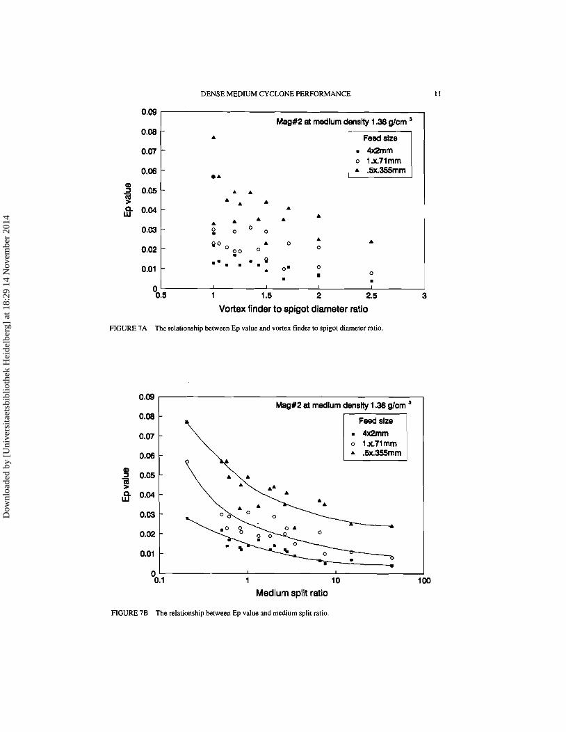
Effect of Medium Split Ratio on Separation Efficiency To determine the effect of cyclone operating conditions on separation efficiency, the Ep value is first correlated with the cone ratio. As shown in Figure 7a, the data points are scattered. When the same Ep value data are plotted against the medium split ratio in Figure 7b, better correlations are obtained.
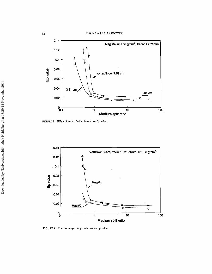
In comparison with the correlation between cutpoint shift and medium split ratio in Figure 3b, the correlation between Ep value and medium split ratio in Figure 7b exhibits substantial scattering. The reason for this is that the separation efficiency is not only a function of the medium split ratio, but also a function of the medium residence time. At any fixed medium split ratio, according to the results in Figure 8, a better separation efficiency can be achieved with smaller spigot diameters at the expense of lower cyclone throughput. The increased residence time of feed particles in the cyclone improves their chance of reporting to the correct product streams. Any attempt to increase DMC throughput by using a combination of larger vortex finder and spigot diameters will result in a lower separation efficiency. On the other hand, excessively small vortex finder and spigot diameters will result in low cyclone capacity as well as plugging and roping.
The influence of the medium properties on the relationship between Ep value and medium split ratio was also investigated by changing magnetite particle size distribution and medium density. To determine the influence of magnetite particle size distribution, two magnetite samples, Mag#2 and Mag#4, were tested separately using the same set of vortex finder and spigot diameter combinations. In addition, only one vortex finder (6.35 cm) was used to limit Ep value variation (Figures 7b and 8). As shown in Figure 9,
Dow
nloa
ded
by [
Uni
vers
itaet
sbib
lioth
ek H
eide
lber
g] a
t 18:
29 1
4 N
ovem
ber
2014
Y. B. HE and J. S. LASKOWSKI
medlum denslty 1.36 g/cm3
o medlum denstty 1.60 g/cm
b
Vortex Under to splgot dlameter ratlo
- . 0 L
0. . 4.05 *
0.5 1 1.5 2 2.5 Vortex Under to spigot dlameter ratlo
. "ii
Feed ake: 0.5x0.355mm 8
3 0.2 - 0 a
5 .
0 O * . a
B - * : . * o 8
e * 0 --- - - -- -- --- -- - -- - . /
. 0.2 o medlum denatty 1.60 g/cm3
0.15 - Feed size: 1 . 0 . 7 1 mm
FIGURE 6 The relationship between cutpoint shift and vortex finder to spigot diameter ratio as a function of medium density.
b 0.1
fj 0.05
. -
. . 0 0 a
- 0 .O 0 . .
n
Dow
nloa
ded
by [
Uni
vers
itaet
sbib
lioth
ek H
eide
lber
g] a
t 18:
29 1
4 N
ovem
ber
2014
DENSE MEDIUM CYCLONE PERFORMANCE
Mag#2 at rnedlurn denslty 1.36 g/cm a 0.08
A
0.07 1 Feed slze
o 1.x71rnrn 0.06
A
Vortex finder to spigot diameter ratio
FIGURE 7A The relationship between Ep value and vortex finder to spigot diameter ralio
0.09 MagX2 at rnedlurn denstty 1.36 g/cm '
Feed slze
o i.x.7irnrn
Medium split ratio
FIGURE 7B The relationship between Ep value and medium split ratio.
Dow
nloa
ded
by [
Uni
vers
itaet
sbib
lioth
ek H
eide
lber
g] a
t 18:
29 1
4 N
ovem
ber
2014
Y. B. HE and J. S . LASKOWSKI
1 '0, Medium split ratio
Mag #4. at 1.36 g/cm3, tracer 1 .x.71 mm
FIGURE 8 Effect of vonex kinder diameter on Ep value.
b'
Vortex=6.35cm, tracer 1.0x0.71 mm, at 1.36 g/cm3
D
I
1 10
Medium split ratio
vortex flnder 7.62 cm - 6.35 cm r- .,
FIGURE 9 Effect of magnetite particle size an Ep value.
Dow
nloa
ded
by [
Uni
vers
itaet
sbib
lioth
ek H
eide
lber
g] a
t 18:
29 1
4 N
ovem
ber
2014
DENSE MEDIUM CYCLONE PERFORMANCE I3
at any given medium split ratio and medium density, the magnetite particle size distribution does not affect the general relationship between Ep value and medium split ratio. The curve only shifts slightly to a higher position when the Mag#4 dense medium is employed. A considerable increase in Ep value occurs only when the medium split ratio is below one, which, as will be discussed later, is out of the normal operation range.
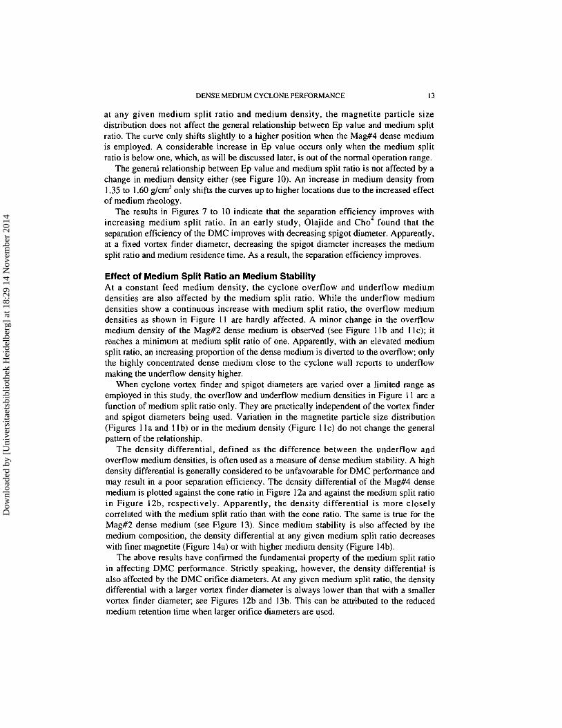
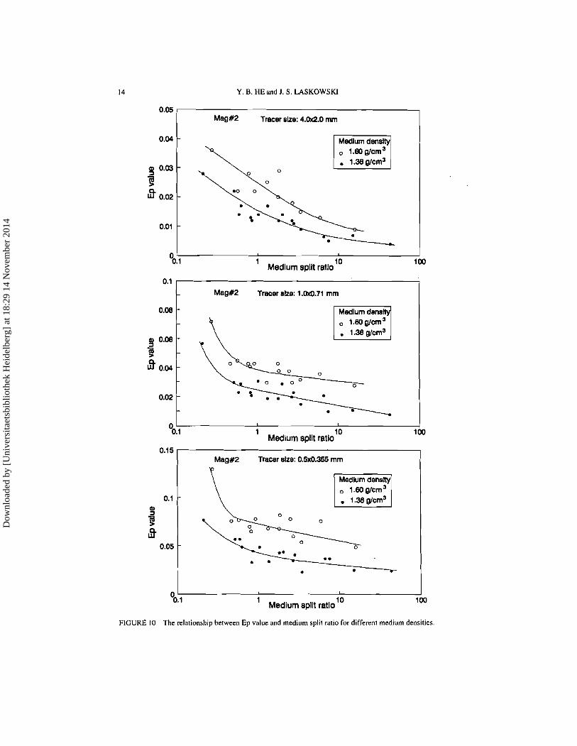
The general relationship between Ep value and medium split ratio is not affected by a change in medium density either (see Figure 10). An increase in medium density from 1.35 to 1.60 g/cm3 only shifts the curves up to higher locations due to the increased effect of medium rheology.
The results in Figures 7 to 10 indicate that the separation efficiency improves with increasing medium split ratio. In an early study, Olajide and Cho4 found that the separation efficiency of the DMC improves with decreasing spigot diameter. Apparently, at a fixed vortex finder diameter, decreasing the spigot diameter increases the medium split ratio and medium residence time. As a result, the separation efficiency improves.
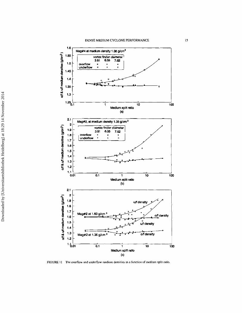
Effect of Medium Split Ratio an Medium Stability At a constant feed medium density, the cyclone overflow and underflow medium densities are also affected by the medium split ratio. While the underflow medium densities show a continuous increase with medium split ratio, the overflow medium densities as shown in Figure 11 are hardly affected. A minor change in the overflow medium density of the Mag#2 dense medium is observed (see Figure I l b and I lc); it reaches a minimum at medium split ratio of one. Apparently, with an elevated medium split ratio, an increasing proportion of the dense medium is diverted to the overflow; only the highly concentrated dense medium close to the cyclone wall reports to underflow making the underflow density higher.
When cyclone vortex finder and spigot diameters are varied over a limited range as employed in this study, the overflow and underflow medium densities in Figure 11 are a function of medium split ratio only. They are practically independent of the vortex finder and spigot diameters being used. Variation in the magnetite particle size distribution (Figures I l a and I Ib) or in the medium density (Figure I lc) do not change the general pattern of the relationship.
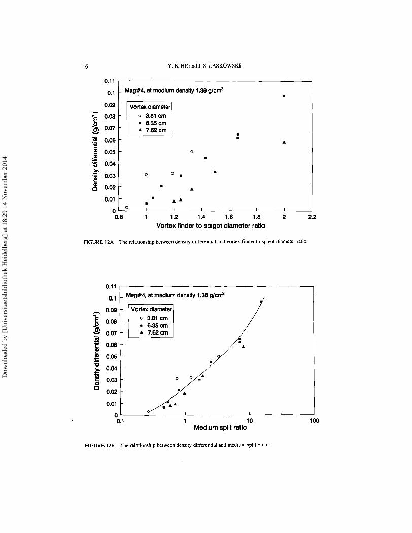
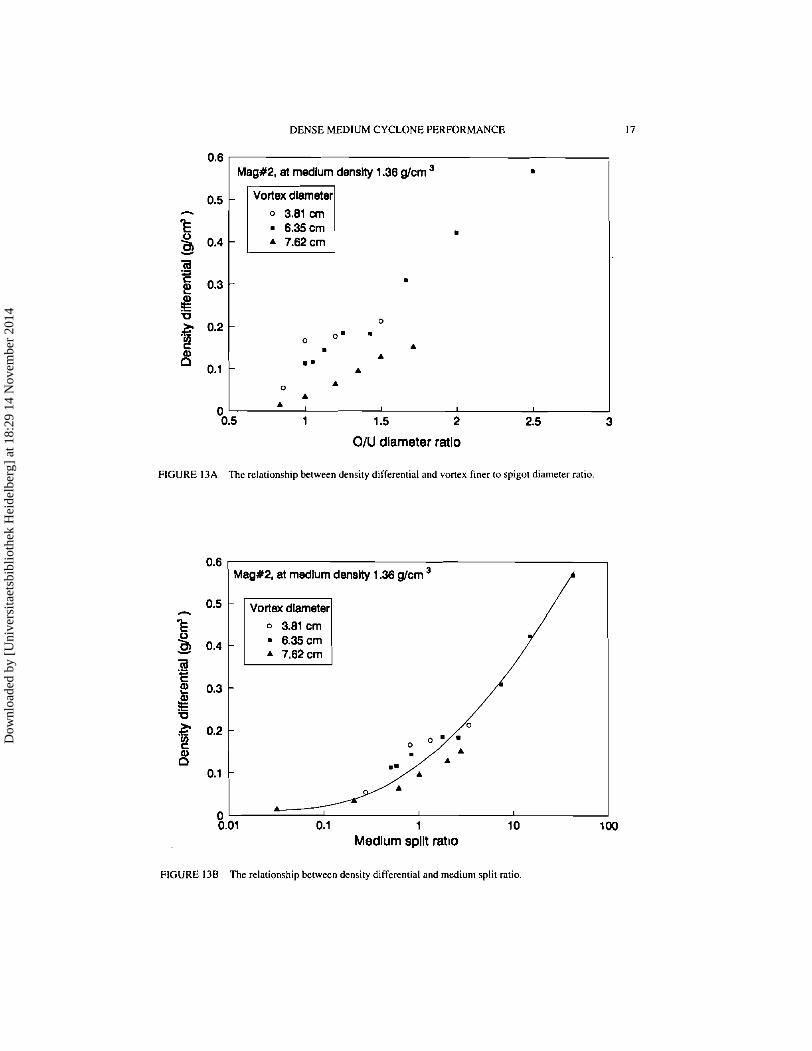
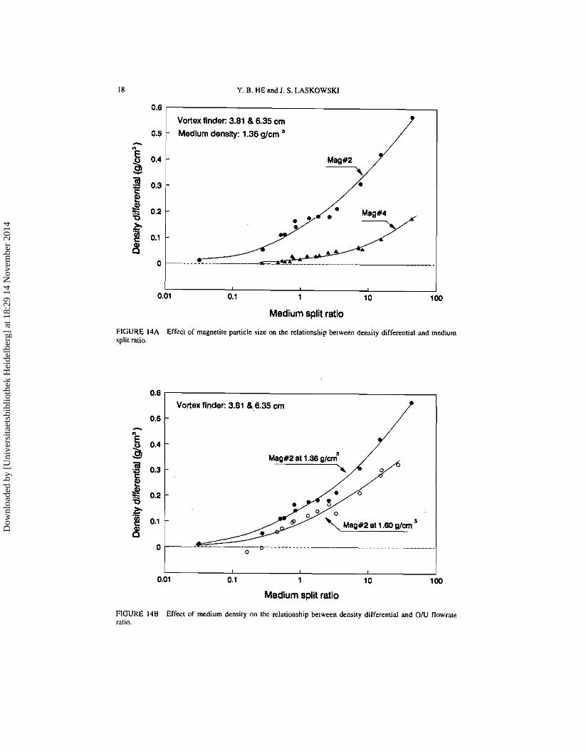
The density differential, defined as the difference between the underflow and overflow medium densities, is often used as a measure of dense medium stability. A high density differential is generally considered to be unfavourable for DMC performance and may result in a poor separation efficiency. The density differential of the Mag#4 dense medium is plotted against the cone ratio in Figure 12a and against the medium split ratio in Figure 12b, respectively. Apparently, the density differential is more closely correlated with the medium split ratio than with the cone ratio. The same is true for the Mag#:! dense medium (see Figure 13). Since medium stability is also affected by the medium composition, the density differential at any given medium split ratio decreases with finer magnetite (Figure 14a) or with higher medium density (Figure 14b).
The above results have confirmed the fundamental property of the medium split ratio in affecting DMC performance. Strictly speaking, however, the density differential is also affected by the DMC orifice diameters. At any given medium split ratio, the density differential with a larger vortex finder diameter is always lower than that with a smaller vortex finder diameter; see Figures 12b and 13b. This can be attributed to the reduced medium retention time when larger orifice diameters are used.
Dow
nloa
ded
by [
Uni
vers
itaet
sbib
lioth
ek H
eide
lber
g] a
t 18:
29 1
4 N
ovem
ber
2014
Y. B. HE and J. S. LASKOWSKl
0.05 Mag#2 Tracer eke: 4.0w2.0 mm
I
O0:l 1 10 1 Medium split ratlo
Mag+2 Tracer eke: 1 .(h8.71 mm
Medium dens
- O0.l 1 10 1
Medlum split ratio 0.15
Mag#2 Tracer eke: 0.5~0.355 mm
Medlum den
0.1 - m
3 0.05
. 00!1 1 10
Medium split ratio
FIGURE 10 The relationship between Ep value and medium split ratio for different medium densities.
Dow
nloa
ded
by [
Uni
vers
itaet
sbib
lioth
ek H
eide
lber
g] a
t 18:
29 1
4 N
ovem
ber
2014
DENSE MEDIUM CYCLONE PERFORMANCE
1.6 - Mag#4 at medium density 1.38 &m3 3 1.55 - vortex finder diameter 3 3.81 6.35 7.62 $ 1.5 - overtiow 1
underflow a
1.45 - 0
5 1.4- P
1.35 -
1 10 1 Medium spln ratio
(a)
2.1 MagY2, at medium density 1.38 @om3
2 - vortex finder diameter 3.81 6.35 7.62 6 8 ::I
1 1.7- 8 1.6-
5 1.5-
1.4-
3 1.3- 6
6 1.2-
Medium spin ratio ('4
0.1 1 10 Medlurn apin ratlo
(c)
FIGURE I I The overflow and underflow medium densities as a function of medium split ratio.
Dow
nloa
ded
by [
Uni
vers
itaet
sbib
lioth
ek H
eide
lber
g] a
t 18:
29 1
4 N
ovem
ber
2014
Y. B. HE and J. S. LASKOWSKI
0.1 1
O.l Mag#4, at medium density 1.38 g/cm3 9
Vortex diameter 0 3.81 cm = 8.35cm * 7.62cm
J - 0.8 1 1.2 1.4 1 .8 I .8 2 2.2
Vortex finder to splgot diameter ratio
FIGURE IZA The relationship between density differential and vortex finder to spigot diameter ratio.
Mag#4, at medium density 1.38 g/cm3
" 0.1 1 10
Medium split ratio
FIGURE 128 The relationship between density differential and medium split ratio.
Dow
nloa
ded
by [
Uni
vers
itaet
sbib
lioth
ek H
eide
lber
g] a
t 18:
29 1
4 N
ovem
ber
2014
DENSE MEDIUM CYCLONE PERFORMANCE
Mag#2, at medium density 1.36 g/cm
A 7.62 cm
OIU diameter ratio
FIGURE 13A The relationship between density differential and vortex finer to spigot diameter ratio.
0.6 Mag#2, at medlum denslty 1.36 g/cm
/ Vortex dlameter
0 3.81 cm
A 7.62 cm
0 I
0.01 0.1 1 10 Medium split ratio
FIGURE 138 The relationship between density differential and medium split ratio
Dow
nloa
ded
by [
Uni
vers
itaet
sbib
lioth
ek H
eide
lber
g] a
t 18:
29 1
4 N
ovem
ber
2014
Y. B. HE and I. S. LASKOWSKI
Vortex finder: 3.81 8 6.35 cm
Medium density: 1.36 g/cm
Mag#2
Medium split ratio
FIGURE 14A Effect of magnetite particle size on the relationship between density differential and medium split mtio.
Vortex finder: 3.81 8 6.35 cm
L I I
0.01 0.1 1 10
Medium split ratio
FIGURE 148 Effect of medium density on the relationship between density differential and O N flowrate ratio.
Dow
nloa
ded
by [
Uni
vers
itaet
sbib
lioth
ek H
eide
lber
g] a
t 18:
29 1
4 N
ovem
ber
2014
DENSE MEDIUM CYCLONE PERFORMANCE
DISCUSSION
Control Range of Medium Split Ratio As shown in Figures 7 to 10, a better separation efficiency can be achieved with a higher medium split ratio. However, an excessively high medium split ratio may exert an adverse effect on DMC performance. To determine the optimum working range of medium split ratio, it is necessary to explore the two extreme conditions when the DMC runs at very low and high medium split ratios.
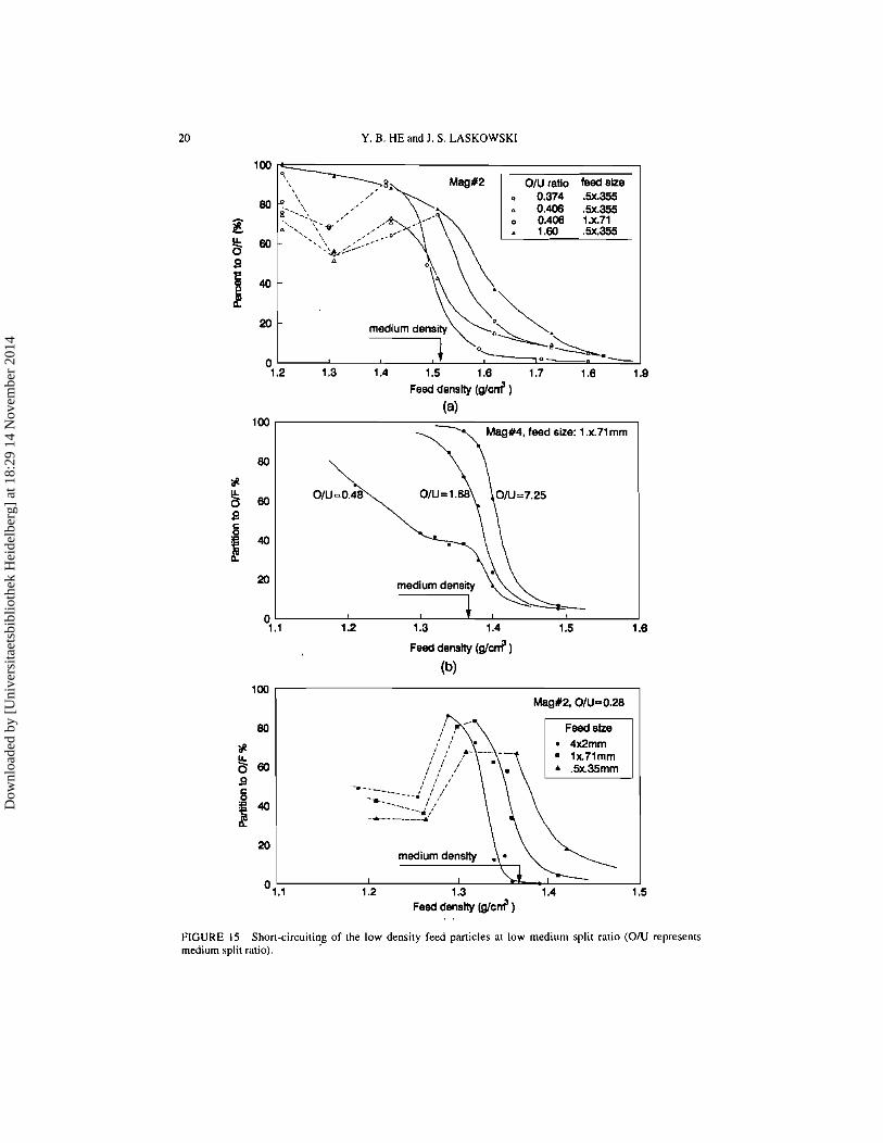
The phenomenon associated with a low medium split ratio is short-circuiting to underflow. When short circuiting occurs, part of the cyclone feed reports directly to the underflow stream without going through the separation process. This is illustrated in Figure 15, in which the partition numbers of low density materials level off or even fall. From Figure 1, it can be found that short-circuiting is affected by two major factors: medium split ratio and feed particle size. Shortcircuiting occurs at medium split ratios much lower than one and deteriorates as the medium split ratio decreases. The most severe short circuiting in this study occurred when the medium split ratio came down to 0.28 in Figure 15c. Short-circuiting is also sensitive to the effect of feed particle size. As shown in Figures 15a and 15c, it became increasingly serious when feed particle size decreased from 4 x 2 mm down to 0.5 x 0.355 mm.
On the other hand, an excessively high medium split ratio also causes a series of problems, mainly undefflow roping and spigot plugging. A high medium split ratio is normally accompanied by a prolonged residence time of the near-density materials in a DMC. When the content of the near-density materials in feed is low, is does not pose a serious problem. In the presence of a large proportion of near-density materials, the long residence time leads to their build-up inside the cyclone. Under normal cyclone operating conditions, an air cone exists along the cyclone axis, and a spraying discharge pattern for underflow should be observed. A phenomenon of intermittent flow pattern was widely reported5.'2.'3 due to the build-up of near-density materials. The normal spraying discharge was periodically interrupted by a rope-like discharge flow pattern. Sokaski and GeerI2 explained that the near-density particles, which cannot penetrate the high-density downward-flow medium, migrate towards the axis of the cyclone into the upward- flowing medium. While being too heavy to be carried away by the low-density upward- flow medium, these particles become entrapped in the eddy current adjacent to the spigot until a sufficient amount is accumulated resulting in congestion and an eventual breakdown of the medium flow pattern. The internal pressure then forces the accumulated near-density materials out of the spigot causing cyclone roping (or surging), followed by the re-establishment of the cyclone flow pattern, and the repetition of the whole process. Thus, an intermittent cyclone flow pattern is observed. Such an intermittent, roping discharge flow pattern is characteristic for a DMC treating coal with a high proportion of near-density materials at a high density differential. An elevated medium split ratio increases not only the density differential (Figures 12 to 14) but also the medium retention time. Thus, an excessively high medium split ratio should be avoided.
Plugging of the DMC may occur as a consequence of the high-density material build- up. As observed in our full scale test at Bullmoose Operating Corp. on a 680 mm DMC circuit, the DMC spigot was frequently plugged when processing a particular coal seam which contained a large percentage of high density materials (> 1.6 g/cm3). The problem
Dow
nloa
ded
by [
Uni
vers
itaet
sbib
lioth
ek H
eide
lber
g] a
t 18:
29 1
4 N
ovem
ber
2014
Y. B. HE and J. S. LASKOWSKI
100
OIU ratio bed she 0.374 SX.355
20 - rned~um densrty
0 O-*
1.2 1.3 1.4 1.5 1 .8 1.7 1 .8 Feed density (glad )
(4 Mag#4, feed size: 1 .x.71 mrn
Feed density (g/cm3)
(b)
% * Ell I
I I
01.1 1.2 1.3 1.4 Feed denstty (glen? )
. .
FIGURE 15 Short-circuiting of the low density feed particles at low medium split ratio ( O N represents medium split ratio).
Dow
nloa
ded
by [
Uni
vers
itaet
sbib
lioth
ek H
eide
lber
g] a
t 18:
29 1
4 N
ovem
ber
2014
DENSE MEDIUM CYCLONE PERFORMANCE 2 1
was aggravated after the 200 mm spigot was replaced by a smaller 180 mm spigot. During the plugging, the entire medium and feed bypassed the cyclone through the vortex finder. The circuit had to be shut down to remove the plugged high density materials.
According to the above analyses, the medium split ratio should not be lower than 1.0 to prevent the DMC from short-circuiting. Although it is beneficial to use higher medium split ratios to achieve a better separation efficiency (Figures 7 to 10). the improvement in Ep value at a medium split ratio above 4.0 is minimal. In addition, the possibility of an intermittent roping discharge flow pattern and plugging at a high medium split ratio is substantially increased. It is recommended that the value of the medium split ratio be close to that of the concentrate-to-refuse output ratio, so that the product-to-medium ratios in the overflow and underflow streams are about the same. In the case of coal separation, refuse accounts for 20% to 50% of the feed volume. This translates into an medium split ratio range of 1.0 to 4.0. Based on industrial practice and the conclusions obtained in this project, the optimum medium split ratio range is narrowed down to 2.0 i 0.5.
Applications of Medium Split Ratio Control The findings on the fundamental properties of the medium split ratio in DMC separation can lead to a wide array of practical applications in cyclone modelling, operation control, optimization, and design.
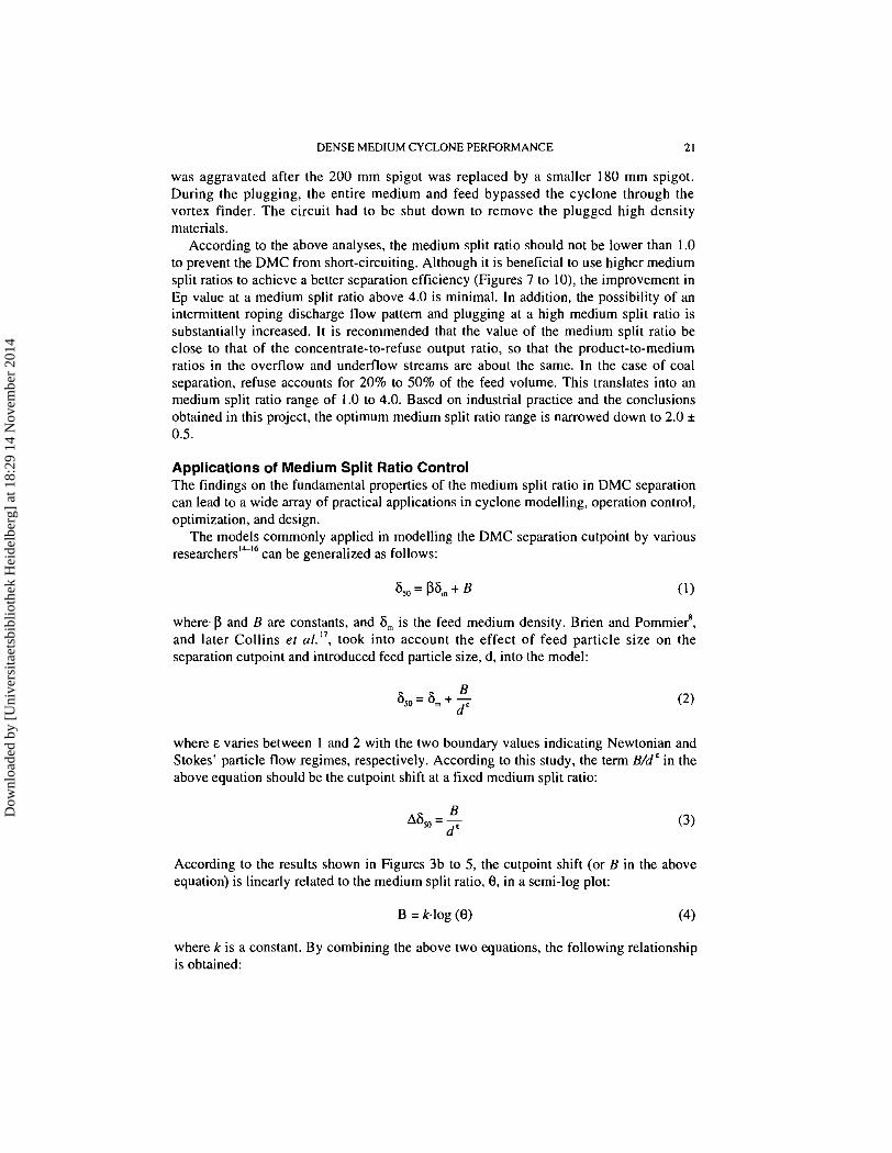
The models commonly applied in modelling the DMC separation cutpoint by various researchers'"16 can be generalized as follows:
where p and B are constants, and 6, is the feed medium density. Brien and ~ommie?, and later Collins et a/.", took into account the effect of feed particle size on the separation cutpoint and introduced feed particle size, d, into the model:
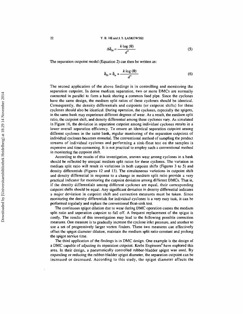
where E varies between 1 and 2 with the two boundary values indicating Newtonian and Stokes' particle flow regimes, respectively. According to this study, the term B/dC in the above equation should be the cutpoint shift at a fixed medium split ratio:
According to the results shown in Figures 3b to 5, the cutpoint shift (or B in the above equation) is linearly related to the medium split ratio, 8, in a semi-log plot:
where k is a constant. By combining the above two equations, the following relationship is obtained:
Dow
nloa
ded
by [
Uni
vers
itaet
sbib
lioth
ek H
eide
lber
g] a
t 18:
29 1
4 N
ovem
ber
2014
Y. B. HE and I. S. LASKOWSKI
The separation cutpoint model (Equation 2) can then be written as:
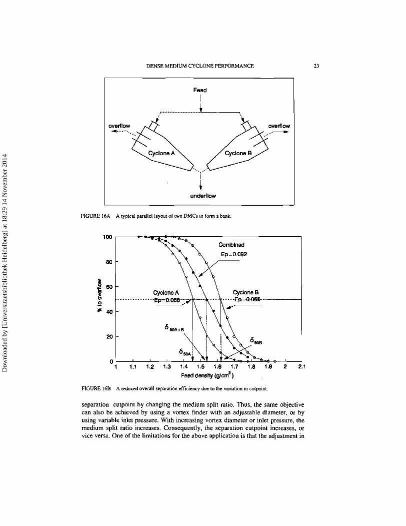
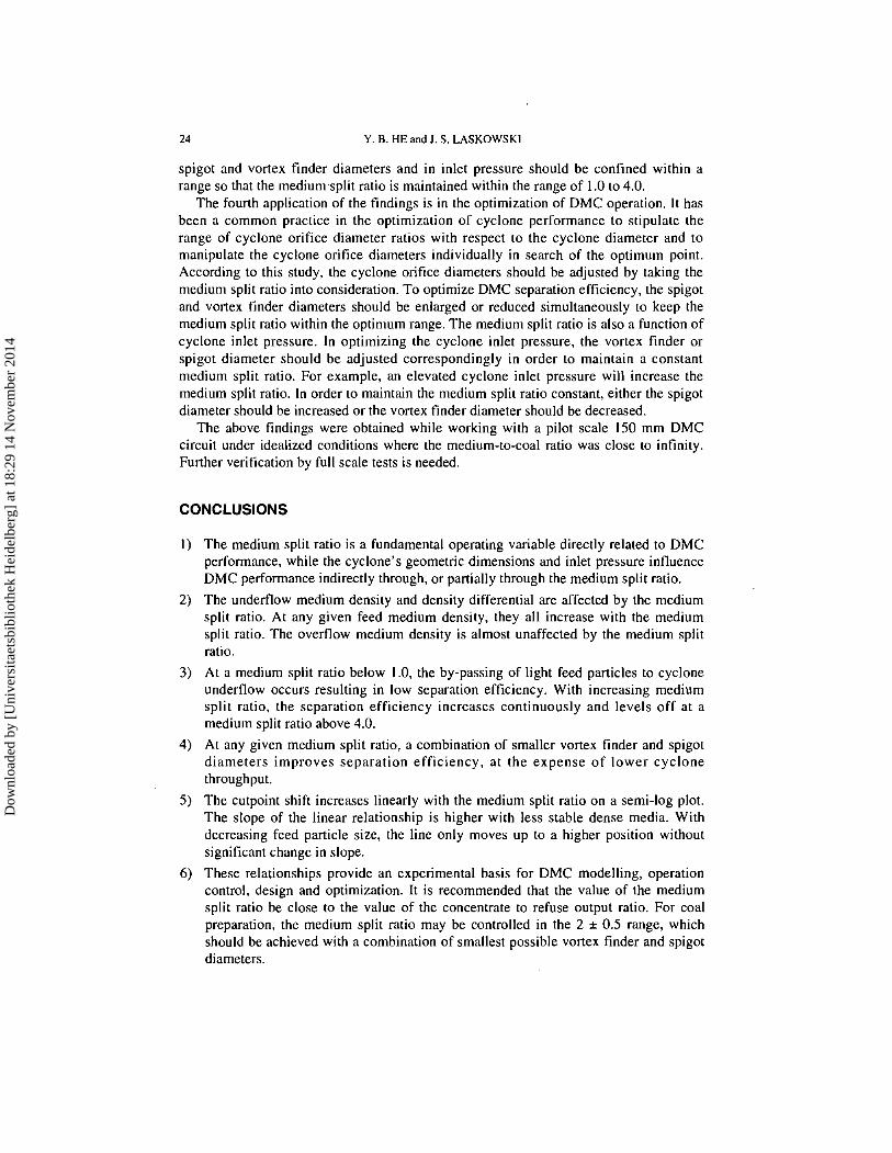
The second application of the above findings is in controlling and monitoring the separation cutpoint. In dense medium separation, two or more DMCs are normally connected in parallel to form a bank sharing a common feed pipe. Since the cyclones have the same design, the medium split ratios of these cyclones should be identical. Consequently, the density differentials and cutpoints (or cutpoint shifts) for these cyclones should also be identical. During operation, the cyclones, especially the spigots, in the same bank may experience different degrees of wear. As a result, the medium split ratio, the cutpoint shift, and density differential among these cyclones vary. As simulated in Figure 16, the deviation in separation cutpoint among individual cyclones results in a lower overall separation efficiency. To ensure an identical separation cutpoint among different cyclones in the same bank, regular monitoring of the separation cutpoints of individual cyclones becomes essential. The conventional method of sampling the product streams of individual cyclones and performing a sink-float test on the samples is expensive and time-consuming. It is not practical to employ such a conventional method in monitoring the cutpoint shift.
According to the results of this investigation, uneven wear among cyclones in a bank should be reflected by unequal medium split ratios for these cyclones. The variation in medium split ratio will result in variations in both cutpoint shifts (Figures 3 to 5) and density differentials (Figures 12 and 13). The simultaneous variations in cutpoint shift and density differential in response to a change in medium split ratio provide a very practical indicator for monitoring the cutpoint deviation among different DMCs. That is, if the density differentials among different cyclones are equal, their corresponding cutpoint shifts should be equal. Any significant deviation in density differential indicates a major deviation in cutpoint shift and correction measures must be taken. Since monitoring the density differentials for individual cyclones is a very easy task, it can be performed regularly and replace the conventional float-sink test.
The continuous spigot dilation due to wear during DMC operation causes the medium split ratio and seperation cutpoint to fall off. A frequent replacement of the spigot is costly. The results of this investigation may lead to the following possible correction measures. One measure is to gradually increase the cyclone inlet pressure, and another to use a set of progressively larger vortex finders. These two measures can effectively offset the spigot diameter dilation, maintain the medium split ratio constant and prolong the spigot service time.
The third application of the findings is in DMC design. One example is the design of a DMC capable of adjusting its separation cutpoint. Krebs Engineers6 have explored this area. In their design, a pneumatically controlled rubber-bladder spigot was used. By expanding or reducing the rubber-bladder spigot diameter, the separation cutpoint can be increased or decreased. According to this study, the spigot diameter affects the
Dow
nloa
ded
by [
Uni
vers
itaet
sbib
lioth
ek H
eide
lber
g] a
t 18:
29 1
4 N
ovem
ber
2014
DENSE MEDIUM CYCLONE PERFORMANCE
Feed
I C- r---- 7
overflow
underflow
16A A typical parallel layout of two DMCs to form a bank.
- - E p = O G - - - - - - 7
1 1.1 1.2 1.3 1.4 1.5 1.6 1.7 1.8 1.9 2 2.1
Feed densby (g/crn3 )
FIGURE 168 A reduced overall separation efficiency due to the variation in cutpoint
separation cutpoint by changing the medium split ratio. Thus, the same objective can also be achieved by using a vortex finder with an adjustable diameter, or by using variable inlet pressure. With increasing vortex diameter or inlet pressure, the medium split ratio increases. Consequently, the separation cutpoint increases, or vice versa. One of the limitations for the above application is that the adjustment in
Dow
nloa
ded
by [
Uni
vers
itaet
sbib
lioth
ek H
eide
lber
g] a
t 18:
29 1
4 N
ovem
ber
2014
24 Y. B. HE and J. S. LASKOWSKI
spigot and vortex finder diameters and in inlet pressure should be confined within a range so that the mediumsplit ratio is maintained within the range of 1.0 to 4.0.
The fourth application of the findings is in the optimization of DMC operation. It has been a common practice in the optimization of cyclone performance to stipulate the range of cyclone orifice diameter ratios with respect to the cyclone diameter and to manipulate the cyclone orifice diameters individually in search of the optimum point. According to this study, the cyclone orifice diameters should be adjusted by taking the medium split ratio into consideration. To optimize DMC separation efficiency, the spigot and vortex finder diameters should be enlarged or reduced simultaneously to keep the medium split ratio within the optimum range. The medium split ratio is also a function of cyclone inlet pressure. In optimizing the cyclone inlet pressure, the vortex finder or spigot diameter should be adjusted correspondingly in order to maintain a constant medium split ratio. For example, an elevated cyclone inlet pressure will increase the medium split ratio. In order to maintain the medium split ratio constant, either the spigot diameter should be increased or the vortex finder diameter should be decreased.
The above findings were obtained while working with a pilot scale 150 mm DMC circuit under idealized conditions where the medium-to-coal ratio was close to infinity. Further verification by full scale tests is needed.
CONCLUSIONS
The medium split ratio is a fundamental operating variable directly related to DMC performance, while the cyclone's geometric dimensions and inlet pressure influence DMC performance indirectly through, or partially through the medium split ratio.
The underflow medium density and density differential are affected by the medium split ratio. At any given feed medium density, they all increase with the medium split ratio. The overflow medium density is almost unaffected by the medium split ratio.
At a medium split ratio below 1.0, the by-passing of light feed particles to cyclone underflow occurs resulting in low separation efficiency. With increasing medium split ratio, the separation efficiency increases continuously and levels off at a medium split ratio above 4.0.
At any given medium split ratio, a combination of smaller vortex finder and spigot diameters improves separation efficiency, at the expense of lower cyclone throughput.
The cutpoint shift increases linearly with the medium split ratio on a semi-log plot. The slope of the linear relationship is higher with less stable dense media. With decreasing feed particle size, the line only moves up to a higher position without significant change in slope.
These relationships provide an experimental basis for DMC modelling, operation control, design and optimization. It is recommended that the value of the medium split ratio be close to the value of the concentrate to refuse output ratio. For coal preparation, the medium split ratio may be controlled in the 2 i 0.5 range, which should be achieved with a combination of smallest possible vortex finder and spigot diameters.
Dow
nloa
ded
by [
Uni
vers
itaet
sbib
lioth
ek H
eide
lber
g] a
t 18:
29 1
4 N
ovem
ber
2014
DENSE MEDIUM CYCLONE PERFORMANCE
Acknowledgements
Financial suppon for this research was provided by the Science Council of British Columba
References
I. P. Beluaou and S. de Chawlowski, "Experimental Study of the Cyclone Washer". Proc. In,. Conf on Coal prep., Paris. France. 1950, pp. YZ&k? 1.
2. J . P. Matonev. "The Washinc Cvclone". Int. Pubiicarion of the Soecial Aonaratus Division. Hevl and - , . , Patterson, lnc., 1962, pp. 1-6.
3. M. Sokaski, M. R. Geer and W. L. McNorris, "The Wet concentration of Fine Coal: Dense Medium Separation", in I. W. Leonard, (ed). Coal Preparation. 4th Edition, ACME, New York. 1979.
4. 0 . Olajide and E. H. Cho. "A Laboratory Study on Dense Medium Cycloning", Min. & Mefall. Proc., 49-55 (February 1989).
5. A. W. Deurbrouck and J. Hudy, "Performance Characteristics of Coal-Washing Equipment: Dense- Medium Cyclones", U . S. Bureau of Mines R17673 (1972).
6. R. G. Moorhead, "The Use of a Variable-Diameter Apex in Controlling Heavy-Media Cyclone Operation", Coal Prep'91 Conference, Lexington, 1991, pp. 143-167.
7. M. Stas. 'The Influence of the Orifices on the Washing Characteristics of the Hydrocyclone". Proc. 4th 1111. Mineral Dressing Congr., Stockholm, 1957, pp. 161-192.
8. F. B. Brien and L. W. Pommier. "Results of An lnvestigalion of the Use of Heavy Liquids in a Cyclone for Concentrating Values From Tin Ores". Trans. AIME, 229,335-341 (1964).
9. C. J. Restarick and 2. Kmic, "The Effect of Underflow to Overflow Ratio on Dense Medium Cyclone Operation", Mineral Engineering, 4.263-270 (1991).
10. Y. B. He and J. S. Laskowski, "Effect of Dense Medium Properties on the Separation Performance of a Dense Medium Cyclone", Mineral Engineering, 7,209-221 (1994).
11. L. R. Plitt, "A Mathematical Model of the Hydrocylone Classifier". C I M Bull., (Dec. 1976). pp. 114-123 (1976).
12. M. Sokaski and M. R. Geer. "Cleaning Unsized Fine Coal in a Dense Medium Cyclone Pilot Plant", U. S. Bureau of Mines RI6274 (1963).
13. J . J. Davis. "A Study of Coal Washing Dense Medium Cyclone", PhD Thesis, University of Queensland. 1989.
14. J. J. Napier-Munn, "Influence of Medium Viscosity on the Density Separation of Minerals in Cyclones", in Proc. Inr. Canj: on Hydrocyclones, Cambridge, U. K. 1980, pp. 63-82.
15. I. A. Scott and T. J. Napier-Munn, "A Dense Medium Cyclone Model for Simulation", Dense Media '90 Aasrral ia4th Samancor Sjmp. on Dense Media Separarion, Cairns. Australia, 1990.
16. I. A. Scott. P. J. Baguley and T. J. Napier-Munn, "The lnfluence of Medium Rheology on the Separation of Minerals in Dense Medium Cyclones", The AuslMM Sourhern Queensland Branch. Dense Medium Operators' Conference. Australia. 1987.
17. D. N. Collins, T. Turnbull. R. Wright and W. Ngan, "Separation Efficiency in Dense Medium Cyclones, Trans. I M M (Sect. C: Min. Proc. & Extr. Merail.), 92, C38<51 (1983).
Dow
nloa
ded
by [
Uni
vers
itaet
sbib
lioth
ek H
eide
lber
g] a
t 18:
29 1
4 N
ovem
ber
2014