Embed Size (px)
Citation preview
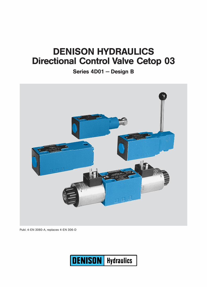
Publ. 4-EN 3060-A, replaces 4-EN 306-D
DENISON HYDRAULICSDirectional Control Valve Cetop 03
Series 4D01 − Design B

FEATURES, DESCRIPTION
2
T
A T B
(P)Example: Solenoid operation
FEATURES x Low pressure drop at high flow rates,due to optimized flow paths in body and spool
design.x Mounting configuration conform to ISO 4401.x Wide variety of spool types available, including detent.x Interchangeability of spools and bodies due to high precision manufacturing
processes.x Position control by inductive detector (see pages 12, 13).x Soft shift version available.x Low electrical power consumption (31 W / 24 VDC).x Change of solenoid coil is fast and simple without risk of oil leakage.x Pressure up to 210 bar (DC) / 140 bar (AC) allowable in the tank port.x Electrical connection by standard 3 pin connector according to ISO 4400 or DIN
43650.x All components designed and tested for a minimum life of 10 million cycles.x Every valve is factory tested prior to delivery.x Worldwide DENISON Service.
DESCRIPTION DENISON’s direct operated Directional Control Valve 4D01 conforms to Cetop 03
standard interface.
They are designed to be subplate or manifold mounted or used in conjunction with
the stack valves system (see also Bulletin 8-EN 565).
Both the valve mounting interface and electrical connection methods available
conform to the accepted International Standards Cetop, ISO and DIN.
The five annuli body design gives a precise guide for many types of spools.
High precision economical manufacturing processes allow interchangeability of
spools without the need for selective assembly.
For any applications which are not covered by the ordering code details, please
contact your local DENISON office.
OPERATION The Directional Control 4D01 consists principally of a spool, body and either one or
two actuators, depending on the application. The spool is shifted either by use of
solenoids, mechanical actuator, hydraulic or pneumatic actuator, allowing oil under
pressure from port P to flow to either port A or B, and subsequently connecting the
alternate port to the tank. De-energizing the actuator allows the spring to return the
spool to the centre or offset position. The manual override option allows for manual
operation of the spool.
ORIFICE In certain operating conditions a higher flow-volume can take place than the
functional limit of the valve permits.
In this case it is recommended to fit an orifice-plug in the P-port. For order details
refer to page 3 or 4.

ORDERING CODE − SOLENOID OPERATION
3
Model No.: 4D01 . . .. .. .. B ... .. .. .. .. ..− −− −
1 Series
01 = Cetop 03
2 Body
3 = Standard
F = only for spools 55, 56
3 Control
1 = 1 solenoid
2 = 2 solenoids
7 = 2 solenoids, 2 pos. detents
(only for spools 11, 12, 51, 52 & 91)
4 Spool Type
refer to pages 5 and 6
5 Spool Position
01 = 2 (a, b), Spring offset to pos. ”b”, energized to ”a”
02 = 2 (a, b), Spring offset to pos. ”a”, energized to ”b”
03 = 3 (a, o, b), Spring centered pos. ”o”
05 = 2 (o, b), Spring centered pos. ”o”, energized to ”b”
06 = 2 (o, a), Spring centered pos. ”o”, energized to ”a”
09 = 2 pos. detents (for control option 7)
6 End Cap
01 = for control 1
02 = for controls 2, 7
Versions with inductive detector:
SA = for control 1: neutral position controlled
SB = for control 1: ”a” or ”b” position controlled
TC = for control 2: ”a” or ”b” position controlled
SC = for control 2: ”b” or ”a” position controlled
TA = for control 2: ”o” position controlled
SA = for control 2: ”o” position controlled
k For AC & DC sol.
(see page 12)
k For DC sol. only
(see page 13)
7 Design Letter
8 Seal Class
1 = NBR-seals (Standard)
4 = EPR-seals
5 = FPM-seals (Viton`)
9 Solenoid Voltage
G0R = 12 V
G0Q = 24 V DC
G0D = 27 V
W01= 115 V / 60 Hz
W02= 230 V / 60 HzAC
W06= 115 V / 50 Hz
W07= 230 V / 50 Hzk k
Order information for plug-in connectors see pages 9 or 10
1* Valve Accessories / Modifications
08 = Orifice 0.8 mm dia. in P-port
10 = Orifice 1.0 mm dia. in P-port
12 = Orifice 1.2 mm dia. in P-port
32 = Tube cartridge without manual override
52 = Tube cartridge with manual override and rubber cover
G3 = Tube cartridge with manual override and soft shift orifice (only for DC version) − see page 11
1 2 3 4 5 6 7 8 9 0 1 2 3 4

ORDERING CODE − LEVER, CAM, PNEUMATIC & HYDRAULIC OPERATION
4
Model no.: 4D01 . . .. .. .. B .. .. .. ..− −− −
1 Series
01 = Cetop 03
2 Body
3 = Standard
F = only for spools 55, 56
3 Control
4 = Lever operated
5 = Cam operated
D = Pneumatic operation, one-side
E = Pneumatic operation, both-sides
F = Pneumatic operation, both-sides (2 pos. det.)
Q = Hydraulic operation, one-side
R = Hydraulic operation, both-sides
S = Hydraulic operation, both sides (2 pos. det.)
4 Spool Type
refer to pages 5 and 6
5 Spool Position
01 = 2 (a, b), Spring offset to pos. ”b”, activated to ”a”
02 = 2 (a, b), Spring offset to pos. ”a”, activated to ”b”
03 = 3 (a, o, b), Spring centering pos. ”o”
05 = 2 (o, b), Spring centering pos. ”o”, activated to ”b”
06 = 2 (o, a), Spring centering pos. ”o”, activated to ”a”
07 = 3 pos. detents (for control 4)
09 = 2 pos. detents (for control 4)
6 End Cap
01 = for controls D and Q
02 = for controls E, F, R and S
04 = for controls 4 and 5
05 = for control 4 and spool pos. 07 and 09
7 Design Letter
8 Seal Class
1 = NBR-seals (Standard)
4 = EPR-seals
5 = FPM-seals (Viton`)
9.. Valve Accessories / Modifications
10 = orifice 1.0 mm in P
12 = orifice 1.2 mm in P
1 2 3 4 5 6 7 8 9 0 1 2
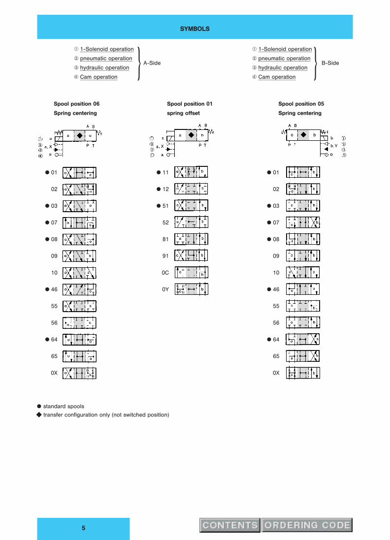
SYMBOLS
5
q 1-Solenoid operation
w pneumatic operationA-Side
e hydraulic operation
r Cam operationk
q 1-Solenoid operation
w pneumatic operationB-Side
e hydraulic operation
r Cam operationk
Spool position 06 Spool position 01 Spool position 05
Spring centering spring offset Spring centering
x 01
02
x 03
x 07
x 08
09
10
x 46
55
56
x 64
65
0X
x 11
x 12
x 51
52
81
91
0C
0Y
x 01
02
x 03
x 07
x 08
09
10
x 46
55
56
x 64
65
0X
x standard spools
y transfer configuration only (not switched position)

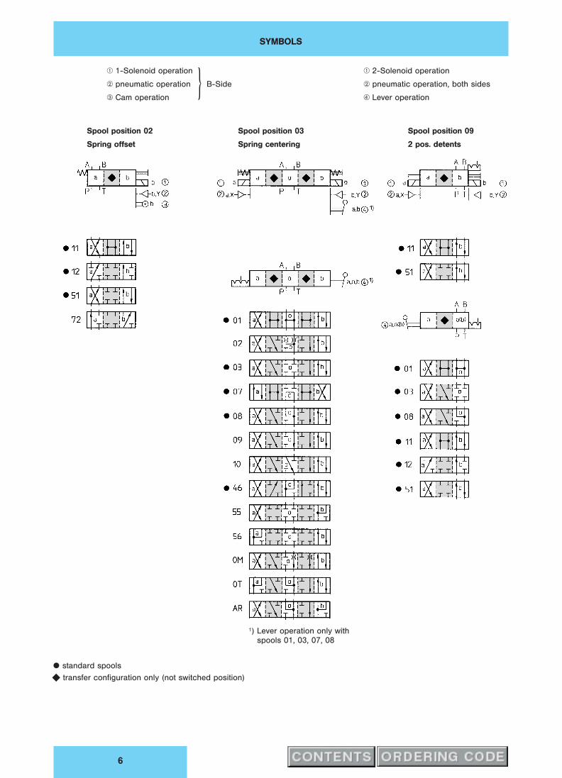
SYMBOLS
6
q 1-Solenoid operation
w pneumatic operationB-Side
e hydraulic operation
r Cam operationk
q 2-Solenoid operation
w pneumatic operation, both sides
e hydraulic operation, both sides
r Lever operation
Spool position 02 Spool position 03 Spool position 09
Spring offset Spring centering 2 pos. detents
Spool position 07
3 pos. detents
1) Lever operation not with
spools 02, 55, 56
x standard spools
y transfer configuration only (not switched position)

FUNCTIONAL LIMITS − SOLENOID OPERATION
7
FUNCTIONAL LIMITS The functional limits have been obtained with warm solenoid condition and at 10 %
undervoltage.
All flow data given is considered as 2 flow directions (e. g. PfB and simultaneously
from AfT).
For only one flow direction (4-Way-Valve used as 3-Way-Valve) the permissible flow
rates will be lower.
Valve with Standard DC-Solenoid
Flow l/min
Pre
ssure
bar
Valve with Standard AC-Solenoid
Flow l/min
Pre
ssure
bar
Spool typeCurve no. Curve no.
DC AC
01 4 2
02 9 6
03 1 2
07 5 3
08 7 2
09 10 7
10 10 7
11 2 (1) 1 (1)
12 1) 6 (8) 5 (9)
46 3 4
51 2 (1) 2 (1)
52 6 (8) 5 (9)
55 9 9
56 9 9
64 5 3
65 5 3
81 3 1
91 (1) (1)
0C 1 1
0Y 11 8
0X 11 8
( ) Curves for spool with detents
1) Only if port A or B is closed
PRESSURE DROP, CHARACTERISTICS
8
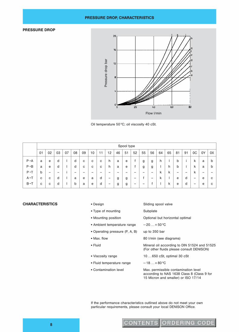
PRESSURE DROP
Flow l/min
Pre
ssure
dro
pb
ar
Oil temperature 50 hC; oil viscosity 40 cSt.
Spool type
01 02 03 07 08 09 10 11 12 46 51 52 55 56 64 65 81 91 0C 0Y 0X
PfA a e d l d c c c h a e f g g h l b i k a b
PfB a e d l d c c c h a e f g g l h b i k a b
PfT b – – i – – – – – – – – – – k k – – k – –
AfT c c d l a e a d – g g – f – k l e d – e c
BfT c c d l b a e d – g g – – f l k e d – e c
CHARACTERISTICS x Design Sliding spool valve
x Type of mounting Subplate
x Mounting position Optional but horizontal optimal
x Ambient temperature range − 20 . . . + 50 hC
x Operating pressure (P, A, B) up to 350 bar
x Max. flow 80 l/min (see diagrams)
x Fluid Mineral oil according to DIN 51524 and 51525
(For other fluids please consult DENISON)
x Viscosity range 10 . . . 650 cSt, optimal 30 cSt
x Fluid temperature range − 18 . . . + 80 hC
x Contamination level Max. permissible contamination level
according to NAS 1638 Class 8 (Class 9 for
15 Micron and smaller) or ISO 17/14
If the performance characteristics outlined above do not meet your own
particular requirements, please consult your local DENISON Office.

1- AND 2-SOLENOID OPERATED VERSIONS, DC-VOLTAGE
9
x Nominal voltage See ordering code page 3
x Power input 31 W
x Permissible pressure T . . . . 210 bar
x Solenoid response time
− sol. energized . . . 46 ms
− sol. de-energized . . . 27 ms
− quick energizing 1) . . . 30 ms 1) double voltage
x Permissible voltage difference + 5 . . . − 10 %
x max. coil temperature + 180 hC
x Temperature class H
x Relative operating period 100 %
x Type of protection IP 65
x Cycle (1/ H) . . . 16.000
x Weight 1 sol. 1.4 kg
2 sol. 1.7 kg
DC-Solenoid a DC-Solenoid b
Manual override
Coil can be turned to any position
Manual override
with rubber cover
Port function
P = Pressure
T = Tank
A + B = User
Seals for ports P, A, B, T
9.25 x 1.78 691-00012-0
36
Plug-in connectors according to ISO 4400
Versions A-Side (grey) B-Side (black)
Standard < 250 V PG 11 167-01007-8 167-01008-8
with LED (red) 15 . . . 30 V 167-01100-8 167-01101-8
with bridge rectifier 12 . . . 250 V 167-01076-8 167-01014-8
1- AND 2-SOLENOID OPERATED VERSIONS, AC-VOLTAGE
10
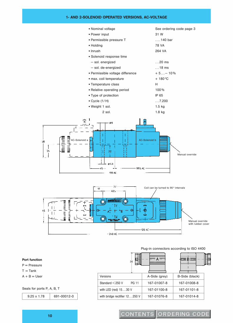
x Nominal voltage See ordering code page 3
x Power input 31 W
x Permissible pressure T . . . . 140 bar
x Holding 78 VA
x Inrush 264 VA
x Solenoid response time
− sol. energized . . . 20 ms
− sol. de-energized . . . 18 ms
x Permissible voltage difference + 5 . . . − 10 %
x max. coil temperature + 180 hC
x Temperature class H
x Relative operating period 100 %
x Type of protection IP 65
x Cycle (1/ H) . . . 7.200
x Weight 1 sol. 1.5 kg
2 sol. 1.8 kg
AC-Solenoid a AC-Solenoid b
Manual override
Coil can be turned to 90 h intervals
Manual override
with rubber cover
Port function
P = Pressure
T = Tank
A + B = User
Seals for ports P, A, B, T
9.25 x 1.78 691-00012-0
36
Plug-in connectors according to ISO 4400
Versions A-Side (grey) B-Side (black)
Standard < 250 V PG 11 167-01007-8 167-01008-8
with LED (red) 15 . . . 30 V 167-01100-8 167-01101-8
with bridge rectifier 12 . . . 250 V 167-01076-8 167-01014-8

SOFT SHIFT VERSION, OPTION G3
11
DENISON offers the Directional Control Valve in Cetop 03 size with a ”soft shift”
option (G3). A special solenoid type permits a multiple increase in the standard
solenoid response time.
The Option G3 delivers:
− Reduced pressure shocks in venting operations.
− Reduced system noise during spool transition.
− Increased lifetime of the valve and system.
Venting Venting
DC-sol. a DC-sol. b
Circuit design
300 bar
0 bar
Example sol. ”a” energized
decompression PfA (t3):
300 bar;
60 l/min;
36 cSt; 50 hC;
4D01-3203-0302-B1 G0Q-G3
Ordering code: 4D01− . . . . − . . . . − B . . . − G3
Solenoid voltage and current
G0R = 12 VDC
G0Q = 24 VDC
G0H = 48 VDC
With rectifier 1)
DC-Output AC-Input
GAN = 102 VDC 115 V / 50 (60) Hz
GAG = 205 VDC 230 V / 50 (60) Hz
GAR = 98 VDC 110 V / 50 (60) Hz
Modification
G3 = soft shift
1) For applications with AC input voltage a DC solenoid with rectifier
connector must be used!
Depending on spool type, the functional limits of the soft shift valve will be reduced
with as much as 25 % in comparison to the data in this bulletin.
Note: Ensure that the solenoid tube cartridges are filled with oil at all times. For that
the tube cartridges have venting screws (see above). In applications above the oil
level, the use of a check valve . . . 2 bar in the tank line is recommended.
Pressure shift sequence of spool stroke ofa or ofb
Pre
ssu
rep
(bar)
Time t (ms)
t1 t2
Standard versionwithout option G3
0
300
200
100
0
1
0 200 400 600 800 1000P
ressu
rep
(bar)
Time t (ms)
t3 t4
Soft shift valvewith option G3
0
300
200
100
0
1
0 200 400 600 800 1000
Response times (ms) for 24 V DC Solenoid
t1 t2 t3 t4
Spool stroke 35...40 55...60 300...500 400...800
Pressure change 20...25 35...40 80...200 80...400
Note:
Response time will be influenced by changes in viscosity, pressure or flow.
1 SOLENOID VERSION WITH POSITION CONTROL
12
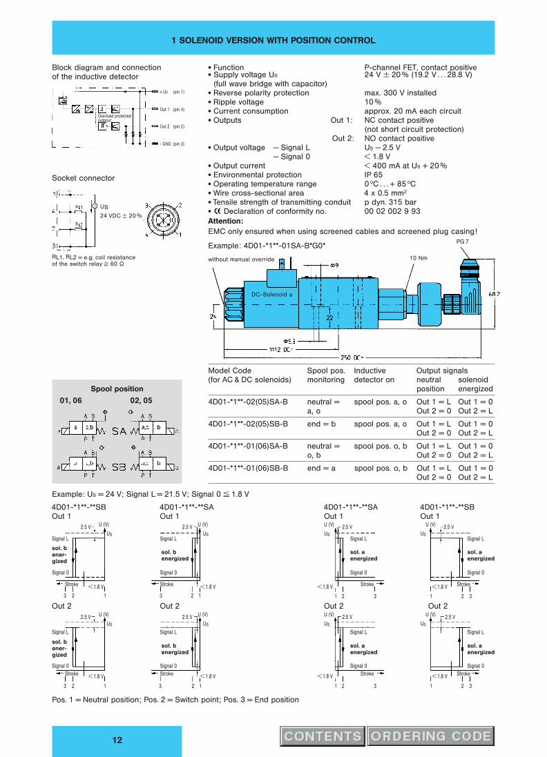
x Function P-channel FET, contact positivex Supply voltage US 24 V ± 20 % (19.2 V . . . 28.8 V)
(full wave bridge with capacitor)x Reverse polarity protection max. 300 V installedx Ripple voltage 10 %x Current consumption approx. 20 mA each circuitx Outputs Out 1: NC contact positive
(not short circuit protection)
Out 2: NO contact positivex Output voltage − Signal L US − 2.5 V
− Signal 0 < 1.8 Vx Output current < 400 mA at US + 20 %x Environmental protection IP 65x Operating temperature range 0 hC . . . + 85 hCx Wire cross-sectional area 4 x 0.5 mm2
x Tensile strength of transmitting conduit p dyn. 315 barx Declaration of conformity no. 00 02 002 9 93
Attention:
EMC only ensured when using screened cables and screened plug casing!
Spool position
01, 06 02, 05
Example: 4D01-*1**-01SA-B*G0*
without manual override
DC-Solenoid a
10 Nm
PG 7
Block diagram and connection
of the inductive detector
Overload protectedoutpout
+ US (pin 1)
Out 1 (pin 4)
Out 2 (pin 2)
– GND (pin 3)
Socket connector
US
24 VDC ± 20 %
RL1, RL2 = e.g. coil resistance
of the switch relay ≥ 60 ¸
Model Code Spool pos. Inductive Output signals
(for AC & DC solenoids) monitoring detector on neutral solenoid
position energized
4D01-*1**-02(05)SA-B neutral = spool pos. a, o Out 1 = L Out 1 = 0
a, o Out 2 = 0 Out 2 = L
4D01-*1**-02(05)SB-B end = b spool pos. a, o Out 1 = L Out 1 = 0
Out 2 = 0 Out 2 = L
4D01-*1**-01(06)SA-B neutral = spool pos. o, b Out 1 = L Out 1 = 0
o, b Out 2 = 0 Out 2 = L
4D01-*1**-01(06)SB-B end = a spool pos. o, b Out 1 = L Out 1 = 0
Out 2 = 0 Out 2 = L
Example: US = 24 V; Signal L = 21.5 V; Signal 0 ≤ 1.8 V
4D01-*1**-**SA 4D01-*1**-**SB
Out 1 Out 1U (V)
2.5 V
USSignal L
Signal 0
Stroke< 1.8 V
Out 2U (V)
2.5 V
US
Signal L
Signal 0
Stroke< 1.8 V
U (V)2.5 V
USSignal L
Signal 0
Stroke< 1.8 V
Out 2U (V)
2.5 V
US
Signal L
Signal 0
Stroke< 1.8 V
1 2 3 1 2 3
1 2 3 1 2 3
sol. a
energized
sol. a
energized
sol. a
energized
sol. a
energized
Pos. 1 = Neutral position; Pos. 2 = Switch point; Pos. 3 = End position
4D01-*1**-**SB 4D01-*1**-**SA
Out 1 Out 1U (V)
2.5 V
USSignal L
Signal 0
Stroke < 1.8 V
Out 2U (V)
2.5 V
US
Signal L
Signal 0
Stroke < 1.8 V
U (V)2.5 V
USSignal L
Signal 0
Stroke < 1.8 V
Out 2U (V)
2.5 V
US
Signal L
Signal 0
Stroke < 1.8 V
3 2 1 3 2 1
3 2 1 3 2 1
sol. b
ener-
gized
sol. b
ener-
gized
sol. b
energized
sol. b
energized

2 SOLENOID VERSION WITH POSITION CONTROL
13
x Function P-channel FET, contact positivex Supply voltage US 24 V ± 20 % (19.2 V. . . 28.8 V)
(full wave bridge with capacitor)x Reverse polarity protection max. 300 V installedx Ripple voltage 10 %x Current consumption approx. 20 mA each circuitx Outputs Out 1: NC contact positive
(not short circuit protection)
Out 2: NO contact positivex Output voltage − Signal L US − 2.5 V
− Signal 0 < 1.8 Vx Output current < 400 mA at US + 20 %x Environmental protection IP 65x Operating temperature range 0 hC . . . + 85 hCx Wire cross-sectional area 4 x 0.5 mm2
x Tensile strength of transmitting conduit p dyn. 140 barx Declaration of conformity no. 00 02 002 9 93
Attention:
EMC only ensured when using screened cables and screened plug casing!
Spool position
03
Example: 4D01-32**-03SC
without manual override
DC-Solenoid a DC-Solenoid b
10 Nm
PG 7
Block diagram and connection
of the inductive detector
Overloadprotectedoutpout
Oszilator Demo-dulator
+ US (pin 1)
Out 1 (pin 4)
Out 2 (pin 2)
– GND (pin 3)
Socket connector
US
24 VDC ± 20 %
RL1, RL2 = e.g. coil resistance
of the switch relay ≥ 60 ¸
Model Code Spool pos. Inductive Output signals
(for DC solenoids only) monitoring detector on neutral sol. b sol. a
a–o–b position energized energized
4D01-32**-03TC-B*G0* end = spool pos. a Out 1 = L Out 1 = 0 Out 1 = L
a, b Out 2 = L Out 2 = L Out 2 = 0
4D01-32**-03SC-B*G0* end = spool pos. b Out 1 = L Out 1 = L Out 1 = 0
b, a Out 2 = L Out 2 = 0 Out 2 = L
4D01-32**-03TA-B*G0* neutral = o spool pos. a Out 1 = L Out 1 = 0 Out 1 = L
Out 2 = L Out 2 = L Out 2 = 0
4D01-32**-03SA-B*G0* neutral = o spool pos. b Out 1 = L Out 1 = L Out 1 = 0
Out 2 = L Out 2 = 0 Out 2 = L
Example: US = 24 V; Signal L = 21.5 V; Signal 0 ≤ 1.8 V
Monitoring neutral Position ± Monitoring end Position ±4D01-32**-03SA 4D01-32**-03TA 4D01-32**-03SC 4D01-32**-03TC
Out 1 Out 1 Out 1 Out 1U (V)
2.5 VUS
Signal L
Signal 0
Stroke Stroke< 1.8 V
Out 2U (V)
2.5 VUS
Signal L
Signal 0
Stroke Stroke
< 1.8 V
U (V)2.5 V
USSignal L
Signal 0
Stroke Stroke
< 1.8 V
Out 2U (V)
2.5 VUS
Signal L
Signal 0
Stroke Stroke< 1.8 V
U (V)2.5 V
USSignal L
Signal 0
Stroke Stroke< 1.8 V
Out 2U (V)
2.5 VUS
Signal L
Signal 0
Stroke Stroke
< 1.8 V
U (V)2.5 V
USSignal L
Signal 0
Stroke Stroke
< 1.8 V
Out 2U (V)
2.5 VUS
Signal L
Signal 0
Stroke Stroke< 1.8 V
sol. a
energized
sol. b
energized
sol. b
energized
sol. a
energized
sol. a
energized
sol. b
energized
sol. b
energized
sol. a
energized
Pos. 1 = Neutral position; Pos. 2 = Switch point; Pos. 3 = End position

LEVER OPERATED VERSION
14
x Functional Limits 60 l/min for spools 01, 02, 03, 08, 09, 10, 46, 55, 56, 0X
(at 350 bar)40 l/min for spools 07, 64, 65
x Operating force 30 N
x Angle of operation ± 17 h
x Max. tank pressure 160 bar
x Weight 1.7 kg
Port function
P = Pressure
T = Tank
A + B = User
Seals for ports P, A, B, T
9.25 x 1.78 691-00012-0
CAM OPERATED VERSION
15
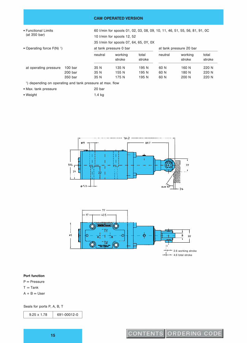
x Functional Limits 60 l/min for spools 01, 02, 03, 08, 09, 10, 11, 46, 51, 55, 56, 81, 91, 0C
(at 350 bar)10 l/min for spools 12, 52
35 l/min for spools 07, 64, 65, 0Y, 0X
x Operating force F(N) 1) at tank pressure 0 bar at tank pressure 20 bar
neutral working total neutral working total
stroke stroke stroke stroke
at operating pressure 100 bar 35 N 135 N 195 N 60 N 160 N 220 N
200 bar 35 N 155 N 195 N 60 N 180 N 220 N
350 bar 35 N 175 N 195 N 60 N 200 N 220 N
1) depending on operating and tank pressure at max. flow
x Max. tank pressure 20 bar
x Weight 1.4 kg
2.6 working stroke
4.6 total stroke
Port function
P = Pressure
T = Tank
A + B = User
Seals for ports P, A, B, T
9.25 x 1.78 691-00012-0
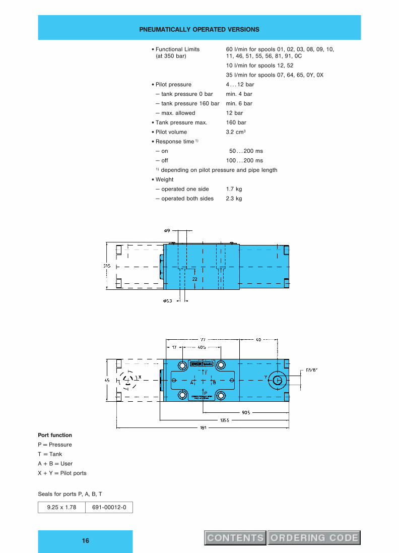
PNEUMATICALLY OPERATED VERSIONS
16
x Functional Limits 60 l/min for spools 01, 02, 03, 08, 09, 10,
(at 350 bar) 11, 46, 51, 55, 56, 81, 91, 0C
10 l/min for spools 12, 52
35 l/min for spools 07, 64, 65, 0Y, 0X
x Pilot pressure 4 . . . 12 bar
− tank pressure 0 bar min. 4 bar
− tank pressure 160 bar min. 6 bar
− max. allowed 12 bar
x Tank pressure max. 160 bar
x Pilot volume 3.2 cm3
x Response time 1)
− on 50 . . . 200 ms
− off 100 . . . 200 ms
1) depending on pilot pressure and pipe length
x Weight
− operated one side 1.7 kg
− operated both sides 2.3 kg
Port function
P = Pressure
T = Tank
A + B = User
X + Y = Pilot ports
Seals for ports P, A, B, T
9.25 x 1.78 691-00012-0

HYDRAULICALLY OPERATED VERSION
17
x Functional Limits 60 l/min for spools 01, 02, 03, 08, 09, 10,
(at 350 bar) 11, 46, 51, 55, 56, 81, 91, 0C
10 l/min for spools 12, 52
35 l/min for spools 07, 64, 65, 0Y, 0X
x Max. tank pressure 160 bar
x Pilot pressure min. 10 bar > tank pressure
max. 210 bar
x Pilot volume (each side) 1 cm3
x Response time 1) pp 50 bar pp 200 bar
− on 50 . . . 100 ms 15 . . . 40 ms
− off 60 . . . 160 ms 60 . . . 160 ms
1) depending on pilot pressure and pipe length
x Weight
− operated one side 1.6 kg
− operated both sides 2.2 kg
Port function
P = Pressure
T = Tank
A + B = User
X + Y = Pilot ports
Seals for ports P, A, B, T
9.25 x 1.78 691-00012-0
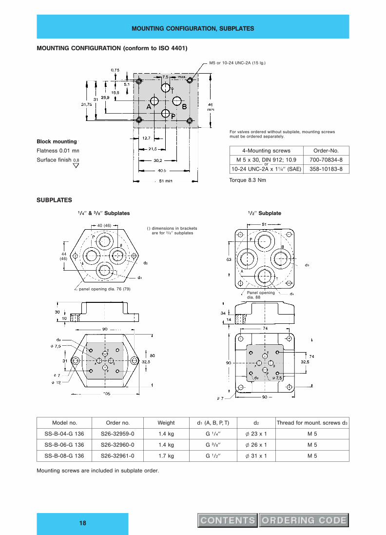
MOUNTING CONFIGURATION, SUBPLATES
18
MOUNTING CONFIGURATION (conform to ISO 4401)
Block mounting face
Flatness 0.01 mm / 100 mm length
Surface finish 0,8
B
For valves ordered without subplate, mounting screws
must be ordered separately.
4-Mounting screws Order-No.
M 5 x 30, DIN 912; 10.9 700-70834-8
10-24 UNC-2A x 11⁄4HH (SAE) 358-10183-8or
Torque 8.3 Nm
SUBPLATES
Model no. Order no. Weight d1 (A, B, P, T) d2 Thread for mount. screws d3
SS-B-04-G 136 S26-32959-0 1.4 kg G 1/4HH l 23 x 1 M 5
SS-B-06-G 136 S26-32960-0 1.4 kg G 3/8HH l 26 x 1 M 5
SS-B-08-G 136 S26-32961-0 1.7 kg G 1/2HH l 31 x 1 M 5
Mounting screws are included in subplate order.
M5 or 10-24 UNC-2A (15 lg.)
1/4HH & 3/8HH Subplates
panel opening dia. 76 (79)
40 (46)
44
(46)
( ) dimensions in brackets
are for 3/8HH subplates
1/2HH Subplate
Panel opening
dia. 88

Publ. 4-EN 3300-A, replaces 4-EN 330-D and 4-EN 320-B
DENISON HYDRAULICSDirectional Control Valve Cetop 05
Series 4D02 − Design B

FEATURES, DESCRIPTION
2
Example: Solenoid operation
FEATURES x Low pressure drop at high flow rates,due to optimized flow paths in body and spool
design. 5-chamber technology.x Mounting configuration conform to ISO 4401.x Wide variety of spool types available, including detent.x Interchangeability of spools and bodies due to high precision manufacturing
processes.x Soft Shift version (Code G3).x Change of solenoid coil is fast and simple without any risk of oil leakage.x Solenoid coil can be turned to any position.x Pressure up to 210 bar allowable on tank port as standard.x Electrical connection by standard 3 pin plug confirming to ISO 4400
or DIN 43650.x All components designed and tested for a minimum life of 10 million cycles.x Every valve is factory tested prior to delivery.x Worldwide DENISON Service.
DESCRIPTION DENISON’s direct operated Directional Control Valve 4D02 conforms to Cetop 5
standard interface.
It is designed to be subplate or manifold mounted and to be used in conjunction with
the stack valve system (see also publication 8-EN 575).
Both the valve mounting interface and electrical connection methods available
conform to the accepted International Standards Cetop, ISO and DIN.
The five annuli body design gives a precise guide for the spool throughout it’s stroke.
For any application not covered by the ordering code details, please contact your
local DENISON office.
OPERATION The Directional Control 4D02 consists principally of a spool, body, and either one or
two actuators, depending on the application. The spool is shifted either by use of
solenoids, mechanical or pneumatic actuator, allowing oil under pressure to flow
from Port P to either port A or Port B and subsequently connecting the alternate port
to tank.
De-energizing the actuator allows the spring to return the spool to the centre or
offset position. The manual override pin(s) at the end of the solenoid tubes allows
manual operation of the spool.
ORIFICE In certain operating conditions a higher flow can take place than the functional limit
of the valve permits.
In order to limit the flow through the valve it is recommended to fit an orifice-plug in
the P-port.
For order details refer to page 3 or 4.
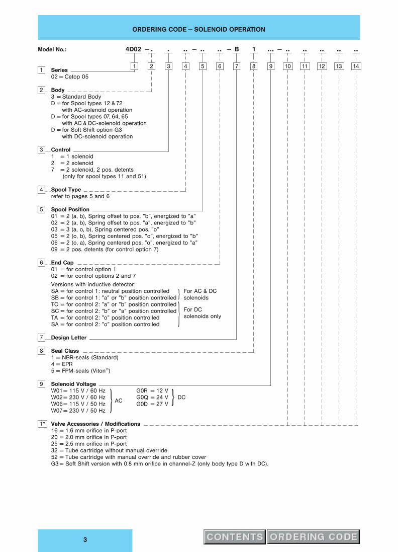
ORDERING CODE − SOLENOID OPERATION
3
Model No.: 4D02 . . .. .. .. B ... .. .. .. .. ..− −− −
1 Series
02 = Cetop 05
2 Body
3 = Standard Body
D = for Spool types 12 & 72
with AC-solenoid operation
D = for Spool types 07, 64, 65
with AC & DC-solenoid operation
D = for Soft Shift option G3
with DC-solenoid operation
3 Control
1 = 1 solenoid
2 = 2 solenoid
7 = 2 solenoid, 2 pos. detents
(only for spool types 11 and 51)
4 Spool Type
refer to pages 5 and 6
5 Spool Position
01 = 2 (a, b), Spring offset to pos. ”b”, energized to ”a”
02 = 2 (a, b), Spring offset to pos. ”a”, energized to ”b”
03 = 3 (a, o, b), Spring centered pos. ”o”
05 = 2 (o, b), Spring centered pos. ”o”, energized to ”b”
06 = 2 (o, a), Spring centered pos. ”o”, energized to ”a”
09 = 2 pos. detents (for control option 7)
6 End Cap
01 = for control option 1
02 = for control options 2 and 7
Versions with inductive detector:
SA = for control 1: neutral position controlled
SB = for control 1: ”a” or ”b” position controlled
TC = for control 2: ”a” or ”b” position controlled
SC = for control 2: ”b” or ”a” position controlled
TA = for control 2: ”o” position controlled
SA = for control 2: ”o” position controlled
k For AC & DC
solenoids
k For DC
solenoids only
7 Design Letter
8 Seal Class
1 = NBR-seals (Standard)
4 = EPR
5 = FPM-seals (Viton`)
9 Solenoid Voltage
G0R = 12 V
G0Q = 24 V DC
G0D = 27 V
W01= 115 V / 60 Hz
W02= 230 V / 60 HzAC
W06= 115 V / 50 Hz
W07= 230 V / 50 Hzk k
1* Valve Accessories / Modifications
16 = 1.6 mm orifice in P-port
20 = 2.0 mm orifice in P-port
25 = 2.5 mm orifice in P-port
32 = Tube cartridge without manual override
52 = Tube cartridge with manual override and rubber cover
G3 = Soft Shift version with 0.8 mm orifice in channel-Z (only body type D with DC).
1 2 3 4 5 6 7 8 9 0 1 2 3 4

ORDERING CODE − LEVER, CAM, PNEUMATIC OPERATION
4
Model no.: 4D02 . . .. .. .. B .. .. .. ..− −− −
1 Series
02 = Cetop 05
2 Body
3 = Standard
D = only for spools types 07, 64, 65
3 Control
4 = Lever operated
5 = Cam operated
D = Pneumatic operation, one-side
E = Pneumatic operation, both-sides
F = Pneumatic operation, both-sides (2 pos. det.)
4 Spool Type
refer to pages 5 and 6
5 Spool Position
01 = 2 (a, b), Spring offset to pos. ”b”, activated to ”a”
02 = 2 (a, b), Spring offset to pos. ”a”, activated to ”b”
03 = 3 (a, o, b), Spring centering pos. ”o”
05 = 2 (o, b), Spring centering pos. ”o”, activated to ”b”
06 = 2 (o, a), Spring centering pos. ”o”, activated to ”a”
07 = 3 pos. detents (for control 4)
09 = 2 pos. detents (for control 4)
6 End Cap
01 = for controls D
02 = for controls E, F
04 = for controls 4 and 5
05 = for control 4 and spool pos. 07 and 09
7 Design Letter
8 Seal Class
1 = NBR-seals (Standard)
4 = EPR
5 = FPM-seals (Viton`)
9.. Valve Accessories / Modifications
20 = 2.0 mm orifice in P-port
25 = 2.5 mm orifice in P-port
1 2 3 4 5 6 7 8 9 0 1 2

SYMBOLS
5
q 1-Solenoid operation
w pneumatic operation A-Side
e Cam operationk q 1-Solenoid operation
w pneumatic operation B-Side
e Cam operationk
Spool position 06 Spool position 01 Spool position 05
Spring centering Spring offset Spring centering
x standard spools
y transfer configuration only (not switched position)
SYMBOLS
6
q 1-Solenoid operation
w pneumatic operation B-Side
e Cam operationk q 2-Solenoid operation
w pneumatic operation, both sides
r Lever operation
Spool position 02
Spring offset
Spool position 03
Spring centering
Spool position 09
2 pos. detents
x standard spools
y transfer configuration only (not switched position)
1) Lever operation only with
spools 01, 03, 07, 08

PRESSURE DROP
7
PRESSURE DROP
Flow Q / l/min
Pre
ssure
Dro
p„
p/
bar
All performance data is recorded with port TA connected to tank. Additionally
connecting also TB to tank, pressure drop can be reduced by 1.5 . . . 3 bar.
Oil temperature 50 hC (122 hF); oil viscosity 40 cSt.
Spool Type Flow Direction o-Position b-Pos. a-Pos.
P−A P−B A−T B−T P−T P−A P−B A−T B−T P−A P−B
01 1 1 4 10 14
02 3 3 4 7 19 19
03 3 3 5 8
07 12 12 7 13 13
08 3 3 3 6 17 18
09 3 3 4 6 17
10 3 3 3 9 16
11 5 5 9 11
12 4 4
46 1 1 5 9
51 5 5 10 11
55 9 6 6 12
56 7 7 12 13
72 4 6
0M 3 3 4 7
0T 6 11 9 15 13 13
AR 12 5 10 15 11 11

CHARACTERISTICS, FUNCTIONAL LIMITS
8
CHARACTERISTICS x Design Sliding spool valve
x Type of mounting Subplate
x Mounting position Optional but horizontal optimal
x Ambient temperature range − 20 . . . + 50 hC
x Operating pressure (P, A, B) up to 315 bar (350 bar on request)
x Permissible tank pressure (T) up to 210 bar (DC solenoids)
up to 140 bar (AC solenoids)
x Max. flow 140 l/min see diagrams
x Fluid Mineral oil according to DIN 51524 and 51525
(For other fluids please consult DENISON)
x Viscosity range 10 . . . 650 cSt, optimal 30 cSt
x Fluid temperature range − 18 . . . + 80 hC
x Contamination level Max. permissible contamination level
confirming to NAS 1638 Class 8 (Class 9 for
15 Micron and smaller) or ISO 17/14
FUNCTIONAL LIMITS The functional limits have been obtained with warm solenoid condition and at 10 %
undervoltage from the selected nominal value.
All flow data given is considered for 2 flow directions (e. g. PfB and simultaneously
from AfT).
For single flow direction (4-Way-Valve used as 3-Way-Valve) the permissible flow
rates will be reduced by as much as 25 . . . 30 % in comparison to the data below.
03/08/0M/0T/ARValve with DC Solenoid(s)
Valve with AC Solenoid(s)
Valve with DC Solenoid(s)
Valve with AC Solenoid(s)
Q / l/min
Q / l/min
Q / l/min
Q / l/min
/5 detent
/5 detent
p/
bar
p/
bar
p/
bar
p/
bar
If the performance characteristics outlined above do not meet your
requirements, please consult your local DENISON Office.

1- AND 2-SOLENOID DC OPERATED VERSIONS
9
x Nominal voltage See ordering code on page 3
x Power input 48 W
x Solenoid response time
− sol. energized . . . 58 ms
− sol. de-energized . . . 39 ms
x Permissible voltage difference + 5 % . . . − 10 %
x Max. coil temperature + 180 hC
x Temperature class H
x Relative operating period 100 %
x Type of protection IP 65
x Cycle (1/H) . . . 13.000
x Weight (1 solenoid version) 5.2 kg
(2 solenoid version) 6.6 kg
Manual override
DC Solenoid a DC Solenoid b
Coil can be turned to any position
Manual
override
with rubber
cover
Port function
P = Pressure
T = Tank
A & B = User
Seals for ports P, T, A, B
12.42 x 1.78 691-00014-0

1- AND 2-SOLENOID AC OPERATED VERSIONS
10
x Nominal voltage See ordering code on page 3
x Power input 43 W
x Holding (115 V / 60 Hz) 102 VA
x Inrush (115 V / 60 Hz) 518 VA
x Solenoid response time
− sol. energized . . . 25 ms
− sol. de-energized . . . 18 ms
x Permissible voltage difference + 5 % . . . − 10 %
x Max. coil temperature + 180 hC
x Temperature class H
x Relative operating period 100 %
x Type of protection IP 65
x Cycle (1/H) . . . 6.500
x Weight (1 solenoid version) 4.4 kg
(2 solenoid version) 5.2 kg
Venting
AC
Solenoid b
AC
Solenoid a
AC
Solenoid b
Manual
override
Manual override
with rubber cover
Version with Venting
(for spool types 07, 12, 64, 65, 72)
See page 11 for venting description
Port function
P = Pressure
T = Tank
A & B = User
Seals for ports P, T, A, B
12.42 x 1.78 691-00014-0

SOFT SHIFT VERSION, OPTION CODE G3
11
GENERAL DENISON offers this Directional Control Valve in CETOP 05 size with a ”Soft Shift”
option (G3). An orifice fitted in channel Z permits an increase in the standard spool
response time (for body type D with DC only).
The Option G3 delivers:
− Reduced pressure shocks in venting operations.
− Reduced system noise during spool transition.
− Increased lifetime of the valve and system.
Orifice-plug 0.8 mm dia.
036–64596–0
Pos. 1
Pos. 2
Pos. 3
DC Solenoid a DC Solenoid b
FUNCTIONAL LIMIT With body option ”D” and ”Soft Shift”, the flow rating of the valve is reduced by
approximately 25 % of the nominal value.
VENTING Ensure that channel Z is filled with oil at all times (as delivered, the channel is
prefilled with oil).
Trouble-free operation of the valve can only be ensured when it is properly vented
during the initial installation, and in case of service.
To vent this valve, please use the following procedure:
1. Remove the vent port screws pos. 1 . . . 3.
2. Fill one of the vent ports with hydraulic fluid until this runs bubble free from the
other vent ports.
3. Replace the vent port screws.

1 SOLENOID VERSION WITH POSITION CONTROL
12
x Function P-channel FET, contact positivex Supply voltage US 24 V ± 20 % (19.2 V . . . 28.8 V)
(full wave bridge with capacitor)x Reverse polarity protection max. 300 V installedx Ripple voltage 10 %x Current consumption approx. 20 mA each circuitx Outputs Out 1: NC contact positive
(not short circuit protection)
Out 2: NO contact positivex Output voltage − Signal L US − 2.5 V
− Signal 0 < 1.8 Vx Output current < 400 mA at US + 20 %x Environmental protection IP 65x Operating temperature range 0 hC . . . + 85 hCx Wire cross-sectional area 4 x 0.5 mm2
x Tensile strength of transmitting conduit p dyn. 315 barx Declaration of conformity no. 00 02 002 9 93
Attention:
EMC only ensured when using screened cables and screened plug casing!
Spool position
01, 06 02, 05
Example: 4D02-*1**-03SA
without manual
override
DC = Solenoid a
Block diagram and connection
of the inductive detector
Overload protectedoutpout
+ US (pin 1)
Out 1 (pin 4)
Out 2 (pin 2)
– GND (pin 3)
Socket connector
US
24 VDC ± 20 %
RL1, RL2 = e.g. coil resistance
of the switch relay ≥ 60 ¸
Model Code Spool pos. Inductive Output signals
(for AC & DC solenoids) monitoring detector on neutral solenoid
position energized
4D02-*1**-02(05)SA-B neutral = spool pos. a, o Out 1 = L Out 1 = 0
a, o Out 2 = 0 Out 2 = L
4D02-*1**-02(05)SB-B end = b spool pos. a, o Out 1 = L Out 1 = 0
Out 2 = 0 Out 2 = L
4D02-*1**-01(06)SA-B neutral = spool pos. o, b Out 1 = L Out 1 = 0
o, b Out 2 = 0 Out 2 = L
4D02-*1**-01(06)SB-B end = a spool pos. o, b Out 1 = L Out 1 = 0
Out 2 = 0 Out 2 = L
Example: US = 24 V; Signal L = 21.5 V; Signal 0 ≤ 1.8 V
4D02-*1**-**SA 4D02-*1**-**SB
Out 1 Out 1U (V)
2.5 V
USSignal L
Signal 0
Stroke< 1.8 V
Out 2U (V)
2.5 V
US
Signal L
Signal 0
Stroke< 1.8 V
U (V)2.5 V
USSignal L
Signal 0
Stroke< 1.8 V
Out 2U (V)
2.5 V
US
Signal L
Signal 0
Stroke< 1.8 V
1 2 3 1 2 3
1 2 3 1 2 3
sol. a
energized
sol. a
energized
sol. a
energized
sol. a
energized
Pos. 1 = Neutral position; Pos. 2 = Switch point; Pos. 3 = End position
4D02-*1**-**SB 4D02-*1**-**SA
Out 1 Out 1U (V)
2.5 V
USSignal L
Signal 0
Stroke < 1.8 V
Out 2U (V)
2.5 V
US
Signal L
Signal 0
Stroke < 1.8 V
U (V)2.5 V
USSignal L
Signal 0
Stroke < 1.8 V
Out 2U (V)
2.5 V
US
Signal L
Signal 0
Stroke < 1.8 V
3 2 1 3 2 1
3 2 1 3 2 1
sol. b
ener-
gized
sol. b
ener-
gized
sol. b
energized
sol. b
energized

2 SOLENOID VERSION WITH POSITION CONTROL
13
x Function P-channel FET, contact positivex Supply voltage US 24 V ± 20 % (19.2 V. . . 28.8 V)
(full wave bridge with capacitor)x Reverse polarity protection max. 300 V installedx Ripple voltage 10 %x Current consumption approx. 20 mA each circuitx Outputs Out 1: NC contact positive
(not short circuit protection)
Out 2: NO contact positivex Output voltage − Signal L US − 2.5 V
− Signal 0 < 1.8 Vx Output current < 400 mA at US + 20 %x Environmental protection IP 65x Operating temperature range 0 hC . . . + 85 hCx Wire cross-sectional area 4 x 0.5 mm2
x Tensile strength of transmitting conduit p dyn. 140 barx Declaration of conformity no. 00 02 002 9 93
Attention:
EMC only ensured when using screened cables and screened plug casing!
Spool position
03
Example: 4D02-32**-03SC
without manual
override
DC = Solenoid aDC = Solenoid b
Block diagram and connection
of the inductive detector
Overloadprotectedoutpout
Oszilator Demo-dulator
+ US (pin 1)
Out 1 (pin 4)
Out 2 (pin 2)
– GND (pin 3)
Socket connector
US
24 VDC ± 20 %
RL1, RL2 = e.g. coil resistance
of the switch relay ≥ 60 ¸
Model Code Spool pos. Inductive Output signals
(for DC solenoids only) monitoring detector on neutral sol. b sol. a
a-o-b position energized energized
4D02-32**-03TC-B*G0* end = spool pos. a Out 1 = L Out 1 = 0 Out 1 = L
a, b Out 2 = L Out 2 = L Out 2 = 0
4D02-32**-03SC-B*G0* end = spool pos. b Out 1 = L Out 1 = L Out 1 = 0
b, a Out 2 = L Out 2 = 0 Out 2 = L
4D02-32**-03TA-B*G0* neutral = o spool pos. a Out 1 = L Out 1 = 0 Out 1 = L
Out 2 = L Out 2 = L Out 2 = 0
4D02-32**-03SA-B*G0* neutral = o spool pos. b Out 1 = L Out 1 = L Out 1 = 0
Out 2 = L Out 2 = 0 Out 2 = L
Example: US = 24 V; Signal L = 21.5 V; Signal 0 ≤ 1.8 V
Monitoring neutral Position ± Monitoring end Position ±4D02-32**-03SA 4D02-32**-03TA 4D02-32**-03SC 4D02-32**-03TC
Out 1 Out 1 Out 1 Out 1U (V)
2.5 VUS
Signal L
Signal 0
Stroke Stroke< 1.8 V
Out 2U (V)
2.5 VUS
Signal L
Signal 0
Stroke Stroke
< 1.8 V
U (V)2.5 V
USSignal L
Signal 0
Stroke Stroke
< 1.8 V
Out 2U (V)
2.5 VUS
Signal L
Signal 0
Stroke Stroke< 1.8 V
U (V)2.5 V
USSignal L
Signal 0
Stroke Stroke< 1.8 V
Out 2U (V)
2.5 VUS
Signal L
Signal 0
Stroke Stroke
< 1.8 V
U (V)2.5 V
USSignal L
Signal 0
Stroke Stroke
< 1.8 V
Out 2U (V)
2.5 VUS
Signal L
Signal 0
Stroke Stroke< 1.8 V
sol. a
energized
sol. b
energized
sol. b
energized
sol. a
energized
sol. a
energized
sol. b
energized
sol. b
energized
sol. a
energized
Pos. 1 = Neutral position; Pos. 2 = Switch point; Pos. 3 = End position

LEVER OPERATED VERSION
14
x Functional limits 120 l/min for spools 01, 03, 08
(at 315 bar)100 l/min for spools 07, 11, 51
60 l/min for spool 12
x Max. tank pressure 160 bar
x Operating force 30 N
x Weight 5.2 kg
for detent version only
Port function
P = Pressure
T = Tank
A & B = User
Seals for ports P, T, A, B
12.42 x 1.78 691-00014-0
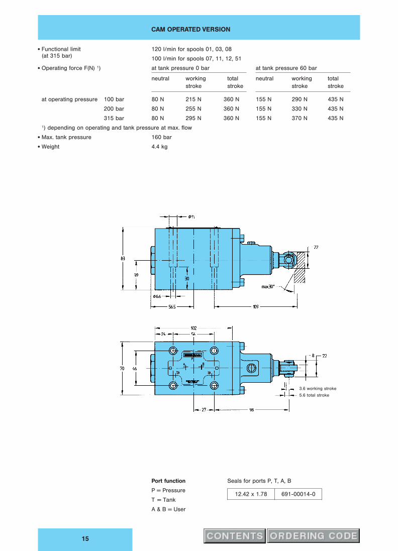
CAM OPERATED VERSION
15
x Functional limit 120 l/min for spools 01, 03, 08
(at 315 bar)100 l/min for spools 07, 11, 12, 51
x Operating force F(N) 1) at tank pressure 0 bar at tank pressure 60 bar
neutral working total neutral working total
stroke stroke stroke stroke
at operating pressure 100 bar 80 N 215 N 360 N 155 N 290 N 435 N
200 bar 80 N 255 N 360 N 155 N 330 N 435 N
315 bar 80 N 295 N 360 N 155 N 370 N 435 N
1) depending on operating and tank pressure at max. flow
x Max. tank pressure 160 bar
x Weight 4.4 kg
3.6 working stroke
5.6 total stroke
Port function
P = Pressure
T = Tank
A & B = User
Seals for ports P, T, A, B
12.42 x 1.78 691-00014-0

PNEUMATICALLY OPERATED VERSION
16
x Functional limit 140 l/min for spool 46
(at 315 bar)100 l/min for spools 01, 02, 09, 10, 11, 51
80 l/min for spools 03, 08, 0M, 0T, AR
60 l/min for spools 07, 55, 56, 72
30 l/min for spool 12
Note: See curves on page 8 for functional limits below 315 bar
x Pilot pressure 4 . . . 12 bar
− tank pressure 0 bar min. 4 bar
− tank pressure 160 bar min. 6 bar
− max. allowed 12 bar
x Tank pressure max. 160 bar
x Pilot volume 8.1 cm3
x Response time 1)
− on 80 . . . 200 ms
− off 120 . . . 200 ms
1) depending on pilot pressure and pipe length
x Weight
− operated one side 5.3 kg
− operated both sides 7.0 kg
Port function
P = Pressure
T = Tank
A & B = User
X & Y = Pilot ports
Seals for ports P, T, A, B
12.42 x 1.78 691-00014-0

SUBPLATE & MOUNTING CONFIGURATION
17
Mounting configuration conform to ISO 4401
Subplate Mounting Configuration
( ) dimensions in brackets
are for 3/4HH subplateM6 or 1/4HH-20 UNC (13 lg.)
All performance data
is recorded with port TA
connected to tank.
Additionally connecting
also TB to tank, pressure
drop can be reduced by
1.5 . . . 3 bar.
Panel opening dia. 108dia. 31 x 1
(dia. 33 x 1.5)
dia. 11
dia. 18 dia. 11
Model-No. Order-No. d1 (A, B, P, T) Weight
SS-B-08-G 138 S26-34192-0 G 1/2HH 3 kg
SS-B-12-G 138 S26-34193-0 G 3/4HH 3 kg
Please note:
Mounting screws are included in subplate order.
Block mounting face
Flatness 0.001 mm / 100 mm length
Surface finish 0.8
B
For valves ordered without subplate, mounting
screws must be ordered separately.
4 mounting screws Order-No.
M 6 x 40, DIN 912; 12.9 361-08244-8
1/4HH-20 UNC x 11/2HH (SAE) 358-12200-0
or
Torque 15 Nm

ACCESSORIES
18
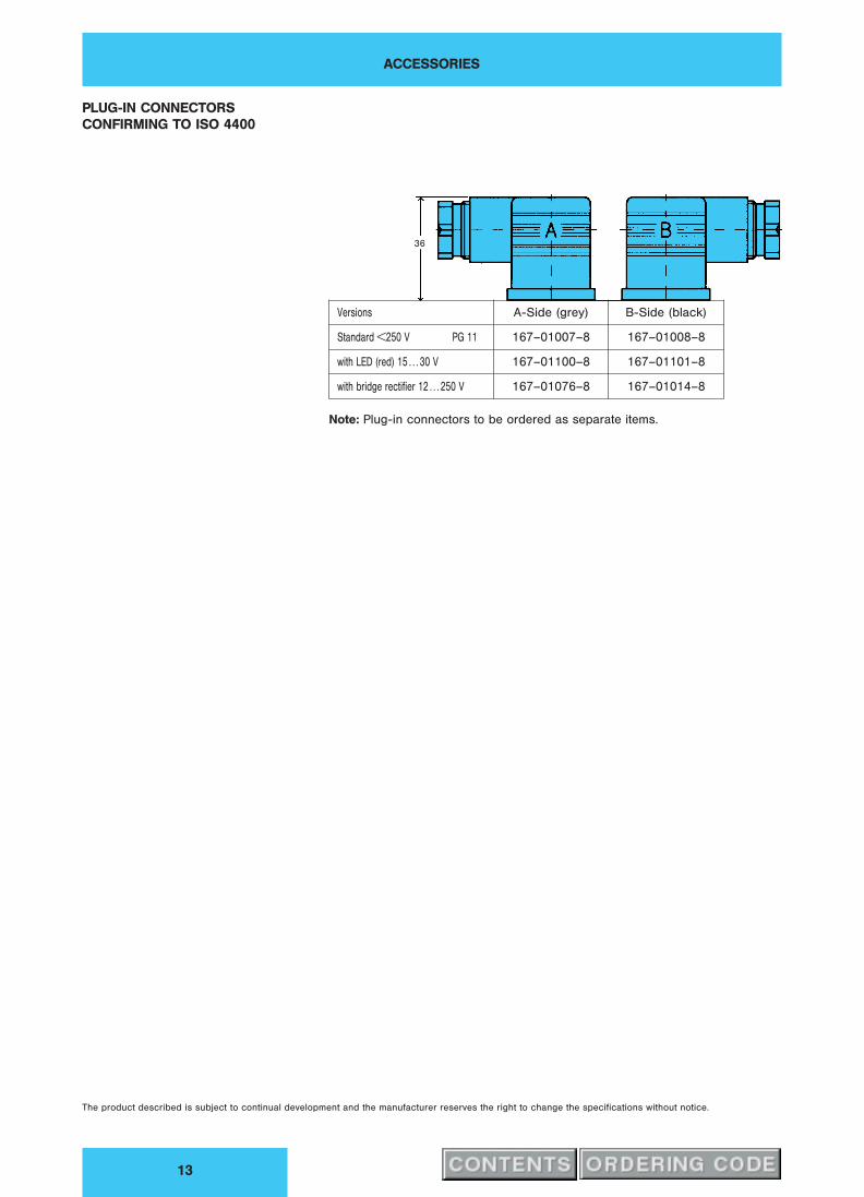
PLUG-IN CONNECTORS
CONFIRMING TO ISO 4400
36
Versions A-Side (grey) B-Side (black)
Standard <250 V PG 11 167-01007-8 167-01008-8
with LED (red) 15 . . . 30 V 167-01100-8 167-01101-8
with bridge rectifier 12 . . . 250 V 167-01076-8 167-01014-8

Publ. 4–EN 3510–A, replaces 4–EN 351–A
DENISON HYDRAULICSDirectional Control Valves
Series 4D03 – Cetop 07

FEATURES, SYMBOL, GENERAL
2
Example: DC-solenoid operation
Solenoid b Solenoid a
FEATURES x Directional control valve solenoid or hydraulically controlled.x Extremely low pressure drop – energy saving.x High functional limit up to 300 l/min at nominal pressure.x Nominal operating pressure 350 bar.x Wide variety of spool types available.x Permissible pressure in the tank port up to 350 bar with external drain, up to
210 bar with internal drain (see characteristics).x Coils are easily replaced without any oil leakage.x Interchangeability of spools and bodies due to high precision manufacturing
processes.x Mounting configuration conform to ISO 4401.x Every valve is factory tested prior to delivery.x Worldwide DENISON Service.
SYMBOL
GENERAL The DENISON 4D03 is a pilot operated directional control valve controlled by
solenoids or hydraulic pressure.
The 4D03 valve controls the flow direction in a hydraulic circuit. It delivers the
performance demanded of modern hydraulic systems. Streamlined internal
channels ensure minimum pressure drop at maximum flow.
Subplate or manifold mount as standard.

OPERATION, PILOT VALVE ORIFICE, CHARACTERISTICS
3
OPERATION The electrically operated 4-way valve 4D03 consists of a main body and a solenoid
operated pilot valve. The energized solenoid shifts the pilot control spool, thus
directing fluid to one end of the main spool, and moving it to the desired position.
Fluid can then flow e.g. from port P to either port A or B whilst the alternate port (B or
A) is connected to the tank line. The necessary pilot pressure can be obtained
internally from the system port P or from an external pressure supply connected to
port X.
De-energizing the solenoid allows both the pilot control and the main spool to return
to their neutral positions.
The hydraulically operated version may be remotely controlled by an external pilot
valve.
PILOT VALVE ORIFICE In certain operating conditions, a flow greater than the functional limit of the pilot
valve may be generated. In this case, it is recommended that one orifice be fitted in
the Pport of the pilot valve (code 10 for solenoid operation) or two orifices in the A&B
ports of the pilot cap (code P 3 for hydraulic operation).
CHARACTERISTICS x Design Sliding spool valve
x Type of mounting Subplate according to CETOP 07,
ISO 4401
x Mounting position Optional
x Ambient temperature range – 20 . . . + 50 hC
x Operating pressure (A, B, P, X) up to 350 bar
x External pilot pressure
(at 300 l/min)
– min 8.5 bar for spools with open center position
9.5 bar for spools with closed center position
–max 250 bar
> 250 bar . . . 350 bar a pilot orifice dia. .0 mm
in P-port is recommended (code 10 or P3)
x Max. flow 300 l/min (see diagrams)
x Max. leakage 300 . . . 650 ml/min (depends on spool type)
x Fluid Mineral oil according to DIN 51524 and 51525
(For other fluids please consult DENISON)
x Viscosity range 10 . . . 650 cSt, optimum 30 cSt
x Fluid temperature range – 18 . . . + 80 hC
x Contamination level Max. permissible contamination level
according to NAS 1638 Class 8 (Class 9 for
15 Micron and smaller) or ISO 17/14

ORDERING CODE
4
Model No.: 4D03 . .. .. . . A ... .. .. ..– 3 – 03 – –
1 Series
03 = Cetop 07
2 Control
A = Pilot operated, 1 solenoid (4D01)
B = Pilot operated, 2 solenoids (4D01)
C = Pilot operated, 2 solenoids (4D01)
pilot valve: 2 pos. detents
0 = Hydraulic operation
3 Spool Type
refer to pages 5 and 6
4 Spool Position
01 = 2 (a, b ), Spring offset to pos. ”b”, energized to ”a”
02 = 2 (a, b ), Spring offset to pos. ”a”, energized to ”b”
03 = 3 (a, o, b), Spring centered pos. ”o”
04 = 2 (a, b), Spool is not centered, energized to ”a” or ”b”
(pilot valve with detents)
05 = 2 (o, b), Spring centered pos. ”o”, energized to ”b”
06 = 2 (o, a), Spring centered pos. ”o”, energized to ”a”
5 Pilot Connection
0 = External PP, external PD (for control code)
1 = Internal PP, internal PD 1)
2 = Internal PP, external PD 1)
3 = External PP, internal PD
4 = External PP, external PD
6 Main Valve Accessories
0 = without
1 = Shifting time adjustment (meter-in control)
2 = Shifting time adjustment (meter-out control)
6 = Shifting time adjustment (meter-in control) & integral check in ”P” 1)
8 = Shifting time adjustment (meter-out control) & integral check in ”P” 1)
4 = Integral check in ”P” 1)
7 Design Letter
8 Seal Class
1 = NBR-seals (Standard)
4 = EPR-seals
5 = FPM-seals (Viton`)
9 Solenoid Voltage
G0R = 12 V
G0Q = 24 V DC
G0D = 27 V
W01 = 115 V / 60 Hz
W02 = 230 V / 60 HzAC
W06 = 115 V / 50 Hz
W07 = 230 V / 50 Hzk k
Order information for plug-in connectors see page 13
1* Pilot Accessories / Modifications
10 = 1.0 mm orifice in P-port; for solenoid with manual override
1032 = 1.0 mm orifice in P-port; for solenoid without manual override
1052 = 1.0 mm orifice in P-port; for solenoid with manual override; with rubber cover
P3 = 1.0 mm orifices in A & B-ports of the cap; for hydraulic operation only (control code 0)
1) Note:
For valves with no-load flow (spools 0, 07) and internal PP an integral check is recommended in P-port of the main
body to obtain the minimum pilot pressure. The integral check is not provided for load pressure holding back to P-port.
1 2 3 4 5 6 7 8 9 0 1 2

SPOOL TYPES, PRESSURE DROP, FUNCTIONAL LIMITS
5
Spool Types
Pressure Drop
Spool Type 01 Spool Type 07 Spool Type 10 Spool Type 46
Spool Type 02 Spool Type 08 Spool Type 13 Spool Type 55
Spool Type 03 Spool Type 09 Spool Type 14 Spool Type 56
Spool Type 11 Spool Type 51
Q / l/min Q / l/min Q / l/min Q / l/min
Q / l/min Q / l/min Q / l/min Q / l/min
Q / l/min Q / l/min Q / l/min Q / l/min
Q / l/min Q / l/min
„p
/b
ar
„p
/b
ar
„p
/b
ar
„p
/b
ar
„p
/b
ar
„p
/b
ar
„p
/b
ar
„p
/b
ar
„p
/b
ar
„p
/b
ar
„p
/b
ar
„p
/b
ar
„p
/b
ar
„p
/b
ar
Functional Limits
max. Flow (l/min) versus Pressure (bar)
Spool Type 70 140 210 280 350
01, 02, 03, 08, 09, 10,300 300 300 300 300
13, 14, 46, 55, 56
07 300 300 280 230 180
11 300 300 300 300/200* 300/190*
51 300 300/200* 300/170* 300/160* 300/100*
* The ”fail safe” flow limits of the spool
types 11 & 51 must be reduced at higher
operating pressure to comply with ”safety
regulations” where applicable.
Means: The main spool returns to ”spring
offset” position only by spring force
(without pilot pressure).

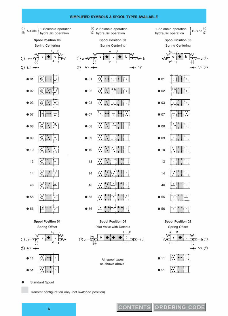
SIMPLIFIED SYMBOLS & SPOOL TYPES AVAILABLE
6
qw A-Side
1-Solenoid operation
hydraulic operationkSpool Position 06
Spring Centering
qw
2-Solenoid operation
hydraulic operation
Spool Position 03
Spring Centering
qwB-Side
1-Solenoid operation
hydraulic operation kSpool Position 05
Spring Centering
x 01
x 02
x 03
x 07
x 08
x 09
x 10
13
14
46
x 55
x 56
x 11
x 51
x 01
x 02
x 03
x 07
x 08
x 09
x 10
13
14
46
x 55
x 56
x 01
x 02
x 03
x 07
x 08
x 09
x 10
13
14
46
x 55
x 56
x 11
x 51
All spool types
as shown above!
Spool Position 01
Spring Offset
Spool Position 04
Pilot Valve with Detents
Spool Position 02
Spring Offset
x Standard Spool
Transfer configuration only (not switched position)
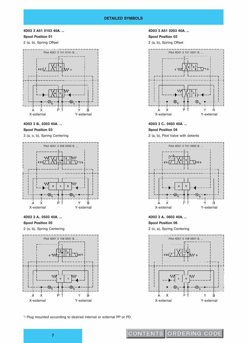
DETAILED SYMBOLS
7
4D03 3 A51 0103 40A. ...
Spool Position 01
2 (a, b), Spring Offset
4D03 3 B.. 0303 40A. ...
Spool Position 03
3 (a, o, b), Spring Centering
4D03 3 A.. 0503 40A. ...
Spool Position 05
2 (o, b), Spring Centering
X-external Y-external
X-external Y-external
X-external Y-external
Pilot 4D01 3 151 0101 B. ...
Pilot 4D01 3 208 0302 B. ...
Pilot 4D01 3 108 0501 B. ...
4D03 3 A51 0203 40A. ...
Spool Position 02
2 (a, b), Spring Offset
4D03 3 C.. 0403 40A. ...
Spool Position 04
2 (a, b), Pilot Valve with detents
4D03 3 A.. 0603 40A. ...
Spool Position 06
2 (o, a), Spring Centering
X-external Y-external
X-external Y-external
X-external Y-external
1) Plug mounted according to desired internal or external PP or PD.
Pilot 4D01 3 151 0201 B. ...
Pilot 4D01 3 751 0902 B. ...
Pilot 4D01 3 108 0601 B. ...
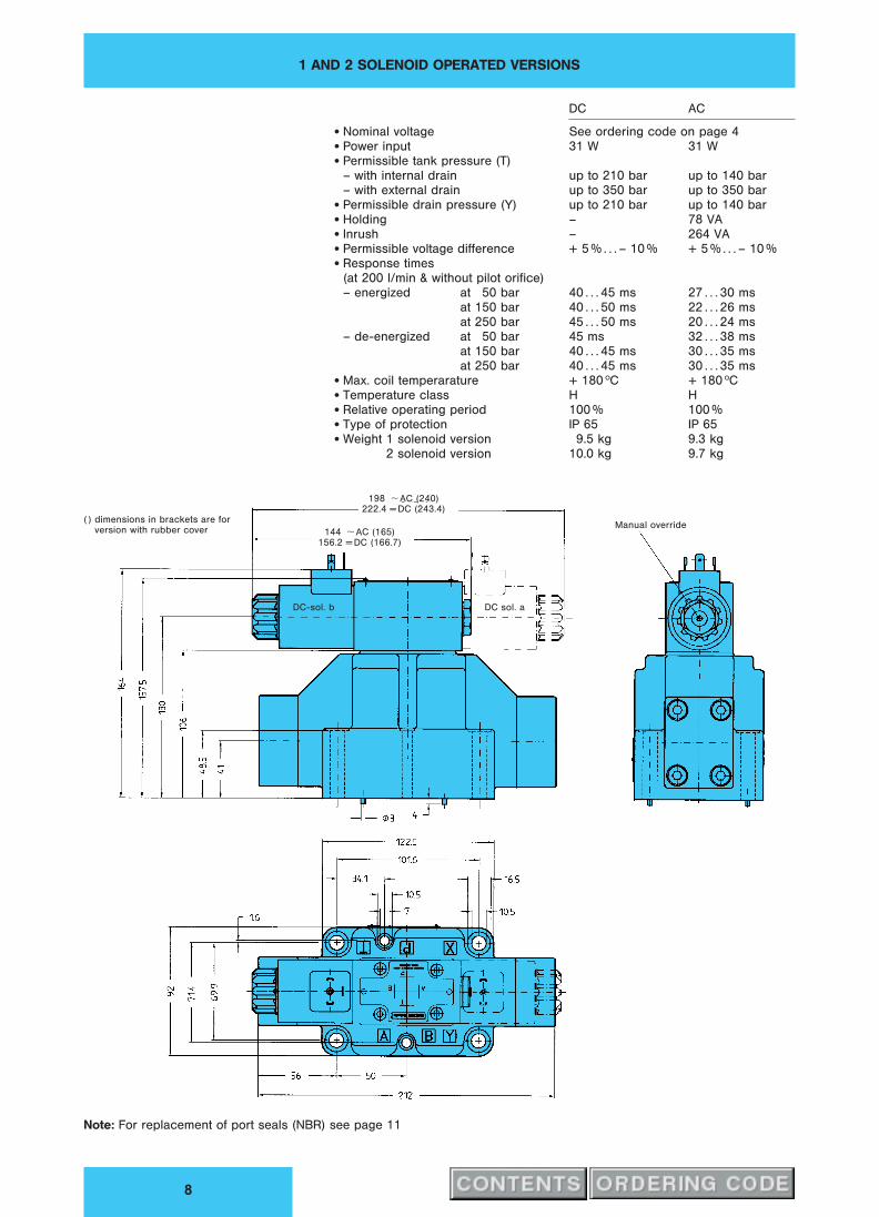
1 AND 2 SOLENOID OPERATED VERSIONS
8
DC AC
x Nominal voltage See ordering code on page 4x Power input 31 W 31 Wx Permissible tank pressure (T)
– with internal drain up to 210 bar up to 140 bar
– with external drain up to 350 bar up to 350 barx Permissible drain pressure (Y) up to 210 bar up to 140 barx Holding – 78 VAx Inrush – 264 VAx Permissible voltage difference + 5 % . . . – 10 % + 5 % . . . – 10 %x Response times
(at 200 l/min & without pilot orifice)
– energized at 50 bar 40 . . . 45 ms 27 . . . 30 ms
at 150 bar 40 . . . 50 ms 22 . . . 26 ms
at 250 bar 45 . . . 50 ms 20 . . . 24 ms
– de-energized at 50 bar 45 ms 32 . . . 38 ms
at 150 bar 40 . . . 45 ms 30 . . . 35 ms
at 250 bar 40 . . . 45 ms 30 . . . 35 msx Max. coil temperarature + 180 hC + 180 hCx Temperature class H Hx Relative operating period 100 % 100 %x Type of protection IP 65 IP 65x Weight 1 solenoid version 9.5 kg 9.3 kg
2 solenoid version 10.0 kg 9.7 kg
198 Ù AC (240)
222.4 = DC (243.4)
144 Ù AC (165)
156.2 = DC (166.7)
( ) dimensions in brackets are for
version with rubber coverManual override
DC-sol. b DC sol. a
Note: For replacement of port seals (NBR) see page 11
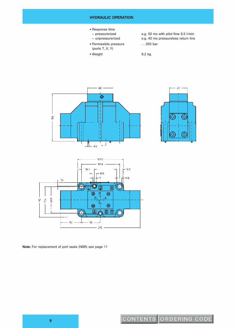
HYDRAULIC OPERATION
9
x Response time
– pressurerized e.g. 50 ms with pilot flow 6.5 l/min
– unpressurerized e.g. 40 ms pressureless return line
x Permissible pressure . . . 350 bar
(ports T, X, Y)
x Weight 8.2 kg
Note: For replacement of port seals (NBR) see page 11

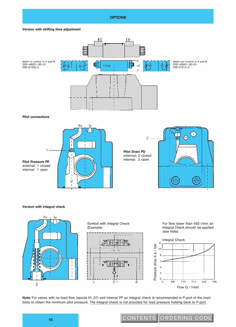
OPTIONS
10
Version with shifting time adjustment
Meter-in control in A and B
ZRD–ABZ01–S0–D1
098–91058–0
Meter-out control in A and B
ZRD–ABA01–S0–D1
098–91014–01.3 kg
Pilot connections
Pilot Pressure PP
external: 1 closed
internal: 1 open
Pilot Drain PD
external: 2 closed
internal: 2 open
Version with integral check
Symbol with Integral Check
(Example)
Integral Check
Flow Q / l/min
Pre
ssure
dro
p„
p/
bar
Note: For valves with no-load flow (spools 0, 07) and internal PP an integral check is recommended in P-port of the main
body to obtain the minimum pilot pressure. The integral check is not provided for load pressure holding back to P-port.

MOUNTING CONFIGURATION, PANEL OPENING
11
Mounting configuration conform to ISO 4401
Block mounting face
Flatness 0.01 mm/100 mm length
Surface finish 0.8
B
Portings
P = Pressure port
T = Tank port
A & B = Actuator ports
X = Pilot port for external PP: pilot operated valves
= Pilot port for hydr. operated valves
Y = Drain port for external PD: pilot operated valves
= Pilot port for hydr. operated valves
NBR-Seals
A, B, P, T 23.47 x 2.62 691–00119–0
X, Y 9.25 x 1.78 691–00012–0
Panel opening
for subplate G 3⁄4HH
Panel opening
for subplate G 1HH

SUBPLATES
12
Subplate G 3⁄4HH (mount. configuration conform to ISO 4401) Weight: ≈ 3.5 kg
Not to be used
with 4D03
Subplate G 1HH (mount. configuration accord. to CETOP, ISO and DIN) Weight: ≈ 8.3 kg
Not to be used
with 4D03
Please note:
Mounting screws are included in subplate order.
For valves ordered without subplate, mounting
screws must be ordered separately.
Mounting screws Order-No.
(4) M 10 x 65 DIN 912; 10.9 700–71449–8
(2) M 6 x 65 DIN 912; 10.9 700–70105–8
Torque 50 Nm for M10
13 Nm for M6
Model-No. Order-No. d1 (A, B, P, T) d2 d3 (X, Y) d4 d5 d6
SS–B–12–G 121–L S26–58610-0 G 3⁄4HH 41; 0.8 dp. G 1⁄4HH 23; 0.8 dp. M 10 M 6
SS–B–16–G 123–L S26–58611-0 G 1HH 47; 0.8 dp. G 1⁄4HH 23; 0.8 dp. M 10 M 6
ACCESSORIES
13
PLUG-IN CONNECTORS
CONFIRMING TO ISO 4400
36
Versions A-Side (grey) B-Side (black)
Standard <250 V PG 11 167–01007–8 167–01008–8
with LED (red) 15 . . . 30 V 167–01100–8 167–01101–8
with bridge rectifier 12 . . . 250 V 167–01076–8 167–01014–8
Note: Plug-in connectors to be ordered as separate items.
The product described is subject to continual development and the manufacturer reserves the right to change the specifications without notice.

Publ. 4–EN 371–A
DENISON HYDRAULICSDirectional Control Valves
Series 4D06 – Cetop 08
FEATURES, SYMBOL, GENERAL
2
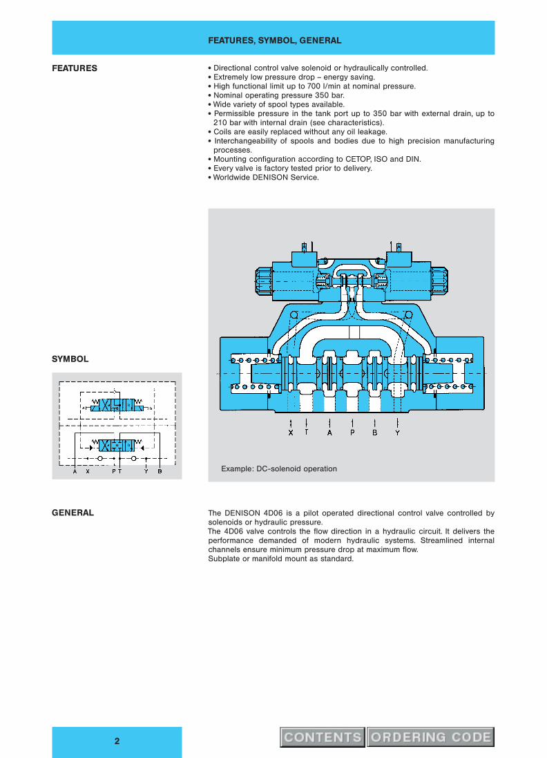
Example: DC-solenoid operation
FEATURES x Directional control valve solenoid or hydraulically controlled.x Extremely low pressure drop – energy saving.x High functional limit up to 700 l/min at nominal pressure.x Nominal operating pressure 350 bar.x Wide variety of spool types available.x Permissible pressure in the tank port up to 350 bar with external drain, up to
210 bar with internal drain (see characteristics).x Coils are easily replaced without any oil leakage.x Interchangeability of spools and bodies due to high precision manufacturing
processes.x Mounting configuration according to CETOP, ISO and DIN.x Every valve is factory tested prior to delivery.x Worldwide DENISON Service.
SYMBOL
GENERAL The DENISON 4D06 is a pilot operated directional control valve controlled by
solenoids or hydraulic pressure.
The 4D06 valve controls the flow direction in a hydraulic circuit. It delivers the
performance demanded of modern hydraulic systems. Streamlined internal
channels ensure minimum pressure drop at maximum flow.
Subplate or manifold mount as standard.
OPERATION, PILOT VALVE ORIFICE, CHARACTERISTICS
3
OPERATION The electrically operated 4-way valve 4D06 consists of a main body and a solenoid
operated pilot valve. The energized solenoid shifts the pilot control spool, thus
directing fluid to one end of the main spool, and moving it to the desired position.
Fluid can then flow e.g. from port P to either port A or B whilst the alternate port (B or
A) is connected to the tank line. The necessary pilot pressure can be obtained
internally from the system port P or from an external pressure supply connected to
port X.
De-energizing the solenoid allows both the pilot control and the main spool to return
to their neutral positions.
The hydraulically operated version may be remotely controlled by an external pilot
valve.
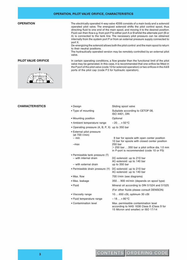
PILOT VALVE ORIFICE In certain operating conditions, a flow greater than the functional limit of the pilot
valve may be generated. In this case, it is recommended that one orifice be fitted in
the Pport of the pilot valve (code 10 for solenoid operation) or two orifices in the A&B
ports of the pilot cap (code P 3 for hydraulic operation).
CHARACTERISTICS x Design Sliding spool valve
x Type of mounting Subplate according to CETOP 08,
ISO 4401, DIN
x Mounting position Optional
x Ambient temperature range – 20 . . . + 50 hC
x Operating pressure (A, B, P, X) up to 350 bar
x External pilot pressure
(at 700 l/min)
– min 9 bar for spools with open center position
10 bar for spools with closed center position
–max 250 bar
> 250 bar . . . 350 bar a pilot orifice dia. .0 mm
in P-port is recommended (code 10 or P3)
x Permissible tank pressure (T)
– with internal drain DC-solenoid: up to 210 bar
AC-solenoid: up to 140 bar
– with external drain up to 350 bar
x Permissible drain pressure (Y) DC-solenoid: up to 210 bar
AC-solenoid: up to 140 bar
x Max. flow 700 l/min (see diagrams)
x Max. leakage 350 . . . 900 ml/min (depends on spool type)
x Fluid Mineral oil according to DIN 51524 and 51525
(For other fluids please consult DENISON)
x Viscosity range 10 . . . 650 cSt, optimum 30 cSt
x Fluid temperature range – 18 . . . + 80 hC
x Contamination level Max. permissible contamination level
according to NAS 1638 Class 8 (Class 9 for
15 Micron and smaller) or ISO 17/14

ORDERING CODE
4
Model No.: 4D06 . .. .. . . A ... .. .. ..– 3 – 03 – –
Series
06 = Cetop 08
Control
A = Pilot operated, 1 solenoid (4D01)
B = Pilot operated, 2 solenoids (4D01)
C = Pilot operated, 2 solenoids (4D01)
pilot valve: 2 pos. detents
0 = Hydraulic operation
Spool Type
refer to pages 5 and 6
Spool Position
01 = 2 (a, b ), Spring offset to pos. ”b”, energized to ”a”
02 = 2 (a, b ), Spring offset to pos. ”a”, energized to ”b”
03 = 3 (a, o, b), Spring centered pos. ”o”
04 = 2 (a, b), Spool is not centered, energized to ”a” or ”b”
(pilot valve with detents)
05 = 2 (o, b), Spring centered pos. ”o”, energized to ”b”
06 = 2 (o, a), Spring centered pos. ”o”, energized to ”a”
Pilot Connection
0 = External PP, external PD (for hydraulic operation)
1 = Internal PP, internal PD 1)
2 = Internal PP, external PD 1)
3 = External PP, internal PD
4 = External PP, external PD
Main Valve Accessories
0 = without
1 = Shifting time adjustment (meter-in control)
2 = Shifting time adjustment (meter-out control)
6 = Shifting time adjustment (meter-in control) & integral check in ”P” 1)
8 = Shifting time adjustment (meter-out control) & integral check in ”P” 1)
4 = Integral check in ”P” 1)
Design Letter
Seal Class
1 = NBR-seals (Standard)
5 = FPM-seals (Viton`)
Solenoid Voltage
G0R = 12 V
G0Q = 24 V DC
G0D = 27 V
W01 = 115 V / 60 Hz
W02 = 230 V / 60 HzAC
W06 = 115 V / 50 Hz
W07 = 230 V / 50 Hzk k
Order information for plug-in connectors see page 13
Pilot Accessories / Modifications
10 = 1.0 mm orifice in P-port; for solenoid with manual override
1032 = 1.0 mm orifice in P-port; for solenoid without manual override
1052 = 1.0 mm orifice in P-port; for solenoid with manual override; with rubber cover
P3 = 1.0 mm orifices in A & B-ports of the cap; for hydraulic operation only (control code 0)
1) Note:
For valves with no-load flow (spools 0, 07) and internal PP an integral check is recommended in P-port of the main body
to obtain the minimum pilot pressure. The integral check is not provided for load pressure holding back to P-port.
SPOOL TYPES, PRESSURE DROP, FUNCTIONAL LIMITS
5
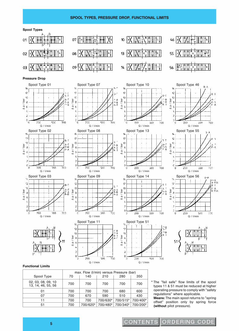
Spool Types
Pressure Drop
Spool Type 01 Spool Type 07 Spool Type 10 Spool Type 46
Spool Type 02 Spool Type 08 Spool Type 13 Spool Type 55
Spool Type 03 Spool Type 09 Spool Type 14 Spool Type 56
Spool Type 11 Spool Type 51
Q / l/min Q / l/min Q / l/min Q / l/min
Q / l/min Q / l/min Q / l/min Q / l/min
Q / l/min Q / l/min Q / l/min Q / l/min
Q / l/min Q / l/min
„p
/b
ar
„p
/b
ar
„p
/b
ar
„p
/b
ar
„p
/b
ar
„p
/b
ar
„p
/b
ar
„p
/b
ar
„p
/b
ar
„p
/b
ar
„p
/b
ar
„p
/b
ar
„p
/b
ar
„p
/b
ar
Functional Limits
max. Flow (l/min) versus Pressure (bar)
Spool Type 70 140 210 280 350
02, 03, 08, 09, 10700 700 700 700 700
13, 14, 46, 55, 56
01 700 700 700 680 600
07 700 670 590 510 430
11 700 700 700/630* 700/515* 700/400*
51 700 700/620* 700/480* 700/340* 700/200*
* The ”fail safe” flow limits of the spool
types 11 & 51 must be reduced at higher
operating pressure to comply with ”safety
regulations” where applicable.
Means: The main spool returns to ”spring
offset” position only by spring force
(without pilot pressure).
SIMPLIFIED SYMBOLS & SPOOL TYPES AVAILABLE
6
qw A-Side
1-Solenoid operation
hydraulic operationkSpool Position 06
Spring Centering
qw
2-Solenoid operation
hydraulic operation
Spool Position 03
Spring Centering
qwB-Side
1-Solenoid operation
hydraulic operation kSpool Position 05
Spring Centering
x 01
x 02
x 03
x 07
x 08
x 09
x 10
13
14
46
x 55
x 56
x 11
x 51
x 01
x 02
x 03
x 07
x 08
x 09
x 10
13
14
46
x 55
x 56
x 01
x 02
x 03
x 07
x 08
x 09
x 10
13
14
46
x 55
x 56
x 11
x 51
All spool types
as shown above!
Spool Position 01
Spring Offset
Spool Position 04
Pilot Valve with Detents
Spool Position 02
Spring Offset
x Standard Spool
Transfer configuration only (not switched position)

DETAILED SYMBOLS
7
4D06 3 A51 0103 40A. ...
Spool Position 01
2 (a, b), Spring Offset
4D06 3 B.. 0303 40A. ...
Spool Position 03
3 (a, o, b), Spring Centering
4D06 3 A.. 0503 40A. ...
Spool Position 05
2 (o, b), Spring Centering
X-external Y-external
X-external Y-external
X-external Y-external
Pilot 4D01 3 151 0101 B. ...
Pilot 4D01 3 208 0302 B. ...
Pilot 4D01 3 108 0501 B. ...
4D06 3 A51 0203 40A. ...
Spool Position 02
2 (a, b), Spring Offset
4D06 3 C.. 0403 40A. ...
Spool Position 04
2 (a, b), Pilot Valve with detents
4D06 3 A.. 0603 40A. ...
Spool Position 06
2 (o, a), Spring Centering
X-external Y-external
X-external Y-external
X-external Y-external
1) Plug mounted according to desired internal or external PP or PD.
Pilot 4D01 3 151 0201 B. ...
Pilot 4D01 3 751 0902 B. ...
Pilot 4D01 3 108 0601 B. ...

1 AND 2 SOLENOID OPERATED VERSIONS
8
DC AC
x Nominal voltage See ordering code on page 4
x Power input 31 W 31 W
x Holding – 78 VA
x Inrush – 264 VA
x Permissible voltage difference + 5 % . . . – 10 % + 5 % . . . – 10 %
x Response times
(at 400 l/min & without pilot orifice)
– energized at 50 bar 50 . . . 55 ms 35 . . . 40 ms
at 150 bar 50 . . . 55 ms 30 . . . 35 ms
at 250 bar 55 . . . 65 ms 28 . . . 30 ms
– de-energized at 50 bar 40 . . . 60 ms 40 . . . 55 ms
at 150 bar 32 . . . 55 ms 30 . . . 50 ms
at 250 bar 27 . . . 55 ms 28 . . . 50 ms
x Max. coil temperature + 180 hC + 180 hCx Temperature class H H
x Relative operating period 100 % 100 %
x Type of protection IP 65 IP 65
x Weight 1 solenoid version 17.2 kg 16.9 kg
2 solenoid version 17.6 kg 17.3 kg
198 Ù AC (240)
222.4 = DC (243.4)
144 Ù AC (165)
156.2 = DC (166.7)
( ) dimensions in brackets are for
version with rubber cover
Manual override
DC-sol. b DC-sol. a
Note: For replacement of port seals (NBR) see page 11

HYDRAULIC OPERATION
9
x Response time
– pressurerized e.g. 100 ms with pilot flow 6.5 l/min
– unpressurerized e.g. 80 ms with pressureless return line
x Weight 16.3 kg
Note: For replacement of port seals (NBR) see page 11
OPTIONS
10
Version with shifting time adjustment
Meter-in control in A and B
ZRD–ABZ01–S0–D1
098–91058–0
Meter-out control in A and B
ZRD–ABA01–S0–D1
098–91014–01.3 kg
Pilot connections
Pilot Pressure PP
external: 1 closed
internal: 1 open
Pilot Drain PD
external: 2 closed
internal: 2 open
Version with integral check
Symbol with Integral Check
(Example)
For flow lower than 450 l/min an
Integral Check should be applied
(see Note).
Integral Check
Flow Q / l/min
Pre
ssure
dro
p„
p/
bar
Note: For valves with no-load flow (spools 0, 07) and internal PP an integral check is recommended in P-port of the main
body to obtain the minimum pilot pressure. The integral check is not provided for load pressure holding back to P-port.

MOUNTING CONFIGURATION
11
Mounting configuration according to CETOP, ISO and DIN
Block mounting face
Flatness 0.01 mm/100 mm length
Surface finish 0.8
B
Portings
P = Pressure port
T = Tank port
A & B = Actuator ports
X = Pilot port for external PP: pilot operated valves
= Pilot port for hydr. operated valves
Y = Drain port for external PD: pilot operated valves
= Pilot port for hydr. operated valves
NBR-Seals
A, B, T 28.17 x 3.53 691–00216–0
P 31.34 x 3.53 691–00218–0
X, Y 20.29 x 2.62 691–00117–0
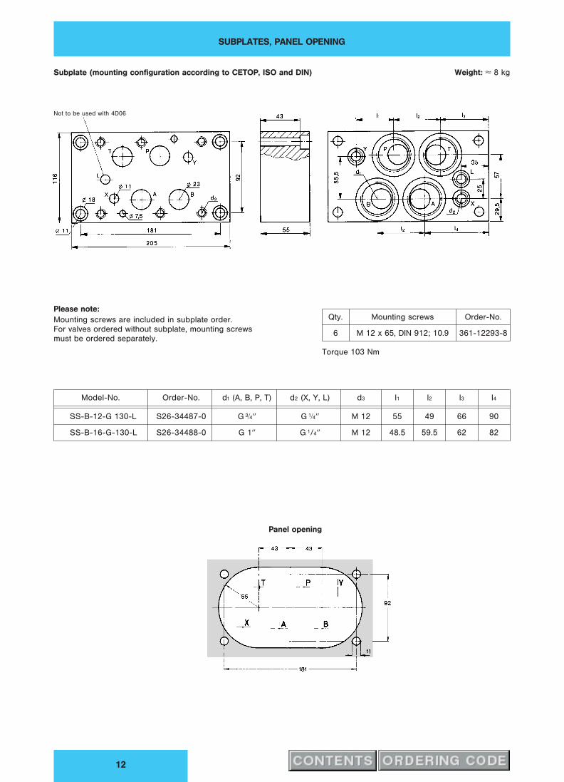
SUBPLATES, PANEL OPENING
12
Subplate (mounting configuration according to CETOP, ISO and DIN) Weight: ≈ 8 kg
Not to be used with 4D06
Please note:
Mounting screws are included in subplate order.
For valves ordered without subplate, mounting screws
must be ordered separately.
Panel opening
Qty. Mounting screws Order-No.
6 M 12 x 65, DIN 912; 10.9 361-12293-8
Torque 103 Nm
Model-No. Order-No. d (A, B, P, T) d2 (X, Y, L) d3 l1 l2 l3 l4
SS-B-12-G 130-L S26-34487-0 G 3⁄4HH G 1⁄4HH M 12 55 49 66 90
SS-B-16-G-130-L S26-34488-0 G 1HH G 1/4HH M 12 48.5 59.5 62 82

ACCESSORIES
13
PLUG-IN CONNECTORS
CONFIRMING TO ISO 4400
36
Versions A-Side (grey) B-Side (black)
Standard <250 V PG 11 167–01007–8 167–01008–8
with LED (red) 15 . . . 30 V 167–01100–8 167–01101–8
with bridge rectifier 12 . . . 250 V 167–01076–8 167–01014–8
Note: Plug-in connectors to be ordered as separate items.
The product described is subject to continual development and the manufacturer reserves the right to change the specifications without notice.