Embed Size (px)
Citation preview
Products Solutions Services
Brief Operating InstructionsDeltabar FMD71, FMD72Level measurement with electronic differentialpressureElectronic differential pressure transmitter withceramic and metal sensors
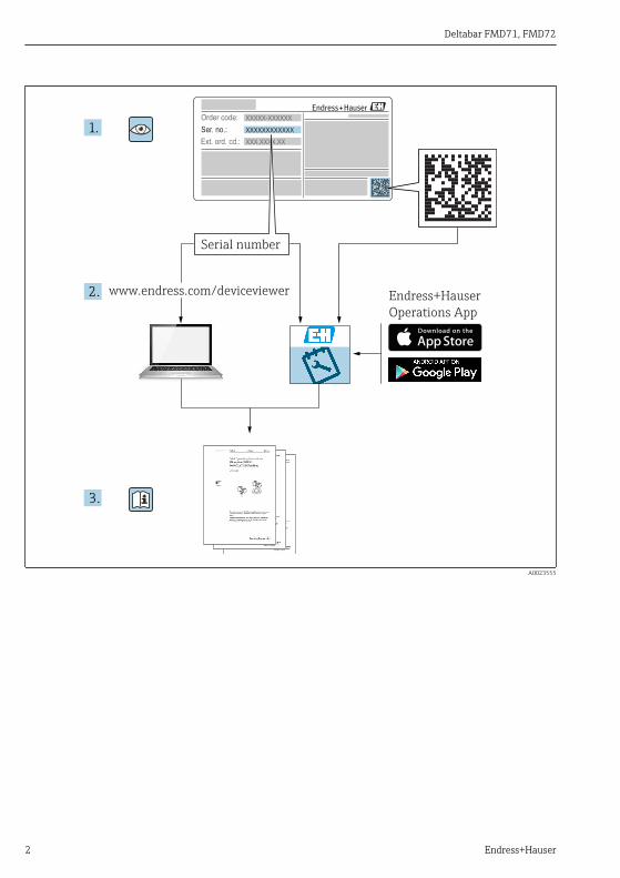
These Instructions are Brief Operating Instructions; they arenot a substitute for the Operating Instructions pertaining tothe device.Detailed information about the device can be found in theOperating Instructions and the other documentation:Available for all device versions via:– Internet: www.endress.com/deviceviewer– Smart phone/tablet: Endress+Hauser Operations App
KA01105P/00/EN/06.1771376030
Deltabar FMD71, FMD72
2 Endress+Hauser
Order code:
Ext. ord. cd.:
Ser. no.:
www.endress.com/deviceviewer Endress+Hauser
Operations App
XXXXXXXXXXXX
XXXXX-XXXXXX
XXX.XXXX.XX
Serial number
1.
3.
2.
A0023555
Deltabar FMD71, FMD72 Table of contents
Endress+Hauser 3
Table of contents1 Document information . . . . . . . . . . . . . . . . . . . . . . . . . . . . . . . . . . . . . . . . . . . . . . . . . . . . . . . . . . . . 41.1 Document function . . . . . . . . . . . . . . . . . . . . . . . . . . . . . . . . . . . . . . . . . . . . . . . . . . . . . . . . . . . . . . . . . . . . . 41.2 Symbols used . . . . . . . . . . . . . . . . . . . . . . . . . . . . . . . . . . . . . . . . . . . . . . . . . . . . . . . . . . . . . . . . . . . . . . . . . 41.3 Documentation . . . . . . . . . . . . . . . . . . . . . . . . . . . . . . . . . . . . . . . . . . . . . . . . . . . . . . . . . . . . . . . . . . . . . . . . 61.4 Terms and abbreviations . . . . . . . . . . . . . . . . . . . . . . . . . . . . . . . . . . . . . . . . . . . . . . . . . . . . . . . . . . . . . . . . . 81.5 Turn down calculation . . . . . . . . . . . . . . . . . . . . . . . . . . . . . . . . . . . . . . . . . . . . . . . . . . . . . . . . . . . . . . . . . . . 91.6 Registered trademarks . . . . . . . . . . . . . . . . . . . . . . . . . . . . . . . . . . . . . . . . . . . . . . . . . . . . . . . . . . . . . . . . . 10
2 Basic safety instructions . . . . . . . . . . . . . . . . . . . . . . . . . . . . . . . . . . . . . . . . . . . . . . . . . . . . . . . . . 102.1 Requirements concerning the staff . . . . . . . . . . . . . . . . . . . . . . . . . . . . . . . . . . . . . . . . . . . . . . . . . . . . . . . . 102.2 Designated use . . . . . . . . . . . . . . . . . . . . . . . . . . . . . . . . . . . . . . . . . . . . . . . . . . . . . . . . . . . . . . . . . . . . . . . 102.3 Workplace safety . . . . . . . . . . . . . . . . . . . . . . . . . . . . . . . . . . . . . . . . . . . . . . . . . . . . . . . . . . . . . . . . . . . . . 112.4 Operational safety . . . . . . . . . . . . . . . . . . . . . . . . . . . . . . . . . . . . . . . . . . . . . . . . . . . . . . . . . . . . . . . . . . . . . 112.5 Product safety . . . . . . . . . . . . . . . . . . . . . . . . . . . . . . . . . . . . . . . . . . . . . . . . . . . . . . . . . . . . . . . . . . . . . . . . 12
3 Product description . . . . . . . . . . . . . . . . . . . . . . . . . . . . . . . . . . . . . . . . . . . . . . . . . . . . . . . . . . . . . . 123.1 Product design . . . . . . . . . . . . . . . . . . . . . . . . . . . . . . . . . . . . . . . . . . . . . . . . . . . . . . . . . . . . . . . . . . . . . . . 12
4 Incoming acceptance and product identification . . . . . . . . . . . . . . . . . . . . . . . . . . . . . . . . . 134.1 Incoming acceptance . . . . . . . . . . . . . . . . . . . . . . . . . . . . . . . . . . . . . . . . . . . . . . . . . . . . . . . . . . . . . . . . . . . 134.2 Product identification . . . . . . . . . . . . . . . . . . . . . . . . . . . . . . . . . . . . . . . . . . . . . . . . . . . . . . . . . . . . . . . . . . 154.3 Nameplates . . . . . . . . . . . . . . . . . . . . . . . . . . . . . . . . . . . . . . . . . . . . . . . . . . . . . . . . . . . . . . . . . . . . . . . . . 164.4 Storage and transport . . . . . . . . . . . . . . . . . . . . . . . . . . . . . . . . . . . . . . . . . . . . . . . . . . . . . . . . . . . . . . . . . . 18
5 Installation . . . . . . . . . . . . . . . . . . . . . . . . . . . . . . . . . . . . . . . . . . . . . . . . . . . . . . . . . . . . . . . . . . . . . . 195.1 Mounting dimensions . . . . . . . . . . . . . . . . . . . . . . . . . . . . . . . . . . . . . . . . . . . . . . . . . . . . . . . . . . . . . . . . . . 195.2 Mounting location . . . . . . . . . . . . . . . . . . . . . . . . . . . . . . . . . . . . . . . . . . . . . . . . . . . . . . . . . . . . . . . . . . . . 195.3 Orientation . . . . . . . . . . . . . . . . . . . . . . . . . . . . . . . . . . . . . . . . . . . . . . . . . . . . . . . . . . . . . . . . . . . . . . . . . . 195.4 General installation instructions . . . . . . . . . . . . . . . . . . . . . . . . . . . . . . . . . . . . . . . . . . . . . . . . . . . . . . . . . . 195.5 Thermal insulation - FMD71 high-temperature version . . . . . . . . . . . . . . . . . . . . . . . . . . . . . . . . . . . . . . . . . 195.6 Installing the sensor modules . . . . . . . . . . . . . . . . . . . . . . . . . . . . . . . . . . . . . . . . . . . . . . . . . . . . . . . . . . . . 205.7 Mounting sensor modules with PVDF installation coupling . . . . . . . . . . . . . . . . . . . . . . . . . . . . . . . . . . . . . . . 215.8 Installing the transmitter . . . . . . . . . . . . . . . . . . . . . . . . . . . . . . . . . . . . . . . . . . . . . . . . . . . . . . . . . . . . . . . 215.9 Closing the housing cover . . . . . . . . . . . . . . . . . . . . . . . . . . . . . . . . . . . . . . . . . . . . . . . . . . . . . . . . . . . . . . . 215.10 Seal for flange mounting . . . . . . . . . . . . . . . . . . . . . . . . . . . . . . . . . . . . . . . . . . . . . . . . . . . . . . . . . . . . . . . . 225.11 Post-installation check . . . . . . . . . . . . . . . . . . . . . . . . . . . . . . . . . . . . . . . . . . . . . . . . . . . . . . . . . . . . . . . . . 22
6 Electrical connection . . . . . . . . . . . . . . . . . . . . . . . . . . . . . . . . . . . . . . . . . . . . . . . . . . . . . . . . . . . . 236.1 Connecting the sensor module LP to the sensor module HP . . . . . . . . . . . . . . . . . . . . . . . . . . . . . . . . . . . . . . 236.2 Connecting the sensor module HP to the transmitter . . . . . . . . . . . . . . . . . . . . . . . . . . . . . . . . . . . . . . . . . . . 246.3 Connecting the measuring unit . . . . . . . . . . . . . . . . . . . . . . . . . . . . . . . . . . . . . . . . . . . . . . . . . . . . . . . . . . . 266.4 Connection conditions . . . . . . . . . . . . . . . . . . . . . . . . . . . . . . . . . . . . . . . . . . . . . . . . . . . . . . . . . . . . . . . . . . 286.5 Connection data . . . . . . . . . . . . . . . . . . . . . . . . . . . . . . . . . . . . . . . . . . . . . . . . . . . . . . . . . . . . . . . . . . . . . . 286.6 Post-connection check . . . . . . . . . . . . . . . . . . . . . . . . . . . . . . . . . . . . . . . . . . . . . . . . . . . . . . . . . . . . . . . . . . 28
7 Operation options . . . . . . . . . . . . . . . . . . . . . . . . . . . . . . . . . . . . . . . . . . . . . . . . . . . . . . . . . . . . . . . 297.1 Operation without operating menu . . . . . . . . . . . . . . . . . . . . . . . . . . . . . . . . . . . . . . . . . . . . . . . . . . . . . . . . 297.2 Operation with an operating menu . . . . . . . . . . . . . . . . . . . . . . . . . . . . . . . . . . . . . . . . . . . . . . . . . . . . . . . . 317.3 Structure of the operating menu . . . . . . . . . . . . . . . . . . . . . . . . . . . . . . . . . . . . . . . . . . . . . . . . . . . . . . . . . . 327.4 Operating options . . . . . . . . . . . . . . . . . . . . . . . . . . . . . . . . . . . . . . . . . . . . . . . . . . . . . . . . . . . . . . . . . . . . . 337.5 Operating the device using onsite display (optional) . . . . . . . . . . . . . . . . . . . . . . . . . . . . . . . . . . . . . . . . . . . . 337.6 Operation using Endress+Hauser operating program . . . . . . . . . . . . . . . . . . . . . . . . . . . . . . . . . . . . . . . . . . . 367.7 Direct access to parameters . . . . . . . . . . . . . . . . . . . . . . . . . . . . . . . . . . . . . . . . . . . . . . . . . . . . . . . . . . . . . . 367.8 Locking/unlocking operation . . . . . . . . . . . . . . . . . . . . . . . . . . . . . . . . . . . . . . . . . . . . . . . . . . . . . . . . . . . . . 367.9 Resetting to factory settings (reset) . . . . . . . . . . . . . . . . . . . . . . . . . . . . . . . . . . . . . . . . . . . . . . . . . . . . . . . . 36
8 Integrating transmitter via HART® protocol . . . . . . . . . . . . . . . . . . . . . . . . . . . . . . . . . . . . . . 36
Document information Deltabar FMD71, FMD72
4 Endress+Hauser
9 Commissioning . . . . . . . . . . . . . . . . . . . . . . . . . . . . . . . . . . . . . . . . . . . . . . . . . . . . . . . . . . . . . . . . . . 379.1 Post-installation check and function check . . . . . . . . . . . . . . . . . . . . . . . . . . . . . . . . . . . . . . . . . . . . . . . . . . . 379.2 Unlocking/locking configuration . . . . . . . . . . . . . . . . . . . . . . . . . . . . . . . . . . . . . . . . . . . . . . . . . . . . . . . . . . 379.3 Commissioning without an operating menu . . . . . . . . . . . . . . . . . . . . . . . . . . . . . . . . . . . . . . . . . . . . . . . . . . 379.4 Commissioning with an operating menu . . . . . . . . . . . . . . . . . . . . . . . . . . . . . . . . . . . . . . . . . . . . . . . . . . . . 399.5 Language selection . . . . . . . . . . . . . . . . . . . . . . . . . . . . . . . . . . . . . . . . . . . . . . . . . . . . . . . . . . . . . . . . . . . . 399.6 Measuring mode selection . . . . . . . . . . . . . . . . . . . . . . . . . . . . . . . . . . . . . . . . . . . . . . . . . . . . . . . . . . . . . . . 409.7 Selecting the high-pressure side . . . . . . . . . . . . . . . . . . . . . . . . . . . . . . . . . . . . . . . . . . . . . . . . . . . . . . . . . . 409.8 Pressure unit selection . . . . . . . . . . . . . . . . . . . . . . . . . . . . . . . . . . . . . . . . . . . . . . . . . . . . . . . . . . . . . . . . . 419.9 Pos. zero adjust . . . . . . . . . . . . . . . . . . . . . . . . . . . . . . . . . . . . . . . . . . . . . . . . . . . . . . . . . . . . . . . . . . . . . . . 419.10 Configuring level measurement . . . . . . . . . . . . . . . . . . . . . . . . . . . . . . . . . . . . . . . . . . . . . . . . . . . . . . . . . . . 439.11 Linearization . . . . . . . . . . . . . . . . . . . . . . . . . . . . . . . . . . . . . . . . . . . . . . . . . . . . . . . . . . . . . . . . . . . . . . . . 469.12 Configuring pressure measurement . . . . . . . . . . . . . . . . . . . . . . . . . . . . . . . . . . . . . . . . . . . . . . . . . . . . . . . . 46
1 Document information
1.1 Document functionThe Brief Operating Instructions contain all the essential information from incomingacceptance to initial commissioning.
1.2 Symbols used
1.2.1 Safety symbols
Symbol Meaning
DANGER
DANGER!This symbol alerts you to a dangerous situation. Failure to avoid this situation will result inserious or fatal injury.
WARNING
WARNING!This symbol alerts you to a dangerous situation. Failure to avoid this situation can result inserious or fatal injury.
CAUTION
CAUTION!This symbol alerts you to a dangerous situation. Failure to avoid this situation can result inminor or medium injury.
NOTICE
NOTE!This symbol contains information on procedures and other facts which do not result inpersonal injury.
1.2.2 Electrical symbols
Symbol Meaning Symbol Meaning
Direct current Alternating current
Direct current and alternating current Ground connectionA grounded terminal which, as far asthe operator is concerned, is groundedvia a grounding system.
Deltabar FMD71, FMD72 Document information
Endress+Hauser 5
Symbol Meaning
Protective Earth (PE)A terminal which must be connected to ground prior to establishing any other connections.
The ground terminals are situated inside and outside the device:• Inner ground terminal: Connects the protectiv earth to the mains supply.• Outer ground terminal: Connects the device to the plant grounding system.
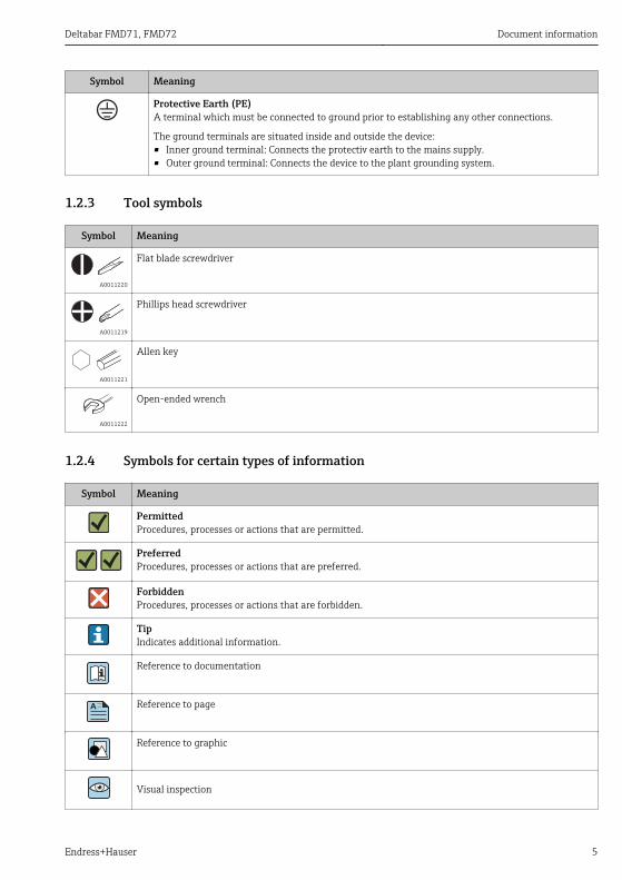
1.2.3 Tool symbols
Symbol Meaning
A0011220
Flat blade screwdriver
A0011219
Phillips head screwdriver
A0011221
Allen key
A0011222
Open-ended wrench
1.2.4 Symbols for certain types of information
Symbol Meaning
PermittedProcedures, processes or actions that are permitted.
PreferredProcedures, processes or actions that are preferred.
ForbiddenProcedures, processes or actions that are forbidden.
TipIndicates additional information.
Reference to documentation
A Reference to page
Reference to graphic
Visual inspection
Document information Deltabar FMD71, FMD72
6 Endress+Hauser
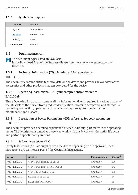
1.2.5 Symbols in graphics
Symbol Meaning
1, 2, 3 ... Item numbers
, …,1. 2. 3. Series of steps
A, B, C, ... Views
A-A, B-B, C-C, ... Sections
1.3 DocumentationThe document types listed are available:In the Download Area of the Endress+Hauser Internet site: www.endress.com →Download
1.3.1 Technical Information (TI): planning aid for your deviceTI01033P:The document contains all the technical data on the device and provides an overview of theaccessories and other products that can be ordered for the device.
1.3.2 Operating Instructions (BA): your comprehensive referenceBA01044P:These Operating Instructions contain all the information that is required in various phases ofthe life cycle of the device: from product identification, incoming acceptance and storage, tomounting, connection, operation and commissioning through to troubleshooting,maintenance and disposal.
1.3.3 Description of Device Parameters (GP): reference for your parametersGP01013P:The document provides a detailed explanation of each individual parameter in the operatingmenu. The description is aimed at those who work with the device over the entire life cycleand perform specific configurations.
1.3.4 Safety Instructions (XA)Safety Instructions (XA) are supplied with the device depending on the approval. Theseinstructions are an integral part of the Operating Instructions.
Device Directive Documentation Option 1)
FMD71, FMD72 ATEX II 1/2G Ex ia IIC T6 Ga/Gb XA00619P BA
FMD71, FMD72 ATEX II 1/2G Ex d [ia] IIC T6 Ga/Gb XA00620P BC
FMD71, FMD72 ATEX II 3G Ex nA IIC T6 GC XA00621P BD
FMD71, FMD72 IEC Ex ia IIC T6 Ga/Gb XA00622P IA
FMD71, FMD72 IEC Ex d [ia] IIC T6 Ga/Gb XA00623P IB

Deltabar FMD71, FMD72 Document information
Endress+Hauser 7
Device Directive Documentation Option 1)
FMD71, FMD72 CSA General Purpose - CD
FMD71, FMD72 NEPSI Ex ia IIC T4/T6 Ga/Gb XA01352P NA
FMD71, FMD72 NEPSI Ex d [ia] IIC T4/T6 Ga/Gb XA01353P NB
FMD71, FMD72 INMETRO Ex ia IIC T6...T4 Ga/Gb XA01378P MA
FMD71, FMD72 INMETRO Ex d [ia] IIC T6...T4 Ga/Gb XA01379P MC
FMD71, FMD72 EAC Ga/Gb Ex ia IIC T6...T4 XA01594P GA
FMD71, FMD72 EAC Ga/Gb Ex d [ia] IIC T6...T4 X XA01595P GB
FMD71 FM C/US IS Cl.I Div.1 Gr.A-D, AEx ia, Zone 0,1,2 XA00628P FA
FMD71 FM C/US XP AIS Cl.I Div.1 Gr.A-D, Exd [ia] Zone 0,1,2 XA00629P FB
FMD71 CSA C/US XP Cl.I Div.1 Gr.A-D, Ex d [ia], Zone 0,1,2 XA00631P CB
FMD71 FM C/US NI Cl.I Div.2 Gr.A-D, Zone 2 XA00668P FD
FMD71 CSA C/US NI, Cl.I Div. 2, Gr.A-D Cl.I, Zone 2, IIC XA00670P CC
FMD71 CSA C/US IS Cl.I Div.1 Gr.A-D, Ex ia Zone 0,1,2 XA00630P CA
FMD72 CSA C/US IS Cl.I Div.1 Gr.A-D, Ex ia Zone 0,1,2 XA00626P CA
FMD72 CSA C/US XP Cl.I Div.1 Gr.A-D, Ex d [ia], Zone 0,1,2 XA00627P CB
FMD72 CSA C/US NI, Cl.I Div.2 Gr.A-D, Zone 2 XA00671P CC
FMD72 FM C/US IS Cl.I Div.1 Gr.A-D, AEx ia, Zone 0,1,2 XA00624P FA
FMD72 FM C/US XP AIS Cl.I Div.1 Gr.A-D, Exd [ia] Zone 0,1,2 XA00625P FB
FMD72 FM C/US NI Cl.I Div.2 Gr.A-D, Zone 2 XA00669P FD
1) Product Configurator order code for "Approval"
The nameplate provides information on the Safety Instructions (XA) that are relevant forthe device.

Document information Deltabar FMD71, FMD72
8 Endress+Hauser
1.4 Terms and abbreviations
URL OPLMWPLRL
0
p
LRV URV
1
2
3
4
A0029505
Position Term/abbreviation
Explanation
1 OPL The OPL (over pressure limit = sensor overload limit) for the measuring devicedepends on the lowest-rated element, with regard to pressure, of the selectedcomponents, i.e. the process connection has to be taken into consideration in additionto the measuring cell. Also observe pressure-temperature dependency. For therelevant standards and additional notes, see the "Pressure specifications" section of theOperating Instructions.The OPL may only be applied for a limited period of time.
2 MWP The MWP (maximum working pressure) for the sensors depends on the lowest-ratedelement, with regard to pressure, of the selected components, i.e. the processconnection has to be taken into consideration in addition to the measuring cell. Alsoobserve pressure-temperature dependency. For the relevant standards and additionalnotes, see the "Pressure specifications" section of the Operating Instructions.The MWP may be applied at the device for an unlimited period.The MWP can also be found on the nameplate.
Deltabar FMD71, FMD72 Document information
Endress+Hauser 9
Position Term/abbreviation
Explanation
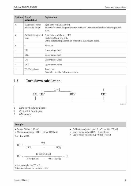
3 Maximum sensormeasuring range
Span between LRL and URLThis sensor measuring range is equivalent to the maximum calibratable/adjustablespan.
4 Calibrated/adjustedspan
Span between LRV and URVFactory setting: 0 to URLOther calibrated spans can be ordered as customized spans.
p - Pressure
- LRL Lower range limit
- URL Upper range limit
- LRV Lower range value
- URV Upper range value
- TD (Turn down) Turn downExample - see the following section.
1.5 Turn down calculation
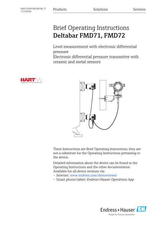
LRV URLURVLRL
1 = 2 3
A0029545
1 Calibrated/adjusted span2 Zero point-based span3 URL sensor
Example
• Sensor:10 bar (150 psi)• Upper range value (URL) = 10 bar (150 psi)
Turn down (TD):
• Calibrated/adjusted span: 0 to 5 bar (0 to 75 psi)• Lower range value (LRV) = 0 bar (0 psi)• Upper range value (URV) = 5 bar (75 psi)
TD =URL
|URV - LRV|
TD =10 bar (150 psi)
= 2|5 bar (75 psi) - 0 bar (0 psi)|
In this example, the TD is 2:1.This span is based on the zero point.

Basic safety instructions Deltabar FMD71, FMD72
10 Endress+Hauser
1.6 Registered trademarks
1.6.1 HART®Registered trademark of the FieldComm Group, Austin, USA
2 Basic safety instructions
2.1 Requirements concerning the staffThe staff must fulfill the following requirements for their tasks:‣ Trained staff: Must have a qualification which corresponds to their function and tasks.‣ Authorized by the plant operator.‣ Familiar with the national regulations.‣ Before starting their work: Must have read and understood all instructions in the operating
manual and supplementary documentation as well as the certificate (depending on theapplication).
‣ Must comply with all instructions and the regulatory framework.
2.2 Designated use
2.2.1 Application and mediaThe Deltabar FMD72 is a differential pressure transmitter for measuring differential pressureand level in pressurized tanks. The device has two sensor modules, which measure theoperating pressure (High Pressure HP and Low Pressure LP). The differential pressure/hydrostatic level is calculated in the transmitter unit. The sensor signal is transmitteddigitally. In addition, sensor temperatures and the individual process pressures present at therespective sensor modules can be individually evaluated and transmitted. If the limit valuesspecified in the "Technical Data" and the conditions listed in the instructions and additionaldocumentation are observed, the measuring device may be used for the followingmeasurements (process variables):
Measured process variables• Pressure HP and Pressure LP• Sensor temperature HP and sensor temperature LP• Transmitter temperature
Calculated process variables• Differential pressure• Level (level, volume or mass)
2.2.2 Incorrect useThe manufacturer is not liable for damage caused by improper or non-designated use.
Deltabar FMD71, FMD72 Basic safety instructions
Endress+Hauser 11
Verification for borderline cases:‣ For special fluids and fluids for cleaning, Endress+Hauser is glad to provide assistance in
verifying the corrosion resistance of fluid-wetted materials, but does not accept anywarranty or liability.
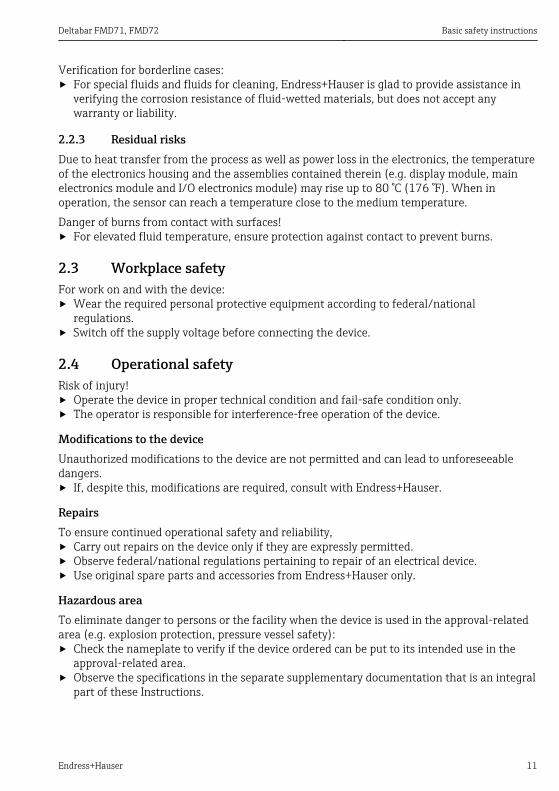
2.2.3 Residual risksDue to heat transfer from the process as well as power loss in the electronics, the temperatureof the electronics housing and the assemblies contained therein (e.g. display module, mainelectronics module and I/O electronics module) may rise up to 80 °C (176 °F). When inoperation, the sensor can reach a temperature close to the medium temperature.Danger of burns from contact with surfaces!‣ For elevated fluid temperature, ensure protection against contact to prevent burns.
2.3 Workplace safetyFor work on and with the device:‣ Wear the required personal protective equipment according to federal/national
regulations.‣ Switch off the supply voltage before connecting the device.
2.4 Operational safetyRisk of injury!‣ Operate the device in proper technical condition and fail-safe condition only.‣ The operator is responsible for interference-free operation of the device.
Modifications to the deviceUnauthorized modifications to the device are not permitted and can lead to unforeseeabledangers.‣ If, despite this, modifications are required, consult with Endress+Hauser.
RepairsTo ensure continued operational safety and reliability,‣ Carry out repairs on the device only if they are expressly permitted.‣ Observe federal/national regulations pertaining to repair of an electrical device.‣ Use original spare parts and accessories from Endress+Hauser only.
Hazardous areaTo eliminate danger to persons or the facility when the device is used in the approval-relatedarea (e.g. explosion protection, pressure vessel safety):‣ Check the nameplate to verify if the device ordered can be put to its intended use in the
approval-related area.‣ Observe the specifications in the separate supplementary documentation that is an integral
part of these Instructions.
Product description Deltabar FMD71, FMD72
12 Endress+Hauser
2.5 Product safetyThis measuring device is designed in accordance with good engineering practice to meet state-of-the-art safety requirements, has been tested, and left the factory in a condition in which itis safe to operate.It meets general safety standards and legal requirements. It also complies with the ECdirectives listed in the device-specific EC Declaration of Conformity. Endress+Hauser confirmsthis by affixing the CE mark to the device.
3 Product description
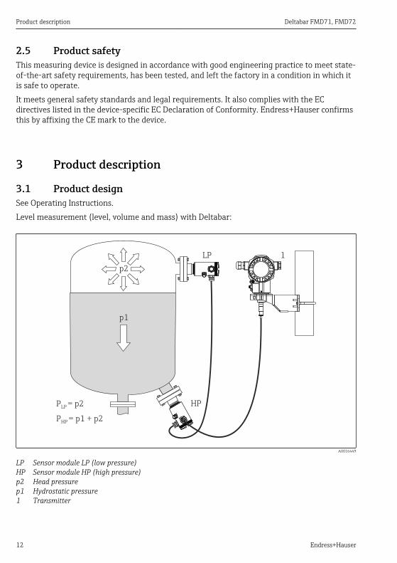
3.1 Product designSee Operating Instructions.Level measurement (level, volume and mass) with Deltabar:
LP 1
HP
p1
p2
P = p2LP
P = p1 + p2HP
A0016449
LP Sensor module LP (low pressure)HP Sensor module HP (high pressure)p2 Head pressurep1 Hydrostatic pressure1 Transmitter

Deltabar FMD71, FMD72 Incoming acceptance and product identification
Endress+Hauser 13
The FMD71/FMD72 is best suited to level measurement in vessels with pressure overlay or invacuum vessels and tanks, high distillation columns and other vessels with changing ambienttemperatures.The sensor module HP is mounted on the lower measuring connection and the sensor moduleLP is mounted above the maximum level. The transmitter can be mounted on pipes or wallswith the mounting bracket.The sensor signal is transmitted digitally. In addition, sensor temperatures and the individualprocess pressures present at the respective sensor modules can be individually evaluated andtransmitted.
NOTICEIncorrect sizing/order of sensor modules‣ In a closed system, please note that the sensor module is affected by the superimposed
head pressure (p2) in addition to the hydrostatic pressure (p1). This must be taken intoaccount when sizing the sensor module on the high-pressure side (HP).
4 Incoming acceptance and product identification
4.1 Incoming acceptance
A0028673
DELIVERY NOTE
1 = 2
A0016870
Is the order code on the delivery note (1) identical to the order code on theproduct sticker (2)?

Incoming acceptance and product identification Deltabar FMD71, FMD72
14 Endress+Hauser
A0016052
A0028673
A0016053
Are the goods undamaged?
A0028673
DELIVERY NOTE
Span
Ser. no.:Order code:
P
U:
Deltabar
Ext. order code:
Order Code:
Ser.-No.:
MWPSpan
U=
Mat.-
Dat.:
00
44
Mat.:
P
Ser. no.:
MWP
Sensor module Deltabar
A0016054
Do the data on the nameplate correspond to the order specifications andthe delivery note?
Deltabar FMD71, FMD72 Incoming acceptance and product identification
Endress+Hauser 15
A0028673
A0022106
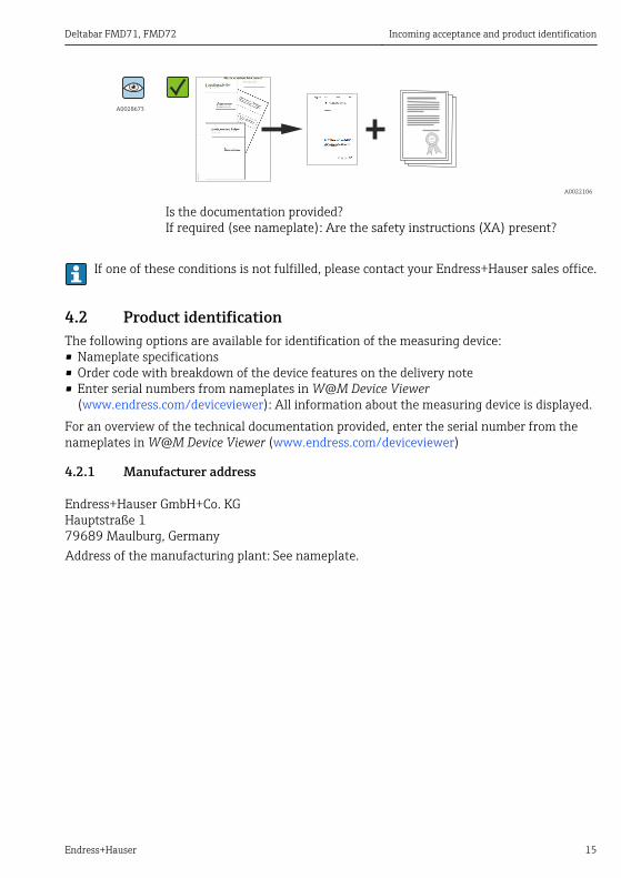
Is the documentation provided?If required (see nameplate): Are the safety instructions (XA) present?
If one of these conditions is not fulfilled, please contact your Endress+Hauser sales office.
4.2 Product identificationThe following options are available for identification of the measuring device:• Nameplate specifications• Order code with breakdown of the device features on the delivery note• Enter serial numbers from nameplates in W@M Device Viewer
(www.endress.com/deviceviewer): All information about the measuring device is displayed.For an overview of the technical documentation provided, enter the serial number from thenameplates in W@M Device Viewer (www.endress.com/deviceviewer)
4.2.1 Manufacturer address
Endress+Hauser GmbH+Co. KGHauptstraße 179689 Maulburg, GermanyAddress of the manufacturing plant: See nameplate.

Incoming acceptance and product identification Deltabar FMD71, FMD72
16 Endress+Hauser
4.3 Nameplates
4.3.1 Nameplates of the T14 transmitter housing
Ser. no.:Order code:
Ext. order code:
2 5
6
3
4
1
A0016056
1 Device name2 Order code (for re-orders)3 Extended order code (complete)4 Technical data5 Serial number (for identification)6 Manufacturer address
Additional nameplate for devices with Ex approval
2
1
A0021222
1 Approval-specific information2 Document number of Safety Instructions or drawing number
Additional nameplate for devices with PVDF process connection
1
A0022683
1 application limits
Deltabar FMD71, FMD72 Incoming acceptance and product identification
Endress+Hauser 17
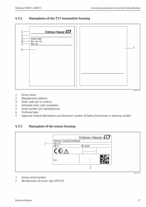
4.3.2 Nameplates of the T17 transmitter housing
2
7
345
6
1
Ser. no.:
Order code:
Ext. ord. cd.:
A0021552
1 Device name2 Manufacturer address3 Order code (for re-orders)4 Extended order code (complete)5 Serial number (for identification)6 Technical data7 Approval-related information and document number of Safety Instructions or drawing number
4.3.3 Nameplate of the sensor housing
00
44
Mat.:
P
Ser. no.:
MWP
Sensor module Deltabar
2
1
A0021224
1 Sensor serial number2 Identification of sensor type (HP/LP)
Incoming acceptance and product identification Deltabar FMD71, FMD72
18 Endress+Hauser
4.4 Storage and transport
4.4.1 Storage conditionsUse original packaging.Store the measuring device in clean and dry conditions and protect from damage caused byshocks (EN 837-2).
Storage temperature range–40 to +80 °C (–40 to +176 °F)
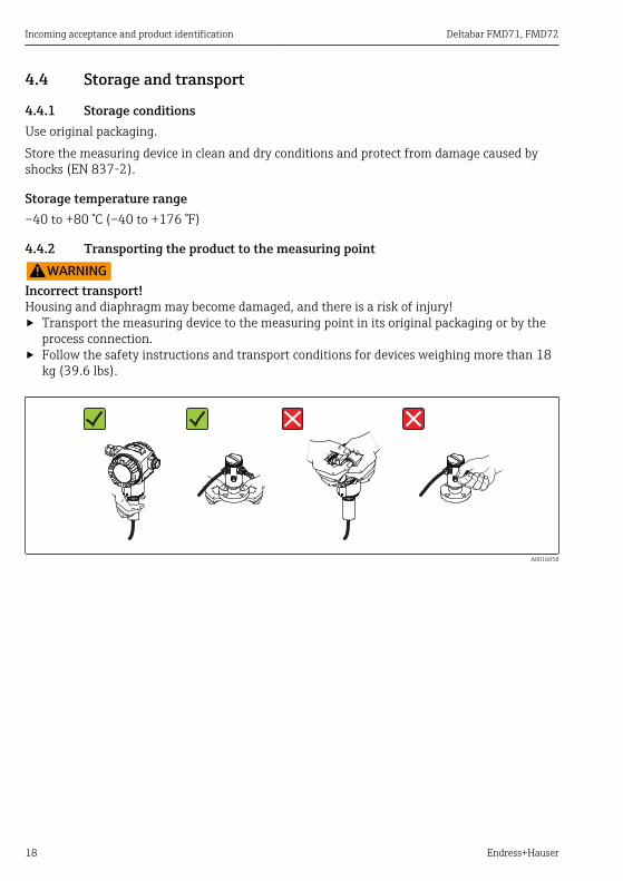
4.4.2 Transporting the product to the measuring point
LWARNINGIncorrect transport!Housing and diaphragm may become damaged, and there is a risk of injury!‣ Transport the measuring device to the measuring point in its original packaging or by the
process connection.‣ Follow the safety instructions and transport conditions for devices weighing more than 18
kg (39.6 lbs).
A0016058
Deltabar FMD71, FMD72 Installation
Endress+Hauser 19
5 Installation• Moisture must not penetrate the housing when mounting the device, establishing the
electrical connection and during operation.• When measuring in media containing solids, such as dirty liquids, installing separators and
drain valves is useful for capturing and removing sediment.• Do not clean or touch process isolating diaphragms with hard and/or pointed objects.• Do not remove process isolating diaphragm protection until shortly before installation.• Always firmly tighten the housing cover and the cable entries.• Point the cable and connector downwards where possible to prevent moisture from entering
(e.g. rain or condensation water).
5.1 Mounting dimensionsFor dimensions, see the "Mechanical construction" section in the Technical Information.
5.2 Mounting locationThe FMD71/FMD72 is best suited to level measurement in vessels with pressure overlay or invacuum vessels and tanks, high distillation columns and other vessels with changing ambienttemperatures.The sensor module HP is mounted on the lower measuring connection and the sensor moduleLP is mounted above the maximum level. The transmitter can be mounted on pipes or wallswith the mounting bracket.
5.3 Orientation• Transmitter: Any orientation.• Sensor modules: The orientation can cause a zero point shift .
This position-dependent zero point shift can be corrected directly at the device via theoperating key, and also in hazardous areas in the case of devices with external operation(position adjustment).
5.4 General installation instructionsMounting the sensor modules and transmitter is very easy• The housings of the sensor modules can be rotated up to 360°.• The transmitter is freely rotatable in the mounting bracket.The sensor modules and transmitter can be easily aligned when mounted.Your benefits• Easy mounting due to optimum alignment of housing• Easily accessible device operation• Optimum readability of the onsite display (optional)• Easy pipe installation due to optional alignment of the modules.
5.5 Thermal insulation - FMD71 high-temperature versionSee Operating Instructions.
Installation Deltabar FMD71, FMD72
20 Endress+Hauser
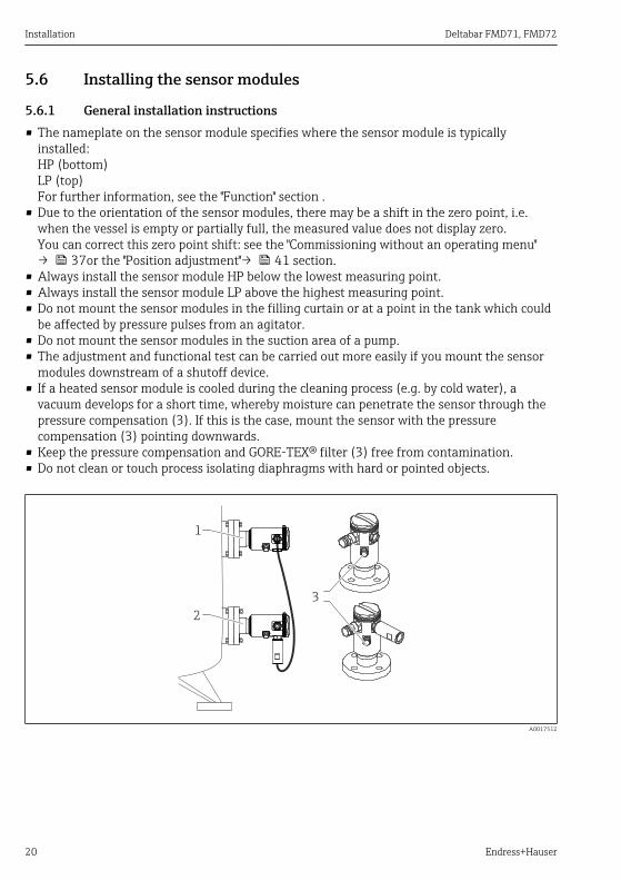
5.6 Installing the sensor modules
5.6.1 General installation instructions• The nameplate on the sensor module specifies where the sensor module is typically
installed:HP (bottom)LP (top)For further information, see the "Function" section .
• Due to the orientation of the sensor modules, there may be a shift in the zero point, i.e.when the vessel is empty or partially full, the measured value does not display zero.You can correct this zero point shift: see the "Commissioning without an operating menu"→ 37or the "Position adjustment"→ 41 section.
• Always install the sensor module HP below the lowest measuring point.• Always install the sensor module LP above the highest measuring point.• Do not mount the sensor modules in the filling curtain or at a point in the tank which could
be affected by pressure pulses from an agitator.• Do not mount the sensor modules in the suction area of a pump.• The adjustment and functional test can be carried out more easily if you mount the sensor
modules downstream of a shutoff device.• If a heated sensor module is cooled during the cleaning process (e.g. by cold water), a
vacuum develops for a short time, whereby moisture can penetrate the sensor through thepressure compensation (3). If this is the case, mount the sensor with the pressurecompensation (3) pointing downwards.
• Keep the pressure compensation and GORE-TEX® filter (3) free from contamination.• Do not clean or touch process isolating diaphragms with hard or pointed objects.
2
3
1
A0017512
Deltabar FMD71, FMD72 Installation
Endress+Hauser 21
5.7 Mounting sensor modules with PVDF installation couplingLWARNING
Risk of damage to process connection!Risk of injury!‣ Sensor modules with PVDF process connections with threaded connection must be
installed with the mounting bracket provided!
LWARNINGMaterial fatigue from pressure and temperature!Risk of injury due to bursting of parts! The thread can become lose if exposed to high pressureand temperature loads.‣ The integrity of the thread must be checked regularly and the thread may need to be
retightened with the maximum tightening torque of 7 Nm (5.16 lbf ft). Teflon tape isrecommended for sealing the ½" NPT thread.
The mounting bracket can be installed on pipes with a diameter of 1¼" to 2" or on walls.In the case of pipe mounting, the nuts on the bracket must be tightened uniformly with atorque of at least 5 Nm (3.69 lbf ft).• The mounting bracket is included in the delivery.• Ordering information:
Product Configurator order code for "Enclosed accessories", option "PA" oras a separate accessory (part no.: 71102216).
5.8 Installing the transmitterThe transmitter is installed with the mounting bracket supplied. The mounting bracket can beinstalled on pipes with a diameter of 1¼" to 2" or on walls.In the case of pipe mounting, the nuts on the bracket must be tightened uniformly with atorque of at least 5 Nm (3.69 lbf ft).The mounting bracket is included in the delivery.
5.8.1 Turning the display moduleSee "Operating Instructions".
5.9 Closing the housing coverNOTICE
The housing cover can no longer be closed.Damaged thread!‣ When closing the housing cover, please ensure that the thread of the cover and housing
are free from dirt, e.g. sand. If you feel any resistance when closing the cover, check thethread on both again to ensure that they are free from dirt.
Installation Deltabar FMD71, FMD72
22 Endress+Hauser
5.9.1 Closing the covers on the hygienic stainless steel housing (T17)The covers for the terminal compartment and electronics compartment are hooked into thehousing and closed with a screw in each case. These screws must be tightened finger-tight (2Nm (1.48 lbf ft)) to the stop to ensure that the covers are securely seated and leak-tight.
5.10 Seal for flange mountingNOTICE
Distorted measurement results.The seal is not allowed to press against the process isolating diaphragm as this could affectthe measurement result.‣ Ensure that the seal is not touching the process isolating diaphragm.
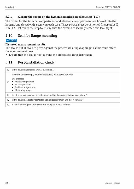
5.11 Post-installation check
Is the device undamaged (visual inspection)?
Does the device comply with the measuring point specifications?
For example:• Process temperature• Process pressure• Ambient temperature• Measuring range
Are the measuring point identification and labeling correct (visual inspection)?
Is the device adequately protected against precipitation and direct sunlight?
Are the securing screw and securing clamp tightened securely?
Deltabar FMD71, FMD72 Electrical connection
Endress+Hauser 23
6 Electrical connectionLWARNING
If the operating voltage is > 35 VDC: Dangerous contact voltage at terminals.Risk of electric shock!‣ In a wet environment, do not open the cover if voltage is present.
The sensor modules have a designation independent of the master/slave configuration.This indicates where the sensor module is typically installed:• Sensor module LP
LP = Low pressure; top• Sensor module HP
HP = High pressure; bottomFor further information, see the "Function" section .
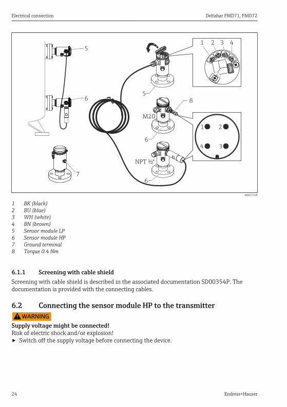
6.1 Connecting the sensor module LP to the sensor module HPLWARNING
Supply voltage might be connected!Risk of electric shock and/or explosion!‣ Switch off the supply voltage before connecting the device.
• Screw on the housing cover of the terminal compartment of the sensor module LP.• Guide the cable of the sensor module HP through the cable gland of the sensor module LP.
Use the shielded 4-wire cable that is provided. The wire ends are color-coded to match thecorresponding terminal.
• Connect device in accordance with the following diagrams.• Screw down housing cover.
Electrical connection Deltabar FMD71, FMD72
24 Endress+Hauser
6
7
5
5
6
2 3 4
34
1
21
6
NPT ½"
M20
8
A0017528
1 BK (black)2 BU (blue)3 WH (white)4 BN (brown)5 Sensor module LP6 Sensor module HP7 Ground terminal8 Torque 0.4 Nm
6.1.1 Screening with cable shieldScreening with cable shield is described in the associated documentation SD00354P. Thedocumentation is provided with the connecting cables.
6.2 Connecting the sensor module HP to the transmitterLWARNING
Supply voltage might be connected!Risk of electric shock and/or explosion!‣ Switch off the supply voltage before connecting the device.
Deltabar FMD71, FMD72 Electrical connection
Endress+Hauser 25
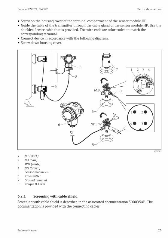
• Screw on the housing cover of the terminal compartment of the sensor module HP.• Guide the cable of the transmitter through the cable gland of the sensor module HP. Use the
shielded 4-wire cable that is provided. The wire ends are color-coded to match thecorresponding terminal.
• Connect device in accordance with the following diagram.• Screw down housing cover.
6
5
5
7 2 3 4
34
1
21
6
5
NPT ½"
M20 8
8
A0017529
1 BK (black)2 BU (blue)3 WH (white)4 BN (brown)5 Sensor module HP6 Transmitter7 Ground terminal8 Torque 0.4 Nm
6.2.1 Screening with cable shieldScreening with cable shield is described in the associated documentation SD00354P. Thedocumentation is provided with the connecting cables.
Electrical connection Deltabar FMD71, FMD72
26 Endress+Hauser
6.3 Connecting the measuring unit
6.3.1 Terminal assignment
LWARNINGSupply voltage might be connected!Risk of electric shock and/or explosion!‣ Switch off the supply voltage before connecting the device.
LWARNINGElectrical safety is compromised by an incorrect connection!‣ In accordance with IEC/EN61010 a separate circuit breaker must be provided for the
device .‣ When using the measuring device in hazardous areas, installation must comply with the
corresponding national standards and regulations and the Safety Instructions orInstallation or Control Drawings.
‣ All explosion protection data are given in separate documentation which is available uponrequest. The Ex documentation is supplied as standard with all devices approved for use inexplosion hazardous areas.
‣ Devices with integrated overvoltage protection must be grounded.‣ Protective circuits against reverse polarity, HF influences and overvoltage peaks are
integrated.
Connect the device in the following order:1. Check whether the supply voltage matches the supply voltage indicated on the
nameplate.2. Remove the housing cover.3. Guide cable through the gland.4. Connect device in accordance with the following diagram.5. Screw down housing cover.
Switch on supply voltage.
Deltabar FMD71, FMD72 Electrical connection
Endress+Hauser 27
4... 20mA Test
Test
Test
4... 20mA Test
1
8
67
2
3
4
5
A0019989
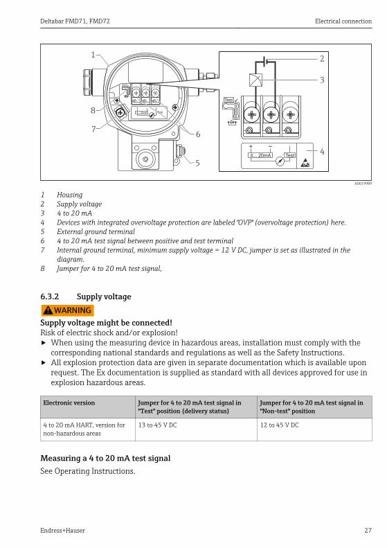
1 Housing2 Supply voltage3 4 to 20 mA4 Devices with integrated overvoltage protection are labeled "OVP" (overvoltage protection) here.5 External ground terminal6 4 to 20 mA test signal between positive and test terminal7 Internal ground terminal, minimum supply voltage = 12 V DC, jumper is set as illustrated in the
diagram.8 Jumper for 4 to 20 mA test signal,
6.3.2 Supply voltage
LWARNINGSupply voltage might be connected!Risk of electric shock and/or explosion!‣ When using the measuring device in hazardous areas, installation must comply with the
corresponding national standards and regulations as well as the Safety Instructions.‣ All explosion protection data are given in separate documentation which is available upon
request. The Ex documentation is supplied as standard with all devices approved for use inexplosion hazardous areas.
Electronic version Jumper for 4 to 20 mA test signal in"Test" position (delivery status)
Jumper for 4 to 20 mA test signal in"Non-test" position
4 to 20 mA HART, version fornon-hazardous areas
13 to 45 V DC 12 to 45 V DC
Measuring a 4 to 20 mA test signalSee Operating Instructions.

Electrical connection Deltabar FMD71, FMD72
28 Endress+Hauser
6.4 Connection conditions
6.4.1 Cable specificationPreferably use twisted, screened two-wire cable.
6.4.2 Cable specification for transmitter connectionSee Operating Instructions.
6.4.3 Cable entriesSee Operating Instructions.
6.4.4 Overvoltage protection
Standard versionThe standard version of the pressure instruments does not contain any special elements toprotect against overvoltage ("wire to ground"). Nevertheless the requirements of the applicableEMC standard EN 61000-4-5 (testing voltage 1kV EMC wire/ground) are met.
Optional overvoltage protectionSee Operating Instructions.
6.5 Connection dataSee Operating Instructions.
6.5.1 Maximum loadSee Operating Instructions.
When operating via a handheld terminal or via a PC with an operating program, aminimum communication resistance of 250 Ω must be taken into account.
6.6 Post-connection check
Is the device or cable undamaged (visual inspection)?
Do the cables comply with the requirements?
Do the mounted cables have adequate strain relief?
Are all the cable glands installed, tightened and sealed?
Does the supply voltage match the specifications on the nameplate?
Is the terminal assignment correct ?
If required: Has protective ground connection been established?
If supply voltage is present, is the device ready for operation and do values appear on the display module?
Are all the housing covers installed and tightened?
Is the securing clamp tightened correctly?
Deltabar FMD71, FMD72 Operation options
Endress+Hauser 29
7 Operation options
7.1 Operation without operating menu
7.1.1 Position of operating elements
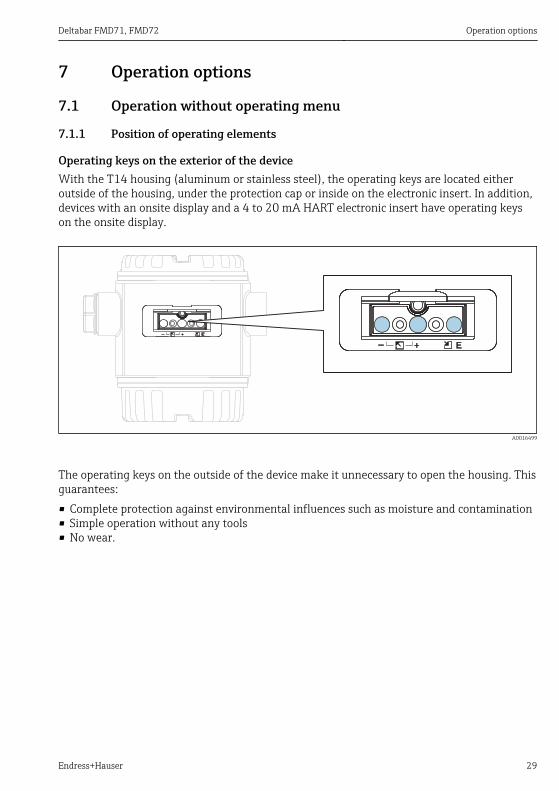
Operating keys on the exterior of the deviceWith the T14 housing (aluminum or stainless steel), the operating keys are located eitheroutside of the housing, under the protection cap or inside on the electronic insert. In addition,devices with an onsite display and a 4 to 20 mA HART electronic insert have operating keyson the onsite display.
A0016499
The operating keys on the outside of the device make it unnecessary to open the housing. Thisguarantees:• Complete protection against environmental influences such as moisture and contamination• Simple operation without any tools• No wear.
Operation options Deltabar FMD71, FMD72
30 Endress+Hauser
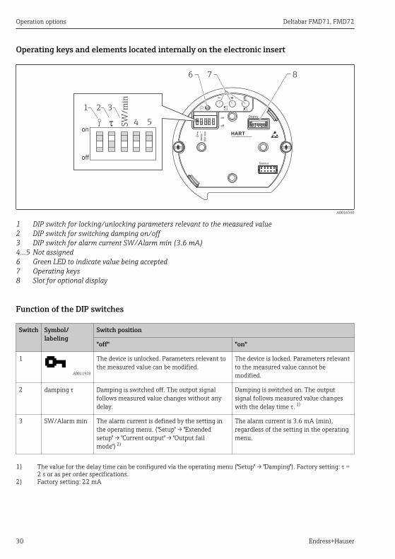
Operating keys and elements located internally on the electronic insert
on
off
dam
p.
Display
Sensor
HARTR
FIELD COMMUNICATION PROTOCOL
SW
/m
in
ton
off
1 2 3
4 5
6
SW
/m
in
7 8
A0016500
1 DIP switch for locking/unlocking parameters relevant to the measured value2 DIP switch for switching damping on/off3 DIP switch for alarm current SW/Alarm min (3.6 mA)4...5 Not assigned6 Green LED to indicate value being accepted7 Operating keys8 Slot for optional display
Function of the DIP switches
Switch Symbol/labeling
Switch position
"off" "on"
1
A0011978
The device is unlocked. Parameters relevant tothe measured value can be modified.
The device is locked. Parameters relevantto the measured value cannot bemodified.
2 damping t Damping is switched off. The output signalfollows measured value changes without anydelay.
Damping is switched on. The outputsignal follows measured value changeswith the delay time t. 1)
3 SW/Alarm min The alarm current is defined by the setting inthe operating menu. ("Setup" → "Extendedsetup" → "Current output" → "Output failmode") 2)
The alarm current is 3.6 mA (min),regardless of the setting in the operatingmenu.
1) The value for the delay time can be configured via the operating menu ("Setup" → "Damping"). Factory setting: t =2 s or as per order specifications.
2) Factory setting: 22 mA

Deltabar FMD71, FMD72 Operation options
Endress+Hauser 31
Function of the operating elements
Operating key(s) Meaning
A0017535
Press for at least 3seconds
Adopt lower range value. A referencepressure is present at the device.For a detailed description, see also "Pressuremeasuring mode" section (see "OperatingInstructions"), or "Level measuring mode"section.→ 37
A0017536
Press for at least 3seconds
Adopt upper range value. A referencepressure is present at the device.For a detailed description, see also "Pressuremeasuring mode" section (see "OperatingInstructions"), or "Level measuring mode"section → 37.
A0017537
Press for at least 3seconds
Position adjustment
A0017535
and
A0017536
and
A0017537
Press for at least 6seconds
Reset all parameters. The reset via operatingkeys corresponds to the software reset code7864.
7.2 Operation with an operating menu
7.2.1 Operation conceptOperation with an operating menu is based on an operation concept with "user roles" .
User role Meaning
Operator Operators are responsible for the devices during normal "operation". This is usually limited to readingprocess values either directly at the device or in a control room. If the work with the devices extendsbeyond value read-off tasks, the tasks involve simple, applicationspecific functions that are used inoperation. Should an error occur, these users simply forward the information on the errors but do notintervene themselves.
Maintenance Service engineers usually work with the devices in the phases following device commissioning. They areprimarily involved in maintenance and troubleshooting activities for which simple settings have to bemade at the device. Technicians work with the devices over the entire life cycle of the product. Thus,commissioning and advanced settings and configurations are some of the tasks they have to carry out.
Expert Experts work with the devices over the entire life cycle of the device, but, at times, have high devicerequirements. Individual parameters/functions from the overall functionality of the devices are requiredfor this purpose time and again. In addition to technical, process-oriented tasks, experts can alsoperform administrative tasks (e.g. user administration). "Experts" can access the entire parameter set.
Operation options Deltabar FMD71, FMD72
32 Endress+Hauser
7.3 Structure of the operating menu
User role Submenu Meaning/use
Operator Language Only consists of the "Language" parameter (000) where the operating language for thedevice is specified. The language can always be changed even if the device is locked.
Operator Display/operat.
Contains parameters that are needed to configure the measured value display (selectingthe values displayed, display format, display contrast, etc.). With this submenu, users canchange the measured value display without affecting the actual measurement.
Maintenance Setup Contains all the parameters that are needed to commission measuring operations. Thissubmenu has the following structure:• Standard setup parameters
A wide range of parameters, which can be used to configure a typical application, isavailable at the start. The measuring mode selected determines which parameters areavailable. After making settings for all these parameters, the measuring operationshould be completely configured in the majority of cases.
• "Extended setup" submenuThe "Extended setup" submenu contains additional parameters for more indepthconfiguration of the measurement operation to convert the measured value and toscale the output signal. This menu is split into additional submenus depending on themeasuring mode selected.
Maintenance Diagnosis Contains all the parameters that are needed to detect and analyze operating errors. Thissubmenu has the following structure:• Diagnostic list
Contains up to 10 error messages currently pending.• Event logbook
Contains the last 10 error messages (no longer pending).• Instrument info
Contains information on the device identification.• Measured values
Contains all the current measured values• Simulation
Is used to simulate pressure, level, current and alarm/warning.• Reset• Sensor LP• Sensor HP
Expert Expert Contains all the parameters of the device (including those in one of the submenus). The"Expert" submenu is structured by the function blocks of the device. It thus contains thefollowing submenus:• System
Contains all the device parameters that neither affect measurement nor integrationinto a distributed control system.
• MeasurementContains all the parameters for configuring the measurement.
• OutputContains all the parameters for configuring the current output.
• Communicationcontains all parameters for configuring the HART interface.
• DiagnosisContains all the parameters that are needed to detect and analyze operating errors.
Deltabar FMD71, FMD72 Operation options
Endress+Hauser 33
7.4 Operating options
7.4.1 Local operation
1
A0017650
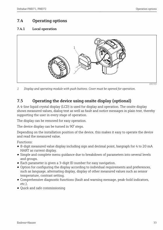
1 Display and operating module with push buttons. Cover must be opened for operation.
7.5 Operating the device using onsite display (optional)A 4-line liquid crystal display (LCD) is used for display and operation. The onsite displayshows measured values, dialog text as well as fault and notice messages in plain text, therebysupporting the user in every stage of operation.The display can be removed for easy operation.The device display can be turned in 90° steps.Depending on the installation position of the device, this makes it easy to operate the deviceand read the measured value.Functions:• 8-digit measured value display including sign and decimal point, bargraph for 4 to 20 mA
HART as current display.• Simple and complete menu guidance due to breakdown of parameters into several levels
and groups.• Each parameter is given a 3-digit ID number for easy navigation.• Option for configuring the display according to individual requirements and preferences,
such as language, alternating display, display of other measured values such as sensortemperature, contrast setting.
• Comprehensive diagnostic functions (fault and warning message, peak-hold indicators,etc.).
• Quick and safe commissioning
Operation options Deltabar FMD71, FMD72
34 Endress+Hauser
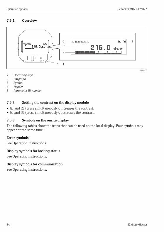
7.5.1 Overview
1
E+–
3
2
4 5
A0016498
1 Operating keys2 Bargraph3 Symbol4 Header5 Parameter ID number
7.5.2 Setting the contrast on the display module• and (press simultaneously): increases the contrast.• and (press simultaneously): decreases the contrast.
7.5.3 Symbols on the onsite displayThe following tables show the icons that can be used on the local display. Four symbols mayappear at the same time.
Error symbolsSee Operating Instructions.
Display symbols for locking statusSee Operating Instructions.
Display symbols for communicationSee Operating Instructions.
Deltabar FMD71, FMD72 Operation options
Endress+Hauser 35
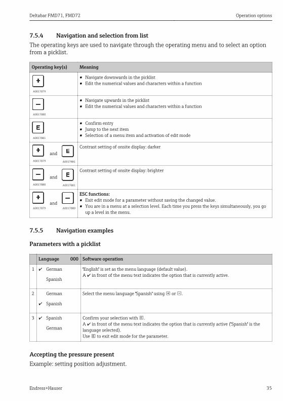
7.5.4 Navigation and selection from listThe operating keys are used to navigate through the operating menu and to select an optionfrom a picklist.
Operating key(s) Meaning
A0017879
• Navigate downwards in the picklist• Edit the numerical values and characters within a function
A0017880
• Navigate upwards in the picklist• Edit the numerical values and characters within a function
A0017881
• Confirm entry• Jump to the next item• Selection of a menu item and activation of edit mode
A0017879
and A0017881
Contrast setting of onsite display: darker
A0017880
and A0017881
Contrast setting of onsite display: brighter
A0017879and
A0017880
ESC functions:• Exit edit mode for a parameter without saving the changed value.• You are in a menu at a selection level. Each time you press the keys simultaneously, you go
up a level in the menu.
7.5.5 Navigation examples
Parameters with a picklist
Language 000 Software operation
1 German "English" is set as the menu language (default value).A in front of the menu text indicates the option that is currently active.
Spanish
2 German Select the menu language "Spanish" using or .
Spanish
3 Spanish Confirm your selection with .A in front of the menu text indicates the option that is currently active ("Spanish" is thelanguage selected).Use to exit edit mode for the parameter.
German
Accepting the pressure presentExample: setting position adjustment.

Integrating transmitter via HART® protocol Deltabar FMD71, FMD72
36 Endress+Hauser
Menu path: Main menu → Setup → Pos. zero adjust
Pos. zero adjust 007 Software operation
1 Cancel The pressure for position adjustment is present at the device.
Confirm
2 Cancel Use or to switch to the "Confirm" option. The active option is highlighted inblack.
Confirm
3 Adjustment hasbeen accepted!
Use the key to accept the applied pressure as a position adjustment. The deviceconfirms the adjustment and goes back to the "Pos. zero adjust" parameter.
4 Cancel Use to exit edit mode for the parameter.
Confirm
User-definable parametersSee Operating Instructions.
7.6 Operation using Endress+Hauser operating programSee Operating Instructions.
7.7 Direct access to parametersSee Operating Instructions.
7.8 Locking/unlocking operationSee Operating Instructions.
7.9 Resetting to factory settings (reset)See Operating Instructions.
8 Integrating transmitter via HART® protocolSee Operating Instructions.
Deltabar FMD71, FMD72 Commissioning
Endress+Hauser 37
9 CommissioningNOTICE
If a pressure smaller than the minimum permitted pressure or greater than themaximum permitted pressure is present at the device, the following messages are outputin succession:‣ "S140 Working range P LP/HP" or "F140 Working range P LP/HP" (depending on the
setting in the "Alarm behav. P" (050) parameter)‣ "S841 Sensor range LP/HP" or "F841 Sensor range LP/HP" (depending on the setting in the
"Alarm behav. P" (050) parameter)‣ "S945/F945 Pressure limit LP"‣ "S971 Calibration"
9.1 Post-installation check and function checkBefore commissioning your measuring point, ensure that the post-installation and post-connection check have been performed:• "Post-installation check" checklist→ 22• "Post-connection check" checklist→ 28
9.2 Unlocking/locking configurationIf the device is locked to prevent configuration, it must first be unlocked.
9.2.1 Locking/unlocking hardwareIf the device is locked via the hardware (write protection switch) and an attempt is made towrite to a parameter, the message "HW lock state is ON" appears.In addition, the key symbol appears in the measured value display. To unlock, toggle the writeprotection switch, which is located below the display module → 30.
9.2.2 Locking/unlocking softwareIf the device is locked via the software (device access code), the key symbol appears in themeasured value display. If an attempt is made to write to a parameter, a prompt for the deviceaccess code appears. To unlock, enter the user-defined device access code → 36.
9.3 Commissioning without an operating menuSee Operating Instructions.
9.3.1 Level measuring modeIf no local display is connected, the following functions are possible via the three keys on theelectronic insert or externally on the device:
Commissioning Deltabar FMD71, FMD72
38 Endress+Hauser
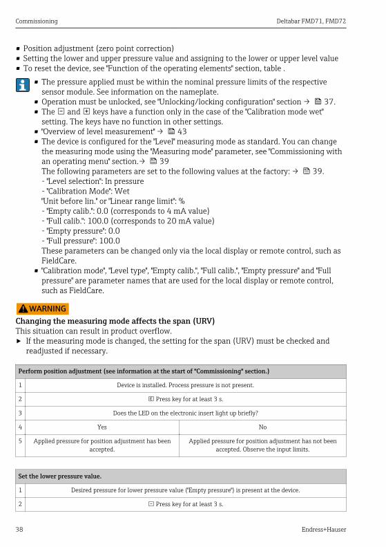
• Position adjustment (zero point correction)• Setting the lower and upper pressure value and assigning to the lower or upper level value• To reset the device, see "Function of the operating elements" section, table .
• The pressure applied must be within the nominal pressure limits of the respectivesensor module. See information on the nameplate.
• Operation must be unlocked, see "Unlocking/locking configuration" section → 37.• The and keys have a function only in the case of the "Calibration mode wet"
setting. The keys have no function in other settings.• "Overview of level measurement" → 43• The device is configured for the "Level" measuring mode as standard. You can change
the measuring mode using the "Measuring mode" parameter, see "Commissioning withan operating menu" section.→ 39The following parameters are set to the following values at the factory: → 39.- "Level selection": In pressure- "Calibration Mode": Wet"Unit before lin." or "Linear range limit": %- "Empty calib.": 0.0 (corresponds to 4 mA value)- "Full calib.": 100.0 (corresponds to 20 mA value)- "Empty pressure": 0.0- "Full pressure": 100.0These parameters can be changed only via the local display or remote control, such asFieldCare.
• "Calibration mode", "Level type", "Empty calib.", "Full calib.", "Empty pressure" and "Fullpressure" are parameter names that are used for the local display or remote control,such as FieldCare.
LWARNINGChanging the measuring mode affects the span (URV)This situation can result in product overflow.‣ If the measuring mode is changed, the setting for the span (URV) must be checked and
readjusted if necessary.
Perform position adjustment (see information at the start of "Commissioning" section.)
1 Device is installed. Process pressure is not present.
2 Press key for at least 3 s.
3 Does the LED on the electronic insert light up briefly?
4 Yes No
5 Applied pressure for position adjustment has beenaccepted.
Applied pressure for position adjustment has not beenaccepted. Observe the input limits.
Set the lower pressure value.
1 Desired pressure for lower pressure value ("Empty pressure") is present at the device.
2 Press key for at least 3 s.
Deltabar FMD71, FMD72 Commissioning
Endress+Hauser 39
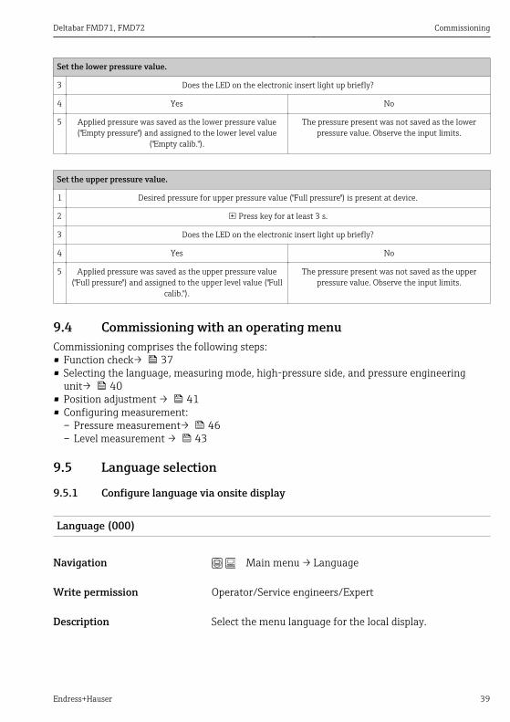
Set the lower pressure value.
3 Does the LED on the electronic insert light up briefly?
4 Yes No
5 Applied pressure was saved as the lower pressure value("Empty pressure") and assigned to the lower level value
("Empty calib.").
The pressure present was not saved as the lowerpressure value. Observe the input limits.
Set the upper pressure value.
1 Desired pressure for upper pressure value ("Full pressure") is present at device.
2 Press key for at least 3 s.
3 Does the LED on the electronic insert light up briefly?
4 Yes No
5 Applied pressure was saved as the upper pressure value("Full pressure") and assigned to the upper level value ("Full
calib.").
The pressure present was not saved as the upperpressure value. Observe the input limits.
9.4 Commissioning with an operating menuCommissioning comprises the following steps:• Function check→ 37• Selecting the language, measuring mode, high-pressure side, and pressure engineering
unit→ 40• Position adjustment → 41• Configuring measurement:
– Pressure measurement→ 46– Level measurement → 43
9.5 Language selection
9.5.1 Configure language via onsite display
Language (000)
Navigation Main menu → Language
Write permission Operator/Service engineers/Expert
Description Select the menu language for the local display.
Commissioning Deltabar FMD71, FMD72
40 Endress+Hauser
Options • English• Another language (as selected when ordering the device)• Possibly a third language (language of the manufacturing
plant)
Factory setting English
9.5.2 Configuring language via operating tool (FieldCare)See Operating Instructions.
9.6 Measuring mode selectionLWARNING
Changing the measuring mode affects the span (URV)This situation can result in product overflow.‣ If the measuring mode is changed, the setting for the span (URV) must be checked in the
"Setup" operating menu and readjusted if necessary.
Measuring mode (005)
Navigation Setup → Measuring mode
Write permission Operator/Service engineers/Expert
Description Select the measuring mode.The operating menu is structured differently depending onthe measuring mode selected.
Options • Pressure• Level
Factory setting Level
9.7 Selecting the high-pressure side
9.7.1 Defining the high-pressure side
High press. side (183)
Navigation Setup → High press. side
Deltabar FMD71, FMD72 Commissioning
Endress+Hauser 41
Write permission Operator/Service engineers/Expert
Description Define which sensor module corresponds to the high-pressure side.
Options • Sensor module HP• Sensor module LP
Factory setting Sensor module HP
9.8 Pressure unit selection
Press. eng. unit (125)
Navigation Setup → Press. eng. unit
Write permission Operators/Service engineers/Expert
Description Select the pressure engineering unit. If a new pressureengineering unit is selected, all pressure-specificparameters are converted and displayed with the new unit.
Options • mbar, bar• mmH2O, mH2O• in H2O, ftH2O• Pa, kPa, MPa• psi• mmHg, inHg• kgf/cm2
Factory setting mbar, bar or psi depending on the sensor module nominalmeasuring range, or as per order specifications.
9.9 Pos. zero adjustThe pressure resulting from the orientation of the device can be corrected here.
Corrected press. (172)
Navigation Setup → Corrected press.
Commissioning Deltabar FMD71, FMD72
42 Endress+Hauser
Write permission Operators/Service engineers/Expert
Description Displays the measured pressure after the differentialpressure buildup and position adjustment.
Note If this value is not equal to "0", it can be corrected to "0" bythe position adjustment.
Pos. zero adjust (007)
Navigation Setup → Pos. zero adjust
Write permission Operators/Service engineers/Expert
Description Position adjustment – the pressure difference between zero(set point) and the measured differential pressure need notbe known.
Options • Confirm• Cancel
Example • Measured value = 2.2 mbar (0.033 psi)• You correct the measured value via the "Pos. zero adjust"
parameter with the "Confirm" option. This means that youare assigning the value 0.0 to the pressure present.
• Measured value (after pos. zero adjust) = 0.0 mbar• The current value is also corrected.
Factory setting Cancel
Deltabar FMD71, FMD72 Commissioning
Endress+Hauser 43
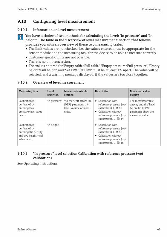
9.10 Configuring level measurement
9.10.1 Information on level measurementYou have a choice of two methods for calculating the level: "In pressure" and "Inheight". The table in the "Overview of level measurement" section that followsprovides you with an overview of these two measuring tasks.• The limit values are not checked, i.e. the values entered must be appropriate for the
sensor module and the measuring task for the device to be able to measure correctly.• Customer-specific units are not possible.• There is no unit conversion.• The values entered for "Empty calib./Full calib.", "Empty pressure/Full pressure", "Empty
height/Full height" and "Set LRV/Set URV" must be at least 1% apart. The value will berejected, and a warning message displayed, if the values are too close together.
9.10.2 Overview of level measurement
Measuring task Levelselection
Measured variableoptions
Description Measured valuedisplay
Calibration isperformed byentering twopressure-level valuepairs.
"In pressure" Via the "Unit before lin.(025)" parameter : %,level, volume or massunits.
• Calibration withreference pressure (wetcalibration)→ 43
• Calibration withoutreference pressure (drycalibration), → 44
The measured valuedisplay and the "Levelbefore lin (019)"parameter show themeasured value.
Calibration isperformed byentering the densityand two height-levelvalue pairs.
"In height" • Calibration withreference pressure (wetcalibration)→ 46
• Calibration withoutreference pressure (drycalibration), → 46
9.10.3 "In pressure" level selection Calibration with reference pressure (wetcalibration)
See Operating Instructions.
Commissioning Deltabar FMD71, FMD72
44 Endress+Hauser
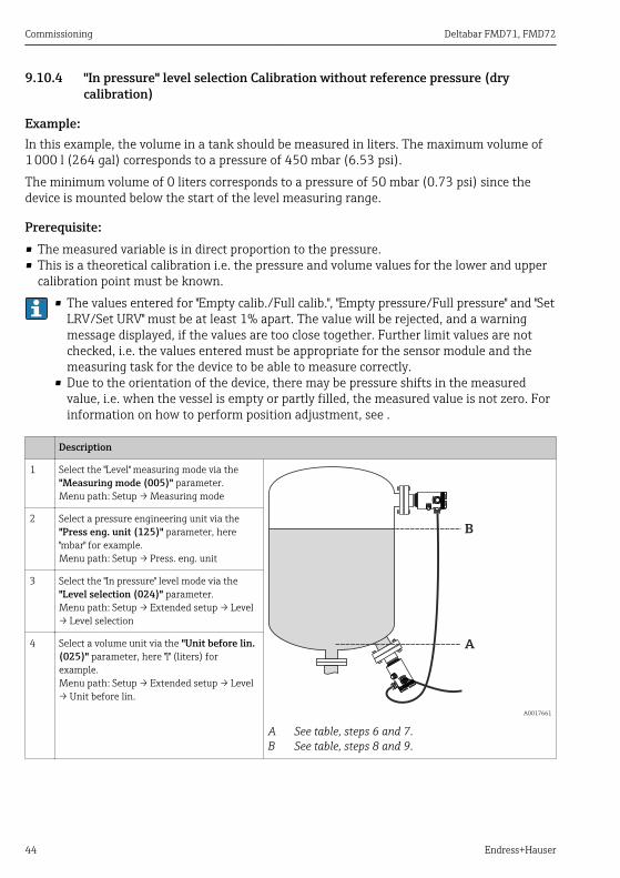
9.10.4 "In pressure" level selection Calibration without reference pressure (drycalibration)
Example:In this example, the volume in a tank should be measured in liters. The maximum volume of1 000 l (264 gal) corresponds to a pressure of 450 mbar (6.53 psi).The minimum volume of 0 liters corresponds to a pressure of 50 mbar (0.73 psi) since thedevice is mounted below the start of the level measuring range.
Prerequisite:• The measured variable is in direct proportion to the pressure.• This is a theoretical calibration i.e. the pressure and volume values for the lower and upper
calibration point must be known.• The values entered for "Empty calib./Full calib.", "Empty pressure/Full pressure" and "Set
LRV/Set URV" must be at least 1% apart. The value will be rejected, and a warningmessage displayed, if the values are too close together. Further limit values are notchecked, i.e. the values entered must be appropriate for the sensor module and themeasuring task for the device to be able to measure correctly.
• Due to the orientation of the device, there may be pressure shifts in the measuredvalue, i.e. when the vessel is empty or partly filled, the measured value is not zero. Forinformation on how to perform position adjustment, see .
Description
1 Select the "Level" measuring mode via the"Measuring mode (005)" parameter.Menu path: Setup → Measuring mode
A
B
A0017661
A See table, steps 6 and 7.B See table, steps 8 and 9.
2 Select a pressure engineering unit via the"Press eng. unit (125)" parameter, here"mbar" for example.Menu path: Setup → Press. eng. unit
3 Select the "In pressure" level mode via the"Level selection (024)" parameter.Menu path: Setup → Extended setup → Level→ Level selection
4 Select a volume unit via the "Unit before lin.(025)" parameter, here "l" (liters) forexample.Menu path: Setup → Extended setup → Level→ Unit before lin.
Deltabar FMD71, FMD72 Commissioning
Endress+Hauser 45
Description
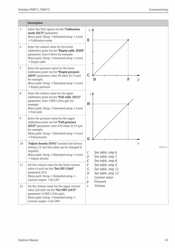
5 Select the "Dry" option via the "Calibrationmode (027)" parameter.Menu path: Setup → Extended setup → Level→ Calibration mode
C
D
E
F
G
H
v
p
i
v A0034736
C See table, step 6.D See table, step 7.E See table, step 8.F See table, step 9.G See table, step 11H See table, step 12i Current valuep Pressurev Volume
6 Enter the volume value for the lowercalibration point via the "Empty calib. (028)"parameter, here 0 liters for example.Menu path: Setup → Extended setup → Level→ Empty calib.
7 Enter the pressure value for the lowercalibration point via the "Empty pressure(029)" parameter, here 50 mbar (0.73 psi)for example.Menu path: Setup → Extended setup → Level→ Empty pressure
8 Enter the volume value for the uppercalibration point via the "Full calib. (031)"parameter, here 1 000 l (264 gal) forexample.Menu path: Setup → Extended setup → Level→ Full calib.
9 Enter the pressure value for the uppercalibration point via the "Full pressure(032)" parameter, here 450 mbar (6.53 psi)for example.Menu path: Setup → Extended setup → Level→ Full pressure
10 "Adjust density (034)" contains the factorysetting 1.0, but this value can be changed ifrequired.Menu path: Setup → Extended setup → Level→ Adjust density
11 Set the volume value for the lower currentvalue (4 mA) via the "Set LRV (166)"parameter (0 l).Menu path: Setup → Extended setup →Current output → Set LRV
12 Set the volume value for the upper currentvalue (20 mA) via the "Set URV (167)"parameter (1 000 l (264 gal)).Menu path: Setup → Extended setup →Current output → Set URV
Commissioning Deltabar FMD71, FMD72
46 Endress+Hauser
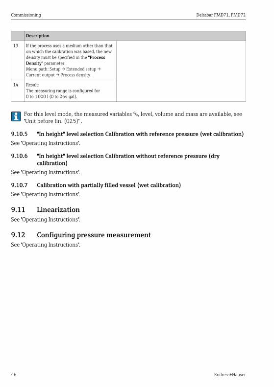
Description
13 If the process uses a medium other than thaton which the calibration was based, the newdensity must be specified in the "ProcessDensity" parameter.Menu path: Setup → Extended setup →Current output → Process density.
14 Result:The measuring range is configured for0 to 1 000 l (0 to 264 gal).
For this level mode, the measured variables %, level, volume and mass are available, see"Unit before lin. (025)" .
9.10.5 "In height" level selection Calibration with reference pressure (wet calibration)See "Operating Instructions".
9.10.6 "In height" level selection Calibration without reference pressure (drycalibration)
See "Operating Instructions".
9.10.7 Calibration with partially filled vessel (wet calibration)See "Operating Instructions".
9.11 LinearizationSee "Operating Instructions".
9.12 Configuring pressure measurementSee "Operating Instructions".


www.addresses.endress.com
*71376030*71376030