Embed Size (px)
Citation preview

Dell™ Networking™ X1000 and X4000 Series SwitchesUser Guide
FILE LOCATION: C:\Users\vijaya_devakumar_dev\Documents\PowerConnect\Astute\Docs for Web Posting\Astute_Admin_Guide_sources_MIF7\FM\Dell_AstuteCover.fmD E L L C O N F I D E N T I A L – P R E L I M I N A R Y 3 / 1 9 / 1 5 – F O R P R O O F O N LY
Template Last Updated -03/06/2010

FILE LOCATION: C:\Users\vijaya_devakumar_dev\Documents\PowerConnect\Astute\Docs for Web
Notes, Cautions, and Warnings NOTE: A NOTE indicates important information that helps you make better use of
your computer.
CAUTION: A CAUTION indicates either potential damage to hardware, or loss of data and tells you how to avoid the problem.
WARNING: A WARNING indicates a potential for property damage, personal injury, or death.
____________________
© Copyright © 2015 Dell Inc. All rights reserved. This product is protected by U.S. and international copyright and intellectual property laws. Dell and the Dell logo are trademarks of Dell Inc. in the United States and/or other jurisdictions. All other marks and names mentioned herein may be trademarks of their respective companies.
February 2015 Rev. A00
DELL CONFIDENTIAL – PRELIMINARY 3/19/15 – FOR PROOF ONLY

FILE LOCATION: C:\Users\vijaya_devakumar_dev\Documents\PowerConnect\Astute\Docs for Web
Posting\Astute_Admin_Guide_sources_MIF7\FM\Dell_AstuteUG_PrintTOC.fm
Table of Contents
Table of Contents . . . . . . . . . . . . . . . . . . . . . . . . 3
1 Preface . . . . . . . . . . . . . . . . . . . . . . . . . . 13
2 Features . . . . . . . . . . . . . . . . . . . . . . . . . . 15
MAC Address Capacity Support . . . . . . . . . . . . . 17
Layer 2 Features . . . . . . . . . . . . . . . . . . . . . 18
VLAN Supported Features . . . . . . . . . . . . . . . . 19
Spanning Tree Protocol Features . . . . . . . . . . . . 21
Quality of Service Features . . . . . . . . . . . . . . . 23
Device Management Features. . . . . . . . . . . . . . 24
Security Features . . . . . . . . . . . . . . . . . . . . 27
3 Hardware Description . . . . . . . . . . . . . . . 33
Device Models . . . . . . . . . . . . . . . . . . . . . . 34
Device Structure . . . . . . . . . . . . . . . . . . . . . 35
Managed Mode Button . . . . . . . . . . . . . . . . . 36
Reset Button . . . . . . . . . . . . . . . . . . . . . . . 36
Fans . . . . . . . . . . . . . . . . . . . . . . . . . . . 37
LED Definitions. . . . . . . . . . . . . . . . . . . . . . 37
Power Supplies . . . . . . . . . . . . . . . . . . . . . 39
Contents 3

FILE LOCATION: C:\Users\vijaya_devakumar_dev\Documents\PowerConnect\Astute\Docs for Web
Posting\Astute_Admin_Guide_sources_MIF7\FM\Dell_AstuteUG_PrintTOC.fm
4 Using the GUI . . . . . . . . . . . . . . . . . . . . . 43
Starting the Application . . . . . . . . . . . . . . . . . 44
Understanding the Interface . . . . . . . . . . . . . . . 44
Dashboard . . . . . . . . . . . . . . . . . . . . . . . . 45
Saving Configurations . . . . . . . . . . . . . . . . . . 45
Information Buttons . . . . . . . . . . . . . . . . . . . 46
Field Definitions . . . . . . . . . . . . . . . . . . . . . 47
Common GUI Features . . . . . . . . . . . . . . . . . . 48
. . . . . . . . . . . . . . . . . . . . . . . . . . . . . . 48
5 Dashboard . . . . . . . . . . . . . . . . . . . . . . . 49
Overview . . . . . . . . . . . . . . . . . . . . . . . . . 50
Interfaces. . . . . . . . . . . . . . . . . . . . . . . . . 51
Switch Information. . . . . . . . . . . . . . . . . . . . 53
Resources . . . . . . . . . . . . . . . . . . . . . . . . 55
Recent Logged Events . . . . . . . . . . . . . . . . . . 57
Active Alerts . . . . . . . . . . . . . . . . . . . . . . . 58
Ports and VLANs . . . . . . . . . . . . . . . . . . . . . 59
Configuration Wizards . . . . . . . . . . . . . . . . . . 60
6 Switch Management . . . . . . . . . . . . . . . 71
IP Addressing Overview . . . . . . . . . . . . . . . . . 71
Switch Information. . . . . . . . . . . . . . . . . . . . 72
4 Contents

FILE LOCATION: C:\Users\vijaya_devakumar_dev\Documents\PowerConnect\Astute\Docs for Web
Posting\Astute_Admin_Guide_sources_MIF7\FM\Dell_AstuteUG_PrintTOC.fm
IPv4 Addressing . . . . . . . . . . . . . . . . . . . . . 73
IPv6 Addressing . . . . . . . . . . . . . . . . . . . . . 75
File Update and Backup . . . . . . . . . . . . . . . . . 83
Domain Name System (DNS) . . . . . . . . . . . . . . 92
Time Synchronization . . . . . . . . . . . . . . . . . . 95
Management Security . . . . . . . . . . . . . . . . . . 104
7 Logs and Alerts . . . . . . . . . . . . . . . . . . . 119
Overview . . . . . . . . . . . . . . . . . . . . . . . . . 119
Logs . . . . . . . . . . . . . . . . . . . . . . . . . . . 120
Login History . . . . . . . . . . . . . . . . . . . . . . . 121
Remote Log Servers . . . . . . . . . . . . . . . . . . . 121
8 Statistics and Diagnostics . . . . . . . . . . 123
Monitoring . . . . . . . . . . . . . . . . . . . . . . . . 123
Statistics . . . . . . . . . . . . . . . . . . . . . . . . . 129
Diagnostics . . . . . . . . . . . . . . . . . . . . . . . 134
9 Network Administration: VLAN . . . . . . . 137
VLAN Overview . . . . . . . . . . . . . . . . . . . . . 137
Standard VLAN. . . . . . . . . . . . . . . . . . . . . . 141
Voice VLAN . . . . . . . . . . . . . . . . . . . . . . . 150
Contents 5

FILE LOCATION: C:\Users\vijaya_devakumar_dev\Documents\PowerConnect\Astute\Docs for Web
Posting\Astute_Admin_Guide_sources_MIF7\FM\Dell_AstuteUG_PrintTOC.fm
10 Network Administration: Port Settings . 155
Ports . . . . . . . . . . . . . . . . . . . . . . . . . . 155
Address Tables . . . . . . . . . . . . . . . . . . . . . 167
UDLD . . . . . . . . . . . . . . . . . . . . . . . . . . 169
11 Network Administration: Spanning Tree and LAG
179
Spanning Tree . . . . . . . . . . . . . . . . . . . . . 179
Link Aggregation (LAG) . . . . . . . . . . . . . . . . 190
12 Network Administration: Link Layer Discovery Protocol (LLDP) . . . . . . . . . . . . . . . . . . 201
Overview . . . . . . . . . . . . . . . . . . . . . . . . 201
LLDP Properties . . . . . . . . . . . . . . . . . . . . 202
LLDP Port Settings . . . . . . . . . . . . . . . . . . . 203
MED Network Policy . . . . . . . . . . . . . . . . . 204
MED Port Settings . . . . . . . . . . . . . . . . . . . 205
Neighbors Information . . . . . . . . . . . . . . . . . 207
13 Network Administration: Route Settings 209
System Routing Mode . . . . . . . . . . . . . . . . . 209
IPv4 Route Settings . . . . . . . . . . . . . . . . . . 209
IPv6 Route Settings . . . . . . . . . . . . . . . . . . 214
6 Contents

FILE LOCATION: C:\Users\vijaya_devakumar_dev\Documents\PowerConnect\Astute\Docs for Web
Posting\Astute_Admin_Guide_sources_MIF7\FM\Dell_AstuteUG_PrintTOC.fm
14 Network Administration: Quality of Service 221
Overview . . . . . . . . . . . . . . . . . . . . . . . . . 221
Global Settings. . . . . . . . . . . . . . . . . . . . . . 222
QoS Mapping. . . . . . . . . . . . . . . . . . . . . . . 227
QoS Statistics . . . . . . . . . . . . . . . . . . . . . . 236
15 Network Administration: Security . . . . . 239
Dot1x Authentications . . . . . . . . . . . . . . . . . . 239
Storm Control Configuration . . . . . . . . . . . . . . . 249
Port Security . . . . . . . . . . . . . . . . . . . . . . . 250
Dynamic ARP Inspection (DAI) . . . . . . . . . . . . . 252
ACL and ACE . . . . . . . . . . . . . . . . . . . . . . . 255
16 Network Administration: SNMP Monitoring 271
SNMP Overview . . . . . . . . . . . . . . . . . . . . . 271
SNMP Global Parameters . . . . . . . . . . . . . . . . 273
View Settings . . . . . . . . . . . . . . . . . . . . . . 275
Access Control . . . . . . . . . . . . . . . . . . . . . 276
User Security Model . . . . . . . . . . . . . . . . . . 277
Communities . . . . . . . . . . . . . . . . . . . . . . . 278
Notification Filter . . . . . . . . . . . . . . . . . . . . 280
Notification Recipients . . . . . . . . . . . . . . . . . 281
Contents 7

FILE LOCATION: C:\Users\vijaya_devakumar_dev\Documents\PowerConnect\Astute\Docs for Web
Posting\Astute_Admin_Guide_sources_MIF7\FM\Dell_AstuteUG_PrintTOC.fm
17 Network Administration: Multicast . . . . 283
Overview . . . . . . . . . . . . . . . . . . . . . . . . 283
Global Parameters . . . . . . . . . . . . . . . . . . . 285
Multicast Group . . . . . . . . . . . . . . . . . . . . 286
Multicast Forward All . . . . . . . . . . . . . . . . . 287
IGMP Snooping. . . . . . . . . . . . . . . . . . . . . 288
MLD Snooping . . . . . . . . . . . . . . . . . . . . . 291
Unregistered Multicast . . . . . . . . . . . . . . . . 292
Multicast TV VLAN . . . . . . . . . . . . . . . . . . . 293
18 Network Administration: DHCP Snooping and DHCP Relay . . . . . . . . . . . . . . . . . . . . . . 295
DHCP Snooping . . . . . . . . . . . . . . . . . . . . 295
DHCP Relay. . . . . . . . . . . . . . . . . . . . . . . 300
19 Network Administration: DHCP Server . 303
Overview . . . . . . . . . . . . . . . . . . . . . . . . 303
DHCP Server Properties . . . . . . . . . . . . . . . . 304
Network Pool. . . . . . . . . . . . . . . . . . . . . . 305
Static Hosts. . . . . . . . . . . . . . . . . . . . . . . 307
Address Binding . . . . . . . . . . . . . . . . . . . . 309
Excluded Addresses . . . . . . . . . . . . . . . . . . 310
8 Contents

FILE LOCATION: C:\Users\vijaya_devakumar_dev\Documents\PowerConnect\Astute\Docs for Web
Posting\Astute_Admin_Guide_sources_MIF7\FM\Dell_AstuteUG_PrintTOC.fm
20 Network Administration: Power Management 311
Green Ethernet . . . . . . . . . . . . . . . . . . . . . . 311
Power Over Ethernet (PoE) . . . . . . . . . . . . . . . 314
21 Network Administration: sFlow . . . . . . . 317
22 Using the CLI . . . . . . . . . . . . . . . . . . . . . 321
Using the CLI . . . . . . . . . . . . . . . . . . . . . . . 321
CLI Command Conventions . . . . . . . . . . . . . . . 324
Accessing the Device Through the CLI . . . . . . . . . 325
IPv6 Address Conventions . . . . . . . . . . . . . . . . 325
23 CLI . . . . . . . . . . . . . . . . . . . . . . . . . . . . . 327
clear counters . . . . . . . . . . . . . . . . . . . . . . . . . . . . . . . . . . . . . 327
clear logging . . . . . . . . . . . . . . . . . . . . . . . . . . . . . . . . . . . . . . 327
configure . . . . . . . . . . . . . . . . . . . . . . . . . . . . . . . . . . . . . . . . . 328
copy . . . . . . . . . . . . . . . . . . . . . . . . . . . . . . . . . . . . . . . . . . . . . . 328
crypto certificate generate . . . . . . . . . . . . . . . . . . . . . . . . . . 332
crypto certificate import . . . . . . . . . . . . . . . . . . . . . . . . . . . . 334
crypto certificate request . . . . . . . . . . . . . . . . . . . . . . . . . . . 337
crypto key generate dsa . . . . . . . . . . . . . . . . . . . . . . . . . . . . 339
crypto key generate rsa . . . . . . . . . . . . . . . . . . . . . . . . . . . . . 341
crypto key import . . . . . . . . . . . . . . . . . . . . . . . . . . . . . . . . . . 342
debug-mode . . . . . . . . . . . . . . . . . . . . . . . . . . . . . . . . . . . . . . . 343
delete . . . . . . . . . . . . . . . . . . . . . . . . . . . . . . . . . . . . . . . . . . . . 344
dir . . . . . . . . . . . . . . . . . . . . . . . . . . . . . . . . . . . . . . . . . . . . . . . . 345
Contents 9

FILE LOCATION: C:\Users\vijaya_devakumar_dev\Documents\PowerConnect\Astute\Docs for Web
Posting\Astute_Admin_Guide_sources_MIF7\FM\Dell_AstuteUG_PrintTOC.fm
do. . . . . . . . . . . . . . . . . . . . . . . . . . . . . . . . . . . . . . . . . . . . . . . . 346
enable. . . . . . . . . . . . . . . . . . . . . . . . . . . . . . . . . . . . . . . . . . . . 347
end . . . . . . . . . . . . . . . . . . . . . . . . . . . . . . . . . . . . . . . . . . . . . . 348
exit (EXEC) . . . . . . . . . . . . . . . . . . . . . . . . . . . . . . . . . . . . . . . . 348
exit (Configuration) . . . . . . . . . . . . . . . . . . . . . . . . . . . . . . . . 349
help . . . . . . . . . . . . . . . . . . . . . . . . . . . . . . . . . . . . . . . . . . . . . . 349
interface. . . . . . . . . . . . . . . . . . . . . . . . . . . . . . . . . . . . . . . . . . 350
ip address . . . . . . . . . . . . . . . . . . . . . . . . . . . . . . . . . . . . . . . . 351
ip default-gateway. . . . . . . . . . . . . . . . . . . . . . . . . . . . . . . . . 353
ip https certificate . . . . . . . . . . . . . . . . . . . . . . . . . . . . . . . . . 354
ip routing . . . . . . . . . . . . . . . . . . . . . . . . . . . . . . . . . . . . . . . . . 354
ip ssh server . . . . . . . . . . . . . . . . . . . . . . . . . . . . . . . . . . . . . . 355
lldp transmit . . . . . . . . . . . . . . . . . . . . . . . . . . . . . . . . . . . . . . 356
lldp receive . . . . . . . . . . . . . . . . . . . . . . . . . . . . . . . . . . . . . . 357
login . . . . . . . . . . . . . . . . . . . . . . . . . . . . . . . . . . . . . . . . . . . . . 358
ping . . . . . . . . . . . . . . . . . . . . . . . . . . . . . . . . . . . . . . . . . . . . . . 359
power inline legacy support disable . . . . . . . . . . . . . . . . . 362
power inline usage-threshold . . . . . . . . . . . . . . . . . . . . . . . 363
reload . . . . . . . . . . . . . . . . . . . . . . . . . . . . . . . . . . . . . . . . . . . . 363
show bootvar . . . . . . . . . . . . . . . . . . . . . . . . . . . . . . . . . . . . . 365
show crypto certificate. . . . . . . . . . . . . . . . . . . . . . . . . . . . . 366
show crypto key . . . . . . . . . . . . . . . . . . . . . . . . . . . . . . . . . . . 367
show interfaces counters. . . . . . . . . . . . . . . . . . . . . . . . . . . 369
show interfaces status . . . . . . . . . . . . . . . . . . . . . . . . . . . . . 371
show ip dhcp tftp-server. . . . . . . . . . . . . . . . . . . . . . . . . . . . 372
show ip https. . . . . . . . . . . . . . . . . . . . . . . . . . . . . . . . . . . . . . 373
show ip interface . . . . . . . . . . . . . . . . . . . . . . . . . . . . . . . . . . 374
10 Contents

FILE LOCATION: C:\Users\vijaya_devakumar_dev\Documents\PowerConnect\Astute\Docs for Web
Posting\Astute_Admin_Guide_sources_MIF7\FM\Dell_AstuteUG_PrintTOC.fm
show power inline . . . . . . . . . . . . . . . . . . . . . . . . . . . . . . . . . 375
show power inline consumption . . . . . . . . . . . . . . . . . . . . . 378
show running-config . . . . . . . . . . . . . . . . . . . . . . . . . . . . . . . 379
show system . . . . . . . . . . . . . . . . . . . . . . . . . . . . . . . . . . . . . . 380
show tech-support . . . . . . . . . . . . . . . . . . . . . . . . . . . . . . . . . 381
show version . . . . . . . . . . . . . . . . . . . . . . . . . . . . . . . . . . . . . . 382
show vlan . . . . . . . . . . . . . . . . . . . . . . . . . . . . . . . . . . . . . . . . . 383
spanning-tree . . . . . . . . . . . . . . . . . . . . . . . . . . . . . . . . . . . . . 385
username . . . . . . . . . . . . . . . . . . . . . . . . . . . . . . . . . . . . . . . . . 385
vlan . . . . . . . . . . . . . . . . . . . . . . . . . . . . . . . . . . . . . . . . . . . . . . 386
write . . . . . . . . . . . . . . . . . . . . . . . . . . . . . . . . . . . . . . . . . . . . . 388
24 Getting Help . . . . . . . . . . . . . . . . . . . . . . 389
Contacting Dell . . . . . . . . . . . . . . . . . . . . . 389
Locating Your System Service Tag . . . . . . . . . . . 389
Downloading Drivers, Firmware, and Software . . . . 390
Related Documentation . . . . . . . . . . . . . . . . . 390
Documentation Feedback . . . . . . . . . . . . . . . . 390
Glossary . . . . . . . . . . . . . . . . . . . . . . . . . . . . 391
Contents 11

FILE LOCATION: C:\Users\vijaya_devakumar_dev\Documents\PowerConnect\Astute\Docs for Web
Posting\Astute_Admin_Guide_sources_MIF7\FM\Dell_AstuteUG_PrintTOC.fm
12 Contents

D E L L C O N F I D E N T I A L – P R E L I M I N A RY 3 / 1 9 / 1 5 - F O R P R O O F O N LY
1PrefaceThis guide contains the information needed for configuring and maintaining the Dell™ Networking™ X1000 and X4000 Series devices through the Dell Networking Administrator.
For explanation of acronyms, refer to the Glossary.
Template Last Updated - 2010 Preface 13

FILE LOCATION: C:\Users\vijaya_devakumar_dev\Documents\PowerConnect\Astute\Docs for Web Posting\Astute_Admin_Guide_sources_MIF7\FM\Dell_Astute_Prefix.fm
D E L L C O N F I D E N T I A L – P R E L I M I N A R Y 3 / 1 9 / 1 5 - F O R P R O O F O N LY
14 Preface

D E L L C O N F I D E N T I A L – P R E L I M I N A RY 3 / 1 9 / 1 5 - F O R P R O O F O N LY
2FeaturesThis section describes the features of the Dell™ Networking™ X1000 and X4000 Series devices.
For a complete list of all updated device features, see the Release Notes included in the latest version of software released at dell.com/support.
This section provides a brief description of the following features:
• IP Version 6 (IPv6) Support
• Head of Line Blocking Prevention
• Back Pressure Support
• Virtual Cable Testing (VCT)
• Auto-Negotiation
• MDI/MDIX Support
• MAC Address Capacity Support
• Layer 2 Features
• IGMP Snooping
• MLD Snooping
• Port and VLAN Mirroring
• Broadcast Storm Control
• VLAN Support
• Spanning Tree Protocol Features
• Link Aggregation
• Quality of Service Features
• Device Management Features
• Security Features
• DHCP Server
• Protected Ports
• Proprietary Protocol Filtering
Template Last Updated - 2010 Features 15

FILE LOCATION: C:\Users\vijaya_devakumar_dev\Documents\PowerConnect\Astute\Docs for Web Posting\Astute_Admin_Guide_sources_MIF7\FM\Dell_Astute_Features.fm
D E L L C O N F I D E N T I A L – P R E L I M I N A R Y 3 / 1 9 / 1 5 - F O R P R O O F O N LY
• UDLD
• Static Routing
• IPv6 Router
• sFlow
IP Version 6 (IPv6) SupportThe device functions as an IPv6-compliant host, as well as an IPv4 host (also known as dual stack). This enables device operation in a pure IPv6 network as well as in a combined IPv4/IPv6 network.
For more information, see IPv6 Addressing.
Head of Line Blocking PreventionHead of Line (HOL) blocking results in traffic delays and frame loss caused by traffic competing for the same egress port resources. The switch prevents HOL blocking by queueing packets, such that packets in the front of a queue do not block the packets behind if they are to be sent to different ports.
Back Pressure SupportOn half-duplex links, the receiving port prevents buffer overflows by occupying the link so that it is unavailable for additional traffic.
For more information, see Back Pressure.
Virtual Cable Testing (VCT)VCT detects and reports copper link cabling faults, such as open cables and cable shorts.
For more information, see Diagnostics.
Auto-NegotiationAuto-negotiation enables the device to advertise modes of operation. The auto-negotiation function enables an exchange of information between two devices that share a point-to-point link segment, and automatically configures both devices to take maximum advantage of their transmission capabilities.
16 Features

FILE LOCATION: C:\Users\vijaya_devakumar_dev\Documents\PowerConnect\Astute\Docs for Web Posting\Astute_Admin_Guide_sources_MIF7\FM\Dell_Astute_Features.fm
D E L L C O N F I D E N T I A L – P R E L I M I N A RY 3 / 1 9 / 1 5 - F O R P R O O F O N LY
The devices enhance auto-negotiation by providing port advertisement. Port advertisement enables the system administrator to configure the port speeds that are advertised.
For more information, see Network Administration: Port Settings.
MDI/MDIX SupportStandard wiring for end stations is known as Media-Dependent Interface (MDI), and standard wiring for hubs and switches is known as Media-Dependent Interface with Crossover (MDIX).
If auto-negotiation is enabled, the device automatically detects whether the cable connected to an RJ-45 port is MDIX (crossed) or MDI (straight). This enables both types to be used interchangeably.
If auto-negotiation is disabled, only MDI (straight) cables can be used.
For more information, see MDI/MDIX.
MAC Address Capacity Support
MAC Address Capacity SupportAll SKUs support up to 16K MAC addresses except for the X4012 that supports 32K addresses. They reserve specific MAC addresses for system use.
For more information, see Address Tables.
Static MAC EntriesMAC entries can be manually entered in the Bridging Table, as an alternative to learning them from incoming frames. These user-defined entries are not subject to aging and are preserved across reset to reboots.
For more information, see Address Tables.
Self-Learning MAC AddressesThe device enables controlled MAC address learning from incoming packets. The MAC addresses are stored in the Dynamic Address Table.
For more information, see Address Tables.
Features 17

FILE LOCATION: C:\Users\vijaya_devakumar_dev\Documents\PowerConnect\Astute\Docs for Web Posting\Astute_Admin_Guide_sources_MIF7\FM\Dell_Astute_Features.fm
D E L L C O N F I D E N T I A L – P R E L I M I N A R Y 3 / 1 9 / 1 5 - F O R P R O O F O N LY
Automatic Aging for MAC AddressesMAC addresses from which no traffic is received for a given period, are aged out. This frees Bridging Table resources for learning new MAC addresses.
For more information, see Address Tables.
VLAN-Aware MAC-Based SwitchingThe device always performs VLAN-aware bridging. VLAN-aware bridges perform VLAN-based MAC address learning and forwarding. Frames addressed to a unknown destination MAC address are flooded to all ports of the relevant VLAN.
This is a standard feature.
MAC Multicast SupportMulticast service is a service that enables one-to-many and many-to-many communication for information distribution. In Layer 2 Multicast service, a single frame is addressed to a specific Multicast address, from which copies of the frame are transmitted to the relevant ports. When Multicast groups are statically enabled, you can set the destination port of registered groups, as well as define the behavior of unregistered Multicast frames.
For more information, see Network Administration: Multicast.
Layer 2 Features
IGMP SnoopingInternet Group Management Protocol (IGMP) Snooping examines IGMP frame contents, when they are forwarded by the device from work stations to an upstream Multicast router. From the frame data, the device identifies work stations configured for Multicast sessions, and which Multicast routers are sending Multicast frames. The IGMP Querier simulates the behavior of a Multicast router. This enables snooping of the Layer 2 Multicast domain even if there is no Multicast router.
For more information, see IGMP Snooping.
18 Features

FILE LOCATION: C:\Users\vijaya_devakumar_dev\Documents\PowerConnect\Astute\Docs for Web Posting\Astute_Admin_Guide_sources_MIF7\FM\Dell_Astute_Features.fm
D E L L C O N F I D E N T I A L – P R E L I M I N A RY 3 / 1 9 / 1 5 - F O R P R O O F O N LY
MLD SnoopingMulticast Listener Discovery (MLD) Snooping performs the function of IGMP Snooping for IPv6.
For more information, see MLD Snooping.
Port and VLAN MirroringPort and VLAN mirroring monitors network traffic by forwarding copies of incoming and outgoing packets from a monitored port to a monitoring port. Users specify which target port receives copies of all traffic passing through a specified source port.
For more information, see Port and VLAN Mirrorings.
Broadcast Storm ControlStorm Control limits the number of Multicast and Broadcast frames accepted and forwarded by the device.
When Layer 2 frames are forwarded, Broadcast and Multicast frames are forwarded to multiple ports on the relevant VLAN and excess Broadcast and Multicast could degrade network performance and disrupt services.
For more information, see Storm Control Configuration.
VLAN Supported Features
VLAN SupportVLANs are collections of switching ports that comprise a single Broadcast domain. Packets are classified as belonging to a VLAN, based on either the VLAN tag or on a combination of the ingress port and packet contents. Packets sharing common attributes can be grouped in the same VLAN.
For more information, see VLAN Membership.
Port-Based Virtual LANs (VLANs)Port-based VLANs classify incoming packets to VLANs, based on their ingress port.
For more information, see VLAN Membership.
Features 19

FILE LOCATION: C:\Users\vijaya_devakumar_dev\Documents\PowerConnect\Astute\Docs for Web Posting\Astute_Admin_Guide_sources_MIF7\FM\Dell_Astute_Features.fm
D E L L C O N F I D E N T I A L – P R E L I M I N A R Y 3 / 1 9 / 1 5 - F O R P R O O F O N LY
Full 802.1Q VLAN Tagging ComplianceIEEE 802.1Q defines an architecture for virtual, bridged LANs, the services provided in VLANs, and the protocols and algorithms involved in the provision of these services.
For more information, see VLAN Overview.
GVRP SupportGARP VLAN Registration Protocol (GVRP) provides IEEE 802.1Q-compliant VLAN pruning and dynamic VLAN creation on 802.1Q trunk ports. When GVRP is enabled, the device registers and propagates VLAN membership on all ports that are part of the active underlying Spanning Tree Protocol topology.
For more information, see GVRP Parameters.
Voice VLANVoice VLAN enables network administrators to enhance VoIP service by configuring ports to carry IP voice traffic from IP phones on a specific VLAN. VoIP traffic has a preconfigured Organizationally Unique Identifiers (OUI) prefix in the source MAC address. Network administrators can configure VLANs from which voice IP traffic is forwarded. Non-VoIP traffic is dropped from the Voice VLAN in Auto-Voice VLAN Secure mode. Voice VLAN also provides QoS to VoIP, ensuring that the quality of voice does not deteriorate if the IP traffic is received unevenly.
The default secure mode is supported.
For more information, see Voice VLAN.
Guest VLANGuest VLAN provides limited network access to unauthorized ports. If a port is denied network access via port-based authorization, but the Guest VLAN is enabled, the port receives limited network access through the Guest VLAN.
For more information, see Dot1x Authentications.
20 Features

FILE LOCATION: C:\Users\vijaya_devakumar_dev\Documents\PowerConnect\Astute\Docs for Web Posting\Astute_Admin_Guide_sources_MIF7\FM\Dell_Astute_Features.fm
D E L L C O N F I D E N T I A L – P R E L I M I N A RY 3 / 1 9 / 1 5 - F O R P R O O F O N LY
Private VLANThe Private VLAN feature provides Layer 2 isolation between ports that share the same Broadcast domain, or in other words, it creates a point-to-multipoint Broadcast domain. The ports can be located anywhere in the Layer 2 network.
For more information, see Private VLAN.
Multicast TV VLANThe Multicast TV VLAN feature provides the ability to supply multicast transmissions to Layer 2-isolated subscribers, without replicating the multicast transmissions for each subscriber VLAN. The subscribers are the only receivers of the multicast transmissions.
For more information, see Multicast TV VLAN.
Spanning Tree Protocol Features
Spanning Tree Protocol (STP)802.1d Spanning Tree is a standard Layer 2 switch requirement that enables bridges to automatically prevent and resolve Layer 2 forwarding loops. Switches exchange configuration messages using specifically-formatted frames, and selectively enable and disable forwarding on ports.
For more information, see Rapid Spanning Tree.
Fast Link STP can take 30–60 seconds to converge. During this time, STP detects possible loops, enabling time for status changes to propagate and for relevant devices to respond. This period of 30-60 seconds is considered too long a response time for many applications. The Fast Link option bypasses this delay, and can be used in network topologies where forwarding loops do not occur, for example, on edge ports connecting to endpoint devices.
For more information on enabling Fast Link for ports and LAGs, see Rapid Spanning Tree.
Features 21

FILE LOCATION: C:\Users\vijaya_devakumar_dev\Documents\PowerConnect\Astute\Docs for Web Posting\Astute_Admin_Guide_sources_MIF7\FM\Dell_Astute_Features.fm
D E L L C O N F I D E N T I A L – P R E L I M I N A R Y 3 / 1 9 / 1 5 - F O R P R O O F O N LY
IEEE 802.1w Rapid Spanning TreeSpanning Tree takes 30–60 seconds for each host to decide whether its ports are actively forwarding traffic. Rapid Spanning Tree (RSTP) detects uses of network topologies to enable faster convergence, without creating forwarding loops.
For more information, see Rapid Spanning Tree.
IEEE 802.1s Multiple Spanning TreeMultiple Spanning Tree (MSTP) operation maps VLANs into MSTP instances. MSTP provides a different load balancing scenario. Packets from a VLAN are forwarded based on the MSTP instance to which the VLAN is mapped. An MSTP region is a group of MSTP bridges under a common administration. An MSTP region has one or more MSTP instances. A LAN may consists of one or more connecting MSTP regions.
For more information, see MSTP Properties.
STP BPDU GuardBridge Protocol Data Unit. (BPDU) Guard is used as a security mechanism, to protect the network from invalid configurations.
BPDU Guard is usually used either when fast link ports (ports connected to clients) are enabled or when the STP feature is disabled. When it is enabled on a port, the port is shut down if a BPDU message is received and an appropriate SNMP trap is generated.
For more information, see Spanning Tree Overview.
Link AggregationUp to 12 Link Aggregation Groups (LAGs) may be defined, each with up to eight member ports. This enables:
• Fault tolerance protection from physical link disruption
• Higher bandwidth connections
• Improved bandwidth granularity
• High bandwidth server connectivity
A LAG is composed of ports with the same speed, set to full-duplex operation.
22 Features

FILE LOCATION: C:\Users\vijaya_devakumar_dev\Documents\PowerConnect\Astute\Docs for Web Posting\Astute_Admin_Guide_sources_MIF7\FM\Dell_Astute_Features.fm
D E L L C O N F I D E N T I A L – P R E L I M I N A RY 3 / 1 9 / 1 5 - F O R P R O O F O N LY
For more information, see VLAN LAG Membership.
Link Aggregation and LACPLACP uses peer exchanges across links to determine, on an ongoing basis, the aggregation capability of various links, and continuously provides the maximum level of aggregation capability achievable between a given pair of devices. LACP automatically determines, configures, binds, and monitors the port binding within the system.
For more information, see VLAN LAG Membership.
DHCP ClientsDHCP enables additional setup parameters to be received from a network server upon system startup. DHCP service is an on-going process.
For more information, see IP Addressing Overview.
Quality of Service Features
Class of Service 802.1p SupportThe IEEE 802.1p signaling technique is an OSI Layer 2 standard for marking and prioritizing network traffic at the data link/MAC sub-layer. 802.1p traffic is classified and sent to the destination. No bandwidth reservations or limits are established or enforced. 802.1p is taken from the 802.1Q (VLANs) standard. 802.1p establishes eight levels of priority, similar to the IP Precedence IP Header bit-field.
For more information about QoS, see Network Administration: Quality of Service.
TCP Congestion AvoidanceThe TCP Congestion Avoidance feature activates an algorithm to prevent TCP global synchronization during congestions. TCP global synchronization can occur when packets are dropped all at once during congestion. As a result, it can unexpectedly synchronize multiple TCP hosts to reduce their transmission during congestion and restart the transmission when the congestion eases.
For more information, see TCP Congestion Avoidance.
Features 23

FILE LOCATION: C:\Users\vijaya_devakumar_dev\Documents\PowerConnect\Astute\Docs for Web Posting\Astute_Admin_Guide_sources_MIF7\FM\Dell_Astute_Features.fm
D E L L C O N F I D E N T I A L – P R E L I M I N A R Y 3 / 1 9 / 1 5 - F O R P R O O F O N LY
Device Management Features
SNMP Alarms and Trap LogsThe system logs events with severity codes and timestamps. Events are sent as SNMP traps to a Trap Recipient List.
For more information, see Network Administration: SNMP Monitoring.
SNMP Versions 1, 2, and 3Simple Network Management Protocol (SNMP) over the UDP/IP protocol controls access to the system. A list of community entries is defined, each consisting of a community string and its access privileges. There are three levels of SNMP security: read-only, read-write, and super. Only a super user can access the Community table.
For more information, see Network Administration: SNMP Monitoring.
Web-Based ManagementWeb-based management enables managing the system from any web browser. The system contains an Embedded Web Server (EWS) that serves HTML pages, through which the system can be monitored and configured. The system internally converts web-based input into configuration commands, MIB variable settings, and other management-related settings.
For more information, see Using the GUI.
Management IP Address Conflict NotificationThis feature validates the uniqueness of the switch's IP address, whether it is assigned manually or through DHCP. If the IP address is not unique, the switch performs actions according to the address type. See IP Addressing Overview.
Configuration FileThe device configuration is stored in a configuration file that is stored on the device. The configuration file includes both system-wide and port-specific device configuration. The system can display configuration files as a collection of CLI commands that are stored and manipulated as text files.
For more information, see Update Firmware / Configuration.
24 Features

FILE LOCATION: C:\Users\vijaya_devakumar_dev\Documents\PowerConnect\Astute\Docs for Web Posting\Astute_Admin_Guide_sources_MIF7\FM\Dell_Astute_Features.fm
D E L L C O N F I D E N T I A L – P R E L I M I N A RY 3 / 1 9 / 1 5 - F O R P R O O F O N LY
Auto-Update of Configuration/Image File This feature facilitates installation of new devices. When you enable the various auto-update options, the device automatically downloads a new image or configuration file. It receives configuration parameters with its IP address from a DHCP server, after which the device automatically reboots, using the image or configuration file it received.
For more information, see Auto-Update.
TFTP (Trivial File Transfer Protocol)The device supports boot image, software, and configuration upload/download via TFTP.
For more information, see File Update and Backup.
USB File Transfer ProtocolThe device supports boot image, software, and configuration upload/download via USB.
For more information, see Update Firmware / Configuration.
Remote Monitoring Remote Monitoring (RMON) is an extension to SNMP that provides comprehensive network traffic monitoring capabilities. RMON is a standard MIB that defines MAC-layer statistics and control objects, enabling real-time information to be captured across the entire network.
For more information, see Monitoring.
sFlow The sFlow feature enables collecting statistics using the sFlow sampling technology, based on sFlow V5.
This feature is supported on the following switch models:
• X1052/P
• X4012
This feature is not supported on the following switch models:
• X1008/P
Features 25

FILE LOCATION: C:\Users\vijaya_devakumar_dev\Documents\PowerConnect\Astute\Docs for Web Posting\Astute_Admin_Guide_sources_MIF7\FM\Dell_Astute_Features.fm
D E L L C O N F I D E N T I A L – P R E L I M I N A R Y 3 / 1 9 / 1 5 - F O R P R O O F O N LY
• X1018/P
• X1026/P
For more information, see Network Administration: sFlow.
Command Line InterfaceCommand Line Interface (CLI) is composed of mandatory and optional elements. The CLI interpreter provides command and keyword completion to assist users and save typing.
The CLI is only available from unmanaged mode.
For more information, see Using the CLI.
SYSLOGSyslog is a protocol that enables event notifications to be stored locally. You can configure the switch to send them to a remote SYSLOG server. The system sends notifications of significant events in real time, and keeps a record of these events for after-the-fact usage.
For more information on SYSLOG, see Logs and Alerts.
SNTPThe Simple Network Time Protocol (SNTP) assures accurate Coordinated Universal Time (UTC) synchronization up to the millisecond. The time is synchronized from an SNTP server over a packet-switched network. Time sources are prioritized by strata. Strata define the distance from the reference clock. The higher the stratum (where zero is the highest), the more accurate the clock.
For more information, see Switch Management.
Domain Name System Domain Name System (DNS) converts user-defined domain names into IP addresses. The switch resolves domain names to IP addresses from its local DNS cache or from a DNS server. For example, www.ipexample.com is translated into 192.87.56.2. DNS servers maintain domain name databases containing their corresponding IP addresses.
For more information, see Domain Name System (DNS).
26 Features

FILE LOCATION: C:\Users\vijaya_devakumar_dev\Documents\PowerConnect\Astute\Docs for Web Posting\Astute_Admin_Guide_sources_MIF7\FM\Dell_Astute_Features.fm
D E L L C O N F I D E N T I A L – P R E L I M I N A RY 3 / 1 9 / 1 5 - F O R P R O O F O N LY
802.1ab (LLDP-MED)The Link Layer Discovery Protocol (LLDP) enables network managers to troubleshoot, and enhances network management by discovering and maintaining network topologies over multi-vendor environments. LLDP allows a device to identify itself and advertise its capabilities and device information to its neighbors.
Identity, capabilities, and device information are sent as Type Length Values (TLVs) in LLDP packets. LLDP devices must support chassis and port ID advertisement, as well as system name, system ID, system description, and system capability advertisements.
LLDP Media Endpoint Discovery (LLDP-MED) is an extension of LLDP. It increases flexibility in supporting media applications/devices of different policy and QoS in the same network. With LLDP-MED, media endpoints, such as IP phones and video camera, can advertise information, such as their identity, civic locations, Emergency Location Identifier Number (ELIN), media (voice and video) applications, and network policies to their neighbors.
For more information, see Network Administration: Link Layer Discovery Protocol (LLDP).
Security Features
Dot1x and MAC based AuthenticationDot1x and MAC based authentication enables authenticating system users on a per-port or per-device basis. Only users from authenticated ports and devices are granted network access to transmit and receive data. Authentication is enforced via the Remote Authentication Dial-In User Service (RADIUS) server using the Extensible Authentication Protocol (EAP). Dynamic VLAN Assignment (DVA) enables network administrators to automatically assign users to VLANs during the RADIUS server authentication.
For more information, see Dot1x Authentications.
Features 27

FILE LOCATION: C:\Users\vijaya_devakumar_dev\Documents\PowerConnect\Astute\Docs for Web Posting\Astute_Admin_Guide_sources_MIF7\FM\Dell_Astute_Features.fm
D E L L C O N F I D E N T I A L – P R E L I M I N A R Y 3 / 1 9 / 1 5 - F O R P R O O F O N LY
Locked Port SupportLocked Port increases network security by limiting access on a specific port to users with specific MAC addresses. These addresses are either manually defined or learned on that port. When a frame is received on a locked port, and the frame source MAC address is not tied to that port, the protection mechanism is invoked.
For more information, see Port Security.
RADIUS ClientRADIUS is a client/server-based protocol. A RADIUS server maintains a user database that contains per-user authentication information, such as user name, password, and accounting information.
For more information, see RADIUS.
RADIUS AccountingThis feature enables recording device management sessions (Telnet, serial, and WEB but not SNMP) and/or 802.1x authentication sessions.
The 802.1x Monitor mode enables applying 802.1x functionality to the switch, with all necessary RADIUS and/or domain servers active, without actually taking any action that may cause unexpected behavior. In this way, the user can test the 802.1x setup before actually applying it.
For more information, see RADIUS.
TACACS+TACACS+ provides centralized security for validation of users accessing the device. TACACS+ provides a centralized, user management system, while still retaining consistency with RADIUS and other authentication processes.
For more information, see TACACS+.
Password ManagementPassword management provides increased network security and improved password control. Passwords for SSH, Telnet, HTTP, HTTPS, and SNMP access are assigned security features.
28 Features

FILE LOCATION: C:\Users\vijaya_devakumar_dev\Documents\PowerConnect\Astute\Docs for Web Posting\Astute_Admin_Guide_sources_MIF7\FM\Dell_Astute_Features.fm
D E L L C O N F I D E N T I A L – P R E L I M I N A RY 3 / 1 9 / 1 5 - F O R P R O O F O N LY
The switch provides the ability to demand strong passwords, meaning that they must contain both upper and lower-case letters, numbers, and special characters.
For more information, see Global Password Management.
Access Control Lists (ACL)Access Control Lists (ACL) enable network managers to define classification rules and actions for specific ingress ports. Packets entering an ingress port with an active ACL are either admitted or denied entry according to the rules they match (or not match). An administrator can also configure an ACL rule to shutdown a port with matching packets.
For more information, see ACL and ACE.
Dynamic ACL/Dynamic Policy Assignment (DACL/DPA)The network administrator can specify the user's ACL in the RADIUS server. After successful authentication, the user is assigned that ACL.
For more information, see ACL and ACE.
DHCP SnoopingDHCP Snooping expands network security by providing firewall security between untrusted interfaces and DHCP servers. By enabling DHCP Snooping, network administrators can differentiate between trusted interfaces connected to end-users or DHCP servers and untrusted interfaces located beyond the network firewall.
For more information, see DHCP Snooping.
DHCP Relay The device can act as a DHCP Relay agent that listens for DHCP messages, and relays them between DHCP servers and clients, which reside in different VLANs or IP subnets.
For more information, see DHCP Relay.
Features 29

FILE LOCATION: C:\Users\vijaya_devakumar_dev\Documents\PowerConnect\Astute\Docs for Web Posting\Astute_Admin_Guide_sources_MIF7\FM\Dell_Astute_Features.fm
D E L L C O N F I D E N T I A L – P R E L I M I N A R Y 3 / 1 9 / 1 5 - F O R P R O O F O N LY
ARP InspectionDynamic ARP inspection is a security feature that validates ARP packets in a network. It intercepts, logs, and discards ARP packets with invalid IP-to-MAC address bindings. This capability protects the network from certain man-in-the-middle attacks.
For more information, see Dynamic ARP Inspection (DAI).
Port Profile Port profiles provide a convenient way to save and share a common port configuration. A port profile is a set of CLI commands with a unique name. When a port profile is applied to a port, the CLI commands contained within it are executed and added to the Running Configuration file.
For more information, see Port Profile.
DHCP Server Dynamic Host Configuration Protocol (DHCP) provides a means of assigning IP addresses and passing configuration information (including the IP address of a TFTP server and a configuration file name) to hosts on a TCP/IP network. The switch can serve as a DHCP server or client.
For more information on the device serving as a DHCP server, see Network Administration: DHCP Server.
Protected PortsThe Protected Ports feature provides Layer 2 isolation between interfaces (Ethernet ports and LAGs) that are in the same Broadcast domain (VLAN) with other interfaces.
For more information, see Protected Ports.
Proprietary Protocol FilteringThis feature enables user control over the filtering of packets with proprietary protocols such as CDP, VTP, DTP, UDLD, PaGP, and SSTP. The user can select any combination of the protocols to be filtered, for example: CDP and VTP.
For more information, see Protocol Group.
30 Features

FILE LOCATION: C:\Users\vijaya_devakumar_dev\Documents\PowerConnect\Astute\Docs for Web Posting\Astute_Admin_Guide_sources_MIF7\FM\Dell_Astute_Features.fm
D E L L C O N F I D E N T I A L – P R E L I M I N A RY 3 / 1 9 / 1 5 - F O R P R O O F O N LY
UDLDUDLD complements the Spanning Tree Protocol which is used to eliminate switching loops
For more information, see UDLD.
Static RoutingStatic routing enables the user to define a routing table manually.
IPv4 routes are supported on X1008/P, X1018/P, X1026/P in L2+ mode only.
For more information, see Network Administration: Route Settings.
IPv6 RouterIPv6 router enables routing of IPv6 protocol packets and uses Router Advertisements (RAs) to advertise IPv6 prefix to neighbors.
This is supported on X1008/P, X1018/P and X1026/P in L2+ mode only.
For more information, see IPv6 Route Settings.
Features 31

FILE LOCATION: C:\Users\vijaya_devakumar_dev\Documents\PowerConnect\Astute\Docs for Web Posting\Astute_Admin_Guide_sources_MIF7\FM\Dell_Astute_Features.fm
D E L L C O N F I D E N T I A L – P R E L I M I N A R Y 3 / 1 9 / 1 5 - F O R P R O O F O N LY
32 Features

D E L L C O N F I D E N T I A L – P R E L I M I N A RY 3 / 1 9 / 1 5 - F O R P R O O F O N LY
3Hardware DescriptionThis section describes Dell™ Networking™ X1000 and X4000 Series devices hardware.
It contains the following topics:
• Device Models
• Device Structure
• Managed Mode Button
• Fans
• LED Definitions
• Power Supplies
Template Last Updated - 2010 Hardware Description 33

FILE LOCATION: C:\Users\vijaya_devakumar_dev\Documents\PowerConnect\Astute\Docs for Web Posting\Astute_Admin_Guide_sources_MIF7\FM\Dell_Astute_Hardware.fm
D E L L C O N F I D E N T I A L – P R E L I M I N A R Y 3 / 1 9 / 1 5 - F O R P R O O F O N LY
Device ModelsThe X1000 and X4000 devices switches combine versatility with minimal management requirements. This series includes PoE-powered and PoE-enabled (name contains P) devices of the following types:
• X1008 — 8 10/100/1000BASE-T ports with single PoE PD port. Port 8 is the PD port; the X1008 can be powered from the external power supply or from PoE power.
• X1008P — 8 10/100/1000BASE-T ports with 8 PoE PSE ports
• X1018 — 16 10/100/1000Base-T port and 2 1GbE SFP ports
• X1018P — 16 10/100/1000BASE-T ports with 16 PoE PSE ports and 2 1GbE SFP ports
• X1026 — 24 10/100/1000BASE-T ports and 2 1GbE SFP ports
• X1026P — 24 10/100/1000BASE-T ports with up to 24 PoE ports or 12 PoE+ ports (up to 360W) and 2 SFP ports
• X1052 — 48 10/100/1000BASE-T ports and 4 10GbE SFP+ ports
• X1052P — 48 10/100/1000BASE-T ports with up to 24 PoE ports or 12 PoE+ ports (up to 360W) and 4 10GbE SFP+ ports
• X4012 — 12 10GE SFP+ ports
The following are supported on all devices:
• Micro USB (console)
This port is used for a terminal connection for debugging and software downloads. The baud rate is 9,600 BPS. This port can operate as a UART in USB mode (connected to a PC USB port) or in RS-232 mode (connected to a PC Serial port).
• USB Port Type-A (storage)
This port is used to upgrade or backup files from a USB device.
34 Hardware Description
FILE LOCATION: C:\Users\vijaya_devakumar_dev\Documents\PowerConnect\Astute\Docs for Web Posting\Astute_Admin_Guide_sources_MIF7\FM\Dell_Astute_Hardware.fm
D E L L C O N F I D E N T I A L – P R E L I M I N A RY 3 / 1 9 / 1 5 - F O R P R O O F O N LY
Device StructureThe following describes the various devices:
Hardware Description 35

FILE LOCATION: C:\Users\vijaya_devakumar_dev\Documents\PowerConnect\Astute\Docs for Web Posting\Astute_Admin_Guide_sources_MIF7\FM\Dell_Astute_Hardware.fm
D E L L C O N F I D E N T I A L – P R E L I M I N A R Y 3 / 1 9 / 1 5 - F O R P R O O F O N LY
Managed Mode ButtonThe switches have a managed mode button that enables switching between the modes. The following describes the transitions between the modes:
Reset Button The switches have a reset button that is used for manual reset or reboot of the device.
The reset buttons functions as follows:
• To reboot switch — Press reset button for 2 seconds or less.
• To reset switch to factory defaults switch — Press reset button for at least 7 seconds.
36 Hardware Description

FILE LOCATION: C:\Users\vijaya_devakumar_dev\Documents\PowerConnect\Astute\Docs for Web Posting\Astute_Admin_Guide_sources_MIF7\FM\Dell_Astute_Hardware.fm
D E L L C O N F I D E N T I A L – P R E L I M I N A RY 3 / 1 9 / 1 5 - F O R P R O O F O N LY
FansX1018P, X1026P, X1052 and X4012 platforms have two fan units, whose speeds are monitored and controlled by a FAN controller. When the temperature inside the switch is low, the fan speed is decremented, which results in less noise from the fans.
LED Definitions
System LEDsThe system LEDs provide information about the ports and activity on the device.
The following table describes the meaning of the colors of the system LEDs.Table 3-1.
LED Color
Status LED Solid Green – Normal operation
Blinking Green – Booting
Blinking Amber – System Error has occurred
System Locator LED
(not available on X1008/X1008P)
OFF – Locator not enabled
Blinking Blue – Locator is enabled
Mgmt LED
(not available on X1052/X1052P and X4012)
Solid Green – System in management mode
OFF – System in un-managed mode
Hardware Description 37

FILE LOCATION: C:\Users\vijaya_devakumar_dev\Documents\PowerConnect\Astute\Docs for Web Posting\Astute_Admin_Guide_sources_MIF7\FM\Dell_Astute_Hardware.fm
D E L L C O N F I D E N T I A L – P R E L I M I N A R Y 3 / 1 9 / 1 5 - F O R P R O O F O N LY
Port LEDs
Gigabit Copper Ports
The following describes the LED indications for the Gigabit ports:Table 3-2.
LED Color
LNK LED (Link/Speed) Solid Green – Link at 1000Mbps
Solid Yellow Amber – Link at 10/100Mbps
OFF – No Link
Non-PoE Switch
ACT LED
Green Blinking – Activity
OFF – No activity
PoE Switch
PoE/ACT LED
Green Blinking – Activity, PoE power OFF
Amber Blinking – Activity, PoE power ON
Amber Solid – No Activity, PoE power ON
OFF – No Activity, PoE power OFF
38 Hardware Description

FILE LOCATION: C:\Users\vijaya_devakumar_dev\Documents\PowerConnect\Astute\Docs for Web Posting\Astute_Admin_Guide_sources_MIF7\FM\Dell_Astute_Hardware.fm
D E L L C O N F I D E N T I A L – P R E L I M I N A RY 3 / 1 9 / 1 5 - F O R P R O O F O N LY
SFP Ports
Each of the SFP ports has two LEDs, marked as LNK and ACT, associated with them.
The following describes these LEDs:
SFP+ Ports
Each of the SFP+ ports has two LEDs, marked as LNK and ACT, associated with them.
The following describes these LEDs:
Power SuppliesThe power supply has a universal input (90V AC to 264V AC) and 12V DC regulated output.
Table 3-3.
LED Color
LNK LED (Link/Speed)
(Left bi-color LED)
Off – No Link
Solid green – Link on 1000Mbps speed
Solid Amber – Link on 100Mbps speeds
ACT LED
(Right single color LED)
Green Blinking – Activity
OFF – No activity
Table 3-4.
LED Color
LNK LED (Link/Speed)
(Left bi-color LED)
Off – No Link
Solid green – Link on 10G speed
Solid Amber – Link on 1G speed
ACT LED
(Right single color LED)
Green Blinking – Activity
OFF – No activity
Hardware Description 39

FILE LOCATION: C:\Users\vijaya_devakumar_dev\Documents\PowerConnect\Astute\Docs for Web Posting\Astute_Admin_Guide_sources_MIF7\FM\Dell_Astute_Hardware.fm
D E L L C O N F I D E N T I A L – P R E L I M I N A R Y 3 / 1 9 / 1 5 - F O R P R O O F O N LY
• Power Supply Ratings,
• Input Voltage
90 to 264V AC, universal input. Nominal input voltage: 100 to 240V AC.
• Input Frequency Range
47 to 63 Hz.
• Output Voltage and Current
24W PSU
150W PSU
Table 3-5.
Product Name Model Name
24W Adapter X1008
150W Adapter X1008P
40W Adapter X1018, X1026
100W Adapter X4012, X1052
280W Adapter X1018P
450W Adapter X1026P
525W Adapter X1052P
Table 3-6.
Output Voltage Line Regulation
Load Regulation
Minimum Current
Maximum Current
12V DC +/-2% +/-5% 0 Amp 2 Amp
Table 3-7.
Output Voltage Minimum Current Maximum Current
54V DC 0 Amp 2.77 Amp
40 Hardware Description

FILE LOCATION: C:\Users\vijaya_devakumar_dev\Documents\PowerConnect\Astute\Docs for Web Posting\Astute_Admin_Guide_sources_MIF7\FM\Dell_Astute_Hardware.fm
D E L L C O N F I D E N T I A L – P R E L I M I N A RY 3 / 1 9 / 1 5 - F O R P R O O F O N LY
40W PSU
100W PSU
280W PSU
450W PSU
525W PSU
Table 3-8.
Output Voltage Minimum Current Maximum Current
12V DC +/-5% 0 Amp 3.33 Amp
Table 3-9.
Output Voltage Minimum Current Maximum Current
12V DC +/-5% 0 Amp 8.33 Amp
Table 3-10.
Output Voltage Minimum Current Maximum Current
12V DC +/-3% 0.5 Amp 2.5 Amp
54V DC +/-3% 0.2 Amp 4.63 Amp
Table 3-11.
Output Voltage Minimum Current Maximum Current
12V DC +/-3% 0.1 Amp 5.1 Amp
54V DC +/-3% 0 Amp 7.6 Amp
Table 3-12.
Output Voltage Line Regulation
Load Regulation
Minimum Current
Maximum Current
12V DC +/-1% +/-1% +/-5% 1 Amp 11.25 Amp
54V DC +/-2% +/-1% +/-3V 0 Amp 7.22 Amp
Hardware Description 41

FILE LOCATION: C:\Users\vijaya_devakumar_dev\Documents\PowerConnect\Astute\Docs for Web Posting\Astute_Admin_Guide_sources_MIF7\FM\Dell_Astute_Hardware.fm
D E L L C O N F I D E N T I A L – P R E L I M I N A R Y 3 / 1 9 / 1 5 - F O R P R O O F O N LY
42 Hardware Description
D E L L C O N F I D E N T I A L – P R E L I M I N A RY 3 / 1 9 / 1 5 - F O R P R O O F O N LY
4Using the GUIThis section describes how to manage the X1000 and X4000 devices using the Networking Administrator.
It contains the following topics:
• Starting the Application
• Understanding the Interface
• Dashboard
• Saving Configurations
• Information Buttons
• Field Definitions
• Common GUI Features
Template Last Updated - 2010 Using the GUI 43

FILE LOCATION: C:\Users\vijaya_devakumar_dev\Documents\PowerConnect\Astute\Docs for Web Posting\Astute_Admin_Guide_sources_MIF7\FM\Dell_Astute_Using_GUI.fm
D E L L C O N F I D E N T I A L – P R E L I M I N A R Y 3 / 1 9 / 1 5 - F O R P R O O F O N LY
Starting the Application NOTE: Before starting the application the IP address must be defined. For more
information, see Initial Setup.
1 Open a web browser.
2 Enter the device’s IP address in the address bar and press <Enter>. The default IP address for the device is 192.168.2.1.
3 When the Log In window displays, enter a user name and password. The default user name and password is admin/admin.
NOTE: Passwords are both case sensitive and alpha-numeric.
4 Click OK.
The dashboard displays. This takes about 15 seconds.
NOTE: The session times out after 10 minutes without activity.
Understanding the Interface The following describes the user workspace as seen after the user logs in:
• Slide-in Menu — Located on the left side of the user interface, the slide-in menu displays the features. When clicked, the menu dynamically shows sub-features and components associated with primary features. To view the primary menu or to view other features, click Menu in the slide-in menu.
• Container — Single GUI page enabling configuring of a feature or sub-feature.
• Page — Collection of containers.
Slide-in Menu
Page
Containers
Modal Windows
Masthead Information Buttons
44 Using the GUI

FILE LOCATION: C:\Users\vijaya_devakumar_dev\Documents\PowerConnect\Astute\Docs for Web Posting\Astute_Admin_Guide_sources_MIF7\FM\Dell_Astute_Using_GUI.fm
D E L L C O N F I D E N T I A L – P R E L I M I N A RY 3 / 1 9 / 1 5 - F O R P R O O F O N LY
• Modal Windows — Pop-ups, such as Edit or Add pages, located on a container that are used to configure features.
• Masthead — Located at the top of the UI, this contains information buttons.
• Information Buttons — Displays basic information about alerts and has quick links to tasks like logging out, saving settings to the startup configuration, rebooting switch, and viewing basic switch information. See Information Buttons.
DashboardSee Dashboard for a description of how to display important system information and how to configure the device quickly through a graphic interface.
Saving ConfigurationsConfigurations can be saved to one of the following configuration files:
• Running Configuration — This is a temporary save. Before rebooting the device, you must save this configuration to the Starting Configuration.
• Running and Starting Configuration — This is a permanent save that persists across rebooting the device.
Saving to these files can be done in the containers that allow configuration of the device, as shown below:
In addition, saving can be done from the Tools menu on the masthead as described in Masthead Buttons.
NOTE: If you cancel a page or logout of the device without saving configuration changes to the Starting Configuration, you will receive a message notifying you that you have unsaved changes.
Using the GUI 45

FILE LOCATION: C:\Users\vijaya_devakumar_dev\Documents\PowerConnect\Astute\Docs for Web Posting\Astute_Admin_Guide_sources_MIF7\FM\Dell_Astute_Using_GUI.fm
D E L L C O N F I D E N T I A L – P R E L I M I N A R Y 3 / 1 9 / 1 5 - F O R P R O O F O N LY
Information ButtonsThis section describes the buttons found on the masthead.
Table 4-1 describes the masthead (header bar) and its features that provide access to online support and online help, as well as information about the Networking Administrator interfaces. These are displayed at the top of each page.Table 4-1. Masthead Buttons
Icon Description
Displays the urgent alerts.
Displays the major alerts.
Displays the active user and opens the Log Out window.
Opens the following menu items:
• Save to Startup Configuration: Saves device configuration to Startup Configuration file.
• Reboot Switch: Reboot the switch.
46 Using the GUI

FILE LOCATION: C:\Users\vijaya_devakumar_dev\Documents\PowerConnect\Astute\Docs for Web Posting\Astute_Admin_Guide_sources_MIF7\FM\Dell_Astute_Using_GUI.fm
D E L L C O N F I D E N T I A L – P R E L I M I N A RY 3 / 1 9 / 1 5 - F O R P R O O F O N LY
Device Management IconsTable 4-2 describes some common icons that appear frequently in the GUI:
Field DefinitionsFields that are user-defined can contain between 1–159 characters, unless otherwise noted on the Networking Administrator web page. All letters and characters can be used, except the following: "\ / : * ? < >"
Opens the following menu items:
• About: Contains the version and build number and Dell copyright information.
• Help: Open online help. The online help pages are context-sensitive. For example, if the IP Addressing page is open, the help topic for that page is displayed when Help is clicked.
Table 4-2. Common Icons
Button Icon Description
Expand content associated with that feature title
Expands content associated with the feature title.
Open Edit Window Opens the Edit modal window of the associated page.
Back or Next Goes to previous or next page (according to the direction).
Open Settings Modal Window
Opens Settings modal window.
Table 4-1. Masthead Buttons
Icon Description
Using the GUI 47

FILE LOCATION: C:\Users\vijaya_devakumar_dev\Documents\PowerConnect\Astute\Docs for Web Posting\Astute_Admin_Guide_sources_MIF7\FM\Dell_Astute_Using_GUI.fm
D E L L C O N F I D E N T I A L – P R E L I M I N A R Y 3 / 1 9 / 1 5 - F O R P R O O F O N LY
Common GUI FeaturesTable 4-3 describes the common functions that can be performed on many GUI pages.
Table 4-3. Common GUI Elements
Button Description
Add Open the Add modal window.
Apply to The following options are available when Apply is clicked:
• Running Configuration — Save all configuration changes to the Running Configuration file.
• Running and Startup Configuration — Save all configuration changes to the Running Configuration file and then save the entire Running Configuration file to the Startup Configuration file.
Cancel Cancel changes entered in GUI page.
Clear Clear data entered in GUI page.
Delete Delete selected entry.
Edit Open the Edit modal window.
Graphical View statistics in chart format.
OK Save the configuration changes.
Reset Counter Clear the counter being displayed.
Tabular View statistics in table format.
View More Open related information modal window.
View All Open page to view information for all interfaces.
48 Using the GUI

D E L L C O N F I D E N T I A L – P R E L I M I N A RY 3 / 1 9 / 1 5 - F O R P R O O F O N LY
5DashboardThis section the system dashboard that displays critical system information and enables simple configuration of the device.
It contains the following topics:
• Interfaces
• Switch Information
• Resources
• Recent Logged Events
• Active Alerts
• Ports and VLANs
• Configuration Wizards
Template Last Updated - 2010 Dashboard 49

FILE LOCATION: C:\Users\vijaya_devakumar_dev\Documents\PowerConnect\Astute\Docs for Web Posting\Astute_Admin_Guide_sources_MIF7\FM\Dell_Astute_Dashboard.fm
D E L L C O N F I D E N T I A L – P R E L I M I N A R Y 3 / 1 9 / 1 5 - F O R P R O O F O N LY
OverviewThe dashboard supplies device information at a glance, as shown below:.
To access the dashboard click on Dashboard on the slide-in (left) menu.
50 Dashboard

FILE LOCATION: C:\Users\vijaya_devakumar_dev\Documents\PowerConnect\Astute\Docs for Web Posting\Astute_Admin_Guide_sources_MIF7\FM\Dell_Astute_Dashboard.fm
D E L L C O N F I D E N T I A L – P R E L I M I N A RY 3 / 1 9 / 1 5 - F O R P R O O F O N LY
InterfacesThe interface buttons, as outlined in the graphic below, provides a graphic display of the Port Status, Port Profile, VLANs and LAGs configured on the device.
Port TabThe ports on the device are displayed in a color that designates its status.
Dashboard 51

FILE LOCATION: C:\Users\vijaya_devakumar_dev\Documents\PowerConnect\Astute\Docs for Web Posting\Astute_Admin_Guide_sources_MIF7\FM\Dell_Astute_Dashboard.fm
D E L L C O N F I D E N T I A L – P R E L I M I N A R Y 3 / 1 9 / 1 5 - F O R P R O O F O N LY
Hover on a single port to display the following fields:
• Port Number
• Status of port (up, inactive, error or disabled)
• Port type — Type of port (for example: 1GBase-T, 1GbE SFP, 10GbE SFP+)
• VLAN n — VLAN(s) # assigned to port
• LAG n —LAG # of which port is member
• Port Profile — Whether port has been assigned to be connected to a desktop, phone, switch, router or wireless.
VLAN TabAll the ports on the device are displayed, as in the Port tab. The ports that are members in VLANs are noted as either Access, General, Trunk or Other (Private VLAN) membership.
LAG TabAll the ports on the device are displayed and labelled with their LAG ID if configured.
Port Profile TabAll the ports on the device are displayed and those ports configured with a Port Profile will display P.
(desktop, phone, switch, router or wireless configuration access point) if one exists.
52 Dashboard
FILE LOCATION: C:\Users\vijaya_devakumar_dev\Documents\PowerConnect\Astute\Docs for Web Posting\Astute_Admin_Guide_sources_MIF7\FM\Dell_Astute_Dashboard.fm
D E L L C O N F I D E N T I A L – P R E L I M I N A RY 3 / 1 9 / 1 5 - F O R P R O O F O N LY
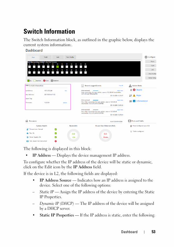
Switch InformationThe Switch Information block, as outlined in the graphic below, displays the current system information:.
The following is displayed in this block:
• IP Address — Displays the device management IP address.
To configure whether the IP address of the device will be static or dynamic, click on the Edit icon by the IP Address field.
If the device is in L2, the following fields are displayed:
• IP Address Source — Indicates how an IP address is assigned to the device. Select one of the following options:
– Static IP — Assign the IP address of the device by entering the Static IP Properties.
– Dynamic IP (DHCP) — The IP address of the device will be assigned by a DHCP server.
• Static IP Properties — If the IP address is static, enter the following:
Dashboard 53

FILE LOCATION: C:\Users\vijaya_devakumar_dev\Documents\PowerConnect\Astute\Docs for Web Posting\Astute_Admin_Guide_sources_MIF7\FM\Dell_Astute_Dashboard.fm
D E L L C O N F I D E N T I A L – P R E L I M I N A R Y 3 / 1 9 / 1 5 - F O R P R O O F O N LY
– IP Version — The type is always IPv4.
– IP Address — Enter the IP address of the device.
– Subnet Mask — Enter the subnet mask of the IP address of the device.
– Gateway — Enter the prefix of the gateway.
• MAC Address — Displays the device MAC address.
• Asset Tag — Asset tag for the device. This is the user-defined reference for the device.
If the device is in L2+mode, the Edit page of IPv4 Addressing page is displayed.
• Firmware — Version of the firmware currently installed on the device. Click Update to update the firmware. This takes you to Update Firmware / Configuration.
54 Dashboard

FILE LOCATION: C:\Users\vijaya_devakumar_dev\Documents\PowerConnect\Astute\Docs for Web Posting\Astute_Admin_Guide_sources_MIF7\FM\Dell_Astute_Dashboard.fm
D E L L C O N F I D E N T I A L – P R E L I M I N A RY 3 / 1 9 / 1 5 - F O R P R O O F O N LY
ResourcesThe Resources block, as outlined in the graphic below, displays device information regarding the physical status of the device:
This block displays the following fields:
• Temperature — Normal or X for temperature above thresholds
• Fan On— Green check is On; red X is Off
• Power Supply — On or off (on devices supporting PoE input)
• PoE Input — Connected/not connected (on devices supporting PoE input). If power supply is off and PoE Input is connected, the device is delivering power.
The Bandwidth block displays device information regarding the physical status of the device. It displays the following fields:
• Average Daily Traffic — Average amount of traffic for the current day.
• Bandwidth Cap — Maximum amount of bandwidth available on the device.
Dashboard 55

FILE LOCATION: C:\Users\vijaya_devakumar_dev\Documents\PowerConnect\Astute\Docs for Web Posting\Astute_Admin_Guide_sources_MIF7\FM\Dell_Astute_Dashboard.fm
D E L L C O N F I D E N T I A L – P R E L I M I N A R Y 3 / 1 9 / 1 5 - F O R P R O O F O N LY
The Power Over Ethernet (PoE) block displays device information regarding the power output of the device. It displays the following fields:
• Power Budget — Amount of power that device can generate, as follows:
• X1008P — 8 PoE ports, budget: 120W
• X1018P — 16 PoE ports, budget: 240W
• X1026P — 12 PoE+ ports (1-12) + 12 PoE ports (13-24), budget: 360W
• X1052P — 12 PoE+ ports (1-12) + 12 PoE ports (13-24), budget: 360W
• X4012 — Not supported.
• Connected Powered Devices — Number of powered devices.
56 Dashboard

FILE LOCATION: C:\Users\vijaya_devakumar_dev\Documents\PowerConnect\Astute\Docs for Web Posting\Astute_Admin_Guide_sources_MIF7\FM\Dell_Astute_Dashboard.fm
D E L L C O N F I D E N T I A L – P R E L I M I N A RY 3 / 1 9 / 1 5 - F O R P R O O F O N LY
Recent Logged EventsThe Recent Logged Events block, as outlined in the graphic below, displays the three most recent logged events:
Click View All to display a list of all active alerts, or click the Active Alert level to see all the events logged for the alert level. Click Learn More to view detailed information about the displayed recent logged event.
Dashboard 57

FILE LOCATION: C:\Users\vijaya_devakumar_dev\Documents\PowerConnect\Astute\Docs for Web Posting\Astute_Admin_Guide_sources_MIF7\FM\Dell_Astute_Dashboard.fm
D E L L C O N F I D E N T I A L – P R E L I M I N A R Y 3 / 1 9 / 1 5 - F O R P R O O F O N LY
Active AlertsThe Active Alerts block, as outlined in the graphic below, displays the number of the various types of alerts.
Click View All to see the list of all active alerts or click the Active Alert level to see all the events logged for the alert level.
58 Dashboard

FILE LOCATION: C:\Users\vijaya_devakumar_dev\Documents\PowerConnect\Astute\Docs for Web Posting\Astute_Admin_Guide_sources_MIF7\FM\Dell_Astute_Dashboard.fm
D E L L C O N F I D E N T I A L – P R E L I M I N A RY 3 / 1 9 / 1 5 - F O R P R O O F O N LY
Ports and VLANsThe Ports and VLANs block, as outlined in the graphic below, displays important information about how the ports and VLANs are configured:
The following fields are displayed:
• Ports Configured Out Of — Number of ports that have been configured out of total ports on the device.
• VLANs — Number of VLANs configured on the device.
Click View All to select a port or VLAN and view its configuration.
Dashboard 59

FILE LOCATION: C:\Users\vijaya_devakumar_dev\Documents\PowerConnect\Astute\Docs for Web Posting\Astute_Admin_Guide_sources_MIF7\FM\Dell_Astute_Dashboard.fm
D E L L C O N F I D E N T I A L – P R E L I M I N A R Y 3 / 1 9 / 1 5 - F O R P R O O F O N LY
Configuration WizardsThe Configure block, as outlined in the graphic below, contains buttons to open the various configuration wizards.
Ports
To configure one or more ports:
1 Click on the Ports button from the dashboard and select one or more ports to configure.
2 Click Next.
3 Enter a description of the port(s) in Port Description (optional).
4 Click Next and enter the following:
– Port Status — Enable/disable traffic forwarding through the port.
• Up — Traffic is enabled through the port.
• Down — Traffic is disabled through the port.
60 Dashboard
FILE LOCATION: C:\Users\vijaya_devakumar_dev\Documents\PowerConnect\Astute\Docs for Web Posting\Astute_Admin_Guide_sources_MIF7\FM\Dell_Astute_Dashboard.fm
D E L L C O N F I D E N T I A L – P R E L I M I N A RY 3 / 1 9 / 1 5 - F O R P R O O F O N LY
– Re-Activate Suspended Port(s)—Select Enabled to reactive a port if the port has been disabled through the locked port security option or Disabled to leave it down.
5 Click Next.
6 Depending on the type of port being configured, enter the following fields:
Copper 10/100/1000MBase-T Ports
– Ports — Port numbers.
– Port Type — Port type.
– Admin Speed — Select the configured rate for the port. The port type determines the available speed setting options. You can designate Administrative Speed only when port auto-negotiation is disabled.
– Admin Duplex Mode — Select the port duplex mode (this is only possible if Auto Negotiation is not enabled). The options are:
• Full — The interface supports transmission between the device and the client in both directions simultaneously.
• Half — The interface supports transmission between the device and the client in only one direction at a time.
– Auto Negotiation — Select to enable/disable auto-negotiation on the port. Auto-Negotiation enables a port to advertise its transmission rate, duplex mode, and Flow Control abilities to other devices.
– Admin Advertisement — Check the auto-negotiation setting the port advertises. The possible options are:
• Max Capability — The port advertises all the options that it can support.
• 10 Half — The port advertises for a 10 mbps speed port and half duplex mode setting.
• 10 Full — The port advertises for a 10 mbps speed port and full duplex mode setting.
• 100 Half — The port advertises for a 100 mbps speed port and half duplex mode setting.
• 100 Full — The port advertises for a 100 mbps speed port and full duplex mode setting.
Dashboard 61

FILE LOCATION: C:\Users\vijaya_devakumar_dev\Documents\PowerConnect\Astute\Docs for Web Posting\Astute_Admin_Guide_sources_MIF7\FM\Dell_Astute_Dashboard.fm
D E L L C O N F I D E N T I A L – P R E L I M I N A R Y 3 / 1 9 / 1 5 - F O R P R O O F O N LY
• 1000 Full — The port advertises for a 1000 mbps speed port and full duplex mode setting.
– Energy Efficient Ethernet — Globally enable/disable Energy Efficient Ethernet.
– Energy Efficient Ethernet LLDP — Globally enable/disable the EEE LLDP advertisement feature.
– Short Reach Energy Saving — Globally enable/disable Short Reach Energy Saving feature.
– Back Pressure — Enable/disable Back Pressure mode that is used with Half Duplex mode to disable ports from receiving messages.
– Flow Control — Set flow control on the port. The following options are available:
• Enable/Disable — Enable/disable flow control on the port (Enabled is the default).
• Auto Negotiation — Enables auto-negotiation of flow control on the port.
– MDI/MDIX — Select one of the options that enables the device to decipher between crossed and uncrossed cables. Hubs and switches are deliberately wired opposite to the way end stations are wired, so that when a hub or switch is connected to an end station, a straight through Ethernet cable can be used, and the pairs are match up properly. When two hubs or switches are connected to each other, or two end stations are connected to each other, a crossover cable is used ensure that the correct pairs are connected. The possible options are:
• Auto — Use to automatically detect the cable type.
• MDIX — Use for hubs and switches.
• MDI — Use for end stations.
1Gbe SFP & 10GbE SFP+ Ports
– Ports — Port numbers.
– Port Type — Port type.
– Admin Speed — Select the configured rate for the port. The port type determines the available speed setting options. You can designate Administrative Speed only when port auto-negotiation is disabled.
62 Dashboard

FILE LOCATION: C:\Users\vijaya_devakumar_dev\Documents\PowerConnect\Astute\Docs for Web Posting\Astute_Admin_Guide_sources_MIF7\FM\Dell_Astute_Dashboard.fm
D E L L C O N F I D E N T I A L – P R E L I M I N A RY 3 / 1 9 / 1 5 - F O R P R O O F O N LY
– Admin Duplex Mode — Select the port duplex mode (this is only possible if Auto Negotiation is not enabled). The options are:
• Full — The interface supports transmission between the device and the client in both directions simultaneously.
• Half — The interface supports transmission between the device and the client in only one direction at a time.
– Flow Control — Set flow control on the port. The following options are available:
• Enable/Disable — Enable/disable flow control on the port (Enabled is the default).
• Auto Negotiation — Enables auto-negotiation of flow control on the port.
7 Click Next to view a summary of the port configuration.
8 Click Apply to save the changes.
LAGThe following processes can be performed in this wizard.
Assign Ports to a LAG
To assign ports to a LAG:
1 Select Assign Ports to a LAG.
2 Click Next.
3 Select one or more ports to assign to a LAG.
4 Enter the following fields:
– Port Edit Mode — Select one of the following options:
• Edit LAG Port Assignment — Use to modify the ports in the LAG.
• Clear LAG Port Assignment — Use to remove ports from the LAG.
– LAG ID — Select a LAG ID.
– Port VLAN Mode — Select either Access, General or Trunk. See Port Modes.
5 In the Assign Select Ports to VLAN and Port Tag Membership section, select whether ports will be Tagged or Untagged in the VLAN. This is possible for individual VLANs or All Future VLANs.
Dashboard 63

FILE LOCATION: C:\Users\vijaya_devakumar_dev\Documents\PowerConnect\Astute\Docs for Web Posting\Astute_Admin_Guide_sources_MIF7\FM\Dell_Astute_Dashboard.fm
D E L L C O N F I D E N T I A L – P R E L I M I N A R Y 3 / 1 9 / 1 5 - F O R P R O O F O N LY
6 Enter the following fields:
– PVID — Enter the number of the VLAN ID contained in ports.
– Native VLAN ID — Displays the VLAN used for untagged traffic to trunk ports. Click None if there is no VLAN for untagged traffic.
– Frame Type — Select the packet type accepted by the LAG. The possible options are:
• Admit All — Tagged and untagged packets are both accepted by the LAG.
• Admit Tagged Only — Only tagged packets are accepted by the LAG.
• Admit Untagged Only — Only untagged packets are accepted on the LAG.
• Ingress Filtering — Select to Enable or Disable ingress filtering on the ports in the LAG.
7 After reviewing the summary, click Apply to save the LAG configuration. After apply is selected the wizard will bring up LAG Configuration option.
Configure LAG
To configure a LAG:
1 Click View Current LAG Configuration. This describes the current LAG configurations:
– LAG — Displays the number of the LAG
– LAG Mode— Displays one of the following modes:
• Static — User-defined LAG.
• LACP — LACP-defined LAG
– PVID — Displays the number of the VLAN ID contained in ports.
– Administrative VLAN— Displays status of LAG (Up or Down) as it was configured.
– Operational VLAN— Displays actual status of LAG (Up or Down).
– Frame Type — Displays the port types that comprise the LAG.
• Ingress Filtering — Displays whether there is ingress filtering on the ports in the LAG.
2 Select Configure LAG.
64 Dashboard

FILE LOCATION: C:\Users\vijaya_devakumar_dev\Documents\PowerConnect\Astute\Docs for Web Posting\Astute_Admin_Guide_sources_MIF7\FM\Dell_Astute_Dashboard.fm
D E L L C O N F I D E N T I A L – P R E L I M I N A RY 3 / 1 9 / 1 5 - F O R P R O O F O N LY
3 Click Next.
4 Click on the Edit icon of a LAG and enter the following fields:
– LAG — Displays the number of the LAG
– LAG Mode— Select one of the following modes:
• Static — User-defined LAG.
• LACP — LACP-defined LAG
– Description — Enter descriptive text.
– LAG Type — Displays the port types that comprise the LAG.
– Admin Status — Select status of LAG (Up or Down).
– Admin Speed — Select speed of LAG.
– Auto Negotiation— Enable/disable auto negotiation.
– Auto Negotiation— Enable/disable auto negotiation.
– Admin Advertisement — Check the auto-negotiation setting the port advertises. The possible options are:
• Max Capability — The port advertises all the options that it can support.
• 10 Half — The port advertises for a 10 mbps speed port and half duplex mode setting.
• 10 Full — The port advertises for a 10 mbps speed port and full duplex mode setting.
• 100 Half — The port advertises for a 100 mbps speed port and half duplex mode setting.
• 100 Full — The port advertises for a 100 mbps speed port and full duplex mode setting.
• 1000 Full — The port advertises for a 1000 mbps speed port and full duplex mode setting.
– Neighbor Advertisement — Displays the neighboring port’s advertisement settings. The field values are identical to the Admin Advertisement field values.
– Flow Control — Select to enable or disable flow control.
5 Click Next to view a summary of the port configuration.
Dashboard 65
FILE LOCATION: C:\Users\vijaya_devakumar_dev\Documents\PowerConnect\Astute\Docs for Web Posting\Astute_Admin_Guide_sources_MIF7\FM\Dell_Astute_Dashboard.fm
D E L L C O N F I D E N T I A L – P R E L I M I N A R Y 3 / 1 9 / 1 5 - F O R P R O O F O N LY
6 Click Apply to save the changes.
Configure VLANThe following processes can be performed in this wizard.
Configure VLAN
To add a VLAN:
1 Select Configure VLAN.
2 Click Next and Add.
3 Enter the following fields:
– VLAN ID — Enter the number of the VLAN.
– VLAN Name — Enter the name of the VLAN.
– Authentication Required — Enable/disable Dot1x authentication.
4 Click OK.
5 Click Next to view the VLAN.
6 Click Apply to save the changes.
Configure and Assign Ports to VLAN
To add ports to a VLAN:
1 Select Configure and Assign Ports to VLAN.
2 Click Next.
3 Click on ports to be included in VLAN.
4 Enter the following fields:
– Port Edit Mode — Select whether you are going to configure the port or clear all existing VLAN configurations from the selected ports.
– Port VLAN Mode — Select either Access, General or Trunk. See Port Modes.
– Assign Select Ports to VLAN and Port Tag Membership — Select either All Future VLANs (for trunk ports) or the specific VLANs to which the port will be assigned.
5 Click OK.
6 Click Next to view a summary of the port configuration.
7 Click Apply to save the changes.
66 Dashboard

FILE LOCATION: C:\Users\vijaya_devakumar_dev\Documents\PowerConnect\Astute\Docs for Web Posting\Astute_Admin_Guide_sources_MIF7\FM\Dell_Astute_Dashboard.fm
D E L L C O N F I D E N T I A L – P R E L I M I N A RY 3 / 1 9 / 1 5 - F O R P R O O F O N LY
Port ProfileTo assign a port to be connected to a desktop PC, phone, switch, router or wireless access point:
1 Click Port Profile.
2 Click Next.
3 Select one or more ports to assign to a port profile.
4 Select Assign Port to Profile in Port Edit Mode field.
5 Select one of the following profiles to assign to ports:
– Desktop Interface — Used for increased network security and reliability when connecting a desktop device, such as a PC, to a switch port.
– Phone Interface — Used when connecting a desktop device, such as a PC, to an IP phone to a switch port. The voice data is tagged.
– Switch Interface — Used when connecting an access switch and a distribution switch or between access switches.
– Router Interface — Used when connecting the switch and a WAN router.
– Wireless Interface — Used when connecting the switch to a wireless access point.
6 Each profile requires entering various elements of VLAN information. Enter the fields according to the profile:
– VLAN Port Mode — Displays the port mode applied to ports in the profile.
– VLAN ID - Untagged — Enter the VLAN for untagged traffic.
– VLAN ID - Tagged — Enter the VLAN for tagged traffic.
– Native VLAN ID — Select and enter the VLAN ID used for untagged traffic to trunk ports.
The remaining fields on this page are display-only, and describe the port configuration of the profile. The following fields are described:
Port Security fields:
– Mode — Learning mode. The possible options are:
Dashboard 67

FILE LOCATION: C:\Users\vijaya_devakumar_dev\Documents\PowerConnect\Astute\Docs for Web Posting\Astute_Admin_Guide_sources_MIF7\FM\Dell_Astute_Dashboard.fm
D E L L C O N F I D E N T I A L – P R E L I M I N A R Y 3 / 1 9 / 1 5 - F O R P R O O F O N LY
• Classic Lock — Locks the port using the classic lock mechanism. The port is immediately locked, regardless of the number of addresses that have already been learned.
• Limited Dynamic Lock — Locks the port by deleting the dynamic MAC addresses associated with the port. The port learns up to the maximum addresses allowed on the port. Both relearning and aging MAC addresses are enabled.
– Max Entries — Displays the maximum number of MAC addresses that can be learned on the port.
– Action on Violation — Action to be applied to packets arriving on a locked port. The possible options are:
• Discard — Discard the packets from any unlearned source.
• Forward — Forward the packets from an unknown source, without learning the MAC address.
• Shutdown — Discard the packet from any unlearned source, and shut down the port. Ports remain shutdown until they are reactivated, or the device is reset.
7 Click Next to view the configuration.
8 Click Apply to save the changes.
Initial Setup
NOTE: This feature removes any saved configurations.
To configure the device using this wizard:
1 Click Initial Setup.
2 Click Next.
3 Enter the IP Address Source. Select one of the following options:
– Static IP — IP address manually selected.
– Dynamic IP (DHCP) — IP address assigned by DHCP server.
4 If the IP Address Source is Static IP, enter the fields:
– IP Version — Displays IPv4.
– VLAN ID — Displays the ID of the default VLAN.
– IP Address — Enter the device IP address.
68 Dashboard

FILE LOCATION: C:\Users\vijaya_devakumar_dev\Documents\PowerConnect\Astute\Docs for Web Posting\Astute_Admin_Guide_sources_MIF7\FM\Dell_Astute_Dashboard.fm
D E L L C O N F I D E N T I A L – P R E L I M I N A RY 3 / 1 9 / 1 5 - F O R P R O O F O N LY
– Subnet Mask — Enter the device subnet mask.
– Gateway — Enter the device default gateway.
5 Click Next.
6 Enter the following fields:
– Username — Enter a username.
– Password — Enter a password.
– Re-enter Password — Confirm the password.
7 Click Next.
8 Enter the following fields:
– MAC Address— Displays the device MAC address.
– System Name — Enter a system name.
– System Contact — Enter a system contact.
– System Location — Enter the systems location.
9 Click Next.
10 Enter the following fields:
– SNMP Mode — Enable/disable SNMP on the device.
– SNMP Community String — Enter the SNMP community string.
– SNMP Management System IP — Enter the SNMP management system IP address.
11 Click Next to view a summary of the port configuration.
12 Click Apply to save the changes.
Dashboard 69

FILE LOCATION: C:\Users\vijaya_devakumar_dev\Documents\PowerConnect\Astute\Docs for Web Posting\Astute_Admin_Guide_sources_MIF7\FM\Dell_Astute_Dashboard.fm
D E L L C O N F I D E N T I A L – P R E L I M I N A R Y 3 / 1 9 / 1 5 - F O R P R O O F O N LY
70 Dashboard

D E L L C O N F I D E N T I A L – P R E L I M I N A RY 3 / 1 9 / 1 5 - F O R P R O O F O N LY
6Switch ManagementThis section describes how to set system parameters, such as security features, switch software, system time, logging parameters and more.
It contains the following topics:
• IP Addressing Overview
• Switch Information
• IPv4 Addressing
• IPv6 Addressing
• File Update and Backup
• Domain Name System (DNS)
• Time Synchronization
• Management Security
IP Addressing OverviewThe device functions as an IPv6-compliant host, as well as an IPv4-host (also known as dual stack). This enables device operation in a pure-IPv6 network, while ISATAP tunnel enables device operations in combined in a combined IPv4/IPv6 network.
Difference Between IPv4 and IPv6 AddressingThe primary difference between IPv4 to IPv6 is the length of network addresses. IPv6 addresses are 128 bits, whereas IPv4 addresses are 32 bits. Thus, IPv6 addresses enable the use of many more unique addresses.
The 128-bit IPv6 address format is divided into eight groups of four hexadecimal digits. Abbreviation of this format by replacing a group of zeros with double colons (::) is acceptable. IPv6 address representation can be further simplified by suppressing the leading zeros.
All IPv6 address formats are acceptable, yet for display purposes, the system displays the most abbreviated form, which replaces groups of zeros with double colons and removes the leading zeros.
Template Last Updated - 2010 Switch Management 71

FILE LOCATION: C:\Users\vijaya_devakumar_dev\Documents\PowerConnect\Astute\Docs for Web Posting\Astute_Admin_Guide_sources_MIF7\FM\Dell_Astute_SwitchManagement.fm
D E L L C O N F I D E N T I A L – P R E L I M I N A R Y 3 / 1 9 / 1 5 - F O R P R O O F O N LY
IPv6 PrefixesWhile Unicast IPv6 addresses written with their prefix lengths are permitted, in practice their prefix lengths are always 64 bits, and therefore are not required to be expressed. Any prefix that is less than 64 bits is a route or address range that summarizes a portion of the IPv6 address space.
For every assignment of an IP address to an interface, the system runs the Duplicate Address Detection (DAD) algorithm to ensure uniqueness.
An intermediary transition mechanism is required for IPv6-only nodes to communicate with IPv6 nodes over an IPv4 infrastructure. The tunneling mechanism implemented is the Intra-Site Automatic Tunnel Addressing Protocol (ISATAP). This protocol treats the IPv4 network as a virtual IPv6 local-link, with each IPv4 address mapped to a Link Local IPv6 address.
Switch InformationUse the Switch Information page to view and configure general device information, including the system name, location, contact, system MAC Address, System Object ID, date, time, and system up time.
To configure general device parameters:
1 Click Switch Management > Switch Information.
2 Click Edit and enter the fields:
– System Name (0-160 Characters) — Enter the user-defined device name.
– System Contact (0-160 Characters) — Enter the name of the contact person.
– System Location (0-160 Characters) — Enter the location where the system is currently running.
– MAC Address — Displays the device MAC address, which is hard coded on the switch and thus not editable.
– Sys Object ID — Displays the vendor's authoritative identification of the network management subsystem contained in the entity.
– Date — Enter the current date (mandatory). If SNTP has been defined, but the SNTP server is not available, the switch uses the date and time in this field and the Time field. Otherwise this information is taken from the SNTP server.
72 Switch Management

FILE LOCATION: C:\Users\vijaya_devakumar_dev\Documents\PowerConnect\Astute\Docs for Web Posting\Astute_Admin_Guide_sources_MIF7\FM\Dell_Astute_SwitchManagement.fm
D E L L C O N F I D E N T I A L – P R E L I M I N A RY 3 / 1 9 / 1 5 - F O R P R O O F O N LY
– Time — Enter the current time (mandatory). If SNTP has been defined, but the SNTP server is not available, the switch uses the date and time in this field and the Date field. Otherwise this information is taken from the SNTP server.
– System Up Time — Displays the amount of time since the last device reset.
– Service Tag — Displays the service reference number used when servicing the device.
– Asset Tag — Enter the Asset Tag (0-16 Characters) for the device. This is the user-defined reference for the device.
– Serial No. — Displays the device serial number.
IPv4 AddressingYou can assign IPv4 addresses to an interface in the following ways:
• Static Assignment
• DHCP Assignment - Default
When the interface is configured as a DHCP client (the default), it requests an IP address from the DHCP server. It then sends Address Resolution Protocol (ARP) packets to confirm the uniqueness of the IP address. If the ARP response shows that the IP address is in use, the switch sends a DHCPDECLINE message to the DHCP server, and sends another DHCPDISCOVER packet that restarts the process.
If the DHCP server is not accessible, the device uses the default IP address 192.168.2.1.
Use the IPv4 Addressing page to configure a static device IPv4 address.
When an IP address is assigned, it is checked for uniqueness in the following way:
• A gratuitous ARP request is sent three times every three seconds.
• If after (3+1)*3 = 12 seconds the switch has not received the ARP response, the IP address is considered to be unique.
• During the procedure the switch has to reply to gratuitous ARP and probe ARP requests with the validated IP address.
Switch Management 73

FILE LOCATION: C:\Users\vijaya_devakumar_dev\Documents\PowerConnect\Astute\Docs for Web Posting\Astute_Admin_Guide_sources_MIF7\FM\Dell_Astute_SwitchManagement.fm
D E L L C O N F I D E N T I A L – P R E L I M I N A R Y 3 / 1 9 / 1 5 - F O R P R O O F O N LY
The IP address is assigned even if the above validation procedure concludes that the IP address in question is not unique, but a SYSLOG message is generated.
In addition to the above validation procedure every time a switch receives an ARP request with a sender IP address that is equal to its IP address defined on the input interface it sends a SYSLOG message informing of IP duplication, containing the sender IP and MAC addresses, from the received ARP message.
NOTE: System Routing Mode: X1008/P, X1018/P, X1026/P devices are in Layer 2 mode by default. X1052/P, X4012 devices are in Layer 2+ mode by default.
The X1008/P, X1018/P and X1026/P devices can be configured in either in L2 or L2+ mode. For these devices:
• In Layer 2 mode, the following are supported: Dot1x (guest VLAN, Dynamic VLAN Assignment, and Multi Session. Only one IP address can be assigned on a VLAN.
• In Layer 2 + Routing mode, the following are supported: IPv4 Routing and IPv6 Routing. Dot1x (guest VLAN, Dynamic VLAN Assignment, and Multi Session) is not supported. Multiple static IP addresses can be assigned on one or more interfaces (ports, LAGs or VLANs).
The X1052(P) and 4012 (P) devices are always in L2+ mode.
IPv4 Default GatewayA default gateway can be assigned on any IPv4 interface in the system (port, LAG or VLAN).
The IPv4 default gateway can be assigned statically or received from a DHCP server according to the configuration in the IPv4 Addressing page. The default gateway is received along with the IP address from the DHCP server. DHCP assignment is the default.
IPv4 AddressingTo assign an IP address to an IPv4 interface, and to define subnets to which traffic can be routed:
1 Click Switch Management > IPv4 Addressing.
The previously-assigned IP addresses are displayed.
74 Switch Management

FILE LOCATION: C:\Users\vijaya_devakumar_dev\Documents\PowerConnect\Astute\Docs for Web Posting\Astute_Admin_Guide_sources_MIF7\FM\Dell_Astute_SwitchManagement.fm
D E L L C O N F I D E N T I A L – P R E L I M I N A RY 3 / 1 9 / 1 5 - F O R P R O O F O N LY
2 To assign the IP address of the interface, on which IPv4 routing is enabled, click Edit, Add and enter the fields:
– Interface Type — Select the type of interface to be configured.
– Interface — Select the interface to be configured.
– IP Address Source— Select DHCP to have address assigned dynamically or Static.
– IP Address — Enter the IP address assigned to the device manually (only if the DHCP option was not selected).
– Address Class— Select either Subnet Mask or Prefix Length.
– Subnet Mask — Select the subnetwork mask to which traffic can be routed.
– Prefix Length — Enter the number of bits that comprise the IP address prefix of the subnetwork.
– Default Gateway— Enter the IP address of the default gateway if you did not enable DHCP. If DHCP is enabled, the default gateway is received from the DHCP server.
IPv6 AddressingThis section describes the following sections:
• IPv6 Global Parameters
• IPv6 Interface
• IPv6 Address
• IPv6 Default Gateway
• IPv6 Neighbors
Switch Management 75

FILE LOCATION: C:\Users\vijaya_devakumar_dev\Documents\PowerConnect\Astute\Docs for Web Posting\Astute_Admin_Guide_sources_MIF7\FM\Dell_Astute_SwitchManagement.fm
D E L L C O N F I D E N T I A L – P R E L I M I N A R Y 3 / 1 9 / 1 5 - F O R P R O O F O N LY
IPv6 Global ParametersTo define IPv6 global parameters:
1 Click Switch Management > IPv6 Addressing > Global Parameters.
2 Click Edit and enter values for the following fields:
• IPv6 Routing —Select Enable/Disable to enable/disable IPv6 routing. If this is not enabled, the device acts as a host (not a router) and can receive management packets, but cannot forward packets. If routing is enabled, the device can forward the IPv6 packets.
• ICMPv6 Error Rate Limit Interval (0-2147483647) — Enter how often the ICMPv6 error messages are generated in milliseconds. The value of this parameter together with the Bucket Size parameter (below) determines how many ICMP error messages may be sent per time interval, for example, a rate-limit interval of 100 ms and a bucket size of 10 messages translates to 100 ICMP error messages per second.
• ICMPv6 Error Rate Limit Bucket Size (1-200) — Enter the maximum number of ICMP error messages that can be sent by the device per interval. The value of this parameter together with the ICMP Error Rate Limit Interval parameter determines how many ICMP error messages may be sent per time interval, for example, a rate-limit interval of 100 ms and a bucket size of 10 messages translates to 100 ICMP error messages per second.
• IPv6 Hop Limit (1-255) —Enter the maximum number of intermediate routers on its way to the final destination to which a packet can pass. Each time a packet is forwarded to another router, the hop limit is reduced. When the hop limit becomes zero, the packet is discarded. This prevents packets from being transferred endlessly.
• IPv6 Link Local Default Zone Interface — Select an interface to egress a link local packet without a specified interface or with the default zone 0.
IPv6 Interface To add a new IPv6 interface:
1 Click Switch Management > IPv6 Addressing > IPv6 Interface.
The currently-defined IPv6 addresses on the selected interface are displayed.
76 Switch Management

FILE LOCATION: C:\Users\vijaya_devakumar_dev\Documents\PowerConnect\Astute\Docs for Web Posting\Astute_Admin_Guide_sources_MIF7\FM\Dell_Astute_SwitchManagement.fm
D E L L C O N F I D E N T I A L – P R E L I M I N A RY 3 / 1 9 / 1 5 - F O R P R O O F O N LY
2 Click Edit, Add and enter the fields:
– Interface Type — Select the type of interface to be configured.
– Interface — Select the interface to be configured.
– Duplicate Address Attempts — Number of consecutive neighbor solicitation messages that are sent on an interface while Duplicate Address Detection (DAD) is performed on Unicast IPv6 addresses on this interface. New addresses remain in a tentative state while duplicate address detection is performed. A field value of 0, disables duplicate address detection processing on the specified interface. A field value of 1, indicates a single transmission without follow up transmissions.
NOTE: A field value of 0, disables duplicate address detection processing on the specified interface. A field value of 1, indicates a single transmission without follow up transmissions.
– Autoconfiguration — Enable/disable stateless auto configuration of IPv6 address assignment. When enabled, the router solicitation ND procedure is initiated. This discovers a router in order to assign an IP address to the interface, based on prefixes received with RA messages. When auto configuration is disabled, no automatic assignment of IPv6 global Unicast addresses is performed, and existing, automatically-assigned IPv6 global Unicast addresses are removed from the interface.
– Send ICMP Unreachable — Enable/disable transmission of ICMPv6 address Unreachable messages. When enabled, unreachable messages are generated for any packet arriving on the interface with unassigned TCP/UDP port.
– IPv6 Redirects — Enable the sending of ICMP IPv6 redirect messages to re-send a packet through the same interface on which the packet was received.
– DHCPv6 Client Stateless—Select to enable the interface to receive configuration information from a DHCP server.
– Minimum Information Refresh Time (600-4294967294) —This value is used to put a floor on the refresh time value. If the server sends a refresh time option that is less than this value, this value is used instead. Select either Infinite (no refresh unless the server sends this option) or User Defined to set a value.
Switch Management 77

FILE LOCATION: C:\Users\vijaya_devakumar_dev\Documents\PowerConnect\Astute\Docs for Web Posting\Astute_Admin_Guide_sources_MIF7\FM\Dell_Astute_SwitchManagement.fm
D E L L C O N F I D E N T I A L – P R E L I M I N A R Y 3 / 1 9 / 1 5 - F O R P R O O F O N LY
– Information Refresh Time (86400-4294967294)—This value indicates how often the device will refresh information received from the DHCPv6 server. If this option is not received from the server, the value entered here is used. Select either Infinite (no refresh unless the server sends this option) or User Defined to set a value
IPv6 Address To define the IPv6 address on an IPv6 interface:
1 Click Switch Management > IPv6 Addressing > IPv6 Address.
2 Click Edit.
3 To enable IPv6 support on this interface, click Edit, Add and enter the following fields:
– Interface — Select the interface for the address to be defined on.
– IPv6 Address Type — Select the type of IP address added to the interface. The possible options are:
• Link Local — The IP address is link local; non-routable and can be used for communication on the same network only. A Link Local address has a prefix of 'FE80'.
• Global — The IP address is a globally unique IPv6 address; visible and reachable from other subnets.
– IP Address — Enter the IPv6 address assigned to the interface. The address must be a valid IPv6 address, specified in hexadecimal using 16-bit values between colons. An example of an IPv6 address is 2031:0:130F:0:0:9C0:876A:130D and the compressed version is represented as 2031:0:130F::9C0:876A:130D. Up to five IPv6 addresses (not including Link Local addresses) can be set per interface, with the limitation of up to128 addresses per system.
– Prefix Length — For global Unicast or Anycast, enter the length of the IPv6 prefix. The length is a decimal value that indicates how many of the high-order contiguous bits of the address comprise the prefix (the network portion of the address). The Prefix field is applicable only on a static IPv6 address defined as a Global IPv6 address.
– EUI-64 — For global Unicast or Anycast, select to enable the EUI-64 option, which disables the Prefix Length text box.
78 Switch Management

FILE LOCATION: C:\Users\vijaya_devakumar_dev\Documents\PowerConnect\Astute\Docs for Web Posting\Astute_Admin_Guide_sources_MIF7\FM\Dell_Astute_SwitchManagement.fm
D E L L C O N F I D E N T I A L – P R E L I M I N A RY 3 / 1 9 / 1 5 - F O R P R O O F O N LY
IPv6 Default Gateway Use the IPv6 Default Gateway page to configure and view the default IPv6 router addresses. This list contains routers that are candidates to become the switch default router for non-local traffic. The switch randomly selects a router from the list. The switch supports one static IPv6 default router. Dynamic default routers are routers that have sent router advertisements to the switch IPv6 interface.
When adding or deleting IP addresses, the following events occur:
• When removing an IP interface, all of its default gateway IP addresses are removed.
• Dynamic IP addresses cannot be removed.
• An alert message is displayed after a user attempts to insert more than one IP address.
• An alert message is displayed when attempting to insert a non-Link Local type address.
To configure a router:
1 Click Switch Management > IPv6 Addressing > IPv6 Default Gateway.
The previously-defined routers are displayed with the following fields:
– Default Gateway IPv6 Address — The router’s address.
– Interface — The interface on which the router is accessed.
– Type — The means by which the default gateway was configured. The possible options are:
• Static — The default gateway is user-defined.
• Dynamic — The default gateway is dynamically configured through router advertisement.
– State — The router’s status when device is in Layer 2 mode. The possible options are:
• Incomplete — Address resolution is in progress and the link-layer address of the default gateway has not yet been determined.
• Reachable — The default gateway is known to have been reachable recently (within tens of seconds ago).
Switch Management 79
FILE LOCATION: C:\Users\vijaya_devakumar_dev\Documents\PowerConnect\Astute\Docs for Web Posting\Astute_Admin_Guide_sources_MIF7\FM\Dell_Astute_SwitchManagement.fm
D E L L C O N F I D E N T I A L – P R E L I M I N A R Y 3 / 1 9 / 1 5 - F O R P R O O F O N LY
• Stale — The default gateway is no longer known to be reachable but until traffic is sent to the default gateway, no attempt is made to verify its reachability.
• Delay— The default gateway is no longer known to be reachable, and traffic has recently been sent to the default gateway. Rather than probe the default gateway immediately, however, there is a delay sending probes for a short while in order to give upper-layer protocols a chance to provide reachability confirmation.
• Probe — The default gateway is no longer known to be reachable, and Unicast Neighbor Solicitation probes are being sent to verify reachability.
• Unreachable — No reachability confirmation was received.
– Metric — (In Layer 2+) Cost of this hop.
2 To add an IPv6 default gateway, click Edit, Add, and enter the fields:
– IPv6 Address Type — Displays that the IP address was added to the interface through a link local address.
– Link Local Interface — Displays the outgoing interface through which the default gateway can be reached.
– Default Gateway IPv6 Address — Enter the Link Local IPv6 address of the default gateway.
– Metric — Enter the cost of this hop.
NOTE: When defining a default gateway interface, ensure that the interface is in Layer 2+ mode (on devices supporting a separate Layer 2 mode). This can be done via the Voice VLAN page.
IPv6 Neighbors The IPv6 Neighbors feature is similar in functionality to the IPv4 Address Resolution Protocol (ARP) feature. It enables detecting Link Local addresses within the same subnet, and includes a database for maintaining reachability information about active neighbors.
The device supports a total of up to 64 neighbors, obtained statically or dynamically.
When removing an IPv6 interface, all neighbors entered statically or learned dynamically, are removed.
80 Switch Management

FILE LOCATION: C:\Users\vijaya_devakumar_dev\Documents\PowerConnect\Astute\Docs for Web Posting\Astute_Admin_Guide_sources_MIF7\FM\Dell_Astute_SwitchManagement.fm
D E L L C O N F I D E N T I A L – P R E L I M I N A RY 3 / 1 9 / 1 5 - F O R P R O O F O N LY
To add an IPv6 neighbor:
1 Click Switch Management > IPv6 Addressing > IPv6 Neighbors.
The following fields are displayed for previously-defined neighbors:
– Interface—Interface connected to the neighbor.
– IPv6 Address—IPv6 address of the neighbor.
– MAC Address—MAC address of the neighbor.
– Type—Neighbor discovery cache information entry type (Static or Dynamic).
– State — The possible states are:
• Incomplete — An address resolution is in progress, and the link-layer address of the neighbor has not yet been determined.
• Reachable — The neighbor is known to have been reachable recently (within tens of seconds).
• Stale — The neighbor is no longer known to be reachable, but until traffic is sent to the neighbor, no attempt is made to verify its reachability.
• Delay — The neighbor is no longer known to be reachable, and traffic has recently been sent to the neighbor. Rather than probe the neighbor immediately, however, there is a delay sending probes for a short while, in order to give upper-layer protocols a chance to provide reachability confirmation.
• Probe — The neighbor is no longer known to be reachable, and Unicast Neighbor Solicitation probes are being sent to verify reachability.
– Router—Whether the neighbor is a router (Yes or NA).
2 To add a new IPv6 neighbor, click Edit, Add, and enter the fields:
– IPv6 Interface — Displays the interface on which the IPv6 address is defined.
– IPv6 Address — Enter the neighbor IPv6 address.
– MAC Address — Enter the MAC address assigned to the interface.
3 To modify or remove an IPv6 neighbor, click Edit, and enter the fields described above page.
Switch Management 81

FILE LOCATION: C:\Users\vijaya_devakumar_dev\Documents\PowerConnect\Astute\Docs for Web Posting\Astute_Admin_Guide_sources_MIF7\FM\Dell_Astute_SwitchManagement.fm
D E L L C O N F I D E N T I A L – P R E L I M I N A R Y 3 / 1 9 / 1 5 - F O R P R O O F O N LY
If an entry for the specified IPv6 address already exists in the neighbor discovery cache, as learned through the IPv6 neighbor discovery process, you can convert the entry to a static entry. To do this, select Static in the Type field.
82 Switch Management

FILE LOCATION: C:\Users\vijaya_devakumar_dev\Documents\PowerConnect\Astute\Docs for Web Posting\Astute_Admin_Guide_sources_MIF7\FM\Dell_Astute_SwitchManagement.fm
D E L L C O N F I D E N T I A L – P R E L I M I N A RY 3 / 1 9 / 1 5 - F O R P R O O F O N LY
File Update and BackupThis section describes how to manage device firmware (image files) and configuration files. It contains the following topics:
• Overview
• Update Firmware / Configuration
• Backup Files
• Active Firmware Image
• Auto-Update
• Restore Factory Defaults
OverviewThis section describes the system files found in the system and how they can be updated (downloaded) and backed up (uploaded).
NOTE: Update Firmware / configuration downloads to the switch. Backup Files downloads from the switch.
System Files
The following system files are maintained on the system:
• Startup Configuration File — This file contains the commands used to configure the device at startup or after reboot. The Startup Configuration file can be created from the Running Configuration file or by downloading a file to the Startup Configuration file (in File Update and Backup).
• Running Configuration File — This file contains all Startup Configuration file commands, as well as all commands entered during the current session. After the device is powered down or rebooted, all commands stored in the Running Configuration file are lost.
During the startup process, all commands in the Startup Configuration file are copied to the Running Configuration file, and applied to the device.
During the session, new configuration commands are added to the Running Configuration file. To update the Startup Configuration file with these configuration commands, the Running Configuration file must first be copied to the Startup Configuration file before powering down the
Switch Management 83

FILE LOCATION: C:\Users\vijaya_devakumar_dev\Documents\PowerConnect\Astute\Docs for Web Posting\Astute_Admin_Guide_sources_MIF7\FM\Dell_Astute_SwitchManagement.fm
D E L L C O N F I D E N T I A L – P R E L I M I N A R Y 3 / 1 9 / 1 5 - F O R P R O O F O N LY
device. This can be done manually by clicking the Tools icon or by selecting save to Startup-config file within the page.
• Image Files — Files with extension .ros. Software images are saved in two flash files called Image 1 and Image 2. The active image contains the active copy, while the other image contains a backup copy. The device boots and runs from the active image. If the active image is corrupted, the system automatically boots from the non-active image. This is a safety feature for faults occurring during the software upgrade process.
• Boot Code — Files with extension .rfb are boot code, which is used to update the Boot Code Version.
Updating System Files
System files can be updated or initially loaded in one of the following ways:
• Manually—System files can be updated manually using the "Update Firmware / Configuration" on page 84 page.
• Automatically (Auto Update/Configuration)—System files can be updated automatically, as follows:
– Auto-Configuration—If the Auto-Configure feature is enabled (in the "Auto-Update" on page 88 page), the Startup Configuration file is automatically updated after reboot via an inserted USB key or from the DHCP server.
– Auto-Update—If the Firmware Auto-Update feature is enabled in the "Auto-Update" on page 88 page, the image file is automatically updated via an inserted USB key or from the DHCP server after reboot.
Update Firmware / Configuration
Software and configuration files can be downloaded from an external device using HTTP or TFTP (TFTP to switch).
To download a configuration or image file:
1 Click Switch Management > File Update and Backup > Update Firmware / Configuration.
The current firmware version is displayed.
2 Click Edit.
84 Switch Management

FILE LOCATION: C:\Users\vijaya_devakumar_dev\Documents\PowerConnect\Astute\Docs for Web Posting\Astute_Admin_Guide_sources_MIF7\FM\Dell_Astute_SwitchManagement.fm
D E L L C O N F I D E N T I A L – P R E L I M I N A RY 3 / 1 9 / 1 5 - F O R P R O O F O N LY
3 Enter the following IP Format fields:
– Supported IP Format — Select whether IPv4 or IPv6 format is supported.
– IPv6 Address Type — When the server supports IPv6, this specifies the type of static address supported. The possible options are:
• Link Local — A Link Local address that is non-routable and used for communication on the same network only.
• Global — A globally unique IPv6 address; visible and reachable from different subnets.
4 Enter the following File Type and Protocol fields:
– File Type— Select the type of files to be downloaded to the device. The possible options are:
• Firmware Download — A firmware file is downloaded.
• Configuration Download — A configuration file is downloaded.
– Update Method — Select the download method to be used. The possible options are:
• HTTP — Download file using HTTP
• TFTP — Download file using TFTP
• USB — Download from a USB drive
• Flash — Download from Flash memory
– Server IP Address — Enter server address where the file to be downloaded is stored.
– Source File Name — Enter the name of the file to be downloaded.
– Destination File Type — Name of type of file to be downloaded. The possible options are:
• Software Image — Downloads the image file. The image file overwrites the non-active image. It is recommended to designate that the non-active image becomes the active image after reset, and then to reset the device following the download. During the Image file download a dialog box opens that displays the download progress, and browsing is disabled.
• Boot Code — Downloads the boot file.
Switch Management 85
FILE LOCATION: C:\Users\vijaya_devakumar_dev\Documents\PowerConnect\Astute\Docs for Web Posting\Astute_Admin_Guide_sources_MIF7\FM\Dell_Astute_SwitchManagement.fm
D E L L C O N F I D E N T I A L – P R E L I M I N A R Y 3 / 1 9 / 1 5 - F O R P R O O F O N LY
– Destination File Name — Name of downloaded file on the device. The possible options are:
• Running Configuration — Check to download commands into the Running Configuration file. The current file is overwritten.
• Startup Configuration — Check to download commands into the Startup Configuration file. The current file is overwritten.
• New File Name — Check to copy commands into a file in flash memory. Enter the filename.
5 Click OK to start the upload process.
Backup FilesTo back up the Running Configuration, Startup Configuration or software image file from the switch:
1 Click Switch Management > File Update and Backup > Backup Files.
The current firmware version is displayed.
2 Click Edit.
3 Enter the following IP Format fields:
– Supported IP Format — Select whether IPv4 or IPv6 format is supported.
– IPv6 Address Type — When the server supports IPv6, this specifies the type of static address supported. The possible options are:
• Link Local — A Link Local address that is non-routable and used for communication on the same network only.
• Global — A globally unique IPv6 address; visible and reachable from different subnets.
4 Enter the following File Type and Protocol fields:
– Transfer File Name — Select the file type to be backed up. The possible options are:
• Running Configuration — Check to download commands into the Running Configuration file. The current file is overwritten.
• Startup Configuration — Check to download commands into the Startup Configuration file. The current file is overwritten.
86 Switch Management

FILE LOCATION: C:\Users\vijaya_devakumar_dev\Documents\PowerConnect\Astute\Docs for Web Posting\Astute_Admin_Guide_sources_MIF7\FM\Dell_Astute_SwitchManagement.fm
D E L L C O N F I D E N T I A L – P R E L I M I N A RY 3 / 1 9 / 1 5 - F O R P R O O F O N LY
• Software Image —Name of software image file.
– Backup Method — Select the backup method to be used. The possible options are:
• HTTP — Backup file using HTTP
• TFTP — Backup file using TFTP
• USB — Backup to USB drive
• Flash — Backup to Flash memory. It is suggested to use the same name for each configuration backup to the Flash, since the storage space on the Flash is limited. If you have CLI access to the device, you can use the dir command to view the contents of the Flash file system.
– Server IP Address — Enter server address where backup file is to be stored.
– Destination File Name — Name of backup file.
5 Click Apply to start the backup process.
NOTE: Each exclamation mark (!) that is displayed on the screen after you click Apply indicates that ten packets were successfully transferred.
Active Firmware Image
There are two firmware images, Image1 and Image2, stored on the switch. One of these images is identified as the active image, and the other is identified as the not active image. The switch boots from the active image.
You can switch the inactive image to the active image, and then reboot the switch.
To select the image file to be used after reset:
1 Click Switch Management > File Update and Backup > Active Firmware Image.
2 Click Edit.
The following fields are displayed:
– Current Firmware Version — The version of the image file that is currently active on the device.
Switch Management 87

FILE LOCATION: C:\Users\vijaya_devakumar_dev\Documents\PowerConnect\Astute\Docs for Web Posting\Astute_Admin_Guide_sources_MIF7\FM\Dell_Astute_SwitchManagement.fm
D E L L C O N F I D E N T I A L – P R E L I M I N A R Y 3 / 1 9 / 1 5 - F O R P R O O F O N LY
– Apply Version After Reboot — Select one of the possible versions of the image to be active after reset.
3 Click OK to select the image file to be used.
Auto-UpdateThe Auto-Update feature enables initial configuration of the device and upgrading of the firmware through an automatic process, which enables the administrator to ensure that the configuration and firmware of all the devices in the network is up-to-date.
The required configuration files or images are stored on a TFTP server or USB storage, and these are downloaded to all the devices in the network when the device boots up instead of booting from a local startup configuration file.
Auto-Update also enables quick installation of new devices on the network, since an out-of-box device can be configured to retrieve its configuration file from the network, allowing instant access to it from the administrator's management station and up-to-date configuration on the device.
Triggering the Auto Update of Configuration/Image File Process
When the Auto-Update feature is enabled (in the Auto Update of Configuration/Image File page), the device automatically attempts to download a new image or configuration file (under certain circumstances) using one of the following processes:
• The Auto-Update from a TFTP server is triggered if the following conditions are fulfilled:
– An IP address of a TFTP server is received from a DHCP server.
– A file name is received from DHCP server.
• The Auto-Configuration from a TFTP server is triggered if the following conditions are fulfilled:
– The switch as DHCP client received a configuration file name or a TFTP URL.
– Force Configuration Download at Next Startup is enabled in the Auto-Update page.
– The Startup Configuration file is empty.
See Preparations for Using Auto Configuration from a TFTP Server.
88 Switch Management
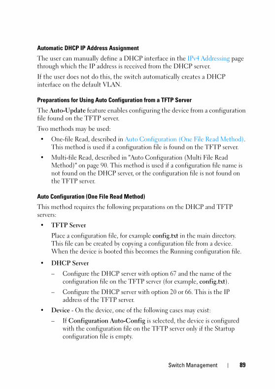
FILE LOCATION: C:\Users\vijaya_devakumar_dev\Documents\PowerConnect\Astute\Docs for Web Posting\Astute_Admin_Guide_sources_MIF7\FM\Dell_Astute_SwitchManagement.fm
D E L L C O N F I D E N T I A L – P R E L I M I N A RY 3 / 1 9 / 1 5 - F O R P R O O F O N LY
Automatic DHCP IP Address Assignment
The user can manually define a DHCP interface in the IPv4 Addressing page through which the IP address is received from the DHCP server.
If the user does not do this, the switch automatically creates a DHCP interface on the default VLAN.
Preparations for Using Auto Configuration from a TFTP Server
The Auto-Update feature enables configuring the device from a configuration file found on the TFTP server.
Two methods may be used:
• One-file Read, described in Auto Configuration (One File Read Method). This method is used if a configuration file is found on the TFTP server.
• Multi-file Read, described in "Auto Configuration (Multi File Read Method)" on page 90. This method is used if a configuration file name is not found on the DHCP server, or the configuration file is not found on the TFTP server.
Auto Configuration (One File Read Method)
This method requires the following preparations on the DHCP and TFTP servers:
• TFTP Server
Place a configuration file, for example config.txt in the main directory. This file can be created by copying a configuration file from a device. When the device is booted this becomes the Running configuration file.
• DHCP Server
– Configure the DHCP server with option 67 and the name of the configuration file on the TFTP server (for example, config.txt).
– Configure the DHCP server with option 20 or 66. This is the IP address of the TFTP server.
• Device - On the device, one of the following cases may exist:
– If Configuration Auto-Config is selected, the device is configured with the configuration file on the TFTP server only if the Startup configuration file is empty.
Switch Management 89

FILE LOCATION: C:\Users\vijaya_devakumar_dev\Documents\PowerConnect\Astute\Docs for Web Posting\Astute_Admin_Guide_sources_MIF7\FM\Dell_Astute_SwitchManagement.fm
D E L L C O N F I D E N T I A L – P R E L I M I N A R Y 3 / 1 9 / 1 5 - F O R P R O O F O N LY
– If Force Configuration Download at Next Startup is selected, the device is configured with the configuration file on the TFTP server whether the Startup configuration file is not empty or not.
Auto Configuration (Multi File Read Method)
If the one-file method has failed and the TFTP Server IP address has been provided by the DHCP Server, the switch applies the multi-file method to download the configuration file. The following steps are performed by the switch:
• The switch gets the hostname, as described below.
– If the hostname was provided by the DHCP server, this hostname is used.
– If the hostname has not been provided by a DHCP server, and if the user has configured the sysName variable, its value is used as a hostname.
– If neither of the above occurred, the switch uses the fp-net.cfg Filename List on the TFTP server. Each file in this list is a text file containing commands, each of which:
• Occupies one line.
• Has the following format: ip host hostname ip-addr. Each line maps an IP address to a hostname. When the switch identifies its own IP address in this list, the hostname associated with it is used.
• The switch tries to download a configuration file with the following names:
– hostname-config
– hostname.cfg if the previous file does not exist
– host.cfg if the previous files do not exist
Preparations for Firmware Image Download from TFTP
When an image file is downloaded from TFTP, the following steps are performed:
• The switch downloads the Indirect Image File and extracts from it the name of the image file.
NOTE: If the size of the image name bigger than 160 octets only the first 160 octets will be used.
90 Switch Management

FILE LOCATION: C:\Users\vijaya_devakumar_dev\Documents\PowerConnect\Astute\Docs for Web Posting\Astute_Admin_Guide_sources_MIF7\FM\Dell_Astute_SwitchManagement.fm
D E L L C O N F I D E N T I A L – P R E L I M I N A RY 3 / 1 9 / 1 5 - F O R P R O O F O N LY
• If the image file version differs from the current image file version, then the image file is loaded and the switch is rebooted.
Using DHCP and TFTP servers require the following preparations:
• TFTP Server
– Create a sub directory in the main directory. Place a software image file in it.
– Create an indirect file that contains a path and the name of the software version (for example indirect-Astute.txt that contains VRTX\VRTX-version.ros).
– Copy this file to the TFTP server’s main directory
• DHCP Server
– Configure the DHCP server with option 20 or 66. This is the IP address of the TFTP server.
– Configure the DHCP server with option 125. Enter the following information:
• A2-02-00-00 — Enterprise Number 674. It should be written from right to left. 674=02 a2
• 15 — Data Length
• 01 — Sub option code 1
• 13 — Sub option length
• Conversion of the file name (in the above example: conversion of indirect-Astute.txt from ASCII to HEX - 69-6E-64-69-72-65-63-74-2D-63-6F-6E-74-61-78-2E-74-78-74
Auto Update of Configuration/Image File
To set the auto update and configuration parameters:
NOTE: For the automatic options in this page to work the following must be implemented:
• Since Auto-Config depends on retrieving information from a DHCP server, the startup configuration needs to include a DHCP IP interface. The device is defined as a DHCP client, as described in IPv6 Interface or IPv4 Addressing. After reboot, this command is not saved in the Startup configuration.
• Preparations described above must be completed on the DHCP server and TFTP servers.
Switch Management 91

FILE LOCATION: C:\Users\vijaya_devakumar_dev\Documents\PowerConnect\Astute\Docs for Web Posting\Astute_Admin_Guide_sources_MIF7\FM\Dell_Astute_SwitchManagement.fm
D E L L C O N F I D E N T I A L – P R E L I M I N A R Y 3 / 1 9 / 1 5 - F O R P R O O F O N LY
1 Click Switch Management > File Update and Backup > Auto Update of Configuration/Image File.
The auto-update-configuration options are displayed.
2 Modify the auto-update configuration parameters as required:
– Configuration Auto-Configure — Enable/disable automatic download of the configuration parameters to the Running Configuration file. By default, this occurs only if the Startup Configuration file is empty.
– Firmware Auto-Update — Enable/disable automatic download of the image file.
– Force Configuration Download at Next Startup — Enable/disable the Configuration Auto Update option to work even if the Startup Configuration file is not empty.
– Auto Copy Running Configuration to Startup Configuration After Download — Enable/disable the Running Configuration file to be automatically copied to the Startup Configuration file after downloading the Running Configuration file.
Restore Factory DefaultsTo restore factory defaults:
1 Click Switch Management > File Update and Backup > Restore Factory Defaults.
2 Click Edit.
3 Select Restore Switch Configuration to replace the current configuration settings by the factory configuration default settings.
Domain Name System (DNS)The Domain Name feature enables configuring the usage of site names in place of IP addresses. It contains the following topics:
• DNS Settings
• Host Name Mapping
92 Switch Management

FILE LOCATION: C:\Users\vijaya_devakumar_dev\Documents\PowerConnect\Astute\Docs for Web Posting\Astute_Admin_Guide_sources_MIF7\FM\Dell_Astute_SwitchManagement.fm
D E L L C O N F I D E N T I A L – P R E L I M I N A RY 3 / 1 9 / 1 5 - F O R P R O O F O N LY
DNS SettingsThe Domain Name System (DNS) converts user-defined domain names into IP addresses. Each time a domain name is assigned, the DNS service translates the name into a numeric IP address, for example, www.ipexample.com is translated into 192.87.56.2. DNS servers maintain domain name databases and their corresponding IP addresses.
To add a DNS server and specify the active DNS server:
1 Click Switch Management > DNS Settings (DNS) > DNS Settings.
The list of previously-defined DNS servers is displayed.
2 Enter the following fields:
– DNS Status—Select Enable to enable mapping of host names into IP addresses through a DNS server.
– Domain Name Query Interval(20-3600)— Enter how often DNS queries will be sent.
3 To activate one of the currently-defined DNS servers, enable Active Server.
4 To add a DNS server, click Add, and enter the fields:
– Supported IP Format — Select whether the IPv4 or IPv6 format is supported.
– IPv6 Address Type — When the server supports IPv6, this specifies the type of static address supported. The possible options are:
• Link Local — A Link Local address that is non-routable and used for communication on the same network only.
• Global — A globally unique IPv6 address; visible and reachable from different subnets.
– Link Local Interface — When the server supports an IPv6 Link Local address, this specifies the Link Local interface. The possible options are:
• VLAN 1 — The VLAN on which the IPv6 interface is configured.
• ISATAP — The IPv6 interface is configured on an ISATAP tunnel.
– DNS Server — Enter the IP address of the DNS server being added.
Switch Management 93

FILE LOCATION: C:\Users\vijaya_devakumar_dev\Documents\PowerConnect\Astute\Docs for Web Posting\Astute_Admin_Guide_sources_MIF7\FM\Dell_Astute_SwitchManagement.fm
D E L L C O N F I D E N T I A L – P R E L I M I N A R Y 3 / 1 9 / 1 5 - F O R P R O O F O N LY
– DNS Server Currently Active — Displays the DNS server that is currently active.
– Set DNS Server Active — Check to activate the selected DNS server.
Host Name Mapping Host names can be dynamically mapped to IP addresses from the DNS servers specified in the DNS Settings page, or statically through the Host Name Mapping page.
To assign IP addresses to static host names.
1 Click Switch Management > Domain Name (DNS) > Host Name Mapping.
The currently-defined host names are displayed.
2 Click Add to add a new host name. Up to four IP addresses can be added.
3 For each IP address, enter the fields:
– Supported IP Format — Select whether the IPv4 or IPv6 format is supported.
– IPv6 Address Type — When the server supports IPv6, this specifies the type of static address supported. The possible options are:
• Link Local — A Link Local address that is non-routable and used for communication on the same network only.
• Global — A globally unique IPv6 address; visible and reachable from different subnets.
– Link Local Interface — When the server supports an IPv6 Link Local address, this specifies the Link Local interface. The possible options are:
• VLAN — The VLAN on which the IPv6 interface is configured.
• ISATAP — The IPv6 interface is configured on an ISATAP tunnel.
• Host Name (1-158 Characters) — Enter the host name to be associated with the IP address entered below.
• IP Address — Enter the IP address of the domain. Four addresses can be entered.
94 Switch Management

FILE LOCATION: C:\Users\vijaya_devakumar_dev\Documents\PowerConnect\Astute\Docs for Web Posting\Astute_Admin_Guide_sources_MIF7\FM\Dell_Astute_SwitchManagement.fm
D E L L C O N F I D E N T I A L – P R E L I M I N A RY 3 / 1 9 / 1 5 - F O R P R O O F O N LY
Time Synchronization The system clock runs from the moment the system starts up and keeps track of the date and time.
The date and time may be either set manually, or it may be received from an SNTP server.
This section describes how to set system time, and contains the following topics:
• Clock Source
• Local Time Settings
• System Time from an SNTP Server
– SNTP Global Settings
– SNTP Authentication
– SNTP Servers
– SNTP Interface Settings
Clock SourceSystem time can be set manually, or it may be received from an external SNTP server. To set the system time manually, there is no need to use the Clock Source page, because the default is manual (local) system time.
To set the clock source to SNTP:
1 Click Switch Management > Time Synchronization > Clock Source.
2 Select the Clock Source. The possible options are:
– Local —System time is taken from the device’s internal clock. Set this as defined in Local Time Settings.
– SNTP — System time is set via an SNTP server. Set SNTP parameters as defined in System Time from an SNTP Server.
Local Time SettingsUse the Local Time Settings page to set system date/time manually (as opposed to receiving them from an external SNTP server).
If system time is acquired from an external SNTP clock and the external SNTP clock is not received for some reason, the manual system time is used.
Switch Management 95
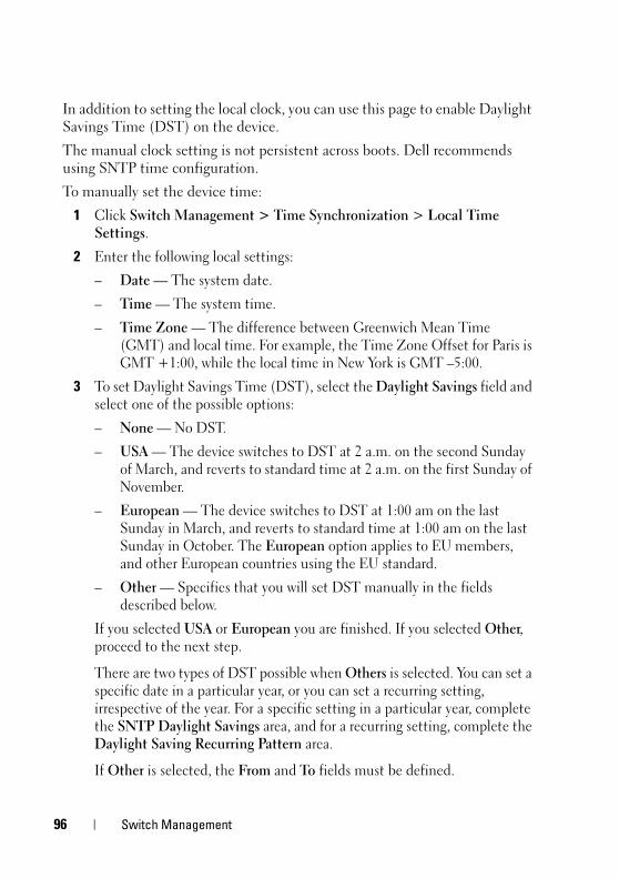
FILE LOCATION: C:\Users\vijaya_devakumar_dev\Documents\PowerConnect\Astute\Docs for Web Posting\Astute_Admin_Guide_sources_MIF7\FM\Dell_Astute_SwitchManagement.fm
D E L L C O N F I D E N T I A L – P R E L I M I N A R Y 3 / 1 9 / 1 5 - F O R P R O O F O N LY
In addition to setting the local clock, you can use this page to enable Daylight Savings Time (DST) on the device.
The manual clock setting is not persistent across boots. Dell recommends using SNTP time configuration.
To manually set the device time:
1 Click Switch Management > Time Synchronization > Local Time Settings.
2 Enter the following local settings:
– Date — The system date.
– Time — The system time.
– Time Zone — The difference between Greenwich Mean Time (GMT) and local time. For example, the Time Zone Offset for Paris is GMT +1:00, while the local time in New York is GMT –5:00.
3 To set Daylight Savings Time (DST), select the Daylight Savings field and select one of the possible options:
– None — No DST.
– USA — The device switches to DST at 2 a.m. on the second Sunday of March, and reverts to standard time at 2 a.m. on the first Sunday of November.
– European — The device switches to DST at 1:00 am on the last Sunday in March, and reverts to standard time at 1:00 am on the last Sunday in October. The European option applies to EU members, and other European countries using the EU standard.
– Other — Specifies that you will set DST manually in the fields described below.
If you selected USA or European you are finished. If you selected Other, proceed to the next step.
There are two types of DST possible when Others is selected. You can set a specific date in a particular year, or you can set a recurring setting, irrespective of the year. For a specific setting in a particular year, complete the SNTP Daylight Savings area, and for a recurring setting, complete the Daylight Saving Recurring Pattern area.
If Other is selected, the From and To fields must be defined.
96 Switch Management

FILE LOCATION: C:\Users\vijaya_devakumar_dev\Documents\PowerConnect\Astute\Docs for Web Posting\Astute_Admin_Guide_sources_MIF7\FM\Dell_Astute_SwitchManagement.fm
D E L L C O N F I D E N T I A L – P R E L I M I N A RY 3 / 1 9 / 1 5 - F O R P R O O F O N LY
4 To enter non-recurring DST parameters, enter the following fields:
– From — The time that DST begins. The possible options are:
• Day/Week/Month — The date at which DST begins.
• Time — The time (hour and minutes) at which DST begins.
– To — The time that DST ends. The possible options are:
• Day/Week/Month — The date at which DST ends.
• Time — The time (hour and minutes) at which DST ends.
5 To enter recurring DST parameters, select Daylight Saving Recurrence Patter and enter the following fields:
– From — The time that DST begins each year, for example, DST begins locally every second Sunday in April at 5:00 am. The possible options are:
• Day — The day of the week from which DST begins every year.
• Week — The week within the month from which DST begins every year.
• Month — The month of the year in which DST begins every year.
• Time — The time at which DST begins every year.
– To — The recurring time that DST ends each year, for example, DST ends locally every fourth Friday in October at 5:00 am. The possible options are:
• Day — The day of the week at which DST ends every year.
• Week — The week within the month at which DST ends every year.
• Month — The month of the year in which DST ends every year.
• Time — The time at which DST ends every year.
System Time from an SNTP ServerThis section describes how to configure SNTP servers. It contains the following topics:
• Overview
• SNTP Global Settings
• SNTP Authentication
Switch Management 97

FILE LOCATION: C:\Users\vijaya_devakumar_dev\Documents\PowerConnect\Astute\Docs for Web Posting\Astute_Admin_Guide_sources_MIF7\FM\Dell_Astute_SwitchManagement.fm
D E L L C O N F I D E N T I A L – P R E L I M I N A R Y 3 / 1 9 / 1 5 - F O R P R O O F O N LY
• SNTP Servers
• SNTP Interface Settings
Overview
The switch supports the Simple Network Time Protocol (SNTP), which provides accurate network switch clock time synchronization of up to 100 milliseconds. The implementation of SNTP is based on SNTPv4 (RFC 2030).
SNTP is a simple and lighter version of NTP, and can be used when the ultimate performance of the full NTP implementation, described in RFC-1305, is not required. SNTP operates with NTP, thus an SNTP client can work with both SNTP and NTP servers.
The switch operates only as a client, and cannot provide time services to other systems. SNTP Server Types
The switch can accept time information from the following server types:
• Unicast
Polling for Unicast information is used for polling a server whose IP address is known. This is the preferred method for synchronizing device time, as it is most secure.
Up to eight SNTP servers can be defined.
If this method is selected, SNTP information is accepted only from SNTP servers defined in the SNTP Servers page.
Time levels T1 - T4 (see the Algorithm for Selecting Designated SNTP Server section) are used to determine from which server time information is accepted.
If Unicast polling is not enabled or if no servers are defined on the device, the device accepts time information from any SNTP server of the type that is enabled, which responds.
• Anycast
Polling for Anycast information is used when the SNTP server’s IP address is not defined or it cannot be reached. If this method is enabled, time information can be received from any SNTP server on the network. The
98 Switch Management

FILE LOCATION: C:\Users\vijaya_devakumar_dev\Documents\PowerConnect\Astute\Docs for Web Posting\Astute_Admin_Guide_sources_MIF7\FM\Dell_Astute_SwitchManagement.fm
D E L L C O N F I D E N T I A L – P R E L I M I N A RY 3 / 1 9 / 1 5 - F O R P R O O F O N LY
device time and date are synchronized when it proactively requests synchronization information.
Anycast polling to get time information is preferable to Broadcast polling, because it is more secure.
Time levels T3 and T4 are used to determine from which server time information is accepted.
• Broadcast
Broadcast information is used if receiving Broadcast packets has been enabled, and one of the following situations occurs:
– The SNTP server IP address has not been defined.
– Several time-information packets are received and the Broadcast time is best according to the algorithm defined in Algorithm for Selecting Designated SNTP Server.
Broadcast is the least secure method of receiving time, because it is both unsecured and the time information was not specifically requested by the device. Anycast is also unsecured, but time-information packets are only accepted if they were requested.Stratums
Each SNTP server is characterized by stratums, which define the accuracy of its clock. The stratum is the distance, in terms of NTP hops, from the most authoritative time server. The lower the stratum (where zero is the lowest), the more accurate the clock. The switch accepts time from stratum 1 and above.
The following provides examples of clocks from various stratums:
• Stratum 0 — A real time clock is used as the time source, for example, a GPS system.
• Stratum 1 — A server that is directly linked to a Stratum 0 time source is used.
• Stratum 2 — The time source is distanced from the Stratum 1 server over a network path, for example, a Stratum 2 server receives the time over a network link, via NTP, from a Stratum 1 server.
Switch Management 99

1
FILE LOCATION: C:\Users\vijaya_devakumar_dev\Documents\PowerConnect\Astute\Docs for Web Posting\Astute_Admin_Guide_sources_MIF7\FM\Dell_Astute_SwitchManagement.fm
D E L L C O N F I D E N T I A L – P R E L I M I N A R Y 3 / 1 9 / 1 5 - F O R P R O O F O N LY
Algorithm for Selecting Designated SNTP Server
Messages received from SNTP servers are logged, until there are three responding servers, or the timer expires. In any event, when the third message is received, the timer expires.
A server is selected to be the “designated server” according to the following criteria:
• The stratum (the distance in terms of NTP hops from the best authoritative time servers) is considered, and the server with the best (lowest) stratum is selected.
• If there is a tie in stratums, packets from servers defined on the device are preferred to Anycast packets, which in turn are preferred to Broadcast packets.
• If multiple servers pass the above criteria, then the server that sent the first (earliest) time packet is chosen.
If a better server is discovered later, it is selected to be the “designated server” at that time.Polling
You can configure the system to acquire time information in the following ways:
• Enable polling — Time information is requested every polling interval.
• Do not enable polling — Time information is received when the system is brought up and every time that a topological change is made to the Running Configuration file, for example when an SNTP Unicast server is added.
This is configured by the user in the SNTP Global Settings page.
On power up, when the switch sends a request and there is no reply, it issues another request (three retries at most) after 20 seconds of waiting.
If no SNTP server is found, the process is invoked every “poll interval” (set in the SNTP Global Settings page), and a management trap is triggered.Authentication
You can require that SNTP servers be authenticated, although this is not mandatory (see the SNTP Authentication page).
00 Switch Management

FILE LOCATION: C:\Users\vijaya_devakumar_dev\Documents\PowerConnect\Astute\Docs for Web Posting\Astute_Admin_Guide_sources_MIF7\FM\Dell_Astute_SwitchManagement.fm
D E L L C O N F I D E N T I A L – P R E L I M I N A RY 3 / 1 9 / 1 5 - F O R P R O O F O N LY
MD5 (Message Digest 5) Authentication safeguards device synchronization paths to SNTP servers. MD5 is an algorithm that produces a 128-bit hash value. MD5 is a variation of MD4, and increases MD4 security.
MD5 both verifies the integrity of the communication and authenticates the origin of the communication.
SNTP Global Settings
If SNTP was selected as the clock source in the SNTP Global Settings page, you must define the mechanism of setting time from an SNTP server. This is done in the SNTP Servers pages, described below.
To define the types of server from which the device accepts SNTP information and the polling interval:
1 Click Switch Management > Time Synchronization > SNTP Global Settings.
2 Enter the fields:
– Poll Interval (Sec.) — Enter the interval (in seconds) at which the SNTP servers are polled.
– Receive Broadcast Servers Updates — Enable/disable receiving time information from Broadcast servers.
– Receive Anycast Servers Updates — Enable/disable receiving time information from Anycast SNTP servers.
– Receive Unicast Servers Updates — Enable/disable receiving time information from the SNTP servers defined on the switch.
– Poll Unicast Requests — Enable/disable sending SNTP Unicast server time information requests to the SNTP server.
SNTP Authentication
Use the SNTP Authentication page to enable/disable SNTP authentication between the device and an SNTP server, and to set the means by which the SNTP server is authenticated.
To configure SNTP authentication:
1 Click Switch Management > Time Synchronization > SNTP Authentication.
The previously-defined authentication keys are displayed.
Switch Management 101

1
FILE LOCATION: C:\Users\vijaya_devakumar_dev\Documents\PowerConnect\Astute\Docs for Web Posting\Astute_Admin_Guide_sources_MIF7\FM\Dell_Astute_SwitchManagement.fm
D E L L C O N F I D E N T I A L – P R E L I M I N A R Y 3 / 1 9 / 1 5 - F O R P R O O F O N LY
2 Enable/disable SNTP Authentication. This enables/disables authenticating SNTP sessions between the device and an SNTP server.
3 Multiple keys can be defined. To add a new SNTP authentication key, click Edit, Add, and enter the fields.
– Encryption Key ID — Enter the number used to identify this SNTP authentication key internally.
– Authentication Key — Enter the key used for authentication. The SNTP server must send this key for the switch to use its time and date information.
– Trusted Key — Check to specify that the encryption key is used to authenticate the (Unicast) SNTP server. If this is not checked, the key is not used for authentication (and another key(s) is used).
SNTP Servers
To add an SNTP server or display SNTP server information:
1 Click Switch Management > Time Synchronization > SNTP Servers.
The following is displayed for the previously-defined servers:
– SNTP Server — IP address of server.
– Polling — Polls the selected SNTP server for system time information, when enabled.
– Encryption Key ID — Key Identification used to communicate between the SNTP server and device.
– Preference — SNTP server providing SNTP system time information. The system displays on of the following options:
• Primary — The server from which time was last accepted.
• Secondary — All other servers from which time was received.
– Status — The operating SNTP server status. The possible options are:
• Up — The SNTP server is currently operating normally.
• Down — An SNTP server is currently not available, for example, the SNTP server is currently not connected or is currently down.
• In progress — The SNTP server is currently sending or receiving SNTP information.
02 Switch Management

FILE LOCATION: C:\Users\vijaya_devakumar_dev\Documents\PowerConnect\Astute\Docs for Web Posting\Astute_Admin_Guide_sources_MIF7\FM\Dell_Astute_SwitchManagement.fm
D E L L C O N F I D E N T I A L – P R E L I M I N A RY 3 / 1 9 / 1 5 - F O R P R O O F O N LY
• Unknown — The progress of the SNTP information currently being sent is unknown, for example, the device is currently looking for an interface.
– Last Response — The last time a response was received from the SNTP server.
– Offset — The estimated offset of the server's clock, relative to the local clock, in milliseconds. The host determines the value of this offset, using the algorithm described in RFC 2030.
– Delay — The estimated round-trip delay of the server's clock, relative to the local clock over the network path between them, in milliseconds. The host determines the value of this delay, using the algorithm described in RFC 2030.
2 To add an SNTP Server, click Add, and enter the fields:
– Supported IP Format — Select whether IPv4 or IPv6 format is used for the IP address of the SNTP server.
– IPv6 Address Type — When the server supports IPv6, this specifies the type of static address supported. Select one of the possible options:
• Link Local — A Link Local address that is non-routable and used for communication on the same network only.
• Global — A globally unique IPv6 address; visible and reachable from different subnets.
– SNTP Server — Enter the SNTP server’s IP address.
– Polling — Enable/disable polling the selected SNTP server for system time information, when enabled.
– Encryption Key ID — Check to use an encryption key, and select one of the encryption keys that was defined in the SNTP Authentication pages.
SNTP Interface Settings
If receiving time information from Anycast servers is enabled, you can determine through which interface the Anycast packets are sent and received. If no interface is defined, Anycast requests are not sent.
Switch Management 103

1
FILE LOCATION: C:\Users\vijaya_devakumar_dev\Documents\PowerConnect\Astute\Docs for Web Posting\Astute_Admin_Guide_sources_MIF7\FM\Dell_Astute_SwitchManagement.fm
D E L L C O N F I D E N T I A L – P R E L I M I N A R Y 3 / 1 9 / 1 5 - F O R P R O O F O N LY
To enable receiving Anycast updates on an interface:
1 Click Switch Management > Time Synchronization > SNTP Interface Settings.
The following fields are displayed for every interface for which an SNTP interface has been enabled:
– Interface — The port, LAG or VLAN on which SNTP is enabled.
– Receive Servers Updates — Displays whether the interface is enabled to receive updates from the SNTP server.
2 To add an interface that can receive SNTP server updates, click Edit, Add.
3 Enter the following fields:
– Interface Type — Type of interface on which SNTP is being configured.
– Interface — Interface on which SNTP is being configured.
Management SecurityThis section describes the pages used to manage device security.
It contains the following topics:
• Global Password Management
• Line Password for CLI
• Enable Password for CLI
• Active Users
• Local User Database
• Access Profiles and Rules Configuration
• Authentication Profiles
• Select Authentication
• TACACS+
• RADIUS
04 Switch Management

FILE LOCATION: C:\Users\vijaya_devakumar_dev\Documents\PowerConnect\Astute\Docs for Web Posting\Astute_Admin_Guide_sources_MIF7\FM\Dell_Astute_SwitchManagement.fm
D E L L C O N F I D E N T I A L – P R E L I M I N A RY 3 / 1 9 / 1 5 - F O R P R O O F O N LY
Global Password Management Password management provides increased network security and improved password control. This feature is optional and must be enabled in the Global Password Management page.
Passwords for Telnet, Secure Telnet (SSH) and console access can be assigned security features that include:
• Number of repeated characters allowed
• Minimum password lengths
• Password expiration dates (password aging)
• Prevention of frequent password reuse
• Lockout of users after failed login attempts
• Number of different character classes required in the password. Numeric, alphabetic, and special characters are all character classes.
• Length of time that past passwords are stored.
Password aging starts immediately after password management is enabled. However it is only effective if system time on the device is taken from an SNTP server. Passwords expire according to the user-defined expiration date/time. Ten days prior to password expiration, the device displays a password expiration warning message.
After the password has expired, users can log in a few additional times. During the remaining logins, an additional warning message displays informing the user that the password must be changed. If the password is not changed, users are locked out of the system, and can only log in using the console. Password warnings are logged in the SYSLOG file.
NOTE: Password aging is enabled only after setting the switch to use SNTP for setting time.
To define password management parameters:
1 Click Switch Management > Management Security > Global Password Management.
2 Click Edit to check the required fields and enter their values:
– Enable Strong Passwords — Check to enable this feature.
– Repeated Characters — Select the number of permissible repeated characters in the password.
Switch Management 105

1
FILE LOCATION: C:\Users\vijaya_devakumar_dev\Documents\PowerConnect\Astute\Docs for Web Posting\Astute_Admin_Guide_sources_MIF7\FM\Dell_Astute_SwitchManagement.fm
D E L L C O N F I D E N T I A L – P R E L I M I N A R Y 3 / 1 9 / 1 5 - F O R P R O O F O N LY
– Password Minimum Length — When checked, specifies the minimum password length. Enter the minimum password length.
– Enable Login Attempts — When checked, enables locking a user out of the device when a faulty password is used more than the number of times entered. Select the maximum number of login attempts.
– Global Password Aging — When checked, specifies that the password will expire in the number of days entered. Enter the number of days. This is only enabled after setting the switch to use SNTP for setting time
– Consecutive Passwords Before Reuse — When checked, indicates the number of times a password must be changed, before the password can be reused. Select the number of times.
– Password History Hold Time — When checked, the password history will be deleted after the number of days entered. Enter the number of days.
Line Password for CLI To add a line password for Console, Telnet, and Secure-Telnet users:
1 Click Switch Management > Management Security > Line Password for CLI.
2 Click Edit to enter the fields for each type of user, separately:
– Password — Enter the line password for accessing the device.
– Confirm Password — Confirm the line password.
– Expiry Date — Displays the expiration date of the line password.
– Lockout Status — Displays whether the user currently has access (status Usable), or whether the user is locked out due to too many failed authentication attempts since the user last logged in successfully (status Locked).
– Reactivate Locked Line — Check to reactivate the line password for a Console/Telnet/Secure Telnet session. Access rights can be suspended after a number of unsuccessful attempts to log in.
Enable Password for CLI
NOTE: CLI is only available in unmanaged mode.
06 Switch Management
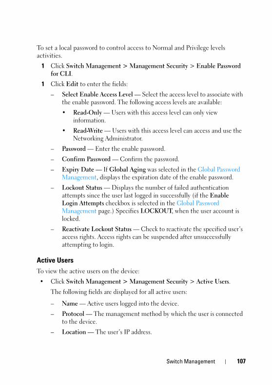
FILE LOCATION: C:\Users\vijaya_devakumar_dev\Documents\PowerConnect\Astute\Docs for Web Posting\Astute_Admin_Guide_sources_MIF7\FM\Dell_Astute_SwitchManagement.fm
D E L L C O N F I D E N T I A L – P R E L I M I N A RY 3 / 1 9 / 1 5 - F O R P R O O F O N LY
To set a local password to control access to Normal and Privilege levels activities.
1 Click Switch Management > Management Security > Enable Password for CLI.
1 Click Edit to enter the fields:
– Select Enable Access Level — Select the access level to associate with the enable password. The following access levels are available:
• Read-Only — Users with this access level can only view information.
• Read-Write — Users with this access level can access and use the Networking Administrator.
– Password — Enter the enable password.
– Confirm Password — Confirm the password.
– Expiry Date — If Global Aging was selected in the Global Password Management, displays the expiration date of the enable password.
– Lockout Status — Displays the number of failed authentication attempts since the user last logged in successfully (if the Enable Login Attempts checkbox is selected in the Global Password Management page.) Specifies LOCKOUT, when the user account is locked.
– Reactivate Lockout Status — Check to reactivate the specified user’s access rights. Access rights can be suspended after unsuccessfully attempting to login.
Active Users To view the active users on the device:
• Click Switch Management > Management Security > Active Users.
The following fields are displayed for all active users:
– Name — Active users logged into the device.
– Protocol — The management method by which the user is connected to the device.
– Location — The user’s IP address.
Switch Management 107

1
FILE LOCATION: C:\Users\vijaya_devakumar_dev\Documents\PowerConnect\Astute\Docs for Web Posting\Astute_Admin_Guide_sources_MIF7\FM\Dell_Astute_SwitchManagement.fm
D E L L C O N F I D E N T I A L – P R E L I M I N A R Y 3 / 1 9 / 1 5 - F O R P R O O F O N LY
Local User Database
Use the Local User Database page to define users, passwords and access levels.
The default username is admin. There is no default password.
To add a new user:
1 Click Switch Management > Management Security > Local User Database.
All users are displayed even if they have been suspended. The following fields are displayed:
• Expiry Date — The expiration date of the user-defined password.
• Lockout Status — Specifies whether the user currently has access (status Usable), or whether the user is locked out due to too many failed authentication attempts since the user last logged in successfully (status Locked).
• Reactivate Suspended User — Check to reactivate the specified user’s access rights. Access rights can be suspended after unsuccessfully attempting to login.
If a user has been suspended, it can be restored here by selecting the Reactivate Suspended User field.
2 To add a user, click Edit and then Add, and enter the fields:
– User Name (1-20 characters) — Enter the username of the user.
– Access Level — Select a user access level. The lowest user access level is 1 Read-Only and 15 Read-Write is the highest user access level. Users with access level 15 are Privileged Users, and only they can access and use the switch administrator.
– Password (8-64 characters) — Enter the password of the user.
– Confirm Password — Confirm the password of the user.
Access Profiles and Rules ConfigurationAccess to management functions can be limited to users identified by:
• Ingress interface (Port, LAG, or VLAN)
• Source IP address
08 Switch Management

FILE LOCATION: C:\Users\vijaya_devakumar_dev\Documents\PowerConnect\Astute\Docs for Web Posting\Astute_Admin_Guide_sources_MIF7\FM\Dell_Astute_SwitchManagement.fm
D E L L C O N F I D E N T I A L – P R E L I M I N A RY 3 / 1 9 / 1 5 - F O R P R O O F O N LY
• Source IP subnet
Management access can be separately defined for the following types of management access methods:
• Telnet (CLI over Telnet sessions)
• Secure Telnet (SSH)
• Web (HTTP)
• Secure Web (HTTPS)
• SNMP
This means, for example, that the set of managers allowed via Telnet may be different than the set of Web-based managers which is, in turn, may be different than the set of secure-web based managers, and so on.
A specific management access method may be completely disabled by denying all user access to it (e.g. denying all users access to CLI/Telnet management effectively disables CLI/Telnet as an available management interface to the system).
By default, management access to the system, through all methods, is enabled over all interfaces.
NOTE: If you enable management access on certain types of interfaces, the following holds:.
• Physical Port — All VLANs and IP interfaces on this port are acceptable management traffic sources.
• VLAN — All ports and IP interfaces on that VLAN will be acceptable.
• Specific IP Address — Only traffic from these specified IP addresses on the appropriate ports are accepted.
Access Profiles and Rules
A management access profile is composed of at least one rule, which acts as a filter, and defines the device management method, interface type, source IP address, network mask, and the profile action.
Users can be blocked or permitted management access by these access profiles.
Switch Management 109

1
FILE LOCATION: C:\Users\vijaya_devakumar_dev\Documents\PowerConnect\Astute\Docs for Web Posting\Astute_Admin_Guide_sources_MIF7\FM\Dell_Astute_SwitchManagement.fm
D E L L C O N F I D E N T I A L – P R E L I M I N A R Y 3 / 1 9 / 1 5 - F O R P R O O F O N LY
Rule priority sets the order in which the rules are implemented. Assigning an access profile to an interface denies access via other interfaces. If an access profile is not assigned to any interface, the device can be accessed by all interfaces.
A total of 256 rules can be defined for all Management Access profiles.
Common actions are:
• Adding an access profile with a single rule
• To activate a profile
Adding an access profile with a single rule
1 Click Switch Management > Management Security > Access Profiles and Rules.
The currently-defined access profiles are displayed.
2 Click Edit, Add and enter the fields:
– Access Profile Name — Select a profile to add a rule to a previously-created profile or select New Profile to create a new profile.
– Access Profile Name — Enter a name for a new access profile if New Profile was selected above.
– Rule Priority — Enter the rule priority. Rules are applied to packets according to their priority.
– Management Method — Select the management method to which the access profile is applied. Users using this management method are authenticated using this access profile. The possible options are:
• All — The access profile is applied to all management methods.
• Telnet — The access profile is applied to Telnet users.
• SNMP— The access profile is applied to SNMP users.
• HTTP — The access profile is applied to HTTP users.
• Secure HTTP (HTTPS) — The access profile is applied to HTTPS users.
• Secure Telnet (SSH) — The access profile is applied to SSH users.
– Interface Type — Check the interface type to which the rule applies. See note above.
10 Switch Management

FILE LOCATION: C:\Users\vijaya_devakumar_dev\Documents\PowerConnect\Astute\Docs for Web Posting\Astute_Admin_Guide_sources_MIF7\FM\Dell_Astute_SwitchManagement.fm
D E L L C O N F I D E N T I A L – P R E L I M I N A RY 3 / 1 9 / 1 5 - F O R P R O O F O N LY
– Interface — Select the specific interface to which the rule applies.
– Source IP Address — Select Enable/Disable to allow or not allow access, restriction based on the source IP address. When this field is disabled, the source IP address cannot be entered into a configured rule.
– Supported IP Format — Select whether the IPv4 or IPv6 format is supported for the source IP addresses.
– IP Address — Enter the interface source IP address for which the rule applies. This is an optional field and indicates that the rule is valid for a subnetwork.
– Address Class — Select one of the following options:
• Subnet Mask — Enter the IP subnetwork mask if Supported IP Format is IPv4.
• Prefix Length — Enter the number of bits that comprise the source IP address prefix, or the network mask of the source IP address.
– Subnet Mask — Enter the subnet mask of the IP address of the device.
– Prefix Length — Enter the number of bits that comprise the IP address prefix of the subnetwork.
– Action — Select whether to permit or deny management access to the defined interface. The possible options are:
• Permit — Permits access to the device.
• Deny — Denies access to the device.
To activate a profile
1 Click Switch Management > Management Security > Access Profiles and Rules.
The currently-defined access profiles are displayed.
2 To activate an access profile, select it in the Active Access Profile field.
3 Click Edit, Settings Icon ( ).
Switch Management 111

1
FILE LOCATION: C:\Users\vijaya_devakumar_dev\Documents\PowerConnect\Astute\Docs for Web Posting\Astute_Admin_Guide_sources_MIF7\FM\Dell_Astute_SwitchManagement.fm
D E L L C O N F I D E N T I A L – P R E L I M I N A R Y 3 / 1 9 / 1 5 - F O R P R O O F O N LY
NOTE: The following apply:
• If you select Console Only, active management of the device can only be performed using the console connection. In this case, you are disconnected from the management GUI. This profile cannot be removed.
• If you select None, access is available to all.
Authentication Profiles In addition to access profiles, you can configure authentication for either the console or network management access method.
For these access methods, user authentication can occur:
• Locally
• Via an external server, such as a TACACS+ or a RADIUS server
User authentication occurs in the order that the methods are selected, for example, if both the Local and RADIUS options are selected, the user is authenticated first locally. If the local user database is empty, the user is authenticated via the RADIUS server.
If an error occurs during the authentication, the next selected method is used.
If an authentication method fails, or the user has an insufficient privilege level, the user is denied access to the switch. The switch then stops, does not continue, and does not attempt to use the next authentication method.
User authentication can also be set to None, in which case no authentication is performed.
The process of configuring authentication for management access methods is divided into the following stages:
• Create an authentication profile, as described below
• Assign an authentication profile to a management method, as described in Select Authentication
To create an authentication profile:
1 Click Switch Management > Management Security > Authentication Profiles.
All currently-defined authentication profiles are displayed.
12 Switch Management

FILE LOCATION: C:\Users\vijaya_devakumar_dev\Documents\PowerConnect\Astute\Docs for Web Posting\Astute_Admin_Guide_sources_MIF7\FM\Dell_Astute_SwitchManagement.fm
D E L L C O N F I D E N T I A L – P R E L I M I N A RY 3 / 1 9 / 1 5 - F O R P R O O F O N LY
2 Click Edit, Add to add a new authentication profile, and enter the fields:
– Authentication Profile Name (1-12 Characters) — Enter the name of the new authentication profile. Profile names cannot include blank spaces.
– Optional Methods — Select a user authentication methods that can be assigned to this authentication profile. The possible options are:
• Line — The line password is used for user authentication (defined in Line Password for CLI).
• Enable — The enable (encrypted) password is used for authentication (defined in Enable Password for CLI).
• Local — The user authentication is performed by the device, which checks the user name and password for authentication.
• RADIUS — The user authentication is performed by the RADIUS server. For more information, see RADIUS.
• TACACS+ — The user authentication is performed by the TACACS+ server. For more information, see TACACS+.
• None — No user authentication occurs.
Select a method by highlighting it in the Optional Methods list, and clicking on the right arrow to move it to the Selected Methods list.
Select Authentication After authentication profiles are defined, they can be assigned to management access methods, for example, console users can be authenticated by Console, while Telnet users can be authenticated by Network Default.
To assign an authentication profile to a management access method:
1 Click Switch Management > Management Security > Select Authentication.
2 For the Console, Telnet and Secure Telnet (SSH) types of users, select either the default authentication profile or one of the previously-defined authentication profiles.
Switch Management 113

1
FILE LOCATION: C:\Users\vijaya_devakumar_dev\Documents\PowerConnect\Astute\Docs for Web Posting\Astute_Admin_Guide_sources_MIF7\FM\Dell_Astute_SwitchManagement.fm
D E L L C O N F I D E N T I A L – P R E L I M I N A R Y 3 / 1 9 / 1 5 - F O R P R O O F O N LY
3 For Secure HTTP and HTTP types of users, select one or all of the Optional Methods and click the right-arrow to move them to the Selected Methods. The options are:
– Local — Authentication occurs locally.
– None — No authentication method is used for access.
– RADIUS — Authentication occurs at the RADIUS server.
– TACACS+ — Authentication occurs at the TACACS+ server.
TACACS+ The device can act as a Terminal Access Controller Access Control System (TACACS+) client. TACACS+ provides centralized validation of users accessing the device, while still retaining consistency with RADIUS and other authentication processes.
TACACS+ provides the following services:
• Authentication — Provides authentication during login and via user names and user-defined passwords.
• Authorization — Performed at login after authentication. The TACACS+ server checks the privileges of the authenticated user.
The TACACS+ protocol ensures network integrity through encrypted protocol exchanges between the device and TACACS+ server.
To configure TACACS+ servers:
1 Click Switch Management > Management Security > TACACS+.
The list of currently-defined TACACS+ servers is displayed. The parameters for each server is displayed, along with its connection status.
2 To set the global parameters, click Edit, Settings Icon ( ) and enter the following fields:
– Source IPv4 Interface — Enter the address of the IPv4 interface used to connect to the TACACS server.
– Source IPv6 Interface — Enter the address of the IPv6 interface used to connect to the TACACS server.
– Key String — Enter the key of the TACACS+ server.
14 Switch Management

FILE LOCATION: C:\Users\vijaya_devakumar_dev\Documents\PowerConnect\Astute\Docs for Web Posting\Astute_Admin_Guide_sources_MIF7\FM\Dell_Astute_SwitchManagement.fm
D E L L C O N F I D E N T I A L – P R E L I M I N A RY 3 / 1 9 / 1 5 - F O R P R O O F O N LY
– Timeout for Replay — Enter the amount of time that can pass before the connection between the device and the TACACS+ server times out.
3 To add a TACACS+ server, click Edit, Add and enter the following fields:
– Supported IP Format — Select whether the IPv4 or IPv6 format is supported for the TACACS+ server IP address.
– IPv6 Address Type — Select whether the Link-Local or Global format of the IPv6 Address is supported for the TACACS+ server IP address.
– Host IP Address — Enter the TACACS+ server IP address.
– Priority — Enter the order in which the TACACS+ servers are used if several are defined.
– Authentication Port — Enter the port number through which the TACACS+ session occurs.
– Key String — Enter the key of the TACACS+ server or select Use Default.
– Timeout for Reply (sec) — Enter the amount of time that can pass before the connection between the device and the TACACS+ server times out or select Use Default.
– Single Connection — Select Enable to maintain a single open connection between the device and the TACACS+ server or Disable not to maintain a connection.
RADIUS Remote Authentication Dial-In User Service (RADIUS) servers provide additional security for networks. Up to eight RADIUS servers can be defined.
RADIUS servers provide a centralized authentication method for:
• Telnet Access
• Secure Shell Access
• Web Access
• Console Access
Switch Management 115

1
FILE LOCATION: C:\Users\vijaya_devakumar_dev\Documents\PowerConnect\Astute\Docs for Web Posting\Astute_Admin_Guide_sources_MIF7\FM\Dell_Astute_SwitchManagement.fm
D E L L C O N F I D E N T I A L – P R E L I M I N A R Y 3 / 1 9 / 1 5 - F O R P R O O F O N LY
To add a RADIUS server:
1 Click Switch Management > Management Security > RADIUS.
The RADIUS default parameters and previously-defined RADIUS servers are displayed.
2 To set the global parameters, click Edit, Settings Icon ( ) and enter the following fields:
– Source IPv4 Interface — Enter the address of the IPv4 interface used to connect to the RADIUS server.
– Source IPv6 Interface — Enter the address of the IPv6 interface used to connect to the RADIUS server.
– Key String — Enter the key of the TACACS+ server.
– Timeout for Replay — Enter the amount of time that can pass before the connection between the device and the TACACS+ server times out.
– Number of Retries — Enter the number of requests sent to the RADIUS server before a failure occurs.
– Dead Time (sec) — The amount of time (in minutes) that a RADIUS server is bypassed for service requests.
3 To add a RADIUS server, click Edit, Add, and enter the fields:
– Supported IP Format — Select whether the IPv4 or IPv6 format is supported.
– IPv6 Address Type — Select whether the Link-Local or Global format of the IPv6 Address is supported.
– Host IP Address — Enter the RADIUS server IP address.
– Priority — Enter the priority of the RADIUS server being added. 0 is the highest value. This is used to configure the order in which servers are queried.
– Authentication Port — Enter the authentication port used to verify the RADIUS server authentication. Enter 0 if you do not want this server to be used for authentication purposes.
– Accounting Port — Enter the accounting port, which is the UDP port number of the RADIUS server used for accounting requests. Enter 0 if you do not want this server to be used for accounting purposes.
16 Switch Management

FILE LOCATION: C:\Users\vijaya_devakumar_dev\Documents\PowerConnect\Astute\Docs for Web Posting\Astute_Admin_Guide_sources_MIF7\FM\Dell_Astute_SwitchManagement.fm
D E L L C O N F I D E N T I A L – P R E L I M I N A RY 3 / 1 9 / 1 5 - F O R P R O O F O N LY
– Key String — The key string used for authenticating and encrypting all RADIUS communications between the device and the RADIUS server. Select Use Default to use the default value.
– Number of Retries — Enter the number of requests sent to the RADIUS server before a failure occurs. Select Use Default to use the default value.
– Timeout for Reply — The amount of the time in seconds that the device waits for an answer from the RADIUS server before retrying the query, or switching to the next server. Select Use Default to use the default value.
– Dead Time — The amount of time (in minutes) that a RADIUS server is bypassed for service requests. Select Use Default to use the default value.
– Usage Type — Enter the RADIUS server usage. The possible options are:
• Login — Used for login authentication and/or accounting.
• 802.1x — Used for 802.1x authentication and/or accounting.
• All — Used for all types of authentication and/or accounting.
Switch Management 117

1
FILE LOCATION: C:\Users\vijaya_devakumar_dev\Documents\PowerConnect\Astute\Docs for Web Posting\Astute_Admin_Guide_sources_MIF7\FM\Dell_Astute_SwitchManagement.fm
D E L L C O N F I D E N T I A L – P R E L I M I N A R Y 3 / 1 9 / 1 5 - F O R P R O O F O N LY
18 Switch Management

D E L L C O N F I D E N T I A L – P R E L I M I N A RY 3 / 1 9 / 1 5 - F O R P R O O F O N LY
7Logs and AlertsThe Logs feature enables the switch to keep several, independent logs. Each log is a set of entries that record system events.
It contains the following topics:
• Overview
• Logs
• Login History
• Remote Log Servers
OverviewSystem logs record events and report errors or informational messages. Some aspects of system logging can be configured, as described below.
The following types of log messages can be generated:
• Urgent — If the device is down or not functioning properly, an urgent log message is generated. Urgent messages include emergency, alert and critical level messages.
• Major — An alert log is saved if there is a serious device malfunction, for example, all device features are down. Major messages include error and warning level messages.
• Information — Provides device information to which you do not have to respond. Information messages include notice and informational level messages.
• Debug — Provides debugging messages.
Some events are automatically logged, such as hardware problems. You may enable/disable logging of events in the Logs page and logins in the Login History page.
Template Last Updated - 2010 Logs and Alerts 119

1
FILE LOCATION: C:\Users\vijaya_devakumar_dev\Documents\PowerConnect\Astute\Docs for Web Posting\Astute_Admin_Guide_sources_MIF7\FM\Dell_Astute_Logs&Alerts.fm
D E L L C O N F I D E N T I A L – P R E L I M I N A R Y 3 / 1 9 / 1 5 - F O R P R O O F O N LY
Event messages have a unique format, as per the System Logs (SYSLOG) protocol recommended message format for all error reporting, for example, SYSLOG and local device reporting messages are assigned a severity code, and include a message mnemonic that identifies the source application generating the message.
Messages may be filtered, based on their urgency or relevancy.
Events may be logged to the following destinations:
• Console
• Logging buffer (RAM)— Messages are stored in a cyclical file buffer. When the maximum number of messages is reached, messages are written starting at the beginning of the buffer (overwriting the old messages).
Logs stored on the Logging buffer are deleted when the device is reset.
• Logging file (flash) — Messages are stored in flash memory. When the buffer is full, messages are written starting at the beginning of the memory block (overwriting the old messages).
• SYSLOG Server — Messages are sent to a remote server. This is useful for central and remote management and to provide more space for storage of messages. Up-to eight SYSLOG servers can be defined in the Remote Log Servers page.
You can select where to send logging messages according to their severity. Each of the severity level can be directed to the console, RAM log, flash log file or SYSLOG server or to any combination of these destinations.
LogsUse the Logs page to configure logging on the device.
If you enable logging, some events are automatically logged, and in addition, you can enable/disable specific types of logging to various destinations.
To configure logging:
1 Click Logs and Alerts > Logs.
2 Click Edit, Settings Icon ( ).
3 Enable/disable logging in the following fields:
– Logging — Enables logging on the device.
20 Logs and Alerts

FILE LOCATION: C:\Users\vijaya_devakumar_dev\Documents\PowerConnect\Astute\Docs for Web Posting\Astute_Admin_Guide_sources_MIF7\FM\Dell_Astute_Logs&Alerts.fm
D E L L C O N F I D E N T I A L – P R E L I M I N A RY 3 / 1 9 / 1 5 - F O R P R O O F O N LY
– Log Authentication Events — Enable/disable generating logs when users are authenticated.
– Log Copy Files Events — Enable/disable generating logs when files are copied.
– Log Management Access Events — Enable/disable generating logs when the device is accessed using a management method, for example, each time the device is accessed using SSH, a device log is generated.
4 To select the destination of logging messages, according to their severity levels, check the minimum severity level that will be associated with the console log, RAM log and Log file (Flash memory). When a severity level is selected, all severity levels above the selection are selected automatically.
Login HistoryUse the Login History page to monitor users, including the time a user logged in, and the protocol used to log on to the device.
To enable user history logging:
1 Click Logs and Alerts > Login History.
The login history for the selected user or all users is displayed.
2 Click Edit, Settings Icon ( ).
3 Enable/disable Login History to File to record login history.
Remote Log ServersLog messages can be sent to remote log servers, using the SYSLOG protocol.
To add a remote log server:
1 Click Logs and Alerts > Remote Log Servers.
The previously-defined remote servers are displayed.
2 Click Edit, Add, and enter the fields:
– Supported IP Format — Select whether the IPv4 or IPv6 format is supported.
Logs and Alerts 121

1
FILE LOCATION: C:\Users\vijaya_devakumar_dev\Documents\PowerConnect\Astute\Docs for Web Posting\Astute_Admin_Guide_sources_MIF7\FM\Dell_Astute_Logs&Alerts.fm
D E L L C O N F I D E N T I A L – P R E L I M I N A R Y 3 / 1 9 / 1 5 - F O R P R O O F O N LY
– IPv6 Address Type — When the server supports IPv6, this specifies the type of static address supported. The possible options are:
• Link Local — A Link Local address that is non-routable and used for communication on the same network only.
• Global — A globally unique IPv6 address; visible and reachable from different subnets.
– Log Server IP Address — Enter the IP address of the remote SYSLOG server.
– Server Description — Enter a server description.
– UDP Port — Enter the UDP port to which the logs are sent for the selected server.
– Facility — Select a user-defined application from which system logs are sent to the remote server. Only a single facility can be assigned to a single server. If a second facility level is assigned, the first facility level is overridden. All applications defined for a device utilize the same facility on a server.
– Severity to Include — Check the severity levels to be logged to the remote server. The event severity levels are listed on this page in descending order from the highest severity to the lowest. When a severity level is selected to appear in a log, all higher severity events are automatically selected to appear in the log. When a security level is not selected, no lower severity events appear in the log.
22 Logs and Alerts
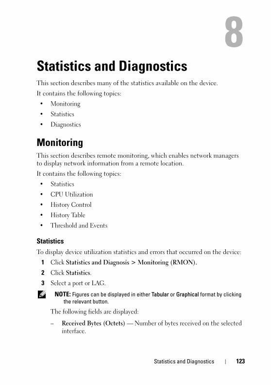
D E L L C O N F I D E N T I A L – P R E L I M I N A RY 3 / 1 9 / 1 5 - F O R P R O O F O N LY
8Statistics and DiagnosticsThis section describes many of the statistics available on the device.
It contains the following topics:
• Monitoring
• Statistics
• Diagnostics
MonitoringThis section describes remote monitoring, which enables network managers to display network information from a remote location.
It contains the following topics:
• Statistics
• CPU Utilization
• History Control
• History Table
• Threshold and Events
StatisticsTo display device utilization statistics and errors that occurred on the device:
1 Click Statistics and Diagnosis > Monitoring (RMON).
2 Click Statistics.
3 Select a port or LAG.
NOTE: Figures can be displayed in either Tabular or Graphical format by clicking the relevant button.
The following fields are displayed:
– Received Bytes (Octets) — Number of bytes received on the selected interface.
Template Last Updated - 2010 Statistics and Diagnostics 123

1
FILE LOCATION: C:\Users\vijaya_devakumar_dev\Documents\PowerConnect\Astute\Docs for Web
D E L L C O N F I D E N T I A L – P R E L I M I N A R Y 3 / 1 9 / 1 5 - F O R P R O O F O N LY
– Received Packets — Number of packets received on the selected interface.
– Broadcast Packets Received — Number of good Broadcast packets received on the interface since the device was last refreshed. This number does not include Multicast packets.
– Multicast Packets Received — Number of good Multicast packets received on the interface, since the device was last refreshed.
– CRC Align Error — Number of packets received with a length (excluding framing bits, but including FCS octets) of between 64 and 1518 octets, inclusive, but with either a bad Frame Check Sequence (FCS) with an integral number of octets (FCS Error) or a bad FCS with a non-integral number of octets (Alignment Error).
– Undersize Packets — Number of packets received, less than 64 octets long (excluding framing bits, but including FCS octets), and otherwise well formed.
– Oversize Packets — Number of packets received, longer than 1518 octets (excluding framing bits, but including FCS octets), and otherwise well formed.
– Fragments — Number of packets received, less than 64 octets in length (excluding framing bits but including FCS octets), which has either a bad Frame Check Sequence (FCS) with an integral number of octets (FCS Error), or a bad FCS with a non-integral number of octets (Alignment Error).
– Jabbers — Number of packets received, longer than 1518 octets (excluding framing bits, but including FCS octets), and having either a bad Frame Check Sequence (FCS) with an integral number of octets (FCS Error), or a bad FCS with a non-integral number of octets (Alignment Error).
– Collisions — Number of collisions received on the interface, since the device was last refreshed.
– Frames of 64 Bytes — Number of 64-byte frames received on the interface, since the device was last refreshed.
– Frames of 65 to 127 Bytes — Number of 65-127-byte frames received on the interface, since the device was last refreshed.
24 Statistics and Diagnostics

FILE LOCATION: C:\Users\vijaya_devakumar_dev\Documents\PowerConnect\Astute\Docs for Web
D E L L C O N F I D E N T I A L – P R E L I M I N A RY 3 / 1 9 / 1 5 - F O R P R O O F O N LY
– Frames of 128 to 255 Bytes — Number of 128-255-byte frames received on the interface, since the device was last refreshed.
– Frames of 256 to 511 Bytes — Number of 256-511-byte frames received on the interface, since the device was last refreshed.
– Frames of 512 to 1023 Bytes — Number of 512-1023-byte frames received on the interface, since the device was last refreshed.
– Frames of 1024 to Max Octets — Number of 1024-Max Octet frames received on the interface, since the device was last refreshed.
4 Select one of the Refresh Rate options to specify how frequently the statistics should be refreshed.
5 Select Reset All Counters to clear the counters.
CPU UtilizationUse the CPU Utilization page to display interface utilization. This page is refreshed periodically to minimize impact on performance. Display may be disrupted during this period.
To display interface utilization statistics:
1 Click Statistics and Diagnosis > Monitoring (RMON).
2 Click CPU Utilization.
3 Select one of the Refresh Rate options to specify how frequently the statistics should be refreshed.
The CPU utilization chart is displayed. This displays the Percent of Utilization, which is the network interface utilization percentage, based on the duplex mode of the interface.
4 Click Reset Counters to clear the counters.
History ControlTo display the requested RMON history group statistics or request a new sample of interface statistics:
1 Click Statistics and Diagnosis > Monitoring (RMON).
2 Click History Control.
Previously-defined samples are displayed.
Statistics and Diagnostics 125

1
FILE LOCATION: C:\Users\vijaya_devakumar_dev\Documents\PowerConnect\Astute\Docs for Web
D E L L C O N F I D E N T I A L – P R E L I M I N A R Y 3 / 1 9 / 1 5 - F O R P R O O F O N LY
3 To add a new entry, click Add. The New History Entry number, which uniquely identifies the sample, is displayed.
4 Enter the fields for the entry:
– Interface Type — Select port or LAG.
– Interface — Select the sampled Ethernet interface.
– Sampling Interval (sec) — The time interval in seconds between samples.
– Max No. of Samples to Keep — Number of samples to be saved.
– Owner — RMON station or user that requested the RMON information.
History TableThe History Table page displays interface-specific statistical network samplings. Each table entry represents the counter values compiled during a single sample.
To display RMON statistics for a specified sample:
1 Click Statistics and Diagnosis > Monitoring (RMON).
2 Click History Table.
3 Select a History Entry number in the View By filter.
The following fields are displayed:
– Sample No. — Number of the specific sample the information in the table reflects.
– Dropped Events — Number of dropped packets due to lack of network resources during the sampling interval. This may not represent the exact number of dropped packets, but rather the number of times dropped packets were detected.
– Received Bytes (Octets) — Number of data octets, including bad packets, received on the network.
– Received Packets — Number of packets received during the sampling interval.
– Broadcast Packets — Number of good Broadcast packets received during the sampling interval.
26 Statistics and Diagnostics

FILE LOCATION: C:\Users\vijaya_devakumar_dev\Documents\PowerConnect\Astute\Docs for Web
D E L L C O N F I D E N T I A L – P R E L I M I N A RY 3 / 1 9 / 1 5 - F O R P R O O F O N LY
– Multicast Packets — Number of good Multicast packets received during the sampling interval.
– CRC Align Errors — Number of packets received during the sampling session, with a length of between 64-1632 octets, who had a bad Check Sequence (FCS) with an integral number of octets, or a bad FCS with a non-integral number.
– Undersize Packets — Number of packets, having less than 64 octets, received during the sampling session.
– Oversize Packets — Number of packets having more than 1632 octets, received during the sampling session.
– Fragments — Number of packets, having less than 64 octets and having a FCS, received during the sampling session.
– Jabbers — Number of packets, having more than 1632 octets and who had an FCS, received during the sampling session.
– Collisions — Estimated number of packet collision that occurred during the sampling session. Collisions are detected when repeater port detects two or more stations transmitting simultaneously.
– Utilization — Estimated main physical layer network usage on an interface during the session sampling. The value is stated in hundredths of a percent.
Threshold and EventsEvents are actions that are performed when an alarm is generated.
An event can be any combination of logs/traps. If the action includes logging, then the events are logged in the Logs and Alerts page.
To define a monitoring event:
1 Click Statistics and Diagnosis > Monitoring (RMON).
2 Click Threshold and Events.
3 Click Add.
4 Enter the fields:
– Entry — Displays a new event number.
– Interface Type — Select port or LAG.
– Interface to Monitor — Select the interface to monitor.
Statistics and Diagnostics 127

1
FILE LOCATION: C:\Users\vijaya_devakumar_dev\Documents\PowerConnect\Astute\Docs for Web
D E L L C O N F I D E N T I A L – P R E L I M I N A R Y 3 / 1 9 / 1 5 - F O R P R O O F O N LY
– Counter Name — Select the counter name from the drop down options.
– Sample Type — Select the sampling method for the selected variable and comparing the value against the thresholds. The possible options are:
• Delta — Subtracts the last sampled value from the current value. The difference in the values is compared to the threshold.
• Absolute — Compares the values directly with the thresholds at the end of the sampling interval.
– Rising Threshold — Enter the rising counter value that triggers the rising event alarm.
– Rising Event — Select one of the previously-defined events.
– Falling Threshold — Enter the falling counter value that triggers the falling event alarm.
– Falling Event — Select one of the previously-defined events.
– Startup Event — Select the trigger that activates the alarm. The possible options are:
• Rising Alarm — A rising counter value triggers the alarm
• Falling Alarm — A falling counter value triggers the alarm.
• Rising and Falling — Both rising and falling counter values trigger the alarm.
– Interval — Enter the alarm interval time in seconds. This is the interval in seconds over which the data is sampled and compared with the rising and falling thresholds.
– Community — Enter the community to which the event belongs or keep the default community.
– Owner — Enter the event owner.
– Description — Enter a description of the event.
Configure an Event
To configure events control:
1 Click Statistics and Diagnosis > Monitoring.
2 Click Threshold and Events.
28 Statistics and Diagnostics

FILE LOCATION: C:\Users\vijaya_devakumar_dev\Documents\PowerConnect\Astute\Docs for Web
D E L L C O N F I D E N T I A L – P R E L I M I N A RY 3 / 1 9 / 1 5 - F O R P R O O F O N LY
3 Click Configure Events Controls, Add.
4 Enter the following fields:
– Event Entry — Displays a new event number.
– Community — Enter the community password.
– Event Type — Select the action that will take place when an event occurs. Select one of the following options:
• None — No action will be performed.
• Log — A SYSLOG will be generated.
• Trap — A trap will be generated.
• Log and Trap — Both a log and a trap will be generated.
– Owner — Enter the event owner.
– Description — Enter an event description.
StatisticsThis section describes the statistics counters available for review.
It contains the following topics:
• Interface Counters
• Denied ACEs Counters
• EAP Statistics
• Etherlike Statistics
• GVRP Statistics
• Utilization Summary
Interface CountersTo display the number of received and transmitted packets on an interface:
1 Click Statistics and Diagnosis > Statistics.
Interface counters can be viewed by Port or LAG by selecting the View By option.
2 Click Interface Counters.
Statistics and Diagnostics 129

1
FILE LOCATION: C:\Users\vijaya_devakumar_dev\Documents\PowerConnect\Astute\Docs for Web
D E L L C O N F I D E N T I A L – P R E L I M I N A R Y 3 / 1 9 / 1 5 - F O R P R O O F O N LY
The following fields are displayed for every interface:
– Interface Name — Displays name of interface.
– Interface Status — Displays whether port is up or down.
– Total Bytes (Octets) Received — Amount of octets received on the selected interface.
– Unicast Packets Received — Number of Unicast packets received on the selected interface.
– Multicast Packets Received — Number of Multicast packets received on the selected interface.
– Broadcast Packets Received — Number of Broadcast packets received on the selected interface.
– Error Received — Number of errors packets received on the selected interface.
– Total Bytes (Octets) Transmitted — Number of octets transmitted from the selected interface.
– Unicast Packets Transmitted — Number of Unicast packets transmitted from the selected interface.
– Multicast Packets Transmitted — Number of Multicast packets transmitted from the selected interface.
– Broadcast Packets Transmitted — Number of Broadcast packets transmitted from the selected interface.
Denied ACEs CountersThe Denied ACEs counters contain the number of packets that were dropped (denied) because they did not meet ACL criteria expressed in some ACE.
To display the denied ACE counters:
1 Click Statistics and Diagnosis > Statistics.
2 Click Denied ACEs Counters.
3 Select either Ports or LAGs in View By.
The number of dropped packets are displayed for each interface.
4 To clear the counters, click Reset Counter.
30 Statistics and Diagnostics

FILE LOCATION: C:\Users\vijaya_devakumar_dev\Documents\PowerConnect\Astute\Docs for Web
D E L L C O N F I D E N T I A L – P R E L I M I N A RY 3 / 1 9 / 1 5 - F O R P R O O F O N LY
EAP Statistics
For information about EAP, see Dot1x Authentications.
To display EAP statistics:
1 Click Statistics and Diagnosis > Statistics.
2 Click EAP Statistics.
The following fields are displayed:
– Interface Name — Displays name of interface.
– Frames Receive — The number of valid EAPOL frames received on the port.
– Frames Transmit — The number of EAPOL frames transmitted via the port.
– Start Frames Receive — The number of EAPOL Start frames received on the port.
– Log off Frames Receive — The number of EAPOL Logoff frames received on the port.
– Respond ID Frames Receive — The number of EAP Resp/ID frames received on the port.
– Respond Frames Receive — The number of valid EAP Response frames received on the port.
– Request ID Frames Transmit — The number of EAP Req/ID frames transmitted via the port.
– Request Frames Transmit — The number of EAP Request frames transmitted via the port.
– Invalid Frames Receive — The number of unrecognized EAPOL frames received on this port.
– Length Error Frames Receive — The number of EAPOL frames with an invalid Packet Body Length received on this port.
– Last Frame Version — The protocol version number attached to the most recently received EAPOL frame.
– Last Frame Source — The source MAC address attached to the most recently received EAPOL frame.
Statistics and Diagnostics 131

1
FILE LOCATION: C:\Users\vijaya_devakumar_dev\Documents\PowerConnect\Astute\Docs for Web
D E L L C O N F I D E N T I A L – P R E L I M I N A R Y 3 / 1 9 / 1 5 - F O R P R O O F O N LY
Etherlike StatisticsTo display interface error statistics:
1 Click Statistics and Diagnosis > Statistics.
2 Click Etherlike Statistics.
3 Select Ports or LAG in View By.
NOTE: Figures can be displayed in either Tabular or Graphical format by clicking the relevant button.
The following fields are displayed:
– Interface Name — Displays name of interface.
– Frame Check Sequence (FCS) Errors — Number of frames received that are an integral number of octets in length but do not pass the FCS check.
– Single Collision Frames — Number of frames that are involved in a single collision, and are subsequently transmitted successfully.
– Late Collisions — Number of collisions detected after the first 512 bits of data.
– Internal MAC Transmit Errors — Number of frames for which reception fails due to an internal MAC sublayer receive error.
– Oversize Packets — Number of frames received that exceed the maximum permitted frame size.
– Received Pause Frames — Number of MAC Control frames received with a PAUSE operation code.
– Transmitted Pause Frames — Number of MAC Control frames transmitted on this interface with a PAUSE operation code.
4 Select one of the Refresh Rate options to clears the statistics for the selected interface.
GVRP StatisticsTo display device GVRP statistics:
1 Click Statistics and Diagnosis > Statistics.
2 Click GVRP Statistics.
3 Select Ports or LAG in View By.
32 Statistics and Diagnostics

FILE LOCATION: C:\Users\vijaya_devakumar_dev\Documents\PowerConnect\Astute\Docs for Web
D E L L C O N F I D E N T I A L – P R E L I M I N A RY 3 / 1 9 / 1 5 - F O R P R O O F O N LY
The following fields are displayed:
A NOTE: Figures can be displayed in either Tabular or Graphical format by clicking the relevant button.
The number of received and transmitted packets in the following counters is displayed:
– Join Empty Received — The number of received GVRP Join Empty packets.
– Join Empty Transmitted — The number of transmitted GVRP Join Empty packets.
– Empty Received — The number of received GVRP empty packets.
– Empty Transmitted — The number of transmitted GVRP empty packets.
– Leave Empty Received — The number of received GVRP Leave Empty packets.
– Leave Empty Transmitted — The number of transmitted GVRP Leave Empty packets.
– Join In Received — The number of received GVRP Join In packets.
– Join In Transmitted — The number of transmitted GVRP Join In packets.
– Leave In Received — The number of received GVRP Leave In packets.
– Leave In Transmitted — The number of transmitted GVRP Leave In packets.
– Leave All — The number of GVRP Leave All packets.
4 Select one of the Refresh Rate options to specify how frequently the statistics should be refreshed.
Utilization SummaryUse the CPU Utilization page to display the system’s CPU utilization and percentage of CPU resources consumed by the device.
To display CPU utilization in chart format:
Statistics and Diagnostics 133

1
FILE LOCATION: C:\Users\vijaya_devakumar_dev\Documents\PowerConnect\Astute\Docs for Web
D E L L C O N F I D E N T I A L – P R E L I M I N A R Y 3 / 1 9 / 1 5 - F O R P R O O F O N LY
1 Click Statistics and Diagnosis > Statistics.
2 Click CPU Utilization.
3 Select Ports or LAG in View By.
4 Select the Refresh Rate to specify how frequently the statistics should be refreshed.
The following fields are displayed:
– Interface — The port or LAG number.
– Interface Status — The status of the interface: Up, Down or Not Present when no port is attached to the LAG.
– % Interface Utilization — Network interface utilization percentage, based on the duplex mode of the interface.
– % Unicast Received — Percentage of Unicast packets received on the interface.
– % Non Unicast Packets Received — Percentage of non-Unicast packets received on the interface.
– % Error Packets Received — Percentage of packets with errors received on the interface.
Diagnostics This section describes how to perform hardware tests on the device. It contains the following topics:
• Integrated Cable Test
• Optical Transceiver Diagnostics
• Identify
Integrated Cable Test
NOTE: This feature is not supported on x4012 devices.
Time Domain Reflectometry (TDR) technology is used to test the quality and characteristics of a copper cable attached to a port. Cables up to 120 meters long can be tested. Cables can only be tested when the ports are in the down state, with the exception of Approximated Cable Length test.
34 Statistics and Diagnostics

FILE LOCATION: C:\Users\vijaya_devakumar_dev\Documents\PowerConnect\Astute\Docs for Web
D E L L C O N F I D E N T I A L – P R E L I M I N A RY 3 / 1 9 / 1 5 - F O R P R O O F O N LY
The Approximated Cable Length test can only be performed when the port is up and operating at 1 Gbps.
To perform a cable test and view the results:
1 Click Statistics and Diagnosis > Diagnostics.
2 Click Integrated Cable Test.
3 Ensure that both ends of the copper cable are connected, one end to tested port and one end to device.
4 Click Test for the port to be tested. The copper cable and Approximate Cable Length tests are performed, and the following test results are displayed:
– Port— Name of the port.
– Test Result — Displays the cable test results. The possible options are:
• No Cable — There is no cable connected to the port.
• Open Cable — The cable is connected on only one side.
• Short Cable — A short has occurred in the cable.
• OK — The cable passed the test.
• Unknown Test Result — Test results are not known.
– Cable Fault Distance — Displays the distance from the port where the cable error occurred.
– Last Update — Displays the last time the port was tested.
– Cable Length — Displays the approximate cable length.
– Optical Transceiver Qualification— Displays whether the optical transceiver being used was qualified by Dell.
Optical Transceiver Diagnostics
NOTE: This feature is supported on all devices except for the X1008/P.
The Optical Transceiver Diagnostics page displays the operating conditions reported by the SFP (Small Form-factor Pluggable) transceiver. Some information might not be available for SFPs that do not support the digital diagnostic monitoring standard SFF-8472.
NOTE: For specific part numbers, consult with your Dell representative.
Statistics and Diagnostics 135
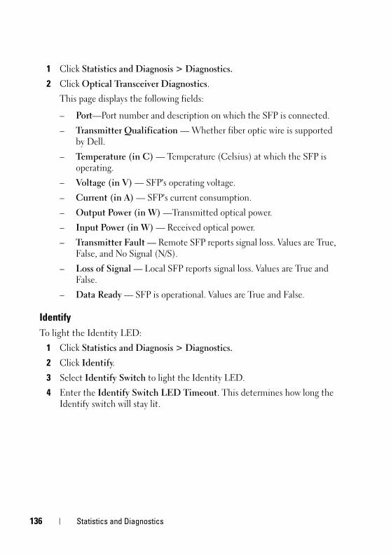
1
FILE LOCATION: C:\Users\vijaya_devakumar_dev\Documents\PowerConnect\Astute\Docs for Web
D E L L C O N F I D E N T I A L – P R E L I M I N A R Y 3 / 1 9 / 1 5 - F O R P R O O F O N LY
1 Click Statistics and Diagnosis > Diagnostics.
2 Click Optical Transceiver Diagnostics.
This page displays the following fields:
– Port—Port number and description on which the SFP is connected.
– Transmitter Qualification — Whether fiber optic wire is supported by Dell.
– Temperature (in C) — Temperature (Celsius) at which the SFP is operating.
– Voltage (in V) — SFP's operating voltage.
– Current (in A) — SFP's current consumption.
– Output Power (in W) —Transmitted optical power.
– Input Power (in W) — Received optical power.
– Transmitter Fault — Remote SFP reports signal loss. Values are True, False, and No Signal (N/S).
– Loss of Signal — Local SFP reports signal loss. Values are True and False.
– Data Ready — SFP is operational. Values are True and False.
IdentifyTo light the Identity LED:
1 Click Statistics and Diagnosis > Diagnostics.
2 Click Identify.
3 Select Identify Switch to light the Identity LED.
4 Enter the Identify Switch LED Timeout. This determines how long the Identify switch will stay lit.
36 Statistics and Diagnostics

FILE LOCATION: C:\Users\vijaya_devakumar_dev\Documents\PowerConnect\Astute\Docs for Web
D E L L C O N F I D E N T I A L – P R E L I M I N A RY 3 / 1 9 / 1 5 - F O R P R O O F O N LY
9Network Administration: VLANThis chapter describes how VLANs are configured on the device.
It contains the following topics:
• VLAN Overview
• Standard VLAN
• Voice VLAN
VLAN OverviewA switched network can be logically segmented into multiple VLANs on an organizational basis, by functions, project teams, or applications rather than on a physical or geographical basis. For example, all workstations and servers used by a particular workgroup team can be connected to the same VLAN, regardless of their physical connections to the network, or the fact that they might be intermingled with other teams. Reconfiguration of the network can be done through software rather than by physically unplugging and moving devices or wires.
A VLAN can be thought of as a Broadcast domain that exists within a defined set of switches. A VLAN consists of a number of end systems, either hosts or network equipment (such as bridges and routers), connected by a single bridging domain. VLANs are supported by VLAN switches that provide bridging of packets between devices that belong to the same VLAN.
VLANs are created to provide the segmentation services traditionally provided by routers in LAN configurations. VLANs address scalability, security, and network management. Routers in VLAN topologies provide broadcast filtering, security, address summarization, and traffic flow management.
None of the switches, within a defined group, will bridge any frames, not even Broadcast frames, between two VLANs.
Network Administration: VLAN 137

1
FILE LOCATION: C:\Users\vijaya_devakumar_dev\Documents\PowerConnect\Astute\Docs for Web
D E L L C O N F I D E N T I A L – P R E L I M I N A R Y 3 / 1 9 / 1 5 - F O R P R O O F O N LY
Frame FlowFigure 9-1 describes the flow of VLAN frames from the Ingress port to the Egress port:
Figure 9-1. Frame Flow Through a VLAN
When a frame is received, it must be assigned a VLAN. VLAN assignment is accomplished by the following steps:
1 If the frame contains a VLAN tag, that tag is used, otherwise the frame is classified by the port's default VLAN (PVID), if it is defined.
2 After classification, the frame may pass (if enabled) through ingress filtering, where the frame is dropped if the frame's VLAN ID is not one of the VLANs to which the ingress port belongs.
3 A forwarding decision is made, as a function of the VLAN ID and the destination MAC address.
4 The egress rules define whether the frame is to be sent as tagged or untagged.
Special-case VLANsVLAN#1 and VLAN#4095 are special-case VLANs:
• VLAN — Defined as the default VLAN. This means that if the VLAN, whose VID is the current port's PVID, is deleted from the port (or from the system), that port's PVID is set to 1. VLAN#1 cannot be deleted from the system.
• VLAN4095 — Defined (according to standard and industry practice) as the discard VLAN. A frame classified to this VLAN is silently dropped.
Ingress Egress
VLANClassification
IngressFiltering
EgressFiltering
Progress
ForwardingDecision
FilteringDatabase
ReceivedFrame
TransmittedFrame
Ingress Egress
VLANClassification
IngressFiltering
VLANClassification
IngressFiltering
EgressFiltering
Progress
ForwardingDecision
FilteringDatabase
ReceivedFrame
TransmittedFrame
38 Network Administration: VLAN

FILE LOCATION: C:\Users\vijaya_devakumar_dev\Documents\PowerConnect\Astute\Docs for Web
D E L L C O N F I D E N T I A L – P R E L I M I N A RY 3 / 1 9 / 1 5 - F O R P R O O F O N LY
QinQ TaggingQinQ enables packets between sites of a customer network to be forwarded over a provider network. The device is a provider bridge that supports c-tagged service interface to which the customer network/site connects.
QinQ tagging adds a service VLAN tag to customer-tagged packets when forwarding customer packets into the provider network. The added tag provides a VLAN ID to each customer, which ensures private and segregated network traffic. The VLAN ID tag is assigned to a customer port in the service provider network. This enables administrators to expand service to VLAN users.
The supported ethernet type is 0x8100.
Port ModesPorts participating in Layer 2 switching may be classified as:
• Access Ports
Ports set to Access mode belong to a single VLAN, whose VID is the currently set PVID (default =1). These ports accept all untagged frames, and all frames tagged with the VID, currently set as the port's PVID. All traffic egress to access ports is sent untagged. If the VLAN, whose VID is set as the current PVID of the port, is deleted from the system, or deleted from the port, the port's PVID will be set to 1, meaning that the port will be made a member of VLAN1, the default VLAN.
Ingress filtering is always enabled for ports in Access mode.
Setting an Access port’s PVID to 4095 effectively shuts it down, as no frames will be transferred in either direction.
Access mode ports are intended to connect end-stations to the system, especially when the end-stations are incapable of generating VLAN tags.
• Trunk Ports
Ports set to Trunk mode can belong to multiple VLANs. The default VLAN membership of a trunk port is all VLANs (1-4094). A PVID must be set on the port (it can be a non-existing VLAN). Trunk ports accept tagged and untagged frames. Untagged frames will be classified to the VLAN whose VLAN ID (VID) is configured as the port’s PVID.
Network Administration: VLAN 139

1
FILE LOCATION: C:\Users\vijaya_devakumar_dev\Documents\PowerConnect\Astute\Docs for Web
D E L L C O N F I D E N T I A L – P R E L I M I N A R Y 3 / 1 9 / 1 5 - F O R P R O O F O N LY
Frames, whose VID is the PVID of the egress port, are sent untagged. Frames sent in all other VLANs active on the port are sent tagged.
Ingress filtering is always enabled on Trunk-mode ports. Incoming frames will undergo ingress filtering, and if correctly tagged, (tagged with a VID of one of the VLANs to which the port currently belongs) are admitted.
The default PVID is 1 (the default VLAN). If another VID is configured as the port’s PVID, and the corresponding VLAN is deleted from the port or from the system, the port’s PVID reverts to 1, meaning that the port is made a member of the default VLAN.
Setting a trunk-port’s PVID to 4095 limits traffic to tagged frames. Incoming untagged frames are silently discarded, and no frames are sent untagged.
Trunk-mode ports are intended for switch-to-switch links, where traffic is usually tagged.
• General Ports
Ports set to General mode can be members of multiple VLANs. Each of these VLANs may be configured to be tagged or untagged. This setting applies to transmitted frames. Incoming untagged frames are classified into the VLAN whose VID is the currently configured PVID.
Ingress filtering may be disabled on General ports. Ingress filtering is enabled by default.
• Promiscuous Ports
A promiscuous port can communicate with all ports of the same Private VLAN (PVLAN), including the isolated ports of the same PVLAN.
• Isolated
An isolated port has complete Layer 2 isolation from the other ports within the same PVLAN, but not from the promiscuous ports. Isolated ports can communicate with promiscuous ports.
In the factory default configuration, all ports are designated as Access ports, and are associated with the default VLAN.
40 Network Administration: VLAN

FILE LOCATION: C:\Users\vijaya_devakumar_dev\Documents\PowerConnect\Astute\Docs for Web
D E L L C O N F I D E N T I A L – P R E L I M I N A RY 3 / 1 9 / 1 5 - F O R P R O O F O N LY
Acceptable Frame TypeThe acceptable frame type can be set on a port to accept all frames (tagged and untagged), tagged only, or untagged only. This setting takes precedence over all other settings, so that if the acceptable frame type is tagged only, incoming untagged frames are silently discarded, even if the port has a valid PVID.
Standard VLANThis section describes standard (non-voice) VLANs. It covers the following topics:
• VLAN Membership
• VLAN Port Settings
• Protocol Group
• Protocol Port
• GVRP Parameters
• GARP Timers
• Private VLAN
VLAN Membership
The device supports up to 4094 VLANs (VLANs 1-4094).
Ports are assigned to a VLAN in the VLAN Port Settings page.
To configure the ports in a VLAN:
1 Click Network Administration > VLAN >Standard VLAN > VLAN Membership.
Each existing port/LAG is labeled with one of the following codes, regarding its membership in the VLAN:
– T — Tagged. The interface is a member of a VLAN. All packets egress to the interface are tagged. The packets contain VLAN information.
– S — Static. The VLAN is user-defined.
– U — Untagged. The interface is a member of a VLAN. Packets egress to the interface are untagged.
– F — Forbidden. The interface is denied membership to a VLAN.
Network Administration: VLAN 141

1
FILE LOCATION: C:\Users\vijaya_devakumar_dev\Documents\PowerConnect\Astute\Docs for Web
D E L L C O N F I D E N T I A L – P R E L I M I N A R Y 3 / 1 9 / 1 5 - F O R P R O O F O N LY
– None — The interface is not a VLAN member. Packets associated with the interface are not forwarded.
2 Click Edit and enter the fields:
– VLAN — Select a VLAN ID to configure.
– VLAN Name — Displays the VLAN name.
– Status — Displays the VLAN type. Possible values are:
• Dynamic — The VLAN was dynamically created through GVRP.
• Static — The VLAN is user-defined.
– Authentication Not Required — Enable/disable authentication on the VLAN. 802.X unauthenticated VLANs are used when connecting equipment that does not support 802.X, such as an IP phone. If 802.1X is not in use, or if 802.1X authentication is required, select Disabled.
VLAN Port SettingsAfter a VLAN has been defined, ports can be assigned to it.
To assign a VLAN to untagged packets, arriving on the device, set the port default VLAN ID (PVID) to the port. All untagged packets arriving to the device are tagged by the ports PVID.
All ports must have a defined PVID. If no other value is configured, the default VLAN PVID is used. VLAN ID #1 is the default VLAN, and cannot be deleted from the system.
NOTE: In Access mode, a port can only be a member in a single VLAN, so before adding an access port to the VLAN, the VLAN the port is currently a member in should be manually removed (by selecting it from the VLAN list and clicking the remove button).
To configure ports on a VLAN:
1 Click Network Administration > VLAN >Standard VLAN > VLAN Port Settings.
All interfaces and their settings are displayed.
2 Click Edit.
3 Select a port, click its Edit icon and enter the fields:
– Port — Displays the port number to be modified.
42 Network Administration: VLAN

FILE LOCATION: C:\Users\vijaya_devakumar_dev\Documents\PowerConnect\Astute\Docs for Web
D E L L C O N F I D E N T I A L – P R E L I M I N A RY 3 / 1 9 / 1 5 - F O R P R O O F O N LY
– Switchport Mode — Enter the port system mode. The possible options are:
• Layer 2 — Set the port to layer 2 mode.
• Layer 3 — Set the port to layer 3 mode in which static routing is supported. For Layer 3 ports, the fields below are not relevant.
– Port VLAN Mode — Enter the port VLAN mode. The possible options are:
• General — The port belongs to VLANs, and each VLAN is user-defined as tagged or untagged (full 802.1Q mode).
• Access — The port belongs to a single untagged VLAN. When a port is in Access mode, the frame types that are accepted on the port cannot be designated. Ingress filtering cannot be enabled/disabled on an access port.
• Trunk — The port belongs to VLANs on which all ports are tagged (except for one port that can be untagged).
• Customer — When a port is in Customer mode, an added tag provides a VLAN ID to each customer, ensuring private and segregated network traffic for that customer.
• Private VLAN Promiscuous — The port is a promiscuous port.
• Private VLAN Host — The port is an isolated port
– Current Reserved VLAN — Displays the VLAN currently designated by the system as the VLAN reserved for internal use.
– Reserve VLAN for Internal Use (1-4094) — Check to enter a reserved VLAN, and enter its ID. If none is required, check None.
– PVID — Enter a VLAN ID to be added to untagged packets. The possible values are 1-4095. VLAN 4095 is defined according to standard and industry practice as the discard VLAN. Packets classified to the discard VLAN are dropped.
– VLAN List — Enter the VLAN(s) to which this LAG belongs.
Click Add/Remove to move the LAG to the VLAN list together with its type.
Network Administration: VLAN 143
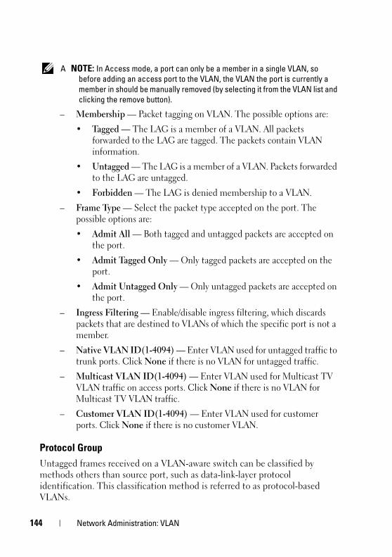
1
FILE LOCATION: C:\Users\vijaya_devakumar_dev\Documents\PowerConnect\Astute\Docs for Web
D E L L C O N F I D E N T I A L – P R E L I M I N A R Y 3 / 1 9 / 1 5 - F O R P R O O F O N LY
A NOTE: In Access mode, a port can only be a member in a single VLAN, so before adding an access port to the VLAN, the VLAN the port is currently a member in should be manually removed (by selecting it from the VLAN list and clicking the remove button).
– Membership — Packet tagging on VLAN. The possible options are:
• Tagged — The LAG is a member of a VLAN. All packets forwarded to the LAG are tagged. The packets contain VLAN information.
• Untagged — The LAG is a member of a VLAN. Packets forwarded to the LAG are untagged.
• Forbidden — The LAG is denied membership to a VLAN.
– Frame Type — Select the packet type accepted on the port. The possible options are:
• Admit All — Both tagged and untagged packets are accepted on the port.
• Admit Tagged Only — Only tagged packets are accepted on the port.
• Admit Untagged Only — Only untagged packets are accepted on the port.
– Ingress Filtering — Enable/disable ingress filtering, which discards packets that are destined to VLANs of which the specific port is not a member.
– Native VLAN ID(1-4094) — Enter VLAN used for untagged traffic to trunk ports. Click None if there is no VLAN for untagged traffic.
– Multicast VLAN ID(1-4094) — Enter VLAN used for Multicast TV VLAN traffic on access ports. Click None if there is no VLAN for Multicast TV VLAN traffic.
– Customer VLAN ID(1-4094) — Enter VLAN used for customer ports. Click None if there is no customer VLAN.
Protocol Group Untagged frames received on a VLAN-aware switch can be classified by methods others than source port, such as data-link-layer protocol identification. This classification method is referred to as protocol-based VLANs.
44 Network Administration: VLAN

FILE LOCATION: C:\Users\vijaya_devakumar_dev\Documents\PowerConnect\Astute\Docs for Web
D E L L C O N F I D E N T I A L – P R E L I M I N A RY 3 / 1 9 / 1 5 - F O R P R O O F O N LY
Protocol-based VLANs are useful for isolating Layer 2 traffic of various Layer 3 protocols. If, for example, a switch serves IP stations and IPX stations that communicate with a single VLAN-unaware server, without using protocol-based VLANs, all the Layer 2 Broadcast traffic would reach all the stations. With protocol-based VLANs, the switch can forward incoming traffic of a specific protocol from the server to stations to the VLAN for this protocol only.
Protocol-based VLANs are only available on General ports.
Classification rules are set on a per-port basis, and may be sensitive to the frame's encapsulation. The default encapsulation assumed is Ethernet.
On each port, a user can define associations between groups of data-link layer protocols and ports. For each group/port combination, the user may set the VLAN to which incoming frames on that port will be classified if they belong to any of the protocols in the group.
Several protocol-groups may be associated to a single port, and a protocol group may be assigned to multiple ports, if so desired.
It is not guaranteed that the VLAN to which the frame is classified exists in the system, or is active on that port.
The following frames (packet) types are supported: Ethernet, RFC 1042, and LLC Other.
There may be dependencies between protocols and encapsulations, and specifying one protocol may automatically add additional protocols to the protocol-group, such as specifying IP implies ARP and vice-versa.
Similarly, there may be implied dependencies between encapsulations, so that specifying an encapsulation implies defining the protocol group for related encapsulations. An example of this is specifying the Ethernet encapsulation, even by default, implies IEEE802 encapsulation, as per RFC 1042.
The following standards are relevant:
• IEEE802.1V defines VLAN assignment by protocol type.
• IETF RFC 10-2 defines a standard for the transmission of IP datagrams over IEEE 802 Networks
Network Administration: VLAN 145

1
FILE LOCATION: C:\Users\vijaya_devakumar_dev\Documents\PowerConnect\Astute\Docs for Web
D E L L C O N F I D E N T I A L – P R E L I M I N A R Y 3 / 1 9 / 1 5 - F O R P R O O F O N LY
Defining Protocol Groups
Define a protocol group by performing the following steps:
1 Define a protocol group by assigning one or more protocols to the group and giving it a protocol-group ID (any integer), using the Protocol Group page.
2 Associate the group with a desired VLAN classification, per port, using the Protocol Port page.
To define a protocol group:
1 Click Network Administration > VLAN > Standard VLAN >Protocol Group.
The currently-defined protocol groups are displayed.
2 Click Edit, Add and enter the fields:
– Frame Type — Select a frame type to be accepted in the protocol group.
– Protocol Value — Select a protocol name.
or
– Ethernet-Based Protocol Value (0600 - FFFF) — Enter the Ethernet protocol group type.
– Protocol Group ID — Assign a protocol group ID number.
Protocol Port A protocol port is a port assigned to a particular protocol group. Traffic from particular types of frames can be assigned to a protocol group, which has a port and VLAN associated with it. The VLAN must be created before the protocol group can be created.
To add an interface to a protocol group:
1 Click Network Administration > VLAN > Standard VLAN > Protocol Port.
A list of previously-defined protocol groups is displayed.
2 Click Edit, Add, and enter the fields:
– Interface Type — Select either Port or LAG.
– Interface — Select the interface to be added to a protocol group.
46 Network Administration: VLAN

FILE LOCATION: C:\Users\vijaya_devakumar_dev\Documents\PowerConnect\Astute\Docs for Web
D E L L C O N F I D E N T I A L – P R E L I M I N A RY 3 / 1 9 / 1 5 - F O R P R O O F O N LY
– Group ID — Select a protocol group ID to which the interface is added.
Protocol ports can either be attached to a VLAN identified either by ID or VLAN name.
– VLAN ID—Check and enter a VLAN ID.
or
– VLAN Name — Check and enter a VLAN name.
GVRP Parameters GARP VLAN Registration Protocol (GVRP) is used for automatic distribution of VLAN membership information among VLAN-aware bridges. GVRP enables VLAN-aware bridges to automatically learn VLANs-to-bridge-ports mapping, without having to individually configure each bridge and register VLAN membership.
To ensure the correct operation of the GVRP protocol, it is advised to set the maximum number of GVRP VLANs equal to a value which significantly exceeds:
– The number of all static VLANs both currently configured and expected to be configured.
– The number of all dynamic VLANs participating in GVRP, both currently configured (initial number of dynamic GVRP VLANs is 128) and expected to be configured.
To set GVRP parameters:
1 Click Network Administration > VLAN > Standard VLAN > GVRP Parameters.
2 Click Edit.
3 Select either Ports or LAGs to view that type of interface in the page.
4 Select a port, click its Edit icon and enter the fields:
– GVRP State — Enable/disable GVRP on the interface.
– Dynamic VLAN Creation — Enable/disable Dynamic VLAN creation on the interface.
– GVRP Registration — Enable/disable VLAN registration through GVRP on the interface.
Network Administration: VLAN 147

1
FILE LOCATION: C:\Users\vijaya_devakumar_dev\Documents\PowerConnect\Astute\Docs for Web
D E L L C O N F I D E N T I A L – P R E L I M I N A R Y 3 / 1 9 / 1 5 - F O R P R O O F O N LY
GARP TimersGeneric Attribute Registration Protocol (GARP) is a general-purpose protocol that registers network connectivity or membership-style information. GARP defines a set of devices interested in a given network attribute, such as VLAN information or the Multicast address.
GARP provides a generic framework whereby devices in a bridged LAN, such as end stations and switches, can register and de-register attribute values, such as VLAN identifiers, with each other. In doing so, these attributes are propagated to devices in the bridged LAN, and these devices form a reachability tree that is a subset of an active topology. GARP defines the architecture, rules of operation, state machines and variables for the registration and deregistration of attribute values.
When configuring GARP, ensure the following:
• The leave time must be greater than or equal to three times the join time.
• The leave-all time must be greater than the leave time.
• Set the same GARP timer values on all Layer 2-connected devices. If the GARP timers are set differently on the Layer 2-connected devices, GARP application does not operate successfully.
To enable a GARP timer on an interface:
1 Click Network Administration > VLAN > Standard VLAN > GARP Timers.
The GARP timers are displayed.
2 Select either Ports or LAGs to view that type of interface in the page.
3 Click Edit.
4 Select a port, click its Edit icon and enter the fields:
– GARP Join Timer (mSec) — Enter the time during which Protocol Data Units (PDU) are transmitted.
– GARP Leave Timer (mSec) — Enter the time interval during which the device waits before leaving its GARP state. Leave time is activated by a Leave All Time message sent/received, and cancelled by the Join message received. Leave time must be greater than or equal to three times the join time.
48 Network Administration: VLAN

FILE LOCATION: C:\Users\vijaya_devakumar_dev\Documents\PowerConnect\Astute\Docs for Web
D E L L C O N F I D E N T I A L – P R E L I M I N A RY 3 / 1 9 / 1 5 - F O R P R O O F O N LY
– GARP Leave All Timer (mSec) — Enter time interval which all devices wait before leaving the GARP state. The leave all time must be greater than the leave time.
Private VLAN Private VLANs (PVLANs) provide Layer 2 isolation between ports that share the same Broadcast domain, or in other words, they create a point-to-multipoint Broadcast domain. The ports can be located anywhere in the Layer 2 network.
The switch ports belonging to a PVLAN, can be:
• Promiscuous ports that can communicate with all ports of the same PVLAN, including the isolated ports of the same PVLAN.
• Isolated ports that have complete Layer 2-isolation from the other ports within the same PVLAN, but not from the promiscuous ports. Isolated ports can communicate with promiscuous ports.
The PVLAN entity is implemented by allocating the following VLANs per PVLAN:
• Primary VLAN — Carries traffic from promiscuous ports.
• Isolated VLAN — Carries traffic from isolated ports.
To configure PVLANs:
1 Click Network Administration > VLAN > Standard VLAN > Private VLAN.
The previously-defined private VLANs are displayed.
2 To query by Associated Primary VLAN ID, enter a VLAN ID, and click Query. The associated VLANs are displayed.
3 To define a private VLAN, click Edit, Assign and enter the fields:
– Private VLAN ID — Select a VLAN to be assigned.
– Private VLAN Type — Select one of the possible options:
• Primary — Traffic from promiscuous ports flow through this type of VLAN. This is for the Internet or shared servers.
• Isolated —Traffic from isolated ports flow through this type of VLAN.
Network Administration: VLAN 149

1
FILE LOCATION: C:\Users\vijaya_devakumar_dev\Documents\PowerConnect\Astute\Docs for Web
D E L L C O N F I D E N T I A L – P R E L I M I N A R Y 3 / 1 9 / 1 5 - F O R P R O O F O N LY
– Associate Primary VLAN — If the Private VLAN type is Isolated, check to associate the isolated VLAN with a primary VLAN, thus allowing traffic between isolated and promiscuous ports.
– Primary VLAN ID — Select a VLAN to be associated with the isolated VLAN.
4 To assign ports to the private VLAN, click Edit, Membership.
5 Select a Primary VLAN ID.
6 Select the ports to be assigned to each VLAN, and assign each port/LAG a port type. The possible options are:
– H - Host (Isolated) — Port is isolated.
– P - Promiscuous — Port is promiscuous.
– C - Conditional (operational state depends on Port VLAN Mode) — Port receives the Port VLAN type set in VLAN Port Settings.
– None — Clears port type previously selected.
See "Port Modes" on page 139 for a description of the various port modes.
Voice VLAN This section describes voice VLAN. It covers the following topics:
• Overview
• Properties
• Port Settings
• OUI
OverviewThe Voice VLAN feature enables configuring ports to carry IP-voice traffic from IP phones on a specific voice VLAN that is dedicated to voice traffic. This VLAN is configured with a QoS profile that ensures high voice quality.
VoIP phones transmits IP traffic with a pre-configured Organizational Unique Identifier (OUI) prefix in the source MAC address. This enables the switch to dynamically identify ports connected to VoIP equipment and automatically add these ports to the Voice VLAN.
50 Network Administration: VLAN

FILE LOCATION: C:\Users\vijaya_devakumar_dev\Documents\PowerConnect\Astute\Docs for Web
D E L L C O N F I D E N T I A L – P R E L I M I N A RY 3 / 1 9 / 1 5 - F O R P R O O F O N LY
VoIP phones use one of the following modes, both of which are supported by the device:
• Use only tagged packets for all communications.
• Initially use untagged packets while retrieving the initial IP address through DHCP. Then use the Voice VLAN and start sending tagged VoIP packets.
Non-VoIP traffic is dropped from the Voice VLAN when the device is in Auto Voice VLAN secured mode.
The Voice VLAN feature provides QoS actions to VoIP, ensuring that the quality of voice does not deteriorate if IP traffic is received unevenly.
To summarize, when Voice VLAN is enabled and configured, and VoIP equipment is connected to one of the switch ports, the VoIP traffic triggers the switch’s Voice VLAN feature to add this port to the Voice VLAN, and to assign traffic from this port a specific QoS profile, ensuring high voice quality.
The device supports a single voice VLAN.
PropertiesTo set voice VLAN parameters that apply to the voice VLAN on the device:
1 Click Network Administration > VLAN > Voice VLAN > Properties.
2 Click Edit and enter the fields:
– Voice VLAN State — Select Enable/Disable to active/deactivate the Voice VLAN feature on the device.
– Voice VLAN ID — Select the VLAN that is to be the voice VLAN.
– Class of Service — Select to add a CoS level to untagged packets, received on the voice VLAN. The possible values are 0 to 7, where 7 is the highest priority. 0 is used as a best-effort, and is invoked automatically when no other value has been set.
– Remark CoS — Select Enable to use the Remark CoS feature.
– Voice VLAN Aging Time — Enter the interval of time after which the port exits the voice VLAN, if no voice packets are received.
The aging time starts after the MAC address is aged out of the Dynamic MAC Address table. The default time is 300 sec. For more information on defining MAC address age out time, see "Dynamic Address Table" on page 168.
Network Administration: VLAN 151
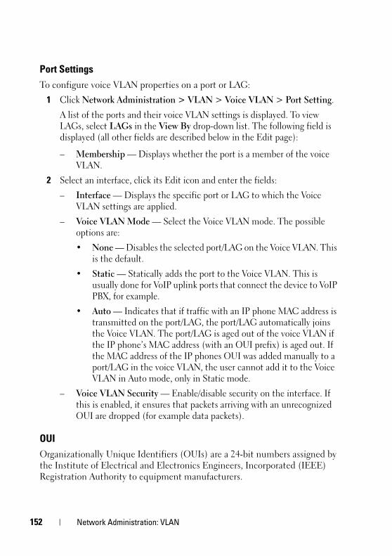
1
FILE LOCATION: C:\Users\vijaya_devakumar_dev\Documents\PowerConnect\Astute\Docs for Web
D E L L C O N F I D E N T I A L – P R E L I M I N A R Y 3 / 1 9 / 1 5 - F O R P R O O F O N LY
Port SettingsTo configure voice VLAN properties on a port or LAG:
1 Click Network Administration > VLAN > Voice VLAN > Port Setting.
A list of the ports and their voice VLAN settings is displayed. To view LAGs, select LAGs in the View By drop-down list. The following field is displayed (all other fields are described below in the Edit page):
– Membership — Displays whether the port is a member of the voice VLAN.
2 Select an interface, click its Edit icon and enter the fields:
– Interface — Displays the specific port or LAG to which the Voice VLAN settings are applied.
– Voice VLAN Mode — Select the Voice VLAN mode. The possible options are:
• None — Disables the selected port/LAG on the Voice VLAN. This is the default.
• Static — Statically adds the port to the Voice VLAN. This is usually done for VoIP uplink ports that connect the device to VoIP PBX, for example.
• Auto — Indicates that if traffic with an IP phone MAC address is transmitted on the port/LAG, the port/LAG automatically joins the Voice VLAN. The port/LAG is aged out of the voice VLAN if the IP phone’s MAC address (with an OUI prefix) is aged out. If the MAC address of the IP phones OUI was added manually to a port/LAG in the voice VLAN, the user cannot add it to the Voice VLAN in Auto mode, only in Static mode.
– Voice VLAN Security — Enable/disable security on the interface. If this is enabled, it ensures that packets arriving with an unrecognized OUI are dropped (for example data packets).
OUIOrganizationally Unique Identifiers (OUIs) are a 24-bit numbers assigned by the Institute of Electrical and Electronics Engineers, Incorporated (IEEE) Registration Authority to equipment manufacturers.
52 Network Administration: VLAN

FILE LOCATION: C:\Users\vijaya_devakumar_dev\Documents\PowerConnect\Astute\Docs for Web
D E L L C O N F I D E N T I A L – P R E L I M I N A RY 3 / 1 9 / 1 5 - F O R P R O O F O N LY
Up to 16 OUIs can be stored on the switch. Nine specific OUIs of popular VoIP phones manufacturers are stored by default, as shown in the following table:.
Traffic from each type of IP phone contains the OUI for the phone manufacturer. When frames are received, in which the source MAC address’s first three octets match one of the OUIs in the OUI list, the port on which they are received is automatically assigned to the Voice VLAN.
To add a new OUI:
1 Click Network Administration > VLAN > Voice VLAN > OUI.
The previously-defined OUIs are displayed.
2 Click Edit, Add, and enter the fields:
– Telephony OUI — Enter a new OUI.
– Description — Enter an OUI description up to 32 characters.
Default OUIs
00:01:81 Nortel
00:01:e3 Siemens_AG_phone
00:03:6b Cisco_phone
00:09:6e Avaya
00:0f:e2 H3C_Aolynk
00:10:49 Shoretel
00:60:b9 Philips_and_NEC_AG_phone
00:90:7a Polycom/Veritel_phone
00:e0:bb 3Com_phone
Network Administration: VLAN 153

1
FILE LOCATION: C:\Users\vijaya_devakumar_dev\Documents\PowerConnect\Astute\Docs for Web
D E L L C O N F I D E N T I A L – P R E L I M I N A R Y 3 / 1 9 / 1 5 - F O R P R O O F O N LY
54 Network Administration: VLAN

FILE LOCATION: C:\Users\vijaya_devakumar_dev\Documents\PowerConnect\Astute\Docs for Web
D E L L C O N F I D E N T I A L – P R E L I M I N A RY 3 / 1 9 / 1 5 - F O R P R O O F O N LY
10Network Administration: Port SettingsThis section describes how to configure port functionality.
It contains the following topics:
• Ports
• Address Tables
• UDLD
PortsThis section covers the following topics:
• Jumbo Frames
• Protected Ports
• Port Profile
• Port Configuration
• Port and VLAN Mirrorings
OverviewThis section includes a description of port features and describes the following:
• Auto-Negotiation
• MDI/MDIX
• Flow Control
• Back Pressure
• Port Default Settings
Network Administration: Port Settings 155

1
FILE LOCATION: C:\Users\vijaya_devakumar_dev\Documents\PowerConnect\Astute\Docs for Web
D E L L C O N F I D E N T I A L – P R E L I M I N A R Y 3 / 1 9 / 1 5 - F O R P R O O F O N LY
The device supports 802.3x flow control for ports configured to Full Duplex mode. By default, this feature is enabled on all ports, and it can be disabled per port.
The device supports back pressure for BaseT copper ports configured to Half Duplex mode. By default, this feature is disabled, and it can be enabled per port. The back-pressure mechanism prevents the sender from transmitting additional traffic temporarily. The receiver may occupy a link so it becomes unavailable for additional traffic.
Port default settings are described in Table 10-1.
Auto-Negotiation
Auto-negotiation enables automatic detection of speed, duplex mode and flow control on all switching 10/100/1000BaseT ports. Auto-negotiation is enabled on all ports by default.
Auto-negotiation is a mechanism established between two link partners to enable a port to advertise its transmission rate, duplex mode and flow control abilities to its partner. Both ports then operate at the highest common denominator.
If connecting a Network Interface Card (NIC) that does not support auto-negotiation or is not set to auto-negotiation, both the device switching port and the NIC must be manually set to the same speed and duplex mode.
If the station, on the other side of the link, attempts to auto-negotiate with a device 100BaseT port that is configured to full duplex, the auto-negotiation results in the station attempting to operate in half duplex.
MDI/MDIX
The device supports auto-detection of straight-through and crossed cables on all 10/100/1000BaseT ports. This feature is part of auto-negotiation and is enabled when Auto-negotiation is enabled.
When the MDI/MDIX (Media Dependent Interface with Crossover) is enabled, the automatic correction of errors in cable selection is possible, thus making the distinction between a straight-through cable and a crossover cable irrelevant. The standard wiring for end stations is known as MDI (Media Dependent Interface), and the standard wiring for hubs and switches is known as MDIX.
56 Network Administration: Port Settings

FILE LOCATION: C:\Users\vijaya_devakumar_dev\Documents\PowerConnect\Astute\Docs for Web
D E L L C O N F I D E N T I A L – P R E L I M I N A RY 3 / 1 9 / 1 5 - F O R P R O O F O N LY
Flow Control
The device supports 802.3x flow control for ports configured to Full Duplex mode. By default, this feature is enabled on all ports, and it can be disabled per port.
Flow control creates a lossless link with no packet loss. The flow control mechanism enables the receiving side to signal to the transmitting side that transmission must temporarily be halted to prevent buffer overflow. This signaling is done by sending PAUSE frames. The ports that receive pause frames stops transmitting traffic.
Flow control on the device works in Receive-Only mode, meaning that the interfaces with enabled flow control receive PAUSE frames, but do not send them.
When flow control is enabled, the system buffers are allocated per port so that if the buffers of one port are consumed, other ports will still have their free buffers.
Back Pressure
The device supports back pressure for BaseT copper ports configured to Half Duplex mode. By default, this feature is disabled, and it can be enabled per port. The back-pressure mechanism prevents the sender from transmitting additional traffic temporarily. The receiver may occupy a link so it becomes unavailable for additional traffic.
Back Pressure is supported on all SKUs except for X4012.
Port Default Settings
Table 10-1 describes the port default settings.Table 10-1. Port Default Settings
Function Default Setting
Port speed and mode 1G ports default speed: 1G
10G port default speed: 10G
Port forwarding state Enabled
Port tagging All ports are members of VLAN 1 as untagged
Flow Control Enabled
Back Pressure Disabled
Network Administration: Port Settings 157

1
FILE LOCATION: C:\Users\vijaya_devakumar_dev\Documents\PowerConnect\Astute\Docs for Web
D E L L C O N F I D E N T I A L – P R E L I M I N A R Y 3 / 1 9 / 1 5 - F O R P R O O F O N LY
Jumbo FramesJumbo frames are frames of up to 10 Kb in size. If jumbo frames are not enabled, the system supports a packet size of up to 2K bytes.
To enable jumbo frames:
1 Click Network Administration > Ports Settings > Jumbo Frames.
The current jumbo frames setting is displayed.
2 To enable/disable jumbo frames, click Edit.
NOTE: You must save the configuration and reboot the device in order to make jumbo frames operational.
Protected Ports Protected ports provide Layer 2 isolation between interfaces (Ethernet ports and LAGs) that share the same Broadcast domain (VLAN) with other interfaces. This can be used to set up a group of ports that receive similar services.
Protected ports provides Layer 2 isolation within the device, while Private VLAN can be used to create Layer 2 isolation that is carried on VLANs, thus it can be used over multiple devices.
A protected port does not forward traffic (Unicast, Multicast, or Broadcast) to any other protected port on the same switch.
A community is a group of protected ports. Protected ports within the same community can forward traffic to each other.
The following types of ports can be defined:
• Protected Port — Can send traffic only to uplink ports.
• Community Port — A protected port that is associated with a community. It can send traffic to other protected ports in the same community and to uplink ports.
• Uplink Port — An uplink port is an unprotected port that can send traffic to any port.
• Isolated Port — A protected port that does not belong to a community. Isolated ports can send traffic only to uplink ports.
58 Network Administration: Port Settings

FILE LOCATION: C:\Users\vijaya_devakumar_dev\Documents\PowerConnect\Astute\Docs for Web
D E L L C O N F I D E N T I A L – P R E L I M I N A RY 3 / 1 9 / 1 5 - F O R P R O O F O N LY
Port Protection is independent of all other features and configuration settings. Two protected ports in a common VLAN cannot communicate with each other.
Protected Port Restrictions
The following restrictions apply to protected ports:
• When a protected port is placed in a LAG, it loses its protected port attribute and takes upon itself the LAG's protection attributes. When the port is removed from the LAG, its attributes are re-applied.
• Mirrored traffic is not subject to protected ports rules.
• Routing is not affected by the protected port forwarding rule, so that if a packet enters a protected port, it can be routed by the device to another protected port.
Configuration of Protected Ports
To configure protected ports and establish their communities:
1 Click Network Administration > Ports Settings > Protected Ports.
A summary of all the ports and their statuses is displayed.
2 Click Edit.
3 Select the interface and click its Edit icon.
4 Enter values for the following fields:
• State — Select Protected/Unprotected to enable/disable port protection.
• Community — Select the number of the community (1-30) to which to add the port, or define the port as Isolated.
Port Profile
Port profiles provide a convenient way to configure a port or group of ports, such that they are suitable to be connected to a desktop device (PC), IP phone, switch, router or wireless configuration access point.
Port profiles can be applied to a specific interface, a range of interfaces, or globally.
Network Administration: Port Settings 159

1
FILE LOCATION: C:\Users\vijaya_devakumar_dev\Documents\PowerConnect\Astute\Docs for Web
D E L L C O N F I D E N T I A L – P R E L I M I N A R Y 3 / 1 9 / 1 5 - F O R P R O O F O N LY
To assign a profile to a port:
1 Click Network Administration > Ports Settings > Port Profile.
A summary of all the interfaces and their profiles is displayed.
2 To assign a profile to an interface, click Edit.
3 Select an interface and click its Edit icon.
4 Select an Assigned Profile to assign to the interface. The Profile Description is displayed. The following options are available:
– Desktop—The port will be connected to a PC.
– Phone—The port will be connected to a IP phone.
– Switch—The port will be connected to a switch.
– Router—The port will be connected to a router.
– Wireless—The port will be connected to a wireless access point.
5 Each profile requires entering various elements of VLAN information. Enter the fields according to the profile:
– VLAN Port Mode — Displays the port mode applied to ports in the profile.
– VLAN ID - Untagged (1-4094) — Enter the VLAN for untagged traffic.
– VLAN ID - Tagged (1-4094) — Enter the VLAN for tagged traffic.
– Native VLAN ID(1-4094) — Enter the VLAN ID used for untagged traffic to trunk ports, or check None.
The remaining fields on this page are display-only, and describe the port configuration of the profile. The following fields are described:
Port Security fields:
– Mode — Learning mode. The possible options are:
• Classic Lock — Locks the port using the classic lock mechanism. The port is immediately locked, regardless of the number of addresses that have already been learned.
60 Network Administration: Port Settings

FILE LOCATION: C:\Users\vijaya_devakumar_dev\Documents\PowerConnect\Astute\Docs for Web
D E L L C O N F I D E N T I A L – P R E L I M I N A RY 3 / 1 9 / 1 5 - F O R P R O O F O N LY
• Limited Dynamic Lock — Locks the port by deleting the dynamic MAC addresses associated with the port. The port learns up to the maximum addresses allowed on the port. Both relearning and aging MAC addresses are enabled.
– Max Entries — Displays the maximum number of MAC addresses that can be learned on the port.
– Action on Violation — Action to be applied to packets arriving on a locked port. The possible options are:
• Discard — Discard the packets from any unlearned source.
• Forward — Forward the packets from an unknown source, without learning the MAC address.
• Shutdown — Discard the packet from any unlearned source, and shut down the port. Ports remain shutdown until they are reactivated, or the device is reset.
Spanning Tree fields:
– Point-to-Point Admin Status — Displays whether a point-to-point links is established. The possible options are:
• Enable — Enables the device to establish a point-to-point link, or specifies for the device to automatically establish a point-to-point link. To establish communications over a point-to-point link, the originating PPP first sends Link Control Protocol (LCP) packets to configure and test the data link. After a link is established and optional facilities are negotiated as needed by the LCP, the originating PPP sends Network Control Protocols (NCP) packets to select and configure one or more network layer protocols. When each of the chosen network layer protocols has been configured, packets from each network layer protocol can be sent over the link. The link remains configured for communications until explicit LCP or NCP packets close the link, or until some external event occurs. This is the actual switch port link type. It may differ from the administrative state.
• Disable — Disables point-to-point link.
• Auto — The device automatically establishes a point-to-point link.
Network Administration: Port Settings 161

1
FILE LOCATION: C:\Users\vijaya_devakumar_dev\Documents\PowerConnect\Astute\Docs for Web
D E L L C O N F I D E N T I A L – P R E L I M I N A R Y 3 / 1 9 / 1 5 - F O R P R O O F O N LY
– Fast Link — Displays whether Fast Link mode is enabled for the port. If this is enabled, the Port State is automatically placed in the Forwarding state when the port is up.
– BPDU Guard — Displays whether BPDU Guard is enabled on the port.
Miscellaneous fields:
– Policy Name — Displays the name of a policy if one is defined on the port.
– Auto Negotiation — Displays whether auto-negotiation is enabled on the port. Auto-Negotiation enables a port to advertise its transmission rate, duplex mode, and Flow Control abilities to other devices.
Port ConfigurationIf port configuration is modified while the port is a LAG member, the configuration change is only effective after the port is removed from the LAG.
To configure a port:
1 Click Network Administration > Ports Settings > Ports > Port Configuration.
All ports and their configuration settings are displayed.
2 To modify the port settings, click Edit and select a port.
3 Click the Edit icon of the port and enter the following fields:
– Description (1 - 64 Characters) — Enter a user identification attached to the port.
– Physical Port Type — Displays the type of port.
– Admin Status — Enable/disable traffic forwarding through the port.
• Up — Traffic is enabled through the port.
• Down — Traffic is disabled through the port.
– Current Port Status — Displays whether the port is currently operational or non-operational.
– Re-Activate Suspended Port — Check to reactivate a port if the port has been disabled through the locked port security option.
62 Network Administration: Port Settings

FILE LOCATION: C:\Users\vijaya_devakumar_dev\Documents\PowerConnect\Astute\Docs for Web
D E L L C O N F I D E N T I A L – P R E L I M I N A RY 3 / 1 9 / 1 5 - F O R P R O O F O N LY
– Operational Status — Displays the port operational status. The possible options are:
• Suspended — Port is currently active, and is not receiving or transmitting traffic.
• Active — Port is currently active, and is receiving and transmitting traffic.
• Disable — Port is currently disabled, and is not receiving or transmitting traffic.
– Admin Speed — Select the configured rate for the port. The port type determines the available speed setting options. You can designate Administrative Speed only when port auto-negotiation is disabled.
– Current Port Speed — Displays the actual synchronized port speed (bps).
– Admin Duplex — Select the port duplex mode (this is only possible if Auto Negotiation is not enabled). The options are:
• Full — The interface supports transmission between the device and the client in both directions simultaneously.
• Half — The interface supports transmission between the device and the client in only one direction at a time.
– Current Duplex Mode — Displays the synchronized port duplex mode.
– Auto Negotiation — Select to enable auto-negotiation on the port. Auto-Negotiation enables a port to advertise its transmission rate, duplex mode, and Flow Control abilities to other devices.
• Energy Efficient Ethernet LLDP — Globally enable/disable Energy Efficient Ethernet and the EEE LLDP advertisement feature.
• Short Reach Energy Saving — Globally enable/disable Short Reach Energy Saving feature.
– Current Auto Negotiation — Displays the current auto-negotiation setting.
– Admin Advertisement — Check the auto-negotiation setting the port advertises. The possible options are:
• Max Capability — The port advertises all the options that it can support.
Network Administration: Port Settings 163

1
FILE LOCATION: C:\Users\vijaya_devakumar_dev\Documents\PowerConnect\Astute\Docs for Web
D E L L C O N F I D E N T I A L – P R E L I M I N A R Y 3 / 1 9 / 1 5 - F O R P R O O F O N LY
• 10 Half — The port advertises for a 10 mbps speed port and half duplex mode setting.
• 10 Full — The port advertises for a 10 mbps speed port and full duplex mode setting.
• 100 Half — The port advertises for a 100 mbps speed port and half duplex mode setting.
• 100 Full — The port advertises for a 100 mbps speed port and full duplex mode setting.
• 1000 Full — The port advertises for a 1000 mbps speed port and full duplex mode setting.
– Current Advertisement — Displays the port advertises its speed to its neighbor port to start the negotiation process. The possible field values are those specified in the Admin Advertisement field.
– Neighbor Advertisement — Displays the neighboring port’s advertisement settings. The field values are identical to the Admin Advertisement field values.
– Back Pressure — Enable/disable Back Pressure mode that is used with Half Duplex mode to disable ports from receiving messages.
– Current Back Pressure — Displays the current Back Pressure setting.
– Flow Control — Set flow control on the port. The following options are available:
• Enable/Disable — Enable/disable flow control on the port (Enabled is the default).
• Auto Negotiation — Enables auto-negotiation of flow control on the port.
– Current Flow Control — Displays the current Flow Control setting.
– MDI/MDIX — Select one of the options that enables the device to decipher between crossed and uncrossed cables. Hubs and switches are deliberately wired opposite to the way end stations are wired, so that when a hub or switch is connected to an end station, a straight through Ethernet cable can be used, and the pairs are match up properly. When two hubs/switches are connected to each other, or two end stations are connected to each other, a crossover cable is used ensure that the correct pairs are connected. The possible options are:
64 Network Administration: Port Settings

FILE LOCATION: C:\Users\vijaya_devakumar_dev\Documents\PowerConnect\Astute\Docs for Web
D E L L C O N F I D E N T I A L – P R E L I M I N A RY 3 / 1 9 / 1 5 - F O R P R O O F O N LY
• Auto — Use to automatically detect the cable type.
• MDIX — Use for hubs and switches.
• MDI — Use for end stations.
– Current MDI/MDIX — Displays the current device MDIX settings.
– LAG — Displays whether the port is part of a LAG.
Port and VLAN Mirrorings Switches usually only forward frames to relevant ports. To monitor traffic, either for information gathering, such as statistical analysis, or for troubleshooting higher-layer protocol operation, the Mirroring feature forwards frames to a monitoring port.
Mirroring provides the ability to specify that a desired destination (target) port will receive a copy of all traffic passing through designated source ports.
The frames arriving at the destination port are copies of the frames passing through the source port at ingress, prior to any switch action.
It is possible to specify several source ports to be monitored by a single target port. However, in this case, the traffic sent to the target port is placed in the target port's queues on a first come, first served basis, and any excess traffic is silently discarded. This may mean that the traffic actually seen by any device attached to the target port is an arbitrarily selected subset of the actual traffic going through the source ports.
Port mirroring is only relevant to physical ports. Therefore, if you want a LAG to function as the source of a port mirroring session, the member ports must be individually specified as sources.
Up to eight sources can be mirrored. This can be any combination of eight individual ports.
Before configuring mirroring, note the following:
• Monitored ports cannot operate faster than the monitoring port.
• All the Rx and/or Tx packets of a source (monitored) port should be mirrored to the same target (monitoring) port.
Destination Port Restrictions
The following restrictions apply to destination ports:
• Destination ports cannot be configured as source ports.
Network Administration: Port Settings 165

1
FILE LOCATION: C:\Users\vijaya_devakumar_dev\Documents\PowerConnect\Astute\Docs for Web
D E L L C O N F I D E N T I A L – P R E L I M I N A R Y 3 / 1 9 / 1 5 - F O R P R O O F O N LY
• Destination ports cannot be a member of a LAG.
• IP interfaces cannot be configured on the destination port.
• GVRP cannot be enabled on the destination port.
• The destination port cannot be a member of a VLAN.
• Only one destination port can be defined.
• All QoS/CoS rules that apply to the destination port, as an egress, such as traffic shaping, are suspended for the duration of the mirroring session. Any such settings, configured on the port during the mirroring session, take effect only after the port is no longer a destination port for a mirroring session.
• Ingress mirrored packets may arrive at the source port either with an 802.1q tag or without. When the packets are mirrored to a destination port, they should be transmitted as they are received on the ingress port. However, in the device, the packet is transmitted out of the destination port as untagged, regardless of the input encapsulation.
Source Port Restrictions
The following restrictions apply to ports specified as source ports:
• Source ports cannot be a member of a LAG.
• Source ports cannot be configured as a destination port.
• Up to eight source ports can be mirrored.
NOTE: When a port is set to be a target port for a port-mirroring session, all normal operations on it are suspended. This includes Spanning Tree and LACP. All currently active protocols and services on that port are suspended.
Port and VLAN Mirroring
To specify source and destination interfaces for port mirroring:
1 Click Network Administration > Ports Settings > Port and VLAN Mirroring.
The previously-defined source interfaces for the selected Destination Interface are displayed, along with the fields defined in the Add page and their status. If no destination port was selected, None is displayed.
– Status — Indicates if the port is currently being monitored (Active) or not being monitored (notReady), because of some problem.
66 Network Administration: Port Settings
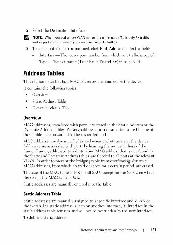
FILE LOCATION: C:\Users\vijaya_devakumar_dev\Documents\PowerConnect\Astute\Docs for Web
D E L L C O N F I D E N T I A L – P R E L I M I N A RY 3 / 1 9 / 1 5 - F O R P R O O F O N LY
2 Select the Destination Interface.
NOTE: When you add a new VLAN mirror, the mirrored traffic is only Rx traffic (unlike port mirror in which you can also mirror Tx traffic).
3 To add an interface to be mirrored, click Edit, Add, and enter the fields:
– Interface — The source port number from which port traffic is copied.
– Type — Type of traffic (Tx or Rx or Tx and Rx) to be copied.
Address TablesThis section describes how MAC addresses are handled on the device.
It contains the following topics:
• Overview
• Static Address Table
• Dynamic Address Table
OverviewMAC addresses, associated with ports, are stored in the Static Address or the Dynamic Address tables. Packets, addressed to a destination stored in one of these tables, are forwarded to the associated port.
MAC addresses are dynamically learned when packets arrive at the device. Addresses are associated with ports by learning the source address of the frame. Frames, addressed to a destination MAC address that is not found in the Static and Dynamic Address tables, are flooded to all ports of the relevant VLAN. In order to prevent the bridging table from overflowing, dynamic MAC addresses, from which no traffic is seen for a certain period, are erased.
The size of the MAC table is 16K for all SKUs except for the X4012 on which the size of the MAC table is 32K.
Static addresses are manually entered into the table.
Static Address TableStatic addresses are manually assigned to a specific interface and VLAN on the switch. If a static address is seen on another interface, its interface in the static address table remains and will not be overridden by the new interface.
To define a static address:
Network Administration: Port Settings 167

1
FILE LOCATION: C:\Users\vijaya_devakumar_dev\Documents\PowerConnect\Astute\Docs for Web
D E L L C O N F I D E N T I A L – P R E L I M I N A R Y 3 / 1 9 / 1 5 - F O R P R O O F O N LY
1 Click Network Administration > Port Settings > Address Tables > Static Address Table.
A list of the currently-defined static addresses is displayed.
2 To add a static address, click Edit, Add.
3 Enter the following fields:
• Interface Type— Select either port or LAG interface type.
• Interface— Select a port or LAG for the entry.
• MAC Address — Enter the interface MAC address.
• VLAN ID — Check and select the VLAN ID for the port.
• Status — Select how the entry in the table will be treated. The possible options are:
• Permanent — The MAC address is never aged out of the table and, if it is saved to the Startup Configuration, it is retained after rebooting.
• Delete on Reset — The MAC address is deleted when the device is reset.
• Delete on Timeout — The MAC address is deleted when a timeout occurs.
• Secure — The MAC address is secure when the interface is in classic locked mode. To prevent Static MAC addresses from being deleted when the Ethernet device is reset, ensure that the port attached to the MAC address is locked.
Dynamic Address TableThe Dynamic Address Table contains the MAC addresses acquired by monitoring the source addresses of traffic entering the switch. When the destination address for inbound traffic is found in the database, the packets intended for that address are forwarded directly to the associated port. Otherwise, the traffic is flooded to all ports in the VLAN of the frame.
To prevent the table from overflowing and to make room for new addresses, an address is deleted from the table if no traffic is received from a dynamic MAC address for a certain period. This period of time is called the aging interval.
68 Network Administration: Port Settings

FILE LOCATION: C:\Users\vijaya_devakumar_dev\Documents\PowerConnect\Astute\Docs for Web
D E L L C O N F I D E N T I A L – P R E L I M I N A RY 3 / 1 9 / 1 5 - F O R P R O O F O N LY
To configure dynamic addresses:
1 Click Network Administration > Port Settings > Dynamic Address Table.
The current address table is displayed along with other parameters.
2 Click Edit, Add.
3 Enter Address Aging (10-630). The aging time is a value between the user-configured value and twice that value minus 1. For example, if you entered 300 seconds, the aging time is between 300 and 599 seconds.
4 To clear the table, check Clear Table.
5 To display a subset of the addresses in a particular order, enter the query criteria and sort key under Query By, and click Query. The following fields are displayed for entries matching the query criteria:
– Interface — Port or LAG associated with the MAC address.
– MAC Address — Interface MAC address.
– VLAN ID — VLAN ID in the entry.
UDLDThis section describes how the Unidirectional Link Detection (UDLD) feature.
It covers the following topics:
• Overview
• UDLD Global Settings
• UDLD Interface Settings
• UDLD Neighbors
OverviewUnidirectional Link Detection (UDLD) is a Layer 2-protocol that enables devices connected through fiber-optic or twisted-pair Ethernet cables to detect unidirectional links. A unidirectional link occurs whenever traffic from a neighboring device is received by the local device, but traffic from the local device is not received by the neighbor.
Network Administration: Port Settings 169

1
FILE LOCATION: C:\Users\vijaya_devakumar_dev\Documents\PowerConnect\Astute\Docs for Web
D E L L C O N F I D E N T I A L – P R E L I M I N A R Y 3 / 1 9 / 1 5 - F O R P R O O F O N LY
The purpose of UDLD is to detect ports on which the neighbor does not receive traffic from the local device (unidirectional link) and to shut down those ports.
All connected devices must support UDLD for the protocol to successfully detect unidirectional links. If only the local device supports UDLD, it is not possible for the device to detect the status of the link. In this case, the status of the link is set to undetermined. The user can configure whether ports in the undetermined state are shut down or merely trigger notifications.
UDLD States and ModesUnder the UDLD protocol, ports are assigned the following states:
• Detection—System is attempting to determine whether the link is bidirectional or unidirectional. This is a temporary state.
• Bidirectional—Traffic sent by a local device is known to be received by its neighbor, and traffic from the neighbor is received by the local device.
• Shutdown—The link is unidirectional. Traffic sent by a local device is received by its neighbor, but traffic from the neighbor is not received by the local device.
• Undetermined—The system cannot determine the state of the port, because of one of the following is occurring:
– The neighbor does not support UDLD.
or
– The neighbor does not receive traffic from the local device.
The UDLD action in this case depends on the UDLD mode of the device as explained below.
UDLD supports the following modes of operation:
• Normal
– If the link is unidirectional, the port is shut down.
– If the link is undetermined, the port is not shut down. Its status is changed to undetermined and a notification is sent.
• Aggressive
If the link is unidirectional or undetermined, the port is shut down.
70 Network Administration: Port Settings

FILE LOCATION: C:\Users\vijaya_devakumar_dev\Documents\PowerConnect\Astute\Docs for Web
D E L L C O N F I D E N T I A L – P R E L I M I N A RY 3 / 1 9 / 1 5 - F O R P R O O F O N LY
UDLD is enabled on a port when one of the following occurs:
• The port is a fiber port and UDLD is enabled globally.
• The port is a copper port and you specifically enable UDLD on it.
How UDLD WorksWhen UDLD is enabled on a port, the following actions are performed:
• UDLD initiates the detection state on the port.
In this state, UDLD periodically sends messages on every active interface to all neighbors. These messages contain the device ID of all known neighbors. It sends these messages according to a user-defined message time.
• UDLD receives UDLD messages from neighboring devices. It caches these messages until the expiration time (3 times message time) has passed. If a new message is received before the expiration time, the information in that message replaces the previous one.
• When the expiration time expires, the device does the following with the information received:
– If the neighbor message contains the local device ID—The link status of the port is set to bidirectional.
– If the neighbor message does not contain the local device ID—The link status of the port is set to unidirectional, and the port is shut down.
• If UDLD messages are not received from a neighboring device during the expiration time frame, the link status of the port is sent to undetermined and the following occurs:
– Device is in normal UDLD mode: A notification is issued.
– Device is in aggressive UDLD mode. The port is shut down.
While the interface is in the bidirectional or the undetermined state, the device periodically sends a message each message time seconds. The above steps are performed over and over.
A port that was shut down can be reactivated manually in the Port Configuration page. For more information, see Reactivating a Shutdown Port.
Network Administration: Port Settings 171

1
FILE LOCATION: C:\Users\vijaya_devakumar_dev\Documents\PowerConnect\Astute\Docs for Web
D E L L C O N F I D E N T I A L – P R E L I M I N A R Y 3 / 1 9 / 1 5 - F O R P R O O F O N LY
If an interface is down and UDLD is enabled, the device removes all neighbor information and sends at least one ULDL message to the neighbors informing them that the port is down. When the port is brought up, the UDLD state is changed to detection.
UDLD Not Supported or is Disabled on a NeighborIf UDLD is not supported or disabled on a neighbor, then no UDLD messages are received from that neighbor. In this case, the device cannot determine whether the link is unidirectional or bidirectional. The status of the interface is then set to undetermined. The actions taken by the device depend on whether the UDLD mode is normal or aggressive.
Inconsistent UDLD Mode in Local and Neighboring DeviceIt is possible for the local device and its neighbor to be set to a different UDLD mode (normal, aggressive). The UDLD mode is not contained in the UDLD messages, so that the local device does not know the UDLD mode of the neighbor and vice versa.
If the UDLD modes are different on the local and neighbor devices, the devices act as follows:
• When the UDLD state of the link is bidirectional or unidirectional, both devices shut down their ports.
• When the UDLD state of the port is undetermined, the side with the normal UDLD mode merely issues a notification, while the side with the aggressive UDLD mode shuts down the port.
If both devices are in normal mode, the port is not shut down when its state is undetermined.
Reactivating a Shutdown PortYou can reactivate a port that was shut down by UDLD in one of the following ways:
• Automatically—Configure the system to automatically reactivate ports shut down by UDLD in the UDLD Interface Settings page. In this case, when a port is shut down by UDLD, it is automatically reactivated when the automatic recovery interval expires. UDLD again begins running on the port. If the link is still unidirectional, UDLD shuts it down again after the UDLD expiration time expires, for instance.
72 Network Administration: Port Settings

FILE LOCATION: C:\Users\vijaya_devakumar_dev\Documents\PowerConnect\Astute\Docs for Web
D E L L C O N F I D E N T I A L – P R E L I M I N A RY 3 / 1 9 / 1 5 - F O R P R O O F O N LY
• Manually—Reactivate a port in the Port Configuration page.
Usage GuidelinesDell does not recommend enabling UDLD on ports that are connected to devices on which UDLD is not supported or disabled. Sending UDLD packets on a port connected to a device that does not support UDLD simply causes more traffic on the port without providing benefits.
In addition, take the following into consideration when configuring UDLD:
• Set the message time according to how urgent it is to shut down ports with a unidirectional link. The lower the message time, the more UDLD packets are sent and analyzed, but the sooner the port is shut down if the link is unidirectional.
• If you want UDLD to be enabled on a copper port, you must enable it per port. When you globally enable UDLD, it is only enabled on fiber ports.
• Set the UDLD mode to normal when you do not want to shut down ports unless it is known for sure that the link is unidirectional.
• Set the UDLD mode to aggressive when you want to shut down any port whenever there is even a chance that the link is undetermined.
Dependencies On Other Features• UDLD and Layer 1.
When UDLD is enabled on a port, UDLD actively runs on that port while the port is up. When the port is down, UDLD goes into UDLD shutdown state. In this state, UDLD removes all learned neighbors. When the port is changed from down to up, UDLD resumes actively running.
• UDLD and Layer 2 Protocols
UDLD runs on a port independently from other Layer 2 protocols running on the same port, such as STP or LACP. For example, UDLD assigns the port a status regardless of the STP status of the port or regardless of whether the port belongs to a LAG or not.
Default Settings and ConfigurationThe following defaults exist for this feature:
• UDLD is disabled by default on all ports of the device.
Network Administration: Port Settings 173

1
FILE LOCATION: C:\Users\vijaya_devakumar_dev\Documents\PowerConnect\Astute\Docs for Web
D E L L C O N F I D E N T I A L – P R E L I M I N A R Y 3 / 1 9 / 1 5 - F O R P R O O F O N LY
• Default message time is 15 seconds.
• Default expiration time is 45 seconds (3 times the message time).
• Default port UDLD state:
– Fiber interfaces are in the global UDLD state.
– Non-fiber interfaces are in the disable state.
Common UDLD TasksThis section describes some common tasks to setup UDLD.
Workflow1: To globally enable UDLD on fiber ports, perform the following steps:
• Open the UDLD Global Settings page.
– Enter the Message Time.
– Select either Disabled, Normal or Aggressive as the global UDLD status.
– Click Apply
Workflow2: To change the UDLD configuration of a fiber port or to enable UDLD on a copper port, perform the following steps:
1 Open the UDLD Global Settings page.
• Select a port.
• Select either Default, Disabled, Normal or Aggressive as the port’s UDLD status. If you select Default, the port receives the global setting.
2 Click Apply.
UDLD Global SettingsThe UDLD feature can be configured for all fiber ports at one time (in the UDLD Global Settings page) or per port (in the UDLD Interface Settings page).
The Fiber Port UDLD Default State is only applicable to fiber ports.
The Message Time field is applicable to both copper and fiber ports.
To configure UDLD globally:
74 Network Administration: Port Settings

FILE LOCATION: C:\Users\vijaya_devakumar_dev\Documents\PowerConnect\Astute\Docs for Web
D E L L C O N F I D E N T I A L – P R E L I M I N A RY 3 / 1 9 / 1 5 - F O R P R O O F O N LY
1 Click Network Administration > Port Settings > Unidirectional Link Detection (UDLD) > UDLD Global Settings.
2 Click Edit and enter the following fields:
– Message Interval—Enter the timeout interval between two sent UDLD messages. This field is relevant for both fiber and copper ports.
– Fiber Port UDLD Default State—This field is only relevant for fiber ports. The UDLD state of copper ports must be set individually in the UDLD Interface Settings page. The possible states are:
• Disabled—UDLD is disabled on all ports of the device.
• Normal—Device shuts down an interface if the link is unidirectional. If the link is undetermined, a notification is issued.
• Aggressive—Device shuts down an interface if the link is unidirectional or undetermined.
UDLD Interface SettingsUse the UDLD Interface Settings page to change the UDLD state for a specific port. Here the state can be set for copper or fiber ports.
To copy a particular set of values to more than one port, set that value for one port and use the Copy button to copy it to the other ports.
To configure UDLD for an interface:
1 Click Network Administration > Port Settings > Unidirectional Link Detection (UDLD) > UDLD Interface Settings.
Information is displayed for all ports on which UDLD is enabled, or, if you have filtered only a certain group of ports, information is displayed for that group of ports.
– Port—The port identifier.
– UDLD State—The possible states are:
• Default — State defined as default in UDLD Global Settings.
• Disabled — UDLD is disabled on all fiber ports of the device.
• Normal — Device shuts down an interface if it detects that the link is unidirectional. It issues a notification if the link is undetermined.
Network Administration: Port Settings 175

1
FILE LOCATION: C:\Users\vijaya_devakumar_dev\Documents\PowerConnect\Astute\Docs for Web
D E L L C O N F I D E N T I A L – P R E L I M I N A R Y 3 / 1 9 / 1 5 - F O R P R O O F O N LY
• Aggressive — Device shuts down a port if the link is unidirectional or undetermined.
– Bidirectional State — Bidirectional state for the selected port. The possible states are:
• Detection — The latest UDLD state of the port is in the process of being determined. Expiration time has not yet expired since the last determination (if there was one), or since UDLD began running on the port, so that the state is not yet determined.
• Bidirectional—Traffic sent by the local device is received by its neighbor, and traffic from the neighbor is received by the local device.
• Undetermined — The state of the link between the port and its connected port cannot be determined either because no UDLD message was received or the UDLD message did not contain the local device ID in it.
• Disabled — UDLD has been disabled on this port.
• Shutdown — The port has been shut down because its link with the connected device is unidirectional or undetermined in aggressive mode.
– Number of Neighbors — Number of connected devices detected.
2 To modify the UDLD state for a specific port, click its Edit icon and select the port.
3 Modify the value of the UDLD state. If you select Default, the port receives the value of the Fiber Port UDLD Default State in the UDLD Global Settings page.
UDLD NeighborsTo view all devices connected to the local device:
1 Click Network Administration > Port Settings > UDLD Neighbors.
The following fields are displayed for all UDLD-enabled ports.
– Interface Name — Name of the local UDLD-enabled port.
– Device ID — ID of the remote device.
– Device MAC — MAC address of the remote device.
76 Network Administration: Port Settings

FILE LOCATION: C:\Users\vijaya_devakumar_dev\Documents\PowerConnect\Astute\Docs for Web
D E L L C O N F I D E N T I A L – P R E L I M I N A RY 3 / 1 9 / 1 5 - F O R P R O O F O N LY
– Device Name — Name of the remote device.
– Port ID — Name of the remote port.
– State — State of the link between the local and neighboring device on the local port. The following values are possible:
• Detection — The latest UDLD state of the port is in the process of being determined. Expiration time has not yet expired since the last determination (if there was one), or since UDLD began running on the port, so that the state is not yet determined.
• Bidirectional — Traffic sent by the local device is received by its neighbor, and traffic from the neighbor is received by the local device.
• Undetermined — The state of the link between the port and its connected port cannot be determined either because no UDLD message was received or the UDLD message did not contain the local device ID in it.
• Disabled — UDLD has been disabled on this port.
• Shutdown — The port has been shut down because its link with the connected device is unidirectional or undetermined in aggressive mode.
– Neighbor Expiration Time (Sec.) — Displays the time that must pass before determining the port UDLD status. This is three times the Message Time.
– Neighbor Message Time (Sec.) — Displays the time between UDLD messages.
Network Administration: Port Settings 177

1
FILE LOCATION: C:\Users\vijaya_devakumar_dev\Documents\PowerConnect\Astute\Docs for Web
D E L L C O N F I D E N T I A L – P R E L I M I N A R Y 3 / 1 9 / 1 5 - F O R P R O O F O N LY
78 Network Administration: Port Settings

FILE LOCATION: C:\Users\vijaya_devakumar_dev\Documents\PowerConnect\Astute\Docs for Web Posting\Astute_Admin_Guide_sources_MIF7\FM\Dell_Astute_Network_Admin_STP.fm
D E L L C O N F I D E N T I A L – P R E L I M I N A RY 3 / 1 9 / 1 5 - F O R P R O O F O N LY
11Network Administration: Spanning Tree and LAGThis chapter covers the following topics:
• Spanning Tree
• Link Aggregation (LAG)
Spanning TreeThis section: describes how to configure the Spanning Tree feature. It contains the following topics:
• Global Settings
• STP Port Settings
• Rapid Spanning Tree
• MSTP Properties
• VLAN to MSTP Instance
• MSTP Instance Settings
• MSTP Interface Settings
Spanning Tree OverviewSpanning Tree Protocol (STP) provides tree topography for any bridge arrangement. STP eliminates loops by providing a unique path between end stations on a network.
Loops occur when alternate paths exist between hosts. Loops can cause bridges to relay the same packet(s) indefinitely, resulting in packets not arriving at their destination, Broadcast/Multicast storms, and reduced network efficiency.
Network Administration: Spanning Tree and LAG 179

1
FILE LOCATION: C:\Users\vijaya_devakumar_dev\Documents\PowerConnect\Astute\Docs for Web Posting\Astute_Admin_Guide_sources_MIF7\FM\Dell_Astute_Network_Admin_STP.fm
D E L L C O N F I D E N T I A L – P R E L I M I N A R Y 3 / 1 9 / 1 5 - F O R P R O O F O N LY
The device supports the following Spanning Tree versions:
• Classic STP — Provides a single path between end stations, avoiding and eliminating loops. For more information on configuring Classic STP, see "Global Settings" on page 181.
• Rapid STP (RSTP) — Provides faster convergence of the spanning tree than Classic STP. RSTP is most effective when the network topology is naturally tree-structured, and therefore faster convergence might be possible. RSTP is enabled by default.
Although Classic STP is guaranteed to prevent Layer 2 forwarding loops, in a general network topology, there might be an unacceptable delay before convergence. This means that before convergence, each bridge or switch in the network must decide if it should actively forward traffic or not, on each of its ports.
For more information on configuring Rapid STP, see "Rapid Spanning Tree" on page 185.
• Multiple STP (MSTP) — MSTP is based on RSTP. It detects Layer 2 loops, and attempts to mitigate them by preventing the involved port from transmitting traffic.
Since loops exist on a per-Layer 2-domain basis, a situation occurs when a port is blocked to eliminate a STP loop. Traffic will be forwarded to the port that is not blocked, and no traffic will be forwarded to the port that is blocked. This is not an efficient usage of bandwidth as the blocked port will always be unused.
Multiple Spanning Tree Protocol (MSTP) solves this problem by enabling several STP instances, so that it is possible to detect and mitigate loops separately in each instance. This enables a port to be blocked for one or more STP instances but not blocked for other STP instances. If different VLANs are associated with different STP instances, then their traffic is relayed based on the STP port state of their associated MST instances. Better bandwidth utilization is resulted.
An MST region consists of adjacent MSTP bridges that have the same VLANs to MST instances association. If there are a mixed of STP/RSTP/MSTP bridges and/or multiple MST regions in a LAN, each MST region in the LAN is treated as a single STP/RSTP bridge. And MST regions are independent.
80 Network Administration: Spanning Tree and LAG

FILE LOCATION: C:\Users\vijaya_devakumar_dev\Documents\PowerConnect\Astute\Docs for Web Posting\Astute_Admin_Guide_sources_MIF7\FM\Dell_Astute_Network_Admin_STP.fm
D E L L C O N F I D E N T I A L – P R E L I M I N A RY 3 / 1 9 / 1 5 - F O R P R O O F O N LY
MST region appears as a single bridge.
For more information on configuring Multiple STP, see "MSTP Properties" on page 187.
Global SettingsTo enable STP and select the STP mode on the device:
1 Click Network Administration > Spanning Tree and LAG > Spanning Tree > Global Settings.
The currently-defined settings are displayed.
2 Click Edit and enter the fields:
– Spanning Tree State — Enable Spanning Tree on the device.
– STP Operation Mode — Select the STP mode enabled on the device. The possible options are:
• Classic STP — Enables Classic STP on the device.
• Rapid STP — Enables Rapid STP on the device. This is the default value.
• Multiple STP — Enables Multiple STP on the device.
– BPDU Handling — Select how Bridge Protocol Data Unit (BPDU) packets are managed when STP is disabled on the port/device. BPDUs are used to transmit spanning tree information. The possible options are:
• Filtering — Filter BPDU packets when spanning tree is disabled on an interface.
• Flooding — Flood BPDU packets when spanning tree is disabled on an interface.
– Path Cost Default Values — Select the method used to assign default path costs to STP ports. The possible options are:
• Short — Specifies 1 through 65,535 range for port path costs.
• Long — Specifies 1 through 200,000,000 range for port path costs.
Network Administration: Spanning Tree and LAG 181

1
FILE LOCATION: C:\Users\vijaya_devakumar_dev\Documents\PowerConnect\Astute\Docs for Web Posting\Astute_Admin_Guide_sources_MIF7\FM\Dell_Astute_Network_Admin_STP.fm
D E L L C O N F I D E N T I A L – P R E L I M I N A R Y 3 / 1 9 / 1 5 - F O R P R O O F O N LY
The default path costs assigned to an interface vary according to the selected method:
Bridge Settings
– Priority (0-61440 in steps of 4096) — Enter the bridge priority value. When switches or bridges are running STP, each is assigned a priority. After exchanging BPDUs, the device with the lowest priority value becomes the Root Bridge. The default value is 32768. The port priority value is provided in increments of 4096. For example, 4096, 8192, 12288, etc.
– Hello Time (1-10) — Check to use the device Hello Time, which is the interval of time in seconds that a root bridge waits between configuration messages. Enter a value.
– Max Age (6-40) — Check to use device Maximum Age Time, which is the time interval in seconds that a bridge waits before sending configuration messages. Enter a value.
– Forward Delay (4-30) — Check to use device forward delay time, which is the interval of time in seconds that a bridge remains in a listening and learning state before forwarding packets. Enter a value.
Designated Root — Displays the following:
– Bridge ID — The bridge priority and MAC address.
– Root Bridge ID — The root bridge priority and MAC address.
– Root Port — The port number that offers the lowest cost path from this bridge to the Root Bridge. This is significant when the Bridge is not the Root.
– Root Path Cost — The cost of the path from this bridge to the root.
Interface Long Cost Short Cost
LAG 20,000 4
1000 Mbps 20,000 4
100 Mbps 200,000 19
10 Mbps 2,000,000 100
10 Gb 20,000 2
82 Network Administration: Spanning Tree and LAG

FILE LOCATION: C:\Users\vijaya_devakumar_dev\Documents\PowerConnect\Astute\Docs for Web Posting\Astute_Admin_Guide_sources_MIF7\FM\Dell_Astute_Network_Admin_STP.fm
D E L L C O N F I D E N T I A L – P R E L I M I N A RY 3 / 1 9 / 1 5 - F O R P R O O F O N LY
– Topology Changes Counts — The total amount of STP state changes that have occurred.
– Last Topology Change — The amount of time that has elapsed since the bridge was initialized or reset, and the last topographic change occurred.
STP Port Settings To assign STP properties to individual ports:
1 Click Network Administration > Spanning Tree and LAG > Spanning Tree > STP Port Settings.
The ports and their STP settings are displayed.
2 Click Edit.
3 Select a port, click its Edit icon and enter the fields:
– STP — Enable/disable STP on the port.
– Fast Link — Enable/disable Fast Link mode for the port. If this is enabled, the Port State is automatically placed in the Forwarding state when the port is up. Fast Link mode optimizes the time it takes for the STP protocol to converge. STP convergence can take 30-60 seconds in large networks.
– BPDU Guard — Enable/disable BPDU Guard on the port. BPDU guard when enabled shuts down a port when BPUD messages are received from the port.
– Root Guard — Enable/disable prevention of devices outside the network core from being elected as the spanning tree root bridge.
– Port State — Displays the current STP state of a port. If the port state is not disabled, it determines what forwarding action is taken on traffic. The possible port states are:
• Disabled — STP is currently disabled on the port. The port forwards traffic while learning MAC addresses.
• Blocking — The port is currently blocked and cannot be used to forward traffic or learn MAC addresses. Blocking is displayed when Classic STP is enabled.
• Listening — The port is currently in the listening mode. The port cannot forward traffic nor can it learn MAC addresses.
Network Administration: Spanning Tree and LAG 183

1
FILE LOCATION: C:\Users\vijaya_devakumar_dev\Documents\PowerConnect\Astute\Docs for Web Posting\Astute_Admin_Guide_sources_MIF7\FM\Dell_Astute_Network_Admin_STP.fm
D E L L C O N F I D E N T I A L – P R E L I M I N A R Y 3 / 1 9 / 1 5 - F O R P R O O F O N LY
• Learning — The port is currently in the learning mode. The port cannot forward traffic, however it can learn new MAC addresses.
• Forwarding — The port is currently in the forwarding mode. The port can forward traffic and learn new MAC addresses.
– Role — Displays the port role assigned by the STP algorithm that provides STP paths. The possible options are:
• Root — This port provides the lowest cost path to forward packets to root bridge.
• Designated — This port is the interface through which the bridge is connected to the LAN, which provides the lowest cost path from the LAN to the Root Bridge.
• Disabled — This port is not participating in the Spanning Tree.
– Speed — Displays the speed at which the port is operating.
– Path Cost — Enter the port contribution to the root path cost. The path cost is adjusted to a higher or lower value, and is used to forward traffic when a path being rerouted. Select Use Default to use the default path cost.
– Priority — Select the priority value that influences the port choice when a bridge has two ports connected in a loop. The priority value is provided in increments of 16.
– Designated Bridge ID — Displays the bridge priority and the MAC address of the designated bridge.
– Designated Port ID — Displays the designated port’s priority and interface.
– Designated Cost — Displays the cost of the port participating in the STP topology. Ports with a lower cost are less likely to be blocked if STP detects loops.
– Forward Transitions — Displays the number of times the port has changed from the Forwarding state to Blocking.
– LAG — Displays the LAG to which the port is attached.
84 Network Administration: Spanning Tree and LAG

FILE LOCATION: C:\Users\vijaya_devakumar_dev\Documents\PowerConnect\Astute\Docs for Web Posting\Astute_Admin_Guide_sources_MIF7\FM\Dell_Astute_Network_Admin_STP.fm
D E L L C O N F I D E N T I A L – P R E L I M I N A RY 3 / 1 9 / 1 5 - F O R P R O O F O N LY
Rapid Spanning Tree While classic spanning tree prevents Layer 2 forwarding loops on a general network topology, convergence can take from 30 to 60 seconds. This delay provides time to detect possible loops, and propagate status changes.
Rapid Spanning Tree Protocol (RSTP) detects and uses network topologies that enable a faster convergence of the spanning tree, without creating forwarding loops.
To configure RSTP:
1 Click Network Administration > Spanning Tree and LAG > Spanning Tree > Rapid Spanning Tree.
2 Select either Ports or LAGs from the View By dropdown menu.
3 Click Edit, select an interface, click its Edit icon and enter the fields:
– Interface — Displays the port or LAG selected.
– State — Displays the RSTP state of the selected interface.
– Role — Displays the port role assigned by the STP algorithm in order to provide STP paths. The possible options are:
• Root — This port provides the lowest cost path to forward packets to root bridge.
• Designated — This port is the interface through which the bridge is connected to the LAN, which provides the lowest cost path from the LAN to the Root Bridge.
• Alternate — This port provides an alternate path to the root bridge from the root port.
• Backup — This port provides a backup path to the designated port. Backup ports occur only when two ports are connected in a loop by a point-to-point link. Backup ports also occur when a LAN has two or more connections connected to a shared segment.
• Disabled — This port is not participating in the Spanning Tree.
– Mode — Displays if RSTP is enabled.
– Fast Link Operational Status — Displays if Fast Link is enabled or disabled for the port or LAG. If Fast Link is enabled for an interface, the interface is automatically placed in the forwarding state. The possible options are:
Network Administration: Spanning Tree and LAG 185

1
FILE LOCATION: C:\Users\vijaya_devakumar_dev\Documents\PowerConnect\Astute\Docs for Web Posting\Astute_Admin_Guide_sources_MIF7\FM\Dell_Astute_Network_Admin_STP.fm
D E L L C O N F I D E N T I A L – P R E L I M I N A R Y 3 / 1 9 / 1 5 - F O R P R O O F O N LY
• Enable — Fast Link is enabled.
• Disable — Fast Link is disabled.
• Auto — Fast Link mode is enabled a few seconds after the interface becomes active.
– Point-to-Point Admin Status — Select if a point-to-point links is established, or permits the device to establish a point-to-point link. The possible options are:
• Enabled — Enables the device to establish a point-to-point link, or specifies for the device to automatically establish a point-to-point link. To establish communications over a point-to-point link, the originating PPP first sends Link Control Protocol (LCP) packets to configure and test the data link. After a link is established and optional facilities are negotiated as needed by the LCP, the originating PPP sends Network Control Protocols (NCP) packets to select and configure one or more network layer protocols. When each of the chosen network layer protocols has been configured, packets from each network layer protocol can be sent over the link. The link remains configured for communications until explicit LCP or NCP packets close the link, or until some external event occurs. This is the actual switch port link type. It may differ from the administrative state.
• Disabled — Disables point-to-point link.
• Auto — The device automatically establishes a point-to-point link.
– Point-to-Point Operational Status — Displays the Point-to-Point operating state.
– Active Protocol Migration Test — Check to run a Protocol Migration test. This discovers whether the link partner using STP still exists, and if so whether it has migrated to RSTP or MSTP. If it still exists as an STP link, the device continues to communicate with it by using STP. Otherwise, if it has been migrated to RSTP or MSTP, the device communicates with it using RSTP or MSTP, respectively.
86 Network Administration: Spanning Tree and LAG

FILE LOCATION: C:\Users\vijaya_devakumar_dev\Documents\PowerConnect\Astute\Docs for Web Posting\Astute_Admin_Guide_sources_MIF7\FM\Dell_Astute_Network_Admin_STP.fm
D E L L C O N F I D E N T I A L – P R E L I M I N A RY 3 / 1 9 / 1 5 - F O R P R O O F O N LY
MSTP PropertiesMSTP maps VLANs into MSTP instances, using various load balancing scenarios. As a result of this partitioning into instances, a port can be placed in Blocking State in one STP instance and can be placed in the Forwarding State in another STP instance.
Packets are transmitted along the MSTP instances that their VLANs are associated with in a Multiple Spanning Tree Region. A MST region consists of adjacent MSTP bridges that have the same VLANs to MST instances association.
To set an MSTP region:
1 Click Network Administration > Spanning Tree and LAG > Spanning Tree > MSTP Properties.
2 Click Edit and enter the following fields:
– Region Name — Enter the user-defined MSTP region name.
– Revision — Enter the unsigned 16-bit number that identifies the current MST configuration revision. The revision number is required as part of the MST configuration.
– Max Hops (1-40) — Enter the total number of hops that occur in a specific region before the BPDU is discarded. Once the BPDU is discarded, the port information is aged out.
– IST Master — Displays the Internal Spanning Tree Master ID. The IST Master is the instance 0 root.
VLAN to MSTP InstanceTo map VLANs to MSTP instances:
1 Click Network Administration > Spanning Tree and LAG > Spanning Tree > VLAN to MSTP Instance.
The MSTP instances and their associated VLANs are displayed.
2 Click Edit.
3 Select the MSTP instance and click its Edit icon.
4 Enter the fields:
– VLANs — Enter the VLANs being mapped to this instance.
– Action — Select the mapping action. The possible options are:
Network Administration: Spanning Tree and LAG 187

1
FILE LOCATION: C:\Users\vijaya_devakumar_dev\Documents\PowerConnect\Astute\Docs for Web Posting\Astute_Admin_Guide_sources_MIF7\FM\Dell_Astute_Network_Admin_STP.fm
D E L L C O N F I D E N T I A L – P R E L I M I N A R Y 3 / 1 9 / 1 5 - F O R P R O O F O N LY
• Add — Add these VLANS to the MST instance.
• Remove — Remove these VLANS from the MST instance.
MSTP Instance SettingsTo configure MSTP instances:
1 Click Network Administration > Spanning Tree and LAG > MSTP Instance Settings.
The MSTP instances and their associated VLANs are displayed.
2 Select an Instance ID.
3 Enter the Bridge Priority (0-61440) of this bridge for the selected MSTP instance.
4 The following fields are displayed:
– Included VLANs — Displays VLANs included in this instance.
– Designated Root Bridge ID — Priority and MAC address of the Root Bridge for the MST instance.
– Root Port — Root port of the selected instance.
– Root Path Cost — Root path cost of the selected instance.
– Bridge ID — Bridge priority and the MAC address of this switch for the selected instance.
– Remaining Hops — Number of hops remaining to the next destination.
MSTP Interface SettingsTo assign interfaces to MSTP instances:
1 Click Network Administration > Spanning Tree and LAG > Spanning Tree > MSTP Interface Settings.
MSTP interface settings for the selected instance is displayed.
2 Click Edit.
3 Select an instance, and enter the fields:
– Interface — Assign either ports or LAGs to the selected MSTP instance.
88 Network Administration: Spanning Tree and LAG

FILE LOCATION: C:\Users\vijaya_devakumar_dev\Documents\PowerConnect\Astute\Docs for Web Posting\Astute_Admin_Guide_sources_MIF7\FM\Dell_Astute_Network_Admin_STP.fm
D E L L C O N F I D E N T I A L – P R E L I M I N A RY 3 / 1 9 / 1 5 - F O R P R O O F O N LY
– Port State — Displays whether the port is enabled or disabled in the specific instance.
– Type — Displays whether MSTP treats the port as a point-to-point port, or a port connected to a hub, and whether the port is internal to the MST region or a boundary port. A Master port provides connectivity from a MSTP region to the outlying CIST root. A Boundary port attaches MST bridges to LAN in an outlying region. If the port is a boundary port, it also indicates whether the device on the other side of the link is working in RSTP or STP mode.
– Role — Displays the port role assigned by the STP algorithm in order to provide to STP paths. The possible options are:
• Root — This port provides the lowest cost path to forward packets to root switch.
• Designated — This port is the interface through which the bridge is connected to the LAN, which provides the lowest cost path from the LAN to the Root Bridge.
• Alternate — This port provides an alternate LAG to the root switch from the root interface.
• Backup — This port provides a backup path to the designated port. Backup ports occur only when two ports are connected in a loop by a point-to-point link. Backup ports also occur when a LAN has two or more connections connected to a shared segment.
• Disabled — This port is not participating in the Spanning Tree.
– Interface Priority — Enter the interface priority for specified instance.
– Path Cost — Enter the port contribution to the Spanning Tree instance. If a loop occurs, the spanning tree considers path cost when selecting an interface to put in the Forwarding state or select Use Default.
– Designated Bridge ID — Displays the bridge ID number that connects the link or shared LAN to the root.
– Designated Port ID — Displays the Port ID number on the designated bridge that connects the link or the shared LAN to the root.
– Designated Cost — Displays the cost of the path from the link or the shared LAN to the root.
Network Administration: Spanning Tree and LAG 189

1
FILE LOCATION: C:\Users\vijaya_devakumar_dev\Documents\PowerConnect\Astute\Docs for Web Posting\Astute_Admin_Guide_sources_MIF7\FM\Dell_Astute_Network_Admin_STP.fm
D E L L C O N F I D E N T I A L – P R E L I M I N A R Y 3 / 1 9 / 1 5 - F O R P R O O F O N LY
– Forward Transitions — Displays the number of times the port changed to the forwarding state.
– Remain Hops — Displays the number of hops remaining to the next destination.
Link Aggregation (LAG)This section describes link aggregation of ports.
It contains the following topics:
• Overview
• LAG Membership
• LAG Configuration
• LACP Parameters
• VLAN LAG Membership
• VLAN LAG Settings
• STP LAG Settings
OverviewLink Aggregation optimizes port usage by linking a group of ports together to form a single Link Aggregation Group (LAG). Aggregating ports multiplies the bandwidth between two devices, increases port flexibility, and provides link redundancy.
The device supports the following types of LAGs:
• Static LAGs — Manually-configured LAGs.
• Link Aggregation Control Protocol (LACP) LAGs — LACP LAGs negotiate aggregating a port’s links with other LACP ports located on a different device. If the other device ports are also LACP ports, the devices establishes a LAG between them.
When you aggregate ports, the ports and LAG must fulfill the following conditions:
• All ports within a LAG must be the same media type.
• A VLAN is not configured on the port.
• The port is not assigned to another LAG.
90 Network Administration: Spanning Tree and LAG
FILE LOCATION: C:\Users\vijaya_devakumar_dev\Documents\PowerConnect\Astute\Docs for Web Posting\Astute_Admin_Guide_sources_MIF7\FM\Dell_Astute_Network_Admin_STP.fm
D E L L C O N F I D E N T I A L – P R E L I M I N A RY 3 / 1 9 / 1 5 - F O R P R O O F O N LY
• Auto-negotiation mode is not configured on the port.
• The port is in full-duplex mode.
• All ports in the LAG have the same ingress filtering and tagged modes.
• All ports in the LAG have the same back pressure and flow control modes.
• All ports in the LAG have the same priority.
• All ports in the LAG have the same transceiver type.
• The device supports up to 12 LAGs, and eight ports in each LAG.
• Ports can be configured as LACP ports only if the ports are not part of a previously configured LAG.
Ports added to a LAG lose their individual port configuration. When ports are removed from the LAG, the original port configuration is applied to the ports.
The device uses a hash function to assign packets to a LAG member. The hash function statistically load-balances the aggregated link members. The device considers a LAG to be a single logical port.
Aggregate ports can be linked into link-aggregation port-groups. Each group comprises ports with the same speed, set to full-duplex operations.
LAG MembershipEach device supports up to 12 LAGs per system, and eight ports per LAG.
When you add a port to a LAG, the port acquires the LAG’s properties. If the port cannot be configured with the LAG’s properties, it is not added to the LAG and an error message is generated.
If the first port joining the LAG cannot be configured with the LAG settings, the port is added to the LAG, using the port default settings, and an error message is generated. Since this is the only port in the LAG, the entire LAG operates with the port’s settings, instead of the LAG’s defined settings.
To manually select ports that comprise a LAG:
1 Click Network Administration > Spanning Tree and LAG > Link Aggregation (LAG) > LAG Membership.
The LACP parameters for all ports are displayed.
2 Click Edit.
3 Select a LAG.
Network Administration: Spanning Tree and LAG 191

1
FILE LOCATION: C:\Users\vijaya_devakumar_dev\Documents\PowerConnect\Astute\Docs for Web Posting\Astute_Admin_Guide_sources_MIF7\FM\Dell_Astute_Network_Admin_STP.fm
D E L L C O N F I D E N T I A L – P R E L I M I N A R Y 3 / 1 9 / 1 5 - F O R P R O O F O N LY
4 Select whether it is a Standard (user-defined LAG) or an LACP-defined LAG.
5 Click on the ports that will comprise the LAG.
LAG ConfigurationUse the LAG Configuration pages to configure LAGs. The device supports up to 12 LAGs per system.
To set various configuration parameters for LAGs:
1 Click Network Administration > Spanning Tree and LAG > Link Aggregation (LAG) > LAG Configuration.
The LAG parameters are displayed.
2 Click Edit.
3 Select the LAG, click its Edit icon and enter the fields:
– LAG Mode — Select the LAG mode. The possible options are:
• Static — The ports in the LAG are manually configured.
• LACP — When enabled, the device exchanges LACP messages with its neighbors to update and maintain LAG configurations automatically.
– Description — Enter a user-defined description of the configured LAG.
– LAG Type — Displays the port types that comprise the LAG.
– Admin Status — Enable/disable the selected LAG.
– Current Status — Displays the LAG is currently operating.
– Admin Speed — Select the configured speed at which the ports in the LAG will operate. The possible options are:
• 10M — The ports are currently operating at 10 Mbps.
• 100M — The ports are currently operating at 100 Mbps.
• 1000M — The ports are currently operating at 1000 Mbps.
– Current Speed — Displays the speed at which the ports in the LAG are currently operating.
92 Network Administration: Spanning Tree and LAG

FILE LOCATION: C:\Users\vijaya_devakumar_dev\Documents\PowerConnect\Astute\Docs for Web Posting\Astute_Admin_Guide_sources_MIF7\FM\Dell_Astute_Network_Admin_STP.fm
D E L L C O N F I D E N T I A L – P R E L I M I N A RY 3 / 1 9 / 1 5 - F O R P R O O F O N LY
– Admin Auto Negotiation — Enable/disable auto-negotiation, which is a protocol between two link partners that enables a LAG to advertise its transmission rate, duplex mode and flow control abilities to its partner.
– Current Auto Negotiation — Displays the current auto-negotiation setting.
– Admin Advertisement — If auto-negotiation is enabled, select the auto-negotiation setting the LAG advertises. The possible options are:
• Max Capability — All LAG speeds and Duplex mode settings are accepted.
• 10 F — The LAG advertises for a 10 Mbps speed LAG and full duplex mode setting.
• 100 F — The LAG advertises for a 100 Mbps speed LAG and full duplex mode setting.
• 1000 F — The LAG advertises for a 1000 Mbps speed LAG and full duplex mode setting.
– Current Advertisement — Displays the speed that the LAG advertises to its neighbor LAG to start the negotiation process. The possible field values are those specified in the Admin Advertisement field.
– Neighbor Advertisement — Displays the neighboring LAG advertisement settings. The field values are identical to the Admin Advertisement field values.
– Admin Flow Control — Enable/disable flow control on the LAG. Flow Control mode is effective on the ports operating in Full Duplex in the LAG. The possible options are:
• Enable — Enables flow control on the LAG (default).
• Disable — Disables flow control on the LAG.
• Auto Negotiation — Enables the auto-negotiation of flow control on the LAG.
– Current Flow Control — Displays the current Flow Control setting.
LACP Parameters Configuring LACP LAGs involves configuring LACP global and port parameters, such as LACP system priority, timeout, and port priority.
Network Administration: Spanning Tree and LAG 193

1
FILE LOCATION: C:\Users\vijaya_devakumar_dev\Documents\PowerConnect\Astute\Docs for Web Posting\Astute_Admin_Guide_sources_MIF7\FM\Dell_Astute_Network_Admin_STP.fm
D E L L C O N F I D E N T I A L – P R E L I M I N A R Y 3 / 1 9 / 1 5 - F O R P R O O F O N LY
With all factors equal, when the LAG is configured with more candidate ports than the maximum number of active ports allowed, the switch activates the highest priority candidate ports from the dynamic LAG.
To configure LACP parameters:
1 Click Network Administration > Spanning Tree and LAG > Link Aggregation (LAG) > LACP Parameters.
The LACP parameters for all ports are displayed.
2 Click Edit, Settings Icon ( ) and enter the global LACP System Priority value that determines which candidate ports will become members of the LAG.
The page displays the LACP settings of the ports.
3 To modify LACP parameters for a particular port, click Edit, select a port and enter the following fields:
– Port — Displays the port for which timeout and priority values are assigned.
– LACP Port Priority — Enter the LACP priority value for the port. If this value is not entered, the global default is used.
– LACP Timeout — Select the rate of periodic transmissions of LACP PDUs. The possible options are:
• Long — Slow transmission rate
• Short — Fast transmission rate
VLAN LAG Membership To view LAGs assigned to a VLAN: (though the VLAN LAG Membership page)
1 Click Network Administration > Spanning Tree and LAG > Link Aggregation (LAG) VLAN LAG Membership.
2 Select a VLAN and click Edit.
The LAGs assigned to the selected VLAN are displayed along with the following fields:
– VLAN Name — Name of VLAN selected.
– Status — User defined or LACP defined
94 Network Administration: Spanning Tree and LAG

FILE LOCATION: C:\Users\vijaya_devakumar_dev\Documents\PowerConnect\Astute\Docs for Web Posting\Astute_Admin_Guide_sources_MIF7\FM\Dell_Astute_Network_Admin_STP.fm
D E L L C O N F I D E N T I A L – P R E L I M I N A RY 3 / 1 9 / 1 5 - F O R P R O O F O N LY
– Authentication Not Required — Whether authentication is enabled on the VLAN.
VLAN LAG SettingsVLANs can either be composed of individual ports or of LAGs. Untagged packets entering the device are tagged with the LAGs ID specified by the PVID.
To assign LAGs to a VLAN:
1 Click Network Administration > Spanning Tree and LAG > Link Aggregation (LAG) > VLAN LAG Settings.
All LAGs and their settings are displayed.
2 Click Edit, select a LAG, click its Edit icon and enter the fields:
– LAG — Displays the LAG to be modified.
– Switchport Mode — Enter the LAG system mode. The possible options are:
• Layer 2 — Set the LAG to layer 2 mode.
• Layer 3 — Set the LAG to layer 3 mode. in which static routing is supported.
– Port VLAN Mode — Enter the port VLAN mode. The possible options are:
• General — The port belongs to VLANs, and each VLAN is user-defined as tagged or untagged (full 802.1Q mode).
• Access — The port belongs to a single untagged VLAN. When a port is in Access mode, the frame types that are accepted on the port cannot be designated. Ingress filtering cannot be enabled/disabled on an access port.
• Trunk — The port belongs to VLANs on which all ports are tagged (except for one port that can be untagged).
• Customer — When a port is in Customer mode, an added tag provides a VLAN ID to each customer, ensuring private and segregated network traffic for that customer.
• Private VLAN Promiscuous — The port is a promiscuous port.
• Private VLAN Host — The port is an isolated port
Network Administration: Spanning Tree and LAG 195

1
FILE LOCATION: C:\Users\vijaya_devakumar_dev\Documents\PowerConnect\Astute\Docs for Web Posting\Astute_Admin_Guide_sources_MIF7\FM\Dell_Astute_Network_Admin_STP.fm
D E L L C O N F I D E N T I A L – P R E L I M I N A R Y 3 / 1 9 / 1 5 - F O R P R O O F O N LY
– Current Reserved VLAN — Displays the VLAN currently designated as the reserved VLAN.
– Reserve VLAN for Internal Use (1-4094) — Enter the VLAN that will be used when assigning IP Address on a port, or select None.
– PVID — Assigns a VLAN ID to untagged packets. The possible VLAN IDs are 1-4095. VLAN 4095 is defined as per standard and industry practice, as the discard VLAN. Packets classified to this VLAN are dropped.
– VLAN List — Enter the VLAN(s) to which this LAG belongs.
Click Add/Remove to move the LAG to the VLAN list together with its type.
NOTE: In Access mode, a port can only be a member in a single VLAN, so before adding an access port to the VLAN, the VLAN the port is currently a member in should be manually removed (by selecting it from the VLAN list and clicking the remove button).
– Membership — Packet tagging on VLAN. The possible options are:
• Tagged — The LAG is a member of a VLAN. All packets forwarded to the LAG are tagged. The packets contain VLAN information.
• Untagged — The LAG is a member of a VLAN. Packets forwarded to the LAG are untagged.
• Forbidden — The LAG is denied membership to a VLAN.
– Frame Type — Packet type accepted by the LAG. The possible options are:
• Admit All — Tagged and untagged packets are both accepted by the LAG.
• Admit Tagged Only — Only tagged packets are accepted by the LAG.
• Admit Untagged Only — Only untagged packets are accepted on the LAG.
– Ingress Filtering — Enable/disable Ingress filtering by the LAG. Ingress filtering discards packets that are destined to VLANs of which the specific LAG is not a member.
96 Network Administration: Spanning Tree and LAG

FILE LOCATION: C:\Users\vijaya_devakumar_dev\Documents\PowerConnect\Astute\Docs for Web Posting\Astute_Admin_Guide_sources_MIF7\FM\Dell_Astute_Network_Admin_STP.fm
D E L L C O N F I D E N T I A L – P R E L I M I N A RY 3 / 1 9 / 1 5 - F O R P R O O F O N LY
– Native VLAN ID — Enter VLAN used for untagged traffic to trunk ports, or select None.
– Multicast VLAN ID — Enter VLAN used for Multicast TV VLAN traffic on access ports, or select None.
– Customer VLAN ID — Enter VLAN used for customer ports, or select None.
STP LAG Settings To assign STP parameters to LAGs:
1 Click Network Administration > Spanning Tree and LAG > Link Aggregation (LAG) > STP LAG Settings.
The LAGs and their STP settings are displayed.
2 Click Edit, select a LAG and click its Edit icon.
3 Enter the fields.
– LAG — Displays the LAG being configured.
– STP — Enable/disable STP on the LAG.
– Fast Link — Enable/disable Fast Link mode for the LAG. If Fast Link mode is enabled for a LAG, the LAG State is automatically placed in Forwarding when the LAG is up. Fast Link mode optimizes the time it takes for the STP protocol to converge. STP convergence can take from 30-60 seconds in large networks.
– BPDU Guard — Enable/disable BPDU Guard on the LAG.
– Root Guard — Enable/disable prevention of devices outside the network core from being assigned the spanning tree root bridge.
– LAG State — Displays the current STP state of the LAG. If enabled, the LAG state determines what forwarding action is taken on traffic. If the bridge discovers a malfunctioning LAG, the LAG is placed in the Broken state. Possible LAG states are:
• Disabled — STP is currently disabled on the LAG. The LAG forwards traffic while learning MAC addresses.
• Blocking — The LAG is blocked and cannot be used to forward traffic or learn MAC addresses.
Network Administration: Spanning Tree and LAG 197

1
FILE LOCATION: C:\Users\vijaya_devakumar_dev\Documents\PowerConnect\Astute\Docs for Web Posting\Astute_Admin_Guide_sources_MIF7\FM\Dell_Astute_Network_Admin_STP.fm
D E L L C O N F I D E N T I A L – P R E L I M I N A R Y 3 / 1 9 / 1 5 - F O R P R O O F O N LY
• RSTP Discarding State — The LAG does not learn MAC addresses and does not forward frames. This state is union of Blocking and Listening state introduced in STP (802.1.D).
• Listening — The LAG is in the listening mode, and cannot forward traffic or learn MAC addresses.
• Learning — The LAG is in the learning mode, and cannot forward traffic, but it can learn new MAC addresses.
• Forwarding — The LAG is currently in the forwarding mode, and it can forward traffic and learn new MAC addresses.
• Broken — The LAG is currently malfunctioning, and cannot be used for forwarding traffic.
– Role — Displays the LAG role assigned by the STP algorithm that provides STP paths. The possible options are:
• Root — This LAG provides the lowest cost path to forward packets to the root bridge.
• Designated — This LAG is the interface through which the bridge is connected to the LAN, which provides the lowest cost path from the LAN to the root bridge.
• Alternate — This LAG provides an alternate path to the root bridge from the root port.
• Backup — This LAG provides a backup path to the designated port. Backup ports occur only when two ports are connected in a loop by a point-to-point link. Backup ports also occur when a LAN has two or more connections connected to a shared segment.
• Disabled — This LAG is not participating in the Spanning Tree.
– Path Cost — Enter the amount the LAG contributes to the root path cost. The path cost is adjusted to a higher or lower value, and is used to forward traffic when a path is being rerouted.
– Use Default — Check to cause the device to use the default path cost. These are set in Global Settings.
– Priority — Select the priority value of the LAG. The priority value influences the LAG choice when a bridge has looped ports. The priority value is given in steps of 16.
98 Network Administration: Spanning Tree and LAG
FILE LOCATION: C:\Users\vijaya_devakumar_dev\Documents\PowerConnect\Astute\Docs for Web Posting\Astute_Admin_Guide_sources_MIF7\FM\Dell_Astute_Network_Admin_STP.fm
D E L L C O N F I D E N T I A L – P R E L I M I N A RY 3 / 1 9 / 1 5 - F O R P R O O F O N LY
– Designated Bridge ID — Displays the priority and the MAC address of the designated bridge.
– Designated Port ID — Displays the ID of the selected interface.
– Designated Cost — Displays the cost of the port participating in the STP topology. Ports with a lower cost are less likely to be blocked if STP detects loops.
– Forward Transitions — Displays the number of times the LAG State has changed from the Forwarding state to a Blocking state.
Network Administration: Spanning Tree and LAG 199

2
FILE LOCATION: C:\Users\vijaya_devakumar_dev\Documents\PowerConnect\Astute\Docs for Web Posting\Astute_Admin_Guide_sources_MIF7\FM\Dell_Astute_Network_Admin_STP.fm
D E L L C O N F I D E N T I A L – P R E L I M I N A R Y 3 / 1 9 / 1 5 - F O R P R O O F O N LY
00 Network Administration: Spanning Tree and LAG

FILE LOCATION: C:\Users\vijaya_devakumar_dev\Documents\PowerConnect\Astute\Docs for Web
D E L L C O N F I D E N T I A L – P R E L I M I N A RY 3 / 1 9 / 1 5 - F O R P R O O F O N LY
12Network Administration: Link Layer Discovery Protocol (LLDP) The section describes the Link Layer Discovery Protocol (LLDP).
It contains the following topics:
• Overview
• LLDP Properties
• LLDP Port Settings
• MED Network Policy
• MED Port Settings
• Neighbors Information
OverviewLLDP enables network managers to troubleshoot and enhance network management by discovering and maintaining network topologies over multi-vendor environments. LLDP discovers network neighbors by standardizing methods for network devices to advertise themselves to other systems, and to store discovered information. Discovery information includes:
• Device identification
• Device capabilities
• Device configuration
A device advertises itself in LLDP messages. Information in the messages is in Type Length Value (TLV) format.
LLDP devices must support chassis and port ID TLVs, as well as system name, system ID, system description, and system capability TLVs.
Network Administration: Link Layer Discovery Protocol (LLDP) 201

2
FILE LOCATION: C:\Users\vijaya_devakumar_dev\Documents\PowerConnect\Astute\Docs for Web
D E L L C O N F I D E N T I A L – P R E L I M I N A R Y 3 / 1 9 / 1 5 - F O R P R O O F O N LY
LLDP Media Endpoint Discovery (LLDP-MED) increases network flexibility by enabling various IP systems to co-exist on a single network, and provides the following features:
• Detailed network topology information, including information on which devices are located on the network and where the devices are located, for example, which IP phone is connect to which port, which software is running on which switch, and which port is connected to which device.
• Automatic deployment of policies over networks for:
– QoS Policies
– Voice VLANs
• Emergency Call Service (E-911) via IP phone location information.
• Troubleshooting information. LLDP MED sends network managers alerts for:
– Port speed and duplex mode conflicts
– QoS policy misconfigurations
LLDP PropertiesTo enable and configure LLDP:
1 Click Network Administration > Link Layer Discovery Protocol (LLDP) > LLDP Properties.
The current LLDP properties are displayed.
2 Click Edit and enter the fields:
– LLDP Status — Enable/disable LLDP on the device.
– Updates Interval (Sec) — Enter the rate at which LLDP advertisement updates are sent.
– Reinitializing Delay (Sec) — Enter the minimum time, in seconds, that an LLDP port waits before reinitializing LLDP transmission.
– Hold Multiplier (Sec) — Enter the hold time to be sent in the LLDP update packets, as a multiple of the timer value.
– Transmit Delay (Sec) — Enter the amount of time that passes between successive LLDP frame transmissions, due to changes in the LLDP local systems MIB.
02 Network Administration: Link Layer Discovery Protocol (LLDP)

FILE LOCATION: C:\Users\vijaya_devakumar_dev\Documents\PowerConnect\Astute\Docs for Web
D E L L C O N F I D E N T I A L – P R E L I M I N A RY 3 / 1 9 / 1 5 - F O R P R O O F O N LY
To use the default values for any field, select Use Default.
LLDP Port Settings LLDP configuration of a port includes activating LLDP notification on it, and selecting the optional TLVs that will be sent in the LLDP PDU, in addition to the mandatory ones.
By setting these properties, it is possible to provide additional types of information to network devices that support the LLDP.
To configure LLDP per port:
1 Click Network Administration > Link Layer Discovery Protocol (LLDP) > LLDP Port Settings.
LLDP settings for all ports are displayed.
2 Click Edit and click the Edit icon of the port to be configured.
3 Select the transmission type on which LLDP is to be configured in the State field. The possible options are:
– Tx Only — Enables LLDP on transmitting LLDP packets only.
– Rx Only — Enables LLDP on receiving LLDP packets only.
– Tx & Rx — Enables LLDP on transmitting and receiving LLDP packets.
– Disabled — LLDP is disabled on the port.
4 Move the optional TLVs that the switch should advertise from the Available TLV list to the Optional TLV list. The TLVs advertise the following:
– Port Description — Information about the port, including manufacturer, product name, and hardware/software version.
– System Name — System's assigned name (in alpha-numeric format). This value equals the sysName object.
– System Description — Description of the network entity (in alpha-numeric format). This includes the system's name and versions of the hardware, operating system, and networking software supported by the switch. This value equals the sysDescr object.
Network Administration: Link Layer Discovery Protocol (LLDP) 203

2
FILE LOCATION: C:\Users\vijaya_devakumar_dev\Documents\PowerConnect\Astute\Docs for Web
D E L L C O N F I D E N T I A L – P R E L I M I N A R Y 3 / 1 9 / 1 5 - F O R P R O O F O N LY
– System Capabilities — Primary functions of the switch, and whether or not these functions are enabled in the switch. The capabilities are indicated by two octets. Bits 0 through 7 indicate Other, Repeater, Bridge, WLAN AP, Router, Telephone, DOCSIS cable device, and station respectively. Bits 8 through 15 are reserved.
– 802.3 MAC-PHY — Duplex and bit rate capability and the current duplex and bit rate settings of the sending device. It also advertises whether the current settings are due to auto-negotiation or manual configuration.
An alternative way to select the TLVs is to select the Use Default field, in which case only mandatory TLVs are used. These are: Chassis subtype (MAC address), Port subtype (port number), and TTL (time-to-leave).
5 Enter the Management IP Address that is advertised from the interface. Check Use Default to use the default Management IP address.
MED Network Policy A network policy instructs the connected media endpoint devices as to how to send traffic, for example, a policy can be created for VoIP phones that instructs them to:
• Send voice traffic on VLAN 10
• Tag voice traffic with DSCP=63
• Transmit data-traffic to the switch (from the PC connected to the switch through the VoIP phone) without modification to traffic sent by the PC (typically, Untagged).
For network policies to be implemented, they must be created and then associated with ports.
Before policies are defined, the administrator must create the VLANs, and configure memberships in the VLANs, based on the specification in the LLDP-MED network policies.
To add a MED network policy:
1 Click Network Administration > Link Layer Discovery Protocol (LLDP) > MED Network Policy.
Previously-defined network policies are displayed.
04 Network Administration: Link Layer Discovery Protocol (LLDP)

FILE LOCATION: C:\Users\vijaya_devakumar_dev\Documents\PowerConnect\Astute\Docs for Web
D E L L C O N F I D E N T I A L – P R E L I M I N A RY 3 / 1 9 / 1 5 - F O R P R O O F O N LY
2 Click Edit, Add, and enter the fields:
– Network Policy Number — Select an available network policy number.
– Application — Select the application (type of traffic) for which the network policy is defined.
– VLAN ID — Enter the VLAN ID to which the traffic should be sent.
– VLAN Type —Select whether the traffic is Tagged or Untagged.
– User Priority — Select the traffic priority assigned to the network application.
– DSCP Value — Select the value to be used by neighbors to mark the traffic sent to the switch.
MED Port SettingsTo assign MED network policies to ports:
1 Click Network Administration > Link Layer Discovery Protocol (LLDP) > MED Port Settings.
2 The following fields are displayed for each port:
– LLDP MED Status — Specifies if LLDP-MED is enabled on the selected port.
– Network Policy — Specifies whether a network policy is assigned to the port.
– Location — Specifies whether the location is advertised.
– PoE — Specifies whether PoE is enabled on the port
3 To modify network policies on a port, click Edit.
4 Select the port to be configured, and enter the fields for the port:
– Enable LLDP-MED — Enable/disable LLDP-MED on the port.
– Available TLVs — Contains a list of available TLVs that can be advertised by the port. The possible options are:
• Network Policy — Advertises the network policy attached to the port.
• Location — Advertises the port’s location.
Network Administration: Link Layer Discovery Protocol (LLDP) 205
2
FILE LOCATION: C:\Users\vijaya_devakumar_dev\Documents\PowerConnect\Astute\Docs for Web
D E L L C O N F I D E N T I A L – P R E L I M I N A R Y 3 / 1 9 / 1 5 - F O R P R O O F O N LY
Move the TLVs to be published to the Tx Optional TLVs list.
– Available Network Policy — Contains a list of network policies that can be assigned to a port. Move the network policies to be assigned to the port to the Network Policy list.
– Location Coordinate — Enter the device’s location map coordinates.
– Location Civic Address — Enter the device’s civic or street address location, for example 414 23rd Ave E.
– Location ECS ELIN — Enter the device’s ECS ELIN location.
5 To view MED details for a port, return to the main page and click the Detail icon of the selected port.
The following fields are displayed for the port:
– Auto-Negotiation Status — Enabled specifies that auto-negotiation is enabled on the port; Disabled indicates that it is not.
– Advertised Capabilities — The list of port capabilities advertised for the port.
– MAU Type — The Media Attachment Unit type. The MAU performs physical layer functions, including digital data conversion from the Ethernet interfaces' collision detection and bit injection into the network, for example, 100BASE-TX full duplex mode.
– System Name — The system's assigned name (in alpha-numeric format). This value equals the sysName object.
– System Description — A description of the network entity (in alpha-numeric format). This includes the system's name and versions of the hardware, operating system, and networking software supported by the switch. This value equals the sysDescr object.
– Device ID — The device ID advertised, for example, the device MAC address.
– Device Type — The type of device.
– LLDP MED Capabilities — The TLVs that are advertised by the port.
– LLDP MED Device Type — Specifies whether a sender is a network connectivity device or an endpoint device.
06 Network Administration: Link Layer Discovery Protocol (LLDP)

FILE LOCATION: C:\Users\vijaya_devakumar_dev\Documents\PowerConnect\Astute\Docs for Web
D E L L C O N F I D E N T I A L – P R E L I M I N A RY 3 / 1 9 / 1 5 - F O R P R O O F O N LY
– Application — The following fields are displayed for each possible application type:
• Application Type — The application type.
• Flags — The VLAN tagging status for the application type: Tagged or Untagged.
• VLAN ID — The VLAN number for the application type.
• User Priority — The user priority for the application type.
• DSCP — The DSCP value assigned to the network policy.
– Location Type — Displays the port’s LLDP location type:
• Coordinates — Device’s location map coordinates.
• Civic Address — Device’s civic or street address location, for example 414 23rd Ave E.
• ECS ELIN — Device’s ECS ELIN location.
– Location Address — Displays the port’s LLDP location, according to the Location Type.
Neighbors InformationUse the Neighbors Information page to view information that was received in LLDP advertisements from neighboring devices.
The neighbor’s information is deleted after timeout. Timeout is the maximum interval that can pass without receiving an LLDP PDU from a neighbor. The timeout value is computed from the neighbor’s Time to Live TLV.
To view neighbors information:
1 Click Network Administration > Link Layer Discovery Protocol (LLDP) > Neighbors Information.
The following fields are displayed for each port on the device that has a discovered neighbor:
– Port — Port number for which neighboring information is displayed
– Device ID — Neighboring device ID
– System Name — Name of the neighboring system
Network Administration: Link Layer Discovery Protocol (LLDP) 207

2
FILE LOCATION: C:\Users\vijaya_devakumar_dev\Documents\PowerConnect\Astute\Docs for Web
D E L L C O N F I D E N T I A L – P R E L I M I N A R Y 3 / 1 9 / 1 5 - F O R P R O O F O N LY
– Port ID — Neighboring port ID
– Capabilities — Neighboring device capabilities
2 Click Clear Neighbors Table to delete all the entries or select Remove to delete a specific port entry.
3 Click the Details button of a port.
In addition to the fields displayed in the MED Port Settings page, the following fields are displayed for the neighbors of the selected port:
– Power Type — Port’s power type
– Power Source — Port’s power source
– Power Priority — Port’s power priority
– Power Value — Port’s power value, in Watts
– Hardware revision — Hardware revision
– Firmware revision — Firmware revision
– Software revision — Software revision
– Serial number — Device serial number
– Manufacturer name — Device manufacturer name
– Model name — Device model name
– Asset ID — Asset ID
08 Network Administration: Link Layer Discovery Protocol (LLDP)

FILE LOCATION: C:\Users\vijaya_devakumar_dev\Documents\PowerConnect\Astute\Docs for Web
D E L L C O N F I D E N T I A L – P R E L I M I N A RY 3 / 1 9 / 1 5 - F O R P R O O F O N LY
13Network Administration: Route SettingsThis section describes configuring route settings on the device.
It covers the following topics:
• System Routing Mode
• IPv4 Route Settings
• IPv6 Route Settings
System Routing ModeThis section covers the following topics:
• System Routing Mode
System Routing ModeSome devices automatically support Layer 2 and Layer 2+Static Routing mode (X1052/P and X4012). Other devices can be specifically placed in either Layer 2 mode or Layer 2+ mode (X1008/P, X1018/P and X1026/P).
To set the system mode of the for devices where this is possible:
1 Click Network Administration > Route Settings > IPv4 Route Settings > System Routing Mode.
2 Click Edit.
3 Select either Layer 2 or Layer 2+ Static Routing.
IPv4 Route SettingsThis section covers the following topics:
• IPv4 Routes Table
Network Administration: Route Settings 209

2
FILE LOCATION: C:\Users\vijaya_devakumar_dev\Documents\PowerConnect\Astute\Docs for Web
D E L L C O N F I D E N T I A L – P R E L I M I N A R Y 3 / 1 9 / 1 5 - F O R P R O O F O N LY
• ARP Table
• UDP Relay
IPv4 Routes Table
NOTE: This feature is only applicable for Layer 2 + Static Routing mode for all devices.
IPv4 static routes can be configured for IP addresses that are not on directly connected networks. These are defined in the System Routing Mode page.
Static route configuration is allowed only on the in-band interfaces. The maximum metric value is 255 and the default metric value is 1.
When routing traffic, the next hop is determined according to the longest prefix match (LPM algorithm). A destination IPv4 address may match multiple routes in the IPv4 Static Route table. The switch uses the matched route with the longest prefix match.
For devices in Layer 2 + Static Routing system mode
To add an IPv4 static route:
1 Click Network Administration > Route Settings > IPv4 Route Settings > IPv4 Routes Tables.
The following fields are displayed for each route:
– Destination IPv4 Prefix — Destination IPv4 prefix. If all zeros are entered, this represents a default route.
– Network Mask — Destination IPv4 mask.
– Prefix Length — Length of the destination IPv4 address prefix.
– Route Type — The possible options are:
• Reject — Rejects the route and stops routing to the destination network via all gateways. This ensures that if a frame arrives with the destination IP of this route, it is dropped.
• Remote — The route is a remote path.
– Route Owner — Displays one of the following:
• Connected— Directly-connected route.
• Static — Manually-added route.
10 Network Administration: Route Settings

FILE LOCATION: C:\Users\vijaya_devakumar_dev\Documents\PowerConnect\Astute\Docs for Web
D E L L C O N F I D E N T I A L – P R E L I M I N A RY 3 / 1 9 / 1 5 - F O R P R O O F O N LY
• DHCP — DHCP-supplied route.
– Next Hop — IP address to which the packet is forwarded on the route to the destination address. This is typically the address of a neighboring switch.
– Metric — Cost of the destination. See description in IPv4 Default Metric for Default Routes for Layer 2 + Static Routing
2 Click Edit, Add and enter the required fields (these are described above).
For devices that always support Layer 2 + Static Routing
To add an IPv4 static route:
1 Click Network Administration > Route Settings > IPv4 Route Settings > IPv4 Routes Tables.
The following fields are displayed:
– IP Address— Destination IPv4 prefix. If all zeros are entered, this represents a default route.
– Prefix Length — Length of the destination IPv4 address prefix.
– Interface — Interface on which route is defined.
– Default Gateway— Gateway for this interface.
– Type — The possible options are:
• Static — User defined the IP address of the default gateway.
• DHCP — The IP address of the default gateway is received from the DHCP server.
2 Click Add and enter the required fields (that are described above).
IPv4 Default Metric for Default Routes for Layer 2 + Static Routing
An IPv4 default route can be assigned on in-band interfaces statically or by a DHCP server. The following behavior is supported:
• The default metric for static assignment is 1
• The default metric for DHCP assignment is 253
The maximum metric value is 255.
Network Administration: Route Settings 211

2
FILE LOCATION: C:\Users\vijaya_devakumar_dev\Documents\PowerConnect\Astute\Docs for Web
D E L L C O N F I D E N T I A L – P R E L I M I N A R Y 3 / 1 9 / 1 5 - F O R P R O O F O N LY
ARP TableThe Address Resolution Protocol (ARP) converts IP addresses into physical MAC addresses.
The number of ARP table entries supported is based on the SKU and the system mode, as follows:
• X1008/P, x1018/P, x1026/P in L2 support: Entries that fit in 1K are supported.
• X1008/P, x1018/P, x1026/P in L2+: 128 entries are supported
• X1052 and X4012: 128 entries are supported.
To configure ARP and add an IP/MAC address mapping:
1 Click Network Administration > Route Settings > IPv4 Route Settings > ARP Table.
The entries in the table are displayed.
2 Click Edit, Settings Icon ( ) and enter the parameters:
• ARP Entry Age Out (Seconds) — Enter the amount of time in seconds that can pass between ARP requests for this address. After this period, the entry is deleted from the table.
• Clear ARP Table Entries — Select the type of ARP entries that are cleared on all devices. The possible options are:
• None — ARP entries are not cleared.
• All — All ARP entries are cleared.
• Dynamic — Only learned ARP entries are cleared.
• Static — Only static ARP entries are cleared.
3 To add a mapping, click Add, and enter the fields:
– Interface Type — Select an interface type to be associated with the addresses.
– Interface — Select an interface to be associated with the addresses.
– IP Address — Enter the station IP address that is associated with the MAC address filled in below.
– MAC Address — Enter the station MAC address that is associated in the ARP table with the IP address.
12 Network Administration: Route Settings

FILE LOCATION: C:\Users\vijaya_devakumar_dev\Documents\PowerConnect\Astute\Docs for Web
D E L L C O N F I D E N T I A L – P R E L I M I N A RY 3 / 1 9 / 1 5 - F O R P R O O F O N LY
4 To change the status of a mapping from static to dynamic or vice versa, click Edit from the main page.
5 Select an interface and enter the field:
– Status — Select the entry’s status. The possible options are:
• Static — The entry was statically entered.
• Dynamic — The entry was dynamically learned.
UDP Relay
NOTE: This feature is also called IP Helper. It is only relevant when a device is in L2+ mode.
Switches do not typically route IP Broadcast packets between IP subnets. However, if configured, the switch can relay specific UDP Broadcast packets received from its IPv4 interfaces to specific destination IP addresses.
To configure the relaying of UDP packets received from a specific IPv4 interface with a destination UDP port:
1 Click Network Administration > Route Settings > IPv4 Route Settings > UDP Relay.
The UDP relays are displayed.
2 To add a UDP relay, click Edit, Add, and enter the fields:
– Source IP Address — Select the source IP address to where the switch is to relay UDP Broadcast packets, based on a configured UDP destination port. The interface must be one of the IPv4 interfaces configured on the switch. Select All for all addresses.
– UDP Port — Check Default Services to select all of the following default ports:
• IEN-116 Name Service (port 42)
• DNS (port 53)
• NetBIOS Name Server (port 137)
• NetBIOS Datagram Server (port 138)
• TACACS Server (port 49)
• Time Service (port 37)
Network Administration: Route Settings 213

2
FILE LOCATION: C:\Users\vijaya_devakumar_dev\Documents\PowerConnect\Astute\Docs for Web
D E L L C O N F I D E N T I A L – P R E L I M I N A R Y 3 / 1 9 / 1 5 - F O R P R O O F O N LY
If Default Services are not selected, check the text box and enter a UDP port.
– Destination IP Address — Enter the IP address that receives the UDP packet relays. If this field is 0.0.0.0, UDP packets are discarded. If this field is 255.255.255.255, UDP packets are flooded to all IP interfaces.
IPv6 Route SettingsThis section covers the following topics:
• IPv6 Routes Table
• ISATAP Tunnel
• Router Advertisement
• IPv6 Prefixes
IPv6 Routes TableThe IPv6 Routes Table contains the various routes that have been configured. One of these routes is a default route (IPv6 address:0) that uses the default router selected from the IPv6 Default Router List to send packets to destination devices that are not in the same IPv6 subnet as the device. In addition to the default route, the table also contains dynamic routes that are ICMP redirect routes received from IPv6 routers by using ICMP redirect messages. This could happen when the default router the device uses is not the router for traffic to which the IPv6 subnets that the device wants to communicate.
The routing table is used to determine the next-hop address and the interface used for forwarding.
Each dynamic entry also has an associated invalidation timer value (extracted from Router Advertisements). This timer is used to delete entries that are no longer advertised.
To add an IPv6 route:
1 Click Network Administration > Route Settings > IPv6 Routes Settings > IPv6 Routes Table.
The following is displayed for each IP address:
– Destination IPv6 Prefix — The destination IPv6 address prefix.
14 Network Administration: Route Settings

FILE LOCATION: C:\Users\vijaya_devakumar_dev\Documents\PowerConnect\Astute\Docs for Web
D E L L C O N F I D E N T I A L – P R E L I M I N A RY 3 / 1 9 / 1 5 - F O R P R O O F O N LY
– Prefix Length — The length of the IPv6 prefix. This field is applicable only when the destination address is defined as a global IPv6 address.
– Next Hop — The type of address to which the packet is forwarded on the route to the Destination address (typically the address of a neighboring router). This can be either a Link Local or Global IPv6 address.
– Interface — The interface that is used to forward the packet. Interface refers to any Port, LAG or VLAN.
– Route Type — Specifies whether the destination is directly-attached and the means by which the entry was learned. The possible options are:
• Local — A directly-connected route entry.
• Static — Manually configured route, supported only for default gateway, learned through the Neighbor Discover (ND) process.
• ICMP — The route was learned through ICMP Redirect messages, sent by the router.
• ND — Route was learned by the ND protocol from Router Advertisement messages.
– Metric — The cost value used for comparing this route to other routes with the same destination in the IPv6 route table.
– Life-Time — The timeout interval of the route if no activity takes place. Infinite means the address is never deleted.
2 Click Edit, Add and enter the fields as described above for the new route.
ISATAP TunnelTo deliver IPv6 addresses in an IPv4 network, a tunneling process must be defined that encapsulates IPv6 packets in IPv4 packets.
The Intra-Site Automatic Tunnel Addressing Protocol (ISATAP) is an IPv6 transition mechanism that is used to transmit IPv6 packets between dual-stack nodes (nodes that can accept both IPv4 and IPv6 addresses) on top of an IPv4 network.
When enabling ISATAP on a tunnel interface, an explicit IPv4 address is configured as the tunnel source, or an automatic mode exists, where the lowest IPv4 address is assigned to an IP interface. This source IPv4 address is
Network Administration: Route Settings 215

2
FILE LOCATION: C:\Users\vijaya_devakumar_dev\Documents\PowerConnect\Astute\Docs for Web
D E L L C O N F I D E N T I A L – P R E L I M I N A R Y 3 / 1 9 / 1 5 - F O R P R O O F O N LY
used for setting the tunnel interface identifier according to ISATAP addressing conventions. When a tunnel interface is enabled for ISATAP, the tunnel source must be set for the interface in order for the interface to become active.
An ISATAP address is represented using the [64-bit prefix]:0:5EFE:w.x.y.z, where 5EFE is the ISATAP identifier and w.x.y.z is a public or private IPv4 address. Thus, a Link Local address will be represented as FE80::5EFE:w.x.y.z
After the last IPv4 address is removed from the interface, the ISATAP IP interface state becomes inactive and is represented as Down, however the Admin state remains Enabled.
When defining tunneling, note the following:
• An IPv6 Link Local address is assigned to the ISATAP interface. The initial IP address is assigned to the interface, and the interface state becomes Active.
• If an ISATAP interface is active, the ISATAP router IPv4 address is resolved via DNS by using ISATAP-to-IPv4 mapping. If the ISATAP DNS record is not resolved, the ISATAP host name-to-address mapping is searched in the host name cache.
• When an ISATAP router IPv4 address is not resolved via the DNS process, the status of the ISATAP IP interface remains Active. The system does not have a default gateway for ISATAP traffic until the DNS procedure is resolved.
• In order for an ISATAP Tunnel to work properly over an IPv4 network, an ISATAP router must be set up..
To define an IPv6 ISATAP tunnel:
1 Click Network Administration > Route Settings > IPv6 Routes Settings > ISATAP Tunnel.
2 Click Edit and enter the fields:
– ISATAP Status — Enable/disable the status of ISATAP on the device.
– IPv4 Address Type— Select the type of the tunnel source IPv4 address used by the tunnel. The options are:
• Auto — Use the dynamic address.
• Manual — Use the manual address assigned.
16 Network Administration: Route Settings

FILE LOCATION: C:\Users\vijaya_devakumar_dev\Documents\PowerConnect\Astute\Docs for Web
D E L L C O N F I D E N T I A L – P R E L I M I N A RY 3 / 1 9 / 1 5 - F O R P R O O F O N LY
– IPv4 Address — Enter the local (source) IPv4 address of a tunnel interface.
– Tunnel Router's Domain Name — Enter a specific automatic tunnel router domain name.
– ISATAP Router Solicitation Interval — Enter the interval between router solicitations messages when there is no active router.
– ISATAP Robustness — Enter the number of Query/Router Solicitation refresh messages that the device sends per second.
Select the Use Default option to use the default setting of a field.
Router Advertisement
NOTE: IPv6 router is supported in devices that always support Layer 2+Static Routing.
IPv6 routers are able to advertise their prefixes to neighboring devices. This feature can be enabled or suppressed per interface, as follows:
1 Click Network Administration > Route Settings > IPv6 Routes Settings > Router Advertisement.
2 To configure an interface listed in the Router Advertisement Table, click Edit.
3 Select an interface and enter the following fields:
– Suppress Router Advertisement—Select Yes to suppress IPv6 router advertisement transmissions on the interface. If this feature is not suppressed, enter the following fields.
– Router Preference—Select either Low, Medium or High preference for the router. Router advertisement messages are sent with the preference configured in this field. If no preference is configured, they are sent with a medium preference.
Associating a preference with a router is useful when, for example, two routers on a link provide equivalent, but not equal-cost, routing, and policy may dictate that hosts should prefer one of the routers.
Network Administration: Route Settings 217

2
FILE LOCATION: C:\Users\vijaya_devakumar_dev\Documents\PowerConnect\Astute\Docs for Web
D E L L C O N F I D E N T I A L – P R E L I M I N A R Y 3 / 1 9 / 1 5 - F O R P R O O F O N LY
– Advertisement Interval Option—Select to indicate that an advertisement option will be used by the system. This option indicates to a visiting mobile node the interval at which that node may expect to receive router advertisements. The node may use this information in its movement detection algorithm.
– Hop Limit —This is the value that the router advertises. If it is not zero, it is used as the hop limit by the host.
– Managed Address Configuration Flag—Select this flag to indicate to attached hosts that they should use stateful auto configuration to obtain addresses. Hosts may use stateful and stateless address auto configuration simultaneously.
NOTE: If the Managed Address Configuration flag is set, an attached host can use stateful auto configuration to obtain the other (non-address) information regardless of the setting of this flag.
– Other Stateful Configuration Flag — Select this flag to indicate to attached hosts that they should use stateful auto configuration to obtain other (non-address) information.
– Neighbor Solicitation Retransmissions Interval (mS) — Set the interval to determine the time between retransmissions of neighbor solicitation messages to a neighbor when resolving the address or when probing the reachability of a neighbor.
– Maximum Router Advertisement Interval (Sec) — Enter the maximum amount of time that can pass between router advertisements.
The interval between transmissions should be less than or equal to the IPv6 router advertisement lifetime if you configure the route as a default router by using this command. To prevent synchronization with other IPv6 nodes, the actual interval used is randomly selected from a value between the minimum and maximum values.
– Minimum Router Advertisement Interval (Sec)—Enter the minimum amount of time that can pass between router advertisements or select Use Default to user the system default.
The minimum RA interval may never be more than 75% of the maximum RA interval and never less than 3 seconds.
18 Network Administration: Route Settings

FILE LOCATION: C:\Users\vijaya_devakumar_dev\Documents\PowerConnect\Astute\Docs for Web
D E L L C O N F I D E N T I A L – P R E L I M I N A RY 3 / 1 9 / 1 5 - F O R P R O O F O N LY
– Router Advertisement Lifetime (Sec)—Enter the remaining length of time, in seconds, that this router will continue to be useful as a default router. A value of zero indicates that it is no longer useful as a default router.
– Reachable Time (mS)—Enter the amount of time that a remote IPv6 node is considered reachable or select the Use Default option to use the system default.
IPv6 Prefixes To define prefixes to be advertised on the interfaces of the device:
1 Click Network Administration > Route Settings > IPv6 Routes Settings > IPv6 Prefixes.
2 To add an interface, click Edit, Add.
3 Select the required IPv6 Interface on which a prefix is to be added.
4 Enter the following fields:
• IPv6 Prefix—Enter the following for the address to be defined on the interface:
• Prefix Address—The IPv6 network. This argument must be in the form documented in RFC 4293 where the address is specified in hexadecimal—using 16-bit values between colons.
• Prefix-Length—The length of the IPv6 prefix. A decimal value that indicates how many of the high-order contiguous bits of the address comprise the prefix (the network portion of the address). A slash mark must precede the decimal value
• Prefix Advertisement—Select to advertise this prefix.
• Valid Lifetime (Sec)—Enter remaining length of time, in seconds, that this prefix will continue to be valid, i.e., time until invalidation. The address generated from an invalidated prefix should not appear as the destination or source address of a packet. Select Infinite to set the field to 4,294,967,295, which represents infinity.
• Preferred Lifetime (Sec)—Enter the remaining length of time, in seconds, that this prefix will continue to be preferred. After this time has passed, the prefix should no longer be used as a source address in new communications, but packets received on such an interface are
Network Administration: Route Settings 219

2
FILE LOCATION: C:\Users\vijaya_devakumar_dev\Documents\PowerConnect\Astute\Docs for Web
D E L L C O N F I D E N T I A L – P R E L I M I N A R Y 3 / 1 9 / 1 5 - F O R P R O O F O N LY
processed as expected. The preferred-lifetime must not be larger than the valid-lifetime. Select Infinite to set the field to 4,294,967,295, which represents infinity.
• Auto Configuration—Enable automatic configuration of IPv6 addresses using stateless auto configuration on an interface and enable IPv6 processing on the interface. Addresses are configured depending on the prefixes received in Router Advertisement messages
• Prefix Status—Select one of the following options:
• Onlink—Configures the specified prefix as on-link. Nodes sending traffic to addresses that contain the specified prefix consider the destination to be locally reachable on the link. An onlink prefix is inserted into the routing table as a connected prefix (L-bit set).
• No Onlink—Configures the specified prefix as not onlink. A no onlink prefix is inserted into the routing table as a connected prefix but advertised with a L-bit clear.
• Offlink—Configures the specified prefix as offlink. The prefix will be advertised with the L-bit clear. The prefix will not be inserted into the routing table as a connected prefix. If the prefix is already present in the routing table as a connected prefix (for example, because the prefix was also configured by adding an IPv6 address), it will be removed.
20 Network Administration: Route Settings
D E L L C O N F I D E N T I A L – P R E L I M I N A RY 3 / 1 9 / 1 5 - F O R P R O O F O N LY
14Network Administration: Quality of ServiceThis section provides information for configuring Quality of Service (QoS).
It contains the following topics:
• Overview
• Global Settings
• QoS Mapping
• QoS Statistics
OverviewThe QoS feature is used to optimize network performance. It provides classification of incoming traffic into traffic classes, based on one or more attributes, including:
– Device configuration
– Ingress interface
– Packet contents
QoS includes the following features:
• Traffic Classification — Classifies each incoming packet, as belonging to a specific traffic flow, based on the packet contents and/or interface. The classification is done by an ACL (Access Control List), and only traffic that meets the ACL criteria is subject to classification.
• Assignment to Hardware Queues — Assigns incoming packets to forwarding queues. Packets are sent to a particular queue for handling as a function of the traffic class to which they belong.
• Other Traffic Class-Handling Attribute — Applies QoS mechanisms to various classes, including bandwidth management.
Template Last Updated - 2010 Network Administration: Quality of Service 221

2
FILE LOCATION: C:\Users\vijaya_devakumar_dev\Documents\PowerConnect\Astute\Docs for Web
D E L L C O N F I D E N T I A L – P R E L I M I N A R Y 3 / 1 9 / 1 5 - F O R P R O O F O N LY
Global SettingsThis section contains the following topics:
• QoS Properties
• Queue Scheduling
• CoS to Queue
• DSCP to Queue
• Bandwidth Management
• TCP Congestion Avoidance
QoS PropertiesTo set the default CoS value on incoming, untagged packets:
1 Click Network Administration > Quality of Service > Global Settings > QoS Properties.
The default CoS values for all interfaces are displayed.
2 To modify the CoS value for an interface, click Edit.
3 Select a port, click its Edit icon and enter the fields:
– Interface — Select a port or LAG if required.
– Set Default CoS — Enter the default CoS tag value for untagged packets. The default CoS tag value is src.
Queue SchedulingThe switch supports eight queues for each interface. Queue number eight is the highest priority queue. Queue number one is the lowest priority queue.
Traffic Limitation Methods
There are two ways of determining how traffic in queues is handled, Strict Priority and Weighted Round Robin (WRR):
• Strict Priority — Egress traffic from the highest-priority queue is transmitted first. Traffic from the lower queues is processed only after the highest queue has been transmitted, thus providing the highest level of priority of traffic to the lowest-numbered queue.
22 Network Administration: Quality of Service
FILE LOCATION: C:\Users\vijaya_devakumar_dev\Documents\PowerConnect\Astute\Docs for Web
D E L L C O N F I D E N T I A L – P R E L I M I N A RY 3 / 1 9 / 1 5 - F O R P R O O F O N LY
• Weighted Round Robin (WRR) — In WRR mode, the number of packets sent from the queue is proportional to the weight of the queue (the higher the weight, the more frames are sent). The type of WRR algorithm used in the device is not the standard Deficit WRR (DWRR), but rather Shaped Deficit WRR (SDWRR).
Combination of WRR and Strict Priority
The priority for handling traffic can be selected for each queue. When the queuing mode is Weighted Round Robin for all queues, queues are serviced according to their weights. If all queues are assigned strict priority, queues are serviced according to that order.
The following is true if some queues are assigned strict priority and others are assigned WRR:
• If one queue is assigned strict priority, all higher queues are also assigned strict priority. Conversely, if a queue is assigned a WRR weight, all lower queues must also have a WRR weight assigned to them.
• In the above case, traffic for the strict priority queues is always sent before traffic from the WRR queues. Traffic from the WRR queues is forwarded only after the strict priority queues have been emptied. The relative portion from each WRR queue depends on its weight.
To select the priority method and enter WRR weights:
1 Click Network Administration > Quality of Service > Global Settings > Queue Scheduling.
The queues are displayed.
2 Click Enter and enter the following parameters for each queue:
– Scheduling Method— Select one of the following options for each queue:
• Strict Priority — Check to indicate that traffic scheduling for the selected queue, and all higher queues, is based strictly on the queue priority.
• WRR — Check to indicate that traffic scheduling for the selected queue is based on WRR. The time period is divided between the WRR queues that are not empty, meaning they have descriptors to egress. This happens only if strict priority queues are empty.
Network Administration: Quality of Service 223

2
FILE LOCATION: C:\Users\vijaya_devakumar_dev\Documents\PowerConnect\Astute\Docs for Web
D E L L C O N F I D E N T I A L – P R E L I M I N A R Y 3 / 1 9 / 1 5 - F O R P R O O F O N LY
– WRR Weight — If WRR is selected, enter the WRR weight assigned to the queue.
– % of WRR Bandwidth — Displays the amount of bandwidth assigned to the queue. These values represent the percent of the WRR weight.
CoS to QueueThe CoS to Queue page maps CoS priorities to an egress queue, meaning that the egress queues of the incoming packets is based on the CoS priority in their VLAN Tags. For incoming, untagged packets, the CoS priority is the default CoS priority assigned to ingress ports.
By changing CoS to Queue mapping, Queue schedule method, and bandwidth allocation, it is possible to achieve the desired quality of services in a network.
The mapping of the CoS to Queue is displayed below:.
To map CoS values to egress queues:
1 Click Network Administration > Quality of Service > Global Settings > CoS to Queue.
The CoS/queue mappings are displayed.
Table 14-1.
x1008/P, x1018/P, x1026/P x1052/P x4012
CoS Queue#
0 1
1 1
2 2
3 3
4 3
5 4
6 4
7 4
CoS Queue#
0 1
1 2
2 3
3 4
4 5
5 6
6 7
7 8
CoS Queue#
0 1
1 2
2 3
3 4
4 5
5 6
6 7
7 8"
24 Network Administration: Quality of Service

FILE LOCATION: C:\Users\vijaya_devakumar_dev\Documents\PowerConnect\Astute\Docs for Web
D E L L C O N F I D E N T I A L – P R E L I M I N A RY 3 / 1 9 / 1 5 - F O R P R O O F O N LY
2 Click Edit and enter the fields:
– Class of Service — The CoS priority tag values, where zero is the lowest priority and 7 is the highest priority.
– Queue — The queue to which the CoS priority is mapped.
DSCP to QueueThe DSCP to Queue mapping determines the egress queues of the incoming IP packets, based on their DSCP values. The original VPT (VLAN Priority Tag) of the packet is unchanged.
By changing the DSCP to Queue mapping, the Queue schedule method, and bandwidth allocation, it is possible to achieve improved quality of service in a network.
Non-IP packets are always classified to the best-effort queue.
The following displays the mapping where queue 1 is lowest priority:.
To map DSCP to queues:
1 Click Network Administration > Quality of Service > Global Settings > DSCP to Queue.
The DSCP values in the incoming packet and its associated queues are displayed.
Table 14-2.
x1008/P, x1018/P, x1026/P x1052/P x4012
DSCP Out Queue
DSCP0-15 Q1
DSCP16-31 Q2
DSCP31-47 Q3
DSCP48-63 Q4
DSCP Out Queue
DSCP 0-7 Q1
DSCP 8-15 Q2
DSCP 16-23 Q3
DSCP 24-31 Q4
DSCP 32-39 Q5
DSCP 40-47 Q6
DSCP 48-55 Q7
DSCP 56-63 Q8
DSCP Out Queue
DSCP 0-7 Q1
DSCP 8-15 Q2
DSCP 16-23 Q3
DSCP 24-31 Q4
DSCP 32-39 Q5
DSCP 40-47 Q6
DSCP 48-55 Q7
DSCP 56-63 Q8
Network Administration: Quality of Service 225

2
FILE LOCATION: C:\Users\vijaya_devakumar_dev\Documents\PowerConnect\Astute\Docs for Web
D E L L C O N F I D E N T I A L – P R E L I M I N A R Y 3 / 1 9 / 1 5 - F O R P R O O F O N LY
2 Click Edit and enter the fields:
– DSCP In — The values of the DSCP field in the incoming packet.
– Queue — The queue to which packets with the specific DSCP value is assigned. The values are 1-8, where 1 is the lowest value, and 8 is the highest values.
Bandwidth ManagementThe amount of traffic that can be received and transmitted on an interface can be limited by the following:
• Ingress Rate Limit — Number of bits per second that can be received from the ingress interface. Excess bandwidth above this limit is discarded.
• Egress Shaping Rates is defined by the following:
– Committed Information Rate (CIR) sets the average maximum amount of data allowed to be sent on the egress interface, measured in bits per second
– Committed Burst Shape (CBS) sets the maximum burst of data that is allowed to be sent, even though it is above the CIR. This is defined in number of bytes of data.
To configure bandwidth limitation:
1 Click Network Administration > Quality of Service > Global Settings > Bandwidth Management.
2 Select either Ports or LAGs in the top drop-down menu to select the type of interfaces to be displayed.
The ingress and egress rates are displayed for all ports or LAGs.
3 To set interface parameters, click Edit.
4 Select an interface, click its Edit icon and enter the fields:
– Enable Ingress Rate Limit — Enable/disable ingress traffic limit for the interface. If this field is selected, enter the Ingress Rate Limit.
– Ingress Rate Limit — Enter the ingress traffic limit for the interface.
26 Network Administration: Quality of Service
FILE LOCATION: C:\Users\vijaya_devakumar_dev\Documents\PowerConnect\Astute\Docs for Web
D E L L C O N F I D E N T I A L – P R E L I M I N A RY 3 / 1 9 / 1 5 - F O R P R O O F O N LY
– Enable Egress Shaping Rate — Enable/disable egress traffic limitation. If this field is selected, enter the following fields.
– Committed Information Rate (CIR) — Enter the average maximum amount of data allowed to be sent on the egress interface, measured in bits per second.
– Committed Burst Size (CBS) — Enter the maximum burst of data that is allowed to be sent on the egress interface, even though it is above the CIR. This is defined in number of bytes of data.
TCP Congestion AvoidanceUse the TCP Congestion Avoidance page to activate a congestion avoidance algorithm. The algorithm breaks up or prevents TCP global synchronization in a congested node, where the congestion manifests when multiple sources reduce transmission to the congested node due to packet dropping and increase the transmission again at the same time.
To configure TCP congestion avoidance:
1 Click Network Administration > Quality of Service > Global Settings > TCP Congestion Avoidance.
NOTE: TCP Congestion Avoidance increases network reliability, but it also increases network traffic. Continue only if you are sure changing the setting will improve the TCP congestion on the affected network segment. For this change to be effective you must save the configuration and reboot the device.
2 Click Edit and select either Enabled/Disabled to TCP Congestion Avoidance to enable/disable the algorithm.
QoS MappingThis section contains the following topics:
• Overview
• DSCP Mapping
• Class Mapping
• Policers
• Aggregate Policer
• Policy Table
Network Administration: Quality of Service 227

2
FILE LOCATION: C:\Users\vijaya_devakumar_dev\Documents\PowerConnect\Astute\Docs for Web
D E L L C O N F I D E N T I A L – P R E L I M I N A R Y 3 / 1 9 / 1 5 - F O R P R O O F O N LY
• Policy Class Maps
• Policy Binding
OverviewThe switch uses policies to support per-flow QoS. A policy and its components have the following characteristics and relationships:
• A policy contains one or more class maps.
• A class map defines a flow with one or more associated ACLs. Packets that match the ACL rules (ACEs) in a class map with Permit (forward) action, belong to the same flow, and are subject to the same quality of service action. A policy can contain one or more flows, each with a user-defined QoS action.
• The QoS of a class map (flow) may be enforced by the associated policer. There are two type of policers, as described in "Policers" on page 231.
• Per-flow QoS actions are applied to flows by binding the policy maps to the desired ports. A policy map and its class maps can be bound to one or more ports, but each port is bound with, at the most, one policy map.
The following points should be considered:
• An ACL can be configured to one or more class maps, regardless of policies.
• A class map can belong to only one policy map.
• When a class map, using a single policer, is bound to multiple ports, each port has its own instance of the policer. Each instance applies the QoS actions on the class map (flow) at a port independent of each other.
• If you bind a policy map to more than one port and one of its classes contains a single policer, all policy map rules will be multiplied per port (using up more TCAM resources).
• An aggregate policer applies the QoS to all of its flows in aggregation, regardless of policies and ports.
QoS settings consist of the following elements:
• Rules — All frames matching a single group of rules are considered to be a flow.
• Actions — To be applied to frames in each flow that match the rules.
28 Network Administration: Quality of Service

FILE LOCATION: C:\Users\vijaya_devakumar_dev\Documents\PowerConnect\Astute\Docs for Web
D E L L C O N F I D E N T I A L – P R E L I M I N A RY 3 / 1 9 / 1 5 - F O R P R O O F O N LY
– Policers — "Policers" on page 231
– Trust — "Policy Class Maps" on page 234
– Set DSCP/CoS — "Policy Class Maps" on page 234
– Set Queue — "DSCP Mapping" on page 230
• Binding — Combination of rules and actions that are bound to one or more interfaces.
Workflow to Perform QoS Mapping
To configure QoS mapping, perform the following:
1 If external DSCP values are different from those used on incoming packets, map the external values to internal values in the DSCP Mapping page.
2 Create ACLs, as described in "ACL and ACE" on page 255.
3 When ACLs are defined, create class maps and associate the ACLs with them in the "Class Mapping" on page 230 pages.
4 Create a policy map in the "Policy Class Maps" on page 234 pages, and associate the policy map with one or more class maps. Specify the QoS action, if needed, for example by assigning a policer to a class map, when you associate the class map to the policy.
a Single Policer — Create a policy that associates a class map with a single policer in the "Policy Table" on page 233 pages and the "Policy Class Maps" on page 234 pages. Within the policy, define the single policer.
b Aggregate Policer — Create a QoS action for each flow. This action sends all matching frames to the same policer (aggregate policer), defined in the "Aggregated Policer" on page 237 pages. Create a policy that associates a class map with the aggregate policer in the "Policy Table" on page 233 pages.
5 Bind the policy to an interface in the "Policy Binding" on page 236 pages.
Network Administration: Quality of Service 229

2
FILE LOCATION: C:\Users\vijaya_devakumar_dev\Documents\PowerConnect\Astute\Docs for Web
D E L L C O N F I D E N T I A L – P R E L I M I N A R Y 3 / 1 9 / 1 5 - F O R P R O O F O N LY
DSCP MappingWhen a policer is assigned to a class map (flow), you can specify the action to take when the amount of traffic in the flow(s) exceeds the QoS-specified limits. The portion of the traffic that causes the flow to exceed its QoS limit is referred to as out-of-profile packets.
If the exceed action is Remark DSCP (as opposed to Drop), the switch rewrites the original DSCP value of the out-of-profile IP packets to a new value, based on the values entered in the "DSCP Mapping" on page 230 page. The switch uses the new values to assign resources and egress queues to these packets. The switch physically replaces the original DSCP value in the out-of-profile packets with the new DSCP value.
To use the Remark DSCP exceed action, set the DSCP Out value in the "DSCP Mapping" on page 230 page. Otherwise the action is null, because the DSCP value in the packet is rewritten to the original DSCP value, set by factory default.
To set new DSCP values:
1 Click Network Administration > QoS Mapping > DSCP Mapping.
2 If the Exceed Action is Out-of-Profile DSCP (in the "Policy Class Maps" on page 234 page) or Exceed Action is Remark DSCP (in the "Aggregate Policer" on page 232 page), the DSCP In values are rewritten with the DSCP Out values. Set the DSCP Out values as required.
Class MappingA Class Map defines a traffic flow associated with an ACL(s). A MAC-based ACL, IP-based ACL, and an IPv6-based ACL can be combined into a class map. Class maps are configured to match packet criteria on a match-all or match-any basis. They are matched to packets on a first-fit basis, meaning that the action associated with the first-matched class map is the action performed by the system. Packets that match the same class map belong to the same flow.
There are two possible types of matching:
• match-all — Traffic matches class map if it matches IP/IPV6 and MAC ACLs
• match-any — Traffic matches class map if it matches at least one of the ACLs
30 Network Administration: Quality of Service

FILE LOCATION: C:\Users\vijaya_devakumar_dev\Documents\PowerConnect\Astute\Docs for Web
D E L L C O N F I D E N T I A L – P R E L I M I N A RY 3 / 1 9 / 1 5 - F O R P R O O F O N LY
If a more complex set of rules is needed, several class maps can be grouped into a super-group called a policy (see "Aggregate Policer" on page 232).
To define a class map:
1 Click Network Administration > QoS Mapping > Class Mapping.
The previously-defined class maps are displayed.
2 To add a class map, click Edit, Add.
A new class map is added by selecting one or two ACLs and assigning them a class map name. If a class map has two ACLs, specify that a frame must match both ACLs, or that it must match either one or both of the ACLs selected.
3 Enter the parameters.
– Class Map Name — Enter the name of a new class map.
– Match ACL Type — Enter the criteria that a packet must match in order to belong to the flow defined by the class map. The possible options are:
• IP — A packet must match either of the IP-based ACLs in the class map.
• MAC — A packet must match the MAC-based ACL in the class map.
• IP and MAC — A packet must match the IP-based ACL and the MAC-based ACL in the class map (match-all).
• IP or MAC — A packet must match either the IP-based ACL or the MAC-based ACL in the class map (match-any).
– IP ACL — Select the IPv4-based ACL or the IPv6-based ACL for the class map.
– MAC ACL — Select the MAC-based ACL for the class map.
– Preferred ACL — Select whether packets are first matched to an IP-based ACL or a MAC-based ACL.
PolicersThe rate of traffic that matches a pre-defined set of rules can be measured, and limits, such as limiting the rate of file-transfer traffic that is allowed on a port, can be enforced.
Network Administration: Quality of Service 231

2
FILE LOCATION: C:\Users\vijaya_devakumar_dev\Documents\PowerConnect\Astute\Docs for Web
D E L L C O N F I D E N T I A L – P R E L I M I N A R Y 3 / 1 9 / 1 5 - F O R P R O O F O N LY
This is done by using the ACLs in the class map(s) to match the desired pattern of traffic, and by using a policer to apply QoS on the matching traffic.
A policer is configured with a QoS specification. There are two kinds of policers:
• Single Policer — A single policer applies the QoS to a single class map, and to a single flow, based on the policer's QoS specification. When a class map, using a single policer, is bound to multiple ports, each port has its own instance of the single policer; each applying the QoS on the class map (flow) at ports that are otherwise independent of each other. A single policer is created in the Policy Table and Policy Class Maps pages.
• Aggregate Policer — An aggregate policer applies QoS to one or more class maps, and to one or more flows. An aggregation policer can support class maps from various policies. An aggregate policer applies QoS to all its flow(s) in aggregation, regardless of policies and ports. An aggregate policer is created in the Aggregated Policer pages.
An aggregate policer is defined if the policer is to be shared with more than one class.
Each policer is defined with its own QoS specification, and is composed of a combination of the following parameters:
• Committed Information Rate (CIR) — A maximum allowed rate of traffic, measured in Kbps.
• Committed Burst Size (CBS) — An amount of traffic, measured in bytes, which is allowed to pass as a temporary burst, even if it is above the defined maximum rate.
• Exceed Action — An action to be applied to frames that are over the limits (called out-of-profile traffic). These frames can be forwarded as is, dropped, or forwarded, after rewriting their DSCP value with a value that marks them as lower-priority frames for all subsequent handling within the device.
Aggregate PolicerA policer is assigned to a class map when a class map is added to a policy.
To define an aggregate policer:
32 Network Administration: Quality of Service

FILE LOCATION: C:\Users\vijaya_devakumar_dev\Documents\PowerConnect\Astute\Docs for Web
D E L L C O N F I D E N T I A L – P R E L I M I N A RY 3 / 1 9 / 1 5 - F O R P R O O F O N LY
1 Click Quality of Service > QoS Mapping > Aggregate Policer.
The existing aggregate policers are displayed.
2 To add an aggregate policer, click Edit, Add, and enter the fields.
– Aggregate Policer Name — Enter the name of the Aggregate Policer.
– Committed Information Rate (CIR) — Enter the maximum bandwidth allowed in bits per second. See the description of this field in "Bandwidth Management" on page 226.
– Committed Burst Size (CBS) — Enter the maximum burst size (even if it goes beyond the CIR) in bytes. See the description of this in the "Bandwidth Management" on page 226.
– Exceed Action — Select the action to be performed on incoming packets that exceed the CIR. The possible options are:
• None — No action is performed on packets exceeding the defined CIR value.
• Drop — Packets exceeding the defined CIR value are dropped.
• Remark DSCP — The DSCP values of packets exceeding the defined CIR value are rewritten to a value entered in the DSCP Mapping pages.
Policy TableTo create a single policer:
1 Create a policy in the Policy Table pages
2 Configure the policy in the Policy Class Maps pages. Here the policy class can be designated as containing a single policer, or it can be designated as containing Aggregate policers.
A policy can consist of one of the following:
• One or more class maps of ACLs that define the traffic flows in the policy.
• One or more aggregate policers that apply the QoS to the traffic flows in the policy.
Only those policies that are bound to an interface are active (see the Policy Binding pages).
After a policy has been added, class maps can be added in the Policy Table pages.
Network Administration: Quality of Service 233

2
FILE LOCATION: C:\Users\vijaya_devakumar_dev\Documents\PowerConnect\Astute\Docs for Web
D E L L C O N F I D E N T I A L – P R E L I M I N A R Y 3 / 1 9 / 1 5 - F O R P R O O F O N LY
To create a QoS policy:
1 Click Quality of Service > QoS Mapping > Policy Table.
The previously-defined policies are displayed.
2 To create a policy, click Edit, Add.
3 Enter the name of the new policy in the Policy Name field.
4 Add class maps to the new policy in the Policy Class Maps page.
Policy Class MapsOne or more class maps can be added to a policy. A class map defines the type of packets that are considered to belong to the same traffic flow.
To add a class map to a policy:
1 Click Quality of Service > QoS Mapping > Policy Class Maps.
2 Select a policy in the Policy Name field. The class maps in that policy are displayed.
3 To add a class map, click Edit.
4 Select a Class Map from the View By menu, click Add and enter the parameters.
– Policy Name — Select the policy to which the class map is being added.
– Class Map Name — Select an existing class map to be associated with the policy. Class maps are created in the Class Mapping pages.
– Action Type — Select the action regarding the ingress CoS and/or DSCP value of all the matching packets.
• None — Ignore the ingress CoS and/or DSCP value. The matching packets are sent as best effort.
• Trust CoS-DSCP — If this option is selected, the switch will trust the CoS or DSCP value of the matching packet. If a packet is an IP packet, the switch will put the packet in the egress queue, based on its DSCP value and the DSCP to Queue mapping. Otherwise, the egress queue of the packet is based on the packet's CoS value and the CoS to Queue mapping.
• Set Marking — See the description of this field below.
34 Network Administration: Quality of Service

FILE LOCATION: C:\Users\vijaya_devakumar_dev\Documents\PowerConnect\Astute\Docs for Web
D E L L C O N F I D E N T I A L – P R E L I M I N A RY 3 / 1 9 / 1 5 - F O R P R O O F O N LY
– Marking Type — If this option is selected, enter a New Value, which determines the egress queue of the matching packets:
• DSCP — If DSCP is selected, the new DSCP value and the DSCP to Queue mapping determines the egress queue of the matching packets.
• Queue — If Queue is selected, the new value is the egress queue number for all matching packets.
• CoS — If CoS is selected, the CoS priority value and the CoS to Queue mapping determines the egress queue of the matching packets.
– New Value — Value for remarking.
– Police Type — Available in Layer 2 Mode only. Select the policer type for the policy. The possible options are:
• None — No policy is used.
• Single — The policer for the policy is a single policer.
• Aggregate — The policer for the policy is an aggregate policer.
– Aggregate Policer — Available in Layer 2 Mode only. If Police Type is Aggregate, select a previously-defined aggregate policer.
If Police Type is Single, enter the following QoS parameters:
– Ingress Committed Information Rate (CIR) (KBits/Sec) — Enter the CIR in Kbps. See its description in the Bandwidth Management pages.
– Ingress Committed Burst Size (CBS) (Bytes) — Enter the CBS in bytes. See its description in the Bandwidth Management pages.
– Exceed Action — Select the action assigned to incoming packets exceeding the CIR. The possible options are:
• None — No action.
• Drop — Packets exceeding the defined CIR value are dropped.
• Out-of-Profile DSCP — Packets, exceeding the defined CIR, are forwarded with a new DSCP, derived from the DSCP Mapping pages.
Network Administration: Quality of Service 235

2
FILE LOCATION: C:\Users\vijaya_devakumar_dev\Documents\PowerConnect\Astute\Docs for Web
D E L L C O N F I D E N T I A L – P R E L I M I N A R Y 3 / 1 9 / 1 5 - F O R P R O O F O N LY
Policy BindingAfter policies are created, they must be bound to interfaces (ports or LAGs).When a policy is bound to a specific interface, it becomes active on it (subject to time range restrictions). Only one policy can be active on a single interface, but a single policy can be bound to more than one interface.
When a policy is bound to an interface, it filters and applies QoS to ingress traffic that belongs to the flows defined in the policy. The policy does not apply to traffic egress to the same port.
To edit a policy, it must first be removed (unbound) from all those ports to which it is bound.
To define policy binding:
1 Click Network Administration > QoS Mapping > Policy Binding.
Previously-defined policy bindings are displayed.
2 To bind a policy to an interface, click Add.
3 Select the interface type of the interface assigned to the policy (Port or LAG).
4 Select the interface assigned to the policy.
5 Select the Policy Name to be activated on the interface.
QoS StatisticsThis section describes how to view and manage QoS statistics.
It contains the following topics:
• Policer Statistics
• Aggregated Policer
• Queues Statistics
Policer StatisticsA single policer is bound to a class map from a single policy. An aggregate policer is bound to one or more class maps from one or more policies.
Use the Policer Statistics pages to view the number of in-profile and out-of-profile packets received from an interface that meet the conditions defined in the class map of a policy.
36 Network Administration: Quality of Service

FILE LOCATION: C:\Users\vijaya_devakumar_dev\Documents\PowerConnect\Astute\Docs for Web
D E L L C O N F I D E N T I A L – P R E L I M I N A RY 3 / 1 9 / 1 5 - F O R P R O O F O N LY
To view policer statistics:
1 Click Network Administration > Quality of Service QoS Statistics Policer Statistics.
The following statistics for the previously-defined counters are displayed:
– Interface — Statistics are displayed for this interface.
– Policy — Statistics are displayed for this policy.
– Class Map — Statistics are displayed for this class map.
– In-Profile Bytes — Number of in-profile bytes received.
– Out-of-Profile Bytes — Number of out-of-profile bytes received.
2 Click Edit, Add to add a new counter that applies to another policy-class map.
3 Enter the fields:
– Interface Type — Select either the port or LAG interface type.
– Interface — Select the interface for which the counter is defined.
– Policy - Class Map Name — Select a policy class map pair.
Aggregated PolicerTo view aggregated policer statistics:
1 Click Network Administration > Quality of Service QoS Statistics Aggregate Policer.
The following statistics for the previously-defined counters are displayed:
– Aggregate Policer Name — Policer on which statistics are based.
– In-Profile Bytes — Number of in-profile packets that were received.
– Out-of-Profile Bytes — Number of out-of-profile packets that were received.
2 To add a new counter that applies to another aggregate policer, click Edit, Add.
Network Administration: Quality of Service 237

2
FILE LOCATION: C:\Users\vijaya_devakumar_dev\Documents\PowerConnect\Astute\Docs for Web
D E L L C O N F I D E N T I A L – P R E L I M I N A R Y 3 / 1 9 / 1 5 - F O R P R O O F O N LY
3 Select an aggregate policer in the Aggregate Policer Name field.
Queues StatisticsQueue statistics include statistics of forwarded and dropped packets, based on interface, queue, and drop precedence. Lowest drop precedence has the lowest probability of being dropped.
To view Queue Statistics:
1 Click Network Administration > Quality of Service QoS Statistics Queues Statistics.
The statistics for previously-defined counters are displayed.
– Counter Set —Number of counter.
– Port —Number of port.
– Queue —Number of queue.
– Total Packets —Number of packets forwarded or tail dropped.
– Tail Drop Packets —Percentage of packets that were tail dropped.
2 To add a new counter, click Add, and enter the fields:
– Counter Set—Select the counter set. The possible options are:
• Set 1 — Displays the statistics that contains all interfaces and queues with a high DP (Drop Precedence).
• Set 2 — Displays the statistics that contains all interfaces and queues with a low DP.
– Interface Type— Select either Port (to see statistics for one particular port) or All Ports (to see statistics for all ports).
– Interface — Select the interface for which Queue statistics are displayed.
– Queue — Select the queue on which packets were forwarded or tail dropped.
38 Network Administration: Quality of Service

FILE LOCATION: C:\Users\vijaya_devakumar_dev\Documents\PowerConnect\Astute\Docs for Web
D E L L C O N F I D E N T I A L – P R E L I M I N A RY 3 / 1 9 / 1 5 - F O R P R O O F O N LY
15Network Administration: SecurityThis section describes the various mechanisms for providing security on the switch.
It contains the following topics:
• Dot1x Authentications
• Storm Control Configuration
• Port Security
• Dynamic ARP Inspection (DAI)
• ACL and ACE
Dot1x AuthenticationsThis section describes Dot1x authentication.
It contains the following topics:
• Port-Based Authentication Overview
• Dot1x Overview
• Port-Based Authentication Global
• Port-Based Authentication Interface Settings
• Host Authentication
• Port Authentication Users
Port-Based Authentication OverviewPort-based authentication enables authenticating system users on a per-port basis via an external server. Only authenticated and approved system users can transmit and receive data. Ports are authenticated via the RADIUS server using the Extensible Authentication Protocol (EAP). Port Authentication includes:
Network Administration: Security 239

2
FILE LOCATION: C:\Users\vijaya_devakumar_dev\Documents\PowerConnect\Astute\Docs for Web
D E L L C O N F I D E N T I A L – P R E L I M I N A R Y 3 / 1 9 / 1 5 - F O R P R O O F O N LY
• Authenticators — Specifies the device port that is authenticated before permitting system access.
• Supplicants — Specifies the host connected to the authenticated port hat is requesting to access the system services.
• Authentication Server — Specifies the external server, for example, a RADIUS server, which performs authentication on behalf of the authenticator, and indicates whether the supplicant is authorized to access system services.
Port-based authentication creates two access states:
• Controlled Access — Permits communication between the supplicant and the system, if the supplicant is authorized.
• Uncontrolled Access — Permits uncontrolled communication, regardless of the port authorization state.
The device supports Port Based Authentication via RADIUS servers.
Dot1x OverviewDot1x is an IEEE standard for port-based network access control. The Dot1x framework enables a device (the supplicant) to request port access from a remote device (authenticator) to which it is connected. The supplicant is permitted to send data to the port only after it is authenticated and authorized. If it is not authenticated and authorized, the authenticator discards the supplicant data, unless the data is sent to a Guest VLAN and/or non-authenticated VLANs.
Authentication of the supplicant is performed by an external RADIUS server through the authenticator. The authenticator monitors the results of the authentication.
In the Dot1x standard, a device can be a supplicant and an authenticator at a port, simultaneously requesting and granting port access. However, this device can only act as an authenticator, and does not take on the role of a supplicant.
The following varieties of Dot1x exist:
• Single session Dot1x:
– Single-session/Single Host — In this mode, the switch, as an authenticator, supports a single Dot1x session, and grants permission to use the port to an authorized supplicant. All other access requests,
40 Network Administration: Security
FILE LOCATION: C:\Users\vijaya_devakumar_dev\Documents\PowerConnect\Astute\Docs for Web
D E L L C O N F I D E N T I A L – P R E L I M I N A RY 3 / 1 9 / 1 5 - F O R P R O O F O N LY
made by other devices received from the same port, are denied until the authorized supplicant is no longer using the port, or the access request is to an unauthenticated or guest VLAN.
– Single-session/Multiple Hosts—This follows the Dot1x standard. In this mode, the switch, as an authenticator, enables devices to use a port, as long as one of the devices has been granted permission as a supplicant at the port.
• Multi-Session Dot1x—Every device (supplicant) connecting to a port must be authenticated and authorized by the switch (authenticator), separately in a different Dot1x session. This is the only mode that supports Dynamic VLAN Assignment (DVA).
Dynamic VLAN Assignment (DVA)
Dynamic VLAN Assignment (DVA) is also referred to as RADIUS VLAN Assignment in this guide. When a port is in Multiple Session mode and is DVA-enabled, the switch automatically adds the port as an untagged member of the VLAN that is assigned by the RADIUS server during the authentication process. The switch classifies all the untagged packets from an authenticated device to the VLAN assigned to the device.
For a device to be authenticated and authorized at a DVA-enabled port:
• The RADIUS server must authenticate the device and dynamically assign a VLAN to the device.
• The assigned VLAN must not be the default VLAN and must have been created on the switch.
• The switch must not be configured to use both a DVA and a MAC-based VLAN group.
• A RADIUS server must support DVA with RADIUS attributes tunnel-type (64) = VLAN (13), tunnel-media-type (65) = 802 (6), and tunnel-private-group-id = a VLAN ID.
Dynamic Policy/ACL Assignment
The Dynamic Policy/ACL Assignment feature enables specifying a user-defined ACL or policy in the RADIUS server. After a successful authentication, the assigned policy/ACL is applied to the packets from the authenticated device.
Network Administration: Security 241

2
FILE LOCATION: C:\Users\vijaya_devakumar_dev\Documents\PowerConnect\Astute\Docs for Web
D E L L C O N F I D E N T I A L – P R E L I M I N A R Y 3 / 1 9 / 1 5 - F O R P R O O F O N LY
Authentication Methods
The possible authentication methods are:
• Dot1x — The switch supports this authentication mechanism, as described in the standard, to authenticate and authorize Dot1x supplicants.
• MAC-based — The switch can be configured to use this method to authenticate and authorize devices that do not support Dot1x. The switch emulates the supplicant role on behalf of the non-Dot1x-capable devices, and uses the MAC address of the devices as the username and password, when communicating with the RADIUS servers. MAC addresses for username and password must be entered in lower case and with no delimiting characters (for example: aaccbb55ccff). To use MAC-based authentication at a port:
– A Guest VLAN must be defined.
– The port must be Guest-VLAN-enabled.
– The packets from the first supplicant, at the port before it is authorized, must be untagged.
You can configure a port to use Dot1x only, MAC-based only, or Dot1x and MAC-based authentication. If a port is configured to use both Dot1x and MAC-based authentication, a Dot1x supplicant has precedence over a non-Dot1x device. The Dot1x supplicant preempts an authorized, but non-Dot1x device, at a port that is configured with a single session.
Unauthenticated VLAN and Guest VLANs
Unauthenticated VLANs and Guest VLANs provide access to services that do not require the subscribing devices or ports to be Dot1x or MAC-Based authenticated and authorized.
An unauthenticated VLAN is a VLAN that allows access by authorized and unauthorized devices or ports. You can configure one or more VLAN to be unauthenticated in the VLAN Membership pages.
An unauthenticated VLAN has the following characteristics:
• It must be a static VLAN, and cannot be the Guest VLAN or the default VLAN.
• The VLAN’s member ports must be manually configured as tagged members.
42 Network Administration: Security

FILE LOCATION: C:\Users\vijaya_devakumar_dev\Documents\PowerConnect\Astute\Docs for Web
D E L L C O N F I D E N T I A L – P R E L I M I N A RY 3 / 1 9 / 1 5 - F O R P R O O F O N LY
• The member ports must be trunk and/or general ports. An access port cannot be member of an unauthenticated VLAN.
The Guest VLAN, if configured, is a static VLAN with the following characteristics.
• It must be manually defined from an existing, static VLAN.
• It is automatically available only to unauthorized devices, or to ports of devices that are connected and Guest VLAN enabled.
• If a port is Guest-VLAN-enabled, the switch automatically adds the port as an untagged member of the Guest VLAN when the port is not authorized, and removes the port from the Guest VLAN when the first supplicant of the port is authorized.
• The Guest VLAN cannot be used as both the Voice VLAN and an unauthenticated VLAN.
The switch also uses the Guest VLAN for authentication at ports configured with Multiple Session mode and MAC-based authentication. Therefore, you must configure a Guest VLAN before you can use the MAC-based authentication mode.
For authentication to function, it must be activated both globally, in the Port-Based Authentication Global page and individually on each port, in the Port-Based Authentication Interface Settings pages.
Port-Based Authentication GlobalTo globally configure authentication:
1 Click Network Administration > Security > Dot1 Authentications > Port Based Authentication - Global.
2 Enter the following fields:
– Port Based Authentication State — Enable/disable port-based authentication.
– Authentication Method — Select an authentication method. The possible options are:
• RADIUS, None — Perform port authentication first by using the RADIUS server. If no response is received from RADIUS (for example, if the server is down), then no authentication is performed, and the session is permitted.
Network Administration: Security 243

2
FILE LOCATION: C:\Users\vijaya_devakumar_dev\Documents\PowerConnect\Astute\Docs for Web
D E L L C O N F I D E N T I A L – P R E L I M I N A R Y 3 / 1 9 / 1 5 - F O R P R O O F O N LY
• RADIUS — Authenticate the user on the RADIUS server. If no authentication is performed, the session is not permitted.
• None — Do not authenticate the user. Permit the session.
– Guest VLAN — Enable/disable the use of a Guest VLAN for unauthorized ports. If a Guest VLAN is enabled, all unauthorized ports automatically join the VLAN selected in the Guest VLAN ID field. If a port is later authorized, it is removed from the Guest VLAN.
– VLAN List — Select the Guest VLAN from the VLAN list.
– Accept Supplicant when Dynamic Policy/ACL Assignment Has No Resources — If no resources remain in the TCAM, the system can either reject (disable) or allow (enable) successful authentication.
Port-Based Authentication Interface SettingsTo configure 802.1x authentication on an interface:
1 Click Network Administration > Security > Dot1 Authentications > Port Based Authentication - Interface Settings.
Port parameters for the selected device are displayed.
2 Click Edit.
3 Select a port for which the authentication parameters apply in the Interface drop-down list.
4 Enter the parameters:
– User Name — Displays the username of the port.
– Admin Interface Control — Select the port authorization state. The possible options are:
• Auto — Enables port-based authentication on the interface. The interface moves between an authorized or unauthorized state, based on the authentication exchange between the device and the client.
• Authorized — Places the interface into an authorized state without being authenticated. The interface resends and receives normal traffic without client port-based authentication.
44 Network Administration: Security
FILE LOCATION: C:\Users\vijaya_devakumar_dev\Documents\PowerConnect\Astute\Docs for Web
D E L L C O N F I D E N T I A L – P R E L I M I N A RY 3 / 1 9 / 1 5 - F O R P R O O F O N LY
• Unauthorized — Denies the selected interface system access by moving the interface into unauthorized state. The device cannot provide authentication services to the client through the interface.
– Current Interface Control — Displays the current port authorization state.
– Authentication Type — Select the type of authentication on the port. The possible options are:
• 802.1x Only — 802.1X authentication is the only authentication method performed on the port.
• MAC Only — Port is authenticated, based on the supplicant MAC address. Only eight MAC-based authentications can be used on the port.
• 802.1x & MAC — Both 802.1X and MAC-based authentication are performed on the switch. The 802.1X authentication takes precedence.
NOTE: For MAC authentication to succeed, the RADIUS server supplicant username and password must be the supplicant MAC address. The MAC address must be in lower case letters and entered without the “:” or “-” separators; for example: 0020aa00bbcc.
– Dynamic VLAN Assignment — Enable/disable dynamic VLAN assignment for this port. This feature enables you to automatically assign users to VLANs during the RADIUS server authentication. When a user is authenticated by the RADIUS server, the user is automatically joined to the VLAN configured on a RADIUS server.
• Port Lock and Port Monitor should be disabled when DVA is enabled.
• Dynamic VLAN Assignment (DVA) can occur only if a RADIUS server is configured, and port authentication is enabled and set to 802.1x multi-session mode.
• If the RADIUS Accept Message does not contain the supplicant’s VLAN, the supplicant is rejected.
• Authenticated ports are added to the supplicant VLAN as untagged.
Network Administration: Security 245

2
FILE LOCATION: C:\Users\vijaya_devakumar_dev\Documents\PowerConnect\Astute\Docs for Web
D E L L C O N F I D E N T I A L – P R E L I M I N A R Y 3 / 1 9 / 1 5 - F O R P R O O F O N LY
• Authenticated ports remain unauthenticated VLAN and Guest VLAN members. Static VLAN configuration is not applied to the port.
• The following list of VLANs cannot participate in DVA: an Unauthenticated VLAN, a Dynamic VLAN that was created by GVRP, a Voice VLAN, a Default VLAN and a Guest VLAN.
• Delete the supplicant VLAN while the supplicant is logged in. The supplicant is authorized during the next re-authentication if this supplicant VLAN is re-created, or a new VLAN is configured on the RADIUS server.
NOTE: DVA provides the same functionality as the MAC to VLAN Assignment feature, but does so in a standard way. Therefore, when DVA is available, MAC to VLAN Assignment is not available.
– Guest VLAN — Enable/disable port access to the Guest VLAN. If enabled, unauthorized users, connected to this interface, can access the Guest VLAN.
– Dynamic Policy / ACL Assignment — Enable/disable this feature.
– Periodic Reauthentication — Select to enable port re-authentication attempts after the specified Reauthentication Period.
– Reauthentication Period (300-4294967295) — Enter the number of seconds after which the selected port is reauthenticated.
– Reauthenticate Now — Select to enable immediate port re-authentication.
– Authentication Server Timeout (1-65535) — Enter the time interval that lapses before the device resends a request to the authentication server. The field value is specified in seconds.
– Resending EAP Identity Request (1-65535) — Enter the amount of time that lapses before EAP request are resent.
– Quiet Period (10-65535) — Enter the number of seconds that the device remains in the quiet state, following a failed authentication exchange.
– Supplicant Timeout (1-65535) — Enter the amount of time that lapses before EAP requests are resent to the supplicant. The field value is in seconds.
46 Network Administration: Security

FILE LOCATION: C:\Users\vijaya_devakumar_dev\Documents\PowerConnect\Astute\Docs for Web
D E L L C O N F I D E N T I A L – P R E L I M I N A RY 3 / 1 9 / 1 5 - F O R P R O O F O N LY
– Max EAP Requests (1-10) — Enter the maximum number of EAP requests that can be sent. If a response is not received after the defined period (supplicant timeout), the authentication process is restarted.
Host Authentication Use the Host Authentication page to define the authentication mode on the port, and the action to perform if a violation is detected.
To view ports and their authentication information:
1 Click Network Administration > Security > Dot1 Authentications > Host Authentication.
A list of the ports and their authentication modes is displayed. The fields are defined on the Edit page with the exception of the following field:
– Single Host Status — Displays the host status. The possible options are:
• Unauthorized — The port control is Force Unauthorized, the port link is down or the port control is Auto, but a client has not been authenticated via the port.
• Not in Auto Mode — The port control is Forced Authorized, and clients have full port access.
• Single-host Lock — The port control is Auto and a single client has been authenticated via the port.
• No Single Host — Multiple Host is enabled.
– Number of Violations — Displays the number of packets that arrive on the interface in single-host mode, from a host whose MAC address is not the supplicant MAC address.
2 Click Edit.
3 Select the port to which you want to apply the authentication mode and click its Edit icon.
4 Enter the fields:
– Host Authentication — Define the host authentication type. The options are:
• Single — Only a single authorized host can access the port. (Port Security cannot be enabled on a port in single-host mode.)
Network Administration: Security 247

2
FILE LOCATION: C:\Users\vijaya_devakumar_dev\Documents\PowerConnect\Astute\Docs for Web
D E L L C O N F I D E N T I A L – P R E L I M I N A R Y 3 / 1 9 / 1 5 - F O R P R O O F O N LY
• Multiple Host — Multiple hosts can be attached to a single 802.1x-enabled port. Only the first host must be authorized, and then the port is wide-open for all who want to access the network. If the host authentication fails, or an EAPOL-logoff message is received, all attached clients are denied access to the network.
• Multiple Session — A number of specific authorized hosts may access the port. Each host is treated as if it was the first and only user and must be authenticated. Filtering is based on the source MAC address.
– Action on Host Violation — Select the action to be applied to packets arriving in Single Session/Single Host mode, from a host whose MAC address is not the supplicant MAC address. The options are:
• Discard — Discard the packets from any unlearned source.
• Forward — Forward the packets from an unknown source, however, the MAC address is not learned.
• Shutdown — Discard the packet from any unlearned source and shut down the port. Ports remain shut down until they are activated, or the switch is reset.
Port Authentication UsersThe Port Authentication Users page enables you to view users that have been authenticated.
To view ports and their authentication definitions:
1 Click Network Administration > Security > Dot1 Authentications > Port Authentication Users.
The ports and their authentication definitions are displayed.
– User Name — Supplicant names that were authenticated on each port.
– Port — Number of port.
– Session Time — Amount of time (in seconds) that the supplicant was authenticated and authorized access at the port.
– Authentication Method — Method by which the last session was authenticated. The options are:
48 Network Administration: Security

FILE LOCATION: C:\Users\vijaya_devakumar_dev\Documents\PowerConnect\Astute\Docs for Web
D E L L C O N F I D E N T I A L – P R E L I M I N A RY 3 / 1 9 / 1 5 - F O R P R O O F O N LY
• None—No authentication is applied; it is automatically authorized.
• RADIUS—Supplicant was authenticated by a RADIUS server.
• MAC Address—Displays the supplicant MAC address.
– MAC Address — MAC address of user who attempted to be authenticated.
– VLAN — VLAN assigned to the user.
– Filter — Filter that was applied to the user by receiving the policy/ACL name from the RADIUS server (Dynamic ACL Assignment).
Storm Control ConfigurationWhen Broadcast, Multicast, or unknown Unicast frames are received, they are duplicated, and a copy is sent to all possible egress ports. This means that in practice, they are sent to all ports belonging to the relevant VLAN. In this way, one ingress frame is turned into many, creating the potential for a storm.
Storm protection provides the ability to limit the number of frames entering the switch, and to define the types of frames that are counted towards this limit.
When a threshold (limit) is configured on the device, the port discards traffic when that threshold is reached. The port remains blocked until the traffic rate drops below this threshold. It then resumes normal forwarding.
Storm ControlTo configure Storm Control:
1 Click Network Administration > Security > Storm Control.
Storm control parameters are displayed for all ports.
2 To configure Storm Control on a port, click Edit.
3 Select a port from the Port drop-down list, click its Edit button and enter the following fields:
– Broadcast Control — Enable/disable forwarding Broadcast packets on the specific interface.
Network Administration: Security 249
2
FILE LOCATION: C:\Users\vijaya_devakumar_dev\Documents\PowerConnect\Astute\Docs for Web
D E L L C O N F I D E N T I A L – P R E L I M I N A R Y 3 / 1 9 / 1 5 - F O R P R O O F O N LY
– Broadcast Mode — Select the counting mode. The possible options are:
• Multicast & Broadcast — Counts Broadcast and Multicast traffic together towards the bandwidth threshold.
• Broadcast Only — Counts only Broadcast traffic towards the bandwidth threshold.
– Broadcast Rate Threshold (3500-1000000) — Enter the maximum rate (Kbits/sec) at which unknown packets are forwarded.
Port SecurityNetwork security can be enhanced by limiting access on a port to users with specific MAC addresses. The MAC addresses can be dynamically learned, or they can be statically configured.
Port security has the following modes:
• Classic Lock — Locked port security monitors both received and learned packets that are received on specific ports. Access to the locked port is limited to users with specific MAC addresses. These addresses are either manually defined on the port, or learned on that port before it was locked.
• Limited Dynamic Lock — When a packet is received on a locked port, and the packet’s source MAC address is not tied to that port (either it was learned on a different port, or it is unknown to the system), a protection mechanism, which provides various options is invoked. Unauthorized packets arriving to a locked port are either:
– Forwarded
– Discarded with no trap
– Discarded with a trap
– The port is shut down
Locked port security enables storing a list of MAC addresses in the configuration file. The MAC addresses are restored when the device is reset.
Disabled ports can be activated from the Port Configuration page.
50 Network Administration: Security

FILE LOCATION: C:\Users\vijaya_devakumar_dev\Documents\PowerConnect\Astute\Docs for Web
D E L L C O N F I D E N T I A L – P R E L I M I N A RY 3 / 1 9 / 1 5 - F O R P R O O F O N LY
Port SecurityTo configure the Locked Port feature on a port or LAG:
1 Click Network Administration > Security > Port Security.
Security parameters are displayed for all ports or LAGs, depending on the selected interface type.
2 Select the type of interface Ports or LAGs.
3 Select an interface and click its Edit icon.
4 The following fields are displayed:
– Interface — Displays the selected interface.
– Current Port Status — Displays the current port status.
5 When the port is unlocked (Set Port = Unlocked), enter the following fields:
– Learning Mode — The possible options are:
• Classic Lock — Locks the port using the classic lock mechanism. The port is immediately locked, regardless of the number of addresses that have already been learned.
• Limited Dynamic Lock — Locks the port by deleting the dynamic MAC addresses associated with the port. The port learns up to the maximum addresses allowed on the port. Both relearning and aging MAC addresses are enabled.
– Max Entries — Enter the maximum number of MAC addresses that can be learned on the port. The Max Entries field is enabled only if the Limited Dynamic Lock mode is selected in Learning Mode field.
6 Click OK.
7 Click the Edit icon for the port again.
8 Set Set Port to Locked.
9 Enter the following fields:
– Action on Violation — Select the action to be applied to packets arriving on a locked port. The possible options are:
• Discard — Discard the packets from any unlearned source.
• Forward — Forward the packets from an unknown source, without learning the MAC address.
Network Administration: Security 251

2
FILE LOCATION: C:\Users\vijaya_devakumar_dev\Documents\PowerConnect\Astute\Docs for Web
D E L L C O N F I D E N T I A L – P R E L I M I N A R Y 3 / 1 9 / 1 5 - F O R P R O O F O N LY
• Shutdown — Discard the packet from any unlearned source, and shut down the port. Ports remain shut down until they are reactivated, or the device is reset.
– Trap — Enable/disable traps being sent when a packet is received on a locked port.
– Trap Frequency (1-1000000) — Enter the amount of time (in seconds) between traps.
10 Click OK. The feature is operational on the interface.
Dynamic ARP Inspection (DAI)This section describes dynamic ARP inspection.
It contains the following topics:
• Overview
• Global Settings
• DAI List
• DAI Entries
• DAI VLAN Settings
• Trusted Interfaces
OverviewARP Inspection eliminates man-in-the-middle attacks, where false ARP packets are inserted into the subnet. ARP requests and responses are inspected, and their MAC-address-to-IP-address binding is checked according to the ARP Inspection List defined by the user (in the DAI List and DAI Entries pages). If the packet’s IP address was not found in the ARP Inspection List, and DHCP Snooping is enabled for a VLAN, a search of the DHCP Snooping database is performed.
See Binding Database for an explanation of the DHCP Snooping database. If the IP address is found the packet is valid, and is forwarded.
Packets with invalid ARP Inspection bindings are logged and dropped.
Ports are classified as follows:
• Trusted — Packets are not inspected.
52 Network Administration: Security

FILE LOCATION: C:\Users\vijaya_devakumar_dev\Documents\PowerConnect\Astute\Docs for Web
D E L L C O N F I D E N T I A L – P R E L I M I N A RY 3 / 1 9 / 1 5 - F O R P R O O F O N LY
• Untrusted —Packets are inspected as described above.
The following additional validation checks may be configured by the user:
• Source MAC — Compares the packet’s source MAC address in the Ethernet header against the sender’s MAC address in the ARP request. This check is performed on both ARP requests and responses.
• Destination MAC — Compares the packet’s destination MAC address in the Ethernet header against the destination interface’s MAC address. This check is performed for ARP responses.
• IP Addresses — Compares the ARP body for invalid and unexpected IP addresses. Addresses include 0.0.0.0, 255.255.255.255, and all IP Multicast addresses.
Global Settings To enable ARP inspection on the device:
1 Click Network Administration > Security > Dynamic ARP Inspection (DAI) > Global Settings.
2 Enter the fields:
• Enable ARP Inspection — Enable/disable ARP inspection.
• ARP Inspection Validate — Enable/disable the following checking source MAC address, destination MAC address and IP addresses against the respective addresses in the ARP body.
• Minimal Syslog Interval (0 – 86400) — Enter the minimum time interval between successive ARP SYSLOG messages.
DAI ListAn ARP inspection list consists of entries where each entry is a pair of MAC/IP addresses.
To create a new ARP inspection list and add the first entry to it:
1 Click Network Administration > Security > Dynamic ARP Inspection (DAI) > DAI List.
The dynamic ARP lists are displayed.
2 To create a new list and enter the first address pair in it, click Edit, Add, and enter the fields:
Network Administration: Security 253

2
FILE LOCATION: C:\Users\vijaya_devakumar_dev\Documents\PowerConnect\Astute\Docs for Web
D E L L C O N F I D E N T I A L – P R E L I M I N A R Y 3 / 1 9 / 1 5 - F O R P R O O F O N LY
• List Name — Create and enter a list name.
• IP Address — Enter the IP address that will be mapped to the MAC address entered below.
• MAC Address — Enter the MAC address that will be mapped to the IP address entered above.
DAI EntriesTo add additional addresses to the lists defined in the DAI List page:
1 Click Network Administration > Security > Dynamic ARP Inspection (DAI) > DAI Entries.
The dynamic ARP entries for the selected list are displayed.
2 To add a new address pair to a list, click Edit, Add and select the list.
3 Enter the fields:
• IP Address — Enter the IP address that will be mapped to the MAC address entered below.
• MAC Address — Enter the MAC address that will be mapped to the IP address entered above.
DAI VLAN SettingsTo assign a list of IP/MAC address pairs, defined in the DAI Entries pages, to a VLAN:
1 Click Network Administration > Security > Dynamic ARP Inspection (DAI) > DAI VLAN Settings.
The VLANs and their associated list names are displayed.
2 To designate a VLAN to be associated with an ARP inspection list, click Edit, Add and enter the VLAN ID.
3 To add a list to the VLAN, return to the main page, select the Edit icon associated with the VLAN and select a List Name to be associated with the VLAN.
54 Network Administration: Security

FILE LOCATION: C:\Users\vijaya_devakumar_dev\Documents\PowerConnect\Astute\Docs for Web
D E L L C O N F I D E N T I A L – P R E L I M I N A RY 3 / 1 9 / 1 5 - F O R P R O O F O N LY
Trusted InterfacesInterfaces are untrusted if the packet is received from an interface outside the network or from an interface beyond the network firewall. Trusted interfaces receive packets only from within the network or the network firewall.
To configure an interface to be trusted:
1 Click Network Administration > Security > Dynamic ARP Inspection (DAI) >Trusted Interfaces.
The ports and their trusted status are displayed.
2 In the View By menu, select whether to display ports or LAGs.
3 To modify the status of an interface, click Edit.
4 Select the interface and click its Edit icon.
5 Enable/disable its Trust status, which is the DHCP Snooping Trust mode.
ACL and ACEThis section describes the various mechanisms for providing security on the switch.
It contains the following topics:
• Overview
• MAC-Based ACLs
• MAC-Based ACEs
• IPv4-Based ACLs
• IPv4-Based ACEs
• IPv6-Based ACLs
• IPv6-Based ACEs
• ACL Binding
• Proprietary Protocol Filtering
• Time Range Configuration
Network Administration: Security 255

2
FILE LOCATION: C:\Users\vijaya_devakumar_dev\Documents\PowerConnect\Astute\Docs for Web
D E L L C O N F I D E N T I A L – P R E L I M I N A R Y 3 / 1 9 / 1 5 - F O R P R O O F O N LY
OverviewAccess Control Lists (ACLs) enable network managers to define classification actions and rules for specific ingress or egress ports. Packets entering an ingress or egress port, with an active ACL, are either admitted or denied entry. If entry is denied, the ingress or egress port may be disabled, for example, a network administrator defines an ACL rule that states that port number 20 can receive TCP packets, however, if a UDP packet is received, the packet is dropped.
ACLs are composed of Access Control Entries (ACEs) that are rules that determine traffic classifications. Each ACE is a single rule, and up to 256 rules may be defined on each ACL, and up to 3000 rules globally.
Rules are not only used for user configuration purposes, they are also used for features like DHCP Snooping, and Protocol Group VLAN, so that not all 3000 rules are available for ACEs. It is expected that there will be at least 2000 rules available. If there are fewer rules available, this may be due to DHCP Snooping. Reduce the number of entries in DHCP Snooping to free rules for ACEs.
The following types of ACLs can be defined:
• MAC-based ACL — Examines Layer 2 fields only
• IPv4-based ACL —Examines the Layer 3 layer of IPv4 frames
• IPv6-based ACL —Examines the Layer 3 layer of IPv6 frames
MAC-Based ACLsTo define a MAC-based ACL:
1 Click Network Administration > Security > ACL and ACE > MAC Based ACL.
The currently-defined MAC-based ACLs are displayed.
2 To add a new ACL, click Edit, Add and enter the name of the new ACL.
MAC-Based ACEsTo add rules to an ACL:
1 Click Network Administration > Security > ACL and ACE > MAC Based ACE.
The currently-defined rules for the selected ACL are displayed.
56 Network Administration: Security

FILE LOCATION: C:\Users\vijaya_devakumar_dev\Documents\PowerConnect\Astute\Docs for Web
D E L L C O N F I D E N T I A L – P R E L I M I N A RY 3 / 1 9 / 1 5 - F O R P R O O F O N LY
2 To add a rule, click Edit, Add.
3 Select the ACL for which a rule is being created.
4 Enter the fields:
– New Rule Priority — Enter the priority of the ACE. ACEs with higher priority are processed first. One is the highest priority
– Source MAC Address — Match the source MAC address from which packets have arrived to this source address. In addition to the Source MAC address, you can enter a Wildcard Mask that specifies which bits in the source address are used for matching and which bits are ignored. A wildcard of 00:00:00:00:00:00 means the bits must be matched exactly; ff:ff:ff:ff:ff:ff means the bits are irrelevant. Any combination of 0s and ffs can be used.
– Dest MAC Address — Match the destination MAC address to which packets are addressed to this address. In addition to the Destination MAC address, you can enter a Wildcard Mask that specifies which bits in the source address are used for matching and which bits are ignored. A wildcard of 00:00:00:00:00:00 means the bits must be matched exactly; ff:ff:ff:ff:ff:ff means the bits are irrelevant. Any combination of 0s and ffs can be used.
– VLAN ID — Match the packet’s VLAN ID to this VLAN ID. The possible VLAN IDs are 1 to 4095.
– CoS — Match the packet’s CoS value to this CoS value.
– Cos Mask — Match the packet’s CoS value to one of these CoS values.
– Ether Type — Match the packet’s Ethertype to this one.
– Time Range Name — Check to associate a time range with the ACE. Select one of the time ranges defined in the Time Range Configuration page.
– Action — Select the action taken upon a match. The following options are available:
• Permit — Forward packets that meet the ACL criteria.
• Deny — Drop packets that meet the ACL criteria.
• Shutdown — Drop packets that meet the ACL criteria, and disable the port to which the packet was addressed.
Network Administration: Security 257

2
FILE LOCATION: C:\Users\vijaya_devakumar_dev\Documents\PowerConnect\Astute\Docs for Web
D E L L C O N F I D E N T I A L – P R E L I M I N A R Y 3 / 1 9 / 1 5 - F O R P R O O F O N LY
– Logging of Dropped Packets — Check to activate logging of dropped packets.
IPv4-Based ACLsTo define an IPv4-based ACL:
1 Click Network Administration > Security > ACL and ACE > IPv4 Based ACL.
The previously-defined IPv4 ACLs are displayed.
2 To add a new ACL, click Edit, Add.
3 Enter the name of the new ACL. Names are case-sensitive.
IPv4-Based ACEsTo add a rule to an ACL:
1 Click Network Administration > Security > ACL and ACE > IPv4 Based ACE.
The currently-defined rules for the selected ACL are displayed.
2 To add a rule, click Edit, Add.
3 Select a user-defined ACL, and enter the following fields:
– New ACE Priority —Enter the priority of the ACE. ACEs with higher priority are processed first. One is the highest priority.
– Protocol Select From List — Select to create an ACE, based on a specific protocol. The following options are available:
• ICMP — Internet Control Message Protocol (ICMP). The ICMP enables the gateway or destination host to communicate with the source host, for example, to report a processing error.
• IGMP — Internet Group Management Protocol (IGMP). Enables hosts to notify their local switch or router that they want to receive transmissions assigned to a specific multicast group.
• IPinIP — IP in IP. Encapsulates IP packets to create tunnels between two routers. This ensures that the IPIP tunnel appears as a single interface, rather than several separate interfaces. IPIP enables tunnel intranets occur the internet, and provides an alternative to source routing.
58 Network Administration: Security

FILE LOCATION: C:\Users\vijaya_devakumar_dev\Documents\PowerConnect\Astute\Docs for Web
D E L L C O N F I D E N T I A L – P R E L I M I N A RY 3 / 1 9 / 1 5 - F O R P R O O F O N LY
• TCP — Transmission Control Protocol (TCP). Enables two hosts to communicate and exchange data streams. TCP guarantees packet delivery, and guarantees that packets are transmitted and received in the order they are sent.
• EGP — Exterior Gateway Protocol (EGP). Permits exchanging routing information between two neighboring gateway hosts in an autonomous systems network.
• IGP — Interior Gateway Protocol (IGP). Enables for routing information exchange between gateways in an autonomous network.
• UDP — User Datagram Protocol (UDP). Communication protocol that transmits packets but does not guarantee their delivery.
• HMP — Host Mapping Protocol (HMP). Collects network information from various networks hosts. HMP monitors hosts spread over the internet as well as hosts in a single network.
• RDP — Reliable Data Protocol (RDP). provide a reliable data transport service for packet-based applications.
• IDPR — Matches the packet to the IDPR protocol.
• IDRP — Matches the packet to the Inter-Domain Routing Protocol (IDRP).
• RVSP — Matches the packet to the ReSerVation Protocol (RSVP).
• AH — Authentication Header (AH). Provides source host authentication and data integrity.
• EIGRP — Enhanced Interior Gateway Routing Protocol (EIGRP). Provides fast convergence, support for variable-length subnet mask, and supports multiple network layer protocols.
• OSPF — The Open Shortest Path First (OSPF) protocol is a link-state, hierarchical interior gateway protocol (IGP) for network routing Layer Two (2) Tunneling Protocol, an extension to the PPP protocol that enables ISPs to operate Virtual Private Networks (VPNs).
Network Administration: Security 259

2
FILE LOCATION: C:\Users\vijaya_devakumar_dev\Documents\PowerConnect\Astute\Docs for Web
D E L L C O N F I D E N T I A L – P R E L I M I N A R Y 3 / 1 9 / 1 5 - F O R P R O O F O N LY
• IPIP — IP over IP (IPinIP). Encapsulates IP packets to create tunnels between two routers. This ensures that the IPIP tunnel appears as a single interface, rather than several separate interfaces. IPIP enables tunnel intranets occur the internet, and provides an alternative to source routing.
• PIM — Matches the packet to Protocol Independent Multicast (PIM).
• L2TP — Matches the packet to Internet Protocol (L2IP).
• ISIS — Intermediate System - Intermediate System (ISIS). Distributes IP routing information throughout a single autonomous system in IP networks.
– Protocol ID To Match — Enter a protocol number if you did not select a protocol by name.
– Any (IP) — Check to use any protocol.
– Source Port — Enter the TCP/UDP source port. Enter either Single, Range or select Any to include all ports.
– Destination Port — Enter the TCP/UDP destination port. Enter either a Single, Range or select Any to include all ports.
– Source IP Address — Enter the source IP address to which addresses in the packet are compared.
• Wildcard Mask —In addition to the Source MAC address, you can enter a mask that specifies which bits in the source address are used for matching and which bits are ignored. A wildcard of 0.0.0.0 means the bits must be matched exactly in addition to the IP source address; ff.ff.ff.ff means the bits are irrelevant. Any combination of 0s and ffs can be used.
• Any — Check to indicate that the source address is not matched.
– Destination IP Address — Enter the destination IP address to which addresses in the packet are compared.
• Wildcard Mask —In addition to the Destination MAC address, you can enter a mask that specifies which bits in the source address are used for matching and which bits are ignored. A wildcard of 0.0.0.0 means the bits must be matched exactly in addition to the IP destination address; ff.ff.ff.ff means the bits are irrelevant. Any combination of 0s and ffs can be used.
60 Network Administration: Security

FILE LOCATION: C:\Users\vijaya_devakumar_dev\Documents\PowerConnect\Astute\Docs for Web
D E L L C O N F I D E N T I A L – P R E L I M I N A RY 3 / 1 9 / 1 5 - F O R P R O O F O N LY
• Any — Check to indicate that the destination address is not matched.
– TCP Flags — To use TCP flags, check the TCP Flag checkbox and then check the desired flag(s).
– ICMP — Specifies an ICMP message type for filtering ICMP packets. This field is available only when ICMP is selected in the Protocol field. The following options are available:
• Select from List — Select an ICMP type from the list.
• ICMP Type — Enter the ICMP type.
• Any — Check to use all ICMP types.
– ICMP Code — Enter an ICMP message code for filtering ICMP packets that are filtered by ICMP message type or ICMP message code. This field is available only when ICMP is selected in the Protocol field. The following options are available:
• ICMP Code — Enter an ICMP code.
• Any — Check to use all ICMP codes.
– IGMP — IGMP packets can be filtered by IGMP message type. This field is available only when IGMP is selected in the Protocol field. The following options are available:
• Select from List — Select an IGMP message type from the list.
• IGMP Type — Enter the IGMP message type.
• Any — Check to use all IGMP message types.
– Classification — Select one of the following matching options:
• Match DSCP(0-63) — Matches the packet DSCP value to the ACL.
• Match IP Precedence(0-7) — Check to enable matching IP-precedence with the packet IP-precedence value. IP-precedence enables marking frames that exceed the CIR threshold. In a congested network, frames containing a higher DP value are discarded before frames with a lower DP value. If this field is checked, enter a value to be matched.
Network Administration: Security 261

2
FILE LOCATION: C:\Users\vijaya_devakumar_dev\Documents\PowerConnect\Astute\Docs for Web
D E L L C O N F I D E N T I A L – P R E L I M I N A R Y 3 / 1 9 / 1 5 - F O R P R O O F O N LY
– Time Range Name — Check to associate a time range with the ACE. Select one of the time ranges defined in the Time Range Configuration page.
– Action — Select the ACL forwarding action. The following options are available:
• Permit — Forward packets which meet the ACL criteria.
• Deny — Drop packets which meet the ACL criteria.
• Shutdown — Drop packet that meet the ACL criteria, and disable the port to which the packet was addressed.
– Logging of Dropped Packets — Check to activate logging of dropped packets.
IPv6-Based ACLsThe IPv6 Based ACL Page displays and enables the creation of IPv6 ACLs, which check pure IPv6-based traffic. IPv6 ACLs do not check IPv6-over-IPv4 or ARP packets.
To define IPv6-based ACLs:
1 Click Network Administration > Security > ACL and ACE > IPv6 Based ACL.
A list of all of the currently defined IPv6-based ACLs is displayed.
2 To add a new ACL, click Edit, Add.
3 Enter the name of the new ACL. Names are case-sensitive.
IPv6-Based ACEsTo add a rule to an IPv6-based ACL:
1 Click Network Administration > Security > ACL and ACE > IPv6 Based ACE.
The currently-defined rules for the selected ACL are displayed.
2 To add a rule click Edit, Add.
3 Select a user-defined ACL for which a rule is being created.
62 Network Administration: Security

FILE LOCATION: C:\Users\vijaya_devakumar_dev\Documents\PowerConnect\Astute\Docs for Web
D E L L C O N F I D E N T I A L – P R E L I M I N A RY 3 / 1 9 / 1 5 - F O R P R O O F O N LY
4 Enter the following fields:
– New Rule Priority — Enter the ACE priority that determines which ACE is matched to a packet, based on a first match.
– Protocol Select from List — Select to create an ACE, based on a specific protocol. The following options are available:
• ICMP — Internet Control Message Protocol (ICMP). The ICMP allows the gateway or destination host to communicate with the source host. For example, to report a processing error.
• TCP — Transmission Control Protocol (TCP). Enables two hosts to communicate and exchange data streams. TCP guarantees packet delivery, and guarantees packets are transmitted and received in the order that they are sent.
• UDP — User Datagram Protocol (UDP). Communication protocol that transmits packets but does not guarantee their delivery.
• IPV6 — Matches the packet to the IPV6 protocol.
– Protocol ID To Match — Enter a protocol.
– Source Port — Enter the TCP/UDP source port. Enter either a Single, Range or select Any to include all ports.
– Destination Port — Enter the TCP/UDP destination port. Enter either a Single, Range or select Any to include all ports.
– Source IP Address — Enter the source IP address to which addresses in the packet are compared. The following options are available:
• Prefix Length —The number of bits that comprise the source IP address prefix of the subnetwork.
• Any — Check to indicate that the source address is not matched.
– Destination IP Address — Enter the destination IP address to which addresses in the packet are compared. The following options are available:
• Prefix Length —The number of bits that comprise the destination IP address prefix of the subnetwork.
• Any — Check to indicate that the destination address is not matched.
Network Administration: Security 263
2
FILE LOCATION: C:\Users\vijaya_devakumar_dev\Documents\PowerConnect\Astute\Docs for Web
D E L L C O N F I D E N T I A L – P R E L I M I N A R Y 3 / 1 9 / 1 5 - F O R P R O O F O N LY
– TCP Flags — To use TCP flags, check the TCP Flag checkbox and then check the desired flag(s).
– ICMP — Specifies an ICMP message type for filtering ICMP packets. This field is available only when ICMP is selected in the Protocol field. The following options are available:
• Select from List — Select an ICMP type from the list.
• ICMP Type — Enter the ICMP type.
• Any — Check to use all ICMP types.
– ICMP Code — Specifies an ICMP message code for filtering ICMP packets that are filtered by ICMP message type or ICMP message code. This field is available only when ICMP is selected in the Protocol field. The following options are available:
• ICMP Code — Enter an ICMP code.
• Any — Check to use all ICMP codes.
– Traffic Class — Select one of the following options:
• Match DSCP — Matches the packet DSCP value to the ACL.
• Match IP Precedence — Matches the IP-precedence with the packet IP-precedence value. IP-precedence enables marking frames that exceed CIR threshold. In a congested network, frames containing a higher DP value are discarded before frames with a lower DP value.
– Time Range Name — Check to associate a time range with the ACE. Select one of the time ranges defined in the Time Range Configuration page.
– Action — The ACL forwarding action. The following options are available:
• Permit — Forwards packets that meet the ACL criteria.
• Deny — Drops packets that meet the ACL criteria.
• Shutdown — Drops packet that meet the ACL criteria, and disables the port to which the packet was addressed.
– Logging of Dropped Packets — Check to activate logging of dropped packets.
64 Network Administration: Security

FILE LOCATION: C:\Users\vijaya_devakumar_dev\Documents\PowerConnect\Astute\Docs for Web
D E L L C O N F I D E N T I A L – P R E L I M I N A RY 3 / 1 9 / 1 5 - F O R P R O O F O N LY
ACL Binding When an ACL is bound to an interface, all the rules that have been defined for the ACL are applied to that interface. Whenever an ACL is assigned on a port or LAG, flows from that ingress or egress interface that do not match the ACL, are matched to the default rule, which is to Drop unmatched packets.
To change the default action for unmatched packets to an action other than Drop, do the following:
• Add an additional ACE to the ACL with "Any" in all fields
• Set its action to other than Drop
• Set the priority to the lowest in the ACL.
To bind ACLs to interfaces:
1 Click Network Administration > Security > ACL and ACE > ACL Binding.
The ports are displayed along with their associated ACLs.
2 In the View By menu, select either ports or LAGs.
3 To bind an ACL click Edit.
4 Select the Edit icon of the interface to which you want to bind the ACL(s).
5 Enter the following fields:
– Binding Type — Select whether the ACL is bound on the: Ingress or Egress.
– Select MAC-based ACL — If you select this, select an ACL of this type from the drop-down menu to bind to the interface.
– Select IPv4-based ACL— If you select this, select an ACL of this type from the drop-down menu to bind to the interface.
– Select IPv6-based ACL— If you select this, select an ACL of this type from the drop-down menu to bind to the interface.
You can select one of each type (MAC-based ACL, IPv4-based ACL or IPv6-based ACL) or one IPv4-based ACL and one IPv6-based ACL.
Network Administration: Security 265

2
FILE LOCATION: C:\Users\vijaya_devakumar_dev\Documents\PowerConnect\Astute\Docs for Web
D E L L C O N F I D E N T I A L – P R E L I M I N A R Y 3 / 1 9 / 1 5 - F O R P R O O F O N LY
Proprietary Protocol Filtering Protocol filters are used to disallow receiving specific proprietary protocol packets through an interface. These can be enabled for specific ports.
If a protocol filter is enabled on a port, you cannot enable a QoS ACL on this port.
To configure Proprietary Protocol Filtering:
1 Click Network Administration > Security > ACL and ACE > Proprietary Protocol Filtering.
A list of the ports and their filtered protocols is displayed.
2 In the View By menu, select either ports or LAGs.
3 Click Edit to modify the filtered protocols for a specific port.
4 Select an interface and click its Edit icon.
5 In the Blocked Protocol field, select one of the following options:
– None — All protocol packets will be received.
– Block All — No protocol packets will be received.
– Select Protocols — Move the required protocols from the Available Protocols list to the Filtered Protocols list. The following displays the protocols and the addresses that can be blocked:
Time Range ConfigurationTime ranges can be defined and associated with commands, such as QoS ACL, so that it is applied only during that time range.
There are two types of time ranges:
Table 15-1. Protocol Filtering
Protocol Destination Address Protocol Type
CDP 0100.0ccc.cccc 0x2000
VTP 0100.0ccc.cccc 0x2003
DTP 0100.0ccc.cccc 0x2004
UDLD 0100.0ccc.cccc 0x0111
PAGP 0100.0ccc.cccc 0x0104
SSTP 0100.0ccc.cccd -
66 Network Administration: Security
FILE LOCATION: C:\Users\vijaya_devakumar_dev\Documents\PowerConnect\Astute\Docs for Web
D E L L C O N F I D E N T I A L – P R E L I M I N A RY 3 / 1 9 / 1 5 - F O R P R O O F O N LY
• Absolute —This type of time range begins on a specific date or immediately and ends on a specific date or extends infinitely. It is created in the Time Range Configuration page. A recurring element can be added to it.
• Recurring — This is a time range element that is added to an absolute range, and begins and ends on a recurring basis. It is defined in the Time Range Recurrence pages.
If a time range includes both absolute and recurring ranges, the ACL is activated only if both absolute start time and the recurring time range have been reached. The ACL is deactivated when either of the time ranges is reached.
The switch supports a maximum of 10 absolute time ranges.
All time specifications are interpreted as local time (Daylight Savings Time does not affect this).
To ensure that the time range entries take effect at the desired times, the system time must be set. For more information on setting the system time, see "Time Synchronization" on page 95.
A possible use for this feature is to limit access of computers to the network only during business hours, after which they are locked, and access to the rest of the network is blocked.
Time Range To define an absolute time range:
1 Click Network Administration > Security > ACL and ACE > Time Range.
The existing Time Ranges are displayed.
2 To add a new time range, click Edit, Add.
3 Enter the name of the time range in the Time Range Name field.
4 Define the Absolute Start time.
– To begin the Time Range immediately, click Immediate.
– To determine at what time in the future the Time Range will begin, enter values in the Date and Time fields.
Network Administration: Security 267

2
FILE LOCATION: C:\Users\vijaya_devakumar_dev\Documents\PowerConnect\Astute\Docs for Web
D E L L C O N F I D E N T I A L – P R E L I M I N A R Y 3 / 1 9 / 1 5 - F O R P R O O F O N LY
5 Define the Absolute End time.
– To indicate that the Time Range should not end, click Infinite.
– To determine the time at which the Time Range ends, enter values in the Date and Time fields.
Time Range RecurrenceTo add a recurring time range element to an absolute time range:
1 Click Network Administration > Security > ACL and ACE > Time Range Recurrence.
A daily and weekly recurring element of the time range that is selected is displayed if they exist.
2 To add a recurring time range element to a time range, click Add.
3 Select the Time Range Name to which you want to add the Time Range Recurrence. The Absolute Start and Absolute End fields are displayed.
4 Check if the recurrence is Daily or Weekly in Recurrence type.
5 If the recurrence is Daily, enter:
– Start Time — Select the time on which the time range starts.
– End Time— Select the time on which the time range ends.
– Weekday — Select the day of the week on which the time range occurs.
6 If the recurrence is Weekly, enter:
• Start — Select the Day of the Week and Time on which the time range starts.
• End —Select the Day of the Week and Time on which the time range ends.
68 Network Administration: Security

FILE LOCATION: C:\Users\vijaya_devakumar_dev\Documents\PowerConnect\Astute\Docs for Web
D E L L C O N F I D E N T I A L – P R E L I M I N A RY 3 / 1 9 / 1 5 - F O R P R O O F O N LY
Network Administration: Security 269

2
FILE LOCATION: C:\Users\vijaya_devakumar_dev\Documents\PowerConnect\Astute\Docs for Web
D E L L C O N F I D E N T I A L – P R E L I M I N A R Y 3 / 1 9 / 1 5 - F O R P R O O F O N LY
70 Network Administration: Security

D E L L C O N F I D E N T I A L – P R E L I M I N A RY 3 / 1 9 / 1 5 - F O R P R O O F O N LY
16Network Administration: SNMP MonitoringThis section describes the Simple Network Management Protocol (SNMP) for managing network devices.
NOTE: Full SNMP is only supported on the X1008/P devices. Other devices support SNMP in read-only mode.
It contains the following topics:
• SNMP Overview
• SNMP Global Parameters
• View Settings
• Access Control
• User Security Model
• Communities
• Notification Filter
• Notification Recipients
SNMP OverviewThe switch supports the SNMPv1, SNMPv2 and SNMPv3.
SNMP v1 and v2
The SNMP agent maintains a list of variables that are used to manage the switch. These variables are stored in the Management Information Base (MIB) from which they may be presented. The SNMP agent defines the MIB specification format, as well as the format used to access the information over the network. Access rights to the SNMP agents are controlled by access strings.
SNMPv1 and v2 are enabled by default.
Template Last Updated - 2010 Network Administration: SNMP Monitoring 271

2
FILE LOCATION: C:\Users\vijaya_devakumar_dev\Documents\PowerConnect\Astute\Docs for Web
D E L L C O N F I D E N T I A L – P R E L I M I N A R Y 3 / 1 9 / 1 5 - F O R P R O O F O N LY
SNMP v3
In addition to the features provided by SNMPv1 and SNMPv2, SNMPv3 applies access control and a new trap mechanism to SNMPv1 and SNMPv2 PDUs. In addition, a User Security Model (USM) can be defined, which includes:
• Authentication — Provides data integrity and data origin authentication.
• Privacy — Protects against disclosure of message content. Cipher Block-Chaining (CBC) is used for encryption. Either authentication alone can be enabled on an SNMP message, or both authentication and privacy can be enabled on an SNMP message. However privacy cannot be enabled without authentication.
• Timeliness — Protects against message delay or message redundancy. The SNMP agent compares incoming message to the message time information.
• Key Management — Defines key generation, updates, and use.
The switch supports SNMP notification filters, based on Object IDs (OIDs), which are used by the system to manage switch features.
Authentication or Privacy Keys are modified in the User Security Model (USM).
SNMPv3 can only be enabled if the Local Engine ID is enabled.
SNMP Access Rights
Access rights in SNMP are managed in the following ways:
• SNMPv1 and SNMPv2 — Communities
The community name is a password sent by the SNMP management station to the device for authentication purposes.
A community string is transmitted along with the SNMPv1,v2 frames, but neither the frames nor the community string are encrypted. Since SNMPv1 and SNMPv2 are not encrypted, they are not secure.
Communities can be associated with views or groups, and they are defined in the Community pages.
72 Network Administration: SNMP Monitoring

FILE LOCATION: C:\Users\vijaya_devakumar_dev\Documents\PowerConnect\Astute\Docs for Web
D E L L C O N F I D E N T I A L – P R E L I M I N A RY 3 / 1 9 / 1 5 - F O R P R O O F O N LY
• SNMPv3 — Users and Groups
SNMP v3 works with users instead of communities. The users belong to groups that have access rights assigned to them. Users are defined in the User Security Model pages
SNMPv3 provides two security mechanisms:
– Authentication — The switch checks that the SNMP user is an authorized system administrator. This is done for each and every frame.
– Privacy — SNMP frames can carry encrypted data.
These mechanisms can be combined to provide three levels of security:
– No security
– Authentication
– Authentication and Privacy. Note that for both authentication and privacy to be enabled, two groups with the same name, one with authentication and one with privacy, must be created.
A group is a label for a combination of attributes that determines whether members have read, write, and/or notify privileges. Users can be associated with a group. A group is operational only when it is associated with an SNMP user.
SNMP Global ParametersThe Engine ID is used by SNMPv3 entities to uniquely identify themselves. Both a remote and local Engine ID can be specified.
An SNMP agent is considered an authoritative SNMP engine. This means that the agent responds to incoming messages (Get, GetNext, GetBulk, Set), and sends trap messages to a manager. The agent's local information is encapsulated in fields in the message.
Each SNMP agent maintains local information that is used in SNMPv3 message exchanges (not relevant for SNMPv1 or SNMPv2). The default SNMP Engine ID is comprised of the enterprise number and the default MAC address. The SNMP engine ID must be unique for the administrative domain, so that no two devices in a network have the same engine ID.
Network Administration: SNMP Monitoring 273

2
FILE LOCATION: C:\Users\vijaya_devakumar_dev\Documents\PowerConnect\Astute\Docs for Web
D E L L C O N F I D E N T I A L – P R E L I M I N A R Y 3 / 1 9 / 1 5 - F O R P R O O F O N LY
The local information is stored in four read-only MIB variables: snmpEngineId, snmpEngineBoots, snmpEngineTime, and snmpEngineMaxMessageSize.
To configure SNMP:
1 Click Network Administration > SNMP Monitoring > Global Parameters.
The global parameters are displayed.
2 Click Edit, Settings Icon ( ) and enter the fields:
– Local Engine ID Type — Select one of the following options:
• None —
• Default — Use the default engine ID, as described below:
First 4 octets — First bit = 1, the rest is IANA Enterprise number = 674.
Fifth octet — Set to 3 to indicate the MAC address that follows.
Last 6 octets — MAC address of the device.
• User-Defined — Enter the engine ID below.
– Local Engine ID — Check and enter the local device engine ID. The field value is a hexadecimal string. Each byte in hexadecimal character strings is two hexadecimal digits. Each byte can be separated by a period or a colon. The Engine ID must be defined before SNMPv3 is enabled.
– SNMP Notification — Enable/disable the switch sending SNMP notifications.
– Traps — Enable/disable the switch sending SNMP traps.
– Authentication Notifications — Enable/disable the switch sending SNMP traps when authentication fails.
3 To add a remote Engine ID, from the SNMP Global Parameters page, click Edit, Add from the main page.
4 Enter the following fields:
– Supported IP Format— Select either IPv4 or IPv6.
– IPv6 Address Type — This can be either a Link Local or Global IPv6 address.
74 Network Administration: SNMP Monitoring

FILE LOCATION: C:\Users\vijaya_devakumar_dev\Documents\PowerConnect\Astute\Docs for Web
D E L L C O N F I D E N T I A L – P R E L I M I N A RY 3 / 1 9 / 1 5 - F O R P R O O F O N LY
– IP Address — Enter the IP address.
– Local Engine ID— Enter the remote Engine ID.
View Settings An SNMP view, which is a collection of MIB subtrees, provides or blocks access to device features.
Each subtree is defined by the Object ID (OID) of the root of its subtrees. In extreme cases this subtree can be a leaf. Well-known names can be used to specify the root of the desired subtree, or an OID can be entered (see SNMP Global Parameters).
Each subtree is either included in or excluded from the view being defined.
Views can be attached to groups in the Access Control pages.
To add a new SNMP view:
1 Click Switch Management > SNMP Monitoring > View Settings.
2 Select a view name from the View By filter menu. Its subtrees are displayed.
3 To remove a subtree from an SNMP view, select the checkbox next to the subtree and click Delete. The subtrees of the default views (Default, DefaultSuper) cannot be changed.
4 To add a new view, click Edit on View Settings, and select the Settings Icon ( ) for New View, and enter a new View Name.
5 Save to the Running Configuration or Starting Configuration file and click OK.
6 To complete the definition of the view, click Edit on Edit View Settings, and select a View Name to modify. Enter the fields:
– New Object ID Subtree — Check to specify the device feature OID included or excluded in the selected SNMP view.
• Select from List — Select the device feature OID by using the Up and Down buttons to scroll through a list of all device OIDs.
Or:
• Insert — Specify the device feature OID.
Network Administration: SNMP Monitoring 275

2
FILE LOCATION: C:\Users\vijaya_devakumar_dev\Documents\PowerConnect\Astute\Docs for Web
D E L L C O N F I D E N T I A L – P R E L I M I N A R Y 3 / 1 9 / 1 5 - F O R P R O O F O N LY
– View Type — Specify if the defined OID branch will be included or excluded in the selected SNMP view.
Access Control For ease of use, users may be assigned to groups. In this way, it is possible to assign feature access rights to an entire group, instead of assigning them individually to users. Users are created in the User Security Model pages.
Groups can be defined in any version of SNMP, but only SNMPv3 groups can be assigned authentication methods.
To add an SNMP group, and assign it access control privileges:
1 Click Switch Management > SNMP Monitoring > Access Control.
Previously-defined groups are displayed.
2 To add a new group, click Edit, Add, and enter the fields:
– Group Name — Enter a group name.
– Security Model — Select the SNMP version of the group.
– Security Level — Select the security level attached to the group. Security levels apply to SNMPv3 only. The possible options are:
• No Authentication — Neither authentication nor the privacy security levels are assigned to the group.
• No Priv — Does not encrypt SNMP message.
• AuthPriv— Authenticates SNMP messages, and ensures that the origin of the SNMP message is authenticated.
– Operation — Select the group access rights. The possible options are:
• Read Operation — The management access is restricted to read-only, and changes cannot be made to the assigned SNMP view. If desired, select a view from the drop-down list.
• Write Operation — The management access is read-write and changes can be made to the assigned SNMP view. If desired, select a view from the drop-down list.
• Notify Operation — Sends traps for the assigned SNMP view. If desired, select a view from the drop-down list.
76 Network Administration: SNMP Monitoring

FILE LOCATION: C:\Users\vijaya_devakumar_dev\Documents\PowerConnect\Astute\Docs for Web
D E L L C O N F I D E N T I A L – P R E L I M I N A RY 3 / 1 9 / 1 5 - F O R P R O O F O N LY
User Security Model An SNMP user is defined by the following:
• Login credentials (username, password, and authentication method)
• Context and scope in which the user operates
• Association with a group
• Engine ID
SNMP user login credentials are verified using a local database.
After a user is authenticated, it takes on the attributes of its group, and can then access the views permitted to this group. A user can only be a member of a single group.
Before you create an SNMPv3 user, create an SNMPv3 group in the Access Control pages.
When the configuration file is saved, SNMP communities/users are not saved. This means that if you configure another device with this configuration file, you must define the SNMP communities/users on that device.
To create an SNMP V3 user, and assign it to a group and view:
1 Click Switch Management > SNMP Monitoring > User Security Model.
The currently-defined users and their groups are displayed.
2 To add a user, click Edit, Add, and enter the fields:
– User Name (1-30 Characters) — Enter a new user name.
– Engine ID — Specifies the local or remote SNMP entity, to which the user is connected. Changing or removing the local SNMP Engine ID deletes the SNMPv3 User Database. Select either Local or Remote. If Remote is selected, enter the remote engine ID.
– Group Name — Select from a list of user-defined SNMP groups. SNMP groups are defined in the Access Control Group pages.
– Authentication Method — Select an authentication method used to authenticate users. The possible options are:
• None — No user authentication is used.
• MD5 Key — Users are authenticated using the HMAC-MD5 algorithm.
Network Administration: SNMP Monitoring 277

2
FILE LOCATION: C:\Users\vijaya_devakumar_dev\Documents\PowerConnect\Astute\Docs for Web
D E L L C O N F I D E N T I A L – P R E L I M I N A R Y 3 / 1 9 / 1 5 - F O R P R O O F O N LY
• SHA Key — Users are authenticated using the HMAC-SHA-96 authentication level.
– Authentication Password — If the MD5 Key or SHA Key authentication method was selected, enter the user-defined password for a group.
– Privacy Method — If the MD5 Key or SHA Key authentication method was selected, enable the DES privacy method or None.
– Privacy Password — If the DES privacy method is selected, enter the user-defined password.
CommunitiesWhen using SNMP v1,2, communities strings (passwords) are used to provide access rights in the following ways:
• Basic Table — The access rights of a community can be read-only, read-write, or SNMP Admin. In addition, you can restrict access to the community to only certain MIB objects using a view. Views are defined in the Views Setting pages.
• Advanced Table — Access rights to a community are assigned to a group that consists of users. A group can have Read, Write, and Notify access to views. Groups are defined in the Access Control pages.
To define an SNMP community:
1 Click Switch Management > SNMP Monitoring > Communities.
The Basic and Advanced tables are displayed.
2 To add a new community, click Edit, Add.
3 Define the SNMP management station by entering its IP address information:
– Supported IP Format — Select whether the IPv4 or IPv6 format is being used.
– IPv6 Address Type — When the community supports IPv6, this specifies the type of static address supported. The possible options are:
• Link Local — A Link Local address that is non-routable and used for communication on the same network only.
78 Network Administration: SNMP Monitoring

FILE LOCATION: C:\Users\vijaya_devakumar_dev\Documents\PowerConnect\Astute\Docs for Web
D E L L C O N F I D E N T I A L – P R E L I M I N A RY 3 / 1 9 / 1 5 - F O R P R O O F O N LY
• Global — A globally unique IPv6 address; visible and reachable from different subnets.
– SNMP Management Station — Enter the management station IP address for which the SNMP community is defined, or choose All to be able to receive SNMP messages from anywhere.
– Community String (1-20 Characters) — Enter the community string, which functions as a password, and is used to authenticate the management station to the device.
4 To associate access mode and views directly with the community, enter the fields:
– Basic — Check to enable SNMP Basic mode for a selected community.
– Access Mode — If Basic is selected, specify the access rights of the community. The possible options are:
• Read-Only — Management access is restricted to read-only, and changes cannot be made to the community.
• Read-Write — Management access is read-write and changes can be made to the device configuration, but not to the community.
• Access Mode — Select either SNMP Admin in which the user has access to all device configuration options, as well as permissions to modify the community or View Name, in which the user selects a view from a list of user-defined SNMP views. The view determines other characteristics associated with the community.
5 To use Advanced mode, enter the fields:
– Advanced — When SNMP Advanced mode is selected, you can select an SNMP group to specify the SNMP access control rules for the selected community. The SNMP Advanced mode is defined only with SNMPv3.
– Group Name — Select the group to be associated with the community.
Network Administration: SNMP Monitoring 279

2
FILE LOCATION: C:\Users\vijaya_devakumar_dev\Documents\PowerConnect\Astute\Docs for Web
D E L L C O N F I D E N T I A L – P R E L I M I N A R Y 3 / 1 9 / 1 5 - F O R P R O O F O N LY
Notification Filter Notification filters determine the type of SNMP notifications that are sent to the management station, based on the OID of the notification to be sent. Each OID is linked to a device feature or a feature aspect.
SNMP notification filters provide the following services:
• Identification of management trap targets
• Trap filtering
• Selection of trap generation parameters
• Access control checks
After creating a notification filter, attach it to a notification recipient in the SNMPv1,2 Notification Recipients pages.
To add a notification filter:
1 Click Switch Management > SNMP Monitoring > Notification Filter.
2 Click Edit and select Settings Icon ( ), for the New Filter configuration page.
3 Enter the Filter Name of the new filter and save it.
4 To configure the notification filter, click Edit.
5 Select the filter in the Filter Name list.
6 Click Edit.
7 Click New Object ID Subtree and the following fields:
– New Object Identifier Tree — Check to specify the device feature OID included or excluded in the selected SNMP view.
• Select from List — Select the device feature OID by using the Up and Down buttons to scroll through a list of all device OIDs.
or:
• Object ID — Specify the device feature OID.
8 If required, change the notification filter type by selecting one of the following options:
– Included — OID traps or informs will be sent.
– Excluded — OID traps or informs will not be sent.
80 Network Administration: SNMP Monitoring

FILE LOCATION: C:\Users\vijaya_devakumar_dev\Documents\PowerConnect\Astute\Docs for Web
D E L L C O N F I D E N T I A L – P R E L I M I N A RY 3 / 1 9 / 1 5 - F O R P R O O F O N LY
Notification RecipientsAn SNMP notification is a trap message, sent from the switch to the SNMP management station, indicating that a certain event has occurred, such as a link up or down.
Trap receivers, also known as notification recipients, are network nodes to which trap messages are sent by the switch.
A trap receiver entry contains the IP address of the node and the SNMP credentials corresponding to the version that will be included in the trap message. When an event arises that requires a trap message to be sent, it is sent to every node listed in the trap receiver list.
Some messages are of an informational nature and are called "informs" instead of traps.
To add notification recipients, and attach them to notification filters:
1 Click Switch Management > SNMP Monitoring > Notification Recipients.
The previously-defined notification recipients are displayed.
2 Click Edit, Add, and enter the fields:
– Supported IP Format — Select whether the IPv4 or IPv6 format is supported.
– IPv6 Address Type — When the recipient supports IPv6, this specifies the type of static address supported. The possible options are:
• Link Local — A Link Local address that is non-routable and used for communication on the same network only.
• Global — A globally unique IPv6 address; visible and reachable from different subnets.
– Recipient IP — The IP address to whom the traps are sent.
– Notification Type — The notification sent. The possible options are:
• Traps — Traps are sent.
• Informs — Informs are sent.
If SNMP versions 1 and 2 are enabled for the selected recipient, enter the fields:
– Community String — The community string of the trap manager.
Network Administration: SNMP Monitoring 281

2
FILE LOCATION: C:\Users\vijaya_devakumar_dev\Documents\PowerConnect\Astute\Docs for Web
D E L L C O N F I D E N T I A L – P R E L I M I N A R Y 3 / 1 9 / 1 5 - F O R P R O O F O N LY
– Notification Version — The message trap SNMP version (v1 or v2).
If SNMPv3 is used to send and receive traps, enter the fields:
– User Name — The user to whom SNMP notifications are sent.
– Security Level — The means by which the packet is authenticated. The possible options are:
• No Authentication — The packet is neither authenticated nor encrypted.
• Authentication — The packet is authenticated.
• Privacy — The packet is both authenticated and encrypted.
3 Enter the fields for all versions of SNMP:
– UDP Port (1-65535) — The UDP port used to send notifications. The default is 162.
– Filter Name — Select an SNMP filter from a list of previously-defined SNMP filters.
– Timeout (1-300) — The amount of time (seconds) the device waits before resending informs.
– Retries (1-255) — The amount of times the device resends an inform request.
82 Network Administration: SNMP Monitoring

FILE LOCATION: C:\Users\vijaya_devakumar_dev\Documents\PowerConnect\Astute\Docs for Web
D E L L C O N F I D E N T I A L – P R E L I M I N A RY 3 / 1 9 / 1 5 - F O R P R O O F O N LY
17Network Administration: MulticastThis chapter describes Multicast support on the device.
It contains the following topics:
• Overview
• Global Parameters
• Multicast Group
• Multicast Forward All
• IGMP Snooping
• MLD Snooping
• Unregistered Multicast
• Multicast TV VLAN
• Multicast TV VLAN Membership
• Multicast TV VLAN Mapping
OverviewMulticast forwarding enables a single packet to be forwarded to multiple destinations. Layer 2 Multicast service is based on a Layer 2 device receiving a single packet addressed to a specific Multicast address. Multicast forwarding creates copies of the packet, and transmits the packets to the relevant ports.
There are two types of Multicast groups:
• Registered Multicast Group — When traffic addressed to a registered Multicast group is received, it is handled according to its entry in the Multicast Filtering Database and forwarded only to the ports with hosts that have registered to receive packets destined to the Multicast group.
Network Administration: Multicast 283

2
FILE LOCATION: C:\Users\vijaya_devakumar_dev\Documents\PowerConnect\Astute\Docs for Web
D E L L C O N F I D E N T I A L – P R E L I M I N A R Y 3 / 1 9 / 1 5 - F O R P R O O F O N LY
• Unregistered Multicast Group — If traffic addressed to an unregistered Multicast group is received, it is handled by a special entry in the Multicast Filtering Database. The default setting of this is to flood all such traffic (traffic in unregistered Multicast groups).
NOTE: The system supports Multicast filtering for 256 Multicast groups.
Layer 2 SwitchingLayer 2 switching forwards Multicast packets received from a VLAN to all the member ports of the VLAN excluding the source port. While Multicast traffic forwarding is effective, it is not optimal, as irrelevant ports also receive the Multicast packets. The excess packets cause increased network traffic. Multicast forwarding filters enable forwarding of Layer 2 packets to a subset of ports instead of to all ports.
IGMP SnoopingWhen IGMP Snooping is enabled globally, all IGMP reports and queries are forwarded to the CPU. The CPU analyzes the incoming packets and determines:
• Which ports has hosts that want to join which Multicast groups.
• Which ports have Multicast routers generating IGMP queries.
• What routing protocols are forwarding packets and Multicast traffic.
Hosts send IGMP reports to specify that they want to receive packets from specific multicast groups. This results in the creation of an entry in the Multicast filtering database.
MLD Snooping Hosts use the MLD protocol to report their participation in Multicast sessions, and the device uses MLD snooping to build Multicast membership lists. It uses these lists to forward Multicast packets only to ports where there are host nodes that are members of the Multicast groups. The device does not support MLD Querier.
Hosts use the MLD protocol to report their participation in Multicast sessions.
The device supports two versions of MLD snooping:
84 Network Administration: Multicast

FILE LOCATION: C:\Users\vijaya_devakumar_dev\Documents\PowerConnect\Astute\Docs for Web
D E L L C O N F I D E N T I A L – P R E L I M I N A RY 3 / 1 9 / 1 5 - F O R P R O O F O N LY
• MLDv1 snooping detects MLDv1 control packets, and sets up traffic bridging, based on IPv6 destination Multicast addresses.
• MLDv2 snooping uses MLDv2 control packets to forward traffic based on the source IPv6 address, and the destination IPv6 Multicast address.
The actual MLD version is selected by the Multicast router in the network.
In an approach similar to IGMP snooping, MLD frames are snooped as they are forwarded by the device from stations to an upstream Multicast router and vice versa. This facility enables a device to conclude the following:
• On which ports stations interested in joining a specific Multicast group are located
• On which ports Multicast routers sending Multicast frames are located
This knowledge is used to exclude irrelevant ports (ports on which no stations
have registered to receive a specific Multicast group) from the forwarding set of an incoming Multicast frame.
If you enable MLD snooping in addition to the manually-configured Multicast groups, the result is a union of the Multicast groups and port memberships derived from the manual setup and the dynamic discovery by MLD snooping. Only static definitions are preserved when the system is rebooted.
Global ParametersTo enable Multicast filtering and IGMP Snooping:
1 Click Network Administration > Multicast > Global Parameters.
2 Click Edit. and enter the fields:
– Bridge Multicast Filtering — Enable/disable Multicast filtering. Enabled is the default value.
– IGMP Snooping Status — Enable/disable IGMP Snooping on the device. Disabled is the default value.
– IGMP Querier Status— Enable/disable IGMP Querier. Disabled is the default value. Enable IGMP querier if IGMP snooping is enabled. IGMP querier fills the tables used by IGMP snooping.
– MLD Snooping Status — Enable/disable MLD Snooping on the device. Disabled is the default value.
Network Administration: Multicast 285
2
FILE LOCATION: C:\Users\vijaya_devakumar_dev\Documents\PowerConnect\Astute\Docs for Web
D E L L C O N F I D E N T I A L – P R E L I M I N A R Y 3 / 1 9 / 1 5 - F O R P R O O F O N LY
– MLD Querier Status — Enable/disable MLD Querier on the device. Disabled is the default value. Enable MLD querier if MLD snooping is enabled. MLD querier fills the tables used by MLD snooping.
– VLAN ID— Select the VLAN ID whose forwarding method is set in the next fields.
– Forwarding Method for IPv6—Set one of the following forwarding methods for IPv6 addresses: MAC Group Address, IP Group Address, or Source Specific IP Group Address.
– Forwarding Method for IPv4—Set one of the following forwarding methods for IPv4 addresses: MAC Group Address, IP Group Address, or Source Specific IP Group Address.
Multicast GroupThe Multicast Group page displays the ports and LAGs attached to a Multicast service group and the manner in which the port or LAG joined it.
To add a Multicast group:
1 Click Network Administration > Multicast > Multicast Group.
The ports and LAGs in the selected Multicast Group are displayed.
2 To add a new Multicast group, click Edit, Add, and enter the fields:
– IP Format— Select whether this is an IPv4 or IPv6 group.
– VLAN ID — Select the VLAN ID to set its forwarding method.
– New Bridge IP Multicast — Enter a Multicast group IP address.
– New Bridge MAC Multicast — Enter a Multicast group MAC address.
– Source Address— For source specific multicast, enter the IP address of the host that sends the multicast packets.
– Use Default — Select to use the default source IP address.
– Interface — Select the type of interface being added to the group.
– Multicast Group Mode — Select the mode of the VLAN being added to the group. See explanation below.
Select the ports or LAGs to be added to the group:
86 Network Administration: Multicast

FILE LOCATION: C:\Users\vijaya_devakumar_dev\Documents\PowerConnect\Astute\Docs for Web
D E L L C O N F I D E N T I A L – P R E L I M I N A RY 3 / 1 9 / 1 5 - F O R P R O O F O N LY
– Ports — Select the ports to be added to a Multicast service. Toggle a port to S to join the port to the selected Multicast group as a Static port. Toggle a port to F to indicate that it is Forbidden to this service. Leave the field empty if it is not involved in the VLAN.
– LAGs — Select the LAGs to be added to a Multicast service. Toggle a LAG to S to join the port to the selected Multicast group as a Static LAG. Toggle a port to F to indicate that it is Forbidden to this service. Leave the field empty if it is not involved in the VLAN.
The following table describes the codes used for the interface in this page:
Multicast Forward AllWhen Bridge Multicast Filtering is enabled, Multicast packets to registered Multicast groups are forwarded to ports based on IGMP Snooping and MLD snooping. If Bridge Multicast Filtering is disabled, all Multicast packets are flooded to the corresponding VLAN.
You can statically (manually) configure a port to Forward All, if the devices connecting to the port do not support IGMP and/or MLD, or the port is connected to a neighboring Multicast router/switch.
Multicast packets, excluding IGMP and MLD messages, are always forwarded to ports that are defined as Forward All.
The configuration affects only the ports that are members of the selected VLAN.
To attach interfaces to a Multicast service:
1 Click Network Administration > Multicast > Multicast Forward All.
2 Select a VLAN.
3 Select the Interface Type: Port or LAG. The status of all interfaces is displayed.
Table 17-1. IGMP Port/LAG Members Table Control Settings
Port Control Definition
S Attaches the port to the Multicast group as static member in the static row.
The port/LAG has joined the Multicast group statically in the current row.
F Forbidden. The port cannot belong to the Multicast group.
None The port is not attached to a Multicast group, but it is also not forbidden.
Network Administration: Multicast 287

2
FILE LOCATION: C:\Users\vijaya_devakumar_dev\Documents\PowerConnect\Astute\Docs for Web
D E L L C O N F I D E N T I A L – P R E L I M I N A R Y 3 / 1 9 / 1 5 - F O R P R O O F O N LY
4 Click Edit.
5 Select an interface or group of interfaces in the graphic block, and click one of the following Multicast Forwarding Mode options:
– Static—The port receives all Multicast streams.
– Forbidden—Ports cannot receive any Multicast streams, even if IGMP/MLD snooping designated the port to join a Multicast group.
– None—The port is not a Forward All port
IGMP Snooping IGMP Snooping can be enabled globally, as described in the Global Parameters page. It can also be enabled per VLAN to support selective IPv4 Multicast forwarding. In this case, Bridge Multicast filtering must also be enabled.
By default, a Layer 2 switch forwards Multicast frames to all ports of the relevant VLAN, essentially treating the frame as if it were a Broadcast. When IGMP Snooping is enabled per VLAN, the switch forwards Multicast frames to ports that have registered as Multicast clients in the VLAN.
NOTE: The switch supports IGMP Snooping only on static VLANs. It does not support IGMP Snooping on dynamic VLANs.
The IGMP Snooping Querier is used to support a Layer 2 Multicast domain of snooping switches in the absence of a Multicast router, for example, where Multicast content is provided by a local server, but the router (if one exists) on that network does not support Multicast.
There should only be a single IGMP Querier in a Layer 2 Multicast domain. The switch supports standards-based IGMP Querier election when more than one IGMP Querier is present in the domain.
The speed of IGMP Querier activity should be aligned with the IGMP-snooping-enabled switches. Queries should be sent at a rate that is aligned to the snooping table aging time. If queries are sent at a rate lower than the aging time, the subscriber cannot receive the Multicast packets.
To enable IGMP Snooping on a VLAN:
1 Click Network Administration > Multicast >IGMP Snooping.
The IGMP snooping information for the VLANs on the switch is displayed.
88 Network Administration: Multicast

FILE LOCATION: C:\Users\vijaya_devakumar_dev\Documents\PowerConnect\Astute\Docs for Web
D E L L C O N F I D E N T I A L – P R E L I M I N A RY 3 / 1 9 / 1 5 - F O R P R O O F O N LY
2 To enable IGMP Snooping on a VLAN, click Edit.
3 Select a VLAN, click its Enter icon and enter the fields:
• IGMP Snooping Status — Enable/disable the monitoring of network traffic to determine which hosts have asked to be sent Multicast traffic. The switch performs IGMP snooping only if IGMP snooping and Bridge Multicast filtering are both globally enabled.
• Operational IGMP Snooping Status — Displays whether IGMP Snooping is enabled.
• MRouter Ports Auto Learn — Enables or disables auto learning of the ports to which the Mrouter is connected.
• Query Robustness — Enter the Robustness variable value to be used. The Robustness value enables tuning for the expected packet loss on a link. If a link is expected to have losses, the Robustness Value may be increased.
• Operational Query Robustness — Displays the robustness variable sent by the elected querier.
• Query Interval (sec) — Enter the interval between general queries sent by the querier.
• Operational Query Interval (sec) — The time interval in seconds between general queries sent by the elected querier
• Query Max Response Interval (sec) — Enter the amount of time in which a host should respond to a query.
• Operational Max Response Interval (sec)— Displays the actual delay.
• Last Member Query Counter — Enter the number of IGMP group-specific queries sent before the switch assumes there are no local members. To use the default, check Use Default.
• Operational Last Member Query Counter — Displays the operational value of the Last Member Query counter.
• Last Member Query Interval (mS) — Enter the time between two consecutive group-specific queries that are sent by the querier.
• Operational Last Member Query Interval (mS) — Displays the Last Member Query Interval sent by the elected querier.
• Intermediate Leave — Enable/disable an immediate timeout period. The default timeout is 10 seconds.
Network Administration: Multicast 289

2
FILE LOCATION: C:\Users\vijaya_devakumar_dev\Documents\PowerConnect\Astute\Docs for Web
D E L L C O N F I D E N T I A L – P R E L I M I N A R Y 3 / 1 9 / 1 5 - F O R P R O O F O N LY
• IGMP Querier Status — Enables or disables the IGMP Querier. The IGMP Querier simulates the behavior of a Multicast router, enabling snooping of the Layer 2 Multicast domain even though there is no Multicast router.
• IGMP Querier Version — Select the version of IGMP snooping querier to be used.
• Querier Source IP Address — Select the IP address of the IGMP Querier. Use either the VLAN’s IP address or define a unique IP address that will be used as a source address of the querier.
• Operational Source Querier IP Address — Operational Querier IP address.
90 Network Administration: Multicast

FILE LOCATION: C:\Users\vijaya_devakumar_dev\Documents\PowerConnect\Astute\Docs for Web
D E L L C O N F I D E N T I A L – P R E L I M I N A RY 3 / 1 9 / 1 5 - F O R P R O O F O N LY
MLD SnoopingTo enable MLD Snooping and configure it on a VLAN:
1 Click Network Administration > Multicast > MLD Snooping.
2 Enable or disable MLD Snooping Status. When MLD Snooping is globally enabled, the device monitoring network traffic can determine which hosts have requested to receive Multicast traffic. The device performs MLD Snooping only if both MLD snooping and Bridge Multicast filtering are enabled.
The MLD snooping information for the VLANs on the switch is displayed.
3 To enable MLD Snooping on a VLAN, click Edit.
4 Select a VLAN, click its Enter icon and enter the fields:
• MLD Snooping Status—Enable or disable MLD snooping on the VLAN. The device monitors network traffic to determine which hosts have asked to be sent Multicast traffic. The device performs MLD snooping only when MLD snooping and Bridge Multicast filtering are both enabled
• Operational MLD Snooping Status—Displays the current status of MLD Snooping for the selected VLAN.
• MRouter Ports Auto-Learn—Enable or disable Auto Learn for the Multicast router.
• Query Robustness —Enter the robustness variable value to be used if the device cannot read this value from messages sent by the elected querier.
• Operational Query Robustness—Displays the robustness variable sent by the elected querier.
• Query Interval (Sec)—Enter the Query Interval value to be used by the device if the device cannot derive the value from the messages sent by the elected querier.
• Operational Query Interval (Sec) —The time interval in seconds between General Queries received from the elected querier.
• Query Max Response Interval (Sec)—Enter Query Max Response delay to be used if the device cannot read the Max Response Time value from General Queries sent by the elected querier.
Network Administration: Multicast 291

2
FILE LOCATION: C:\Users\vijaya_devakumar_dev\Documents\PowerConnect\Astute\Docs for Web
D E L L C O N F I D E N T I A L – P R E L I M I N A R Y 3 / 1 9 / 1 5 - F O R P R O O F O N LY
• Operational Query Max Response Interval (Sec) —Displays the delay used to calculate the Maximum Response Code inserted into the General Queries.
• Last Member Query Counter —Enter the Last Member Query Count to be used if the device cannot derive the value from the messages sent by the elected querier.
• Operational Last Member Query Counter—Displays the operational value of the Last Member Query Counter.
• Last Member Query Interval (mS) —Enter the Maximum Response Delay to be used if the device cannot read Max Response Time value from Group-Specific queries sent by the elected querier.
• Operational Last Member Query Interval (mS) —The Last Member Query Interval sent by the elected querier.
• Immediate Leave—When enabled, reduces the time it takes to block unnecessary MLD traffic sent to a device port.
• MLD Querier Status—Enable or disable MLD querier.
• MLD Querier Election—Enable or disable MLD election.
• MLD Querier Version—Select the MLD querier version.
Unregistered Multicast Multicast frames are generally forwarded to all ports in the VLAN. If IGMP Snooping is enabled, the device learns about the existence of Multicast groups and tracks which ports have joined what Multicast group.
Multicast groups can also be statically enabled. This enables the device to forward the Multicast frames (from a registered Multicast group) only to ports that are registered to that Multicast group.
Traffic from unregistered Multicast groups, which are the groups that are not known to the device, can either be filtered or forwarded. After a port has been set to Forwarding/Filtering, its configuration is valid for any VLAN of which it is a member (or will be a member of).
To set the action for unregistered Multicast groups on a port or LAG:
1 Click Network Administration > Multicast > Unregistered Multicast.
The action for each interface is displayed.
92 Network Administration: Multicast

FILE LOCATION: C:\Users\vijaya_devakumar_dev\Documents\PowerConnect\Astute\Docs for Web
D E L L C O N F I D E N T I A L – P R E L I M I N A RY 3 / 1 9 / 1 5 - F O R P R O O F O N LY
2 Select either Ports or LAGs in the View By drop-down menu.
3 To modify the forwarding action for an interface, click Edit.
4 Select an interface, click its Edit icon and enter the fields.
• Unregistered Multicast — Select the forwarding status of the selected interface. The possible options are:
• Forwarding — Enables forwarding of unregistered Multicast frames on the selected port or port-channel.
• Filtering — Enables filtering of unregistered Multicast frames on the selected VLAN interface.
Multicast TV VLAN This section describes the Multicast TV VLAN feature.
It contains the following sections:
• Multicast TV VLAN Overview
• Multicast TV VLAN Membership
• Multicast TV VLAN Mapping
Multicast TV VLAN OverviewThe Multicast TV VLAN feature provides the ability to supply Multicast transmissions to Layer 2-isolated subscribers, without replicating the Multicast transmissions for all subscriber VLANs. The subscribers are the only receivers of the Multicast transmissions.
• A Multicast TV VLAN can be defined for an Access port (a port that is in Access mode for VLAN membership).
• All static VLANs are permitted to be a Multicast-TV VLAN.
• The configuration is performed per port.
One or more IP Multicast address groups can be associated with a Multicast VLAN. The source port must belong to the Multicast VLAN.
Receiver ports can belong to a single user VLAN and additionally to one Multicast VLAN. The receiver port can be an untagged member of any VLAN, other than the defined Multicast VLAN. A receiver port can only receive traffic from and not send traffic to the Multicast VLAN. It can send
Network Administration: Multicast 293

2
FILE LOCATION: C:\Users\vijaya_devakumar_dev\Documents\PowerConnect\Astute\Docs for Web
D E L L C O N F I D E N T I A L – P R E L I M I N A R Y 3 / 1 9 / 1 5 - F O R P R O O F O N LY
and receive traffic to and from the access VLAN. Receiver ports of the same Multicast VLAN are isolated from each other if they are in different access VLANs.
If a Multicast-TV VLAN is defined on an access port, then:
• The access port joins the Multicast-TV VLAN.
• The Multicast-TV VLAN on the receiver port is always untagged.
• The acceptable frame type of the port is set to Admit Untagged Only.
Multicast TV VLAN Membership To view Multicast TV VLANs:
• Click Network Administration > Multicast > Multicast TV VLAN Membership.
The receiver and source ports in the selected TV VLAN are displayed.
Multicast TV VLAN MappingTo set the Multicast Group IP address for a TV VLAN:
1 Click Network Administration > Multicast > Multicast TV VLAN Mapping.
The Multicast Group IP addresses for the selected TV VLAN are displayed.
2 To add the Multicast Group IP address for a VLAN, click Edit, Add, and enter the fields:
• VLAN ID — Enter a VLAN ID.
• Multicast Group IP Address — Enter the Multicast group IP address for which the IGMP Snooping is enabled.
94 Network Administration: Multicast

FILE LOCATION: C:\Users\vijaya_devakumar_dev\Documents\PowerConnect\Astute\Docs for Web
D E L L C O N F I D E N T I A L – P R E L I M I N A RY 3 / 1 9 / 1 5 - F O R P R O O F O N LY
18Network Administration: DHCP Snooping and DHCP RelayThis section describes DHCP snooping.
It contains the following topics:
• DHCP Snooping
• DHCP Relay
DHCP Snooping This section describes DHCP Snooping.
It contains the following sections:
• Overview
• DHCP Snooping Global Settings
• VLAN Settings
• Trusted Interfaces
• Binding Database
OverviewDHCP snooping expands network security by providing layer security between untrusted interfaces and DHCP servers. By enabling DHCP snooping, network administrators can differentiate between trusted interfaces connected to end-users or DHCP Servers, and untrusted interfaces located beyond the network firewall.
Network Administration: DHCP Snooping and DHCP Relay 295

2
FILE LOCATION: C:\Users\vijaya_devakumar_dev\Documents\PowerConnect\Astute\Docs for Web
D E L L C O N F I D E N T I A L – P R E L I M I N A R Y 3 / 1 9 / 1 5 - F O R P R O O F O N LY
DHCP snooping filters untrusted messages, and stores these messages in a database. Interfaces are untrusted if the packet is received from an interface outside the network, or from an interface beyond the network firewall. Trusted interfaces receive packets only from within the network or the network firewall.
The DHCP Snooping Binding database contains the untrusted interfaces’ MAC address, IP address, Lease Time, VLAN ID, and interface information.
Table 18-1 describes how DHCP packets are handled when DHCP snooping is enabled on an interface.
Table 18-1. DHCP Packet Handling when DHCP Snooping is Enabled
Packet Type Arriving from Untrusted Ingress Interface
Arriving from Trusted Ingress Interface
DHCPDISCOVER Forward to trusted interfaces only.
Forwarded to trusted interfaces only.
DHCPOFFER Filter. Forward the packet according to DHCP information. If the destination address is unknown the packet is filtered.
DHCPREQUEST Forward to trusted interfaces only.
Forward to trusted interfaces only.
DHCPACK Filter. Same as DHCPOFFER and an entry is added to the Binding database.
DHCPNAK Filter. Same as DHCPOFFER. Remove entry if exists.
96 Network Administration: DHCP Snooping and DHCP Relay

FILE LOCATION: C:\Users\vijaya_devakumar_dev\Documents\PowerConnect\Astute\Docs for Web
D E L L C O N F I D E N T I A L – P R E L I M I N A RY 3 / 1 9 / 1 5 - F O R P R O O F O N LY
As shown in Table 18-1, the DHCP Snooping Binding database is updated by interception of DHCPACK, DHCPDECLINE and DHCPRELEASE packets, and is stored in non-volatile memory.
Even if a port is down, its entries are not deleted.
NOTE: Only DHCP requests on untrusted ports are maintained in the Binding database .
Limitations
The following limitations apply:
• Enabling DHCP snooping uses TCAM resources.
• The switch writes changes to the binding database only when the switch system clock is synchronized with SNTP.
• The switch does not update the Binding database when a station moves to another interface.
DHCPDECLINE Check if there is information in the database. If the information exists and does not match the interface on which the message was received, the packet is filtered. Otherwise the packet is forwarded to trusted interfaces only, and the entry is removed from database.
Forward to trusted interfaces only
DHCPRELEASE Same as DHCPDECLINE.
Same as DHCPDECLINE.
DHCPINFORM Forward to trusted interfaces only.
Forward to trusted interfaces only.
DHCPLEASEQUERY Filtered. Forward.
Table 18-1. DHCP Packet Handling when DHCP Snooping is Enabled (continued)
Packet Type Arriving from Untrusted Ingress Interface
Arriving from Trusted Ingress Interface
Network Administration: DHCP Snooping and DHCP Relay 297
2
FILE LOCATION: C:\Users\vijaya_devakumar_dev\Documents\PowerConnect\Astute\Docs for Web
D E L L C O N F I D E N T I A L – P R E L I M I N A R Y 3 / 1 9 / 1 5 - F O R P R O O F O N LY
DHCP Snooping Global SettingsUse the Global Settings page to:
• Enable/disable DHCP snooping globally.
• Determine whether to forward or filter DHCP packets received from untrusted interfaces, whose source MAC address and the DHCP client MAC address do not match.
• Determine whether to forward or filter DHCP packets, received from untrusted interfaces, with option-82 information.
• Set Binding database update interval.
To configure DHCP snooping on the device:
1 Click Network Administration > DHCP Snooping and Relay > DHCP Snooping > Global Settings.
2 Enable/disable DHCP snooping on the device in the DHCP Snooping Status field.
3 If DHCP snooping is enabled, enter the fields:
– Option 82 Passthrough — Enable/disable whether to forward (enable) or filter (disable) DHCP packets, received from untrusted interfaces, with option-82 information.
– Verify MAC Address — Enable/disable MAC addresses verification. This determines whether to forward (enable) or filter (disable) DHCP packets received from untrusted interfaces, whose source MAC address and the DHCP client MAC address do not match.
– Save Binding Database to File — Enable/disable saving the DHCP snooping database to flash memory.
– Save Binding Database Internal (600-86400) — Enter how often, in seconds, the Binding database is updated.
VLAN SettingsTo separate ports in a VLAN, enable DHCP snooping on it.
Before you enable DHCP snooping on a VLAN, you must globally enable DHCP snooping on the device.
When DHCP snooping is disabled for a VLAN, the Binding entries that were collected for that VLAN are removed from the Binding database.
98 Network Administration: DHCP Snooping and DHCP Relay

FILE LOCATION: C:\Users\vijaya_devakumar_dev\Documents\PowerConnect\Astute\Docs for Web
D E L L C O N F I D E N T I A L – P R E L I M I N A RY 3 / 1 9 / 1 5 - F O R P R O O F O N LY
To enable/disable DHCP snooping on a VLAN:
1 Click Network Administration > DHCP Snooping > VLAN Settings.
The list of existing VLANs are displayed in the VLAN ID list.
2 Click Add to move the VLANs, for which you want to enable DHCP snooping, from the VLAN ID list to the Enabled VLANs list. To remove a VLAN, click Remove to move it from the Enabled VLANs list to the VLAN ID list.
Trusted Interfaces
To define a trusted interface:
1 Click Network Administration > DHCP Snooping > Trusted Interfaces.
A list of the interfaces is displayed.
2 Select to display either Ports or LAGs.
3 Click Edit.
4 To change the trust status of an interface, select the interface, click its Edit icon and enter the fields:
– Trust Status — Enable/disable DHCP Snooping Trust mode on the selected port or LAG.
Binding DatabaseEntries in the DHCP Snooping Binding database consist of pairs of MAC/IP addresses.
In addition to the entries added by DHCP snooping, entries to the Snooping Binding database can be manually added or deleted. These entries are added to the Snooping Binding database and Snooping Binding file, if it exists, but they are not added to the configuration files.
A manually-added entry can be either dynamic or a static. When configuring a dynamic entry, an expiration date must be assigned.
The refresh time (in seconds) of the binding table is added in the DHCP Snooping Global Settings pages.
Network Administration: DHCP Snooping and DHCP Relay 299

3
FILE LOCATION: C:\Users\vijaya_devakumar_dev\Documents\PowerConnect\Astute\Docs for Web
D E L L C O N F I D E N T I A L – P R E L I M I N A R Y 3 / 1 9 / 1 5 - F O R P R O O F O N LY
To query and add IP addresses to the Binding database:
1 Click Network Administration > DHCP Snooping > Binding Database.
A list of the database entries is displayed.
2 To query the database, enter query criteria and click Query. Database entries matching the query are displayed.
3 To add an entry, click Edit, Add, and enter the fields:
– Type — Select the entry type. The possible options are:
• Dynamic —IP address was dynamically configured.
• Static —IP address was statically configured.
– MAC Address — Enter the MAC address to be recorded in the entry.
– VLAN ID — Select the VLAN ID to which the IP address is associated in the entry.
– IP Address — Enter the IP address to be recorded in the entry.
– Interface Type — Select the type and port or LAG to be recorded in the entry.
– Interface — Select the interface.
– Lease Time — If the entry is dynamic, enter the amount of time that the entry will be active in the DHCP Database. If there is no Lease Time, check Infinite.
DHCP RelayThis section describes DHCP relay.
It contains the following sections:
• Overview
• Global Settings
• Option 82
• Interface Settings
00 Network Administration: DHCP Snooping and DHCP Relay

FILE LOCATION: C:\Users\vijaya_devakumar_dev\Documents\PowerConnect\Astute\Docs for Web
D E L L C O N F I D E N T I A L – P R E L I M I N A RY 3 / 1 9 / 1 5 - F O R P R O O F O N LY
Overview
NOTE: DHCP Relay is only operational in Layer 2+ mode.
The device can act as a DHCP Relay agent that listens for DHCP messages, and relays them between DHCP servers and clients, which reside in different VLANs or IP subnets.
This functionality is intended to be used when the client ingress VLAN is different than the VLAN on which DHCP servers are connected.
The switch can relay DHCP messages received from its IPv4 interfaces to one or more configured DHCP servers. It uses the switch’s IPv4 address of the interface where the message is received. The switch uses the address from the response to determine how to forward the response back to the DHCP client.
DHCP Relay must be enabled globally and per VLAN.
Limitations
The following limitations exist for DHCP Relay:
• It is not supported on IPv6.
• It is not relayed to servers on the client’s VLAN.
• Packets that have option-82 information, added by other devices, are discarded.
• It does not support Option 82 on non-VLAN interfaces.
• It can be enabled only on a VLAN/Port/LAG that has an IP address defined on it.
Global SettingsTo set the DHCP Relay global settings:
1 Click Network Administration > DHCP Snooping and Relay > DHCP Relay > Global Settings.
The currently-define DHCP servers are displayed.
2 Enable/disable DHCP relay.
3 To add a DHCP server, click Edit, Add.
4 Enter the IP address of the DHCP server in the DHCP Server IP Address field.
Network Administration: DHCP Snooping and DHCP Relay 301
3
FILE LOCATION: C:\Users\vijaya_devakumar_dev\Documents\PowerConnect\Astute\Docs for Web
D E L L C O N F I D E N T I A L – P R E L I M I N A R Y 3 / 1 9 / 1 5 - F O R P R O O F O N LY
Option 82The relay agent information option (Option 82) in the DHCP protocol enables a DHCP relay agent to send additional client information when requesting an IP address. Option 82 specifies the relaying switch's MAC address, the port identifier, and the VLAN that forwarded the packet.
Both DHCP snooping and DHCP relay can insert option 82 into traversing packets.
DHCP snooping with option 82 insertion provides transparent Layer 2 relay agent functionality when the DHCP server is on the same VLAN as the clients.
To enable Option 82 insertion:
1 Click Network Administration > DHCP Snooping and Relay > DHCP Relay > Option 82.
2 Click Edit.
3 Enable/disable Option 82 insertion.
Interface Settings
NOTE: For DHCP Relay to function on an interface, it also must be activated globally in the Global Settings page.
To enable DHCP relay on a port, LAG, or VLAN:
1 Click Network Administration > DHCP Snooping and Relay > DHCP Relay > Interface Settings.
The currently-define DHCP interfaces are displayed.
2 To enable DHCP relay on an interface, click Edit, Add.
3 Select the Interface Type.
4 Select the interface on which DHCP Relay is enabled.
02 Network Administration: DHCP Snooping and DHCP Relay
FILE LOCATION: C:\Users\vijaya_devakumar_dev\Documents\PowerConnect\Astute\Docs for Web
D E L L C O N F I D E N T I A L – P R E L I M I N A RY 3 / 1 9 / 1 5 - F O R P R O O F O N LY
19Network Administration: DHCP Server The Dynamic Host Configuration Protocol (DHCP) Server feature enables you to configure the device as a DHCPv4 server.
This section covers the following topics:
• Overview
• DHCP Server Properties
• Network Pool
• Static Hosts
• Address Binding
• Excluded Addresses
OverviewA DHCPv4 server is used to assign IPv4 address and other information to another device (DHCP client)
The DHCPv4 server allocates IPv4 addresses from a user-defined pool of IPv4 addresses.
These can be in the following modes:
• Static Allocation—The hardware address or client identifier of a host is manually mapped to an IP address. This is done in the Static Hosts page.
• Dynamic Allocation—A client obtains a leased IP address for a specified period of time (that can be infinite). If the DHCP client does not renew the allocated IP Address, the IP address is revoked at the end of this period, and the client must request another IP address. This is done in the Network Pool page.
Network Administration: DHCP Server 303

3
FILE LOCATION: C:\Users\vijaya_devakumar_dev\Documents\PowerConnect\Astute\Docs for Web
D E L L C O N F I D E N T I A L – P R E L I M I N A R Y 3 / 1 9 / 1 5 - F O R P R O O F O N LY
Dependencies Between FeaturesIt is impossible to configure DHCP server and DHCP client on the system at the same time, meaning: if one interface is DHCP client enabled, it is impossible to enable DHCP server globally.
If DHCPv4 Relay is enabled, the device cannot be configured as a DHCP server.
Default Settings and ConfigurationsThe device is not configured as a DHCPv4 server by default.
If the device is enabled to be a DHCPv4 server, there are no network pools of addresses defined by default.
Workflow for Enabling the DHCP Server FeatureTo configure the device as a DHCPv4 server:
1 Enable the device as a DHCP server using the DHCP Server Properties page.
2 If there are any IP addresses that you do not want to be assigned, configure them using the Static Hosts page.
3 Define the DHCP server and up to 8 network pools using the Network Pool page.
4 Configure clients that will be assigned a permanent IP address, using the Static Hosts page.
5 Add an IP interface with an IP address in the address range of a network pool. This is done in the case that the device, as an DHCP server, is to assign IP addresses from the pool to DHCP clients that are directly attached to the interface without going through any DHCP relay agent. Do this in the IPv4 Addressing page.
6 View the allocated IP addresses using the Address Binding page. IP addresses can be deleted in this page.
DHCP Server PropertiesTo configure the device as a DHCPv4 server:
04 Network Administration: DHCP Server

FILE LOCATION: C:\Users\vijaya_devakumar_dev\Documents\PowerConnect\Astute\Docs for Web
D E L L C O N F I D E N T I A L – P R E L I M I N A RY 3 / 1 9 / 1 5 - F O R P R O O F O N LY
1 Click Network Administration > DHCP Server > DHCP Server Properties.
2 Click DHCP Server Status to configure the device as a DHCP server.
3 Click Apply. The device immediately begins functioning as a DHCP server. However, it does not assign IP addresses to clients until a pool is created.
Network PoolWhen the device is serving as a DHCP server, one or more pools of IP addresses must be defined, from which the device will allocate IP addresses to DHCP clients. Each network pool contains a range of addresses that belong to a specific subnet. These addresses are allocated to various clients within that subnet.
When a client requests an IP address, the device as DHCP server allocates an IP address according to the following:
• Directly-Attached Client—The device allocates an address from the network pool whose subnet matches the subnet configured on the device’s IP interface from which the DHCP request was received.
If the message arrived directly (not via DHCP Relay) the pool is a Local pool and belongs to one of IP subnets defined on the input layer 2 interface. In this case, the IP mask of the pool equals to the IP mask of the IP interface and the minimum and maximum IP addresses of the pool belong to the IP subnet.
• Remote Client—The device takes an IP address from the network pool with the IP subnet that matches the IP address of the DHCP relay agent.
If the message arrived via DHCP relay, the address used belongs to the IP subnet specified by minimum IP address and IP mask of the pool and the pool is a remote pool.
Up to eight network pools can be defined.
To create a pool of IP addresses, and define their lease durations:
1 Click Network Administration > DHCP Server > Network Pools.
The previously-defined network pools are displayed.
Network Administration: DHCP Server 305

3
FILE LOCATION: C:\Users\vijaya_devakumar_dev\Documents\PowerConnect\Astute\Docs for Web
D E L L C O N F I D E N T I A L – P R E L I M I N A R Y 3 / 1 9 / 1 5 - F O R P R O O F O N LY
2 Click Add. Either enter the Subnet IP Address and the Mask, and the system will compute the Address Pool Start and Address Pool End, or continue to next step to configure the Address Pool Start and End.
3 Enter the fields:
– Pool Name—Enter the pool name.
– Subnet IP Address—Enter the subnet in which the network pool resides.
– Mask—Enter one of following:
• Network Mask—Check and enter the pool’s network mask.
• Prefix Length—Check and enter the number of bits that comprise the address prefix.
– Address Pool Start—Enter the first IP address in the range of the network pool.
– Address Pool End—Enter the last IP address in the range of the network pool.
– Lease Duration—Enter the amount of time a DHCP client can use an IP address from this pool. You can configure a lease duration of up to 49,710 days or an infinite duration.
• Days—The duration of the lease in number of days. The range is 0 to 49710 days.
• Hours—The number of hours in the lease. A days value must be supplied before an hours value can be added.
• Minutes—The number of minutes in the lease. A days value and an hours value must be added before a minutes value can be added.
• Infinite—The duration of the lease is unlimited.
4 Enter the following fields:
– Default Router — Enter the default router IP address (Option 3) for the DHCP client.
– Domain Name Server —Enter the IP address of the DNS server available to the DHCP client. This is DHCP option 6.
– Domain Name —Enter the domain name for a DHCP client. This is DHCP option 15.
06 Network Administration: DHCP Server
FILE LOCATION: C:\Users\vijaya_devakumar_dev\Documents\PowerConnect\Astute\Docs for Web
D E L L C O N F I D E N T I A L – P R E L I M I N A RY 3 / 1 9 / 1 5 - F O R P R O O F O N LY
– NetBIOS WINS Server — Enter the NetBIOS WINS name server available to a DHCP client. This is DHCP option 44.
– NetBIOS Node Type — Select how to resolve the NetBIOS name. This is DHCP option 46. Valid node types are:
• None — Name will not be resolved.
• Broadcast — IP Broadcast messages are used to register and resolve NetBIOS names to IP addresses.
• Peer-to-Peer — Point-to-point communications with a NetBIOS name server are used to register and resolve computer names to IP addresses.
• Mixed — A combination of b-node and p-node communications is used to register and resolve NetBIOS names. M-node first uses b-node; then, if necessary, p-node. M-node is typically not the best choice for larger networks because its preference for b-node Broadcasts increases network traffic.
• Hybrid — A hybrid combination of b-node and p-node is used. When configured to use h-node, a computer always tries p-node first and uses b-node only if p-node fails. This is the default.
– SNTP Server — Enter the IP address of the time server for the DHCP client. This is DHCP option 4.
– Next Server —Enter the IP address of the TFTP/SCP server from which the configuration file is downloaded. This is DHCP siaddr.
– Next Server Name —Enter the name of the TFTP/SCP server. This is DHCP option 66.
– Image File Name — Enter the name of the file that is used as a configuration file. This is DHCP option 67.
Static HostsYou might want to assign some DHCP clients a permanent IP address that never changes. This client is then known as a static host.
To manually allocate a permanent IP address to a specific client:
1 Click Network Administration > DHCP Server > Static Hosts.
The static hosts are displayed.
Network Administration: DHCP Server 307

3
FILE LOCATION: C:\Users\vijaya_devakumar_dev\Documents\PowerConnect\Astute\Docs for Web
D E L L C O N F I D E N T I A L – P R E L I M I N A R Y 3 / 1 9 / 1 5 - F O R P R O O F O N LY
2 To add a static host, click Edit, Add, and enter the following Static Hosts fields:
– Host Name—Enter the host name, which can be a string of symbols and an integer.
– IP Address—Enter the IP address that was statically assigned to the host.
– Network Mask—Check and enter the static host’s network mask.
– Prefix Length—Check and enter the number of bits that comprise the address prefix.
– Client Identifier—Enter a unique identification of the client specified in hexadecimal notation, such as: 01b60819681172.
– MAC Address—Enter the MAC address of the client.
– Client Name—Enter the name of the static host, using a standard set of ASCII characters. The client name must not include the domain name.
3 Enter the Static Hosts Options fields:
– Default Router — Enter the default router for the static host. This is DHCP option 3.
– Domain Name Server — Select one of the devices DNS servers (if already configured) or select Other and enter the IP address of the DNS server available to the DHCP client. This is DHCP option 6.
– Domain Name — Enter the domain name for the static host. This is DHCP option 15.
– NetBIOS WINS Server — Enter the NetBIOS WINS name server IP address available to the static host. This is DHCP option 44.
– NetBIOS Node Type — Select how to resolve the NetBIOS name. This is DHCP option 46. Valid node types are:
• None — No resolution of NetBIOS name.
• Broadcast — IP Broadcast messages are used to register and resolve NetBIOS names to IP addresses.
• Peer-to-Peer—Point-to-point communications with a NetBIOS name server are used to register and resolve computer names to IP addresses.
08 Network Administration: DHCP Server

FILE LOCATION: C:\Users\vijaya_devakumar_dev\Documents\PowerConnect\Astute\Docs for Web
D E L L C O N F I D E N T I A L – P R E L I M I N A RY 3 / 1 9 / 1 5 - F O R P R O O F O N LY
• Mixed—A combination of b-node and p-node communications is used to register and resolve NetBIOS names. M-node first uses b-node; then, if necessary, p-node. M-node is typically not the best choice for larger networks because its preference for b-node Broadcasts increases network traffic.
• Hybrid—A hybrid combination of b-node and p-node is used. When configured to use h-node, a computer always tries p-node first and uses b-node only if p-node fails. This is the default.
– SNTP Server — Enter the IP address of the time server for the DHCP client. This is DHCP option 4.
– Next Server —Enter the IP address of the TFTP/SCP server from which the configuration file is downloaded. This is DHCP option siaddr.
– Next Server Name — Enter the name of the TFTP/SCP server. This is DHCP option 66.
– Image File Name (file/Option 67)—Enter the name of the file that is used as a configuration file. This is DHCP option 67.
Address BindingUse the Address Binding page to view and remove the IP addresses allocated by the device and their corresponding MAC addresses.
To view and/or remove address bindings:
1 Click Network Administration > DHCP Server > Address Binding.
The following fields for the address bindings are displayed:
– IP Address—The IP addresses of the DHCP clients.
– Client Identifier/MAC Address—A unique identification of the client specified as a MAC Address or in hexadecimal notation, e.g., 01b60819681172.
– Lease Expiration—The lease expiration date and time of the host’s IP address or Infinite is such was the lease duration defined.
– Type—The manner in which the IP address was assigned to the client. The possible options are:
Network Administration: DHCP Server 309

3
FILE LOCATION: C:\Users\vijaya_devakumar_dev\Documents\PowerConnect\Astute\Docs for Web
D E L L C O N F I D E N T I A L – P R E L I M I N A R Y 3 / 1 9 / 1 5 - F O R P R O O F O N LY
• Static—The hardware address of the host was mapped to an IP address.
• Dynamic—The IP address, obtained dynamically from the device, is owned by the client for a specified period of time. The IP address is revoked at the end of this period, at which time the client must request another IP address.
2 Click Delete. The Running Configuration file is updated.
Excluded AddressesBy default, the DHCP server assumes that all pool addresses in a pool may be assigned to clients. A single IP address or a range of IP addresses can be excluded. The excluded addresses are excluded from all DHCP pools.
To define an excluded address range:
• Click Network Administration > DHCP Server > Excluded Addresses.
The previously-defined excluded IP addresses are displayed.
To add a range of IP addresses to be excluded, click Add, and enter the fields:
– Start IP Address—First IP address in the range of excluded IP addresses.
– End IP Address—Last IP address in the range of excluded IP addresses.
10 Network Administration: DHCP Server

FILE LOCATION: C:\Users\vijaya_devakumar_dev\Documents\PowerConnect\Astute\Docs for Web
D E L L C O N F I D E N T I A L – P R E L I M I N A RY 3 / 1 9 / 1 5 - F O R P R O O F O N LY
20Network Administration: Power Management This section describes how to configure port functionality.
It contains the following topics:
• Green Ethernet
• Power Over Ethernet (PoE)
Green EthernetThis section covers the following topics:
• Overview
• Global Settings
• Interface Settings
• Link Layer Discovery Protocol (LLDP) Ethernet Details
OverviewEnergy Efficient Ethernet (EEE) is a name of a set of features that are designed to reduce the power consumption of a device, and so make it environmentally friendly.
This feature reduces overall power usage in the following ways:
• When using EEE, systems on both sides of the link can disable portions of their functionality and save power during periods of low link utilization. EEE is a hardware feature that is enabled by default, and is transparent to users. This feature is defined per port, regardless of their LAG membership.
Network Administration: Power Management 311

3
FILE LOCATION: C:\Users\vijaya_devakumar_dev\Documents\PowerConnect\Astute\Docs for Web
D E L L C O N F I D E N T I A L – P R E L I M I N A R Y 3 / 1 9 / 1 5 - F O R P R O O F O N LY
• Link Short-Reach Energy Saving Mode — Power usage is adjusted to the actual cable length. In this mode, the VCT (Virtual Cable Tester) length test is performed to measure cable length. If the cable is shorter than a predetermined length, the switch reduces the power used to send frames over the cable, thus saving energy. This mode is only supported on RJ45 ports.
• Energy Detect Mode — A port is placed in inactive mode if the link is inactive.
Global SettingsPower savings and current power consumption in Short Reach mode can be monitored. The total amount of saved energy can be viewed as a percentage of the power that would have been consumed by the physical interfaces had they not been running in EEE mode.
To configure Energy Efficient Ethernet (EEE) global settings:
1 Click Network Administration > Power Management > Green Ethernet > Global Settings.
2 Click Edit and enter the fields:
• Energy Efficient Ethernet — Globally enable/disable the Energy Efficient Ethernet feature.
• Link Short-Reach Energy Saving Mode — Globally enable/disable Short Reach mode.
• Energy Detect Mode — Globally enable/disable the Energy Detect mode.
• Current Power Consumption — Displays the current power consumption.
• Power Savings — Displays the percentage of power saved by running in EEE mode.
• Cumulative Energy Saved — Displays the cumulative power saved by running in EEE mode.
12 Network Administration: Power Management

FILE LOCATION: C:\Users\vijaya_devakumar_dev\Documents\PowerConnect\Astute\Docs for Web
D E L L C O N F I D E N T I A L – P R E L I M I N A RY 3 / 1 9 / 1 5 - F O R P R O O F O N LY
3 To reset the Cumulative Energy Saved counter, click Reset.
Interface SettingsTo display EEE settings on ports:
1 Click Network Administration > Power Management > Green Ethernet > Interface Settings.
2 The following is displayed for each port on the device:
– Port — Port number.
• Energy Efficient Ethernet.
• Oper — Displays the operational status of EEE mode.
• Remote Peer— Displays the operational status of EEE on the other side of the link.
• Short-Reach.
• Oper — Displays the operational status of Short-Reach mode.
• Fault Reason— Reason if the operational mode is different than the administrative mode.
• Energy Detect.
• Oper — Displays the operational status of Energy Detect mode.
• Fault Reason— Reason if the operational mode is different than the administrative mode.
– Cable Length (Meter) — Indicates the length of the cable.
Link Layer Discovery Protocol (LLDP) Ethernet DetailsTo display LLDP EEE energy saving operational status on ports:
1 Click Network Administration > Power Management > Green Ethernet > Link Layer Discovery Protocol (LLDP) Ethernet Details.
2 The following is displayed for each port on the device:
– Port — Port number.
– Oper — Displays the operational status of EEE mode.
– Resolved Tx Timer (μsec) — Integer that indicates the current Tw_sys_tx is supported by the local system.
Network Administration: Power Management 313

3
FILE LOCATION: C:\Users\vijaya_devakumar_dev\Documents\PowerConnect\Astute\Docs for Web
D E L L C O N F I D E N T I A L – P R E L I M I N A R Y 3 / 1 9 / 1 5 - F O R P R O O F O N LY
– Local Tx Timer (μsec) — Indicates the time (in micro seconds) that the transmitting link partner waits before it starts transmitting data after leaving Low Power Idle (LPI mode).
– Resolved Rx Timer (μsec) — Integer that indicates the current Tw_sys_tx supported by the remote system.
– Local Rx Timer (μsec) — Indicates the time (in micro seconds) that the receiving link partner requests that the transmitting link partner waits before transmission of data following Low Power Idle (LPI mode).
– Remote Tx Timer (μsec) — Indicates the local link partner’s reflection of the remote link partner’s Tx value.
– Remote Rx Timer (μsec) — Indicates the local link partner’s reflection of the remote link partner’s Rx value.
Power Over Ethernet (PoE)This section is only valid for devices supporting PoE.
It describes how to configure PoE and covers the following topics:
• PoE Parameters
• Interface Settings
PoE ParametersTo configure PoE global settings:
1 Click Network Administration > Power Management > Power Over Ethernet (PoE) > PoE Parameters.
2 Click Edit and enter the fields:
– Power Status— Displays whether power management is enabled or not.
– Nominal Power — The actual amount of power the device can supply, in watts.
– Consumed Power — The amount of the power used by the device, in watts.
14 Network Administration: Power Management

FILE LOCATION: C:\Users\vijaya_devakumar_dev\Documents\PowerConnect\Astute\Docs for Web
D E L L C O N F I D E N T I A L – P R E L I M I N A RY 3 / 1 9 / 1 5 - F O R P R O O F O N LY
– Power Limit Mode — Select one of the following options.
• Port — The power limit of the port depends on port configuration.
• Max Port Power — In this mode, each port can get up to the maximum power.
– System Usage Threshold — Enter the percentage of power consumed before a trap is generated.
– Traps — Enable/disable PoE traps on the device. If enabled, traps are generated if one of the following situations occurs:
• Status change to port delivering/not delivering power to PD
• Indication that power usage is above the defined threshold
• Indication that power usage is below the threshold
Interface SettingsTo configure PoE settings on an interface:
1 Click Network Administration > Power Management > Power Over Ethernet (PoE) > Interface Settings.
2 Select a port, click Edit and enter the fields:
– Port — Displays the port being configured.
– PoE Admin Status — Enable or disable PoE on the port. Select one of the following options:
• Auto — Enables the Device Discovery protocol, and provides power to the device using the PoE unit. The Device Discovery Protocol enables the device to discover Powered Devices attached to the device interfaces, and to learn their classification.
• Never — Disables the Device Discovery protocol, and stops the power supply to the device using the PoE module.
– PoE Operational Status — Displays whether PoE is currently enabled.
– Power Priority Level — Select the port priority: Low, High, or Critical, for use when the power supply is approaching the limit of the power that is available for the PoE ports. For example, if the power
Network Administration: Power Management 315

3
FILE LOCATION: C:\Users\vijaya_devakumar_dev\Documents\PowerConnect\Astute\Docs for Web
D E L L C O N F I D E N T I A L – P R E L I M I N A R Y 3 / 1 9 / 1 5 - F O R P R O O F O N LY
supply is running at 99% usage and port 1 is prioritized as high, but port 3 is prioritized as low, port 1 receives power and port 3 might be denied power.
– Power Limit — Displays the class that determines the power level:
– Power Consumption — Displays the amount of power in milliwatts assigned to the powered device connected to the selected interface.
– Power Device — Enter a description used to identify this interface as a power device.
– Overload Counter—Displays the total number of power overload occurrences.
– Short Counter—Displays the total number of power shortage occurrences.
– Denied Counter—Displays number of times the powered device was denied power.
– Absent Counter—Displays the number of times that power was stopped to the powered device, because the powered device was no longer detected.
– Invalid Signature Counter—Displays the times an invalid signature was received. Signatures are the means by which the powered device identifies itself to the device. Signatures are generated during powered device detection, classification, or maintenance.
Class Maximum Power Delivered by Device Port
0 15.4 watt
1 4.0 watt
2 7.0 watt
3 15.4 watt
4 30.0 watt
16 Network Administration: Power Management

D E L L C O N F I D E N T I A L – P R E L I M I N A RY 3 / 1 9 / 1 5 - F O R P R O O F O N LY
21Network Administration: sFlowThis section describes sFlow monitoring of traffic.
It contains the following topics:
• Overview
• sFlow Receiver Settings
• sFlow Interface Settings
• sFlow Statistics
Overview
NOTE: This feature is supported as follows:
• x1052/P and x4012 — Supported
• x1008/P, x1018/P, x1026/P — Not Supported
The sFlow feature enables collecting statistics using the sFlow sampling technology, based on sFlow V5.
This sampling technology is embedded within switches and routers. It provides the ability to continuously monitor traffic flows on some or all the interfaces, simultaneously.
The sFlow monitoring system consists of an sFlow agent (embedded in a switch or router or in a stand alone probe) and a central data collector, known as the sFlow receiver.
The sFlow agent uses sampling technology to capture traffic and statistics from the device it is monitoring. sFlow datagrams are used to forward the sampled traffic and statistics to an sFlow receiver for analysis.
sFlow V5 defines:
• How traffic is monitored.
• The sFlow MIB that controls the sFlow agent.
Template Last Updated - 2010 Network Administration: sFlow 317

3
FILE LOCATION: C:\Users\vijaya_devakumar_dev\Documents\PowerConnect\Astute\Docs for Web
D E L L C O N F I D E N T I A L – P R E L I M I N A R Y 3 / 1 9 / 1 5 - F O R P R O O F O N LY
• The format of the sample data used by the sFlow agent when forwarding data to a central data collector. The device provides support for two types of sFlow sampling: flow sampling and counters sampling. The following counters sampling is performed according to sFlow V5 (if supported by the interface):
– Generic interface counters (RFC 2233)
– Ethernet interface counters (RFC 2358)
Workflow
By default, flow and counter sampling are disabled.
To enable sFlow sampling:
1 Set the IP address of a receiver (also known as a collector) for sFlow statistics. Use the sFlow Receiver Settings page for this.
2 Enable flow and/or counter sampling, direct the samples to a receiving interface, and configure the average sampling rate. Use the sFlow Interface Settings pages for this.
3 View and clear the sFlow statistics counters. Use the sFlow Statistics page for this.
sFlow Receiver SettingsTo set the sFlow receiver parameters:
1 Click Network Administration > sFlow > sFlow Receivers Settings.
The sflow parameters are displayed.
2 To add a receiver (sflow analyzer), click Edit, Add and select one of the pre-defined sampling definition indices in Index.
3 Enter the receiver’s address fields:
– Supported IP Format — Select whether IPv4 or IPv6 format is supported.
– IPv6 Address Type — When the server supports IPv6, this specifies the type of static address supported. The possible options are:
• Link Local — A Link Local address that is non-routable and used for communication on the same network only. The IPv6 interface is displayed (if there is one).
18 Network Administration: sFlow

FILE LOCATION: C:\Users\vijaya_devakumar_dev\Documents\PowerConnect\Astute\Docs for Web
D E L L C O N F I D E N T I A L – P R E L I M I N A RY 3 / 1 9 / 1 5 - F O R P R O O F O N LY
• Global — A globally unique IPv6 address; visible and reachable from different subnets.
– IP Address — Enter the receiver’s IP address.
4 Enter the fields:
– UDP Port — Port to which SYSLOG message are sent.
– Maximum Datagram Size (Bytes) — Maximum number of bytes that can be sent to the receiver in a single sample datagram (frame).
sFlow Interface SettingsTo sample datagrams or counters from a port, the port must be associated with a receiver. sFlow port settings can be configured only after a receiver has been defined in the sFlow Receiver Settings pages.
To enable sampling and configure the port from which to collect the sFlow information:
1 Click Network Administration > sFlow > sFlow Interface Settings.
The sflow interface settings are displayed.
2 To associate an sFlow receiver with a port, click Edit, Add, and enter the fields:
– Interface Type — Displays the interface type, which is Port.
– Interface — Select the port from which information is collected.
– Flow Sampling — Enable/disable flow sampling. Flow sampling cannot be disabled if Counters Sampling is disabled.
– Flow Sampling Average Sampling Rate — If x is entered, a flow sample will be taken for each x frames.
– Flow Sampling Receiver Index — Select one of the indices that was defined in the sFlow Receiver Settings pages.
– Flow Sampling Maximum Header Size (Bytes) — Maximum number of bytes that should be copied from a sampled packet.
– Counters Sampling — Enable/disable counters sampling. Flow sampling cannot be disabled if Flow Sampling is disabled
– Counters Sampling Interval (Sec) — If x is entered, this specifies that a counter sample will be taken for each x seconds.
Network Administration: sFlow 319
3
FILE LOCATION: C:\Users\vijaya_devakumar_dev\Documents\PowerConnect\Astute\Docs for Web
D E L L C O N F I D E N T I A L – P R E L I M I N A R Y 3 / 1 9 / 1 5 - F O R P R O O F O N LY
– Counters Sampling Receiver Index — Select one of the indices that was defined in these sFlow Receiver Settings pages.
sFlow StatisticsTo view sFlow statistics:
1 Click Network Administration > sFlow > sFlow Statistics.
The following sflow statistics per interface are displayed:
– Interface — Port for which sample was collected.
– Packets Sampled — Number of packets sampled.
– Datagrams Sent to Receiver — Number of sFlow sampling packets sent.
2 Click Edit, Clear Statistics to clear the counters.
20 Network Administration: sFlow

D E L L C O N F I D E N T I A L – P R E L I M I N A RY 3 / 1 9 / 1 5 - F O R P R O O F O N LY
22Using the CLIThis section describes how to perform various configuration operations through the Command Line Interface CLI.
To view the actual CLI commands, see the CLI chapter.
This chapter covers the following topics:
• Using the CLI
• CLI Command Conventions
• Accessing the Device Through the CLI
• IPv6 Address Conventions
Using the CLIThis section provides some general information for using the CLI.
Command Mode OverviewThe CLI is divided into command modes, each with a specific command set. Entering a question mark at the terminal prompt displays a list of commands available for that particular command mode.
In each mode, a specific command is used to navigate from one mode to another.
These modes are described below.
User EXEC Mode
During CLI session initialization, the CLI is in User EXEC mode. Only a limited subset of commands is available in User EXEC mode. This level is reserved for tasks that do not change the terminal configuration and is used to access configuration sub-systems.
Template Last Updated - 2010 Using the CLI 321

3
FILE LOCATION: C:\Users\vijaya_devakumar_dev\Documents\PowerConnect\Astute\Docs for Web Posting\Astute_Admin_Guide_sources_MIF7\FM\Dell_Astute_Using_CLI.fm
D E L L C O N F I D E N T I A L – P R E L I M I N A R Y 3 / 1 9 / 1 5 - F O R P R O O F O N LY
After logging into the device, User EXEC command mode is enabled. The user-level prompt consists of the host name followed by the angle bracket (>). For example: console>
NOTE: The default host name is console unless it has been modified during initial configuration.
The User EXEC commands enable connecting to remote devices, changing terminal settings on a temporary basis, performing basic tests, and listing system information.
To list the User EXEC commands, enter a question mark at the command prompt.
To enter the next level, Privileged EXEC mode, a password is required (if configured).
Privileged EXEC Mode
Privileged EXEC mode provides access to the device global configuration.
Privileged access can be protected, to prevent unauthorized access and to secure operating parameters. Passwords are displayed on the screen, and are case-sensitive.
NOTE: The enable command is only necessary if you login with privilege level less than 15.
To access and list the Privileged EXEC mode commands:
1 At the prompt type enable and press <Enter>.
2 When a password prompt displays, enter the password and press <Enter>.
The Privileged EXEC mode prompt displays as the device host name followed by #. For example: console#
To list the Privileged EXEC commands, type a question mark at the command prompt.
To return from Privileged EXEC mode to User EXEC mode, type disable and press <Enter>.
22 Using the CLI

FILE LOCATION: C:\Users\vijaya_devakumar_dev\Documents\PowerConnect\Astute\Docs for Web Posting\Astute_Admin_Guide_sources_MIF7\FM\Dell_Astute_Using_CLI.fm
D E L L C O N F I D E N T I A L – P R E L I M I N A RY 3 / 1 9 / 1 5 - F O R P R O O F O N LY
The following example illustrates accessing privileged EXEC mode and then returning to the User EXEC mode:
Use the exit command to return to a previous mode.
To configure the device, enter the next level, Global Configuration mode.
Global Configuration Mode
The Global Configuration mode manages device configuration on a global level. Global Configuration commands apply to system features, rather than a specific protocol or interface.
To access Global Configuration mode, at the Privileged EXEC Mode prompt, type configure and press <Enter>. The Global Configuration mode displays as the device host name followed by (config) and the pound sign #:
To list the Global Configuration commands, enter a question mark at the command prompt.
The following example illustrates how to access Global Configuration mode and return back to the Privileged EXEC mode:
Interface Configuration Mode
The Interface Configuration mode configures the device at the physical interface level (port, VLAN, or LAG). Interface commands that require subcommands have another level, called the Subinterface Configuration mode. A password is not required to access this level.
console> enable
Enter Password: ******
console#
console# disable
console>
console# configure
console(config)#
console#
console# configure
console(config)# exit
console#
Using the CLI 323

3
FILE LOCATION: C:\Users\vijaya_devakumar_dev\Documents\PowerConnect\Astute\Docs for Web Posting\Astute_Admin_Guide_sources_MIF7\FM\Dell_Astute_Using_CLI.fm
D E L L C O N F I D E N T I A L – P R E L I M I N A R Y 3 / 1 9 / 1 5 - F O R P R O O F O N LY
The following example places the CLI in Interface Configuration mode on port gi0/1. The sntp command is then applied to that port.
To run a command in a mode, which does not contain it, use "do" before the command, as in the following example:
CLI Command ConventionsThere are certain command entry conventions that apply to all commands. The following table describes these conventions.
Table 22-1. Common GUI Elements
console# configure
console(config)# interface gi0/1
console(config-if)# sntp client enable
console# configure
console(config)# interface gi0/1
console(config-if)# sntp client enable
console(config-if)# do show sntp configuration
Button Description
[ ] In a command line, square brackets indicate an optional entry.
{ } In a command line, curly brackets indicate a mandatory parameter. A selection of mandatory parameters is separated by the | (or) character. One option must be selected. For example: flowcontrol {auto|on|off} means that for the flowcontrol command either auto, on, or off must be selected.
Italic Font Indicates a parameter value.
Bold Indicates a parameter key word.
<button-name> Any individual key on the keyboard. For example click <Enter>.
Ctrl+F4 Any combination of keys clicked simultaneously, for example: Ctrl and F4.
Screen Display Indicates system messages and prompts appearing on the console.
24 Using the CLI

FILE LOCATION: C:\Users\vijaya_devakumar_dev\Documents\PowerConnect\Astute\Docs for Web Posting\Astute_Admin_Guide_sources_MIF7\FM\Dell_Astute_Using_CLI.fm
D E L L C O N F I D E N T I A L – P R E L I M I N A RY 3 / 1 9 / 1 5 - F O R P R O O F O N LY
Accessing the Device Through the CLIYou can manage the device using CLI commands via a Telnet connection and via a console connection.
The device supports up to four simultaneous Telnet sessions. All CLI commands can be used over a Telnet session.
IPv6 Address ConventionsIf the IPv6 address is a Link Local address (IPv6z address), the outgoing interface name must be specified.
The format of an IPv6z address is:
{ipv6-link-local-address}%{interface-id}.
The subparameters are:
• ipv6-link-local-address—Specifies the IPv6 Link Local address.
• interface-id—{<port-type>[ ]<port-number>}|{port-channel | po}[]<port-channel-number> | {tunnel | tu}[ ]<tunnel-number> | vlan[ ]<vlan-id>
If the egress interface is not specified, the default interface is selected. The following combinations are possible:
• ipv6_address%interface_id — Refers to the IPv6 address on the interface specified.
• ipv6_address%0 — Refers to the IPv6 address on the single interface on which an IPv6 address is defined.
all When a parameter is required to define a range of ports or parameters and all is an option, the default for the command is all when no parameters are defined. For example, the command interface range port-channel has the option of either entering a range of channels, or selecting all. When the command is entered without a parameter, it automatically defaults to all.
Button Description
Using the CLI 325

3
FILE LOCATION: C:\Users\vijaya_devakumar_dev\Documents\PowerConnect\Astute\Docs for Web Posting\Astute_Admin_Guide_sources_MIF7\FM\Dell_Astute_Using_CLI.fm
D E L L C O N F I D E N T I A L – P R E L I M I N A R Y 3 / 1 9 / 1 5 - F O R P R O O F O N LY
• ipv6_address — Refers to the IPv6 address on the single interface on which an IPv6 address is defined.
26 Using the CLI

D E L L C O N F I D E N T I A L – P R E L I M I N A RY 3 / 1 9 / 1 5 - F O R P R O O F O N LY
CLIThe following commands can be used to configure the device.
clear countersUse the clear counters EXEC mode command to clear counters on all or on a specific interface.
Syntaxclear counters [interface-id]
Parametersinterface-id—Specifies an interface ID. The interface ID can be one of the following types: Ethernet port or port-channel.
Default ConfigurationAll counters are cleared.
Command ModePrivileged EXEC mode
ExampleThe following example clears the statistics counters for te0/1.
console# clear counters te0/1
clear loggingUse the clear logging Privileged EXEC mode command to clear messages from the internal logging buffer.
Syntaxclear logging
ParametersN/A
Template Last Updated - 2010 CLI 327

3
FILE LOCATION: C:\Users\vijaya_devakumar_dev\Documents\PowerConnect\Astute\Docs for Web Posting\Astute_Admin_Guide_sources_MIF7\FM\Dell_Astute_CLI_new.fm
D E L L C O N F I D E N T I A L – P R E L I M I N A R Y 3 / 1 9 / 1 5 - F O R P R O O F O N LY
Default ConfigurationN/A
Command ModePrivileged EXEC mode
ExampleThe following example clears messages from the internal logging buffer.
console# clear logging
Clear Logging Buffer ? (Y/N)[N]
configureThe configure Privileged EXEC mode command enters the Global Configuration mode.
Syntaxconfigure [terminal]
Parametersterminal—Enter the Global Configuration mode with or without the keyword terminal.
Command ModePrivileged EXEC mode
ExampleThe following example enters Global Configuration mode.
console# configure
copyThe copy Privileged EXEC mode command copies a source file to a destination file.
28 CLI

FILE LOCATION: C:\Users\vijaya_devakumar_dev\Documents\PowerConnect\Astute\Docs for Web Posting\Astute_Admin_Guide_sources_MIF7\FM\Dell_Astute_CLI_new.fm
D E L L C O N F I D E N T I A L – P R E L I M I N A RY 3 / 1 9 / 1 5 - F O R P R O O F O N LY
Syntaxcopy source-url destination-url
Parameters
• source-url—Specifies the source file URL or source file reserved keyword to be copied. (Length: 1–160 characters)
• destination-url—Specifies the destination file URL or destination file reserved keyword. (Length: 1–160 characters).
The following URL options are supported:
• running-config—Currently running configuration file.
• startup-config, flash://startup-config—Startup configuration file.
• image, flash://image—Image file. If specified as the source file, it is the active image file. If specified as the destination file, it is the non-active image file.
• boot—Boot file.
• tftp://—Source or destination URL for a TFTP network server. The syntax for this alias is tftp://host/[directory]/filename. The host can be either an IP address or a host name.
• null:—Null destination for copies or files. A remote file can be copied to null to determine its size. For instance copy running-conf null returns the size of the running configuration file.
• xmodem:—Source for the file from a serial connection that uses the Xmodem protocol
Default ConfigurationSensitive data is excluded if no method was specified
Command ModePrivileged EXEC mode
User GuidelinesThe location of the file system dictates the format of the source or destination URL.
CLI 329

3
FILE LOCATION: C:\Users\vijaya_devakumar_dev\Documents\PowerConnect\Astute\Docs for Web Posting\Astute_Admin_Guide_sources_MIF7\FM\Dell_Astute_CLI_new.fm
D E L L C O N F I D E N T I A L – P R E L I M I N A R Y 3 / 1 9 / 1 5 - F O R P R O O F O N LY
The entire copying process may take several minutes and differs from protocol to protocol and from network to network.
IPv6z Address Format
See IPv6 Address Conventions
Invalid Combinations of Source and Destination
The following are invalid combinations of source and destination files:
• The source file and destination file are the same file.
• xmodem: is the destination file. The source file can be copied to image, boot and null: only.
• tftp:// is the source file and destination file on the same copy.
• *.prv files cannot be copied.
The following table describes the characters displayed by the system when copy is being run:
Various Copy Options Guidelines
• Copying an Image File from a Server to Flash Memory
Use the copy source-url flash://image command to copy an image file from a server to flash memory. When the administrator copies an image file from the server to a device, the image file is saved to the "inactive" image. To use this image, the administrator must switch the inactive image to the active image and reboot. The device will then use this new image.
• Copying a Boot File from a Server to Flash MemoryUse the copy source-url boot command to copy a boot file from a server to flash memory.
Character Description
! For network transfers, indicates that the copy process is taking place. Each exclamation point indicates successful transfer of ten packets (512 bytes each).
. For network transfers, indicates that the copy process timed out.
30 CLI

FILE LOCATION: C:\Users\vijaya_devakumar_dev\Documents\PowerConnect\Astute\Docs for Web Posting\Astute_Admin_Guide_sources_MIF7\FM\Dell_Astute_CLI_new.fm
D E L L C O N F I D E N T I A L – P R E L I M I N A RY 3 / 1 9 / 1 5 - F O R P R O O F O N LY
• Copying a Configuration File from a Server to the Running Configuration File
Use the copy source-url running-config command to load a configuration file from a network server to the running configuration file of the device. The commands in the loaded configuration file are added to those in the running configuration file as if the commands were typed in the command-line interface (CLI). The resulting configuration file is a combination of the previous running configuration and the loaded configuration files, with the loaded configuration file taking precedence.
• Copying a Configuration File from a Server to the Startup Configuration
Use the copy source-url startup-config command to copy a configuration file from a network server to the device startup configuration file. The startup configuration file is replaced by the copied configuration file.
• Storing the Running Config or Startup Config on a Server
Use the copy running-config destination-url command to copy the current configuration file to a network server using TFTP.
Use the copy startup-config destination-url command to copy the startup configuration file to a network server.
• Saving the Running Configuration to the Startup Configuration
Use the copy running-config startup-config command to copy the running configuration to the startup configuration file.
ExamplesExample 1 - The following example copies system image file1 from the TFTP server 172.16.101.101 to the non-active image file.
console# copy tftp://172.16.101.101/file1 image
Accessing file 'file1' on 172.16.101.101...
Loading file1 from 172.16.101.101: !!!!!!!!!!!!!!!!!!!!!!!!!!!!!!!!!!!!!!!!!!!!!!!!!!!!!!!!!!!!!
!!!!!!!!!!!!!!!!!!!!!!!!!!!!!!!!!!!!!!!!!!!!!!!!!!!!!!!!!!!!!!!!!!!!!!!!!!!!!!!!!!!!!!!!!!!!!!!!!!!!!!!!!!!!!!!!!!!!!!!!!!!!!!!!!!!!!!!!!!!!!!!!!!!!!!!!! [OK]
CLI 331

3
FILE LOCATION: C:\Users\vijaya_devakumar_dev\Documents\PowerConnect\Astute\Docs for Web Posting\Astute_Admin_Guide_sources_MIF7\FM\Dell_Astute_CLI_new.fm
D E L L C O N F I D E N T I A L – P R E L I M I N A R Y 3 / 1 9 / 1 5 - F O R P R O O F O N LY
Copy took 0:01:11 [hh:mm:ss]
Example 2 - Copying an Image from a Server to Flash Memory
The following example copies a system image named file1 from the TFTP server with an IP address of 172.16.101.101 to a non-active image file.
console# copy tftp://172.16.101.101/file1 flash://image
Accessing file 'file1' on 172.16.101.101...
Loading file1 from 172.16.101.101: !!!!!!!!!!!!!!!!!!!!!!!!!!!!!!!!!!!!!!!!!!!!!!!!!!!!!!!!!!!!!
!!!!!!!!!!!!!!!!!!!!!!!!!!!!!!!!!!!!!!!!!!!!!!!!!!!!!!!!!!!!!!!!!!!!!!!!!!!!!!!!!!!!!!!!!!!!!!!!!!!!!!!!!!!!!!!!!!!!!!!!!!!!!!!!!!!!!!!!!!!!!!!!!!!!!!!!! [OK]
Copy took 0:01:11 [hh:mm:ss]
crypto certificate generate The crypto certificate generate Global Configuration mode command generates a self-signed certificate for HTTPS.
Syntaxcrypto certificate number generate [key-generate [length]] [cn common- name] [ou organization-unit] [or organization] [loc location] [st state] [cu country] [duration days]
Parameters
• number—Specifies the certificate number. (Range: 1–2)
• key-generate length—Regenerates SSL RSA key and specifies the SSL's RSA key length. (Range: 512–2048)
The following elements can be associated with the key. When the key is displayed, they are also displayed.
– cn common- name—Specifies the fully qualified device URL or IP address. (Length: 1–64 characters). If unspecified, defaults to the lowest IP address of the device (when the certificate is generated).
32 CLI

FILE LOCATION: C:\Users\vijaya_devakumar_dev\Documents\PowerConnect\Astute\Docs for Web Posting\Astute_Admin_Guide_sources_MIF7\FM\Dell_Astute_CLI_new.fm
D E L L C O N F I D E N T I A L – P R E L I M I N A RY 3 / 1 9 / 1 5 - F O R P R O O F O N LY
– ou organization-unit—Specifies the organization-unit or department name. (Length: 1–64 characters)
– or organization—Specifies the organization name. (Length: 1–64 characters)
– loc location—Specifies the location or city name. (Length: 1–64 characters)
– st state—Specifies the state or province name. (Length: 1–64 characters)
– cu country—Specifies the country name. (Length: 2 characters)
• duration days—Specifies the number of days a certification is valid. (Range: 30–3650)
Default ConfigurationThe default SSL’s RSA key length is 1024.
If cn common- name is not specified, it defaults to the device’s lowest static IPv6 address (when the certificate is generated), or to the device’s lowest static IPv4 address if there is no static IPv6 address, or to 0.0.0.0 if there is no static IP address.
If duration days is not specified, it defaults to 365 days.
Command ModeGlobal Configuration mode
User GuidelinesIf the RSA key does not exist, you must use the parameter key-generate.
If both certificates 1 and 2 have been generated, use the ip https certificate command to activate one of them.
See Keys and Certificates for information on how to display and copy this key pair.
Erasing the startup configuration or returning to factory defaults automatically deletes the default keys and they are recreated during device initialization.
CLI 333

3
FILE LOCATION: C:\Users\vijaya_devakumar_dev\Documents\PowerConnect\Astute\Docs for Web Posting\Astute_Admin_Guide_sources_MIF7\FM\Dell_Astute_CLI_new.fm
D E L L C O N F I D E N T I A L – P R E L I M I N A R Y 3 / 1 9 / 1 5 - F O R P R O O F O N LY
ExampleThe following example generates a self-signed certificate for HTTPS whose length is 2048 bytes.
console(config)# crypto certificate 1 generate key-generate 2048
crypto certificate import The crypto certificate import Global Configuration mode command imports a certificate signed by a Certification Authority for HTTPS. In addition, the RSA key-pair can also be imported.
Use the no form of the command to delete the user-defined keys and certificate.
Syntaxcrypto certificate number import
no crypto certificate number
Parameters
• number—Specifies the certificate number. (Range: 1–2).
Default ConfigurationN/A
Command ModeGlobal Configuration mode
User GuidelinesTo end the session (return to the command line to enter the next command), enter a blank line.
The imported certificate must be based on a certificate request created by the crypto certificate request command.
If only the certificate is imported, and the public key found in the certificate does not match the device's SSL RSA key, the command fails. If both the
34 CLI

FILE LOCATION: C:\Users\vijaya_devakumar_dev\Documents\PowerConnect\Astute\Docs for Web Posting\Astute_Admin_Guide_sources_MIF7\FM\Dell_Astute_CLI_new.fm
D E L L C O N F I D E N T I A L – P R E L I M I N A RY 3 / 1 9 / 1 5 - F O R P R O O F O N LY
public key and the certificate are imported, and the public key found in the certificate does not match the imported RSA key, the command fails.
This command is saved in the Running configuration file.
See Keys and Certificates for information on how to display and copy this key pair.
ExamplesExample 1 - The following example imports a certificate signed by the Certification Authority for HTTPS.
console(config)# crypto certificate 1 import
Please paste the input now, add a period (.) on a separate line after the input,and press Enter.
-----BEGIN CERTIFICATE-----
MIIBkzCB/QIBADBUMQswCQYDVQQGEwIgIDEKMAgGA1UECBMBIDEKMAgGA1UEBxMB
IDEVMBMGA1UEAxMMMTAuNS4yMzQuMjA5MQowCAYDVQQKEwEgMQowCAYDVQQLEwEg
MIGfMA0GCSqGSIb3DQEBAQUAA4GNADCBiQKBgQDK+beogIcke73sBSL7tC2DMZrY
OOg9XM1AxfOiqLlQJHd4xP+BHGZWwfkjKjUDBpZn52LxdDu1KrpB/h0+TZP0Fv38
7mIDqtnoF1NLsWxkVKRM5LPka0L/ha1pYxp7EWAt5iDBzSw5sO4lv0bSN7oaGjFA
6t4SW2rrnDy8JbwjWQIDAQABoAAwDQYJKoZIhvcNAQEEBQADgYEAuqYQiNJst6hI
XFDxe7I8Od3Uyt3Dmf7KE/AmUV0Pif2yUluy/RuxRwKhDp/lGrK12tzLQz+s5Ox7
Klft/IcjzbBYXLvih45ASWG3TRv2WVKyWs89rPPXu5hKxggEeTvWqpuS+gXrIqjW
WVZd0n1fXhMacoflgnnEmweIzmrqXBs=
.
-----END CERTIFICATE-----
Certificate imported successfully.
Issued by : C= , ST= , L= , CN=0.0.0.0, O= , OU=
CLI 335

3
FILE LOCATION: C:\Users\vijaya_devakumar_dev\Documents\PowerConnect\Astute\Docs for Web Posting\Astute_Admin_Guide_sources_MIF7\FM\Dell_Astute_CLI_new.fm
D E L L C O N F I D E N T I A L – P R E L I M I N A R Y 3 / 1 9 / 1 5 - F O R P R O O F O N LY
Valid From: Jan 24 18:41:24 2011 GMT
Valid to: Jan 24 18:41:24 2012 GMT
Subject: C=US , ST= , L= , CN=router.gm.com, O= General Motors, OU=
SHA1 Finger print: DC789788 DC88A988 127897BC BB789788
Example 2: The following example imports a certificate signed by the Certification Authority for HTTPS, and the RSA key-pair.
console(config)# crypto certificate 1 import
Please paste the input now, add a period (.) on a separate line after the input,and press Enter.
-----BEGIN RSA PRIVATE KEY-----ACnrqImEGlXkwxBuZUlAO9nHq9IGJsnkf7/MauGPVqxt5vfDf77uQ5CPf49JWQhu07cVXh2OwrBhJgB69vLUlJujM9p1IXFpMk8qR3NS7JzlInYAWjHKKbEZBMsKSA6+t/UzVxevKK6HTGB7vMxi+hv1bL9zygvmQ6+/6QfqA51c4nP/8a6NjO/ZOAgvNAMKNr2Wa+tGUOoAgL0b/C11EoqzpCq5mT7+VOFhPSO4dUU+NwLv1YCb1Fb7MFoAa0N+y+2NwoGp0pxOvDA9ENYl7qsZMWmCfXu52/IxC7fD8FWxEBtks4V81Xqa7K6ET657xS7m8yTJFLZJyVawGXKnIUs6uTzhhWdKWWc0e/vwMgPtLlWyxWynnaP0fAJ+PawOAdsK75bo79NBim3HcNVXhWNzqfg2s3AYCRBxWuGoazpxHZ0s4+7swmNZtS0xI4ek43d7RaoedGKljhPqLHuzXHUon7Zx15CUtP3sbHl+XIB3u4EEcEngYMewy5obn1vnFSot+d5JHuRwzEaRAIKfbHa34alVJaN+2AMCb0hpI3IkreYoA8Lk6UMOuIQaMnhYf+RyPXhPOQs01PpIPHKBGTi6pj39XMviyRXvSpn5+eIYPhve5jYaEnUeOnVZRhNCVnruJAYXSLhjApf5iIQr1JiJb/mVt8+zpqcCU9HCWQqsMrNFOFrSpcbHu5V4ZX4jmd9tTJ2mhekoQf1dwUZbfYkRYsK70ps8u7BtgpRfSRUr7g0LfzhzMuswoDSnB65pkCql7yZnBeRS0zrUDgHLLRfzwjwmxjmwObxYfRGMLp4=-----END RSA PRIVATE KEY----------BEGIN RSA PUBLIC KEY-----MIGHAoGBAMVuFgfJYLbUzmbm6UoLD3ewHYd1ZMXY4A3KLF2SXUd1TIXq84aME8DIitSfB2Cqy4QB5InhgAobBKC96VRsUe2rzoNG4QDkj2L9ukQOvoFBYNmbzHc7a+7043wfVmH+QOXf
36 CLI

FILE LOCATION: C:\Users\vijaya_devakumar_dev\Documents\PowerConnect\Astute\Docs for Web Posting\Astute_Admin_Guide_sources_MIF7\FM\Dell_Astute_CLI_new.fm
D E L L C O N F I D E N T I A L – P R E L I M I N A RY 3 / 1 9 / 1 5 - F O R P R O O F O N LY
TbnRDhIMVrZJGbzl1c9IzGky1l21Xmicy0/nwsXDAgEj-----END RSA PUBLIC KEY----------BEGIN CERTIFICATE-----
MIIBkzCB/QIBADBUMQswCQYDVQQGEwIgIDEKMAgGA1UECBMBIDEKMAgGA1UEBxMB
IDEVMBMGA1UEAxMMMTAuNS4yMzQuMjA5MQowCAYDVQQKEwEgMQowCAYDVQQLEwEg
MIGfMA0GCSqGSIb3DQEBAQUAA4GNADCBiQKBgQDK+beogIcke73sBSL7tC2DMZrY
OOg9XM1AxfOiqLlQJHd4xP+BHGZWwfkjKjUDBpZn52LxdDu1KrpB/h0+TZP0Fv38
7mIDqtnoF1NLsWxkVKRM5LPka0L/ha1pYxp7EWAt5iDBzSw5sO4lv0bSN7oaGjFA
6t4SW2rrnDy8JbwjWQIDAQABoAAwDQYJKoZIhvcNAQEEBQADgYEAuqYQiNJst6hI
XFDxe7I8Od3Uyt3Dmf7KE/AmUV0Pif2yUluy/RuxRwKhDp/lGrK12tzLQz+s5Ox7
Klft/IcjzbBYXLvih45ASWG3TRv2WVKyWs89rPPXu5hKxggEeTvWqpuS+gXrIqjW
WVZd0n1fXhMacoflgnnEmweIzmrqXBs=
-----END CERTIFICATE-----
.
Certificate imported successfully.
Issued by : C= , ST= , L= , CN=0.0.0.0, O= , OU=
Valid From: Jan 24 18:41:24 2011 GMT
Valid to: Jan 24 18:41:24 2012 GMT
Subject: C=US , ST= , L= , CN=router.gm.com, O= General Motors, OU=
SHA1 Finger print: DC789788 DC88A988 127897BC BB789788
crypto certificate requestThe crypto certificate request Privileged EXEC mode command generates and displays a certificate request for HTTPS.
CLI 337

3
FILE LOCATION: C:\Users\vijaya_devakumar_dev\Documents\PowerConnect\Astute\Docs for Web Posting\Astute_Admin_Guide_sources_MIF7\FM\Dell_Astute_CLI_new.fm
D E L L C O N F I D E N T I A L – P R E L I M I N A R Y 3 / 1 9 / 1 5 - F O R P R O O F O N LY
Syntaxcrypto certificate number request [cn common- name] [ou organization-unit] [or organization] [loc location] [st state] [cu country]
Parameters
• number—Specifies the certificate number. (Range: 1–2)
• The following elements can be associated with the key. When the key is displayed, they are also displayed.
– cn common- name—Specifies the fully qualified device URL or IP address. (Length: 1–64 characters). If unspecified, defaults to the lowest IP address of the device (when the certificate is generated).
– ou organization-unit—Specifies the organization-unit or department name. (Length: 1–64 characters)
– or organization—Specifies the organization name. (Length: 1–64 characters)
– loc location—Specifies the location or city name. (Length: 1–64 characters)
– st state—Specifies the state or province name. (Length: 1–64 characters)
– cu country—Specifies the country name. (Length: 2 characters)
Default ConfigurationIf cn common-name is not specified, it defaults to the device’s lowest static IPv6 address (when the certificate is generated), or to the device’s lowest static IPv4 address if there is no static IPv6 address, or to 0.0.0.0 if there is no static IP address.
Command ModePrivileged EXEC mode
User GuidelinesUse this command to export a certificate request to a Certification Authority. The certificate request is generated in Base64-encoded X.509 format.
38 CLI

FILE LOCATION: C:\Users\vijaya_devakumar_dev\Documents\PowerConnect\Astute\Docs for Web Posting\Astute_Admin_Guide_sources_MIF7\FM\Dell_Astute_CLI_new.fm
D E L L C O N F I D E N T I A L – P R E L I M I N A RY 3 / 1 9 / 1 5 - F O R P R O O F O N LY
Before generating a certificate request, first generate a self-signed certificate using the crypto certificate generate command to generate the keys. The certificate fields must be re-entered.
After receiving the certificate from the Certification Authority, use the crypto certificate import command to import the certificate into the device. This certificate replaces the self-signed certificate.
ExampleThe following example displays the certificate request for HTTPS.
console# crypto certificate 1 request
-----BEGIN CERTIFICATE REQUEST-----
MIwTCCASoCAQAwYjELMAkGA1UEBhMCUFAxCzAJBgNVBAgTAkNDMQswCQYDVQQH
EwRDEMMAoGA1UEChMDZGxkMQwwCgYDVQQLEwNkbGQxCzAJBgNVBAMTAmxkMRAw
DgKoZIhvcNAQkBFgFsMIGfMA0GCSqGSIb3DQEBAQUAA4GNADCBiQKBgQC8ecwQ
HdML0831i0fh/F0MV/Kib6Sz5p+3nUUenbfHp/igVPmFM+1nbqTDekb2ymCu6K
aKvEbVLF9F2LmM7VPjDBb9bb4jnxkvwW/wzDLvW2rsy5NPmH1QVl+8Ubx3GyCm
/oW93BSOFwxwEsP58kf+sPYPy+/8wwmoNtDwIDAQABoB8wHQYJKoZIhvcNAQkH
MRDjEyMwgICCAgICAICAgIMA0GCSqGSIb3DQEBBAUAA4GBAGb8UgIx7rB05m+2
m5ZZPhIwl8ARSPXwhVdJexFjbnmvcacqjPG8pIiRV6LkxryGF2bVU3jKEipcZa
g+uNpyTkDt3ZVU72pjz/fa8TF0n3
-----END CERTIFICATE REQUEST-----
crypto key generate dsa The crypto key generate dsa Global Configuration mode command generates a public and private DSA key (DSA key pair).
CLI 339

3
FILE LOCATION: C:\Users\vijaya_devakumar_dev\Documents\PowerConnect\Astute\Docs for Web Posting\Astute_Admin_Guide_sources_MIF7\FM\Dell_Astute_CLI_new.fm
D E L L C O N F I D E N T I A L – P R E L I M I N A R Y 3 / 1 9 / 1 5 - F O R P R O O F O N LY
Syntaxcrypto key generate dsa
ParametersN/A
Default ConfigurationThe application creates a default key automatically.
Command ModeGlobal Configuration mode
User GuidelinesDSA keys are generated in pairs - one public DSA key and one private DSA key.
If the device already has DSA keys default or user defined, a warning is displayed with a prompt to replace the existing keys with new keys.
Erasing the startup configuration or returning to factory defaults automatically deletes the default keys and they are recreated during device initialization.
This command is not saved in the Running configuration file. However, the keys generated by this command are saved in a private configuration (which is never displayed to the user or backed up to another device).
See Keys and Certificates for information on how to display and copy this key pair.
ExampleThe following example generates a DSA key pair.
console(config)# crypto key generate dsa
The SSH service is generating a private DSA key.
This may take a few minutes, depending on the key size.
..........
40 CLI
FILE LOCATION: C:\Users\vijaya_devakumar_dev\Documents\PowerConnect\Astute\Docs for Web Posting\Astute_Admin_Guide_sources_MIF7\FM\Dell_Astute_CLI_new.fm
D E L L C O N F I D E N T I A L – P R E L I M I N A RY 3 / 1 9 / 1 5 - F O R P R O O F O N LY
crypto key generate rsaThe crypto key generate rsa Global Configuration mode command generates RSA key pairs.
Syntaxcrypto key generate rsa
ParametersN/A
Default ConfigurationThe application creates a default key automatically.
Command ModeGlobal Configuration mode
User GuidelinesRSA keys are generated in pairs - one public RSA key and one private RSA key.
If the device already has RSA keys, a warning is displayed with a prompt to replace the existing keys with new keys.
See Keys and Certificates for information on how to display and copy this key pair.
ExampleThe following example generates RSA key pairs where a RSA key already exists.
console(config)# crypto key generate rsaReplace Existing RSA Key [y/n]? N
console(config)#
CLI 341

3
FILE LOCATION: C:\Users\vijaya_devakumar_dev\Documents\PowerConnect\Astute\Docs for Web Posting\Astute_Admin_Guide_sources_MIF7\FM\Dell_Astute_CLI_new.fm
D E L L C O N F I D E N T I A L – P R E L I M I N A R Y 3 / 1 9 / 1 5 - F O R P R O O F O N LY
crypto key importThe crypto key import Global Configuration mode command imports the DSA/RSA key pair.
Use the no form of the command to remove the user key and generate a new default in its place.
Syntaxcrypto key import {dsa | rsa}
no crypto key {dsa | rsa}
ParametersN/A
Default ConfigurationDSA and RSA key pairs do not exist.
Command ModeGlobal Configuration mode
User GuidelinesDSA/RSA keys are imported in pairs - one public DSA/RSA key and one private DSA/RSA key.
If the device already has DSA/RSA keys, a warning is displayed with a prompt to replace the existing keys with new keys.
This command is saved in the Running Configuration file.
Example
console(config)# crypto key import rsa
---- BEGIN SSH2 PRIVATE KEY ----
console(config)# encrypted crypto key import rsa
---- BEGIN SSH2 ENCRYPTED PRIVATE KEY ----
Comment: RSA Private Key
84et9C2XUfcRlpemuGINAygnLwfkKJcDM6m2OReALHScqqLhi0wMSSYNlT1IWFZP1k
42 CLI

FILE LOCATION: C:\Users\vijaya_devakumar_dev\Documents\PowerConnect\Astute\Docs for Web Posting\Astute_Admin_Guide_sources_MIF7\FM\Dell_Astute_CLI_new.fm
D E L L C O N F I D E N T I A L – P R E L I M I N A RY 3 / 1 9 / 1 5 - F O R P R O O F O N LY
Fpt1aECZi7HfGLcp1pMZwjn1+HaXBtQjPDiEtbpScXqrg6ml1/OEnwpFK2TrmUy0Ii
E/mMfX3i/2rRZLkEBea5jrA6Q62gl5naRw1ZkOges+GNeibtvZYSk1jzr56LUr6fT7
KMcU2b2NsuSD5yW8R/x0CW2elqDDz/biA2gSgd6FfnW2HV48bTC55eCKrsId2MmjbE
+RQRhzjcGMBYp6HzkD66z8HmShOU+hKd7M1K9U4Sr+Pr1vyWUJlEkOgz9O6aZoIGp4
VDy/K/G/sI5nVL0+bR8LFUXUO/U5hohBcyRUFO2fHYKZrhTiPT5Rw+PHt6/+EXKG9E
lUADMltCRvs+lsB33IBdvoRDdl98YaA2htZay1TkbMqCUBdfl0+74UOqa/b+bp67wC
yen418MaYKtcHJBQmF7sUQZQGP34VPmOMyZzon68S/ZoT77cy0ihRZx9wcI1yYhJnD
dgXHYhW6kCTcTj6LrUSQuxCJ9su89ZIWNn5OwdgonLSpvfnabv2GHmmelaveL7JJ/7
61q5D4PJ67Vk2xL7PqyHXN931rseTzPuJplkSLCFZ5uqTMbWWyQEKmHDlOx35vlGou
9LgIwG4d+9edctZZaggeq5cgjnsZWJgUoB4Bn4hIreyOdHDiFUPPRxkoyhGOGnJuvx
K6BF1wBTdDQS+Gu47/0/gRoD/50q4sGkzqHsRJJ53WOT0Q1bHMTMLPpwn2nXzvfGxW
QhZZSqRonG6MX1cP7KT7i4TPq2w2k3TGtNBnVYHx6OoNcaTHmg1N2s5OgRsyXD9tF+
RfMN8CsV+9jQKQP7ZaGc8Ju+d72jvSwppSr032HY+IpzZ4ujkK+/X5oawZL5NnkaEQ
RSL55S4O5NPOjS/pC9hg7GaVjoY2mQ7HDpSUBeTIDTlvOwC2kskA9C6aF/Axj2dXLw
lxk7m0/mMNaiJsNk6y33LcuKjIxpNNjK9n9KzRPkGNMFObprfenWKteDftjQ==
---- END SSH2 PRIVATE KEY ----
---- BEGIN SSH2 PUBLIC KEY ----
Comment: RSA Public Key
AAAAB3NzaC1yc2EAAAABIwAAAIEAvRHsKry6NKMKymb+yWEp9042vupLvYVq3ngt1s
OcdK/2nw7lCQguy1mLsX8/bKMXYSk/3aBEvaoJQ82+r/nRf0y3HTy4Wp9zV0SiVC8j
7t0aHejzfUhr0FRhWWcLnvYwr+nmrYDpS6FADMC2hVA85KZRye9ifxT7otE=
---- END SSH2 PUBLIC KEY ----
debug-mode The debug-mode Privileged EXEC mode command mode switches to debug mode.
Syntaxdebug-mode
ParametersN/A
CLI 343

3
FILE LOCATION: C:\Users\vijaya_devakumar_dev\Documents\PowerConnect\Astute\Docs for Web Posting\Astute_Admin_Guide_sources_MIF7\FM\Dell_Astute_CLI_new.fm
D E L L C O N F I D E N T I A L – P R E L I M I N A R Y 3 / 1 9 / 1 5 - F O R P R O O F O N LY
Default ConfigurationN/A
Command ModePrivileged EXEC mode
ExampleThe following example enters Debug mode.
console# debug-mode
delete The delete Privileged EXEC mode command deletes a file from a flash memory device.
Syntaxdelete url
Parameters
• url—Specifies the location URL or reserved keyword of the file to be deleted. (Length: 1–160 characters)
Command ModePrivileged EXEC mode
User GuidelinesThe following keywords and URL prefixes are supported:
• flash://—URL of the FLASH file.
• startup-config—Startup configuration file.
• WORD—Name of file (e.g. backup-config).
*.sys, *.prv, image-1 and image-2 files cannot be deleted.
44 CLI

FILE LOCATION: C:\Users\vijaya_devakumar_dev\Documents\PowerConnect\Astute\Docs for Web Posting\Astute_Admin_Guide_sources_MIF7\FM\Dell_Astute_CLI_new.fm
D E L L C O N F I D E N T I A L – P R E L I M I N A RY 3 / 1 9 / 1 5 - F O R P R O O F O N LY
ExampleThe following example deletes the file called ‘backup-config’ from the flash memory.
console# delete flash://backup-config
Delete flash:backup-config? [confirm]
dir The dir Privileged EXEC mode command displays the list of files on the flash file system.
Syntaxdir
ParametersThis command has no arguments or keywords.
Command ModePrivileged EXEC mode
ExampleExample 1. The following example displays the list of files on a flash file system with static images. The Flash size column for all files except dynamic image specifies the maximum allowed size. The Data size column for dynamic images specifies the real size in the FLASH occupied by the file.
console# dir
Directory of flash:
File Name Permission Flash Size Data Size Modified
--------- ---------- ---------- --------- ---------
image-1 rw 10485760 10485760 01-Jan-2010 06:10:23
image-2 rw 10485760 10485760 01-Jan-2010 05:43:54
dhcpsn.prv -- 262144 -- 01-Jan-2010 05:25:07
syslog1.sys r- 524288 -- 01-Jan-2010 05:57:00
CLI 345

3
FILE LOCATION: C:\Users\vijaya_devakumar_dev\Documents\PowerConnect\Astute\Docs for Web Posting\Astute_Admin_Guide_sources_MIF7\FM\Dell_Astute_CLI_new.fm
D E L L C O N F I D E N T I A L – P R E L I M I N A R Y 3 / 1 9 / 1 5 - F O R P R O O F O N LY
syslog2.sys r- 524288 -- 01-Jan-2010 05:57:00
directry.prv -- 262144 -- 01-Jan-2010 05:25:07
startup-config rw 786432 1081 01-Jan-2010 10:05:34
Total size of flash: 66322432 bytes
Free size of flash: 42205184 bytes
doThe do command executes an EXEC-level command from Global Configuration mode or any configuration submode.
Syntaxdo command
Parameterscommand—Specifies the EXEC-level command to execute.
Command ModeAll configuration modes
ExampleThe following example executes the show vlan Privileged EXEC mode command from Global Configuration mode.
Example
console(config)#do show vlan
Vlan Name Ports Type Authorization
---- ---- ----- ---- ---------
1 1 te0/1-4,Po1,Po2 other Required
2 2 te0/1 dynamicGvrp Required
10 v0010 te0/1 permanent Not Required
11 V0011 te0/1,te0/3 permanent Required
46 CLI

FILE LOCATION: C:\Users\vijaya_devakumar_dev\Documents\PowerConnect\Astute\Docs for Web Posting\Astute_Admin_Guide_sources_MIF7\FM\Dell_Astute_CLI_new.fm
D E L L C O N F I D E N T I A L – P R E L I M I N A RY 3 / 1 9 / 1 5 - F O R P R O O F O N LY
console(config)#
enableThe enable User EXEC mode command enters the Privileged EXEC mode.
Syntaxenable
ParametersN/A
Default ConfigurationThe default privilege level is 15.
Command ModeUser EXEC mode
Example
The following example enters privilege level 15.
console# enable
enter password:**********
console# Accepted
20 20 te0/1 permanent Required
30 30 te0/1,te0/3 permanent Required
31 31 te0/1 permanent Required
91 91 te0/1,te0/4 permanent Required
4093 guest-vlan
te0/1,te0/3 permanent Guest
CLI 347

3
FILE LOCATION: C:\Users\vijaya_devakumar_dev\Documents\PowerConnect\Astute\Docs for Web Posting\Astute_Admin_Guide_sources_MIF7\FM\Dell_Astute_CLI_new.fm
D E L L C O N F I D E N T I A L – P R E L I M I N A R Y 3 / 1 9 / 1 5 - F O R P R O O F O N LY
endThe end command ends the current configuration session and returns to the Privileged EXEC mode.
Syntaxend
ParametersN/A
Default ConfigurationN/A
Command ModeAll configuration modes
ExampleThe following example ends the Global Configuration mode session and returns to the Privileged EXEC mode.
console(config)# end
exit (EXEC)The exit User EXEC mode command closes an active terminal session by logging off the device.
Syntaxexit
ParametersN/A
Default ConfigurationN/A
48 CLI

FILE LOCATION: C:\Users\vijaya_devakumar_dev\Documents\PowerConnect\Astute\Docs for Web Posting\Astute_Admin_Guide_sources_MIF7\FM\Dell_Astute_CLI_new.fm
D E L L C O N F I D E N T I A L – P R E L I M I N A RY 3 / 1 9 / 1 5 - F O R P R O O F O N LY
Command ModeUser EXEC mode
ExampleThe following example closes an active terminal session.
console# exit
exit (Configuration)The exit command exits any mode and brings the user to the next higher mode in the CLI mode hierarchy.
Syntaxexit
ParametersN/A
Default ConfigurationN/A
Command ModeAll configuration modes
ExamplesThe following examples change the configuration mode from Interface Configuration mode to Privileged EXEC mode.
console(config-if)# exit
console(config)# exit
helpThe help command displays a brief description of the Help system.
CLI 349

3
FILE LOCATION: C:\Users\vijaya_devakumar_dev\Documents\PowerConnect\Astute\Docs for Web Posting\Astute_Admin_Guide_sources_MIF7\FM\Dell_Astute_CLI_new.fm
D E L L C O N F I D E N T I A L – P R E L I M I N A R Y 3 / 1 9 / 1 5 - F O R P R O O F O N LY
Syntaxhelp
ParametersN/A
Default ConfigurationN/A
Command ModeAll configuration modes
ExampleThe following example describes the Help system.
console# help
Help may be requested at any point in a command by entering a question mark '?'. If nothing matches the currently entered incomplete command, the help list is empty. This indicates that there is no command matching the input as it currently appears. If the request is within a command, press the Backspace key and erase the entered characters to a point where the request results in a match.
Help is provided when:1. There is a valid command and a help request is made for entering a parameter or argument (e.g. 'show?'). All possible parameters or arguments for the entered command are then displayed.2. An abbreviated argument is entered and a help request is made for arguments matching the input (e.g. 'show pr?').
interfaceUse the interface Global Configuration mode command to enter Interface configuration mode in order to configure an interface.
Syntaxinterface interface-id
50 CLI

FILE LOCATION: C:\Users\vijaya_devakumar_dev\Documents\PowerConnect\Astute\Docs for Web Posting\Astute_Admin_Guide_sources_MIF7\FM\Dell_Astute_CLI_new.fm
D E L L C O N F I D E N T I A L – P R E L I M I N A RY 3 / 1 9 / 1 5 - F O R P R O O F O N LY
Parametersinterface-id—Specifies a VLAN.
Default ConfigurationN/A
Command ModeGlobal Configuration mode
Example
console(config)# interface vlan 3
console(config-if)#
ip addressUse the ip address Interface Configuration (Ethernet, VLAN, Port-channel) mode command to define an IP address for an interface. Use the no form of this command to remove an IP address definition.
Syntaxip address ip-address {mask | /prefix-length}
no ip address [ip-address]
Parameters
• ip-address—Specifies the IP address.
• mask—Specifies the network mask of the IP address.
• prefix-length—Specifies the number of bits that comprise the IP address prefix. The prefix length must be preceded by a forward slash (/). (Range: 8–30)
• default-gateway ip-address—Specifies the default gateway IP address.
Default ConfigurationNo IP address is defined for interfaces.
CLI 351

3
FILE LOCATION: C:\Users\vijaya_devakumar_dev\Documents\PowerConnect\Astute\Docs for Web Posting\Astute_Admin_Guide_sources_MIF7\FM\Dell_Astute_CLI_new.fm
D E L L C O N F I D E N T I A L – P R E L I M I N A R Y 3 / 1 9 / 1 5 - F O R P R O O F O N LY
Command ModeInterface Configuration mode
User GuidelinesUse the ip address command to defines a static IP address on an interface.
Multiple IP addresses are supported. A new defined IP address is added on the interface.
If a configured IP address overlaps another configured one a warning message is displayed. To change an existed IP address, delete the existed one and add the new one.
ExamplesExample 1 — The following example configures VLAN 1 with IP address 131.108.1.27 and subnet mask 255.255.255.0.
console(config)# interface vlan 1
console(config-if)# ip address 131.108.1.27 255.255.255.0
Example 2 — The following example configures 3 overlapped IP addresses.
console(config)# interface vlan 1
console(config-if)# ip address 1.1.1.1 255.0.0.0
console(config)# exit
console(config)# interface vlan 2
console(config-if)# ip address 1.2.1.1 255.255.0.0
console(config)# This IP address overlaps IP address 1.1.1.1/8 on vlan1, are you sure? [Y/N]Y
console(config)# exit
console(config)# interface vlan 3
console(config-if)# ip address 1.3.1.1 255.255.0.0
console(config)# This IP address overlaps IP address 1.1.1.1/8 on vlan1, are you sure? [Y/N]Y
console(config)# exit
52 CLI
FILE LOCATION: C:\Users\vijaya_devakumar_dev\Documents\PowerConnect\Astute\Docs for Web Posting\Astute_Admin_Guide_sources_MIF7\FM\Dell_Astute_CLI_new.fm
D E L L C O N F I D E N T I A L – P R E L I M I N A RY 3 / 1 9 / 1 5 - F O R P R O O F O N LY
ip default-gatewayThe ip default-gateway Global Configuration mode command defines a default gateway (device). Use the no form of this command to restore the default configuration.
Syntaxip default-gateway ip-address
no ip default-gateway [ip-address]
Parameters
• ip-address—Specifies the default gateway IP address.
Command ModeGlobal Configuration mode
Default ConfigurationNo default gateway is defined.
User GuidelinesUse the ip default-gateway command to defines a default gateway (default route).
Use the no ip default-gateway ip-address command to delete one default gateway.
Use the no ip default-gateway command to delete all default gateways.
ExampleThe following example defines default gateway 192.168.1.1.
console(config)# ip default-gateway 192.168.1.1
CLI 353
3
FILE LOCATION: C:\Users\vijaya_devakumar_dev\Documents\PowerConnect\Astute\Docs for Web Posting\Astute_Admin_Guide_sources_MIF7\FM\Dell_Astute_CLI_new.fm
D E L L C O N F I D E N T I A L – P R E L I M I N A R Y 3 / 1 9 / 1 5 - F O R P R O O F O N LY
ip https certificate Use the ip https certificate Global Configuration mode command to configure the active certificate for HTTPS. Use the no form of this command to restore the default configuration.
Syntaxip https certificate number
no ip https certificate
Parametersnumber—Specifies the certificate number. (Range: 1–2)
Default ConfigurationThe default certificate number is 1.
Command ModeGlobal Configuration mode
User GuidelinesFirst, use crypto certificate generate to generate one or two HTTPS certificates. Then use this command to specify which is the active certificate.
ExampleThe following example configures the active certificate for HTTPS.
console(config)# ip https certificate 2
ip routingTo enable IP routing, use the ip routing command in global configuration mode. To disable IP routing, use the no form of this command.
Syntaxip routing
no ip routing
54 CLI
FILE LOCATION: C:\Users\vijaya_devakumar_dev\Documents\PowerConnect\Astute\Docs for Web Posting\Astute_Admin_Guide_sources_MIF7\FM\Dell_Astute_CLI_new.fm
D E L L C O N F I D E N T I A L – P R E L I M I N A RY 3 / 1 9 / 1 5 - F O R P R O O F O N LY
ParametersThis command has no arguments or keywords.
Default Configuration IP routing is disabled.
Command Mode Global Configuration mode
User GuidelinesUse the command to enable IP Routing.
The switch supports one IPv4 stack on in-band interfaces and the OOB port.
The IP stack is always running on the OOB port as an IP host regardless whether IP routing is enabled.
The switch blocks routing between in-band interfaces and the OOB interface.
In the case when there are two best routes - one via an in-band and one via the OOB port, the switch will use the route via the OOB port.
DHCP Relay and IP Helper cannot be enabled on the OOB port.
ExampleThe following example enables IP routing
console(config)# ip routing
ip ssh serverThe ip ssh server Global Configuration mode command enables the device to be an SSH server and so to accept connection requests from remote SSH clients. Remote SSH clients can manage the device through the SSH connection.
Use the no form of this command to disable the SSH server functionality from the device.
Syntaxip ssh server
CLI 355

3
FILE LOCATION: C:\Users\vijaya_devakumar_dev\Documents\PowerConnect\Astute\Docs for Web Posting\Astute_Admin_Guide_sources_MIF7\FM\Dell_Astute_CLI_new.fm
D E L L C O N F I D E N T I A L – P R E L I M I N A R Y 3 / 1 9 / 1 5 - F O R P R O O F O N LY
no ip ssh server
Default ConfigurationThe SSH server functionality is disabled by default.
Command ModeGlobal Configuration mode
User GuidelinesThe device, as an SSH server, generates the encryption keys automatically.
To generate new SSH server keys, use the crypto key generate dsa and crypto key generate rsa commands.
ExampleThe following example enables configuring the device to be an SSH server.
console(config)# ip ssh server
lldp transmit Use the lldp transmit Interface (Ethernet) Configuration mode command to enable transmitting LLDP on an interface. Use the no form of this command to stop transmitting LLDP on an interface.
Syntaxlldp transmit
no lldp transmit
ParametersN/A
Default ConfigurationEnabled
56 CLI
FILE LOCATION: C:\Users\vijaya_devakumar_dev\Documents\PowerConnect\Astute\Docs for Web Posting\Astute_Admin_Guide_sources_MIF7\FM\Dell_Astute_CLI_new.fm
D E L L C O N F I D E N T I A L – P R E L I M I N A RY 3 / 1 9 / 1 5 - F O R P R O O F O N LY
Command Mode Interface (Ethernet) Configuration mode
console(config-if)#
User GuidelinesLLDP manages LAG ports individually. LLDP sends separate advertisements on each port in a LAG.
LLDP operation on a port is not dependent on the STP state of a port. I.e. LLDP frames are sent on blocked ports.
If a port is controlled by 802.1x, LLDP operates only if the port is authorized.
Example
console(config)# interface te0/1
console(config-if)# lldp transmit
lldp receive Use the lldp receive Interface (Ethernet) Configuration mode command to enable receiving LLDP on an interface. Use the no form of this command to stop receiving LLDP on an Interface (Ethernet) Configuration mode interface.
Syntaxlldp receive
no lldp receive
ParametersN/A
Default ConfigurationEnabled
Command Mode Interface (Ethernet) Configuration mode
CLI 357
3
FILE LOCATION: C:\Users\vijaya_devakumar_dev\Documents\PowerConnect\Astute\Docs for Web Posting\Astute_Admin_Guide_sources_MIF7\FM\Dell_Astute_CLI_new.fm
D E L L C O N F I D E N T I A L – P R E L I M I N A R Y 3 / 1 9 / 1 5 - F O R P R O O F O N LY
User GuidelinesLLDP manages LAG ports individually. LLDP data received through LAG ports is stored individually per port.
LLDP operation on a port is not dependent on the STP state of a port. I.e. LLDP frames are received on blocked ports.
If a port is controlled by 802.1x, LLDP operates only if the port is authorized.
Example
console(config)# interface te0/1
console(config-if)# lldp receive
loginThe login User EXEC mode command enables changing the user that is logged in. When this command is logged in, the user is prompted for a username/password.
Syntaxlogin
ParametersN/A
Default ConfigurationN/A
Command ModeUser EXEC mode
ExampleThe following example enters Privileged EXEC mode and logs in with the required username ‘bob’.
console# login
User Name:bob
58 CLI

FILE LOCATION: C:\Users\vijaya_devakumar_dev\Documents\PowerConnect\Astute\Docs for Web Posting\Astute_Admin_Guide_sources_MIF7\FM\Dell_Astute_CLI_new.fm
D E L L C O N F I D E N T I A L – P R E L I M I N A RY 3 / 1 9 / 1 5 - F O R P R O O F O N LY
Password:*****console#
pingUse the ping EXEC mode command to send ICMP echo request packets to another node on the network.
Syntaxping [ip] {ipv4-address | hostname} [size packet_size] [count packet_count] [timeout time_out] [source source-address]
ping ipv6 {ipv6-address | hostname} [size packet_size] [count packet_count] [timeout time_out] [source source-address]
Parameters
• ip—Use IPv4 to check the network connectivity.
• ipv6—Use IPv6 to check the network connectivity.
• ipv4-address—IPv4 address to ping.
• ipv6-address—Unicast or Multicast IPv6 address to ping. When the IPv6 address is a Link Local address (IPv6Z address), the outgoing interface name must be specified. See IPv6 Address Conventions.
• hostname—Hostname to ping (Length: 1-160 characters. Maximum label size for each part of the host name: 58.)
• size packet_size—Number of bytes in the packet not including the VLAN tag. The default is 64 bytes. (IPv4:64–1518, IPv6: 68–1518)
• count packet_count—Number of packets to send, from 1 to 65535 packets. The default is 4 packets. If 0 is entered, it pings until stopped (0–65535).
• time time-out—Timeout in milliseconds to wait for each reply, from 50 to 65535 milliseconds. The default is 2000 milliseconds (50–65535).
• source source-address—Source address (Unicast IPv4 address or global Unicast IPv6 address).
Default UsageN/A
CLI 359

3
FILE LOCATION: C:\Users\vijaya_devakumar_dev\Documents\PowerConnect\Astute\Docs for Web Posting\Astute_Admin_Guide_sources_MIF7\FM\Dell_Astute_CLI_new.fm
D E L L C O N F I D E N T I A L – P R E L I M I N A R Y 3 / 1 9 / 1 5 - F O R P R O O F O N LY
Command ModePrivileged EXEC mode
User GuidelinesPress Esc to stop pinging. Following are sample results of the ping command:
• Destination does not respond—If the host does not respond, a “no answer from host” appears within 10 seconds.
• Destination unreachable—The gateway for this destination indicates that the destination is unreachable.
• Network or host unreachable—The switch found no corresponding entry in the route table.
See IPv6 Address Conventions.
When using the ping ipv6 command to check network connectivity of a directly attached host using its link local address, the egress interface may be specified in the IPv6Z format. If the egress interface is not specified, the default interface is selected.
When using the ping ipv6 command with a Multicast address, the information displayed is taken from all received echo responses.
When the source keyword is configured and the source address is not an address of the switch, the command is halted with an error message and pings are not sent.
ExamplesExample 1 — Ping an IP address.
console# ping ip 10.1.1.1
Pinging 10.1.1.1 with 64 bytes of data:
64 bytes from 10.1.1.1: icmp_seq=0. time=11 ms
64 bytes from 10.1.1.1: icmp_seq=1. time=8 ms
64 bytes from 10.1.1.1: icmp_seq=2. time=8 ms
64 bytes from 10.1.1.1: icmp_seq=3. time=7 ms
----10.1.1.1 PING Statistics----
4 packets transmitted, 4 packets received, 0% packet loss
60 CLI

FILE LOCATION: C:\Users\vijaya_devakumar_dev\Documents\PowerConnect\Astute\Docs for Web Posting\Astute_Admin_Guide_sources_MIF7\FM\Dell_Astute_CLI_new.fm
D E L L C O N F I D E N T I A L – P R E L I M I N A RY 3 / 1 9 / 1 5 - F O R P R O O F O N LY
round-trip (ms) min/avg/max = 7/8/11
Example 2 — Ping a site.
console# ping ip yahoo.com
Pinging yahoo.com [66.218.71.198] with 64 bytes of data:
64 bytes from 66.218.71.198: icmp_seq=0. time=11 ms
64 bytes from 66.218.71.198: icmp_seq=1. time=8 ms
64 bytes from 66.218.71.198: icmp_seq=2. time=8 ms
64 bytes from 66.218.71.198: icmp_seq=3. time=7 ms
----10.1.1.1 PING Statistics----
4 packets transmitted, 4 packets received, 0% packet loss
round-trip (ms) min/avg/max = 7/8/11
Example 3 — Ping an IPv6 address.
console# ping ipv6 3003::11
Pinging 3003::11 with 64 bytes of data:
64 bytes from 3003::11: icmp_seq=1. time=0 ms
64 bytes from 3003::11: icmp_seq=2. time=50 ms
64 bytes from 3003::11: icmp_seq=3. time=0 ms
64 bytes from 3003::11: icmp_seq=4. time=0 ms
----3003::11 PING Statistics----
4 packets transmitted, 4 packets received, 0% packet loss
round-trip (ms) min/avg/max = 0/12/50
console# ping ipv6 FF02::1
Pinging FF02::1 with 64 bytes of data:
64 bytes from FF02::1: icmp_seq=1. time=0 ms
64 bytes from FF02::1: icmp_seq=1. time=70 ms
64 bytes from FF02::1: icmp_seq=2. time=0 ms
64 bytes from FF02::1: icmp_seq=1. time=1050 ms
64 bytes from FF02::1: icmp_seq=2. time=70 ms
64 bytes from FF02::1: icmp_seq=2. time=1050 ms
64 bytes from FF02::1: icmp_seq=3. time=0 ms
CLI 361
3
FILE LOCATION: C:\Users\vijaya_devakumar_dev\Documents\PowerConnect\Astute\Docs for Web Posting\Astute_Admin_Guide_sources_MIF7\FM\Dell_Astute_CLI_new.fm
D E L L C O N F I D E N T I A L – P R E L I M I N A R Y 3 / 1 9 / 1 5 - F O R P R O O F O N LY
64 bytes from FF02::1: icmp_seq=3. time=70 ms
64 bytes from FF02::1: icmp_seq=4. time=0 ms
64 bytes from FF02::1: icmp_seq=3. time=1050 ms
64 bytes from FF02::1: icmp_seq=4. time=70 ms
64 bytes from FF02::1: icmp_sq=4. time=1050 ms
---- FF02::1 PING Statistics----
4 packets transmitted, 12 packets received
power inline legacy support disableTo disable the legacy PDs support, use the power inline legacy support disable Global Configuration mode command. To enable the legacy support, use the no form of this command.
This command is only supported on devices that support PoE.
Syntax
power inline legacy support disable
no power inline legacy support disable
Parameters
N/A.
Default Configuration
Legacy support is enabled.
Command ModeGlobal Configuration mode
Example
The following example disables legacy PD support.
Console(config)# power legacy support disable
62 CLI

FILE LOCATION: C:\Users\vijaya_devakumar_dev\Documents\PowerConnect\Astute\Docs for Web Posting\Astute_Admin_Guide_sources_MIF7\FM\Dell_Astute_CLI_new.fm
D E L L C O N F I D E N T I A L – P R E L I M I N A RY 3 / 1 9 / 1 5 - F O R P R O O F O N LY
power inline usage-thresholdUse the power inline usage-threshold Global Configuration mode command to configure the threshold for initiating inline power usage alarms. Use the no form of this command to restore the default configuration.
This command is only supported on devices that support PoE.
Syntaxpower inline usage-threshold percent
no power inline usage-threshold
Parameterspercent—Specifies the threshold in percent to compare to the measured power. (Range: 1–99)
Default ConfigurationThe default threshold is 95 percent.
Command ModeGlobal Configuration mode
ExampleThe following example configures the threshold for initiating inline power usage alarms to 90 percent.
Console(config)# power inline usage-threshold 90
reloadThe reload Privileged EXEC mode command reloads the operating system at a user-specified time.
Syntaxreload [in [hhh:mm | mmm] | at hh:mm [day month]] | cancel]
CLI 363

3
FILE LOCATION: C:\Users\vijaya_devakumar_dev\Documents\PowerConnect\Astute\Docs for Web Posting\Astute_Admin_Guide_sources_MIF7\FM\Dell_Astute_CLI_new.fm
D E L L C O N F I D E N T I A L – P R E L I M I N A R Y 3 / 1 9 / 1 5 - F O R P R O O F O N LY
Parameters
• in hhh:mm | mmm - Schedules a reload of the software to take effect in the specified minutes or hours and minutes. The reload must take place within approximately 24 days.
• at hh:mm - Schedules a reload of the software to take place at the specified time (using a 24-hour clock). If you specify the month and day, the reload is scheduled to take place at the specified time and date. If you do not specify the month and day, the reload takes place at the specified time on the current day (if the specified time is later than the current time) or on the next day (if the specified time is earlier than the current time). Specifying 00:00 schedules the reload for midnight. The reload must take place within 24 days.
• day - Number of the day in the range from 1 to 31.
• month - Month of the year.
• cancel - Cancels a scheduled reload.
Default UsageN/A
Command ModePrivileged EXEC mode
User GuidelinesThe at keyword can be used only if the system clock has been set on the device. To schedule reloads across several devices to occur simultaneously, synchronize the time on each device with SNTP.
When you specify the reload time using the at keyword, if you specify the month and day, the reload takes place at the specified time and date. If you do not specify the month and day, the reload takes place at the specified time on the current day (if the specified time is later than the current time), or on the next day (if the specified time is earlier than the current time). Specifying 00:00 schedules the reload for midnight. The reload must take place within 24 days.
To display information about a scheduled reload, use the show reload command.
64 CLI

FILE LOCATION: C:\Users\vijaya_devakumar_dev\Documents\PowerConnect\Astute\Docs for Web Posting\Astute_Admin_Guide_sources_MIF7\FM\Dell_Astute_CLI_new.fm
D E L L C O N F I D E N T I A L – P R E L I M I N A RY 3 / 1 9 / 1 5 - F O R P R O O F O N LY
ExamplesExample 1 — The following example reloads the operating system.
console# reload
This command will reset the whole system and disconnect your current session. Do you want to continue? (y/n) [Y]
Example 2 — The following example reloads the operating system in 10 minutes.
console# reload in 10
This command will reset the whole system and disconnect your current session. Reload is scheduled for 11:57:08 UTC Fri Apr 21 2012 (in 10 minutes). Do you want to continue? (y/n) [Y]
Example 3 — The following example reloads the operating system at 13:00.
console# reload at 13:00
This command will reset the whole system and disconnect your current session. Reload is scheduled for 13:00:00 UTC Fri Apr 21 2012 (in 1 hour and 3 minutes). Do you want to continue? (y/n) [Y]
Example 4 — The following example cancels a reload.
console# reload cancel
Reload cancelled.
show bootvarUse the show bootvar EXEC mode command to display the active system image file that was loaded by the device at startup, and to display the system image file that will be loaded after rebooting the switch.
CLI 365

3
FILE LOCATION: C:\Users\vijaya_devakumar_dev\Documents\PowerConnect\Astute\Docs for Web Posting\Astute_Admin_Guide_sources_MIF7\FM\Dell_Astute_CLI_new.fm
D E L L C O N F I D E N T I A L – P R E L I M I N A R Y 3 / 1 9 / 1 5 - F O R P R O O F O N LY
Syntaxshow bootvar
show bootvar [unit unit-id]
ParametersThis command has no arguments or keywords.
Command ModeUser EXEC mode
ExampleThe following example displays the active system image file that was loaded by the device at startup and the system image file that will be loaded after rebooting the switch:
console# show bootvar
Image Filename Version Date Status
----- --------- --------- --------------------- -----------
1 image-1 1.1.0.73 19-Jun-2011 18:10:49 Not active*
2 image-2 1.1.0.73 19-Jun-2011 18:10:49 Active
"*" designates that the image was selected for the next boot
show crypto certificateThe show crypto certificate Privileged EXEC mode command displays the device SSL certificates and key-pair for both default and user defined keys.
Syntaxshow crypto certificate [mycertificate] [number]
Parameters
• number—Specifies the certificate number. (Range: 1,2)
66 CLI

FILE LOCATION: C:\Users\vijaya_devakumar_dev\Documents\PowerConnect\Astute\Docs for Web Posting\Astute_Admin_Guide_sources_MIF7\FM\Dell_Astute_CLI_new.fm
D E L L C O N F I D E N T I A L – P R E L I M I N A RY 3 / 1 9 / 1 5 - F O R P R O O F O N LY
Default ConfigurationCertificate number 1.
Command ModePrivileged EXEC mode
ExampleThe following example displays SSL certificate # 1 present on the device.
console# show crypto certificate 1
Certificate 1:
Certificate Source: Default
-----BEGIN CERTIFICATE-----
dHmUgUm9vdCBDZXJ0aWZpZXIwXDANBgkqhkiG9w0BAQEFAANLADBIAkEAp4HS
nnH/xQSGA2ffkRBwU2XIxb7n8VPsTm1xyJ1t11a1GaqchfMqqe0kmfhcoHSWr
yf1FpD0MWOTgDAwIDAQABo4IBojCCAZ4wEwYJKwYBBAGCNxQCBAYeBABDAEEw
CwR0PBAQDAgFGMA8GA1UdEwEB/wQFMAMBAf8wHQYDVR0OBBYEFAf4MT9BRD47
ZvKBAEL9Ggp+6MIIBNgYDVR0fBIIBLTCCASkwgdKggc+ggcyGgclsZGFwOi8v
L0VByb3h5JTIwU29mdHdhcmUlMjBSb290JTIwQ2VydGlmaWVyLENOPXNlcnZl
-----END CERTIFICATE-----
Issued by: www.verisign.com
Valid from: 8/9/2003 to 8/9/2004
Subject: CN= router.gm.com, 0= General Motors, C= US
Finger print: DC789788 DC88A988 127897BC BB789788
show crypto keyThe show crypto key Privileged EXEC mode command displays the device’s SSH public keys for both default and user-defined keys.
CLI 367

3
FILE LOCATION: C:\Users\vijaya_devakumar_dev\Documents\PowerConnect\Astute\Docs for Web Posting\Astute_Admin_Guide_sources_MIF7\FM\Dell_Astute_CLI_new.fm
D E L L C O N F I D E N T I A L – P R E L I M I N A R Y 3 / 1 9 / 1 5 - F O R P R O O F O N LY
Syntaxshow crypto key [mypubkey] [rsa | dsa]
Parameters
• mypubkey—Displays only the public key.
• rsa—Displays the RSA key.
• dsa—Displays the DSA key.
Default ConfigurationN/A
Command ModePrivileged EXEC mode
User GuidelinesSee Keys and Certificates for information on how to display and copy this key pair.
ExampleThe following example displays the SSH public DSA keys on the device.
console# show crypto key mypubkey dsa
---- BEGIN SSH2 PUBLIC KEY ----
Comment: RSA Public Key
AAAAB3NzaC1yc2EAAAABIwAAAIEAzN31fu56KSEOZdrGVPIJHpAs8G8NDIkB
dqZ2q0QPiKCnLPw0Xsk9tTVKaHZQ5jJbXn81QZpolaPLJIIH3B1cc96D7IFf
VkbPbMRbz24dpuWmPVVLUlQy5nCKdDCui5KKVD6zj3gpuhLhMJor7AjAAu5e
BrIi2IuwMVJuak5M098=
---- END SSH2 PUBLIC KEY ----
Public Key Fingerprint: 6f:93:ca:01:89:6a:de:6e:ee:c5:18:82:b2:10:bc:1e
68 CLI
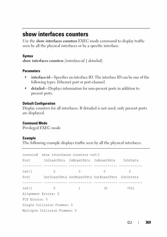
FILE LOCATION: C:\Users\vijaya_devakumar_dev\Documents\PowerConnect\Astute\Docs for Web Posting\Astute_Admin_Guide_sources_MIF7\FM\Dell_Astute_CLI_new.fm
D E L L C O N F I D E N T I A L – P R E L I M I N A RY 3 / 1 9 / 1 5 - F O R P R O O F O N LY
show interfaces countersUse the show interfaces counters EXEC mode command to display traffic seen by all the physical interfaces or by a specific interface.
Syntaxshow interfaces counters [interface-id | detailed]
Parameters
• interface-id—Specifies an interface ID. The interface ID can be one of the following types: Ethernet port or port-channel.
• detailed—Displays information for non-present ports in addition to present ports.
Default ConfigurationDisplay counters for all interfaces. If detailed is not used, only present ports are displayed.
Command ModePrivileged EXEC mode
Example The following example displays traffic seen by all the physical interfaces.
console# show interfaces counters te0/1
Port InUcastPkts InMcastPkts InBcastPkts InOctets
---------- ------------ ------------ ------------ ------------
te0/1 0 0 0 0
Port OutUcastPkts OutMcastPkts OutBcastPkts OutOctets
---------- ------------ ------------ ------------ ------------
te0/1 0 1 35 7051
Alignment Errors: 0
FCS Errors: 0
Single Collision Frames: 0
Multiple Collision Frames: 0
CLI 369

3
FILE LOCATION: C:\Users\vijaya_devakumar_dev\Documents\PowerConnect\Astute\Docs for Web Posting\Astute_Admin_Guide_sources_MIF7\FM\Dell_Astute_CLI_new.fm
D E L L C O N F I D E N T I A L – P R E L I M I N A R Y 3 / 1 9 / 1 5 - F O R P R O O F O N LY
SQE Test Errors: 0
Deferred Transmissions: 0
Late Collisions: 0
Excessive Collisions: 0
Carrier Sense Errors: 0
Oversize Packets: 0
Internal MAC Rx Errors: 0
Symbol Errors: 0
Received Pause Frames: 0
Transmitted Pause Frames: 0
The following table describes the fields shown in the display.
Field Description
InOctets Number of received octets.
InUcastPkts Number of received Unicast packets.
InMcastPkts Number of received Unicast packets.
InBcastPkts Number of received broadcast packets.
OutOctets Number of transmitted octets.
OutUcastPkts Number of transmitted Unicast packets.
OutMcastPkts Number of transmitted Unicast packets.
OutBcastPkts Number of transmitted Broadcast packets.
FCS Errors Number of frames received that are an integral number of octets in length but do not pass the FCS check.
Single Collision Frames Number of frames that are involved in a single collision, and are subsequently transmitted successfully.
Multiple Collision Frames Number of frames that are involved in more than one collision and are subsequently transmitted successfully.
70 CLI

FILE LOCATION: C:\Users\vijaya_devakumar_dev\Documents\PowerConnect\Astute\Docs for Web Posting\Astute_Admin_Guide_sources_MIF7\FM\Dell_Astute_CLI_new.fm
D E L L C O N F I D E N T I A L – P R E L I M I N A RY 3 / 1 9 / 1 5 - F O R P R O O F O N LY
show interfaces statusUse the show interfaces status Privileged EXEC mode command to display the status of all interfaces or of a specific interface.
Syntaxshow interfaces status [interface-id | detailed]
Parameters
• interface-id—Specifies an interface ID. The interface ID can be one of the following types: Ethernet port or port-channel.
SQE Test Errors Number of times that the SQE TEST ERROR is received. The SQE TEST ERROR is set in accordance with the rules for verification of the SQE detection mechanism in the PLS Carrier Sense Function as described in IEEE Std. 802.3, 2000 Edition, section 7.2.4.6.
Deferred Transmissions Number of frames for which the first transmission attempt is delayed because the medium is busy.
Late Collisions Number of times that a collision is detected later than one slotTime into the transmission of a packet.
Excessive Collisions Number of frames for which transmission fails due to excessive collisions.
Oversize Packets Number of frames received that exceed the maximum permitted frame size.
Internal MAC Rx Errors Number of frames for which reception fails due to an internal MAC sublayer receive error.
Received Pause Frames Number of MAC Control frames received with an opcode indicating the PAUSE operation.
Transmitted Pause Frames Number of MAC Control frames transmitted on this interface with an opcode indicating the PAUSE operation.
Field Description
CLI 371

3
FILE LOCATION: C:\Users\vijaya_devakumar_dev\Documents\PowerConnect\Astute\Docs for Web Posting\Astute_Admin_Guide_sources_MIF7\FM\Dell_Astute_CLI_new.fm
D E L L C O N F I D E N T I A L – P R E L I M I N A R Y 3 / 1 9 / 1 5 - F O R P R O O F O N LY
• detailed—Displays information for non-present ports in addition to present ports.
Command ModePrivileged EXEC mode
Default ConfigurationDisplay for all interfaces. If detailed is not used, only present ports are displayed.
ExampleThe following example displays the status of all configured interfaces.
console# show interfaces status
Flow Link Back Mdix
Port Type Duplex Speed Neg ctrl State Pressure Mode
------ --------- ------ ----- -------- ---- ------ -------- --
te0/1 1G-Copper Full 1000 Disabled Off Up Disabled Off
te0/2 1G-Copper -- -- -- -- Down -- --
Flow Link
PO Type Duplex Speed Neg control State
----- ------- ------ ----- ------- ---- ------
Po1 1G Full 10000 Disabled Off Up
show ip dhcp tftp-serverUse the show ip dhcp tftp-server EXEC mode command to display information about the backup server.
Syntaxshow ip dhcp tftp-server
ParametersN/A
72 CLI

FILE LOCATION: C:\Users\vijaya_devakumar_dev\Documents\PowerConnect\Astute\Docs for Web Posting\Astute_Admin_Guide_sources_MIF7\FM\Dell_Astute_CLI_new.fm
D E L L C O N F I D E N T I A L – P R E L I M I N A RY 3 / 1 9 / 1 5 - F O R P R O O F O N LY
Default ConfigurationN/A
Command Mode User EXEC mode
User GuidelinesThe backup server can be a TFTP server.
Example
show ip dhcp tftp-server
tftp server address
active 1.1.1.1 from sname
file path on tftp server
active conf/conf-file from option 67
show ip httpsThe show ip https EXEC mode command displays the HTTPS server configuration.
Syntaxshow ip https
Command ModePrivileged EXEC mode
ExampleThe following example displays the HTTPS server configuration.
console# show ip https
HTTPS server enabled
Port: 443
Interactive timeout: Follows the HTTP interactive timeout (10 minutes)
CLI 373

3
FILE LOCATION: C:\Users\vijaya_devakumar_dev\Documents\PowerConnect\Astute\Docs for Web Posting\Astute_Admin_Guide_sources_MIF7\FM\Dell_Astute_CLI_new.fm
D E L L C O N F I D E N T I A L – P R E L I M I N A R Y 3 / 1 9 / 1 5 - F O R P R O O F O N LY
Certificate 1 is active
Issued by: www.verisign.com
Valid from: 8/9/2003 to 8/9/2004
Subject: CN= router.gm.com, 0= General Motors, C= US
Finger print: DC789788 DC88A988 127897BC BB789788
Certificate 2 is inactive
Issued by: self-signed
Valid from: 8/9/2003 to 8/9/2004
Subject: CN= router.gm.com, 0= General Motors, C= US
Finger print: 1873B936 88DC3411 BC8932EF 782134BA
show ip interfaceUse the show ip interface EXEC mode command to display the usability status of configured IP interfaces.
Syntaxshow ip interface [interface-id]
Parameters
• interface-id—Specifies an interface ID on which IP addresses are defined.
Default ConfigurationAll IP addresses.
Command ModeUser EXEC mode
Examples
Example 1 - The following example displays all configured IP addresses and their types:
74 CLI

FILE LOCATION: C:\Users\vijaya_devakumar_dev\Documents\PowerConnect\Astute\Docs for Web Posting\Astute_Admin_Guide_sources_MIF7\FM\Dell_Astute_CLI_new.fm
D E L L C O N F I D E N T I A L – P R E L I M I N A RY 3 / 1 9 / 1 5 - F O R P R O O F O N LY
console# show ip interface
!source_precedence_is_supported && !broadcast_address_configuration_is_supported && !ip_redirects_is_supported
IP Address I/F I/F Status Type Directed Status
admin/oper Broadcast
------------- ------ ----------- ------- -------- -----
10.5.230.232/24 vlan 1 UP/UP Static disable Valid
10.5.234.202/24 vlan 4 UP/DOWN Static disable Valid
Example 2 - The following example displays the IP addresses configured on the given L2 interfaces and their types:
console# show ip interface vlan 1
!source_precedence_is_supported && !broadcast_address_configuration_is_supported && !ip_redirects_is_supported
IP Address I/F I/F Status Type Directed Status
admin/oper Broadcast
------------- ------ ----------- ------- -------- -----
10.5.230.232/24 vlan 1 UP/UP Static disable Valid
show power inlineUse the show power inline Privileged EXEC mode command to display information about the inline power for all interfaces or for a specific interface.
This command is only supported on devices that support PoE.
Syntaxshow power inline [interface-id | module stack-member-number]
Parameters
• interface-id—Specifies an interface ID. The interface ID must be an Ethernet port.
CLI 375

3
FILE LOCATION: C:\Users\vijaya_devakumar_dev\Documents\PowerConnect\Astute\Docs for Web Posting\Astute_Admin_Guide_sources_MIF7\FM\Dell_Astute_CLI_new.fm
D E L L C O N F I D E N T I A L – P R E L I M I N A R Y 3 / 1 9 / 1 5 - F O R P R O O F O N LY
Default ConfigurationThere is no default configuration for this command.
Command ModeEXEC mode
Example
The following example displays information about the inline power for a specific port.
console(config)# show power inline gi1/1/1
Port Powered Device State Status Priority Class
----- -------------- ------- ------ -------- -------
gi1/1/1 IP Phone Model A Auto On High Class0
Power limit (for port power-limit mode): 15.4W
Overload Counter: 0
Short Counter: 0
Denied Counter: 0
Absent Counter: 0
Invalid Signature Counter: 0
The following table describes the fields shown in the display:
Field Description
Power The inline power sourcing equipment operational status.
Nominal Power The inline power sourcing equipment nominal power in Watts.
Consumed Power The measured usage power in Watts.
Usage Threshold The usage threshold expressed in percent for comparing the measured power and initiating an alarm if threshold is exceeded.
Traps Indicates if inline power traps are enabled.
Port The Ethernet port number.
Powered device A description of the powered device type.
76 CLI

FILE LOCATION: C:\Users\vijaya_devakumar_dev\Documents\PowerConnect\Astute\Docs for Web Posting\Astute_Admin_Guide_sources_MIF7\FM\Dell_Astute_CLI_new.fm
D E L L C O N F I D E N T I A L – P R E L I M I N A RY 3 / 1 9 / 1 5 - F O R P R O O F O N LY
The following table describes the fields shown in the display:
Following is a list of port status values:
Port is on - valid capacitor detected
Port is on - valid resistor detected
Port is off - main supply voltage is high
Port is off - main supply voltage is low
Port is off -‘disable all ports’ pin is active
Port is off - non-existing port number Fewer ports are available than the max.
Port is off - Port is yet undefined
Port is off - internal hardware fault
Port is off - user setting
Port is off - detection is in process
Port is off - non-802.3af powered device
Port is off - Overload & Underload states
Port is off – Underload state
Admin State Indicates if the port is enabled to provide power. The possible values are Auto or Never.
Priority The port inline power management priority. The possible values are Critical, High or Low.
Oper State Describes the port inline power operational state. The possible values are On, Off, Test-Fail, Testing, Searching or Fault.
Classification The power consumption classification of the powered device.
Overload Counter Counts the number of overload conditions detected.
Short Counter Counts the number of short conditions detected.
Denied Counter Counts the number of times power was denied.
Absent Counter Counts the number of times power was removed because powered device dropout was detected.
Invalid Signature Counter
Counts the number of times an invalid signature of a powered device was detected.
Field Descript ion
CLI 377

3
FILE LOCATION: C:\Users\vijaya_devakumar_dev\Documents\PowerConnect\Astute\Docs for Web Posting\Astute_Admin_Guide_sources_MIF7\FM\Dell_Astute_CLI_new.fm
D E L L C O N F I D E N T I A L – P R E L I M I N A R Y 3 / 1 9 / 1 5 - F O R P R O O F O N LY
Port is off – Overload state
Port is off - power budget exceeded
Port is off - internal hardware fault
Port is off – voltage injection into the port
Port is off - improper Capacitor Detection results
Port is off - discharged load Port fails Capacitor
Port is on – detection regardless (Force On)
Undefined error during Force On
Supply voltage higher than settings
Supply voltage lower than settings
Disable_PDU flag raised during Force On
Port is forced on, then disabled
Port is off – forced power error due to Overload
Port is off - “out of power budget” during Force On
Communication error with PoE devices after Force On
Port is off – short condition
Port is off – over temperature at the port
Port is off – device is too hot
Unknown device port status
Force Power Error Short Circuit
Force Power Error Channel Over Temperature
Force Power Error Chip Over Temperature
Power Management-Static
Power Management-Static -ovl
Force Power Error Management Static
Force Power Error Management Static -ovl
High power port is ON
Chip Over Power
Force Power Error Chip Over Power
show power inline consumptionUse the show power inline consumption Privileged EXEC mode command to display information about the inline power consumption for all interfaces or for a specific interface.
This command is only supported on devices that support PoE.
78 CLI

FILE LOCATION: C:\Users\vijaya_devakumar_dev\Documents\PowerConnect\Astute\Docs for Web Posting\Astute_Admin_Guide_sources_MIF7\FM\Dell_Astute_CLI_new.fm
D E L L C O N F I D E N T I A L – P R E L I M I N A RY 3 / 1 9 / 1 5 - F O R P R O O F O N LY
Syntaxshow power inline consumption [interface-id | module stack-member-number]
Parameters
• Interface-id—Specifies an interface ID. The interface ID must be an Ethernet port.
Default ConfigurationThere is no default configuration for this command.
Command ModeEXEC mode
ExampleThe following example displays information about the inline power consumption
.
show running-configUse the show running-config privileged EXEC command to display the contents of the currently running configuration file.
show running-config
ParametersThis command has no arguments or keywords.
Console# show power inline consumption
Port
----
te0/1
te0/1
te0/1
Power Limit (W)
----------
15.4
15.4
15.4
Power (W)
----------
4.115
4.157
4.021
Voltage (V)
---------
50.8
50.7
50.9
Current (mA)
---------
81
82
79
CLI 379
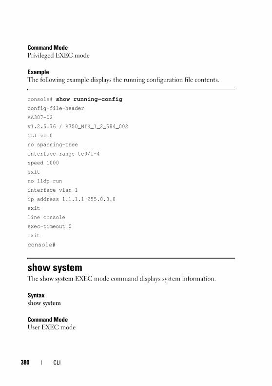
3
FILE LOCATION: C:\Users\vijaya_devakumar_dev\Documents\PowerConnect\Astute\Docs for Web Posting\Astute_Admin_Guide_sources_MIF7\FM\Dell_Astute_CLI_new.fm
D E L L C O N F I D E N T I A L – P R E L I M I N A R Y 3 / 1 9 / 1 5 - F O R P R O O F O N LY
Command ModePrivileged EXEC mode
ExampleThe following example displays the running configuration file contents.
console# show running-config
config-file-header
AA307-02
v1.2.5.76 / R750_NIK_1_2_584_002
CLI v1.0
no spanning-tree
interface range te0/1-4
speed 1000
exit
no lldp run
interface vlan 1
ip address 1.1.1.1 255.0.0.0
exit
line console
exec-timeout 0
exit
console#
show systemThe show system EXEC mode command displays system information.
Syntaxshow system
Command ModeUser EXEC mode
80 CLI

FILE LOCATION: C:\Users\vijaya_devakumar_dev\Documents\PowerConnect\Astute\Docs for Web Posting\Astute_Admin_Guide_sources_MIF7\FM\Dell_Astute_CLI_new.fm
D E L L C O N F I D E N T I A L – P R E L I M I N A RY 3 / 1 9 / 1 5 - F O R P R O O F O N LY
Example
console# show system
System Description:
System Type:
System Up Time (days,hour:min:sec): 03,02:27:46
System Contact:
System Name: switch151400
System Location:
System MAC Address: 00:24:ab:15:14:00
System Object ID: 1.1.3.6
Unit Temperature (Celsius) Status
---- --------------------- ------
1 42 OK
show tech-supportUse the show tech-support Privileged EXEC mode command to display system and configuration information that can be provided to the Technical Assistance Center when reporting a problem.
Syntax show tech-support [config | memory]
Parameters
• memory—Displays memory and processor state data.
• config—Displays switch configuration within the CLI commands supported on the device.
Default Configuration By default, this command displays the output of technical-support-related show commands. Use keywords to specify the type of information to be displayed. If you do not specify any parameters, the system displays all configuration and memory data.
CLI 381

3
FILE LOCATION: C:\Users\vijaya_devakumar_dev\Documents\PowerConnect\Astute\Docs for Web Posting\Astute_Admin_Guide_sources_MIF7\FM\Dell_Astute_CLI_new.fm
D E L L C O N F I D E N T I A L – P R E L I M I N A R Y 3 / 1 9 / 1 5 - F O R P R O O F O N LY
Command Types Switch command.
Command ModeUser EXEC mode
User Guidelines
CAUTION: Avoid running multiple show tech-support commands on a switch or multiple switches on the network segment. Doing so may cause starvation of some time sensitive protocols, such as STP.
The show tech-support command may time out if the configuration file output takes longer to display than the configured session time out time. If this happens, enter a set logout timeout value of 0 to disable automatic disconnection of idle sessions or enter a longer timeout value.
The show tech-support command output is continuous, meaning that it does not display one screen at a time. To interrupt the output, press Esc.
If the user specifies the memory keyword, the show tech-support command displays the following output:
• Flash info (dir if exists, or flash mapping)
• Output of command show bootvar
• Buffers info (like print os buff)
• Memory info (like print os mem)
• Proc info (like print OS tasks)
• Output of command show cpu utilization
show versionThe show version EXEC mode command displays system version information.
Syntaxshow version
82 CLI

FILE LOCATION: C:\Users\vijaya_devakumar_dev\Documents\PowerConnect\Astute\Docs for Web Posting\Astute_Admin_Guide_sources_MIF7\FM\Dell_Astute_CLI_new.fm
D E L L C O N F I D E N T I A L – P R E L I M I N A RY 3 / 1 9 / 1 5 - F O R P R O O F O N LY
Command ModeUser EXEC mode
ExampleThe following example displays system version information.
console# show version
SW Version 1.1.0.5 ( date 15-Sep-2010 time 10:31:33 )
Boot Version 1.1.0.2 ( date 04-Sep-2010 time 21:51:53 )
HW Version A01
show vlanUse the show vlan Privileged EXEC mode command to display the following VLAN information for all VLANs or for a specific VLAN:
• VLAN ID
• VLAN name
• Ports on the VLAN
• Whether the VLAN was is dynamic or permanent
Syntaxshow vlan [tag vlan-id | name vlan-name]
Parameters
• tag vlan-id—Specifies a VLAN ID.
• name vlan-name—Specifies a VLAN name string (length: 1–32 characters)
Default ConfigurationAll VLANs are displayed.
Command ModePrivileged EXEC mode
CLI 383

3
FILE LOCATION: C:\Users\vijaya_devakumar_dev\Documents\PowerConnect\Astute\Docs for Web Posting\Astute_Admin_Guide_sources_MIF7\FM\Dell_Astute_CLI_new.fm
D E L L C O N F I D E N T I A L – P R E L I M I N A R Y 3 / 1 9 / 1 5 - F O R P R O O F O N LY
Examples:Example 1—The following example displays information for all VLANs:
console# show vlan
Created by: D-Default, S-Static, G-GVRP, R-Radius Assigned VLAN
Example 2—The following example displays information for the default VLAN (VLAN 1):
console# show vlan tag 1
Created by: D-Default, S-Static, G-GVRP, R-Radius Assigned VLAN
Example 3—The following example displays information for the VLAN named Marketing:
console# show vlan name Marketing
Created by: D-Default, S-Static, G-GVRP, R-Radius Assigned VLAN
VLAN Name Ports Created by
----- ----------- -------------- ----------
1 Default te0/1 D
10 Marketing te0/2 S
91 11 te0/2 SGR
92 11 te0/3-4 G
93 11 te0/3-4 GR
VLAN Name Ports Created by
----- ----------- -------------- ----------
1 Default te0/1-2 D
VLAN Name Ports Created by
84 CLI

FILE LOCATION: C:\Users\vijaya_devakumar_dev\Documents\PowerConnect\Astute\Docs for Web Posting\Astute_Admin_Guide_sources_MIF7\FM\Dell_Astute_CLI_new.fm
D E L L C O N F I D E N T I A L – P R E L I M I N A RY 3 / 1 9 / 1 5 - F O R P R O O F O N LY
spanning-treeUse the spanning-tree Global Configuration mode command to enable spanning-tree functionality. Use the no form of this command to disable the spanning-tree functionality.
Syntaxspanning-tree
no spanning-tree
ParametersN/A
Default ConfigurationSpanning-tree is enabled.
Command Mode Global Configuration mode
ExampleThe following example enables spanning-tree functionality.
console(config)# spanning-tree
usernameUse the username Global Configuration mode command to establish a username-based authentication system. Use the no form to remove a user name.
Syntaxusername name nopassword | {password {unencrypted-password | {encrypted encrypted-password}}}
----- ----------- -------------- ----------
10 Marketing te0/3-4 S
CLI 385

3
FILE LOCATION: C:\Users\vijaya_devakumar_dev\Documents\PowerConnect\Astute\Docs for Web Posting\Astute_Admin_Guide_sources_MIF7\FM\Dell_Astute_CLI_new.fm
D E L L C O N F I D E N T I A L – P R E L I M I N A R Y 3 / 1 9 / 1 5 - F O R P R O O F O N LY
no username name
Parameters
• name—The name of the user. (Range: 1–20 characters)
• nopassword—No password is required for this user to log in.
• password—Specifies the password for this username. (Range: 1–64)
• unencrypted-password—The authentication password for the user. (Range: 1–159)
• encrypted encrypted-password—Specifies that the password is MD5 encrypted. Use this keyword to enter a password that is already encrypted (for instance that you copied from another the configuration file of another device). (Range: 1–40)
Default ConfigurationNo user is defined.
Command ModeGlobal Configuration mode
Usage GuidelinesThe last user (regardless of whether it is the default user or any user) cannot be removed and cannot be a remote user.
ExampleSets an unencrypted password for user top (level 15). It will be encrypted in the configuration file.
console(config)# username tom password 1234
vlan Use the vlan VLAN Configuration mode or Global Configuration mode command to create a VLAN and assign it a name (if only a single VLAN is being created). Use the no form of this command to delete the VLAN(s).
86 CLI

FILE LOCATION: C:\Users\vijaya_devakumar_dev\Documents\PowerConnect\Astute\Docs for Web Posting\Astute_Admin_Guide_sources_MIF7\FM\Dell_Astute_CLI_new.fm
D E L L C O N F I D E N T I A L – P R E L I M I N A RY 3 / 1 9 / 1 5 - F O R P R O O F O N LY
Syntaxvlan vlan-range | {vlan-id [name vlan-name]}
no vlan vlan-range
Parameters
• vlan-range—Specifies a list of VLAN IDs. Separate nonconsecutive VLAN IDs with a comma and no spaces. Use a hyphen to designate a range of IDs (range: 2-4094).
• vlan-id—Specifies a VLAN ID. (range: 2-4094).
• vlan-name—Specifies the VLAN name. (range: 1–32 characters).
Default ConfigurationVLAN 1 exists by default.
Command ModeGlobal Configuration mode
VLAN Database Configuration mode
User Guidelines If the VLAN does not exist, it is created. If the VLAN cannot be created then the command is finished with error and the current context is not changed.
ExampleThe following example creates VLAN 1972, which is assigned the name Marketing.
console(config)# vlan 1972 name Marketing
console(config)# exit
CLI 387

3
FILE LOCATION: C:\Users\vijaya_devakumar_dev\Documents\PowerConnect\Astute\Docs for Web Posting\Astute_Admin_Guide_sources_MIF7\FM\Dell_Astute_CLI_new.fm
D E L L C O N F I D E N T I A L – P R E L I M I N A R Y 3 / 1 9 / 1 5 - F O R P R O O F O N LY
write Use the write Privileged EXEC mode command to save the running configuration to the startup configuration file.
Syntaxwrite [memory]
ParametersThis command has no arguments or keywords.
Command ModePrivileged EXEC mode
ExamplesThe following example shows how to overwrite the startup-config file with the running-config file with the write command.
console# write
Overwrite file [startup-config] ?[Yes/press any key for no]....15-Sep-2010 11:27
:48 %COPY-I-FILECPY: Files Copy - source URL running-config destination URL flash://startup-config
15-Sep-2010 11:27:50 %COPY-N-TRAP: The copy operation was completed successfully
Copy succeeded
88 CLI
FILE LOCATION: C:\Users\vijaya_devakumar_dev\Documents\PowerConnect\Astute\Docs for Web Posting\Astute_Admin_Guide_sources_MIF7\FM\Dell_Astute_GettingHelp.fm
D E L L C O N F I D E N T I A L – P R E L I M I N A RY 3 / 1 9 / 1 5 - F O R P R O O F O N LY
24Getting Help
Contacting Dell NOTE: Dell provides several online and telephone-based support and service
options. If you do not have an active Internet connection, you can find contact information on your purchase invoice, packing slip, bill, or Dell product catalog. Availability varies by country and product, and some services may not be available in your area.
To contact Dell for sales, technical support, or customer-service issues:
1 Go to dell.com/support.
2 For customized support:
a Enter your system service tag in the Enter your Service Tag field.
b Click Submit.
The support page that lists the various support categories is displayed.
3 For general support:
a Select your product category.
b Select your product segment.
c Select your product.
The support page that lists the various support categories is displayed.
Locating Your System Service TagYour system is identified by a unique Express Service Code and Service Tag number. The Express Service Code and Service Tag are found on the front of the system by pulling out the information tag. Alternatively, the information may be on a sticker on the chassis of the system. This information is used by Dell to route support calls to the appropriate personnel.
Getting Help 389

3
FILE LOCATION: C:\Users\vijaya_devakumar_dev\Documents\PowerConnect\Astute\Docs for Web Posting\Astute_Admin_Guide_sources_MIF7\FM\Dell_Astute_GettingHelp.fm
D E L L C O N F I D E N T I A L – P R E L I M I N A R Y 3 / 1 9 / 1 5 - F O R P R O O F O N LY
Downloading Drivers, Firmware, and Software1 Go to dell.com/support.
2 Enter your system service tag in the Enter your Service Tag field.
3 Click Submit.
The support page that lists the various support categories is displayed.
4 From the left pane, select Get drivers and downloads.
5 Select your filters.
6 View by Category, Importance, or Release Date.
Related Documentation WARNING: See the safety and regulatory information that shipped with your
system. Warranty information may be included within this document or as a separate document.
NOTE: Ensure that all the component software are upgraded to the latest versions.
NOTE: Always check for updates on dell.com/support/manuals and read the updates first because they often supersede information in other documents.
Any media that ships with your system provides documentation and tools for configuring and managing your system, including those pertaining to the operating system, system management software, system updates, and system components that you purchased with your system.
The following guides are provided:
• Dell™ Networking™ X1000 and X4000 Series Switches Getting Started Guide shipped with your system provides an overview of product features, setting up your product, and technical specifications.
These documents are available online at dell.com/support/my-support/us/en/19/product-support/product/poweredge-vrtx/manuals.
Documentation FeedbackIf you have feedback for this document, write to [email protected]. Alternatively, you can click on the Feedback link in any of the Dell documentation pages, fill out the form, and click Submit to send your feedback.
90 Getting Help
FILE LOCATION: C:\Users\vijaya_devakumar_dev\Documents\PowerConnect\Astute\Docs for Web Posting\Astute_Admin_Guide_sources_MIF7\FM\Dell_Astute_Glossary.fm
D E L L C O N F I D E N T I A L – P R E L I M I N A RY 3 / 1 9 / 1 5 - F O R P R O O F O N LY
GlossaryFigure 25-1. This glossary contains key technical words of interest.
A
Access Mode
Specifies the method by which user access is granted to the system.
Access Profiles
Allows network managers to define profiles and rules for accessing the switch module. Access to management functions can be limited to user groups, which are defined by the following criteria:
• Ingress interfaces
• Source IP address or Source IP subnets
ACL
Access Control List. Allow network managers to define classification actions and rules for specific ingress ports.
Aggregated VLAN
Groups several VLANs into a single aggregated VLAN. Aggregating VLANs enables routers to respond to ARP requests for nodes located on different sub-VLANs belonging to the same Super VLAN. Routers respond with their MAC address.
ARP
Address Resolution Protocol. A protocol that converts IP addresses into physical addresses.
ASIC
Application Specific Integrated Circuit. A custom chip designed for a specific application.
Asset Tag
Specifies the user-defined switch module reference.
A B C D E F G H I L M N O P Q
R S T U V W
391

3
FILE LOCATION: C:\Users\vijaya_devakumar_dev\Documents\PowerConnect\Astute\Docs for Web Posting\Astute_Admin_Guide_sources_MIF7\FM\Dell_Astute_Glossary.fm
D E L L C O N F I D E N T I A L – P R E L I M I N A R Y 3 / 1 9 / 1 5 - F O R P R O O F O N LY
Authentication Profiles
Sets of rules which that enables login to and authentication of users and applications.
Auto-negotiation
Allows 10/100 Mpbs or 10/100/1000 Mbps Ethernet ports to establish for the following features:
• Duplex/Half Duplex mode
• Flow Control
• Speed
B
Back Pressure
A mechanism used with Half Duplex mode that enables a port not to receive a message.
Backplane
The main BUS that carries information in the switch module.
Backup Configuration Files
Contains a backup copy of the switch module configuration. The Backup file changes when the Running Configuration file or the Startup Configuration file is copied to the Backup file.
Bandwidth
Bandwidth specifies the amount of data that can be transmitted in a fixed amount of time. For digital switch modules, bandwidth is defined in Bits per Second (bps) or Bytes per Second.
Bandwidth Assignments
The amount of bandwidth assigned to a specific application, user, or interface.
Baud
The number of signaling elements transmitted each second.
Best Effort
Traffic is assigned to the lowest priority queue, and packet delivery is not guaranteed.
92

FILE LOCATION: C:\Users\vijaya_devakumar_dev\Documents\PowerConnect\Astute\Docs for Web Posting\Astute_Admin_Guide_sources_MIF7\FM\Dell_Astute_Glossary.fm
D E L L C O N F I D E N T I A L – P R E L I M I N A RY 3 / 1 9 / 1 5 - F O R P R O O F O N LY
Boot Version
The boot version.
BootP
Bootstrap Protocol. Enables a workstation to discover its IP address, an IP address of a BootP server on a network, or a configuration file loaded into the boot of a switch module.
BPDU
Bridge Protocol Data Unit. Provide bridging information in a message format. BPDUs are sent across switch module information with in Spanning Tree configuration. BPDU packets contain information on ports, addresses, priorities, and forwarding costs.
Bridge
A device that connect two networks. Bridges are hardware specific, however they are protocol independent. Bridges operate at Layer 1 and Layer 2 levels.
Broadcast Domain
Device sets that receive Broadcast frames originating from any device within a designated set. Routers bind Broadcast domains, because routers do not forward Broadcast frames.
Broadcasting
A method of transmitting packets to all ports on a network.
Broadcast Storm
An excessive amount of Broadcast messages simultaneously transmitted across a network by a single port. Forwarded message responses are heaped onto the network, overloading network resources or causing the network to time out.
C
CDB
Configuration Data Base. A file containing a device’s configuration information.
Class of Service
393

3
FILE LOCATION: C:\Users\vijaya_devakumar_dev\Documents\PowerConnect\Astute\Docs for Web Posting\Astute_Admin_Guide_sources_MIF7\FM\Dell_Astute_Glossary.fm
D E L L C O N F I D E N T I A L – P R E L I M I N A R Y 3 / 1 9 / 1 5 - F O R P R O O F O N LY
Class of Service (CoS). Class of Service is the 802.1p priority scheme. CoS provides a method for tagging packets with priority information. A CoS value between 0-7 is added to the Layer II header of packets, where zero is the lowest priority and seven is the highest.
A overlapping transmission of two or more packets that collide. The data transmitted cannot be used, and the session is restarted.
CLI
Command Line Interface. A set of line commands used to configure the system.
Communities
Specifies a group of users which retains the same system access rights.
CPU
Central Processing Unit. The part of a computer that processes information. CPUs are composed of a control unit and an ALU.
D
DHCP Client
A device using DHCP to obtain configuration parameters, such as a network address.
DHCP Snooping
DHCP Snooping expands network security by providing firewall security between untrusted interfaces and DHCP servers.
DSCP
DiffServe Code Point (DSCP). DSCP provides a method of tagging IP packets with QoS priority information.
Domain
A group of computers and devices on a network that are grouped with common rules and procedures.
Duplex Mode
Permits simultaneous transmissions and reception of data. There are two different types of duplex mode:
94

FILE LOCATION: C:\Users\vijaya_devakumar_dev\Documents\PowerConnect\Astute\Docs for Web Posting\Astute_Admin_Guide_sources_MIF7\FM\Dell_Astute_Glossary.fm
D E L L C O N F I D E N T I A L – P R E L I M I N A RY 3 / 1 9 / 1 5 - F O R P R O O F O N LY
• Full Duplex Mode — Permits for bisynchronous communication, for example, a telephone. Two parties can transmit information at the same time.
• Half Duplex Mode — Permits asynchronous communication, for example, a walkie-talkie. Only one party can transmit information at a time.
Dynamic VLAN Assignment (DVA)
Allows automatic assignment of users to VLANs during the RADIUS server authentication. When a user is authenticated by the RADIUS server, the user is automatically joined to the VLAN configured on the RADIUS server.
E
Egress Ports
Ports from which network traffic is transmitted.
End System
An end user device on a network.
Ethernet
Ethernet is standardized as per IEEE 802.3. Ethernet is the most common implemented LAN standard. Supports data transfer rates of Mpbs, where 10, 100 or 1000 Mbps is supported.
EWS
Embedded Web Server. Provides device management via a standard web browser. Embedded Web Servers are used in addition to or in place of a CLI or NMS.
F
FFT
Fast Forward Table. Provides information about forwarding routes. If a packet arrives to a device with a known route, the packet is forwarded via a route listed in the FFT. If there is not a known route, the CPU forwards the packet and updates the FFT.
FIFO
First In First Out. A queuing process where the first packet in the queue is the first packet out of the packet.
395

3
FILE LOCATION: C:\Users\vijaya_devakumar_dev\Documents\PowerConnect\Astute\Docs for Web Posting\Astute_Admin_Guide_sources_MIF7\FM\Dell_Astute_Glossary.fm
D E L L C O N F I D E N T I A L – P R E L I M I N A R Y 3 / 1 9 / 1 5 - F O R P R O O F O N LY
Flapping
Flapping occurs when an interfaces state is constantly changing. For example, an STP port constantly changes from listening to learning to forwarding. This may cause traffic loss.
Flow Control
Enables lower speed devices to communicate with higher speed devices, that is, that the higher speed device refrains from sending packets.
Fragment
Ethernet packets smaller than 576 bits.
Frame
Packets containing the header and trailer information required by the physical medium.
G
GARP
General Attributes Registration Protocol. Registers client stations into a Multicast domain.
Gigabit Ethernet
Gigabit Ethernet transmits at 1000 Mbps, and is compatible with existing 10/100 Mbps Ethernet standards.
GVRP
GARP VLAN Registration Protocol. Registers client stations into a VLANs.
H
HOL
Head of Line. Packets are queued. Packets at the head of the queue are forwarded before packets at the end of the line.
Host
A computer that acts as a source of information or services to other computers.
HTTP
96

FILE LOCATION: C:\Users\vijaya_devakumar_dev\Documents\PowerConnect\Astute\Docs for Web Posting\Astute_Admin_Guide_sources_MIF7\FM\Dell_Astute_Glossary.fm
D E L L C O N F I D E N T I A L – P R E L I M I N A RY 3 / 1 9 / 1 5 - F O R P R O O F O N LY
HyperText Transport Protocol. Transmits HTML documents between servers and clients on the internet.
I
IC
Integrated Circuit. Integrated Circuits are small electronic devices composed from semiconductor material.
ICMP
Internet Control Message Protocol. Allows gateway or destination host to communicate with a source host, for example, to report a processing error.
IEEE
Institute of Electrical and Electronics Engineers. An Engineering organization that develops communications and networking standards.
IEEE 802.1d
Used in the Spanning Tree Protocol, IEEE 802.1d supports MAC bridging to avoid network loops.
IEEE 802.1p
Prioritizes network traffic at the data-link/MAC sublayer.
IEEE 802.1Q
Defines the operation of VLAN Bridges that permit the definition, operation, and administration of VLANs within Bridged LAN infrastructures.
IGMP Snooping
IGMP Snooping examines IGMP frame contents, when they are forwarded by the device from work stations to an upstream Multicast router. From the frame, the device identifies work stations configured for Multicast sessions, and which Multicast routers are sending Multicast frames.
Image File
System images are saved in two Flash sectors called images (Image 1 and Image 2). The active image stores the active copy; while the other image stores a second copy.
Ingress Port
Ports on which network traffic is received.
397

3
FILE LOCATION: C:\Users\vijaya_devakumar_dev\Documents\PowerConnect\Astute\Docs for Web Posting\Astute_Admin_Guide_sources_MIF7\FM\Dell_Astute_Glossary.fm
D E L L C O N F I D E N T I A L – P R E L I M I N A R Y 3 / 1 9 / 1 5 - F O R P R O O F O N LY
IP
Internet Protocol. Specifies the format of packets and there addressing method. IP addresses packets and forwards the packets to the correct port.
IP Address
Internet Protocol Address. A unique address assigned to a network device with two or more interconnected LANs or WANs.
IP Version 6 (IPv6)
A version of IP addressing with longer addresses than the traditional IPv4. IPv6 addresses are 128 bits long, whereas IPv4 addresses are 32 bits; allowing a much larger address space.
ISATAP
Intra-Site Automatic Tunnel Addressing Protocol .l.ISATAP is an automatic overlay tunneling mechanism that uses the underlying IPv4 network as a non-Broadcast/multicast access link layer for IPv6. ISATAP is designed for transporting IPv6 packets within a site where a native IPv6 infrastructure is not yet available.
L
LAG
Link Aggregated Group. Aggregates ports or VLANs into a single virtual port or VLAN.
For more information on LAGs, see Defining LAG Membership.
LAN
Local Area Networks. A network contained within a single room, building, campus or other limited geographical area.
LACP
Link Aggregation Control Protocol (LACP). LACP is part of the IEEE specification 802.3ad that enables bundling several physical ports to form a single logical channel.
Layer 2
Data Link Layer or MAC Layer. Contains the physical address of a client or server station. Layer 2 processing is faster than Layer 3 processing because there is less information to process.
98

FILE LOCATION: C:\Users\vijaya_devakumar_dev\Documents\PowerConnect\Astute\Docs for Web Posting\Astute_Admin_Guide_sources_MIF7\FM\Dell_Astute_Glossary.fm
D E L L C O N F I D E N T I A L – P R E L I M I N A RY 3 / 1 9 / 1 5 - F O R P R O O F O N LY
Layer 3
Establishes a connections and ensures that all data arrives to their destination. Packets inspected at the Layer 3 level are analyzed and forwarding decisions, based on their applications.
LLDP-MED
Link Layer Discovery Protocol - Media Endpoint Discovery. LLDP allows network managers to troubleshoot and enhance network management by discovering and maintaining network topologies over multi-vendor environments. MED increases network flexibility by allowing different IP systems to co-exist on a single network LLDP.
Load Balancing
Enables the even distribution of data or processing packets across available network resources. For example, load balancing may distribute the incoming packets evenly to all servers, or redirect the packets to the next available server.
M
MAC Address
Media Access Control Address. The MAC Address is a hardware specific address that identifies each network node.
MAC Address Learning
MAC Address Learning characterizes a learning bridge, in which the packet’s source MAC address is recorded. Packets destined for that address are forwarded only to the bridge interface on which that address is located. Packets addressed to unknown addresses are forwarded to every bridge interface. MAC Address Learning minimizes traffic on the attached LANs.
MAC Layer
A sub-layer of the Data Link Control (DTL) layer.
Mask
A filter that includes or excludes certain values, for example parts of an IP address.
MD5
399
4
FILE LOCATION: C:\Users\vijaya_devakumar_dev\Documents\PowerConnect\Astute\Docs for Web Posting\Astute_Admin_Guide_sources_MIF7\FM\Dell_Astute_Glossary.fm
D E L L C O N F I D E N T I A L – P R E L I M I N A R Y 3 / 1 9 / 1 5 - F O R P R O O F O N LY
Message Digest 5. An algorithm that produces a 128-bit hash. MD5 is a variation of MD4, and increases MD4 security. MD5 verifies the integrity of the communication, authenticates the origin of the communication.
MDI
Media Dependent Interface. A cable used for end stations.
MDIX
Media Dependent Interface with Crossover (MDIX). A cable used for hubs and switches.
MIB
Management Information Base. MIBs contain information describing specific aspects of network components.
Multicast
Transmits copies of a single packet to multiple ports.
Multicast TV VLAN
Multicast Television Vlan or TV VLAN, is used for television applications with a PC or with televisions equipped with a "Set-Top Box" device.
N
NA
Neighbor Advertisement.
ND
Neighbor Discovery.
NS
Neighbor Solicitation.
NMS
Network Management System. An interface that provides a method of managing a system.
Node
A network connection endpoint or a common junction for multiple network lines. Nodes include:
• Processors
00

FILE LOCATION: C:\Users\vijaya_devakumar_dev\Documents\PowerConnect\Astute\Docs for Web Posting\Astute_Admin_Guide_sources_MIF7\FM\Dell_Astute_Glossary.fm
D E L L C O N F I D E N T I A L – P R E L I M I N A RY 3 / 1 9 / 1 5 - F O R P R O O F O N LY
• Controllers
• Workstations
O
OID
Organizationally Unique Identifiers. Identifiers associated with a Voice VLAN.
OUI
Object Identifier. Used by SNMP to identify managed objects. In the SNMP Manager/Agent network management paradigm, each managed object must have an OID to identify it.
P
Packets
Blocks of information for transmission in packet switched systems.
PDU
Protocol Data Unit. A data unit specified in a layer protocol consisting of protocol control information and layer user data.
PING
Packet Internet Groper. Verifies if a specific IP address is available. A packet is sent to another IP address and waits for a reply.
Port
Physical ports provide connecting components that allow microprocessors to communicate with peripheral equipment.
Port Mirroring
Monitors and mirrors network traffic by forwarding copies of incoming and outgoing packets from one port to a monitoring port.
Protocol
A set of rules that governs how devices exchange information across networks.
PVE
Protocol VLAN Edge. A port can be defined as a Private VLAN Edge (PVE) port of an uplink port, so that it will be isolated from other ports within the same VLAN.
401

4
FILE LOCATION: C:\Users\vijaya_devakumar_dev\Documents\PowerConnect\Astute\Docs for Web Posting\Astute_Admin_Guide_sources_MIF7\FM\Dell_Astute_Glossary.fm
D E L L C O N F I D E N T I A L – P R E L I M I N A R Y 3 / 1 9 / 1 5 - F O R P R O O F O N LY
Q
QoS
Quality of Service. QoS allows network managers to decide how and what network traffic is forwarded according to priorities, application types, and source and destination addresses.
Query
Extracts information from a database and presents the information for use.
R
RA
RADIUS Advertisement.
RD
RADIUS Discovery.
RS
Router Solicitation.
RADIUS
Remote Authentication Dial-In User Service. A method for authenticating system users, and tracking connection time.
RMON
Remote Monitoring. Provides network information to be collected from a single workstation.
Router
A device that connects to separate networks. Routers forward packets between two or more networks. Routers operate at a Layer 3 level.
RSTP
Rapid Spanning Tree Protocol. Detects and uses network topologies that allow a faster convergence of the spanning tree, without creating forwarding loops.
Running Configuration File
Contains all startup configuration file commands, as well as all commands entered during the current session. After the switch module is powered down or rebooted, all commands stored in the Running Configuration file are lost.
02

FILE LOCATION: C:\Users\vijaya_devakumar_dev\Documents\PowerConnect\Astute\Docs for Web Posting\Astute_Admin_Guide_sources_MIF7\FM\Dell_Astute_Glossary.fm
D E L L C O N F I D E N T I A L – P R E L I M I N A RY 3 / 1 9 / 1 5 - F O R P R O O F O N LY
S
Segmentation
Divides LANs into separate LAN segments for bridging. Segmentation eliminates LAN bandwidth limitations.
Server
A central computer that provides services to other computers on a network. Services may include file storage and access to applications.
SNMP
Simple Network Management Protocol. Manages LANs. SNMP based software communicates with network devices with embedded SNMP agents. SNMP agents gather network activity and device status information, and send the information back to a workstation.
SNTP
Simple Network Time Protocol. SNTP assures accurate network switch clock time synchronization up to the millisecond.
SoC
System on a Chip. An ASIC that contains an entire system. For example, a telecom SoC application can contain a microprocessor, digital signal processor, RAM, and ROM.
Spanning Tree Protocol
Prevents loops in network traffic. The Spanning Tree Protocol (STP) provides tree topography for any arrangement of bridges. STP provides one path between end stations on a network, eliminating loops.
SSH
Secure Shell. Permits logging to another computer over a network, execute commands on a remote machine, and move files from one machine to another. Secure Shell provides strong authentication and secure communications methods over insecure channels.
Startup Configuration
Retains the exact switch module configuration when the switch module is powered down or rebooted.
Subnet
403

4
FILE LOCATION: C:\Users\vijaya_devakumar_dev\Documents\PowerConnect\Astute\Docs for Web Posting\Astute_Admin_Guide_sources_MIF7\FM\Dell_Astute_Glossary.fm
D E L L C O N F I D E N T I A L – P R E L I M I N A R Y 3 / 1 9 / 1 5 - F O R P R O O F O N LY
Sub-network. Subnets are portions of a network that share a common address component. On TCP/IP networks, devices that share a prefix are part of the same subnet. For example, all devices with a prefix of 157.100.100.100 are part of the same subnet.
Subnet Mask
Used to mask all or part of an IP address used in a subnet address.
Switch
Filters and forwards packets between LAN segments. Switches support any packet protocol type.
T
TCP/IP
Transmissions Control Protocol. Enables two hosts to communicate and exchange data streams. TCP guarantees packet delivery, and guarantees packets are transmitted and received in the order their sent.
TCP/IP Congestion Avoidance
Transmissions Control Protocol Congestion Avoidance. The TCP Congestion Avoidance feature activates an algorithm that breaks up or prevents TCP global synchronization on a congested node, where the congestion is due to multiple sources sending packets with the same byte count.
Telnet
Terminal Emulation Protocol. Enables system users to log in and use resources on remote networks.
TFTP
Trivial File Transfer Protocol. Uses User Data Protocol (UDP) without security features to transfer files.
Trap
A message sent by the SNMP that indicates that system event has occurred.
Trunking
Link Aggregation. Optimizes port usage by linking a group of ports together to form a single trunk (aggregated groups).
TV VLAN
04

FILE LOCATION: C:\Users\vijaya_devakumar_dev\Documents\PowerConnect\Astute\Docs for Web Posting\Astute_Admin_Guide_sources_MIF7\FM\Dell_Astute_Glossary.fm
D E L L C O N F I D E N T I A L – P R E L I M I N A RY 3 / 1 9 / 1 5 - F O R P R O O F O N LY
Multicast Television Vlan or TV VLAN, is used for television applications with a PC or with televisions equipped with a "Set-Top Box" device.
U
UDP
User Data Protocol. Transmits packets but does not guarantee their delivery.
Unicast
A form of routing that transmits one packet to one user.
V
VLAN
Virtual Local Area Networks. Logical subgroups with a Local Area Network (LAN) created via software rather than defining a hardware solution.
VoIP
Voice over IP.
W
WAN
Wide Area Networks. Networks that cover a large geographical area.
Wildcard Mask
Specifies which IP address bits are used, and which bits are ignored. A wild switch module mask of 255.255.255.255 indicates that no bit is important. A wildcard of 0.0.0.0 indicates that all the bits are important.
405

4
FILE LOCATION: C:\Users\vijaya_devakumar_dev\Documents\PowerConnect\Astute\Docs for Web Posting\Astute_Admin_Guide_sources_MIF7\FM\Dell_Astute_Glossary.fm
D E L L C O N F I D E N T I A L – P R E L I M I N A R Y 3 / 1 9 / 1 5 - F O R P R O O F O N LY
06