Embed Size (px)
Citation preview

Dell OptiPlex 9010/7010 Small Form FactorOwner's Manual
Regulatory Model: D03SRegulatory Type: D03S002

Notes, cautions, and warningsNOTE: A NOTE indicates important information that helps you make better use of your computer.
CAUTION: A CAUTION indicates either potential damage to hardware or loss of data and tells you how to avoid the problem.
WARNING: A WARNING indicates a potential for property damage, personal injury, or death.
Copyright © 2015 Dell Inc. All rights reserved. This product is protected by U.S. and international copyright and intellectual property laws. Dell™ and the Dell logo are trademarks of Dell Inc. in the United States and/or other jurisdictions. All other marks and names mentioned herein may be trademarks of their respective companies.
2015 – 05
Rev. A02
Contents
1 Working on Your Computer....................................................................................................... 5Before Working Inside Your Computer.....................................................................................................................5Turning Off Your Computer....................................................................................................................................... 6After Working Inside Your Computer........................................................................................................................6
2 Removing and Installing Components..................................................................................... 8Recommended Tools................................................................................................................................................ 8Removing the Cover..................................................................................................................................................8Installing the Cover................................................................................................................................................... 8Removing the Front Bezel......................................................................................................................................... 9Installing the Front Bezel........................................................................................................................................ 10Removing The Wireless Local Area Network (WLAN) Card.................................................................................. 10Installing The WLAN Card...................................................................................................................................... 11Removing the Drive Cage....................................................................................................................................... 11Installing the Drive Cage.........................................................................................................................................13Removing the Optical Drive.................................................................................................................................... 13Installing the Optical Drive..................................................................................................................................... 15Removing the Hard Drive........................................................................................................................................ 15Installing the Hard Drive......................................................................................................................................... 16Removing the Intrusion Switch...............................................................................................................................17Installing the Intrusion Switch................................................................................................................................18Removing The Expansion Card............................................................................................................................... 18Installing The Expansion Card................................................................................................................................ 19Memory Module Guidelines................................................................................................................................... 20Removing the Memory............................................................................................................................................20Installing the Memory.............................................................................................................................................21Removing the Coin-Cell Battery..............................................................................................................................21Installing the Coin-Cell Battery...............................................................................................................................22Removing the System Fan.......................................................................................................................................22Installing the System Fan........................................................................................................................................24Removing the Speaker............................................................................................................................................24Installing the Speaker.............................................................................................................................................25Removing the Power-Switch Cable........................................................................................................................ 25Installing the Power-Switch Cable......................................................................................................................... 26Removing the Input/Output (I/O) Panel................................................................................................................... 26Installing the Input/Output (I/O) Panel.................................................................................................................... 27Removing the Power Supply...................................................................................................................................28Installing the Power Supply....................................................................................................................................31
3
Removing the Heat Sink .........................................................................................................................................31Installing the Heat Sink...........................................................................................................................................34Removing the Processor.........................................................................................................................................34Installing the Processor..........................................................................................................................................35Removing the System Board...................................................................................................................................35System Board Components.................................................................................................................................... 38Installing the System Board....................................................................................................................................38
3 System Setup............................................................................................................................. 40Boot Sequence....................................................................................................................................................... 40Navigation Keys......................................................................................................................................................40System Setup Options.............................................................................................................................................41Updating the BIOS ................................................................................................................................................. 49Jumper Settings......................................................................................................................................................49System and Setup Password..................................................................................................................................50
Assigning a System Password and Setup Password...................................................................................... 50Deleting or Changing an Existing System and/or Setup Password..................................................................51Disabling a System Password..........................................................................................................................51
4 Diagnostics.................................................................................................................................52Enhanced Pre-Boot System Assessment (ePSA) Diagnostics...............................................................................52
5 Troubleshooting Your Computer.............................................................................................53Power LED Diagnostics.......................................................................................................................................... 53Beep Code.............................................................................................................................................................. 54Error Messages...................................................................................................................................................... 54
6 Specifications............................................................................................................................ 58
7 Contacting Dell ......................................................................................................................... 65
4
1Working on Your Computer
Before Working Inside Your ComputerUse the following safety guidelines to help protect your computer from potential damage and to help to ensure your personal safety. Unless otherwise noted, each procedure included in this document assumes that the following conditions exist:
• You have read the safety information that shipped with your computer.
• A component can be replaced or--if purchased separately--installed by performing the removal procedure in reverse order.
WARNING: Disconnect all power sources before opening the computer cover or panels. After you finish working inside the computer, replace all covers, panels, and screws before connecting to the power source.
WARNING: Before working inside your computer, read the safety information that shipped with your computer. For additional safety best practices information, see the Regulatory Compliance Homepage at www.dell.com/regulatory_compliance
CAUTION: Many repairs may only be done by a certified service technician. You should only perform troubleshooting and simple repairs as authorized in your product documentation, or as directed by the online or telephone service and support team. Damage due to servicing that is not authorized by Dell is not covered by your warranty. Read and follow the safety instructions that came with the product.
CAUTION: To avoid electrostatic discharge, ground yourself by using a wrist grounding strap or by periodically touching an unpainted metal surface, such as a connector on the back of the computer.
CAUTION: Handle components and cards with care. Do not touch the components or contacts on a card. Hold a card by its edges or by its metal mounting bracket. Hold a component such as a processor by its edges, not by its pins.
CAUTION: When you disconnect a cable, pull on its connector or on its pull-tab, not on the cable itself. Some cables have connectors with locking tabs; if you are disconnecting this type of cable, press in on the locking tabs before you disconnect the cable. As you pull connectors apart, keep them evenly aligned to avoid bending any connector pins. Also, before you connect a cable, ensure that both connectors are correctly oriented and aligned.
NOTE: The color of your computer and certain components may appear differently than shown in this document.
To avoid damaging your computer, perform the following steps before you begin working inside the computer.
1. Ensure that your work surface is flat and clean to prevent the computer cover from being scratched.2. Turn off your computer (see Turning Off Your Computer).
CAUTION: To disconnect a network cable, first unplug the cable from your computer and then unplug the cable from the network device.
3. Disconnect all network cables from the computer.4. Disconnect your computer and all attached devices from their electrical outlets.
5
5. Press and hold the power button while the computer is unplugged to ground the system board.6. Remove the cover.
CAUTION: Before touching anything inside your computer, ground yourself by touching an unpainted metal surface, such as the metal at the back of the computer. While you work, periodically touch an unpainted metal surface to dissipate static electricity, which could harm internal components.
Turning Off Your ComputerCAUTION: To avoid losing data, save and close all open files and exit all open programs before you turn off your computer.
1. Shut down the operating system:
• In Windows 8:
– Using a touch-enabled device:
a. Swipe in from the right edge of the screen, opening the Charms menu and select Settings.
b. Select the and then select Shut down
– Using a mouse:
a. Point to upper-right corner of the screen and click Settings.
b. Click the and select Shut down.
• In Windows 7:
1. Click Start .
2. Click Shut Down.
or
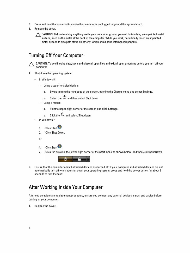
1. Click Start .
2. Click the arrow in the lower-right corner of the Start menu as shown below, and then click Shut Down..
2. Ensure that the computer and all attached devices are turned off. If your computer and attached devices did not automatically turn off when you shut down your operating system, press and hold the power button for about 6 seconds to turn them off.
After Working Inside Your ComputerAfter you complete any replacement procedure, ensure you connect any external devices, cards, and cables before turning on your computer.
1. Replace the cover.
6

CAUTION: To connect a network cable, first plug the cable into the network device and then plug it into the computer.
2. Connect any telephone or network cables to your computer.3. Connect your computer and all attached devices to their electrical outlets.4. Turn on your computer.5. If required, verify that the computer works correctly by running the Dell Diagnostics.
7
2Removing and Installing ComponentsThis section provides detailed information on how to remove or install the components from your computer.
Recommended ToolsThe procedures in this document may require the following tools:
• Small flat-blade screwdriver
• Phillips screwdriver
• Small plastic scribe
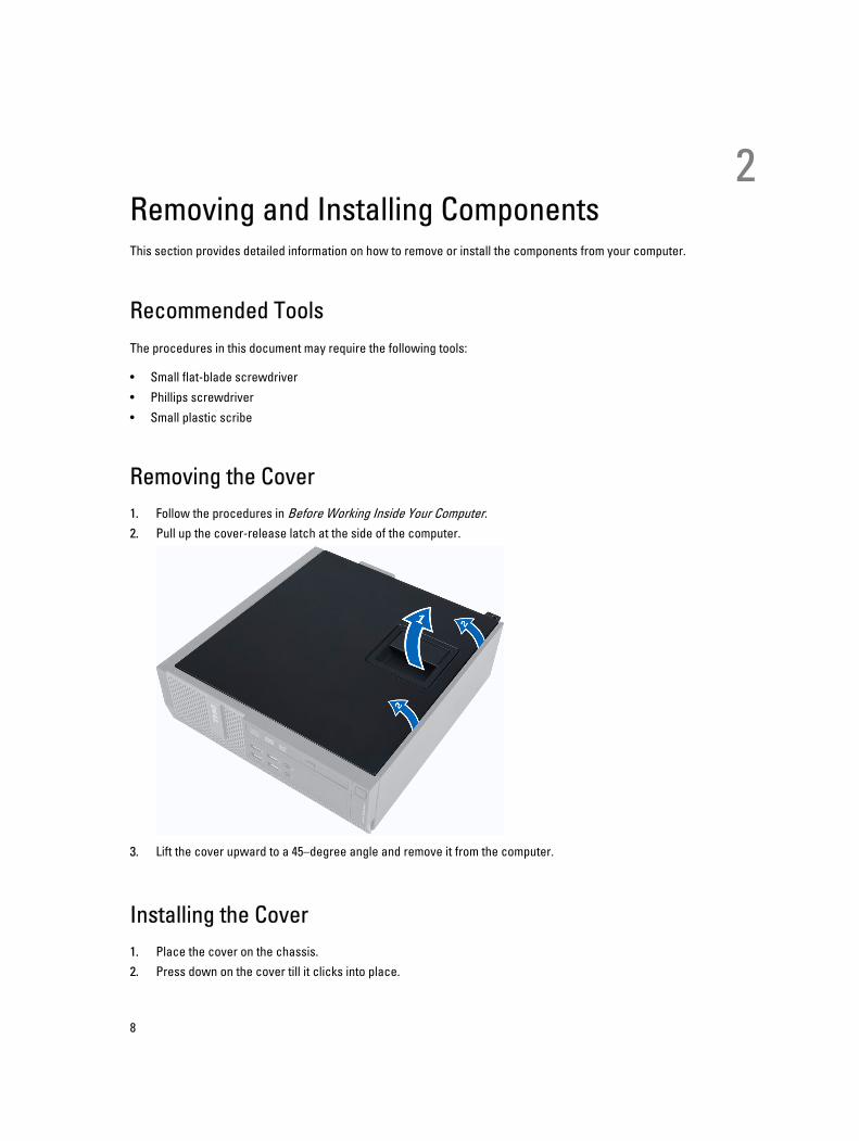
Removing the Cover1. Follow the procedures in Before Working Inside Your Computer.2. Pull up the cover-release latch at the side of the computer.
3. Lift the cover upward to a 45–degree angle and remove it from the computer.
Installing the Cover1. Place the cover on the chassis.2. Press down on the cover till it clicks into place.
8
3. Follow the procedures in After Working Inside Your Computer.
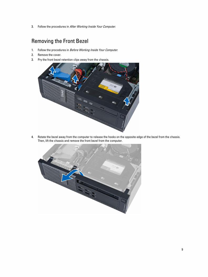
Removing the Front Bezel1. Follow the procedures in Before Working Inside Your Computer.2. Remove the cover.3. Pry the front bezel retention clips away from the chassis.
4. Rotate the bezel away from the computer to release the hooks on the opposite edge of the bezel from the chassis. Then, lift the chassis and remove the front bezel from the computer.
9
Installing the Front Bezel1. Insert the hooks along the bottom edge of the front bezel into the slots on the chassis front.2. Push the bezel toward the computer to engage the front bezel retention clips until they click into place.3. Install the cover.4. Follow the procedures in After Working Inside Your Computer.
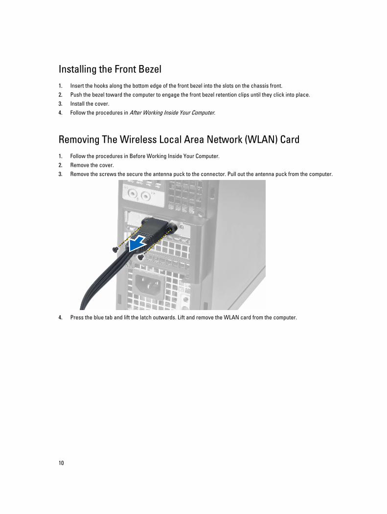
Removing The Wireless Local Area Network (WLAN) Card1. Follow the procedures in Before Working Inside Your Computer.2. Remove the cover.3. Remove the screws the secure the antenna puck to the connector. Pull out the antenna puck from the computer.
4. Press the blue tab and lift the latch outwards. Lift and remove the WLAN card from the computer.
10
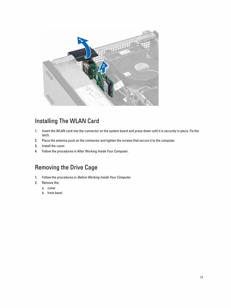
Installing The WLAN Card1. Insert the WLAN card into the connector on the system board and press down until it is securely in place. Fix the
latch.2. Place the antenna puck on the connector and tighten the screws that secure it to the computer.3. Install the cover.4. Follow the procedures in After Working Inside Your Computer.
Removing the Drive Cage1. Follow the procedures in Before Working Inside Your Computer.2. Remove the:
a. coverb. front bezel
11
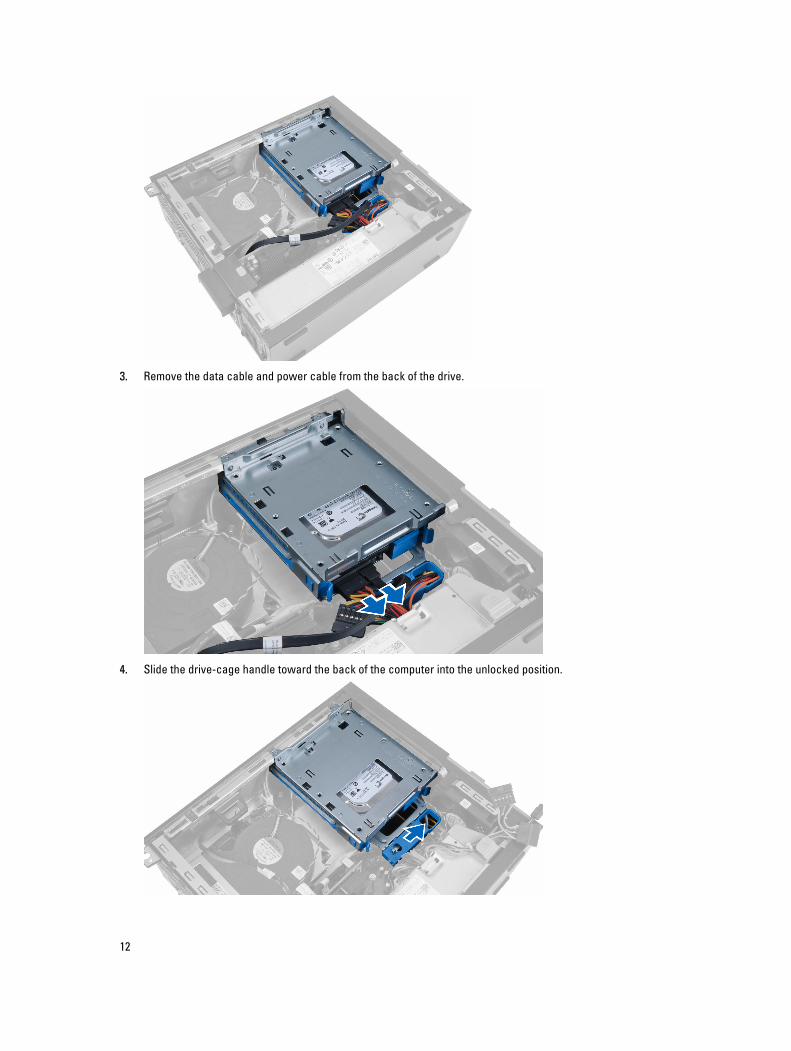
3. Remove the data cable and power cable from the back of the drive.
4. Slide the drive-cage handle toward the back of the computer into the unlocked position.
12
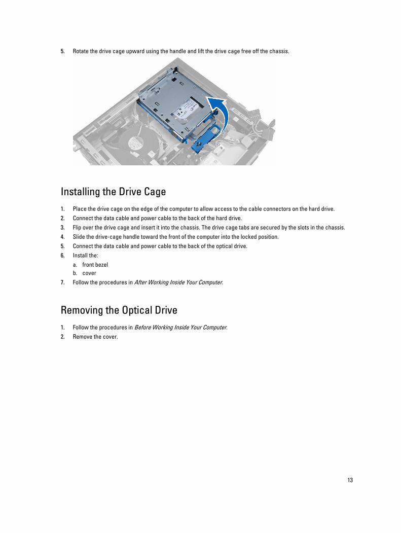
5. Rotate the drive cage upward using the handle and lift the drive cage free off the chassis.
Installing the Drive Cage1. Place the drive cage on the edge of the computer to allow access to the cable connectors on the hard drive.2. Connect the data cable and power cable to the back of the hard drive.3. Flip over the drive cage and insert it into the chassis. The drive cage tabs are secured by the slots in the chassis.4. Slide the drive-cage handle toward the front of the computer into the locked position.5. Connect the data cable and power cable to the back of the optical drive.6. Install the:
a. front bezelb. cover
7. Follow the procedures in After Working Inside Your Computer.
Removing the Optical Drive1. Follow the procedures in Before Working Inside Your Computer.2. Remove the cover.
13
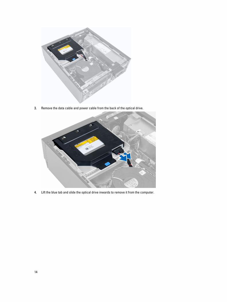
3. Remove the data cable and power cable from the back of the optical drive.
4. Lift the blue tab and slide the optical drive inwards to remove it from the computer.
14
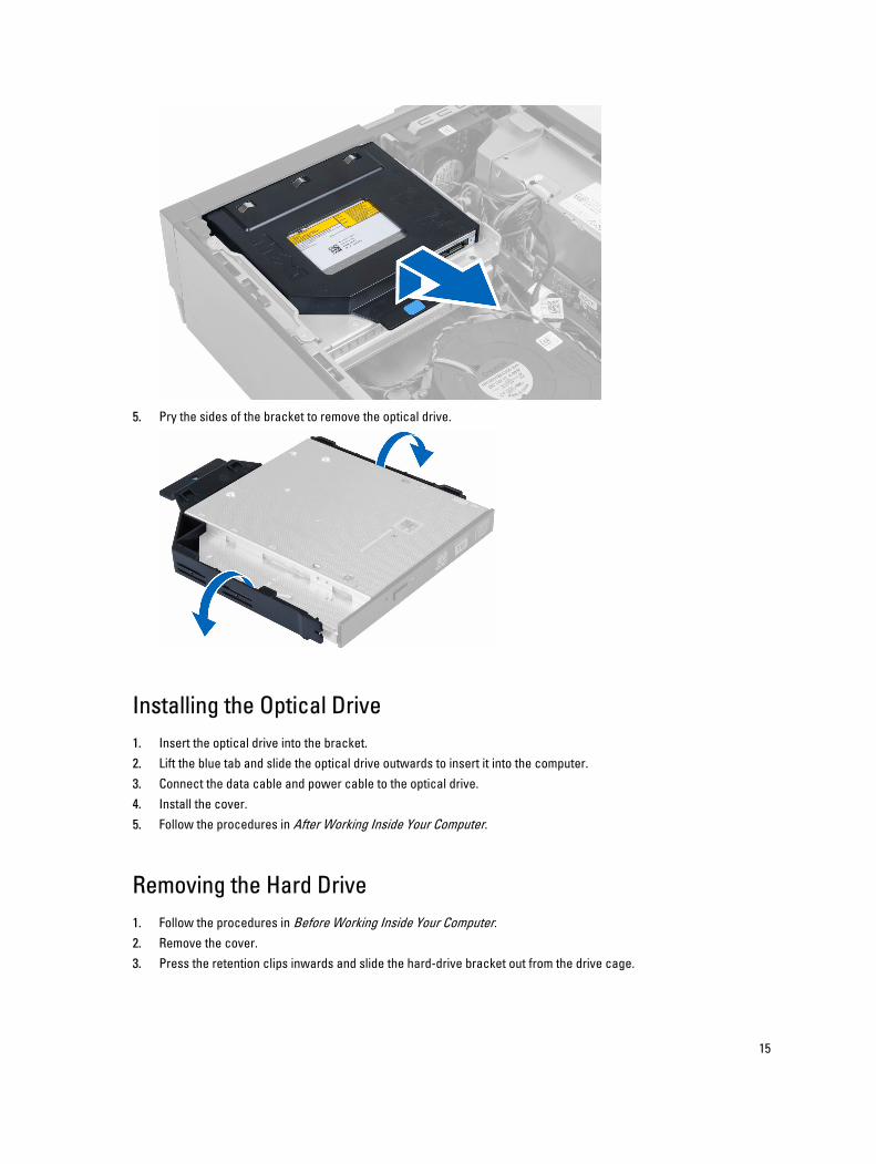
5. Pry the sides of the bracket to remove the optical drive.
Installing the Optical Drive1. Insert the optical drive into the bracket.2. Lift the blue tab and slide the optical drive outwards to insert it into the computer.3. Connect the data cable and power cable to the optical drive.4. Install the cover.5. Follow the procedures in After Working Inside Your Computer.
Removing the Hard Drive1. Follow the procedures in Before Working Inside Your Computer.2. Remove the cover.3. Press the retention clips inwards and slide the hard-drive bracket out from the drive cage.
15
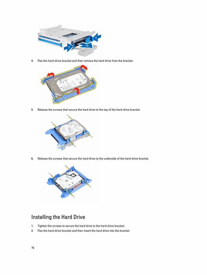
4. Flex the hard-drive bracket and then remove the hard drive from the bracket.
5. Release the screws that secure the hard drive to the top of the hard-drive bracket.
6. Release the screws that secure the hard drive to the underside of the hard-drive bracket.
Installing the Hard Drive1. Tighten the screws to secure the hard drive to the hard-drive bracket.2. Flex the hard-drive bracket and then insert the hard drive into the bracket.
16
3. Press the retention clips inwards and slide the hard-drive bracket into the drive cage.4. Install the cover.5. Follow the procedures in After Working Inside Your Computer.
Removing the Intrusion Switch1. Follow the procedures in Before Working Inside Your Computer.2. Remove the cover.
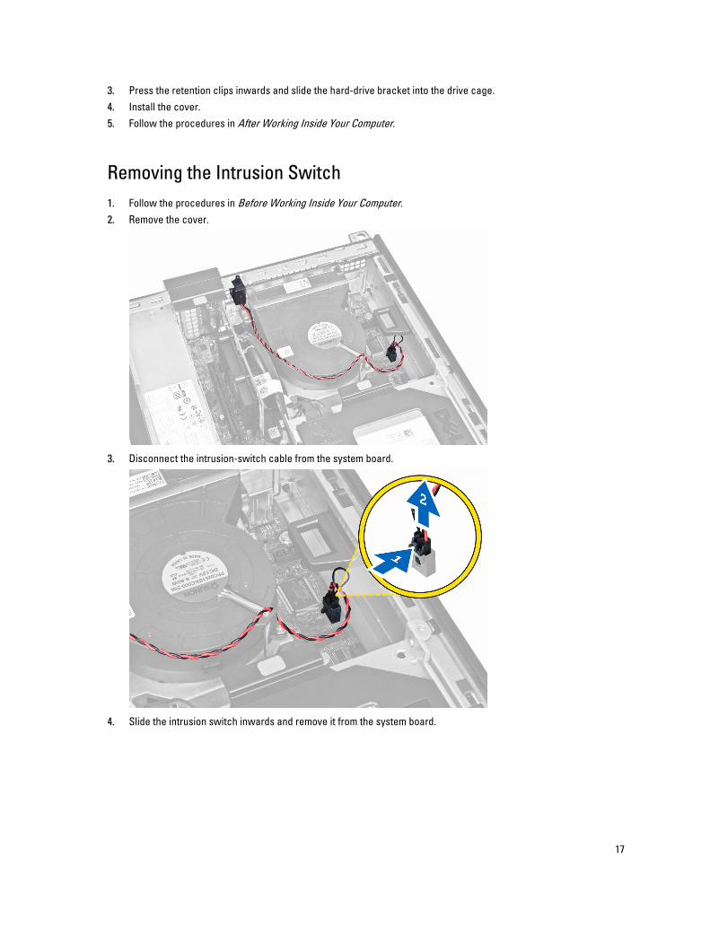
3. Disconnect the intrusion-switch cable from the system board.
4. Slide the intrusion switch inwards and remove it from the system board.
17
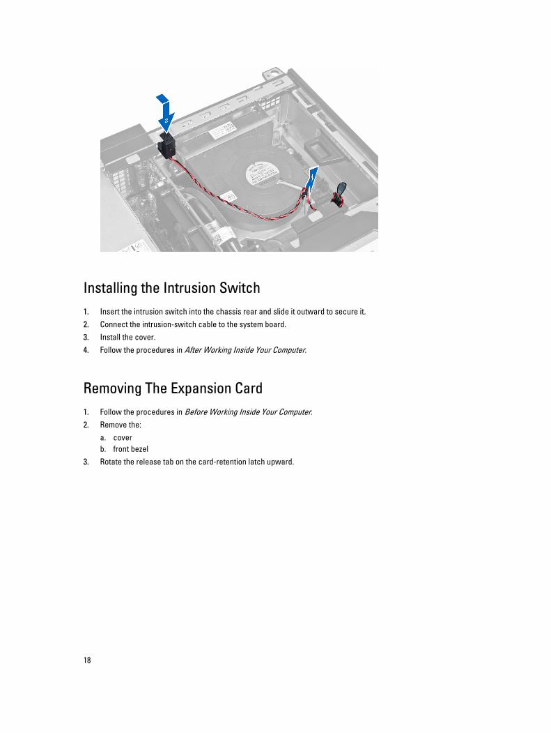
Installing the Intrusion Switch1. Insert the intrusion switch into the chassis rear and slide it outward to secure it.2. Connect the intrusion-switch cable to the system board.3. Install the cover.4. Follow the procedures in After Working Inside Your Computer.
Removing The Expansion Card1. Follow the procedures in Before Working Inside Your Computer.2. Remove the:
a. coverb. front bezel
3. Rotate the release tab on the card-retention latch upward.
18
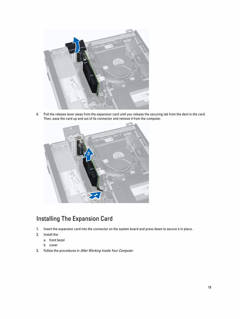
4. Pull the release lever away from the expansion card until you release the securing tab from the dent in the card. Then, ease the card up and out of its connector and remove it from the computer.
Installing The Expansion Card1. Insert the expansion card into the connector on the system board and press down to secure it in place.2. Install the:
a. front bezelb. cover
3. Follow the procedures in After Working Inside Your Computer.
19
Memory Module GuidelinesTo ensure optimal performance of your computer, observe the following general guidelines when configuring your system memory:
• Memory modules of different sizes can be mixed (for example, 2 GB and 4 GB). But, all populated channels must have identical configurations.
• Memory modules must be installed beginning with the first socket.
NOTE: The memory sockets in your computer may be labeled differently depending on the hardware configuration. For example, A1, A2 or 1,2,3.
• If the quad-rank memory modules are mixed with single or dual-rank modules, the quad-rank modules must be installed in the sockets with the white release levers.
• If memory modules with different speeds are installed, they operate at the speed of the slowest installed memory modules.
Removing the Memory1. Follow the procedures in Before Working Inside Your Computer.2. Remove the:
a. coverb. front bezelc. drive cage
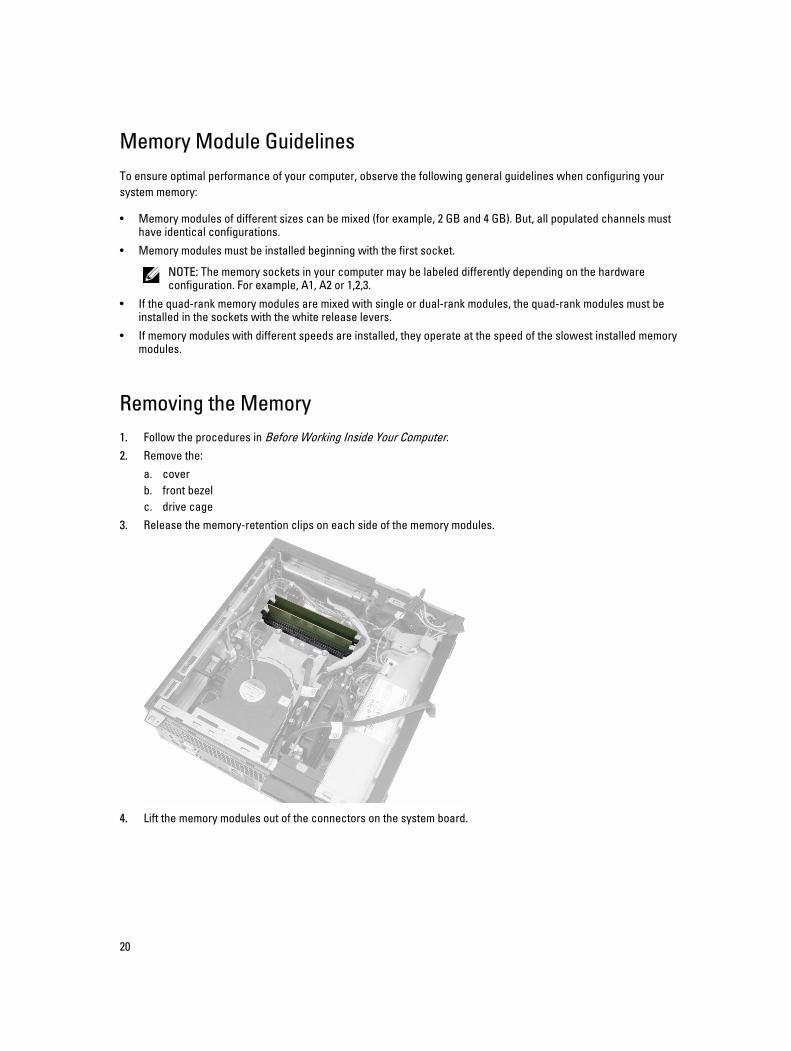
3. Release the memory-retention clips on each side of the memory modules.
4. Lift the memory modules out of the connectors on the system board.
20
Installing the Memory1. Insert the memory modules into the connectors on the system board.2. Press down on the memory modules until the retention clips spring back to secure them in place.3. Install the:
a. drive cageb. front bezelc. cover
4. Follow the procedures in After Working Inside Your Computer.
Removing the Coin-Cell Battery1. Follow the procedures in Before Working Inside Your Computer.2. Remove the:
a. coverb. front bezel
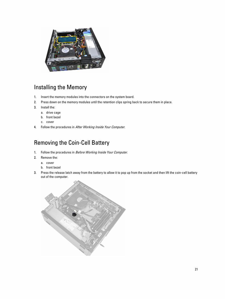
3. Press the release latch away from the battery to allow it to pop up from the socket and then lift the coin-cell battery out of the computer.
21
Installing the Coin-Cell Battery1. Place the coin-cell battery into its slot on the system board.2. Press the coin-cell battery downward till the release latch springs back into place and secures it.3. Install the:
a. front bezelb. cover
4. Follow the procedures in After Working Inside Your Computer.
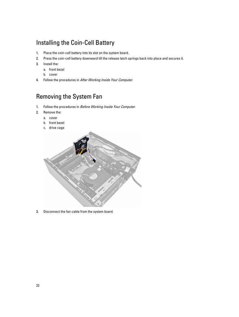
Removing the System Fan1. Follow the procedures in Before Working Inside Your Computer.2. Remove the:
a. coverb. front bezelc. drive cage
3. Disconnect the fan cable from the system board.
22
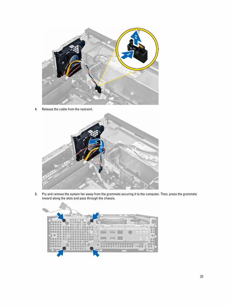
4. Release the cable from the restraint.
5. Pry and remove the system fan away from the grommets securing it to the computer. Then, press the grommets inward along the slots and pass through the chassis.
23
Installing the System Fan1. Place the system fan in the chassis.2. Pass the grommets through the chassis and slide outward along the grooves to secure them in place.3. Thread the fan cable through the restraint and connect it to the system board.4. Install the:
a. drive cageb. front bezelc. cover
5. Follow the procedures in After Working Inside Your Computer.
Removing the Speaker1. Follow the procedures in Before Working Inside Your Computer.2. Remove the:
a. coverb. front bezelc. drive cage
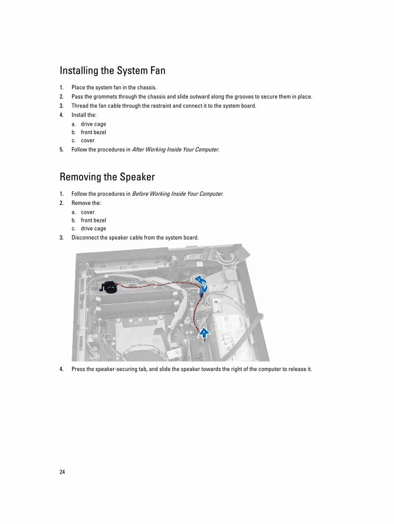
3. Disconnect the speaker cable from the system board.
4. Press the speaker-securing tab, and slide the speaker towards the right of the computer to release it.
24
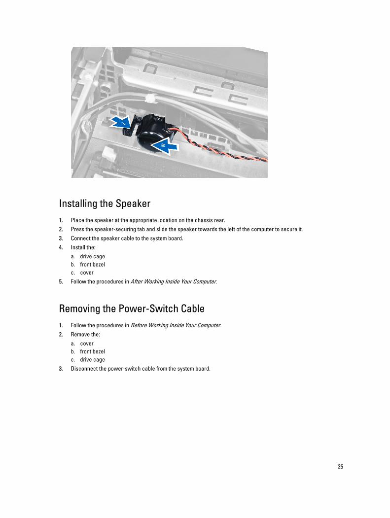
Installing the Speaker1. Place the speaker at the appropriate location on the chassis rear.2. Press the speaker-securing tab and slide the speaker towards the left of the computer to secure it.3. Connect the speaker cable to the system board.4. Install the:
a. drive cageb. front bezelc. cover
5. Follow the procedures in After Working Inside Your Computer.
Removing the Power-Switch Cable1. Follow the procedures in Before Working Inside Your Computer.2. Remove the:
a. coverb. front bezelc. drive cage
3. Disconnect the power-switch cable from the system board.
25
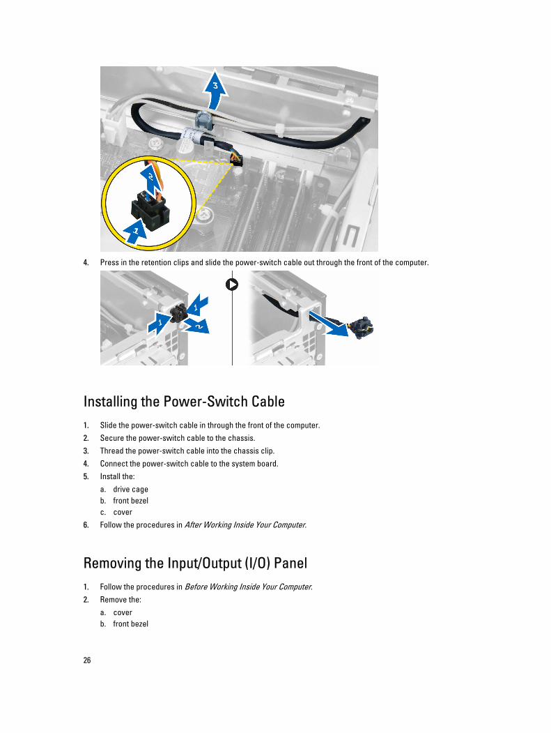
4. Press in the retention clips and slide the power-switch cable out through the front of the computer.
Installing the Power-Switch Cable1. Slide the power-switch cable in through the front of the computer.2. Secure the power-switch cable to the chassis.3. Thread the power-switch cable into the chassis clip.4. Connect the power-switch cable to the system board.5. Install the:
a. drive cageb. front bezelc. cover
6. Follow the procedures in After Working Inside Your Computer.
Removing the Input/Output (I/O) Panel1. Follow the procedures in Before Working Inside Your Computer.2. Remove the:
a. coverb. front bezel
26
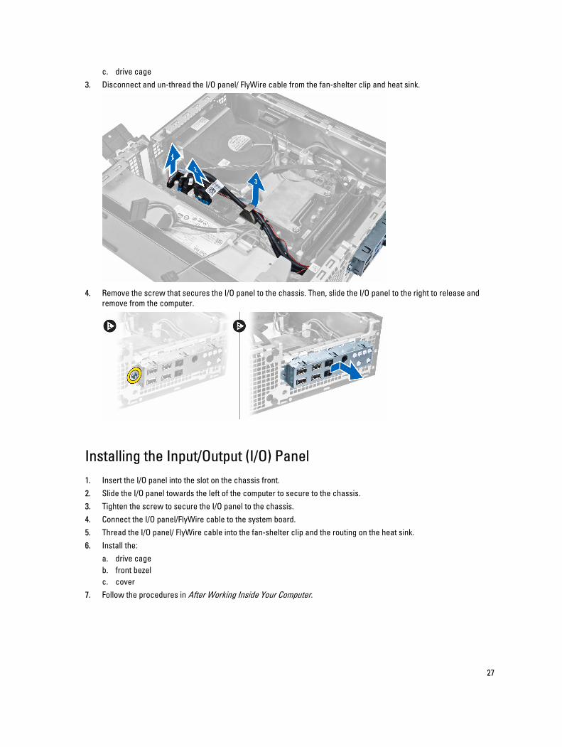
c. drive cage3. Disconnect and un-thread the I/O panel/ FlyWire cable from the fan-shelter clip and heat sink.
4. Remove the screw that secures the I/O panel to the chassis. Then, slide the I/O panel to the right to release and remove from the computer.
Installing the Input/Output (I/O) Panel1. Insert the I/O panel into the slot on the chassis front.2. Slide the I/O panel towards the left of the computer to secure to the chassis.3. Tighten the screw to secure the I/O panel to the chassis.4. Connect the I/O panel/FlyWire cable to the system board.5. Thread the I/O panel/ FlyWire cable into the fan-shelter clip and the routing on the heat sink.6. Install the:
a. drive cageb. front bezelc. cover
7. Follow the procedures in After Working Inside Your Computer.
27
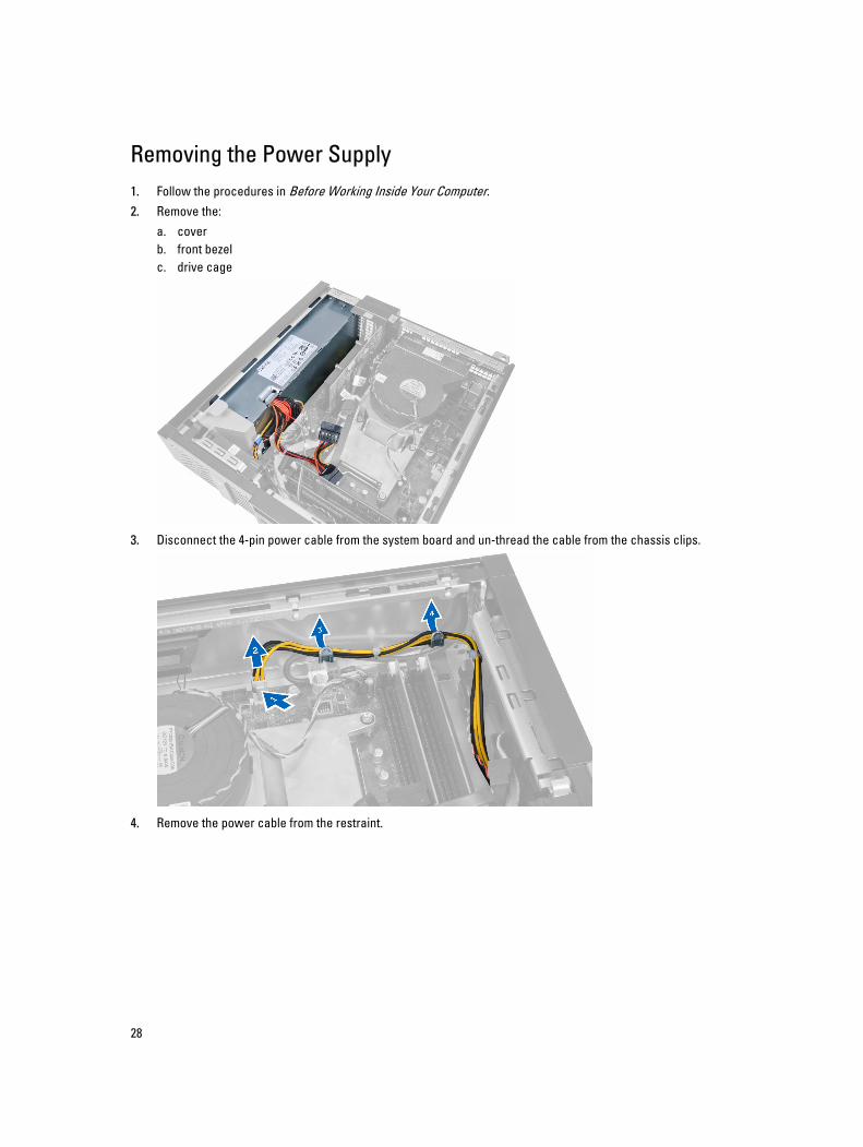
Removing the Power Supply1. Follow the procedures in Before Working Inside Your Computer.2. Remove the:
a. coverb. front bezelc. drive cage
3. Disconnect the 4-pin power cable from the system board and un-thread the cable from the chassis clips.
4. Remove the power cable from the restraint.
28
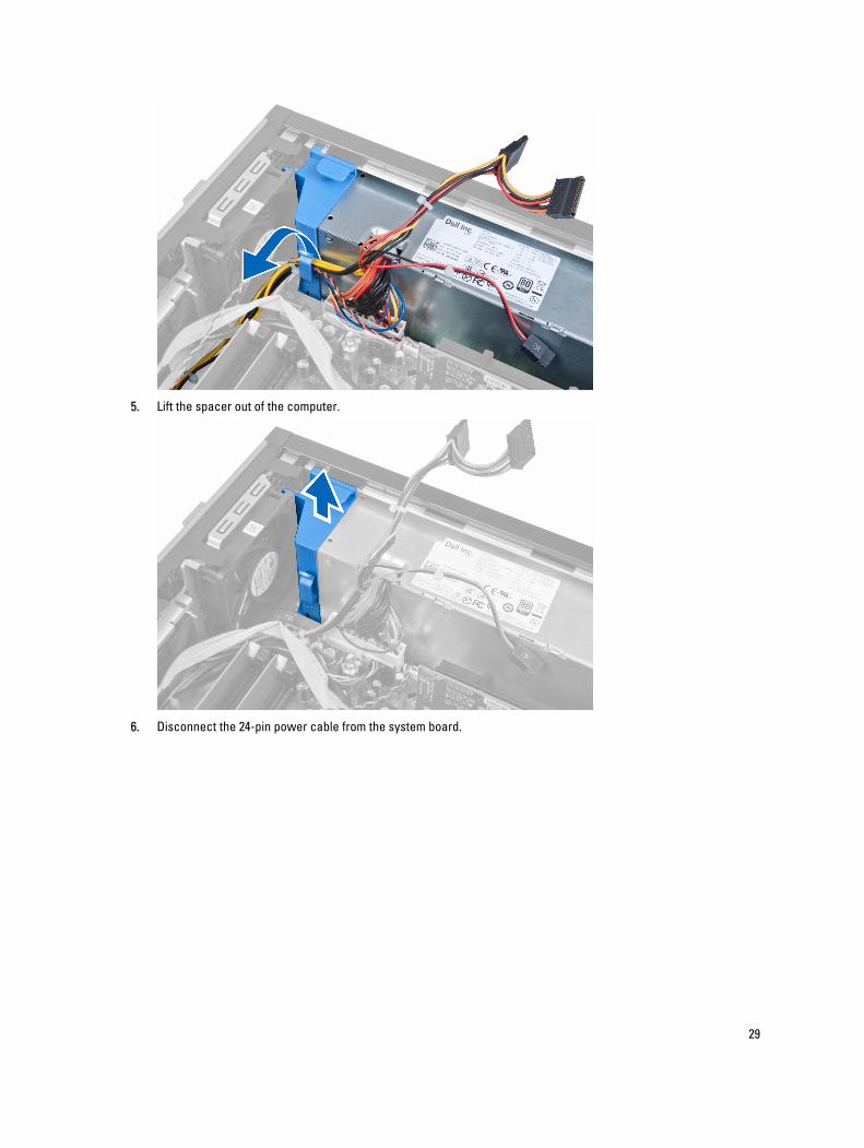
5. Lift the spacer out of the computer.
6. Disconnect the 24-pin power cable from the system board.
29
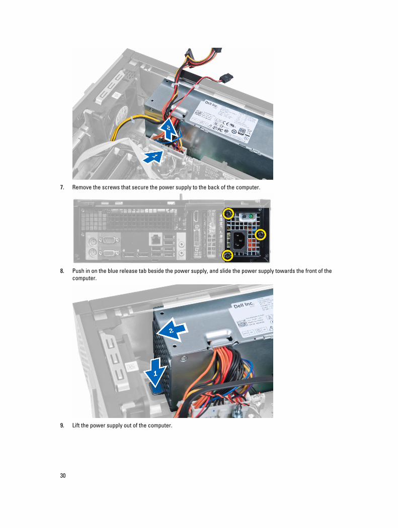
7. Remove the screws that secure the power supply to the back of the computer.
8. Push in on the blue release tab beside the power supply, and slide the power supply towards the front of the computer.
9. Lift the power supply out of the computer.
30
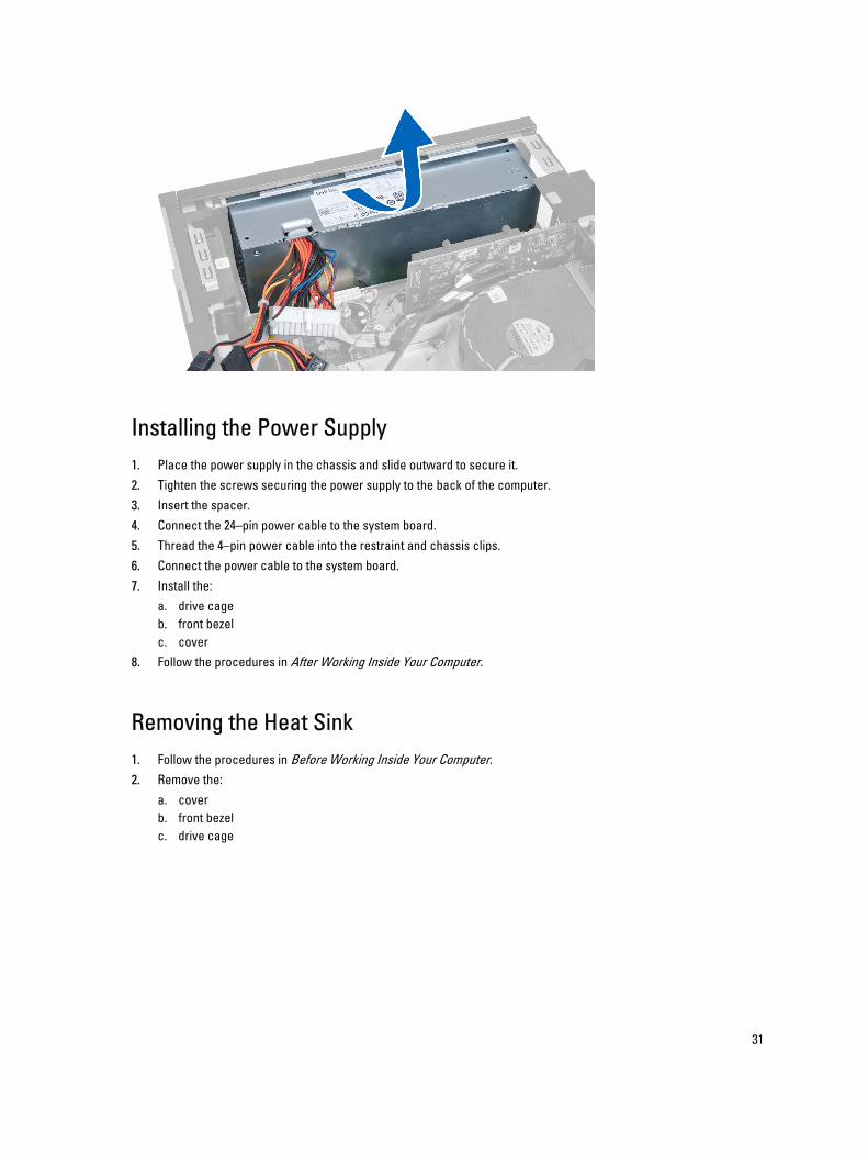
Installing the Power Supply1. Place the power supply in the chassis and slide outward to secure it.2. Tighten the screws securing the power supply to the back of the computer.3. Insert the spacer.4. Connect the 24–pin power cable to the system board.5. Thread the 4–pin power cable into the restraint and chassis clips.6. Connect the power cable to the system board.7. Install the:
a. drive cageb. front bezelc. cover
8. Follow the procedures in After Working Inside Your Computer.
Removing the Heat Sink 1. Follow the procedures in Before Working Inside Your Computer.2. Remove the:
a. coverb. front bezelc. drive cage
31
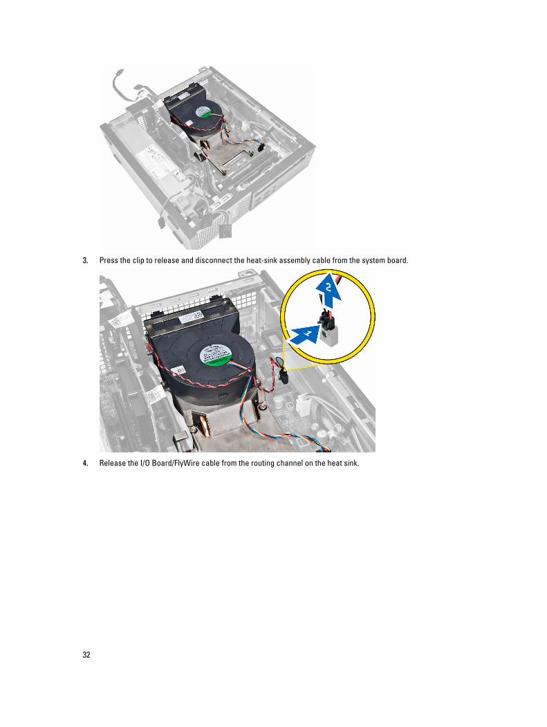
3. Press the clip to release and disconnect the heat-sink assembly cable from the system board.
4. Release the I/O Board/FlyWire cable from the routing channel on the heat sink.
32
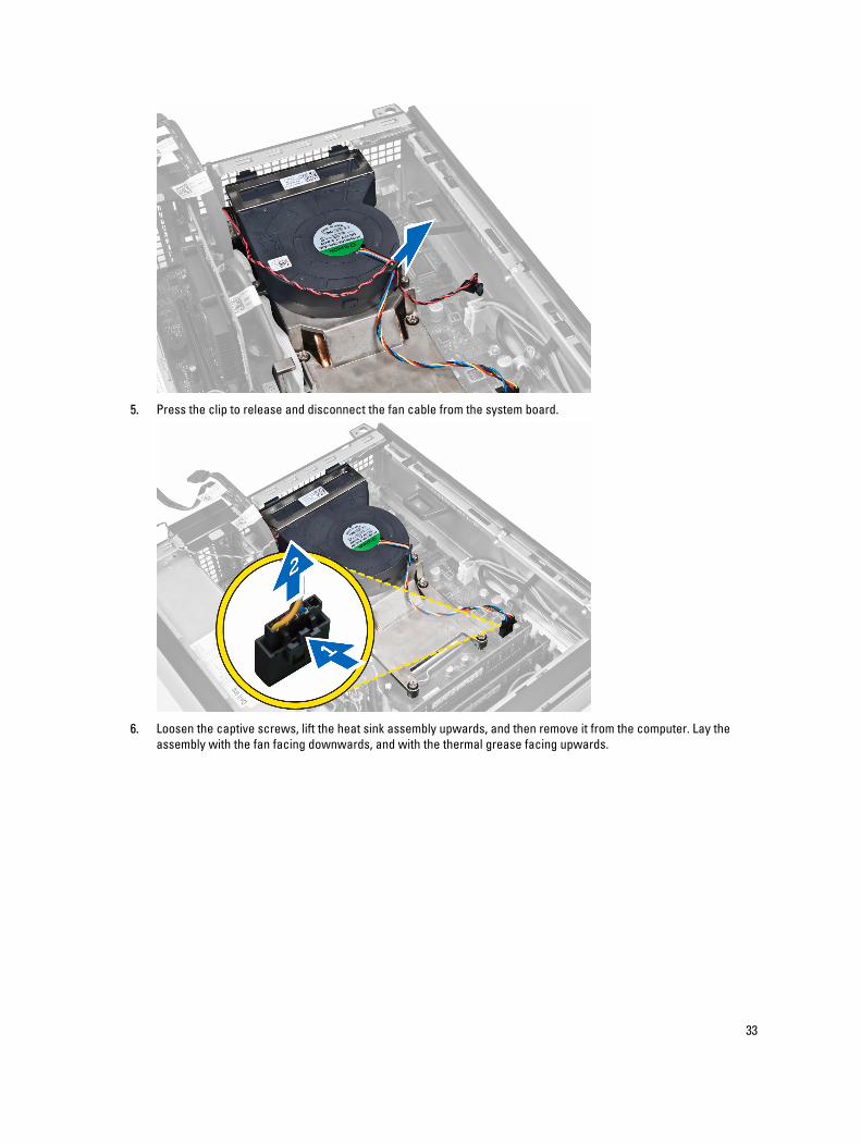
5. Press the clip to release and disconnect the fan cable from the system board.
6. Loosen the captive screws, lift the heat sink assembly upwards, and then remove it from the computer. Lay the assembly with the fan facing downwards, and with the thermal grease facing upwards.
33
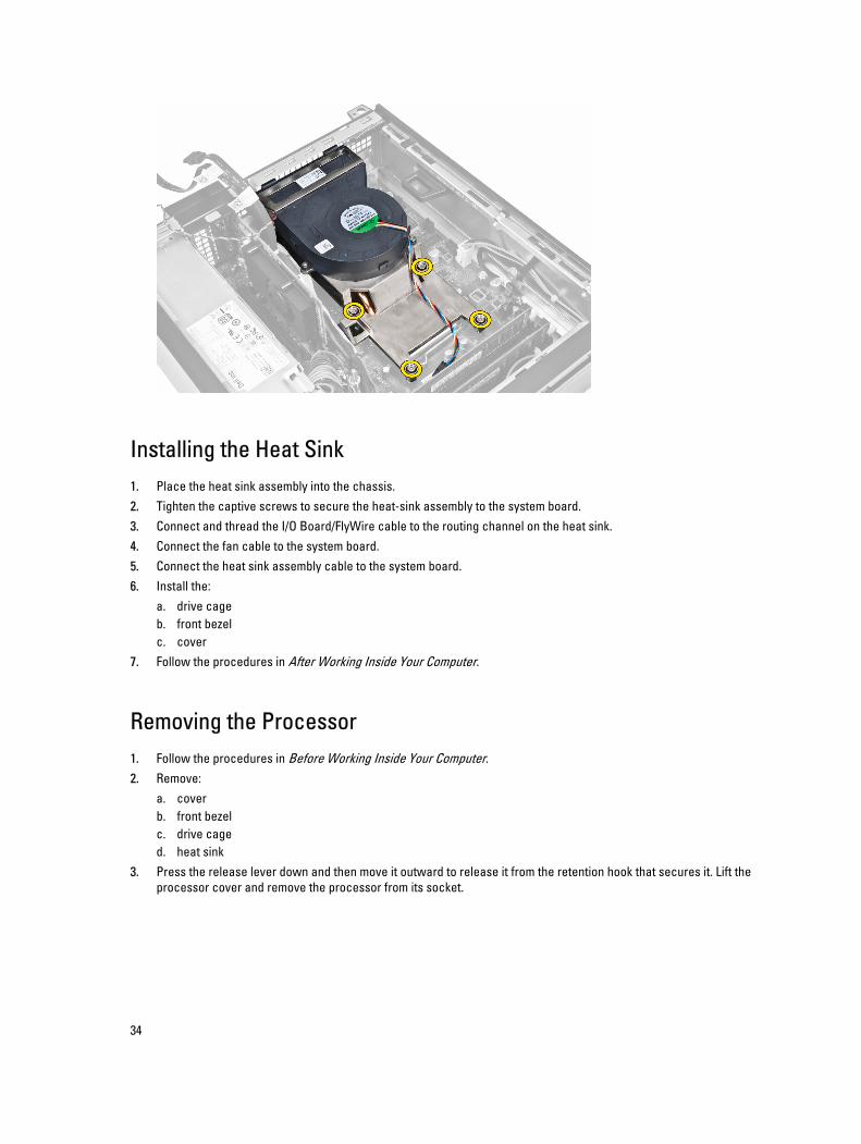
Installing the Heat Sink1. Place the heat sink assembly into the chassis.2. Tighten the captive screws to secure the heat-sink assembly to the system board.3. Connect and thread the I/O Board/FlyWire cable to the routing channel on the heat sink.4. Connect the fan cable to the system board.5. Connect the heat sink assembly cable to the system board.6. Install the:
a. drive cageb. front bezelc. cover
7. Follow the procedures in After Working Inside Your Computer.
Removing the Processor1. Follow the procedures in Before Working Inside Your Computer.2. Remove:
a. coverb. front bezelc. drive caged. heat sink
3. Press the release lever down and then move it outward to release it from the retention hook that secures it. Lift the processor cover and remove the processor from its socket.
34
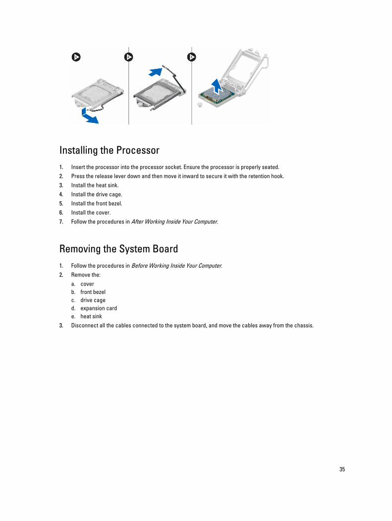
Installing the Processor1. Insert the processor into the processor socket. Ensure the processor is properly seated.2. Press the release lever down and then move it inward to secure it with the retention hook.3. Install the heat sink.4. Install the drive cage.5. Install the front bezel.6. Install the cover.7. Follow the procedures in After Working Inside Your Computer.
Removing the System Board1. Follow the procedures in Before Working Inside Your Computer.2. Remove the:
a. coverb. front bezelc. drive caged. expansion carde. heat sink
3. Disconnect all the cables connected to the system board, and move the cables away from the chassis.
35
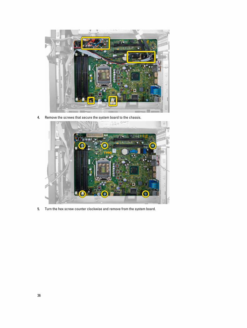
4. Remove the screws that secure the system board to the chassis.
5. Turn the hex screw counter clockwise and remove from the system board.
36
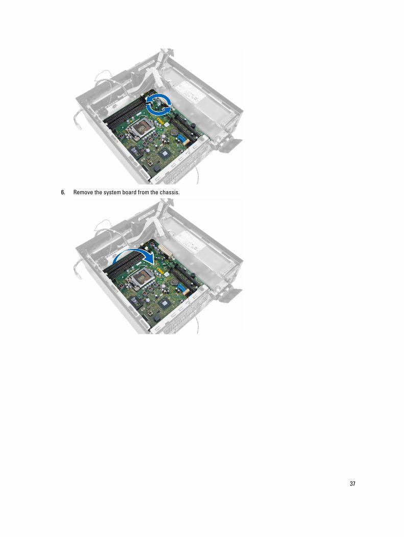
6. Remove the system board from the chassis.
37
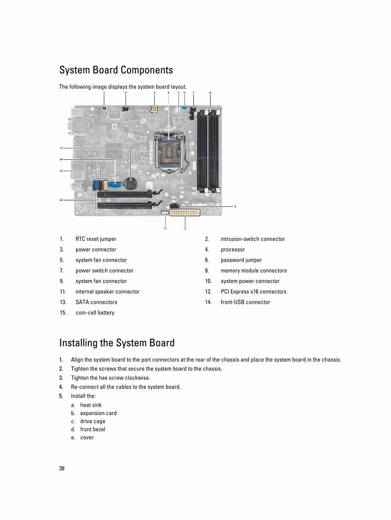
System Board ComponentsThe following image displays the system board layout.
1. RTC reset jumper 2. intrusion-switch connector
3. power connector 4. processor
5. system fan connector 6. password jumper
7. power switch connector 8. memory module connectors
9. system fan connector 10. system power connector
11. internal speaker connector 12. PCI Express x16 connectors
13. SATA connectors 14. front-USB connector
15. coin-cell battery
Installing the System Board1. Align the system board to the port connectors at the rear of the chassis and place the system board in the chassis.2. Tighten the screws that secure the system board to the chassis.3. Tighten the hex screw clockwise.4. Re-connect all the cables to the system board.5. Install the:
a. heat sinkb. expansion cardc. drive caged. front bezele. cover
38

6. Follow the procedures in After Working Inside Your Computer.
39
3System SetupSystem Setup enables you to manage your computer hardware and specify BIOS‐level options. From the System Setup, you can:
• Change the NVRAM settings after you add or remove hardware
• View the system hardware configuration
• Enable or disable integrated devices
• Set performance and power management thresholds
• Manage your computer security
Boot SequenceBoot Sequence allows you to bypass the System Setup‐defined boot device order and boot directly to a specific device (for example: optical drive or hard drive). During the Power-on Self Test (POST), when the Dell logo appears, you can:
• Access System Setup by pressing <F2> key
• Bring up the one-time boot menu by pressing <F12> key
The one-time boot menu displays the devices that you can boot from including the diagnostic option. The boot-menu options are:
• Removable Drive (if available)
• STXXXX Drive
NOTE: XXX denotes the SATA drive number.
• Optical Drive
• Diagnostics
NOTE: Choosing Diagnostics, will display the ePSA diagnostics screen.
The boot sequence screen also displays the option to access the System Setup screen.
Navigation KeysThe following table displays the system setup navigation keys.
NOTE: For most of the system setup options, changes that you make are recorded but do not take effect until you re-start the system.
40
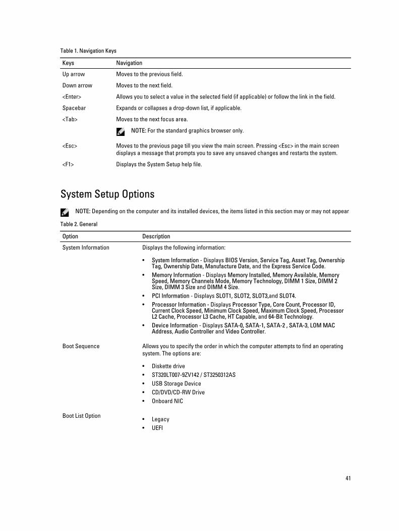
Table 1. Navigation Keys
Keys Navigation
Up arrow Moves to the previous field.
Down arrow Moves to the next field.
<Enter> Allows you to select a value in the selected field (if applicable) or follow the link in the field.
Spacebar Expands or collapses a drop‐down list, if applicable.
<Tab> Moves to the next focus area.
NOTE: For the standard graphics browser only.
<Esc> Moves to the previous page till you view the main screen. Pressing <Esc> in the main screen displays a message that prompts you to save any unsaved changes and restarts the system.
<F1> Displays the System Setup help file.
System Setup OptionsNOTE: Depending on the computer and its installed devices, the items listed in this section may or may not appear
Table 2. General
Option Description
System Information Displays the following information:
• System Information - Displays BIOS Version, Service Tag, Asset Tag, Ownership Tag, Ownership Date, Manufacture Date, and the Express Service Code.
• Memory Information - Displays Memory Installed, Memory Available, Memory Speed, Memory Channels Mode, Memory Technology, DIMM 1 Size, DIMM 2 Size, DIMM 3 Size and DIMM 4 Size.
• PCI Information - Displays SLOT1, SLOT2, SLOT3,and SLOT4.• Processor Information - Displays Processor Type, Core Count, Processor ID,
Current Clock Speed, Minimum Clock Speed, Maximum Clock Speed, Processor L2 Cache, Processor L3 Cache, HT Capable, and 64-Bit Technology.
• Device Information - Displays SATA-0, SATA-1, SATA-2 , SATA-3, LOM MAC Address, Audio Controller and Video Controller.
Boot Sequence Allows you to specify the order in which the computer attempts to find an operating system. The options are:
• Diskette drive• ST320LT007-9ZV142 / ST3250312AS• USB Storage Device• CD/DVD/CD-RW Drive• Onboard NIC
Boot List Option • Legacy• UEFI
41
Option Description
Date/Time Allows you to set the date and time. The changes to the system date and time takes effect immediately.
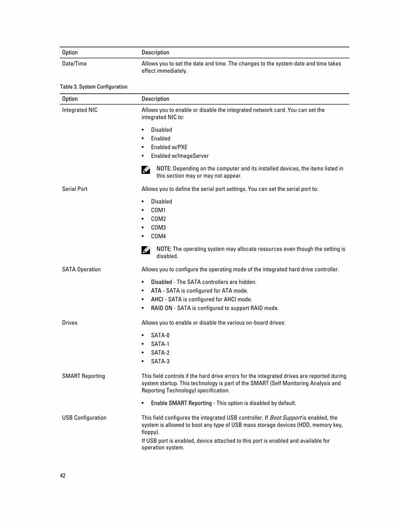
Table 3. System Configuration
Option Description
Integrated NIC Allows you to enable or disable the integrated network card. You can set the integrated NIC to:
• Disabled• Enabled• Enabled w/PXE• Enabled w/ImageServer
NOTE: Depending on the computer and its installed devices, the items listed in this section may or may not appear.
Serial Port Allows you to define the serial port settings. You can set the serial port to:
• Disabled• COM1• COM2• COM3• COM4
NOTE: The operating system may allocate resources even though the setting is disabled.
SATA Operation Allows you to configure the operating mode of the integrated hard drive controller.
• Disabled - The SATA controllers are hidden.• ATA - SATA is configured for ATA mode.• AHCI - SATA is configured for AHCI mode.• RAID ON - SATA is configured to support RAID mode.
Drives Allows you to enable or disable the various on-board drives:
• SATA-0• SATA-1• SATA-2• SATA-3
SMART Reporting This field controls if the hard drive errors for the integrated drives are reported during system startup. This technology is part of the SMART (Self Monitoring Analysis and Reporting Technology) specification.
• Enable SMART Reporting - This option is disabled by default.
USB Configuration This field configures the integrated USB controller. If Boot Support is enabled, the system is allowed to boot any type of USB mass storage devices (HDD, memory key, floppy).If USB port is enabled, device attached to this port is enabled and available for operation system.
42
Option Description
If USB port is disabled, the operation system cannot see any device attached to this port.The options for USB configuration differ based on the form factors:For Mini-Tower, Desktop, Small Form Factor the options are:
• Enable Boot Support• Enable Rear Dual USB Ports• Enable Rear Quad USB Ports• Enable Front USB Ports
For Ultra Small Form Factor, the options are:
• Enable Boot Support• Enable Rear Dual USB 2.0 Ports• Enable Rear Dual USB 3.0 Ports• Enable Front USB Ports
NOTE: USB keyboard and mouse always work in the BIOS setup irrespective of these settings.
Miscellaneous Devices Allows you to enable or disable various on-board devices.
• Enable PCI Slot - This option is enabled by default.
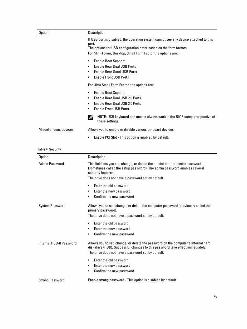
Table 4. Security
Option Description
Admin Password This field lets you set, change, or delete the administrator (admin) password (sometimes called the setup password). The admin password enables several security features.The drive does not have a password set by default.
• Enter the old password• Enter the new password• Confirm the new password
System Password Allows you to set, change, or delete the computer password (previously called the primary password).The drive does not have a password set by default.
• Enter the old password• Enter the new password• Confirm the new password
Internal HDD-0 Password Allows you to set, change, or delete the password on the computer's internal hard disk drive (HDD). Successful changes to this password take effect immediately.The drive does not have a password set by default.
• Enter the old password• Enter the new password• Confirm the new password
Strong Password Enable strong password - This option is disabled by default.
43
Option Description
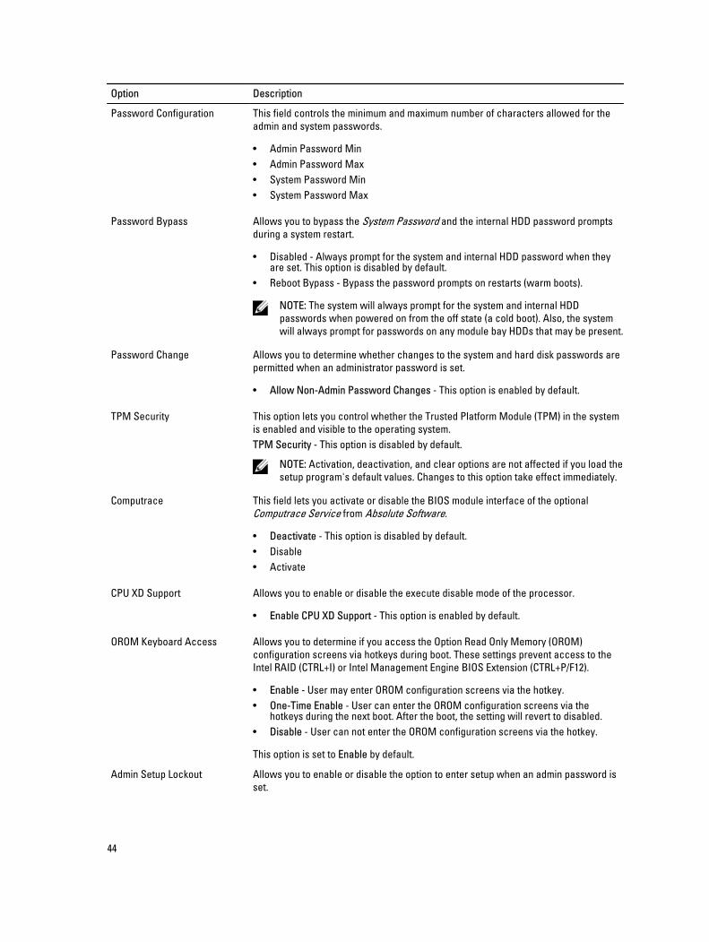
Password Configuration This field controls the minimum and maximum number of characters allowed for the admin and system passwords.
• Admin Password Min• Admin Password Max• System Password Min• System Password Max
Password Bypass Allows you to bypass the System Password and the internal HDD password prompts during a system restart.
• Disabled - Always prompt for the system and internal HDD password when they are set. This option is disabled by default.
• Reboot Bypass - Bypass the password prompts on restarts (warm boots).
NOTE: The system will always prompt for the system and internal HDD passwords when powered on from the off state (a cold boot). Also, the system will always prompt for passwords on any module bay HDDs that may be present.
Password Change Allows you to determine whether changes to the system and hard disk passwords are permitted when an administrator password is set.
• Allow Non-Admin Password Changes - This option is enabled by default.
TPM Security This option lets you control whether the Trusted Platform Module (TPM) in the system is enabled and visible to the operating system.TPM Security - This option is disabled by default.
NOTE: Activation, deactivation, and clear options are not affected if you load the setup program's default values. Changes to this option take effect immediately.
Computrace This field lets you activate or disable the BIOS module interface of the optional Computrace Service from Absolute Software.
• Deactivate - This option is disabled by default.• Disable• Activate
CPU XD Support Allows you to enable or disable the execute disable mode of the processor.
• Enable CPU XD Support - This option is enabled by default.
OROM Keyboard Access Allows you to determine if you access the Option Read Only Memory (OROM) configuration screens via hotkeys during boot. These settings prevent access to the Intel RAID (CTRL+I) or Intel Management Engine BIOS Extension (CTRL+P/F12).
• Enable - User may enter OROM configuration screens via the hotkey.• One-Time Enable - User can enter the OROM configuration screens via the
hotkeys during the next boot. After the boot, the setting will revert to disabled.• Disable - User can not enter the OROM configuration screens via the hotkey.
This option is set to Enable by default.
Admin Setup Lockout Allows you to enable or disable the option to enter setup when an admin password is set.
44
Option Description
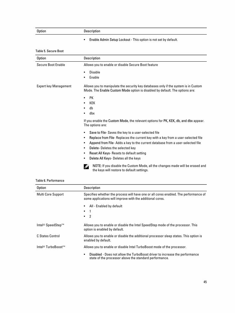
• Enable Admin Setup Lockout - This option is not set by default.
Table 5. Secure Boot
Option Description
Secure Boot Enable Allows you to enable or disable Secure Boot feature
• Disable• Enable
Expert key Management Allows you to manipulate the security key databases only if the system is in Custom Mode. The Enable Custom Mode option is disabled by default. The options are:
• PK• KEK• db• dbx
If you enable the Custom Mode, the relevant options for PK, KEK, db, and dbx appear. The options are:
• Save to File- Saves the key to a user-selected file• Replace from File- Replaces the current key with a key from a user-selected file• Append from File- Adds a key to the current database from a user-selected file• Delete- Deletes the selected key• Reset All Keys- Resets to default setting• Delete All Keys- Deletes all the keys
NOTE: If you disable the Custom Mode, all the changes made will be erased and the keys will restore to default settings.
Table 6. Performance
Option Description
Multi Core Support Specifies whether the process will have one or all cores enabled. The performance of some applications will improve with the additional cores.
• All - Enabled by default• 1• 2
Intel® SpeedStep™ Allows you to enable or disable the Intel SpeedStep mode of the processor. This option is enabled by default.
C States Control Allows you to enable or disable the additional processor sleep states. This option is enabled by default.
Intel® TurboBoost™ Allows you to enable or disable Intel TurboBoost mode of the processor.
• Disabled - Does not allow the TurboBoost driver to increase the performance state of the processor above the standard performance.
45
Option Description
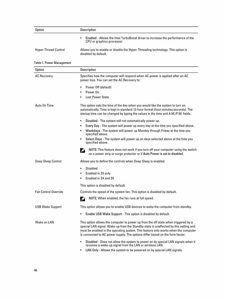
• Enabled - Allows the Intel TurboBoost driver to increase the performance of the CPU or graphics processor.
Hyper-Thread Control Allows you to enable or disable the Hyper-Threading technology. This option is disabled by default.
Table 7. Power Management
Option Description
AC Recovery Specifies how the computer will respond when AC power is applied after an AC power loss. You can set the AC Recovery to:
• Power Off (default)• Power On• Last Power State
Auto On Time This option sets the time of the day when you would like the system to turn on automatically. Time is kept in standard 12-hour format (hour:minutes:seconds). The startup time can be changed by typing the values in the time and A.M./P.M. fields.
• Disabled - The system will not automatically power up.• Every Day - The system will power up every day at the time you specified above .• Weekdays - The system will power up Monday through Friday at the time you
specified above.• Select Days - The system will power up on days selected above at the time you
specified above.
NOTE: This feature does not work if you turn off your computer using the switch on a power strip or surge protector or if Auto Power is set to disabled.
Deep Sleep Control Allows you to define the controls when Deep Sleep is enabled.
• Disabled• Enabled in S5 only• Enabled in S4 and S5
This option is disabled by default.
Fan Control Override Controls the speed of the system fan. This option is disabled by default.
NOTE: When enabled, the fan runs at full speed.
USB Wake Support This option allows you to enable USB devices to wake the computer from standby.
• Enable USB Wake Support - This option is disabled by default.
Wake on LAN This option allows the computer to power up from the off state when triggered by a special LAN signal. Wake-up from the Standby state is unaffected by this setting and must be enabled in the operating system. This feature only works when the computer is connected to AC power supply. The options differ based on the form factor.
• Disabled - Does not allow the system to power on by special LAN signals when it receives a wake-up signal from the LAN or wireless LAN.
• LAN Only - Allows the system to be powered on by special LAN signals.
46
Option Description
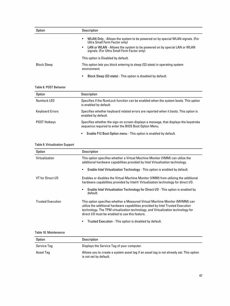
• WLAN Only - Allows the system to be powered on by special WLAN signals. (For Ultra Small Form Factor only)
• LAN or WLAN - Allows the system to be powered on by special LAN or WLAN signals. (For Ultra Small Form Factor only)
This option is Disabled by default.
Block Sleep This option lets you block entering to sleep (S3 state) in operating system environment.
• Block Sleep (S3 state) - This option is disabled by default.
Table 8. POST Behavior
Option Description
Numlock LED Specifies if the NumLock function can be enabled when the system boots. This option is enabled by default.
Keyboard Errors Specifies whether keyboard related errors are reported when it boots. This option is enabled by default.
POST Hotkeys Specifies whether the sign-on screen displays a message, that displays the keystroke sequence required to enter the BIOS Boot Option Menu.
• Enable F12 Boot Option menu - This option is enabled by default.
Table 9. Virtualization Support
Option Description
Virtualization This option specifies whether a Virtual Machine Monitor (VMM) can utilize the additional hardware capabilities provided by Intel Virtualization technology.
• Enable Intel Virtualization Technology - This option is enabled by default.
VT for Direct I/O Enables or disables the Virtual Machine Monitor (VMM) from utilizing the additional hardware capabilities provided by Intel® Virtualization technology for direct I/O.
• Enable Intel Virtualization Technology for Direct I/O - This option is enabled by default.
Trusted Execution This option specifies whether a Measured Virtual Machine Monitor (MVMM) can utilize the additional hardware capabilities provided by Intel Trusted Execution technology. The TPM virtualization technology, and Virtualization technology for direct I/O must be enabled to use this feature.
• Trusted Execution - This option is disabled by default.
Table 10. Maintenance
Option Description
Service Tag Displays the Service Tag of your computer.
Asset Tag Allows you to create a system asset tag if an asset tag is not already set. This option is not set by default.
47
Option Description
SERR Messages Controls the SERR message mechanism. This option is not set by default. Some graphics cards require that the SERR message mechanism be disabled.
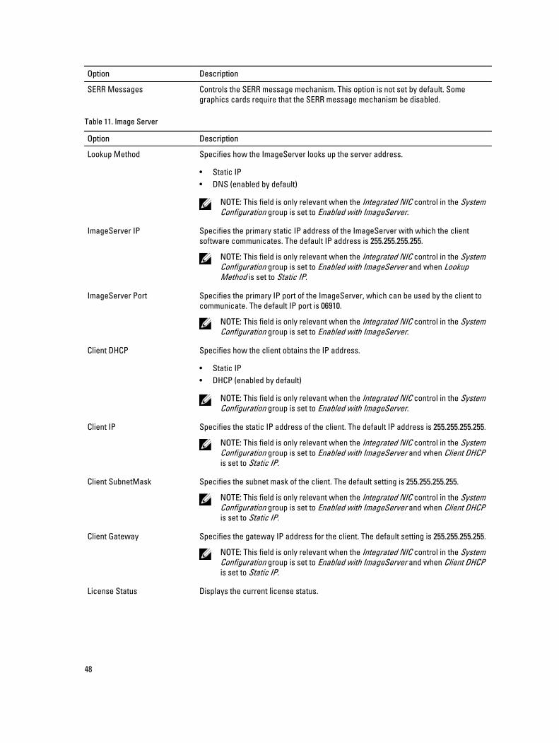
Table 11. Image Server
Option Description
Lookup Method Specifies how the ImageServer looks up the server address.
• Static IP• DNS (enabled by default)
NOTE: This field is only relevant when the Integrated NIC control in the System Configuration group is set to Enabled with ImageServer.
ImageServer IP Specifies the primary static IP address of the ImageServer with which the client software communicates. The default IP address is 255.255.255.255.
NOTE: This field is only relevant when the Integrated NIC control in the System Configuration group is set to Enabled with ImageServer and when Lookup Method is set to Static IP.
ImageServer Port Specifies the primary IP port of the ImageServer, which can be used by the client to communicate. The default IP port is 06910.
NOTE: This field is only relevant when the Integrated NIC control in the System Configuration group is set to Enabled with ImageServer.
Client DHCP Specifies how the client obtains the IP address.
• Static IP• DHCP (enabled by default)
NOTE: This field is only relevant when the Integrated NIC control in the System Configuration group is set to Enabled with ImageServer.
Client IP Specifies the static IP address of the client. The default IP address is 255.255.255.255.
NOTE: This field is only relevant when the Integrated NIC control in the System Configuration group is set to Enabled with ImageServer and when Client DHCP is set to Static IP.
Client SubnetMask Specifies the subnet mask of the client. The default setting is 255.255.255.255.
NOTE: This field is only relevant when the Integrated NIC control in the System Configuration group is set to Enabled with ImageServer and when Client DHCP is set to Static IP.
Client Gateway Specifies the gateway IP address for the client. The default setting is 255.255.255.255.
NOTE: This field is only relevant when the Integrated NIC control in the System Configuration group is set to Enabled with ImageServer and when Client DHCP is set to Static IP.
License Status Displays the current license status.
48
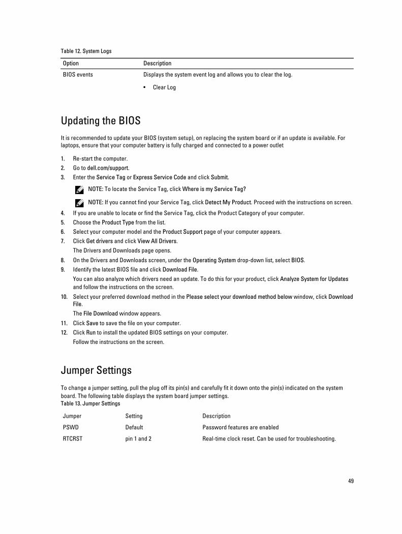
Table 12. System Logs
Option Description
BIOS events Displays the system event log and allows you to clear the log.
• Clear Log
Updating the BIOS It is recommended to update your BIOS (system setup), on replacing the system board or if an update is available. For laptops, ensure that your computer battery is fully charged and connected to a power outlet
1. Re-start the computer.2. Go to dell.com/support.3. Enter the Service Tag or Express Service Code and click Submit.
NOTE: To locate the Service Tag, click Where is my Service Tag?
NOTE: If you cannot find your Service Tag, click Detect My Product. Proceed with the instructions on screen.
4. If you are unable to locate or find the Service Tag, click the Product Category of your computer.5. Choose the Product Type from the list.6. Select your computer model and the Product Support page of your computer appears.7. Click Get drivers and click View All Drivers.
The Drivers and Downloads page opens.
8. On the Drivers and Downloads screen, under the Operating System drop-down list, select BIOS.9. Identify the latest BIOS file and click Download File.
You can also analyze which drivers need an update. To do this for your product, click Analyze System for Updates and follow the instructions on the screen.
10. Select your preferred download method in the Please select your download method below window, click Download File.The File Download window appears.
11. Click Save to save the file on your computer.12. Click Run to install the updated BIOS settings on your computer.
Follow the instructions on the screen.
Jumper SettingsTo change a jumper setting, pull the plug off its pin(s) and carefully fit it down onto the pin(s) indicated on the system board. The following table displays the system board jumper settings.Table 13. Jumper Settings
Jumper Setting Description
PSWD Default Password features are enabled
RTCRST pin 1 and 2 Real-time clock reset. Can be used for troubleshooting.
49
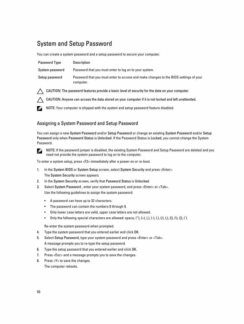
System and Setup PasswordYou can create a system password and a setup password to secure your computer.
Password Type Description
System password Password that you must enter to log on to your system.
Setup password Password that you must enter to access and make changes to the BIOS settings of your computer.
CAUTION: The password features provide a basic level of security for the data on your computer.
CAUTION: Anyone can access the data stored on your computer if it is not locked and left unattended.
NOTE: Your computer is shipped with the system and setup password feature disabled.
Assigning a System Password and Setup Password
You can assign a new System Password and/or Setup Password or change an existing System Password and/or Setup Password only when Password Status is Unlocked. If the Password Status is Locked, you cannot change the System Password.
NOTE: If the password jumper is disabled, the existing System Password and Setup Password are deleted and you need not provide the system password to log on to the computer.
To enter a system setup, press <F2> immediately after a power-on or re-boot.
1. In the System BIOS or System Setup screen, select System Security and press <Enter>.The System Security screen appears.
2. In the System Security screen, verify that Password Status is Unlocked.3. Select System Password , enter your system password, and press <Enter> or <Tab>.
Use the following guidelines to assign the system password:
• A password can have up to 32 characters.
• The password can contain the numbers 0 through 9.
• Only lower case letters are valid, upper case letters are not allowed.
• Only the following special characters are allowed: space, (”), (+), (,), (-), (.), (/), (;), ([), (\), (]), (`).
Re-enter the system password when prompted.
4. Type the system password that you entered earlier and click OK.5. Select Setup Password, type your system password and press <Enter> or <Tab>.
A message prompts you to re-type the setup password.
6. Type the setup password that you entered earlier and click OK.7. Press <Esc> and a message prompts you to save the changes.8. Press <Y> to save the changes.
The computer reboots.
50
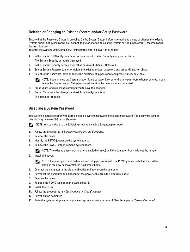
Deleting or Changing an Existing System and/or Setup Password
Ensure that the Password Status is Unlocked (in the System Setup) before attempting to delete or change the existing System and/or Setup password. You cannot delete or change an existing System or Setup password, if the Password Status is Locked.To enter the System Setup, press <F2> immediately after a power-on or reboot.
1. In the System BIOS or System Setup screen, select System Security and press <Enter>.The System Security screen is displayed.
2. In the System Security screen, verify that Password Status is Unlocked.3. Select System Password, alter or delete the existing system password and press <Enter> or <Tab>.4. Select Setup Password, alter or delete the existing setup password and press <Enter> or <Tab>.
NOTE: If you change the System and/or Setup password, re-enter the new password when promoted. If you delete the System and/or Setup password, confirm the deletion when promoted.
5. Press <Esc> and a message prompts you to save the changes.6. Press <Y> to save the changes and exit from the System Setup.
The computer reboots.
Disabling a System Password
The system's software security features include a system password and a setup password. The password jumper disables any password(s) currently in use.
NOTE: You can also use the following steps to disable a forgotten password.
1. Follow the procedures in Before Working on Your Computer.2. Remove the cover.3. Identify the PSWD jumper on the system board.4. Remove the PSWD jumper from the system board.
NOTE: The existing passwords are not disabled (erased) until the computer boots without the jumper.
5. Install the cover.
NOTE: If you assign a new system and/or setup password with the PSWD jumper installed, the system disables the new password(s) the next time it boots.
6. Connect the computer to the electrical outlet and power-on the computer.7. Power-off the computer and disconnect the power cable from the electrical outlet.8. Remove the cover.9. Replace the PSWD jumper on the system board.10. Install the cover.11. Follow the procedures in After Working on Your Computer.12. Power-on the computer.13. Go to the system setup, and assign a new system or setup password. See Setting up a System Password.
51
4DiagnosticsIf you experience a problem with your computer, run the ePSA diagnostics before contacting Dell for technical assistance. The purpose of running diagnostics is to test your computer's hardware without requiring additional equipment or risking data loss. If you are unable to fix the problem yourself, service and support personnel can use the diagnostics results to help you solve the problem.
Enhanced Pre-Boot System Assessment (ePSA) DiagnosticsThe ePSA diagnostics (also known as system diagnostics) performs a complete check of your hardware. The ePSA is embedded with the BIOS and is launched by the BIOS internally. The embedded system diagnostics provides a set of options for particular devices or device groups allowing you to:
• Run tests automatically or in an interactive mode
• Repeat tests
• Display or save test results
• Run thorough tests to introduce additional test options to provide extra information about the failed device(s)
• View status messages that inform you if tests are completed successfully
• View error messages that inform you of problems encountered during testing
CAUTION: Use the system diagnostics to test only your computer. Using this program with other computers may cause invalid results or error messages.
NOTE: Some tests for specific devices require user interaction. Always ensure that you are present at the computer terminal when the diagnostic tests are performed.
1. Power-on the computer.2. As the computer boots, press the <F12> key as the Dell logo appears.3. On the boot menu screen, select the Diagnostics option.
The Enhanced Pre-boot System Assessment window is displayed, listing all devices detected in the computer. The diagnostics starts running the tests on all the detected devices.
4. If you wish to run a diagnostic test on a specific device, press <Esc> and click Yes to stop the diagnostic test.5. Select the device from the left pane and click Run Tests.6. If there are any issues, error codes are displayed.
Note the error code and contact Dell.
52
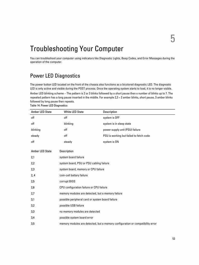
5Troubleshooting Your ComputerYou can troubleshoot your computer using indicators like Diagnostic Lights, Beep Codes, and Error Messages during the operation of the computer.
Power LED DiagnosticsThe power button LED located on the front of the chassis also functions as a bicolored diagnostic LED. The diagnostic LED is only active and visible during the POST process. Once the operating system starts to load, it is no longer visible.
Amber LED blinking scheme – The pattern is 2 or 3 blinks followed by a short pause then x number of blinks up to 7. The repeated pattern has a long pause inserted in the middle. For example 2,3 = 2 amber blinks, short pause, 3 amber blinks followed by long pause then repeats.Table 14. Power LED Diagnostics
Amber LED State White LED State Description
off off system is OFF
off blinking system is in sleep state
blinking off power supply unit (PSU) failure
steady off PSU is working but failed to fetch code
off steady system is ON
Amber LED State Description
2,1 system board failure
2,2 system board, PSU or PSU cabling failure
2,3 system board, memory or CPU failure
2, 4 coin-cell battery failure
2,5 corrupt BIOS
2,6 CPU configuration failure or CPU failure
2,7 memory modules are detected, but a memory failure
3,1 possible peripheral card or system board failure
3,2 possible USB failure
3,3 no memory modules are detected
3,4 possible system board error
3,5 memory modules are detected, but a memory configuration or compatibility error
53
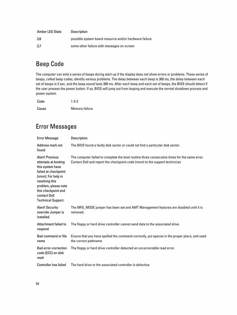
Amber LED State Description
3,6 possible system board resource and/or hardware failure
3,7 some other failure with messages on screen
Beep CodeThe computer can emit a series of beeps during start-up if the display does not show errors or problems. These series of beeps, called beep codes, identify various problems. The delay between each beep is 300 ms, the delay between each set of beeps is 3 sec, and the beep sound lasts 300 ms. After each beep and each set of beeps, the BIOS should detect if the user presses the power button. If so, BIOS will jump out from looping and execute the normal shutdown process and power system.
Code 1-3-2
Cause Memory failure
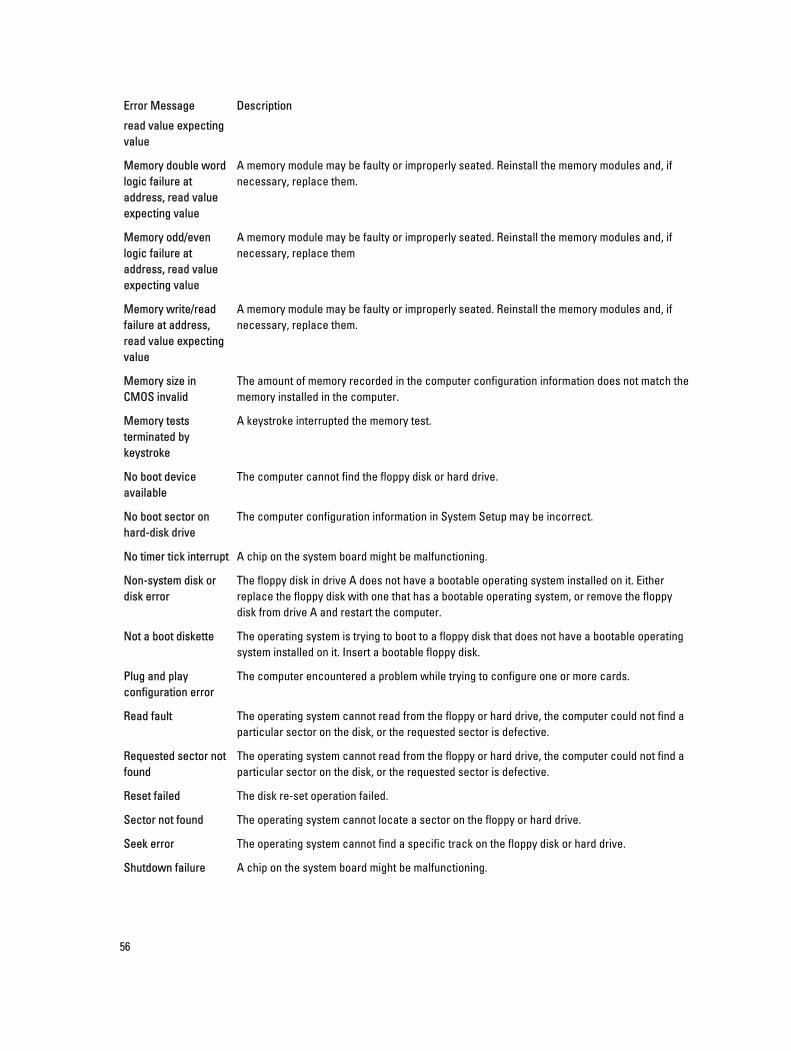
Error Messages
Error Message Description
Address mark not found
The BIOS found a faulty disk sector or could not find a particular disk sector.
Alert! Previous attempts at booting this system have failed at checkpoint [nnnn]. For help in resolving this problem, please note this checkpoint and contact Dell Technical Support.
The computer failed to complete the boot routine three consecutive times for the same error. Contact Dell and report the checkpoint code (nnnn) to the support technician
Alert! Security override Jumper is installed.
The MFG_MODE jumper has been set and AMT Management features are disabled until it is removed.
Attachment failed to respond
The floppy or hard drive controller cannot send data to the associated drive.
Bad command or file name
Ensure that you have spelled the command correctly, put spaces in the proper place, and used the correct pathname.
Bad error-correction code (ECC) on disk read
The floppy or hard drive controller detected an uncorrectable read error.
Controller has failed The hard drive or the associated controller is defective.
54
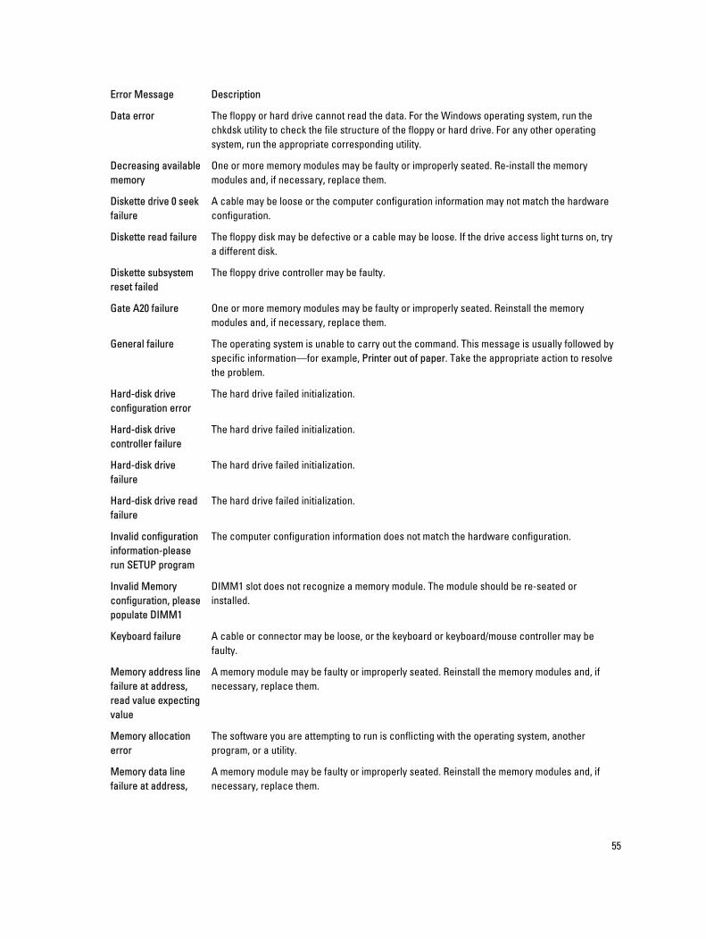
Error Message Description
Data error The floppy or hard drive cannot read the data. For the Windows operating system, run the chkdsk utility to check the file structure of the floppy or hard drive. For any other operating system, run the appropriate corresponding utility.
Decreasing available memory
One or more memory modules may be faulty or improperly seated. Re-install the memory modules and, if necessary, replace them.
Diskette drive 0 seek failure
A cable may be loose or the computer configuration information may not match the hardware configuration.
Diskette read failure The floppy disk may be defective or a cable may be loose. If the drive access light turns on, try a different disk.
Diskette subsystem reset failed
The floppy drive controller may be faulty.
Gate A20 failure One or more memory modules may be faulty or improperly seated. Reinstall the memory modules and, if necessary, replace them.
General failure The operating system is unable to carry out the command. This message is usually followed by specific information—for example, Printer out of paper. Take the appropriate action to resolve the problem.
Hard-disk drive configuration error
The hard drive failed initialization.
Hard-disk drive controller failure
The hard drive failed initialization.
Hard-disk drive failure
The hard drive failed initialization.
Hard-disk drive read failure
The hard drive failed initialization.
Invalid configuration information-please run SETUP program
The computer configuration information does not match the hardware configuration.
Invalid Memory configuration, please populate DIMM1
DIMM1 slot does not recognize a memory module. The module should be re-seated or installed.
Keyboard failure A cable or connector may be loose, or the keyboard or keyboard/mouse controller may be faulty.
Memory address line failure at address, read value expecting value
A memory module may be faulty or improperly seated. Reinstall the memory modules and, if necessary, replace them.
Memory allocation error
The software you are attempting to run is conflicting with the operating system, another program, or a utility.
Memory data line failure at address,
A memory module may be faulty or improperly seated. Reinstall the memory modules and, if necessary, replace them.
55
Error Message Description
read value expecting value
Memory double word logic failure at address, read value expecting value
A memory module may be faulty or improperly seated. Reinstall the memory modules and, if necessary, replace them.
Memory odd/even logic failure at address, read value expecting value
A memory module may be faulty or improperly seated. Reinstall the memory modules and, if necessary, replace them
Memory write/read failure at address, read value expecting value
A memory module may be faulty or improperly seated. Reinstall the memory modules and, if necessary, replace them.
Memory size in CMOS invalid
The amount of memory recorded in the computer configuration information does not match the memory installed in the computer.
Memory tests terminated by keystroke
A keystroke interrupted the memory test.
No boot device available
The computer cannot find the floppy disk or hard drive.
No boot sector on hard-disk drive
The computer configuration information in System Setup may be incorrect.
No timer tick interrupt A chip on the system board might be malfunctioning.
Non-system disk or disk error
The floppy disk in drive A does not have a bootable operating system installed on it. Either replace the floppy disk with one that has a bootable operating system, or remove the floppy disk from drive A and restart the computer.
Not a boot diskette The operating system is trying to boot to a floppy disk that does not have a bootable operating system installed on it. Insert a bootable floppy disk.
Plug and play configuration error
The computer encountered a problem while trying to configure one or more cards.
Read fault The operating system cannot read from the floppy or hard drive, the computer could not find a particular sector on the disk, or the requested sector is defective.
Requested sector not found
The operating system cannot read from the floppy or hard drive, the computer could not find a particular sector on the disk, or the requested sector is defective.
Reset failed The disk re-set operation failed.
Sector not found The operating system cannot locate a sector on the floppy or hard drive.
Seek error The operating system cannot find a specific track on the floppy disk or hard drive.
Shutdown failure A chip on the system board might be malfunctioning.
56

Error Message Description
Time-of-day clock stopped
The battery might be dead.
Time-of-day not set-please run the System Setup program
The time or date stored in System Setup does not match the computer clock.
Timer chip counter 2 failed
A chip on the system board may be malfunctioning.
Unexpected interrupt in protected mode
The keyboard controller may be malfunctioning or a memory module may be loose.
WARNING: Dell's Disk Monitoring System has detected that drive [0/1] on the [primary/secondary] EIDE controller is operating outside of normal specifications. It is advisable to immediately back up your data and replace your hard drive by calling your support desk or Dell.
During initial startup, the drive detected possible error conditions. When your computer finishes booting, immediately back up your data and replace your hard drive (for installation procedures, see "Adding and Removing Parts" for your computer type). If no replacement drive is immediately available and the drive is not the only bootable drive, enter System Setup and change the appropriate drive setting to None. Then remove the drive from the computer.
Write fault The operating system cannot write to the floppy or hard drive.
Write fault on selected drive
The operating system cannot write to the floppy or hard drive.
57
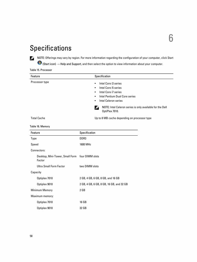
6Specifications
NOTE: Offerings may vary by region. For more information regarding the configuration of your computer, click Start
(Start icon) → Help and Support, and then select the option to view information about your computer.
Table 15. Processor
Feature Specification
Processor type • Intel Core i3 series• Intel Core i5 series• Intel Core i7 series• Intel Pentium Dual Core series• Intel Celeron series
NOTE: Intel Celeron series is only available for the Dell OptiPlex 7010.
Total Cache Up to 8 MB cache depending on processor type
Table 16. Memory
Feature Specification
Type DDR3
Speed 1600 MHz
Connectors:
Desktop, Mini-Tower, Small Form Factor
four DIMM slots
Ultra Small Form Factor two DIMM slots
Capacity
Optiplex 7010 2 GB, 4 GB, 6 GB, 8 GB, and 16 GB
Optiplex 9010 2 GB, 4 GB, 6 GB, 8 GB, 16 GB, and 32 GB
Minimum Memory 2 GB
Maximum memory:
Optiplex 7010 16 GB
Optiplex 9010 32 GB
58
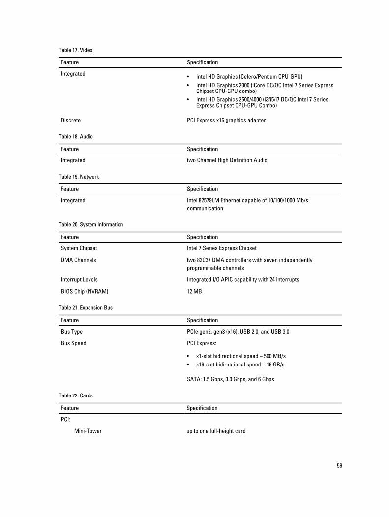
Table 17. Video
Feature Specification
Integrated • Intel HD Graphics (Celero/Pentium CPU-GPU)• Intel HD Graphics 2000 (iCore DC/QC Intel 7 Series Express
Chipset CPU-GPU combo)• Intel HD Graphics 2500/4000 (i3/i5/i7 DC/QC Intel 7 Series
Express Chipset CPU-GPU Combo)
Discrete PCI Express x16 graphics adapter
Table 18. Audio
Feature Specification
Integrated two Channel High Definition Audio
Table 19. Network
Feature Specification
Integrated Intel 82579LM Ethernet capable of 10/100/1000 Mb/s communication
Table 20. System Information
Feature Specification
System Chipset Intel 7 Series Express Chipset
DMA Channels two 82C37 DMA controllers with seven independently programmable channels
Interrupt Levels Integrated I/O APIC capability with 24 interrupts
BIOS Chip (NVRAM) 12 MB
Table 21. Expansion Bus
Feature Specification
Bus Type PCIe gen2, gen3 (x16), USB 2.0, and USB 3.0
Bus Speed PCI Express:
• x1-slot bidirectional speed – 500 MB/s• x16-slot bidirectional speed – 16 GB/s
SATA: 1.5 Gbps, 3.0 Gbps, and 6 Gbps
Table 22. Cards
Feature Specification
PCI:
Mini-Tower up to one full-height card
59
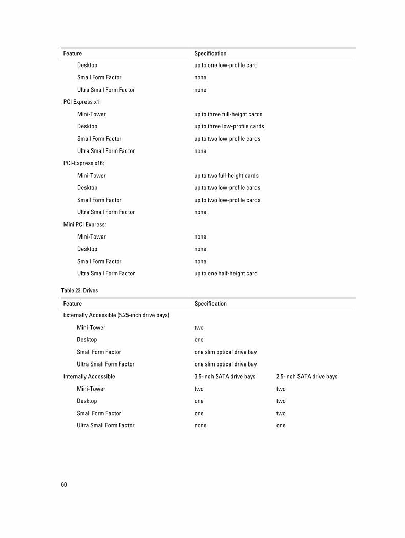
Feature Specification
Desktop up to one low-profile card
Small Form Factor none
Ultra Small Form Factor none
PCI Express x1:
Mini-Tower up to three full-height cards
Desktop up to three low-profile cards
Small Form Factor up to two low-profile cards
Ultra Small Form Factor none
PCI-Express x16:
Mini-Tower up to two full-height cards
Desktop up to two low-profile cards
Small Form Factor up to two low-profile cards
Ultra Small Form Factor none
Mini PCI Express:
Mini-Tower none
Desktop none
Small Form Factor none
Ultra Small Form Factor up to one half-height card
Table 23. Drives
Feature Specification
Externally Accessible (5.25-inch drive bays)
Mini-Tower two
Desktop one
Small Form Factor one slim optical drive bay
Ultra Small Form Factor one slim optical drive bay
Internally Accessible 3.5-inch SATA drive bays 2.5-inch SATA drive bays
Mini-Tower two two
Desktop one two
Small Form Factor one two
Ultra Small Form Factor none one
60
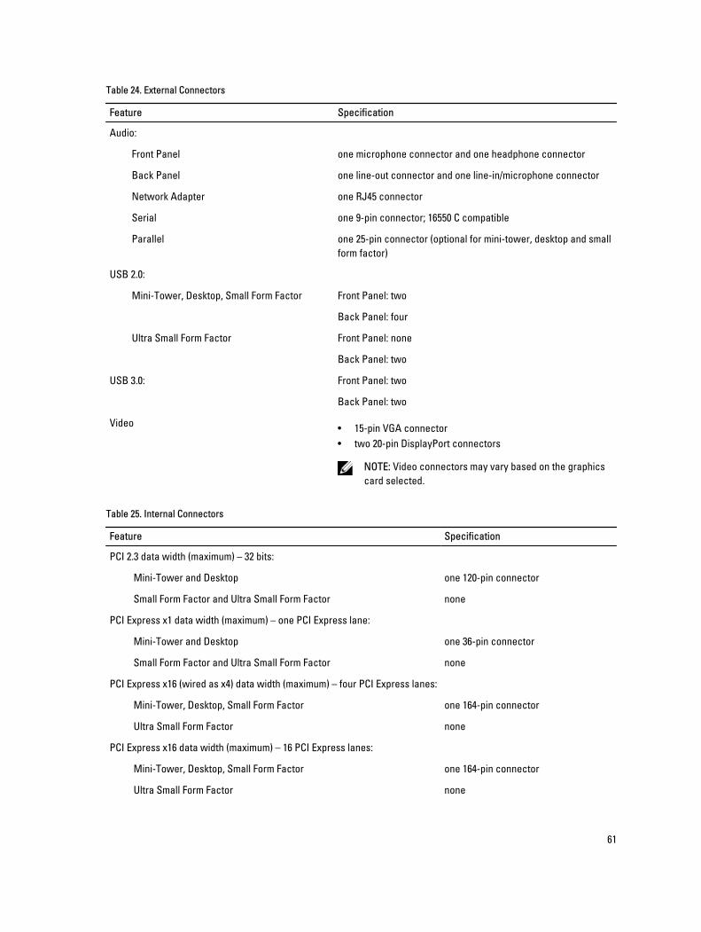
Table 24. External Connectors
Feature Specification
Audio:
Front Panel one microphone connector and one headphone connector
Back Panel one line-out connector and one line-in/microphone connector
Network Adapter one RJ45 connector
Serial one 9-pin connector; 16550 C compatible
Parallel one 25-pin connector (optional for mini-tower, desktop and small form factor)
USB 2.0:
Mini-Tower, Desktop, Small Form Factor Front Panel: two
Back Panel: four
Ultra Small Form Factor Front Panel: none
Back Panel: two
USB 3.0: Front Panel: two
Back Panel: two
Video • 15-pin VGA connector• two 20-pin DisplayPort connectors
NOTE: Video connectors may vary based on the graphics card selected.
Table 25. Internal Connectors
Feature Specification
PCI 2.3 data width (maximum) – 32 bits:
Mini-Tower and Desktop one 120-pin connector
Small Form Factor and Ultra Small Form Factor none
PCI Express x1 data width (maximum) – one PCI Express lane:
Mini-Tower and Desktop one 36-pin connector
Small Form Factor and Ultra Small Form Factor none
PCI Express x16 (wired as x4) data width (maximum) – four PCI Express lanes:
Mini-Tower, Desktop, Small Form Factor one 164-pin connector
Ultra Small Form Factor none
PCI Express x16 data width (maximum) – 16 PCI Express lanes:
Mini-Tower, Desktop, Small Form Factor one 164-pin connector
Ultra Small Form Factor none
61
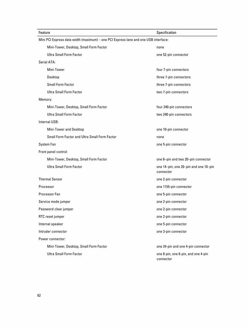
Feature Specification
Mini PCI Express data width (maximum) – one PCI Express lane and one USB interface:
Mini-Tower, Desktop, Small Form Factor none
Ultra Small Form Factor one 52-pin connector
Serial ATA:
Mini-Tower four 7-pin connectors
Desktop three 7-pin connectors
Small Form Factor three 7-pin connectors
Ultra Small Form Factor two 7-pin connectors
Memory:
Mini-Tower, Desktop, Small Form Factor four 240-pin connectors
Ultra Small Form Factor two 240-pin connectors
Internal USB:
Mini-Tower and Desktop one 10-pin connector
Small Form Factor and Ultra Small Form Factor none
System Fan one 5-pin connector
Front panel control:
Mini-Tower, Desktop, Small Form Factor one 6–pin and two 20–pin connector
Ultra Small Form Factor one 14–pin, one 20–pin and one 10–pin connector
Thermal Sensor one 2-pin connector
Processor one 1155-pin connector
Processor Fan one 5-pin connector
Service mode jumper one 2-pin connector
Password clear jumper one 2-pin connector
RTC reset jumper one 2-pin connector
Internal speaker one 5-pin connector
Intruder connector one 3-pin connector
Power connector:
Mini-Tower, Desktop, Small Form Factor one 24-pin and one 4-pin connector
Ultra Small Form Factor one 8-pin, one 6-pin, and one 4-pin connector
62
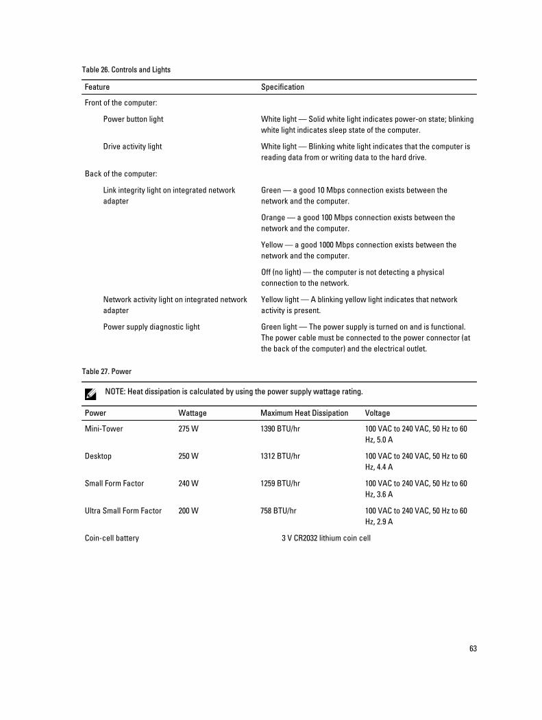
Table 26. Controls and Lights
Feature Specification
Front of the computer:
Power button light White light — Solid white light indicates power-on state; blinking white light indicates sleep state of the computer.
Drive activity light White light — Blinking white light indicates that the computer is reading data from or writing data to the hard drive.
Back of the computer:
Link integrity light on integrated network adapter
Green — a good 10 Mbps connection exists between the network and the computer.
Orange — a good 100 Mbps connection exists between the network and the computer.
Yellow — a good 1000 Mbps connection exists between the network and the computer.
Off (no light) — the computer is not detecting a physical connection to the network.
Network activity light on integrated network adapter
Yellow light — A blinking yellow light indicates that network activity is present.
Power supply diagnostic light Green light — The power supply is turned on and is functional. The power cable must be connected to the power connector (at the back of the computer) and the electrical outlet.
Table 27. Power
NOTE: Heat dissipation is calculated by using the power supply wattage rating.
Power Wattage Maximum Heat Dissipation Voltage
Mini-Tower 275 W 1390 BTU/hr 100 VAC to 240 VAC, 50 Hz to 60 Hz, 5.0 A
Desktop 250 W 1312 BTU/hr 100 VAC to 240 VAC, 50 Hz to 60 Hz, 4.4 A
Small Form Factor 240 W 1259 BTU/hr 100 VAC to 240 VAC, 50 Hz to 60 Hz, 3.6 A
Ultra Small Form Factor 200 W 758 BTU/hr 100 VAC to 240 VAC, 50 Hz to 60 Hz, 2.9 A
Coin-cell battery 3 V CR2032 lithium coin cell
63
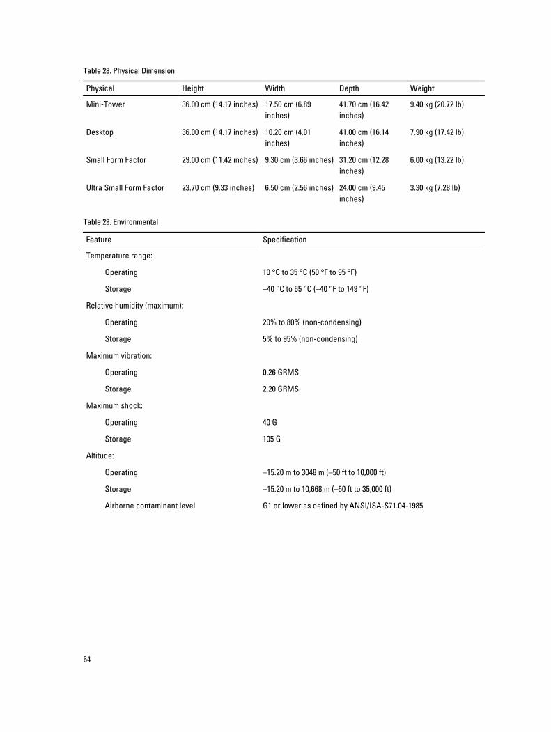
Table 28. Physical Dimension
Physical Height Width Depth Weight
Mini-Tower 36.00 cm (14.17 inches) 17.50 cm (6.89 inches)
41.70 cm (16.42 inches)
9.40 kg (20.72 lb)
Desktop 36.00 cm (14.17 inches) 10.20 cm (4.01 inches)
41.00 cm (16.14 inches)
7.90 kg (17.42 lb)
Small Form Factor 29.00 cm (11.42 inches) 9.30 cm (3.66 inches) 31.20 cm (12.28 inches)
6.00 kg (13.22 lb)
Ultra Small Form Factor 23.70 cm (9.33 inches) 6.50 cm (2.56 inches) 24.00 cm (9.45 inches)
3.30 kg (7.28 lb)
Table 29. Environmental
Feature Specification
Temperature range:
Operating 10 °C to 35 °C (50 °F to 95 °F)
Storage –40 °C to 65 °C (–40 °F to 149 °F)
Relative humidity (maximum):
Operating 20% to 80% (non-condensing)
Storage 5% to 95% (non-condensing)
Maximum vibration:
Operating 0.26 GRMS
Storage 2.20 GRMS
Maximum shock:
Operating 40 G
Storage 105 G
Altitude:
Operating –15.20 m to 3048 m (–50 ft to 10,000 ft)
Storage –15.20 m to 10,668 m (–50 ft to 35,000 ft)
Airborne contaminant level G1 or lower as defined by ANSI/ISA-S71.04-1985
64

7Contacting Dell To contact Dell for sales, technical support, or customer service issues:
1. Visit support.dell.com.
2. Verify your country or region in the Choose a Country/Region drop-down menu at the bottom of the page.
3. Click Contact Us on the left side of the page.
4. Select the appropriate service or support link based on your need.
5. Choose the method of contacting Dell that is convenient for you.
65