Embed Size (px)
Citation preview

Dell OptiPlex 7070 Ultra Service Manual
Regulatory Model: D13URegulatory Type: D13U001

Notes, cautions, and warnings
NOTE: A NOTE indicates important information that helps you make better use of your product.
CAUTION: A CAUTION indicates either potential damage to hardware or loss of data and tells you how to avoid the
problem.
WARNING: A WARNING indicates a potential for property damage, personal injury, or death.
© 2019 Dell Inc. or its subsidiaries. All rights reserved. Dell, EMC, and other trademarks are trademarks of Dell Inc. or its subsidiaries. Other trademarks may be trademarks of their respective owners.
2019 - 09
Rev. A00

1 Working on your computer............................................................................................................ 5Safety instructions................................................................................................................................................................ 5Turning off your computer — Windows 10....................................................................................................................... 5Before working inside your device.......................................................................................................................................6After working inside your device......................................................................................................................................... 6
2 Removing and installing components............................................................................................. 8Recommended tools..............................................................................................................................................................8Screw List...............................................................................................................................................................................8Hard-drive assembly..............................................................................................................................................................8
Removing the hard-drive assembly............................................................................................................................... 8Installing the hard-drive assembly................................................................................................................................. 9
Hard-drive bracket................................................................................................................................................................11Removing the hard-drive bracket................................................................................................................................. 11Installing the hard-drive bracket....................................................................................................................................11
Hard drive..............................................................................................................................................................................12Removing the hard drive............................................................................................................................................... 12Installing the hard drive..................................................................................................................................................13
Cover..................................................................................................................................................................................... 14Removing the cover.......................................................................................................................................................14Installing the cover......................................................................................................................................................... 15
Memory modules..................................................................................................................................................................16Removing the memory module.....................................................................................................................................16Installing the memory module....................................................................................................................................... 17
WLAN card............................................................................................................................................................................18Removing the WLAN card............................................................................................................................................ 18Installing the WLAN card...............................................................................................................................................19
Solid state drive................................................................................................................................................................... 20Removing the solid-state drive....................................................................................................................................20Installing the solid-state drive....................................................................................................................................... 21
System fan........................................................................................................................................................................... 22Removing the system fan.............................................................................................................................................22Installing the system fan............................................................................................................................................... 22
Power button....................................................................................................................................................................... 23Removing the power button........................................................................................................................................ 23Installing the power button...........................................................................................................................................24
Coin-cell battery.................................................................................................................................................................. 26Removing the coin-cell battery....................................................................................................................................26Installing the coin-cell battery...................................................................................................................................... 27
System board.......................................................................................................................................................................28Removing the system board........................................................................................................................................ 28Installing the system board...........................................................................................................................................29
Heat-sink............................................................................................................................................................................... 31Removing the heat-sink.................................................................................................................................................31
Contents
Contents 3

Installing the heat-sink.................................................................................................................................................. 32Replacing the chassis..........................................................................................................................................................34
3 System setup.............................................................................................................................35Boot menu............................................................................................................................................................................35Navigation keys....................................................................................................................................................................35Boot Sequence.................................................................................................................................................................... 36System setup options......................................................................................................................................................... 36
General options.............................................................................................................................................................. 36System information........................................................................................................................................................37Video................................................................................................................................................................................38Security...........................................................................................................................................................................38Secure boot....................................................................................................................................................................39Intel Software Guard Extensions.................................................................................................................................40Performance...................................................................................................................................................................40Power management.......................................................................................................................................................41POST behavior...............................................................................................................................................................42Manageability................................................................................................................................................................. 42Virtualization support.................................................................................................................................................... 42Wireless...........................................................................................................................................................................43Maintenance screen...................................................................................................................................................... 43System logs.................................................................................................................................................................... 44Advanced Configuration............................................................................................................................................... 44
Updating the BIOS in Windows ........................................................................................................................................ 44Updating BIOS on systems with BitLocker enabled................................................................................................. 45Updating your BIOS from the F12 One-Time Boot Menu........................................................................................ 45Updating your system BIOS using a USB flash drive................................................................................................45
System and setup password..............................................................................................................................................46Assigning a system setup password........................................................................................................................... 46Deleting or changing an existing system setup password........................................................................................46
4 Troubleshooting......................................................................................................................... 48Enhanced Pre-Boot System Assessment (ePSA) diagnostics......................................................................................48
Running the ePSA diagnostics.....................................................................................................................................48WiFi power cycle................................................................................................................................................................. 48Diagnostic LED.....................................................................................................................................................................49
5 Getting help............................................................................................................................... 51Contacting Dell..................................................................................................................................................................... 51
4 Contents

Working on your computer
Safety instructionsPrerequisites
Use the following safety guidelines to protect your computer from potential damage and to ensure your personal safety. Unless otherwise noted, each procedure included in this document assumes that the following conditions exist:
• You have read the safety information that shipped with your computer.• A component can be replaced or, if purchased separately, installed by performing the removal procedure in reverse order.
About this task
NOTE: Disconnect all power sources before opening the computer cover or panels. After you finish working inside the
computer, replace all covers, panels, and screws before connecting to the power source.
WARNING: Before working inside your computer, read the safety information that shipped with your computer. For
additional safety best practices information, see the Regulatory Compliance Homepage
CAUTION: Many repairs may only be done by a certified service technician. You should only perform troubleshooting and
simple repairs as authorized in your product documentation, or as directed by the online or telephone service and
support team. Damage due to servicing that is not authorized by Dell is not covered by your warranty. Read and follow
the safety instructions that came with the product.
CAUTION: To avoid electrostatic discharge, ground yourself by using a wrist grounding strap or by periodically touching
an unpainted metal surface at the same time as touching a connector on the back of the computer.
CAUTION: Handle components and cards with care. Do not touch the components or contacts on a card. Hold a card by
its edges or by its metal mounting bracket. Hold a component such as a processor by its edges, not by its pins.
CAUTION: When you disconnect a cable, pull on its connector or on its pull-tab, not on the cable itself. Some cables
have connectors with locking tabs; if you are disconnecting this type of cable, press in on the locking tabs before you
disconnect the cable. As you pull connectors apart, keep them evenly aligned to avoid bending any connector pins. Also,
before you connect a cable, ensure that both connectors are correctly oriented and aligned.
NOTE: The color of your computer and certain components may appear differently than shown in this document.
CAUTION: System will shut down if side covers are removed while the system is running. The system will not power on
if the side cover is removed.
CAUTION: System will shut down if side covers are removed while the system is running. The system will not power on
if the side cover is removed.
CAUTION: System will shut down if side covers are removed while the system is running. The system will not power on
if the side cover is removed.
Turning off your computer — Windows 10About this task
CAUTION: To avoid losing data, save and close all open files and exit all open programs before you turn off your
computer or remove the side cover.
1
Working on your computer 5

Steps
1. Click or tap .
2. Click or tap and then click or tap Shut down.
NOTE: Ensure that the computer and all attached devices are turned off. If your computer and attached devices did
not automatically turn off when you shut down your operating system, press and hold the power button for about 6
seconds to turn them off.
Before working inside your deviceAbout this task
To avoid damaging your device, perform the following steps before you begin working inside the device:
Steps
1. Ensure that you follow the Safety Instruction.
2. Ensure that your work surface is flat and clean to prevent the device cover from being scratched.
3. Turn off your device.
4. Remove the device from the stand:
Removing device from Fixed-height stand or Height-adjustable stand:
a) Disconnect the keyboard/mouse, network, power adapter, and USB Type-C cable from the device.
CAUTION: To disconnect a network cable, first unplug the cable from your device and then unplug the cable from
the network device.
b) Slide the release latch on the stand until you hear a click to release the stand cover.c) Slide and lift the back cover to release it from the stand.d) Pull the retention latch that secures the device to the stand cover.e) Lift the device from the cover.
Removing device from offset VESA mount:
a) Disconnect the keyboard/mouse, network, power adapter, and USB Type-C cable from the device.b) Push the quick release button on the VESA mount.c) Slide and remove the monitor arm from the offset VESA mount (U/P-series monitor).
NOTE: For E-series monitor, remove the VESA cover.
d) Remove the four screws that secure the offset VESA mount to the monitor.e) Remove the four holders on which the offset VESA mount is mounted.f) Lift the offset VESA mount from the monitor.g) Remove the four screws that secure the device to the offset VESA mount.h) Lift the device away from the offset VESA mount.
5. Press and hold the power button while the device is unplugged to ground the system board.
NOTE: To avoid electrostatic discharge, ground yourself by using a wrist grounding strap or by periodically touching
an unpainted metal surface at the same time as touching a connector on the back of the computer.
After working inside your deviceAbout this task
After you complete any replacement procedure, ensure that you connect any external devices, cards, and cables before turning on your computer.
Steps
1. Install the device in the stand:
Installing the device on Fixed-height stand or Height-adjustable stand:
6 Working on your computer

a) Unlock the latch on the lower chassis of the stand to remove the stand cover.b) Align and position the top side of the device to the upper chassis of the stand back cover.c) Align the power button on the device with the slot on the stand back cover chassis.d) Press the device until the retention latch clicks into place and secures it.e) Connect the keyboard/mouse, network, power adapter, and USB Type-C cable to the device.
CAUTION: To connect a network cable, first plug the cable into the network device and then plug it into the
device.
f) Slide the back cover, along with the device, into the stand until it clicks into place.g) Lock the stand cover.
Installing the device on offset VESA mount:
a) Align the screw holes on the device to the screw holes on the offset VESA mount.b) Install the four screws to secure the device to the offset VESA mount.c) Align the screw holes in the offset VESA mount with the screw holes on the back cover of the monitor.d) Install the four screws to secure the offset VESA mount to the monitor.e) Align the tabs on the adapter that is attached to the stand, with the slots on the back of the monitor.f) Slide the tabs on the stand adapter into its slots on the monitor.g) Connect the keyboard/mouse, network, power adapter, and USB Type-C cable to the device.
CAUTION: To connect a network cable, first plug the cable into the network device and then plug it into the
device.
2. Turn on your device.
3. If required, verify that the device works correctly by running ePSA diagnostics.
Working on your computer 7

Removing and installing components
Recommended toolsThe procedures in this document require the following tools:
• Phillips #0 screwdriver• Phillips #1 screwdriver• T6 Torx screwdriver• Plastic scribe
Screw ListThe following table shows the screw list and the images for different components.
Table 1. Screw Size List
Component Screw type Quantity Image
Power button M2x3 1
System board M2x3 4
HDD bracket (or non HDD bracket)
M2x3 1
M.2 WLAN M2x3.5 1
M.2 SSD M2x3.5 1
Hard-drive assembly
Removing the hard-drive assembly
Prerequisites
1. Follow the procedure in Before working inside your device.
About this task
The figure indicates the location of the hard-drive assembly module and provides a visual representation of the removal procedure.
2
8 Removing and installing components

Steps
1. Remove the M2x3 screw that secures the hard-drive assembly to the cover.
2. Turn the hard-drive assembly.
3. Lift the cable release latch and disconnect the hard-drive cable from the connector on the system board.
4. Carefully unroute the hard-drive cable from the slot on the chassis.
NOTE: Observe the routing of the hard-drive cable inside the chassis as you remove them. Route the cable properly
when you replace the component to prevent the cable from from being pinched or crimped.
5. Remove the hard-drive assembly.
Installing the hard-drive assembly
Prerequisites
If you are replacing a component, remove the existing component before performing the installation procedure.
About this task
The figure indicates the location of the hard-drive assembly module and provides a visual representation of the installation procedure.
Removing and installing components 9

Steps
1. Place the hard-drive assembly on the cover.
2. Route the hard-drive cable through the slot on the chassis.
3. Connect the hard-drive cable to the connector on the system board.
4. Route the hard-drive cable to the release latch.
5. Turn the hard-drive assembly module and align the tabs on the hard-drive assembly with the slots on the chassiis.
6. Align the screw hole on the hard-drive assembly module with the screw hole on the cover.
7. Replace the M2x3 screw to secure the hard-drive assembly module to the cover.
Next steps
1. Follow the procedure in After working on your device.
10 Removing and installing components

Hard-drive bracket
Removing the hard-drive bracket
Prerequisites
1. Follow the procedure in Before working inside your device.2. Remove the hard-drive assembly.
About this task
Steps
Pull the rubber tab on the protective sleeve and lift the hard-drive module out from the hard-drive bracket.
Installing the hard-drive bracket
Prerequisites
If you are replacing a component, remove the existing component before performing the installation procedure.
About this task
Steps
1. Align the connector edge of the hard-drive module with the tab end of the hard-drive bracket.
Removing and installing components 11

2. Place the hard-drive module in the hard-drive bracket.
Next steps
1. Install the hard drive assembly.2. Follow the procedure in After working on your device.
Hard drive
Removing the hard drive
Prerequisites
1. Follow the procedure in Before working inside your device.2. Remove the hard-drive assembly.3. Remove the hard-drive bracket.
About this task
The figure indicates the location of the hard-drive module and provides a visual representation of the removal procedure.
Steps
1. Disconnect the hard-drive cable from the connector on the hard drive.
2. Release the protective sleeve from one side of the hard-drive edges.
3. Gently pull the hard-drive out of the protective sleeve.
12 Removing and installing components

Installing the hard drive
Prerequisites
If you are replacing a component, remove the existing component before performing the installation procedure.
About this task
The figure indicates the location of the hard-drive module and provides a visual representation of the installation procedure.
Steps
1. Insert the hard drive into the protective sleeve.
NOTE: Ensure to match the mark on the protective sleeve with the hard drive PIN and connector location.
2. Pull the protective sleeves along the hard-drive edges.
3. Connect the hard-drive cable to the connector on the hard drive.
Next steps
1. Install the hard-drive bracket.2. Install the hard drive assembly.3. Follow the procedure in After working on your device.
Removing and installing components 13
Cover
Removing the cover
Prerequisites
1. Follow the procedure in Before working inside your device.
About this task
The figure indicates the location of the cover and provides a visual representation of the removal procedure.
Steps
1. Slide the cover to release it from the chassis.
2. Lift the cover.
14 Removing and installing components

Installing the cover
Prerequisites
If you are replacing a component, remove the existing component before performing the installation procedure.
About this task
The figure indicates the location of the cover and provides a visual representation of the installation procedure.
Steps
1. Align the tabs on the cover with the slots on the chassis.
2. Slide the cover until it clicks into place.
Next steps
1. Follow the procedure in After working on your device.
Removing and installing components 15

Memory modules
Removing the memory module
Prerequisites
1. Follow the procedure in Before working inside your device.2. Remove the cover.
About this task
The figure indicates the location of the memory module and provides a visual representation of the removal procedure.
Steps
1. Lift the absorber above the memory module.
2. Gently pry the retention clips away from the memory module until the memory module pops up.
3. Slide and remove the memory module from the memory-module slot on the system board.
16 Removing and installing components

Installing the memory module
Prerequisites
If you are replacing a component, remove the existing component before performing the installation procedure.
About this task
The figure indicates the location of the memory module and provides a visual representation of the installation procedure.
Steps
1. Lift the absorber above the memory-module slot.
2. Align the notch on the memory module with the tab on the memory-module slot.
3. Slide the memory module firmly into the slot at an angle.
4. Press the memory module down until it clicks into place.
NOTE: If you do not hear the click, remove the memory module and reinstall it.
5. Lower the absorber above the memory module.
Removing and installing components 17

Next steps
1. Install the cover.2. Follow the procedure in After working on your device.
WLAN card
Removing the WLAN card
Prerequisites
1. Follow the procedure in Before working inside your device.2. Remove the cover.
About this task
The figure indicates the location of the WLAN card and provides a visual representation of the removal procedure.
Steps
1. Remove the (M2x3.5) screw that secures the WLAN bracket to the system board.
2. Slide and lift the WLAN bracket.
18 Removing and installing components

3. Disconnect the WLAN antenna cables from the WLAN card.
4. Slide and remove the WLAN card from the WLAN connector on the system board.
Installing the WLAN card
Prerequisites
If you are replacing a component, remove the existing component before performing the installation procedure.
About this task
The figure indicates the location of the WLAN card and provides a visual representation of the installation procedure.
Steps
1. Connect the WLAN antenna cables to the WLAN card.
NOTE: Follow the indication on the WLAN card for the correct location of the antenna cables.
2. Align and place the WLAN card bracket to secure the WLAN antenna cables to the WLAN card.
3. Align the notch on the WLAN card with the WLAN connector and insert the WLAN card at an angle into the WLAN card slot.
4. Replace the (M2x3.5) screw to secure the WLAN card to the system board.
Removing and installing components 19

Next steps
1. Install the cover.2. Follow the procedure in After working on your device.
Solid state drive
Removing the solid-state drive
Prerequisites
1. Follow the procedure in Before working inside your device.2. Remove the cover.
About this task
The figure indicates the location of the M.2 2230 solid-state drive and provides a visual representation of the removal procedure.
20 Removing and installing components
Steps
1. Remove the (M2x3.5) screw that secures the solid-state module to the system board.
2. Slide the solid-state module out from the M.2 slot.
3. Peel the SSD thermal pad from the system board.
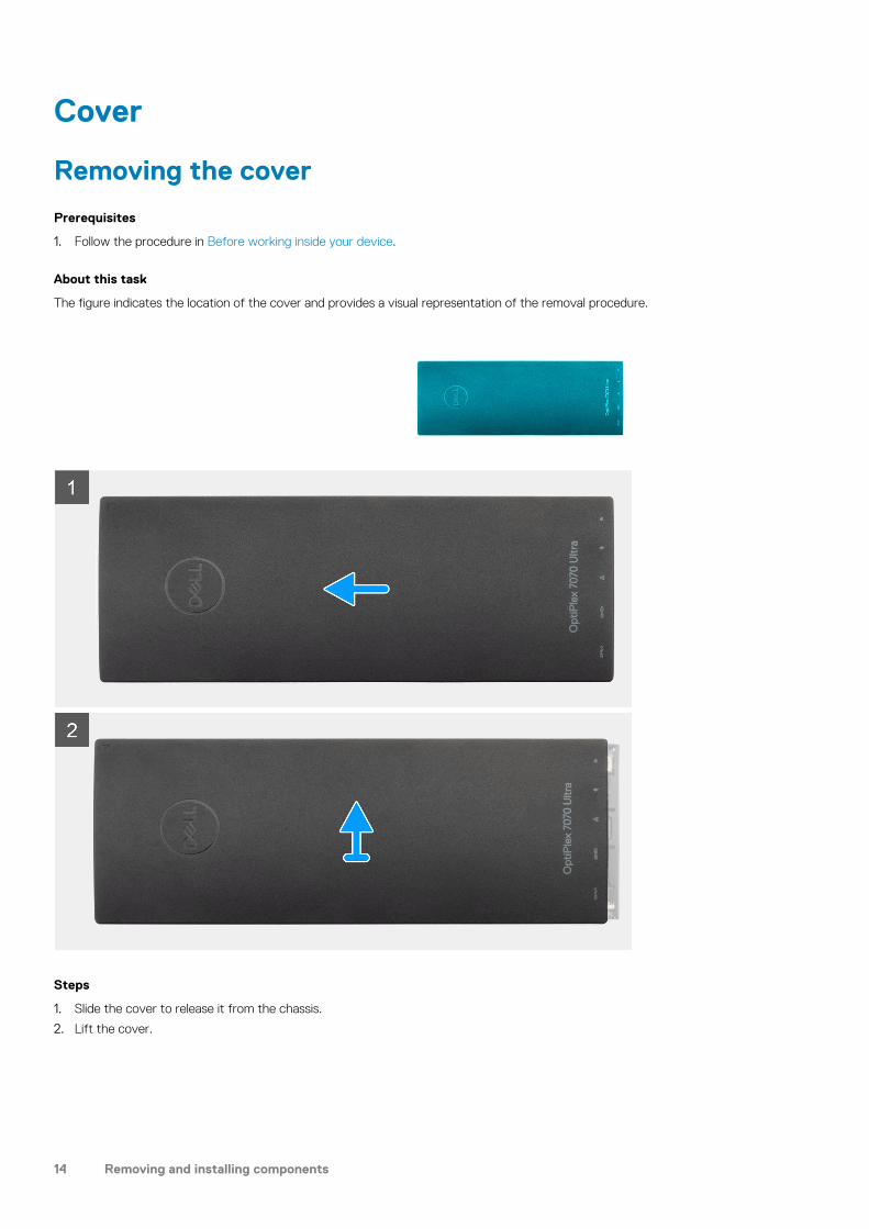
Installing the solid-state drive
Prerequisites
If you are replacing a component, remove the existing component before performing the installation procedure.
About this task
The figure indicates the location of the M.2 2230 solid-state drive and provides a visual representation of the installation procedure.
Steps
1. Align and adhere the SSD thermal pad in the mark on the system board.
NOTE: Check the adhesive direction before adhering it to the system board.
2. Align the notch on the solid-state drive with the connector on the system board and slide the solid-state drive at an angle into the slot.
Removing and installing components 21

3. Replace the (M2x3.5) screw to secure the solid-state drive module to the system board.
Next steps
1. Install the cover.2. Follow the procedure in After working on your device.
System fan
Removing the system fan
Prerequisites
1. Follow the procedure in Before working inside your device.2. Remove the cover.
About this task
The figure indicates the location of the system fan and provides a visual representation of the removal procedure.
Steps
1. Release the system fan from the retention hook on the fan tray.
2. Disconnect the system fan cable from the connector on the system board.
3. Slide the system fan out from the guiding rails on the heat-sink bracket.
Installing the system fan
Prerequisites
If you are replacing a component, remove the existing component before performing the installation procedure.
22 Removing and installing components

About this task
The figure indicates the location of the system fan and provides a visual representation of the installation procedure.
Steps
1. Connect the system fan cable to the connector on the system board.
2. Align the tabs on the system fan with the guiding rails on the heat-sink bracket.
3. Place the system fan into the fan tray until it clicks into place.
Next steps
1. Install the cover.2. Follow the procedure in After working on your device.
Power button
Removing the power button
Prerequisites
1. Follow the procedure in Before working inside your device.2. Remove the cover.3. Remove the system fan.
About this task
The figure indicates the location of the power button and provides a visual representation of the removal procedure.
Removing and installing components 23

Steps
1. Disconnect the power-button cable from the connector on the system board.
2. Unroute the power-button cable from the routing guide.
NOTE: Observe the routing of the power-button cable inside the chassis as you remove them. Route the cable
properly when you replace the component to prevent the cable from being pinched or crimped.
3. Remove the (M2x3) screw that secures the power button to the chassis.
4. Lift the power button out of the chassis.
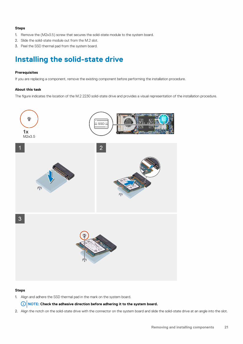
Installing the power button
Prerequisites
If you are replacing a component, remove the existing component before performing the installation procedure.
About this task
The figure indicates the location of the power button and provides a visual representation of the installation procedure.
24 Removing and installing components
Steps
1. Place the power button into the slot on the chassis.
2. Replace the (M2x3) screw to secure the power button to the chassis.
3. Route the power button cable through the routing guides on the chassis.
4. Connect the power-button cable to the connector on the system board.
Next steps
1. Install the system fan.2. Install the cover.3. Follow the procedure in After working on your device.
Removing and installing components 25

Coin-cell battery
Removing the coin-cell battery
Prerequisites
1. Follow the procedure in Before working inside your device.2. Remove the cover.3. Remove the system fan.
About this task
The figure indicates the location of the coin-cell battery and provides a visual representation of the removal procedure.
Steps
1. Disconnect the coin-cell battery cable from the connector on the system board.
2. Unroute the coin-cell battery cable from the routing guide.
NOTE: Observe the routing of the coin-cell battery cable inside the chassis as you remove them. Route the cable
properly when you replace the component to prevent the cable from being pinched or crimped.
26 Removing and installing components

3. Release the coin-cell retention clip from the securing hook and turn the clip to the other side.
4. Lift the coin-cell battery.
Installing the coin-cell battery
Prerequisites
If you are replacing a component, remove the existing component before performing the installation procedure.
About this task
The figure indicates the location of the coin-cell battery and provides a visual representation of the installation procedure.
Steps
1. Place the coin-cell battery in the slot on the chassis.
2. Close the coin-cell retention clip to secure the coin-cell battery.
3. Secure the coin-cell retention clip to the hook.
4. Route the coin-cell battery cable through the routing guide.
5. Connect the coin-cell battery cable to the connector on the system board.
Removing and installing components 27

Next steps
1. Install the system fan.2. Install the cover.3. Follow the procedure in After working on your device.
System board
Removing the system board
Prerequisites
1. Follow the procedure in Before working inside your device.2. Remove the hard-drive assembly.3. Remove the cover.4. Remove the system fan.5. Remove the WLAN card.6. Remove the solid-state drive.7. Remove the memory.
About this task
The figure indicates the location of the system board and provides a visual representation of the removal procedure.
28 Removing and installing components

Steps
1. Disconnect the power-button cable and the coin-cell battery cable from the connectors on the system board.
2. Unroute the power-button cable and the coin-cell battery cable from the routing guides.
3. Unroute the WLAN antenna cables from the routing guides.
NOTE: Observe the routing of the WLAN antenna cables inside the chassis as you remove them. Route these cables
properly when you replace the component to prevent the cables from being pinched or crimped.
4. Loosen the M2x3 captive screw and remove the four (M2x3) screws that secure the system board to the chassis.
5. Slightly lift and slide the system board out of the chassis.
Installing the system board
Prerequisites
If you are replacing a component, remove the existing component before performing the installation procedure.
About this task
The figure indicates the location of the system board and provides a visual representation of the installation procedure.
Removing and installing components 29

30 Removing and installing components

Steps
1. Align the connectors on the system board with the connector slots on the chassis.
2. Gently slide the system board into the chassis.
3. Tighten the M2x3 captive screw and replace the four (M2x3) screws to secure the system board to the chassis.
4. Route the power-button cable and the coin-cell battery cable through the routing guides.
5. Connect the power-button cable and the coin-cell battery cable to the connectors on the system board.
6. Route the WLAN antenna cables through the routing guides.
NOTE: The antennas should be aligned with the notches in the system board and the cable routing should not be
over the system board QR code.
Next steps
1. Install the solid-state drive.2. Install the memory.3. Install the WLAN card.4. Install the system fan.5. Install the cover.6. Install the hard-drive assembly.7. Follow the procedure in After working on your device.
Heat-sink
Removing the heat-sink
Prerequisites
1. Follow the procedure in Before working inside your device.2. Remove the hard-drive assembly.3. Remove the cover.4. Remove the system fan.5. Remove the WLAN card.
Removing and installing components 31

6. Remove the solid-state drive.7. Remove the memory.8. Remove the system board.
About this task
The figure indicates the location of the heatsink assembly and provides a visual representation of the removal procedure.
Steps
1. Loosen the four captive screws that secure the heat sink to the system board.
NOTE: Remove the screws in the order of the callout numbers [1, 2, 3, 4] as indicated on the heat sink.
2. Lift the heat sink away from the system board.
Installing the heat-sink
Prerequisites
If you are replacing a component, remove the existing component before performing the installation procedure.
32 Removing and installing components

About this task
The figure indicates the location of the heat-sink and provides a visual representation of the installation procedure.
Steps
1. Align the screws on the heat-sink with the screw holes on the system board.
2. Tighten the four captive screws to secure the heat-sink to the system board.
NOTE: Replace the screws in the order indicated on the heat-sink.
Next steps
1. Install the system board.2. Install the solid-state drive.3. Install the memory.4. Install the WLAN card.5. Install the system fan.6. Install the cover.7. Install the hard-drive assembly.8. Follow the procedure in After working on your device.
Removing and installing components 33

Replacing the chassisPrerequisites
1. Follow the procedure in Before working inside your device.2. Remove the hard-drive assembly.3. Remove the cover.4. Remove the system fan.5. Remove the WLAN card.6. Remove the solid-state drive.7. Remove the power button.8. Remove the memory.9. Remove the system board.10. Remove the coin cell battery.
About this task
After removing the above components, we are left with the chassis.
34 Removing and installing components

System setupCAUTION: Unless you are an expert computer user, do not change the settings in the BIOS Setup program. Certain
changes can make your computer work incorrectly.
NOTE: Before you change BIOS Setup program, it is recommended that you write down the BIOS Setup program screen
information for future reference.
Use the BIOS Setup program for the following purposes:
• Get information about the hardware installed in your computer, such as the amount of RAM and the size of the hard drive.• Change the system configuration information.• Set or change a user-selectable option, such as the user password, type of hard drive installed, and enabling or disabling base devices.
Topics:
• Boot menu• Navigation keys• Boot Sequence• System setup options• Updating the BIOS in Windows • System and setup password
Boot menuPress <F12> when the Dell logo appears to initiate a one-time boot menu with a list of the valid boot devices for the system. Diagnostics and BIOS Setup options are also included in this menu. The devices listed on the boot menu depend on the bootable devices in the system. This menu is useful when you are attempting to boot to a particular device or to bring up the diagnostics for the system. Using the boot menu does not make any changes to the boot order stored in the BIOS.
The options are:
• UEFI Boot:
• Windows Boot Manager
•
• Other Options:
• BIOS Setup• BIOS Flash Update• Diagnostics• Change Boot Mode Settings
Navigation keysNOTE: For most of the System Setup options, changes that you make are recorded but do not take effect until you
restart the system.
Keys Navigation
Up arrow Moves to the previous field.
Down arrow Moves to the next field.
Enter Selects a value in the selected field (if applicable) or follow the link in the field.
Spacebar Expands or collapses a drop-down list, if applicable.
3
System setup 35
Keys Navigation
Tab Moves to the next focus area.
Esc Moves to the previous page until you view the main screen. Pressing Esc in the main screen displays a message that prompts you to save any unsaved changes and restarts the system.
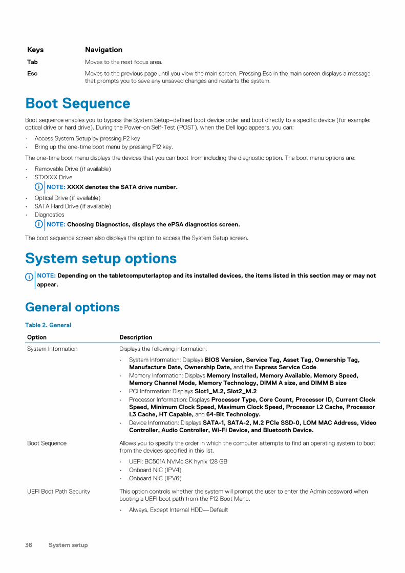
Boot SequenceBoot sequence enables you to bypass the System Setup–defined boot device order and boot directly to a specific device (for example: optical drive or hard drive). During the Power-on Self-Test (POST), when the Dell logo appears, you can:
• Access System Setup by pressing F2 key• Bring up the one-time boot menu by pressing F12 key.
The one-time boot menu displays the devices that you can boot from including the diagnostic option. The boot menu options are:
• Removable Drive (if available)• STXXXX Drive
NOTE: XXXX denotes the SATA drive number.
• Optical Drive (if available)• SATA Hard Drive (if available)• Diagnostics
NOTE: Choosing Diagnostics, displays the ePSA diagnostics screen.
The boot sequence screen also displays the option to access the System Setup screen.
System setup optionsNOTE: Depending on the tabletcomputerlaptop and its installed devices, the items listed in this section may or may not
appear.
General optionsTable 2. General
Option Description
System Information Displays the following information:
• System Information: Displays BIOS Version, Service Tag, Asset Tag, Ownership Tag, Manufacture Date, Ownership Date, and the Express Service Code.
• Memory Information: Displays Memory Installed, Memory Available, Memory Speed, Memory Channel Mode, Memory Technology, DIMM A size, and DIMM B size
• PCI Information: Displays Slot1_M.2, Slot2_M.2• Processor Information: Displays Processor Type, Core Count, Processor ID, Current Clock
Speed, Minimum Clock Speed, Maximum Clock Speed, Processor L2 Cache, Processor L3 Cache, HT Capable, and 64-Bit Technology.
• Device Information: Displays SATA-1, SATA-2, M.2 PCIe SSD-0, LOM MAC Address, Video Controller, Audio Controller, Wi-Fi Device, and Bluetooth Device.
Boot Sequence Allows you to specify the order in which the computer attempts to find an operating system to boot from the devices specified in this list.
• UEFI: BC501A NVMe SK hynix 128 GB• Onboard NIC (IPV4)• Onboard NIC (IPV6)
UEFI Boot Path Security This option controls whether the system will prompt the user to enter the Admin password when booting a UEFI boot path from the F12 Boot Menu.
• Always, Except Internal HDD—Default
36 System setup

Option Description
• Always, Except Internal HDD&PXE• Always• Never
Date/Time Allows you to set the date and time settings. Changes to the system date and time take effect immediately.
.
System informationTable 3. System Configuration
Option Description
Integrated NIC Allows you to configure the on-board LAN controller. The option Enable UEFI Network Stack is selected by default.
• Disabled = The internal LAN is off and not visible to the operating system.• Enabled = The internal LAN is enabled.• Enabled w/PXE = The internal LAN is enabled (with PXE boot) (selected by default)
SATA Operation Allows you to configure the operating mode of the integrated hard drive controller.
• Disabled = The SATA controllers are hidden• AHCI = SATA is configured for AHCI mode• RAID ON = SATA is configured to support RAID mode (selected by default)
Drives Allows you to enable or disable the various drives on-board:
• SATA-1 (enabled by default)• SATA-2 (enabled by default)• M.2 PCIe SSD-0 (enabled by default)
Smart Reporting This field controls whether hard drive errors for integrated drives are reported during system startup. The Enable Smart Reporting option is disabled by default.
USB Configuration Allows you to enable or disable the integrated USB controller for:
• Enable USB Boot Support• Enable Side USB Port• Enable Rear USB Port
All the options are enabled by default.
Rear USB Configuration Allows you to enable or disable Rear USB ports.
• Rear Port 1 (Left)• Rear Port 2 (Right)• Rear Type-C Port
Side USB Configuration Allows you to enable or disable Side USB ports.
• Side Port 1 w/PowerShare (Bottom)• Side Type-C Port
USB PowerShare This option configures the USB PowerShare feature behavior.
• Enable USB PowerShare - disabled by default.
This feature is intended to enable users to power or charge external devices, such as phones and portable music players, using the stored system battery power through the USN PowerShare port on the notebook, while the notebook is in a sleep state.
Audio Allows you to enable or disable the integrated audio controller. The option Enable Audio is selected by default.
System setup 37

Option Description
Both the options are selected by default.
VideoNOTE: The video setting is visible only when a video card is installed into the system.
Table 4. Video option
Options Descriptions
Primary Display This field determines which video controller becomes the primary display when multiple controllers are available in the system. If you select a device other that what you are currently using, you have to reconnect your video cable to your selected device.
• Auto• Intel HD Graphics
SecurityTable 5. Security
Option Description
Admin Password Allows you to set, change, and delete the admin password.
System Password Allows you to set, change, and delete the system password.
Internal HDD-1 Password This option lets you set, change, or delete the password on the internal hard disk drive (HDD) of the system.
Strong Password This option lets you enable or disable strong passwords for the system.
Password Configuration Allows you to control the minimum and maximum number of characters that are allowed for an administrative password and the system password. The range of characters is 4–32.
Password Bypass This option lets you bypass the System (Boot) Password and the internal hard drive password prompts during a system restart.
• Disabled—Always prompt for the system and internal hard drive password when they are set. This option is enabled by default.
• Reboot Bypass—Bypass the password prompts on Restarts (warm boots).
NOTE: The system will always prompt for the system and internal hard drive passwords when powered on from the off state (a cold boot). Also, the system will always prompt for passwords on any module bay HDDs that may be present.
Password Change This option lets you determine whether changes to the System and Hard Disk passwords are permitted when an administrator password is set.
Allow Non-Admin Password Changes - This option is enabled by default.
UEFI Capsule Firmware Updates This option controls whether this system enables BIOS updates via UEFI capsule update packages. This option is selected by default. Disabling this option blocks BIOS updates from services such as Microsoft Windows Update and Linux Vendor Firmware Service (LVFS).
TPM 2.0 Security Allows you to control whether the Trusted Platform Module (TPM) is visible to the operating system.
• TPM On (default)• Clear• PPI Bypass for Enable Commands• PPI Bypass for Disable Commands• PPI Bypass for Clear Commands
38 System setup

Option Description
• Attestation Enable (default)• Key Storage Enable (default)• SHA-256 (default)
Choose any one option:
• Disabled• Enabled (default)
Absolute This field lets you Enable, Disable, or Permanently Disable the BIOS module interface of the optional Absolute Persistence Module service from Absolute Software.
• Enabled - This option is selected by default.• Disabled• Permanently Disabled
Chassis Intrusion This field controls the chassis intrusion feature.
• Disabled (default)• Enabled• On-Silent
Admin Setup Lockout Allows you to prevent users from entering Setup when Admin password is set. This option is not set by default.
Master Password Lockout Allows you to disable master password support Hard Disk passwords need to be cleared before the settings can be changed. This option is not set by default.
SMM Security Mitigation Allows you to enable or disable additional UEFI SMM Security Mitigation protections. This option is not set by default.
Secure bootTable 6. Secure Boot
Option Description
Secure Boot Enable Allows you to enable or disable Secure Boot feature
• Secure Boot Enable
Option is not selected.
Secure Boot Mode Allows you to modify the behavior of Secure Boot to allow evaluation or enforcement of UEFI driver signatures.
• Deployed Mode (default)• Audit Mode
Expert key Management Allows you to manipulate the security key databases only if the system is in Custom Mode. The Enable Custom Mode option is disabled by default. The options are:
• PK (default)• KEK• db• dbx
If you enable the Custom Mode, the relevant options for PK, KEK, db, and dbx appear. The options are:
• Save to File- Saves the key to a user-selected file• Replace from File- Replaces the current key with a key from a user-selected file• Append from File- Adds a key to the current database from a user-selected file• Delete- Deletes the selected key• Reset All Keys- Resets to default setting• Delete All Keys- Deletes all the keys
System setup 39

Option Description
NOTE: If you disable the Custom Mode, all the changes made will be erased and the keys will restore to default settings.
Intel Software Guard ExtensionsTable 7. Intel Software Guard Extensions
Option Description
Intel SGX Enable This field specifies you to provide a secured environment for running code/storing sensitive information in the context of the main OS.
Click one of the following options:
• Disabled• Enabled• Software controlled—Default
Enclave Memory Size This option sets SGX Enclave Reserve Memory Size
Click one of the following options:
• 32 MB• 64 MB• 128 MB—Default
PerformanceTable 8. Performance
Option Description
Multi Core Support This field specifies whether the process has one or all cores enabled. The performance of some applications improves with the additional cores.
• All—Default• 1• 2• 3
Intel SpeedStep Allows you to enable or disable the Intel SpeedStep mode of processor.
• Enable Intel SpeedStep.
This option is set by default.
C-States Control Allows you to enable or disable the additional processor sleep states.
• C states
This option is set by default.
Intel TurboBoost Allows you to enable or disable the Intel TurboBoost mode of the processor.
• Enable Intel TurboBoost.
This option is set by default.
40 System setup

Option Description
HyperThread Control Allows you to enable or disable the HyperThreading in the processor.
• Disabled• Enabled—Default
Power managementTable 9. Power management
Options Descriptions
AC Behavior This field specifies how the system will behave when AC power is restored after a AC power loss.
• Power Off (Default)• Power On• Last Power State
Enable Intel Speed Shift Technology This option is used to enable/disable Intel Speed Shift Technology support.
• Enable Intel Speed Shift Technology (Default).
Auto On Time Allows you to set the time at which the computer must turn on automatically. The options are:
• Disabled (Default)• Every Day• Weekdays• Select Days
Deep Sleep Controls This field determines how aggressive the system is at conserving power while Shut down (S5) or in Hibernate (S4 mode). When this option is enabled, more power is conserved.
• Disabled (Default)• Enabled in S5 only• Enabled in S4 and S5
USB Wake Support Allows you to enable USB devices to wake the system from Standby.
NOTE: This feature is only functional when the AC power adapter is connected. If the AC power adapter is removed during Standby, the system setup removes power from all the USB ports to conserve battery power.
• Enable USB Wake Support
Wake on LAN/WLAN Allows you to enable or disable the feature that powers on the computer from the Off state when triggered by a LAN signal.
• Disabled• LAN Only• WLAN Only• LAN or WLAN• LAN with PXE Boot
Default setting: Disabled
Block Sheep This option lets you block entering to sleep in operating system environment. When enabled system will not go to sleep.
Block Sleep - is disabled.
System setup 41

POST behaviorTable 10. POST behavior
Options Descriptions
Numlock LED Allows you to enable the Numlock option when the computer boots.
Enable Network. This option is enabled by default.
Keyboard errors This field specifies whether the keyboard related errors are reported.
Enable Network Error Detention. This option is enabled by default.
Fastboot Allows you to speed up the boot process by bypassing some of the compatibility steps. The options are:
• Minimal• Thorough—enabled by default• Auto
Extend BIOS POST time Allows you to create an extra preboot delay. The options are:
• 0 seconds—enabled by default.• 5 seconds• 10 seconds
Full Screen Logo This option displays full screen logo if your image match screen resolution. Enable Full Screen Logo—not enabled
Warnings and Errors This option cause the boot process to only pause whe warnings or errors are detected, rather than stop, prompt and wait for user input.
ManageabilityTable 11. Manageability
Options Descriptions
Intel AMT Capability Allows you to provision AMT and MEBx Hotkey function is enabled, during the system boot.
• Disabled• Enabled - by default• Restrict MEBx Access
USB Provision When enabled, Intel AMT can be provisioned using the local provisioning file via a USB storage device.
• Enable USB Provision—disabled by default.
MEBX Hotkey Allows you to specify whether the MEBx Hotkey function should enable, during the system boot.
• Enable MEBx hotkey—enabled by default.
Virtualization supportOption Description
Virtualization This field specifies whether a virtual Machine Monitor (VMM) can utilize the conditional hardware capabilities provided by Intel Virtualization Technology.
42 System setup

Option Description
Enable Intel Virtualization Technology—enabled by default.
VT for Direct I/O Enables or disables the Virtual Machine Monitor (VMM) from utilizing the additional hardware capabilities provided by Intel® Virtualization technology for direct I/O.
Enable VT for Direct I/O - enabled by default.
Trusted Execution This option specifies whether a Measured Virtual Machine Monitor (MVMM) can utilize the additional hardware capabilities provided by Intel Trusted Execution Technology. The TPM Virtualization Technology, and the Virtualization technology for direct I/O must be enabled to use this feature.
Trusted Execution - disabled by default.
WirelessTable 12. Wireless
Options Descriptions
Wireless Device Enable Allows you to enable or disable the internal wireless devices.
• WLAN/Wigig• Bluetooth
The options are enabled by default.
Maintenance screenTable 13. Maintenance screen
Options Descriptions
Service Tag Displays the Service Tag of your computer.
Asset Tag Allows you to create a system asset tag if an asset tag is not already set. This option is not set by default.
SERR Message This field controls the SERR message mechanism.
• Enable SERR Messages—Enabled by default.
BIOS Downgrade This field controls flashing of the system firmware to previous revisions.
• Enable BIOS Downgrade—Enabled by default.
Data Wipes This field enables users to securely erase data from all internal storage devices.
• Wipe on Next Boot-Disabled by default.
BIOS Recovery This field enables you to recover from certain corrupted BIOS conditions from a recover file on the user primary hard drive or an external USB key.
• BIOS Recovery from Hard Drive—Enabled by default
• BIOS Auto-Recovery—Disabled by default
System setup 43

System logsTable 14. System logs
Options Descriptions
BIOS Event Allows you to view and clear the System Setup (BIOS) POST events.
Advanced ConfigurationTable 15. Advanced Configuration
Options Descriptions
ASPM Set the ASPM (Active State Power Management) level:
• Auto: There is handshaking between the device and PCI Express hub to determine the best ASPM mode supported by the deviceEnabled by default.
• Disabled: ASPM power management is turned off always.• L1 Only: ASPM power management is set to use L1
Updating the BIOS in WindowsPrerequisites
It is recommended to update your BIOS (System Setup), when you replace the system board or if an update is available. For laptops, ensure that your computer battery is fully charged and connected to a power outlet.
About this task
NOTE: If BitLocker is enabled, it must be suspended prior to updating the system BIOS, and then re-enabled after the
BIOS update is completed.
Steps
1. Restart the computer.
2. Go to Dell.com/support.
• Enter the Service Tag or Express Service Code and click Submit.• Click Detect Product and follow the instructions on screen.
3. If you are unable to detect or find the Service Tag, click Choose from all products.
4. Choose the Products category from the list.
NOTE: Choose the appropriate category to reach the product page
5. Select your computer model and the Product Support page of your computer appears.
6. Click Get drivers and click Drivers and Downloads.The Drivers and Downloads section opens.
7. Click Find it myself.
8. Click BIOS to view the BIOS versions.
9. Identify the latest BIOS file and click Download.
10. Select your preferred download method in the Please select your download method below window, click Download File.The File Download window appears.
11. Click Save to save the file on your computer.
12. Click Run to install the updated BIOS settings on your computer.
Follow the instructions on the screen.
44 System setup

Updating BIOS on systems with BitLocker enabledCAUTION: If BitLocker is not suspended before updating the BIOS, the next time you reboot the system it will not
recognize the BitLocker key. You will then be prompted to enter the recovery key to progress and the system will ask for
this on each reboot. If the recovery key is not known this can result in data loss or an unnecessary operating system
reinstall. For more information about this subject, see Knowledge Article: https://www.dell.com/support/article/
sln153694
Updating your BIOS from the F12 One-Time Boot Menu
About this task
You can update your BIOS outside the operating system by using the <F12> one time boot menu. See Dell Knowledge Article for more information about this subject: Flashing the BIOS from the F12 One-Time Boot Menu: https://www.dell.com/support/article/sln305230
Updating your system BIOS using a USB flash drive
About this task
If the system cannot load into Windows but there is still a need to update the BIOS, download the BIOS file using another system and save it to a bootable USB Flash Drive.
NOTE: You will need to use a bootable USB Flash drive. Please refer to the following article for further details: https://
www.dell.com/support/article/sln143196/
Steps
1. Download the BIOS update .EXE file to another system.
2. Copy the file e.g. O9010A12.EXE onto the bootable USB Flash drive.
3. Insert the USB Flash drive into the system that requires the BIOS update.
4. Restart the system and press F12 when the Dell Splash logo appears to display the One Time Boot Menu.
5. Using arrow keys, select USB Storage Device and click Return.
6. The system will boot to a Diag C:\> prompt.
7. Run the file by typing the full filename e.g. O9010A12.exe and press Return.
8. The BIOS Update Utility will load, follow the instructions on screen.
Figure 1. DOS BIOS Update Screen
System setup 45

System and setup passwordTable 16. System and setup password
Password type Description
System password Password that you must enter to log on to your system.
Setup password Password that you must enter to access and make changes to the BIOS settings of your computer.
You can create a system password and a setup password to secure your computer.
CAUTION: The password features provide a basic level of security for the data on your computer.
CAUTION: Anyone can access the data stored on your computer if it is not locked and left unattended.
NOTE: System and setup password feature is disabled.
Assigning a system setup password
Prerequisites
You can assign a new System or Admin Password only when the status is in Not Set.
About this task
To enter the system setup, press F2 immediately after a power-on or re-boot.
Steps
1. In the System BIOS or System Setup screen, select Security and press Enter.The Security screen is displayed.
2. Select System/Admin Password and create a password in the Enter the new password field.
Use the following guidelines to assign the system password:
• A password can have up to 32 characters.• The password can contain the numbers 0 through 9.• Only lower case letters are valid, upper case letters are not allowed.• Only the following special characters are allowed: space, (”), (+), (,), (-), (.), (/), (;), ([), (\), (]), (`).
3. Type the system password that you entered earlier in the Confirm new password field and click OK.
4. Press Esc and a message prompts you to save the changes.
5. Press Y to save the changes.The computer reboots.
Deleting or changing an existing system setup password
Prerequisites
Ensure that the Password Status is Unlocked (in the System Setup) before attempting to delete or change the existing System and/or Setup password. You cannot delete or change an existing System or Setup password, if the Password Status is Locked.
About this task
To enter the System Setup, press F2 immediately after a power-on or reboot.
Steps
1. In the System BIOS or System Setup screen, select System Security and press Enter.
46 System setup

The System Security screen is displayed.
2. In the System Security screen, verify that Password Status is Unlocked.
3. Select System Password, alter or delete the existing system password and press Enter or Tab.
4. Select Setup Password, alter or delete the existing setup password and press Enter or Tab.
NOTE: If you change the System and/or Setup password, re-enter the new password when prompted. If you delete
the System and/or Setup password, confirm the deletion when prompted.
5. Press Esc and a message prompts you to save the changes.
6. Press Y to save the changes and exit from System Setup.The computer reboot.
System setup 47

Troubleshooting
Enhanced Pre-Boot System Assessment (ePSA) diagnosticsAbout this task
The ePSA diagnostics (also known as system diagnostics) performs a complete check of your hardware. The ePSA is embedded with the BIOS and is launched by the BIOS internally. The embedded system diagnostics provides a set of options for particular devices or device groups allowing you to:
• Run tests automatically or in an interactive mode• Repeat tests• Display or save test results• Run thorough tests to introduce additional test options to provide extra information about the failed device(s)• View status messages that inform you if tests are completed successfully• View error messages that inform you of problems encountered during testing
NOTE: Some tests for specific devices require user interaction. Always ensure that you are present at the computer
terminal when the diagnostic tests are performed.
For more information, see Dell EPSA Diagnostic 3.0.
Running the ePSA diagnostics
Steps
1. Turn on your computer.
2. As the computer boots, press the F12 key as the Dell logo appears.
3. On the boot menu screen, select the Diagnostics option.
4. Click the arrow at the bottom left corner.Diagnostics front page is displayed.
5. Click the arrow in the lower-right corner to go to the page listing.The items detected are listed.
6. To run a diagnostic test on a specific device, press Esc and click Yes to stop the diagnostic test.
7. Select the device from the left pane and click Run Tests.
8. If there are any issues, error codes are displayed.Note the error code and validation number and contact Dell.
WiFi power cycleAbout this task
If your computer is unable to access the internet due to WiFi connectivity issues a WiFi power cycle procedure may be performed. The following procedure provides the instructions on how to conduct a WiFi power cycle:
NOTE: Some ISPs (Internet Service Providers) provide a modem/router combo device.
Steps
1. Turn off your computer.
4
48 Troubleshooting

2. Turn off the modem.
3. Turn off the wireless router.
4. Wait for 30 seconds.
5. Turn on the wireless router.
6. Turn on the modem.
7. Turn on your computer.
Diagnostic LEDInstead of beep codes, errors are indicated via the bicolor Battery Charge/Status LED. A specific blink pattern is followed by flashing a pattern of flashes in amber, followed by white. The pattern then repeats.
NOTE: The diagnostic pattern consists of a two-digit number being represented by a first group of LED blinks (1
through 9) in amber, followed by a 1.5 second pause with the LED off, and then a second group of LED blinks (1 through
9) in white. This is then followed by a three second pause, with the LED off, before repeating over again. Each LED blink
takes 1.5 seconds.
The system will not shutdown when displaying the Diagnostic Error Codes.
Diagnostic Error Codes will always supersede any other use of the LED.
Table 17. Diagnostic LED
Blinking Patterns Problem description Suggested resolutions
Amber White
2 1 CPU failure • Run the Intel CPU diagnostics tools
• If problem persists, replace the system board
2 2 System board failure (included BIOS corruption or ROM error) • Flash latest BIOS version• If problem persists, replace
the system board
2 3 No memory/ RAM detected • Confirm that the memory module is installed properly
• If problem persists, replace the system board
2 4 Memory/ RAM failure • Reset the memory module• If problem persists, replace
the system board
2 5 Invalid memory installed • Reset the memory module• If problem persists, replace
the system board
2 6 System board/ Chipset error • Flash latest BIOS version• If problem persists, replace
the system board
2 7 LCD failure • Flash latest BIOS version• If problem persists, replace
the system board
2 8 LCD Power rail failure Replace the system board
3 1 CMOS battery failure • Reset the CMOS battery connection
• If problem persists, replace the system board
Troubleshooting 49

Blinking Patterns Problem description Suggested resolutions
Amber White
3 2 PCI or Video card/ chip failure Replace the system board
3 3 BIOS Recovery Image not found • Flash latest BIOS version• If problem persists, replace
the system board
3 4 BIOS Recovery Image found but invalid • Flash latest BIOS version• If problem persists, replace
the system board
3 5 Power Rail Failure • EC ran into power sequencing failure
• If problem persists, replace the system board
3 6 SBIOS Flash Corruption • Flash corruption detected by SBIOS
• If problem persists, replace the system board
3 7 ME Error • Timeout waiting on ME to reply to HECI message
• If problem persists, replace the system board
NOTE: For diagnostics pattern 2-amber, 8-white connects an external monitor to isolate between system board or
graphics controller failure.
50 Troubleshooting

Getting help
Topics:
• Contacting Dell
Contacting DellPrerequisites
NOTE: If you do not have an active Internet connection, you can find contact information on your purchase invoice,
packing slip, bill, or Dell product catalog.
About this task
Dell provides several online and telephone-based support and service options. Availability varies by country and product, and some services may not be available in your area. To contact Dell for sales, technical support, or customer service issues:
Steps
1. Go to Dell.com/support.
2. Select your support category.
3. Verify your country or region in the Choose a Country/Region drop-down list at the bottom of the page.
4. Select the appropriate service or support link based on your need.
5
Getting help 51


![Torre OptiPlex 7070 - Dell€¦ · Configuração do BIOS SPI (Serial Peripheral Component Interconnect Interface [interface para computador de pequeno porte]) 256 Mbit (32 MB) localizados](https://img.dokumen.tips/doc/110x75/5f8679bbdc58ac65de595408/torre-optiplex-7070-dell-configurao-do-bios-spi-serial-peripheral-component.jpg)