Embed Size (px)
Citation preview
Dell OptiPlex 5250 All-In-OneOwner's Manual
Regulatory Model: W14BRegulatory Type: W14B002
Notes, cautions, and warnings
NOTE: A NOTE indicates important information that helps you make better use of your product.
CAUTION: A CAUTION indicates either potential damage to hardware or loss of data and tells you how to avoid the problem.
WARNING: A WARNING indicates a potential for property damage, personal injury, or death.
© 2017 Dell Inc. or its subsidiaries. All rights reserved. Dell, EMC, and other trademarks are trademarks of Dell Inc. or its subsidiaries. Other trademarks may be trademarks of their respective owners.
2017 - 02
Rev. A00
Contents
1 Working on your computer............................................................................................................................. 7Before working inside your computer.............................................................................................................................. 7Safety instructions............................................................................................................................................................. 7Recommended tools.......................................................................................................................................................... 8Turning off your computer................................................................................................................................................ 8After working inside your computer.................................................................................................................................8Important Information........................................................................................................................................................8
2 Removing and installing components............................................................................................................. 9Stand................................................................................................................................................................................... 9
Removing the stand.....................................................................................................................................................9Installing the stand......................................................................................................................................................10
Cable cover....................................................................................................................................................................... 10Removing the cable cover.........................................................................................................................................10Installing the cable cover........................................................................................................................................... 10
Back cover..........................................................................................................................................................................11Removing the back cover...........................................................................................................................................11Installing the back cover............................................................................................................................................ 12
Speaker cover................................................................................................................................................................... 12Removing the speaker cover.....................................................................................................................................12Installing the speaker cover....................................................................................................................................... 14
Hard drive.......................................................................................................................................................................... 14Removing the hard drive assembly...........................................................................................................................14Installing the hard drive assembly.............................................................................................................................15
Optical drive...................................................................................................................................................................... 15Removing the optical drive assembly.......................................................................................................................15Installing the optical drive assembly......................................................................................................................... 16
System board shield..........................................................................................................................................................17Removing the system board shield........................................................................................................................... 17Installing the system board shield............................................................................................................................. 17
Memory module................................................................................................................................................................ 18Removing the memory module................................................................................................................................. 18Installing the memory module................................................................................................................................... 18
Solid State Drive (SSD)....................................................................................................................................................19Removing the SSD card.............................................................................................................................................19Installing the SSD card............................................................................................................................................... 19
Coin cell battery............................................................................................................................................................... 20Removing the coin cell battery.................................................................................................................................20Installing the coin cell battery................................................................................................................................... 20
WLAN card........................................................................................................................................................................ 21Removing the WLAN card.........................................................................................................................................21Installing the WLAN card........................................................................................................................................... 21
Heat sink........................................................................................................................................................................... 22
Contents 3
Removing the heat sink ............................................................................................................................................22Installing the heat sink............................................................................................................................................... 22
Speaker............................................................................................................................................................................. 23Removing the speaker module................................................................................................................................. 23Installing the speaker module................................................................................................................................... 24
Power supply unit.............................................................................................................................................................24Removing the Power Supply Unit (PSU)................................................................................................................24Installing the Power Supply Unit (PSU).................................................................................................................. 27
VESA mount bracket....................................................................................................................................................... 27Removing the VESA mount bracket........................................................................................................................ 27Installing the VESA mount bracket.......................................................................................................................... 28
Converter board............................................................................................................................................................... 28Removing the converter board................................................................................................................................ 28Installing the converter board...................................................................................................................................29
System fan........................................................................................................................................................................30Removing the system fan......................................................................................................................................... 30Installing the system fan........................................................................................................................................... 30
Intrusion switch.................................................................................................................................................................31Removing the intrusion switch..................................................................................................................................31Installing the intrusion switch................................................................................................................................... 32
Power and On-Screen Display (OSD) buttons board..................................................................................................32Removing the power and On-Screen Display (OSD) buttons board...................................................................32Installing the power and OSD buttons board..........................................................................................................33
Processor.......................................................................................................................................................................... 33Removing the processor........................................................................................................................................... 33Installing the processor..............................................................................................................................................34
System board................................................................................................................................................................... 35Removing the system board.....................................................................................................................................35Installing the system board....................................................................................................................................... 38System board layout.................................................................................................................................................. 39
3 Technology and components....................................................................................................................... 40Processors........................................................................................................................................................................ 40
Skylake — 6th Generation Intel Core processors..................................................................................................40Kaby Lake — 7th Generation Intel Core processors..............................................................................................41Identifying processors in Windows 10...................................................................................................................... 41Identifying processors in Windows 7....................................................................................................................... 42
Chipsets............................................................................................................................................................................ 42Identifying the chipset in Device Manager on Windows 10.................................................................................. 42
Storage options................................................................................................................................................................ 42Hard drives..................................................................................................................................................................42Solid State Drives (SSD)........................................................................................................................................... 42Identifying the hard drive in Windows 10................................................................................................................ 43Entering BIOS setup.................................................................................................................................................. 43
Memory configurations................................................................................................................................................... 43Verifying system memory in Windows 10 and Windows 7 ...................................................................................43
DDR4................................................................................................................................................................................. 44
4 Contents
Key Specifications......................................................................................................................................................44DDR4 Details...............................................................................................................................................................45
4 System setup...............................................................................................................................................46Boot Sequence.................................................................................................................................................................46Navigation keys................................................................................................................................................................ 46System setup options...................................................................................................................................................... 47System setup options...................................................................................................................................................... 47
General screen options..............................................................................................................................................47System configuration screen options...................................................................................................................... 48Security screen options.............................................................................................................................................49Secure boot screen options.......................................................................................................................................51Intel Software Guard Extensions options................................................................................................................52Performance screen options.................................................................................................................................... 52Power management screen options........................................................................................................................53POST behavior screen options.................................................................................................................................54Virtualization support screen options......................................................................................................................54Maintenance screen options.................................................................................................................................... 55System Log screen options...................................................................................................................................... 55
Updating the BIOS ......................................................................................................................................................... 55System and setup password.......................................................................................................................................... 56
Assigning a system password and setup password...............................................................................................56Deleting or changing an existing system and/or setup password........................................................................57
5 Troubleshooting your computer................................................................................................................... 58Enhanced Pre-Boot System Assessment (ePSA) diagnostics...................................................................................58
Running the ePSA diagnostics................................................................................................................................. 58Power supply—built in self test (BIST)........................................................................................................................ 58LCD built in self test (BIST)............................................................................................................................................59
Invoking BIST with user modes.................................................................................................................................61OSD toggle.................................................................................................................................................................. 61ePSA.............................................................................................................................................................................61
6 Technical specifications............................................................................................................................... 63System specifications......................................................................................................................................................63Memory specifications.................................................................................................................................................... 63Video specifications.........................................................................................................................................................64Audio specifications......................................................................................................................................................... 64Communication specifications........................................................................................................................................64Cards specifications.........................................................................................................................................................65Display specifications.......................................................................................................................................................65Drives specifications........................................................................................................................................................65Port and connector specifications.................................................................................................................................65Power specifications....................................................................................................................................................... 65Camera (optional) specifications................................................................................................................................... 66Stand specifications........................................................................................................................................................ 66Physical specifications.....................................................................................................................................................66
Contents 5

Environmental specifications..........................................................................................................................................66
7 Contacting Dell............................................................................................................................................ 68
6 Contents
Working on your computer
Before working inside your computerTo avoid damaging your computer, perform the following steps before you begin working inside the computer.
1 Ensure that you follow the Safety instructions.
2 Ensure that your work surface is flat and clean to prevent the computer cover from being scratched.
3 Turn off your computer.
CAUTION: To disconnect a network cable, first unplug the cable from your computer and then unplug the cable from the network device.
4 Disconnect all network cables from the computer.
5 Disconnect your computer and all attached devices from their electrical outlets.
6 Press and hold the power button while the computer is unplugged to ground the system board.
7 Remove the cover.
CAUTION: Before touching anything inside your computer, ground yourself by touching an unpainted metal surface, such as the metal at the back of the computer. While you work, periodically touch an unpainted metal surface to dissipate static electricity, which could harm internal components.
Safety instructionsUse the following safety guidelines to protect your computer from potential damage and to ensure your personal safety. Unless otherwise noted, each procedure included in this document assumes that the following conditions exist:
• You have read the safety information that shipped with your computer.
• A component can be replaced or, if purchased separately, installed by performing the removal procedure in reverse order.
WARNING: Disconnect all power sources before opening the computer cover or panels. After you finish working inside the computer, replace all covers, panels, and screws before connecting to the power source.
WARNING: Before working inside your computer, read the safety information that shipped with your computer. For additional safety best practices information, see the Regulatory Compliance Homepage at www.Dell.com/regulatory_compliance
CAUTION: Many repairs may only be done by a certified service technician. You should only perform troubleshooting and simple repairs as authorized in your product documentation, or as directed by the online or telephone service and support team. Damage due to servicing that is not authorized by Dell is not covered by your warranty. Read and follow the safety instructions that came with the product.
CAUTION: To avoid electrostatic discharge, ground yourself by using a wrist grounding strap or by periodically touching an unpainted metal surface, such as a connector on the back of the computer.
CAUTION: Handle components and cards with care. Do not touch the components or contacts on a card. Hold a card by its edges or by its metal mounting bracket. Hold a component such as a processor by its edges, not by its pins.
CAUTION: When you disconnect a cable, pull on its connector or on its pull-tab, not on the cable itself. Some cables have connectors with locking tabs; if you are disconnecting this type of cable, press in on the locking tabs before you disconnect the cable. As you pull connectors apart, keep them evenly aligned to avoid bending any connector pins. Also, before you connect a cable, ensure that both connectors are correctly oriented and aligned.
NOTE: The color of your computer and certain components may appear differently than shown in this document.
1
Working on your computer 7
Recommended toolsThe procedures in this document require the following tools:
• Small flat blade screwdriver
• Phillips # 1 screwdriver
• Small plastic scribe
• Hex screwdriver
Turning off your computer
After working inside your computerAfter you complete any replacement procedure, ensure that you connect any external devices, cards, and cables before turning on your computer.
1 Replace the cover.
CAUTION: To connect a network cable, first plug the cable into the network device and then plug it into the computer.
2 Connect any telephone or network cables to your computer.
3 Connect your computer and all attached devices to their electrical outlets.
4 Turn on your computer.
5 If required, verify that the computer works correctly by running ePSA diagnostics.
Important InformationNOTE: Avoid using the touchscreen in dusty, hot, or humid environments.
NOTE: Sudden change in temperature may cause condensation on the inner surface of the glass screen, which will disappear after a short time and does not affect normal usage.
8 Working on your computer
Removing and installing componentsThis section provides detailed information on how to remove or install the components from your computer.
Stand
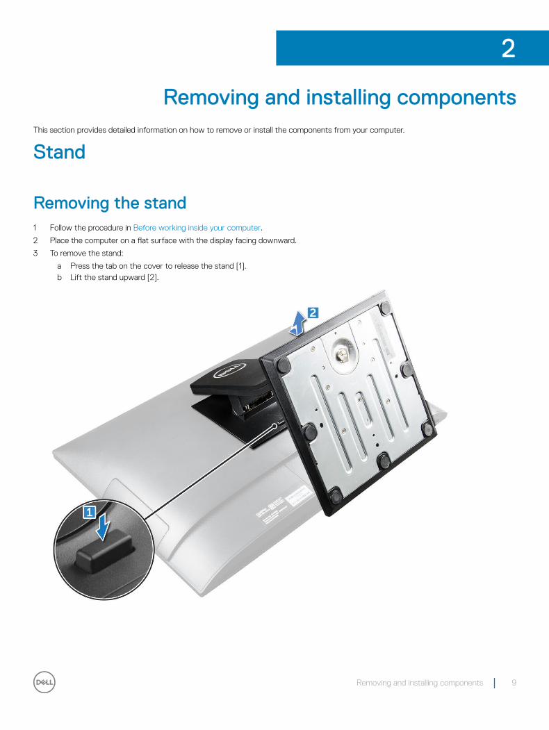
Removing the stand1 Follow the procedure in Before working inside your computer.
2 Place the computer on a flat surface with the display facing downward.
3 To remove the stand:
a Press the tab on the cover to release the stand [1].b Lift the stand upward [2].
2
Removing and installing components 9
Installing the stand1 Align the stand and slide it on the back of the computer.
2 Press the stand down till it snaps in.
3 Follow the procedure in After working inside your computer.
Cable cover
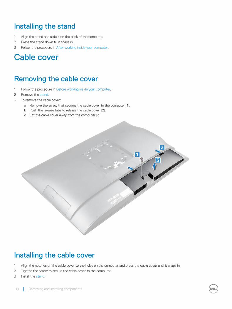
Removing the cable cover1 Follow the procedure in Before working inside your computer.
2 Remove the stand.
3 To remove the cable cover:
a Remove the screw that secures the cable cover to the computer [1].b Push the release tabs to release the cable cover [2].c Lift the cable cover away from the computer [3].
Installing the cable cover1 Align the notches on the cable cover to the holes on the computer and press the cable cover until it snaps in.
2 Tighten the screw to secure the cable cover to the computer.
3 Install the stand.
10 Removing and installing components
4 Follow the procedure in After working inside your computer.
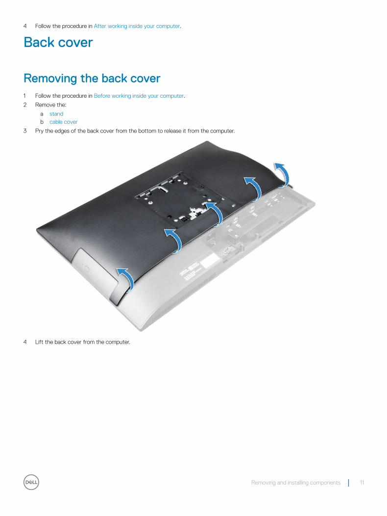
Back cover
Removing the back cover1 Follow the procedure in Before working inside your computer.
2 Remove the:
a standb cable cover
3 Pry the edges of the back cover from the bottom to release it from the computer.
4 Lift the back cover from the computer.
Removing and installing components 11
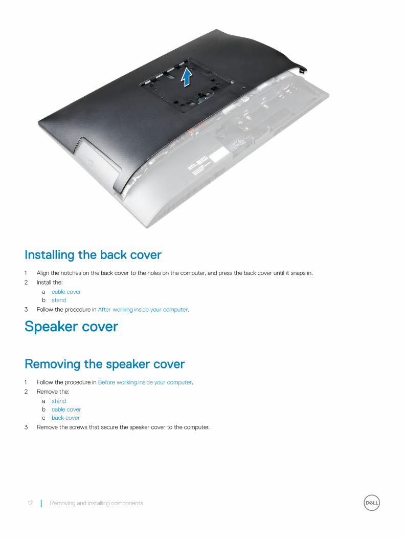
Installing the back cover1 Align the notches on the back cover to the holes on the computer, and press the back cover until it snaps in.
2 Install the:
a cable coverb stand
3 Follow the procedure in After working inside your computer.
Speaker cover
Removing the speaker cover1 Follow the procedure in Before working inside your computer.
2 Remove the:
a standb cable coverc back cover
3 Remove the screws that secure the speaker cover to the computer.
12 Removing and installing components
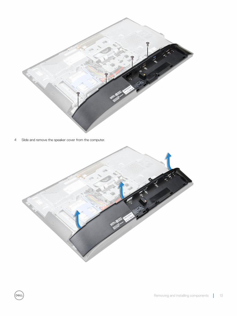
4 Slide and remove the speaker cover from the computer.
Removing and installing components 13
Installing the speaker cover1 Align the speaker cover to its position on the back of the computer.
2 Tighten the screws to secure the speaker cover to the computer.
3 Install the:
a back coverb cable coverc stand
4 Follow the procedure in After Working Inside Your Computer.
Hard drive
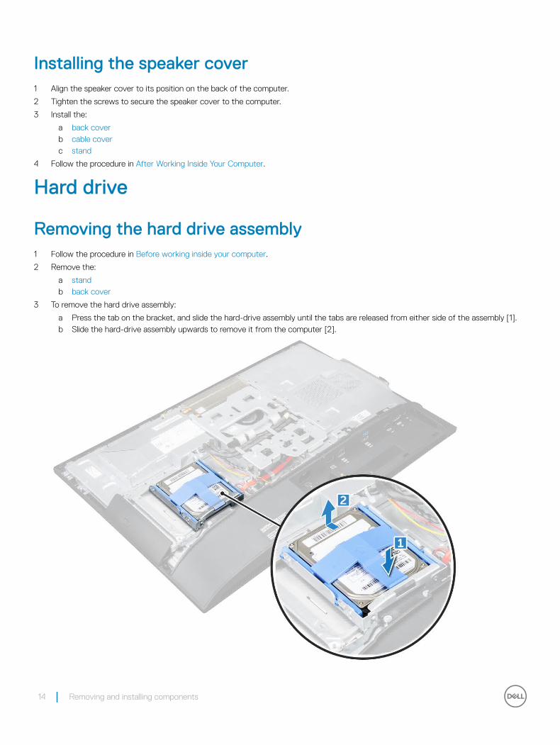
Removing the hard drive assembly1 Follow the procedure in Before working inside your computer.
2 Remove the:
a standb back cover
3 To remove the hard drive assembly:
a Press the tab on the bracket, and slide the hard-drive assembly until the tabs are released from either side of the assembly [1].b Slide the hard-drive assembly upwards to remove it from the computer [2].
14 Removing and installing components
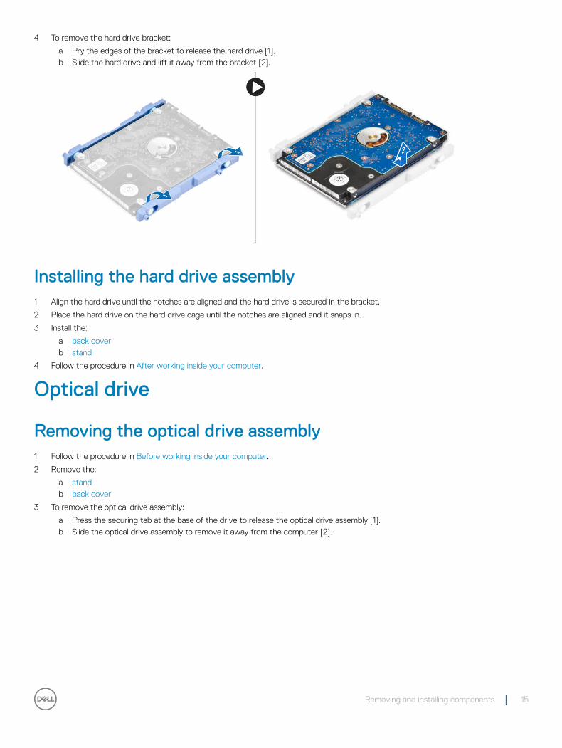
4 To remove the hard drive bracket:
a Pry the edges of the bracket to release the hard drive [1].b Slide the hard drive and lift it away from the bracket [2].
Installing the hard drive assembly1 Align the hard drive until the notches are aligned and the hard drive is secured in the bracket.
2 Place the hard drive on the hard drive cage until the notches are aligned and it snaps in.
3 Install the:
a back coverb stand
4 Follow the procedure in After working inside your computer.
Optical drive
Removing the optical drive assembly1 Follow the procedure in Before working inside your computer.
2 Remove the:
a standb back cover
3 To remove the optical drive assembly:
a Press the securing tab at the base of the drive to release the optical drive assembly [1].b Slide the optical drive assembly to remove it away from the computer [2].
Removing and installing components 15
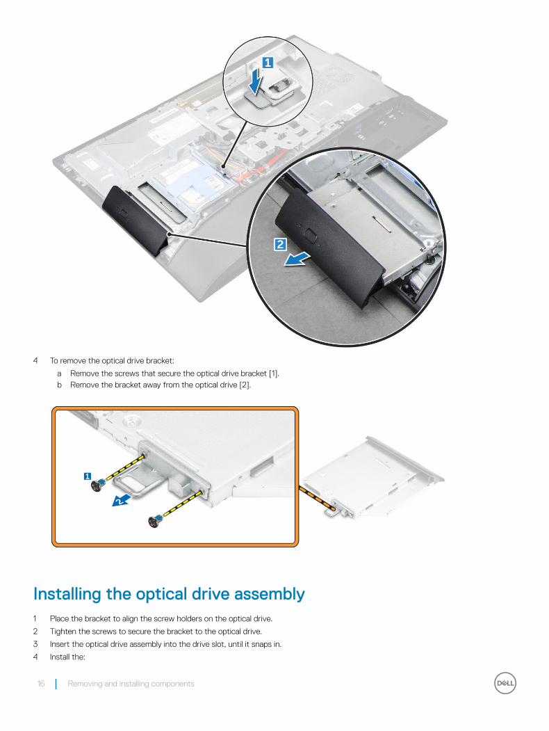
4 To remove the optical drive bracket:
a Remove the screws that secure the optical drive bracket [1].b Remove the bracket away from the optical drive [2].
Installing the optical drive assembly1 Place the bracket to align the screw holders on the optical drive.
2 Tighten the screws to secure the bracket to the optical drive.
3 Insert the optical drive assembly into the drive slot, until it snaps in.
4 Install the:
16 Removing and installing components
a back coverb stand
5 Follow the procedure in After working inside your computer.
System board shield
Removing the system board shield1 Follow the procedure in Before working inside your computer.
2 Remove the:
a standb back cover
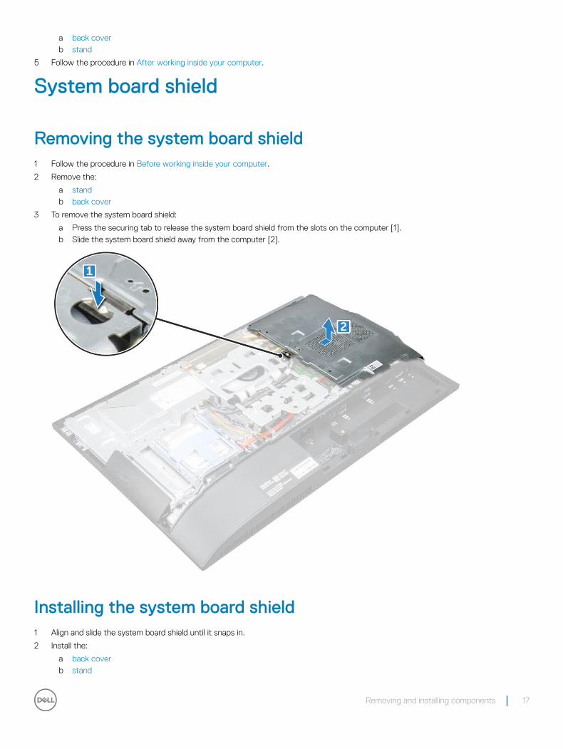
3 To remove the system board shield:
a Press the securing tab to release the system board shield from the slots on the computer [1].b Slide the system board shield away from the computer [2].
Installing the system board shield1 Align and slide the system board shield until it snaps in.
2 Install the:
a back coverb stand
Removing and installing components 17
3 Follow the procedure in After working inside your computer.
Memory module
Removing the memory module1 Follow the procedure in Before working inside your computer.
2 Remove the:
a standb back coverc system board shield
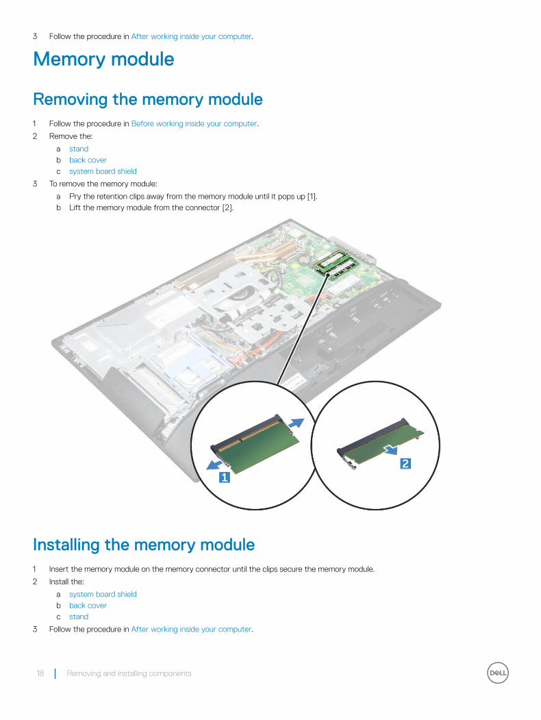
3 To remove the memory module:
a Pry the retention clips away from the memory module until it pops up [1].b Lift the memory module from the connector [2].
Installing the memory module1 Insert the memory module on the memory connector until the clips secure the memory module.
2 Install the:
a system board shieldb back coverc stand
3 Follow the procedure in After working inside your computer.
18 Removing and installing components
Solid State Drive (SSD)
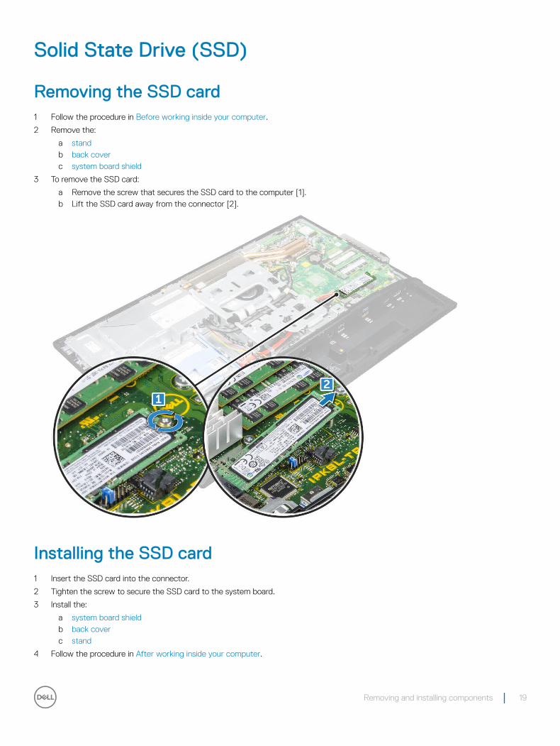
Removing the SSD card1 Follow the procedure in Before working inside your computer.
2 Remove the:
a standb back coverc system board shield
3 To remove the SSD card:
a Remove the screw that secures the SSD card to the computer [1].b Lift the SSD card away from the connector [2].
Installing the SSD card1 Insert the SSD card into the connector.
2 Tighten the screw to secure the SSD card to the system board.
3 Install the:
a system board shieldb back coverc stand
4 Follow the procedure in After working inside your computer.
Removing and installing components 19
Coin cell battery
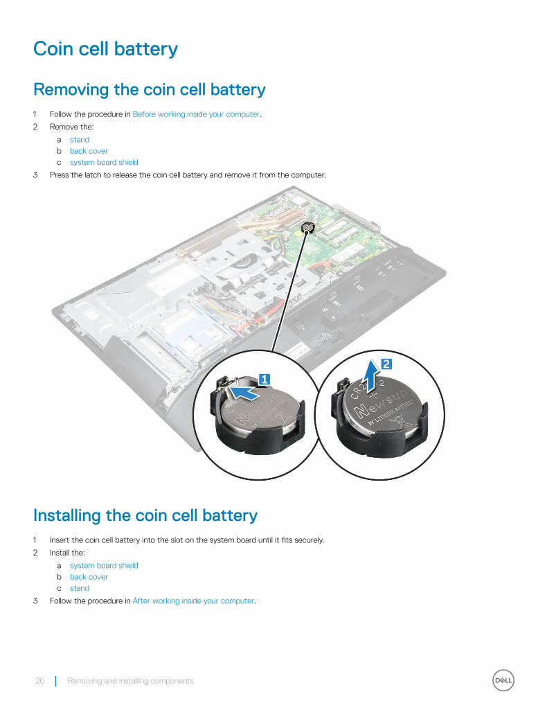
Removing the coin cell battery1 Follow the procedure in Before working inside your computer.
2 Remove the:
a standb back coverc system board shield
3 Press the latch to release the coin cell battery and remove it from the computer.
Installing the coin cell battery1 Insert the coin cell battery into the slot on the system board until it fits securely.
2 Install the:
a system board shieldb back coverc stand
3 Follow the procedure in After working inside your computer.
20 Removing and installing components
WLAN card
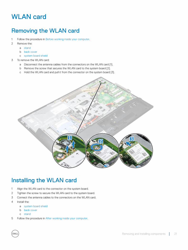
Removing the WLAN card1 Follow the procedure in Before working inside your computer.
2 Remove the:
a standb back coverc system board shield
3 To remove the WLAN card:
a Disconnect the antenna cables from the connectors on the WLAN card [1].b Remove the screw that secures the WLAN card to the system board [2].c Hold the WLAN card and pull it from the connector on the system board [3].
Installing the WLAN card1 Align the WLAN card to the connector on the system board.
2 Tighten the screw to secure the WLAN card to the system board.
3 Connect the antenna cables to the connectors on the WLAN card.
4 Install the:
a system board shieldb back coverc stand
5 Follow the procedure in After working inside your computer.
Removing and installing components 21
Heat sink
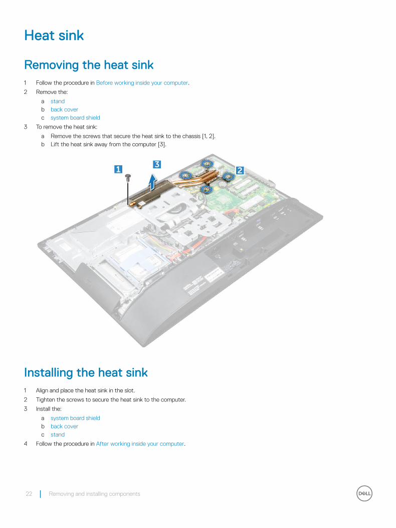
Removing the heat sink 1 Follow the procedure in Before working inside your computer.
2 Remove the:
a standb back coverc system board shield
3 To remove the heat sink:
a Remove the screws that secure the heat sink to the chassis [1, 2].b Lift the heat sink away from the computer [3].
Installing the heat sink1 Align and place the heat sink in the slot.
2 Tighten the screws to secure the heat sink to the computer.
3 Install the:
a system board shieldb back coverc stand
4 Follow the procedure in After working inside your computer.
22 Removing and installing components
Speaker
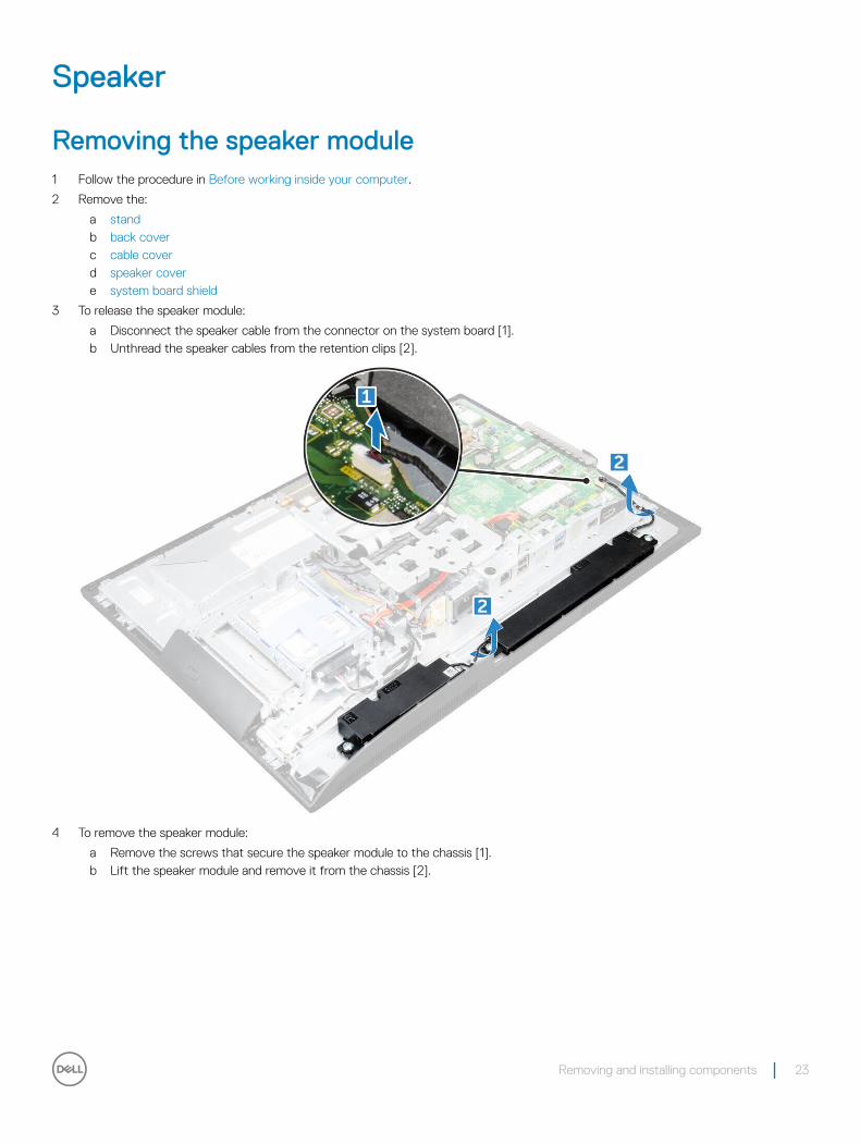
Removing the speaker module1 Follow the procedure in Before working inside your computer.
2 Remove the:
a standb back coverc cable coverd speaker covere system board shield
3 To release the speaker module:
a Disconnect the speaker cable from the connector on the system board [1].b Unthread the speaker cables from the retention clips [2].
4 To remove the speaker module:
a Remove the screws that secure the speaker module to the chassis [1].b Lift the speaker module and remove it from the chassis [2].
Removing and installing components 23
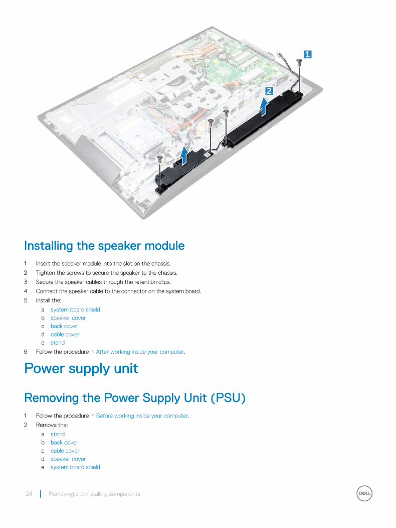
Installing the speaker module1 Insert the speaker module into the slot on the chassis.
2 Tighten the screws to secure the speaker to the chassis.
3 Secure the speaker cables through the retention clips.
4 Connect the speaker cable to the connector on the system board.
5 Install the:
a system board shieldb speaker coverc back coverd cable covere stand
6 Follow the procedure in After working inside your computer.
Power supply unit
Removing the Power Supply Unit (PSU)1 Follow the procedure in Before working inside your computer.
2 Remove the:
a standb back coverc cable coverd speaker covere system board shield
24 Removing and installing components
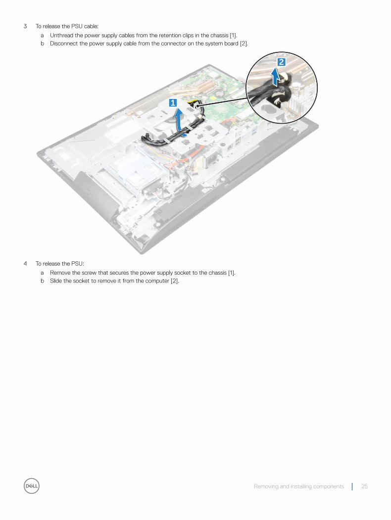
3 To release the PSU cable:
a Unthread the power supply cables from the retention clips in the chassis [1].b Disconnect the power supply cable from the connector on the system board [2].
4 To release the PSU:
a Remove the screw that secures the power supply socket to the chassis [1].b Slide the socket to remove it from the computer [2].
Removing and installing components 25
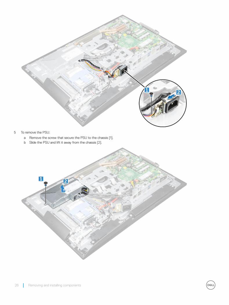
5 To remove the PSU:
a Remove the screw that secure the PSU to the chassis [1].b Slide the PSU and lift it away from the chassis [2].
26 Removing and installing components
Installing the Power Supply Unit (PSU)1 Place the PSU on the chassis.
2 Tighten the screw to secure the PSU to the chassis.
3 Place the power supply socket in the slot on the chassis.
4 Tighten the screw to secure the power supply socket to the chassis.
5 Secure the power supply cable on the retention clips in the chassis.
6 Connect the power supply cables to the connectors on the system board.
7 Install the:
a system board shieldb speaker coverc cable coverd back covere stand
8 Follow the procedure in After working inside your computer.
VESA mount bracket
Removing the VESA mount bracket1 Follow the procedure in Before working inside your computer.
2 Remove the:
a standb back coverc cable coverd speaker covere system board shieldf power supply unit
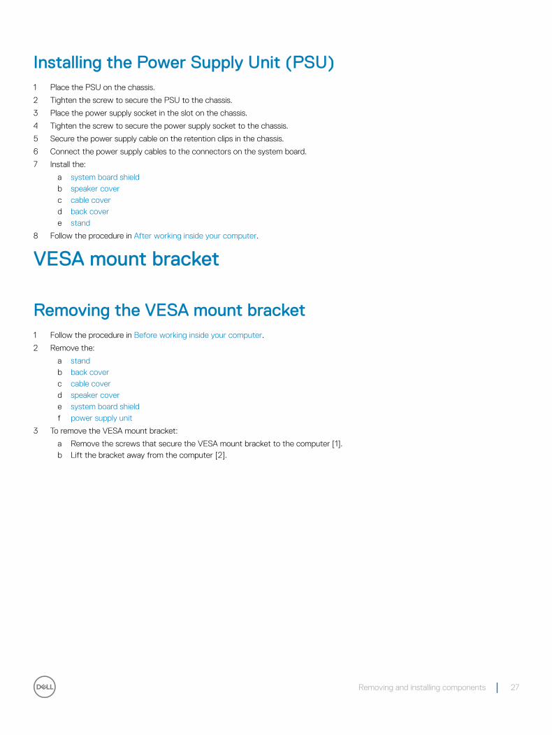
3 To remove the VESA mount bracket:
a Remove the screws that secure the VESA mount bracket to the computer [1].b Lift the bracket away from the computer [2].
Removing and installing components 27
Installing the VESA mount bracket1 Align and place the bracket in the slot on the computer.
2 Tighten the screws that secure the VESA mount bracket to the computer.
3 Install the:
a power supply unitb system board shieldc speaker coverd cable covere back coverf stand
4 Follow the procedure in After working inside your computer.
Converter board
Removing the converter board1 Follow the procedure in Before working inside your computer.
2 Remove the:
a standb back coverc cable coverd speaker covere system board shieldf power supply unit
28 Removing and installing components
g VESA mount bracket
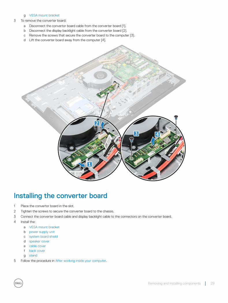
3 To remove the converter board:
a Disconnect the convertor board cable from the converter board [1].b Disconnect the display backlight cable from the converter board [2].c Remove the screws that secure the converter board to the computer [3].d Lift the converter board away from the computer [4].
Installing the converter board1 Place the convertor board in the slot.
2 Tighten the screws to secure the converter board to the chassis.
3 Connect the converter board cable and display backlight cable to the connectors on the converter board.
4 Install the:
a VESA mount bracketb power supply unitc system board shieldd speaker covere cable coverf back coverg stand
5 Follow the procedure in After working inside your computer.
Removing and installing components 29
System fan
Removing the system fan1 Follow the procedure in Before working inside your computer.
2 Remove the:
a standb back coverc cable coverd speaker covere system board shieldf power supply unitg VESA mount bracket
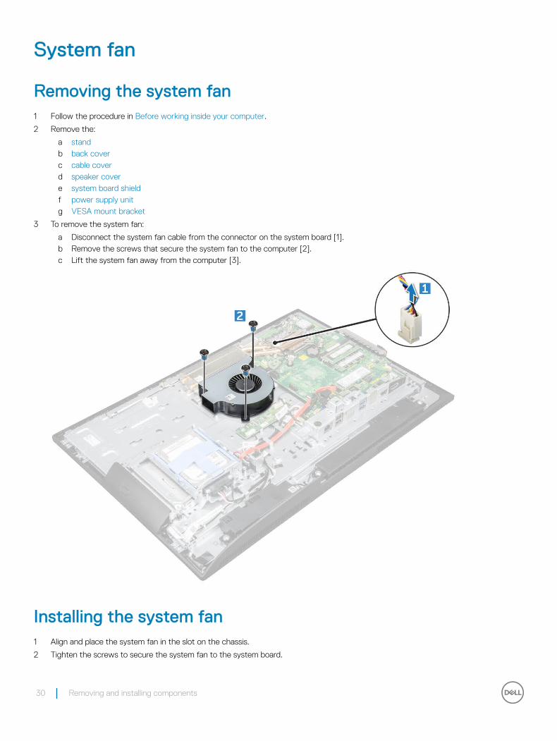
3 To remove the system fan:
a Disconnect the system fan cable from the connector on the system board [1].b Remove the screws that secure the system fan to the computer [2].c Lift the system fan away from the computer [3].
Installing the system fan1 Align and place the system fan in the slot on the chassis.
2 Tighten the screws to secure the system fan to the system board.
30 Removing and installing components
3 Connect the system fan cable to the connector on the system board.
4 Install the:a VESA mount bracketb power supply unitc system board shieldd speaker covere cable coverf back coverg stand
5 Follow the procedure in After working inside your computer.
Intrusion switch
Removing the intrusion switch1 Follow the procedure in Before working inside your computer.
2 Remove the:a standb back coverc cable coverd speaker covere system board shieldf power supply unitg VESA mount bracket
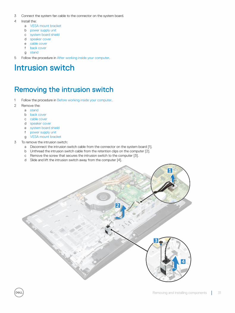
3 To remove the intrusion switch:a Disconnect the intrusion switch cable from the connector on the system board [1].b Unthread the intrusion switch cable from the retention clips on the computer [2].c Remove the screw that secures the intrusion switch to the computer [3].d Slide and lift the intrusion switch away from the computer [4].
Removing and installing components 31
Installing the intrusion switch1 Place the intrusion switch in the slot on the computer.
2 Tighten the screw to secure the intrusion switch to the chassis.
3 Route intrusion switch cable along the retention clips on the chassis.
4 Connect the intrusion switch cable to the connector on the system board.
5 Install:
a VESA mount bracketb power supply unitc system board shieldd speaker covere cable coverf back coverg stand
6 Follow the procedures in After working inside your computer.
Power and On-Screen Display (OSD) buttons board
Removing the power and On-Screen Display (OSD) buttons board1 Follow the procedure in Before working inside your computer.
2 Remove the:
a standb back cover
3 To remove the power and OSD buttons board:
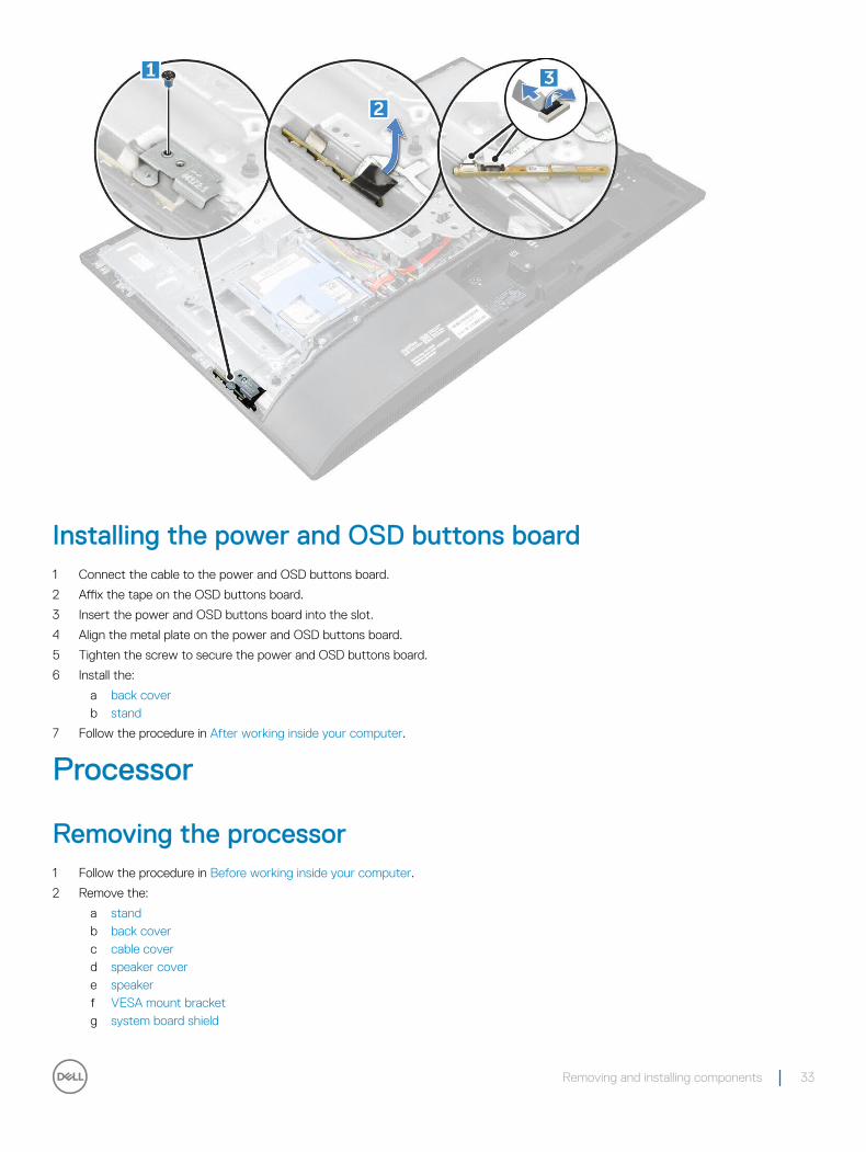
a Remove the screw to remove the metal plate that secures the power and OSD buttons board to the computer [1].b Peel off the tape from the OSD buttons board [2].c Remove the power and OSD buttons board from the chassis.d Disconnect the cables from the power and OSD buttons board to release the board from the computer [3].
32 Removing and installing components
Installing the power and OSD buttons board1 Connect the cable to the power and OSD buttons board.
2 Affix the tape on the OSD buttons board.
3 Insert the power and OSD buttons board into the slot.
4 Align the metal plate on the power and OSD buttons board.
5 Tighten the screw to secure the power and OSD buttons board.
6 Install the:
a back coverb stand
7 Follow the procedure in After working inside your computer.
Processor
Removing the processor1 Follow the procedure in Before working inside your computer.
2 Remove the:
a standb back coverc cable coverd speaker covere speakerf VESA mount bracketg system board shield
Removing and installing components 33
h SSD cardi WLAN cardj memoryk heat sinkl system fan
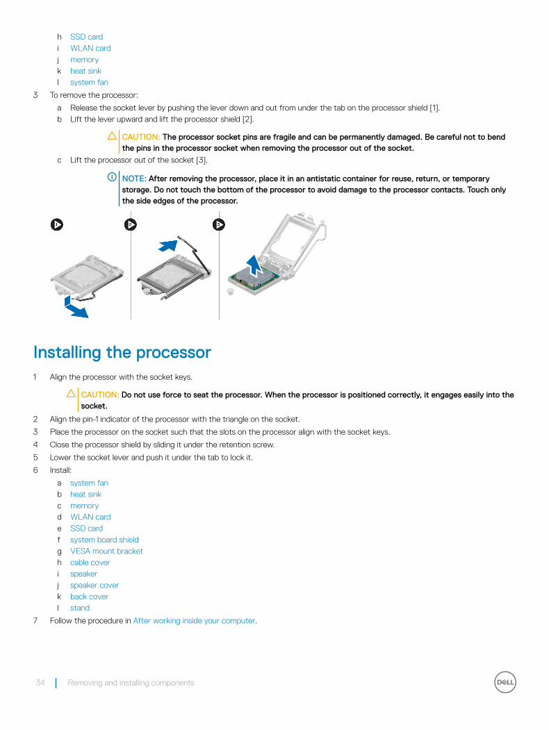
3 To remove the processor:
a Release the socket lever by pushing the lever down and out from under the tab on the processor shield [1].b Lift the lever upward and lift the processor shield [2].
CAUTION: The processor socket pins are fragile and can be permanently damaged. Be careful not to bend the pins in the processor socket when removing the processor out of the socket.
c Lift the processor out of the socket [3].
NOTE: After removing the processor, place it in an antistatic container for reuse, return, or temporary storage. Do not touch the bottom of the processor to avoid damage to the processor contacts. Touch only the side edges of the processor.
Installing the processor1 Align the processor with the socket keys.
CAUTION: Do not use force to seat the processor. When the processor is positioned correctly, it engages easily into the socket.
2 Align the pin-1 indicator of the processor with the triangle on the socket.
3 Place the processor on the socket such that the slots on the processor align with the socket keys.
4 Close the processor shield by sliding it under the retention screw.
5 Lower the socket lever and push it under the tab to lock it.
6 Install:
a system fanb heat sinkc memoryd WLAN carde SSD cardf system board shieldg VESA mount bracketh cable coveri speakerj speaker coverk back coverl stand
7 Follow the procedure in After working inside your computer.
34 Removing and installing components
System board
Removing the system board1 Follow the procedure in Before working inside your computer.
2 Remove the:
a standb back coverc cable coverd speaker covere speakerf hard driveg optical driveh VESA mount bracketi system board shieldj SSD cardk WLAN cardl memorym heat sinkn system fano processorp coin cell batteryq power supply unit
3 Disconnect the following cables from the system board:
a display [1]b system fan [2]c SATA [3]d intrusion switch [4]e hard drive and optical drive [5]f speaker [6]g camera and microphone [7]
Removing and installing components 35
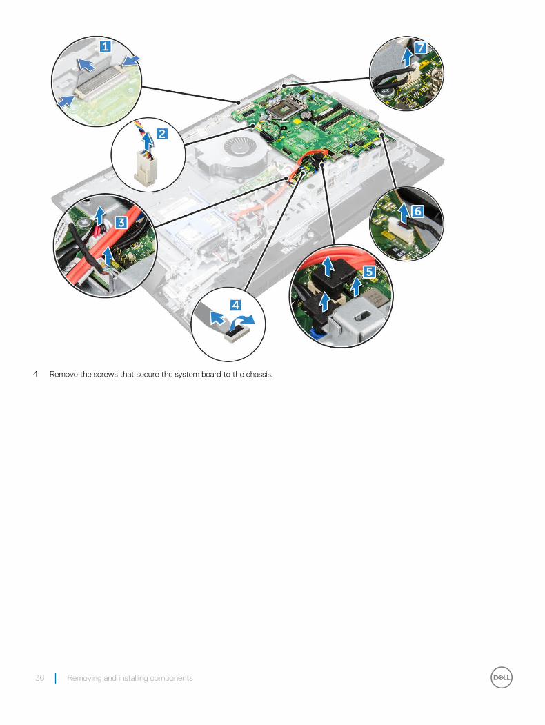
4 Remove the screws that secure the system board to the chassis.
36 Removing and installing components
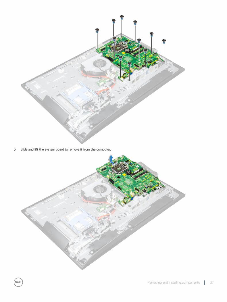
5 Slide and lift the system board to remove it from the computer.
Removing and installing components 37
Installing the system board1 Place the system board on the computer.
2 Connect all the cables to the system board.
3 Tighten the screws to secure the system board to the base panel.
4 Install the:
a power supply unitb coin cell batteryc system fand processore heat sinkf memoryg WLAN cardh SSD cardi system board shieldj VESA mount bracketk optical drivel hard drivem cable covern speakero speaker coverp back coverq stand
5 Follow the procedure in After working inside your computer.
38 Removing and installing components
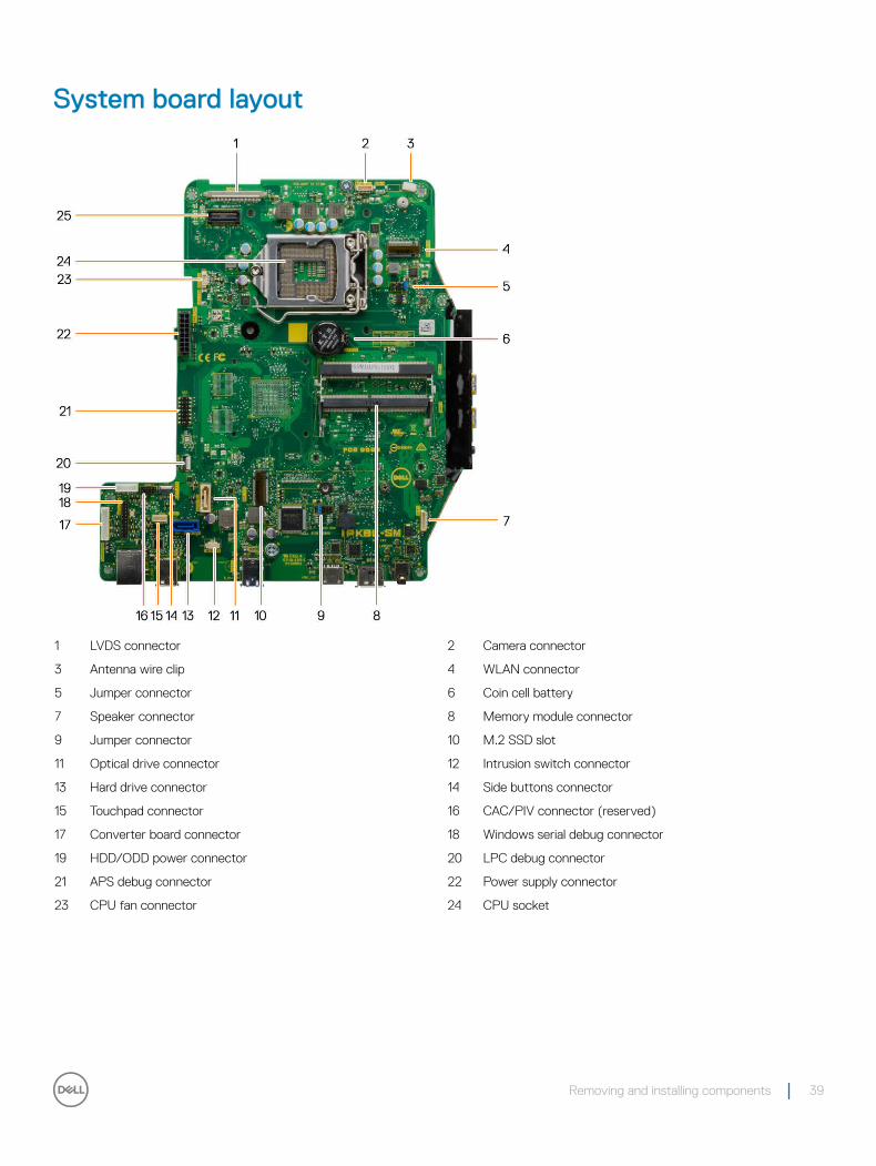
System board layout
1 LVDS connector 2 Camera connector
3 Antenna wire clip 4 WLAN connector
5 Jumper connector 6 Coin cell battery
7 Speaker connector 8 Memory module connector
9 Jumper connector 10 M.2 SSD slot
11 Optical drive connector 12 Intrusion switch connector
13 Hard drive connector 14 Side buttons connector
15 Touchpad connector 16 CAC/PIV connector (reserved)
17 Converter board connector 18 Windows serial debug connector
19 HDD/ODD power connector 20 LPC debug connector
21 APS debug connector 22 Power supply connector
23 CPU fan connector 24 CPU socket
Removing and installing components 39
Technology and components
This chapter details the technology and components available in the systems.
Topics:
• Processors• Chipsets• Storage options• Memory configurations• DDR4
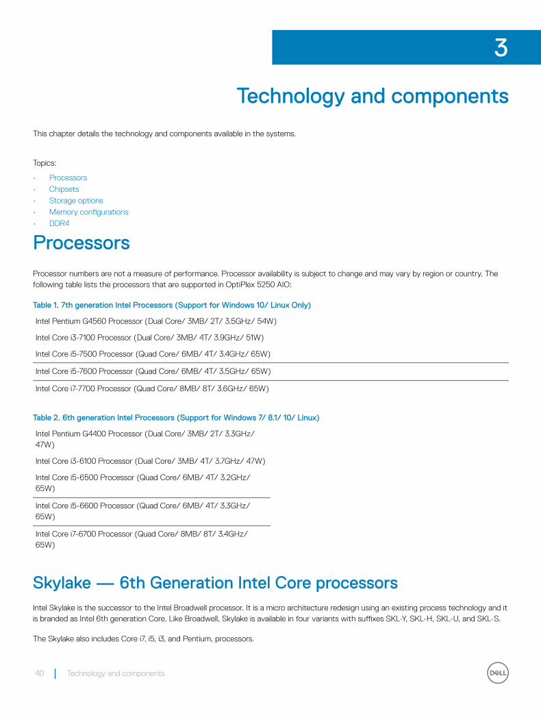
ProcessorsProcessor numbers are not a measure of performance. Processor availability is subject to change and may vary by region or country. The following table lists the processors that are supported in OptiPlex 5250 AIO:
Table 1. 7th generation Intel Processors (Support for Windows 10/ Linux Only)
Intel Pentium G4560 Processor (Dual Core/ 3MB/ 2T/ 3.5GHz/ 54W)
Intel Core i3-7100 Processor (Dual Core/ 3MB/ 4T/ 3.9GHz/ 51W)
Intel Core i5-7500 Processor (Quad Core/ 6MB/ 4T/ 3.4GHz/ 65W)
Intel Core i5-7600 Processor (Quad Core/ 6MB/ 4T/ 3.5GHz/ 65W)
Intel Core i7-7700 Processor (Quad Core/ 8MB/ 8T/ 3.6GHz/ 65W)
Table 2. 6th generation Intel Processors (Support for Windows 7/ 8.1/ 10/ Linux)
Intel Pentium G4400 Processor (Dual Core/ 3MB/ 2T/ 3.3GHz/ 47W)
Intel Core i3-6100 Processor (Dual Core/ 3MB/ 4T/ 3.7GHz/ 47W)
Intel Core i5-6500 Processor (Quad Core/ 6MB/ 4T/ 3.2GHz/ 65W)
Intel Core i5-6600 Processor (Quad Core/ 6MB/ 4T/ 3.3GHz/ 65W)
Intel Core i7-6700 Processor (Quad Core/ 8MB/ 8T/ 3.4GHz/ 65W)
Skylake — 6th Generation Intel Core processorsIntel Skylake is the successor to the Intel Broadwell processor. It is a micro architecture redesign using an existing process technology and it is branded as Intel 6th generation Core. Like Broadwell, Skylake is available in four variants with suffixes SKL-Y, SKL-H, SKL-U, and SKL-S.
The Skylake also includes Core i7, i5, i3, and Pentium, processors.
3
40 Technology and components
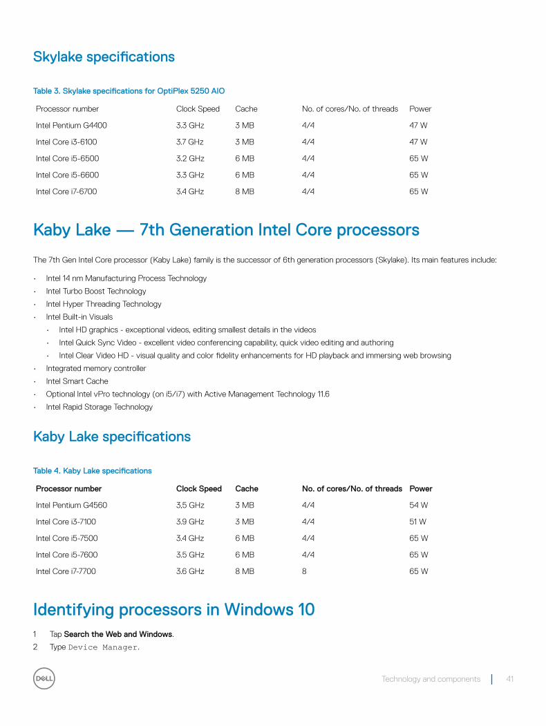
Skylake specifications
Table 3. Skylake specifications for OptiPlex 5250 AIO
Processor number Clock Speed Cache No. of cores/No. of threads Power
Intel Pentium G4400 3.3 GHz 3 MB 4/4 47 W
Intel Core i3-6100 3.7 GHz 3 MB 4/4 47 W
Intel Core i5-6500 3.2 GHz 6 MB 4/4 65 W
Intel Core i5-6600 3.3 GHz 6 MB 4/4 65 W
Intel Core i7-6700 3.4 GHz 8 MB 4/4 65 W
Kaby Lake — 7th Generation Intel Core processors
The 7th Gen Intel Core processor (Kaby Lake) family is the successor of 6th generation processors (Skylake). Its main features include:
• Intel 14 nm Manufacturing Process Technology
• Intel Turbo Boost Technology
• Intel Hyper Threading Technology
• Intel Built-in Visuals
• Intel HD graphics - exceptional videos, editing smallest details in the videos
• Intel Quick Sync Video - excellent video conferencing capability, quick video editing and authoring
• Intel Clear Video HD - visual quality and color fidelity enhancements for HD playback and immersing web browsing
• Integrated memory controller
• Intel Smart Cache
• Optional Intel vPro technology (on i5/i7) with Active Management Technology 11.6
• Intel Rapid Storage Technology
Kaby Lake specifications
Table 4. Kaby Lake specifications
Processor number Clock Speed Cache No. of cores/No. of threads Power
Intel Pentium G4560 3,5 GHz 3 MB 4/4 54 W
Intel Core i3-7100 3.9 GHz 3 MB 4/4 51 W
Intel Core i5-7500 3.4 GHz 6 MB 4/4 65 W
Intel Core i5-7600 3.5 GHz 6 MB 4/4 65 W
Intel Core i7-7700 3.6 GHz 8 MB 8 65 W
Identifying processors in Windows 101 Tap Search the Web and Windows.
2 Type Device Manager.
Technology and components 41
3 Tap Processor.
Identifying processors in Windows 71 Click Start > Control Panel > Device Manager.
2 Select Processor.
ChipsetsAll laptops or notebook communicate with the CPU through the chipset. This laptop is shipped with the Intel 100 Series chipset .
Identifying the chipset in Device Manager on Windows 10
1 Click All Settings on the Windows 10 Charms Bar.
2 From the Control Panel, select Device Manager.
3 Expand System Devices and search for the chipset.
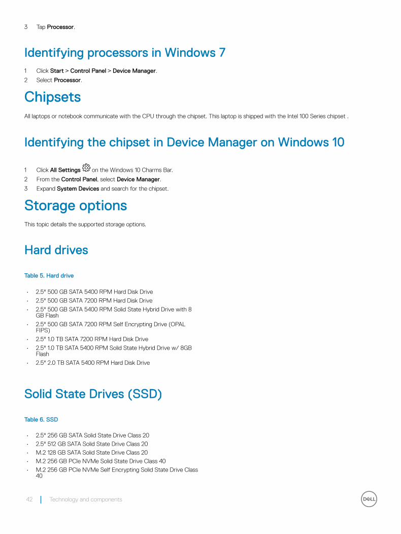
Storage optionsThis topic details the supported storage options.
Hard drives
Table 5. Hard drive
• 2.5" 500 GB SATA 5400 RPM Hard Disk Drive
• 2.5" 500 GB SATA 7200 RPM Hard Disk Drive
• 2.5" 500 GB SATA 5400 RPM Solid State Hybrid Drive with 8 GB Flash
• 2.5" 500 GB SATA 7200 RPM Self Encrypting Drive (OPAL FIPS)
• 2.5" 1.0 TB SATA 7200 RPM Hard Disk Drive
• 2.5" 1.0 TB SATA 5400 RPM Solid State Hybrid Drive w/ 8GB Flash
• 2.5" 2.0 TB SATA 5400 RPM Hard Disk Drive
Solid State Drives (SSD)
Table 6. SSD
• 2.5" 256 GB SATA Solid State Drive Class 20
• 2.5" 512 GB SATA Solid State Drive Class 20
• M.2 128 GB SATA Solid State Drive Class 20
• M.2 256 GB PCIe NVMe Solid State Drive Class 40
• M.2 256 GB PCIe NVMe Self Encrypting Solid State Drive Class 40
42 Technology and components
• M.2 512 GB PCIe NVMe Solid State DriveClass 40
• M.2 1 TB PCIe NVMe Solid State Drive Class 40
Identifying the hard drive in Windows 10
1 Click All Settings on the Windows 10 Charms Bar.
2 Click Control Panel, select Device Manager, and expand Disk drives.
The hard drive is listed under Disk drives.
Entering BIOS setup1 Turn on or restart your laptop.
2 When the Dell logo appears, perform one of the following actions to enter the BIOS setup program:
• With keyboard — Tap F2 until the Entering BIOS setup message appears. To enter the Boot selection menu, tap F12.
Hard drive is listed under the System Information under the General group.
Memory configurationsThe supported memory configurations for are as follows:
• 2GB DDR4, 2400MHz, (1 x 2GB)- Linux operating system only
• 4GB DDR4, 2400MHz, (1 x 4GB)
• 8GB DDR4, 2400MHz, (1 x 8GB)
• 8GB DDR4, 2400MHz, (2 x 4GB)
• 16GB DDR4, 2400MHz, (2 x 8GB)
• 32GB DDR4, 2400MHz, (2 x 16GB)
NOTE: If this computer is purchased with Intel 6th Generation CPUs, the maximum MHz the computer can achieve is 2133.
Verifying system memory in Windows 10 and Windows 7
Windows 10
1 Click the Windows button and select All Settings > System.
2 Under System, click About.
Windows 7
• Click Start → Control Panel → System.
Technology and components 43
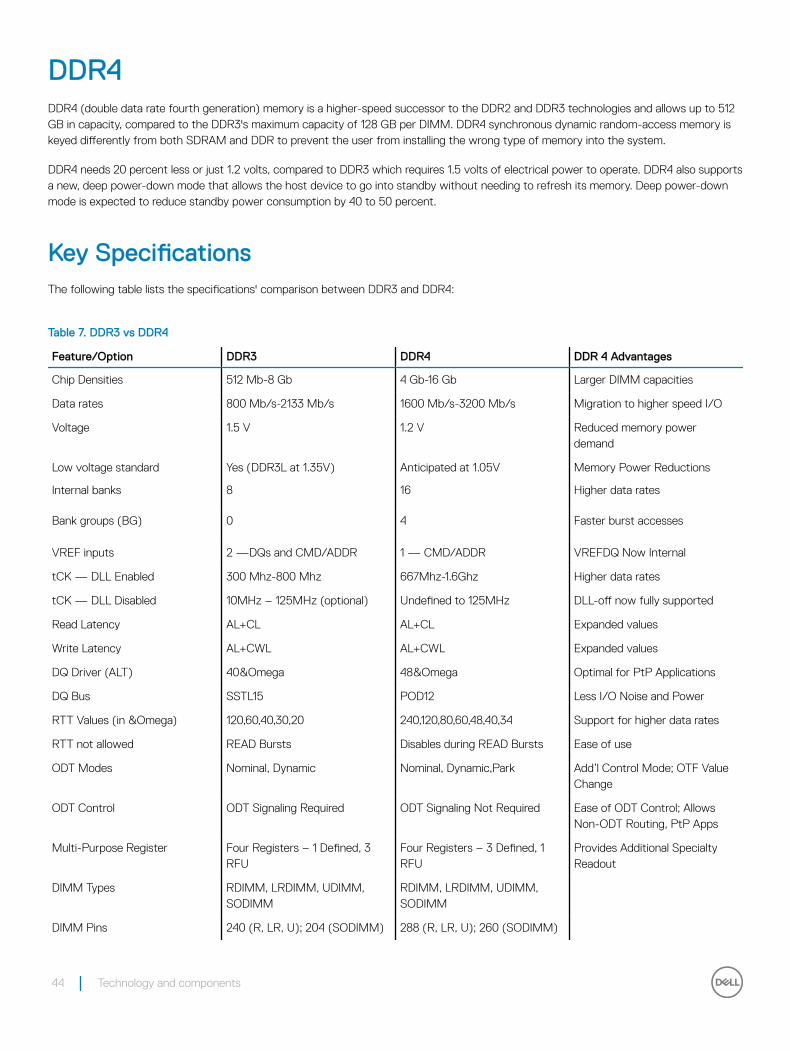
DDR4DDR4 (double data rate fourth generation) memory is a higher-speed successor to the DDR2 and DDR3 technologies and allows up to 512 GB in capacity, compared to the DDR3's maximum capacity of 128 GB per DIMM. DDR4 synchronous dynamic random-access memory is keyed differently from both SDRAM and DDR to prevent the user from installing the wrong type of memory into the system.
DDR4 needs 20 percent less or just 1.2 volts, compared to DDR3 which requires 1.5 volts of electrical power to operate. DDR4 also supports a new, deep power-down mode that allows the host device to go into standby without needing to refresh its memory. Deep power-down mode is expected to reduce standby power consumption by 40 to 50 percent.
Key SpecificationsThe following table lists the specifications' comparison between DDR3 and DDR4:
Table 7. DDR3 vs DDR4
Feature/Option DDR3 DDR4 DDR 4 Advantages
Chip Densities 512 Mb-8 Gb 4 Gb-16 Gb Larger DIMM capacities
Data rates 800 Mb/s-2133 Mb/s 1600 Mb/s-3200 Mb/s Migration to higher speed I/O
Voltage 1.5 V 1.2 V Reduced memory power demand
Low voltage standard Yes (DDR3L at 1.35V) Anticipated at 1.05V Memory Power Reductions
Internal banks 8 16 Higher data rates
Bank groups (BG) 0 4 Faster burst accesses
VREF inputs 2 —DQs and CMD/ADDR 1 — CMD/ADDR VREFDQ Now Internal
tCK — DLL Enabled 300 Mhz-800 Mhz 667Mhz-1.6Ghz Higher data rates
tCK — DLL Disabled 10MHz – 125MHz (optional) Undefined to 125MHz DLL-off now fully supported
Read Latency AL+CL AL+CL Expanded values
Write Latency AL+CWL AL+CWL Expanded values
DQ Driver (ALT) 40&Omega 48&Omega Optimal for PtP Applications
DQ Bus SSTL15 POD12 Less I/O Noise and Power
RTT Values (in &Omega) 120,60,40,30,20 240,120,80,60,48,40,34 Support for higher data rates
RTT not allowed READ Bursts Disables during READ Bursts Ease of use
ODT Modes Nominal, Dynamic Nominal, Dynamic,Park Add’l Control Mode; OTF Value Change
ODT Control ODT Signaling Required ODT Signaling Not Required Ease of ODT Control; Allows Non-ODT Routing, PtP Apps
Multi-Purpose Register Four Registers – 1 Defined, 3 RFU
Four Registers – 3 Defined, 1 RFU
Provides Additional Specialty Readout
DIMM Types RDIMM, LRDIMM, UDIMM, SODIMM
RDIMM, LRDIMM, UDIMM, SODIMM
DIMM Pins 240 (R, LR, U); 204 (SODIMM) 288 (R, LR, U); 260 (SODIMM)
44 Technology and components
Feature/Option DDR3 DDR4 DDR 4 Advantages
RAS ECC CRC, Parity, Addressability, GDM More RAS features; improved data integrity
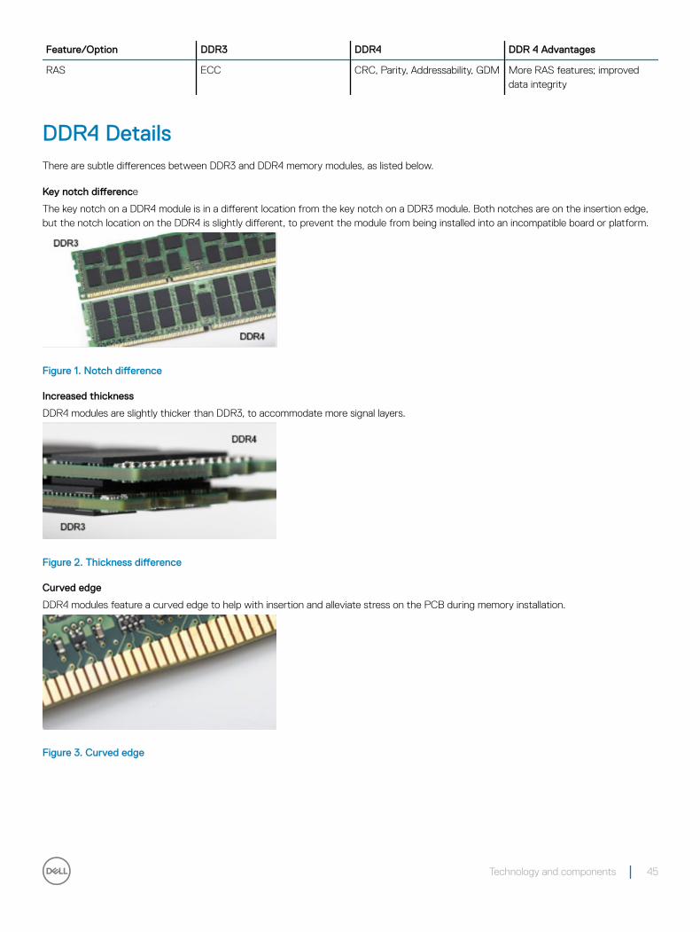
DDR4 DetailsThere are subtle differences between DDR3 and DDR4 memory modules, as listed below.
Key notch difference
The key notch on a DDR4 module is in a different location from the key notch on a DDR3 module. Both notches are on the insertion edge, but the notch location on the DDR4 is slightly different, to prevent the module from being installed into an incompatible board or platform.
Figure 1. Notch difference
Increased thickness
DDR4 modules are slightly thicker than DDR3, to accommodate more signal layers.
Figure 2. Thickness difference
Curved edge
DDR4 modules feature a curved edge to help with insertion and alleviate stress on the PCB during memory installation.
Figure 3. Curved edge
Technology and components 45
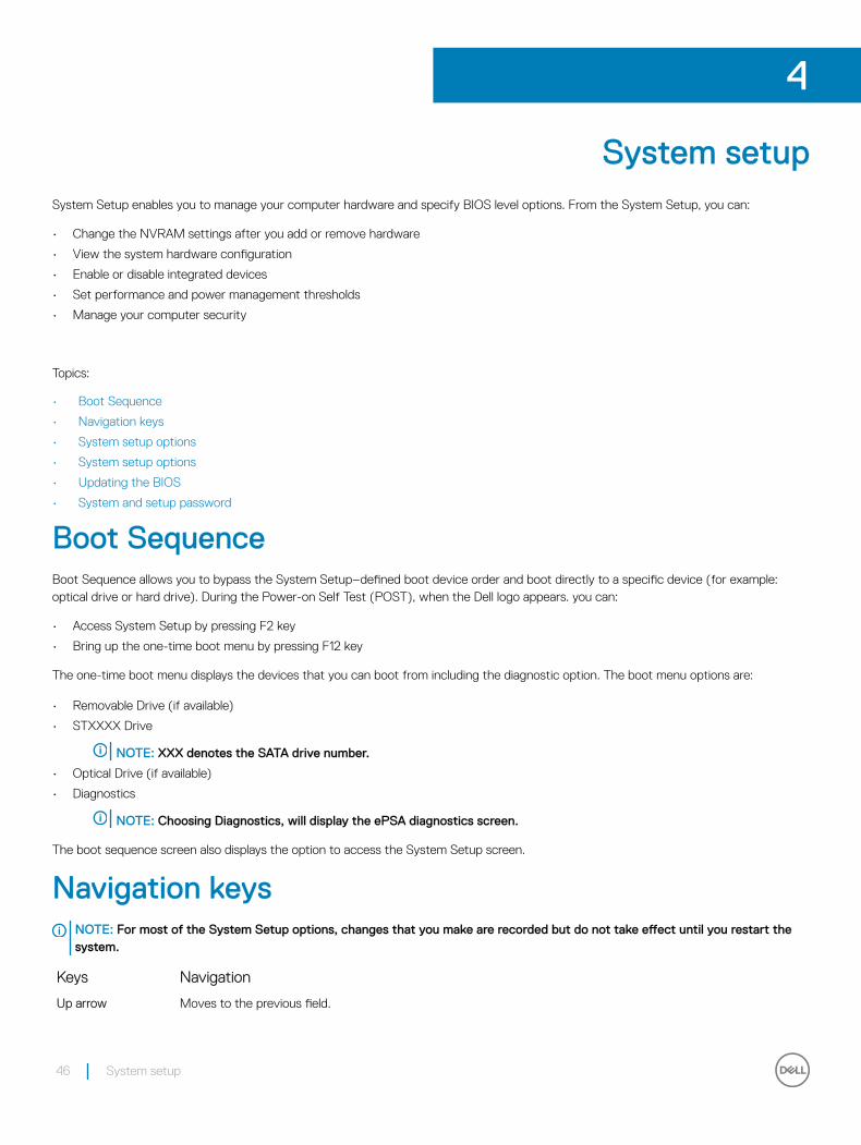
System setupSystem Setup enables you to manage your computer hardware and specify BIOS level options. From the System Setup, you can:
• Change the NVRAM settings after you add or remove hardware
• View the system hardware configuration
• Enable or disable integrated devices
• Set performance and power management thresholds
• Manage your computer security
Topics:
• Boot Sequence
• Navigation keys
• System setup options
• System setup options
• Updating the BIOS
• System and setup password
Boot SequenceBoot Sequence allows you to bypass the System Setup–defined boot device order and boot directly to a specific device (for example: optical drive or hard drive). During the Power-on Self Test (POST), when the Dell logo appears. you can:
• Access System Setup by pressing F2 key
• Bring up the one-time boot menu by pressing F12 key
The one-time boot menu displays the devices that you can boot from including the diagnostic option. The boot menu options are:
• Removable Drive (if available)
• STXXXX Drive
NOTE: XXX denotes the SATA drive number.
• Optical Drive (if available)
• Diagnostics
NOTE: Choosing Diagnostics, will display the ePSA diagnostics screen.
The boot sequence screen also displays the option to access the System Setup screen.
Navigation keysNOTE: For most of the System Setup options, changes that you make are recorded but do not take effect until you restart the system.
Keys Navigation
Up arrow Moves to the previous field.
4
46 System setup
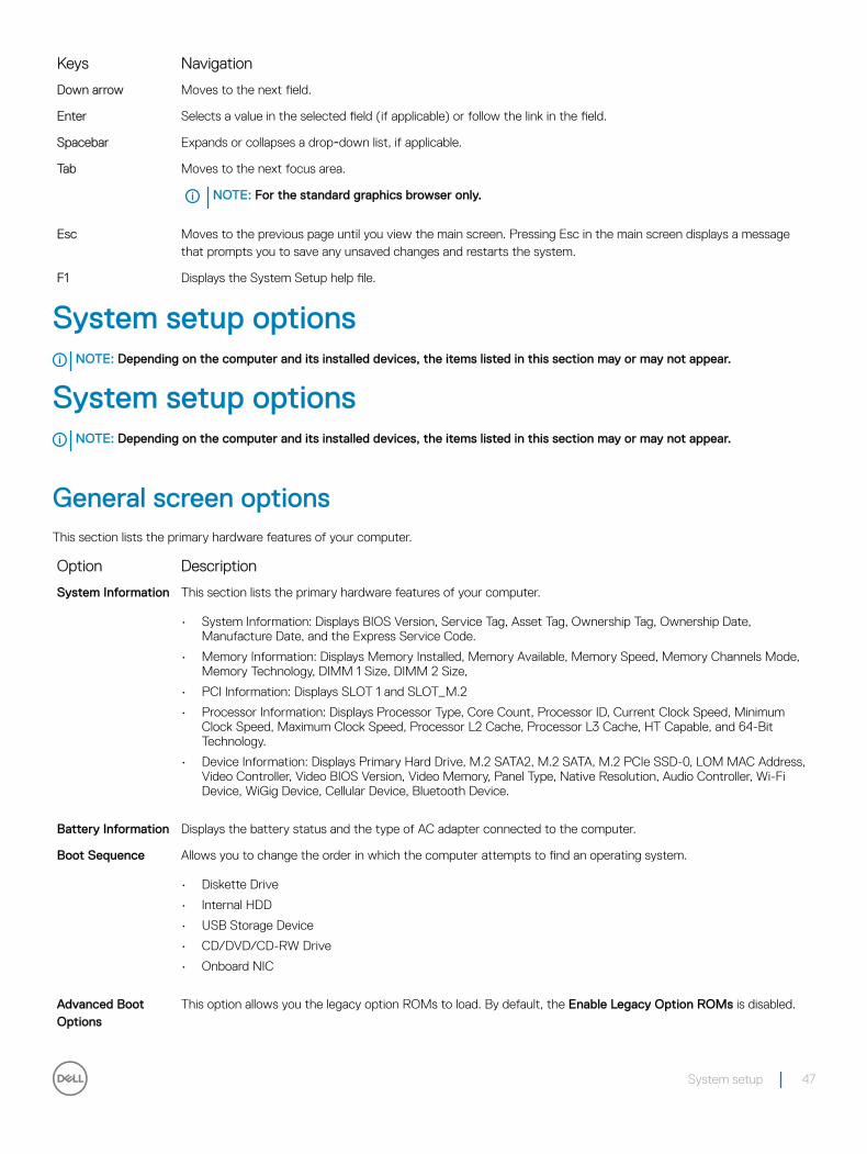
Keys Navigation
Down arrow Moves to the next field.
Enter Selects a value in the selected field (if applicable) or follow the link in the field.
Spacebar Expands or collapses a drop‐down list, if applicable.
Tab Moves to the next focus area.
NOTE: For the standard graphics browser only.
Esc Moves to the previous page until you view the main screen. Pressing Esc in the main screen displays a message that prompts you to save any unsaved changes and restarts the system.
F1 Displays the System Setup help file.
System setup optionsNOTE: Depending on the computer and its installed devices, the items listed in this section may or may not appear.
System setup optionsNOTE: Depending on the computer and its installed devices, the items listed in this section may or may not appear.
General screen optionsThis section lists the primary hardware features of your computer.
Option Description
System Information This section lists the primary hardware features of your computer.
• System Information: Displays BIOS Version, Service Tag, Asset Tag, Ownership Tag, Ownership Date, Manufacture Date, and the Express Service Code.
• Memory Information: Displays Memory Installed, Memory Available, Memory Speed, Memory Channels Mode, Memory Technology, DIMM 1 Size, DIMM 2 Size,
• PCI Information: Displays SLOT 1 and SLOT_M.2
• Processor Information: Displays Processor Type, Core Count, Processor ID, Current Clock Speed, Minimum Clock Speed, Maximum Clock Speed, Processor L2 Cache, Processor L3 Cache, HT Capable, and 64-Bit Technology.
• Device Information: Displays Primary Hard Drive, M.2 SATA2, M.2 SATA, M.2 PCIe SSD-0, LOM MAC Address, Video Controller, Video BIOS Version, Video Memory, Panel Type, Native Resolution, Audio Controller, Wi-Fi Device, WiGig Device, Cellular Device, Bluetooth Device.
Battery Information Displays the battery status and the type of AC adapter connected to the computer.
Boot Sequence Allows you to change the order in which the computer attempts to find an operating system.
• Diskette Drive
• Internal HDD
• USB Storage Device
• CD/DVD/CD-RW Drive
• Onboard NIC
Advanced Boot Options
This option allows you the legacy option ROMs to load. By default, the Enable Legacy Option ROMs is disabled.
System setup 47
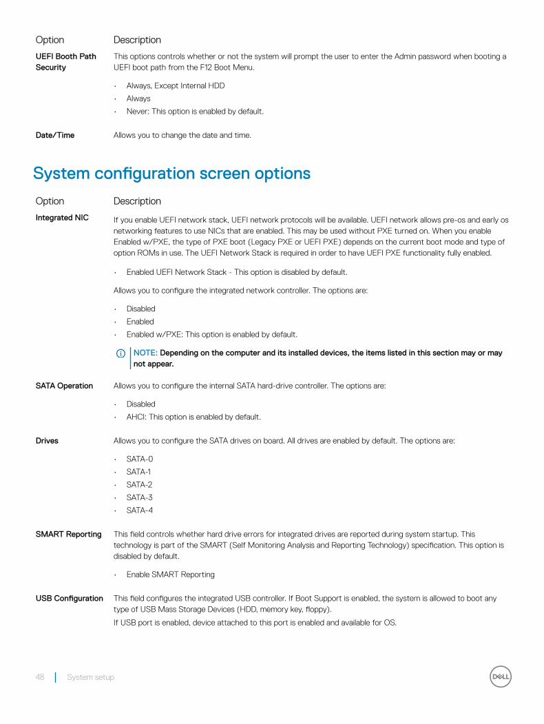
Option Description
UEFI Booth Path Security
This options controls whether or not the system will prompt the user to enter the Admin password when booting a UEFI boot path from the F12 Boot Menu.
• Always, Except Internal HDD
• Always
• Never: This option is enabled by default.
Date/Time Allows you to change the date and time.
System configuration screen options
Option Description
Integrated NIC If you enable UEFI network stack, UEFI network protocols will be available. UEFI network allows pre-os and early os networking features to use NICs that are enabled. This may be used without PXE turned on. When you enable Enabled w/PXE, the type of PXE boot (Legacy PXE or UEFI PXE) depends on the current boot mode and type of option ROMs in use. The UEFI Network Stack is required in order to have UEFI PXE functionality fully enabled.
• Enabled UEFI Network Stack - This option is disabled by default.
Allows you to configure the integrated network controller. The options are:
• Disabled
• Enabled
• Enabled w/PXE: This option is enabled by default.
NOTE: Depending on the computer and its installed devices, the items listed in this section may or may not appear.
SATA Operation Allows you to configure the internal SATA hard-drive controller. The options are:
• Disabled
• AHCI: This option is enabled by default.
Drives Allows you to configure the SATA drives on board. All drives are enabled by default. The options are:
• SATA-0
• SATA-1
• SATA-2
• SATA-3
• SATA-4
SMART Reporting This field controls whether hard drive errors for integrated drives are reported during system startup. This technology is part of the SMART (Self Monitoring Analysis and Reporting Technology) specification. This option is disabled by default.
• Enable SMART Reporting
USB Configuration This field configures the integrated USB controller. If Boot Support is enabled, the system is allowed to boot any type of USB Mass Storage Devices (HDD, memory key, floppy).
If USB port is enabled, device attached to this port is enabled and available for OS.
48 System setup
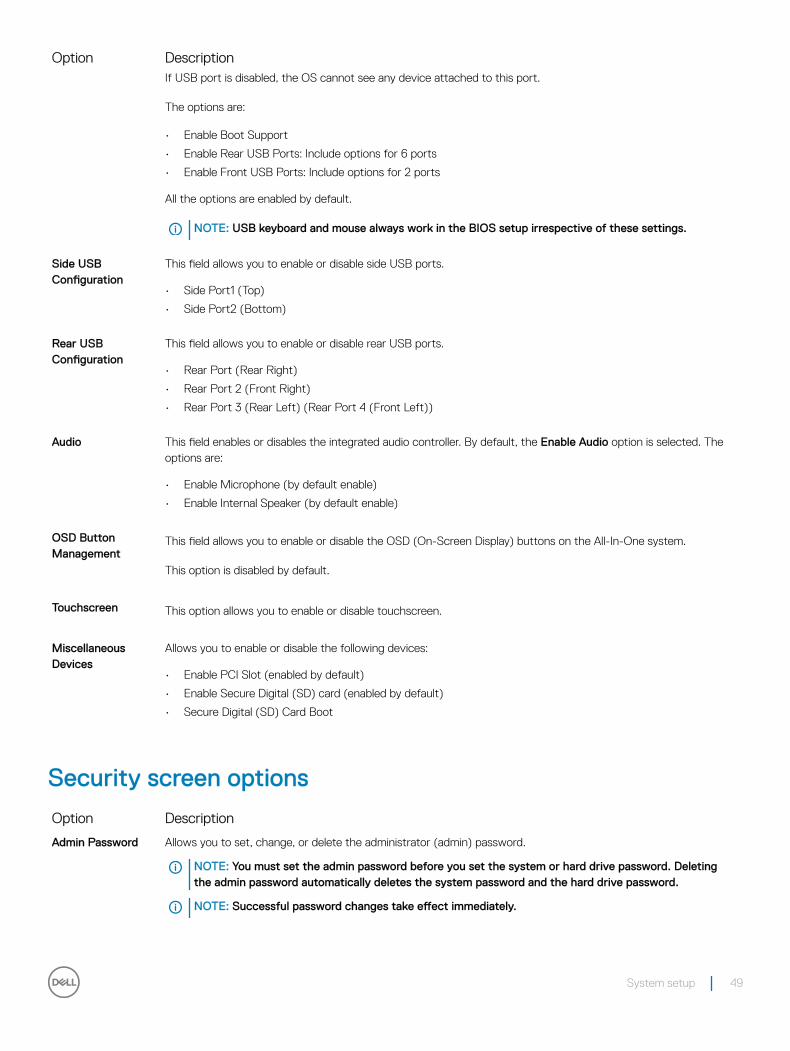
Option DescriptionIf USB port is disabled, the OS cannot see any device attached to this port.
The options are:
• Enable Boot Support
• Enable Rear USB Ports: Include options for 6 ports
• Enable Front USB Ports: Include options for 2 ports
All the options are enabled by default.
NOTE: USB keyboard and mouse always work in the BIOS setup irrespective of these settings.
Side USB Configuration
This field allows you to enable or disable side USB ports.
• Side Port1 (Top)
• Side Port2 (Bottom)
Rear USB Configuration
This field allows you to enable or disable rear USB ports.
• Rear Port (Rear Right)
• Rear Port 2 (Front Right)
• Rear Port 3 (Rear Left) (Rear Port 4 (Front Left))
Audio This field enables or disables the integrated audio controller. By default, the Enable Audio option is selected. The options are:
• Enable Microphone (by default enable)
• Enable Internal Speaker (by default enable)
OSD Button Management
This field allows you to enable or disable the OSD (On-Screen Display) buttons on the All-In-One system.
This option is disabled by default.
Touchscreen This option allows you to enable or disable touchscreen.
Miscellaneous Devices
Allows you to enable or disable the following devices:
• Enable PCI Slot (enabled by default)
• Enable Secure Digital (SD) card (enabled by default)
• Secure Digital (SD) Card Boot
Security screen options
Option Description
Admin Password Allows you to set, change, or delete the administrator (admin) password.
NOTE: You must set the admin password before you set the system or hard drive password. Deleting the admin password automatically deletes the system password and the hard drive password.
NOTE: Successful password changes take effect immediately.
System setup 49
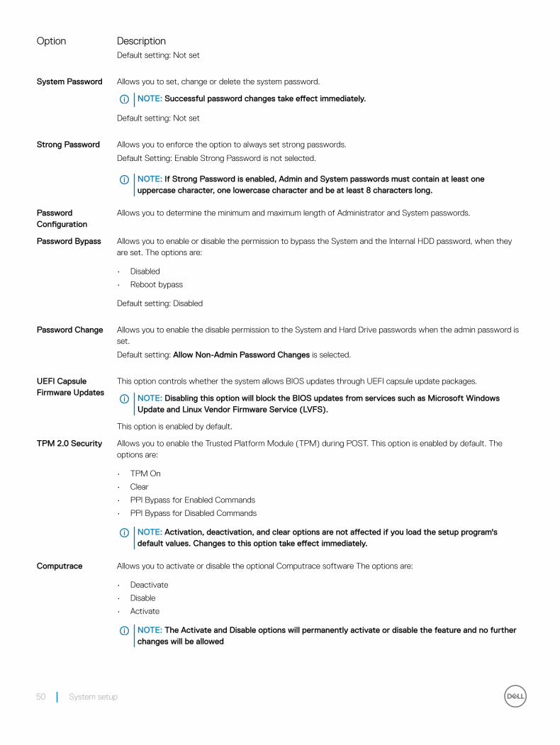
Option DescriptionDefault setting: Not set
System Password Allows you to set, change or delete the system password.
NOTE: Successful password changes take effect immediately.
Default setting: Not set
Strong Password Allows you to enforce the option to always set strong passwords.
Default Setting: Enable Strong Password is not selected.
NOTE: If Strong Password is enabled, Admin and System passwords must contain at least one uppercase character, one lowercase character and be at least 8 characters long.
Password Configuration
Allows you to determine the minimum and maximum length of Administrator and System passwords.
Password Bypass Allows you to enable or disable the permission to bypass the System and the Internal HDD password, when they are set. The options are:
• Disabled
• Reboot bypass
Default setting: Disabled
Password Change Allows you to enable the disable permission to the System and Hard Drive passwords when the admin password is set.
Default setting: Allow Non-Admin Password Changes is selected.
UEFI Capsule Firmware Updates
This option controls whether the system allows BIOS updates through UEFI capsule update packages.
NOTE: Disabling this option will block the BIOS updates from services such as Microsoft Windows Update and Linux Vendor Firmware Service (LVFS).
This option is enabled by default.
TPM 2.0 Security Allows you to enable the Trusted Platform Module (TPM) during POST. This option is enabled by default. The options are:
• TPM On
• Clear
• PPI Bypass for Enabled Commands
• PPI Bypass for Disabled Commands
NOTE: Activation, deactivation, and clear options are not affected if you load the setup program's default values. Changes to this option take effect immediately.
Computrace Allows you to activate or disable the optional Computrace software The options are:
• Deactivate
• Disable
• Activate
NOTE: The Activate and Disable options will permanently activate or disable the feature and no further changes will be allowed
50 System setup
Option DescriptionDefault setting: Deactivate
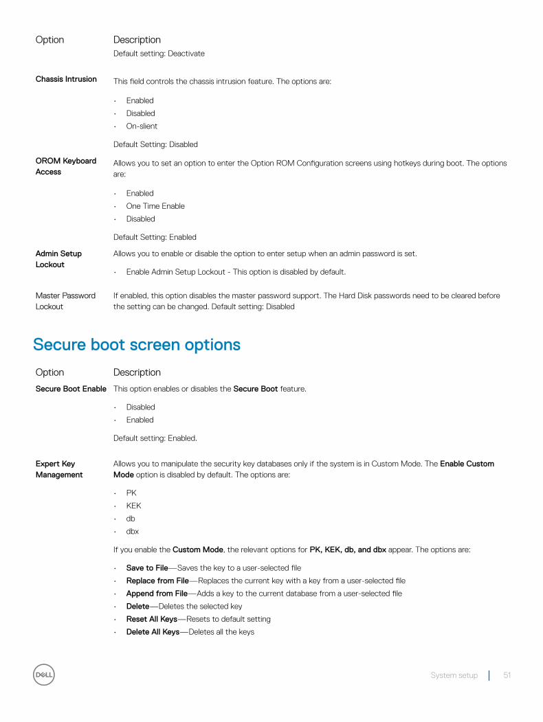
Chassis Intrusion This field controls the chassis intrusion feature. The options are:
• Enabled
• Disabled
• On-slient
Default Setting: Disabled
OROM Keyboard Access
Allows you to set an option to enter the Option ROM Configuration screens using hotkeys during boot. The options are:
• Enabled
• One Time Enable
• Disabled
Default Setting: Enabled
Admin Setup Lockout
Allows you to enable or disable the option to enter setup when an admin password is set.
• Enable Admin Setup Lockout - This option is disabled by default.
Master Password Lockout
If enabled, this option disables the master password support. The Hard Disk passwords need to be cleared before the setting can be changed. Default setting: Disabled
Secure boot screen options
Option Description
Secure Boot Enable This option enables or disables the Secure Boot feature.
• Disabled
• Enabled
Default setting: Enabled.
Expert Key Management
Allows you to manipulate the security key databases only if the system is in Custom Mode. The Enable Custom Mode option is disabled by default. The options are:
• PK
• KEK
• db
• dbx
If you enable the Custom Mode, the relevant options for PK, KEK, db, and dbx appear. The options are:
• Save to File—Saves the key to a user-selected file
• Replace from File—Replaces the current key with a key from a user-selected file
• Append from File—Adds a key to the current database from a user-selected file
• Delete—Deletes the selected key
• Reset All Keys—Resets to default setting
• Delete All Keys—Deletes all the keys
System setup 51
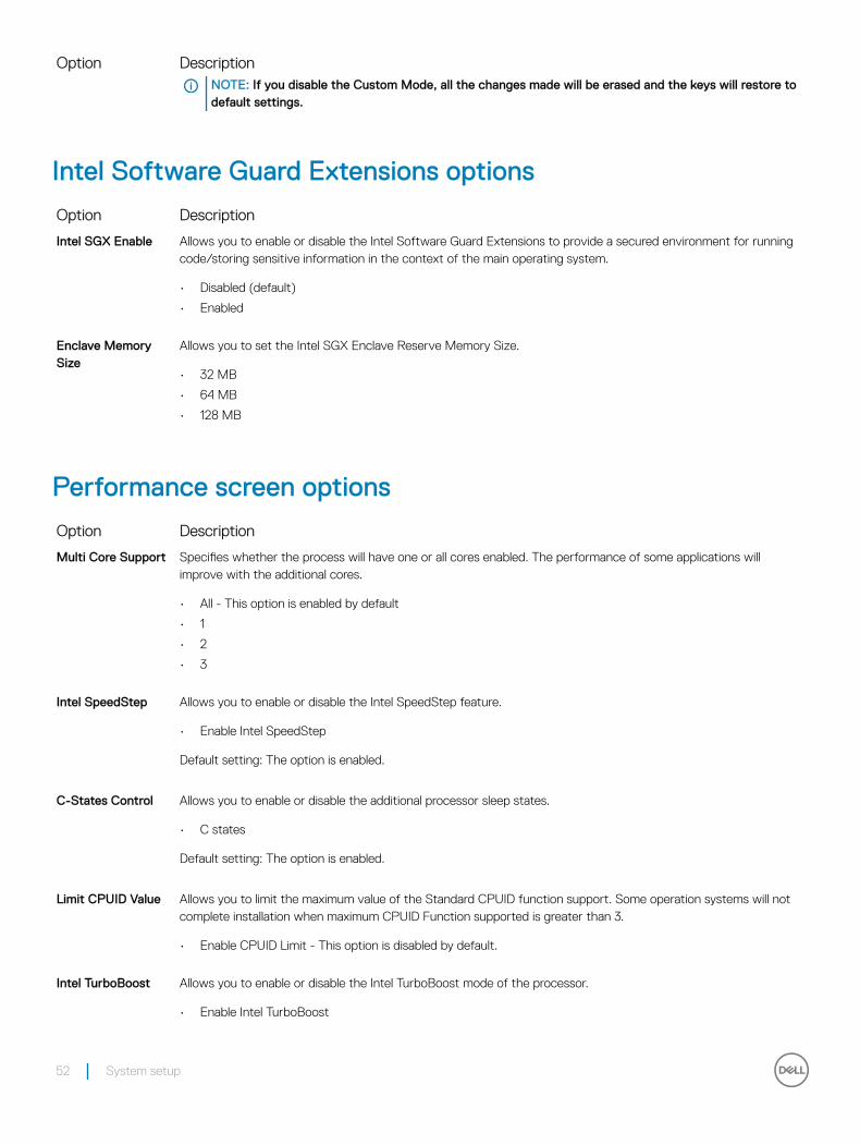
Option DescriptionNOTE: If you disable the Custom Mode, all the changes made will be erased and the keys will restore to default settings.
Intel Software Guard Extensions options
Option Description
Intel SGX Enable Allows you to enable or disable the Intel Software Guard Extensions to provide a secured environment for running code/storing sensitive information in the context of the main operating system.
• Disabled (default)
• Enabled
Enclave Memory Size
Allows you to set the Intel SGX Enclave Reserve Memory Size.
• 32 MB
• 64 MB
• 128 MB
Performance screen options
Option Description
Multi Core Support Specifies whether the process will have one or all cores enabled. The performance of some applications will improve with the additional cores.
• All - This option is enabled by default
• 1
• 2
• 3
Intel SpeedStep Allows you to enable or disable the Intel SpeedStep feature.
• Enable Intel SpeedStep
Default setting: The option is enabled.
C-States Control Allows you to enable or disable the additional processor sleep states.
• C states
Default setting: The option is enabled.
Limit CPUID Value Allows you to limit the maximum value of the Standard CPUID function support. Some operation systems will not complete installation when maximum CPUID Function supported is greater than 3.
• Enable CPUID Limit - This option is disabled by default.
Intel TurboBoost Allows you to enable or disable the Intel TurboBoost mode of the processor.
• Enable Intel TurboBoost
52 System setup
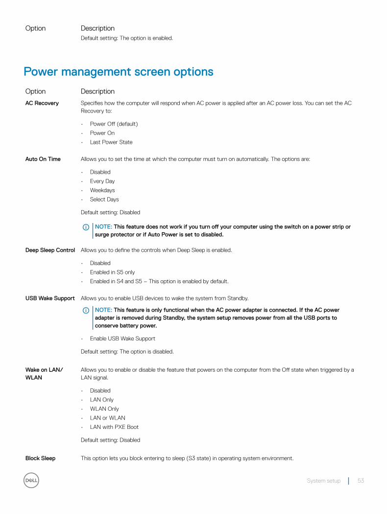
Option DescriptionDefault setting: The option is enabled.
Power management screen options
Option Description
AC Recovery Specifies how the computer will respond when AC power is applied after an AC power loss. You can set the AC Recovery to:
• Power Off (default)
• Power On
• Last Power State
Auto On Time Allows you to set the time at which the computer must turn on automatically. The options are:
• Disabled
• Every Day
• Weekdays
• Select Days
Default setting: Disabled
NOTE: This feature does not work if you turn off your computer using the switch on a power strip or surge protector or if Auto Power is set to disabled.
Deep Sleep Control Allows you to define the controls when Deep Sleep is enabled.
• Disabled
• Enabled in S5 only
• Enabled in S4 and S5 – This option is enabled by default.
USB Wake Support Allows you to enable USB devices to wake the system from Standby.
NOTE: This feature is only functional when the AC power adapter is connected. If the AC power adapter is removed during Standby, the system setup removes power from all the USB ports to conserve battery power.
• Enable USB Wake Support
Default setting: The option is disabled.
Wake on LAN/WLAN
Allows you to enable or disable the feature that powers on the computer from the Off state when triggered by a LAN signal.
• Disabled
• LAN Only
• WLAN Only
• LAN or WLAN
• LAN with PXE Boot
Default setting: Disabled
Block Sleep This option lets you block entering to sleep (S3 state) in operating system environment.
System setup 53
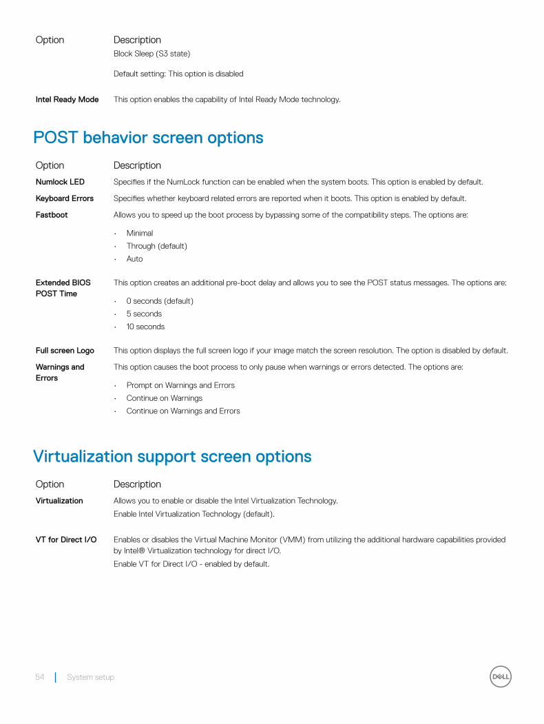
Option DescriptionBlock Sleep (S3 state)
Default setting: This option is disabled
Intel Ready Mode This option enables the capability of Intel Ready Mode technology.
POST behavior screen options
Option Description
Numlock LED Specifies if the NumLock function can be enabled when the system boots. This option is enabled by default.
Keyboard Errors Specifies whether keyboard related errors are reported when it boots. This option is enabled by default.
Fastboot Allows you to speed up the boot process by bypassing some of the compatibility steps. The options are:
• Minimal
• Through (default)
• Auto
Extended BIOS POST Time
This option creates an additional pre-boot delay and allows you to see the POST status messages. The options are:
• 0 seconds (default)
• 5 seconds
• 10 seconds
Full screen Logo This option displays the full screen logo if your image match the screen resolution. The option is disabled by default.
Warnings and Errors
This option causes the boot process to only pause when warnings or errors detected. The options are:
• Prompt on Warnings and Errors
• Continue on Warnings
• Continue on Warnings and Errors
Virtualization support screen options
Option Description
Virtualization Allows you to enable or disable the Intel Virtualization Technology.
Enable Intel Virtualization Technology (default).
VT for Direct I/O Enables or disables the Virtual Machine Monitor (VMM) from utilizing the additional hardware capabilities provided by Intel® Virtualization technology for direct I/O.
Enable VT for Direct I/O - enabled by default.
54 System setup
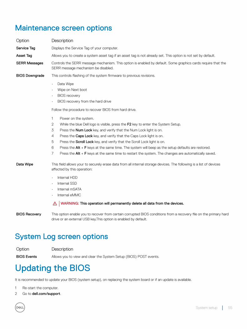
Maintenance screen options
Option Description
Service Tag Displays the Service Tag of your computer.
Asset Tag Allows you to create a system asset tag if an asset tag is not already set. This option is not set by default.
SERR Messages Controls the SERR message mechanism. This option is enabled by default. Some graphics cards require that the SERR message mechanism be disabled.
BIOS Downgrade This controls flashing of the system firmware to previous revisions.
• Data Wipe
• Wipe on Next boot
• BIOS recovery
• BIOS recovery from the hard drive
Follow the procedure to recover BIOS from hard drive.
1 Power on the system.
2 While the blue Dell logo is visible, press the F2 key to enter the System Setup.
3 Press the Num Lock key, and verify that the Num Lock light is on.
4 Press the Caps Lock key, and verify that the Caps Lock light is on.
5 Press the Scroll Lock key, and verify that the Scroll Lock light is on.
6 Press the Alt + F keys at the same time. The system will beep as the setup defaults are restored.
7 Press the Alt + F keys at the same time to restart the system. The changes are automatically saved.
Data Wipe This field allows your to securely erase data from all internal storage devices. The following is a list of devices affected by this operation:
• Internal HDD
• Internal SSD
• Internal mSATA
• Internal eMMC
WARNING: This operation will permanently delete all data from the devices.
BIOS Recovery This option enable you to recover from certain corrupted BIOS conditions from a recovery file on the primary hard drive or an external USB key.This option is enabled by default.
System Log screen options
Option Description
BIOS Events Allows you to view and clear the System Setup (BIOS) POST events.
Updating the BIOS It is recommended to update your BIOS (system setup), on replacing the system board or if an update is available.
1 Re-start the computer.
2 Go to dell.com/support.
System setup 55
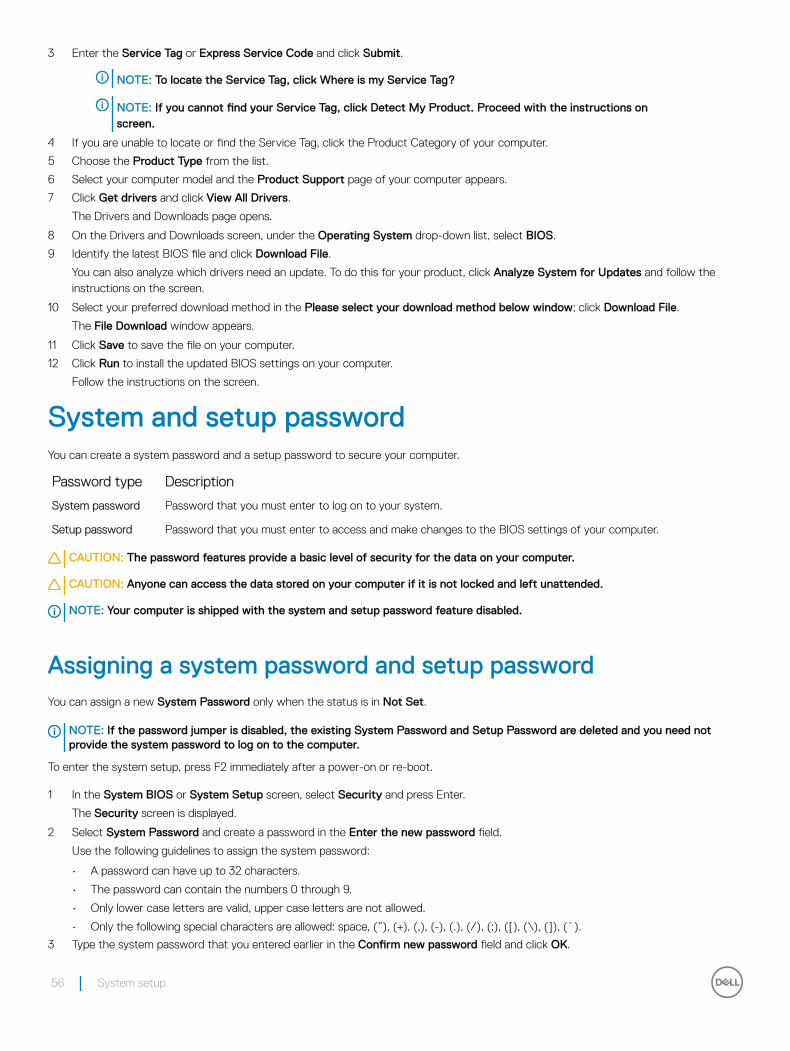
3 Enter the Service Tag or Express Service Code and click Submit.
NOTE: To locate the Service Tag, click Where is my Service Tag?
NOTE: If you cannot find your Service Tag, click Detect My Product. Proceed with the instructions on screen.
4 If you are unable to locate or find the Service Tag, click the Product Category of your computer.
5 Choose the Product Type from the list.
6 Select your computer model and the Product Support page of your computer appears.
7 Click Get drivers and click View All Drivers.
The Drivers and Downloads page opens.
8 On the Drivers and Downloads screen, under the Operating System drop-down list, select BIOS.
9 Identify the latest BIOS file and click Download File.
You can also analyze which drivers need an update. To do this for your product, click Analyze System for Updates and follow the instructions on the screen.
10 Select your preferred download method in the Please select your download method below window; click Download File.
The File Download window appears.
11 Click Save to save the file on your computer.
12 Click Run to install the updated BIOS settings on your computer.
Follow the instructions on the screen.
System and setup passwordYou can create a system password and a setup password to secure your computer.
Password type Description
System password Password that you must enter to log on to your system.
Setup password Password that you must enter to access and make changes to the BIOS settings of your computer.
CAUTION: The password features provide a basic level of security for the data on your computer.
CAUTION: Anyone can access the data stored on your computer if it is not locked and left unattended.
NOTE: Your computer is shipped with the system and setup password feature disabled.
Assigning a system password and setup passwordYou can assign a new System Password only when the status is in Not Set.
NOTE: If the password jumper is disabled, the existing System Password and Setup Password are deleted and you need not provide the system password to log on to the computer.
To enter the system setup, press F2 immediately after a power-on or re-boot.
1 In the System BIOS or System Setup screen, select Security and press Enter.
The Security screen is displayed.
2 Select System Password and create a password in the Enter the new password field.
Use the following guidelines to assign the system password:
• A password can have up to 32 characters.
• The password can contain the numbers 0 through 9.
• Only lower case letters are valid, upper case letters are not allowed.
• Only the following special characters are allowed: space, (”), (+), (,), (-), (.), (/), (;), ([), (\), (]), (`).
3 Type the system password that you entered earlier in the Confirm new password field and click OK.
56 System setup
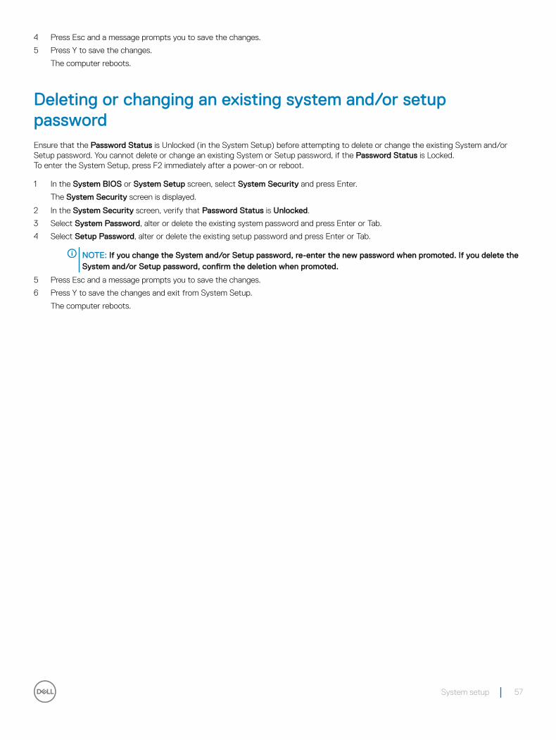
4 Press Esc and a message prompts you to save the changes.
5 Press Y to save the changes.
The computer reboots.
Deleting or changing an existing system and/or setup passwordEnsure that the Password Status is Unlocked (in the System Setup) before attempting to delete or change the existing System and/or Setup password. You cannot delete or change an existing System or Setup password, if the Password Status is Locked.To enter the System Setup, press F2 immediately after a power-on or reboot.
1 In the System BIOS or System Setup screen, select System Security and press Enter.
The System Security screen is displayed.
2 In the System Security screen, verify that Password Status is Unlocked.
3 Select System Password, alter or delete the existing system password and press Enter or Tab.
4 Select Setup Password, alter or delete the existing setup password and press Enter or Tab.
NOTE: If you change the System and/or Setup password, re-enter the new password when promoted. If you delete the System and/or Setup password, confirm the deletion when promoted.
5 Press Esc and a message prompts you to save the changes.
6 Press Y to save the changes and exit from System Setup.
The computer reboots.
System setup 57
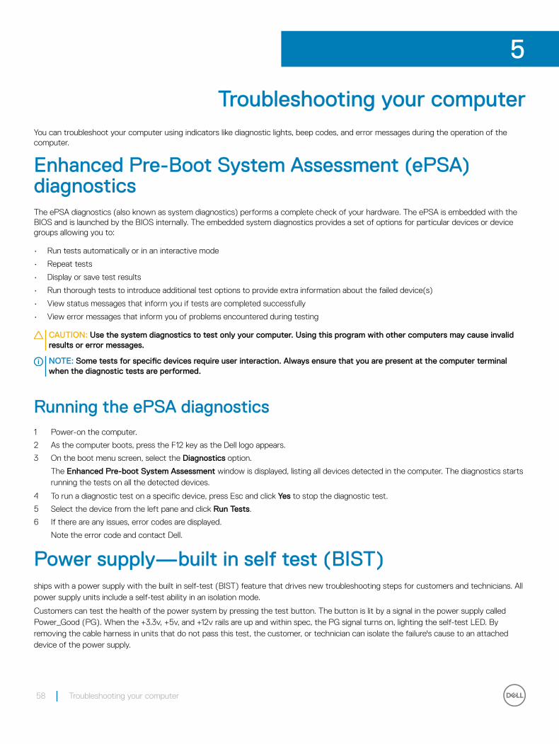
Troubleshooting your computerYou can troubleshoot your computer using indicators like diagnostic lights, beep codes, and error messages during the operation of the computer.
Enhanced Pre-Boot System Assessment (ePSA) diagnosticsThe ePSA diagnostics (also known as system diagnostics) performs a complete check of your hardware. The ePSA is embedded with the BIOS and is launched by the BIOS internally. The embedded system diagnostics provides a set of options for particular devices or device groups allowing you to:
• Run tests automatically or in an interactive mode
• Repeat tests
• Display or save test results
• Run thorough tests to introduce additional test options to provide extra information about the failed device(s)
• View status messages that inform you if tests are completed successfully
• View error messages that inform you of problems encountered during testing
CAUTION: Use the system diagnostics to test only your computer. Using this program with other computers may cause invalid results or error messages.
NOTE: Some tests for specific devices require user interaction. Always ensure that you are present at the computer terminal when the diagnostic tests are performed.
Running the ePSA diagnostics1 Power-on the computer.
2 As the computer boots, press the F12 key as the Dell logo appears.
3 On the boot menu screen, select the Diagnostics option.
The Enhanced Pre-boot System Assessment window is displayed, listing all devices detected in the computer. The diagnostics starts running the tests on all the detected devices.
4 To run a diagnostic test on a specific device, press Esc and click Yes to stop the diagnostic test.
5 Select the device from the left pane and click Run Tests.
6 If there are any issues, error codes are displayed.
Note the error code and contact Dell.
Power supply—built in self test (BIST)ships with a power supply with the built in self-test (BIST) feature that drives new troubleshooting steps for customers and technicians. All power supply units include a self-test ability in an isolation mode.
Customers can test the health of the power system by pressing the test button. The button is lit by a signal in the power supply called Power_Good (PG). When the +3.3v, +5v, and +12v rails are up and within spec, the PG signal turns on, lighting the self-test LED. By removing the cable harness in units that do not pass this test, the customer, or technician can isolate the failure's cause to an attached device of the power supply.
5
58 Troubleshooting your computer
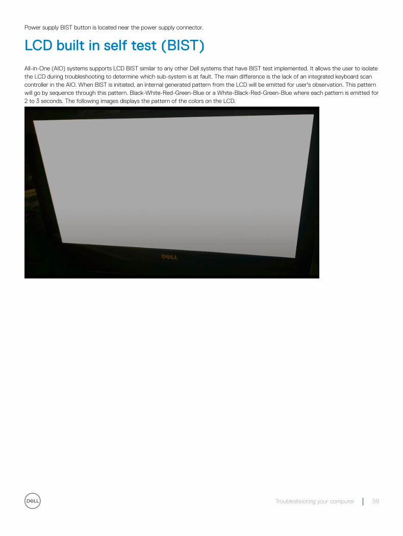
Power supply BIST button is located near the power supply connector.
LCD built in self test (BIST)All-in-One (AIO) systems supports LCD BIST similar to any other Dell systems that have BIST test implemented. It allows the user to isolate the LCD during troubleshooting to determine which sub-system is at fault. The main difference is the lack of an integrated keyboard scan controller in the AIO. When BIST is initiated, an internal generated pattern from the LCD will be emitted for user's observation. This pattern will go by sequence through this pattern. Black-White-Red-Green-Blue or a White-Black-Red-Green-Blue where each pattern is emitted for 2 to 3 seconds. The following images displays the pattern of the colors on the LCD.
Troubleshooting your computer 59

60 Troubleshooting your computer
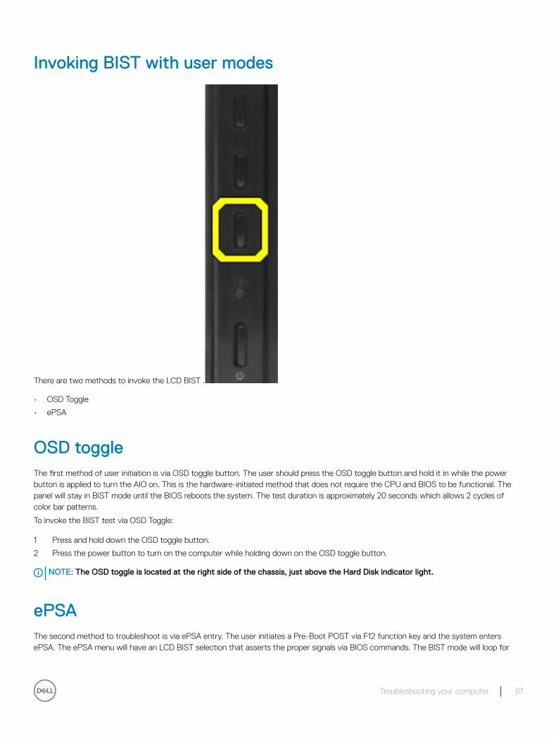
Invoking BIST with user modes
There are two methods to invoke the LCD BIST .
• OSD Toggle
• ePSA
OSD toggleThe first method of user initiation is via OSD toggle button. The user should press the OSD toggle button and hold it in while the power button is applied to turn the AIO on. This is the hardware-initiated method that does not require the CPU and BIOS to be functional. The panel will stay in BIST mode until the BIOS reboots the system. The test duration is approximately 20 seconds which allows 2 cycles of color bar patterns.
To invoke the BIST test via OSD Toggle:
1 Press and hold down the OSD toggle button.
2 Press the power button to turn on the computer while holding down on the OSD toggle button.
NOTE: The OSD toggle is located at the right side of the chassis, just above the Hard Disk indicator light.
ePSAThe second method to troubleshoot is via ePSA entry. The user initiates a Pre-Boot POST via F12 function key and the system enters ePSA. The ePSA menu will have an LCD BIST selection that asserts the proper signals via BIOS commands. The BIST mode will loop for
Troubleshooting your computer 61

approximately 20 seconds giving 2 cycles of color bar patterns that the user can observe. The time period is controlled by BIOS. After the time period, the BIOS will return the system to the ePSA menu.
62 Troubleshooting your computer
Technical specificationsNOTE: Offerings may vary by region. For more information regarding the configuration of your computer in:
• Windows 10, click or tap Start > Settings > System > About.
• Windows 8.1 and Windows 8, from the charms sidebar, click or tap Settings > Change PC settings. In the PC Settings window, select PC and devices > PC Info.
• Windows 7, click Start , right-click My Computer, and then select Properties.
Topics:
• System specifications
• Memory specifications
• Video specifications
• Audio specifications
• Communication specifications
• Cards specifications
• Display specifications
• Drives specifications
• Port and connector specifications
• Power specifications
• Camera (optional) specifications
• Stand specifications
• Physical specifications
• Environmental specifications
System specificationsFeature Specification
Processor cache Intel Core i3/ i5 / i7 series
Total cache Up to 8 MB cache depending on processor type
Chipset Intel Q170 chipset
Memory specificationsFeature Specification
Memory type up to 1600 MHz, unbuffered non-ECC, dual‐channel DDR4 2133 configuration
Memory capacity 4 GB and 8 GB
6
Technical specifications 63
Feature Specification
Memory connectors two internally-accessible DDR4 SODIMM sockets
Minimum memory 4 GB
Maximum memory 16 GB
Video specificationsFeature Specification
Video Controller (Integrated)
Integrated Intel HD Graphics (Gen 9 iGfx), 2GB GDDR5 for dGPU
Video Memory shared memory
External display support
Display port, HDMI in and HDMI out
Audio specificationsFeature Specification
Controller Intel High Definition Audio with Waves MaxxVoice Pro
Speaker single 4-ohms speakers in both the left and right speaker assembly (4 W average per channel)
Internal speaker amplifier
up to 7.6 W at 4-ohm per channel
Internal microphone support
dual digital microphone
Volume controls Volume up/down buttons, program menus, and keyboard media-control keys
WARNING: Excessive sound pressure from earphones or headphones can cause hearing damage or loss. Adjustment of the volume control as well as the equalizer to settings other than the center position may increase the earphones or headphones output voltage, and therefore the sound pressure level. The use of factors influencing the earphones or headphones output other than those specified by the manufacturer(e.g. operating system, equalizer software, firmware, driver, etc.) may increase the earphones or headphones output voltage and therefore the sound pressure level. The use of earphones or headphones other than those specified by the manufacturer may lead to heightened sound pressure level.
Communication specificationsFeatures Specification
Network adapter Intel 10/100/1000 Mbps RJ-45 Ethernet
Wireless• M.2 2230 card
• combo M.2 card (Intel Wireless 8260 M.2 PCIe WLAN card (802.11n/ac) with Bluetooth)
64 Technical specifications
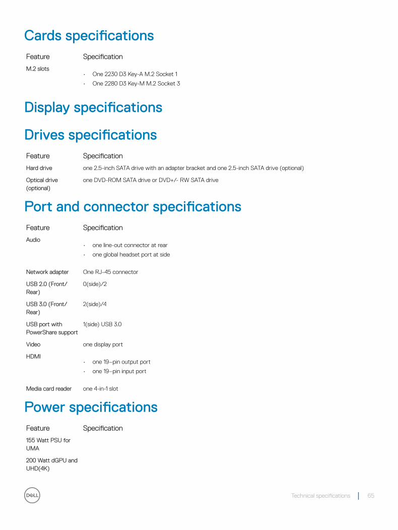
Cards specificationsFeature Specification
M.2 slots• One 2230 D3 Key-A M.2 Socket 1
• One 2280 D3 Key-M M.2 Socket 3
Display specifications
Drives specificationsFeature Specification
Hard drive one 2.5-inch SATA drive with an adapter bracket and one 2.5-inch SATA drive (optional)
Optical drive (optional)
one DVD-ROM SATA drive or DVD+/- RW SATA drive
Port and connector specificationsFeature Specification
Audio• one line-out connector at rear
• one global headset port at side
Network adapter One RJ-45 connector
USB 2.0 (Front/Rear)
0(side)/2
USB 3.0 (Front/Rear)
2(side)/4
USB port with PowerShare support
1(side) USB 3.0
Video one display port
HDMI• one 19–pin output port
• one 19–pin input port
Media card reader one 4-in-1 slot
Power specificationsFeature Specification
155 Watt PSU for UMA
200 Watt dGPU and UHD(4K)
Technical specifications 65
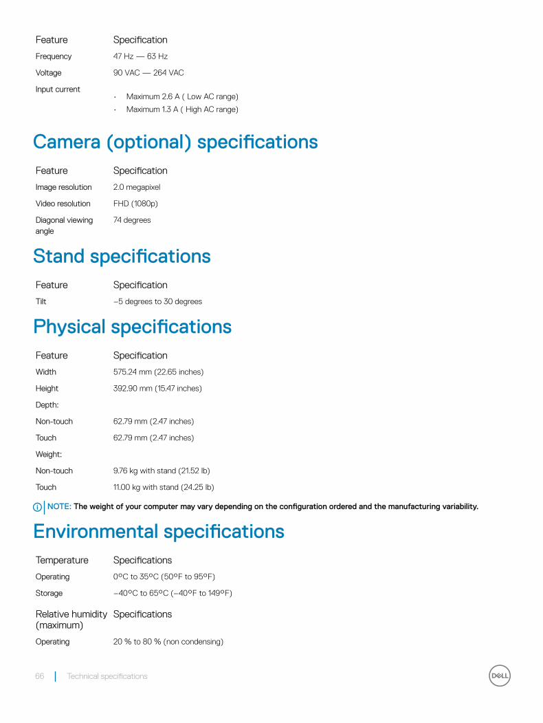
Feature Specification
Frequency 47 Hz — 63 Hz
Voltage 90 VAC — 264 VAC
Input current• Maximum 2.6 A ( Low AC range)
• Maximum 1.3 A ( High AC range)
Camera (optional) specificationsFeature Specification
Image resolution 2.0 megapixel
Video resolution FHD (1080p)
Diagonal viewing angle
74 degrees
Stand specificationsFeature Specification
Tilt –5 degrees to 30 degrees
Physical specificationsFeature Specification
Width 575.24 mm (22.65 inches)
Height 392.90 mm (15.47 inches)
Depth:
Non-touch 62.79 mm (2.47 inches)
Touch 62.79 mm (2.47 inches)
Weight:
Non-touch 9.76 kg with stand (21.52 lb)
Touch 11.00 kg with stand (24.25 lb)
NOTE: The weight of your computer may vary depending on the configuration ordered and the manufacturing variability.
Environmental specificationsTemperature Specifications
Operating 0°C to 35°C (50°F to 95°F)
Storage –40°C to 65°C (–40°F to 149°F)
Relative humidity (maximum)
Specifications
Operating 20 % to 80 % (non condensing)
66 Technical specifications
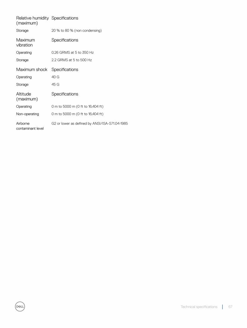
Relative humidity (maximum)
Specifications
Storage 20 % to 80 % (non condensing)
Maximum vibration
Specifications
Operating 0.26 GRMS at 5 to 350 Hz
Storage 2.2 GRMS at 5 to 500 Hz
Maximum shock Specifications
Operating 40 G
Storage 45 G
Altitude (maximum)
Specifications
Operating 0 m to 5000 m (0 ft to 16,404 ft)
Non-operating 0 m to 5000 m (0 ft to 16,404 ft)
Airborne contaminant level
G2 or lower as defined by ANSI/ISA-S71.04-1985
Technical specifications 67
Contacting DellNOTE: If you do not have an active Internet connection, you can find contact information on your purchase invoice, packing slip, bill, or Dell product catalog.
Dell provides several online and telephone-based support and service options. Availability varies by country and product, and some services may not be available in your area. To contact Dell for sales, technical support, or customer service issues:
1 Go to Dell.com/support.
2 Select your support category.
3 Verify your country or region in the Choose a Country/Region drop-down list at the bottom of the page.
4 Select the appropriate service or support link based on your need.
7
68 Contacting Dell