Embed Size (px)
Citation preview
Dell EMC Configuration and Troubleshooting Guide
Dell EMC PowerEdge MX SmartFabric Configuration and Troubleshooting Guide
Abstract This document provides the steps for configuring and troubleshooting the Dell EMC PowerEdge MX networking switches in SmartFabric mode. Configuration examples include Dell EMC Networking, Cisco Nexus, and Cisco ACI environments. This document replaces the Dell EMC PowerEdge MX SmartFabric Mode Deployment Guide, which is now deprecated. May 2019

2 Dell EMC PowerEdge MX SmartFabric Configuration and Troubleshooting Guide
Revisions Date Description
May 2019 Initial Release
The information in this publication is provided “as is.” Dell Inc. makes no representations or warranties of any kind with respect to the information in this publication, and specifically disclaims implied warranties of merchantability or fitness for a particular purpose. Use, copying, and distribution of any software described in this publication requires an applicable software license. © 2019 Dell Inc. or its subsidiaries. All Rights Reserved. Dell, EMC, Dell EMC and other trademarks are trademarks of Dell Inc. or its subsidiaries. Other trademarks may be trademarks of their respective owners. Dell believes the information in this document is accurate as of its publication date. The information is subject to change without notice.

3 Dell EMC PowerEdge MX SmartFabric Configuration and Troubleshooting Guide
Table of contents Revisions............................................................................................................................................................................. 2
1 Introduction ................................................................................................................................................................... 8
1.1 Typographical conventions ............................................................................................................................... 10
1.2 Attachments ...................................................................................................................................................... 10
2 SmartFabric Services for PowerEdge MX overview .................................................................................................. 11
2.1 Dell EMC OS10 Enterprise Edition ................................................................................................................... 11
2.2 Operating modes .............................................................................................................................................. 11
2.2.1 Full Switch mode .............................................................................................................................................. 12
2.2.2 SmartFabric mode ............................................................................................................................................ 12
2.3 Changing operating modes .............................................................................................................................. 14
2.4 MX9116n Fabric Switching Engine (FSE): virtual ports ................................................................................... 14
2.5 Virtual Link Trunking (VLT) ............................................................................................................................... 16
2.6 Server templates, identities, networks, and deployment .................................................................................. 16
2.6.1 Templates ......................................................................................................................................................... 16
2.6.2 Identities ........................................................................................................................................................... 17
2.6.3 Networks and automated QoS ......................................................................................................................... 17
2.6.4 Deployment ....................................................................................................................................................... 18
3 SmartFabric mode requirements, guidelines, and restrictions ................................................................................... 19
3.1 Create multi-chassis management group ......................................................................................................... 19
3.2 Upstream network requirements ...................................................................................................................... 19
3.3 Spanning Tree Protocol .................................................................................................................................... 20
3.4 VLAN scaling guidelines ................................................................................................................................... 20
3.5 Configuring port speed and breakout ............................................................................................................... 21
3.6 Storage Uplinks ................................................................................................................................................ 21
3.7 Switch slot placement for SmartFabric mode ................................................................................................... 22
3.7.1 Two MX9116n Fabric Switching Engines in different chassis .......................................................................... 22
3.7.2 Two MX5108n Ethernet switches in the same chassis .................................................................................... 22
3.7.3 Two MX9116n Fabric Switching Engines in the same chassis ........................................................................ 23
3.8 Switch-to-Switch cabling ................................................................................................................................... 23
3.9 NIC teaming guidelines .................................................................................................................................... 24
3.10 Identity pools ..................................................................................................................................................... 24
3.11 Other restrictions and guidelines ...................................................................................................................... 25
4 Creating a SmartFabric .............................................................................................................................................. 26
4.1 Physically cable MX chassis and upstream switches ....................................................................................... 26
4.2 Define VLANs ................................................................................................................................................... 26

4 Dell EMC PowerEdge MX SmartFabric Configuration and Troubleshooting Guide
4.3 Create the SmartFabric .................................................................................................................................... 27
4.4 Configure uplink port speed or breakout, if needed ......................................................................................... 28
4.5 Create the Ethernet uplinks .............................................................................................................................. 29
4.6 Configure the upstream switch and connect uplink cables .............................................................................. 31
5 Deploying a server ..................................................................................................................................................... 32
5.1 Server preparation ............................................................................................................................................ 32
5.1.1 Reset server CNAs to factory defaults ............................................................................................................. 32
5.1.2 Configure NIC partitioning on CNAs ................................................................................................................. 32
5.2 Create a server template .................................................................................................................................. 33
5.3 Create identity pools ......................................................................................................................................... 35
5.4 Associate server template with networks ......................................................................................................... 36
5.5 Deploy a server template .................................................................................................................................. 36
6 SmartFabric operations .............................................................................................................................................. 37
6.1 Viewing the fabric ............................................................................................................................................. 37
6.2 Editing the fabric ............................................................................................................................................... 39
6.3 Editing uplinks ................................................................................................................................................... 40
6.4 Editing VLANs on a deployed server ................................................................................................................ 42
7 Switch operations ....................................................................................................................................................... 44
7.1 Switch management page overview ................................................................................................................. 44
7.1.1 Switch overview ................................................................................................................................................ 44
7.1.2 Hardware tab .................................................................................................................................................... 46
7.1.3 Firmware tab ..................................................................................................................................................... 47
7.1.4 Alerts tab ........................................................................................................................................................... 47
7.1.5 Settings tab ....................................................................................................................................................... 48
7.2 Configure Ethernet switch ports from OME-M .................................................................................................. 50
7.3 Upgrading OS10EE .......................................................................................................................................... 52
8 Validating the SmartFabric deployment ..................................................................................................................... 55
8.1 View the MCM group topology ......................................................................................................................... 55
8.2 View the SmartFabric status ............................................................................................................................. 56
8.3 View port status ................................................................................................................................................ 58
8.4 CLI commands .................................................................................................................................................. 59
8.4.1 show switch-operating-mode ............................................................................................................................ 59
8.4.2 show discovered-expanders ............................................................................................................................. 59
8.4.3 show unit-provision ........................................................................................................................................... 59
8.4.4 show lldp neighbors .......................................................................................................................................... 59
8.4.5 show qos system .............................................................................................................................................. 61

5 Dell EMC PowerEdge MX SmartFabric Configuration and Troubleshooting Guide
8.4.6 show policy-map ............................................................................................................................................... 61
8.4.7 show class-map ................................................................................................................................................ 61
8.4.8 show vlt domain-id ............................................................................................................................................ 61
8.4.9 show vlt domain-id vlt-port-detail ...................................................................................................................... 62
8.4.10 show interface port channel summary ......................................................................................................... 62
9 Scenario 1 - SmartFabric deployment with Dell EMC PowerSwitch Z9100-ON upstream switches ......................... 63
9.1 Dell EMC PowerSwitch Z9100-ON switch configuration .................................................................................. 64
9.2 Dell EMC PowerSwitch Z9100-ON validation .................................................................................................. 66
9.2.1 show vlt ............................................................................................................................................................. 66
9.2.2 show lldp neighbors .......................................................................................................................................... 66
9.2.3 show spanning-tree brief .................................................................................................................................. 66
10 Scenario 2 - SmartFabric connected to Cisco Nexus 3232C switches ...................................................................... 68
10.1 Cisco Nexus 3232C switch configuration ......................................................................................................... 69
10.2 Configuration validation .................................................................................................................................... 71
10.2.1 show vpc ...................................................................................................................................................... 71
10.2.2 show vpc consistency-parameters ............................................................................................................... 72
10.2.3 show lldp neighbors...................................................................................................................................... 73
10.2.4 show spanning-tree summary ...................................................................................................................... 73
11 Scenario 3 - SmartFabric connected to Cisco ACI leaf switches ............................................................................... 74
11.1 Validated environment ...................................................................................................................................... 75
11.2 Cisco APIC configuration .................................................................................................................................. 77
11.3 Deploy a SmartFabric ....................................................................................................................................... 78
11.3.1 Define VLANs ............................................................................................................................................... 78
11.3.2 Create the SmartFabric ................................................................................................................................ 79
11.3.3 Define uplinks ............................................................................................................................................... 81
11.4 Deploy servers .................................................................................................................................................. 83
11.4.1 Create server templates ............................................................................................................................... 83
11.4.2 Add VLANs to the server templates ............................................................................................................. 83
11.4.3 Deploy the server templates ........................................................................................................................ 84
11.5 vCenter configuration overview ........................................................................................................................ 85
11.6 Verify configuration ........................................................................................................................................... 87
11.6.1 Cisco ACI validation ..................................................................................................................................... 87
11.6.2 Verify connectivity between VMs ................................................................................................................. 92
12 SmartFabric troubleshooting ...................................................................................................................................... 93
12.1 Troubleshooting errors encountered for port group breakout .......................................................................... 93
12.2 Troubleshooting Spanning Tree Protocol (STP) .............................................................................................. 95

6 Dell EMC PowerEdge MX SmartFabric Configuration and Troubleshooting Guide
12.2.1 Verify if STP is enabled on upstream switches ............................................................................................ 95
12.2.2 Verify if type of STP is the same on MX and upstream switches ................................................................ 95
12.3 Verify VLT/vPC configuration on upstream switches ....................................................................................... 96
12.4 Discovery of FEM and compute sleds .............................................................................................................. 96
12.5 Troubleshooting uplink errors ........................................................................................................................... 97
12.5.1 Toggle auto negotiation ................................................................................................................................ 97
12.5.2 Set uplink ports to administratively up.......................................................................................................... 98
12.5.3 Verify MTU size ............................................................................................................................................ 98
12.5.4 Verify auto negotiation settings on upstream switches ................................................................................ 98
12.5.5 Verify LACP .................................................................................................................................................. 99
12.6 Troubleshooting FC/FCoE .............................................................................................................................. 101
A Hardware overview ................................................................................................................................................... 102
A.1 Dell EMC PowerEdge MX7000 chassis ......................................................................................................... 102
A.2 Dell EMC PowerEdge MX740c compute sled ................................................................................................ 104
A.3 Dell EMC PowerEdge MX840c compute sled ................................................................................................ 105
A.4 Dell EMC PowerEdge MX9002m module ...................................................................................................... 106
A.5 Dell EMC Networking MX9116n Fabric Switching Engine ............................................................................. 107
A.6 Dell EMC Networking MX7116n Fabric Expander Module............................................................................. 108
A.7 Dell EMC Networking MX5108n Ethernet switch ........................................................................................... 108
A.8 PowerEdge MX7000 Fabrics I/O slots............................................................................................................ 109
A.9 Scalable fabric architecture overview ............................................................................................................. 110
A.10 QSFP28 double density connectors ............................................................................................................... 113
A.11 OOB management network ............................................................................................................................ 113
B OpenManage Enterprise Modular console ............................................................................................................... 115
B.1 PowerEdge MX9002m module cabling .......................................................................................................... 115
B.2 PowerEdge MX7000 initial deployment .......................................................................................................... 115
B.3 PowerEdge MX Ethernet I/O Module initial deployment ................................................................................ 117
C Rack-mounted switches ........................................................................................................................................... 119
C.1 Dell EMC PowerSwitch S3048-ON................................................................................................................. 119
C.2 Dell EMC PowerSwitch Z9100-ON ................................................................................................................. 119
C.3 Cisco Nexus 3232C ........................................................................................................................................ 119
C.4 Cisco Nexus C93180YC-EX ........................................................................................................................... 119
C.5 Cisco Nexus C9336-PQ ................................................................................................................................. 119
D Additional information ............................................................................................................................................... 120
D.1 Delete a SmartFabric ...................................................................................................................................... 120
D.2 Delete an MCM group .................................................................................................................................... 120

7 Dell EMC PowerEdge MX SmartFabric Configuration and Troubleshooting Guide
D.3 Reset chassis using RACADM ....................................................................................................................... 120
D.4 Reset an OS10EE switch to factory defaults .................................................................................................. 121
D.5 Reset Cisco Nexus 3232C to factory defaults ................................................................................................ 121
E Validated components .............................................................................................................................................. 122
E.1 Scenarios 1 and 2 ........................................................................................................................................... 122
E.1.1 Dell EMC Networking switches ....................................................................................................................... 122
E.1.2 Dell EMC PowerEdge MX7000 chassis and components ............................................................................. 122
E.1.3 Cisco Nexus switches ..................................................................................................................................... 123
E.2 Scenario 3 ....................................................................................................................................................... 123
E.2.1 Dell EMC Networking switches ....................................................................................................................... 123
E.2.2 Dell EMC PowerEdge MX7000 chassis and components ............................................................................. 123
E.2.3 Cisco ACI components ................................................................................................................................... 124
F Technical resources ................................................................................................................................................. 125
G Support and feedback .............................................................................................................................................. 126

8 Dell EMC PowerEdge MX SmartFabric Configuration and Troubleshooting Guide
1 Introduction The Dell EMC PowerEdge MX is a unified, high-performance data center infrastructure. The PowerEdge MX provides the agility, resiliency, and efficiency to optimize a wide variety of traditional and new, emerging data center workloads and applications. With its kinetic architecture and agile management, PowerEdge MX dynamically configures compute, storage, and fabric, increases team effectiveness, and accelerates operations. The responsive design delivers the innovation and longevity that customers need for their IT and digital business transformations.
As part of the PowerEdge MX platform, Dell EMC Networking OS10 Enterprise Edition includes SmartFabric Services. SmartFabric Services is a network automation and orchestration solution that is fully integrated with the MX Platform.
Dell EMC PowerEdge MX7000 chassis
This document provides information about OS10 Enterprise Edition SmartFabric Services running on the PowerEdge MX platform. This document also provides examples for the deployment of two PowerEdge MX7000 chassis and the setup and configuration of the SmartFabric. In SmartFabric mode, switches operate as Layer 2 I/O aggregation fabric and are managed through the Open Manage Enterprise Modular (OME-M) console.
This guide also demonstrates connectivity with different upstream switch options, including:
• Dell EMC PowerSwitch Z9100-ON • Cisco Nexus 3232C • Cisco Nexus C93180YC-EX in Application Centric Infrastructure (ACI) mode

9 Dell EMC PowerEdge MX SmartFabric Configuration and Troubleshooting Guide
NOTE: For a detailed overview of the PowerEdge MX hardware, see Appendix A. For more information about the PowerEdge MX network architecture, see the Dell EMC PowerEdge MX Networking Architecture Guide.
NOTE: The examples in document assume that the MX7000 chassis are configured in a Multi-Chassis Management group and that no errors have been found. Additionally, this guide assumes the reader has a basic understanding of the PowerEdge MX platform.
Four important terminologies and their definitions are as follows:
Scalable Fabric – Exclusive to the MX7000 platform. This is an architecture comprised of the Dell EMC Networking MX9116n Fabric Switching Engine and Dell EMC Networking MX7116n Fabric Expander Module allowing a fabric to span up to ten MX7000 chassis. This creates a single network fabric enabling efficient east/west traffic flows between participating chassis. Supported in both SmartFabric and Full Switch modes.
SmartFabric Mode - SmartFabric Mode leverages Smart Fabric Services (see below) to create a Layer 2 network leveraging one to ten MX7000 chassis. Switches operating in SmartFabric Mode are administered through the OpenManage Enterprise - Modular (OME-M) GUI interfaces that provide complete lifecycle management of the network fabric.
Full Switch Mode – When operating in Full Switch Mode, the switch can perform any functionality supported by the version of OS10 running on the switch. Most of the configuration is performed using the CLI, not the OME-M GUI.
Smart Fabric Services (SFS) – In PowerEdge MX, SFS technology provides the underlying network automation and orchestration to support all automated network operations. SFS is the underlying technology for all Dell EMC Networking OS10 automation efforts including PowerEdge MX, Isilon back-end storage networking, VxRail network automation, and so on.
Table 1 outlines what this document is and is not. Also, this guide assumes a basic understanding of the PowerEdge MX platform.
Dell EMC PowerEdge MX SmartFabric Configuration and Troubleshooting Guide - is/is not
This guide is This guide is not/does not
A reference for the most used features of SmartFabric operating mode
A guide for all features of the MX7000 platform
A secondary reference to the Release Notes Take precedence over the Release Notes
NOTE: For a general overview of PowerEdge MX networking concepts, see the Dell EMC PowerEdge MX Network Architecture Guide.

10 Dell EMC PowerEdge MX SmartFabric Configuration and Troubleshooting Guide
1.1 Typographical conventions The CLI and GUI examples in this document use the following conventions:
Monospace Text CLI examples
Underlined Monospace Text CLI examples that wrap the page
Italic Monospace Text Variables in CLI examples
Bold Monospace Text Commands entered at the CLI prompt, or to highlight information in CLI output
Bold text UI elements and information entered in the GUI
1.2 Attachments This document in .pdf format includes one or more file attachments. To access attachments in Adobe Acrobat Reader, click the icon in the left pane halfway down the page, then click the icon.

11 Dell EMC PowerEdge MX SmartFabric Configuration and Troubleshooting Guide
2 SmartFabric Services for PowerEdge MX overview
2.1 Dell EMC OS10 Enterprise Edition The networking market is transitioning from a closed, proprietary stack to open hardware supporting a variety of operating systems. OS10 is designed to allow multi-layered disaggregation of the network functionality. While OS10 contributions to Open Source provide users freedom and flexibility to pick their own third party networking, monitoring, management and orchestration applications, OS10 Enterprise Edition (OS10EE) bundles industry hardened networking stack featuring standard L2 and L3 protocols over a standard and well accepted CLI interface.
OS10 High Level Architecture
2.2 Operating modes The Dell EMC Networking MX9116n FSE and MX5108n operate in one of two modes:
1. Full Switch mode (Default) – All switch-specific OS10EE capabilities are available 2. SmartFabric mode – Switches operate as layer 2 I/O aggregation fabric and are managed through
the Open Manage Enterprise Modular console
The following OS10EE CLI commands have been added specifically for the PowerEdge MX platform:
• show switch-operating-mode – displays the current operating mode (SmartFabric or Full Switch) of a supported switch

12 Dell EMC PowerEdge MX SmartFabric Configuration and Troubleshooting Guide
• show discovered-expanders – displays the MX7116n FEMs attached to the MX9116n FSEs
• show unit-provision – displays or configures the unit ID and service tag of a MX7116n FEM attached to a MX9116n FSE
NOTE: For more information, see the OS10 Enterprise Edition User Guide for PowerEdge MX I/O Modules on the Support for Dell EMC Networking MX9116n - Manuals and documents web page.
2.2.1 Full Switch mode In Full Switch mode, all OS10EE features and functions supported by the hardware are available to the user. In other words, the switch operates the same way as any other OS10EE switch. Configuration is primarily done using the CLI, however, the following items can be configured or managed using the OME-M graphical user interface:
1. Initial switch deployment: Configure Hostname, password, SNMP, NTP, etc. 2. Set port administratively up or down, configure MTU 3. Monitor Health, logs, alerts, and events 4. Update or manage the OS10EE version 5. View physical topology 6. Power Management
Full Switch Mode is typically used when a desired feature or function is not available when operating in SmartFabric Mode. For more information about OS10EE operations, see Dell EMC Networking OS Info Hub.
2.2.2 SmartFabric mode A SmartFabric is a logical entity that consists of a collection of physical resources, such as servers and switches, and logical resources such as networks, templates, and uplinks. The OpenManage Enterprise - Modular console provides a method to manage these resources as a single unit.
In the PowerEdge M1000e and FX2 platforms, I/O Aggregation (IOA) was implemented to simplify the process to connect blade servers to upstream networks, so server administrators and generalists could manage uplinks, downlinks, and VLAN assignments without needing to be fluent with the CLI.
SmartFabric Services mode builds on this IOA functionality providing:
1. Data center modernization • I/O Aggregation • Plug-and-play fabric deployment • Single interface to manage all switches in the fabric
2. Lifecycle management • Fabric-wide OS10EE updates • Automated or user enforced roll back to last well-known state
3. Fabric automation • Physical topology compliance • Server networking managed via templates • Automated QoS assignment per VLAN • Automated storage networking
4. Failure remediation • Dynamically adjusts bandwidth across all inter-switch links in the event of a link failure

13 Dell EMC PowerEdge MX SmartFabric Configuration and Troubleshooting Guide
• Automatically detects fabric misconfigurations or link level failure conditions • Automatically heals the fabric on failure condition removal
NOTE: In SmartFabric mode, MX series switches operate entirely as a Layer 2 network fabric. Layer 3 protocols are not supported.
When operating in SmartFabric mode, access to certain CLI commands is restricted to OS10EE show commands and the following subset of CLI configuration commands:
• clock – Configure clock parameters • end – Exit to the EXEC mode • exit – Exit from the current mode • help – Display available commands • hostname – Set the system hostname • interface – Configure or select an interface • ip nameserver – Configure nameserver • logging – Configure system logging • management route – Configure the IPV4/IPv6 management route • no – Delete or disable commands in configuration mode • ntp – Configure the network time protocol • snmp-server – Configure the SNMP server • username – Create or modify user credentials • spanning-tree commands:
- disable – Disable spanning tree globally - mac-flush-timer – Set the time used to flush MAC address entries - mode – Enable a spanning-tree mode, such as RSTP or MST - mst – Configure multiple spanning-tree (MST) mode - rstp – Configure rapid spanning-tree protocol (RSTP) mode - vlan – Configure spanning-tree on a VLAN range
Table 2 outlines the differences between the two operating modes and apply to both the MX9116n FSE and the MX5108n switches.
IOM operating mode differences
Full Switch mode SmartFabric mode
Configuration changes are persistent during power cycle events.
Only the configuration changes made using the OS10 commands below are persistent across power cycle events. All other CLI configuration commands are disabled.
clock hostname interface ip nameserver logging management route ntp snmp-server

14 Dell EMC PowerEdge MX SmartFabric Configuration and Troubleshooting Guide
Full Switch mode SmartFabric mode
username spanning-tree vlan
All switch interfaces are assigned to VLAN 1 by default and are in the same Layer 2 bridge domain.
Layer 2 bridging is disabled by default. Interfaces must join a bridge domain (VLAN) before being able to forward frames.
All configurations changes are saved in the running configuration by default. To display the current configuration, use the show running-configuration command.
Verify configuration changes using feature-specific show commands, such as show interface and show vlan, instead of show running-configuration.
2.3 Changing operating modes In both Full Switch and SmartFabric modes, all configuration changes you make using the OME-M GUI are retained when you switch modes. Dell EMC recommends using the graphical user interface for switch configuration in SmartFabric mode and the OS10EE CLI for switch configuration in Full Switch mode.
By default, a switch is in Full Switch mode. When that switch is added to a fabric, it automatically changes to SmartFabric mode. When you change from Full Switch to SmartFabric mode, all Full Switch CLI configurations are deleted except for the subset of CLI commands supported in SmartFabric mode.
To change a switch from SmartFabric to Full Switch mode, the fabric must be deleted. At that time, all SmartFabric GUI configuration changes are deleted except for the configurations supported by the subset of SmartFabric CLI commands (hostname, SNMP settings, etc.) and the changes you make to port interfaces, except for admin state (shutdown/no shutdown), MTU, speed, and auto-negotiation mode.
There is no CLI command to switch between operating modes. The CLI command show switch-operating-mode will display the currently configured operating mode of the switch. This information is also available on the switch landing page in the OME-Modular GUI.
2.4 MX9116n Fabric Switching Engine (FSE): virtual ports A virtual port is a logical switch port that connects to a downstream server and has no physical hardware location on the switch. Virtual ports are created when an MX9116n Fabric Switching Engine (FSE) on-boards an MX7116n Fabric Expander Module (FEM). The onboarding process consists of discovery and configuration.
NOTE: If the servers in the chassis have dual-port NICs, only QSFP28-DD port 1 on the FEM needs to be connected. Do not connect QSFP28-DD port 2.
To verify the auto-discovered Fabric Expanders, enter the show discovered-expanders command
OS10# show discovered-expanders Service-tag Model Type Chassis-service-tag Chassis-slot Port-group Virtual-Slot-Id -------------------------------------------------------------------------------- 403RPK2 MX7116n Fabric 1 SKY003Q A2 1/1/2 Expander Module

15 Dell EMC PowerEdge MX SmartFabric Configuration and Troubleshooting Guide
If the FSE is in SmartFabric mode, the attached FEM is automatically configured and virtual ports on the Fabric Expander and a virtual slot ID are created and mapped to 8x25GbE breakout interfaces in FEM mode on the Fabric Engine
A FSE in Full Switch mode automatically discovers the FEM when these conditions are met:
• The FEM is connected to the FSE by attaching a cable between the QSFP28-DD ports on both devices
• The interface for the QSFP28-DD port-group connected to on the FSE is in 8x25GbE FEM mode • At least one blade server is inserted into the MX7000 chassis containing the FEM
NOTE: If the FSE is in Full Switch mode, you must manually configure the unit ID of the FEM. See the OS10EE documentation for implementation.
Once the FSE discovers the FEM, it creates virtual ports by mapping each 8x25GbE FEM breakout interface in port groups 1 to 10 to a FEM virtual port. Table 3 shows an example of this mapping.
Virtual port mapping
FEM service tag FSE QSFP28-DD port group
FSE 25G interfaces
FEM unit ID (virtual slot ID) FEM virtual ports
12AB3456 portgroup1/1/1 1/1/17:1 71 1/71/1
1/1/17:2 1/71/2
1/1/17:3 1/71/3
1/1/17:4 1/71/4
1/1/18:1 1/71/5
1/1/18:2 1/71/6
1/1/18:3 1/71/7
1/1/18:4 1/71/8
When a QSFP28-DD port group is mapped to a FEM, in the show interface status output, the eight interfaces display dormant instead of up until a virtual port starts to transmit server traffic:
OS10# show interface status -------------------------------------------------------------------------------- Port Description Status Speed Duplex Mode Vlan Tagged-Vlans -------------------------------------------------------------------------------- ... Eth 1/1/17:1 dormant Eth 1/1/17:2 dormant Eth 1/1/17:3 dormant Eth 1/1/17:4 dormant Eth 1/1/18:1 dormant Eth 1/1/18:2 dormant Eth 1/1/18:3 dormant Eth 1/1/18:4 dormant ...

16 Dell EMC PowerEdge MX SmartFabric Configuration and Troubleshooting Guide
You can also use the show interface command to display the Fabric Engine physical port-to-Fabric Expander virtual port mapping, and the operational status of the line:
OS10# show interface ethernet 1/1/30:3 Ethernet 1/1/30:3 is up, line protocol is dormant Interface is mapped to ethernet1/77/7
NOTE: If you move a FEM by cabling it to a different QSFP28-DD port on the Fabric Engine, all software configurations on virtual ports are maintained. Only the QSFP28-DD breakout interfaces that map to the virtual ports change.
2.5 Virtual Link Trunking (VLT) Virtual Link Trunking (VLT) aggregates two identical physical switches to form a single logical extended switch. However, each of the VLT peers has its own control and data planes and can be configured individually for port, protocol, and management behaviors. Though the dual physical units act as a single logical unit, the control and data plane of both switches remain isolated, ensuring high availability and high resilience for all its connected devices. This differs from the legacy stacking concept, where there is a single control plane across all switches in the stack, creating a single point of failure.
With the critical need for high availability in modern data centers and enterprise networks, VLT plays a vital role connecting with rapid convergence, seamless traffic flow, efficient load balancing, and loop free capabilities.
With the instantaneous synchronization of MAC and ARP entries, both the nodes remain Active-Active and continue to forward the data traffic seamlessly.
VLT is required when operating in SmartFabric mode.
For more information on VLT, see the Virtual Link Trunking chapter in the OS10EE User Guide and Virtual Link Trunking (VLT) in Dell EMC OS10 Enterprise Edition Best Practices and Deployment Guide.
2.6 Server templates, identities, networks, and deployment For detailed information on templates, identities, and deployment, see the OpenManage Enterprise - Modular documentation and the technical paper PowerEdge MX7000: Templates and Profiles.
2.6.1 Templates A template is a set of system configuration settings referred to as attributes. A template may contain a small set of attributes for a specific purpose, or all the attributes for a full system configuration. Templates allow for multiple servers to be configured quickly and automatically without the risk of human error.
Networks (VLANs) are assigned to NICs as part of the server template. When the template is deployed, those networks are programmed on the fabric for the servers associated with the template.
NOTE: Network assignment through template only functions for servers connected to a SmartFabric. If a template with network assignments is deployed to a server connected to a switch in Full Switch mode, the network assignments are ignored.

17 Dell EMC PowerEdge MX SmartFabric Configuration and Troubleshooting Guide
OME-M provides options for creating templates:
• Most frequently, templates are created by getting the current system configuration from a server that has been configured to the exact specifications required (referred to as a “Reference Server”).
• Templates may be cloned (copied) and edited. • A template can be created by importing a Server Configuration Profile (SCP) file. The SCP file may
be from a server or exported by OpenManage Essentials, OpenManage Enterprise, or OME-M. • OME-M comes prepopulated with several templates for specific purposes.
2.6.2 Identities Some of the attributes included in a template are referred to as identity attributes. Identity attributes identify a device and distinguish it from all other devices on the network. Since identity attributes must uniquely identify a device, it is imperative that each device has a unique network identity. Otherwise, devices won’t be able to communicate with each other over the network.
Devices come with unique manufacturer-assigned identity values preinstalled, such as a factory-assigned MAC address. Those identities are fixed and never change. However, devices can assume a set of alternate identity values, called a “virtual identity”. A virtual identity functions on the network using that identity, as if the virtual identity were its factory-installed identity. The use of virtual identity is the basis for stateless operations.
OME-M provides virtual identities using Identity Pools. Just like factory-installed identities, virtual identities must also be unique on the network. Using virtual identities enables PowerEdge MX to support operations such as shifting, or migrating, a full device configuration that includes its virtual identity, from one server to another. In other words, a virtual identity can be removed from one device and assigned to a different device, for example, in case the original device stops working or needs maintenance.
2.6.3 Networks and automated QoS In addition to assigning VLANs to server profiles, SmartFabric automates QoS settings based on the Network Type specified. Figure 3 shows that when defining a VLAN, one of 11 options are pre-defined.
Network types available in SmartFabric mode

18 Dell EMC PowerEdge MX SmartFabric Configuration and Troubleshooting Guide
Table 4 lists the network types and related settings. The QoS group is the numerical value for the queues available in SmartFabric mode. Available queues include 2 through 5. Queues 1, 6, and 7 are reserved.
NOTE: In SmartFabric mode, an administrator cannot change the default weights for the queues.
Network types and default QoS settings
Network type Description QoS group
General Purpose (Bronze) Used for low priority data traffic 2
General Purpose (Silver) Used for standard/default priority data traffic 3
General Purpose (Gold) Used for high priority data traffic 4
General Purpose (Platinum) Used for extremely high priority data traffic 5
Cluster Interconnect Used for cluster heartbeat VLANs 5
Hypervisor Management Used for hypervisor management connections such as the ESXi management VLAN 5
Storage - iSCSI Used for iSCSI VLANs 5
Storage - FCoE Used for FCoE VLANs 5
Storage - Data Replication Used for VLANs supporting storage data replication such as for VMware VSAN
5
VM Migration Used for VLANs supporting vMotion and similar technologies
5
VMware FT Logging Used for VLANs supporting VMware Fault Tolerance 5
2.6.4 Deployment Deployment is the process of applying a full or partial system configuration on a specific target device. In OME-M, templates are the basis for all deployments. Templates contain the system configuration attributes that get sent to the target server, then the iDRAC on the target device applies the attributes contained in the template and reboots the server if necessary. Often, templates contain virtual identity attributes. As mentioned above, identity attributes must have unique values on the network. Identity Pools facilitate the assignment and management of unique virtual identities.

19 Dell EMC PowerEdge MX SmartFabric Configuration and Troubleshooting Guide
3 SmartFabric mode requirements, guidelines, and restrictions Before deploying a SmartFabric, ensure that the following requirements, guidelines, and restrictions are followed. Failure to do so may impact your network.
3.1 Create multi-chassis management group For a scalable fabric that uses more than one MX chassis, the chassis must be in a Multi-Chassis Management (MCM) Group. See Appendix B.1 for more details.
NOTE: SmartFabric mode can be enabled on a single chassis having two MX9116n FSEs or two MX5108n switches in each fabric. For a SmartFabric implemented using a single chassis, MCM group is not mandatory but recommended. The chassis must be in an MCM group for a SmartFabric containing more than one MX chassis.
3.2 Upstream network requirements All physical Ethernet connections within an Uplink from a SmartFabric are automatically grouped into a single LACP LAG. Because of this, all ports on the upstream switches must also be in a single LACP LAG. Failure to do so may create network loops.
A minimum of one physical uplink from each MX switch to each upstream switch is required and it is recommended that uplinks be connected in a mesh design.
NOTE: The upstream switch ports must be in a single LACP LAG as shown by VLT, vPC in the figure below. Creating multiple LAGs within a single uplink will result in a network loop.
Recommended upstream network connectivity

20 Dell EMC PowerEdge MX SmartFabric Configuration and Troubleshooting Guide
3.3 Spanning Tree Protocol By default, OS10EE uses Rapid per-VLAN Spanning Tree Plus (RPVST+) across all switching platforms including PowerEdge MX networking IOMs. OS10EE also supports RSTP. MST is not currently supported when using VLT, and therefore is not supported in SmartFabric mode.
NOTE: Dell EMC recommends using RSTP when more than 64 VLANs are required in a fabric to avoid performance problems.
Caution should be taken when connecting an RPVST+ to an existing RSTP environment. RPVST+ creates a single topology per VLAN with the default VLAN, typically VLAN 1, for the Common Spanning Tree (CST) with RSTP.
For non-native VLANs, all bridge protocol data unit (BPDU) traffic is tagged and forwarded by the upstream, RSTP-enabled switch, with the associated VLAN. These BPDUs use a protocol-specific multicast address.
Any other RPVST+ tree attached to the RSTP tree might processes these packets accordingly leading to the potential of unexpected trees.
NOTE: When connecting to an existing environment that is not using RPVST+, Dell EMC Networking recommends changing to the existing spanning tree protocol before connecting an OS10EE switch. This ensures same type of Spanning Tree is run on the OS10EE MX switches and the upstream switches.
To switch from RPVST+ to RSTP, use the spanning-tree mode rstp command:
MX9116N-A1(config)# spanning-tree mode rstp MX9116N-A1(config)# end
To validate the STP configuration, use the show spanning-tree brief command:
MX9116N-A1#show spanning-tree brief Spanning tree enabled protocol rstp with force-version rstp Executing IEEE compatible Spanning Tree Protocol Root ID Priority 0, Address 4c76.25e8.f2c0 Root Bridge hello time 2, max age 20, forward delay 15 Bridge ID Priority 32768, Address 2004.0f00.cd1e Configured hello time 2, max age 20, forward delay 15 Flush Interval 200 centi-sec, Flush Invocations 95 Flush Indication threshold 0 (MAC flush optimization is disabled)
NOTE: STP is required. Operating a SmartFabric with STP disabled will create network loops and is not supported.
3.4 VLAN scaling guidelines Because SmartFabric mode provides network automation capabilities that Full Switch mode does not, the number of recommended VLANs differs between the modes. Table 5 provides the recommended maximum number of VLANs per fabric, Uplink, and server port for each OS10EE release for RSTP.
NOTE: These are recommendations, not enforced maximums.

21 Dell EMC PowerEdge MX SmartFabric Configuration and Troubleshooting Guide
Recommended maximum number of VLANs in SmartFabric mode
OS10EE release Parameter Value
10.4.0.R3S 10.4.0.R4S
Used for low priority data traffic 128
Used for standard/default priority data traffic 128
Used for high priority data traffic 32
3.5 Configuring port speed and breakout If you need to change the default port speed and/or breakout configuration of an uplink port, you must do that prior to creating the uplink.
For example, the QSFP28 interfaces that belong to port groups 13, 14, 15, and 16 on MX9116n FSE are typically used for uplink connections. By default, the ports are set to 1x100GbE. The QSFP28 interface supports the following Ethernet breakout configurations:
• 1x 100GbE – One 100GbE interface • 1x 40GbE – One 40GbE interface • 2x 50GbE – Breakout a QSFP28 port into two 50GbE interfaces • 4x 25GbE – Breakout a QSFP28 port into four 25GbE interfaces • 4x 10GbE – Breakout a QSFP28 port into four 10GbE interfaces
The MX9116n also supports Fibre Channel (FC) capabilities via Universal Ports on port-groups 15 and 16. For more information on configuring FC storage on the MX9116n, see Dell EMC PowerEdge MX Series Fibre Channel Storage Network Deployment with Ethernet IOMs guide.
For more information on interface breakouts, see OS10EE User Guide.
3.6 Storage Uplinks In addition to standard Ethernet uplinks, SmartFabric supports storage uplinks as well:
• FCoE: This uplink type passes FCoE traffic to an upstream switch with the capability to convert FCoE traffic to native FC traffic, such as the Dell EMC PowerSwitch S4148U-ON. This uplink type is supported on all PowerEdge MX Ethernet switches
• FC Gateway: This uplink type enables NPG FC Gateway functionality on the MX9116n unified ports, converting FCoE traffic to native FC traffic and passing that traffic to an external FC switch. Supported on the MX9116n only
• FC Direct Attach: This uplink type enables F_Port functionality on the MX9116n unified ports, converting FCoE traffic to native FC traffic and passing that traffic to a directly attached FC storage array. Supported on the MX9116n only
For more information on the Storage capabilities of SmartFabric, see Dell EMC PowerEdge MX Series Fibre Channel Storage Network Deployment with Ethernet IOMs guide.

22 Dell EMC PowerEdge MX SmartFabric Configuration and Troubleshooting Guide
3.7 Switch slot placement for SmartFabric mode SmartFabric mode supports three specific switch placement options. Attempts to use placements different than described here is not supported and may result in unpredictable behavior and/or data loss.
NOTE: The cabling shown in this section, Section 3.7, is the VLTi connections between the MX switches.
3.7.1 Two MX9116n Fabric Switching Engines in different chassis This is the recommended placement when creating a SmartFabric on top of a Scalable Fabric Architecture. Placing the FSE modules in different chassis provides redundancy in the event of a chassis failure. This configuration supports placement in Chassis1 Slot A1 and Chassis 2 Slot A2 or Chassis1 Slot B1 and Chassis 2 Slot B2. A SmartFabric cannot include a switch in Fabric A and a switch in Fabric B.
IOM placement – 2 x MX9116n in different chassis
3.7.2 Two MX5108n Ethernet switches in the same chassis The MX5108n Ethernet Switch is only supported in single chassis configurations, with the switches in either slots A1/A2 or slots B1/B2. A SmartFabric cannot include a switch in Fabric A and a switch in Fabric B.
IOM placement – 2 x MX5108n in the same chassis

23 Dell EMC PowerEdge MX SmartFabric Configuration and Troubleshooting Guide
3.7.3 Two MX9116n Fabric Switching Engines in the same chassis This placement should only be used in environments with a single chassis, with the switches in either slots A1/A2 or slots B1/B2. A SmartFabric cannot include a switch in Fabric A and a switch in Fabric B.
IOM placement – 2 x MX9116n in the same chassis
3.8 Switch-to-Switch cabling When operating in SmartFabric mode, each switch pair runs a VLT interconnect (VLTi) between them. For the MX9116n, QSFP28-DD port groups 11 and 12 (eth1/1/37-1/1/40) are used.
For the MX5108n, ports 9 and 10 are used. Port 10 will operate at 40GbE instead of 100GbE because all VLTi links must run at the same speed.
NOTE: The VLTi ports are not user selectable and the connection topology is enforced by the SmartFabric engine.
MX9116n SmartFabric VLTi cabling
MX5108n SmartFabric VLTi cabling

24 Dell EMC PowerEdge MX SmartFabric Configuration and Troubleshooting Guide
3.9 NIC teaming guidelines While NIC teaming is not required, it is generally suggested for redundancy unless a specific implementation recommends against it.
There are two main kinds of NIC teaming:
• Switch dependent: Also referred to as LACP, 802.3ad, or Dynamic Link Aggregation, this teaming method uses the LACP protocol to understand the teaming topology. This teaming method provides Active-Active teaming and requires the switch to support LACP teaming.
• Switch independent: This method uses the operating system and NIC device drivers on the server to team the NICs. Each NIC vendor may provide slightly different implementations with different pros and cons.
NIC Partitioning (NPAR) can impact how NIC teaming operates. Based on restrictions implemented by the NIC vendors related to NIC partitioning, certain configurations will preclude certain types of teaming.
The following restrictions are in place for both Full Switch and SmartFabric modes:
• If NPAR is NOT in use, both Switch Dependent (LACP) and Switch Independent teaming methods are supported
• If NPAR IS in use, only Switch Independent teaming methods are supported. Switch Dependent teaming is NOT supported
If Switch Dependent (LACP) teaming is used, the following restrictions are in place:
• The iDRAC shared LAN on motherboard (LOM) feature can only be used if the “Failover” option on the iDRAC is enabled
• If the host OS is Windows, the LACP timer MUST be set to “slow” (also referred to as “normal”) a. Microsoft Windows 2012 R2: Instructions b. Microsoft Windows 2016: Instructions
Refer to the network adapter or operating system documentation for detailed NIC teaming instructions.
NOTE: If using VMware ESXi and LACP, it is recommended to use VMware ESXi 6.7.0 Update 2.
NOTE: LACP Fast timer is not currently supported.
3.10 Identity pools The PowerEdge MX7000 uses identity pools to manage the set of values that can be used as virtual identities for discovered devices. The chassis controls the assignment of virtual identity values, selecting values for individual deployments from pre-defined ranges of possible values. This allows the customer to control the set of values which can be used for identities. The customer doesn’t have to enter all needed identity values with every deployment request, or remember which values have or have not been used. Identity pools make configuration deployment and migration much easier to manage.
Identity pools are used in conjunction with template deployment and profile operations. They provide sets of values that can be used for virtual identity attributes for deployment. After a template is created, an identity pool may be associated with it. Doing this directs the identity pool to get identity values whenever the
25 Dell EMC PowerEdge MX SmartFabric Configuration and Troubleshooting Guide
template is deployed to a target device. The same identity pool can be associated with, or used by, any number of templates. Only one identity pool can be associated with a template.
Each template will have specific virtual identity needs, based on its configuration. For example, one template may have iSCSI configured, so it will need appropriate virtual identities for iSCSI operations. Another template may not have iSCSI configured, but may have FCoE configured, so it will need virtual identities for FCoE operations but not for iSCSI operations, etc.
For more information on Identity Pools, see PowerEdge MX7000: Templates and Profiles.
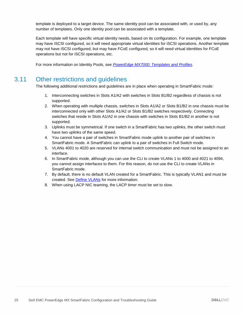
3.11 Other restrictions and guidelines The following additional restrictions and guidelines are in place when operating in SmartFabric mode:
1. Interconnecting switches in Slots A1/A2 with switches in Slots B1/B2 regardless of chassis is not supported.
2. When operating with multiple chassis, switches in Slots A1/A2 or Slots B1/B2 in one chassis must be interconnected only with other Slots A1/A2 or Slots B1/B2 switches respectively. Connecting switches that reside in Slots A1/A2 in one chassis with switches in Slots B1/B2 in another is not supported.
3. Uplinks must be symmetrical. If one switch in a SmartFabric has two uplinks, the other switch must have two uplinks of the same speed.
4. You cannot have a pair of switches in SmartFabric mode uplink to another pair of switches in SmartFabric mode. A SmartFabric can uplink to a pair of switches in Full Switch mode.
5. VLANs 4001 to 4020 are reserved for internal switch communication and must not be assigned to an interface.
6. In SmartFabric mode, although you can use the CLI to create VLANs 1 to 4000 and 4021 to 4094, you cannot assign interfaces to them. For this reason, do not use the CLI to create VLANs in SmartFabric mode.
7. By default, there is no default VLAN created for a SmartFabric. This is typically VLAN1 and must be created. See Define VLANs for more information.
8. When using LACP NIC teaming, the LACP timer must be set to slow.

26 Dell EMC PowerEdge MX SmartFabric Configuration and Troubleshooting Guide
4 Creating a SmartFabric The general steps required to create a SmartFabric are:
1. Physically cable the MX chassis and upstream switches. 2. Define the VLANs. 3. Create the SmartFabric. 4. If needed, configure uplink port speed and breakout. 5. Create the Ethernet uplink. 6. Configure the upstream switch and connect uplink cables.
These steps make the following assumptions:
• All MX7000 chassis and management modules are cabled correctly and in a Multi-Chassis Management group.
• The VLTi cables between switches have been connected.
NOTE: All server, network, and chassis hardware has been updated to the latest firmware. See Appendix E for the minimum recommended firmware versions.
4.1 Physically cable MX chassis and upstream switches The first step in creating the SmartFabric is to cable the MX chassis and upstream switches.
• For Management Module cabling, see PowerEdge MX9002m Module Cabling. • For VLTi cabling of different IOM placements, see Figure 5, Figure 6, and Figure 7.
For information on cabling the MX chassis to the upstream switches, see the example topologies in Scenario 1, Scenario 2 and Scenario 3 in this document.
For further information on cabling in general, see Dell EMC PowerEdge MX Networking Architecture Guide and Dell EMC PowerEdge MX Series Fibre Channel Storage Network Deployment with Ethernet IOMs Guide.
4.2 Define VLANs Before creating the SmartFabric, the initial set of VLANs should be created. The first VLAN to be created should be the default, or native VLAN, typically VLAN 1. The default VLAN must be created for any untagged traffic to cross the fabric.
To define VLANs using the OME-M console, perform the following steps:
1. Open the OME-M console. 2. From the navigation menu, click Configuration > Networks. 3. In the Network pane, click Define. 4. In the Define Network window, complete the following:
a. Enter a name for the VLAN in the Name box. In this example, VLAN0010 was used. b. Optionally, enter a description in the Description box. In this example, the description was
entered as “Company A General Purpose”. c. Enter the VLAN number in the VLAN ID box. In this example, 10 was entered. d. From the Network Type list, select the desired network type. In this example, General
Purpose (Bronze) was used. e. Click Finish.

27 Dell EMC PowerEdge MX SmartFabric Configuration and Troubleshooting Guide
Defined VLAN list
Figure 10 shows VLAN 1 and VLAN 10 after being created using the steps above.
4.3 Create the SmartFabric To create a SmartFabric using the OME-M console, perform the following steps:
1. Open the OME-M console. 2. From the navigation menu, click Devices > Fabric. 3. In the Fabric pane, click Add Fabric. 4. In the Create Fabric window, complete the following:
a. Enter a name for the fabric in the Name box. In this example, SmartFabric was entered. b. Optionally, enter a description in the Description box. In this example, the description was
entered as “SmartFabric using MX9116n/MX7116n in Fabric A”. c. Click Next. d. From the Design Type list, select the appropriate type. In this example, “2x MX9116n Fabric
Switching Engine in different chassis” was selected. e. From the Chassis-X list, select the first MX7000 chassis. f. From the Switch-A list, select Slot-IOM-A1. g. From the Chassis-Y list, select the second MX7000 chassis to join the fabric. h. From the Switch-B list, select Slot-IOM-A2. i. Click Next. j. On the Summary page, verify the proposed configuration and click Finish.
NOTE: From the Summary window a list of the physical cabling requirements can be printed.

28 Dell EMC PowerEdge MX SmartFabric Configuration and Troubleshooting Guide
SmartFabric deployment design window
The SmartFabric deploys. This process can take several minutes to complete. During this time all related switches will be rebooted, and the operating mode changed to SmartFabric mode.
NOTE: After the fabric is created, the fabric health will be critical until at least one uplink is created.
Figure 12 shows the new SmartFabric object and some basic information about the fabric.
SmartFabric post-deployment without defined uplinks
4.4 Configure uplink port speed or breakout, if needed If the uplink ports need to be reconfigured to a different speed or breakout setting, you must do that before creating the actual uplink.
To configure the Ethernet breakout on port groups using OME-M Console, perform the following steps:
1. Open the OME-M console. 2. From the navigation menu, click Devices > I/O Modules. 3. Select the switch you want to manage. In this example, a MX9116n FSE in slot IOM-A1 is selected. 4. Choose Hardware > Port Information. 5. In the Port Information pane, choose the desired port-group. In this example port-group1/1/13 is
selected.

29 Dell EMC PowerEdge MX SmartFabric Configuration and Troubleshooting Guide
NOTE: Prior to choosing the breakout type, you must change the Breakout Type to HardwareDefault and then select the desired configuration. If the desired breakout type is selected prior to setting HardwareDefault, an error will occur.
6. Choose Configure Breakout. In the Configure Breakout dialog box, select HardwareDefault. 7. Click Finish.
First set the breakout type to HardwareDefault
8. Once the job is completed, choose Configure Breakout. In the Configure Breakout dialog box,
select the required Breakout Type. In this example, the Breakout Type for port-group1/1/13 is selected as 1x40GE. Click Finish.
Select the desired breakout type
9. Configure the remaining breakout types on additional uplink port groups as needed.
4.5 Create the Ethernet uplinks NOTE: To change the port speed or breakout configuration, see Section 4.4 and make those changes before creating the uplinks.
After initial deployment, the new fabric shows Uplink Count as ‘zero’ and shows a warning ( ). The lack of a fabric uplink results in a failed health check ( ). To create the uplink, follow these steps:
1. Open the OME-M console. 2. From the navigation menu, click Devices > Fabric. 3. Click on the fabric name. In this example, SmartFabric is selected.

30 Dell EMC PowerEdge MX SmartFabric Configuration and Troubleshooting Guide
4. In the Fabric Details pane, click Uplinks. 5. Click on the Add Uplinks button. 6. In the Add Uplink window complete the following:
a. Enter a name for the uplink in the Name box. In this example, Uplink01 is entered. b. Optionally, enter a description in the Description box. c. From the Uplink Type list, select the desired type of uplink. In this example, Ethernet is selected. d. Click Next. e. From the Switch Ports list, select the uplink ports on both the Mx9116n FSEs. In this example,
ethernet 1/1/41 and ethernet 1/1/42 are selected for both MX9116n FSEs. f. From the Tagged Networks list, select the desired tagged VLANs. In this example, VLAN0010
is selected. g. From the Untagged Network list, select the untagged VLAN. In this example, VLAN0001 is
selected.
Create Ethernet uplink
h. Click Finish. At this point, SmartFabric creates the uplink object and the status for the fabric changes to OK .

31 Dell EMC PowerEdge MX SmartFabric Configuration and Troubleshooting Guide
4.6 Configure the upstream switch and connect uplink cables The upstream switch ports must be configured in a single LACP LAG. This document provides three example configurations:
• Scenario 1: SmartFabric deployment with Dell EMC PowerSwitch Z9100-ON upstream switches • Scenario 2: SmartFabric connected to Cisco Nexus 3232C switches • Scenario 3: SmartFabric connected to Cisco ACI leaf switches

32 Dell EMC PowerEdge MX SmartFabric Configuration and Troubleshooting Guide
5 Deploying a server
5.1 Server preparation The examples in this guide use a reference server of a Dell EMC PowerEdge MX740c compute sled with QLogic (model QL41262HMKR) Converged Network Adapters (CNAs) installed. CNAs are required to achieve FCoE connectivity. Use the steps below to prepare each CNA by setting them to factory defaults (if required) and configuring NIC partitioning (NPAR).
NOTE: iDRAC steps in this section may vary depending on hardware, software and browser versions used. See the Installation and Service Manual for your PowerEdge server for instructions on connecting to the iDRAC. From the link, select your server, then Manuals and documents.
5.1.1 Reset server CNAs to factory defaults Reset the CNAs to their factory defaults using the steps in this section. Resetting CNAs to factory default is only necessary if the CNAs installed have been modified from their factory default settings.
1. From the OME-M console, select the server to use to access the storage. 2. Launch the server Virtual Console. 3. From the Virtual Console, select Next Boot then BIOS Setup. 4. Reboot the server. 5. From the System Setup Main Menu, select Device Settings. 6. From the Device Settings page, select the first CNA port. 7. From the Main Configuration page, click the Default button. 8. Click Yes to load the default settings, and then click OK. 9. Click Finish. Notice if a message indicates a reboot is required for changes to take effect. 10. Click Yes to save changes, then click OK. 11. Repeat the steps in this section for each CNA port listed on the Device Settings page.
If required per step 9, reboot the system and return to System Setup to configure NIC partitioning.
5.1.2 Configure NIC partitioning on CNAs In this section, each QLogic CNA port is partitioned into one Ethernet and one FCoE partition.
NOTE: This is only done on CNA ports that carry converged traffic. In this example, these are the two 25GbE QLogic CNA ports on each server that attach to the fabric internally.
If the system is already in System Setup from the previous section, skip to step 4.
1. Using a web browser, connect to the iDRAC server and launch the Virtual Console. 2. From the Virtual Console, click Next Boot menu then select BIOS Setup. 3. Select the option to reboot the server. 4. On the System Setup Main Menu, select Device Settings. 5. Select the first CNA port. 6. Select Device Level Configuration. 7. Set the Virtualization Mode to NPAR, if not already set, and then click Back. 8. Select NIC Partitioning Configuration, Partition 1 Configuration, and click to set the NIC +
RDMA Mode to Disabled. 9. Click Back.

33 Dell EMC PowerEdge MX SmartFabric Configuration and Troubleshooting Guide
CNA partition 1 configuration
10. Select Partition 2 Configuration and set the NIC Mode to Disabled. 11. Set the FCoE Mode to Enabled, then click Back.
CNA partition 2 configuration
12. If present, select Partition 3 Configuration and set all modes to Disabled, then click Back. 13. If present, select Partition 4 Configuration and set all modes to Disabled, then click Back. 14. Click Back, and then Finish. 15. When prompted to save changes, click Yes and then click OK in the Success window. 16. Select the second CNA port and repeat steps in this section for port 2 17. After configuring port 2, click Finish, then Finish. 18. Click Yes to exit and reboot.
5.2 Create a server template A server template contains parameters extracted from a server and allows these parameters to be quickly applied to multiple compute sleds. The server template allows an administrator to associate VLANs to compute sleds. The templates contain settings for the following categories:
• Local access configuration • Location configuration • Power configuration • Chassis network configuration • Slot configuration • Setup configuration

34 Dell EMC PowerEdge MX SmartFabric Configuration and Troubleshooting Guide
NOTE: In SmartFabric mode, you must use a template to deploy a server and to configure the networking.
To create a server template, follow these steps:
1. Open the OME-M console. 2. From the navigation menu, click Configuration, then click Deploy. 3. From the center panel, click Create Template, then click From Reference Device to open the
Create Template window. 4. In the Template Name box, enter a name. In this example, “M740c with Intel mezzanine” is entered.
Create Template dialog box
5. Optionally, enter a description in the Description box, then click Next. 6. In the Device Selection section, click Select Device. 7. From the Select Devices window, choose the server previously configured, then click Finish. 8. From the Elements to Clone list, select all the elements, and then click Finish.

35 Dell EMC PowerEdge MX SmartFabric Configuration and Troubleshooting Guide
Select the elements to clone
A job starts, and the new server template displays on the list. When complete, the Completed successfully status displays.
5.3 Create identity pools Dell EMC recommends the use of identity pools. The steps below demonstrate creating an Ethernet identity pool with 255 MAC Addresses.
1. Open the OME-M console. 2. From the navigation menu, click Configuration > Identity Pools. 3. Click Create. 4. In the Create Identity Pool window, complete the following:
a. Enter a name in the Pool Name box. b. Optionally, enter a description in the Description box. c. Click Next. d. Select the Include ethernet virtual MAC Addresses option. e. Enter the first address in the Starting MAC Address box. f. Enter the number in the Number of Virtual MAC Identities box. g. Click Finish.
In this example, Ethernet ID pool is entered in Pool Name Box and 255 is entered in Virtual MAC Identities box.

36 Dell EMC PowerEdge MX SmartFabric Configuration and Troubleshooting Guide
5.4 Associate server template with networks After successfully creating a new template, associate the template with a network:
1. From the Deploy pane, select the template to be associated with VLANs. In this example, R740c with Intel mezzanine server template is selected.
2. Click Edit Network. 3. In the Edit Network window, complete the following:
a. Optionally, from the Identity Pool list, choose the desired identity pool. In this example, Ethernet ID Pool is selected.
b. For both ports, from the Untagged Network list, select the untagged VLAN. In this example, VLAN0001 is selected.
c. For both ports, from the Tagged Network list, select the tagged VLAN. In this example, VLAN0010 is selected.
d. Click Finish.
Figure 20 shows the associated networks for the server template.
Server template network settings
5.5 Deploy a server template To deploy the server template, complete the following steps:
1. From the Deploy pane, select the template to be deployed. In this example, R740c with Intel mezzanine server template is selected.
2. Click Deploy Template. 3. In the Deploy Template window, complete the following:
a. Click the Select button to choose which slots or compute sleds to deploy the template to. b. Select the Do not forcefully reboot the host OS option. c. Click Next. d. Choose Run Now e. Click Finish.
The interfaces on the MX9116n FSE are updated automatically. SmartFabric configures each interface with an untagged VLAN and any tagged VLANs. Additionally, SmartFabric deploys associated QoS settings. See Section 2.6.3 for more information.

37 Dell EMC PowerEdge MX SmartFabric Configuration and Troubleshooting Guide
6 SmartFabric operations This section elaborates the various operations that can be performed on the SmartFabric that has been created.
6.1 Viewing the fabric The SmartFabric created can be viewed using OME-M. The green check mark adjacent to the fabric name informs that the status of the fabric is healthy. In this example, the fabric created is named Fabric01.
1. Open the OME-M console. 2. From the navigation menu, click Devices > Fabric. 3. To view the Fabric components, select the fabric. This can also be achieved by clicking the View
Details button the right.
SmartFabric
Fabric components include Uplinks, Switches, Servers and ISL Links. Uplinks connect the MX9116n switches with upstream switches. In this example, the uplink is named as Uplink1.

38 Dell EMC PowerEdge MX SmartFabric Configuration and Troubleshooting Guide
Uplinks
Switches are the I/O Modules that are part of the fabric. In this example, the fabric has two MX9116n switches.
NOTE: Fabric Expander Modules are transparent and therefore do not appear on the Fabric Details page.
Switches
Servers are the compute sleds that are part of the fabric. In this example, two PowerEdge MX740c compute sleds are part of the fabric.
Servers

39 Dell EMC PowerEdge MX SmartFabric Configuration and Troubleshooting Guide
ISL Links are the VLT interconnects between the two switches. The ISL links should be connected on port groups 11 and 12 on MX9116n switches, and ports 9 and 10 on MX5108n switches. This is a requirement and failure to connect the defined ports will result in a fabric validation error.
ISL Links
6.2 Editing the fabric A fabric has four components:
• Uplinks • Switches • Servers • ISL Links
Editing the fabric discussed in this section includes editing the fabric name and description.
To edit the name of the fabric that was created, follow the steps below:
1. Open the OME-M console. 2. From the navigation menu, click Devices > Fabric. 3. On the right, Click the Edit button.

40 Dell EMC PowerEdge MX SmartFabric Configuration and Troubleshooting Guide
Edit fabric name and description
4. In the Edit Fabric dialog box, change the name and description as desired. Click Finish.
Edit Fabric dialog box
6.3 Editing uplinks Editing the uplinks on the created fabric is done using the following steps:
1. Open the OME-M console. 2. From the navigation menu, click Devices > Fabric. 3. Select the fabric. 4. Select the Uplink to edit and click Edit. In this example, Uplink1 is selected. 5. In the Edit Uplink dialog box, modify the Name and Description as desired.
NOTE: The uplink type cannot be modified once the fabric is created. If the uplink type needs to be changed after the fabric is created, delete the uplink and create a new uplink with the desired uplink type.

41 Dell EMC PowerEdge MX SmartFabric Configuration and Troubleshooting Guide
Edit Uplink dialog box
6. Click Next. 7. Edit the uplink ports on the MX switches that connects to the upstream switches. In this example,
ports 41 and 42 on the MX9116n switches that connects to upstream switches are displayed.
NOTE: Care should be taken to modify the uplink ports on both MX switches. Select the IOM to display the respective uplink switch ports.

42 Dell EMC PowerEdge MX SmartFabric Configuration and Troubleshooting Guide
Edit uplink ports and VLAN networks
8. If desired, modify the tagged and untagged VLANs. 9. Click Finish.
6.4 Editing VLANs on a deployed server The OME-M Console is used to add/remove VLANs on the deployed servers in a SmartFabric. The following illustrates the steps to add/remove VLANs on the deployed servers.
NOTE: Ensure that any new VLANs to be added are first defined in the Networks screen. See Define VLANs for more details.
1. Open OME-M Console. 2. From the navigation menu, click Devices > Fabric. 3. Select the fabric. 4. Select Servers from the left pane.

43 Dell EMC PowerEdge MX SmartFabric Configuration and Troubleshooting Guide
Add/remove VLANs
5. Choose the desired server. In this example PowerEdge MX740C with service tag 8XQP0T2 is selected.
6. Choose Edit Networks. 7. Modify the VLAN selections as required by defining the tagged and untagged VLANs. 8. Select VLANs on Tagged and Untagged Network for each Mezzanine card port. 9. Click Save.
Modify VLANs
NOTE: At this time, only one server can be selected at a time in the GUI.

44 Dell EMC PowerEdge MX SmartFabric Configuration and Troubleshooting Guide
7 Switch operations PowerEdge MX switches can be managed using the OME-M console. From the Switch Management page, you can view activity, health, and alerts, as well as perform operations such as power control, firmware update, and port configuration. Some of these operations can also be performed in Full Switch mode.
7.1 Switch management page overview To get to the switch management page, follow these steps:
1. Open the OME-M console 2. From the navigation menu, click Devices > I/O Modules. 3. Select the desired switch. In this example, MX9116n FSE IOM-A1 is selected.
IOM Overview page on OME-M
7.1.1 Switch overview The Overview page provides a convenient location to view pertinent data on the IOM such as:
• Chassis information • Recent Alerts • Recent Activity • IOM Subsystems

45 Dell EMC PowerEdge MX SmartFabric Configuration and Troubleshooting Guide
• Environment
The Power Control drop-down button provides three options:
• Power Off: Turns off the IOM • Power Cycle: Power cycles the IOM • System Reseat: Initiates a cold reboot of the IOM
Power Control button
The Blink LED drop down button provides an option to turn on or turn off the ID LED on the IOM. To turn on the ID LED, choose:
• Blink LED > Turn On
This activates a blinking blue LED and provides easy identification. To turn off the blinking ID LED, choose:
• Blink LED > Turn Off
Blink LED button

46 Dell EMC PowerEdge MX SmartFabric Configuration and Troubleshooting Guide
7.1.2 Hardware tab The Hardware tab provides information on the following IOM hardware:
• FRU • Device Management Info • Installed Software • Port Information
Hardware Tab
The Port Information provides useful operations such as:
• Configuring port-group breakout • Toggling the admin state of ports • Configuring MTU of ports • Toggling Auto Negotiation
Port Information

47 Dell EMC PowerEdge MX SmartFabric Configuration and Troubleshooting Guide
7.1.3 Firmware tab The Firmware tab provides options to manage the firmware on the IOM. The Dell Update Package (DUP) file is used to update the firmware of the IOM.
Firmware Tab
7.1.4 Alerts tab The Alert tab provides information on alerts and notifies the administrator. The advanced filter option can be leveraged to quickly filter out alerts. Various operations can be performed on an alert or several alerts such as:
• Acknowledge • Unacknowledged • Ignore • Export • Delete
Alerts Tab

48 Dell EMC PowerEdge MX SmartFabric Configuration and Troubleshooting Guide
7.1.5 Settings tab The Settings tab provides options to configure the following settings for the IOMs:
• Network • Management • Monitoring • Advanced Settings
Settings Tab
The Network option includes configuring IPv4, IPv6, DNS Server and Management VLAN settings.
Network Settings

49 Dell EMC PowerEdge MX SmartFabric Configuration and Troubleshooting Guide
The Management option includes setting the hostname and linuxadmin password.
NOTE: Although the GUI has the field name listed as Root Password, it denotes the linuxadmin password. For logging on to the CLI of the MX switch, use default credentials with username as admin and password as admin.
Management Settings
Monitoring provides options for SNMP settings.
Monitoring Settings
The Advanced Settings tab offers the option for time configuration replication and alert replication. Select the Replicate Time Configuration from Chassis check box to replicate the time settings configured in the chassis to the IOM. Select the Replicate Alert Destination Configuration from Chassis check box to replicate the alert destination settings configured in the chassis to the IOM.

50 Dell EMC PowerEdge MX SmartFabric Configuration and Troubleshooting Guide
Advanced Settings
7.2 Configure Ethernet switch ports from OME-M The MX switches can be accessed using the OME-M console. Various operations such as port breakout, altering the MTU size, enabling/disabling auto negotiation etc. Follow the below steps to gain insight into modifying various entities.
1. From the switch management page, choose Hardware > Port Information.
IOM Overview page on OME-M

51 Dell EMC PowerEdge MX SmartFabric Configuration and Troubleshooting Guide
Port information
2. To configure MTU, select the port listed under the respective port-group. 3. Click Configure MTU. Enter MTU size in bytes. 4. Click Finish.
Configure MTU
5. To configure Auto Negotiation, select the port listed under the respective port-group. Click Toggle AutoNeg. This will change the Auto Negotiation of the port to Disabled/Enabled. Click Finish.
Enable/Disable Auto Negotiation
6. To configure the administrative state (shut/no shut) of a port, select the port listed under the respective port-group. Click Toggle Admin State. This will toggle the port’s administrative state to Disabled/Enabled state.
7. Click Finish.

52 Dell EMC PowerEdge MX SmartFabric Configuration and Troubleshooting Guide
Toggle Admin State
7.3 Upgrading OS10EE Upgrading the IOMs in the fabric can be done using the OME-M console. The upgrade is carried out using the DUP file. The DUP is available for download from Support for Dell EMC Products.
Download DUP file for MX9116n FSE
When a single IOM is selected for firmware upgrade, the IOMs that are part of a fabric will also get their firmware updated.
NOTE: If an IOM is in SmartFabric mode, it leads to an upgrade of firmware of all IOMs that are part of the fabric. If an IOM is in Full Switch mode, firmware upgrade is completed only on the specific IOM selected.
To upgrade the IOMs that are part of a fabric, follow the steps below:
1. From the switch management page, choose Firmware > Update Firmware. In the Update Firmware dialog box, browse and select the appropriate DUP file.

53 Dell EMC PowerEdge MX SmartFabric Configuration and Troubleshooting Guide
Switch management page
Update firmware dialog box
2. Once the file is uploaded, select the check box next to the file and click Next. 3. Select Update Now and then click Finish.

54 Dell EMC PowerEdge MX SmartFabric Configuration and Troubleshooting Guide
Schedule update
The firmware upgrade job can be monitored by navigating to Monitor > Jobs > Select Job > View Details.
View the job for more details

55 Dell EMC PowerEdge MX SmartFabric Configuration and Troubleshooting Guide
8 Validating the SmartFabric deployment
8.1 View the MCM group topology The OME-M console can be used to show the physical cabling of the SmartFabric.
1. Open the OME-M console. 2. In the left pane click View Topology. 3. Click the lead chassis and then click Show Wiring. 4. The icons can be clicked to show cabling.
Figure 54 shows the current wiring of the SmartFabric.
SmartFabric cabling

56 Dell EMC PowerEdge MX SmartFabric Configuration and Troubleshooting Guide
8.2 View the SmartFabric status The OME-M console can be used to show the overall health of the SmartFabric.
1. Open the OME-M console. 2. From the navigation menu, click Devices > Fabric. 3. Select SmartFabric1 to expand the details of the fabric.
Figure 55 shows the details of the fabric.
Fabric status details
The Overview tab shows the current inventory, including switches, servers, and interconnects between the MX9116n FSEs in the fabric. Figure 56 shows the SmartFabric switch in a healthy state. Figure 57 shows the participating servers in a healthy state.
SmartFabric switch inventory

57 Dell EMC PowerEdge MX SmartFabric Configuration and Troubleshooting Guide
SmartFabric server inventory
Figure 58 shows the Topology tab and the VLTi created by the SmartFabric mode.
SmartFabric overview fabric diagram
Figure 59 displays the wiring diagram table from the Topology tab.
SmartFabric topology wiring diagram table

58 Dell EMC PowerEdge MX SmartFabric Configuration and Troubleshooting Guide
8.3 View port status The OME-M console can be used to show the port status. In this example, the figure displays ports for an MX9116n FSE.
1. Open the OME-M console. 2. From the navigation menu, click Devices > I/O Modules. 3. Select an IOM and click the View Details button to the right of the inventory screen. The IOM
overview for that device, displays. 4. From the IOM Overview, click Hardware. 5. Click to select the Port Information tab.
Figure 60 shows ethernet 1/1/1, 1/1/3, 1/71/1, and 1/72/1 in the correct operational status (Up). These interfaces correspond to the MX740c compute sleds in slots 1 and 2 in both chassis. The figure also shows the VLT connection (port channel 1000) and the uplinks (port channel 1) to the Z9100-ON leaf switches.
IOM Port Information

59 Dell EMC PowerEdge MX SmartFabric Configuration and Troubleshooting Guide
8.4 CLI commands
8.4.1 show switch-operating-mode Use the show switch-operating-mode command to display the current operating mode:
C140A1# show switch-operating-mode Switch-Operating-Mode : Smart Fabric Mode
8.4.2 show discovered-expanders The show discovered-expanders command is only available on the MX9116n FSE and displays the MX7116n FEMs service tag attached to the MX9116n FSEs and the associated port-group and virtual slot.
C140A1# show discovered-expanders Service Model Type Chassis Chassis-slot Port-group Virtual tag service-tag Slot-Id -------------------------------------------------------------------------- D10DXC2 MX7116n 1 SKY002Z A1 1/1/1 71 FEM
8.4.3 show unit-provision The show unit-provision command is only available on the MX9116n FSE and displays the unit ID and the provision and discovered name of the MX7116n FEM attached to the MX9116n FSE.
C140A1# show unit-provision Node ID | Unit ID | Provision Name | Discovered Name | State | ---------+---------+---------------------------------+-------| 1 | 71 | D10DXC2 | D10DXC2 | up |
8.4.4 show lldp neighbors The show lldp neighbors command shows information about LLDP neighbors. The iDRAC in PowerEdge MX compute sleds produce LLDP topology packets that contain specific information that the SmartFabric Services engine uses to determine the physical network topology regardless if a switch is in Full Switch or SmartFabric modes. For servers connected to switches in SmartFabric mode, the iDRAC LLDP topology feature is required. Without it, the fabric will not recognize the compute sled and the user will not be able to deploy networks to the sled.
The iDRAC MAC address can be verified by selecting iDRAC Settings > Overview > Current Network Settings from the iDRAC GUI of a compute sled. An example is shown as follows:
IOM Port Information

60 Dell EMC PowerEdge MX SmartFabric Configuration and Troubleshooting Guide
Alternately the iDRAC MAC information can be obtained from the System Information on the iDRAC Dashboard page.
IOM Port Information
Subsequently, viewing the LLDP neighbors shows the iDRAC MAC address in addition to the NIC MAC address of the respective mezzanine card.
C160A1(config)# do show lldp neighbors Loc PortID Rem Host Name Rem Port Id Rem Chassis Id -------------------------------------------------------------------------------- ethernet1/1/1 Not Advertised 98:03:9b:65:73:b2 98:03:9b:65:73:b4 ethernet1/1/1 iDRAC-8XQP0T2 8XQP0T2 NIC.Mezzanine.1A-1-1 d0:94:66:87:ab:40
---- OUTPUT TRUNCATED -----
In the example deployment validation of LLDP neighbors, Ethernet1/1/1, ethernet 1/1/3, and ethernet 1/1/71-1/1/72 represent the two MX740c sleds in one chassis. The first entry is the iDRAC for the compute sled. The iDRAC uses connectivity to the mezzanine card to advertise LLDP information. The second entry is the mezzanine card itself.
Ethernet 1/71/1 and ethernet 1/71/2 represent the MX740c compute sleds connected to the MX7116n FEM in the other chassis.
Ethernet range ethernet1/1/37-1/1/40 are the VLTi interfaces for the SmartFabric. Last, ethernet1/1/41-1/1/42 are the links in a port channel connected to the Z9100-ON leaf switches.
C140A1# show lldp neighbors Loc PortID Rem Host Name Rem Port Id Rem Chassis Id ---------------------------------------------------------------------------- ethernet1/1/1 iDRAC-CBMP9N2 CBMP9N2 NIC.Mezzanine.1A-1-1 d0:94:66:2a:07:2f ethernet1/1/1 Not Advertised 24:6e:96:9c:e3:50 24:6e:96:9c:e3:50 ethernet1/1/3 iDRAC-1S35MN2 1S35MN2 NIC.Mezzanine.1A-1-1 d0:94:66:29:fa:f4 ethernet1/1/3 Not Advertised 24:6e:96:9c:e5:48 24:6e:96:9c:e5:48 ethernet1/1/37 C160A2 ethernet1/1/37 20:04:0f:00:a1:9e

61 Dell EMC PowerEdge MX SmartFabric Configuration and Troubleshooting Guide
ethernet1/1/38 C160A2 ethernet1/1/38 20:04:0f:00:a1:9e ethernet1/1/39 C160A2 ethernet1/1/39 20:04:0f:00:a1:9e ethernet1/1/40 C160A2 ethernet1/1/40 20:04:0f:00:a1:9e ethernet1/1/41 Z9100-Leaf1 ethernet1/1/3 4c:76:25:e8:f2:c0 ethernet1/1/42 Z9100-Leaf2 ethernet1/1/3 4c:76:25:e8:e8:40 ethernet1/71/1 Not Advertised 24:6e:96:9c:e5:d8 24:6e:96:9c:e5:d8 ethernet1/71/1 iDRAC-CF52XM2 CF52XM2 NIC.Mezzanine.1A-1-1 d0:94:66:29:fe:b4 ethernet1/71/2 Not Advertised 24:6e:96:9c:e5:da 24:6e:96:9c:e5:da ethernet1/71/2 iDRAC-1S34MN2 1S34MN2 NIC.Mezzanine.1A-1-1 d0:94:66:29:ff:27
8.4.5 show qos system The show qos system command displays the QoS configuration applied to the system. The command is useful to verify the service policy created manually or automatically by a SmartFabric deployment.
C140A1# show qos system Service-policy (input): PM_VLAN ETS Mode : off
8.4.6 show policy-map Using the service policy from show qos system, the show policy-map type qos PM_VLAN command displays QoS policy details including associated class maps, for example, CM10, and QoS queue settings, qos-group 2.
C140A1# show policy-map type qos PM_VLAN Service-policy (qos) input: PM_VLAN Class-map (qos): CM10 set qos-group 2
8.4.7 show class-map The command show class-map displays details for all the configured class-maps. For example, the association between CM10 and VLAN 10 is shown.
C140A1# show class-map Class-map (application): class-iscsi Class-map (qos): class-trust Class-map (qos): CM10(match-any) Match: mac vlan 10 Class-map (qos): CM2(match-any
8.4.8 show vlt domain-id The show vlt domain-id command validates the VLT configuration status. The role of one switch in the VLT pair is primary (not shown), and its peer switch is assigned the secondary role. The VLT domain ID of 255 is automatically configured in SmartFabric mode. The VLTi link Status and VLT Peer Status must both be up. SmartFabric automatically configures the VLTi as port channel 1000.
MX9116n-1# show vlt 255 Domain ID : 255 Unit ID : 1 Role : secondary

62 Dell EMC PowerEdge MX SmartFabric Configuration and Troubleshooting Guide
Version : 1.0 Local System MAC address : 20:04:0f:00:b8:1e VLT MAC address : 20:04:0f:00:b8:1e IP address : fda5:74c8:b79e:1::1 Delay-Restore timer : 90 seconds Peer-Routing : Disabled Peer-Routing-Timeout timer : 0 seconds VLTi Link Status port-channel1000 : up VLT Peer Unit ID System MAC Address Status IP Address Version -------------------------------------------------------------------------------- 2 20:04:0f:00:9d:1e up fda5:74c8:b79e:1::2 1.0
8.4.9 show vlt domain-id vlt-port-detail The show vlt domain-id vlt-port-detail command shows the VLT port channel status for both VLT peers. The VLT in this example is connected to the Cisco ACI vPC. It is automatically configured in port channel 1, and it consists of two ports on each switch.
MX9116n-1# show vlt 255 vlt-port-detail vlt-port-channel ID : 1 VLT Unit ID Port-Channel Status Configured ports Active ports ------------------------------------------------------------------------------- * 1 port-channel1 up 2 2 2 port-channel1 up 2 2
8.4.10 show interface port channel summary The show interface port-channel summary command shows the LAG number (VLT port channel 1 in this example), the mode, status and ports used in the port channel.
MX9116n-1# show interface port-channel summary LAG Mode Status Uptime Ports 1 L2-HYBRID up 00:29:20 Eth 1/1/43 (Up) Eth 1/1/44 (Up)

63 Dell EMC PowerEdge MX SmartFabric Configuration and Troubleshooting Guide
9 Scenario 1 - SmartFabric deployment with Dell EMC PowerSwitch Z9100-ON upstream switches Figure 63 shows the production topology using a pair of Dell EMC PowerSwitch Z9100-ONs as upstream switches. This section walks through configuring the Z9100-ONs as well as validating the Z9100-ON configuration.
18 2014 1610 126 82 4 30 3226 2822 24
17 1913 159 115 71 3 29 3125 2721 23 33SFP+
34SFP+
Stack ID
EST
18 2014 1610 126 82 4 30 3226 2822 24
17 1913 159 115 71 3 29 3125 2721 23 33SFP+
34SFP+
Stack ID
EST
Z9100-ON Leaf 2
Z9100-ON Leaf 1
VLTi (100 GbE)Fabric uplink (100 GbE)FSE to FEM (200 GbE)FSE VLTi (200 GbE)
MX9116n FSEMX7116n FEM
MX7116n FEMMX9116n FSE
VLTi
VLTi
SmartFabric with Dell EMC PowerSwitch Z9100-ON leaf switches
NOTE: See Appendix A.10 for more information on QSFP28-DD cables.

64 Dell EMC PowerEdge MX SmartFabric Configuration and Troubleshooting Guide
9.1 Dell EMC PowerSwitch Z9100-ON switch configuration The following section outlines the configuration commands issued to the Dell EMC PowerSwitch Z9100-ON switches. The switches start at their factory default settings per Appendix D.4.
NOTE: The MX IOMs run Rapid Per-VLAN Spanning Tree Plus (RPVST+) by default. RPVST+ runs RSTP on each VLAN while RSTP runs a single instance of spanning tree across the default VLAN. The Dell EMC PowerSwitch Z9100-ON used in this example runs OS10EE and has RPVST+ enabled by default. See Spanning Tree Protocol recommendations for more information.
There are 4 steps to configure the Z9100-ON upstream switches:
1. Set the switch hostname and management IP address. 2. Configure the VLT between the switches. 3. Configure the VLANs. 4. Configure the port channels to connect to the MX switches.
Use the following commands to set the hostname, and to configure the OOB management interface and default gateway.
Z9100-ON Leaf 1 Z9100-ON Leaf 2
configure terminal hostname Z9100-Leaf1 interface mgmt 1/1/1 no ip address dhcp no shutdown ip address 100.67.162.35/24 management route 0.0.0.0/0 100.67.162.254
configure terminal hostname Z9100-Leaf2 interface mgmt 1/1/1 no ip address dhcp no shutdown ip address 100.67.162.34/24 management route 0.0.0.0/0 100.67.162.254
NOTE: Use spanning-tree {vlan vlan-id priority priority-value} command to set the bridge priority for the upstream switches. The bridge priority ranges from 0 to 61440 in increments of 4096. For example, to make Z9100-ON Leaf 1 as the root bridge for VLAN 10, enter the command spanning-tree vlan 10 priority 4096.
Configure the VLT between switches using the following commands. VLT configuration involves setting a discovery interface range and discovering the VLT peer in the VLTi.
Z9100-ON Leaf 1 Z9100-ON Leaf 2
interface range ethernet1/1/29-1/1/31 description VLTi no shutdown no switchport vlt-domain 1 backup destination 100.67.162.34 discovery-interface ethernet1/1/29-1/1/31
interface range ethernet1/1/29-1/1/31 description VLTi no shutdown no switchport vlt-domain 1 backup destination 100.67.169.35 discovery-interface ethernet1/1/29-1/1/31

65 Dell EMC PowerEdge MX SmartFabric Configuration and Troubleshooting Guide
Configure the required VLANs on each switch. In this deployment example, the VLAN used is VLAN 10.
Z9100-ON Leaf 1 Z9100-ON Leaf 2
interface vlan10 description “Company A General Purpose” no shutdown
interface vlan10 description “Company A General Purpose” no shutdown
Configure the port channels that connect to the downstream switches. The LACP protocol is used to create the dynamic LAG. Trunk ports allow tagged VLANs to traverse the trunk link. In this example, the trunk is configured allow VLAN 10.
Z9100-ON Leaf 1 Z9100-ON Leaf 2
interface port-channel1 description "To MX Chassis" no shutdown switchport mode trunk switchport trunk allowed vlan10 vlt-port-channel 1 interface ethernet1/1/1 description "To MX Chassis-1" no shutdown no switchport channel-group 1 mode active interface ethernet1/1/3 description "To MX Chassis-2" no shutdown no switchport channel-group 1 mode active end write memory
interface port-channel1 description "To MX Chassis" no shutdown switchport mode trunk switchport trunk allowed vlan10 vlt-port-channel 1 interface ethernet1/1/1 description "To MX Chassis-1" no shutdown no switchport channel-group 1 mode active interface ethernet1/1/3 description "To MX Chassis-2" no shutdown no switchport channel-group 1 mode active end write memory

66 Dell EMC PowerEdge MX SmartFabric Configuration and Troubleshooting Guide
9.2 Dell EMC PowerSwitch Z9100-ON validation This section contains validation commands for the Dell EMC PowerSwitch Z9100-ON leaf switches.
9.2.1 show vlt The show vlt command validates the VLT configuration status when the VLTi Link Status is up. The role of one switch in the VLT pair is primary, and its peer switch (not shown) is assigned the secondary role.
Z9100-Leaf1# show vlt 1 Domain ID : 1 Unit ID : 1 Role : primary Version : 1.0 Local System MAC address : 4c:76:25:e8:f2:c0 VLT MAC address : 4c:76:25:e8:f2:c0 IP address : fda5:74c8:b79e:1::1 Delay-Restore timer : 90 seconds Peer-Routing : Disabled Peer-Routing-Timeout timer : 0 seconds VLTi Link Status port-channel1000 : up VLT Peer Unit ID System MAC Address Status IP Address Version -------------------------------------------------------------------------------- 2 4c:76:25:e8:e8:40 up fda5:74c8:b79e:1::2 1.0
9.2.2 show lldp neighbors The show lldp neighbors command provides information about connected devices. In this case, ethernet1/1/1 and ethernet1/1/3 connect to the two MX9116n FSEs, C160A2 and C140A1. The remaining links, ethernet1/1/29 and ethernet 1/1/31, represent the VLTi connection.
Z9100-Leaf1# show lldp neighbors Loc PortID Rem Host Name Rem Port Id Rem Chassis Id ---------------------------------------------------------------- ethernet1/1/1 C160A2 ethernet1/1/41 20:04:0f:00:a1:9e ethernet1/1/3 C140A1 ethernet1/1/41 20:04:0f:00:cd:1e ethernet1/1/29 Z9100-Leaf2 ethernet1/1/29 4c:76:25:e8:e8:40 ethernet1/1/31 Z9100-Leaf2 ethernet1/1/31 4c:76:25:e8:e8:40
9.2.3 show spanning-tree brief The show spanning-tree brief command validates that STP is enabled on the leaf switches. All interfaces are forwarding (FWD), as shown in the Sts column.
Z9100-Leaf1# show spanning-tree brief Spanning tree enabled protocol rapid-pvst

67 Dell EMC PowerEdge MX SmartFabric Configuration and Troubleshooting Guide
VLAN 1 Executing IEEE compatible Spanning Tree Protocol Root ID Priority 32768, Address 2004.0f00.a19e Root Bridge hello time 2, max age 20, forward delay 15 Bridge ID Priority 32769, Address 4c76.25e8.f2c0 Configured hello time 2, max age 20, forward delay 15 Flush Interval 200 centi-sec, Flush Invocations 432 Flush Indication threshold 0 (MAC flush optimization is disabled) Interface Designated Name PortID Prio Cost Sts Cost Bridge ID PortID -------------------------------------------------------------------------------- port-channel1 128.2517 128 50 FWD 0 32768 2004.0f00 Interface Name Role PortID Prio Cost Sts Cost Link-type Edge -------------------------------------------------------------------------------- port-channel1 Root 128.2517 128 50 FWD 0 AUTO No VLAN 10 Executing IEEE compatible Spanning Tree Protocol Root ID Priority 32778, Address 4c76.25e8.e840 Root Bridge hello time 2, max age 20, forward delay 15 Bridge ID Priority 32778, Address 4c76.25e8.f2c0 Configured hello time 2, max age 20, forward delay 15 Flush Interval 200 centi-sec, Flush Invocations 5 Flush Indication threshold 0 (MAC flush optimization is disabled) Interface Designated Interface Designated Name PortID Prio Cost Sts Cost Bridge ID PortID -------------------------------------------------------------------------------- port-channel1 128.2517 128 50 FWD 1 32768 2004.0f00 Interface Name Role PortID Prio Cost Sts Cost Link-type Edge -------------------------------------------------------------------------------- port-channel1 Root 128.2517 128 50 FWD 1 AUTO No

68 Dell EMC PowerEdge MX SmartFabric Configuration and Troubleshooting Guide
10 Scenario 2 - SmartFabric connected to Cisco Nexus 3232C switches Figure 64 shows the production topology using a pair of Cisco Nexus 3232C as leaf switches. This section configures the Cisco Nexus 3232Cs and creating a SmartFabric with the corresponding uplinks.
Nexus 3232C Leaf 1 BCN
STS
ENV
S1 / 33
LS
1234
1 2 3 4 5 6 7 8 9 10 11 12 13 14 15 16 17 18 19 20 21 22 23 24 25 26 27 28 29 30 31 32
S2 / 34
BCN
STS
ENV
S1 / 33
LS
1234
1 2 3 4 5 6 7 8 9 10 11 12 13 14 15 16 17 18 19 20 21 22 23 24 25 26 27 28 29 30 31 32
S2 / 34
Nexus 3232C Leaf 2
Fabric uplink (100 GbE)FSE VLTi (200 GbE)FSE to FEM (200 GbE)vPC (100 GbE)
MX9116n FSEMX7116n FEM
MX7116n FEMMX9116n FSE
vPC Peer-Link
VLTi
SmartFabric with Cisco Nexus 3232C leaf switches
NOTE: See Appendix A.10 for more information on QSFP28-DD cables.

69 Dell EMC PowerEdge MX SmartFabric Configuration and Troubleshooting Guide
10.1 Cisco Nexus 3232C switch configuration The following section outlines the configuration commands issued to the Cisco Nexus 3232C leaf switches.
NOTE: While this configuration example is specific to the Cisco Nexus 3232C switch, the same concepts apply to other Cisco Nexus and IOS switches.
The switches start at their factory default settings, as described in Appendix D.5.
NOTE: The MX IOMs run Rapid per-VLAN Spanning Tree Plus (RPVST+) by default. Ensure the Cisco and Dell switches are configured to use compatible STP protocols. The mode of STP on the Cisco switch can be set using the command spanning-tree mode, which is shown below. See Spanning Tree Protocol recommendations for more information. In this deployment example, default VLAN is VLAN 1 and the created VLAN is VLAN 10. See Cisco Nexus 3000 Series NX-OS configuration guide for more details.
There are 4 steps to configure the 3232C upstream switches:
1. Set switch hostname, management IP address, enable features and spanning tree 2. Configure vPC between the switches 3. Configure the VLANs 4. Configure the downstream port channels to connect to the MX switches
Enter the following commands to set the hostname, enable required features, and enable RPVST spanning tree mode. Configure the management interface and default gateway.
Cisco Nexus 3232C Leaf 1 Cisco Nexus 3232C Leaf 2
configure terminal hostname 3232C-Leaf1 feature vpc feature lldp feature lacp spanning-tree mode rapid-pvst interface mgmt0 vrf member management ip address 100.67.162.201/24 vrf context management ip route 0.0.0.0/0 100.67.162.254
configure terminal hostname 3232C-Leaf2 feature vpc feature lldp feature lacp spanning-tree mode rapid-pvst interface mgmt0 vrf member management ip address 100.67.162.200/24 vrf context management ip route 0.0.0.0/0 100.67.162.254
Enter the following commands to create a virtual port channel (vPC) domain and assign the keepalive destination to the peer switch management IP. Then create a port channel for the vPC peer link and assign the appropriate switchport interfaces.

70 Dell EMC PowerEdge MX SmartFabric Configuration and Troubleshooting Guide
Cisco Nexus 3232C Leaf 1 Cisco Nexus 3232C Leaf 2
vpc domain 255 peer-keepalive destination 100.67.162.200 interface port-channel255 switchport switchport mode trunk vpc peer-link interface Ethernet1/29 description vPC Interconnect switchport switchport mode trunk channel-group 255 mode active no shutdown interface Ethernet1/31 description vPC Interconnect switchport switchport mode trunk channel-group 255 mode active no shutdown
vpc domain 255 peer-keepalive destination 100.67.162.201 interface port-channel255 switchport switchport mode trunk vpc peer-link interface Ethernet1/29 description vPC Interconnect switchport switchport mode trunk channel-group 255 mode active no shutdown interface Ethernet1/31 description vPC Interconnect switchport switchport mode trunk channel-group 255 mode active no shutdown
Enter the following commands to configure the port channels to connect to the downstream MX9116n FSEs. Then, exit configuration mode and save the configuration.
Cisco Nexus 3232C Leaf 1 Cisco Nexus 3232C Leaf 2
interface port-channel1 description To MX Chassis switchport switchport mode trunk switchport trunk allowed vlan 1,10 vpc 255 interface Ethernet1/1 description To MX Chassis 1 switchport switchport mode trunk switchport trunk allowed vlan 1,10 channel-group 1 mode active no shutdown interface Ethernet1/3 description To MX Chassis 2 switchport switchport mode trunk switchport trunk allowed vlan 1,10 channel-group 1 mode active no shutdown end copy running-configuration startup-configuration
interface port-channel1 description To MX Chassis switchport switchport mode trunk switchport trunk allowed vlan 1,10 vpc 255 interface Ethernet1/1 description To MX Chassis 1 switchport switchport mode trunk switchport trunk allowed vlan 1,10 channel-group 1 mode active no shutdown interface Ethernet1/3 description To MX Chassis 2 switchport switchport mode trunk switchport trunk allowed vlan 1,10 channel-group 1 mode active no shutdown end copy running-configuration startup-configuration

71 Dell EMC PowerEdge MX SmartFabric Configuration and Troubleshooting Guide
NOTE: If the connections to the MX switches do not come up, see Section 12.5.1 and Section 12.5.4 for troubleshooting steps.
Trunk ports on switches allow tagged traffic to traverse the links. All flooded traffic for the a VLAN will be sent across trunk ports to all the switches even if those switches do not have associated VLAN. This takes up the network bandwidth with unnecessary traffic. VLAN or VTP Pruning is the feature that can be used to eliminate this unnecessary traffic by pruning the VLANs.
Pruning restricts the flooded traffic to only those trunk ports with associated VLANs to optimize the usage of network bandwidth. If the existing environment is configured for Cisco VTP or VLAN pruning, ensure that the Cisco upstream switches are configured appropriately. See See Cisco Nexus 3000 Series NX-OS configuration guides for additonal information.
10.2 Configuration validation This section covers the validation of the Cisco Nexus 3232C leaf switches. For information about the Dell EMC Networking MX switch validation commands, see Section 8.4.
10.2.1 show vpc The show vpc command validates the vPC configuration status. The peer adjacency should be OK, with the peer should show as alive. The end of the command shows which VLANs are active across the vPC.
NX3232C-Leaf1# show vpc Legend: (*) - local vPC is down, forwarding via vPC peer-link vPC domain id : 255 Peer status : peer adjacency formed ok vPC keep-alive status : peer is alive Configuration consistency status : success Per-vlan consistency status : success Type-2 inconsistency reason : Consistency Check Not Performed vPC role : secondary, operational primary Number of vPCs configured : 1 Peer Gateway : Disabled Dual-active excluded VLANs : - Graceful Consistency Check : Enabled Auto-recovery status : Disabled Delay-restore status : Timer is off.(timeout = 30s) Delay-restore SVI status : Timer is off.(timeout = 10s) vPC Peer-link status --------------------------------------------------------------------- id Port Status Active vlans -- ---- ------ -------------------------------------------------- 1 Po255 up 1,10

72 Dell EMC PowerEdge MX SmartFabric Configuration and Troubleshooting Guide
vPC status ---------------------------------------------------------------------- id Port Status Consistency Reason Active vlans -- ---- ------ ----------- ------ ------------ 255 Po1 up success success 1,10
10.2.2 show vpc consistency-parameters The show vpc consistency-parameters command displays the configured values on all interfaces in the vPC. The displayed configurations are only those configurations that limit the vPC peer link and vPC from coming up.
NX3232C-Leaf1# show vpc consistency-parameters vpc 255 Legend: Type 1 : vPC will be suspended in case of mismatch Name Type Local Value Peer Value ------------- ---- ---------------------- ----------------------- STP Port Type 1 Normal Port Normal Port STP Port Guard 1 Default Default STP MST Simulate PVST 1 Default Default lag-id 1 [(1000, [(1000, 20-4-f-0-cd-1e, 1, 0, 20-4-f-0-cd-1e, 1, 0, 0), (7f9b, 0), (7f9b, 0-23-4-ee-be-ff, 80ff, 0-23-4-ee-be-ff, 80ff, 0, 0)] 0, 0)] mode 1 active active delayed-lacp 1 disabled disabled Speed 1 100 Gb/s 100 Gb/s Duplex 1 full full Port Mode 1 trunk trunk Native Vlan 1 1 1 MTU 1 1500 1500 Dot1q Tunnel 1 no no Switchport Isolated 1 0 0 vPC card type 1 N9K TOR N9K TOR Allowed VLANs - 1,10 1,10 Local suspended VLANs - - -

73 Dell EMC PowerEdge MX SmartFabric Configuration and Troubleshooting Guide
10.2.3 show lldp neighbors The show lldp neighbors command provides information about lldp neighbors. In this example, Eth1/1 and Eth1/3 are connected to the two MX9116n FSEs, C160A2 and C140A1. The remaining links, Eth1/29 and Eth1/31, represent the vPC connection.
NX3232C-Leaf1(config)# show lldp neighbors Capability codes: (R) Router, (B) Bridge, (T) Telephone, (C) DOCSIS Cable Device (W) WLAN Access Point, (P) Repeater, (S) Station, (O) Other Device ID Local Intf Hold-time Capability Port ID S3048-ON mgmt0 120 PBR ethernet1/1/45 C160A2 Eth1/1 120 PBR ethernet1/1/41 C140A1 Eth1/3 120 PBR ethernet1/1/41 NX3232C-Leaf2 Eth1/29 120 BR Ethernet1/29 NX3232C-Leaf2 Eth1/31 120 BR Ethernet1/31 Total entries displayed: 5
10.2.4 show spanning-tree summary The show spanning-tree summary command validates that STP is enabled on the leaf switches. All interfaces are shown as forwarding.
NX3232C-Leaf1# show spanning-tree summary Switch is in rapid-pvst mode Root bridge for: VLAN0010 Port Type Default is disable Edge Port [PortFast] BPDU Guard Default is disabled Edge Port [PortFast] BPDU Filter Default is disabled Bridge Assurance is enabled Loopguard Default is disabled Pathcost method used is short STP-Lite is disabled Name Blocking Listening Learning Forwarding STP Active ---------------------- -------- --------- -------- ---------- ---------- VLAN0001 0 0 0 2 2 VLAN0010 0 0 0 2 2 ---------------------- -------- --------- -------- ---------- ---------- 2 vlans 0 0 0 4 4

74 Dell EMC PowerEdge MX SmartFabric Configuration and Troubleshooting Guide
11 Scenario 3 - SmartFabric connected to Cisco ACI leaf switches This chapter covers deploying a PowerEdge MX SmartFabric connected to a Cisco ACI environment. By integrating PowerEdge MX into an ACI environment, compute resources in the MX environment can use ACI gateways and access ACI resources.
The Cisco ACI environment validated includes a pair of Nexus C93180YC-EX switches as leaf switches as shown in Figure 65. Both C93180YC-EX leafs are connected to a single Nexus C9336-PQ spine using 40GbE uplinks (not shown).
Connections from MX9116n FSE switches to C93180YC-EX leafs are 100GbE. These connections are shown in blue in Figure 65.
Smart Fabric connected to Cisco ACI leaf switches

75 Dell EMC PowerEdge MX SmartFabric Configuration and Troubleshooting Guide
11.1 Validated environment In this scenario, two MX7000 chassis are joined to an existing Cisco ACI environment. The MX chassis environment consists of two MX9116n FSEs, two MX7116n FEMs, and four MX compute sleds.
The connections between the ACI environment and the MX chassis are made using a double-sided multi-chassis link aggregation group (MLAG). The MLAG is called a vPC on the Cisco ACI side and a VLT on the PowerEdge MX side.
All devices in the validated environment covered in this chapter are connected as shown in Figure 66.
Validated SmartFabric and ACI environment
NOTE: The MX7116n FEMs are not shown in Figure 66 as they are transparent to the topology.

76 Dell EMC PowerEdge MX SmartFabric Configuration and Troubleshooting Guide
NOTE: No peer link is used between the Cisco ACI leaf switches. See the Cisco ACI documentation for more information. Cisco recommends a minimum of three Application Policy Infrastructure Controllers (APICs) in a production environment. For this validation effort, a single APIC, named APIC-1, is used.
All Dell EMC PowerEdge R730xd rack servers and MX compute sleds in this example are running VMware ESXi 6.7.0. VMs named “web,” “app,” and “db” on the ESXi hosts are running Ubuntu Linux guest operating systems. An optional jump box (shown in Figure 66), accessible over the OOB management network, is added to assist with vCenter configuration.
The existing Cisco ACI environment has two PowerEdge R730xd rack servers directly connected to the ACI leafs. These rack servers are in a VMware vSphere cluster, with a vCenter VM named mgmtvc01 located on R730xd-01 as shown in Figure 66.
Integrating the MX environment into the Cisco ACI environment enables the four MX compute sleds in the two chassis to join the existing VMware vSphere cluster. This allows all hosts and VMs to communicate using the relevant networks.
The environment uses the six networks shown in Table 6.
Networks used
VLAN ID VLAN name Description Network address Gateway address
1611 ESXi_Mgmt ESXi host in-band management 172.16.11.0/24 172.16.11.254
1612 vMotion VM migration 172.16.12.0/24 172.16.12.254
1613 vSAN Storage 172.16.13.0/24 172.16.13.254
1614 web VM data network 172.16.14.0/24 172.16.14.254
1615 app VM data network 172.16.15.0/24 172.16.15.254
1616 db VM data network 172.16.16.0/24 172.16.16.254
NOTE: While the VMware vMotion and vSAN networks are configured in this example, their use is out of scope for this guide.
VMs in the validated environment use the IP addresses shown in Table 7.
VM IP addresses
VM Name(s) VLAN name IP address(es)
mgmtvc01 ESXi_Mgmt 172.16.11.171
web01-web04 web 172.16.14.1-4
app01-app04 app 172.16.15.1-4
db01-db04 db 172.16.16.1-4

77 Dell EMC PowerEdge MX SmartFabric Configuration and Troubleshooting Guide
11.2 Cisco APIC configuration The Cisco APIC configuration includes the ports connected to the R730xd rack servers (and jump box, if used) and the vPC that connects to the MX9116n VLT port channel. This includes configuration of the ACI fabric interfaces, switches, and application-level elements such as ACI endpoint groups (EPGs) and bridge domains (BDs).
The networks used in the validated environment are shown in Table 8, along with the corresponding bridge domain, and application EPG names used in APIC configuration.
Validated environment network information
VLAN ID VLAN name Gateway IP
address/mask Bridge domain name Application EPG name
1611 ESXi_Mgmt 172.16.11.254/24 ESXiMgmtBD1 ESXiMgmtEPG1
1612 vMotion 172.16.12.254/24 vMotionBD1 vMotionEPG1
1613 vSAN 172.16.13.254/24 vSANBD1 vSANEPG1
1614 web 172.16.14.254/24 webBD1 webEPG1
1615 app 172.16.15.254/24 appBD1 appEPG1
1616 db 172.16.16.254/24 dbBD1 dbEPG1
In this deployment, EPGs are extended outside of the ACI fabric by mapping EPGs to external VLANs. This is so when a frame tagged with, VLAN 1611 for example, enters the ACI fabric, ACI knows that it belongs to the ESXi Management EPG and treats it accordingly.
ESXi Mgmt EPGESXi Mgmt BD
vMotion EPGvMotion BD
vSAN EPGvSAN BD
VLAN 1611
VLAN 1612
VLAN 1613
...
External devices
Bridge domains are associated with EPGs, which are mapped to external VLANs.

78 Dell EMC PowerEdge MX SmartFabric Configuration and Troubleshooting Guide
NOTE: APIC configuration steps used in the validated environment are provided in the attachment named Scenario 3 – APIC config steps.pdf. See the Cisco ACI documentation for detailed APIC configuration instructions.
11.3 Deploy a SmartFabric
11.3.1 Define VLANs The VLAN settings used during SmartFabric deployment for this environment are shown in Table 9.
SmartFabric VLAN settings
VLAN ID VLAN name Description Network type (QoS) Tagged/Untagged
1611 ESXi_Mgmt ESXi host in-band management
Hypervisor Management Tagged
1612 vMotion VM migration VM migration Tagged
1613 vSAN Storage Storage – Data Replication Tagged
1614 web VM data network General Purpose (Silver) Tagged
1615 app VM data network General Purpose (Silver) Tagged
1616 db VM data network General Purpose (Silver) Tagged VLANs for the SmartFabric are defined using the OME-M console as follows:
1. Open the OME-M console. 2. From the navigation menu, click Configuration > Networks. 3. In the Network pane, click Define. 4. In the Define Network window, complete the following:
• Enter the first VLAN name, for example, ESXi_Mgmt, in the Name box. • Optionally, enter a Description. • Enter the VLAN ID, for example, 1611. • Select the Network Type, for example, Hypervisor Management.
5. Click Finish. Repeat steps 3 and 5 for each VLAN.
NOTE: For information about network type and QoS group settings, see Section 2.6.3.
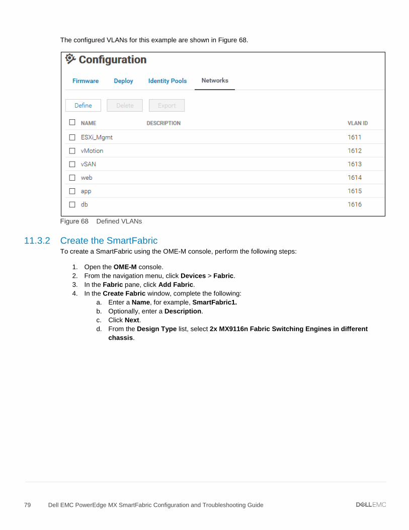
79 Dell EMC PowerEdge MX SmartFabric Configuration and Troubleshooting Guide
The configured VLANs for this example are shown in Figure 68.
Defined VLANs
11.3.2 Create the SmartFabric To create a SmartFabric using the OME-M console, perform the following steps:
1. Open the OME-M console. 2. From the navigation menu, click Devices > Fabric. 3. In the Fabric pane, click Add Fabric. 4. In the Create Fabric window, complete the following:
a. Enter a Name, for example, SmartFabric1. b. Optionally, enter a Description. c. Click Next. d. From the Design Type list, select 2x MX9116n Fabric Switching Engines in different
chassis.

80 Dell EMC PowerEdge MX SmartFabric Configuration and Troubleshooting Guide
e. From the Chassis-X list, select the first MX7000 chassis. f. From the Switch-A list, select Slot-IOM-A1. g. From the Chassis-Y list, select the second MX7000 chassis to join the fabric. h. From the Switch-B list, select Slot-IOM-A2.
SmartFabric deployment design window
i. Click Next. j. On the Summary page, verify the proposed configuration and click Finish.
The SmartFabric deploys. This process takes several minutes to complete. During this time, all related IOMs reload, the operating mode of the IOMs changes to SmartFabric, and the SmartFabric is created.
Figure 70 shows the new SmartFabric object.
SmartFabric after deployment before uplinks are created
NOTE: After creation, the SmartFabric shows the Uplink Count is 0 and the icon. The Health column displays the icon until uplinks are defined in the next section.

81 Dell EMC PowerEdge MX SmartFabric Configuration and Troubleshooting Guide
11.3.3 Define uplinks NOTE: To change the port speed or breakout configuration, see Section 4.4 and make those changes before creating the uplinks.
To define the uplinks from the MX9116n FSEs to the Cisco ACI leafs, follow these steps:
1. Open the OME-M console. 2. From the navigation menu, click Devices > Fabric. 3. Click the fabric name, for example, SmartFabric1. 4. In the left pane on the Fabric Details page, click Uplinks. 5. Click the Add Uplink button. In the Add Uplink window complete the following:
a. Enter a Name, for example, VLT01. b. Optionally, enter a description in the Description box. c. From the Uplink Type list, select Ethernet. d. Click Next. e. From the Switch Ports list, select the ports used in the uplink to the ACI leaf switches. In this
example, ethernet 1/1/43 and 1/1/44 are used on both MX9116n FSEs.
NOTE: Click the service tag of each MX9116n to expand their ports for selection as shown in Figure 71.
Click switch service tag to view ports

82 Dell EMC PowerEdge MX SmartFabric Configuration and Troubleshooting Guide
f. Under Tagged Networks, select the checkbox next to each VLAN that the uplink will be tagged. The uplink is a tagged member of all six VLANs in this example as shown in Figure 72.
g. If the uplink will be an untagged member of a VLAN, select the VLAN from the drop-down list next to Untagged Network. In this example, this is left at None.
NOTE: If the uplink is an untagged member of a VLAN, see the Cisco ACI documentation for setting the corresponding EPG to access (untagged) mode in ACI.
Tagged and untagged networks selected
h. Click Finish.
SmartFabric creates the uplink object. If the connected Cisco ACI vPC is configured correctly, as shown in the attachment Scenario 3 – APIC config steps.pdf, the uplink comes up and the status for the fabric changes to Ok on the Devices > Fabric page as shown in Figure 73.
SmartFabric status after uplink is created
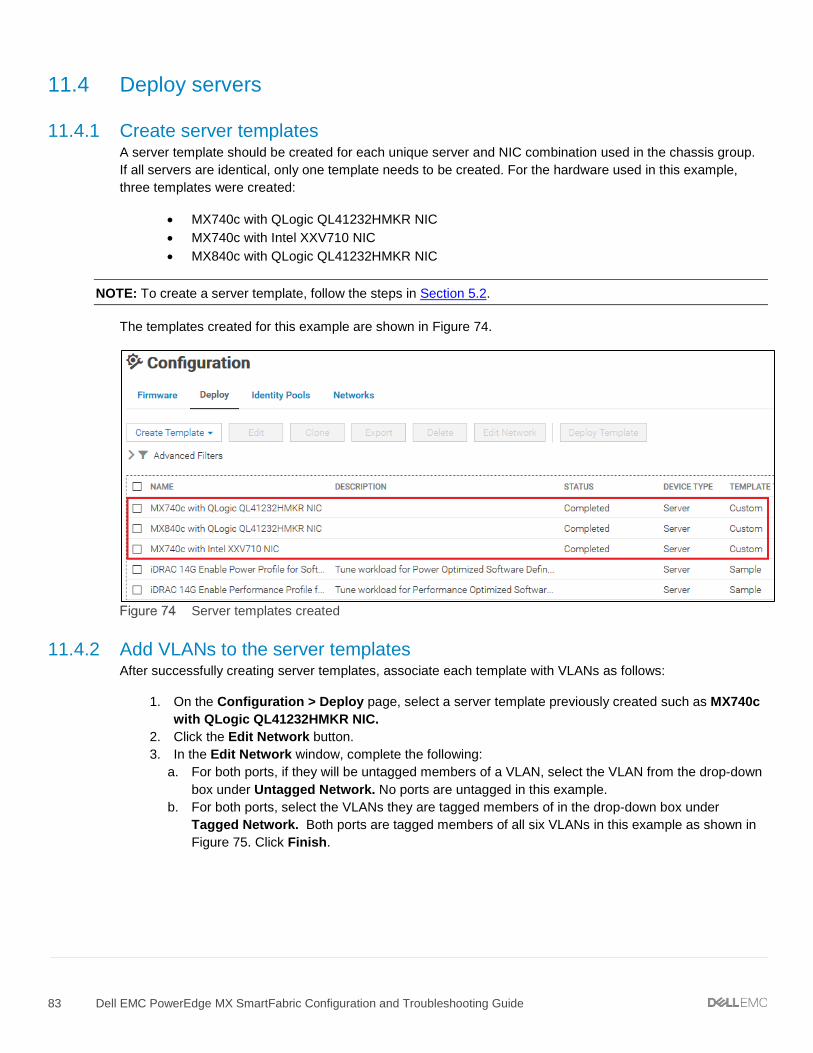
83 Dell EMC PowerEdge MX SmartFabric Configuration and Troubleshooting Guide
11.4 Deploy servers
11.4.1 Create server templates A server template should be created for each unique server and NIC combination used in the chassis group. If all servers are identical, only one template needs to be created. For the hardware used in this example, three templates were created:
• MX740c with QLogic QL41232HMKR NIC • MX740c with Intel XXV710 NIC • MX840c with QLogic QL41232HMKR NIC
NOTE: To create a server template, follow the steps in Section 5.2.
The templates created for this example are shown in Figure 74.
Server templates created
11.4.2 Add VLANs to the server templates After successfully creating server templates, associate each template with VLANs as follows:
1. On the Configuration > Deploy page, select a server template previously created such as MX740c with QLogic QL41232HMKR NIC.
2. Click the Edit Network button. 3. In the Edit Network window, complete the following:
a. For both ports, if they will be untagged members of a VLAN, select the VLAN from the drop-down box under Untagged Network. No ports are untagged in this example.
b. For both ports, select the VLANs they are tagged members of in the drop-down box under Tagged Network. Both ports are tagged members of all six VLANs in this example as shown in Figure 75. Click Finish.

84 Dell EMC PowerEdge MX SmartFabric Configuration and Troubleshooting Guide
VLANs added to server template
11.4.3 Deploy the server templates To deploy the server templates, complete the steps in Section 5.5

85 Dell EMC PowerEdge MX SmartFabric Configuration and Troubleshooting Guide
11.5 vCenter configuration overview The existing ACI environment has two PowerEdge R730xd rack servers connected to the ACI leafs. The rack servers are in a vSphere cluster named Management.
After the SmartFabric is deployed, MX compute sleds can communicate with the rack servers and the vCenter, mgmtvc01. The MX compute sleds are joined to the vSphere cluster by an administrator as shown in Figure 76.
Hosts and VMs used in the validated environment in a single vSphere cluster
NOTE: The VM locations in the topology are shown in Figure 66 at the beginning of this chapter.

86 Dell EMC PowerEdge MX SmartFabric Configuration and Troubleshooting Guide
A VDS named VDS-Mgmt, along with six distributed port groups, one for each VLAN, are used as shown in Figure 77.
VDS and port groups used in the validated environment
NOTE: For each port group in the VDS in this example, both uplinks are active and the load balancing method used is Route based on physical NIC load as recommended in VMware Validated Design Documentation. Detailed vCenter configuration is beyond the scope of this document.
NOTE: Cisco ACI supports VMware vCenter VDS integration where the APIC learns ESXi host locations using LLDP. With intermediate switches between ESXi hosts and ACI leaf switches, this is not possible without an LLDP relay mechanism. This feature is planned for a future OS10EE release.

87 Dell EMC PowerEdge MX SmartFabric Configuration and Troubleshooting Guide
11.6 Verify configuration This section covers methods to verify the SmartFabric and ACI environment is configured properly. For validating the MX side of the solution, see Section 8.
11.6.1 Cisco ACI validation
11.6.1.1 Verify vPC configuration Verify the vPC connection from the Cisco ACI fabric to the Dell MX SmartFabric VLT, shown in Figure 66, is up and properly configured to allow designated VLANs and EPGs. This is done as follows:
1. In the APIC GUI, go to Fabric > Inventory > Pod name > Leaf name > Interfaces > vPC Interfaces and drill down to the applicable port channel vPC policy group as shown in Figure 78.
2. Verify the port channel shows as lacp-active and that the Oper State shows as up.
Cisco ACI vPC port channel and interfaces
3. Verify that all leaf switch interfaces in the vPC, for example, eth1/51-52, are listed beneath the port channel and are also up.

88 Dell EMC PowerEdge MX SmartFabric Configuration and Troubleshooting Guide
4. With the port channel/vPC interface policy group selected in the left pane, click VLANs at the top of the right pane as shown in Figure 79.
Cisco ACI vPC port channel VLANs and EPGs
5. Verify that the port channel includes all required VLANs, and EPGs are mapped to the correct VLANs.
6. Repeat steps 1 through 5 for the remaining leaf switch.

89 Dell EMC PowerEdge MX SmartFabric Configuration and Troubleshooting Guide
11.6.1.2 Verify physical interface configuration The physical, host-connected, interfaces in the validated environment are those connected directly to the PowerEdge R730xd servers (and the jump box, if used) as shown in Figure 66.
Verify the physical interfaces from the Cisco ACI fabric to the servers are up and properly configured to allow designated VLANs and EPGs. This is done as follows:
1. In the APIC GUI, go to Fabric > Inventory > Pod 1 > Leaf name > Interfaces > Physical Interfaces as shown in Figure 80.
Cisco ACI physical interfaces
2. Verify that all required interfaces, for example, eth1/1-3, are up.

90 Dell EMC PowerEdge MX SmartFabric Configuration and Troubleshooting Guide
3. With an interface selected in the left navigational panel, click the VLANs tab in the navigation window as shown in Figure 81.
Cisco ACI interface VLANs and EPGs
4. Verify the interface includes all required VLANs and EPGs. Repeat for remaining interfaces as needed.
5. Repeat steps 1 through 4 for the remaining leaf switch.

91 Dell EMC PowerEdge MX SmartFabric Configuration and Troubleshooting Guide
11.6.1.3 Verify ACI is learning endpoints To verify ACI is learning endpoints, do the following:
1. In the APIC GUI, go to Tenants > Tenant name > Application Profiles > Application Profile name > Application EPGs > select an Application EPG.
2. Click the Operational tab in the navigation window as shown in Figure 82.
Cisco ACI endpoints in appEPG1
3. All learned endpoints for the selected EPG are displayed along with their VLAN, IP address, and interface.
4. Repeat the steps above for the remaining Application EPGs.

92 Dell EMC PowerEdge MX SmartFabric Configuration and Troubleshooting Guide
11.6.2 Verify connectivity between VMs In ACI, by default, communication flows freely within EPGs, but not between EPGs. To enable inter-EPG communication, contracts are configured on the APIC. This example is configured for unrestricted inter-EPG communication as shown in steps 17 through 19 in the Scenario 3 – APIC config steps.pdf attachment.
Connectivity is verified by pinging between the VMs shown in Figure 66. Since inter-EPG communication is allowed using configured contracts, all VMs can ping all other VMs in the topology.
Figure 83 shows the VM named app-01, located in a rack server, successfully pinging the VMs named web-03 and db-04, which are located on MX compute sleds.
Verifying connectivity between VMs

93 Dell EMC PowerEdge MX SmartFabric Configuration and Troubleshooting Guide
12 SmartFabric troubleshooting This section provides information on errors that might be encountered while working with a SmartFabric. Troubleshooting and remediation actions are also included to assist in resolving errors.
12.1 Troubleshooting errors encountered for port group breakout The creation of a SmartFabric involves executing specific steps in a recommended order. The SmartFabric deployment consists of four broad steps all completed using the OME-M console:
1. Create the VLANs to be used in the fabric. 2. Select switches and create the fabric based on the physical topology desired. 3. Create uplinks from the fabric to the existing network and assign VLANs to those uplinks. 4. Create and deploy the appropriate server templates to the compute sleds.
For cases where breakout of port groups is required, the breakout must be configured after the SmartFabric creation and before adding the uplinks.
CREATE VLANs
PORT BREAKOUT > HARDWARE DEFAULT
PORT BREAKOUT > SELECT DESIRED BREAKOUT TYPE
CREATE FABRIC
ADD UPLINKS
CREATE AND DEPLOY SERVER TEMPLATES
EXECUTE BASED ON BREAKOUT REQUIREMENT
EXECUTE WHEN BREAKOUT NOT REQUIRED
Recommended order of steps for port breakout while creating SmartFabric
You may encounter the following errors if the recommended order of steps is not followed:
1. Configuration of the breakout requires you to create the SmartFabric first. When attempting to configure breakout before creating a SmartFabric, the following error displays:

94 Dell EMC PowerEdge MX SmartFabric Configuration and Troubleshooting Guide
Error: I/O Module is not in fabric mode
2. Configuration of the breakout requires you to select the HardwareDefault breakout type first. If the breakout type is directly selected without first selecting HardwareDefault, the following error displays:
Error: interface fanout type is not hardware default
3. Once the uplinks are added, they are most often associated with tagged or untagged VLANs. When attempting to configure the breakout on the uplink port-groups after adding uplinks associated with VLANs to the fabric, the following error displays:
Error: Breakout failed

95 Dell EMC PowerEdge MX SmartFabric Configuration and Troubleshooting Guide
12.2 Troubleshooting Spanning Tree Protocol (STP) Spanning Tree Protocol (STP) prevents loops in the network. Loops can occur when multiple redundant parts are available between the switches. To prevent the network from going down due to loops, various flavors of STP are available. Initial introduction of STP evolved into various types. It is essential to ensure that network loops are prevented by using appropriate type of STP on the upstream switches as well as the MX9116n switches that are part of the MX SmartFabric.
12.2.1 Verify if STP is enabled on upstream switches STP is required when connecting a SmartFabric to the upstream network. Turning off Spanning Tree in the upstream switches will result in network loops and may cause downtime. Enable the appropriate STP type on the upstream switches.
12.2.2 Verify if type of STP is the same on MX and upstream switches Check the upstream switch if STP is enabled and verify that the type of STP matches the type of STP running on the MX switches. By default, the MX switches run RPVST+ as shown below:
OS10# show spanning-tree brief Spanning tree enabled protocol rapid-pvst VLAN 1 Executing IEEE compatible Spanning Tree Protocol ---- OUTPUT TRUNCATED -----
The following example shows the STP on the upstream switches, Cisco Nexus 3232C, is configured to run MST:
Nexus-3232C-Leaf1(config)# do show spanning-tree summary Switch is in mst mode (IEEE Standard) Root bridge for: MST0000 Port Type Default is disable ---- OUTPUT TRUNCATED -----
The recommended course of action is to change the STP type to RPVST+ on the upstream Cisco Nexus switches.
Nexus-3232C-Leaf1(config)# spanning-tree mode rapid-pvst Nexus-3232C-Leaf1(config)# do show spanning-tree summary Switch is in rapid-pvst mode ---- OUTPUT TRUNCATED -----
Another course of action in the above case can be to change the spanning tree type on the MX switches operating in SmartFabric mode to match the STP type on the upstream switches. This can be done using the OS10EE CLI. The options available on the type of STP are as follows:
OS10(config)# spanning-tree mode ? <rstp/mst/rapid-pvst> STP Protocol type
NOTE: MST is not currently supported in SmartFabric mode.

96 Dell EMC PowerEdge MX SmartFabric Configuration and Troubleshooting Guide
12.3 Verify VLT/vPC configuration on upstream switches Configuring a single VLT domain with Dell EMC Networking upstream switches or a single vPC domain with Cisco upstream switches is required. Creating two VLT/vPC domains may cause a network loop. See Scenario 1 and Scenario 2 for the topology used in the deployment example.
The following example shows a mismatch of the VLT domain IDs on VLT peer switches. To resolve this issue, ensure that a single VLT domain is used across the VLT peers.
Z9100-Leaf1# show vlt 1 Domain ID : 1 Unit ID : 1 Role : primary Version : 1.0 Local System MAC address : 4c:76:25:e8:f2:c0 Z9100-Leaf2# show vlt 30 Domain ID : 30 Unit ID : 1 Role : primary Version : 1.0
The following example shows a mismatch of the vPC domain IDs on vPC peer switches. To resolve this issue, ensure that a single vPC domain is used across the vPC peers.
Nexus-3232C-Leaf1# show vpc Legend: (*) - local vPC is down, forwarding via vPC peer-link vPC domain id : 1 Peer status : peer link is down vPC keep-alive status : peer is alive, but domain IDs do not match ---- OUTPUT TRUNCATED ----- 3232C-Leaf2# show vpc Legend: (*) - local vPC is down, forwarding via vPC peer-link vPC domain id : 255 Peer status : peer link is down vPC keep-alive status : peer is alive, but domain IDs do not match ---- OUTPUT TRUNCATED -----
12.4 Discovery of FEM and compute sleds The following can be verified if server or FEM discovery doesn’t happen:
• If there is no link indicated on the FSE port, toggle the auto-negotiation settings for that port. • Ensure that the compute sled is properly seated in the compute slot in the MX chassis. • Make sure that the compute sled is turned on. • Ensure that the drivers and firmware for BIOS, iDRAC, NICs and/or CNAs on the compute sleds are up to
date.

97 Dell EMC PowerEdge MX SmartFabric Configuration and Troubleshooting Guide
• Verify the Topology LLDP settings. This can be verified by selecting iDRAC Settings > Connectivity on the compute sled’s iDRAC GUI. Ensure that this setting is set to Enabled as shown in the figure below.
Ensure Topology LLDP is enabled
12.5 Troubleshooting uplink errors There might be additional settings enabled or disabled after uplinks are added to the fabric.
12.5.1 Toggle auto negotiation Enabling or disabling auto negotiation from the OME-M console can bring up the uplinks connecting to the upstream switches. For example, when deploying the SmartFabric with the Cisco Nexus 3232C (see Scenario 2), disable auto negotiation on uplink ports on the MX switches to bring the link up.
The OME-M console is used to disable/enable auto negotiation ports on MX switches. The following steps illustrate turning disabling auto negotiation on ports 41 and 42 of a MX9116n.
1. From switch management page, choose Hardware > Port Information. 2. Select the ports on which auto negotiation needs to be disabled. In this example, ports 1/1/41 and
port 1/1/42 are selected. 3. Click Toggle AutoNeg > Finish.

98 Dell EMC PowerEdge MX SmartFabric Configuration and Troubleshooting Guide
Toggle AutoNeg dialog box
12.5.2 Set uplink ports to administratively up The uplink ports on the switch might be administratively down. Enabling the uplink ports can be carried out from the OME-M console. The uplink ports can be administratively down when a port group breakout happens, especially for FC breakouts.
The OME-M console can be used to disable/enable the ports on MX switches. The following steps illustrate turning setting the administrative state on ports 41 and 42 of an MX9116n.
1. From switch management page, choose Hardware > Port Information. 2. Select the ports. In this example, ports 1/1/41 and port 1/1/42 are selected. 3. Click Toggle Admin State > Finish.
Toggle Administrative port state
12.5.3 Verify MTU size It is recommended to keep the same MTU size on ports connecting MX switches and the ports on the upstream switches and server NICs. To set the MTU size from the OME-M console, see Section 7.2.
12.5.4 Verify auto negotiation settings on upstream switches Verify the auto negotiation settings on the upstream switches. In case of where auto negotiation settings are modified, the links might not come up. Change the auto negotiation on upstream switches to resolve the issue.
For example, if the auto negotiation was disabled on the Cisco Nexus upstream switches, the setting can be turned on. To enable the auto-negotiation on an ethernet interface on Cisco Nexus switches, follow the below steps:
switch# configure terminal switch(config)# interface ethernet interface-number switch(config-if)# negotiate auto

99 Dell EMC PowerEdge MX SmartFabric Configuration and Troubleshooting Guide
The following example shows interface ethernet 1/2 that has auto negotiation enabled on the interface:
Nexus-3232C-Leaf1(config-if)# do show int eth 1/2 Ethernet1/2 is down (XCVR not inserted) admin state is down, Dedicated Interface Hardware: 40000/100000 Ethernet, address: 00fe.c8ca.f367 (bia 00fe.c8ca.f36c) MTU 1500 bytes, BW 100000000 Kbit, DLY 10 usec reliability 255/255, txload 1/255, rxload 1/255 Encapsulation ARPA, medium is broadcast auto-duplex, auto-speed Beacon is turned off Auto-Negotiation is turned on, FEC mode is Auto ---- OUTPUT TRUNCATED -----
12.5.5 Verify LACP The interface status of the upstream switches can provide valuable information for the link being down. The following example shows interfaces 1 and 3 on upstream Cisco Nexus switches as members of port channel 1:
3232C-Leaf2# show interface status -------------------------------------------------------------------------------- Port Name Status Vlan Duplex Speed Type -------------------------------------------------------------------------------- mgmt0 -- connected routed full 1000 -- Eth1/1 To MX Chassis 1 suspended trunk full 100G QSFP-100G-SR4 Eth1/2 -- xcvrAbsen routed auto auto -- Eth1/3 To MX Chassis 2 suspended trunk full 100G QSFP-100G-SR4 ---- OUTPUT TRUNCATED -----
Checking interface 1 reveals that the ports are not receiving the LACP PDUs as shown in the following example:
3232C-Leaf2# show int eth 1/1 Ethernet1/1 is down (suspended(no LACP PDUs)) admin state is up, Dedicated Interface Belongs to Po1 ---- OUTPUT TRUNCATED -----
NOTE: In Dell EMC Networking switches, use show interface status command to view the interfaces and associated status information. Use show interface ethernet interface number to view the interface details.
In this example, the errors listed above occurred because an uplink was not created on the fabric.

100 Dell EMC PowerEdge MX SmartFabric Configuration and Troubleshooting Guide
Fabric details
Fabric topology with no uplinks
The resolution is to add the uplinks and verify that the fabric turns healthy.
Healthy fabric

101 Dell EMC PowerEdge MX SmartFabric Configuration and Troubleshooting Guide
12.6 Troubleshooting FC/FCoE The following points can be verified while troubleshooting FC or FCoE errors:
• Ensure that the firmware and drivers are up to date on the CNAs. • Check the storage guide to ensure that the CNAs are supported by the storage used in the
deployment. For qualified support matrix, see elab navigator and Dell EMC Storage Compatibility Matrix for SC Series, PS Series and FS Series.
• Verify that port group breakout mode is appropriately configured. • Ensure that the FC port-groups broken out on the unified ports in MX9116n switches are made
administratively up once the ports are changed from Ethernet to FC. • MX9116n switches operating in SmartFabric mode support various commands to verify the
configuration. Use the following commands to verify FC configurations from MX9116n CLI:
OS10# show fc alias Show FC alias ns Show FC NS Switch parameters statistics Show FC Switch parameters switch Show FC Switch parameters zone Show FC Zone zoneset Show fc zoneset
• Use the following commands to verify FCoE configurations from MX9116n CLI:
OS10# show fcoe enode Show FCOE enode information
fcf Show FCOE fcf information sessions Show FCOE session information statistics Show FCOE statistics information system Show FCOE system information vlan Show FCOE vlan information
NOTE: For more information on FC and FCoE, see the OS10 Enterprise Edition User Guide 10.4.0E(R3S) and Dell EMC PowerEdge MX Series Fibre Channel Storage Network Deployment with Ethernet IOMs guide.

102 Dell EMC PowerEdge MX SmartFabric Configuration and Troubleshooting Guide
A Hardware overview This section briefly describes the hardware that is used to validate the deployment examples in this document. Appendix E contains a complete listing of hardware and software validated for this guide.
NOTE: While the steps in this document were validated using the specified Dell EMC Networking switches and operating systems, they may be leveraged for other Dell EMC Networking switch models utilizing the same networking OS version or later assuming the switch has the available port numbers, speeds, and types.
A.1 Dell EMC PowerEdge MX7000 chassis The PowerEdge MX7000 chassis has one of three control panel options for administration, up to six hot-pluggable, redundant, 3000-watt power supplies and up eight compute and storage sleds. Figure 94 shows the front of the chassis and the following installed components:
• One touchscreen LCD panel (optional) • Two Dell EMC PowerEdge MX740c sleds in slots one and two • Six blank inserts in slots three through eight
Dell EMC PowerEdge MX7000–front

103 Dell EMC PowerEdge MX SmartFabric Configuration and Troubleshooting Guide
The MX7000 includes three I/O fabrics. Fabrics A and B for Ethernet I/O Module (IOM) connectivity, and Fabric C for SAS and Fibre Channel (FC) connectivity. Each fabric provides two slots for redundancy.
Figure 95 shows the back of the PowerEdge MX7000 chassis configured with the following:
• One Dell EMC Networking MX9116n FSE shown in fabric slot A1 • One Dell EMC Networking MX7116n FEM shown in fabric slot A2 • Two Dell EMC PowerEdge MX9002m modules installed in management slots MM1 and MM2
Dell EMC PowerEdge MX7000–back
NOTE: Two PowerEdge MX7000 chassis with the hardware shown in Figure 94 and Figure 95 are used in this guide. Compute sled models and quantities vary in the examples.

104 Dell EMC PowerEdge MX SmartFabric Configuration and Troubleshooting Guide
A.2 Dell EMC PowerEdge MX740c compute sled The PowerEdge MX740c is a two-socket, full-height, single-width sled with impressive performance and scalability. It is ideal for dense virtualization environments and can serve as a foundation for collaborative workloads. An MX7000 chassis supports up to eight MX740c sleds.
PowerEdge MX740c key features include:
• Single-width slot design • Two CPU sockets • 24 DIMM slots of DDR4 memory • Boot options include BOSS-S1 or IDSDM • Up to six SAS/SATA SSD/HDD and NVMe PCIe SSDs • Two PCIe mezzanine card slots for connecting to network Fabric A and B • One PCIe mini-mezzanine card slot for connecting to storage Fabric C • iDRAC9 with Lifecycle Controller
Dell EMC PowerEdge MX740c sled with six 2.5-inch SAS drives

105 Dell EMC PowerEdge MX SmartFabric Configuration and Troubleshooting Guide
A.3 Dell EMC PowerEdge MX840c compute sled The PowerEdge MX840c, a powerful four-socket, full-height, double-width sled features dense compute and memory capacity and a highly expandable storage subsystem. It is the ultimate scale-up server that excels at running a wide range of database applications, substantial virtualization, and software-defined storage environments. An MX7000 chassis supports up to four MX840c sleds.
PowerEdge MX840c key features include:
• Dual-width slot design • Four CPU sockets • 48 DIMM slots of DDR4 memory • Boot options include BOSS-S1 or IDSDM • Up to eight SAS/SATA SSD/HDD and NVMe PCIe SSDs • Four PCIe mezzanine card slots for connecting to network Fabric A and B • Two PCIe mini-mezzanine card slots for connecting to storage Fabric C • iDRAC9 with Lifecycle Controller
Dell EMC PowerEdge MX840c sled with eight 2.5-inch SAS drives

106 Dell EMC PowerEdge MX SmartFabric Configuration and Troubleshooting Guide
A.4 Dell EMC PowerEdge MX9002m module The Dell EMC MX9002m module controls overall chassis power, cooling, and hosts the OME-M console. Two external Ethernet ports are provided to allow management connectivity and to connect additional MX7000 chassis in a single logical chassis. An MX7000 supports two MX9002m modules for redundancy. Figure 98 shows a single MX9002m module and its components.
Dell EMC PowerEdge MX9002m module
The following MX9002m module components are labeled in Figure 98.
1. Handle release 2. Gigabit Ethernet port 1 (Gb1) 3. Gigabit Ethernet port 2 (Gb2) 4. ID button and health status LED 5. Power status LED 6. Micro-B USB console port
NOTE: In this document, two MX9002m modules are used in each MX7000 chassis.

107 Dell EMC PowerEdge MX SmartFabric Configuration and Troubleshooting Guide
A.5 Dell EMC Networking MX9116n Fabric Switching Engine The Dell EMC Networking MX9116n FSE is a scalable, high-performance, low latency 25GbE switch purpose-built for the PowerEdge MX platform. The MX9116n FSE provides enhanced capabilities and cost-effectiveness for the enterprise, mid-market, Tier2 cloud, and NFV service providers with demanding compute and storage traffic environments.
In addition to 16 internal 25GbE ports, the MX9116n FSE provides the following external interfaces:
• Two 100GbE QSFP28 ports • Two 100GbE/100GFC QSFP28 unified ports • Twelve 200GbE QSFP28-Double Density (DD) ports
The two 100GbE QSFP28 ports provide Ethernet uplink connectivity. The two QSFP28 unified ports support SAN connectivity supporting both NPIV Proxy Gateway (NPG) and direct attach FC capabilities.
The QSFP28-DD ports provide capacity for additional uplinks, Virtual Link Trunking interconnect (VLTi) links, and connections to rack servers at 10GbE or 25GbE using breakout cables. Also, the QSFP28-DD ports provide fabric expansion connections for up to nine additional MX7000 chassis leveraging the MX7116n Fabric Expander Module in Fabric A and B. See Appendix A.10 for QSFP28-DD connector information.
Dell EMC Networking MX9116n FSE
The following MX9116n FSE components are labeled in Figure 99:
1. Express service tag 2. Storage USB port 3. Micro-B USB console port 4. Power and indicator LEDs 5. Module insertion/removal latch 6. Two QSFP28 ports 7. Two QSFP28 unified ports 8. Twelve QSFP28-DD ports
NOTE: In this document, two MX9116n FSEs are used – one in each MX7000 chassis.

108 Dell EMC PowerEdge MX SmartFabric Configuration and Troubleshooting Guide
A.6 Dell EMC Networking MX7116n Fabric Expander Module The Dell EMC Networking MX7116n Fabric Expander Module (FEM) acts as an Ethernet repeater, taking signals from attached compute sleds and repeating them to the associated lanes on the external QSFP28-DD ports. The MX7116n FEM provides eight internal 25GbE connections to the chassis and two external QSFP28-DD interfaces.
There is no operating system or switching ASIC on the MX7116n FEM, so it never requires an upgrade. There is also no management or user interface, making the MX7116n FEM maintenance-free.
Dell EMC Networking MX7116n FEM
The following MX7116n FEM components are labeled in Figure 100:
1. Express service tag 2. Supported optic LED 3. Power and indicator LEDs 4. Module insertion/removal latch 5. Two 200GbE QSFP28-DD fabric expander ports
NOTE: In this document, two MX7116n FEMs are used–one in each MX7000 chassis.
A.7 Dell EMC Networking MX5108n Ethernet switch The Dell EMC Networking MX5108n Ethernet switch is targeted at smaller PowerEdge MX7000 deployments using one or two chassis. While not a scalable switch, it still provides high-performance and low latency with a non-blocking switching architecture. The MX5108n provides line-rate 25GbE layer 2 and layer 3 forwarding capacity to all connected servers with no oversubscription.
In addition to eight internal 25GbE ports, the MX5108n provides the following external interfaces:
• One 40GbE QSFP+ port • Two 100GbE QSFP28 ports • Four 10GbE BASE-T ports
The ports can be used to provide a combination of network uplink, VLTi, or FCoE (FSB) connectivity. The MX5108n does not support NPG or direct attach FC capabilities.

109 Dell EMC PowerEdge MX SmartFabric Configuration and Troubleshooting Guide
Dell EMC Networking MX5108n
The following MX5108n components are labeled in Figure 101:
1. Luggage Tag 2. Storage USB Port 3. Micro-B USB console port 4. Power and indicator LEDs 5. Module insertion/removal latch 6. One QSFP+ port 7. Two QSFP28 ports 8. Four 10GbE BASE-T ports
NOTE: While the examples in this guide are specific to the MX9116n FSE and MX7116n FEM, the use of two MX5108n switches in a single chassis is supported for the solutions shown. Cabling options for the MX5108n will differ from the MX9116n/MX7116n as shown in the Dell EMC PowerEdge MX IO Guide.
A.8 PowerEdge MX7000 Fabrics I/O slots The PowerEdge MX7000 chassis includes two I/O fabrics: Fabric A and Fabric B. The vertically aligned compute sleds in slots one through eight connect to the horizontally aligned IOMs in slots A1, A2, B1, and B2. This orthogonal connection method results in a midplane-free design and allows the adoption of new I/O technologies without the burden of having to upgrade the midplane.
The MX740c supports two mezzanine cards, and the MX840c supports four mezzanine cards. Each mezzanine card connects to a pair of IOMs installed in the corresponding fabric slots as shown in Figure 102. For example, port one of mezzanine card A1 connects to fabric slot A1, containing an MX9116n FSE for example (not shown). Port two of mezzanine card A1 connects to fabric slot A2, containing an MX7116n FEM for example (not shown).

110 Dell EMC PowerEdge MX SmartFabric Configuration and Troubleshooting Guide
Dell EMC PowerEdge MX740c mezzanine cards
Table 10 shows the port mapping for fabric A. The MX9116n FSE in slot A1 maps dual-port mezzanine cards to odd-numbered ports. The MX7116n FEM, connected to the MX9116n FSE, maps to virtual ports with each port representing a compute sled attached to the MX7116n FEM.
Port mapping example for fabric A
MX7000 slot MX9116n FSE ports MX7116n FEM virtual ports
1 Ethernet 1/1/1 Ethernet 1/71/1
2 Ethernet 1/1/3 Ethernet 1/71/2
3 Ethernet 1/1/5 Ethernet 1/71/3
4 Ethernet 1/1/7 Ethernet 1/71/4
5 Ethernet 1/1/9 Ethernet 1/71/5
6 Ethernet 1/1/11 Ethernet 1/71/6
7 Ethernet 1/1/13 Ethernet 1/71/7
8 Ethernet 1/1/15 Ethernet 1/71/8
NOTE: In this document, only Fabric A is used.
A.9 Scalable fabric architecture overview A new concept with the PowerEdge MX platform is the scalable fabric architecture. A scalable fabric spans multiple chassis and allows them to behave like a single chassis from a networking perspective.
A scalable fabric consists of two main components, a pair of MX9116n FSEs in the first two chassis, and additional pairs of MX7116n FEMs in the remaining chassis. Each MX7116n FEM connects to the MX9116n FSE corresponding to its fabric and slot. All IOMs participating in the fabric are configured in either Full Switch or SmartFabric mode.

111 Dell EMC PowerEdge MX SmartFabric Configuration and Troubleshooting Guide
Figure 103 shows three (expandable to ten) MX7000 chassis in a single Scalable Fabric Architecture. The first two chassis each contain one MX9116n FSE and one MX7116n FEM. Chassis 3-10 each contain two MX7116n FEMs. All connections in the figure use QSFP28-DD connections.
Scalable Fabric example using Fabric A
In this document, a scalable fabric architecture is deployed across two PowerEdge MX7000 chassis. Both MX9116n FSEs operate in SmartFabric mode. This section provides an overview of the management network and the scalable fabric architecture used in this document.

112 Dell EMC PowerEdge MX SmartFabric Configuration and Troubleshooting Guide
Figure 104 shows the scalable fabric architecture network and how each of the MX9116n FSEs connect to a pair of leaf switches using QSFP28 cables. The MX9116n FSEs interconnect through a pair of QSFP28-DD ports. MX7116n FEMs connect to the MX9116n FSE in the other chassis as shown.
18 2014 1610 126 82 4 30 3226 2822 24
17 1913 159 115 71 3 29 3125 2721 23 33SFP+
34SFP+
Stack ID
EST
18 2014 1610 126 82 4 30 3226 2822 24
17 1913 159 115 71 3 29 3125 2721 23 33SFP+
34SFP+
Stack ID
EST
Z9100-ON Leaf 2
Z9100-ON Leaf 1
VLTi (100 GbE)Fabric uplink (100 GbE)FSE to FEM (200 GbE)FSE VLTi (200 GbE)
MX9116n FSEMX7116n FEM
MX7116n FEMMX9116n FSE
VLTi
VLTi
Scalable Fabric Architecture topology
NOTE: See Appendix A.10 for more information on QSFP28-DD cables.

113 Dell EMC PowerEdge MX SmartFabric Configuration and Troubleshooting Guide
A.10 QSFP28 double density connectors Quad Small Form-Factor Pluggable 28 Double Density, or QSFP28-DD connectors, expand on the QSFP28 pluggable form factor. By doubling the number of available lanes from four to eight, with each lane operating at 25 Gbps, the result is 200 Gbps for each connection.
NOTE: A QSFP28-DD transceiver is not compatible with a QSFP28 port due to the specifications required to lengthen the PCB connector to allow for the additional four lanes. However, a QSFP28 transceiver can be inserted into a QSFP28-DD port.
QSFP28-DD and QSFP28 physical interfaces
The MX9116n FSE supports direct attach cables (DAC), active optic cables (AOC), as well as multi-mode fiber (MMF) cables with supported Dell EMC Networking optics.
A.11 OOB management network Figure 106 shows a Dell EMC PowerSwitch S3048-ON used as an OOB management switch. Management ports from the leaf switches and the MX9002 modules connect to the S3048-ON as shown. Management ports on other equipment in the rack (not shown), such as PowerEdge server iDRACs, are also connected to the S3048-ON. Not shown is the S3048-ON connecting to the management network core.
NOTE: Shown for the leaf switch layer is a pair of Dell EMC PowerSwitch Z9100-ON switches. If using Cisco Nexus switches, management network configuration is identical.
For the S3048-ON management switch, all ports used are in Layer 2 mode and are in the default VLAN. Spanning Tree Protocol (STP) is enabled as a precaution against loops. Additional configuration is not required.

114 Dell EMC PowerEdge MX SmartFabric Configuration and Troubleshooting Guide
Management network
NOTE: See section 2.2 PowerEdge MX7000 Multi-Chassis Management groups in the Dell EMC PowerEdge MX Networking Architecture Guide for more information.
115 Dell EMC PowerEdge MX SmartFabric Configuration and Troubleshooting Guide
B OpenManage Enterprise Modular console The PowerEdge MX9002m module hosts the OME-M console. OME-M is the latest addition to the Dell OpenManage Enterprise suite of tools and provides a centralized management interface for the PowerEdge MX platform. OME-M console features include:
• End-to-end lifecycle management for servers, storage, and networking • A touch LCD for initial setup and error notification • Leverages iDRAC9 intelligent automation and security features • Manages one or multiple chassis from a single web or REST API leveraging multi-chassis
management (MCM) groups • OpenManage Mobile for configuration and troubleshooting including wireless server vKVM • Creation and deployment of SmartFabric topologies
B.1 PowerEdge MX9002m module cabling Multiple PowerEdge MX9002m modules are grouped to form domains called MCM groups. A single MCM group can include up to 10 chassis, where one is the lead and the remaining chassis are members. The OpenManage Enterprise Modular console supports a daisy chain topology using the redundant 1GbE ports on the MX9002m module.
An MCM group includes the following features:
• Provides the rollup health status of the OME-M chassis group • Automatically propagates lead chassis settings to member chassis
In addition to the two MX7000s each having a single connection to the S3048-ON management switch, additional inter-chassis cabling is needed. These additional 1GbE cables provide redundancy to all available MMs in both chassis. See section 2.2 PowerEdge MX7000 Multi-Chassis Management groups in the Dell EMC PowerEdge MX Networking Architecture Guide for more information on inter-chassis cabling of MMs.
B.2 PowerEdge MX7000 initial deployment Initial configuration may be done through the LCD touchscreen. If DHCP is not used, perform the following steps to assign a static IP address and gateway to each chassis:
1. Activate the LCD touchscreen by tapping the screen lightly. The Select Language screen displays. 2. Select the desired language, such as English. 3. Select Main Menu, and then Save. 4. Select Settings > Network Settings > Edit > IPv4 > Static IP. 5. Select Yes to change the IP settings from DHCP to Static. 6. Enter the required information in the following fields:
a. IP address b. Subnet mask c. Default gateway
7. Select Save. 8. Repeat steps 1 through 7 for each chassis.

116 Dell EMC PowerEdge MX SmartFabric Configuration and Troubleshooting Guide
On first logging into the OME-M console, the Chassis Deployment Wizard displayed. In this document, only MCM group definition settings are initially configured. All settings are optional and can be completed later by selecting Overview > Configure > Initial Configuration on the chassis page.
To complete the Chassis Deployment Wizard, complete the following steps:
1. In the Chassis Deployment Wizard window, click the Group Definition listing in the left navigational panel.
2. In the Group Definition pane, select the Create Group checkbox and complete the following: a. In the Group Name box, enter a name, for example, Group1. b. Optionally, enter a description in the Group Description box. c. Next to Onboarding Permissions, select Automatic. d. Select the All checkbox under Propagate Configuration to Members. e. Under Available Chassis, select the second MX7000 chassis and click Add Chassis. f. Under Current Members, confirm that the selected chassis is listed. g. Click Next.
3. On the Summary page, confirm the icon is displayed next to Group Definition Settings under Progress Status.
4. Click Submit.
After the window closes, click the Home button on the navigation pane. The group appears in the upper left corner of the page with all participating chassis members. It may take an additional few minutes for the secondary chassis to be added. When complete, both chassis should appear on the Home page with the status icon as shown in Figure 107.
Healthy MCM group

117 Dell EMC PowerEdge MX SmartFabric Configuration and Troubleshooting Guide
B.3 PowerEdge MX Ethernet I/O Module initial deployment All switches running OS10EE form a redundant management cluster that provides a single REST API endpoint to OME-M to manage all switches in a chassis or across all chassis in an MCM group. Figure 108 shows the PowerEdge MX networking IOMs in the MCM group. This page is accessed by selecting Devices > I/O Modules.
Each IOM can be configured directly from the OME-M console. Administrative tasks include:
• Viewing IOM-specific alerts • Power cycling the IOM • Configuring device management information • Configuring port breakout modes • Updating IOM firmware
OME-M console – I/O Modules page
IOMs are configured to receive their management IP address via DHCP by default. To optionally configure static IP addresses and hostnames on the MX9116n IOMs, do the following:
1. Open the OME-M console. 2. From the navigation menu, click Devices > I/O Modules. 3. Click IOM-A1 for the first MX9116n. 4. On the IOM-A1 page, click the Settings tab and expand Network. 5. Under IPv4 settings, uncheck the Enable DHCP box and specify a valid IP Address, Subnet Mask,
and Gateway. 6. Click Apply. 7. Expand the Management section and enter a Host Name in the field provided, for example,
MX9116n-1.

118 Dell EMC PowerEdge MX SmartFabric Configuration and Troubleshooting Guide
8. Click Apply. 9. Repeat steps 3-7 for the second MX9116n, IOM-A2.

119 Dell EMC PowerEdge MX SmartFabric Configuration and Troubleshooting Guide
C Rack-mounted switches This section covers the rack-mounted networking switches used in the examples in this guide.
C.1 Dell EMC PowerSwitch S3048-ON The Dell EMC PowerSwitch S3048-ON is a 1-Rack Unit (RU) switch with forty-eight 1GbE BASE-T ports and four 10GbE SFP+ ports. In this document, one S3048-ON supports out-of-band (OOB) management traffic for all examples.
Dell EMC PowerSwitch S3048-ON
C.2 Dell EMC PowerSwitch Z9100-ON The Dell EMC PowerSwitch Z9100-ON is a 1-RU multilayer switch with thirty-two QSFP28 ports supporting 10/25/40/50/100GbE and two 10GbE SFP+ ports. A pair of Z9100-ON switches is used as leaf switches in Scenario 1 in this guide.
Dell EMC PowerSwitch Z9100-ON
C.3 Cisco Nexus 3232C The Cisco Nexus 3232C is a 1-RU fixed form-factor 100GbE switch with thirty-two QSFP28 ports supporting 10/25/40/50/100GbE. A pair of Cisco Nexus 3232C switches is used as leaf switches in Scenario 2 in this guide.
C.4 Cisco Nexus C93180YC-EX The Cisco Nexus C93180YC-EX switch is a 1-RU switch with forty-eight 1/10/25GbE ports and six 40/100GbE ports. A pair of Cisco Nexus C93180YC-EX switches is used as Cisco ACI leaf switches in Scenario 3 in this guide.
C.5 Cisco Nexus C9336-PQ The Cisco Nexus C9336-PQ switch is a 2-RU switch with thirty-six 40GbE QSFP+ ports. One Cisco Nexus C9336-PQ switch is used as a Cisco ACI spine switch in Scenario 3 in this guide.

120 Dell EMC PowerEdge MX SmartFabric Configuration and Troubleshooting Guide
D Additional information
D.1 Delete a SmartFabric To remove the SmartFabric using the OME-M console, perform the following steps:
1. Open the OME-M console. 2. From the navigation menu, click Devices > Fabric. 3. Select SmartFabric. 4. Click the Delete button. 5. In the delete fabric dialog box click Yes.
All participating switches reboot to Full Switch mode.
NOTE: Any configuration not completed by the OME-M console is lost when switching between IOM operating modes.
D.2 Delete an MCM group To remove an MCM group using the OME-M console, perform the following steps:
1. Open the OME-M console. 2. In the MCM group pane, click the name of the lead chassis. 3. From the Configure menu, select Delete Group. 4. In the Delete Group dialog box, click Confirm.
At this point, the OME-M console removes the MCM group. To manage the chassis, use the individual IP addresses assigned to each.
D.3 Reset chassis using RACADM To reset the chassis to factory default settings, perform the following steps:
1. Connect to the MX9002m IP address using SSH. The default username is root, and the default password is calvin.
2. In the RACADM shell, run the racadm racresetcfg command. 3. The factory reset process is initiated, and a status message displays.
NOTE: The process takes several minutes to complete.
4. Optionally, after the reset process is complete, use the LCD screen to reassign a static IP address. See Section B.2 for more information.

121 Dell EMC PowerEdge MX SmartFabric Configuration and Troubleshooting Guide
D.4 Reset an OS10EE switch to factory defaults To reset OS10EE switches back to the factory default configuration, enter the following commands:
OS10# delete startup-configuration Proceed to delete startup-configuration [yes/no(default)]:yes OS10# reload System configuration has been modified. Save? [yes/no]:no Proceed to reboot the system? [confirm yes/no]:yes
The switch reboots with default configuration settings.
D.5 Reset Cisco Nexus 3232C to factory defaults To reset the Cisco Nexus 3232C switches to the factory default configuration, enter the following commands:
3232C# write erase Warning: This command will erase the startup-configuration. Do you wish to proceed anyway? (y/n) [n] y
After the next reboot the switch loads with default configuration settings.

122 Dell EMC PowerEdge MX SmartFabric Configuration and Troubleshooting Guide
E Validated components
E.1 Scenarios 1 and 2 The following tables include the hardware, software, and firmware used to configure and validate Scenario 1 and Scenario 2 in this document.
E.1.1 Dell EMC Networking switches
Dell EMC Networking switches and OS versions – Scenarios 1 and 2
Qty Item Version
2 Dell EMC PowerSwitch Z9100-ON leaf switches 10.4.0E(R3)
1 Dell EMC PowerSwitch S3048-ON OOB management switch 10.4.0E(R3P2)
E.1.2 Dell EMC PowerEdge MX7000 chassis and components
Dell EMC PowerEdge MX7000 chassis and components – Scenarios 1 and 2
Qty Item Version
2 Dell EMC PowerEdge MX7000 chassis -
4 Dell EMC PowerEdge MX740c sled (2 per chassis) -
4 Dell EMC PowerEdge M9002m modules (2 per chassis) 1.00
2 Dell EMC Networking MX9116n FSE (1 per chassis) 10.4.0E(R3)
2 Dell EMC Networking MX7116n FEM (1 per chassis) -
MX740c sled details – Scenarios 1 and 2
Qty per sled Item Firmware Version
1 Intel(R) Xeon(R) Silver 4114 CPU @ 2.20GHz -
12 16GB DDR4 DIMMs (192GB total) -
1 Boot Optimized Storage Solution (BOSS) Controller w/ 2x240GB SATA SSDs
2.6.13.2008
1 PERC H730P MX 25.5.3.0005
3 600GB SAS HDD -
1 Intel(R) Ethernet 25G 2P XXV710 mezzanine card 18.5.17
- BIOS 1.0.1
- iDRAC with Lifecycle Controller 3.20.20.20

123 Dell EMC PowerEdge MX SmartFabric Configuration and Troubleshooting Guide
E.1.3 Cisco Nexus switches
Nexus switches and OS versions – Scenarios 1 and 2
Qty Item Version
2 Cisco Nexus 3232C 7.0(3)I4(1)
E.2 Scenario 3 The following tables include the hardware, software, and firmware used to configure and validate Scenario 3 in this document:
E.2.1 Dell EMC Networking switches
Dell EMC Networking Switches and OS versions – Scenario 3
Qty Item OS Version
1 Dell EMC PowerSwitch S3048-ON OOB management switch 10.4.1.2
E.2.2 Dell EMC PowerEdge MX7000 chassis and components
Dell EMC PowerEdge MX7000 chassis and components – Scenario 3
Qty Item Version
2 Dell EMC PowerEdge MX7000 chassis -
3 Dell EMC PowerEdge MX740c sled -
1 Dell EMC PowerEdge MX840c sled -
4 Dell EMC PowerEdge M9002m modules (2 per chassis) 1.00.01
2 Dell EMC Networking MX9116n FSE (1 per chassis) 10.4.0E(R3S)
2 Dell EMC Networking MX7116n FEM (1 per chassis) -

124 Dell EMC PowerEdge MX SmartFabric Configuration and Troubleshooting Guide
MX740c sled details – Scenario 3
Qty per sled Item Version
2 Intel(R) Xeon(R) Silver 4114 CPU @ 2.20GHz -
12 16GB DDR4 DIMMs (192GB total) -
1 Boot Optimized Storage Solution (BOSS) S1 Controller w/ 1x120GB SATA SSD
2.6.13.3011
1 PERC H730P MX 25.5.5.0005
2 600GB SAS HDD -
1 Intel(R) Ethernet 2x25GbE XXV710 mezzanine card or
QLogic 2x25GbE QL41232HMKR mezzanine card
18.5.17 (Intel) or
14.07.07 (QLogic)
- BIOS 1.0.2
- iDRAC with Lifecycle Controller 3.20.20.20
VMware ESXi (Dell EMC Customized) 6.7.0 build 9484548 (A05)
MX840c sled details – Scenario 3
Qty/sled Item Version
2 Intel(R) Xeon(R) Gold 5118 CPU @ 2.30GHz -
2 32GB DDR4 DIMM -
1 Boot Optimized Storage Solution (BOSS) S1 Controller w/ 1x120GB SATA SSD
2.6.13.3011
1 PERC H730P MX 25.5.5.0005
2 600GB SAS HDD -
1 QLogic 2x25GbE QL41232HMKR mezzanine card 14.07.07
- BIOS 1.0.2
- iDRAC with Lifecycle Controller 3.20.20.20
VMware ESXi (Dell EMC Customized) 6.7.0 build 9484548 (A05)
E.2.3 Cisco ACI components
Cisco ACI components and OS versions – Scenario 3
Qty Item Version
1 Cisco APIC 3.2(3i)
1 Cisco Nexus C9336-PQ spine switch n9000-13.2(3i)
2 Cisco Nexus C93180YC-EX leaf switches n9000-13.2(3i)

125 Dell EMC PowerEdge MX SmartFabric Configuration and Troubleshooting Guide
F Technical resources Dell EMC Networking Guides
Dell EMC PowerEdge MX IO Guide
Dell EMC PowerEdge MX Network Architecture Guide
Dell EMC PowerEdge MX SmartFabric Deployment Video
Dell EMC PowerEdge MX SmartFabric Deployment with Cisco ACI Video
MX Port-Group Configuration Errors Video
MX Port-Group Configuration Video
Dell EMC OpenManage Enterprise-Modular Edition User's Guide v1.00.01
OS10 Enterprise Edition User Guide for PowerEdge MX IO Modules Release 10.4.0E R3S
Manuals and documents for Dell EMC PowerEdge MX7000
Manuals and documents for Dell EMC PowerSwitch MX9116n
Manuals and documents for Dell EMC PowerSwitch S3048-ON
Manuals and documents for Dell EMC PowerSwitch Z9100-ON

126 Dell EMC PowerEdge MX SmartFabric Configuration and Troubleshooting Guide
G Support and feedback Contacting Technical Support
Support Contact Information Web: http://www.dell.com/support
Telephone: USA: 1-800-945-3355
Feedback for this document
Dell EMC encourages readers to provide feedback on the quality and usefulness of this publication by sending an email to [email protected]

Dell EMC Configuration and Troubleshooting Guide Attachment
Dell EMC PowerEdge MX SmartFabric Configuration and Troubleshooting Guide Scenario 3 – Cisco APIC Configuration Steps
Abstract This document is an attachment to the Dell EMC PowerEdge MX SmartFabric Configuration and Troubleshooting Guide. It provides APIC configuration steps for the validated environment used in Scenario 3 of the guide. May 2019

2 Dell EMC PowerEdge MX SmartFabric Configuration and Troubleshooting Guide Scenario 3 – Cisco APIC Configuration Steps
Revisions Date Description
May 2019 Updated title, abstract, release date and revision table.
November 2018 Initial Release
The information in this publication is provided “as is.” Dell Inc. makes no representations or warranties of any kind with respect to the information in this publication, and specifically disclaims implied warranties of merchantability or fitness for a particular purpose. Use, copying, and distribution of any software described in this publication requires an applicable software license. © 2018 – 2019 Dell Inc. or its subsidiaries. All Rights Reserved. Dell, EMC, Dell EMC and other trademarks are trademarks of Dell Inc. or its subsidiaries. Other trademarks may be trademarks of their respective owners. Dell believes the information in this document is accurate as of its publication date. The information is subject to change without notice.

3 Dell EMC PowerEdge MX SmartFabric Configuration and Troubleshooting Guide Scenario 3 – Cisco APIC Configuration Steps
This document is an attachment to the Dell EMC PowerEdge MX SmartFabric Configuration and Troubleshooting Guide. It provides APIC configuration steps for the validated environment used in Scenario 3 of the guide.
These configuration steps begin after initial Cisco ACI deployment steps have been performed, including:
1. One or more Cisco APICs have been deployed. 2. Nexus leaf and spine switches have been discovered and registered with the APIC. The node ID
numbers and names used in this example are listed in Table 1.
APIC leaf and spine node IDs and names
Node ID Node name
101 Leaf1
102 Leaf2
201 Spine1
The networks used are shown in Table 2, along with the corresponding bridge domain and application EPG names used in APIC configuration.
Network information
VLAN ID VLAN name Gateway IP address/mask Bridge domain name Application EPG name
1611 ESXi_Mgmt 172.16.11.254/24 ESXiMgmtBD1 ESXiMgmtEPG1
1612 vMotion 172.16.12.254/24 vMotionBD1 vMotionEPG1
1613 vSAN 172.16.13.254/24 vSANBD1 vSANEPG1
1614 web 172.16.14.254/24 webBD1 webEPG1
1615 app 172.16.15.254/24 appBD1 appEPG1
1616 db 172.16.16.254/24 dbBD1 dbEPG1
The following steps were performed in the Cisco APIC GUI to configure APIC-1 for the validated environment.
1. Create a VLAN Pool:
a. Go to Fabric > Access Policies > Pools > VLAN b. Right click on VLAN and select Create VLAN Pool c. Name - VLANPool1 d. Allocation mode – Static e. Click +
i. VLAN Range - 1611-2000 ii. Allocation mode – Static Allocation iii. Role - External or On the wire encapsulations (default)
f. OK > Submit

4 Dell EMC PowerEdge MX SmartFabric Configuration and Troubleshooting Guide Scenario 3 – Cisco APIC Configuration Steps
2. Create a Physical Domain:
a. Go to Fabric > Access Policies > Physical and External Domains > Physical Domains b. Right click on Physical Domain and select Create Physical Domain c. Name - physDomain1 d. Assign VLANPool1 (created above) to the physical domain > Submit
3. Create an Attachable Access Entity Profile:
a. Go to Fabric > Access Policies > Policies > Global > Attachable Access Entity Profiles b. Right click on Attachable Access Entity Profiles and select Create Attachable Access Entity
Profile c. Name - AEP1 d. Domain Profile - associate it with physDomain1 (created above) e. Next > Finish
4. Create a Port Channel Policy:
a. Go to Fabric > Access Policies > Policies > Interface > Port Channel b. Right click on Port Channel and select Create Port Channel Policy c. Name - LACPPol1 d. Mode – LACP Active e. Control – keep default settings f. Submit
5. Create a vPC Interface Policy Group:
a. Go to Fabric > Access Policies > Interfaces > Leaf Interfaces > Policy Groups > VPC Interface
b. Right click on VPC Interface and select Create VPC Interface Policy Group c. Name - vPCPolGrp1 d. Attached entity profile – AEP1 (created above) e. Port Channel policy - LACPPol1 (created above) f. Submit
6. Create a Leaf Access Port Policy Group:
a. Go to Fabric > Access Policies > Interfaces > Leaf Interfaces > Policy Groups > Leaf Access Port
b. Right click on Leaf Access Port and select Create Leaf Access Port Policy Group c. Name - LeafHostPortGrp1 d. Attached entity profile – AEP1 (created above) e. Submit
7. Create a Leaf Interface Profile:
a. Go to Fabric > Access Policies > Interfaces > Leaf Interfaces > Profiles b. Right click on Profiles and select Create Leaf Interface Profile c. Name - LeafIntProf1 d. Create Access Port Selectors:
i. LeafHostSel1, contains directly connected host interfaces 1/1-3, associate to LeafHostPortGrp1 created above > Submit

5 Dell EMC PowerEdge MX SmartFabric Configuration and Troubleshooting Guide Scenario 3 – Cisco APIC Configuration Steps
ii. LeafvPCSel1, contains vPC interfaces 1/51-52, associate it to vPCPolGrp1 (created above) iii. Submit
8. Create a VPC Domain Policy:
a. Go to Fabric > Access Policies > Policies > Switch > VPC Domain b. Right click on VPC Domain and select Create VPC Domain Policy c. Name - vPCDom1 d. Submit
9. Create a VPC Explicit Protection Group:
a. Go to Fabric > Access Policies > Policies > Switch and select Virtual Port Channel default b. Leave Pairing Type set to Explicit (default) c. Next to Explicit VPC Protection Groups, click + d. Name - vPCExpProGrp1 e. ID - 101 f. VPC Domain Policy - select vPCDom1 (created above) g. Switch 1 – select the first leaf switch, 101/Leaf1 h. Switch 2 – select the second leaf switch, 102/Leaf2 i. Submit
10. Create a Leaf Profile:
a. Go to Fabric > Access Policies > Switches > Leaf Switches > Profiles b. Right click on Profiles and select Create Leaf Profile c. Name – LeafProf1 d. Next to Leaf Selectors, click + to create a Leaf Selector:
i. Name - LeafSel1 ii. Blocks - select switches 101 and 102 and click Update iii. Click Next iv. Interface Selector Profiles – select LeafIntProf1 (created above) > Finish
11. Create a Tenant:
a. Go to Tenants > Add Tenant b. Name - Tenant1 c. Submit
12. Create a VRF:
a. Go to Tenants > Tenant1 > Networking > VRFs b. Right click on VRFs and select Create VRF c. Name - VRF1 d. Uncheck Create a Bridge Domain and click Finish
13. Create Bridge Domains:
Note: Refer to Table 2 if needed.
Bridge domains are created for each VLAN as follows:

6 Dell EMC PowerEdge MX SmartFabric Configuration and Troubleshooting Guide Scenario 3 – Cisco APIC Configuration Steps
a. Go to Tenants > Tenant1 > Networking > Bridge Domains b. Right click on Bridge Domains and select Create Bridge Domain c. Enter the Name of the first bridge domain, webBD1 d. Next to VRF, select VRF1 (created above), and click Next e. Next to Subnets, click + f. Add the Gateway IP address and mask for the bridge domain - 172.16.14.254/24 and leave the
remaining values at their defaults g. Click OK > Next > Finish h. Repeat as needed for each VLAN, additional bridge domains created in this example are
appBD1, dbBD1, ESXiMgmtBD1, vMotionBD1, and vSANBD1.
14. Create an Application Profile:
a. Go to Tenants > Tenant1 > Application Profiles b. Right click on Application Profiles and select Create Application Profile c. Name – ap1 d. Submit
15. Create Application EPGs:
Note: Refer to Table 2 if needed.
a. Go to Tenants > Tenant1 > Application Profiles > ap1 > Application EPGs b. Right click on Application EPGs and select Create Application EPG c. Enter the Name of the first EPG, webEPG1 d. Next to Bridge Domain – select the associated bridge domain, webBD1 e. Click Finish f. Create a separate EPG for each of the remaining bridge domains, remaining EPG names used in
this example are appEPG1, dbEPG1, ESXiMgmtEPG1, vMotionEPG1, and vSANEPG1
16. Configure the Access Entity Profile with EPGs and VLANs:
Note: Refer to Table 2 if needed.
a. Go to Fabric > Access policies > Policies > Global > Attachable Access Entity Profiles b. Select AEP1 (created above) c. At bottom of page next to Application EPGs, click + d. For the first EPG, webEPG1:
i. Tenant – select Tenant1 ii. Application Profile - select ap1 iii. EPG - webEPG1 iv. Encap - vlan-1614 v. Primary Encap – leave blank vi. Mode – Trunk vii. Click Update
e. Repeat for all remaining EPGs using their associated VLAN IDs

7 Dell EMC PowerEdge MX SmartFabric Configuration and Troubleshooting Guide Scenario 3 – Cisco APIC Configuration Steps
To communicate between EPGs, contracts are created as follows:
17. Create a Contract Filter:
a. Go to Tenants > Tenant1 > Contracts > Filters b. Right click on Filters and select Create Filter c. Name - AllowAllFilter1 d. Next to Entries, click +
i. Name - Allow ii. EtherType - IP iii. Leave remaining items at their defaults and click Update > Submit
18. Create a Contract:
a. Go to Tenants > Tenant1 > Contracts > Standard b. Right click on Standard and select Create Contract c. Name - AllowAllContract1 d. Next to Subjects, click + e. Name - AllowAllSub1 f. Next to Filters, click + g. Under filter Name, select AllowAllFilter1 (created above) h. Click Update > OK > Submit
19. Apply the contract to the VRF:
a. Go to Tenant > Tenant1 > Networking > VRFs > VRF1 b. Expand VRF1 and select EPG collection for VRF c. Next to Provided Contracts, click +
i. Name – select AllowAllContract1 (created above) ii. Click Update
d. Next to Consumed Contracts, click +
i. Name – select AllowAllContract1 (created above) ii. Click Update
Use of 25GbE ports for leaf-to-MX9116n connections Note: If 100GbE ports on Nexus leaf switches are used to connect to MX9116 FSEs, disregard the following steps.
If 25GbE ports on Nexus leaf switches are used with breakout cables to connect to MX9116n FSEs, disable forwarding error correction (FEC) on the corresponding Nexus ports by following these two additional steps:
1. Create a Link Level policy:
a. Go to Fabric > Access Policies > Policies > Interface > Link Level b. Right click on Link Level and select Create Link Level Policy c. Name – NoFEC

8 Dell EMC PowerEdge MX SmartFabric Configuration and Troubleshooting Guide Scenario 3 – Cisco APIC Configuration Steps
d. Next to Forwarding Error Correction, select disable-FEC e. Leave other settings at their defaults and click Submit
2. Apply the Link Level policy to the vPC Interface Policy Group:
a. Go to Fabric > Access Policies > Interfaces > Leaf Interfaces > Policy Groups > VPC Interface.
b. Select the existing VPC Interface Policy Group, vPCPolGrp1 c. Next to Link Level Policy, select NoFEC (created above) d. Click Submit