Embed Size (px)
Citation preview
Eindhoven University of Technology
Faculty of Mechanical Engineering
Department of Production Engineering and Automation (WPA)
Defects and defect avoidancein cold forging.
M.A.J. de Vries
TUE-MSc thesis
maart 1993
Vfcode: D3 WPA reportnr.: 1485
Summary
The competitiveness of cold forging processes in relation to other manufacturingprocesses is good. To remain competitive, cold forging processes have to producedefect free products.
In practice there is a wide range of defects which occur during metal forming processes.
Fracture IS In most cases the only defect that immediately is recognized as one.Cracking is also the defect that has been researched most extensively. The Okamotoclassification of cracks is used to discuss the cracks and their causes. The main causefor cracks is a wrong tool geometry.
Surface imperfections find their main cause in an inadequate lubrication. Althoughthis kind of defect has not attracted much attention, it will become more important infuture.
Flow imperfections represent a wide range of defects, but they can be divided in:dimensional inaccuracies, shape inaccuracies and positional errors. The main causesfor these defects are a wrong designed tool and inadequate lubrication.
A method of dealing with these defects is of considerable interest, since the cost toindustry in terms of lost time and material is essentially proportional to the percentage of products being rejected.
In literature there are several manners mentioned to avoid defects. Statistical processcontrol and various physical modelling techniques are the methods that are alreadybeing frequently used in industry. Databases, expert systems and neural networkshowever, are not being used so often but they show great potential on defectavoidance.
A literature survey has been carried out on the subject of defects in cold forging. Thissurvey initially encompassed the literature of the last decade. In addition otherrelevant literature was consulted.
11
Samenvatting
In vergelijking met andere produktietechnieken zijn (massief) omvormprocessen zeerconcurrerend. Om concurrerend te blijven, moeten de omvormprocessen echterfoutloze produkten produceren.
In de praktijk kunnen er een groot aantal fouten aan de produkten optreden. Breukis in de meeste gevallen de enige fout die onmiddellijk wordt herkend als een fout.Daarnaast is breuk de fout waarnaar het meeste onderzoek is gedaan. De Okamotoclassificatie van breuken wordt gebruikt om de breuken en hun oorzaken te
evalueren. De belangrijkste oorzaak van breuk is een verkeerd gereedschapsontwerp.
OppervIakteafwijkingen worden meestal veroorzaakt door verkeerde smering.
AIhoeweI aan dit soort fouten niet veel aandacht is besteed, zullen ze belangrijkerworden in de nabije toekomst
Vloeiafwijkingen vertegenwoordigen een groot aantal fouten. Ze kunnen wordenverdeeld in maatonnauwkeurigheden, vormafwijkingen en plaatsafwijkingen. De
belangrijkste oorzaak voor deze fouten is een verkeerd ontworpen gereedschap enonvoldoende smering.
Een methode om afwijkingen te vermijden is van groot belang voor de industrie. Dekosten in termen van tijd- en materiaalverlies zijn nameIijk proportioneel aan dehoeveelheid afgekeurde produkten.
In de literatuur worden verschillende manieren genoemd om fouten te voorkomen.Statistische procescontrole en verschillende modellering technieken zijn de methodendie al regelmatig worden gebruikt in de industrie. Databases, expert systemen enneurale netwerken worden echter nog niet zo vaak gebruikt. Deze methoden tonenechter al grote mogelijkheden voor het vermijden van fouten.
Een literatuuronderzoek is gedaan naar het falen bij massiefomvormen en naar demanieren om afwijkingen te vermijden. Eerst is gezocht naar de literatuur, diegeschreven is in de Iaatste tien jaar, vervolgens naar andere relevante literatuur.
III
Eindstudieopdracht
Student:
Onderwerp:
Toelichting:
Omschrijving:
1)
2)
M.A.J. de Vries
Falen bij massief omvormen (Defects in cold forging).
Bij het massief omvormen kunnen veel verschillende fouten in het produkt
optreden. Voorbeelden hielVan zijn: breuk of scheulVorming, ongewenste op
pelVlakte ruwheid, onvlakheid, maatafwijkingen, enz.. Deze fouten maken bet
produkt waardeloos of maken een dure nabewerking noodzakelijk. Het is
daarom zaak om de faalcriteria en hun achtergronden te doorgronden.
Net zoals er veel fouten zijn, zijn er veel oorzaken. Enkele voorbeelden
hieIVan zijn: gereedschapsslijtage, slechte smering, eoz.. Ook de achtergronden
hielVan zijn interessant.
In drie fasen zal worden geprobeerd om inzicht te vergroten in de
belangrijkste fouten en oorzaken bij massief omvormen.
OpsteUen van een overzicht van de meest optredende fouten en bun oorzaken
bij massief omvormen. Dit wordt gedaan aan de band van een lite
ratuuronderzoek en gesprekken met bedrijven. Een stage van drie maanden
aan The University of Reading, zal een onderdeel van deze orienterende fase
zijn.
Analyse van een aantal van de belangrijkste faalcriteria door middel van
procesanalyses. De analyses zullen worden uitgevoerd met de methodes die
worden aangereikt bij technische plasticiteitsleer en beschikbare simulatie
pakketten. Ook zal er gebruik worden gemaakt van de dissertaties van P.J.
Bolt en W. Sillekens en de eindstudie van L. Joosten. Daamaast kan een
materiaalkundige analyse deel uitmaken van de analyse.
3) Afronding door middel van een verslag met daarin een overzicht van de
mogelijke fouten en de oplossingen hielVoor.
Plaats en Datum: Eindhoven 27 februari 1992
IV
Contents
Summary
Samenvatting
Eindstudieopdracht
Contents
ii
iii
IV
V
1
2
Introduction
Defects
2.1 Definitions2.2 Classifications
2.3 Fracture2.3.1 a-Crack
2.3.2 l3-crack
2.3.3 'Y-crack2.3.4 o-crack2.3.5 e-crack
2.3.6 t-crack2.3.7 TJ-crack2.3.8 K-crack2.3.9 Wcrack2.3.10 A-crack2.3.11 8-crack
2.4 Surface imperfections2.4.1 Plowing2.4.2 Tearing of weldments2.4.3 Galling2.4.4 Surface layer of severe plastic flow2.4.5 Surface roughening due to coarse grain size2.4.6 Remarks on surface imperfections and workpiece
lubrication
V
1
334
6
6
10101314
1516
16
17
18
19
19202021
2121
22
3
4
2.5 Flow imperfections2.5.1 Material stock
2.5.2 Billet preparation
2.5.3 Lubrication
2.5.4 Tools
2.5.5 Forming machine
2.5.6 Process and tool design
2.5.7 Product handling
2.5.8 Operational control
Defect avoidance3.1 Statistical process control3.2 Physical modelling
3.3 Mathematical modelling
3.4 Database
3.5 Expert system3.5.1 Evaluation of defects and causes of defects
3.5.2 Advantages and disadvantages
3.6 Neural networks
Conclusions and remarks
22
23
24242526
27
27
28
292931
32
33
3335
38
39
40
Literature
VI
41
1 Introduction
Nowadays manufacturing has claimed the largest single share of the gross nationalproduct, a measure which can be taken as an indication of the material well-being ofa countryllJ. This makes it evident that manufacturing should be competitive, on alocal as well as a global basis. Competitiveness can only be achieved by attaining ahigh level of productivity, which itself is the key issue for the economic developmentof a country. Nations falling behind in this respect will find their living standardsgradually eroding. Cold forging processes are· processes with a high productivity.These processes could help to maintain a high level or increase the level ofproductivity.
The competitiveness of cold forging processes in relation to other manufacturingprocesses is good. Cold forging processes can produce very accurate high dutycomponents with complex shape. These products often do not need any subsequentmachining or, if required, machining can be limited to finishing operations. Theproducts are made with the so-called near net shape processes. This greatly reduces
the waste of material and the cost involved with its removal. This is a reason for theincreasing popularity of the cold forging processes, not only in the automobileindustry where 80% of the cold forged products are used 12) but also in otherindustries.
The strong dependence of cold forging processes on the industry and especially theautomobile industry determines the economic conditions for the cold forgingtechnology as (3):
1. a strong pressure towards minimization of costs;2. increased quality control leading to the demand for zero-defect;3. decreasing order volume (order quantity) per component, due to the
increasing diversity of shapes;4. shortening of the production life of the components due to rapid
changing of types (shorter span of life);5. strong reduction of time between order and delivery;6. demand for complex components, instead of using several components,
components are integrated into one product;7. demand for products with high dimensional accuracy and a good surface
quality;
The first, second and seventh condition make it necessary to produce defect freeproducts. The third, fourth and sixth condition make it necessary to manufacture
1
complex components in small quantities economically. This indirectly leads to ademand for first time right manufactured products, no defects are allowed in this caseany more. Loss of products due to defects will in this case lead to extra costs, costswhich decrease the competitiveness of a manufacturer.
There is another very important reason for defect free products: the E.C.-guidelinesabout product responsibility of July 25th 1985 and the subsequent laws in the
different E.C.-countries. The forthcoming laws make the manufacturers responsiblefor possible damage caused by their products even when they are not to blame forit[4J.
The importance of manufacturing and defect avoidance is evident. In this report thedefects in cold forging processes, their causes and the ways to prevent them will bediscussed.
2
2 Defects
2.1 Definitions
As has been mentioned by Dodd/S), there is some confusion in the use of variousterms associated with ductility. The following definitions will be used in this paper[S.6J:
Ductility: the ability to deform plasticaHy without fracture in a standard test, usuallyexpressed by some measure of limiting strain.
Formability: the ability of a material to deform plastically without fracture in aforming process.
Workability: the ability of a material to deform without the occurrence of any defectin a forming process.
In sheet metal working the onset of localized necking is often referred to as the limitof formability of the sheet material, generally presented in Goodwin and Keelerforming limit diagrams. However, in this paper the attention is confined to forgingand when we are aware of the variations in usage of the above terms from country tocountry, industry to industry as well as between individuals, we will not becomeconfused.
In the definition of workability, given above, the term defect is used. This term alsoneeds definition.
Defect[s.6J: the properties of a product that do not conform to the design specifications,which make the product less suitable or unsuitable for the purpose for which it hasbeen designed.
This definition is very wide in scope because a defect can have such occurrences ascracks in the component, dimensional and surface inaccuracies and buckling.
3
2.2 Classifications
Devedzic(7) has made a classification of the workability limits for all forming processes
(figure 1).
It is evident that die resistance to fracture is also of importance and although diefracture is a defect in the cold forging tooling it is obviously not a defect in theproduct. Alternatively to the Devedzic classification, defects in cold forging processescan be classified as:
D1 Ductile fracture or cracking in the interior or on the surface of the product.
D2 Surface imperfections, other than cracking, such as roughening (e.g. the orange
peel effect), scratching, scoring and laminations.
D3 Flow imperfections: shape and dimensional inaccuracies and positional errorssuch as folding, underfilling, non-concentric products, fins, flashes andbuckling.
D4 Undesirable changes in the physical properties of the work materials duringforming, including decarburization and the formation of martensite.
This is the classification that has been proposed by the ICFG Subgroup Defects inCold Forgingl8J• This is a simplified Devedzic classification which excludes sheetmetalworking limits and die failures.
Other classifications, e.g. the one by Okamoto et a1.19) can be used as well, but only asa classification of the type of cracks that can occur in cold forging products. This kindof classification can be very useful as a subdivision in a more complete classification.Other authors make lists of the defects that can occur in certain processes, e.g.Johnsonl10) and Johnson and MamalislllJ•
4

..., ...,Q) Q)~ Vl
Q) Q) .... Q).- '+- ......~U E~_ E!ti
ou~C Q)Q)
>, ltI oltlltl 0:::J u ..... U..., +-' c.~ ...,CY cQ) Q)
~~~ .!!? >..Q.t; ~ >,"0 ltI"O Q.
rn;g~~~
...,Q)~~
Vlltl.... :::J .D..., Q) :5'3 lr.....~aJ..., "'Q) .... ..., OJO aJQ)...,U ..... Vl -gEOU 0.'- .c .....IOlti Q)'- ltI CYVl c .- E a. .... ......-:2-= Eo c '- Q) U c aJ <r~ Db0= -"00'10 - ....
OJ .Q1 .Q1c ,Q ,Q
OJ 0 Vl VlOJ 0'c N .!l1 .~L § 0' rn0 c
E E:::J Q) 2i..., >, >,L..~
Q)CN .2 Q. ..., .... ..., .... 0 OJ.... .... Vl 10"0 0 100 0= .2S32 OJ :::J'- UVl"0 Vl Q) Q)ll) '+- >, .cQ) !tic .cc ""10 :O-'~ ltI..>.<(]) ll) C Q. Q.~ Q)~ rn> UlQ) U:::J .- 0 \-
'iii g E'+-U
E E 0> .2 E EO...., >
U.9:!C(]) ~CY
'+- '+- 10 - 5 ro0> E OJ'" alQ~al "OU"O L -= ll) ........5 ll)
.~0> ..., :::J :::JOJ
g-.~(]).c OJCQ) UlQ) ltI OlE ._..., 0 §>lfl bc ::;;; E U Ell) E U .~ v .~ ~ ro > .~ ro >
~~ ~~'li} Ern-'+-~
Q) .- ~ 6Q) -'" .~ -'" ._ ll) ._ ltI :::JIO 5- Q) S: .~ 5-;;= .91 .... orn"0 ..... u u ;;:: xQ) x'+- 0"0 CY ..... Ul .... OJC"O OJ .... c
~-g.~:::J~
Q) Q) "' .... ltI .... Eo Q)o <Ll.~g-5 Q)g"5 C:::J .... (])C Q..!'! 10E E CD Z 0 :2 v; -<;;:::J CI:c CI:"DltIlti CI:.u1O ::Jll) ~.Dro £Eb lJ..:::JE~Ul
Figure 1 Classification of workability limits according to Devedzic.
The causes of defects can be complicated and often there may not be a unique causeof a defect or they may be interlinked, as we will see in the following sections.
Despite these difficulties it is possible to make a classification of the possible causesof defectsl81•
Cl The metallurgical nature of the start metal, including chemical composition,mechanical and physical properties, distribution, geometry and volume fractionof second phases or inclusions, grain size and heat treatment.
C2 Billet preparation, including billet cutting and concentricity of the billet withthe container.
C3 Tool properties, including geometry, heat treatment, wear, tool stiffness andmechanical properties as well as tool surface coating (if any).
C4 Tribological variables, including die friction and lubrication and billet orworkpiece lubrication.
C5 Forming machine variables, such as machine rigidity and speed of operation.
5
C6 Forming process variables or conditions, including sequence, number of stepsin the sequence and the nature of each step as well as the transfer of materialfrom step to step.
C7 Temperature rises in the workpiece and tooling, possibly resulting in shrinkage
difficulties.
C8 Other causes.
In this report the proposed ICFG Subgroup Defects in Cold Forging-classificationswill be used.
2.3 Fracture
Although fracture is not the only defect of importance, it certainly is in most casesthe only one that is recognized as a defect. Cracking is also the defect that has beenresearched most extensively.
A classification of types of cracks which can occur in cold forging processes wassuggested by Okamoto and his co-workersl91• This is a valuable classification becauseit is probably one of the few classifications that go further than internal and externalcracks and the only one that was found in the available literature.
The cracks, the causes and the manners to prevent them from happening will belooked at in the next paragraphs. The Okamoto classification will be used as aguideline although it will be slightly modified sometimes.
2.3.1 a-Crack
a-Cracks (see figure 2) are defined as external cracks which appear at the midheightof the specimen in upsetting. Depending on the friction at the die-workpiece interfaceand the initial geometry of the specimen, either longitudinal or oblique cracks canoccur.
Open-die forging and heading, for example, are included in the - for industryimportant - process of upsettingl121• Upsetting is defined as the axial compression of aworkpiece in order to enlarge the cross-sectional area over either the whole or partof its lengthl13].
6
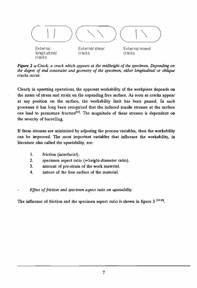
( I } )( ~~ )( \~ )External External shear External mixedlongitudinal cracks crackscracks
Figure 2 a-Crack, a crack which appears at the midheight of the specimen. Depending onthe degree of end constraint and geometry of the specimen, either longitudinal or obliquecracks occur.
Clearly in" upsetting operations, the apparent workability of the workpiece depends onthe states of stress and strain on the expanding free surface. As soon as cracks appear
at any position on the surface, the workability limit has been passed. In suchprocesses it has long been recognized that the induced tensile stresses at the surfacecan lead to premature fracture[141. The magnitude of these stresses is dependent onthe severity of barrelling.
If these stresses are minimized by adjusting the process variables, then the workabilitycan be improved. The most important variables that influence the workability, inliterature also called the upsetability, are:
1. friction (interfacial).
2. specimen aspect ratio (=height-diameter ratio).3. amount of pre-strain of the work material.4. nature of the free surface of the material.
Effect of friction and specimen aspect ratio on upsetability
The influence of friction and the specimen aspect ratio is shown in figure 3 [1S-25I.
7
~ I-tt~h~. err;..
I-ttQI], ICliaExternal shear eras.o f)~cracks eCl r
aliaExternal mixedcracks
Externallongitudinalcracks
CDW
c(\jL+-'(f)
0...ooI
a
AXial strain E: z
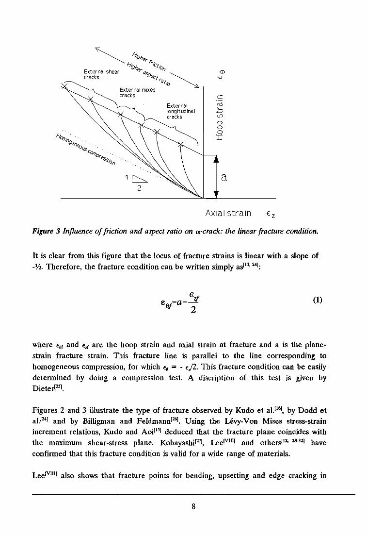
Figure 3 Influence offriction and aspect ratio on ex-crack: the linear fracture condition.
It is clear from this figure that the locus of fracture strains is linear with a slope of-Vz. Therefore, the fracture condition can be written simply asl13, 241:
€e =a--!l
6j 2(1)
where €ef and €zf are the hoop strain and axial strain at fracture and a is the planestrain fracture strain. This fracture line is parallel to the line corresponding to
homogeneous compression, for which €e = - €j2. This fracture condition can be easily
determined by doing a compression test. A discription of this test is given byDieterl25l.
Figures 2 and 3 illustrate the type of fracture observed by Kudo et al.1161, by Dodd etal.1241 and by Billigman and Feldmannl26l . Using the Levy-Von Mises stress-strainincrement relations, Kudo and Aoil151 deduced that the fracture plane coincides withthe maximum shear-stress plane. KobayashiI27J, LeeJVllll and othersll2, 28-
321 have
confirmed that this fracture condition is valid for a wide range of materials.
LeeJVlIl] also shows that fracture points for bending, upsetting and edge cracking in
8
rolling, all fall on the same straight line for a given material. Therefore the linear
fracture condition is not confined to upsetting but is of wider generality.
Effect ofpre-strain on upsetability
It is well-known that the ductility of a material is strain-history dependent(33). This hasbeen confirmed in papers by Billigman[341, by Gill and Baldwinn[35] and by Luntz[361,
who have shown that wire drawing after annealing can in some cases increase theworkability in subsequent upsetting operations. Similar results were obtained byTozawa and Kojima[37).
Effect of surface defects on upsetability
In industrial upsetting and heading operations on wire and rod, the workability limitis often determined by the presence of longitudinal surface defects, such as grooves,scratches or cracks. These defects may originate from the ingot or, more often, fromprior forming processes such as wire drawing[26I. In upsetting, such defects act as
circumferential stress concentrators and they limit the workability of the material.Thomasonl12J obtained similar results. He found that the greater the aspect ratio ofthe cylinder, the lower the effect of surface defects. It was also found that theupsetability decreased with increasing defect depth, and that variations in the defectroot radius only had a secondary effect.
Prevention of a-cracks
The linear fracture condition for a-cracking in upsetting and related processes can beseen as a guide to the workability limit of a material. In the development of a newpart, care should be taken to remain within the range of permissible surface strains ofa particular material. For crack-free upsetting of the material, the surface strain pathsshould always fall below the fracture line (see figure 3). In the forming of a newshape the surface strains should be determined. If the strain paths crosses thefracture line before the process is completed, fracture will occur. To avoid this, eithera material with a higher "a-value" should be chosen, or the process variables shouldbe altered. For example, if fracture is found to occur, the use of good lubrication willdecrease the slope of the strain path and possibly avoid fracture. Kuhn et al. [38-40)show that this approach is a useful one. Kuhn[4lJ also finds that this condition is validfor other forming processes than upsetting and open-die forging e.g. bending. The
9
other factors that influence the workability, cannot be forgotten. Although prevention
of an a-crack by an extra annealing and subsequent drawing step or the examining ofall the incoming material will always lead to extra costs, these actions can be just aseffective.
2.3.2 p-crack
(j-Cracks (see figure 4) are defined as longitudinal cracks which occur at the bottom
of the inner part of the specimen in upsetting with a truncated conical punch. This
type of crack is caused by the expansion of material under the cone punch in circumferential direction.
Inter'nallongitudinalcracks
Figure 4 {j-Crack, a crack which occurs at the bottom of the inner part of the specimenin upsetting with a truncated conical punch.
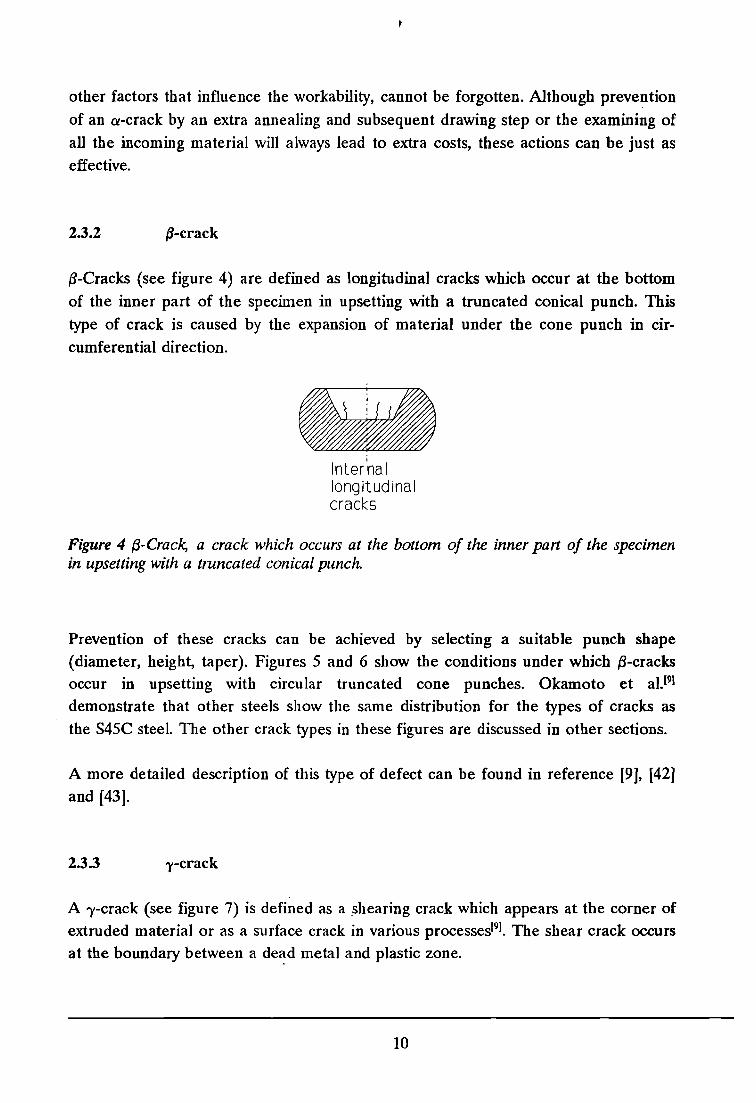
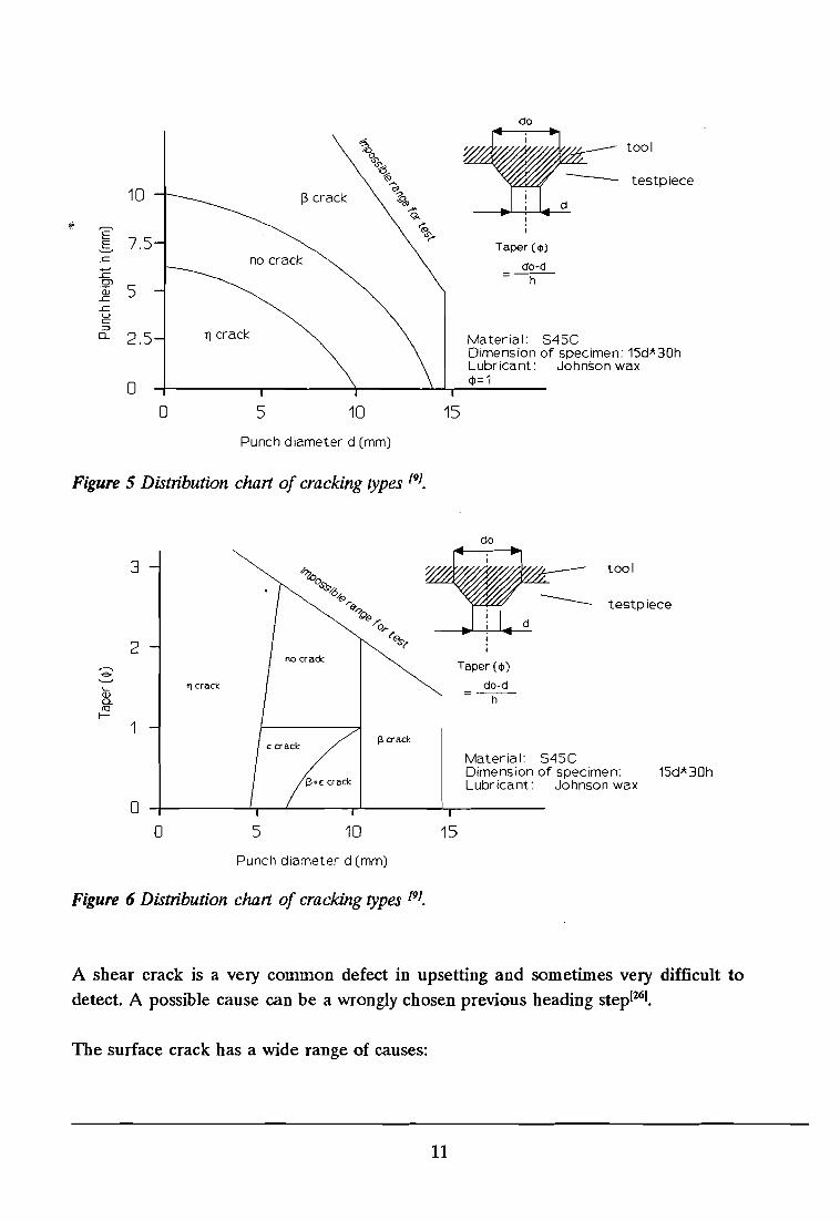
Prevention of these cracks can be achieved by selecting a suitable punch shape(diameter, height, taper). Figures 5 and 6 show the conditions under which {j-cracksoccur in upsetting with circular truncated cone punches. Okamoto et aI.(9(demonstrate that other steels show the same distribution for the types of cracks as
the S45C steel. The other crack types in these figures are discussed in other sections.
A more detailed description of this type of defect can be found in reference [9], [42]and [43].
2.3.3 -y-crack
A ')'-crack (see figure 7) is defined as a .shearing crack which appears at the corner ofextruded material or as a surface crack in various processes[9J• The shear crack occursat the boundary between a de~d metal and plastic zone.
10
do
"?l tool%%~ testpiece
10 13 crack ~~....
q...~~.
E ~
7.5u;..
E Taper (<Ill.........c no crack......, do-d.c =-h-0>'(i) 5.c.cvc:::>
11 crack0.. 2.5 Material: S45CDimension of specimen: 15d*30hLubricant: Johnson wax
0 <!l=1
0 5 10 15
Punch diameter d (mm)
Figure 5 Distribution chart of cracking types [91,
do
Material: S45CDimension of specimen: 15d*30hLubricant: Johnson wax
3
2
----€o-........'1 craCK
OJCl.<0f-
1
oo 5 10
13 craCK
Taper (q,)
do-dh
15
--- tool
testpiece
Punch diameter d (mm)
Figure 6 Distribution chart of cracking types [91,
A shear crack is a very common defect in upsetting and sometimes very difficult todetect. A possible cause can be a wrongly chosen previous heading step[261,
The surface crack has a wide range of causes:
11

Sheal clacks SUlface clacks
Figure 7 -y·Crack, a crack which appears at the comers of extruded material in freeextrusion. Cracking occurs at the boundary between dead metal and plastic zone.
-y-cracks, shear cracks, that occur at the corner[9]stresses induced by finishing processes[26]skin inclusions or non-metallic parts[26]previous process steps[261
lubrication explosion[26]expansion of the slug surface[42]feed marks that are produced when the slugs were machined[42].
These cracks can be prevented by selecting suitable die and workpiece dimensionsand by a careful workpiece preparation. Figure 8 shows results from tests done byOkamoto et al.[91. They conclude that no cracking occurs when the ratio of the initialdiameter of the specimen, Do, to that of the die cavity, d, is kept below 2. The othercrack type in this figure is discussed in and other section.
12
3'1+8 crack
..c: 2 no crackI
'" crack
1Material: S45CDimension of specimen: 15d*30hLubricant: Johnson wax
0
0 1 2 3
Oo/d
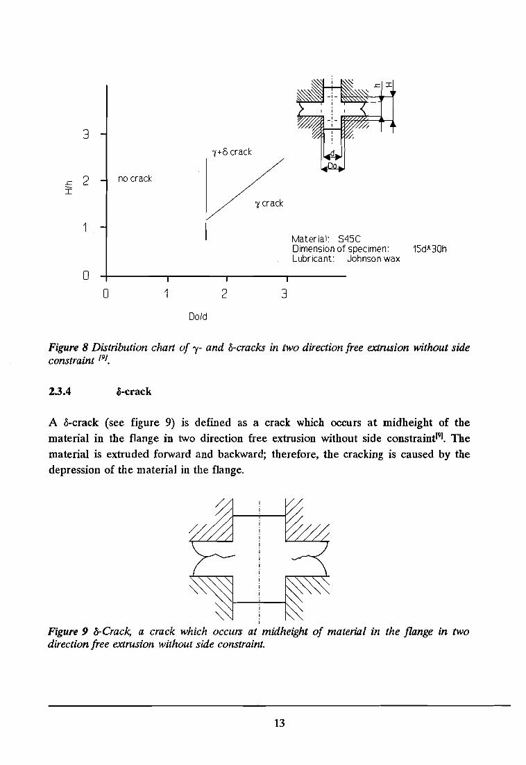
Figure 8 Distribution chan of "1- and o-cracks in two direction free extrusion without sideconstraint [91.
2.3.4 li-crack
A o-crack (see figure 9) is defined as a crack which occurs at midheight of the
material in the flange in two direction free extrusion without side constraintl9J• The
material is extruded forward and backward; therefore, the cracking is caused by the
depression of the material in the flange.
IiI
Figure 9 o-Crack, a crack which occurs at midheight of material in the flange in twodirection free extrusion without side constraint.
13
A prevention measure is to select a suitable diameter of the dies. Okamoto et aI.!9)
conclude from the chart in figure 8 that the ratio of the initial diameter of thespecimen, Do, to that of the die cavity, d, has to be kept below 2.
This type of crack occurs according to Okamoto et aI.[91 only in two direction free
extrusion. A more detailed description of this defect can be found in references [9]
and [45].
2.3.5 e-crack
An e-crack (see figure 10) is defined as a crack that occurs at midheight or just abovethe bottom radius of the inside surface and advances in the circumferential directionin upsetting[91.
Internaltransverse cracks
Figure 10 e-Crack, a crack which occurs at the midheight of the inside surface andadvances in the circumferential direction.
Causes for e-cracks are the punch shape[91, and the rapid change of the velocity fieldin the corners of a backward extruded product[441• The change of the velocity induces
a high strain at the corners. This phenomenon is observed mainly if the wall thicknessof the cup is relatively large in respect to the punch diameter.
Prevention of this type of cracks can be achieved by:
an annealing operation[44)forward instead of backward extrusion[44)tapered slugs in the case of forward extrusion(44)
an as high as possible hydrostatic pressure[441
changing the punch shape[91• From the chart lD figure 6 can beconcluded that in case of S45C steel e-cracks occur when the taper, 4>,of the punch is smaller than 1 and the punch diameter is between 5 and
14
10 mm. Okamoto et al.[9] also conclude that in general e-cracking is
observed between 1'/ and {3 ranges in case of a small punch taper « 1).
2.3.6 r-crack
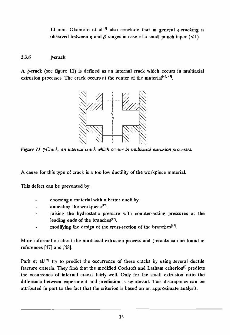
A r-crack (see figure 11) is defined as an internal crack which occurs in multiaxialextrusion processes. The crack occurs at the center of the material[46. 47].
Figure 11 r-Crack, an internal crack which occurs in multiaxial extrusion processes.
A cause for this type of crack is a too low ductility of the workpiece material.
This defect can be prevented by:
choosing a material with a better ductility.annealing the workpiece[47J•
raising the hydrostatic pressure with counter-acting pressures at theleading ends of the branches[47].
modifying the design of the cross-section of the branches[471.
More information about the multiaxial extrusion process and r-cracks can be found inreferences [47] and [48].
Park et al.[46) try to predict the occurrence of these cracks by using several ductilefracture criteria. They find that the modified Cockroft and Latham criterionII] predictsthe occurrence of internal cracks fairly well. Only for the small extrusion ratio thedifference between experiment and prediction is significant. This discrepancy can beattributed in part to the fact that the criterion is based on an approximate analysis.
15
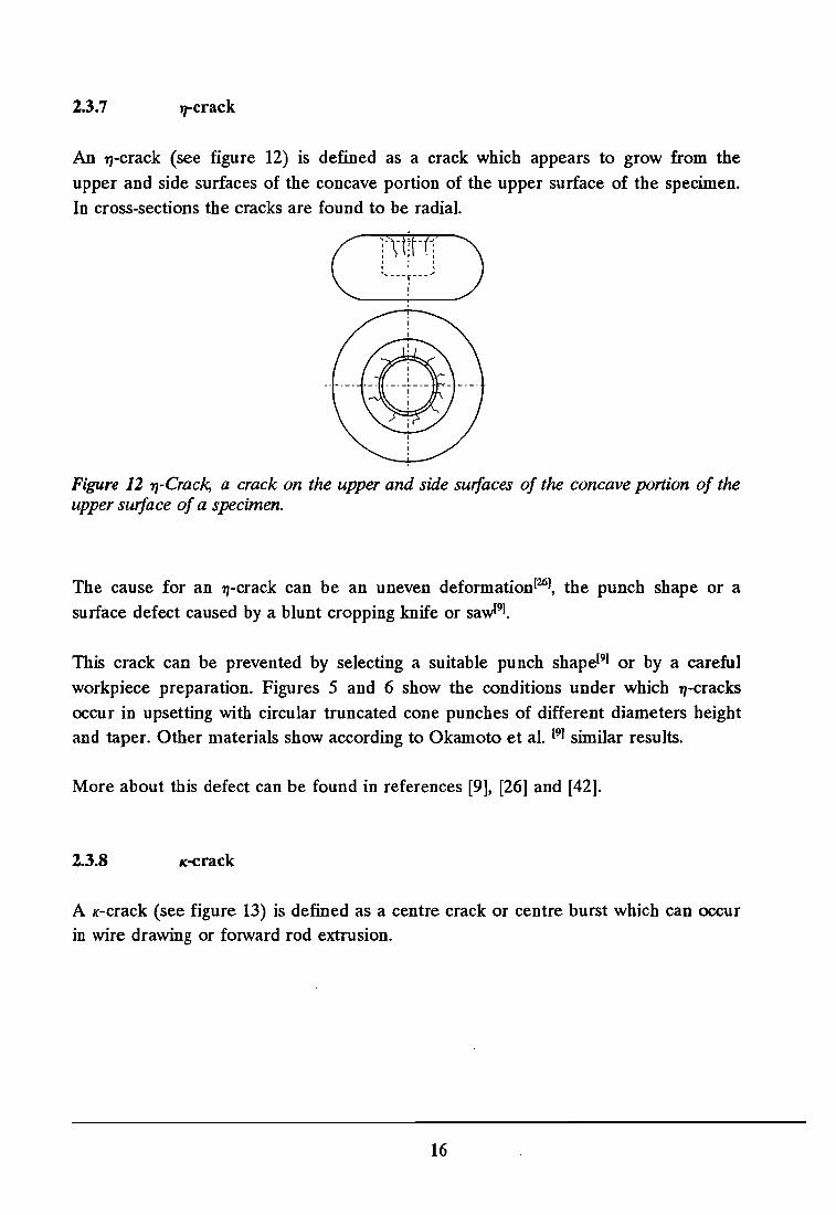
2.3.7 J1"'crack
An l1-crack (see figure 12) is defined as a crack which appears to grow from the
upper and side surfaces of the concave portion of the upper surface of the specimen.
In cross-sections the cracks are found to be radial.
Figure 12 'f'J-Crack, a crack on the upper and side surfaces of the concave portion of theupper surface of a specimen.
The cause for an 71-crack can be an uneven deformation(26), the punch shape or a
surface defect caused by a blunt cropping knife or sawl91.
This crack can be prevented by selecting a suitable punch shape(9) or by a careful
workpiece preparation. Figures 5 and 6 show the conditions under which 'f'J-cracks
occur in upsetting with circular truncated cone punches of different diameters heightand taper. Other materials show according to Okamoto et al. (9) similar results.
More about this defect can be found in references [9], [26] and [42].
2.3.8 ,,-crack
A K-crack (see figure 13) is defined as a centre crack or centre burst which can occurin wire drawing or fOIWard rod extrusion.
16
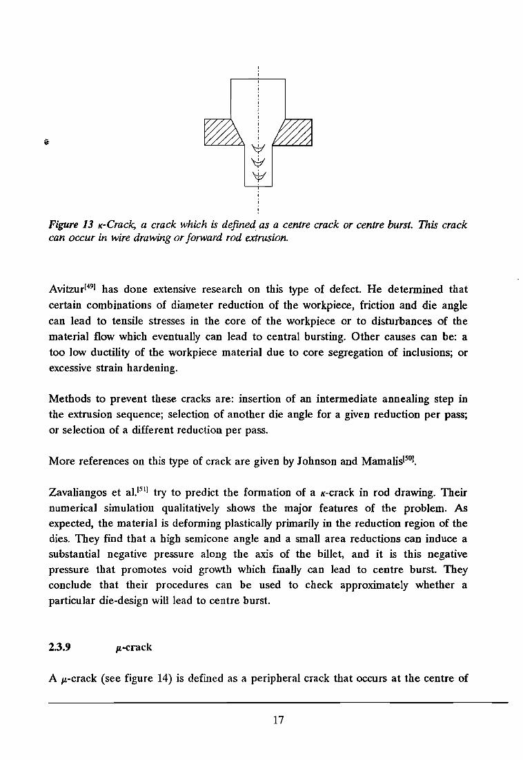
Figure 13 ,,-Crack, a crack which is defined as a centre crack or centre burst. This crackcan occur in wire drawing or forward rod extrusion.
Avitzur[49] has done extensive research on this type of defect. He determined that
certain combinations of diameter reduction of the workpiece, friction and die anglecan lead to tensile stresses in the core of the workpiece or to disturbances of thematerial flow which eventually can lead to central bursting. Other causes can be: atoo low ductility of the workpiece material due to core segregation of inclusions; orexcessive strain hardening.
Methods to prevent these cracks are: insertion of an intermediate annealing step inthe extrusion sequence; selection of another die angle for a given reduction per pass;or selection of a different reduction per pass.
More references on this type of crack are given by Johnson and Mamalis[SoJ.
Zavaliangos et al.[Slj try to predict the formation of a ,,-crack in rod drawing. Their
numerical simulation qualitatively shows the major features of the problem. Asexpected, the material is deforming plastically primarily in the reduction region of thedies. They find that a high semicone angle and a small area reductions can induce asubstantial negative pressure along the axis of the billet, and it is this negativepressure that promotes void growth which finally can lead to centre burst. Theyconclude that their procedures can be used to check approximately whether aparticular die-design will lead to centre burst.
2.3.9 Wcrack
A J,L-crack (see figure 14) is defined as a peripheral crack that occurs at the centre of
17
a specimen in combined fOlward and backward piercing.
Figure 14 wCrack, a crack that occurs at the centre of a specimen in combined forwardand backward piercing.
Okamoto et al.[9] are the only ones that mention this crack. They give one reference
in their paper.
2.3.10 A-crack
A A-crack (see figure 15) is defined as a crack which occurs at the bottom of theinner surface in piercing.
Figure 15 A-Crack, a crack that is caused by a too small punch radius in piercing.
The cause for this crack is a too small punch radius. This crack can be prevented byusing a larger punch radius.
Okamoto et aJ.l9] are the only ones that mention this crack.
18

2.3.11 O-crack
A 8-crack (see figure 16) is defined as a microscopic crack which occurs at theboundary between the upper and lower dead metal zones and at a point where themetal flow changes during excessive plastic deformation in in upsetting.
Figure 16 8-Crack, a crack which occurs at the boundary between the upper and lowerdead metal zones in upsetting.
Causes of this type of defect are:
a too low ductility of the material[26. SOl.
buckling in a previous process step[26I.
Some methods to prevent this type of defect are:
annealing of the workpiece.preventing of buckling in a previous step.
More references about this crack are given by Johnson and Mamalis[Sol.
2.4 Surface imperfections
Not much interest is being displayed in literature about surface imperfections such asroughening, scratching and laminations. These defects are most times fairly easy toovercome by improving the lubrication. But the choice of the lubricant still is notquite well understood. The tribological system variables and their influences inforging processes have not been researched extensively yet, so that the choice of a
lubricant and the kind of surface preparation still is a matter of experience.
19
Friction and wear (defects) may be explained through several related mechanisms:tearing of weldments, plowing, a thin surface layer of severe plastic deformations andgalling. While these mechanisms can provide a fundamental understanding of thephenomena of friction and of wear, the total picture is much more complicated.Other factors like corrosion, fatigue, erosion, cavitation, and thermal effects, can alsocontribute.
In the following sections the surface defects that were found in literature will beexplained. Only other ways to prevent these defects than improving the lubricationwill be mentioned.
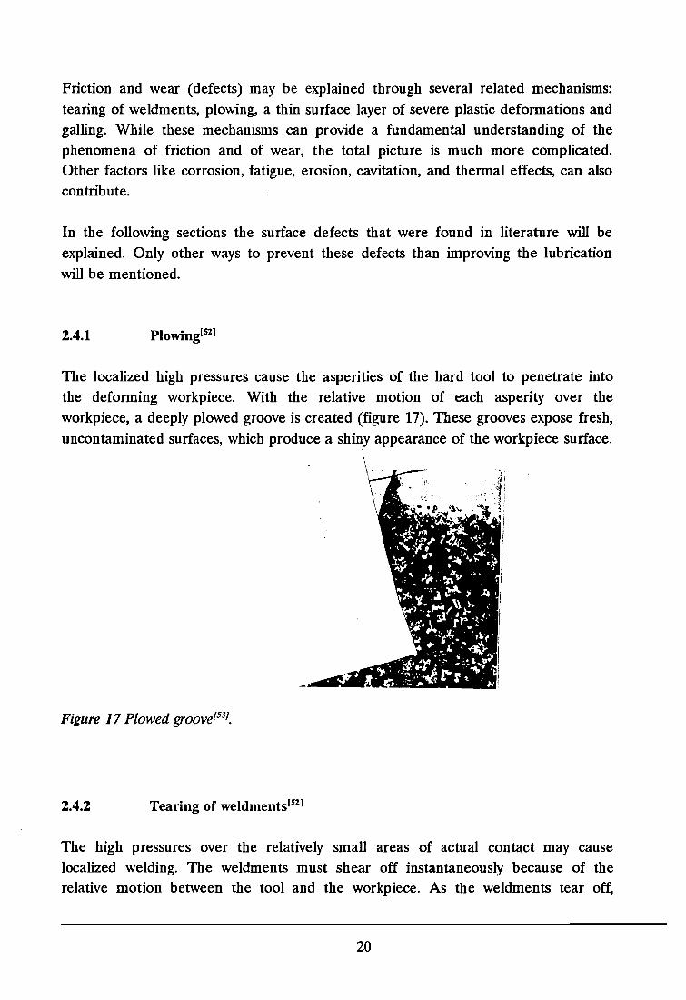
2.4.1 Plowingl521
The localized high pressures cause the asperities of the hard tool to penetrate intothe deforming workpiece. With the relative motion of each asperity over theworkpiece, a deeply plowed groove is created (figure 17). These grooves expose fresh,uncontaminated surfaces, which produce a shiny appearance of the workpiece surface.
Figure 17 Plowed groovel53J•
2.4.2 Tearing of weldments l521
The high pressures over the relatively small areas of actual contact may causelocalized welding. The weldments must shear off instantaneously because of therelative motion between the tool and the workpiece. As the weldments tear off,
20

localized high temperatures are created. The metals at the weld interface may formhard intermetallic compounds. As the weldments break loose, they cause damage toboth tool and workpiece. Intermetallic fragmented particles may now move betweenthe two mating surfaces and cause further damage. The particles may be pressed intothe workpiece, become imbedded, and present hard cutting edges plowing into thehard die. Thus, the die wears and roughens.
2.4.3 Galling[S21
When there is a strong chemical affinity between the tool material and the workpiece,layers of the workpiece material adhere to the tool surface and may becomeimmobilized. The difference between tearing of weldments and galling is that thegalling material contains only workpiece material, whereas the torn of weldmentscontain tool material as well.
2.4.4 Surface layer of severe plastic flOWIS2]
The description of plowing and tearing of weldments demonstrates tIlat a thin layer inthe surface of the workpiece is severely affected by friction between tool andworkpiece. The amount of deformation is highest at the interface; and diminishesfurther from the surface. Within a very thin layer, one order of magnitude higherthan the surface roughness, the deformation changes from severe on the surface toalmost zero below it.
2.4.5 Surface roughening due to coarse grain size
The grain size is, as Dautzenberg and Kals[54) state, one of the main causes for surface
roughening. For example when forging billets containing coarse grains are forged inclosed dies, the wrinkles often fold in to cause a series of small laps. Although theyare seldomly very deep, these laps produce a poor surface appearance that oftennecessitates considerable grinding and restrike forging. These wrinkles are commonlyknown as orange peel.
In agreement with the plasticity theory it can be assumed that the deformation takesplace by shear in the planes of maximum shear stress. From a metallurgical point ofview, this means that the nearest closed packed planes provide for shear by means ofdislocation glide. In the Taylor theory these planes are chosen on the basis of an
21
energy criterion. Inside the material this is necessary in order to maintain the
continuity of the material. This condition is absent for the surface grains. Especiallyfor material with a coarse grain size this can lead to extreme surface roughening
during the deformation of the workpiece. KudolS31 illustrates the effect of the grainsize of the workpiece material on the rate of roughening of the free surface of aworkpiece due to deformation.
Excessive lubrication of the tool-workpiece interface is another reason for surfaceroughening of the productIS3]. The lubricant prevents the tool surface from making the
workpiece surface smooth and, consequently, induces deterioration of the product's
surface finish.
Extreme roughening can be overcome by choosing a workpiece material with a small
grain size or a careful heat treatment of the billet, preform or interstage in order torefine the structure.
2.4.6 Remarks on surface imperfections and workpiece lubrication
Surface defects will become more important, especially in small quantity productionand near net shape forging. In these techniques material waste and machiningoperations are to be kept at a minimum.
More about friction, surface treatment and some general guidelines concerninglubrication can be found in several handbooks, e.g. the handbooks by AvitzurlDlI or byLange(VII. The ICFG has also published a report about lubrication aspects in coldforging [XI1.
MayrhoferlSS1 discusses the obtainable surface roughness and the process variablesthat affect this roughness for some extrusion processes.
More specific problems are discussed in journals such as Wear and TribologyTransactions.
2.5 Flow imperfections
The flow imperfections represent a wide range of defects, including such defects asbuckling, non-concentricity, folding and the occurrence of fins and flashes.
22
Flow imperfections will be one of the most important defects in near. net shapeforging processes since in these processes as accurate as possible products and nomaterial waste, subsequent machining or trimming are wanted.
Three kinds of flow imperfections can be distinguished[56]:
1. dimensional inaccuracies: the inability to achieve the designed dimensions.
2. shape inaccuracies: the inability to meet the designed product shape.3. positional error: the inability to align the several design features.
The factors and sources that result in these three kinds of flow imprecisions are listedby Kudo[53} as:
1. heredity of bar quality (material stock).2. heredity of billet quality (billet preparation).3. improper lubrication.4. poor precision, rigidity, strength and wear-resistance and thermal
distortion of forming tools.5. poor preci~ion rigidity and wear-resistance of the forming machine.6. undesirable deformation of workpiece due to improper product, process
and tool design.7. imprecision generated during and after ejection of the workpiece.8. insufficient operational control resulting from improper planning,
facilities and operator.
Mayrhofer[55l, Leykamml56] and Lange[57] use similar lists in their work.
In the following sections these factors will be briefly discussed.
2.S.1 Material stock
Heredity of the qualities of material stock and billet play an important role indetermining product qualities in metal-forming processes[57. 581. This is especially the
case in net-shape fonning in which preservation of the original surface is aimed for.
The mechanical properties of the material stock, i.e., bar, wire or plate aredetermined by their chemical composition and previous thermal and mechanicaltreatmentl53. 55, 57, 581. When there is scatter in the the work-hardening characteristic of
23
the workpiece material the products will have dispersing thicknesses and otherdimensions caused by fluctuation of the forming load and springback. Consequently,the deflections of the tool and machine will differ from one workpiece to another.
KudolS3) gives some examples of the influence of the bar quality on the dimensional
accuracy that can be achieved by a forging process.
Defects due to inadequate bar quality can be prevented by: a careful heat treatmentof the billet, preform or interstage, favourable lubricant conditions and more rigidtooling.
2.5.2 Billet preparation
Billets are prepared by a separation process from bar, wire, plate or tube stocks. Thevolume is the property of the billet or blank that is transmitted to the product. Inbulk-forming processes, over-volume billets may result in extra flashing and excessivetool and press load, while under-volume billets lead to incomplete products.
The inaccuracies in the preform or interstage, which subsequently lead to volumefluctuations, are a result of variations in the cross sections of the stock material.These variations are allowed to be according to DIN 1541 up to 16% and accordingto DIN 1013 about 5%. In addition, variations in the parted-off lengths, caused by theprocess, also affect the volume accuracy. The fluctuation in billet length when thebillet is being sawed is 2 to 4% and in case of the billet being cropped 4 to 8%(5
5).
The excess volume of the material must be machined from the workpiece.
KudolS3] gives some examples of dimensional inaccuracies that are caused by
imprecisenesses of the billet.
Defects that can be caused by billet irregularities are amongst others: buckling, foldsand burs, flashes and incomplete products.
2.5.3 Lubrication
High coefficients of friction due to poor lubrication generally cause non-uniformdeformations, such as surface barrelling in upsetting and additional shear strains inextrusion and rolling, which lead to non-homogeneous properties within the materialand, in some cases, to surface or interior cracking (see 2.3.1). Poor lubrication also
24
induces high forming loads, workpiece-tool adhesion and tool wear. The high formingload and the tool wear directly influence the product dimensions.
Poor lubrication causes fluctuation in the coefficient of friction, which brings aboutvariations in the shape dimensions, surface roughness (see chapter 2.4) and fractureof the products. A good example of the influence of imperfections in the lubricationon the material flow is given by Ramaekers and KalsIS9). In their paper instablematerial flow in an upsetting operation is connected with imperfections in thelubrication.
A too thick lubricant layer at the workpiece-tool interface, effects the surface finishof the product (see 2.4.6). Excessive lubricant deposited or trapped in tool recesses orfillet corners often prevents the material from completely filling the tool cavity. Thisdefect can be prevented by designing lubricant drains in the die.
2.5.4 Tools
The accuracy of tools is very important for the accuracy of the products: forming is ina way copying. The tool can be considered an analog storage for dimensions andshape. Deviations from the desired values in the tools show up as systematic errors inthe workpiece.
Factors that induce dimensional inaccuracies in the workpiece are:
elastic distortion of the tool componentslS3. 57.58).
This effect can be decreased by using tool components with a highYoung's modulus, e.g. tungsten carbide. Rigid tooling has a higherspring constant, with smaller elastic deformations, for a given loadingcondition. Kudo(53) gives an example of the influence of the insert'smaterial on the distortion of a tool.temperature distortion of the tool componentsIS3). Changes in tooldimensions due to a steady temperature rise cannot be avoided. Withthe use of controls and regulations, a computer aided correction, e.g.software correction, in the closing area of the tool is practicable. Aprototype of such a system has been realized at IFUM in HannoverIS9).wear of the tool componentslS3, 57,58). In production the dimensions of
the tool change because of wear and deformation. If sliding cannot beavoided, the wear can be reduced by using wear-resistant tools andgood lubrication. When the wear behaviour under production conditions
25

is known, techniques such as statistical process control and samplecontrol can be used[57. 58).
Kudo(53) and Lange[57. 58) give various examples of the effects of the tool precision on
the final dimensions and shape of the workpiece. In general, dimensional and shapedefects can be prevented by: a high tool accuracy and small dimensional changesduring manufacturing through wear.
2.5.5 Forming machine
A considerable amount of distortion takes place in the press construction and indriving elements that are subjected to the working load and torque. Lange[57. 58)
distinguishes three factors that affect the production accuracy:
1. ram or hammer guidances.2. stiffness behaviour of the machines.3. fluctuations in the work capacity of the machines.
Since the forming tool is generally made of two parts, a proper guidance of the ramin the frame is important for good positional accuracy. The positional error of a tool
is the sum of the positional error during contact (without load) and the positional
error due to drifting (under central and eccentric loading). The latter results in ramtilt. Ram tilt can lead to such defects as buclding[611 and fracture of the workpiece.
Special interest has been displayed in the layout of adjustable guide forms ofmetalworking machines and of the resulting flux of force[60I. Doege(60) gives someexamples of, and alternatives to the in industry used layout of guides.
The stiffness behaviour of the machines is influenced by several elements of themachines used: guidance of the ram, cross-head, press drive and frame, forexample(60
). In general, the elastic deflections will be smaller in a more rigid press. Itis therefore necessary to use more rigid presses such as die forging and coiningpresses, in order to obtain close dimensional tolerances on thickness in the forcedirection. Closed-frame presses are to be preferred to C-frame presses for suchprocesses [53.57).
Fluctuations in the work capacity affect the thickness of the product. The availablework capacity should therefore be maintained constant for increased requirements on
26
accuracy. LangelS7] gives some examples of how this should be done: the use of relays
in the control of drop hammers, and the control of the screw speed in the case of
screw presses.
2.5.6 Process and tool design
When the product, process or tool design is inadequate, extremely high working loadsmay be required to attain satisfactory filling of the tool cavity. This may causedistortion or failure of the tool or machine.
KudolS3) gives three examples of dimensional inaccuracies that are caused by improperprocess design.
2.5.7 Product handling
Imprecision of the product generated during and after ejection can have manyreasons, for example:
improper ejection of the formed product.elastic shrinkage of a die having no draft angle.
shrinkage of the product due to cooling.
An improper ejection method may distort the product shapeIS3). The ejection methodshould therefore be carefully chosen.
The elastic shrinkage of a die having no draft angle can cause a slight plasticdeformation of the product. This is easily overcome by designing a die with a slightdraft angle. In this way a product is pushed out of the die by the elastic shrinkage.
Although shrinkage of the product due to cooling after (hot) forming is said to be areason for product inaccuraciesIS3), for example in fast cold extrusion, LeykammlSS)
states that a temperature rise of the workpiece does not influence the accuracy of theproduct. Leykamm explains this by saying that an expansion of the die due to thetemperature rise of the workpiece compensates the expansion of the workpiece.Dimensional inaccuracies can, according to KudoIS3), be overcome by adjusting thedie, e.g. by designing a die which is slightly oversized.
27
2.5.8 Operational control
For the reasons stated in the preceding sections, imprecision in formed parts resultsfrom changes or fluctuations in the current workpiece temperature due to nonuniform heating in the furnace, varying cycle time due to manual operation, etc.Omission of occasional scouring to remove pick-up from tool surfaces or ofcontrolling deterioration and concentration of lubricant may cause changes in theoperational conditions and, consequently, changes in the quality of the product.
28
3 Defect avoidance
In the previous chapter the emphasis was on defects, their causes and the ways to
prevent them. These are the basic things that are needed for the avoidance of defects.
fIn literature several manners to avoid defects in products are mentioned:
statistical process control (SPC)physical modellingmathematical modelling (FEM, UBET)databaseknowledge based system, expert systemneural network
In the following sections the techniques involved and a knowledge based system
which was proposed by the author will be discussed.
3.1 Statistical process control
Statistical process control is in cold forging used to avoid dimensional and shapeinaccuracies. In view of the fact that cold forging processes are still primarily used forthe mass production of components, statistical process control has becomeengineering standard practice in the effort to assure production quality. Here, theword "control" means closed loop control. During production, a check is kept on theway certain quality determinant parameters are changing. This enables correctiveaction to be taken while parts are still being produced within tolerance limits.
SPC requires information on(62, 631:
1. systematic errors: errors caused by such factors as tool wear, elastic andthermal deformation.
2. random errors: errors caused by uncontrolled factors.3. quality of the production process: tolerances that can be achieved with
a certain process (process capability) and specific machine (machinecapability).
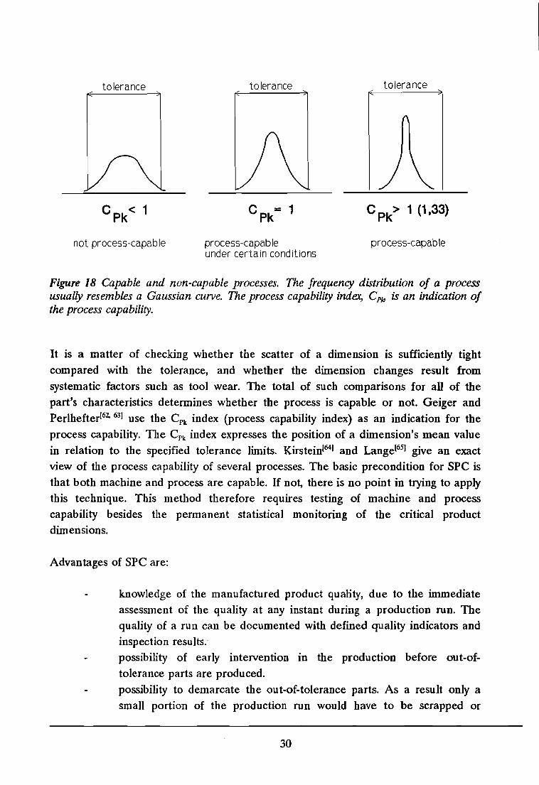
Figure 18 shows what is meant by capable and non-capable processes. In words: theprocess capability is the process quality in relation to the tolerance described for apart.
29
tolerance
C pk< 1
not process-capable
tolerance
process-capab Ieunder certain conditions
tolerance
C Pk> 1 (1.33)
process-capab Ie
Figure 18 Capable and non-capable processes. The frequency distribution of a processusually resembles a Gaussian curve. The process capability index, Cp~ is an indication ofthe process capability.
It is a matter of checking whether the scatter of a dimension is sufficiently tight
compared with the tolerance, and whether the dimension changes result from
systematic factors such as tool wear. The total of such comparisons for all of the
part's characteristics determines whether the process is capable or not. Geiger and
Perlhefterl62, 63) use the CPk index (process capability index) as an indication for the
process capability. TIle Cpk index expresses the position of a dimension's mean value
in relation to the specified tolerance limits. Kirsteinl641 and Langel6S) give an exact
view of the process capability of several processes. The basic precondition for SPC is
that both machine and process are capable. If not, there is no point in trying to applythis technique. This method therefore requires testing of machine and process
capability besides the permanent statistical monitoring of the critical productdimensions.
Advantages of SPC are:
knowledge of the manufactured product quality, due to the immediate
assessment of the quality at any instant during a production run. Thequality of a run can be documented with defined quality indicators and
inspection results.possibility of early intervention in the production before out-of
tolerance parts are produced.
possibility to demarcate the out-of-tolerance parts. As a result only a
small portion of the production run would have to be scrapped or
30
subjected to 100% inspection.
An effect that according to Geiger and Perlhefter(63) should not be underestimated, is
the strengthening of employee interest in quality matters when SPC is introduced.This can lead to improved quality of the products.
Disadvantages of SPC are:
SPC cannot guarantee IIzero defectll Slllce it is based on random
sampling. The forthcoming standard deviation is only a calculated
estimation, which itself is subject to confidence limits. The SPCtechnique only tells how many products are likely to be defective.SPC cannot guarantee the detection of random defects in the order ofp.p.m, (parts per million), e.g. defects in the original blanks or swarf.Only 100% inspection can eliminate such defects, and, because of faultyinspection even this cannot guarantee a zero defect result.the size of random samples has to be chosen large enough as to
eliminate the influence of an individual measurement. Extreme figureswould otherwise throw off the results.
More details and examples are given by Geiger and Perlhefter in their papers onSpCI62, 63).
3.2 Physical modelli ng
Development work cannot be conducted with production equipment, since it willdisrupt the work done in the plant and will cause very high expenses. It is commonpractice to establish separate development laboratories with highly instrumentedequipment. In this way it is possible to record all the data needed withoutinterruption of the production process.
Because the use of production-scale equipment is expensive, normally all the tests arescaled down. Scaling down is a straightforward process when the workpiece isdeformed at room temperature, and film lubrication and heat transfer are not factorsthat must be consideredl661•
Flow patterns, including defect formation and forming forces can be studied on asmall-scale workpiece with smaller dies, smaller equipment, and smaller forces.
31
Another simulation technique, the model material technique, has been developed byWanheim et al.[67-7ol. This technique uses model materials like wax, lead or plasticine
to replace the workpiece material.
The model material technique is a 3-D technique and is very useful for determiningflow, geometry, thrust magnitudes, pressure distributions and the effects of friction.This makes the technique suitable for the prediction of a workability limit of amaterial in a forging process. A good example is given by Yoshida and Wanheiml681 intheir prediction of surface cracking.
3.3 Mathematical modelling
A reliable analytical model provides a determination of the dependent processparameters such as forces and flow patterns (fracture and failure) as functions of theindependent parameters. Process design can be achieved with a high degree ofsuccess, and trial and error with the actual production equipment or physical modelsis minimized. This makes that mathematical modelling is one of the least expensivemodelling techniques.
Due to the increasing capability and availability of computers, numerical simulationmethods such as the finite element method (FEM) and the upper bound elementaltechnique (UBET) have been developed to a sophisticated degree. These techniquesmake it possible to determine the influence of the process parameters, e.g.lubrication, tool geometry, punch speed.
As mentioned in the previous section, there are several modelling methods: slabmethod, upper bound method, finite element method, for example. In comparisonwith the experimental procedures like material modelling, it is noted that thedevelopment of a mathematical model is more time-consuming. Whereas itsometimes takes months to derive a mathematical criterion, the problem may besolved in days or weeks by a trial-and-error experimental procedure. With anexperimental solution though, only the solution of a specific case is obtained while ananalytical model can give a general solution.
A complete review of these techniques is quite impossible, since it would beincomplete or outdated. Many papers about numerical simulation of forging processescan be found in the Journal of Materials Processing TechnologylAI. There are severalother journalslB-F] though, in which a considerable part of their articles involvenumerical simulation techniques.
32
A good example of the application of a 2-D FEM programme for the simulation ofcold forging processes is given by Dh et aV71
]. Mielnikl72] gives a comprehensive
explanation of mathematical simulation of forging processes; the FEM is one of them.
3.4 Database
A database is a collection of data maintained by a database management system. Thedatabase management system is a file management system that assists in the
operations of entry and storage of data and in linking related records of different
types together.
JohnsonllO] and Al-Mousawi et al.192] emphasize the necessity for the design of a
database with data on defects. Such a database should, once completed, provide avaluable source of information for academic researchers and process engineers. Thedatabase has to be flexible and updated to include new information.
With a database it would be possible to anticipate or avoid defects in a product. It
would also be possible to couple such a database to an expert system as will beintroduced in section 3.5.
3.5 Expert system
Expert systems are computer programmes which model human expertise and applylogic (inference) to the knowledge base in solving problems. The knowledge baseitself is an organized set of information, i.e. a database, in the computer memory,obtained from people who are experts in a particular field, e.g. experts inmetalworking processesI73].
The benefits of an expert system are: reduced time to market, capturing of theengineering knowledge and the ability of concurrent engineering. All these benefitsare induced by the capturing of all the needed engineering knowledge into oneintegrated product model.
33
However, to make such a system operable for cold forging processes, highlyspecialized knowledge must be supplied in the following three areas(73):
1. Design for production. Very specific cold forging rules must be provided,relating to such aspects as dimensions, shapes, surface finish,mechanical properties, in order to determine whether or not coldforging might be used to produce the particular shape. Even just torealize that a component might be suitable for cold forging needsspecialist knowledge, which most product designers could not possibly
possess.
2. Process planning. An optimizing system must be provided to select thebest sequence of operations from those given, that will produce the partin the quantity desired at the lowest costs.
3. Production equipment centre layout. The proper selection, design anddevelopment and layout of the production equipment involving suchequipment as presses, tooling, annealing furnaces, lubrication systems,that are essential for successful operation.
These three engineering activities are closely related, as has been shown by Lange(74.75). A fully competent component design for cold forging cannot be evolved, unless
alternative process sequences and their effects on production equipment design, costsand the properties of the product are considered first.
As a result of the variety of cold forging processes, the products that can beproduced, the defects that can occur and the causes of the defects, the developmentof an expert system must be based on several classifications. Appropriate processingsequences, design rules, process conditions, etc. can only then be formulated for eachclass of part and/or processes when these classifications are made.
The answers that are wanted from a cold forging expert system are:
the forming stages.forming load (in each stage and total).requirements as to forging machine; i.e., maximum load, stroke.maximum strain and degree of work hardening in the final product andpreforms.dimensional accuracy of the product.shape and size of the starting workpiece.
34
requirements as to intermediate heat treatment and lubrication.
total costs, including tool costs.
Some of these answers can be derived out of already existing expert systems, but most
of these systems only give an answer to certain questions.
Expert systems have proven to be able to increase the consultation speed in the threementioned areas!73, 76-90) and to provide reliable results. Most of these systems have
been developed for process planning!73.76. 7S-861. More about expert systems can be
found in reference [6] or in the other given references.
3.5.1 Evaluation of defects and causes of defects
A classification of defects and their causes is not used in any expert system so far.
But such classifications may provide the possibility of solving numerous problems in
this field more efficiently, not only for the computation of the workability limit, but
also its optimization, the varying of some parameters, and so forth. These
classifications make it possible to answer questions about required intermediate heat
treatment and lubricatiop; answers that are not given by the existing expert systems.
When such an expert system has a design environment, it could adjust the product
design so as to prevent some of the defects from occurring.
A possible programme structure for an expert system which includes the evaluation of
defects is shown in figure 19. In this figure, i-I, i and i+ 1 correspond to stages in a
generalized multi-stage process.
A programme for computer-aided evaluation of the workability limit requiresdefinition of the following data:
1. Process.
2. Workpiece type.3. Workability limit.
4. Characteristics of the forming material for example, degree of prestrain
and mechanical properties.
5. Dimensional and geometrical characteristics of the initial shape of theworkpiece.
6. Dimensional and geometrical characteristics of the final shape of the
workpiece.7. Working conditions.
35
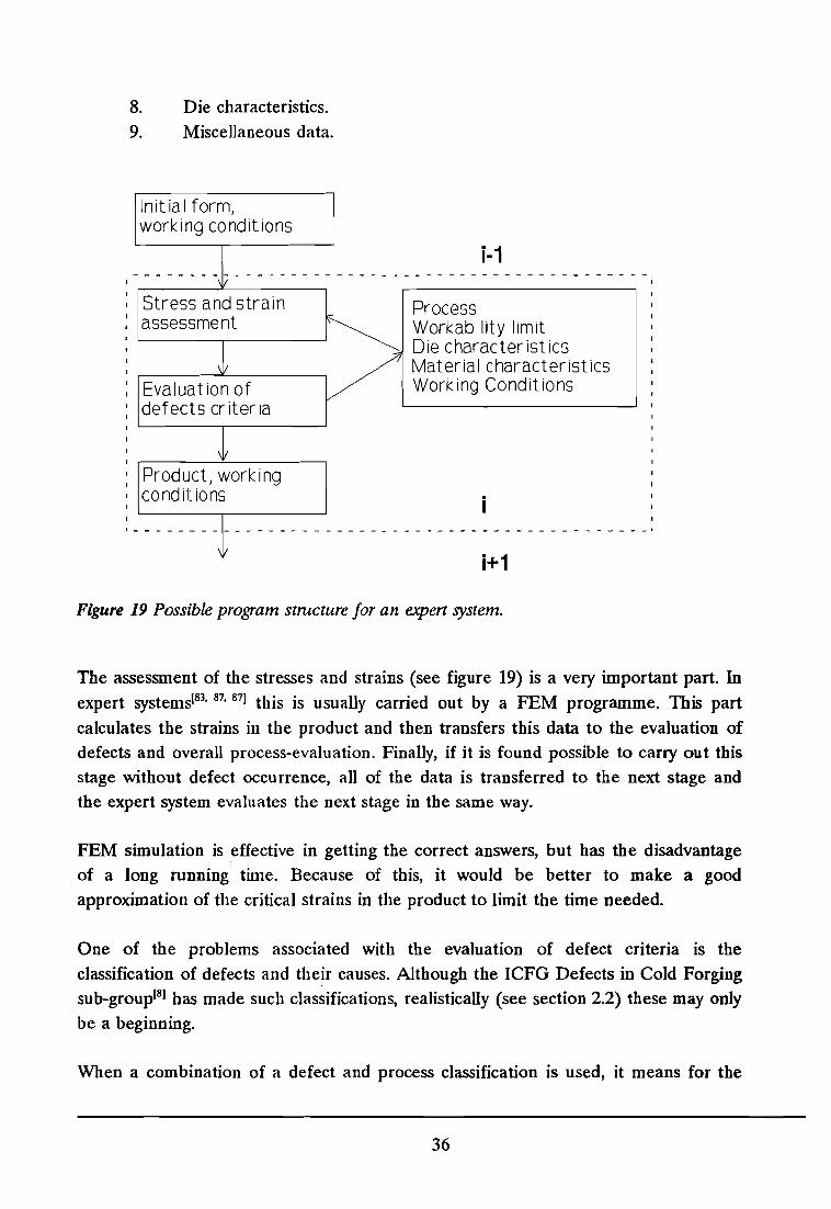
Stress and strainassessment
8. Die characteristics.9. Miscellaneous data.
Initial form,working conditions
i-1- - - - - - - - 1/ - - - - - - - - - - - - - - - - - - - - - - - - - - - - - - - - - - - -
~ Process~ Workabi lity limit
L-- ,.- --' ~ Die characteristics,.---__---"'-- ---,. / Material characteristicsEvaluation of V Working Conditionsdefects criteria
Product, work ingconditions
i+1
Figure 19 Possible program strncture for an expert system.
The assessment of the stresses and strains (see figure 19) is a very important part. Inexpert systems[83, 87,87] this is usually carried out by a FEM programme. This part
calculates the strains in the product and then transfers this data to the evaluation ofdefects and overall process-evaluation. Finally, if it is found possible to carry out thisstage without defect occurrence, all of the data is transferred to the next stage andthe expert system evaluates the next stage in the same way.
FEM simulation is effective in getting the correct answers, but has the disadvantageof a long running time. Because of this, it would be better to make a goodapproximation of the critical strains in the product to limit the time needed.
One of the problems associated with the evaluation of defect criteria IS theclassification of defects and their causes. Although the ICFG Defects in Cold Forgingsub-group[8] has made such classifications, realistically (see section 2.2) these may only
be a beginning.
When a combination of a defect and process classification is used, it means for the
36
expert system, that only rules related to a certain combination of defect and processhave to be consulted. This has two main advantages:
1. since the number of clauses the interpreter has to search through isdecreased, the execution time is decreased.
2. since the number of clauses in the knowledge base is decreased, thepossibility of conflicting rules is also decreased.
In figures 20-23, the global relations between the defect and its possible causes aregiven in terms of the classifications used by the ICFG Defects in Cold Forging subgroup. The major causes for a defect are highlighted.
Figure 20 Possible causes for fractureor cracking (DI). The main cause forthis defect is the tool properties (C3).
Figure 21 Possible causes for surfaceimperfections (D2). The main causefor this type of defects is the tribological variables (C4).
37
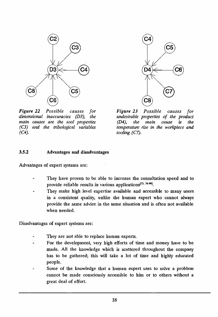
Figure 22 Possible causes for·dimensional inaccuracies (D3), themain causes are the tool properties(C3) and the tribological variables(C4).
3.5.2 Advantages and disadvantages
Advantages of expert systems are:
Figure 23 Possible causes forundesirable properties of the product(D4), the main cause is thetemperature rise in the workpiece andtooling (C7).
They have proven to be able to increase the consultation speed and toprovide reliable results in various applications[73.76-90I•
They make high level expertise available and accessible to many users
in a consistent quality, unlike the human expert who cannot always
provide the same advice in the same situation and is often not available
when needed.
Disadvantages of expert systems are:
They are not able to replace human experts.
For the development, very high efforts of time and money have to be
made. All the knowledge which is scattered throughout the company
has to be gathered; this will take a lot of time and highly educated
people.
Some of the knowledge that a human expert uses to solve a problem
cannot be made consciously accessible to him or to others without a
great deal of effort.
38
3.6
It is hard to predict the break-even point for knowledge-based systems.You cannot point exactly where the benefits will be. In this way it is
hard to convince managers of the need for these systems.Lack of software tools for implementing expert computer systemsl91J•
Neural networks
Neural networks can be seen as expert systems since they have the same functions.Besides, they add some human reasoning and decision making.
A good example of a neural network for cold forging is the one that has beendeveloped by Osakada et al.l91J• This neural network decides which process sequence
is the best one for a new product. This decision is being made after a training of the
neural network with example products of which the process sequences have alreadybeen determined. A problem which is caused by this need for training is theacquisition and selflearning of reliable knowledge. When this training has beensuccessful, most of the process sequences of new products can be correctlydetermined by the neural network.
39
4 Conclusions and remarks
1. There is a wide range of defects which occur during metal forming processes.
A method of dealing with these defects is of considerable interest, because lossof products due to defects will lead to extra costs, costs which will decrease thecompetitiveness of a manufacturer.
2. There is some confusion in literature in the use of various terms associatedwith defects and ductility. The term defect is by most people only related tofracture. However, when noticed that the term defect is only used in relationto the term workability and not in relation to ductility or formability, termswhich are related to fracture, confusion in terms will be overcome.
3. Defects can be peculiar to some materials or associated with some formingprocesses. It is a topic that, despite its importance, seems to attract little
attention from academic researchers, who deal mostly with "ideal" materialsand processes.
4. There are several possibilities to prevent defects: databases, expert systems andstatistical process control, for example. Only statistical process control and themodelling techniques are common practice in industry; the other possibilitieshave still to be developed.
5. With an ad hoc solution for a defect, only a specific case is solved. Thereforeanalytical models of defects should be preferred since they give a generalsolution of a problem.
6. Solutions to defects, either ad hoc or analytical, are very seldom published.This makes it very difficult to find solutions in literature. Not publishing isprobably caused by the "We have no problems, have we?" or "Our problemsare only our concern" attitude.
40

Literature
Consulted literature
[1] Schey, J.A.; Introduction to manufacturing processes, 2nd edition 1987,McGraw-Hill, pp. 1-7
[2] Lange, K.; Cold forging today and tomorrow, Wire 35 (1985) 5, pp. 219-226
[3] Geiger, R.; State of the art and development trends in cold forging technology,Advanced Technology of Plasticity, Vol. I, 1988, pp. 469-477
[4] Bauer, e.O.; Vorbeugen ist besser, Maschinenmarkt, Wiirzburg 96, 1990, 43,pp.68-73
[5] Dodd, B.; Defects in cold forging, ICFG-meeting Darmstadt, September 1992,pp.3
[6] Vries, M. de; Inclusion of defect avoidance in expert systems for cold forging,Reading University, RUEL Report No. 101/92, 1992, pp. 1-30
[7] Devedzic, B.; Evaluation of the plastic workability of metals - Possibleapproaches and specific problems, Proc. 26th Int. MTDR Conf., 1986, Macmillan Ltd., pp. 443-451
[8] ICFG Sub-group Defects in Cold Forging; Sub-group reports, 1989-1992
[9] Okamoto, T., T. Fukuda, and H. Hagita; Material fracture in cold forging Systematic classification of working methods and types of cracking in coldforging, The Sumitomo Search No.9, May 1973, pp. 46-56
[10] Johnson, W.; Manufacturing defect studies noting some of the early ideas ofRobert Mallett (1810-1881), Irish engineer-scientist, Journal of MaterialsProcessing Technology, 26, 1991, pp. 97-116
[11] Johnson, W., A.G. Mamalis; A survey of some physical defects arising in metalworking processes, Proc. 17th Int. MTDR Conf., Macmillan, London, 1977, pp.607-621
[12] Thomason, P.F.; The free surface ductility of uniaxial compression specimens
41
with longitudinal surface defects, Int. Journal Mech. Sci, Vol. 11, 1969, pp. 6573
[13] Jenner, A. and B. Dodd; Cold upsetting and free surface ductility, Journal ofMechanical Working Technology, 5, 1981, pp. 31-43
[14] Sachs, G.; Fundamentals of the working of metals, Pergamon Press, London,1954
[15] Kudo, H. and K. Aoi; Effect of Compression Test Condition Upon Fracturingof a Medium Carbon Steel-Study on Cold Forgeability Test; Part II, JournalJapan Soc. Tech. Plastic., 8, 1967, pp. 17-27 (in japanese)
[16] Kudo, H., K. Sato and K. Aoi; On cold forgeability test, Annals of CIRP, 16,1968, pp. 309-318
[17] Latham, D.J. and M.G. Cockcroft; The effect of stress system on theworkability of metals, National Engineering Lab., Engeland, N.E.L. ReportNo. 216, 1966
[18] Cockcroft, M.G., and D.J. Latham; Ductility and Workability of Metals,Journal Inst. Metals, 96, 1968, pp. 33-39
[19] Latham, D.J., M.G. Cockcroft and B.S. Tweedie; An assessment of thecompression test for determining mechanical properties, Metal Forming, July1968, pp. 196-200
[20] Latham, D.J., M.G. Cockcroft and B.S. Tweedie; An assessment of thecompression test for determining mechanical properties, Metal Forming,August 1968, pp. 221-225
[21] Dodd, B. and P. Boddington; The causes of edge cracking in cold rolling,Journal Mech. Working Technology, 3, 1980, pp. 239-252
[22] Kulkarni, K.M. and Kalpakjian; A study of barreling as an example of freedeformation in plastic working, Trans A.S.M.E., J. Eng. Ind., 91, 1969, pp. 743754
[23] Tarnovskii, I., A.A. Pozdeyev and A.A. Lyashkov; Deformation of Metalsduring Rolling, Pergamon Press, Oxford, 1965
42
[24] Dodd, B., R. Stone and Y. Bai; Fracture in Upset-Forging of Cylinders of aMagnesium Alloy, Res. Mechaninca, 13, 1985, pp. 265-273
[25] Dieter, G.E.; Bulk Workability testing, Metals Handbook, Ninth Edition, Vol.8, pp. 571-597
[26] Billigman and Feldmann; Stauchen und Pressen, Carl Hanser VerlagMunchen, 1973, pp. 460-469
[27] Kobayashi, S.; Deformation Characteristics and Ductile Fracture of 1040 Steelin Simple Upsetting of Solid Cylinders and Rings, Trans. A.S.M.E., J. Eng.Ind., 92, 1970, pp. 391-399
[28} Kuhn, H.A., P.W. Lee and T. Erturk; A Fracture Criterion for Cold Forming,Trans. A.S.M.E., J. Eng. Mat. Tech., 95, 1973, pp. 213-218
[29} Shah, D.C.; in A. Marcantonio (Ed.), Mechanical Working and Steel Processing, Vol. 12, Metall. Soc. A.I.M.E., 1974, pp. 285
[30] Samanta, S.K.; Effect of friction and specimen geometry on the ductilefracture in upset forging, Trans. A.S.M.E., J. Eng. Mater. a. Techn., 97, 1975,pp. 14-20
[31} Oh, S.1. and S. Kobayashi; Workability of aluminium alloy 7075-T6 In
upsetting and rolling, Trans. A.S.M.E., J. Eng. Ind., 98, 1976, pp. 800-806
[32] Ertiirk, T; in K.J. Miller and R.F. Smith (Eds.), Proc. 3rd Int. Conf.Mechanical Behaviour of Materials, Vol. 2, Cambridge, 1979, Pergamon Press,Oxford, 1980, pp. 653
[33] Rogers, H.C.; in W.A. Backofen, J.J. Burke, L.F. Coffin, N.L. Reed and V.Weiss (Eds.), Fundamentals of deformation processing, 9th Sagamore ArmyMaterials Conf. 1962, Syracuse Univ. Press, 1964, pp. 199
[34] Billigman, J.; Untersuchungen uber die Kennzeichnung desFormanderungsvermogens von Kaltstauchstahlen, Stahl und Eisen, 71, 1951,pp.826-836
[35} Gill, F.L. and W.M. Baldwin; Proper wiredrawing improves cold heading,Metals Progress, 85, 1964, pp. 83-85
43
[36] Luntz, J.A.; in P.F. Thomason, Third paper, A theoretical estimate of thelimits of ductility in the free extrusion process, Proc. Inst. Mech. Engrs., 184,1969/1970, pp. 896-908
[37] Tozawa, Y. and M. Kojima; Journal Japan Soc. Tech. Plastic., 12, 1961, pp.174
[38] Robinson, M. and H.A. Kuhn; A Workability analysis of the cold forging ofgears with integral teeth, Journal of Mechanical Working Technology, 1,1977/1978, pp. 215-230
[39] Kuhn, H.A.; in J.J. Burke and V. Weiss (Eds.), Advances in deformationprocessing, 21th Sagamore Army Materials Conf. 1978, Syracuse University,Plenum Press New York, 1978, pp. 159
[40] Kuhn, H.A.and S.K. Suh; Metal flow studies for workability analysis of forgingprocesses, Proceedings NAMRC-III, 1975, pp. 262-276
[41] Kuhn, H.A.; in S.S. Hecker, A.K. Gosh and H.L. Gegel (Eds.), Proceedings ofAIME, Workability in hot and cold deformation processes - test methods,criteria and applications, Formability Analysis, Modelling and Experimentation, 1977, pp. 259-280
[42] Fukuda, T and H. Hagita; preprint of Japan Spring Conference on PlasticWorking, 1971, pp. 183
[43] Hagita, H.; preprint of 21st Japan Spring Conference on Plastic Working,1970, pp. 399
[44] Chi, C.E., A. Sollich and H.W. Wagener; Cold impact extrusion of freemachining steel, 7th International Congress Cold Forging, pp. 170-177
[45] Fukuda, T. and H. Hagita; 22nd Japan National Congress on Plastic Working,1971, pp. 155
[46] Park, J.J., T. Tabata and S. Kobayashi; Internal cracking in symmetricallyopposed extrusion, Annals of the CIRP, Vol. 30/1, 1981, pp. 175-177
[47] Shinozaki, K. and H. Kudo; Further investigations of cold lateral extrusion toform staggered branches from a cylindrical billet, Annals of the CIRP, Vol.
44
38/1, 1989, pp. 253-256
[48] Kudo, H. and K. Shinozaki; Investigation into multiaxial extrusion process toform branched parts, Proc. Int. Conf. Production Engineering, Tokyo, 1974,Part 3, pp. 314-319
[49] Avitzur, B.; Metal Forming Processes and Analysis, McGraw-Hill Inc., 1968,pp. 153-217
[50] Johnson, W. and A.G. Mamalis; A survey of some physical defects arising inmetal working processes, Proc. of the 17th Int. MTDR Conf., 1976, pp. 607621
[51] Zavaliagos, A., L. Anand and B.F. von Turkovich; Towards a capability forpredicting the formation of defects during bulk deformation processing, Annalsof the CIRP, Vol. 40/1, 1990, pp. 267-271
[52] Avitzur, B.; Handbook of Metal-Forming Processes, John-Wiley & Sons, 1983,pp.945-971
[53] Kudo, H.; Towards net-shape forming, Journal of Materials ProcessingTechnology, 22, 1990, pp. 307-342
[54] Dautzenberg, l.H. and J.A.G. Kals; Surface Roughness Caused by MetalForming, Annals of the CIRP, Vol. 34/1, 1985, pp. 477-479
[55] Mayrhofer, K.; Kaltflie(3pressen von Stahl und NichteisenmetaIJen, SpringerVerlag, 1983, pp. 306-326
[56] Leykamm, H.; Arbeitsgenauigkeit beim Kaltmassivumformen,Werkstattstechnik 69, 1979, pp. 535-540
[57] Lange, K.; Handbook of Metalforming, McGraw-Hill, New-York, 1985, pp.9.1-9.11
[58] Lange, K.; Handbuch der Urnformtechnik, Band 1: , Springer-Verlag, 1988, pp.499-509
[59] Ramaekers, l.A.H. and l.A.G. Kals; Instable material flow in extrusion andupsetting, Annals of the CIRP, Vol. 31/1, 1982, pp. 191-193
45
[60] Doege, E. and G. Silberbach; Influence of various machine tool componentson workpiece quality, Annals of the CIRP, Vol. 39/1, 1990, pp. 209-213
[61] Gunasekera, I.S., EJ. Chitty and V.S. Kiridena; Analytical and physicalmodelling of the buckling behaviour of high aspect ratio billets, Annals of the
CIRP, Vol. 38/1, 1989, pp. 249-252
[62] Geiger, R. and N. Perlhefter; Experiences with the application of statisticalprocess control (SPC) to the production of precision cold forgings, Wire 39,no. 1, 1989, pp. 48-52
[63] Geiger, R. and N. Perlhefter; Experiences with the application of statisticalprocess control (SPC) to the production of precision cold forgings, Wire 39,no. 2, 1989, pp. 137-139
[64] Kirstein, H.; Qualitiitsfahigkeit von Prozessen im Produktionsablauf, Qualitiitund ZuverUissigkeit 32, 1987, pp. 113-117
[65] Lange, K.; Handbook of Metalforming, McGraw-Hili, New-York, 1985, pp.9.11-9.27
[66] Avitzur, B.; Handbook of Metal-Forming Processes, John-Wiley & Sons, 1983,pp. 1004-1010
[67] Wanheim, T., C. Fischlein and Y. Yoshida; Strain measurements in 3-Dsimulation of metal forming processes, Annals of the CIRP, Vol. 35/1, 1986,pp. 165-168
[68] Yoshida, F. and T. Wanheim; The prediction of surface cracking based on themodel material technique, Annals of the CIRP, Vol. 36/1, 1987, pp. 165-168
[69] Yoshida, F. and T. Wanheim; The method for the 3-D strain and strain rateanalyses in viscoplasticity, Annals of the CIRP, Vol. 37/1, 1988, pp. 221-224
[70] Glibbery, S. and T. Wanheim; Geometrical analysis of 3-D bulk-formingprocesses by physical simulation, Annals of the CIRP, Vol. 39/1, 1990, pp. 223226
[71] Oh, S.l, W.P. Wu, J.P. Tang and A. Vedhanayagam; Capabilities andapplications of FEM code Deform: the perspective of the developer, Journal
46

of Materials Processing Technology, 27, 1991, pp. 25-42
[72] Mielnik, E.M.; Metalworking Science and Engineering, McGraw-Hill Inc., pp.219-330
f[73] Lengyel, B. and M.L. Tay; Expert system in the cold forging of stee~ Proc.27th Int. MTDR Conf., April 1988, Vol. 27, RJ. Davies (Ed), MacmillanPress Ltd, pp. 345-352
[74] Lange, K. and H.G. Dohmen; Prazisions umformtechnik, Springer-Verlag,1990, pp. 1-4
[75] Lange, K.; Some aspects of the development of cold forging to a high-techprecision technology, Journal of Materials Processing Technology, 35, 1992, pp.245-257
[76] Davidson, T.P. and W.A. Knight; Computer aided process design for coldforging operations, Advanced technology of Plasticity, Vol. 1, 1984, pp. 551-556
[77] Tang, J.P., S.I. 0.11, T. Altan; The application of expert systems to automaticforging design, NAMRC XIII Conf., 1985
[78] Danno, A., K. Nakanishi, O. Takata and T. Yamazaki; A knowledge-basedsystem for forming sequence generation in multistage cold forging, TOYOTACental Research and Development Laboratories Inc., 1989, pp. 1-14
[79] Sevenler, K., T. Altan, Computer applications in cold forging - Determinationof the processing sequence and die design, VDI Berichte Nr. 810, 1990, pp.209-221
[80] Sevenler, K., T. Altan, P.S. Raghupathi, R.A. Miller, A rule based system formultistage cold forging, proceedings IEEE Compo Soc. Conf. on A.I., 1986, pp.1013-1018
[81] Lengyel, B. and T.V. Venkatasubramanian; Optimisation in the cold forging ofsteel, Proc. 18th Int. MTDR Conf., 1977, pp. 153-157
[82] Lange, K. and G.H. Du; A fonnal approach to designing forming sequencesfor cold forging, Proc. of 17th NAMRC, 1988, pp. 17-22
47
[83] Vermi, K.R., P.S. Raghupathi and T. Altan; Automatic design of blockerforging dies, Proc. of 14th NAMRI, 1986
[84] Osakada, K., T. Kado and G.B. Yang; Application of A.I. technique to processplanning of cold forging, Annals of the CIRP, Vol. 37/1, 1988, pp. 239-242
[85] Bariani, P. and W.A. Knight; Computer aided cold forging processes design: Aknowledge-based system approach to forming sequence generation, Annals ofthe CIRP, Vol. 37/1, 1988, pp. 243-246
[86] Sevenler, K., P.S. Raghupathi and T. Altan; Forming sequence design formultistage cold forging, Journal of Mechanical Working Technology, 15, 1987,pp. 121-135
[87] Altan, T. and S.l. Oh; CAD/CAM of tooling and process for plastic working,Advanced Technology of Plasticity, Vol. 1, 1984, pp. 531-544
[88] Oh, S.I. and T. Altan; Forging design with FEA, CAE Journal, Dec. 1985, p.76
[89] Raghupathi, P.S. and K. Sevenler; Formex: a computer system for establishingforming sequences in cold forging, ICFG 12-9-86
[90] Nau, D.S.; Expert computer systems, IEEE Computer 16, (2) February 83, pp.63-85
[91] Osakada, K. and G. Yang; Application of neural networks to an expert systemfor cold forging, Int. Journal Mach. Tools Manufact., Vol. 31 No.4, 1991, pp.577-587
[92] Al-Mousawi, M.M., A.M. Daragheh, S.K. Ghosh and D.K.Harrison; Somephysical defects in metal forming processes and creation of a data base,Journal of Materials Processing Technology, 32, 1992, 461-470
Recommended literature
[I] Cockroft, M.G. and D.J. Latham; A simple criterion of fracture for ductilemetals, National Engineering Lab., England, N.E.L. Report No. 240, 1966
48
[II] Avitzur, B.; Metal Forming Processes and Analysis, McGraw-Hill Inc., 1968
[III] Avitzur, B.; Handbook of Metal-Forming Processes, John-Wiley & Sons, 1983
[IV] Lange, K.; Handbook of Metalforming, McGraw-Hill, New-York, 1985
[V] Lange, K.; Handbuch der Umformtechnik, Band 1: , Springer-Verlag, 1988
[VI] Lange, K.; Handbuch der Umformtechnik, Band 2: , Springer-Verlag, 1988
[VII] Latham, D.J.; Ph. D. Thesis, University of Birmingham, 1963
[VIII] Lee, P.W.; Ph. D. Thesis, Drexel University, 1972
[IX] Mielnik, E.M.; Metalworking Science and Engineering, McGraw-Hill Inc., 1991
[X] ICFG document no. 8/91; Lubrication aspects in cold forging of carbon steeland low alloy steels, Wire 42, no. 5, 1992, pp. 471-482
Recommended journals
Journals with analytical models (of defects) or modelling techniques
[A] Journal of Materials Processing Technology, Elsevier Science Publishers B.V.,Holland
[B] Engineering Computations, Pineridge Press, Swansea U.K.
[C] Engineering Fracture Mechanics, Pergamon Press, Oxford-New York-SeoulTokyo
[D] Engineering with Computers, Springer International, Germany
[E] International Journal of Plasticity, Pergamon Press, Oxford-New York-SeoulTokyo
[F] The International Journal of Finite Elements in Analysis and Design
49
Recommended journals (general)
[G] Journal of Materials Processing Technology
[H] International Journal of Machines and Tools Manufacturing
[1] IEEE Computer
[K] CAE Journal
[L] Journal of Mechanical Working Technology
[M] Advanced Technology of Plasticity
[N] Werkstattstechnik
[0] Wire
[P] Stahl und Eisen
[0] Maschinenmarkt
[R] Wear
[S] Tribology Transactions
50