Embed Size (px)
Citation preview
Defeaturing using Machine Learning
Steven J. Owen, Timothy Shead and Shawn Martin
Abstract New machine-learning based methods for driving defeaturing of CADmodels for tetrahedral meshing are proposed. The ability to predict mesh quality atgeometric features of a CAD model prior to meshing is used to identify potentialproblem areas. A prioritized list of geometric operations can be presented to a userto improve meshing outcomes. New methods are introduced for generating trainingdata based on both geometric and topological features of the CAD model with labelsdefined by local quality metrics. Implementation of the proposed machine learning-driven defeaturing environment is demonstrated in Sandia’s Cubit Geometry andMeshing Toolkit.
1 IntroductionAn engineering analyst may receive a CAD model or assembly from a designer
which may have been developed based on manufacturing specifications which arenot directly useful for analysis. Following inspection of the model, the analyst willdevise a strategy for model preparation which may include many complex andlengthy geometric modifications including defeaturing. While machine learning iswidely used in text, image, audio, and video analysis, there has been little researchon the application of machine learning to model preparation for simulation. Onenotable work in this area from Danglade et. al. [1]. They propose a limited envi-ronment for defeaturing CAD models where machine learning is driven by heuristicrule-based outcomes. In contrast, this work proposes the predicted quality of theFEA mesh as the training objective.
Machine learning methods have become widespread and available through ro-bust open source tools such as scikit-learn [2]. These methods require input training
Steven J. Owen, Timothy Shead and Shawn MartinSandia National Laboratories, Albuquerque, New Mexico, e-mail: [email protected]. Sandia Na-tional Laboratories is a multimission laboratory managed and operated by National Technology &Engineering Solutions of Sandia, LLC, a wholly owned subsidiary of Honeywell International Inc.,for the U.S. Department of Energy’s National Nuclear Security Administration under contract DE-NA0003525.
1
2 Steven J. Owen, Timothy Shead and Shawn Martin
data in the form of comma-separated value (.csv) files that include feature and labelinformation. For our application we identify features as geometric and topologic in-formation of local curves and surfaces of the CAD model, while label data is basedon resulting local mesh quality at these features. Since we would like to drive im-provement of the CAD model, we identify features based on selected geometricoperations designed to simplify or improve local topology of the CAD model. Aftercollecting sufficient training data, the machine learning models are able to predictlocal mesh quality and provide a prioritized list of geometric operations for improv-ing the CAD model.
2 FeaturesThe features identified for training data are based upon a series of geometric op-
erations that have proven useful for manually modifying a CAD model. While thereare many possible operations we could have considered, our initial study focussedon the following operations available in the Cubit toolkit [3].
(1) remove surface (6) tweak remove topology curve(2) tweak replace surface (7) tweak remove topology surface(3) composite surfaces (8) regularize curve(4) collapse curve (9) blunt tangency add material(5) virtual collapse curve (10) blunt tangency remove material
Each of these 10 operations represent a separate machine learning model that hasa unique set of associated features based on nearby geometry and topology. In ad-dition, for comparison, models for vertices, curves and surfaces are also introducedwhere no operation is performed, making a total of 13 models. This allows identi-fication of those regions in the model that may be most problematic and to predictpotential mesh quality improvement compared with a given geometric operation.
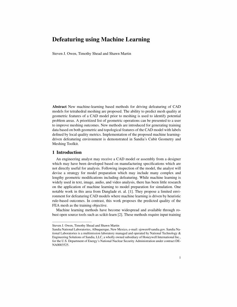
Fig. 1 Small curve in model that requires de-featuring before meshing
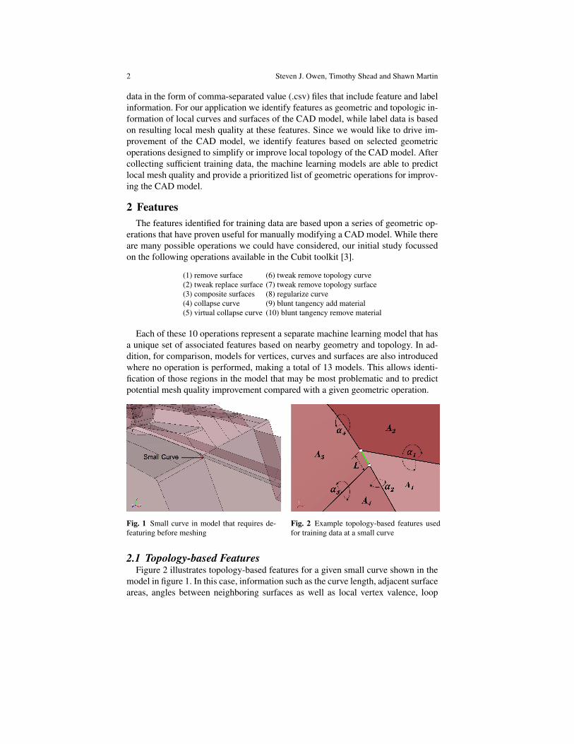
Fig. 2 Example topology-based features usedfor training data at a small curve
2.1 Topology-based FeaturesFigure 2 illustrates topology-based features for a given small curve shown in the
model in figure 1. In this case, information such as the curve length, adjacent surfaceareas, angles between neighboring surfaces as well as local vertex valence, loop
Defeaturing using Machine Learning 3
information and other information is used. The number of features used for eachmodel is based upon the geometric entities involved in the operation. For instance,a composite operation would include information about the surfaces involved in theoperation as well as those surrounding. In contrast, a collapse curve operation wouldinclude only information about the curve and its adjacent surfaces.
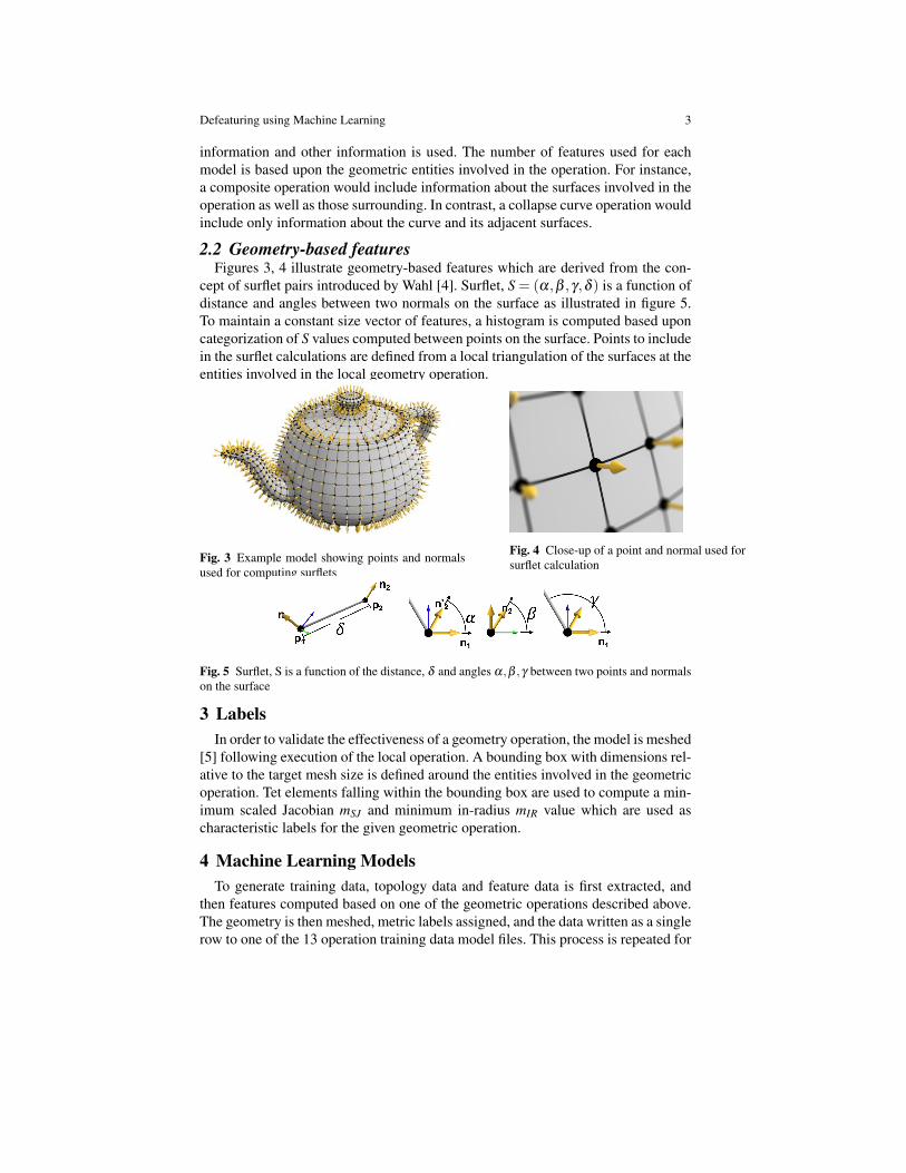
2.2 Geometry-based featuresFigures 3, 4 illustrate geometry-based features which are derived from the con-
cept of surflet pairs introduced by Wahl [4]. Surflet, S = (α,β ,γ,δ ) is a function ofdistance and angles between two normals on the surface as illustrated in figure 5.To maintain a constant size vector of features, a histogram is computed based uponcategorization of S values computed between points on the surface. Points to includein the surflet calculations are defined from a local triangulation of the surfaces at theentities involved in the local geometry operation.
Fig. 3 Example model showing points and normalsused for computing surflets
Fig. 4 Close-up of a point and normal used forsurflet calculation
Fig. 5 Surflet, S is a function of the distance, δ and angles α,β ,γ between two points and normalson the surface
3 LabelsIn order to validate the effectiveness of a geometry operation, the model is meshed
[5] following execution of the local operation. A bounding box with dimensions rel-ative to the target mesh size is defined around the entities involved in the geometricoperation. Tet elements falling within the bounding box are used to compute a min-imum scaled Jacobian mSJ and minimum in-radius mIR value which are used ascharacteristic labels for the given geometric operation.
4 Machine Learning ModelsTo generate training data, topology data and feature data is first extracted, and
then features computed based on one of the geometric operations described above.The geometry is then meshed, metric labels assigned, and the data written as a singlerow to one of the 13 operation training data model files. This process is repeated for
4 Steven J. Owen, Timothy Shead and Shawn Martin
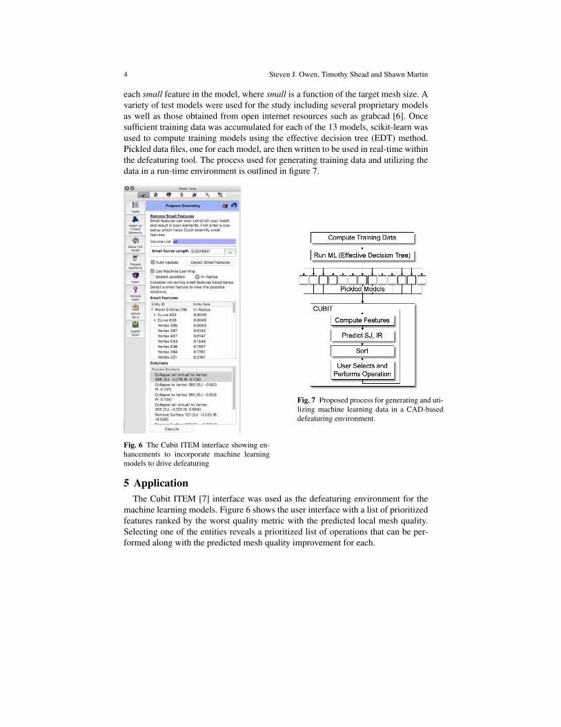
each small feature in the model, where small is a function of the target mesh size. Avariety of test models were used for the study including several proprietary modelsas well as those obtained from open internet resources such as grabcad [6]. Oncesufficient training data was accumulated for each of the 13 models, scikit-learn wasused to compute training models using the effective decision tree (EDT) method.Pickled data files, one for each model, are then written to be used in real-time withinthe defeaturing tool. The process used for generating training data and utilizing thedata in a run-time environment is outlined in figure 7.
Fig. 6 The Cubit ITEM interface showing en-hancements to incorporate machine learningmodels to drive defeaturing
Fig. 7 Proposed process for generating and uti-lizing machine learning data in a CAD-baseddefeaturing environment.
5 ApplicationThe Cubit ITEM [7] interface was used as the defeaturing environment for the
machine learning models. Figure 6 shows the user interface with a list of prioritizedfeatures ranked by the worst quality metric with the predicted local mesh quality.Selecting one of the entities reveals a prioritized list of operations that can be per-formed along with the predicted mesh quality improvement for each.
Defeaturing using Machine Learning 5
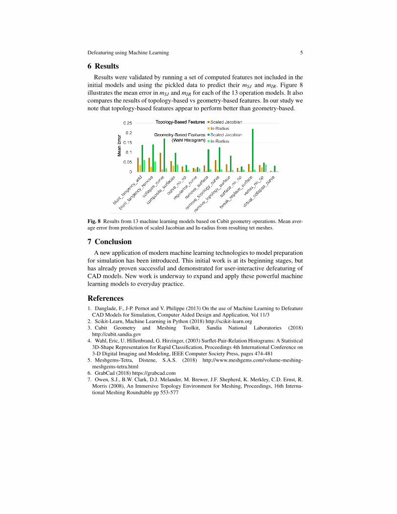
6 ResultsResults were validated by running a set of computed features not included in the
initial models and using the pickled data to predict their mSJ and mIR. Figure 8illustrates the mean error in mSJ and mIR for each of the 13 operation models. It alsocompares the results of topology-based vs geometry-based features. In our study wenote that topology-based features appear to perform better than geometry-based.
Fig. 8 Results from 13 machine learning models based on Cubit geometry operations. Mean aver-age error from prediction of scaled Jacobian and In-radius from resulting tet meshes.
7 ConclusionA new application of modern machine learning technologies to model preparation
for simulation has been introduced. This initial work is at its beginning stages, buthas already proven successful and demonstrated for user-interactive defeaturing ofCAD models. New work is underway to expand and apply these powerful machinelearning models to everyday practice.
References1. Danglade, F., J-P. Pernot and V. Philippe (2013) On the use of Machine Learning to Defeature
CAD Models for Simulation, Computer Aided Design and Application, Vol 11/32. Scikit-Learn, Machine Learning in Python (2018) http://scikit-learn.org3. Cubit Geometry and Meshing Toolkit, Sandia National Laboratories (2018)
http://cubit.sandia.gov4. Wahl, Eric, U. Hillenbrand, G. Hirzinger, (2003) Surflet-Pair-Relation Histograms: A Statistical
3D-Shape Representation for Rapid Classification, Proceedings 4th International Conference on3-D Digital Imaging and Modeling, IEEE Computer Society Press, pages 474-481
5. Meshgems-Tetra, Distene, S.A.S. (2018) http://www.meshgems.com/volume-meshing-meshgems-tetra.html
6. GrabCad (2018) https://grabcad.com7. Owen, S.J., B.W. Clark, D.J. Melander, M. Brewer, J.F. Shepherd, K. Merkley, C.D. Ernst, R.
Morris (2008), An Immersive Topology Environment for Meshing, Proceedings, 16th Interna-tional Meshing Roundtable pp 553-577