Embed Size (px)
Citation preview

Page 1 of 53 057-165 ISSUE: 9.0
DEEP SEA ELECTRONICS PLC
DSE890 and DSE891 WebNet® Gateway Manual
Document Number: 057-165
Author: Anthony Manton
DSE890 and DSE891 Webnet Gateway Manual
057-165 ISSUE: 9.0 Page 2 of 53
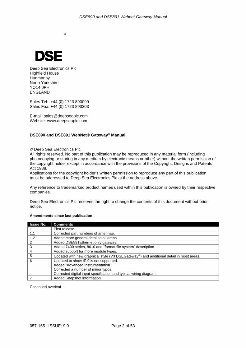
Deep Sea Electronics Plc Highfield House Hunmanby North Yorkshire YO14 0PH ENGLAND Sales Tel: +44 (0) 1723 890099 Sales Fax: +44 (0) 1723 893303 E-mail: [email protected] Website: www.deepseaplc.com DSE890 and DSE891 WebNet® Gateway® Manual © Deep Sea Electronics Plc All rights reserved. No part of this publication may be reproduced in any material form (including photocopying or storing in any medium by electronic means or other) without the written permission of the copyright holder except in accordance with the provisions of the Copyright, Designs and Patents Act 1988. Applications for the copyright holder’s written permission to reproduce any part of this publication must be addressed to Deep Sea Electronics Plc at the address above. Any reference to trademarked product names used within this publication is owned by their respective companies. Deep Sea Electronics Plc reserves the right to change the contents of this document without prior notice. Amendments since last publication
Issue No. Comments
1 First release.
1.1 Corrected part numbers of antennae.
1.2 Added more general detail to all areas.
2 Added DSE891Ethernet only gateway.
3 Added 7400 series, 8610 and “format file system” description.
4 Added support for more module types.
5 Updated with new graphical style (V3 DSEGateway®) and additional detail in most areas.
6 Updated to show IE 9 is not supported. Added “Advanced Instrumentation”. Corrected a number of minor typos. Corrected digital input specification and typical wiring diagram.
7 Added Snapshot information.
Continued overleaf…
Page 3 of 53 057-165 ISSUE: 9.0
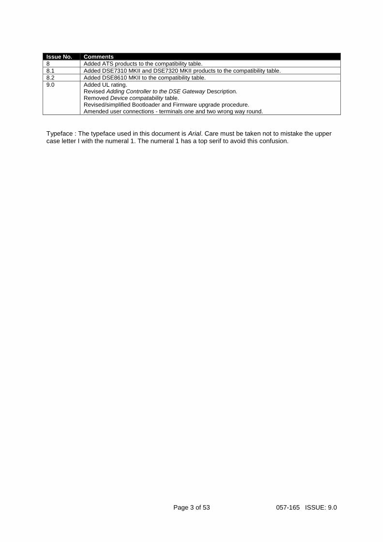
Issue No. Comments
8 Added ATS products to the compatibility table.
8.1 Added DSE7310 MKII and DSE7320 MKII products to the compatibility table.
8.2 Added DSE8610 MKII to the compatibility table.
9.0 Added UL rating. Revised Adding Controller to the DSE Gateway Description. Removed Device compatability table. Revised/simplified Bootloader and Firmware upgrade procedure. Amended user connections - terminals one and two wrong way round.
Typeface : The typeface used in this document is Arial. Care must be taken not to mistake the upper case letter I with the numeral 1. The numeral 1 has a top serif to avoid this confusion.
DSE890 and DSE891 Webnet Gateway Manual
057-165 ISSUE: 9.0 Page 4 of 53
Table of Contents
1 INTRODUCTION .................................................................................................. 6 1.1 BIBLIOGRAPHY ...................................................................................................................... 7
2 SPECIFICATIONS ............................................................................................... 8 2.1 TEMPERATURE ...................................................................................................................... 8
2.1.1 OPERATING TEMPERATURE ......................................................................................... 8 2.1.2 STORAGE TEMPERATURE ............................................................................................. 8
2.2 POWER SUPPLY ..................................................................................................................... 8 2.3 CONFIGURABLE I/O ............................................................................................................... 8
2.3.1 OUTPUTS ......................................................................................................................... 8 2.3.2 INPUTS ............................................................................................................................. 8
2.4 TERMINAL SPECIFICATION .................................................................................................. 9 2.5 SIM CARD CONNECTOR ........................................................................................................ 9 2.6 GSM CONNECTOR ................................................................................................................. 9 2.7 GPS CONNECTOR ................................................................................................................ 10 2.8 USB HOST CONNECTOR ..................................................................................................... 11 2.9 RS232 CONNECTOR............................................................................................................. 11
2.9.1 NULL MODEM CABLE WIRING ..................................................................................... 11 2.10 RS485 CONNECTOR ......................................................................................................... 12 2.11 ETHERNET CONNECTOR ................................................................................................ 12 2.12 DIMENSIONS AND MOUNTING ........................................................................................ 13
3 INSTALLATION ................................................................................................. 14 3.1 USER CONNECTIONS .......................................................................................................... 14
3.1.1 CONNECTOR A – DC SUPPLY AND CONFIGURABLE OUTPUTS ............................. 14 3.1.2 CONNECTOR B – RS485 ............................................................................................... 14 3.1.3 GSM & GPS CONNECTIONS (DSE890 3G GATEWAY ONLY) .................................... 14
3.2 SIM CARD HOLDER (DSE890 3G GATEWAY ONLY) ........................................................ 15 3.2.1 HOW TO INSERT THE 3G (OR 2G) GPRS SIM CARD ................................................. 15
3.3 TYPICAL WIRING DIAGRAM ................................................................................................ 16 3.4 SYSTEM OVERVIEW............................................................................................................. 16 3.5 TYPICAL CONNECTION TO DSE CONTROLLERS ............................................................ 17
3.5.1 ADDING THE CONTROLLER TO THE DSE GATEWAY® ............................................. 17 3.5.2 DEVICE COMPATIBILITY ............................................................................................... 18 3.5.3 USB (SINGLE CONTROLLER) ....................................................................................... 19 3.5.4 RS232 (SINGLE CONTROLLER) ................................................................................... 19 3.5.5 RS485 (SINGLE CONTROLLER) ................................................................................... 20 3.5.6 RS485 (MULTIPLE CONTROLLER) ............................................................................... 20 3.5.7 ETHERNET (SINGLE CONTROLLER) ........................................................................... 21 3.5.8 ETHERNET (MULTIPLE CONTROLLER) ...................................................................... 21
3.6 TYPICAL CONNECTION TO DSEWEBNET® SERVER ...................................................... 22 3.6.1 DSEWEBNET® SERVER CONNECTION INFORMATION ........................................... 22 3.6.2 FIREWALL SETTINGS ................................................................................................... 22 3.6.3 VIA ETHERNET .............................................................................................................. 23 3.6.4 VIA GPRS (DSE890 3G GATEWAY ONLY) ................................................................... 23
4 CONTROLS AND INDICATIONS ...................................................................... 24 4.1 RESET PUSHBUTTON .......................................................................................................... 24 4.2 LED INDICATIONS ................................................................................................................ 24
5 SETUP ............................................................................................................... 25 5.1 BROWSER COMPATIBILITY ................................................................................................ 25
5.1.1 GOOGLE CHROME ........................................................................................................ 25 5.1.2 INTERNET EXPLORER .................................................................................................. 25 5.1.3 MOZILLA FIREFOX ........................................................................................................ 25 5.1.4 SMARTPHONE BROWSERS ......................................................................................... 25
5.2 CONNECTING TO THE GATEWAY MANAGEMENT PAGES ............................................. 26 5.3 STATUS ................................................................................................................................. 27
5.3.1 INFO ................................................................................................................................ 27
DSE890 and DSE891 Webnet Gateway Manual
Page 5 of 53 057-165 ISSUE: 9.0
5.3.4 LOCATION ...................................................................................................................... 31 5.3.5 I/O .................................................................................................................................... 31 5.3.6 MODBUS ......................................................................................................................... 31 5.3.7 DATA USAGE ................................................................................................................. 32
5.4 CONFIGURATION ................................................................................................................. 33 5.4.1 INFO ................................................................................................................................ 33 5.4.2 NETWORK ...................................................................................................................... 34 5.4.3 GSM (DSE890 GATEWAY ONLY).................................................................................. 35 5.4.4 LOCATION ...................................................................................................................... 36 5.4.5 I/O .................................................................................................................................... 37 5.4.6 TIME ................................................................................................................................ 37 5.4.7 FILE SYSTEM ................................................................................................................. 38 5.4.8 BOOTLOADER UPGRADE ............................................................................................. 39 5.4.9 FIRMWARE UPGRADE .................................................................................................. 40 5.4.10 HOW TO FORMAT A USB FLASH MEMORY STICK TO FAT ...................................... 40
5.5 MODULES CONNECTION .................................................................................................... 41 5.5.1 DSEWEBNET .................................................................................................................. 41 5.5.2 CUSTOM INSTRUMENTS .............................................................................................. 44 5.5.3 MODBUS ......................................................................................................................... 47
6 FAULT DIAGNOSIS .......................................................................................... 49
7 MAINTENANCE, SPARES, REPAIR, AND SERVICING .................................. 51
8 WARRANTY ...................................................................................................... 51
9 DISPOSAL ......................................................................................................... 51
Introduction
057-165 ISSUE: 9.0 Page 6 of 53
1 INTRODUCTION This document details the installation requirements of the DSE890 and DSE891 WebNet® Gateway (DSEGateway®). The manual forms part of the product and must be kept for the entire life of the product. If the product is passed or supplied to another party, ensure that this document is passed to them for reference purposes. This is not a controlled document. Any future updates of this document are included on the DSE website at www.deepseaplc.com The DSEGateway® is used in conjunction with supported DSE controllers to provide monitoring and communications to a DSEWebNet® Server. The DSEGateway® communicates to the connected controller(s), monitoring the instrumentation and operating state. If this data changes, the new data is logged in the DSEGateway®’‘s memory. Depending upon configuration, at regular intervals the logged data is transmitted by GPRS or Ethernet to the DSEWebNet® Server. The DSE890 3G Gateway connects to the DSEWebNet® Server by integral Ethernet connection and GPRS (2G or 3G mobile internet). Additionally, DSE890 includes GPS (satellite location) functionality. This is most suited for remote and/or mobile locations. The DSE891 Ethernet Gateway connects to the DSEWebNet® Server by integral Ethernet connection only. This is most suited for fixed installations where an ADSL / DSL cable broadband service is available. The DSEWebNet® Server is then interrogated via an internet connected PC and web browser or SmartPhone (App or Web browser) to allow viewing of historic data or for live viewing/control. DSEGateway® is setup using a PC and network cable as detailed later in this document. Additionally the DSEWebNet® server can send emails if configured to do so. Where DSE890 3G Gateway is used in conjunction with an appropriate SIM card, the DSEWebNet®
server can be configured to use the DSE890 Gateway to send SMS messages. This feature is not available when using DSE891 Ethernet Gateway. For details on accessing the DSEGateway® using the DSEWebNet® system, refer to DSE publication 057-168 DSEWebNet® Software Manual available from the DSE website at www.deepseaplc.com.
Introduction
Page 7 of 53 057-165 ISSUE: 9.0
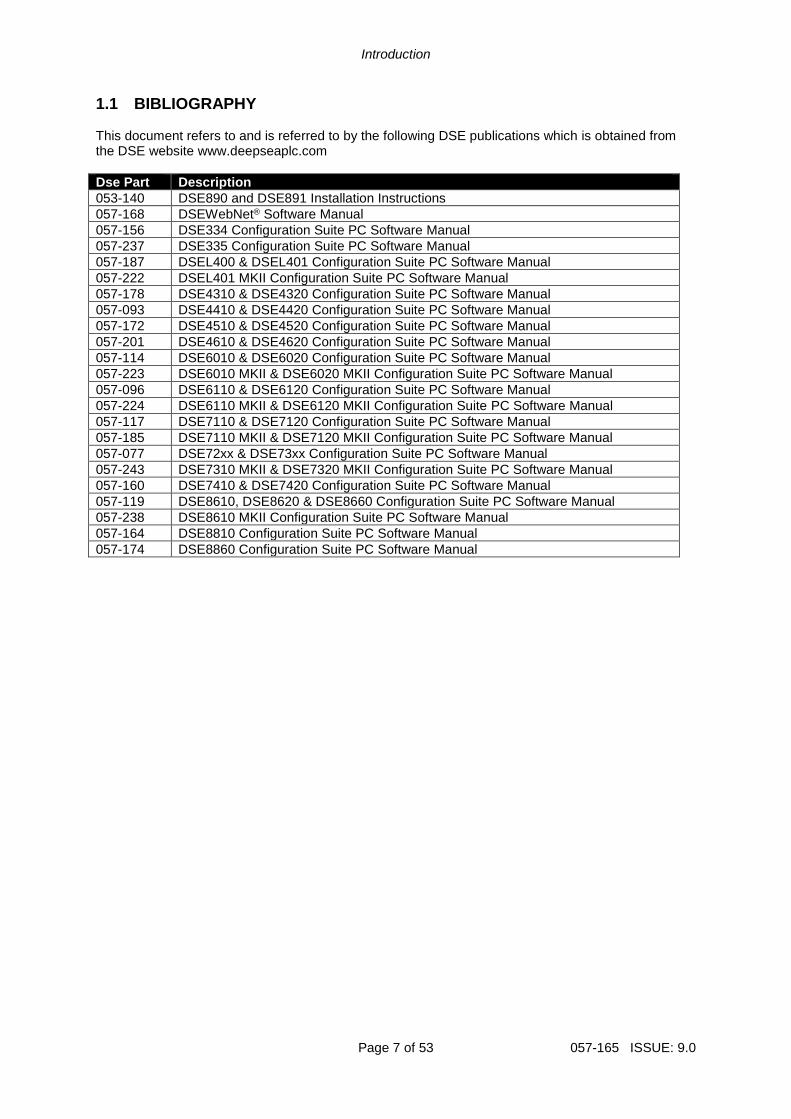
1.1 BIBLIOGRAPHY This document refers to and is referred to by the following DSE publications which is obtained from the DSE website www.deepseaplc.com
Dse Part Description
053-140 DSE890 and DSE891 Installation Instructions
057-168 DSEWebNet® Software Manual
057-156 DSE334 Configuration Suite PC Software Manual
057-237 DSE335 Configuration Suite PC Software Manual
057-187 DSEL400 & DSEL401 Configuration Suite PC Software Manual
057-222 DSEL401 MKII Configuration Suite PC Software Manual
057-178 DSE4310 & DSE4320 Configuration Suite PC Software Manual
057-093 DSE4410 & DSE4420 Configuration Suite PC Software Manual
057-172 DSE4510 & DSE4520 Configuration Suite PC Software Manual
057-201 DSE4610 & DSE4620 Configuration Suite PC Software Manual
057-114 DSE6010 & DSE6020 Configuration Suite PC Software Manual
057-223 DSE6010 MKII & DSE6020 MKII Configuration Suite PC Software Manual
057-096 DSE6110 & DSE6120 Configuration Suite PC Software Manual
057-224 DSE6110 MKII & DSE6120 MKII Configuration Suite PC Software Manual
057-117 DSE7110 & DSE7120 Configuration Suite PC Software Manual
057-185 DSE7110 MKII & DSE7120 MKII Configuration Suite PC Software Manual
057-077 DSE72xx & DSE73xx Configuration Suite PC Software Manual
057-243 DSE7310 MKII & DSE7320 MKII Configuration Suite PC Software Manual
057-160 DSE7410 & DSE7420 Configuration Suite PC Software Manual
057-119 DSE8610, DSE8620 & DSE8660 Configuration Suite PC Software Manual
057-238 DSE8610 MKII Configuration Suite PC Software Manual
057-164 DSE8810 Configuration Suite PC Software Manual
057-174 DSE8860 Configuration Suite PC Software Manual
Specifications
057-165 ISSUE: 9.0 Page 8 of 53
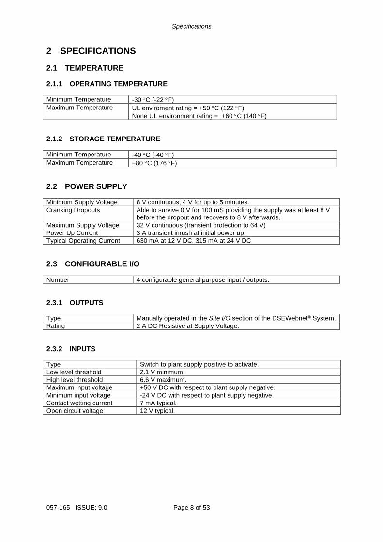
2 SPECIFICATIONS
2.1 TEMPERATURE
2.1.1 OPERATING TEMPERATURE
Minimum Temperature -30 C (-22 F)
Maximum Temperature UL enviroment rating = +50 C (122 F)
None UL environment rating = +60 C (140 F)
2.1.2 STORAGE TEMPERATURE
Minimum Temperature -40 C (-40 F)
Maximum Temperature +80 C (176 F)
2.2 POWER SUPPLY
Minimum Supply Voltage 8 V continuous, 4 V for up to 5 minutes.
Cranking Dropouts Able to survive 0 V for 100 mS providing the supply was at least 8 V before the dropout and recovers to 8 V afterwards.
Maximum Supply Voltage 32 V continuous (transient protection to 64 V)
Power Up Current 3 A transient inrush at initial power up.
Typical Operating Current 630 mA at 12 V DC, 315 mA at 24 V DC
2.3 CONFIGURABLE I/O
Number 4 configurable general purpose input / outputs.
2.3.1 OUTPUTS
Type Manually operated in the Site I/O section of the DSEWebnet® System.
Rating 2 A DC Resistive at Supply Voltage.
2.3.2 INPUTS
Type Switch to plant supply positive to activate.
Low level threshold 2.1 V minimum.
High level threshold 6.6 V maximum.
Maximum input voltage +50 V DC with respect to plant supply negative.
Minimum input voltage -24 V DC with respect to plant supply negative.
Contact wetting current 7 mA typical.
Open circuit voltage 12 V typical.
Specifications
Page 9 of 53 057-165 ISSUE: 9.0
2.4 TERMINAL SPECIFICATION
Connection Type Screw terminal, rising clamp, no internal spring
Min Cable Size 0.5 mm² (AWG 20)
Max Cable Size 2.5 mm² (AWG 14)
2.5 SIM CARD CONNECTOR
NOTE: GSM / GPRS service is not available with DSE891 Ethernet Gateway.
Provided to allow the DSE890 3G Gateway to be connected to a GPRS (internet over GSM) network. 3G or 2G SIM cards are supported. (Optional for use with GPRS support).
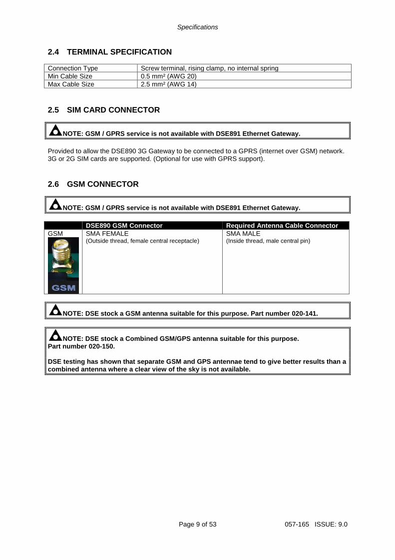
2.6 GSM CONNECTOR
NOTE: GSM / GPRS service is not available with DSE891 Ethernet Gateway.
DSE890 GSM Connector Required Antenna Cable Connector
GSM
SMA FEMALE (Outside thread, female central receptacle)
SMA MALE (Inside thread, male central pin)
NOTE: DSE stock a GSM antenna suitable for this purpose. Part number 020-141.
NOTE: DSE stock a Combined GSM/GPS antenna suitable for this purpose. Part number 020-150. DSE testing has shown that separate GSM and GPS antennae tend to give better results than a combined antenna where a clear view of the sky is not available.
Specifications
057-165 ISSUE: 9.0 Page 10 of 53
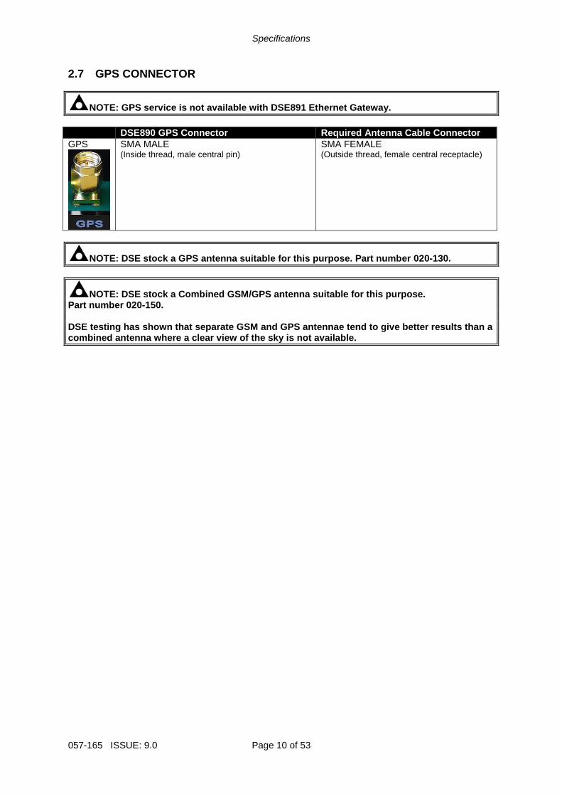
2.7 GPS CONNECTOR
NOTE: GPS service is not available with DSE891 Ethernet Gateway.
DSE890 GPS Connector Required Antenna Cable Connector
GPS
SMA MALE (Inside thread, male central pin)
SMA FEMALE (Outside thread, female central receptacle)
NOTE: DSE stock a GPS antenna suitable for this purpose. Part number 020-130.
NOTE: DSE stock a Combined GSM/GPS antenna suitable for this purpose. Part number 020-150. DSE testing has shown that separate GSM and GPS antennae tend to give better results than a combined antenna where a clear view of the sky is not available.
Specifications
Page 11 of 53 057-165 ISSUE: 9.0
2.8 USB HOST CONNECTOR
This USB type A socket provides support for connection to one DSE controller. Use USB type A to USB type B cable.
NOTE: DSE stock a USB suitable cable for this purpose. Part number 016-125.
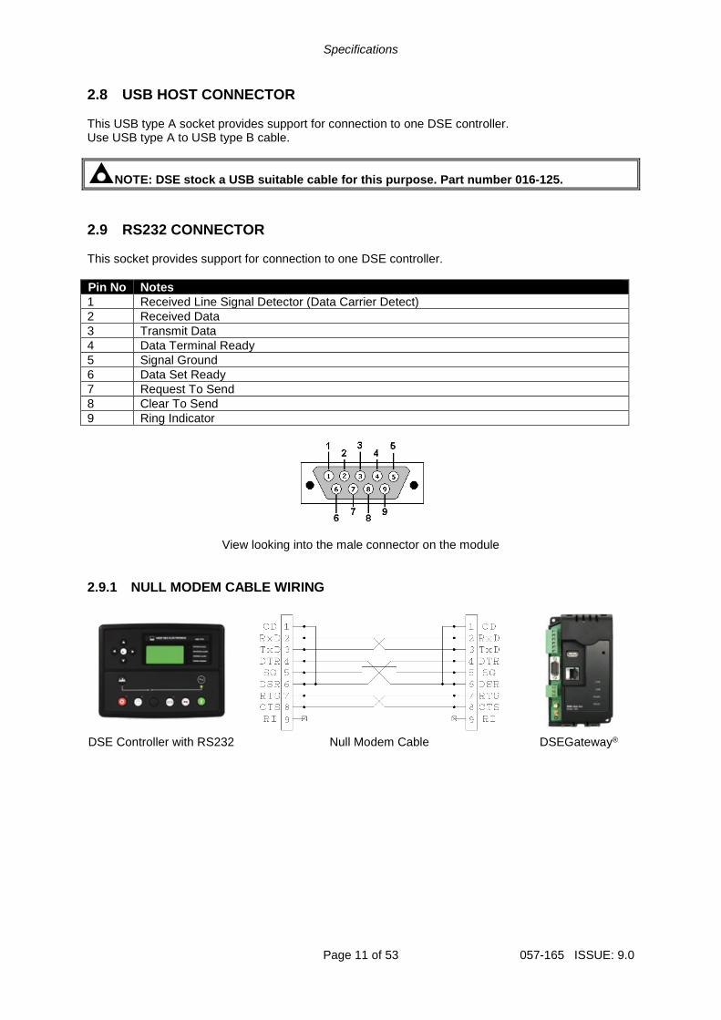
2.9 RS232 CONNECTOR This socket provides support for connection to one DSE controller.
Pin No Notes
1 Received Line Signal Detector (Data Carrier Detect)
2 Received Data
3 Transmit Data
4 Data Terminal Ready
5 Signal Ground
6 Data Set Ready
7 Request To Send
8 Clear To Send
9 Ring Indicator
View looking into the male connector on the module
2.9.1 NULL MODEM CABLE WIRING
DSE Controller with RS232 Null Modem Cable DSEGateway®
Specifications
057-165 ISSUE: 9.0 Page 12 of 53
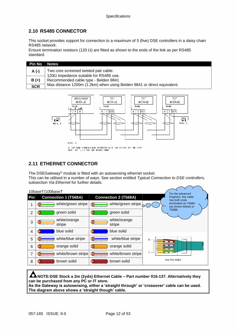
2.10 RS485 CONNECTOR This socket provides support for connection to a maximum of 5 (five) DSE controllers in a daisy chain RS485 network.
Ensure termination resistors (120 ) are fitted as shown to the ends of the link as per RS485 standard.
Pin No Notes
A (-) Two core screened twisted pair cable.
120 impedance suitable for RS485 use. Recommended cable type - Belden 9841 Max distance 1200m (1.2km) when using Belden 9841 or direct equivalent.
B (+)
SCR
2.11 ETHERNET CONNECTOR The DSEGateway® module is fitted with an autosensing ethernet socket. This can be utilised in a number of ways. See section entitled Typical Connection to DSE controllers, subsection Via Ethernet for further details. 10baseT/100baseT
Pin Connection 1 (T568A) Connection 2 (T568A)
1
white/green stripe
white/green stripe
2
green solid
green solid
3
white/orange stripe
white/orange stripe
4
blue solid
blue solid
5
white/blue stripe
white/blue stripe
6
orange solid
orange solid
7
white/brown stripe
white/brown stripe
8
brown solid
brown solid
NOTE:DSE Stock a 2m (2yds) Ethernet Cable – Part number 016-137. Alternatively they can be purchased from any PC or IT store. As the Gateway is autosensing, either a ‘straight through’ or ‘crossover’ cable can be used. The diagram above shows a ‘straight though’ cable.
For the advanced Engineer, this cable has both ends terminated as T568A (as shown below) or T568B.
Specifications
Page 13 of 53 057-165 ISSUE: 9.0
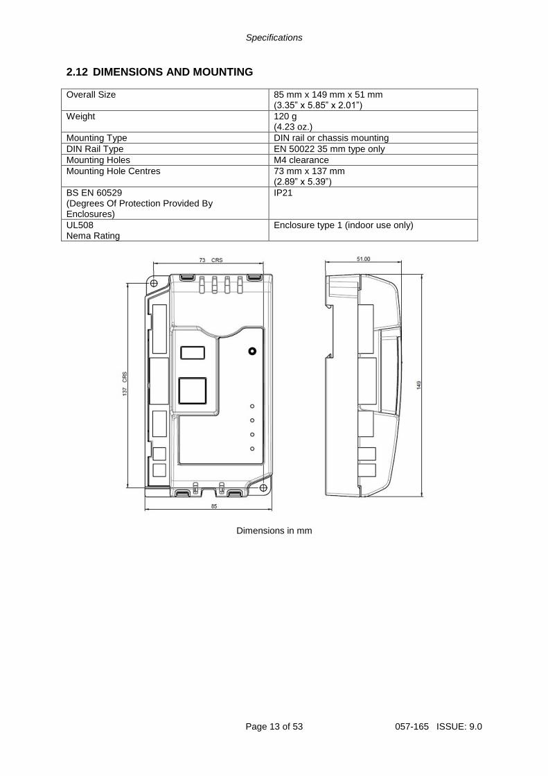
2.12 DIMENSIONS AND MOUNTING
Overall Size 85 mm x 149 mm x 51 mm (3.35” x 5.85” x 2.01”)
Weight 120 g (4.23 oz.)
Mounting Type DIN rail or chassis mounting
DIN Rail Type EN 50022 35 mm type only
Mounting Holes M4 clearance
Mounting Hole Centres 73 mm x 137 mm (2.89” x 5.39”)
BS EN 60529 (Degrees Of Protection Provided By Enclosures)
IP21
UL508 Nema Rating
Enclosure type 1 (indoor use only)
Dimensions in mm
Installation
Page 14 of 53 057-165 ISSUE: 9.0
3 INSTALLATION The DSEGateway® is designed to be mounted within a control panel, either on the panel DIN rail utilising the integral mounts, or chassis mounted, utilising the mounting holes. For dimension and mounting details, see the section entitled Specification, Dimensions elsewhere in this document.
3.1 USER CONNECTIONS
3.1.1 CONNECTOR A – DC SUPPLY AND CONFIGURABLE OUTPUTS
Terminal Function Recommended Size
1 DC supply negative 1.0 mm² (AWG18)
2 DC supply positive 1.0 mm² (AWG18)
3 Configurable Input / Output (I/O) 0.5 mm² (AWG20)
4 Configurable Input / Output (I/O) 0.5 mm² (AWG20)
5 Configurable Input / Output (I/O) 0.5 mm² (AWG20)
6 Configurable Input / Output (I/O) 0.5 mm² (AWG20)
3.1.2 CONNECTOR B – RS485
Terminal Function Recommended Size
A RS485 A 0.5 mm² (AWG20)
B RS485 B 0.5 mm² (AWG20)
SCR RS485 Screen
3.1.3 GSM & GPS CONNECTIONS (DSE890 3G GATEWAY ONLY)
Connector Designation
DSE890 Socket Type Required Antenna Cable Connector
GSM SMA FEMALE (Outside thread, female central receptacle)
SMA MALE (Inside thread, male central pin)
GPS SMA MALE (Inside thread, male central pin)
SMA FEMALE (Outside thread, female central receptacle)
Installation
Page 15 of 53 057-165 ISSUE: 9.0
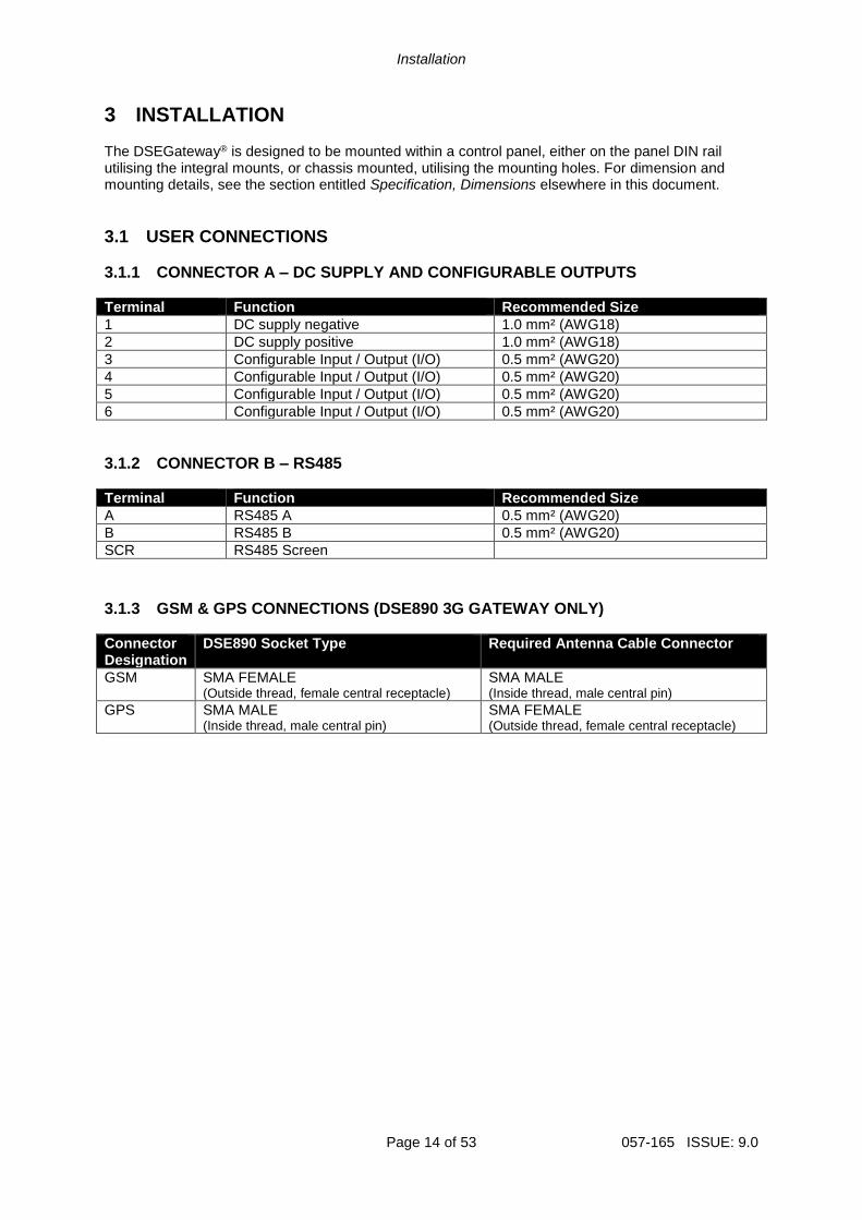
3.2 SIM CARD HOLDER (DSE890 3G GATEWAY ONLY)
3.2.1 HOW TO INSERT THE 3G (OR 2G) GPRS SIM CARD 1
2
3
4
Pull back the upper cover, it clicks as it unlocks.
Open the SIM card holder, it hinges towards you.
Slide in the SIM card, ensuring the “edge cutout” is as shown
Close the cover, press it down and slide it as shown until it clicks into place.
Installation
057-165 ISSUE: 9.0 Page 16 of 53
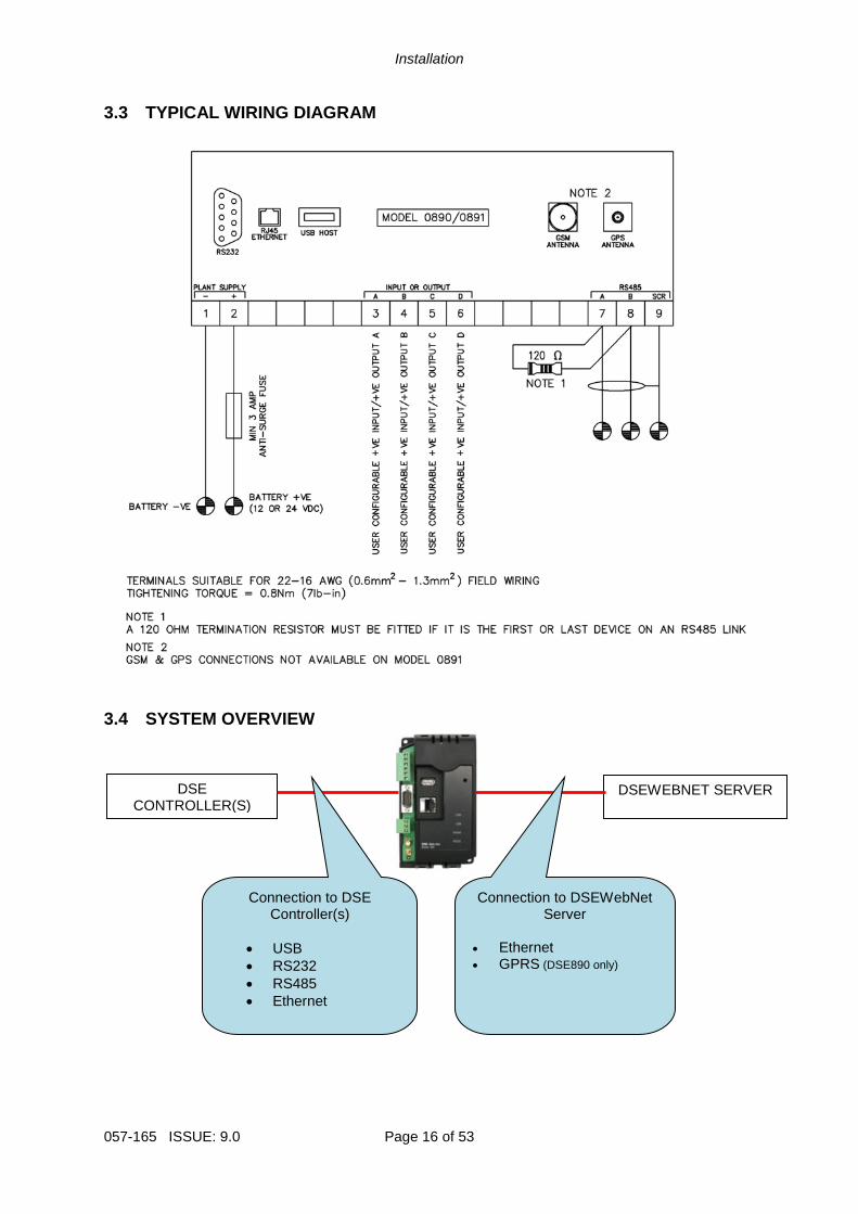
3.3 TYPICAL WIRING DIAGRAM
3.4 SYSTEM OVERVIEW
DSE CONTROLLER(S)
DSEWEBNET SERVER
Connection to DSE Controller(s)
• USB
• RS232
• RS485
• Ethernet
Connection to DSEWebNet Server
• Ethernet • GPRS (DSE890 only)
Installation
Page 17 of 53 057-165 ISSUE: 9.0
3.5 TYPICAL CONNECTION TO DSE CONTROLLERS This section shows how to connect DSE controllers to the gateway device. For details on how to connect the gateway to the server, see section entitled Typical connections to gateway server.
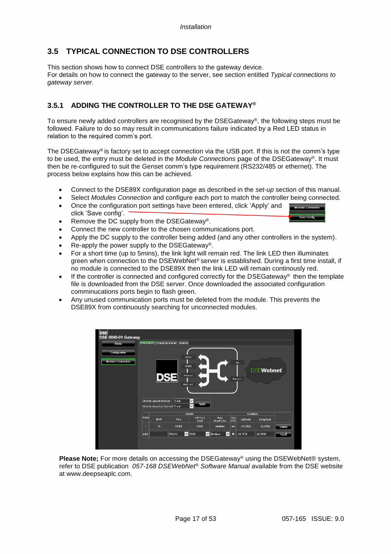
3.5.1 ADDING THE CONTROLLER TO THE DSE GATEWAY® To ensure newly added controllers are recognised by the DSEGateway®, the following steps must be followed. Failure to do so may result in communications failure indicated by a Red LED status in relation to the required comm’s port. The DSEGateway® is factory set to accept connection via the USB port. If this is not the comm’s type to be used, the entry must be deleted in the Module Connections page of the DSEGateway®. It must then be re-configured to suit the Genset comm’s type requirement (RS232/485 or ethernet). The process below explains how this can be achieved.
• Connect to the DSE89X configuration page as described in the set-up section of this manual.
• Select Modules Connection and configure each port to match the controller being connected.
• Once the configuration port settings have been entered, click ‘Apply’ and click ‘Save config’.
• Remove the DC supply from the DSEGateway®.
• Connect the new controller to the chosen communications port.
• Apply the DC supply to the controller being added (and any other controllers in the system).
• Re-apply the power supply to the DSEGateway®.
• For a short time (up to 5mins), the link light will remain red. The link LED then illuminates green when connection to the DSEWebNet® server is established. During a first time install, if no module is connected to the DSE89X then the link LED will remain continously red.
• If the controller is connected and configured correctly for the DSEGateway® then the template file is downloaded from the DSE server. Once downloaded the associated configuration comminucations ports begin to flash green.
• Any unused communication ports must be deleted from the module. This prevents the DSE89X from continuously searching for unconnected modules.
Please Note; For more details on accessing the DSEGateway® using the DSEWebNet® system, refer to DSE publication 057-168 DSEWebNet® Software Manual available from the DSE website at www.deepseaplc.com.
Installation
057-165 ISSUE: 9.0 Page 18 of 53
3.5.2 DEVICE COMPATIBILITY For up to date information regarding device compatibility contact DSE technical support: Tel: +44 1723 890099 Fax: +44 1723 893303 Email: [email protected] Web: https://www.deepseaplc.com/support
Installation
Page 19 of 53 057-165 ISSUE: 9.0
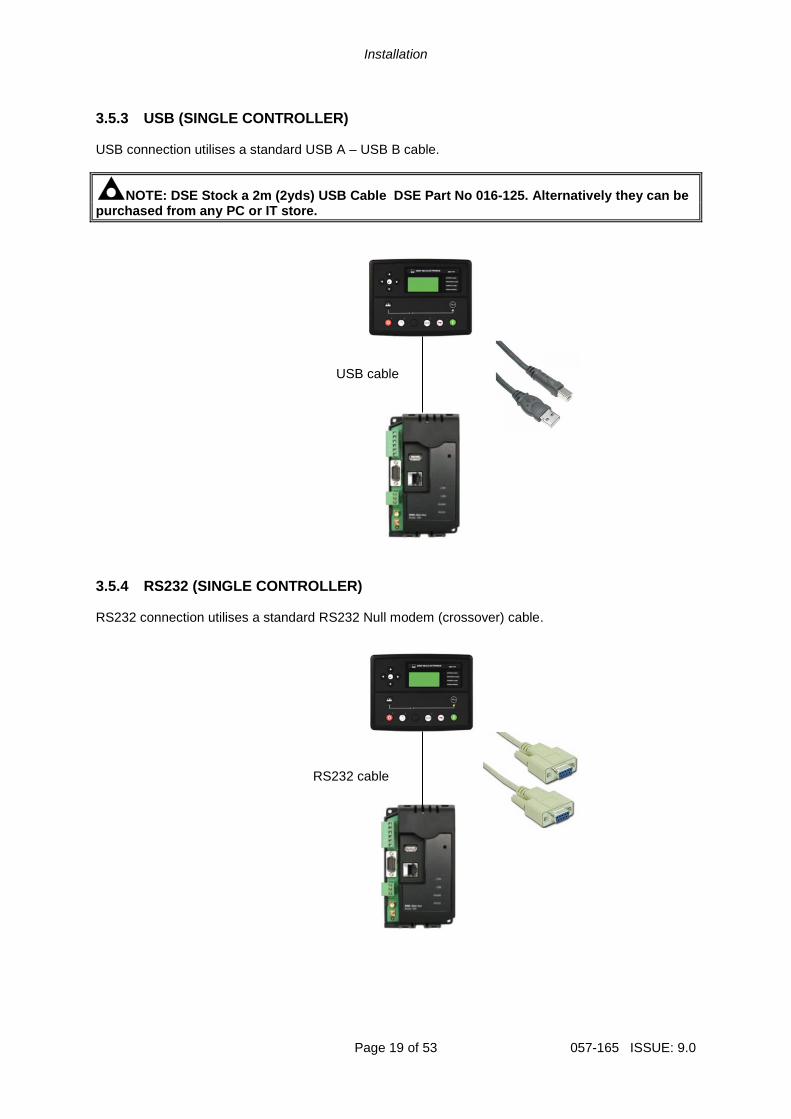
3.5.3 USB (SINGLE CONTROLLER)
USB connection utilises a standard USB A – USB B cable.
NOTE: DSE Stock a 2m (2yds) USB Cable DSE Part No 016-125. Alternatively they can be purchased from any PC or IT store.
3.5.4 RS232 (SINGLE CONTROLLER) RS232 connection utilises a standard RS232 Null modem (crossover) cable.
USB cable
RS232 cable

Installation
057-165 ISSUE: 9.0 Page 20 of 53
3.5.5 RS485 (SINGLE CONTROLLER)
RS485 connection utilises twisted pair RS485 cable with 120 termination resistors as per RS485 standard.
3.5.6 RS485 (MULTIPLE CONTROLLER) RS485 connection utilises twisted pair RS485 cable with 120 termination esistors as per RS485 standard.
NOTE: DSE stock and supply Belden cable 9841 which is a high quality 120 impedance cable suitable for RS485 use (DSE part number 016-030)
RS485 cable

Installation
Page 21 of 53 057-165 ISSUE: 9.0
3.5.7 ETHERNET (SINGLE CONTROLLER)
Ethernet connection utilises a standard Ethernet cable with RJ45 connectors.
3.5.8 ETHERNET (MULTIPLE CONTROLLER) Ethernet connection utilises a standard Ethernet cable with RJ45 connectors.
Network cable
Internet or Ethernet router/switch/hub

Installation
057-165 ISSUE: 9.0 Page 22 of 53
3.6 TYPICAL CONNECTION TO DSEWEBNET® SERVER The DSEGateway® communicates with the DSEWebNet® Server at regular (configurable) intervals to upload its logged data to the main database. This connection is via Ethernet (or internet) or GPRS (internet over the GSM cellular network).
NOTE: GSM / GPRS service is not available with DSE891 Ethernet Gateway.
3.6.1 DSEWEBNET® SERVER CONNECTION INFORMATION This sections contains information that may be useful to the I.T. or Network Managers on sites where the DSEGateway® is installed.
Item Description
Transmission Protocol All the data is sent using HTTP either on port 80 or 83. There is no ‘read’ action from the DSEWebNet® Server to the DSEGateway®. All data transfer streaming is initialized by the DSEGateway® and posted on the DSEWebNet® Server.
Data Encryption All the data is sent using a web socket protocol connection for real time data and http posts for historic data. The data for both of these is not encrypted but is not human readable. i.e. numbers and letters only rather than words. The DSEGateway®constantly contacts the DSEWebNet® Server, no connection is initialized by the Server.
Access Security All users have a different php session with “session takeover” attack prevention taken in to account. The passwords are hashed in MD5 format, the rest is in clear text.
3.6.2 FIREWALL SETTINGS To allow the DSEGateway® to communicate with the DSEWebNet® Server it is important than any network firewalls do not block access to the relevant ports. This is particularly important with wired connection to the internet however usually GSM networks do not include a network firewall. The DSE Server names and port numbers are listed below:
Domain name Port
www.dsewebnet.com 80
realtime.dsewebnet.com 83
historic.dsewebnet.com 80
To provide the best possible service, it is recommended that any firewall is configured to allow access to all subdomains on the dsewebnet.com domain as follows:
Domain name Ports
*.dsewebnet.com 80, 83
Installation
Page 23 of 53 057-165 ISSUE: 9.0
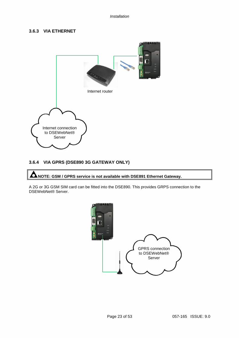
3.6.3 VIA ETHERNET
3.6.4 VIA GPRS (DSE890 3G GATEWAY ONLY)
NOTE: GSM / GPRS service is not available with DSE891 Ethernet Gateway.
A 2G or 3G GSM SIM card can be fitted into the DSE890. This provides GRPS connection to the DSEWebNet® Server.
Internet connection to DSEWebNet®
Server
GPRS connection to DSEWebNet®
Server
Internet router
Controls and Indications
Page 24 of 53 057-165 ISSUE: 9.0
4 CONTROLS AND INDICATIONS
4.1 RESET PUSHBUTTON
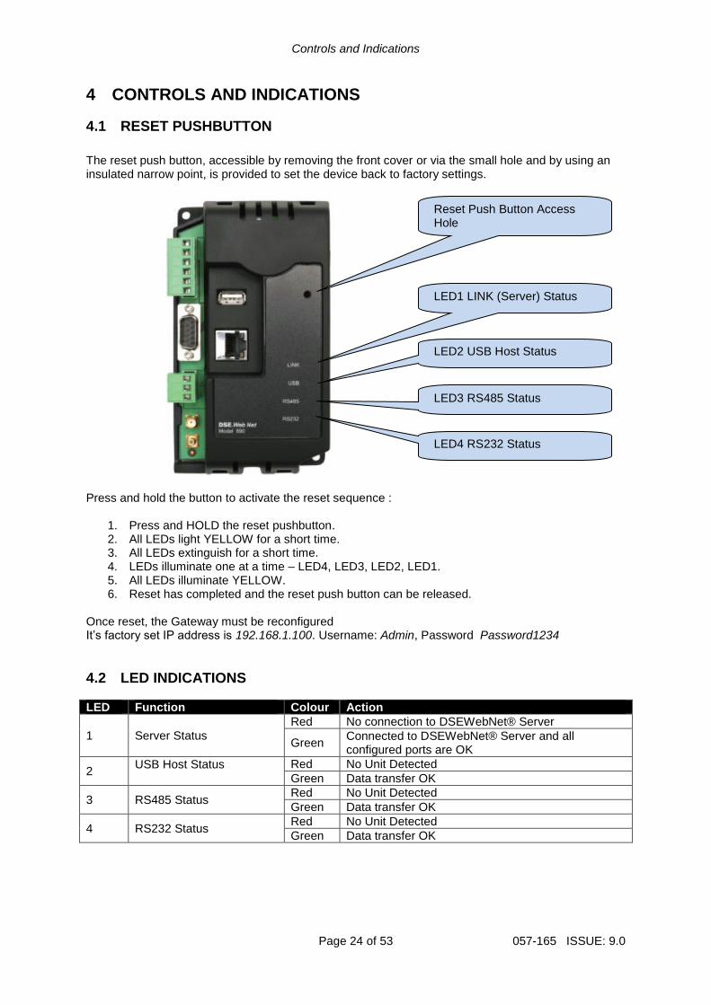
The reset push button, accessible by removing the front cover or via the small hole and by using an insulated narrow point, is provided to set the device back to factory settings.
Press and hold the button to activate the reset sequence :
1. Press and HOLD the reset pushbutton. 2. All LEDs light YELLOW for a short time. 3. All LEDs extinguish for a short time. 4. LEDs illuminate one at a time – LED4, LED3, LED2, LED1. 5. All LEDs illuminate YELLOW. 6. Reset has completed and the reset push button can be released.
Once reset, the Gateway must be reconfigured It’s factory set IP address is 192.168.1.100. Username: Admin, Password Password1234
4.2 LED INDICATIONS
LED Function Colour Action
1 Server Status
Red No connection to DSEWebNet® Server
Green Connected to DSEWebNet® Server and all configured ports are OK
2 USB Host Status
Red No Unit Detected
Green Data transfer OK
3 RS485 Status Red No Unit Detected
Green Data transfer OK
4 RS232 Status Red No Unit Detected
Green Data transfer OK
Reset Push Button Access Hole
LED1 LINK (Server) Status
LED2 USB Host Status
LED3 RS485 Status
LED4 RS232 Status
Setup
Page 25 of 53 057-165 ISSUE: 9.0
5 SETUP The DSEGateway® is setup using a PC with web browser and a ‘straight through’ or ‘crossover’ network cable.
5.1 BROWSER COMPATIBILITY
5.1.1 GOOGLE CHROME The DSEGateway® management pages are optimised for Google Chrome web browser.
5.1.2 INTERNET EXPLORER Internet Explorer 10 and above The DSEGateway® management pages are optimised for Internet Explorer 10 and above. Internet Explorer 9 and earlier Internet Explorer 9 and earlier versions are not supported.
5.1.3 MOZILLA FIREFOX The DSEGateway® management pages are optimised for Mozilla Firefox
5.1.4 SMARTPHONE BROWSERS Smartphone browsers are not supported by the DSEGateway® management pages.
Setup
057-165 ISSUE: 9.0 Page 26 of 53
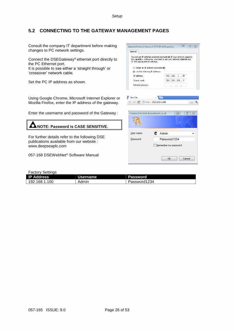
5.2 CONNECTING TO THE GATEWAY MANAGEMENT PAGES
Consult the company IT department before making changes to PC network settings. Connect the DSEGateway® ethernet port directly to the PC Ethernet port. It is possible to sse either a ‘straight through’ or ‘crossover’ network cable. Set the PC IP address as shown.
Using Google Chrome, Microsoft Internet Explorer or Mozilla Firefox, enter the IP address of the gateway.
Enter the username and password of the Gateway :
NOTE: Password is CASE SENSITIVE.
For further details refer to the following DSE publications available from our website : www.deepseaplc.com 057-168 DSEWebNet® Software Manual
Factory Settings
IP Address Username Password
192.168.1.100 Admin Password1234
Setup
Page 27 of 53 057-165 ISSUE: 9.0
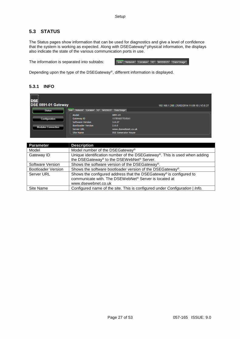
5.3 STATUS
The Status pages show information that can be used for diagnostics and give a level of confidence that the system is working as expected. Along with DSEGateway® physical information, the displays also indicate the state of the various communication ports in use.
The information is separated into subtabs:
Depending upon the type of the DSEGateway®, different information is displayed.
5.3.1 INFO
Parameter Description
Model Model number of the DSEGateway®
Gateway ID Unique identification number of the DSEGateway®. This is used when adding the DSEGateway® to the DSEWebNet® Server.
Software Version Shows the software version of the DSEGateway®.
Bootloader Version Shows the software bootloader version of the DSEGateway®.
Server URL Shows the configured address that the DSEGateway® is configured to communicate with. The DSEWebNet® Server is located at www.dsewebnet.co.uk
Site Name Configured name of the site. This is configured under Configuration | Info.
Setup
057-165 ISSUE: 9.0 Page 28 of 53
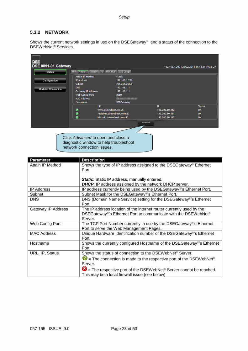
5.3.2 NETWORK Shows the current network settings in use on the DSEGateway® and a status of the connection to the DSEWebNet® Services.
Parameter Description
Attain IP Method Shows the type of IP address assigned to the DSEGateway® Ethernet Port.
Static: Static IP address, manually entered. DHCP: IP address assigned by the network DHCP server.
IP Address IP address currently being used by the DSEGateway®’s Ethernet Port.
Subnet Subnet Mask for the DSEGateway®’s Ethernet Port.
DNS DNS (Domain Name Service) setting for the DSEGateway®’s Ethernet Port.
Gateway IP Address The IP address location of the internet router currently used by the DSEGateway®’s Ethernet Port to communicate with the DSEWebNet® Server.
Web Config Port The TCP Port Number currently in use by the DSEGateway®’s Ethernet Port to serve the Web Management Pages.
MAC Address Unique Hardware Identification number of the DSEGateway®’s Ethernet Port.
Hostname Shows the currently configured Hostname of the DSEGateway®’s Ethernet Port.
URL, IP, Status Shows the status of connection to the DSEWebNet® Server.
= The connection is made to the respective port of the DSEWebNet® Server.
= The respective port of the DSEWebNet® Server cannot be reached. This may be a local firewall issue (see below)
Click Advanced to open and close a diagnostic window to help troubleshoot network connection issues.
Setup
Page 29 of 53 057-165 ISSUE: 9.0
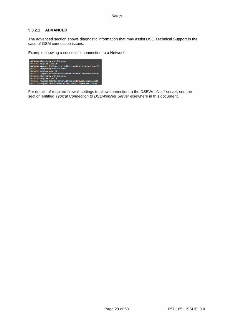
5.3.2.1 ADVANCED The advanced section shows diagnostic information that may assist DSE Technical Support in the case of GSM connection issues. Example showing a successful connection to a Network:
For details of required firewall settings to allow connection to the DSEWebNet ® server, see the section entitled Typical Connection to DSEWebNet Server elsewhere in this document.
Setup
057-165 ISSUE: 9.0 Page 30 of 53
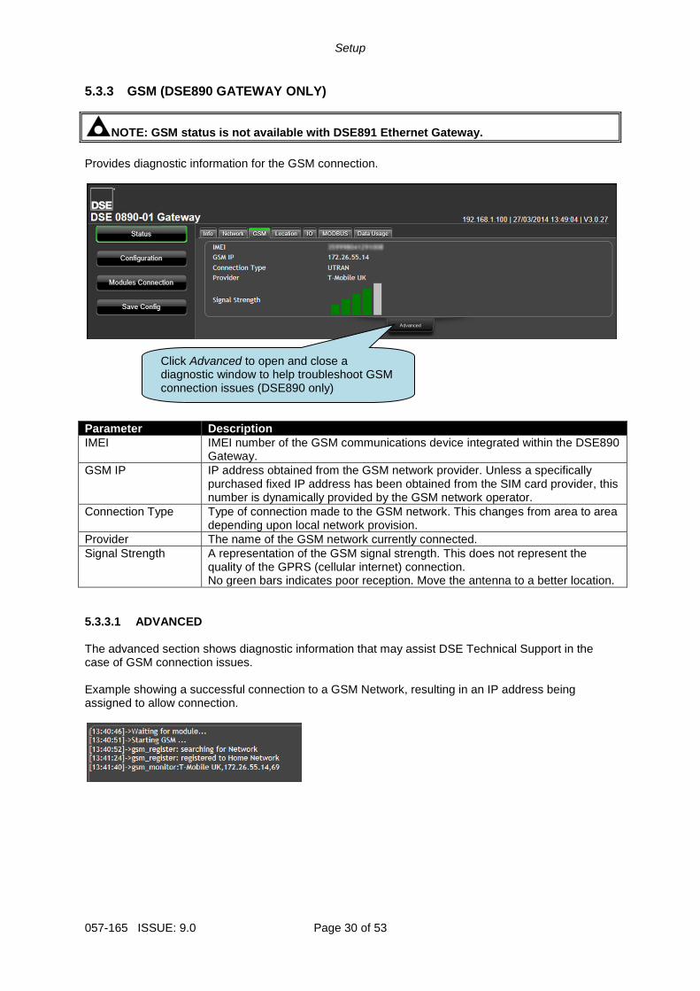
5.3.3 GSM (DSE890 GATEWAY ONLY)
NOTE: GSM status is not available with DSE891 Ethernet Gateway.
Provides diagnostic information for the GSM connection.
Parameter Description
IMEI IMEI number of the GSM communications device integrated within the DSE890 Gateway.
GSM IP IP address obtained from the GSM network provider. Unless a specifically purchased fixed IP address has been obtained from the SIM card provider, this number is dynamically provided by the GSM network operator.
Connection Type Type of connection made to the GSM network. This changes from area to area depending upon local network provision.
Provider The name of the GSM network currently connected.
Signal Strength A representation of the GSM signal strength. This does not represent the quality of the GPRS (cellular internet) connection. No green bars indicates poor reception. Move the antenna to a better location.
5.3.3.1 ADVANCED The advanced section shows diagnostic information that may assist DSE Technical Support in the case of GSM connection issues. Example showing a successful connection to a GSM Network, resulting in an IP address being assigned to allow connection.
Click Advanced to open and close a diagnostic window to help troubleshoot GSM connection issues (DSE890 only)
Setup
Page 31 of 53 057-165 ISSUE: 9.0
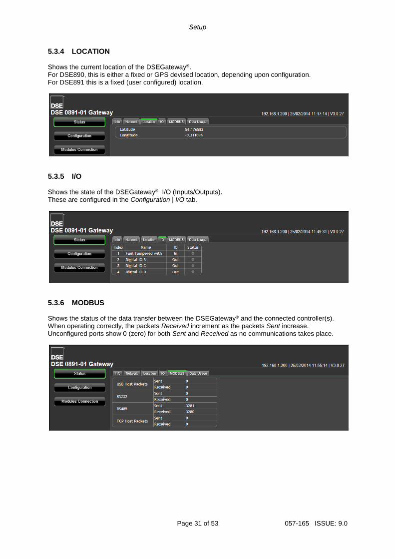
5.3.4 LOCATION Shows the current location of the DSEGateway®. For DSE890, this is either a fixed or GPS devised location, depending upon configuration. For DSE891 this is a fixed (user configured) location.
5.3.5 I/O Shows the state of the DSEGateway® I/O (Inputs/Outputs). These are configured in the Configuration | I/O tab.
5.3.6 MODBUS Shows the status of the data transfer between the DSEGateway® and the connected controller(s). When operating correctly, the packets Received increment as the packets Sent increase. Unconfigured ports show 0 (zero) for both Sent and Received as no communications takes place.
Setup
057-165 ISSUE: 9.0 Page 32 of 53
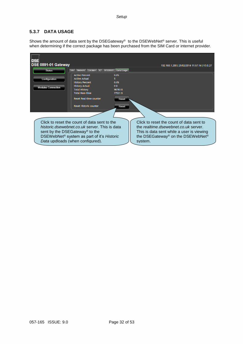
5.3.7 DATA USAGE Shows the amount of data sent by the DSEGateway® to the DSEWebNet® server. This is useful when determining if the correct package has been purchased from the SIM Card or internet provider.
Click to reset the count of data sent to the realtime.dsewebnet.co.uk server. This is data sent while a user is viewing the DSEGateway® on the DSEWebNet® system.
Click to reset the count of data sent to the historic.dsewebnet.co.uk server. This is data sent by the DSEGateway® to the DSEWebNet® system as part of it’s Historic Data updloads (when configured).
Setup
Page 33 of 53 057-165 ISSUE: 9.0
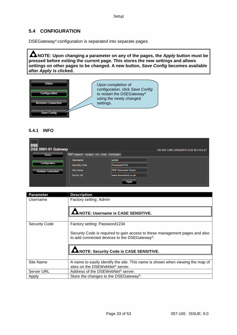
5.4 CONFIGURATION DSEGateway® configuration is separated into separate pages.
NOTE: Upon changing a parameter on any of the pages, the Apply button must be pressed before exiting the current page. This stores the new settings and allows settings on other pages to be changed. A new button, Save Config becomes available after Apply is clicked.
5.4.1 INFO
Parameter Description
Username Factory setting: Admin
NOTE: Username is CASE SENSITIVE.
Security Code Factory setting: Password1234 Security Code is required to gain access to these management pages and also to add connected devices to the DSEGateway®.
NOTE: Security Code is CASE SENSITIVE.
Site Name A name to easily identify the site. This name is shown when viewing the map of sites on the DSEWebNet® server.
Server URL Address of the DSEWebNet® server.
Apply Store the changes to the DSEGateway®.
Upon completion of configuration, click Save Config to restart the DSEGateway®
using the newly changed settings.
Setup
057-165 ISSUE: 9.0 Page 34 of 53
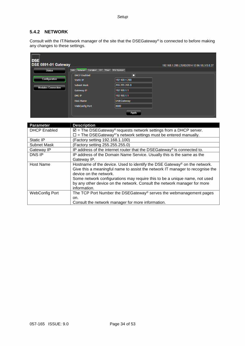
5.4.2 NETWORK
Consult with the IT/Network manager of the site that the DSEGateway® is connected to before making any changes to these settings.
Parameter Description
DHCP Enabled = The DSEGateway® requests network settings from a DHCP server. = The DSEGateway®’s network settings must be entered manually.
Static IP (Factory setting 192.168.1.100)
Subnet Mask (Factory setting 255.255.255.0)
Gateway IP IP address of the internet router that the DSEGateway® is connected to.
DNS IP IP address of the Domain Name Service. Usually this is the same as the Gateway IP.
Host Name Hostname of the device. Used to identify the DSE Gateway® on the network. Give this a meaningful name to assist the network IT manager to recognise the device on the network. Some network configurations may require this to be a unique name, not used by any other device on the network. Consult the network manager for more information.
WebConfig Port The TCP Port Number the DSEGateway® serves the webmanagement pages on. Consult the network manager for more information.
Setup
Page 35 of 53 057-165 ISSUE: 9.0
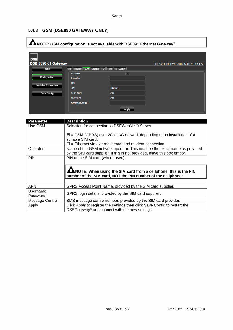
5.4.3 GSM (DSE890 GATEWAY ONLY)
NOTE: GSM configuration is not available with DSE891 Ethernet Gateway®.
Parameter Description
Use GSM Selection for connection to DSEWebNet® Server: = GSM (GPRS) over 2G or 3G network depending upon installation of a suitable SIM card. = Ethernet via external broadband modem connection.
Operator Name of the GSM network operator. This must be the exact name as provided by the SIM card supplier. If this is not provided, leave this box empty.
PIN PIN of the SIM card (where used).
NOTE: When using the SIM card from a cellphone, this is the PIN number of the SIM card, NOT the PIN number of the cellphone!
APN GPRS Access Point Name, provided by the SIM card supplier.
Username Password
GPRS login details, provided by the SIM card supplier.
Message Centre SMS message centre number, provided by the SIM card provider.
Apply Click Apply to register the settings then click Save Config to restart the DSEGateway® and connect with the new settings.
Setup
057-165 ISSUE: 9.0 Page 36 of 53
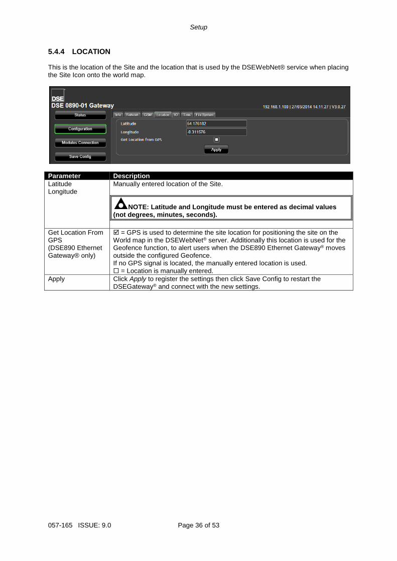
5.4.4 LOCATION This is the location of the Site and the location that is used by the DSEWebNet® service when placing the Site Icon onto the world map.
Parameter Description
Latitude Longitude
Manually entered location of the Site.
NOTE: Latitude and Longitude must be entered as decimal values (not degrees, minutes, seconds).
Get Location From GPS (DSE890 Ethernet Gateway® only)
= GPS is used to determine the site location for positioning the site on the World map in the DSEWebNet® server. Additionally this location is used for the Geofence function, to alert users when the DSE890 Ethernet Gateway® moves outside the configured Geofence. If no GPS signal is located, the manually entered location is used. = Location is manually entered.
Apply Click Apply to register the settings then click Save Config to restart the DSEGateway® and connect with the new settings.
Setup
Page 37 of 53 057-165 ISSUE: 9.0
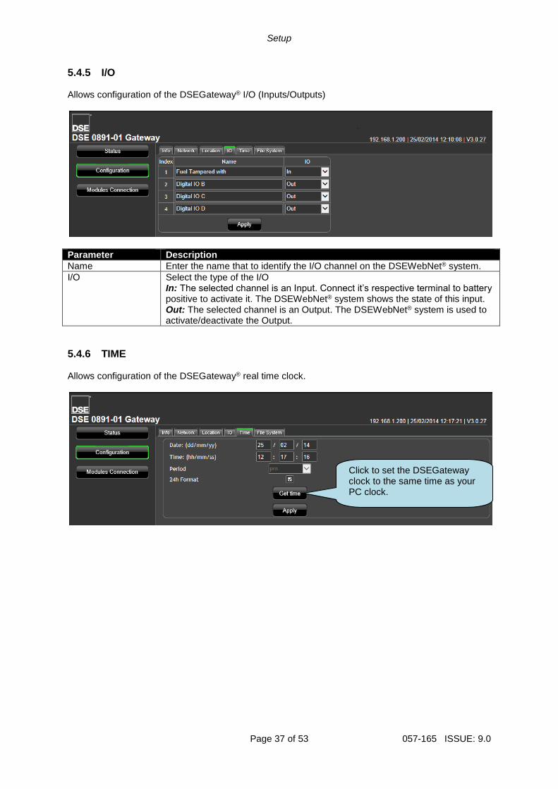
5.4.5 I/O Allows configuration of the DSEGateway® I/O (Inputs/Outputs)
Parameter Description
Name Enter the name that to identify the I/O channel on the DSEWebNet® system.
I/O Select the type of the I/O In: The selected channel is an Input. Connect it’s respective terminal to battery positive to activate it. The DSEWebNet® system shows the state of this input. Out: The selected channel is an Output. The DSEWebNet® system is used to activate/deactivate the Output.
5.4.6 TIME Allows configuration of the DSEGateway® real time clock.
Click to set the DSEGateway clock to the same time as your PC clock.
Setup
057-165 ISSUE: 9.0 Page 38 of 53
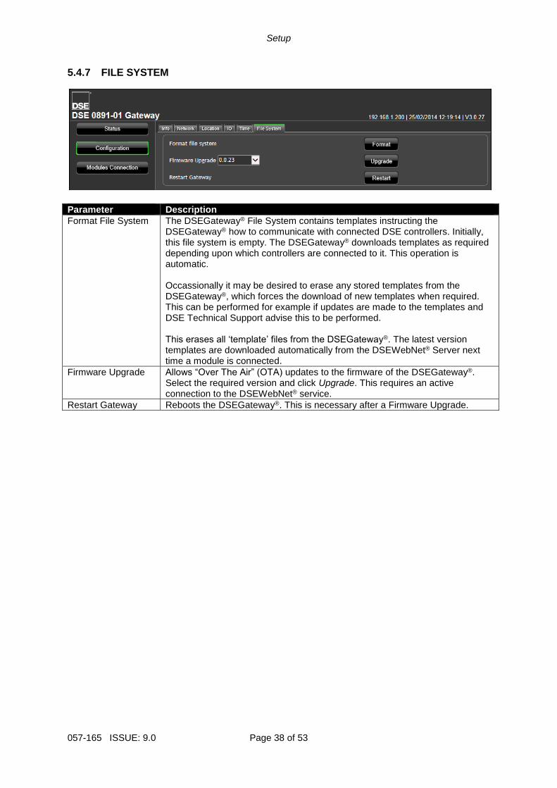
5.4.7 FILE SYSTEM
Parameter Description
Format File System The DSEGateway® File System contains templates instructing the DSEGateway® how to communicate with connected DSE controllers. Initially, this file system is empty. The DSEGateway® downloads templates as required depending upon which controllers are connected to it. This operation is automatic. Occassionally it may be desired to erase any stored templates from the DSEGateway®, which forces the download of new templates when required. This can be performed for example if updates are made to the templates and DSE Technical Support advise this to be performed. This erases all ‘template’ files from the DSEGateway®. The latest version templates are downloaded automatically from the DSEWebNet® Server next time a module is connected.
Firmware Upgrade Allows “Over The Air” (OTA) updates to the firmware of the DSEGateway®. Select the required version and click Upgrade. This requires an active connection to the DSEWebNet® service.
Restart Gateway Reboots the DSEGateway®. This is necessary after a Firmware Upgrade.

Setup
Page 39 of 53 057-165 ISSUE: 9.0
5.4.8 BOOTLOADER UPGRADE
NOTE: This process resets the DSEGateway® to factory settings.
Factory Settings
IP Address Username Password
192.168.1.100 Admin Password1234
The Bootloader is a small program within the DSEGateway® that handles the updating of the firmware within the device. Sometimes it may be necessary to update the Bootloader before the firmware can be updated. Bootloader upgrade files are available from Deep Sea Electronics PLC technical support. For example, to update from Version 1 or Version 2 firmware to Version 3, the Bootloader must first be updated. To do this Bootloader and Firmware update files are required as follows:
Description DSE890 3G DSEGateway DSE891 Ethernet Gateway
Bootloader update file 0890-01.bin 0891-01.bin
Firmware update files A890-01.bin E890-01.bin
A891-01.bin E891-01.bin
A USB flash memory stick formatted to FAT is alsro required. See Section entitled How to Format a USB Flash Memory Stick to FAT, elsewhere in this document. To update the Bootloader:
• Place the Bootloader update file onto the memory stick.
• Remove the DC power supply from the DSEGateway®.
• Insert the memory stick into the DSEGateway®.
• Reapply the DSE power supply to the DSEGateway®.
• Wait for the four status LEDs to stop cycling, then briefly remain green. The link LED status will remain RED whilst communications to DSEWebnet® are restabilished.
• The Bootloader updater file has been transferred to the DSEGateway®.
• Remove the DC power supply from the DSEGateway®.
• Remove the memory stick from the DSEGateway®.
• Reapply the DSE power supply to the DSEGateway®.
• The DSEGateway® Bootloader has been updated.
• Proceed to update the firmware as below.
USB flash memory stick inserted into the DSEGateway®
Setup
057-165 ISSUE: 9.0 Page 40 of 53
5.4.9 FIRMWARE UPGRADE When available, firmware upgrade files are available from Deep Sea Electronics PLC website www.deepseaplc.com. To do this, Firmware update files are required as follows:
Description DSE890 3G DSEGateway DSE891 Ethernet Gateway
Firmware update files A890-01.bin E890-01.bin
A891-01.bin E891-01.bin
A USB flash memory stick formatted to FAT is also required. See Section entitled How to Format a USB Flash Memory Stick to FAT, elsewhere in this document. To update the Firmware:
• Place the Firmware update files onto the USB memory stick.
• Remove the DC power supply from the DSEGateway®.
• Insert the memory stick into the DSEGateway®.
• Reapply the DSE power supply to the DSEGateway®.
• Wait for the four status LEDs to stop cycling, then briefly remain green. The link LED status will remain RED whilst communications to DSEWebnet® are restabilished.
• Remove the USB memory stick.
• The DSEGateway® Firmware has been updated.
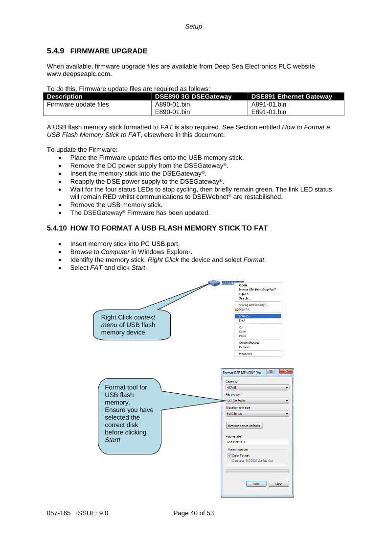
5.4.10 HOW TO FORMAT A USB FLASH MEMORY STICK TO FAT
• Insert memory stick into PC USB port.
• Browse to Computer in Windows Explorer.
• Identifty the memory stick, Right Click the device and select Format.
• Select FAT and click Start.
Right Click context menu of USB flash memory device
Format tool for USB flash memory. Ensure you have selected the correct disk before clicking Start!
Setup
Page 41 of 53 057-165 ISSUE: 9.0
5.5 MODULES CONNECTION
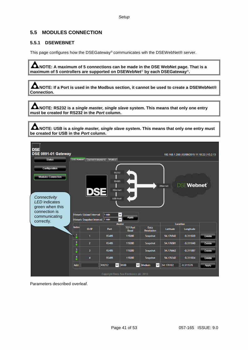
5.5.1 DSEWEBNET This page configures how the DSEGateway® communicates wih the DSEWebNet® server.
NOTE: A maximum of 5 connections can be made in the DSE WebNet page. That is a maximum of 5 controllers are supported on DSEWebNet® by each DSEGateway®.
NOTE: If a Port is used in the Modbus section, it cannot be used to create a DSEWebNet® Connection.
NOTE: RS232 is a single master, single slave system. This means that only one entry must be created for RS232 in the Port column.
NOTE: USB is a single master, single slave system. This means that only one entry must be created for USB in the Port column.
Parameters described overleaf.
Connectivity LED indicates green when this connection is communicating correctly.
Setup
057-165 ISSUE: 9.0 Page 42 of 53
Parameter Description
Historic upload interval
Determines the period at which the DSEGateway® uploads its datalog to the WebNet server. Shorter upload intervals increase the number of connections to the DSEWebNet® Server and may increase data costs depending upon the service contract with the internet provider.
Historic Snapshot Interval
Where Data Resolution is configured to be Snapshot, this determines the period at which the DSEGateway® uploads a snapshot of the instrumentation to the WebNet server. Shorter upload intervals increase the number of connections to the DSEWebNet® Server and may increase data costs depending upon the service contract with the internet provider.
5.5.1.1 MASTER These are the settings of the DSEGateway® port that is used to connect to the DSE controller).
Parameter Description
ID / IP When Port is set to Ethernet – IP address of the selected controller When Port is set to RS232/RS485 – Modbus slave address of the selected controller. Where multiple devices are connected (RS485), a unique ID must be used for each controller.
Port This is the port that is connected to the DSE controller. RS232: Connection to a single controller via RS232 NULL Modem (crossover) cable with female 9 pin D connector terminations. RS485: Connection to one or more RS485 enabled controllers using suitable RS485 connection cable. Ethernet: Connection to an Ethernet network of one or more controllers. USB: Single connection to a supported DSE controller by USB A – USB B cable.
TCP Port/Baud When Port is set to Ethernet – TCP port to use for Modbus (usually 502). Each separate entry must use a unique port number. When Port is set to RS232/RS485 – Baud rate of the selected controller.
Data Resolution High, Medium, Low, Snapshot This sets the level at what the DSEGateway® classes as a change in value. The DSEGateway® monitors the controller’s data and changes are logged in its internal memory. Selecting a higher resolution level increases the amount of logged data, hence increasing the amount of data that is sent to the WebNet server. This may increase data costs depending upon the service contract with the internet provider. Data is logged where the value changes by the configured amount. If there is no change in the data, there is no data to record in the log. Any logged data is uploaded to the DSE WebNet Server at the Historic Upload Interval. This may result in ‘empty’ reports if there is no logged data to upload.
Data Resolution
High Medium Low Snapshot
Factory setting 1% 5% 10% See Below
Snapshot: Where Data Resolution is configured to be Snapshot, this determines the period at which the DSEGateway® uploads a snapshot of the instrumentation to the WebNet server, regardless of how much it has changed. This setting prevents ‘empty reports’ that occur where no data is logged due to values changing by small amounts, below the setting of the Data Resolution.

Setup
Page 43 of 53 057-165 ISSUE: 9.0
5.5.1.2 LOCATION
Parameter Description
Use GPS (DSE890 3G Gateway only)
= Location of the controller is entered manually. Where multiple controllers are connected to the DSE890, it may be more appropriate to enter the location of each device manually. This allows each controller to show on the map at its specific location instead of showing all controllers at the same location as the DSE890 = GPS location is transmitted to the DSEWebNet® Server. This is used for live tracking and the Geofence feature of the DSEWebnet® system.
Latitude Longitude
Manually entered location of the selected controller. This is useful in cases where the controller is located some distance from the Gateway. For example the generator house may be at one side of a site, with the Gateway located in the IT department. Manually entering the location of the generator house shows this location on the DSEWebNet map, rather than the location of the IT department. Manually entered location (in degrees) of the DSE890 Locations East of the Greenwich Meridian = positive Locations West of the Greenwich Meridian = negative Locations North of the Equator = positive Locations South of the Equator = negative For example 54.18º N, 0.31º W is entered as Latitude: 54.18 Longitude: -0.31
Setup
057-165 ISSUE: 9.0 Page 44 of 53
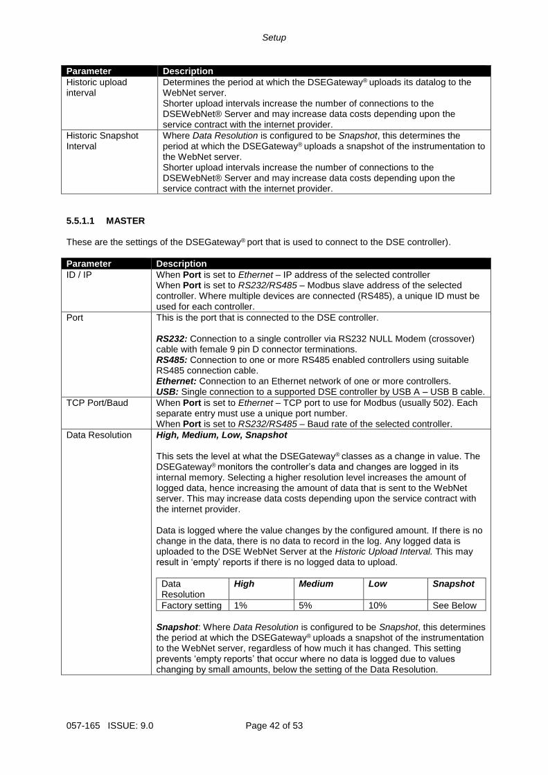
5.5.2 CUSTOM INSTRUMENTS This section is used to provide additional instruments to the DSEWebNet® system. The DSEGateway® is configured to read additional instruments from the connected controller(s). This information is then available for selection and display in the DSEWebNet® system.
Parameter Description
Module Index This refers to the Index column of the DSEWebNet configuration page. For example: Select Module Index: 1 to add/edit the Custom Instruments for the Module configured under Index 1 in the DSEWebNet page.
Index Index of the Custom Instrument. This is used when selecting the Custom Instrument for display in the DSEWebNet system.
Page Modbus Page number to read from.
Offset Register offset of the instrument to read.
Sign Type of the register to read. This must match the sign of the register as documented in the DSE Gencomm protocol document (bits/sign column). Signed: The register is a signed value (register contains negative and positive values). Unsigned: The resister is unsigned (register contains positive values only).
Size The size of the instrument value (in bits). This must match the bits of the register as documented in the DSE Gencomm protocol document (bits/sign column). 16: The instrument is contained within a single register (16 bits). 32: The instrument is contained within two registers (32 bits).
Example overleaf.
Setup
Page 45 of 53 057-165 ISSUE: 9.0
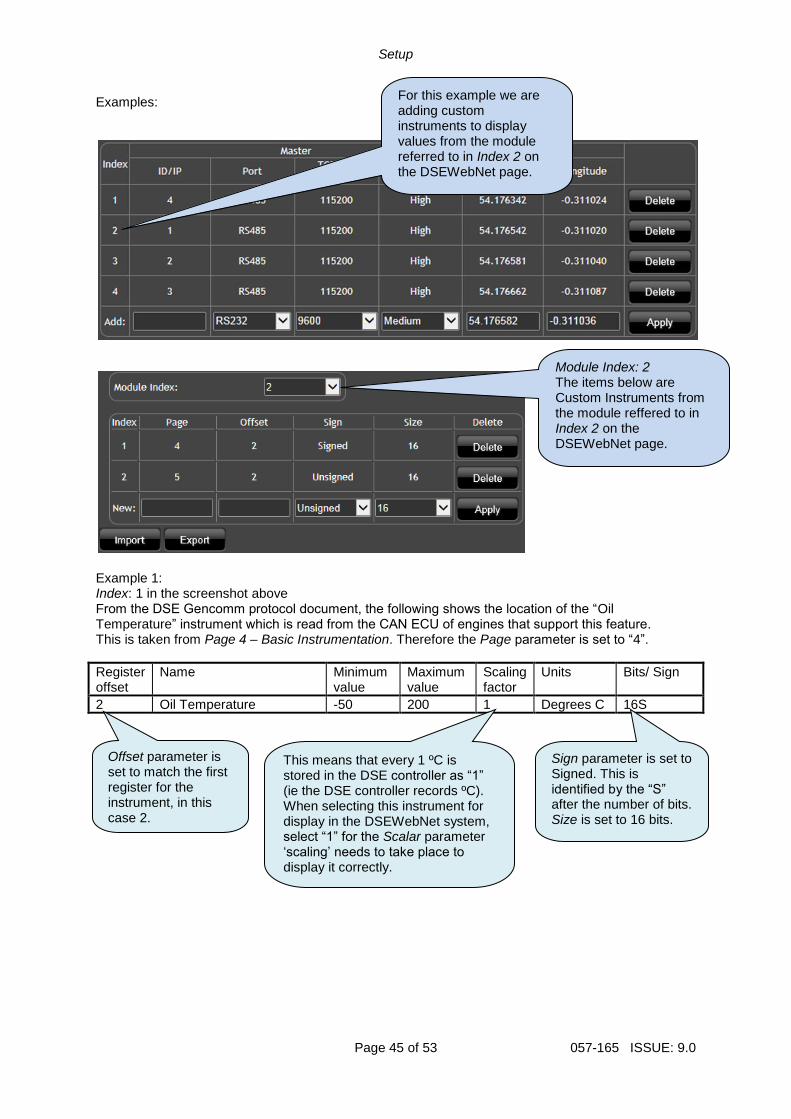
Examples:
Example 1: Index: 1 in the screenshot above From the DSE Gencomm protocol document, the following shows the location of the “Oil Temperature” instrument which is read from the CAN ECU of engines that support this feature. This is taken from Page 4 – Basic Instrumentation. Therefore the Page parameter is set to “4”.
Register offset
Name Minimum value
Maximum value
Scaling factor
Units Bits/ Sign
2 Oil Temperature -50 200 1 Degrees C 16S
Offset parameter is set to match the first register for the instrument, in this case 2.
Sign parameter is set to Signed. This is identified by the “S” after the number of bits. Size is set to 16 bits.
This means that every 1 ºC is stored in the DSE controller as “1” (ie the DSE controller records ºC). When selecting this instrument for display in the DSEWebNet system, select “1” for the Scalar parameter ‘scaling’ needs to take place to display it correctly.
Module Index: 2 The items below are Custom Instruments from the module reffered to in Index 2 on the DSEWebNet page.
For this example we are adding custom instruments to display values from the module referred to in Index 2 on the DSEWebNet page.
Setup
057-165 ISSUE: 9.0 Page 46 of 53
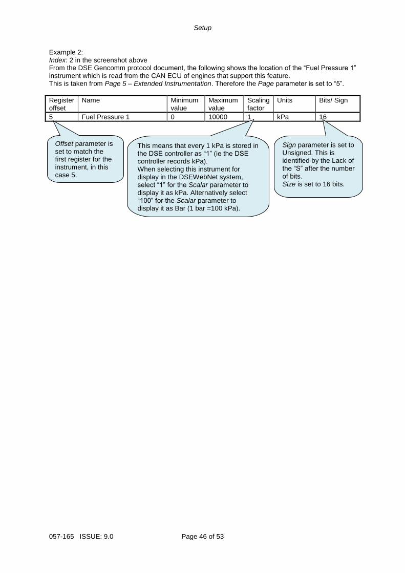
Example 2: Index: 2 in the screenshot above From the DSE Gencomm protocol document, the following shows the location of the “Fuel Pressure 1” instrument which is read from the CAN ECU of engines that support this feature. This is taken from Page 5 – Extended Instrumentation. Therefore the Page parameter is set to “5”.
Register offset
Name Minimum value
Maximum value
Scaling factor
Units Bits/ Sign
5 Fuel Pressure 1 0 10000 1 kPa 16
Offset parameter is set to match the first register for the instrument, in this case 5.
Sign parameter is set to Unsigned. This is identified by the Lack of the “S” after the number of bits. Size is set to 16 bits.
This means that every 1 kPa is stored in the DSE controller as “1” (ie the DSE controller records kPa). When selecting this instrument for display in the DSEWebNet system, select “1” for the Scalar parameter to display it as kPa. Alternatively select “100” for the Scalar parameter to display it as Bar (1 bar =100 kPa).
Setup
Page 47 of 53 057-165 ISSUE: 9.0
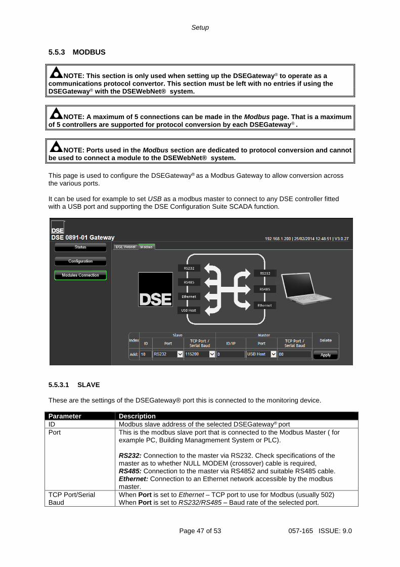
5.5.3 MODBUS
NOTE: This section is only used when setting up the DSEGateway® to operate as a communications protocol convertor. This section must be left with no entries if using the DSEGateway® with the DSEWebNet® system.
NOTE: A maximum of 5 connections can be made in the Modbus page. That is a maximum of 5 controllers are supported for protocol conversion by each DSEGateway® .
NOTE: Ports used in the Modbus section are dedicated to protocol conversion and cannot be used to connect a module to the DSEWebNet® system.
This page is used to configure the DSEGateway® as a Modbus Gateway to allow conversion across the various ports. It can be used for example to set USB as a modbus master to connect to any DSE controller fitted with a USB port and supporting the DSE Configuration Suite SCADA function.
5.5.3.1 SLAVE These are the settings of the DSEGateway® port this is connected to the monitoring device.
Parameter Description
ID Modbus slave address of the selected DSEGateway® port
Port This is the modbus slave port that is connected to the Modbus Master ( for example PC, Building Managmement System or PLC).
RS232: Connection to the master via RS232. Check specifications of the master as to whether NULL MODEM (crossover) cable is required, RS485: Connection to the master via RS4852 and suitable RS485 cable. Ethernet: Connection to an Ethernet network accessible by the modbus master.
TCP Port/Serial Baud
When Port is set to Ethernet – TCP port to use for Modbus (usually 502) When Port is set to RS232/RS485 – Baud rate of the selected port.
Setup
057-165 ISSUE: 9.0 Page 48 of 53
5.5.3.2 MASTER
These are the settings of the DSEGateway® port that is used to connect to the DSE controller.
Parameter Description
ID Modbus slave address of the connected DSE controller
Port This is the port that is connected to the DSE controller. RS232: Connection to a single controller via RS232 NULL Modem (crossover) cable with female 9 pin D connector terminations. RS485: Connection to one or more RS485 enabled controllers using suitable RS485 connection cable. Ethernet: Connection to an Ethernet network of one or more controllers. USB: Single connection to a supported DSE controller by USB A – USB B cable.
NOTE: RS485 is a single master system. This means that only one entry must be created for RS485 in the Slave column. Each entry in the Master column must communicate with controllers with unique Slave ID’s.
NOTE: RS232 is a single master, single slave system. This means that only one entry must be created for RS232 in the Master and Slave columns.
NOTE: Where multiple Ethernet connections are configured, each must utilise a unique port number.
TCP Port/Serial Baud
When Port is set to Ethernet – TCP port to use for Modbus (usually 502). When Port is set to RS232/RS485 – Baud rate of the selected controller.
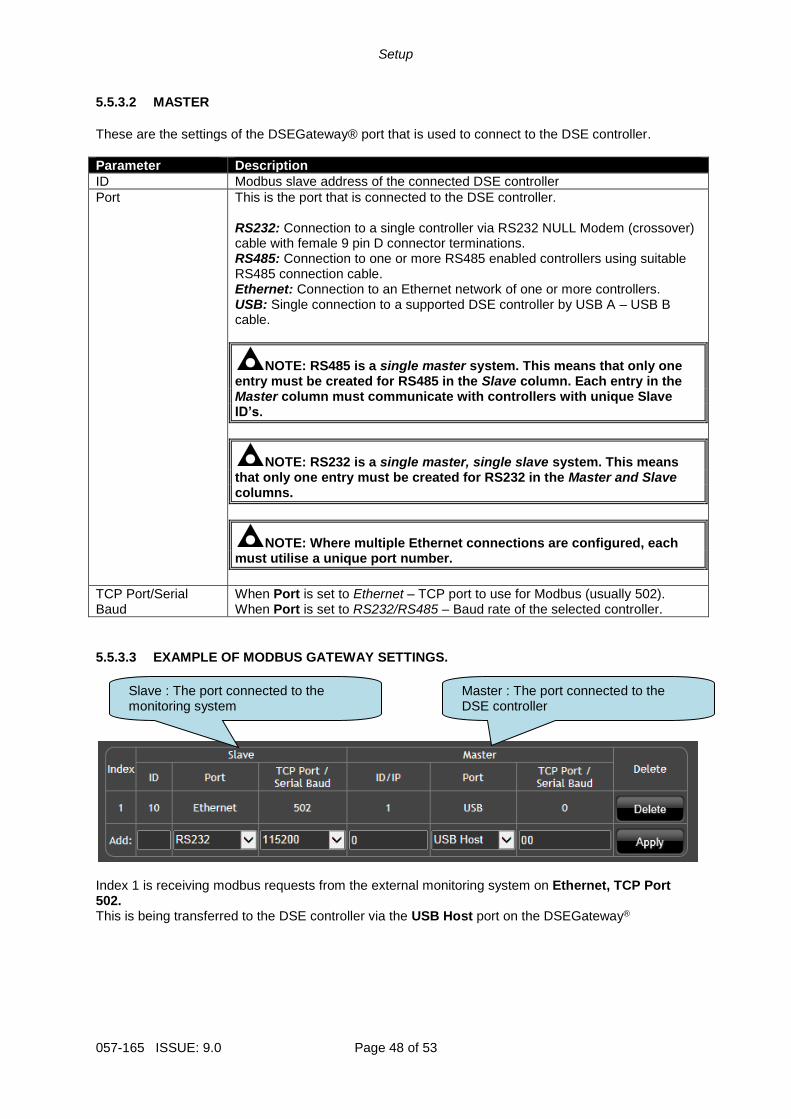
5.5.3.3 EXAMPLE OF MODBUS GATEWAY SETTINGS.
Index 1 is receiving modbus requests from the external monitoring system on Ethernet, TCP Port 502. This is being transferred to the DSE controller via the USB Host port on the DSEGateway®
Slave : The port connected to the monitoring system
Master : The port connected to the DSE controller
Fault Diagnosis
Page 49 of 53 057-165 ISSUE: 9.0
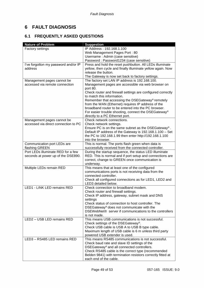
6 FAULT DIAGNOSIS
6.1 FREQUENTLY ASKED QUESTIONS
Nature of Problem Suggestion
Factory settings IP Address : 192.168.1.100 Web Management Pages Port : 80 Username : Admin (case sensitive) Password : Password1234 (case sensitive)
I’ve forgotton my password and/or IP address
Press and hold the reset pushbutton. All LEDs illuminate yellow, then cycle and finally illuminate yellow again. Now release the button. The Gateway is now set back to factory settings.
Management pages cannot be accessed via remote connection
The factory set LAN IP address is 192.168.100. Management pages are accessible via web browser on port 80. Check router and firewall settings are configured correctly to match this information. Remember that accessing the DSEGateway® remotely from the WAN (Ethernet) requires IP address of the broadband router to be entered into the PC browser. For easier trouble shooting, connect the DSEGateway®
directly to a PC Ethernet port.
Management pages cannot be accessed via direct connection to PC
Check network connections. Check network settings. Ensure PC is on the same subnet as the DSEGateway® . Default IP address of the Gateway is 192.168.1.100 – Set the PC to 192.168.1.99 then enter http://192.168.1.100 into the browser.
Communication port LEDs are flashing GREEN
This is normal. The ports flash green when data is successfully received from the connected controller.
Port LEDs illuminate RED for a few seconds at power up of the DSE890.
During the startup sequence, the status LED illuminate RED. This is normal and if port setup and connections are correct, change to GREEN once communication is underway.
Multiple LEDs remain RED This means that at least one of the configured communications ports is not receiving data from the connected controller. Check all configured connections as for LED1, LED2 and LED3 detailed below.
LED1 - LINK LED remains RED Check connection to broadband modem. Check router and firewall settings. Check IP address, gateway, subnet mask and DNS settings Check status of connection to host controller. The DSEGateway® does not communicate with the DSEWebNet® server if communications to the controllers is not made.
LED2 – USB LED remains RED This means USB communications is not successful. Check settings of the DSEGateway®. Check USB cable is USB A to USB B type cable. Maximum length of USB cable is 6 m unless third party powered USB extender is used.
LED3 – RS485 LED remains RED This means RS485 communications is not successful. Check baud rate and slave ID settings of the DSEGateway® and all connected controllers. Check RS485 cable is the correct type (recommended Belden 9841) with termination resistors correctly fitted at each end of the cable.
Fault Diagnosis
057-165 ISSUE: 9.0 Page 50 of 53
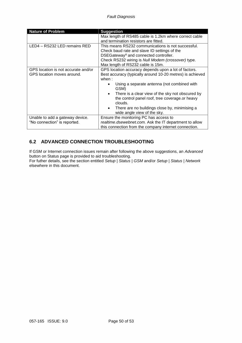
Nature of Problem Suggestion
Max length of RS485 cable is 1.2km where correct cable and termination resistors are fitted.
LED4 – RS232 LED remains RED This means RS232 communications is not successful. Check baud rate and slave ID settings of the DSEGateway® and connected controller. Check RS232 wiring is Null Modem (crossover) type. Max length of RS232 cable is 15m.
GPS location is not accurate and/or GPS location moves around.
GPS location accuracy depends upon a lot of factors. Best accuracy (typically around 10-20 metres) is achieved when :
• Using a separate antenna (not combined with GSM)
• There is a clear view of the sky not obscured by the control panel roof, tree coverage.or heavy clouds.
• There are no buildings close by, minimising a wide angle view of the sky.
Unable to add a gateway device. “No connection” is reported.
Ensure the monitoring PC has access to realtime.dsewebnet.com. Ask the IT department to allow this connection from the company internet connection.
6.2 ADVANCED CONNECTION TROUBLESHOOTING If GSM or Internet connection issues remain after following the above suggestions, an Advanced button on Status page is provided to aid troubleshooting. For futher details, see the section entitled Setup | Status | GSM and/or Setup | Status | Network elsewhere in this document.
Fault Diagnosis
Page 51 of 53 057-165 ISSUE: 9.0
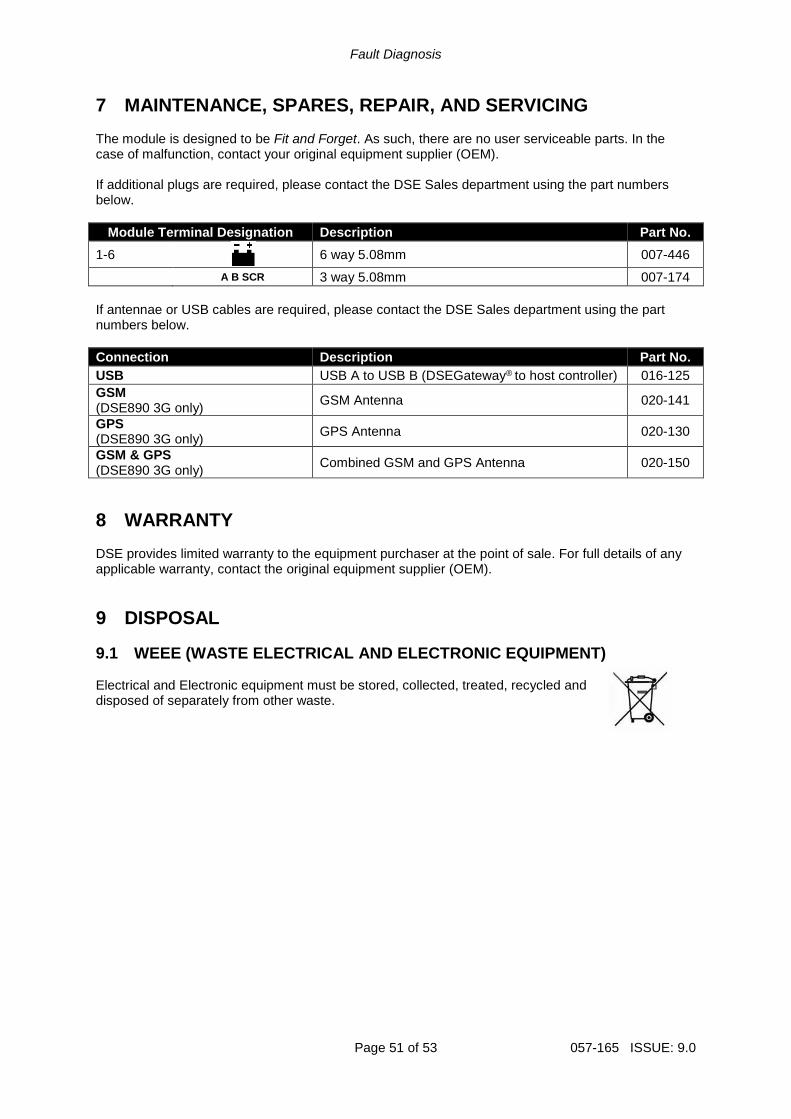
7 MAINTENANCE, SPARES, REPAIR, AND SERVICING The module is designed to be Fit and Forget. As such, there are no user serviceable parts. In the case of malfunction, contact your original equipment supplier (OEM). If additional plugs are required, please contact the DSE Sales department using the part numbers below.
Module Terminal Designation Description Part No.
1-6
6 way 5.08mm 007-446
A B SCR 3 way 5.08mm 007-174
If antennae or USB cables are required, please contact the DSE Sales department using the part numbers below.
Connection Description Part No.
USB USB A to USB B (DSEGateway® to host controller) 016-125
GSM (DSE890 3G only)
GSM Antenna 020-141
GPS (DSE890 3G only)
GPS Antenna 020-130
GSM & GPS (DSE890 3G only)
Combined GSM and GPS Antenna 020-150
8 WARRANTY DSE provides limited warranty to the equipment purchaser at the point of sale. For full details of any applicable warranty, contact the original equipment supplier (OEM).
9 DISPOSAL
9.1 WEEE (WASTE ELECTRICAL AND ELECTRONIC EQUIPMENT) Electrical and Electronic equipment must be stored, collected, treated, recycled and disposed of separately from other waste.

This Page Is Intentionally Blank

This Page is Intentionally Blank