Embed Size (px)
Citation preview

I S S U E 3 7 6 O C T O B E R 2 1 , 2 0 1 4
Apogee Components, Inc. — Your Source For Rocket Supplies That Will Take You To The “Peak-of-Flight”3355 Fillmore Ridge Heights
Colorado Springs, Colorado 80907-9024 USAwww.ApogeeRockets.com e-mail: [email protected]
Phone: 719-535-9335 Fax: 719-534-9050
Deciding Which Nose Cone Shape To Use for a High-Altitude Roket
Shrox Plan: “Bisix”
In This Issue
Cover Photo: DFR Technology’s Atlas V LRO/LCROSS kit takes to the sky. Get your own at: www.ApogeeRockets.com/Rocket_Kits/Rocket_Kits/Skill_Level_3_Kits/Atlas_V_LRO_LCROSS
Page 2 I S S U E 3 7 6 O C T O B E R 2 1 , 2 0 1 4
You can subscribe to receive this e-zine FREE at the Apogee Components web site (www.ApogeeRockets.com), or by sending an e-mail to: [email protected] with “SUB-SCRIBE” as the subject line of the message.
About this Newsletter Newsletter Staff
Writer: Tim Van MilliganLayout / Cover Artist: Tim Van MilliganProofreader: Erin Card
By Vicente Alvero and Hans Olaf Toft
Continued on page 3
BackgroundThe Sugar Shot to Space (SStS) rocket has a design
goal of reaching at least 100km in altitude, using a low per-formance sugar-nitrate propellant in a single stage rocket. In order to achieve this goal, it will be important to keep the drag loss at a minimum. Two strategies are being applied in this respect:
1. Dual phase rocket motor2. Minimum drag airframe
The dual phase motor splits the burn into two parts, divided by a coasting phase. This allows the rocket to save half of its propellant until it has passed through the denser part of the atmosphere.
The minimum drag airframe will improve the rockets altitude performance by keeping the energy loss in form of aerodynamic drag at a minimum. The overall shape of the rocket consists of a nose cone and a cylindrical rocket body and one set of fins. The dimensions of the cylindrical body are determined primarily by motor design restrictions and are as such outside the scope of this report. The dimen-
sions of the fins are to be deter-mined according to stability require-ments, and are also outside the scope of this re-port. The purpose of this report is to investigate the im-pact of shape and fineness ratio of the nose cone on the performance of the rocket, when it follows a trajectory profile that is rea-sonably realistic.
ConditionsThis investigation is based on Richard Nakka’s DPH47
configuration as detailed in Image 1A and 1B.
Design ToolsThis investigation is based on the “Aerolab” drag and
stability software and the “Launch” trajectory simulation software, both by Hans Olaf Toft.
“Aerolab” is used to calculate the coefficient of drag in the entire Mach range of relevance for the SStS for the configuration candidates of the airframe. The calculated drag coefficients are fed into the trajectory calculator, and the output is collected into a spread sheet for comparison. The trajectory simulator is being tricked to handle the dual phase configuration by adding a zero weight first stage and a dummy stage separation.
Although the overall purpose of this study is to set up a realistic scenario, some things are not known at this early stage. This affects the drag model in two ways:
1. Base drag reduction during powered flight is ignored as there is (yet) little knowledge of the nozzle dimensions.
2. The dimensions and number of fins are not yet
Deciding Which Nose Cone Shape To Use For A High-Altitude Rocket
Image 1A: Performance predictions of the DPH47 rocket.
Image 1B: Additional specification of the DPH47.
Page 3I S S U E 3 7 6 O C T O B E R 2 1 , 2 0 1 4
Nose Shapes for a High-Altitude RocketContinued from page 2
Continued on page 4
known. Furthermore, fin canting has been suggested but not (yet) specified, so the drag contribution from the fins has to be guesstimated. All the candidate configurations are being analysed with the same set of dummy fins that are assumed to provide a reasonable first order approxima-tion of the fins impact on the trajectory profile.
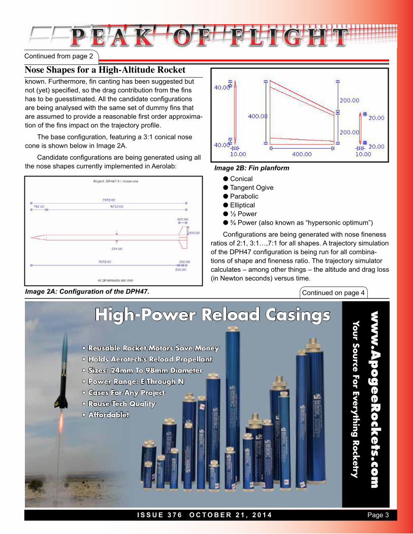
The base configuration, featuring a 3:1 conical nose cone is shown below in Image 2A.
Candidate configurations are being generated using all the nose shapes currently implemented in Aerolab:
High-Power Reload Casings ww
w.A
pogeeRock
ets.co
m
• Reusable Rocket Motors Save Money• Holds Aerotech’s Reload Propellant• Sizes: 24mm To 98mm Diameter• Power Range: E Through N• Cases For Any Project• Rouse-Tech Quality• Affordable!
Your Source For Everything R
ocketry
Image 2A: Configuration of the DPH47.
l Conicall Tangent Ogivel Parabolicl Ellipticall ½ Powerl ¾ Power (also known as “hypersonic optimum”)
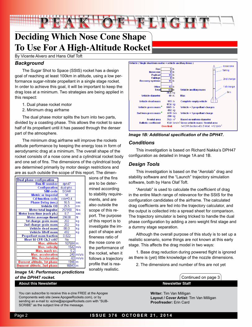
Configurations are being generated with nose fineness ratios of 2:1, 3:1…,7:1 for all shapes. A trajectory simulation of the DPH47 configuration is being run for all combina-tions of shape and fineness ratio. The trajectory simulator calculates – among other things – the altitude and drag loss (in Newton seconds) versus time.
Image 2B: Fin planform

Page 4 I S S U E 3 7 6 O C T O B E R 2 1 , 2 0 1 4
Continued from page 3
Nose Shapes for a High-Altitude Rocket
Continued on page 5
Trajectory profileThe main highlights of the trajectory when using the
standard drag model from Launch is:
1st phase burnout 8.70s 2232m 558m/s2nd phase ignition 16.50s 5882m 401m/s2nd phase burnout 25.20s 13664m 1638m/sApogee 164.75s 107689m 257m/s
The drag varies mostly with the Mach number, so one wants to check out the variation in Mach number as seen in Image 3.
One notable feature of this chart is that the Mach number stays constant be-tween approxi-mately 60 and 70km. This is not because the rocket travels at constant speed, but rather that the Mach veloc-ity decreases with altitude at
Continued on page 10
ww
w.A
pogeeRock
ets.co
m
www.ApogeeRockets.com/Rockets_By_Manufacturers
Looking For A Fun Rocket Kit?Roam In Our Forest of Over 190 Different Types
• Unique and exotic kits from over 20 different manufacturers
• Skill Levels range from “easy” to “fiendish”
• Sizes from 1/4A motor to level-2-high-power
• We build & fly them to find out what they’re like, saving you grief
• More new ones arriv-ing all the time
• Educational bulk packs available too
Image 3: Speed of the rocket versus altitude
the same rate as the rocket speed decreases. This is how-ever a curiosity, as the air drag is neglible at that altitude.
Different nose shapes are known to be optimal at differ-ent Mach ranges, so in order to select the best nose shape, it would be advisable to look at the velocity distribution as seen in Image 4.
Image 4: The amount of time the rocket spends at dif-ferent flight speeds.
Again, the Mach 3 peak is clearly visible. Even ignoring this, the rocket will spend approximately 50% of the trav-elling time at Mach 1.5+, where the hypersonic optimum
Page 5I S S U E 3 7 6 O C T O B E R 2 1 , 2 0 1 4
Continued from page 4
Nose Shapes for a High-Altitude Rocket
Continued on page 6
shape has minimum wave drag for any given fineness ratio. For comparison, the same rocket spends approximately 35% of the travelling time at transsonic speeds, where the hypersonic optimum shape is not the optimal choice.
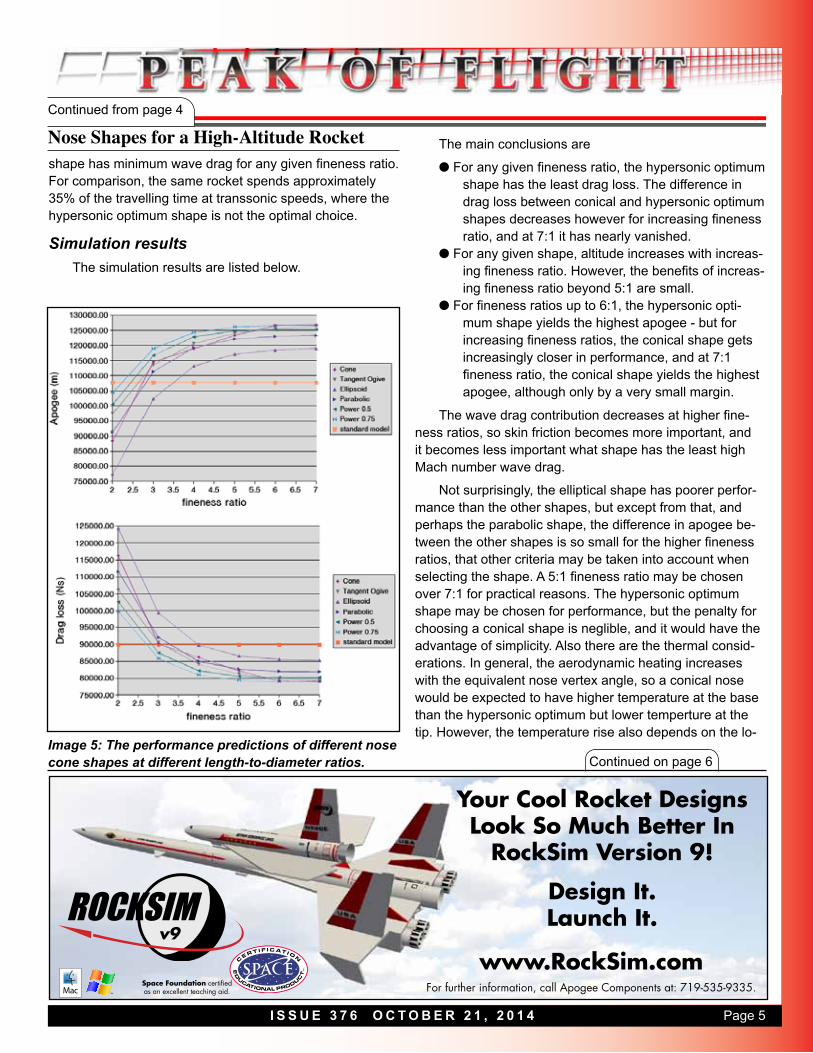
Simulation resultsThe simulation results are listed below.
The main conclusions are
l For any given fineness ratio, the hypersonic optimum shape has the least drag loss. The difference in drag loss between conical and hypersonic optimum shapes decreases however for increasing fineness ratio, and at 7:1 it has nearly vanished.
l For any given shape, altitude increases with increas-ing fineness ratio. However, the benefits of increas-ing fineness ratio beyond 5:1 are small.
l For fineness ratios up to 6:1, the hypersonic opti-mum shape yields the highest apogee - but for increasing fineness ratios, the conical shape gets increasingly closer in performance, and at 7:1 fineness ratio, the conical shape yields the highest apogee, although only by a very small margin.
The wave drag contribution decreases at higher fine-ness ratios, so skin friction becomes more important, and it becomes less important what shape has the least high Mach number wave drag.
Not surprisingly, the elliptical shape has poorer perfor-mance than the other shapes, but except from that, and perhaps the parabolic shape, the difference in apogee be-tween the other shapes is so small for the higher fineness ratios, that other criteria may be taken into account when selecting the shape. A 5:1 fineness ratio may be chosen over 7:1 for practical reasons. The hypersonic optimum shape may be chosen for performance, but the penalty for choosing a conical shape is neglible, and it would have the advantage of simplicity. Also there are the thermal consid-erations. In general, the aerodynamic heating increases with the equivalent nose vertex angle, so a conical nose would be expected to have higher temperature at the base than the hypersonic optimum but lower temperture at the tip. However, the temperature rise also depends on the lo-
Space Foundation certified as an excellent teaching aid. For further information, call Apogee Components at: 719-535-9335.
www.RockSim.comv9
Your Cool Rocket Designs Look So Much Better In
RockSim Version 9!
Design It.Launch It.
Image 5: The performance predictions of different nose cone shapes at different length-to-diameter ratios.
Page 6 I S S U E 3 7 6 O C T O B E R 2 1 , 2 0 1 4
Continued from page 5
Nose Shapes for a High-Altitude Rocketcal heat capacity, and the tip of a hypersonic optimum nose can have a larger heat capacity so it may still have the lowest skin temperature overall. A blunted cone could be a reasonable way of approximating the hypersonic optimum shape while keeping the simplicity of a cone.
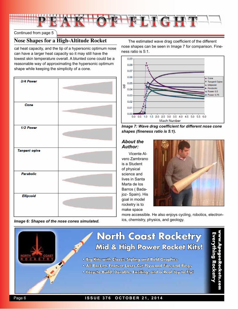
The estimated wave drag coefficient of the different nose shapes can be seen in Image 7 for comparison. Fine-ness ratio is 5:1.
North Coast RocketryMid & High Power Rocket Kits!
ww
w.A
pogeeRock
ets.co
mEverything
Rock
etry
• Big Kits with Classic Styling and Bold Graphics• All Rockets Feature Laser-Cut Plywood Fins and Rings • Easy-to-Build. Durable. Exciting, and a Real Joy to Fly!
Image 6: Shapes of the nose cones simulated.
Image 7: Wave drag coefficient for different nose cone shapes (fineness ratio is 5:1).
About the Author:
Vicente Al-vero Zambrano is a Student of physical science and lives in Santa Marta de los Barros ( Bada-joz- Spain). His goal in model rocketry is to make space more accessible. He also enjoys cycling, robotics, electron-ics, chemistry, physics, and geology.

Page 7I S S U E 3 7 6 O C T O B E R 2 1 , 2 0 1 4
Shrox Plan: The “Bisix”By Shrox
Electronics Hardware Installation Kit
ww
w.A
pog
eeRock
ets.com
Think of the convenience of getting everything to professionally install your dual-deployment or oth-er electronic payload into a e-bay of your rocket!
www.apogeerockets.com
Includes: nylon stand-offs, screws & nuts, wire, push-switch, drill & tap, ejection charge cannisters, barrier strips, wire ties, and step-by-step DVD instructions.
Download the RockSim file (which includes the parts list) and the decal file at: www.ApogeeRockets.com/Downloads/Bisix.zip
Join The NAR.orgMention Apogee Components