Embed Size (px)
Citation preview

March 27, 2017
Steve Whitmore
School of Engineering Science
Simon Fraser University
Burnaby, British Columbia
V5A 1S6
RE: ENSC 405W Design Specifications – SolarPathTM: Multi-sourced Renewable Energy System
Dear Dr. Whitmore,
Attached is a design specification document regarding the SolarPathTM renewable energy
system from Solentic Energy. Our intentions are to research, design and build a renewable
energy tile which will generate electricity through solar and mechanical methods. Both
methods will work synchronously in order to charge a connectable battery bank.
The purpose of the design specification is to give insight on the specific implementation of
SolarPathTM. These specifications outline the design for the physical aspects of the SolarPathTM
module and subsystems, as well as details about the circuitry for the electrical processes
performed by the product. This document will be used by our team as a reference during the
design, construction and testing of SolarPathTM.
Solentic Energy is comprised of five passionate engineering science students: Destiny Hsu,
Imran Kanji, Klein Gomes, Nolan Magee and Jin Xiong. If you should have any questions or
concerns relating to our requirements specification, please do not hesitate to email our
principle contact, Klein Gomes, at [email protected].
Sincerely,
Destiny Hsu
CEO
Solentic Energy

SolarPathTM
by
Design team: Destiny Hsu Klein Gomes Imran Kanji Nolan Magee Jin Xiong
Contact person: Klein Gomes [email protected]
Submitted to: Prof. Steve Whitmore – ENSC 405w School of Engineering Science Simon Fraser University
Issue date: March 27, 2017 Version 6.6.3

1
ABSTRACT
With climate change being an ever-present concern, the need and the market for renewable energy
investments has grown more than ever. The Global Trends for Renewable Energy 2016, stated about
2015; "Investments reached nearly $286 billion, more than six times more than in 2004, and, for the first
time, more than half of all added power generation capacity came from renewables." [1]
SolarPathTM is an energy generating tile developed by Solentic Energy, combining both solar energy and
kinetic energy from footsteps, with an outlet to charge an external battery bank or other loads such as
streetlamps. The energy tile is modular and interconnects to other SolarPathTM modules, with the intent
to be tiled as sidewalks and other walkways. The design requirements for the SolarPathTM system will be
outlined in this document, divided into the physical and electrical system aspects
The physical system specifications will outline the requirements for the structure of the overall product
and parts, focusing on the mechanical aspects of the chassis design, impact and weather protection for
the upper solar subsystem, weight considerations and movement for the lower kinetic subsystem, as
well as details regarding the selected materials, dimensions and design plan for the modular tiles.
The electrical system specifications describe the charging circuits for both the solar and kinetic outputs,
additional circuitry needed in order to maintain a constant charge from the motor, and details regarding
circuitry to interconnect multiple tiles to a the main power outlet.
Throughout the design process, considerations will be made in regards to sustainability and safety for
the product users, and justifications for selected materials or processes will be provided which will
demonstrate how SolarPathTM will meet these requirements. Additional information regarding the
product's user interface, as well as the final testing plan, will be provided in the appendix.

2
TABLE OF CONTENTS
TABLE OF CONTENTS
Abstract ...................................................................................................................................................... 1
Table of Contents ........................................................................................................................................ 2
List of Figures .............................................................................................................................................. 4
List of Tables ............................................................................................................................................... 6
List of Graphs .............................................................................................................................................. 7
Glossary ...................................................................................................................................................... 7
1.0 Introduction .......................................................................................................................................... 8
1.1 Scope ................................................................................................................................................ 9
1.2 Intended Audience ............................................................................................................................ 9
2.0 System Overview ................................................................................................................................ 10
2.1 Top Level Design ............................................................................................................................. 10
2.2 Prototypes....................................................................................................................................... 13
3.0 Hardware Design................................................................................................................................. 14
3.1 Upper Solar Layer ............................................................................................................................ 14
3.1.1 Solar panel ............................................................................................................................... 15
3.1.2 Glass Sheet ............................................................................................................................... 16
3.1.3 Solar Support structure - Silicon Foam and Galvanized Steel ................................................... 18
3.2 Lower Kinetic Layer ......................................................................................................................... 20
3.2.1 Motors and Lever System ........................................................................................................ 21
3.2.2 Springs and Safety Supports ..................................................................................................... 23
3.2.3 Lower Support Structure .......................................................................................................... 26
4.0 Electrical Design .................................................................................................................................. 28

3
4.1 Solar Output .................................................................................................................................... 29
4.2 Kinetic Output ................................................................................................................................. 30
4.2.1 Bridge Rectifier......................................................................................................................... 31
4.2.2 DC-DC Step-up Converter Module ........................................................................................... 32
4.2.3 Diode Rectifier ......................................................................................................................... 33
4.2.4 Circuit box ................................................................................................................................ 34
4.3 Tile Interconnection Rails and Main Output ................................................................................... 36
5.0 Sustainability and Safety ..................................................................................................................... 38
6.0 Conclusion........................................................................................................................................... 40
References ................................................................................................................................................ 41
Appendix A - UI Interface and Design ....................................................................................................... 52
A.1 Discoverability ................................................................................................................................ 52
A.2 Feedback ......................................................................................................................................... 52
A.3 Conceptual Models ......................................................................................................................... 53
A.4 Affordances .................................................................................................................................... 53
A.5 Signifiers ......................................................................................................................................... 54
A.6 Mappings ........................................................................................................................................ 54
A.7 Constraints ...................................................................................................................................... 54
Appendix B - Test Plan .............................................................................................................................. 55
B.1 Physical testing ............................................................................................................................... 55
B.2 Electrical testing .............................................................................................................................. 56
B.3 Safety testing .................................................................................................................................. 57

4
LIST OF FIGURES
Figure 1: Example of pedestrians using sidewalk and streets in downtown Vancouver [8] ........................ 8
Figure 2: SolarPathTM system diagram top view, detailing upper solar subsystem spring-supported
structure ................................................................................................................................................... 10
Figure 3: SolarPathTM system diagram side view, detailing the kinetic subsystem components, circuitry
housing, motor and gear systems, as well as additional support structure detail .................................... 11
Figure 4: Full SolarPathTM system setup, showing the tiles placed in a grid pattern interlaced with
positive and negative output rails............................................................................................................. 11
Figure 5: Conceptual cross-sectional view of tile, detailing negative electrical outputs alongside the
physical structure ..................................................................................................................................... 12
Figure 6: High-level flowchart illustrating energy flow through subsystems and overall module
connections .............................................................................................................................................. 12
Figure 7: Conceptual cross-sectional diagram, highlighting the physical components of the upper solar
energy subsystem ..................................................................................................................................... 14
Figure 8: 55.5 cm x 53.5 cm x 0.3cm, 12V, 50W semi-flexible monocrystalline solar panel [21] .............. 15
Figure 9: Some examples of silicon foam gaskets [38] .............................................................................. 18
Figure 10: Sheet of galvanized steel [41] .................................................................................................. 19
Figure 11: Conceptual cross-sectional diagram, highlighting the physical components of the lower kinetic
energy subsystem ..................................................................................................................................... 20
Figure 12: Dimensions of the wind-driven DC generator dynamo, given in mm [48] ............................... 21
Figure 13: Weatherproof 4"x2.75"x2" outlet box [49] .............................................................................. 22
Figure 14: Conceptual diagram of motor and lever system with dimensions. Features shown are the
motor (in green), steel rod (in orange) and connecting bolt (in pale green) ............................................. 22
Figure 15: Springs in parallel configuration [50] ....................................................................................... 23
Figure 16: Spring and force equations for parallel configuration [50] ...................................................... 23
Figure 17: Derivation of the equivalent spring constant for parallel configuration [50] ........................... 24

5
Figure 18: Hooke's Law for force, spring constant, distance from equilibrium and equilibrium position
[50] ........................................................................................................................................................... 24
Figure 19: 1/2" OD x 9/32" ID x 3-1/2" OAL Red Medium-Heavy Duty Die Spring [53] ............................. 25
Figure 20: CPVC/PVC tubing cutter and 1/2" CPVC tubing [56] ................................................................ 25
Figure 21: Conceptual diagram of physical connections between tiles, demonstrated on a 2x2 tile layout
.................................................................................................................................................................. 26
Figure 22: Two examples of type G post spikes with plates [57] .............................................................. 27
Figure 23: Conceptual cross-sectional diagram with electrical components highlighted (negative outputs
shown, positive outputs on other side of tile) .......................................................................................... 28
Figure 24: MC4 connectors for PV systems, male (right) and female (left) [59] ....................................... 29
Figure 25: Full wave diode bridge rectifier, positive half-cycle [61] .......................................................... 31
Figure 26: Full wave diode bridge rectifier, negative half-cycle [61] ......................................................... 31
Figure 27: Full wave diode bridge rectifier with smoothing capacitor and resultant output waveform [61]
.................................................................................................................................................................. 31
Figure 28: RS604 bridge rectifier [62] ....................................................................................................... 32
Figure 29: Maximum ratings and electrical characteristics for the RS604 bridge rectifier [63] ................ 32
Figure 30: LM2587 step-up DC-DC converter module [64] ....................................................................... 32
Figure 31: 1N5402 diode rectifier [65] ...................................................................................................... 34
Figure 32: Kinetic output circuit, showing the diode (left), DC-DC step-up module (right) and bridge
rectifier leads (top), resting in a temporary circuit box ............................................................................ 35
Figure 33: Closed temporary circuit box with vents along bottom of box and output leads out of sides . 35
Figure 34: Comparison of a simple series connection versus a simple parallel connection [67] ............... 36
Figure 35: Esky Mall weatherproofed electrical wire connection plug components; one-way male and
female housing (top), cable seals (bottom left) and male and female terminals (bottom right) [69] ....... 37

6
LIST OF TABLES
Table 1: Prototyping schedule, dates, features and testing ...................................................................... 13
Table 2: Values for operational ranges and physical properties of system ............................................... 14
Table 3: Physical properties of solar panel [21] ........................................................................................ 15
Table 4: Solar panel implementation plan and criteria ............................................................................. 16
Table 5: Comparison of various physical properties of toughened (tempered) glass and polycarbonate
[24] [25] .................................................................................................................................................... 17
Table 6: Protective cover implementation plan and criteria ..................................................................... 18
Table 7: Physical properties of general closed-cell silicon foam [38] [39] [40] ......................................... 19
Table 8: Comparison of properties of aluminum, stainless steel, and galvanized steel [42] [43] ............. 19
Table 9: Solar support structure implementation plan and criteria .......................................................... 20
Table 10: Physical properties of the wind-driven DC generator dynamo [48] .......................................... 21
Table 11: Motor and lever system implementation plan and criteria ....................................................... 23
Table 12: Physical properties of the Raymond® Heavy-Duty Die Spring [53] ............................................ 25
Table 13: Spring and safety support implementation plan and criteria .................................................... 26
Table 14: Lower support structure implementation plan and criteria ...................................................... 27
Table 15: Electrical properties of solar panel [21] .................................................................................... 29
Table 16: Solar subsystem electrical implementation plan and criteria.................................................... 30
Table 17: Electrical properties of wind-powered DC motor [48] .............................................................. 30
Table 18: LM2587 specifications [64]........................................................................................................ 33
Table 19: Sample of typical outputs for LM2587 ...................................................................................... 33
Table 20: Specifications of 1N5402 diode rectifier [66] ............................................................................ 34
Table 21: Kinetic subsystem electrical implementation plan and criteria ................................................. 36
Table 22: Tile interconnection and main output rail implementation plan and criteria ........................... 37

7
Table 23: Physical test plan ....................................................................................................................... 55
Table 24: Electrical test plan ..................................................................................................................... 56
Table 25: Safety test plan.......................................................................................................................... 57
LIST OF GRAPHS
Graph 1: Spectral response of ideal and experimental solar cells to varying wavelengths of light [23] ... 16
GLOSSARY
AC - Alternating Current; an AC motor provides alternating positive
and negative voltage
CSA - Canadian Standards Association
DC - Direct Current; a DC motor provides a constant voltage
IEEE - Institution of Electrical and Electronics Engineers
LED - Light Emitting Diode
MC4 Connector - Multi-contact 4 mm connecting pin connector; a single-contact
electrical connector, used to link solar panels together [2]
PV - Photovoltaic; describes a product that uses the photovoltaic
effect, capturing and converting photon energy (light) into
electrical energy (voltage) [3] [4]
Rectifier - An electrical component designed to allow only one-way flow of
electrons, used primarily to convert AC to DC current [5]
RoHS - Restriction of Hazardous Substances
RPM - Revolutions per minute
STC - Standard Test Conditions for solar panel power ratings [6]
8
1.0 INTRODUCTION
The price of solar is now cheaper than burning fossil fuels in many world markets, with economists
predicting costs lower than fossil fuels across all world markets by 2024 [7]. Solar energy is cheap,
plentiful, and most importantly, it is renewable. With the effects of climate change being more
pronounced as our dependence on fossil fuels increases, it is now paramount that we find alternative
solutions to our energy demands.
Solentic Energy’s SolarPathTM is part of the solution. Combining both solar cells and kinetic motion to
provide energy to nearby buildings and to help reduce our dependence on fossil fuels. By harnessing
multiple methods of energy generation, SolarPathTM can produce more energy throughout the day, even
if the sun's not shining. This gives SolarPathTM a unique advantage over competitive products – some of
which only generate electricity using a single method.
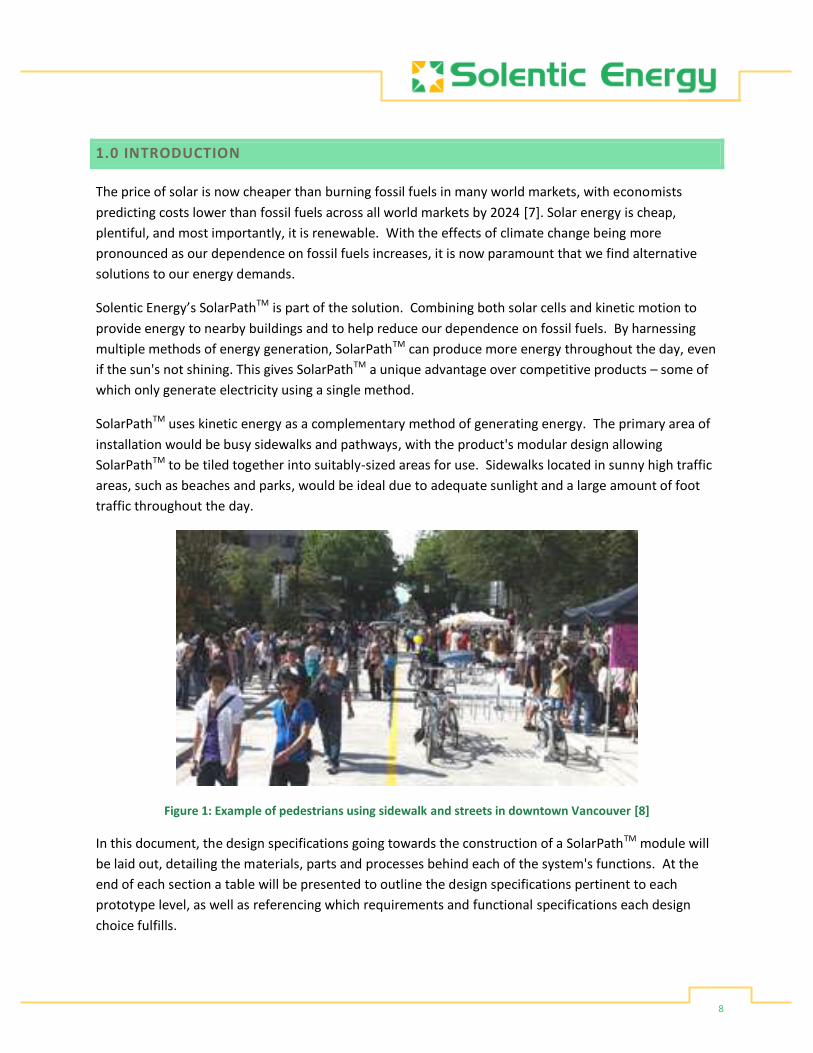
SolarPathTM uses kinetic energy as a complementary method of generating energy. The primary area of
installation would be busy sidewalks and pathways, with the product's modular design allowing
SolarPathTM to be tiled together into suitably-sized areas for use. Sidewalks located in sunny high traffic
areas, such as beaches and parks, would be ideal due to adequate sunlight and a large amount of foot
traffic throughout the day.
Figure 1: Example of pedestrians using sidewalk and streets in downtown Vancouver [8]
In this document, the design specifications going towards the construction of a SolarPathTM module will
be laid out, detailing the materials, parts and processes behind each of the system's functions. At the
end of each section a table will be presented to outline the design specifications pertinent to each
prototype level, as well as referencing which requirements and functional specifications each design
choice fulfills.

9
1.1 SCOPE
This document will cover the design specifications that need to be met in order for the successful
completion of Solentic Energy’s SolarPathTM. The requirements for the physical and electrical aspects of
each subsystem will be provided, with materials and devices selected based upon the functional and
requirement specifications for SolarPathTM. Considerations for product function and safe usage will be
explained for each component, and will serve as guidelines for the final product's testing and operation.
1.2 INTENDED AUDIENCE
This requirements document is intended to be used by employees of Solentic Energy as a reference in
the design and construction of SolarPathTM. The mechanical and electrical engineers can use this
document to refer back to design requirements and testing specifications. The project managers can use
this document to view specified timelines, targeted completion dates and overall progress of the
SolarPathTM project.

10
2.0 SYSTEM OVERVIEW
2.1 TOP LEVEL DESIGN
SolarPathTM consists of two integrated subsystems to simultaneously provide a walking surface for
pedestrians and energy generation. These two subsystems include one that captures solar energy and
another that captures the kinetic energy from pedestrians’ footsteps. The walkable surfaces of
individual tiles will be seamlessly linked together and provide charge for an external battery source.
The following two figures conceptualize how the completed tile design will appear from the top and
side-profile perspectives, respectively. Only the corner springs were maintained in order to better show
the internals of the product; the full product design includes eight springs at both the corners and edge
centers for stability. Visible are fundamental components from both the solar and kinetic energy
subsystems; the transparent protective surface, the solar panel, springs and generator, magnetic
connection contacts, and the chassis for the upper and lower halves of the system. The support springs
and safety stopping pillar heights are exaggerated to better show inner details.
Figure 2: SolarPathTM system diagram top view, detailing upper solar subsystem spring-supported structure

11
Figure 3: SolarPathTM system diagram side view, detailing the kinetic subsystem components, circuitry housing,
motor and gear systems, as well as additional support structure detail
For the electrical output of the system, SolarPathTM is designed to be interconnected via a system of rails
placed after installation of the tile units, in order to connect their various outputs into a single, unified
outlet for battery bank charging. The tiles will be installed such that they physically interconnect on any
of their four sides, while electrically each tie will have a dedicated positive and negative output linking
them in parallel with one another. The full SolarPathTM system setup, including the output rails, is shown
conceptually in the following figure (a top-down view with the upper solar layer removed for better
visibility);
Figure 4: Full SolarPathTM system setup, showing the tiles placed in a grid pattern interlaced with positive and
negative output rails

12
A conceptual cross-sectional view of the tile is provided below, detailing the view looking inwards at the
negative side of the tile, showing the negative outputs and rails alongside the physical components;
Figure 5: Conceptual cross-sectional view of tile, detailing negative electrical outputs alongside the physical
structure
The following flowchart illustrates the process of the solar energy and kinetic energy harnessing
subsystems, working in parallel and independently of one another, as well as a high-level concept of the
subsystem and overall SolarPathTM modularity, demonstrating how multiple systems will be
interconnected to charge an external battery bank.
Figure 6: High-level flowchart illustrating energy flow through subsystems and overall module connections

13
2.2 PROTOTYPES
Our development process will include four prototypes: Proof-of-Concept, Alpha, Beta, and Gamma,
constructed over staggered stages. This will allow for the gradual integration of features and step-by-
step testing of the SolarPathTM system, allowing for any necessary refinements or changes to the design
in order to ensure highest quality product performance. These stages, their projected completion date,
overall implemented features and testing focus are all tabulated below;
Table 1: Prototyping schedule, dates, features and testing
Prototype Completion Date Implemented Features Testing
Proof-of Concept April 10, 2017 Simple chassis (wood)
Solar energy generation
Kinetic energy generation
Charging a simple battery
Electrical testing, charging capacity and measurements
Alpha May 30, 2017 Construct metal chassis
Attach protective covering
Durability testing, repeated walking
Weight capacity
Beta June 30, 2017 Module connectivity - linking two tiles physically and electrically
Connectivity testing, electrical flow
Continued durability testing
Weatherproofing test, water
Gamma August 8, 2017 Final chassis construction
Final weatherproofing
Circuit finalization and weatherproofing
Weatherproofing test, water resistance
Similar tables will be presented throughout the document, further detailing each design choice's
implementation through each prototype stage alongside requirement and functionality criteria
fulfillment, referencing the numbers found in our Requirements and Functional Specifications
document.

14
3.0 HARDWARE DESIGN
The hardware components and design of SolarPathTM refer to all of the components and processes
which ensure the physical integrity of the product. As its intended use is for an outdoor pathway, the
system must be constructed to endure temperature extremes, weather conditions, and continued
physical duress from pedestrian traffic. According to the requirements and functional specifications,
SolarPath'sTM intended operational conditions are stated in Table 2 below;
Table 2: Values for operational ranges and physical properties of system
Operational Temperature: -10°C to 80°C (14°F to 176°F)
Weight Capacity: 181 kg (400 lb)
Estimated Life Cycle: Approx. 10 years
Dimensions: Approx. 12 cm x 60 cm x 60 cm (1'x2'x2')
These ranges were selected after analysis of solar panel temperature efficiency [9] [10] [11] [12] [13]
[14], average yearly weather patterns in Vancouver, BC [15], average weight of a person and a
wheelchair in North America [16] [17], the lifespan of a solar panel along with estimated mechanical
wear under pedestrian traffic [18] [19] and the standard size for a North American sidewalk tile [20]. For
detailed derivations and analysis, please refer to the Requirements and Functional Specifications
document.
3.1 UPPER SOLAR LAYER
The components of SolarPath'sTM solar energy subsystem include the protective cover and gasket, the
solar panel, and the overall chassis to house the panel and hold the transparent surface in place,
highlighted in the conceptual cross-section diagram below;
Figure 7: Conceptual cross-sectional diagram, highlighting the physical components of the upper solar energy
subsystem

15
For the subsystem to meet the operational requirements, the selected materials are a monocrystalline
silicone solar panel, glass sheet for the protective cover, silicon foam for the sealing gasket, and
galvanized steel for the chassis.
3.1.1 SOLAR PANEL
The solar panel selected for SolarPathTM, as well as its physical properties, are shown in Figure 8 and
Table 3 below;
Figure 8: 55.5 cm x 53.5 cm x 0.3cm, 12V, 50W semi-flexible monocrystalline solar panel [21]
Table 3: Physical properties of solar panel [21]
Material Monocrystalline silicon Dimensions 55.5 cm x 53.5 cm x 0.3cm (22" x 22" x 0.12") Operational temperature -40°C to +85°C Cell efficiency 22% Lifespan 25 years Weight ~100 g (0.22 lb) Other Waterproof, semi-flexible
As can be seen, the dimensions and operational temperature match those required in SolarPath'sTM
operational specifications of Table 2, with the waterproof nature meaning that the panel itself is also
protected from weather conditions should the protective cover or gasket sealant fail during operation.
In addition, it is very thin, lightweight, and semi-flexible, so that the panel itself does not put the lower
system under additional duress from its own mass, thickness, or rigidity.

16
The choice of monocrystalline silicon was made due to the high-quality of the material, as they are
single-ingot high-grade silicon crystals of the highest purity. This leads to the highest efficiency of all
solar panels (15-20%), very space-efficient systems, the longest lifespan (25 years), and the best low-
light performance of solar panels while maintaining high performances even in high-temperature
environments, allowing the highest energy output during the product's operation. [22]
The outline for the solar panel implementation across each prototype is tabulated below;
Table 4: Solar panel implementation plan and criteria
Prototype Features implemented Requirement/functionality fulfilled
Proof-of-Concept 12V, 50W semi-flexible monocrystalline solar panel installed into system
[SR-1 A] [SR-7 B] [SR-9-10 B] [SR-12 B] [SR-25 A] [SR-27 C]
[PD-28 A] [PD-31 A] [PD-31-34 B]
[ES-43-53 B]
Alpha
Beta
Gamma
3.1.2 GLASS SHEET
For a solar panel to function optimally, it requires a response of about 1 μm wavelength under glass;
Graph 1: Spectral response of ideal and experimental solar cells to varying wavelengths of light [23]
Therefore, a transparent material of comparable refractive index is required. For SolarPathTM, the
surface must also be able to withstand constant walking pressure and abrasion. Two options were

17
compared in regards to these criteria; tempered glass and polycarbonate sheets, both of which are
transparent mediums which have high impact resistance and strength. Some key properties are
presented in Table 5 below;
Table 5: Comparison of various physical properties of toughened (tempered) glass and polycarbonate [24] [25]
Toughened (Tempered) Glass
Polycarbonate
Refractive index 1.50 [23] 1.52 [26]
Light transmission
80-90% Max 88% (yellows under UV light) [27]
Density 2.4 g/cm3 1.2–1.4 g/cm3
Impact/pressure resistance
Minimum 4 times that of glass
65 MPa (9,400 psi) [28]
250 times that of glass [29]
35 kJ/m2 [30]
HDT (Heat deflection temperature)
N/A 130 to 140 °C (270 to 280 °F) [31]
Maximum strength to weight ratio
75 kN-m/kg 110 kN-m/kg
Flexibility Very low High
Weather resistance All (wind, rain, snow, temperature extremes) [32]
All (wind, rain, snow, temperature extremes) [33]
Chemical resistance Resistant to acids and alkali [34]
Resistant to gasoline and acids [29], very susceptible to alkali and solvents [33]
Surface quality More scratch resistant than glass [35]
Scratches and mars readily, cannot be restored with polishing [29] [30] [33]
Polycarbonate is one of the strongest and most weather-resistant plastic construction materials in the
general market, with its high strength for its light weight and good thermal resistance being its main
draws [29]. However, its key downsides of UV yellowing, flexibility and ease of surface marring make it
unsuitable for use as SolarPath'sTM top protective surface, which requires a sturdy and clear material
throughout its lifespan. [29] [30] [33] In addition, the manufacture of polycarbonate is very hazardous
to workers and not environmentally sound, using very high temperatures, phosgene, and chlorine,
which goes against Solentic Energy's standards and practices. [33]

18
Tempered glass maintains the clarity, weather and chemical resistance of regular clear glass, while also
becoming strengthened against impact, no longer breaking under stress until above 65 MPa or 9400 psi.
[35] In comparison, the capacity for a system used to measure the pressure for cars and trucks driving
overtop is 4.1 MPa or 600 psi, meaning that the glass could potentially withstand automotive traffic if
used alone. [36] Additionally, in order to make a suitable walkway, the glass can be treated with anti-
slip surfaces; small dots can be sand-blasted across the glass to provide traction without sacrificing a
large portion of the surface clarity. [37]
The outline for the protective cover implementation across each prototype is tabulated below;
Table 6: Protective cover implementation plan and criteria
Prototype Features implemented Requirement/functionality fulfilled
Proof-of-concept Basic removable wooden cover for compression testing
[SR-2 A] [SR-8 A]
Alpha Glass cover obtained [SR-7 B] [SR-10-12 A] [SR-22-23 A] [SR-25-27 A]
[ES-48-53 B]
Beta
Gamma
3.1.3 SOLAR SUPPORT STRUCTURE - SILICON FOAM AND GALVANIZED STEEL
To house the solar energy subsystem, the structure must be made to be fully exposed to weather
conditions and temperature extremes, as well as be able to continue to support the weight of
pedestrians.
In order to ensure the weatherproofing of the solar panel chamber itself, a thin gasket of silicon foam
will be placed between the glass and the chassis housing to seal out wind and water. An image and
some properties of closed-cell silicon foam are shown below;
Figure 9: Some examples of silicon foam gaskets [38]

19
Table 7: Physical properties of general closed-cell silicon foam [38] [39] [40]
Temperature range -67°F to 392°F (-55°C to 200°C) Physical properties Elastomeric, excellent compression set resistance,
variable thickness and firmness for different applications
Sealant properties Water and dust sealing Environmental resistance Oxygen, ozone, and UV light resistant Other resistance Thermal, chemical, electrical and aging resistant
With its versatile physical properties, ensuring the foam can be tailored to the correct size and thickness
required, along with its superior environmental resilience, silicon foam is an excellent fit to
weatherproof all exposed sections of SolarPathTM.
For the chassis material itself, the body must be constructed of a durable and non-corrosive material
that can be used in outdoor construction. The material to fulfill these requirements was selected to be
galvanized steel, image and properties (compared against aluminum and stainless steel) are shown
below;
Figure 10: Sheet of galvanized steel [41]
Table 8: Comparison of properties of aluminum, stainless steel, and galvanized steel [42] [43]
Aluminum Stainless steel Galvanized steel
Cost Lowest Highest Medium
Strength/Malleability High malleability High strength High strength
Corrosion resistance Absolute (never corrodes)
Medium (corrodes in extreme weather and stress conditions) [44]
High (corrodes only after decades of environmental use) [45]
Density [46] 2712 kg/m3 7480 - 8000 kg/m3 7850 kg/m3
Thermal conductivity [47] 118 BTU/(hr·ft⋅°F) 17 BTU/(hr·ft⋅°F) 17 BTU/(hr·ft⋅°F)

20
Though aluminum is the most corrosion-resistant, its low density leads to high malleability and easy
heat transfer, which will potentially lead to the product warping and overheating when under constant
stress and sunlight. Steel is the stronger metal, but requires treatment to prevent corrosion. While
stainless steel resists corrosion, it is not meant for constant use under extreme weather conditions,
whereas galvanized steel, used commonly in construction, is made to withstand such conditions for
many years, averaging up to 70 years in damp environments. [44]
The outline for the solar support structure implementation across each prototype is tabulated below;
Table 9: Solar support structure implementation plan and criteria
Prototype Features implemented Requirement/functionality fulfilled
Proof-of-concept Basic wooden chassis to house solar panel
[SR-2 A] [SR-8 A] [SR-12 B]
Alpha First design of metal chassis and initial gasket installed for glass panel
[SR-7 B] [SR-16 B]
Beta
Gamma Final chassis design and final gasket implemented to seal solar panel system
[SR-9-10 B] [SR-21-27 B]
[ES-44 C] [ES-48-53 B]
3.2 LOWER KINETIC LAYER
The components of SolarPath'sTM kinetic energy subsystem include the motor and lever system, the
support springs and safety stoppers, as well as the lower casing for ground installation. These features
are highlighted in the conceptual cross-section diagram below;
Figure 11: Conceptual cross-sectional diagram, highlighting the physical components of the lower kinetic energy
subsystem

21
For the subsystem to meet the operational requirements, the selected materials are a Wind DC
generator dynamo, heavy-duty die springs, CPVC tubes, galvanized steel, post spikes, steel strips and
bolts, and silicon foam for weatherproofing inter-component casings.
3.2.1 MOTORS AND LEVER SYSTEM
In order to capture the kinetic energy as electric energy, the system requires a small motor which can fit
beneath the upper solar subsystem layer while still allowing for room for circuitry and a system for
turning the motor itself. The following DC motor was selected, its dimensions listed in the figure and
table below;
Figure 12: Dimensions of the wind-driven DC generator dynamo, given in mm [48]
Table 10: Physical properties of the wind-driven DC generator dynamo [48]
Length: 130 mm Motor diameter: 35 mm Shaft length: 22 mm Shaft diameter: 8 mm Material: Plastic, iron Weight: 400g
The motor itself will be positioned laterally so that the shaft will be parallel to the ground, allowing
roughly 8-10 cm of space beneath the tile so that the top layer can displace up to 2 cm without hitting
the implement. It will be mounted by bolting into a weatherproof container at the floor of the chassis,
slightly elevated to avoid any collected water that could arise. The shaft will be extended out of the
container in order to allow rotation and the non-rotational base sealed with silicon foam as described in
3.1.3 Solar Support structure - Silicon Foam and Galvanized Steel.
22
An example of the weatherproofing cover for the shaft side of the motor is shown below;
Figure 13: Weatherproof 4"x2.75"x2" outlet box [49]
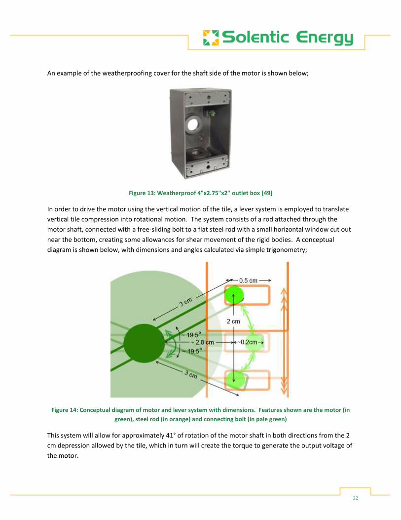
In order to drive the motor using the vertical motion of the tile, a lever system is employed to translate
vertical tile compression into rotational motion. The system consists of a rod attached through the
motor shaft, connected with a free-sliding bolt to a flat steel rod with a small horizontal window cut out
near the bottom, creating some allowances for shear movement of the rigid bodies. A conceptual
diagram is shown below, with dimensions and angles calculated via simple trigonometry;
Figure 14: Conceptual diagram of motor and lever system with dimensions. Features shown are the motor (in
green), steel rod (in orange) and connecting bolt (in pale green)
This system will allow for approximately 41° of rotation of the motor shaft in both directions from the 2
cm depression allowed by the tile, which in turn will create the torque to generate the output voltage of
the motor.

23
The outline for the motor and lever system implementation across each prototype is tabulated below;
Table 11: Motor and lever system implementation plan and criteria
Prototype Features implemented Requirement/functionality fulfilled
Proof-of-concept DC motor installed with prototype lever system
[SR-1 A] [SR-16 B]
[PD-28 A] [PD-35-37 A] [PD-39 A]
Alpha Lever system improved and finalized, preliminary weatherproof container created for motor housing
[SR-20 A] [PD-38 B]
Beta
Gamma Final motor housing and lever system installation
[SR-9-10 B] [SR-21 B] [SR-24-27 B]
[PD-30 B] [ES-43-46 A] [ES-48-53 B]
3.2.2 SPRINGS AND SAFETY SUPPORTS
Due to the motor requiring vertical movement to generate power, the springs were selected to be able
to compress 1-2 cm even with the minimum load of a single, average-massed person (80.7 kg or 177.913
lb) [16]. In mechanics, two or more springs are said to be in series when they are connected end-to-end,
and in parallel when they are connected side-by-side; in both cases, so as to act as a single spring. In the
product's system, eight springs are to be used to support a single structure, thus reflecting the 'parallel'
spring configuration as shown below;
Figure 15: Springs in parallel configuration [50]
The relevant formulas for the parallel-spring situation, as well as its derivation, are shown below;
Figure 16: Spring and force equations for parallel configuration [50]

24
Figure 17: Derivation of the equivalent spring constant for parallel configuration [50]
Hooke’s Law is used to relate the force acting on a spring with its displacement from equilibrium and the
inherent spring constant k:
Figure 18: Hooke's Law for force, spring constant, distance from equilibrium and equilibrium position [50]
We desire the spring to be at 10 cm (0.1 m) length when depressed from force of platform and
pedestrian and have set dx from a footstep to be 2 cm (0.02 m). The spring should therefore be 12 cm
(0.12 m) long. This is equivalent to 4.72 inches.
The force from a walker/runner is approximately 1000-2000 N (based on an average of 70-80 kg mass).
Using Hooke's Law and the parallel spring theorem (treating all eight as a single spring), these
constraints dictate a Keq of 50,000-100,000 N/m or kg/s2. [51] [52]

25
Divided by 8 identical springs - K1, K2, K3, K4, K5, K6, K7, K8 = 6,250-12,500 N/m or kg/s2. This is
equivalent to approximately 35.69-71.38 lb/inch.
Using this range of K constants, a spring was selected to lie within this range and have a reasonably wide
diameter versus height, shown below;
Figure 19: 1/2" OD x 9/32" ID x 3-1/2" OAL Red Medium-Heavy Duty Die Spring [53]
Table 12: Physical properties of the Raymond® Heavy-Duty Die Spring [53]
Inner Diameter 9/32"
Length 3-1/2" Material Chrome Silicon Outer Diameter 1/2" Rating 4.0 lb per 1/10" Style Medium Heavy Duty Type Raymond® Die Spring Product Weight 0.046 lbs
This spring has the proper K-value with the widest dimeter to the shortest length in order to allow for
better stability. As well, the chrome silicon allows for a maximum temperature tolerance of 245°C. [54]
For the safety supports, CPVC tubes were selected, due to sharing PVC's strong and rigid structure and
resistance to most acids and bases, but also having a higher operating temperature of 82°C degrees as
opposed to 60°C. [55] They also come in a wide variety of diameters and thicknesses and can be easily
cut and worked to the required height. [56] One example with PVC cutters and a ½" pipe are shown
below;
Figure 20: CPVC/PVC tubing cutter and 1/2" CPVC tubing [56]

26
The outline for the springs and safety support system implementation across each prototype is
tabulated below;
Table 13: Spring and safety support implementation plan and criteria
Prototype Features implemented Requirement/functionality fulfilled
Proof-of-concept Springs temporarily mounted in prototype chassis for weight and compression testing, temporary stoppers made of either plastic or wood
[SR-8 A] [SR-13-16 B]
[PD-28 A]
Alpha Final springs and safety stoppers installed into new metal chassis
[SR-25 A] [PD-38 B] [ES-46 A] [ES-48-53 B]
Beta
Gamma
3.2.3 LOWER SUPPORT STRUCTURE
As with the upper chassis, the lower support structure will need to be of a weather-durable material
that is non-corrosive, sturdy and with a long lifespan. These criteria are nearly identical to those of the
upper chassis; therefore galvanized steel was selected as the chassis material, based upon the analysis
performed in 3.1.3 Solar Support structure - Silicon Foam and Galvanized Steel.
For physical interconnection between tiles, the chassis is designed to be able to bolted together
adjacent tiles on any of the four edges via galvanized steel strips, bolts and screws. An example of a
two-by-two interconnection of tiles is shown below, simplified to show only the lower chassis, spring,
and connection placements;
Figure 21: Conceptual diagram of physical connections between tiles, demonstrated on a 2x2 tile layout

27
The two bolted sections along each tile's edge will help ensure that the tiles are secure against one-
another, and solely bolting the bottom chassis together ensures that each module's upper chassis will be
able to compress freely and independently of one another.
To fully secure the system, the modules will be mounted into the ground via four post spikes, attached
to the bottom of each corner of the lower chassis. Some examples of post spikes are shown below;
Figure 22: Two examples of type G post spikes with plates [57]
These spikes are zinc-plated to prevent rust and corrosion, have long lifespans suitable for use with
either wood or metal ground installations, extremely durable, and environmentally friendly. [57] After
they are attached to the chassis, each SolarPathTM tile can then simply be pressed firmly into the ground
to secure, and can be moved or relocated if needed as well, making installation simple and easy for
customer use.
The outline for the lower support structure implementation across each prototype is tabulated below;
Table 14: Lower support structure implementation plan and criteria
Prototype Features implemented Requirement/functionality fulfilled
Proof-of-concept Simple chassis made of wood, no interconnects or spikes
[SR-2 A] [SR-12 B]
Alpha Chassis constructed out of metal
[SR-7-10 B] [SR-16 B]
Beta Connection holes drilled for steel bolts and plates
[SR-4 A] [SR-17-18 A]
Gamma Post spikes attached to bottom of chassis for ground installation
[SR-5 A] [SR-19 B] [SR-25-27 B]
[ES-44 C] [ES-48-53 B]

28
4.0 ELECTRICAL DESIGN
SolarPathTM is designed to provide charge for a 12 V battery bank, based upon the typical capacity of a
lead-acid battery. A lead-acid battery was selected as the target charging load, as unlike lithium-ion
batteries it can withstand continuous charging and discharging from zero capacity. [58] In order to
accomplish this requirement, SolarPathTM is designed with two energy subsystems working in parallel in
each tile module, a solar and a kinetic energy system, and overall parallelization of a network of
individual tile modules as well, as shown in Figure 4 and Figure 6 under 2.1 Top Level Design. The
electrical components that will be described in this section are highlighted in the conceptual cross-
sectional diagram below;
Figure 23: Conceptual cross-sectional diagram with electrical components highlighted (negative outputs shown,
positive outputs on other side of tile)
These specifications will present three main groups of the electrical components; the solar output, the
kinetic output, and the interconnection rails and main output.

29
4.1 SOLAR OUTPUT
The goal of the solar subsystem is to provide a minimum of 12 V in parallel with the kinetic system. The
electrical properties of the selected solar panel from
3.1.1 Solar panel are tabulated below;
Table 15: Electrical properties of solar panel [21]
Voltage 12 V Power 50 W Current 4.2 A Cell efficiency 22% STC 1000 W/m 2h MC4 Connecting Line 96 cm MC4 Connector 2 pcs
As can be seen, this solar panel meets the requirements for a 12 V output, and will do so with the
parameters listed above. The output of each solar panel is to be sent via MC4 connector and line,
shown below;
Figure 24: MC4 connectors for PV systems, male (right) and female (left) [59]
These connecting cables are UV and weather-protected with a plug-and-socket design, in order to lock
firmly and seal out water damage. [59] A positive and negative MC4 output is equipped with each solar
panel, which will be lead down to the circuit box on the undercarriage of the upper chassis and attached
to output leads for the interconnection rails.
The outline for the solar subsystem electrical implementation across each prototype is tabulated below;

30
Table 16: Solar subsystem electrical implementation plan and criteria
Prototype Features implemented Requirement/functionality fulfilled
Proof-of-concept Solar panel outputs directly to charge controller
[SR-1 A] [SR-3 A] [SR-7 B]
[PD-28-34 A]
Alpha
Beta Solar panel output connected through circuit box and connects to output rail
[SR-4 A] [SR-9 B] [SR-20-21 B] [SR 25-28 C]
[ES-43-53 A]
Gamma
4.2 KINETIC OUTPUT
The electrical properties of the selected DC wind-powered motor (selected in 3.2.1 Motors and Lever
System) are shown below;
Table 17: Electrical properties of wind-powered DC motor [48]
Motor output voltage: 5V-24V Maximum output current exceeds: 1500 mA Maximum load voltage: 40 V Maximum load power: 20 watts
Although the maximum output voltage of the motor reaches 24 V, this is dependent on the speed of
rotation of the motor shaft. With the vertical movement of the tile limited to 2 cm and dampened
slightly by the springs, the motor's output will be at the lower range (5 V), found via experimental
testing. In addition, as the tile compresses and returns to its original height, the motor will be
generating voltage in alternating directions, due to the internal armature being driven in opposing
directions and inducing opposing currents from the forwards and backwards rotation. [60]
In order to maintain a DC output of 12 V from the selected motor, an additional circuit is required to first
convert the AC output to DC, amplify the output voltage to a minimum of 12 V, as well as prevent back
charging of the motor. The parts required to perform these functions are a bridge rectifier, followed by
a DC to DC step-up module, and finally a diode rectifier.

31
4.2.1 BRIDGE RECTIFIER
A bridge rectifier, or full wave diode bridge rectifier, is comprised of four diodes placed in a loop, each of
which acting as a switch prior to only allow positive voltage to pass. [5] [61] An illustration of the setup
and the positive and negative half-cycle current flows are shown in the following figures;
Figure 25: Full wave diode bridge rectifier, positive half-cycle [61]
Figure 26: Full wave diode bridge rectifier, negative half-cycle [61]
This configuration often includes a smoothing capacitor in parallel with the output, which aids in
reducing the amount of "ripple" (voltage drop) the DC load experiences between the positive and
negative phases of the charging source. [61] The final configuration, along with the resultant output
waveform, is shown below;
Figure 27: Full wave diode bridge rectifier with smoothing capacitor and resultant output waveform [61]

32
The RS604 bridge rectifier, selected to fulfill the circuit requirements, is shown in Figure 28, along with
its maximum ratings and electrical characteristics in Figure 29;
Figure 28: RS604 bridge rectifier [62]
Figure 29: Maximum ratings and electrical characteristics for the RS604 bridge rectifier [63]
This rectifier is rated up to 400V with an operational temperature range well within those of the
SolarPathTM system, making it a good fit for the product's circuit.
4.2.2 DC-DC STEP-UP CONVERTER MODULE
The LM2587 step-up DC-DC converter module is shown in Figure 30, with its specifications listed in Table
18 below;
Figure 30: LM2587 step-up DC-DC converter module [64]

33
Table 18: LM2587 specifications [64]
Nature of the module: Non-isolated boost (Boost) Rectification: Non-synchronous rectification Input voltage: 3V - 30V Output voltage: 4V - 35V Output current: 5A (maximum), load current: 15mA Transfer efficiency: 92% (maximum) Switching frequency: 100KHz Output ripple: 50mV (maximum) Load regulation: ±0.5% Voltage regulation: ±0.5% Operating temperature: -40°C to +85°C Dimension: 48 x 23 x 14mm (L x W x H) Power: 15W (no radiator), 20W (with radiator)
This model of step-up converter allows for input voltages as small as 3V to be amplified up to 35V, and is
easily tunable to meet SolarPath'sTM specifications, with some typical outputs shown below;
Table 19: Sample of typical outputs for LM2587
Input Output
5V 12V / 1.2A 5V 24V / 0.6A 7.4V 12V / 2A 7.4V 19V / 1.2A 7.4V 24V / 0.9A 12V 19V / 2A 12V 24V / 1.5A
The LM2587 was also selected for the high maximum transfer efficient of 92%, its minimal output ripple
as low as 50 mV, as well as small size and low power for minimal heat production, allowing it to be safely
and readily integrated into SolarPath'sTM electrical system.
4.2.3 DIODE RECTIFIER
A diode rectifier's purpose is to restrict current flow in one direction only. [5] In the case of our product,
with the outputs all linked in parallel and the motors producing only sporadic output, a rectifier must be
put in place to prevent the solar panel or adjacent tile outputs from running the motor. The 1N5402
diode rectifier is shown along with its electrical properties in Figure 31 and Table 20 below;

34
Figure 31: 1N5402 diode rectifier [65]
Table 20: Specifications of 1N5402 diode rectifier [66]
Voltage - Forward (vf) (max) @ If 1.2V @ 3A Current - Average Rectified (io) 3A Diode Type Standard Capacitance @ Vr, F 30pF @ 4V, 1MHz Package / Case DO-201AD, Axial Configuration Single Forward Voltage Drop 1.2 V Max Surge Current 200 A Power Dissipation 6.25 W Maximum Operating Temperature + 150 C Lead Free Status / RoHS Status Lead free / RoHS Compliant Voltage - Dc Reverse (vr) (max) 200V Current - Reverse Leakage @ Vr 5µA @ 200V Speed Standard Recovery >500ns, > 200mA (Io) Mounting Type Through Hole Product Standard Recovery Rectifier Reverse Voltage 200 V Forward Continuous Current 3 A @ Ta=75C Reverse Current Ir 5 uA Mounting Style Through Hole Minimum Operating Temperature - 55 C Reverse Recovery Time (trr) -
This diode allows outputs of 1.2V/3A and above to pass through, while preventing any backflow up to
200V, while also lying within the product's operational temperature range and being lead free and RoHS
compliant, making it a good choice to integrate with our product.
4.2.4 CIRCUIT BOX
The final kinetic output circuit will be housed within a circuit box attached to the undercarriage of the
upper solar energy chassis. This is designed to keep the electrical components away from any potential
water collection on the bottom of the lower chassis, while also allowing the box to be vented along its
sides for better heat dissipation. A temporary circuit box with the assembled kinetic output circuit is
shown in the figures below;

35
Figure 32: Kinetic output circuit, showing the diode (left), DC-DC step-up module (right) and bridge rectifier leads
(top), resting in a temporary circuit box
Figure 33: Closed temporary circuit box with vents along bottom of box and output leads out of sides
In the final model of SolarPathTM , the vents will be moved from the bottom to the sides of the box
between the leads, due to the bottom being the most likely part to touch any water collected in the
system. The input leads from the motor and the output leads to the intermediary rails will be
waterproofed with silicon foam, while any additional heatsinks required may be attached to the bottom
surface for further heat dissipation.

36
The outline for the kinetic subsystem electrical implementation across each prototype is tabulated
below;
Table 21: Kinetic subsystem electrical implementation plan and criteria
Prototype Features implemented Requirement/functionality fulfilled
Proof-of-concept Motor and intermediary circuit implemented in temporary circuit box
[SR-1-3 A]
[PD-28-29 A] [PD-35-39 A]
Alpha Circuit box weatherproofed and attached to undercarriage of upper chassis
[SR-4 A] [SR-9 B]
[PD-31 A]
Beta Outputs of circuit box weatherproofed and connected to main output rail
[SR-20-21 B] [SR-25-27 C]
[PD-30 B] [ES-43-53 A]
Gamma
4.3 TILE INTERCONNECTION RAILS AND MAIN OUTPUT
As shown in Figure 4 and Figure 6, the tiles will be electrically connected in parallel with one-another via
external output rails, carrying the positive and negative outputs along opposing sides of rows of tile
modules to a single output rail for battery bank charging. This parallel connection of the solar and
kinetic outputs, along with the outputs of neighbouring tiles, will allow for scalability of the overall
system; as more tiles are added to the pathway area, the output voltage will remain a consistent 12 V,
instead of becoming cumulative as it would with a series system connection (shown in Figure 34). [67]
Figure 34: Comparison of a simple series connection versus a simple parallel connection [67]

37
The rails themselves are copper wire enclosed in weatherproofed, colour-coded PVC pipes (red for
positive and blue for negative), fitted between the compression springs and safety stoppers along
opposite edges of each tile. Copper wiring was selected for its excellent electrical conductivity and
corrosion resistance, allowing high conduction along long rails even in outdoor environments. It is also
easily joined and ductile while maintaining its strength, as well as being non-magnetic and recyclable,
making it suitable to be used in the conduction rails in SolarPathTM sidewalks without worry of bending
issues or magnetic interference in its vicinity. [68]
Along the rail, there will be outlets equipped with MC4 connectors for the solar panel outputs, as well as
weatherproofed single-pin outlets for the kinetic system outputs, an example shown below;
Figure 35: Esky Mall weatherproofed electrical wire connection plug components; one-way male and female
housing (top), cable seals (bottom left) and male and female terminals (bottom right) [69]
Currently, the rails are meant to be sized prior to installation of the SolarPathTM system, with each rail's
length determined by the number of tiles to be placed and connected in a given area, but future designs
will allow for modular rail portions for each tile that can link together like a segmented pipe.
The outline for the tile interconnection and main output rail implementation across each prototype is
tabulated below;
Table 22: Tile interconnection and main output rail implementation plan and criteria
Prototype Features implemented Requirement/functionality fulfilled
Proof-of-concept Basic outputs from solar and kinetic directly to charge controller and battery
[SR-1 A] [SR-3 A]
[PD-28 A]
Alpha
Beta Interconnection and main output rails installed into system
[SR-4 A] [SR-9 B] [SR-20-12 B] [SR-25-27 C]
[PD-29-31 A] [PD-40-42 A]
[ES-43-53 A]
Gamma

38
5.0 SUSTAINABILITY AND SAFETY
At Solentic Energy, we are dedicated to creating a product which produces a sustainable source of
power. Therefore, we also endeavor to work towards making SolarPathTM itself a sustainable and safe
device throughout the entirety of its lifespan and beyond.
Our ideal vision for SolarPath'sTM lifecycle would be that of the cradle to cradle design, wherein every
stage of the product's life would be developed to be as environmentally sound as possible, making use
of recycled materials, responsible and renewable manufacturing methods, and be ultimately recyclable
with minimal waste. [70] To approach this ideal, we will work through multiple design stages to
construct with as many recycled materials as possible, while also developing a sound structure with a
long lifespan in order to maximize product use and minimize part replacement.
As stated under our Requirements and Functional Specifications - Engineering Standards, our
requirements for SolarPathTM include following the guidelines for designing for sustainability in CSA's
Z762-95 [71] as well as life cycle assessment in CAN/CSA-ISO 14040-06 [72], driving our development
stages to focus on sustainability. The estimated lifespan for a completed product will be approximately
10 years, in order to maximize material use and minimize repair costs and waste from over-frequent
replacement, as well as being reparable after installation. The kinetic subsystem were also streamlined,
from an original plan of four to eight motors in series, to a single motor and intermediary circuit for 12V
output, reducing the amount of both mechanical and electrical components per tile, simplifying repairs
and maintenance. This will allow for reuse of the solar subsystem between expended modules, and aid
in minimizing waste from motor repairs and replacements. In addition, for the product to be deemed
acceptable, we require all materials used to be lead-free and RoHS compliant [73], allowing long-term
use in outdoor conditions without polluting the installation area via harmful or corrosive matter. Finally,
the ultimate disposal of SolarPathTM after the end of its lifespan will be compliant to the guidelines
outlined in CSA's SPE-890-15, detailing best practices for managing end-of-life materials. [74]
Due to its intended use as a public pedestrian pathway, we demand additional requirements for
SolarPathTM to be deemed safe and reliable for all users. By complying with the CAN/CSA and IEE
guidelines for electrical installations, we ensure that our product's electronic components will remain
operational and secure under all weather conditions to which it shall be subjected. All electrical
components are designed to either be stored away from weather conditions such as wind or rain, or
sealed with weatherproof materials such as silicon foam. In addition, the main circuitry of the system
will be housed away from water and vented at the sides to aid in heat dissipation.
In order to assure the safety of pedestrians, we have added in the stipulations that the walking surface
be a secure, non-slip and sturdy platform. Tempered glass was ultimately chosen despite potential for
obstructive spider-web patterns when cracked, sacrificing some usability if the product in order to
reduce risk of large glass shards upon breaking, which would compromise user safety. Compression of
the product is also minimized to no more than 2 cm, with permanent safety stoppers to prevent any

39
further compression. This is to minimize any risks of balance-loss for pedestrians, or difficulty in passage
for wheelchairs and other wheeled devices on uneven surfaces, as well as the stoppers preventing
sudden, spontaneous compression should the springs happen to fail. As for safety regarding our
product's construction, we have outlined the need for materials that will not rust or corrode over long-
term, outdoor use, and which are free from hazardous substances that could pollute or cause harm to
either users or maintenance workers. This was brought into consideration for the choice in non-
corrosive alloys such as galvanized steel or copper, as well as electrical components being rated lead-
free and RoHS compliant for all modules.

40
6.0 CONCLUSION
Solentic Energy’s SolarPathTM is a product designed to discretely and unobtrusively generate energy from
renewable methods. It will be best applied in sunny and high foot traffic areas including sidewalks near
beaches, parks and campuses. Harvesting energy from busy sidewalks using solar a kinetic energy can be
used to power streetlights stored in batteries or sent straight to the grid. Fossil fuels are a problem since
it is an energy source that takes millions of years to produce while nuclear is very expensive and has
dangerous by products. We need a green energy and long lasting solution. Novel and renewable energy
products like SolarPathTM will help contribute to our much needed green energy future.
This document covered the system overview, prototype schedule, hardware and electrical design, and
safety standards for SolarPathTM. The UI interface and test plan documentation are also included in the
specification appendix.
Our project will consist of four prototypes: proof of concept, alpha, beta and gamma prototypes. Each
successive prototype will improve upon build quality by using more robust production-ready materials
including alloys and glass. The physical components of the system will be housed in two galvanized steel
chassis, an upper for the solar layer and a lower for the kinetic layer. For the solar panel layer, the
covering will be constructed of tempered glass sealed with silicon foam, with a 50W 12V
monocrystalline silicon solar panel to collect solar energy. The lower kinetic layer will house a wind-
driven DC generator dynamo in a weatherproof box at the bottom, while a lever system will attach to
the upper layer to drive its rotation. Heavy-duty die springs and CPVC pipes will support the structure
and control the compression, while bolts and steel panels will interconnect panels and post spike will
keep the tiles secured into the ground.
The electrical components, both within the tile (solar and kinetic systems) and between tiles will be
placed in parallel, linked with interconnecting output rails of copper wire with MC4 and weatherproof
single-pin outlets. The solar panel output is rated at 12V, and the output of the motor is raised to 12V
through a RS604 bridge rectifier, LM2587 step-up DC-DC converter module, and a 1N5402 diode rectifier
to prevent back charging.
Each component and design choice was selected in order to comply with CSA and IEEE guidelines for
sustainability and safety, ensuring a high quality and environmentally-sound product that is safe for all
users.

41
REFERENCES
[1] Frankfurt School-UNEP Centre, "Global Trends in Renewable Energy Investment 2016," 2016.
[Online]. Available: http://fs-unep-
centre.org/sites/default/files/publications/globaltrendsinrenewableenergyinvestment2016lowres
_0.pdf. [Accessed 13 March 2017].
[2] Solar-electric.com, "How to connect MC4 connectors and connection cables," Northern Arizona
Wind & Sun, 2017. [Online]. Available: https://www.solar-electric.com/how-to-use-mc4-
connectors-cables.html/. [Accessed 15 March 2017].
[3] National Renewable Energy Laboratory, "Solar Photovoltaic Technology Basics," US Departmenet
of Energy, [Online]. Available: https://www.nrel.gov/workingwithus/re-photovoltaics.html.
[Accessed 13 February 2017].
[4] Solar Direct, "How Solar Electric Technology Works," Solar Direct, 2016. [Online]. Available:
http://www.solardirect.com/pv/pvbasics/pvbasics.htm. [Accessed 13 February 2017].
[5] T. R. Kuphaldt, "Rectifier Circuits, Chapter 3 - Diodes and Rectifiers," EETech Media, LLC., 2001.
[Online]. Available: https://www.allaboutcircuits.com/textbook/semiconductors/chpt-3/rectifier-
circuits/. [Accessed 27 March 2017].
[6] SunPower Corporation, "Understanding Solar System Ratings," 2017. [Online]. Available:
https://us.sunpower.com/sites/sunpower/files/media-library/white-papers/wp-understanding-
solar-system-ratings.pdf. [Accessed 13 March 2017].
[7] M. Shankleman and M. Martin, "This Could Become the Cheapest Power on Earth,"
Bloomberg.com, 2017. [Online]. Available: https://www.bloomberg.com/news/articles/2017-01-
03/for-cheapestpower-on-earth-look-skyward-as-coal-falls-to-solar. [Accessed 30 January 2017].
[8] City of Vancouver, "Street and sidewalk use for business and activities," City of Vancouver, 2017.
[Online]. Available: http://vancouver.ca/streets-transportation/street-and-sidewalk-use-for-
business-and-activities.aspx. [Accessed 19 February 2017].

42
[9] D. Waco, "How Heat Affects Solar Panel Efficiency," CivicSolar Inc., 8 November 2011. [Online].
Available: https://www.civicsolar.com/support/installer/articles/how-heat-affects-solar-panel-
efficiency. [Accessed 12 February 2017].
[10] E. R. Messmer, "Solar Cell Efficiency vs. Module Power Output: Simulation of a Solar Cell in a CPV
Module," 6 March 2013. [Online]. Available: http://www.intechopen.com/books/solar-cells-
research-and-application-perspectives/solar-cell-efficiency-vs-module-power-output-simulation-
of-a-solar-cell-in-a-cpv-module. [Accessed 13 March 2017].
[11] Tindo Solar, "Temperature Coefficient," Tindo Solar, 2017. [Online]. Available:
http://www.tindosolar.com.au/learn-more/temperature-coefficient/. [Accessed 15 February
2017].
[12] Solar Power Beginner, "Solar Panel Temperature Coefficient:," Solar Power Beginner, 2015.
[Online]. Available: http://www.solarpowerbeginner.com/solar-panel-temperature-
coefficient.html. [Accessed 15 February 2017].
[13] D. L. King, J. A. Kratochvil and W. E. Boyson, "Temperature Coefficients for PV Modules and
Arrays: Measurement Methods, Difficulties, and Results," Sandia National Laboratories, 29
September 1999. [Online]. Available:
http://citeseerx.ist.psu.edu/viewdoc/download?doi=10.1.1.120.5868&rep=rep1&type=pdf.
[Accessed 15 February 2017].
[14] IdeaScale, "Solar Panels Efficiency in Non-optimal Temperature Conditions," IdeaScale, June 2014.
[Online]. Available: http://catalyst.energy.gov/a/dtd/Solar-Panels-Efficiency-in-Non-optimal-
Temperature-Conditions/55986-29324. [Accessed 13 February 2017].
[15] WeatherSpark, "Average Weather For Vancouver, British Columbia, Canada," Cedar Lake
Ventures, Inc, 2013. [Online]. Available: https://weatherspark.com/averages/28404/Vancouver-
British-Columbia-Canada. [Accessed 12 February 2017].
[16] S. C. Walpole, D. Prieto-Merino, P. Edwards, J. Cleland, G. Stevens and I. Roberts, "The weight of
nations: an estimation of adult human biomass," 18 June 2012. [Online]. Available:
https://www.biomedcentral.com/content/pdf/1471-2458-12-439.pd. [Accessed 13 March 2017].

43
[17] The Medical Supply Guide.com, "How much does an electric wheelchair weigh?," The Medical
Supply Guide.com, 2015. [Online]. Available:
http://www.themedsupplyguide.com/electric_wheelchairs/weigh/. [Accessed 13 March 2017].
[18] T. Lombardo, "What Is the Lifespan of a Solar Panel?," Engineering.com, 20 April 2014. [Online].
Available:
http://www.engineering.com/ElectronicsDesign/ElectronicsDesignArticles/ArticleID/7475/What-
Is-the-Lifespan-of-a-Solar-Panel.aspx. [Accessed 10 February 2017].
[19] City of Vancouver, "2013 Pedestrian Volume and Opinion Survey," City of Vancouver, 2013.
[Online]. Available: http://vancouver.ca/files/cov/report-2013-pedestrian-volume-opinion-
survey-summary.pdf. [Accessed 13 February 2017].
[20] Federal Highway Administration, "Designing Sidewalks and Trails for Access," US Department of
Transportation, 10 February 2014. [Online]. Available:
https://www.fhwa.dot.gov/environment/bicycle_pedestrian/publications/sidewalks/chap4a.cfm.
[Accessed 10 February 2017].
[21] Ebay, "Practical 12v 50w Sunpower Soft-Flexible Solar Panel Monocrystalline Tool," Ebay, March
2017. [Online]. Available: http://www.ebay.ca/itm/Practical-12v-50w-Sunpower-Soft-Flexible-
Solar-Panel-Monocrystalline-
Tool/291985384522?_trksid=p2047675.c100005.m1851&_trkparms=aid%3D222007%26algo%3D
SIC.MBE%26ao%3D1%26asc%3D20140620091118%26meid%3D53395f94d8df4a16ad9dcc29f9a4
780a%. [Accessed 9 March 2017].
[22] M. A. Maehlum, "Which Solar Panel Type is Best? Mono- vs. Polycrystalline vs. Thin Film," Energy
Informative, 18 May 2015. [Online]. Available: http://energyinformative.org/best-solar-panel-
monocrystalline-polycrystalline-thin-film/. [Accessed 13 March 2107].
[23] C. Honsberg and S. Bowden, "Spectral Response," Photovoltaic Education, 13 February 2017.
[Online]. Available: http://pveducation.org/pvcdrom/solar-cell-operation/spectral-response .
[Accessed 13 March 2017].
[24] MakeItFrom.com, "Toughened (Tempered) Soda-Lime Glass," MakeItFrom.com, 6 August 2016.
[Online]. Available: http://www.makeitfrom.com/material-properties/Toughened-Tempered-

44
Soda-Lime-Glass#Properties. [Accessed 13 March 2017].
[25] MakeItFrom.com, "Polycarbonate (PC)," MakeItFrom.com, 6 August 2016. [Online]. Available:
http://www.makeitfrom.com/material-properties/Polycarbonate-PC. [Accessed 13 March 2017].
[26] G. Heiting, "Polycarbonate vs. Trivex Eyeglass Lenses - Which Is Right for You?,"
AllAboutVision.com, May 2014. [Online]. Available:
http://www.allaboutvision.com/lenses/polycarb.htm. [Accessed 13 March 2017].
[27] Winter Gardenz Greenhouses, "Glass vs. Polycarbonate vs. Plastic Film," Winter Gardenz
Greenhouses, 2016. [Online]. Available: http://www.wintergardenz.co.nz/glass-vs-poly-vs-
film.html. [Accessed 13 March 2017].
[28] agmglassdesign, "Regular Glass vs Tempered Glass," Accurate Glass & Mirror, 19 August 2014.
[Online]. Available: http://agmglassdesign.com/regular-glass-vs-tempered-glass/. [Accessed 20
March 2017].
[29] The Plastic Person, "How Are Polycarbonate & Acrylic Different," The Plastic People, 1 June 2012.
[Online]. Available: http://blog.theplasticpeople.co.uk/2012/06/01/how-are-polycarbonate-
acrylic-different/. [Accessed 13 March 2017].
[30] Hydrosight, "Acrylic Vs. Polycarbonate: A Quantitative And Qualitative Comparison," Hydrosight,
26 May 2015. [Online]. Available: http://www.hydrosight.com/acrylic-vs-polycarbonate-a-
quantitative-and-qualitative-comparison/. [Accessed 13 March 2017].
[31] A&C Plastics, "Why Polycarbonate Sheet is a Better Investment Than Glass," A&C Plastics Inc.,
2017. [Online]. Available: http://www.acplasticsinc.com/informationcenter/r/polycarbonate-
sheet-is-a-better-investment-than-glass. [Accessed 13 March 2017].
[32] Klaasimeister, "Tempered glass," Klaasimeister, 2017. [Online]. Available:
http://www.klaasimeister.ee/index.php?page=164&. [Accessed 20 March 2017].
[33] DoItYourself - Roofing Materials, "Pros and Cons of Polycarbonate Panels," DoItYourself.com, 20
Feburary 2017. [Online]. Available: http://www.doityourself.com/stry/pros-and-cons-of-

45
polycarbonate-panels. [Accessed 13 March 2017].
[34] SCHOTT, "High chemical resistance," SCHOTT AG, 2017. [Online]. Available:
http://www.schott.com/tubing/english/products/properties/chemical-resistance.html. [Accessed
20 March 2017].
[35] Displays2Go, "Comparing Tempered Glass & Standard Glass," George Patton Associates, Inc, 8
May 2015. [Online]. Available: http://www.displays2go.ca/Article/Comparing-Tempered-Glass-
Standard-Glass-20. [Accessed 20 March 2017].
[36] Tekscan, Inc., "TireScan CrossDrive System," Tekscan, Inc., 28 May 2015. [Online]. Available:
https://www.tekscan.com/products-solutions/systems/tirescan-crossdrive-system. [Accessed 20
March 2017].
[37] Structural Glass Design ltd, "Walk on glass floors and rooflights," Structural Glass Design ltd ,
2017. [Online]. Available: https://www.structural-glass.com/glass-floors-rooflights/. [Accessed 7
March 2017].
[38] Stockwell Elastomerics, Inc., "Silicone Foam for Gaskets, Cushioning Pads, Tape," Stockwell
Elastomerics, Inc., 2017. [Online]. Available: http://www.stockwell.com/silicone-foam.php.
[Accessed 15 March 2017].
[39] P. Taraborelli, "Best Rubber Gasket Materials for Weather Resistance," Mercer Gasket & Shim, 28
May 2014. [Online]. Available: http://www.mercergasket.com/blog/best-rubber-gasket-
materials-weather-resistance. [Accessed 13 March 2017].
[40] C. Wenzel, "Insulating Materials," Techlib.com, 2016. [Online]. Available:
http://www.techlib.com/reference/insulation.html. [Accessed 20 March 2017].
[41] Home Depot, "36X24 Sheet Metal 26G Galvanized," Home Depot, 2017. [Online]. Available:
https://www.homedepot.ca/en/home/search.html?q=galvanized%3Arelevance%3AcategoryPath
Hierarchy%3A1%2Fhd-classes%2Fl1-building-materials#. [Accessed 20 March 2017].
[42] A. Hornbacher, "Steel versus Aluminum Weight, Strength, Cost, Malleability Comparison," Wenzel
Metal Spinning, 2017. [Online]. Available: http://www.wenzelmetalspinning.com/steel-vs-

46
aluminum.html. [Accessed 20 March 2017].
[43] Wenzel Metal Spinning, "Galvanized vs Stainless Steel Cost, Strength & Weight Differences,"
Wenzel Metal Spinning, 2017. [Online]. Available:
http://www.wenzelmetalspinning.com/galvanized-steel-vs-stainless.html. [Accessed 20 March
2017].
[44] British Stainless Steel Association, "What forms of corrosion can occur in stainless steels?," British
Stainless Steel Association, 2007. [Online]. Available: http://www.bssa.org.uk/faq.php?id=9.
[Accessed 20 March 2017].
[45] American Galvanizers Association, "What is Hot-Dip Galvanizing (HDG)? FAQs," American
Galvanizers Association, 2017. [Online]. Available: http://www.galvanizeit.org/hot-dip-
galvanizing/what-is-hot-dip-galvanizing-hdg/faq. [Accessed 20 March 2017].
[46] The Engineering ToolBox, "Metals and Alloys - Densities," The Engineering ToolBox, 2017.
[Online]. Available: http://www.engineeringtoolbox.com/metal-alloys-densities-d_50.html.
[Accessed 20 March 2017].
[47] Metal Supermarkets, "Which Metals Conduct Heat Best?," Metal Supermarkets, 17 February
2016. [Online]. Available: https://www.metalsupermarkets.com/which-metals-conduct-heat-
best/. [Accessed 20 March 2017].
[48] Ebay, "Wind DC Generator Hand Dynamo Hydraulic Test 5v/6v/12v/24v 1500mA 20W Motor,"
Ebay, 2017. [Online]. Available: http://www.ebay.com/itm/Wind-DC-Generator-Hand-Dynamo-
Hydraulic-Test-5v-6v-12v-24v-1500mA-20W-Motor-
/201536776547?hash=item2eec872963:g:Ry0AAOSwoBtW3XbZ. [Accessed 10 March 2017].
[49] Home Depot, "1 Gang Weatherproof Box with Three 1/2 in. Outlets," Home Depot, 2017.
[Online]. Available: http://www.homedepot.com/p/1-Gang-Weatherproof-Box-with-Three-1-2-in-
Outlets-5320-0B/204208007. [Accessed 23 March 2017].
[50] K. Symon, Mechanics, Reading: Addison-Wesley, 1971.

47
[51] R. Cross, "Standing, walking, running, and jumping on a force plate," University of Sydney, Sydney,
1998.
[52] S. Birnbaum, "Force On A Runner's Foot," The Physics Factbook, 1999. [Online]. Available:
http://hypertextbook.com/facts/1999/SaraBirnbaum.shtml. [Accessed 16 March 2017].
[53] Fastenal, "1/2" OD x 9/32" ID x 3-1/2" OAL Red Medium-Heavy Duty Die Spring," Fastenal, 2017.
[Online]. Available:
https://www.fastenal.com/products/details/0300351?term=spring&r=~|categoryl1:%22601071%
20Cutting%20Tools%209and%20Metalworking%22|~%20~|categoryl2:%22601114%20Tooling%2
0Components%22|~%20~|categoryl3:%22601113%20Die%20Springs%22|~%20~|sattr06:^%224.
0%20lb. [Accessed 16 March 2017].
[54] Spring Engineers of Houston, "Chrome Silicon Springs," Spring Engineers of Houston, Ltd., 2017.
[Online]. Available: http://www.springhouston.com/materials/alloy-steel/chrome-silicon-
springs.html. [Accessed 23 March 2017].
[55] The Engineering ToolBox, "Standard dimensions and weight of PVC - Polyvinyl Chloride - and CPVC
- Chlorinated Polyvinyl Chloride - pipes according ASTM D1785," The Engineering ToolBox, 2017.
[Online]. Available: http://www.engineeringtoolbox.com/pvc-cpvc-pipes-dimensions-d_795.html.
[Accessed 23 March 2017].
[56] The Family Handyman Magazine, "How to Use CPVC Plastic Plumbing Pipe," Home Service
Publications Inc., 2017. [Online]. Available: https://www.familyhandyman.com/plumbing/how-to-
use-cpvc-plastic-plumbing-pipe/view-all. [Accessed 23 March 2017].
[57] Ankey Post Anchor Company , "Post Spikes for Protecting Your Fences," Ankey Post Anchor
Company , 2013. [Online]. Available: http://www.post-anchors.com/postanchors/post-spike.html.
[Accessed 25 March 2017].
[58] M. W. Lund, "Lead Acid Battery Charging Basics and Chargers," Lund Instrument Engineering, Inc.,
8 March 2017. [Online]. Available: http://www.powerstream.com/SLA.htm. [Accessed 25 March
2017].

48
[59] Wikepedia, "MC4 connector," Wikepedia, 2017. [Online]. Available:
https://en.wikipedia.org/wiki/MC4_connector. [Accessed 23 March 2017].
[60] R. Chamberlin, "Difference Between AC and DC Motors," Precision Electric, Inc., 23 May 2013.
[Online]. Available: http://www.precision-elec.com/difference-between-ac-and-dc-motors/.
[Accessed 26 March 2017].
[61] Electronics Tutorials, "Full Wave Rectifier," AspenCore, Inc, 28 February 2014. [Online]. Available:
http://www.electronics-tutorials.ws/diode/diode_6.html. [Accessed 27 March 2017].
[62] Lee's Electronic Components Ltd., "BRidge REctifier 400V 6A RS604," Lee's Electronic Components
Ltd., 2017. [Online]. Available: http://leeselectronic.com/en/product/71312.html. [Accessed 11
March 2017].
[63] Bytes, "Single Phase 6.0 Amp Bridge Rectifiers," Datasheet Catalog.com, 2016. [Online]. Available:
http://pdf.datasheetcatalog.com/datasheet/bytes/RS604.pdf. [Accessed 26 March 2017].
[64] Lee's Electronic Components Ltd., "LM2587 5A Step-up DC-DC converter module," Lee's
Electronic Components Ltd., 2017. [Online]. Available:
http://leeselectronic.com/en/product/714626.html. [Accessed 11 March 2017].
[65] Lee's Electronic Components Ltd., "Diode Rectifier 1N5402 200V 3A," Lee's Electronic
Components Ltd., 2017. [Online]. Available: http://leeselectronic.com/en/product/71031.html.
[Accessed 11 March 2017].
[66] Fairchlid Semiconductor Corpporation, "1N5402," Elcodis Company Ltd, June 2006. [Online].
Available: http://elcodis.com/parts/378499/1N5402.html#datasheet. [Accessed 26 March 2017].
[67] J. Martin, "Batteries Parallel vs. Series," 12 V Battery Information and Resources, 1999. [Online].
Available: http://www.12voltbattery.info/index.php?page=batteries_parallel_vs_series.
[Accessed 27 March 2017].
[68] Copper Development Association, "Copper: Properties and Applications," Copper Development
Association, 2017. [Online]. Available: http://copperalliance.org.uk/education-and-

49
careers/education-resources/copper-properties-and-applications. [Accessed 27 March 2017].
[69] Amazon, "5 Kit 1 Pin Way Waterproof Electrical Wire Connector Plug," Amazon, 19 January 2014.
[Online]. Available: https://www.amazon.com/Waterproof-Electrical-Wire-Connector-
Plug/dp/B00HXQRGHE/ref=pd_sim_263_6/165-4049846-
3364701?_encoding=UTF8&pd_rd_i=B00HXQRGHE&pd_rd_r=K5JRN5W48MANRYC9DHZ4&pd_rd
_w=1x8GF&pd_rd_wg=zfiqR&psc=1&refRID=K5JRN5W48MANRYC9DHZ4. [Accessed 27 March
2017].
[70] Cradle to Cradle Products Innovation Institute, "Get Cradle to Cradle Certified™," Cradle to Cradle
Products Innovation Institute, 2017. [Online]. Available: http://www.c2ccertified.org/get-
certified/product-certification. [Accessed 13 February 2017].
[71] The CSA Group, "Z762-95 (R2016) - Design for the Environment (DFE)," CSA, 2016. [Online].
Available: http://shop.csa.ca/en/canada/design-for-the-environment/z762-95-
r2016/invt/27002291995&bklist=icat,5,shop,publications,environmentclimate,designforenvironm
ent. [Accessed 13 February 2017].
[72] The CSA Group, "CAN/CSA-ISO 14040-06 (R2016) - Environmental Management - Life Cycle
Assessment - Principles and Framework (Adopted ISO 14040:2006, second edition, 2006-07-01),"
CSA, 2016. [Online]. Available: http://shop.csa.ca/en/canada/life-cycle-assessment/cancsa-iso-
14040-06-r2016-
/invt/27003332006&bklist=icat,5,shop,publications,environmentclimate,lifecycleassessment.
[Accessed 13 February 2017].
[73] RoHSGuide, "Welcome to RoHS Guide," RoHSGuide, 2017. [Online]. Available:
http://www.rohsguide.com/. [Accessed 12 February 2017].
[74] The CSA Group, "SPE-890-15 - A Guideline for accountable management of end-of-life materials,"
CSA, 2015. [Online]. Available: http://shop.csa.ca/en/canada/life-cycle-assessment/spe-890-
15/invt/27038462015&bklist=icat,5,shop,publications,environmentclimate,lifecycleassessment.
[Accessed 13 February 2017].
[75] The Electronic Universe Project, "Basics of Solar Energy," University of Oregon, 9 February 1994.
[Online]. Available: http://zebu.uoregon.edu/disted/ph162/l4.html. [Accessed 4 February 2017].

50
[76] A. Beaudet, "How do I read the solar panel specifications?," The altE Blog, 13 April 2016. [Online].
Available: https://www.altestore.com/blog/2016/04/how-do-i-read-specifications-of-my-solar-
panel/. [Accessed 12 February 2017].
[77] WiringProducts, "Battery Cable By the Foot or Spool - 6 Gauge to 4/0 AWG," WiringProducts,
2016. [Online]. Available: http://www.wiringproducts.com/battery-cable. [Accessed 17 February
2017].
[78] The CSA Group, "SPE-1000-13 - Model code for the field evaluation of electrical equipment," CSA,
2013. [Online]. Available: http://shop.csa.ca/en/canada/c221-canadian-electrical-code/spe-1000-
13/invt/27000652013. [Accessed 13 February 2017].
[79] The CSA Group, "CAN/CSA-C22.2 NO. 0-10 (R2015) - General requirements - Canadian electrical
code, part II," CSA, 2015. [Online]. Available: http://shop.csa.ca/en/canada/canadian-electrical-
code-part-ii-general-requirements/cancsa-c222-no-0-10-
r2015/invt/27005972010&bklist=icat,5,shop,publications,electrical,cec2general. [Accessed 13
February 2017].
[80] The CSA Group, "CAN/CSA-C61215-08 (R2013) - Crystalline silicon terrestrial photovoltaic (PV)
modules - Design qualification and type approval (Adopted IEC 61215:2005, second edition, 2005-
04)," CSA, 2013. [Online]. Available: http://shop.csa.ca/en/canada/distributed-generation-
technology/cancsa-c61215-08-
r2013/invt/27015302008&bklist=icat,5,shop,publications,energy,distributedgeneration.
[Accessed 13 February 2017].
[81] Photovoltaic Software, "How to calculate the annual solar energy output of a photovoltaic
system?," Photovoltaic & Solar Energy Design Tools, 2016. [Online]. Available:
http://photovoltaic-software.com/PV-solar-energy-calculation.php. [Accessed 15 February 2017].
[82] S. Pozmantir, "Calculations," Simple Electric Motors, 1999. [Online]. Available:
http://simplemotor.com/calculations/. [Accessed 11 February 2017].
[83] IEEE Standards Association, "1526-2003 - IEEE Recommended Practice for Testing the
Performance of Stand-Alone Photovoltaic Systems," IEEE, 2009. [Online]. Available:

51
http://standards.ieee.org/findstds/standard/1526-2003.html. [Accessed 13 February 2017].
[84] IEEE Standards Association, "1680-2009 - IEEE Standard for Environmental Assessment of
Electronic Products," IEEE, 2009. [Online]. Available:
http://standards.ieee.org/findstds/standard/1680-2009.html. [Accessed 13 February 2017].
[85] The CSA Group, "C22.1-15 - Canadian electrical code, part I (23rd edition), safety standard for
electrical installations," CSA, 2015. [Online]. Available: http://shop.csa.ca/en/canada/c221-
canadian-electrical-code/c221-
15/invt/27013892015&bklist=icat,5,shop,publications,electrical,cec. [Accessed 13 February
2017].
[86] The CSA Group, "C22.2 NO. 0.12-M1985 (R2016) - Wiring Space and Wire Bending Space in
Enclosures for Equipment Rated 750 V or Less," CSA, 2016. [Online]. Available:
http://shop.csa.ca/en/canada/canadian-electrical-code-part-ii-general-requirements/c222-no-
012-m1985-r2016/invt/27004381985&bklist=icat,5,shop,publications,electrical,cec2general.
[Accessed 13 February 2017].

52
APPENDIX A - UI INTERFACE AND DESIGN
Solentic Energy's SolarPathTM is a modular dual-sourced energy-capturing system, designed to be
installed by municipalities as sidewalks. As such, the intended users for the system will be two-fold; the
installers of the tiled pathways and the pedestrians who frequent them. This appendix outlines the
product's considerations and constraints for UI Interface and Design with respect to both user groups.
A.1 DISCOVERABILITY
SolarPathTM is developed in a four-staged prototype plan, allowing intermediary testing and design
revisions along each progressive step as summarized in Table 1. In-house testing of the physical and
electrical components will be performed during the proof-of-concept and alpha prototype stages, while
upon reaching the beta and gamma stages, user groups will be surveyed for the ease of use and usability
of the product. For the initial stages of testing, the system will undergo basic acceptance tests (e.g.
weight and balance) as well as stress-tests (e.g. continuous compression, weather testing) in order to
deem the product suitable for public use.
During the alpha prototype stage, where designing the tile interconnections and installation portions is
the main focus, users such as construction workers and electricians will be given samples of the tiles and
asked to attempt installing them in a sample of ground, as well as hooking the system to a battery bank.
They will be observed during the process as well as surveyed afterwards regarding any problems or
difficulties the product design posed for installation.
Once the product reaches its gamma prototype stage, randomly selected pedestrians will be asked to
walk along small sections of SolarPathTM walkways, as well as specifically targets use groups, including
bicyclists, strollers, and mechanical an electrical wheelchair users. These testers will be observed and
surveyed to obtain information regarding the comfort and ease of use of the pathway.
A.2 FEEDBACK
Due to the tiered production design, receiving and integrating feedback from testers will be simpler to
apply to the final product. As outlined in discoverability, use groups will be both observed and surveyed
during testing stages of the pathway at separate prototype stages, allowing for reworking of the design
at each stage, or regressing back in design stages in order to address user concerns.
In addition, once the product is in production and in use as city sidewalks, feedback from the
municipalities regarding energy output, as well as potential complaints from pedestrians, will continued
to be accepted and worked into developing improved models of the SolarPathTM system.

53
A.3 CONCEPTUAL MODELS
From the initial concept of solar and kinetic energy in a sidewalk tile, conceptual models were developed
to illustrate the basic fulfillment of these requirements. Figure 2 and Figure 3 show two views of a 3D
conceptual model built to satisfy the desired functionality of each individual tile module, and focus on
the pedestrian's usability regarding a sturdy walking surface with minimal depression.
Afterwards, basic conceptual installation designs and cross-sections were created to symbolically
simulate the electrical installation network and physical interconnections of the tiles. Figure 4
demonstrates a full grid setup of a SolarPathTM walkway with the interconnection output rails, while
Figure 5 is a wire cross-section of an individual module, this time also outlining the electrical outputs and
connections. Figure 21 is another full grid setup, but now detailing how the tiles will physically
interconnect instead of electrically.
A.4 AFFORDANCES
The current model of SolarPathTM is designed to output 12V from both the solar and kinetic subsystems,
allowing the charging of a 12V battery bank. The product does not come equipped with a full charge
controller, therefore the user is required to connect the system to a battery bank equipped with a
charge controller for proper use.
Due to the interconnection rails being manufactured separately from the tile modules, users purchasing
the system for installation will first need to provide an area plan of where the pathway will be installed,
in order for the correct lengths of rails to be supplied. This will be corrected in future models of the
device, where each tile module will come equipped with in-built interconnection rails that can easily
snap together.
In addition, due to the polarized nature of the tiles, modules will need to be installed such that they are
in parallel with one another, in spite of being able to physically connect on all sides; all of the 'positive'
sides must align in each row, as well as the 'negative' sides, as shown in Figure 4, in order for the
electrical outputs to be installed correctly. Currently, the system will need to be installed into soft
ground, i.e. before sidewalks are placed, due to both the height of the system and the post spikes in the
bottom requiring earth instead of concrete. As well, due to the current design of the tiles being square,
SolarPathTM will need to be installed in square or rectangular areas with a minimum of hills and dips for
best usability.
For operation, SolarPathTM is designed to be able to be used outdoors in most environmental conditions,
however specific ranges are restricted to those outlined in Table 2; use outside of these ranges is not
guaranteed by the company. The solar surface is also not equipped with any self-cleaning mechanism,
therefore the tile surfaces will need to be cleared of collected dirt and debris on a regular basis.

54
A.5 SIGNIFIERS
The current model is not equipped with any in-built signifiers for the installation use group to know if
the module is working. A user will need to check the outputs with a watt meter or charge controller in
order to determine exact functionality of the tile. However, for future modules, a small series of LEDs
will be provided along the edge of each module which will indicate whether each subsystem (solar and
kinetic) is outputting the required 12V, with a simple green for 'yes', yellow for 'standby', and red for
'broken'. Also, several obvious signs of breakage are also available; if the tile no longer compresses, or
does not decompress, the spring systems have failed and need replacement. If the glass surface is
cracked or broken it will also need replacement.
During installation, in order to ensure proper electrical and physical installation, the interconnection
rails are colour-coded with red and blue options for positive and negative, corresponding to red and
blue safety stoppers in the tile itself. The installer will need to simply line up the red rails with the red
stoppers and similarly with the blue to ensure proper postie and negative contacts. For the solar and
kinetic outputs, each has its own specific connector; MC4 and single-pin respectively. One will not fit
within the other, and will therefore only join with the corresponding connector in the rail.
For the pedestrian user, its installation in a normal sidewalk path will serve to indicate that it is meant to
be walked upon, whereas the glass surface and visible solar panel beneath will serve as signifiers that
this is not a typical sidewalk, as well as alerting users to be more attentive to what they are walking
upon.
A.6 MAPPINGS
As stated under signifiers and affordances, red rails and stoppers are mapped to positive electrical
outputs, while blue rails and stoppers are mapped to their negative equivalents. There are no further
mappings required for the pedestrian use group, as the entire tile will have simply one function only, as
a pathway.
A.7 CONSTRAINTS
The system is designed so that the lower portion will be equipped with spikes, therefore not making it
sensible or feasible to install upside-down. With the placement of the physical tile interconnections
lining up in a grid-like pattern, the tiles must be placed side-by-side in order to properly install together.
In addition, even if the user does not install the tiles to match the parallel configuration, the rails will not
connect properly to the opposing outlet (red to blue), therefore not permitting the user to install the
tiles the wrong electrical direction. Also, the outlets for solar panels (MC4 connectors) and the motor
(single-pin connectors) are incompatible with one another, preventing a user from connecting a soar
panel output to a motor output, or to a motor input, or vice-versa.

55
APPENDIX B - TEST PLAN
B.1 PHYSICAL TESTING
The physical tests encompass those that verify the strength of the overall chassis of the tile, as well as its
robustness over time and under various conditions. These tests are mostly qualitative, and will consist
of the staff and potential users physically stepping on the system to test the weight, continually stepping
or using a machine for continued use, physically attempting to break any interconnection or ground
installations, and placing in weather conditions to observe usability afterwards. The final test criteria
are outlined below;
Table 23: Physical test plan
Test Results Comments
Physical
Weight capacity:
Must handle a minimum of 80 kg without breaking over multiple
trials
☐ Pass ☐Fail
Interconnection:
Must be able to be connected to sample piece and not
dislodge/remain firmly connected
☐ Pass ☐Fail
Installation into ground:
Must be able to install into ground and has minimal
shift/wiggle after installation
☐ Pass ☐Fail
Weatherproofing:
Must be able to leave physical structure outdoors for minimum one day in rain and still function
☐ Pass ☐Fail

56
B.2 ELECTRICAL TESTING
The electrical tests are to ensure proper functioning of the tile at every stage of the charging process,
from the individual outputs, to the interconnection output, to the main. Each step of the process will be
tested for their output to a 12V lead-acid battery and charge controller, with exact parameters
measured using a DMM and watt meter. The final electrical testing criteria are outlined below;
Table 24: Electrical test plan
Test Results Comments
Electrical
Solar output:
Must have minimum 12 V output
☐ Pass ☐Fail
Kinetic output:
Must have minimum 12 V output
☐ Pass ☐Fail
Tile interconnection output:
Must scale when additional tiles are connected together and not
break circuit
☐ Pass ☐Fail
Main output:
Must be able to recharge a 12 V lead-acid battery
☐ Pass ☐Fail

57
B.3 SAFETY TESTING
The final tests are to ensure the safe use of the product in outdoor, all-weather use by average
pedestrians. These will be mostly qualitative once more, and will be enacted by subjecting the system
to the final product's outdoor conditions and evaluating the quality of use afterwards. The final criteria
are outlined below;
Table 25: Safety test plan
Test Results Comments
Safety
Waterproof:
Must have physical structure be able to operate minimally after
one day in the rain and no water collection in electrical containers
☐ Pass ☐Fail
Slip-proof surface:
Must be able to run shoe across surface and not slide
☐ Pass ☐Fail
Heat dissipation:
Must have internal circuits not malfunction due to heat after
minimum one day continued use
☐ Pass ☐Fail
Shock hazards:
Must comply with standards for electrical safety (have all
electrical components sealed in wires/containers, no exposed
shock hazards to user)
☐ Pass ☐Fail