Embed Size (px)
Citation preview
DC & AC Meters.
EKT451EKT451CHAPTER 4CHAPTER 4
4.1 Introduction to Meters.
4.2 Analogue Meter
4.3 Introduction to DC Meters.
4.4 D’Arsonval Meter Movement in DC Meters.
4.5 Ayrton Shunt.
4.6 Ammeter Insertion Effect.
4.7 Ohmmeter.
4.0 DC Meters.

4.1 Introduction to Meters. A meter is any device built to accurately detect and display an electrical quantity in
a form readable by a human being.
(i) Pointer (analogue).
(ii) Series of lights (analogue).
(iii) Numeric display (digital).
In this chapter students will familiarized with the d’Arsonval meter movement, its limitations and some of its applications.
Electrical meters;
(i) DC, AC average quantities:
-Voltmeter
-Ammeter
-Ohmmeter
(ii) AC measurements:
-Oscilloscope
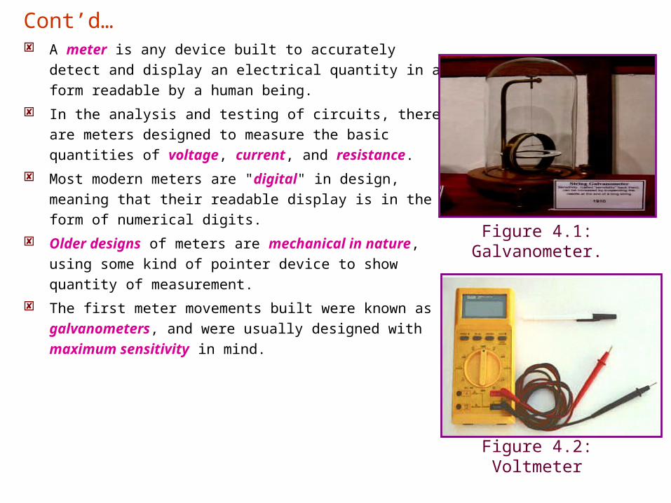
A meter is any device built to accurately detect and
display an electrical quantity in a form readable by a
human being.
In the analysis and testing of circuits, there are meters
designed to measure the basic quantities of voltage,
current, and resistance.
Most modern meters are "digital" in design, meaning that
their readable display is in the form of numerical digits.
Older designs of meters are mechanical in nature,
using some kind of pointer device to show quantity of
measurement.
The first meter movements built were known as
galvanometers, and were usually designed with
maximum sensitivity in mind.
Figure 4.2: Voltmeter
Figure 4.1: Galvanometer.
Cont’d…
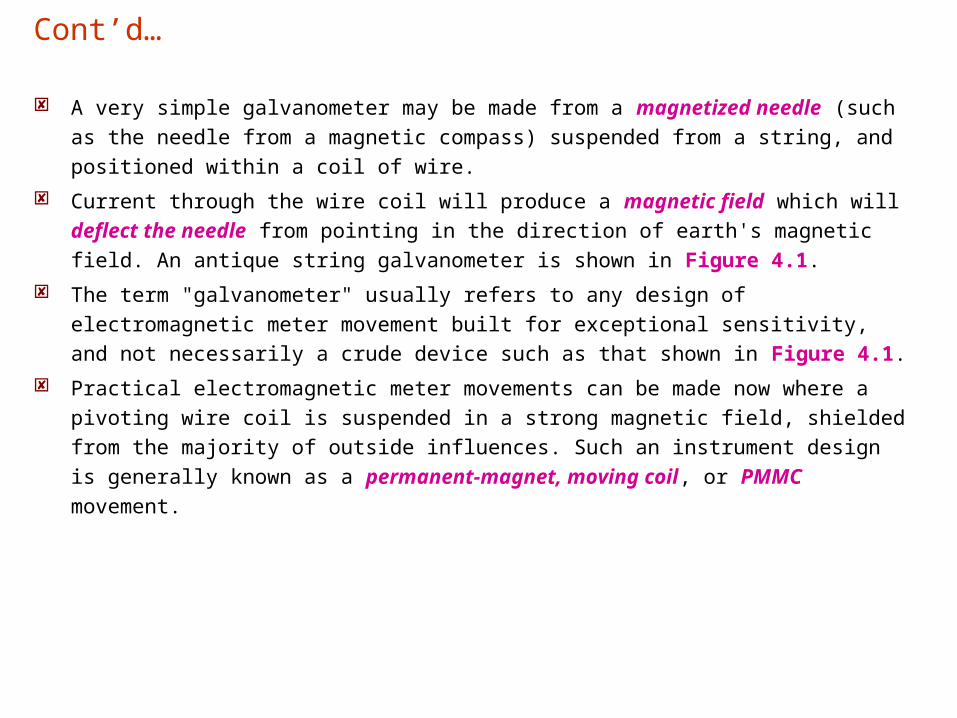
A very simple galvanometer may be made from a magnetized needle (such as the
needle from a magnetic compass) suspended from a string, and positioned within a
coil of wire.
Current through the wire coil will produce a magnetic field which will deflect the
needle from pointing in the direction of earth's magnetic field. An antique string
galvanometer is shown in Figure 4.1.
The term "galvanometer" usually refers to any design of electromagnetic meter
movement built for exceptional sensitivity, and not necessarily a crude device such
as that shown in Figure 4.1.
Practical electromagnetic meter movements can be made now where a pivoting
wire coil is suspended in a strong magnetic field, shielded from the majority of
outside influences. Such an instrument design is generally known as a permanent-
magnet, moving coil, or PMMC movement.
Cont’d…
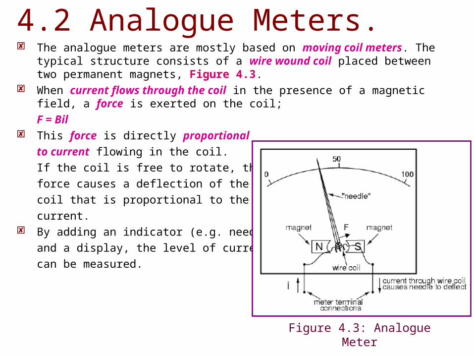
The analogue meters are mostly based on moving coil meters. The typical structure consists of a wire wound coil placed between two permanent magnets, Figure 4.3.
When current flows through the coil in the presence of a magnetic field, a force is exerted on the coil;
F = Bil This force is directly proportional
to current flowing in the coil.
If the coil is free to rotate, the
force causes a deflection of the
coil that is proportional to the
current. By adding an indicator (e.g. needle)
and a display, the level of current
can be measured.
4.2 Analogue Meters.
Figure 4.3: Analogue Meter
For a given meter, there is a maximum rated current that produces full-scale deflection of the indicator; FSD rating.
By adding external circuit components, the same basic moving coil meter can be used to measure different ranges of voltage or current.
Most meters are very sensitive. That is, they give full-scale deflection for a small fraction of an amp for example a typical FSD current rating for a moving coil meters is 50 μA, with internal wire resistance of 1 kΩ.
With no additional circuitry, the maximum voltage that can be measured using this meter is
50 x 10-6x 1000V = 0.05V.
Additional circuitry is needed for most practical measurements.
Cont’d…
The meter movement will have a pair of metal connection terminals on the back for current to enter and exit.
Most meter movements are polarity-sensitive, one direction of
current driving the needle to the right and the other driving it to the left.
Some meter movements are polarity-insensitive, relying on the
attraction of an unmagnetized, movable iron vane toward a stationary, current-carrying wire to deflect the needle. Such meters are ideally suited for the measurement of alternating current (AC).
A polarity-sensitive movement would just vibrate back and forth uselessly if connected to a source of AC.
4.3 Introduction DC Meters.
An increase in measured current will drive the needle to point further
to the right. A decrease will cause the needle to drop back down
toward its resting point on the left.
Most of the mechanical meter movements are based on
electromagnetism ; electron flow through a conductor creating a
perpendicular magnetic field,
A few are based on electrostatics; the attractive or repulsive force
generated by electric charges across space.
Cont’d…
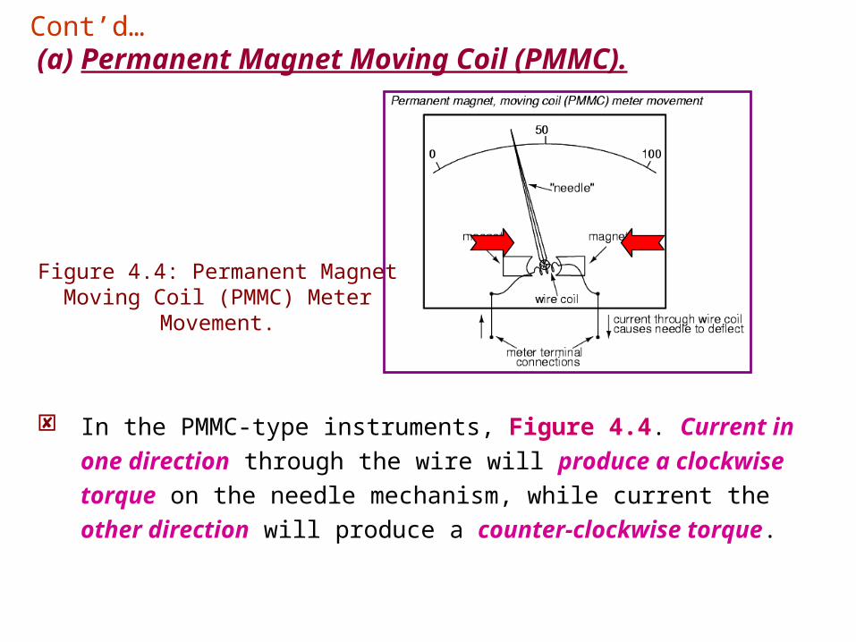
(a) Permanent Magnet Moving Coil (PMMC).Cont’d…
Figure 4.4: Permanent Magnet Moving Coil (PMMC) Meter
Movement.
In the PMMC-type instruments, Figure 4.4. Current in one direction
through the wire will produce a clockwise torque on the needle
mechanism, while current the other direction will produce a
counter-clockwise torque.
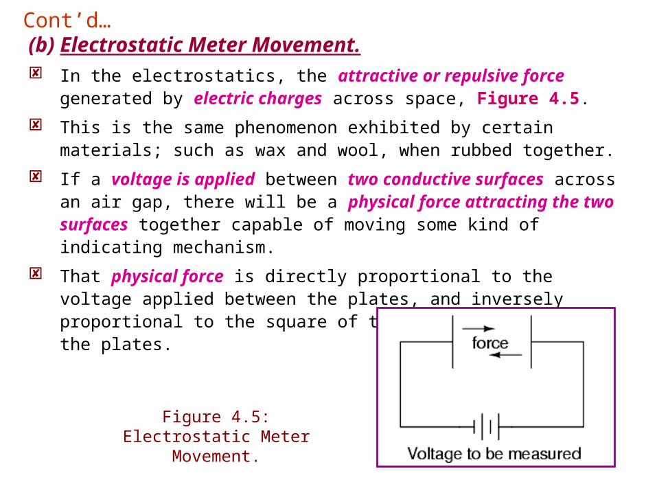
(b) Electrostatic Meter Movement. In the electrostatics, the attractive or repulsive force generated by
electric charges across space, Figure 4.5.
This is the same phenomenon exhibited by certain materials; such as wax and wool, when rubbed together.
If a voltage is applied between two conductive surfaces across an air gap, there will be a physical force attracting the two surfaces together capable of moving some kind of indicating mechanism.
That physical force is directly proportional to the voltage applied between the plates, and inversely proportional to the square of the
distance between the plates.
Cont’d…
Figure 4.5: Electrostatic Meter Movement.
The force is also irrespective of polarity, making this a polarity-
insensitive type of meter movement.
Unfortunately, the force generated by the electrostatic attraction is
very small for common voltages. It is so small that such meter
movement designs are impractical for use in general test instruments.
Typically, electrostatic meter movements are used for measuring
very high voltages; many thousands of volts.
One great advantage of the electrostatic meter movement, however, is
the fact that it has extremely high resistance, whereas
electromagnetic movements (which depend on the flow of electrons
through wire to generate a magnetic field) are much lower in resistance.
Cont’d…
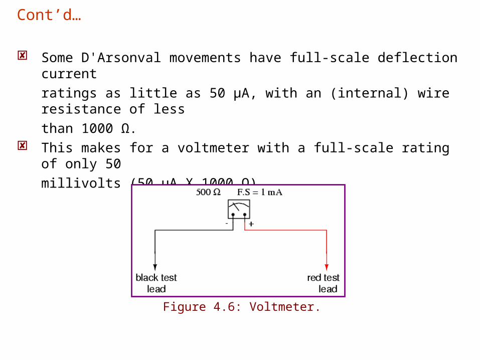
Some D'Arsonval movements have full-scale deflection current
ratings as little as 50 µA, with an (internal) wire resistance of less
than 1000 Ω. This makes for a voltmeter with a full-scale rating of only 50
millivolts (50 µA X 1000 Ω).
Cont’d…
Figure 4.6: Voltmeter.
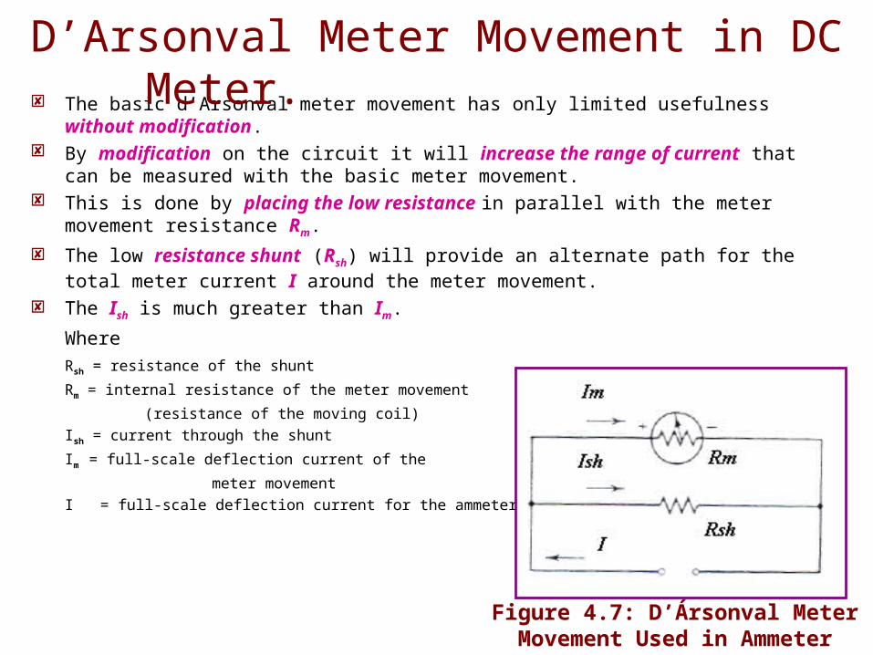
The basic d’Arsonval meter movement has only limited usefulness without modification.
By modification on the circuit it will increase the range of current that can be measured with the basic meter movement.
This is done by placing the low resistance in parallel with the meter movement resistance Rm.
The low resistance shunt (Rsh) will provide an alternate path for the total meter current I around the meter movement.
The Ish is much greater than Im.
Where
Rsh = resistance of the shunt
Rm = internal resistance of the meter movement
(resistance of the moving coil)
Ish = current through the shunt
Im = full-scale deflection current of the
meter movement
I = full-scale deflection current for the ammeter
Figure 4.7: D’Ársonval Meter Movement Used in Ammeter
Circuit
D’Arsonval Meter Movement in DC Meter.

The voltage drop across the meter movement
is Vm = ImRm
Since the shunt resistor is in parallel with the meter movement, the voltage drop across the shunt is equal to the voltage drop across the meter movement. That is,
Vsh = Vm
The current through the shunt is equal to the total current minus the current through the meter movement:,
Ish = I – Im
Knowing the voltage across, and the current through, the shunt allows us to determine the shunt resistance as
Rsh = Vsh/Ish
= ImRm/Ish = (Im/Ish)(Rm)
= Im/(I – Im)*Rm Ohm
Cont’d…
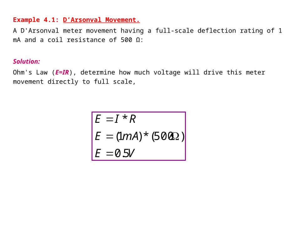
Example 4.1: D’Arsonval Movement.
A D'Arsonval meter movement having a full-scale deflection rating of 1 mA and a coil
resistance of 500 Ω:
Solution:
Ohm's Law (E=IR), determine how much voltage will drive this meter movement directly to
full scale,
VE
mAE
RIE
5.0
)500(*)1(
*
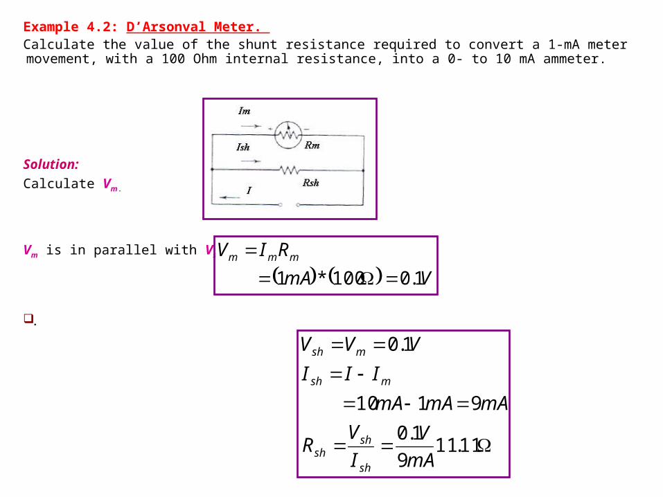
Example 4.2: D’Arsonval Meter. Calculate the value of the shunt resistance required to convert a 1-mA meter movement, with a 100 Ohm internal resistance, into a 0- to 10 mA ammeter.
Solution:
Calculate Vm.
Vm is in parallel with Vsh. KCL
.
VmA
RIV mmm
1.0100*1
11.119
1.0
9110
1.0
mA
V
I
VR
mAmAmA
III
VVV
sh
shsh
msh
msh
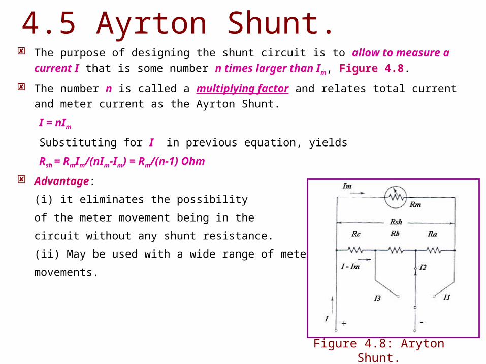
The purpose of designing the shunt circuit is to allow to measure a current I that is
some number n times larger than Im, Figure 4.8.
The number n is called a multiplying factor and relates total current and meter current
as the Ayrton Shunt.
I = nIm
Substituting for I in previous equation, yields
Rsh = RmIm/(nIm-Im) = Rm/(n-1) Ohm
Advantage:
(i) it eliminates the possibility
of the meter movement being in the
circuit without any shunt resistance.
(ii) May be used with a wide range of meter
movements.
4.5 Ayrton Shunt.
Figure 4.8: Aryton Shunt.
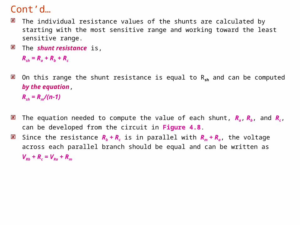
The individual resistance values of the shunts are calculated by starting with the most sensitive range and working toward the least sensitive range.
The shunt resistance is,
Rsh = Ra + Rb + Rc
On this range the shunt resistance is equal to Rsh and can be computed by the
equation,
Rsh = Rm/(n-1)
The equation needed to compute the value of each shunt, Ra, Rb, and Rc, can be
developed from the circuit in Figure 4.8.
Since the resistance Rb + Rc is in parallel with Rm + Ra, the voltage across each
parallel branch should be equal and can be written as
VRb + Rc = VRa + Rm
Cont’d…

In current and resistance terms we can write
(Rb + Rc) (I2-Im)=Im (Ra +Rm)
or
I2(Rb + Rc) - Im(Rb + Rc)= Im[Rsh-(Rb + Rc)+Rm]
Multiplying through by Im on the right yields
I2(Rb + Rc) - Im(Rb + Rc) = ImRsh- Im(Rb + Rc)+ImRm
This can be rewritten as
Rb+ Rc = Im (Rsh+ Rm)/I2
Having already found the total shunt resistance Rsh, we can now determine Ra as
Ra = Rsh – (Rb + Rc)
The current I is the maximum current for the range on which the ammeter is set. The resistor Rc can be determined from
Rc = Im(Rsh+ Rm)/I3
The resistor Rb can now be computed as, Rb = (Rb + Rc) – Rc
Cont’d…
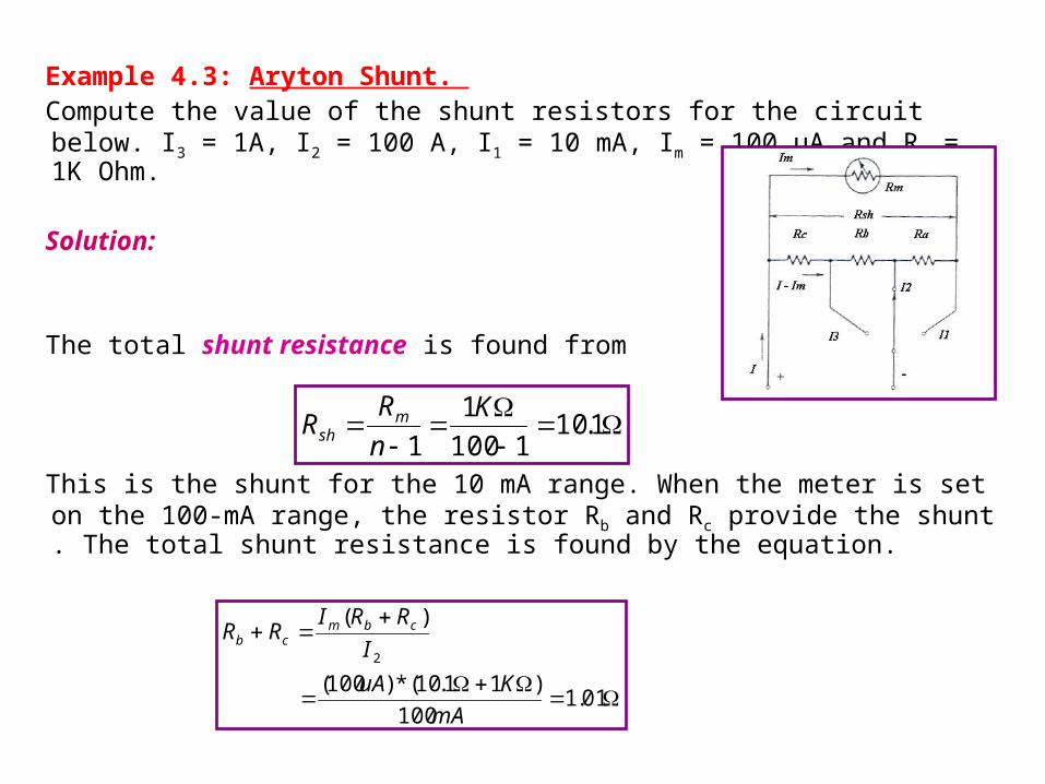
Example 4.3: Aryton Shunt.
Compute the value of the shunt resistors for the circuit below. I3 = 1A, I2 = 100 A, I1 = 10 mA, Im = 100 uA and Rm = 1K Ohm.
Solution:
The total shunt resistance is found from
This is the shunt for the 10 mA range. When the meter is set on the 100-mA range, the resistor Rb and Rc provide the shunt . The total shunt resistance is found by the equation.
1.101100
1
1
K
n
RR msh
01.1100
)11.10(*)100(
)(
2
mA
KuA
I
RRIRR cbmcb
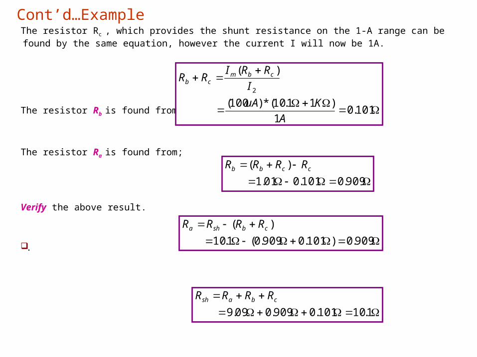
The resistor Rc , which provides the shunt resistance on the 1-A range can be found by the same equation, however the current I will now be 1A.
The resistor Rb is found from the equation below;
The resistor Ra is found from;
Verify the above result.
.
101.01
)11.10(*)100(
)(
2
A
KuA
I
RRIRR cbmcb
Cont’d…Example
909.0101.001.1
)( ccbb RRRR
909.0)101.0909.0(1.10
)( cbsha RRRR
1.10101.0909.009.9cbash RRRR
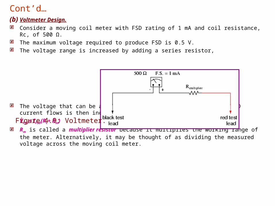
(b) Voltmeter Design. Consider a moving coil meter with FSD rating of 1 mA and coil resistance, Rc, of 500 Ω. The maximum voltage required to produce FSD is 0.5 V. The voltage range is increased by adding a series resistor,
The voltage that can be applied to the – and + terminals before FSD current flows is then increased to:
VFSD= IFSD(Rc+ Rm)
Rm is called a multiplier resistor because it multiplies the working range of the meter. Alternatively, it may be thought of as dividing the measured voltage across the moving coil meter.
Cont’d…
Figure 4.9: Voltmeter.
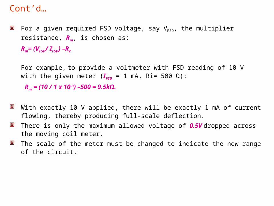
For a given required FSD voltage, say VFSD, the multiplier resistance, Rm, is
chosen as:
Rm= (VFSD/ IFSD) –Rc
For example, to provide a voltmeter with FSD reading of 10 V with the given meter (IFSD = 1 mA, Ri= 500 Ω):
Rm = (10 / 1 x 10⁻³) –500 = 9.5kΩ.
With exactly 10 V applied, there will be exactly 1 mA of current flowing, thereby producing full-scale deflection.
There is only the maximum allowed voltage of 0.5V dropped across the moving coil meter.
The scale of the meter must be changed to indicate the new range of the circuit.
Cont’d…
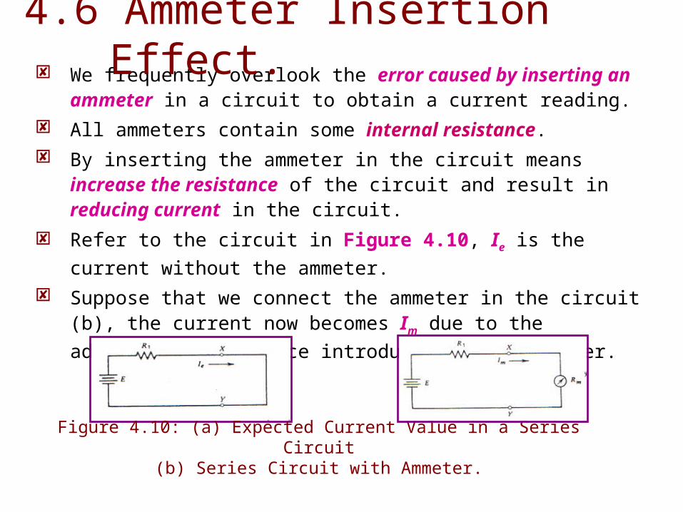
We frequently overlook the error caused by inserting an ammeter in a circuit to obtain a current reading.
All ammeters contain some internal resistance. By inserting the ammeter in the circuit means increase the
resistance of the circuit and result in reducing current in the circuit.
Refer to the circuit in Figure 4.10, Ie is the current without the
ammeter. Suppose that we connect the ammeter in the circuit (b), the current
now becomes Im due to the additional resistance introduced by the
ammeter.
4.6 Ammeter Insertion Effect.
Figure 4.10: (a) Expected Current Value in a Series Circuit(b) Series Circuit with Ammeter.
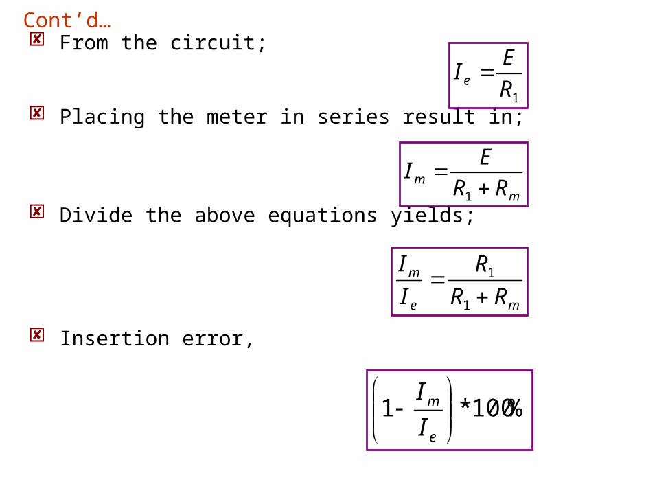
From the circuit;
Placing the meter in series result in;
Divide the above equations yields;
Insertion error,
1R
EI e
Cont’d…
mm RR
EI
1
me
m
RR
R
I
I
1
1
%100*1
e
m
I
I
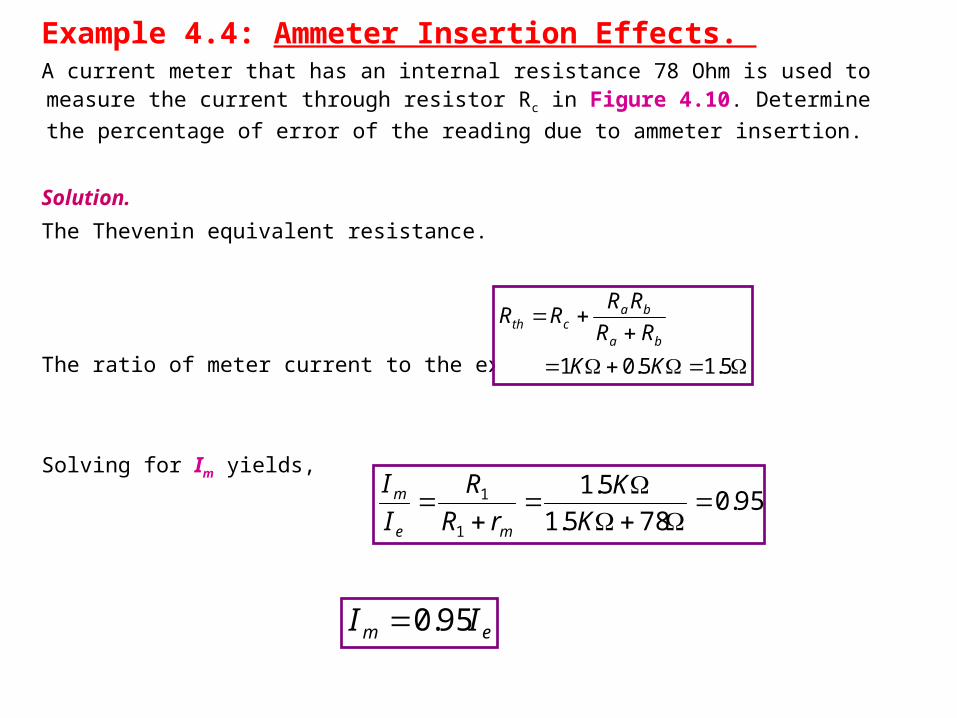
Example 4.4: Ammeter Insertion Effects. A current meter that has an internal resistance 78 Ohm is used to measure the current through resistor Rc in Figure 4.10. Determine the percentage of error of the reading due
to ammeter insertion.
Solution.
The Thevenin equivalent resistance.
The ratio of meter current to the expected current is,
Solving for Im yields,
5.15.01 KK
RR
RRRR
ba
bacth
95.0785.1
5.1
1
1
K
K
rR
R
I
I
me
m
em II 95.0
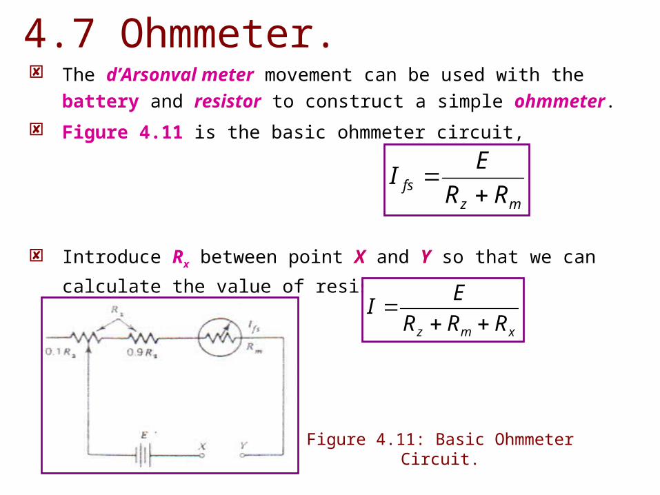
The d’Arsonval meter movement can be used with the battery and
resistor to construct a simple ohmmeter.
Figure 4.11 is the basic ohmmeter circuit,
Introduce Rx between point X and Y so that we can calculate the
value of resistance.
mzfs RR
EI
4.7 Ohmmeter.
Figure 4.11: Basic Ohmmeter Circuit.
xmz RRR
EI
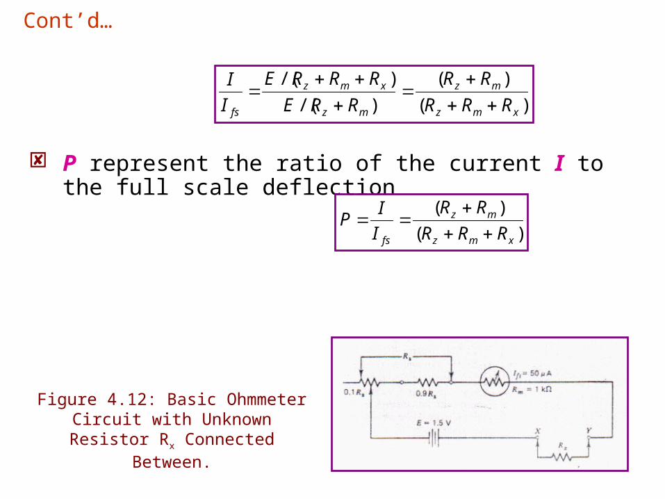
P represent the ratio of the current I to the full scale deflection
Cont’d…
)(
)(
)/(
)/(
xmz
mz
mz
xmz
fs RRR
RR
RRE
RRRE
I
I
)(
)(
xmz
mz
fs RRR
RR
I
IP
Figure 4.12: Basic Ohmmeter Circuit with Unknown Resistor Rx Connected
Between.
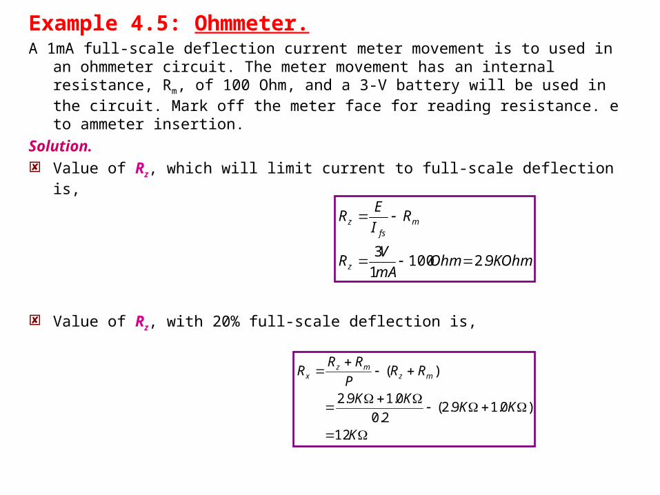
Example 4.5: Ohmmeter.A 1mA full-scale deflection current meter movement is to used in an
ohmmeter circuit. The meter movement has an internal resistance, Rm, of 100 Ohm, and a 3-V battery will be used in the circuit. Mark off the meter face for reading resistance. e to ammeter insertion.
Solution. Value of Rz, which will limit current to full-scale deflection is,
Value of Rz, with 20% full-scale deflection is,
KOhmOhmmA
VR
RI
ER
z
mfs
z
9.21001
3
K
KKKK
RRP
RRR mz
mzx
12
)0.19.2(2.0
0.19.2
)(
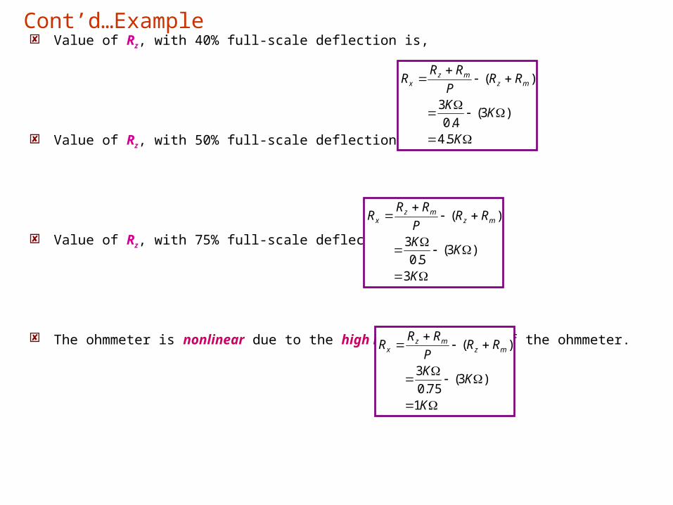
Value of Rz, with 40% full-scale deflection is,
Value of Rz, with 50% full-scale deflection is,
Value of Rz, with 75% full-scale deflection is,
The ohmmeter is nonlinear due to the high internal resistance of the ohmmeter.
Cont’d…Example
K
KK
RRP
RRR mz
mzx
1
)3(75.0
3
)(
K
KK
RRP
RRR mz
mzx
5.4
)3(4.0
3
)(
K
KK
RRP
RRR mz
mzx
3
)3(5.0
3
)(
5.1 Introduction to AC Meters.
5.2 D’Arsonval Meter Movement with Half-Wave Rectification.
5.3 D’Arsonval Meter Movement with Full-Wave Rectification.
5.0 AC Meters.
5.1 Introduction to AC Meters.
Five principal meter movement that are commonly used in ac
instruments;
(i) Electrodynamometer.
(ii) Iron-Vane.
(iii) Electrostatic.
(iv) Thermocouple.
(v) D’Arsonval (PMMC) with rectifier.
The d’Arsonval meter is the most frequently used meter movement,
event though it cannot directly measure alternating current or voltage.
In this chapter it will discuss the instruments for measuring alternating
signal that use the d’Arsonval meter movement.
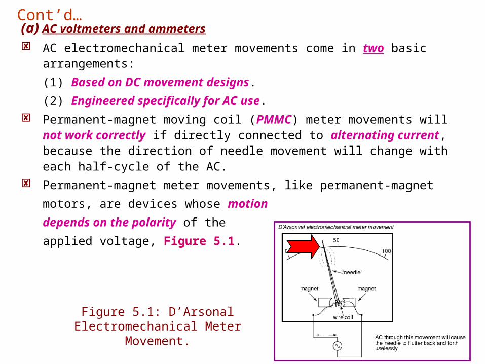
(a) AC voltmeters and ammeters
AC electromechanical meter movements come in two basic arrangements:
(1) Based on DC movement designs.
(2) Engineered specifically for AC use. Permanent-magnet moving coil (PMMC) meter movements will not work
correctly if directly connected to alternating current, because the direction of needle movement will change with each half-cycle of the AC.
Permanent-magnet meter movements, like permanent-magnet
motors, are devices whose motion
depends on the polarity of the
applied voltage, Figure 5.1.
Figure 5.1: D’Arsonal Electromechanical Meter Movement.
Cont’d…
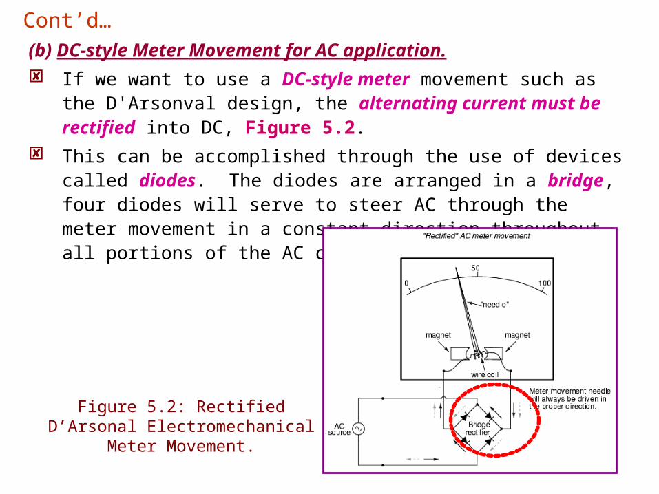
(b) DC-style Meter Movement for AC application. If we want to use a DC-style meter movement such as the
D'Arsonval design, the alternating current must be rectified into DC, Figure 5.2.
This can be accomplished through the use of devices called diodes. The diodes are arranged in a bridge, four diodes will serve to steer AC through the meter movement in a constant direction throughout all portions of the AC cycle:
Figure 5.2: Rectified D’Arsonal Electromechanical Meter Movement.
Cont’d…
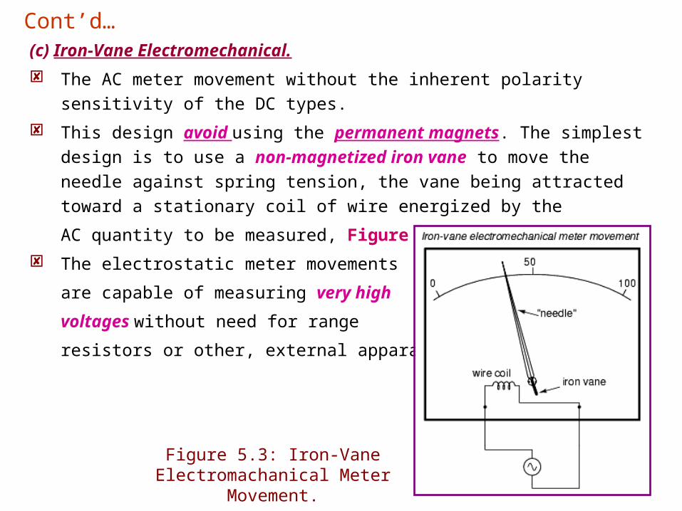
(c) Iron-Vane Electromechanical.
The AC meter movement without the inherent polarity sensitivity of the DC
types.
This design avoid using the permanent magnets. The simplest design is
to use a non-magnetized iron vane to move the needle against spring
tension, the vane being attracted toward a stationary coil of wire energized
by the
AC quantity to be measured, Figure 5.3.
The electrostatic meter movements
are capable of measuring very high
voltages without need for range
resistors or other, external apparatus.
Figure 5.3: Iron-Vane Electromachanical Meter Movement.
Cont’d…
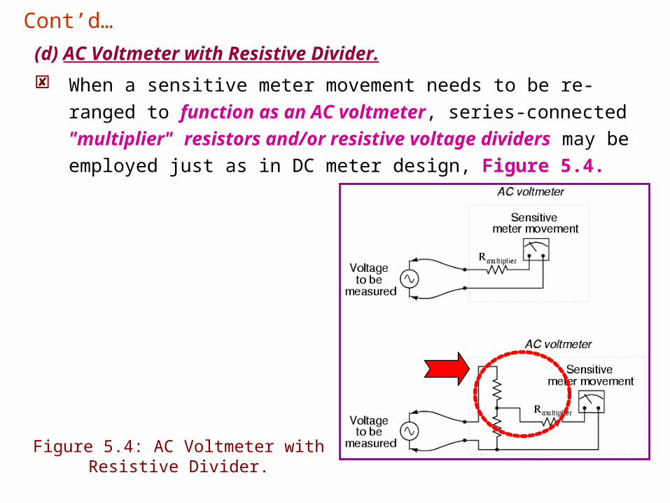
(d) AC Voltmeter with Resistive Divider.
When a sensitive meter movement needs to be re-ranged to
function as an AC voltmeter, series-connected "multiplier"
resistors and/or resistive voltage dividers may be employed just
as in DC meter design, Figure 5.4.
Figure 5.4: AC Voltmeter with Resistive Divider.
Cont’d…
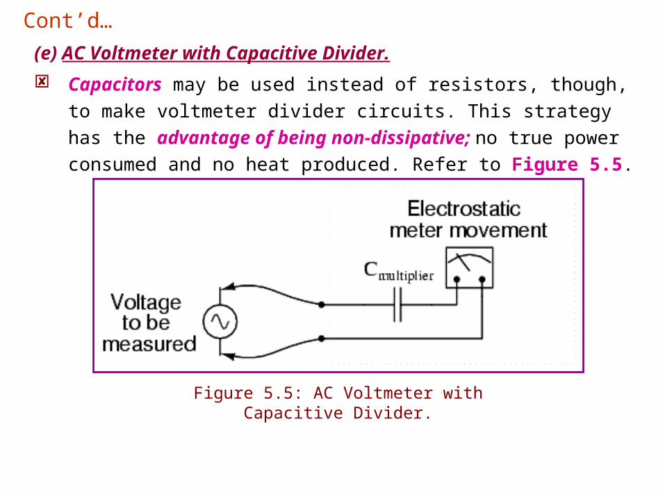
(e) AC Voltmeter with Capacitive Divider.
Capacitors may be used instead of resistors, though, to make
voltmeter divider circuits. This strategy has the advantage of being
non-dissipative; no true power consumed and no heat produced.
Refer to Figure 5.5.
Figure 5.5: AC Voltmeter with Capacitive Divider.
Cont’d…
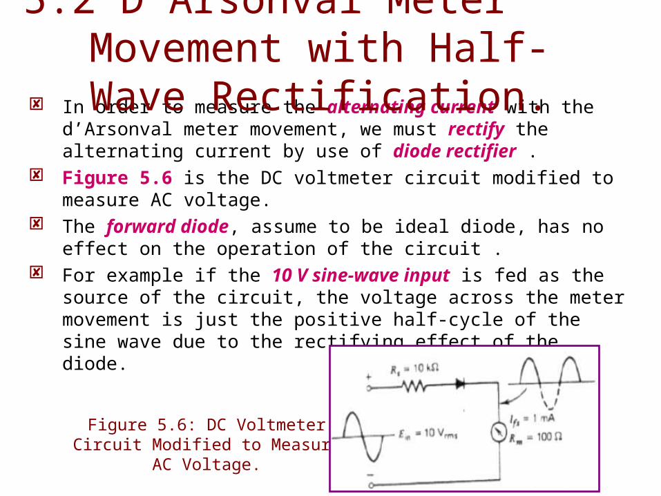
In order to measure the alternating current with the d’Arsonval meter movement, we must rectify the alternating current by use of diode rectifier .
Figure 5.6 is the DC voltmeter circuit modified to measure AC voltage.
The forward diode, assume to be ideal diode, has no effect on the operation of the circuit .
For example if the 10 V sine-wave input is fed as the source of the circuit, the voltage across the meter movement is just the positive half-cycle of the sine wave due to the rectifying effect of the diode.
5.2 D’Arsonval Meter Movement with Half-Wave Rectification.
Figure 5.6: DC Voltmeter Circuit Modified to Measure AC Voltage.
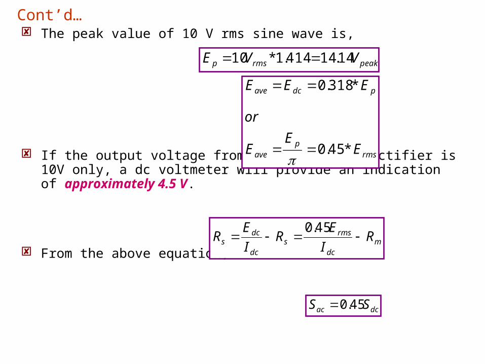
The peak value of 10 V rms sine wave is,
If the output voltage from the half-wave rectifier is 10V only, a dc voltmeter will provide an indication of approximately 4.5 V.
From the above equation,
rmsp
ave
pdcave
EE
E
or
EEE
*45.0
*318.0
Cont’d…
mdc
rmss
dc
dcs R
I
ER
I
ER
45.0
peakrmsp VVE 14.14414.1*10
dcac SS 45.0
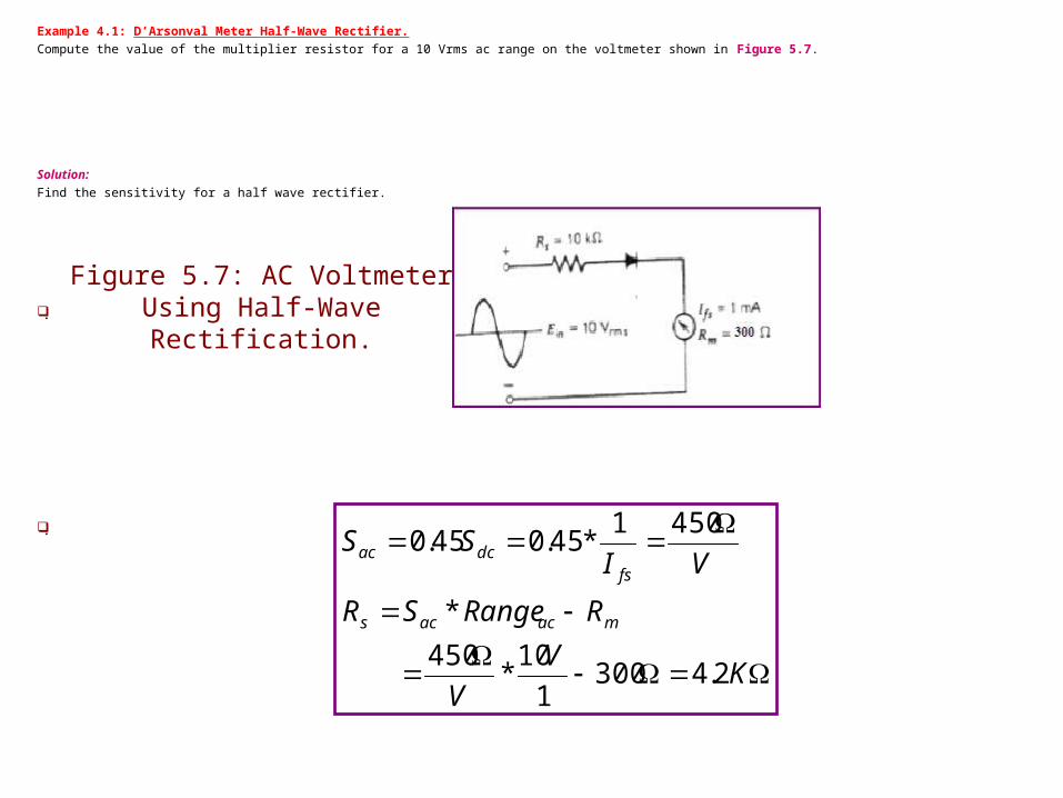
Example 4.1: D’Arsonval Meter Half-Wave Rectifier.
Compute the value of the multiplier resistor for a 10 Vrms ac range on the voltmeter shown in Figure 5.7.
Solution:
Find the sensitivity for a half wave rectifier.
.
.
KV
V
RRangeSR
VISS
macacs
fsdcac
2.43001
10*
450
*
4501*45.045.0
Figure 5.7: AC Voltmeter Using Half-Wave Rectification.
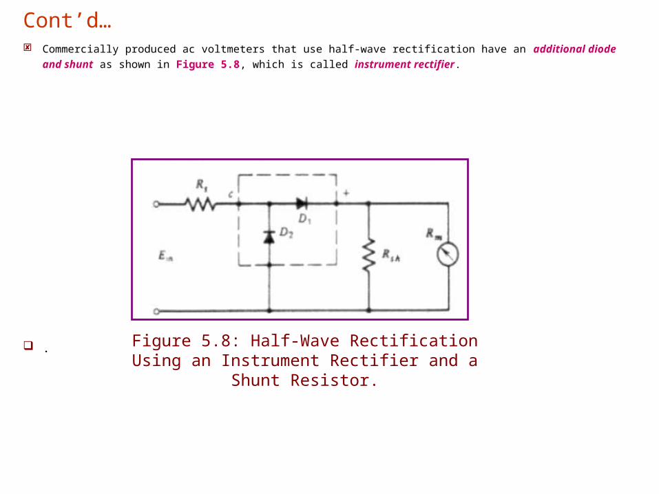
Commercially produced ac voltmeters that use half-wave rectification have an additional diode and shunt as shown
in Figure 5.8, which is called instrument rectifier.
.Figure 5.8: Half-Wave Rectification Using an Instrument Rectifier and a Shunt Resistor.
Cont’d…
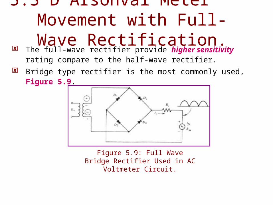
The full-wave rectifier provide higher sensitivity rating compare to the half-wave rectifier.
Bridge type rectifier is the most commonly used, Figure 5.9.
5.3 D’Arsonval Meter Movement with Full-Wave Rectification.
Figure 5.9: Full Wave Bridge Rectifier Used in AC Voltmeter
Circuit.
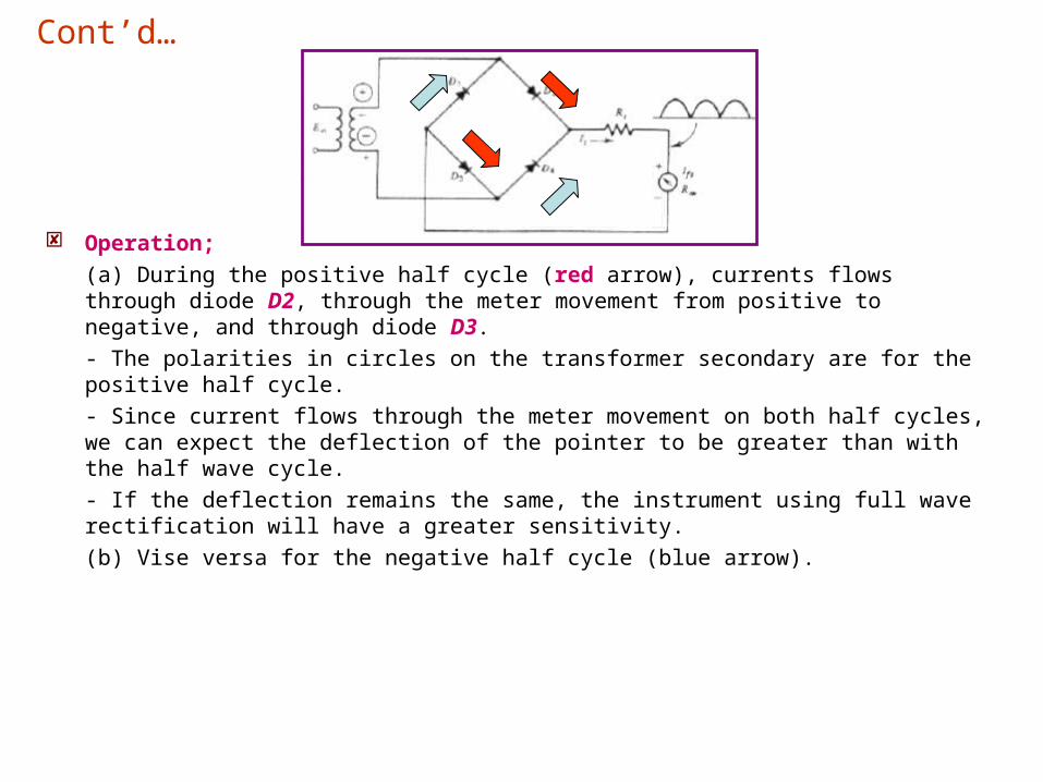
Operation;
(a) During the positive half cycle (red arrow), currents flows through diode D2, through the meter movement from positive to negative, and through diode D3.
- The polarities in circles on the transformer secondary are for the positive half cycle.
- Since current flows through the meter movement on both half cycles, we can expect the deflection of the pointer to be greater than with the half wave cycle.
- If the deflection remains the same, the instrument using full wave rectification will have a greater sensitivity.
(b) Vise versa for the negative half cycle (blue arrow).
Cont’d…
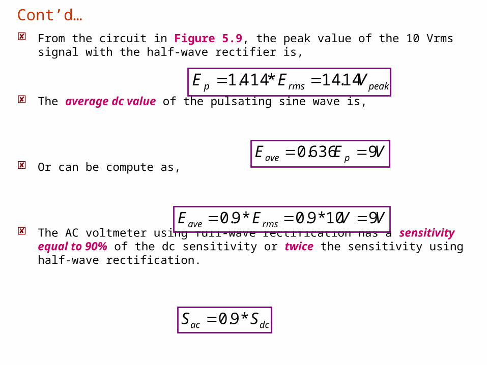
From the circuit in Figure 5.9, the peak value of the 10 Vrms signal with the half-wave rectifier is,
The average dc value of the pulsating sine wave is,
Or can be compute as,
The AC voltmeter using full-wave rectification has a sensitivity equal to 90% of the dc sensitivity or twice the sensitivity using half-wave rectification.
peakrmsp VEE 14.14*414.1
Cont’d…
VEE pave 9636.0
VVEE rmsave 910*9.0*9.0
dcac SS *9.0

Example 4.2: D’Arsonval Meter Full-Wave Rectifier.
Each diode in the full-wave rectifier circuit in Figure 5.10 has an average forward bias resistance of 50 Ohm and is assumed to have an infinite resistance in the reverse direction. Calculate,
(a) The multiplier Rs.
(b) The AC sensitivity.
© The equivalent DC sensitivity.
Solution:
(a) Calculate the current shunt and total current,
.
mAmAmAIII
and
mAmA
R
EI
mshT
sh
msh
211
1500
500*1
Figure 5.10: AC Voltmeter Using Full-Wave Rectification and Shunt.
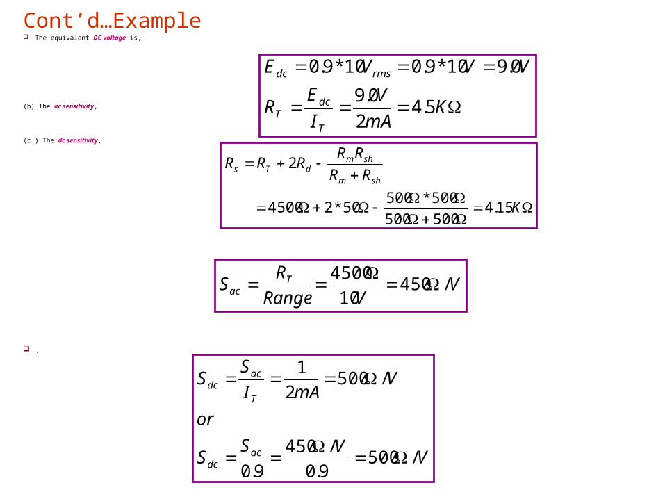
The equivalent DC voltage is,
(b) The ac sensitivity,
(c.) The dc sensitivity,
.
KmA
V
I
ER
VVVE
T
dcT
rmsdc
5.42
0.9
0.910*9.010*9.0
Cont’d…Example
K
RR
RRRRR
shm
shmdTs
15.4500500
500*50050*24500
2
VVRange
RS Tac /450
10
4500
VVS
S
or
VmAI
SS
acdc
T
acdc
/5009.0
/450
9.0
/5002
1