Embed Size (px)
Citation preview

Please read and save this Repair Parts Manual. Read this manual and the General Operating Instructions carefully before attempting to assemble, install, operate or maintain the product described. Protect yourself and others by observing all safety information. The Safety Instructions are contained in the General Operating Instructions. Failure to comply with the safety instructions accompanying this product could result in personal injury and/or property damage! Retain instructions for future reference.
Dayton Operating Instructions, Performance,Specifications and Parts Manual
Form 5S6692 Printed in India09701Version 1
LUB20005/11Form # 580
The Dayton in-line centrifugal pumps are designed for a wide range of applications involving the transfer of liquids, circulation and pressure boosting of hot or cold clean water and any thin, non-explosive liquids which do not contain any solid particles or fibers and those liquids that do not attack chemically, the pump material of construction.
Description
Specifications
fire fighting systems, pressure boosting and municipal water supply, boiler feed and condensate systems, cooling water systems and irrigation.
The typical areas where the vertical inline pumps are widely used is as under,
Dayton Centrifugal Pumps
Vertical Multistage
Figure 1
Liquid Temperature.............248°F maxLiquid Viscocity....................100 SSU maxMax. Case Pressure..............362 psiImpeller Type........................ClosedSeal Type...............................Bellow Type (SIC/CARBON, Stainless steel, EPDM) Flange Connection...............Class 250 as per ANSI B 16.1Speed....................................3450 RPMMotor....................................Totally Enclosed Fan Cooled Construction (56 C Frame)
and are rated for continous operationAmbient temperature.........104°FFrequency.............................60HzSingle Phase.........................Capacitor Start and includes overload protectionThree Phase..........................Must be installed with magnetic starter which
provides 3 leg protection.
Motor....................................
Three Phase..........................
ModelsCast Iron Stainless Steel
5UWH55UWH65UWH75UWH85UWH95UWJ05UWJ15UWJ25UWJ35UWJ45UWJ55UWJ65UWJ75UWJ85UWJ95UWK0
5UWK15UWK25UWK35UWK45UWK55UWK65UWK75UWK85UWK95UWL05UWL15UWL25UWL35UWL45UWL55UWL6
HP Phase Voltage AmpsService Factor Suction Discharge Stages
Port Size
0.50.50.750.750.750.7511.5232311.523
1313131111113333
115/208-230208-230/460115/208-230208-230/460115/208-230208-230/460115/208-230115/208-230115/208-230
230115/208-230
230208-230/460208-230/460208-230/460208-230/460
8.6/4.0-4.31.7-1.6/0.810.7/5.2-5.32.5-2.4/1.210.7/5.2-5.32.5-2.4/1.212.2/6.3-6.113.5/7.6-6.716.6/9.4-8.3
12.516.6/9.4-8.3
12.53.3-3.2/1.64.5-4.6/2.36.0-5.8/2.98.3-7.6/3.8
1.151.151.151.151.151.151.151.151.201.001.201.001.151.151.201.15
1-¼"1-¼"1-¼"1-¼"1-¼"1-¼"1-¼"1-¼"1-¼"1-¼"1-¼"1-¼"1-¼"1-¼"1-¼"1-¼"
1-¼"1-¼"1-¼"1-¼"1-¼"1-¼"1-¼"1-¼"1-¼"1-¼"1-¼"1-¼"1-¼"1-¼"1-¼"1-¼"
22223358111759581117
Cast Iron Models 5UWH5 thru Stainless Steel Models 5UWK1 thru 5UWK9 and 5UWL0 thru 5UWL6
5UWH9, 5UWJ0 thru 5UWJ9 and 5UWK0
2
Dayton Operating Instructions, Performance,Specifications and Parts Manual
Cast Iron Models 5UWH5 thru 5UWH9, 5UWJ0 thru 5UWJ9 and 5UWK0Stainless Steel Models 5UWK1 thru 5UWK9 and 5UWL0 thru 5UWL6
Dayton Centrifugal Pumps
Vertical Multistage
Performance
ModelsCast Iron Stainless Steel HP Phase
0.50.50.750.750.750.7511.5232311.523
1313131111113330
Gallons per Minute At Pressure in PSI
10 20 40 60 80 100 120 140 160 180 200
Max. Pressure
(PSI)
21214040************
121220201919**********
------1722**35*1722**
------61922*144261922*
-------1419*-35-1419*
-------51622-25-51622
--------1220-9--1220
--------418----418
---------16-----16
---------13-----13
---------10-----10
272727274040661081482307012766108148230
5UWK15UWK25UWK35UWK45UWK55UWK65UWK75UWK85UWK95UWL05UWL15UWL25UWL35UWL45UWL55UWL6
5UWH55UWH65UWH75UWH85UWH95UWJ05UWJ15UWJ25UWJ35UWJ45UWJ55UWJ65UWJ75UWJ85UWJ95UWK0
Models Impeller Shaft Bowl
S.S.304S.S.304S.S.304S.S.304S.S.304S.S.304S.S.304S.S.304S.S.304S.S.304S.S.304S.S.304S.S.304S.S.304S.S.304S.S.304
S.S.304S.S.304S.S.304S.S.304S.S.304S.S.304S.S.304S.S.304S.S.304S.S.304S.S.304S.S.304S.S.304S.S.304S.S.304S.S.304
S.S.316S.S.316S.S.316S.S.316S.S.316S.S.316S.S.316S.S.316S.S.316S.S.316S.S.316S.S.316S.S.316S.S.316S.S.316S.S.316
S.S.316S.S.316S.S.316S.S.316S.S.316S.S.316S.S.316S.S.316S.S.316S.S.316S.S.316S.S.316S.S.316S.S.316S.S.316S.S.316
S.S.304S.S.304S.S.304S.S.304S.S.304S.S.304S.S.304S.S.304S.S.304S.S.304S.S.304S.S.304S.S.304S.S.304S.S.304S.S.304
S.S.304S.S.304S.S.304S.S.304S.S.304S.S.304S.S.304S.S.304S.S.304S.S.304S.S.304S.S.304S.S.304S.S.304S.S.304S.S.304
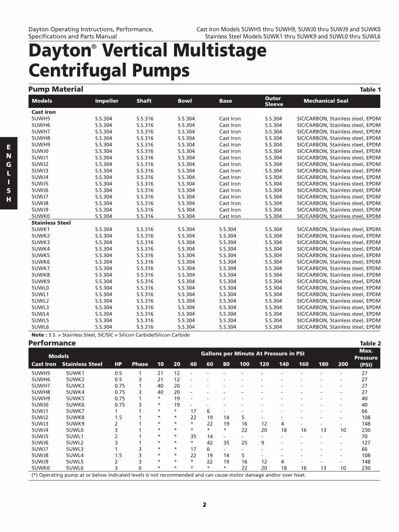
Pump Material
Cast Iron5UWH55UWH65UWH75UWH85UWH95UWJ05UWJ15UWJ25UWJ35UWJ45UWJ55UWJ65UWJ75UWJ85UWJ95UWK0Stainless Steel5UWK15UWK25UWK35UWK45UWK55UWK65UWK75UWK85UWK95UWL05UWL15UWL25UWL35UWL45UWL55UWL6
(*) Operating pump at or below indicated levels is not recommended and can cause motor damage and/or over heat.
Base
Cast IronCast IronCast IronCast IronCast IronCast IronCast IronCast IronCast IronCast IronCast IronCast IronCast IronCast IronCast IronCast Iron
S.S.304S.S.304S.S.304S.S.304S.S.304S.S.304S.S.304S.S.304S.S.304S.S.304S.S.304S.S.304S.S.304S.S.304S.S.304S.S.304
Outer Sleeve S.S.304S.S.304S.S.304S.S.304S.S.304S.S.304S.S.304S.S.304S.S.304S.S.304S.S.304S.S.304S.S.304S.S.304S.S.304S.S.304
S.S.304S.S.304S.S.304S.S.304S.S.304S.S.304S.S.304S.S.304S.S.304S.S.304S.S.304S.S.304S.S.304S.S.304S.S.304S.S.304
Mechanical Seal
SIC/CARBON, Stainless steel, EPDMSIC/CARBON, Stainless steel, EPDMSIC/CARBON, Stainless steel, EPDMSIC/CARBON, Stainless steel, EPDMSIC/CARBON, Stainless steel, EPDMSIC/CARBON, Stainless steel, EPDMSIC/CARBON, Stainless steel, EPDMSIC/CARBON, Stainless steel, EPDMSIC/CARBON, Stainless steel, EPDMSIC/CARBON, Stainless steel, EPDMSIC/CARBON, Stainless steel, EPDMSIC/CARBON, Stainless steel, EPDMSIC/CARBON, Stainless steel, EPDMSIC/CARBON, Stainless steel, EPDMSIC/CARBON, Stainless steel, EPDMSIC/CARBON, Stainless steel, EPDM
SIC/CARBON, Stainless steel, EPDMSIC/CARBON, Stainless steel, EPDMSIC/CARBON, Stainless steel, EPDMSIC/CARBON, Stainless steel, EPDMSIC/CARBON, Stainless steel, EPDMSIC/CARBON, Stainless steel, EPDMSIC/CARBON, Stainless steel, EPDMSIC/CARBON, Stainless steel, EPDMSIC/CARBON, Stainless steel, EPDMSIC/CARBON, Stainless steel, EPDMSIC/CARBON, Stainless steel, EPDMSIC/CARBON, Stainless steel, EPDMSIC/CARBON, Stainless steel, EPDMSIC/CARBON, Stainless steel, EPDMSIC/CARBON, Stainless steel, EPDMSIC/CARBON, Stainless steel, EPDM
Table 1
Note : S.S. = Stainless Steel, SIC/SIC = Silicon Carbide/Silicon Carbide
Table 2

D2
D1
B2
B1
3/4" x 1-1/9"G 1/2
A1
A2
A3
A4
7-3/32"
8-21/32"
1-3/8" 4 x 5/9"
3-1/
2"
3-8/
9"
5-1/
2"
G 1/2 G 1/2A
5
Dimensions (Inches)
5UWH55UWH65UWH75UWH85UWH95UWJ05UWJ15UWJ25UWJ35UWJ45UWJ55UWJ65UWJ75UWJ85UWJ95UWK0
3
Cast Iron Models Stages
22223358111759581117
D1 D2B1 B2
Figure 2
11-3/32”11-3/32”11-51/64”11-51/64”11-51/64”11-51/64”11-13/64”15-13/32”17-1/2”
21-45/64”15”
19-19/64”13-13/64”15-13/32”17-1/2”
21-45/64”
10- 51/ 64” 9- 51/ 64”
11- 13/ 32” 10- 13/ 64” 11- 13/ 32” 10- 13/ 64” 12- 13/ 64”
11” 11- 19/ 32” 12- 51/ 64” 11- 19/ 32” 12- 51/ 64” 11- 13/ 32” 10- 13/ 32”
11”11-51/64”
6- 19/ 64” 6- 19/ 64” 6- 19/ 64” 6- 19/ 64” 6- 19/ 64” 6- 19/ 64” 6- 19/ 64” 7- 19/ 64” 7- 19/ 64” 7- 19/ 64” 7- 19/ 64” 7- 19/ 64” 6- 19/ 64” 7- 19/ 64” 7- 19/ 64” 7- 19/ 64”
4- 29/ 32” 4- 29/ 32” 4- 29/ 32” 4- 29/ 32” 4- 29/ 32” 4- 29/ 32” 4- 29/ 32” 5- 19/ 64” 5- 19/ 64” 5- 19/ 64” 5- 19/ 64” 5- 19/ 64” 4- 29/ 32” 5- 19/ 64” 5- 19/ 64” 5- 19/ 64”
A1 A2 A3 A4 A5
2- 61/ 64” 2- 61/ 64” 2- 61/ 64” 2- 61/ 64” 2- 61/ 64” 2- 61/ 64” 2- 61/ 64” 2- 61/ 64” 2- 61/ 64” 2- 61/ 64” 2- 61/ 64” 2- 61/ 64” 2- 61/ 64” 2- 61/ 64” 2- 61/ 64” 2- 61/ 64”
3- 15/ 16” 3- 15/ 16” 3- 15/ 16” 3- 15/ 16” 3- 15/ 16” 3- 15/ 16” 3- 15/ 16” 3- 15/ 16” 3- 15/ 16” 3- 15/ 16” 3- 15/ 16” 3- 15/ 16” 3- 15/ 16” 3- 15/ 16” 3- 15/ 16” 3- 15/ 16”
5- 35/ 64” 5- 35/ 64” 5- 35/ 64” 5- 35/ 64” 5- 35/ 64” 5- 35/ 64” 5- 35/ 64” 5- 35/ 64” 5- 35/ 64” 5- 35/ 64” 5- 35/ 64” 5- 35/ 64” 5- 35/ 64” 5- 35/ 64” 5- 35/ 64” 5- 35/ 64”
9- 27/ 32”9- 27/ 32”9- 27/ 32”9- 27/ 32”9- 27/ 32”9- 27/ 32”9- 27/ 32”9- 27/ 32”9- 27/ 32”9- 27/ 32”9- 27/ 32”9- 27/ 32”9- 27/ 32”9- 27/ 32”9- 27/ 32”9- 27/ 32”
51/64”51/64”51/64”51/64”51/64”51/64”51/64”51/64”51/64”51/64”51/64”51/64”51/64”51/64”51/64”51/64”
Dayton Operating Instructions, Performance,Specifications and Parts Manual
Cast Iron Models 5UWH5 thru 5UWH9, 5UWJ0 thru 5UWJ9 and 5UWK0Stainless Steel Models 5UWK1 thru 5UWK9 and 5UWL0 thru 5UWL6
Table 3
Class 250 Flange Connection

Figure 3
B2
B1
D2
D1
G 1/2G 1/2
A1
A2
A4
A5
5/9" 3/4" x 1-1/9"
Ø32Ø85
7-3/32"
3-1/
2"
4-1/
8"
5-1/
2"
Dimensions (Inches)
5UWK15UWK25UWK35UWK45UWK55UWK65UWK75UWK85UWK95UWL05UWL15UWL25UWL35UWL45UWL55UWL6
4
Stainless SteelModels Stages
22223358111759581117
D1 D2B1 B2
11-3/32”11-3/32”
11-51/64”11-51/64”11-51/64”11-51/64”11-13/64”15-13/32”17-1/2”
21-45/64”15”
19-19/64”13-13/64”15-13/32”17-1/2”
21-45/64”
10- 51/ 64” 9- 51/ 64”
11- 13/ 32” 10- 13/ 64” 11- 13/ 32” 10- 13/ 64” 12- 13/ 64”
11” 11- 19/ 32” 12- 51/ 64” 11- 19/ 32” 12- 51/ 64” 11- 13/ 32” 10- 13/ 32”
11”11-51/64”
A1 A2 A4 A5
6- 19/ 64” 6- 19/ 64” 6- 19/ 64” 6- 19/ 64” 6- 19/ 64” 6- 19/ 64” 6- 19/ 64” 7- 19/ 64” 7- 19/ 64” 7- 19/ 64” 7- 19/ 64” 7- 19/ 64” 6- 19/ 64” 7- 19/ 64” 7- 19/ 64” 7- 19/ 64”
4- 59/ 64” 4- 59/ 64” 4- 59/ 64” 4- 59/ 64” 4- 59/ 64” 4- 59/ 64” 4- 59/ 64” 5- 5/ 16” 5- 5/ 16” 5- 5/ 16” 5- 5/ 16” 5- 5/ 16” 4- 59/ 64” 5- 5/ 16” 5- 5/ 16” 5- 5/ 16”
2- 61/ 64” 2- 61/ 64” 2- 61/ 64” 2- 61/ 64” 2- 61/ 64” 2- 61/ 64” 2- 61/ 64” 2- 61/ 64” 2- 61/ 64” 2- 61/ 64” 2- 61/ 64” 2- 61/ 64” 2- 61/ 64” 2- 61/ 64” 2- 61/ 64” 2- 61/ 64”
3- 15/ 16” 3- 15/ 16” 3- 15/ 16” 3- 15/ 16” 3- 15/ 16” 3- 15/ 16” 3- 15/ 16” 3- 15/ 16” 3- 15/ 16” 3- 15/ 16” 3- 15/ 16” 3- 15/ 16” 3- 15/ 16” 3- 15/ 16” 3- 15/ 16” 3- 15/ 16”
9- 27/ 32”9- 27/ 32”9- 27/ 32”9- 27/ 32”9- 27/ 32”9- 27/ 32”9- 27/ 32”9- 27/ 32”9- 27/ 32”9- 27/ 32”9- 27/ 32”9- 27/ 32”9- 27/ 32”9- 27/ 32”9- 27/ 32”9- 27/ 32”
1- 11/ 32” 1- 11/ 32” 1- 11/ 32” 1- 11/ 32” 1- 11/ 32” 1- 11/ 32” 1- 11/ 32” 1- 11/ 32” 1- 11/ 32” 1- 11/ 32” 1- 11/ 32” 1- 11/ 32” 1- 11/ 32” 1- 11/ 32” 1- 11/ 32” 1- 11/ 32”
Dayton Operating Instructions, Performance,Specifications and Parts Manual
Cast Iron Models 5UWH5 thru 5UWH9, 5UWJ0 thru 5UWJ9 and 5UWK0Stainless Steel Models 5UWK1 thru 5UWK9 and 5UWL0 thru 5UWL6
Dayton Vertical Multistage Centrifugal Pumps
Class 250 Flange Connection

5
General Operating Instructions Safety InformationPlease read this before installing or operating pump. This information is provided for SAFETY and to PREVENT EQUIPMENT PROBLEMS. To help recognize this information, observe the following symbols:
Note : Indicates special instructions which are important but not related to hazards.
IMPORTANT: Indicates factors concerned with assembly, installation, operation, or maintenance which could result in damage to the machine or equipment if ignored.
Warns about hazards that will or can cause minor personal injury or property damage if ignored.
Warns about hazards that can cause severe personal injury, death, or major property damage if ignored.
Warns about hazards that will cause serious personal injury, death, or major property damage if ignored.
Installation Hazardous voltage. Voltage can shock, burn, or cause death. Please ground the pump motor correctly as per applicable National Electrical Code (NEC) or applicable Canadian Electrical Code (CEC) or before connecting to power supply Please do not connect the power supply before proper and complete installation of the pump.
LocationLocate the pump in a dry, well-ventilated area which is not subject to either extreme weather conditions or extreme variation in temperature. The pump should be
Step Action
Arrows on the pump base show the direction of flow of liquid through the pump.
This information is stated on page 2.• port-to-port lengths• dimensions of the base• pipework connections• diameter and position of foundation bolts.
B
B x Ø
BLL1 1
22
1
2
The pump can be installed vertically or horizontally. Ensure that an adequate supply of cool air reaches the motor cooling fan. However, the motor must never fall below the horizontal plane.
3
5
To minimize possible noise from the pump, it is advisable to fit expansion joints either side of the pump and anti-vibration mountings between foundation and pump. Isolating valve should be fitted either side of the pump to avoid draining the system if the pump needs to be cleaned, repaired or replaced. The pump must always be protected against back flow by means of a non-return valve (foot valve).
Install the pipes so that air locks are avoided, especiallyon the suction side of the pump.
In the case of installation in which:• The discharge pipe slopes downwards away from the pump,• There is a risk of siphon effect,• Protection against back flow of unclean liquids is necessary,A vacuum valve must to be fitted close to the pump.
6
4
FoundationThe pump foundation should be of concrete or a similarly rigid foundation to form a secure and stable mounting base for the unit. The pump should be secured to a solid foundation using bolts through the holes in the flange or the base plate. Kindly refer the dimensions table 3 of 4 for bolt hole center line dimensions of the pump base. Be sure that all four pads on the base are properly supported Shim the pump base to assure that the pump is in level. The pump should not operate on uneven surfaces.
While installing the pump please follow the procedure as shown below to avoid any damage to the pump.
Dayton Operating Instructions, Performance,Specifications and Parts Manual
Cast Iron Models 5UWH5 thru 5UWH9, 5UWJ0 thru 5UWJ9 and 5UWK0Stainless Steel Models 5UWK1 thru 5UWK9 and 5UWL0 thru 5UWL6
mounted a minimum of 6" clear of any obstruction for motor maintenance and also away from hot surface for adequate air supply for smooth functioning of motor. The maximum ambient air temperature surrounding the motor should not be more than 104ºF (40ºC). For applications involving pumps to work with suction lift from open systems, it is recommended to Locate the pump as close to the water source for smooth operation of the unit.
Table 4
Figure 4

Position 6Standard
Position 9 Position 12 Position 3
6
PipingPlease do not run
the pump with a closed discharge valve, the fluid within may boil and there lies a risk of explosion.
The suction pipe should be adequately sized and run as straight and short as possible. In case of flooded suction condition appropriate valves should be used to isolate the pump. Unnecessary fittings, valves and accessories which induces pressure loss should be avoided on suction as well as discharge piping. There should be no air locks within the suction piping system. All the piping should be thoroughly cleaned before installation.
Note: Pipes, valves and fittings must have a pressure rating that is equal to or greater than the maximum system pressure
The discharge piping should be pressure checked so that it meets the requirements of codes and local regulations. It is recommended to install a check valve in the discharge piping to prevent back flow of the fluid from the reservoir.
The piping should be independently supported to avoid the stresses, from getting transferred to the pump. Appropriate arrangement should be made to avoid the effects of piping system expansion and contraction due to temperature variations from getting transferred to pump. It is advised to install pressure gauges both on the suction as well as discharge side of the pump.
Electrical Hazardous voltage. Can shock, burn or cause death. All wiring and electrical work should be performed by a qualified electrician in accordance with the National Electrical Code and/or all applicable local codes and regulations.
Please make sure that the motor voltage, phase, and frequency match the incoming electrical supply. The proper operating voltage and other electrical information can be found on the motor nameplate.
Please ground the pump and motor before connecting it to the power supply and follow all the wiring instructions when connecting the motor to the power lines.
The electrical connection should be carried out as shown in the wiring diagram inside the terminal box cover. The motor must be connected to an external mains switch with a minimum contact gap of 3 mm in all poles.
Terminal Box
Please disconnect the power supply to the motor before removing the terminal box cover or before making an attempt to dismantle the pump. The motor terminal box can be turned to any of four positions in steps of 90° as shown in figure 5. If necessary, remove the coupling guards but do not remove the coupling. Then remove the bolts securing the motor to the pump. Turn the motor to the required position. Replace and tighten the bolts. Replace the coupling guards.
Motor ProtectionThe three phase motors should be used with an appropriate size and type of motor starter for protection against potential damage that may arise due to
Figure 5 - Terminal box positions
low voltage, current imbalances, phase failures and overloads. The overload should be sized and adjusted to trip at the full-load current rating of the motor. If set at a value higher than the full load current rating of the motor it will void the warranty.
Operation and motor correctly before connecting to power supply as per National Electrical Code (NEC) in the U.S., or the Canadian Electrical Code (CEC), as applicable. Voltage can shock, burn or cause death.
Priming Please do not run the pump with the discharge valve closed; the water in the pump may boil, causing risk of explosion and steam burns to anyone nearby.
Please do not run the pump until it is completely filled with liquid and vented. Please never operate the pump dry.If the water source is above the pump, close the pump isolation valve(s) and open the priming plug. Gradually open the isolation valve in the suction line until all the air from within the pump is moved out and a steady stream of water runs out of the priming port. Please close the plug and securely tighten it. The isolation valves can now be opened.
In case of open systems where the water level is below the pump inlet, the suction pipe and pump must be filled with liquid and vented of air before starting the pump. The discharge isolation valve can be closed and the priming plug be removed. Pour the water through the priming hole in the pump until the suction pipe and pump are completely filled with liquid. In case the suction pipe is not having a downward slope from the pump towards the water level, the air must be purged while being filled. Secure the priming plug tightly
Ground the pump
NOTICE
Dayton Operating Instructions, Performance,Specifications and Parts Manual
Cast Iron Models 5UWH5 thru 5UWH9, 5UWJ0 thru 5UWJ9 and 5UWK0Stainless Steel Models 5UWK1 thru 5UWK9 and 5UWL0 thru 5UWL6
Dayton Vertical Multistage Centrifugal Pumps

7
Operation
Startup the pump dry and donot start the pump until it has been filled with liquid and vented. The pump bearings and the shaft seal may be damaged.
(Continued)
Please donot run
Drain plug
Figure 6 - Location of drain plug
1. Close the isolating valve on the discharge side and open air-vent valve. Then open isolating valve on the suction side.
2. Remove the priming screw from the pump head and slowly fill the pump with liquid. Replace the priming plug and tighten securely.
3. See the correct direction of rotation of the pump on the motor fan cover. 4. Start the pump and check the direction of rotation.
Start-up instructions (Figure 7)
Dayton Operating Instructions, Performance,Specifications and Parts Manual
Cast Iron Models 5UWH5 thru 5UWH9, 5UWJ0 thru 5UWJ9 and 5UWK0Stainless Steel Models 5UWK1 thru 5UWK9 and 5UWL0 thru 5UWL6
Please watch the direction of the priming plug and make sure that the liquid escaping from it does not cause injury to persons nearby or damage the motor or other components. In hot water installations, pay particular attention to the risk of injury from scalding hot water.
8
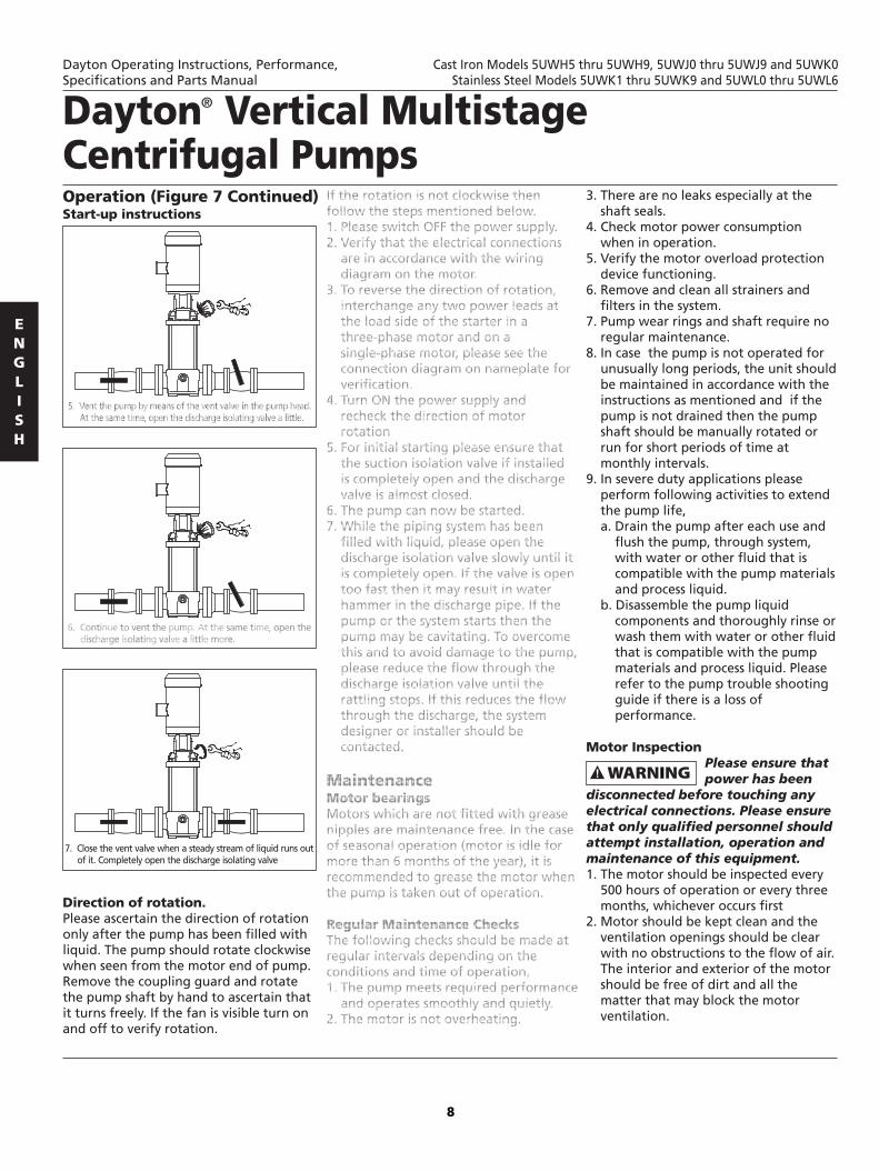
OperationStart-up instructions
Direction of rotation.Please ascertain the direction of rotation only after the pump has been filled with liquid. The pump should rotate clockwise when seen from the motor end of pump.Remove the coupling guard and rotate the pump shaft by hand to ascertain that it turns freely. If the fan is visible turn on and off to verify rotation.
(Figure 7 Continued)
7. Close the vent valve when a steady stream of liquid runs out of it. Completely open the discharge isolating valve
5. Vent the pump by means of the vent valve in the pump head. At the same time, open the discharge isolating valve a little.
6. Continue to vent the pump. At the same time, open the discharge isolating valve a little more.
If the rotation is not clockwise then follow the steps mentioned below.1. Please switch OFF the power supply.2. Verify that the electrical connections
are in accordance with the wiring diagram on the motor.
3. To reverse the direction of rotation, interchange any two power leads at the load side of the starter in a three-phase motor and on a single-phase motor, please see the connection diagram on nameplate for verification.
4. Turn ON the power supply and recheck the direction of motor rotation
5. For initial starting please ensure that the suction isolation valve if installed is completely open and the discharge valve is almost closed.
6. The pump can now be started.7. While the piping system has been
filled with liquid, please open the discharge isolation valve slowly until it is completely open. If the valve is open too fast then it may result in water hammer in the discharge pipe. If the pump or the system starts then the pump may be cavitating. To overcome this and to avoid damage to the pump, please reduce the flow through the discharge isolation valve until the rattling stops. If this reduces the flow through the discharge, the system designer or installer should be contacted.
MaintenanceMotor bearingsMotors which are not fitted with grease nipples are maintenance free. In the case of seasonal operation (motor is idle for more than 6 months of the year), it is recommended to grease the motor when the pump is taken out of operation.
Regular Maintenance ChecksThe following checks should be made at regular intervals depending on the conditions and time of operation, 1. The pump meets required performance
and operates smoothly and quietly.2. The motor is not overheating.
2. 2.
2. 2. 2. 2. 2. 2.
2. 2.
2. 2. 2.
2. 2. 2. 2. 2. 2. 2. 2. 2. 2. 2. 2. 2. 2.
2.
3. There are no leaks especially at the shaft seals.
4. Check motor power consumption when in operation.
5. Verify the motor overload protection device functioning.
6. Remove and clean all strainers and filters in the system.
7. Pump wear rings and shaft require no regular maintenance.
8. In case the pump is not operated for unusually long periods, the unit should be maintained in accordance with the instructions as mentioned and if the pump is not drained then the pump shaft should be manually rotated or run for short periods of time at monthly intervals.
9. In severe duty applications please perform following activities to extend the pump life,a. Drain the pump after each use and
flush the pump, through system, with water or other fluid that is compatible with the pump materials and process liquid.
b. Disassemble the pump liquid components and thoroughly rinse or wash them with water or other fluid that is compatible with the pump materials and process liquid. Please refer to the pump trouble shooting guide if there is a loss of performance.
Motor Inspection Please ensure that power has been disconnected before touching any electrical connections. Please ensure that only qualified personnel should attempt installation, operation and maintenance of this equipment.1. The motor should be inspected every
500 hours of operation or every three months, whichever occurs first
2. Motor should be kept clean and the ventilation openings should be clear with no obstructions to the flow of air. The interior and exterior of the motor should be free of dirt and all the matter that may block the motor ventilation.
2.
2.
2.
2.
2.
2. 2. 2. 2. 2. 2. 2.
2. 2. 2. 2. a. 2. a. 2. a. 2. a. 2. 2. a. 2. a. 2. a. 2. a. 2. a. 2. a. 2. a.
1. 1.
1. 1. 1. 1. 1. 1.
Dayton Operating Instructions, Performance,Specifications and Parts Manual
Cast Iron Models 5UWH5 thru 5UWH9, 5UWJ0 thru 5UWJ9 and 5UWK0Stainless Steel Models 5UWK1 thru 5UWK9 and 5UWL0 thru 5UWL6
Dayton Vertical Multistage Centrifugal Pumps

9
Maintenance (Continued)3. The insulation resistance of the motor
windings should be periodically measured and any significant drop should be immediately investigated.
Note: Reference figure 8 Repair Parts List on pages 11 - 16 during Motor replacement and Pump Replacement procedures
Motor Replacement1. Power supply to the equipment should
be disconnected2. Please close the suction and discharge
isolation valves3. Remove the coupling guards.4. Remove the screws and the coupling
(ref # 9) halves from the shaft.5. Remove the coupling pin (ref # 8).6. Remove the screws and washers that
hold the motor and the pump head (ref # 2) together.
7. Pull the old motor up from the pumphead and notice the location of the terminal box.
8. Clean the surfaces of the mounting flange.
9. Install the new motor on the pump.10. Reinstall the washers and screws that
hold motor and the pump head together.
11. Tighten the screws evenly.12. Reinstall the shaft pin in the shaft.13. Clean the coupling surfaces
thoroughly prior to assembly.14. Reinstall the coupling halves on the
pump and motor shaft and engage the shaft pin.
15. Close fit the screws until the coupling halves begin to bind.
16. Make sure the gap between the coupling halves is equal on both the sides. Please make sure that the shafts are axially alined.
17. Reinstall the coupling guards and make sure the guards are in place before the unit is turned on.
18. Kindly open the suction and discharge valves.
19. Turn the power back ON.
1. 1. 1.
1.
1.
1.
1. 1.
1. 1.
1.
1. 1.
1.
1. 1.
1.
1. 1. 1.
1. 1.
1.
Pump ReplacementPlease follow the steps 1 to 7 mentioned under motor replacement and then proceed further as mentioned below.
1. Remove the staybolts and washers.2. Lift the motor stool from the pump
head.3. Remove pump head and note the
position of the priming plug which would be needed to return to its original position during reassembly.
4. Remove and discard the upper O-ring/gasket.
5. Remove and replace the spring.6. Pull the old stack out of the sleeve by
pulling straight up, the pump shaft.7. Remove the sleeve.8. Remove and discard the bottom
O-ring/gasket.9. Clean the O-ring/gasket seat.10. Remove the suction and discharge
flange.11. Remove and discard the O-ring from
suction / discharge.12. Install a new lower O- ring/gasket.13. Install the new stack without
stainless steel sleeve and make sure to maintain correct alignment of the components.
14. Use a rubber mallet and tap the stainless steel sleeve into its position.
15. Install a new mechanical shaft seal.16. Install a new upper O- ring/gasket.17. Install a new round spring ring or
stack spring.18. Reinstall the motor stool on the
pump body. Align the priming plug to its original position.
19. Oil the threads on the staybolts.20. Replace the washers and staybolt
nuts and the staybolts.21. Reinstall the motor on the motor
stool and turn the motor to the desired terminal box position.
22. Follow steps starting from 10 under 'Motor Replacement' till the end.
1.
1. 1. 1.
1.
1.
1.
1.
1.
1. 1. 1.
1.
1.
1. 1.
1.
1. 1.
1.
Pumps which are not being used during periods of frost should be drained to avoid damage. Drain the pump by loosening the vent screw in the pump head and by removing the drain plug from the base Care must be taken to ensure that the escaping water does not cause injury to persons or damage to the motor or other components. In hot water installations, special attention should be paid to the risk of injury caused by scalding hot water. Do not tighten the vent screw and replace the drain plug until the pump is to be used again.
ServiceIf a pump has been used for a liquid which is injurious to health or toxic, the pump will be classified as contaminated. If Dayton is requested to service the pump, Dayton must be contacted with details about the pumped liquid, etc. before the pump is returned for service. Otherwise Dayton can refuse to accept the pump for service. Possible costs of returning the pump are paid by the customer. However, any application for service (no matter to whom it may be made) must include details about the pumped liquid if the pump has been used for liquids which are injurious to health or toxic.
Frost protection
Dayton Operating Instructions, Performance,Specifications and Parts Manual
Cast Iron Models 5UWH5 thru 5UWH9, 5UWJ0 thru 5UWJ9 and 5UWK0Stainless Steel Models 5UWK1 thru 5UWK9 and 5UWL0 thru 5UWL6

10
Troubleshooting ChartBefore removing the terminal box cover and before any removal/dismantling of the pump, make sure that the electric supply has been switched off and that it cannot be accidentally switched on.
Motor does not run
when started.
Motor starter overload
trips out immediately when
supply is switched on.
Motor starter overload
trips out occasionally.
Motor starter has not
tripped out but the
pump does not run.
Pump capacity not
constant.
Pumps run but gives
no water.
Pump runs backwards
when switched off.
Leakage in shaft seal.
Noise.
Symptom Possible Causes (s) Corrective Action
1. Supply failure.
2. Fuses are blown.
3. Motor starter overload has tripped out.
4. Thermal protection has tripped out.
5. Main contacts in motor starter are not
making contact or the coil is faulty.
6. Control circuit is defective.
7. Motor is defective.
1. Fuse or automatic circuit breaker is blown.
2. Contacts in motor starter overload are
faulty.
3. Cable connection is loose or faulty.
4. Motor winding is defective.
5. Pump mechanically blocked.
6. Overload setting is too low.
1. Low voltage at peak times.
2. Overload setting is too low.
Check 1, 2, 3, 4, and 5 in possible causes (s)
again motor dose not run when started
mentioned above.
1. Pump inlet pressure is too low (cavitation).
2. Suction pipe/pump partly blocked by
impurities.
3. Pump draws in air
1. Suction pipe/pump blocked by impurities.
2. Foot or non-return valve blocked in closed
position.
3. Leakage in suction pipe.
4. Air in suction pipe or pump.
5. Motor rotates in the wrong direction.
1. Leakage in suction pipe.
2. Foot or non-return valve is defective.
Shaft seal is defective.
1. Cavitation occurs in the pump.
2. Pump does not rotate freely (frictional
resistance) because of incorrect pump
shaft position
2.
2.
2.
2.
2.
2.
1. Connect the electricity supply.
2. Replace fuses.
3. Reactivate the motor protection
4. Reactivate the thermal protection.
5. Replace contacts or magnetic coil.
6. Repair the control circuit.
7. Replace the motor.
1. Replace fuse or automatic circuit breaker
2. Replace motor starter contacts.
3. Fasten or replace the cable connection.
4. Replace the motor.
5. Remove mechanical blocking of the pump.
6. Set the motor starter correctly.
1. Check the electricity supply.
2. Set the motor starter correctly.
1. Check the suction conditions.
2. Clean the pump or suction pipe.
3. Check the suction conditions.
1. Clean the pump or suction pipe.
2. Repair the foot or non-return valve.
3. Repair the suction pipe.
4. Check the suction conditions.
5. Change the direction of rotation of motor.
1. Repair the suction pipe.
2. Repair the foot or non-return valve.
Replace the shaft seal.
1. Check the suction conditions.
2. Adjust the pump shaft.
Dayton Operating Instructions, Performance,Specifications and Parts Manual
Cast Iron Models 5UWH5 thru 5UWH9, 5UWJ0 thru 5UWJ9 and 5UWK0Stainless Steel Models 5UWK1 thru 5UWK9 and 5UWL0 thru 5UWL6
Dayton Vertical Multistage Centrifugal Pumps
11
Dayton Operating Instructions, Performance,Specifications and Parts Manual
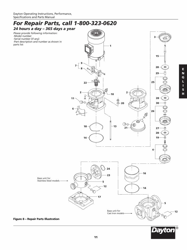
24 hours a day – 365 days a yearPlease provide following information:-Model number-Serial number (if any)-Part description and number as shown in parts list
For Repair Parts, call 1-800-323-0620
Figure 8 – Repair Parts Illustration
13 21
14
18
24
23
5
17
16
14
5
6
11
2
22
8
9
10
20
2
15
28
29
25
28
30
26
27
28
19
4
3
7
1
12
12
Base unit for Stainless Steel models
Base unit for Cast Iron models

12
Dayton Operating Instructions, Performance,Specifications and Parts Manual
Cast Iron Models 5UWH5 thru 5UWH9, 5UWJ0 thru 5UWJ9 and 5UWK0Stainless Steel Models 5UWK1 thru 5UWK9 and 5UWL0 thru 5UWL6
Repair Parts List (Cast Iron Models)
1
111121121114211-114-1--136814121223589111713681412
PPLTFB21TBG/PPLTFB23TCGPP6001GPP6002GPP6003GPP6004GPP6005GPP6008GPP6010GPP6011GPP6012GPP6013GPP6014GPP6015GPP6018GPP6019GPP6020G-PP6021GPP6022GPP6023G-PP6026G-------PP6054AG-PP6057AG-PP6058AG-----------PP6060AG-
Part Number For Models :
DescriptionRef. No. Qty.
5UWH9/5UWJ0
5UWJ1/5UWJ7
5UWJ2/5UWJ8
5UWJ3/5UWJ9
5UWJ4/5UWK0
5UWH5/5UWH6
PPLTFC21TBG/PPLTFC23TCGPP6001GPP6002GPP6003GPP6004GPP6005GPP6008GPP6010GPP6011GPP6012GPP6013GPP6014GPP6027GPP6018GPP6032GPP6037G-PP6021GPP6022GPP6023G-PP6026G--PP6053AG----PP6054AG-PP6057AG--PP6058BG-----PP6059AG----PP6060AG-
PPLTFD21TBG/PPLTFD23TCGPP6001GPP6002GPP6003GPP6004GPP6005GPP6008GPP6010GPP6011GPP6012GPP6013GPP6014GPP6028GPP6018GPP6033GPP6038G-PP6021GPP6022GPP6023G-PP6026G---PP6053BG---PP6054AG-PP6057AG---PP6058CG-----PP6059BG---PP6060AG-
PPLTFE21TBG/PPLTFE23TCGPP6001GPP6002GPP6003GPP6004GPP6005GPP6008GPP6010GPP6011GPP6012GPP6013GPP6014GPP6029GPP6018GPP6034GPP6039G-PP6021GPP6022GPP6023G-PP6026G----PP6053CG--PP6054AG-PP6057AG----PP6058DG-----PP6059CG--PP6060AG-
PPLTFF21TBG/PPLTFF23TCGPP6001GPP6002GPP6003GPP6004GPP6005GPP6008GPP6010GPP6011GPP6012GPP6013GPP6014GPP6030GPP6018GPP6035GPP6040G-PP6021GPP6022GPP6023G-PP6026G-----PP6053DG--PP6054BG-PP6057BG-----PP6058EG----PP6059DG--PP6060BG
PPLTFG21TEG/PPLTFG23TCGPP6001GPP6002GPP6003GPP6004GPP6005GPP6008GPP6010GPP6011GPP6012GPP6013GPP6014GPP6031GPP6018GPP6036GPP6041G-PP6021GPP6022GPP6023G-PP6026G------PP6053EG-PP6054BG-PP6057BG------PP6058FG----PP6059EG-PP6060BG
1.
2.3.4.5.6.7.8.9.10.11.12.13.14.15.16.17.18.19.20.21.22.23.24.25.
26.
27.
28.
29.
30.
Motor
Pump HeadBowl TopBottom Bowl † BaseCoupling GuardCoupling CompleteCoupling PinCouplingAir vent completeWater plugDrain Plug with O-ringStay BoltO – ring Pump ShaftOuter SleeveBaseplateSpringSleeve for lock nutWasherPump Head CoverMechanical SealFlangeLock ringStage Bowl †*Stage Bowl †*Stage Bowl †*Stage Bowl †*Stage Bowl †*Bearing Bowl ‡*Bearing Bowl ‡*Bearing Ring Sleeve*Bearing Ring Sleeve*Impeller*Impeller*Impeller*Impeller*Impeller*Impeller*Impeller*Stage Spacing Pipe*Stage Spacing Pipe*Stage Spacing Pipe*Stage Spacing Pipe*Stage Spacing Pipe*Bearing Spacing Pipe*Bearing Spacing Pipe*
NOTE : * Please refer above table for ordering parts and required quantities. - Not applicable. † with Neckring and Neckring Retainer. ‡ with Neckring, Neckring Retainer and Bearing

13
Dayton Operating Instructions, Performance,Specifications and Parts Manual
Cast Iron Models 5UWH5 thru 5UWH9, 5UWJ0 thru 5UWJ9 and 5UWK0Stainless Steel Models 5UWK1 thru 5UWK9 and 5UWL0 thru 5UWL6
Repair Parts List (Cast Iron Models)
1
111121121114211-114-1--136814121223589111713681412
Part Number For Models :
DescriptionRef. No. Qty.
1.
2.3.4.5.6.7.8.9.10.11.12.13.14.15.16.17.18.19.20.21.22.23.24.25.
26.
27.
28.
29.
30.
Motor
Pump HeadBowl TopBottom Bowl † BaseCoupling GuardCoupling CompleteCoupling PinCouplingAir vent completeWater plugDrain Plug with O-ringStay BoltO – ring Pump ShaftOuter SleeveBaseplateSpringSleeve for lock nutWasherPump Head CoverMechanical SealFlangeLock ringStage Bowl †*Stage Bowl †*Stage Bowl †*Stage Bowl †*Stage Bowl †*Bearing Bowl ‡*Bearing Bowl ‡*Bearing Ring Sleeve*Bearing Ring Sleeve*Impeller*Impeller*Impeller*Impeller*Impeller*Impeller*Impeller*Stage Spacing Pipe*Stage Spacing Pipe*Stage Spacing Pipe*Stage Spacing Pipe*Stage Spacing Pipe*Bearing Spacing Pipe*Bearing Spacing Pipe*
5UWH7/5UWH8 5UWJ5 5UWJ6
PPLTFC21TBG/PPLTFC23TCGPP6001GPP6042GPP6043GPP6004GPP6005GPP6008GPP6010GPP6011GPP6012GPP6013GPP6014GPP6044GPP6018GPP6045GPP6046G-PP6021GPP6022GPP6023G-PP6026G-------PP6078AG-PP6057AG-PP6080AG-----------PP6082AG-
PPLTFF21TBG
PP6001GPP6042GPP6043GPP6004GPP6005GPP6008GPP6010GPP6011GPP6012GPP6013GPP6014GPP6047GPP6018GPP6048GPP6049G-PP6021GPP6022GPP6023G-PP6026G---PP6077AG---PP6078AG-PP6057AG---PP6080BG-----PP6081AG---PP6082AG-
PPLTFG21TEG
PP6001GPP6042GPP6043GPP6004GPP6005GPP6008GPP6010GPP6011GPP6012GPP6013GPP6014GPP6050GPP6018GPP6051GPP6052G-PP6021GPP6022GPP6023G-PP6026G----PP6077BG---PP6078BG-PP6057BG----PP6080CG----PP6081BG---PP6082BG
NOTE : * Please refer above table for ordering parts and required quantities. - Not applicable. † with Neckring and Neckring Retainer. ‡ with Neckring, Neckring Retainer and Bearing

14
Dayton Operating Instructions, Performance,Specifications and Parts Manual
Cast Iron Models 5UWH5 thru 5UWH9, 5UWJ0 thru 5UWJ9 and 5UWK0Stainless Steel Models 5UWK1 thru 5UWK9 and 5UWL0 thru 5UWL6
Repair Parts List (Stainless Steel Models)
Motor
Pump HeadBowl TopBottom Bowl † BaseCoupling GuardCoupling CompleteCoupling PinCouplingAir vent completeWater plugDrain Plug with O-ringStay BoltO – ring Pump ShaftOuter SleeveBaseplateSpringSleeve for lock nutWasherPump Head CoverMechanical SealFlangeLock ringStage Bowl †*Stage Bowl †*Stage Bowl †*Stage Bowl †*Stage Bowl †*Bearing Bowl ‡*Bearing Bowl ‡*Bearing Ring Sleeve*Bearing Ring Sleeve*Impeller*Impeller*Impeller*Impeller*Impeller*Impeller*Impeller*Stage Spacing Pipe*Stage Spacing Pipe*Stage Spacing Pipe*Stage Spacing Pipe*Stage Spacing Pipe*Bearing Spacing Pipe*Bearing Spacing Pipe*
1.
2.3.4.5.6.7.8.9.10.11.12.13.14.15.16.17.18.19.20.21.22.23.24.25.
26.
27.
28.
29.
30.
1
11112112111421111141122136814121223589111713681412
PPLTFB21TBG/PPLTFB23TCGPP6062GPP6002GPP6003GPP6063GPP6005GPP6008GPP6010GPP6011GPP6012GPP6013GPP6014GPP6064GPP6018GPP6019GPP6020GPP6065GPP6021GPP6022GPP6023GPP6066GPP6026GPP6067GPP6068G-----PP6054AG-PP6057AG-PP6058AG-----------PP6060AG-
Part Number For Models :
DescriptionRef. No. Qty.
5UWK5/5UWK6
5UWK7/5UWL3
5UWK8/5UWL4
5UWK9/5UWL5
5UWL0/5UWL6
5UWK1/5UWK2
PPLTFC21TBG/PPLTFC23TCGPP6062GPP6002GPP6003GPP6063GPP6005GPP6008GPP6010GPP6011GPP6012GPP6013GPP6014GPP6069GPP6018GPP6032GPP6037GPP6065GPP6021GPP6022GPP6023GPP6066GPP6026GPP6067GPP6068GPP6053AG----PP6054AG-PP6057AG--PP6058BG-----PP6059AG----PP6060AG-
PPLTFD21TBG/PPLTFD23TCGPP6062GPP6002GPP6003GPP6063GPP6005GPP6008GPP6010GPP6011GPP6012GPP6013GPP6014GPP6070GPP6018GPP6033GPP6038GPP6065GPP6021GPP6022GPP6023GPP6066GPP6026GPP6067GPP6068G-PP6053BG---PP6054AG-PP6057AG---PP6058CG-----PP6059BG---PP6060AG-
PPLTFE21TBG/PPLTFE23TCGPP6062GPP6002GPP6003GPP6063GPP6005GPP6008GPP6010GPP6011GPP6012GPP6013GPP6014GPP6071GPP6018GPP6034GPP6039GPP6065GPP6021GPP6022GPP6023GPP6066GPP6026GPP6067GPP6068G--PP6053CG--PP6054AG-PP6057AG----PP6058DG-----PP6059CG--PP6060AG-
PPLTFF21TBG/PPLTFF23TCGPP6062GPP6002GPP6003GPP6063GPP6005GPP6008GPP6010GPP6011GPP6012GPP6013GPP6014GPP6072GPP6018GPP6035GPP6040GPP6065GPP6021GPP6022GPP6023GPP6066GPP6026GPP6067GPP6068G---PP6053DG--PP6054BG-PP6057BG-----PP6058EG----PP6059DG--PP6060BG
PPLTFG21TEG/PPLTFG23TCGPP6062GPP6002GPP6003GPP6063GPP6005GPP6008GPP6010GPP6011GPP6012GPP6013GPP6014GPP6073GPP6018GPP6036GPP6041GPP6065GPP6021GPP6022GPP6023GPP6066GPP6026GPP6067GPP6068G----PP6053EG-PP6054BG-PP6057BG------PP6058FG----PP6059EG-PP6060BG
NOTE : * Please refer above table for ordering parts and required quantities. - Not applicable. † with Neckring and Neckring Retainer. ‡ with Neckring, Neckring Retainer and Bearing

15
Dayton Operating Instructions, Performance,Specifications and Parts Manual
Cast Iron Models 5UWH5 thru 5UWH9, 5UWJ0 thru 5UWJ9 and 5UWK0Stainless Steel Models 5UWK1 thru 5UWK9 and 5UWL0 thru 5UWL6
Repair Parts List (Stainless Steel Models)
Motor
Pump HeadBowl TopBottom Bowl † BaseCoupling GuardCoupling CompleteCoupling PinCouplingAir vent completeWater plugDrain Plug with O-ringStay BoltO – ring Pump ShaftOuter SleeveBaseplateSpringSleeve for lock nutWasherPump Head CoverMechanical SealFlangeLock ringStage Bowl †*Stage Bowl †*Stage Bowl †*Stage Bowl †*Stage Bowl †*Bearing Bowl ‡*Bearing Bowl ‡*Bearing Ring Sleeve*Bearing Ring Sleeve*Impeller*Impeller*Impeller*Impeller*Impeller*Impeller*Impeller*Stage Spacing Pipe*Stage Spacing Pipe*Stage Spacing Pipe*Stage Spacing Pipe*Stage Spacing Pipe*Bearing Spacing Pipe*Bearing Spacing Pipe*
1.
2.3.4.5.6.7.8.9.10.11.12.13.14.15.16.17.18.19.20.21.22.23.24.25.
26.
27.
28.
29.
30.
1
11112112111421111141122136814121223589111713681412
Part Number For Models :
DescriptionRef. No. Qty.
5UWK3/5UWK4 5UWL1 5UWL2
PPLTFC21TBG/PPLTFC23TCGPP6062GPP6042GPP6043GPP6063GPP6005GPP6008GPP6010GPP6011GPP6012GPP6013GPP6014GPP6074GPP6018GPP6045GPP6046GPP6065GPP6021GPP6022GPP6023GPP6066GPP6026GPP6067GPP6068G-----PP6078AG-PP6057AG-PP6080AG-----------PP6082AG-
PPLTFF21TBG
PP6062GPP6042GPP6043GPP6063GPP6005GPP6008GPP6010GPP6011GPP6012GPP6013GPP6014GPP6075GPP6018GPP6048GPP6049GPP6065GPP6021GPP6022GPP6023GPP6066GPP6026GPP6067GPP6068G-PP6077AG---PP6078AG-PP6057AG---PP6080BG-----PP6081AG---PP6082AG-
PPLTFG21TEG
PP6062GPP6042GPP6043GPP6063GPP6005GPP6008GPP6010GPP6011GPP6012GPP6013GPP6014GPP6076GPP6018GPP6051GPP6052GPP6065GPP6021GPP6022GPP6023GPP6066GPP6026GPP6067GPP6068G--PP6077BG---PP6078BG-PP6057BG----PP6080CG----PP6081BG---PP6082BG
NOTE : * Please refer above table for ordering parts and required quantities. - Not applicable. † with Neckring and Neckring Retainer. ‡ with Neckring, Neckring Retainer and Bearing

Dayton Operating Instructions, Performance,Specifications and Parts Manual
Cast Iron Models 5UWH5 thru 5UWH9, 5UWJ0 thru 5UWJ9 and 5UWK0Stainless Steel Models 5UWK1 thru 5UWK9 and 5UWL0 thru 5UWL6
16
Notes

Dayton Operating Instructions, Performance,Specifications and Parts Manual
Cast Iron Models 5UWH5 thru 5UWH9, 5UWJ0 thru 5UWJ9 and 5UWK0Stainless Steel Models 5UWK1 thru 5UWK9 and 5UWL0 thru 5UWL6
17
Notes

Manufactured for Dayton Electric Mfg. Co. Niles, Illinois 60714 U.S.A.
LIMITED WARRANTY
®DAYTON ONE-YEAR LIMITED WARRANTY. DAYTON VERTICAL MULTISTAGE CENTRIFUGAL PUMP, MODELS COVERED IN THIS MANUAL, ARE WARRANTED BY DAYTON ELECTRIC MFG. CO. (DAYTON) TO THE ORIGINAL USER AGAINST DEFECTS IN WORKMANSHIP OR MATERIALS UNDER NORMAL USE FOR ONE YEAR AFTER DATE OF PURCHASE. ANY PART WHICH IS DETERMINED TO BE DEFECTIVE IN MATERIAL OR WORKMANSHIP AND RETURNED TO AN AUTHORIZED SERVICE LOCATION, AS DAYTON DESIGNATES, SHIPPING COSTS PREPAID, WILL BE, AS THE EXCLUSIVE REMEDY, REPAIRED OR REPLACED AT DAYTON’S OPTION. FOR LIMITED WARRANTY CLAIM PROCEDURES, SEE “PROMPT DISPOSITION” BELOW. THIS LIMITED WARRANTY GIVES PURCHASERS SPECIFIC LEGAL RIGHTS WHICH VARY FROM JURISDICTION TO JURISDICTION.
LIMITATION OF LIABILITY. TO THE EXTENT ALLOWABLE UNDER APPLICABLE LAW, DAYTON’S LIABILITY FOR CONSEQUENTIALAND INCIDENTAL DAMAGES IS EXPRESSLY DISCLAIMED. DAYTON’S LIABILITY IN ALL EVENTS IS LIMITED TO AND SHALL NOTEXCEED THE PURCHASE PRICE PAID.
WARRANTY DISCLAIMER. A DILIGENT EFFORT HAS BEEN MADE TO PROVIDE PRODUCT INFORMATION AND ILLUSTRATETHE PRODUCTS IN THIS LITERATURE ACCURATELY; HOWEVER, SUCH INFORMATION AND ILLUSTRATIONS ARE FOR THE SOLEPURPOSE OF IDENTIFICATION, AND DO NOT EXPRESS OR IMPLY A WARRANTY THAT THE PRODUCTS ARE MERCHANTABLE,OR FIT FOR A PARTICULAR PURPOSE, OR THAT THE PRODUCTS WILL NECESSARILY CONFORM TO THE ILLUSTRATIONS ORDESCRIPTIONS. EXCEPT AS PROVIDED BELOW, NO WARRANTY OR AFFIRMATION OF FACT, EXPRESSED OR IMPLIED, OTHERTHAN AS STATED IN THE “LIMITED WARRANTY” ABOVE IS MADE OR AUTHORIZED BY DAYTON.
Technical Advice and Recommendations, Disclaimer. Notwithstanding any past practice or dealings or trade custom,sales shall not include the furnishing of technical advice or assistance or system design. Dayton assumes no obligations orliability on account of any unauthorized recommendations, opinions or advice as to the choice, installation or use ofproducts.
Product Suitability. Many jurisdictions have codes and regulations governing sales, construction, installation, and/or use ofproducts for certain purposes, which may vary from those in neighboring areas. While attempts are made to assure thatDayton products comply with such codes, Dayton cannot guarantee compliance, and cannot be responsible for how theproduct is installed or used. Before purchase and use of a product, review the product applications, and all applicablenational and local codes and regulations, and be sure that the product, installation, and use will comply with them.
Certain aspects of disclaimers are not applicable to consumer products; e.g., (a) some jurisdictions do not allow the exclusionor limitation of incidental or consequential damages, so the above limitation or exclusion may not apply to you; (b) also,some jurisdictions do not allow a limitation on how long an implied warranty lasts, consequently the above limitation maynot apply to you; and (c) by law, during the period of this Limited Warranty, any implied warranties of impliedmerchantability or fitness for a particular purpose applicable to consumer products purchased by consumers, may not beexcluded or otherwise disclaimed.
Prompt Disposition. A good faith effort will be made for prompt correction or other adjustment with respect to anyproduct which proves to be defective within limited warranty. For any product believed to be defective within limitedwarranty, first write or call dealer from whom the product was purchased. Dealer will give additional directions. If unable toresolve satisfactorily, write to Dayton at address below, giving dealer’s name, address, date, and number of dealer’s invoice,and describing the nature of the defect. Title and risk of loss pass to buyer on delivery to common carrier. If product wasdamaged in transit to you, file claim with carrier.
Manufactured for Dayton Electric Mfg. Co. 5959 W. Howard St., Niles, Illinois 60714-4014 U.S.A.
Dayton Operating Instructions, Performance,Specifications and Parts Manual
Cast Iron Models 5UWH5 thru 5UWH9, 5UWJ0 thru 5UWJ9 and 5UWK0Stainless Steel Models 5UWK1 thru 5UWK9 and 5UWL0 thru 5UWL6
Dayton Vertical Multistage Centrifugal Pumps